

Page 1

HP E5000 Messaging System for Microsoft Exchange Administrator Guide
Abstract
This document explains how to install, configure, and maintain all models of the HP E5000 Series Messaging System for
Microsoft Exchange. The intended audience is decision makers, IT support staff, and project managers involved in planning
and deploying Microsoft Exchange Server 2010 solutions. For more information on Exchange 2010 terminology and best
practices, go to http://www.hp.com/solutions/activeanswers/exchange. For the latest version of this guide, go to www.hp.com/
support/manuals. Select Solution appliances in the solutions group, and then select an E5000 product.
HP Part Number: 5697-1789
Published: June 2012
Edition: 3
Page 2

© Copyright 2011, 2012 Hewlett-Packard Development Company, L.P.
Confidential computer software. Valid license from HP required for possession, use or copying. Consistent with FAR 12.211 and 12.212, Commercial
Computer Software, Computer Software Documentation, and Technical Data for Commercial Items are licensed to the U.S. Government under
vendor's standard commercial license.
The information contained herein is subject to change without notice. The only warranties for HP products and services are set forth in the express
warranty statements accompanying such products and services. Nothing herein should be construed as constituting an additional warranty. HP shall
not be liable for technical or editorial errors or omissions contained herein.
Acknowledgments
Microsoft®, Windows®, and Windows Server® are registered trademarks of Microsoft Corporation in the United States and other countries.
Revision History
DateEdition
DescriptionSoftware
Version
First release1.0February 2011First
2.01September 2011Second
Documented E5000 Configuration Wizard, Exchange Deployment Tool, E5000
System Manager, and System Management Homepage improvements. Added
appendices for E5000 error codes and troubleshooting. Updated details for
using the EMU CLI and physical interface. Updated information about network
connections.
2.03August 2012Third
Documented new Recovery LUN Manager and Storage Viewer features.
Documented E5000 Configuration Wizard, Exchange Deployment Tool, and
Alerts and Email improvements. Added requirement for installing Exchange
2010 SP2. Updated information about network connections. Updated details
for using the EMU CLI and physical interface.
Page 3

Contents
1 HP E5000 Messaging Systems for Microsoft Exchange....................................7
Features..................................................................................................................................7
Hardware components..............................................................................................................7
Software components................................................................................................................8
2 Preparing to install the messaging system.....................................................10
Exchange Server 2010 network requirements..............................................................................10
Network connections..............................................................................................................10
3 Installing the messaging system..................................................................14
Verify the kit contents..............................................................................................................14
Locate and record the product number, serial number, and SAID number.......................................14
Unpack and rack the messaging system hardware......................................................................14
Cable expansion disk enclosures..............................................................................................16
Power on the messaging system................................................................................................17
Configure the EMU and iLO management processors..................................................................17
Accessing the messaging system...............................................................................................20
Adding expansion disk enclosures to an installed messaging system..............................................21
Adding hard drives to an installed E5000 system........................................................................21
4 Configuring the messaging system software.................................................23
Configuring server software.....................................................................................................23
Deploying Microsoft Exchange Server 2010...............................................................................26
Using Microsoft Exchange Jetstress and Load Generator (optional)................................................32
5 Monitoring and troubleshooting the messaging system..................................34
Using notification alerts...........................................................................................................34
Configuring Alerts and Email...................................................................................................34
HP System Management Homepage.........................................................................................38
Starting the System Management Homepage application........................................................38
System Management Homepage main page.........................................................................38
Using the System Manager......................................................................................................42
Component LEDs....................................................................................................................47
EMU CLI SHOW commands....................................................................................................55
Using Recovery LUN Manager.................................................................................................55
Using Storage Viewer..............................................................................................................56
HP Support websites...............................................................................................................58
HP Insight Remote Support software..........................................................................................58
Microsoft Systems Center Operations Manager...........................................................................59
HP 1210m Volume Online Tool.................................................................................................59
Obtaining the Service Agreement ID.........................................................................................60
Locating the messaging system warranty entitlement label............................................................60
6 Upgrading the messaging system...............................................................61
Determining the current messaging system software version..........................................................61
Upgrading E5000 software.....................................................................................................61
Upgrading a component's firmware..........................................................................................62
Resolving errors after the HP 1210m controller upgrade...........................................................66
Resolving an EMU upgrade issue..............................................................................................67
Upgrading hardware components.............................................................................................67
Powering the system off and on................................................................................................67
7 Removing and replacing hardware components............................................69
Customer self repair................................................................................................................69
Contents 3
Page 4

Best practices for replacing components....................................................................................69
During replacement of the failed component..........................................................................69
Accessing component replacement videos.............................................................................69
Identifying the spare part....................................................................................................70
Replaceable parts...................................................................................................................70
Hot, warm, and cold swap components.....................................................................................73
Preventing electrostatic discharge..............................................................................................73
Verifying component failure......................................................................................................73
Verifying proper operation.......................................................................................................74
Wait times for hard disks.........................................................................................................74
Removing the system enclosure from the rack..............................................................................75
Inserting the system enclosure into the rack.................................................................................76
Removing and replacing the server interposer board...................................................................76
Removing and replacing the midplane board.............................................................................78
Removing and replacing a SAS cable .......................................................................................81
Removing and replacing the SAS I/O module............................................................................81
Removing and replacing the fan module....................................................................................83
Removing and replacing the power UID button assembly.............................................................84
Removing and replacing the power supply.................................................................................85
Removing and replacing the HP Ethernet I/O module..................................................................86
Removing and replacing the PCIe module (with card)..................................................................87
Removing and replacing the EMU module.................................................................................89
Removing and replacing the server blade backplane...................................................................90
Removing and replacing the server airflow baffle........................................................................92
Removing and replacing the front bezel (standard)......................................................................93
Removing and replacing the front bezel (full)..............................................................................95
Removing and replacing the front LED display board in the rack (standard)....................................96
Removing and replacing the front LED display board (full)............................................................97
Removing and replacing a drive drawer....................................................................................99
Removing and replacing the drive drawer hard drive.................................................................104
Removing and replacing the drive drawer rails (side or bottom)..................................................106
Removing and replacing the enclosure rails..............................................................................111
Removing and replacing the rack rails.....................................................................................116
Removing and replacing server blades....................................................................................116
Removing and replacing the server blade hard drive.................................................................117
Removing and replacing the 1210m controller board components...............................................119
Removing and replacing the 1210m cache module...............................................................121
Removing and replacing the capacitor pack........................................................................124
Removing and replacing the Mezzanine NIC...........................................................................126
8 Messaging system recovery......................................................................128
System Recovery DVD...........................................................................................................128
Restoring the factory image with a DVD or USB flash device.......................................................128
Using a USB flash drive for messaging system recovery..............................................................128
Managing disks after a system restoration................................................................................129
Restoration in nonproduction environments..........................................................................130
Restoration in production environments................................................................................130
9 Support and other resources....................................................................131
Contacting HP......................................................................................................................131
HP technical support........................................................................................................131
Subscription service..........................................................................................................131
Related information...............................................................................................................131
HP websites....................................................................................................................131
Microsoft websites............................................................................................................132
Rack stability........................................................................................................................132
4 Contents
Page 5

10 Documentation feedback.......................................................................133
A Managing the EMU................................................................................134
CLI reference........................................................................................................................134
Command line conventions....................................................................................................134
Operational groups..............................................................................................................134
Authentication......................................................................................................................135
Time functions......................................................................................................................138
Inventory and status..............................................................................................................141
Internet control.....................................................................................................................147
Server management..............................................................................................................149
Enclosure control..................................................................................................................152
Forensic...............................................................................................................................156
Session...............................................................................................................................158
Using the Enclosure Manager physical interface.......................................................................161
Activate Button Menu............................................................................................................161
Reboot EM (bE)....................................................................................................................161
Restore Factory Defaults (Fd)..................................................................................................162
Recover Lost Password (Fp).....................................................................................................162
Set DHCP IP Address (dH).....................................................................................................162
Set Link Local IP Address (LL)..................................................................................................162
Display Current IP Address (IP)...............................................................................................163
Exit Button Menu..................................................................................................................163
B E5000 Error Codes................................................................................164
E5000 Configuration Wizard.................................................................................................164
System Manager..................................................................................................................166
E5000 Exchange Deployment Tool.........................................................................................167
Firmware Update..................................................................................................................168
Enclosure Manager Settings...................................................................................................170
Storage Viewer....................................................................................................................170
Recovery LUN Manager........................................................................................................171
CSP WBEM Providers............................................................................................................171
CMP...................................................................................................................................172
C Troubleshooting.....................................................................................176
E5000 Configuration Wizard.................................................................................................176
Exchange Deployment Tool....................................................................................................177
Microsoft Exchange..............................................................................................................178
Performance.........................................................................................................................179
D Regulatory compliance notices.................................................................180
Regulatory compliance identification numbers..........................................................................180
Federal Communications Commission notice............................................................................180
FCC rating label..............................................................................................................180
Class A equipment......................................................................................................180
Class B equipment......................................................................................................180
Modification...................................................................................................................181
Cables...........................................................................................................................181
Canadian notice (Avis Canadien)...........................................................................................181
Class A equipment...........................................................................................................181
Class B equipment...........................................................................................................181
European Union notice..........................................................................................................181
Japanese notices..................................................................................................................182
Japanese VCCI-A notice....................................................................................................182
Japanese VCCI-B notice....................................................................................................182
Japanese VCCI marking...................................................................................................182
Contents 5
Page 6

Japanese power cord statement.........................................................................................182
Korean notices.....................................................................................................................182
Class A equipment...........................................................................................................182
Class B equipment...........................................................................................................182
Taiwanese notices.................................................................................................................183
BSMI Class A notice.........................................................................................................183
Taiwan battery recycle statement........................................................................................183
Vietnamese notice............................................................................................................183
Laser compliance notices.......................................................................................................184
English laser notice..........................................................................................................184
Dutch laser notice............................................................................................................184
French laser notice...........................................................................................................184
German laser notice.........................................................................................................185
Italian laser notice............................................................................................................185
Japanese laser notice.......................................................................................................185
Spanish laser notice.........................................................................................................186
Recycling notices..................................................................................................................186
English recycling notice....................................................................................................186
Bulgarian recycling notice.................................................................................................187
Czech recycling notice......................................................................................................187
Danish recycling notice.....................................................................................................187
Dutch recycling notice.......................................................................................................187
Estonian recycling notice...................................................................................................188
Finnish recycling notice.....................................................................................................188
French recycling notice.....................................................................................................188
German recycling notice...................................................................................................188
Greek recycling notice......................................................................................................189
Hungarian recycling notice...............................................................................................189
Italian recycling notice......................................................................................................189
Latvian recycling notice.....................................................................................................189
Lithuanian recycling notice................................................................................................190
Polish recycling notice.......................................................................................................190
Portuguese recycling notice...............................................................................................190
Romanian recycling notice................................................................................................190
Slovak recycling notice.....................................................................................................191
Spanish recycling notice...................................................................................................191
Swedish recycling notice...................................................................................................191
Turkish recycling notice.....................................................................................................191
Battery replacement notices...................................................................................................192
Dutch battery notice.........................................................................................................192
French battery notice........................................................................................................192
German battery notice......................................................................................................193
Italian battery notice........................................................................................................193
Japanese battery notice....................................................................................................194
Spanish battery notice......................................................................................................194
Glossary..................................................................................................195
Index.......................................................................................................196
6 Contents
Page 7

1 HP E5000 Messaging Systems for Microsoft Exchange
The HP E5000 Messaging System for Microsoft Exchange (“messaging system”) is an integrated
hardware-software solution that simplifies the initial deployment of Microsoft Exchange Server
2010. Each messaging system features HP server blades and dense disk storage in a single 3U
enclosure (Figure 1 (page 8)). E5000 expansion disk enclosures are optional or standard
depending on the model. The following models are available:
• HP E5300 G2 Messaging System for Microsoft Exchange
• HP E5500 G2 Messaging System for Microsoft Exchange
• HP E5700 G2 Messaging System for Microsoft Exchange
Features
The HP E5000 Messaging System provides the following advantages:
• Each system ships from the factory with preintegrated hardware and preloaded software, to
significantly reduce the time and complexity of deploying Exchange 2010.
• Built on the HP converged application platform, which combines two server blades and dense
storage drawer into a single enclosure
• Simplified deployment with presized, tested, and optimized configurations
• Lower overall TCO with reduced footprint and lower energy consumption
• Presized configurations deliver high availability in hours instead of days
• Specially developed setup tools (setup wizards) provide guided setup assistance, performing
many of the complex and time-consuming tasks needed to configure and deploy a high
availability messaging system. The setup tools make it easy to get both Windows and Exchange
configured and running quickly.
• Automatic database-level recovery from failures
• HP and Microsoft management integration, including Microsoft Server Manager and System
Center and HP Systems Insight Manager and Integrated Lights Out (iLO)
For more information about E5000 Messaging System features, go to:
http://www.hp.com/go/E5000
Hardware components
Figure 1 (page 8) and Figure 2 (page 8) show front and rear views of the messaging system.
Features 7
Page 8
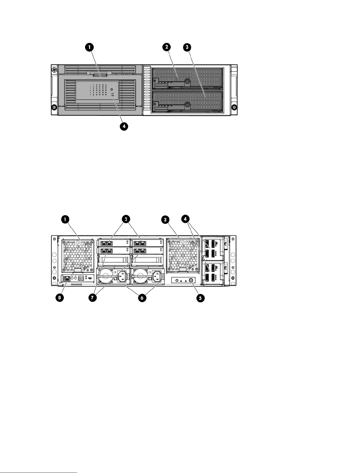
Figure 1 Front view
1. Disk drive drawer
2. Server blade 1, Bay 1
3. Server blade 2, Bay 2
4. Chassis fault LED
Figure 2 Rear view
1. System fan
2. HP 2-port Ethernet I/O module (2) (These modules connect to the NIC located on the server blade motherboard)
3. Drive fan
4. SAS I/O module (2)
5. Power button
6. Power supply (2)
7. HP 2-port Ethernet I/O module. These modules (2) connect to the NIC located on top of the Mezzanine card on the
server blade. Standard on the E5500 and E5700 and can be added as option for the E5300.
8. Management port (for iLO and Enclosure Manager Unit)
Software components
The E5000 Messaging System includes factory integration of the hardware and preloading of the
E5000 software image, including Windows Server 2008 R2, which has been preinstalled and
activated. The E5000 system configuration also includes the HP E5000 Messaging System
8 HP E5000 Messaging Systems for Microsoft Exchange
Page 9

Configuration Wizard and HP E5000 Messaging System Exchange Deployment Tool, which are
used to deploy the Exchange servers and storage in their optimal configurations.
The E5000 Configuration Wizard assists during the initial out of box setup and configuration of
the messaging system. This tool helps to configure each of the customer-specific settings needed
to prepare the server.
Exchange 2010 is then installed and configured using the E5000 Exchange Deployment Tool,
which has been developed to automate many of the deployment tasks.
To provide ongoing monitoring and facilitate management, the messaging system includes the
System Manager, which provides a snapshot view of the health and status of the messaging system
and tools to manage firmware updates.
Software components 9
Page 10

2 Preparing to install the messaging system
Before you install the messaging system, plan how you will integrate the system into your network
and whether you will use Insight Remote Support (see “HP Insight Remote Support software”
(page 58)). See the HP E5000 Messaging System for Microsoft Exchange Installation Checklist for
general planning information:
http://h20564.www2.hp.com/portal/site/hpsc/public/kb/docDisplay/?
docId=emr_na-c03168643
Exchange Server 2010 network requirements
Exchange Server 2010 includes a high-availability feature called DAG, which requires two networks:
• Client/MAPI network provides the following functions:
Server-to-server connectivity between the CAS, Hub Transport, and Mailbox server roles◦
◦ Server-to-server communication with domain controllers, global catalog servers, and name
services like DNS.
◦ Management of Exchange client traffic such as Outlook and Outlook Web Access
◦ Exchange client access to mail on CASs.
◦ Replication, if the replication network is unavailable.
• Replication network provides the cluster heartbeat, Exchange Server 2010 log shipping, and
database seeding or reseeding when available.
IMPORTANT: The Replication and MAPI networks should be isolated from each other, preventing
Client/MAPI and Replication network traffic from being routed between networks.
Network connections
To facilitate manageability and diagnostic services on the messaging system, the server blades
require network connections to the EMU. The EMU provides connections to two types of management
processors:
• EMU processor
• iLO processor for each server blade
The EMU and iLO NIC port should be connected to the Client/MAPI network or to the dedicated
management network if used. For additional information, see Figure 4 (page 12) and Figure 5
(page 13) and “Configure the EMU and iLO management processors” (page 17). Because many
administrators use iLO remote management functions, including virtual console, HP recommends
that you configure the EMU so that administrators have remote network access to the unit. The
EMU and iLO management processors support DHCP and static network addressing. To simplify
initial setup, the processors are configured for static addressing as follows:
• EMU: 10.0.0.10
• Server 1 iLO: 10.0.0.11
• Server 2 iLO: 10.0.0.12
• Subnet: 255.255.255.0
NOTE: The EMU must share a LAN with the server blades.
Figure 3 (page 11) shows the network ports on the rear of the messaging system.
10 Preparing to install the messaging system
Page 11
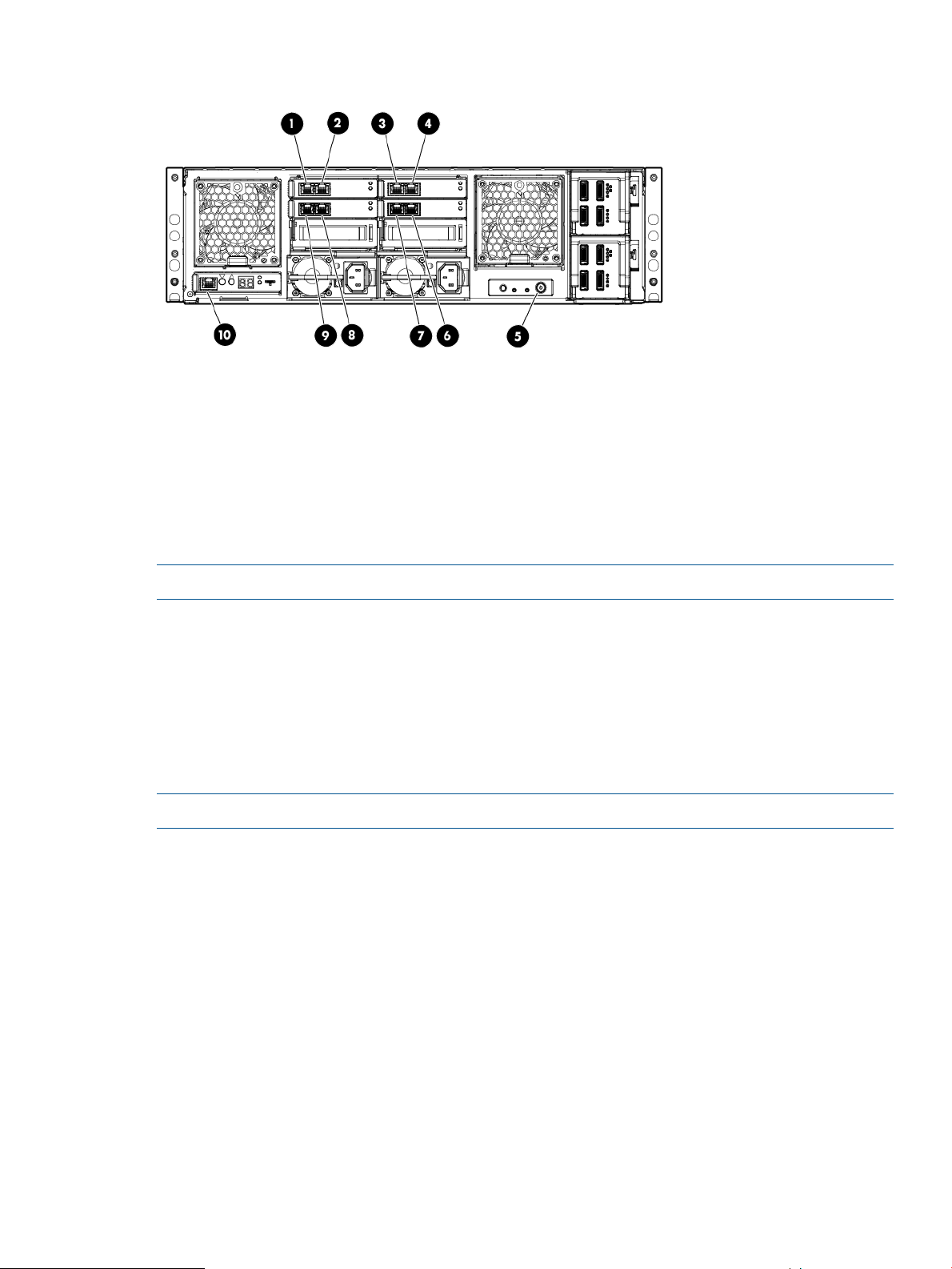
Figure 3 Network ports
5. E5000 enclosure power button
6. Server 2, Mezzanine NIC, port 21. Server 1, NIC port 1
7. Server 1, Mezzanine NIC, port 22. Server 2, NIC port 1
8. Server 2, Mezzanine NIC, port 13. Server 1, NIC port 2
9. Server 1, Mezzanine NIC, port 14. Server 2, NIC port 2
10. Enclosure Manager NIC (includes iLO connections for both
servers)
NOTE: E5300 Mezzanine NICs (6, 7, 8, and 9) are optional on E5300 servers.
For the initial configuration, the EMU port must be connected directly to the administrator's laptop
or PC, as described in “Configure the EMU and iLO management processors” (page 17).
The E5500 and E5700 enclosures have more NIC ports than the E5300 enclosure, and they
provide more network connection options. Figure 5 (page 13) shows the recommended management
network configuration.
While alternate network ports can be used for network-based backup, they can also be used for
EMU connectivity. As with the E5300, the Client/MAPI or Replication network can also be used
to establish EM network connectivity to the servers.
NOTE: NIC teaming is not recommended or supported with these interfaces.
By default, the E5000 Configuration Wizard sets up the following networks:
• Client/MAPI network
This network is labeled as the MAPI network on each server.◦
◦ The default setting is dynamic (DHCP), but you can use the E5000 Configuration Wizard
to configure static addressing.
• Replication network
◦ The E5000 Configuration Wizard automatically sets these static addresses by default
(but also allows you to change them):
– Server 1: 10.0.0.1
– Server 2: 10.0.0.2
Use the short Ethernet cable shipped with the messaging system to connect the Replication
network ports, as shown in Figure 4 (page 12) or Figure 5 (page 13).
Network connections 11
Page 12
• Management network
◦ The default setting is dynamic (DHCP) addressing, but you can change this setting as
needed.
◦ HP recommends that the management network be on the same network as the EMU and
iLO NIC port.
◦ This NIC is not standard on the E5300 model.
• Alternate network
◦ The default setting is dynamic (DHCP) addressing, but you can change this setting as
needed.
◦ This NIC is not standard on the E5300 model.
Figure 4 (page 12) shows the recommended E5300 network configuration expected by the E5000
Configuration Wizard described in “Configuring the messaging system software” (page 23).
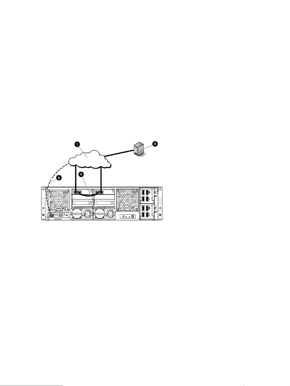
Figure 4 Recommended E5300 network configuration
1. Client/MAPI network
2. Replication network cable
3. Domain controller
4. Connection to EMU
Figure 5 (page 13) shows the typical E5500/5700 network configuration expected by the E5000
Configuration Wizard, as described in “Configuring the messaging system software” (page 23).
12 Preparing to install the messaging system
Page 13
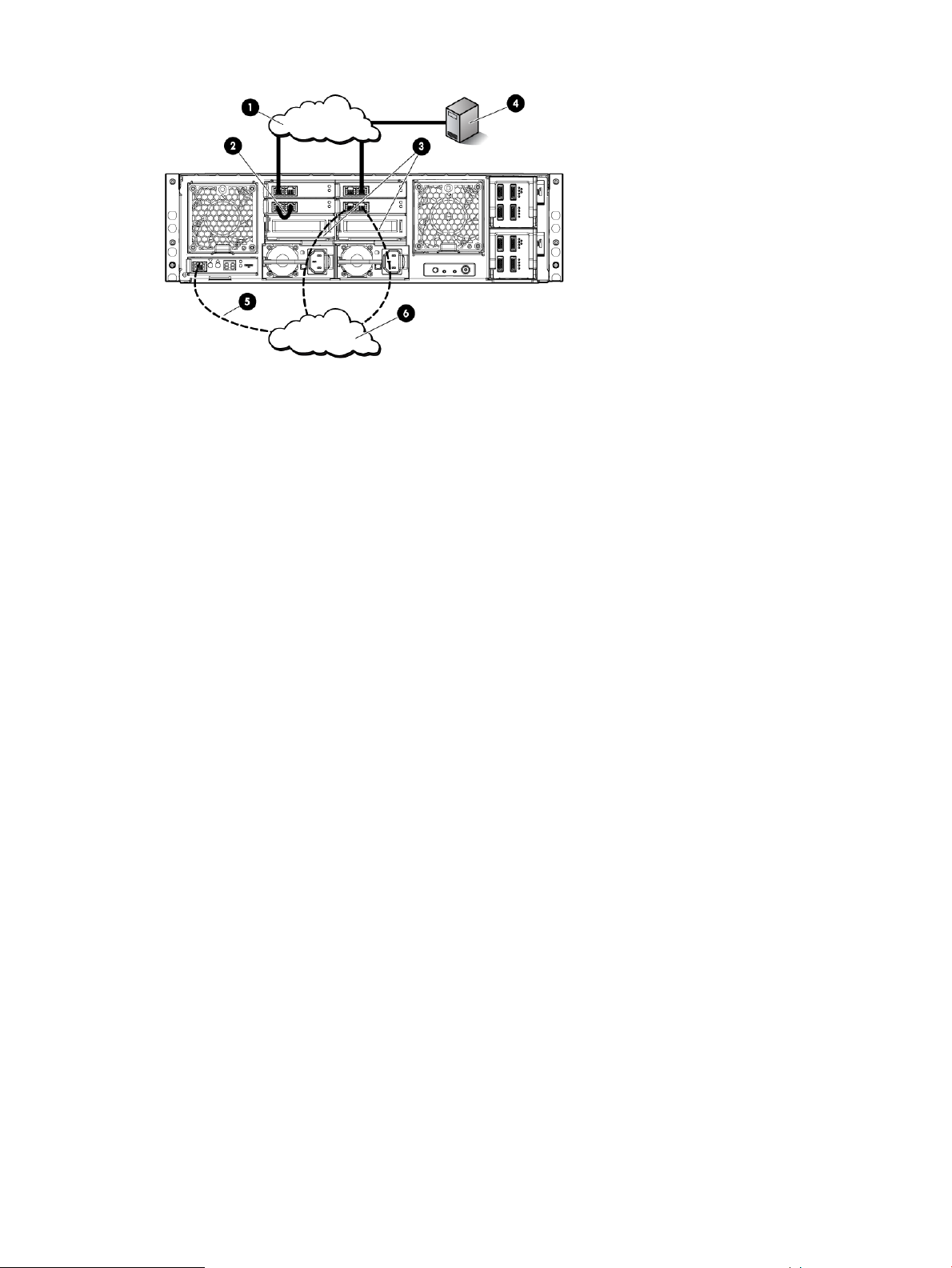
Figure 5 Typical E5500/5700 network configuration
4. Domain controller1. Client/MAPI network
5. Connection to EMU2. Replication network cable
6. Management network3. Connections to management network
Network connections 13
Page 14

3 Installing the messaging system
This chapter explains how to install the messaging system hardware.
Verify the kit contents
Remove the contents, ensuring that you have all of the following components. If components are
missing, contact HP technical support.
Hardware
• HP E5000 Messaging System base system configuration
• Expansion disk enclosures if deploying an E5700 configuration or if purchased as an upgrade
option for other configurations
• Rail kit
• Power cords
• Short CAT5 Ethernet cable
• 0.5m mini SAS cable and 2m mini SAS cable per external disk enclosure
Media and documentation
• HP ProLiant Essentials Integrated Lights-Out Advanced Pack
• End User License Agreement
• HP E5000 System Recovery DVD
• Certificate of Authenticity Card
• Safety and Disposal Documentation CD
Locate and record the product number, serial number, and SAID number
Before you begin installation, locate and record the product number of the messaging system,
serial number, and support contract service agreement ID (SAID) number.
The product number of the messaging system and serial number are located in three places:
• Top of the messaging system
• Back of the messaging system on a pull-out tab
• On the messaging system shipping box
The SAID number is listed on your service contract agreement (see “Obtaining the Service Agreement
ID” (page 60)).
Unpack and rack the messaging system hardware
WARNING! The messaging system enclosure is heavy. Always use at least two people to move
the messaging system into the rack.
14 Installing the messaging system
Page 15
1. If your messaging system is delivered in a rack, proceed to Step 2. If you ordered the messaging
system without the rack, install the rail kit and enclosure in the rack using the installation
instructions that are included with the rail kit.
IMPORTANT: Ensure that cabling in the back of the rack system does not interfere with
system operation or maintenance. Bind cables loosely with cable ties and route the excess
out of the way, along the side of the rack, to keep system components and indicators visible
and accessible.
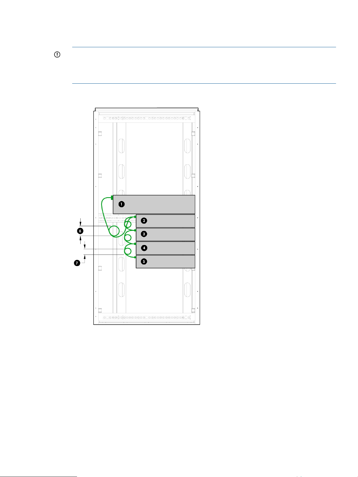
Figure 6 Messaging system installed in a rack
1. Messaging system enclosure
2-5. Expansion disk enclosures (optional)
6-7. Cable connection, with no bend radius smaller than 5 cm
2. If you purchased expansion disk enclosures, rack and cable the expansion disk enclosures
before moving to the next step. For recommended cabling, see “Cable expansion disk
enclosures” (page 16).
3. Cable the messaging system to your network and attach the power cords. See “Rear view”
(page 8) for connecting the power cables. For information on network configurations, see
“Preparing to install the messaging system” (page 10).
Unpack and rack the messaging system hardware 15
Page 16
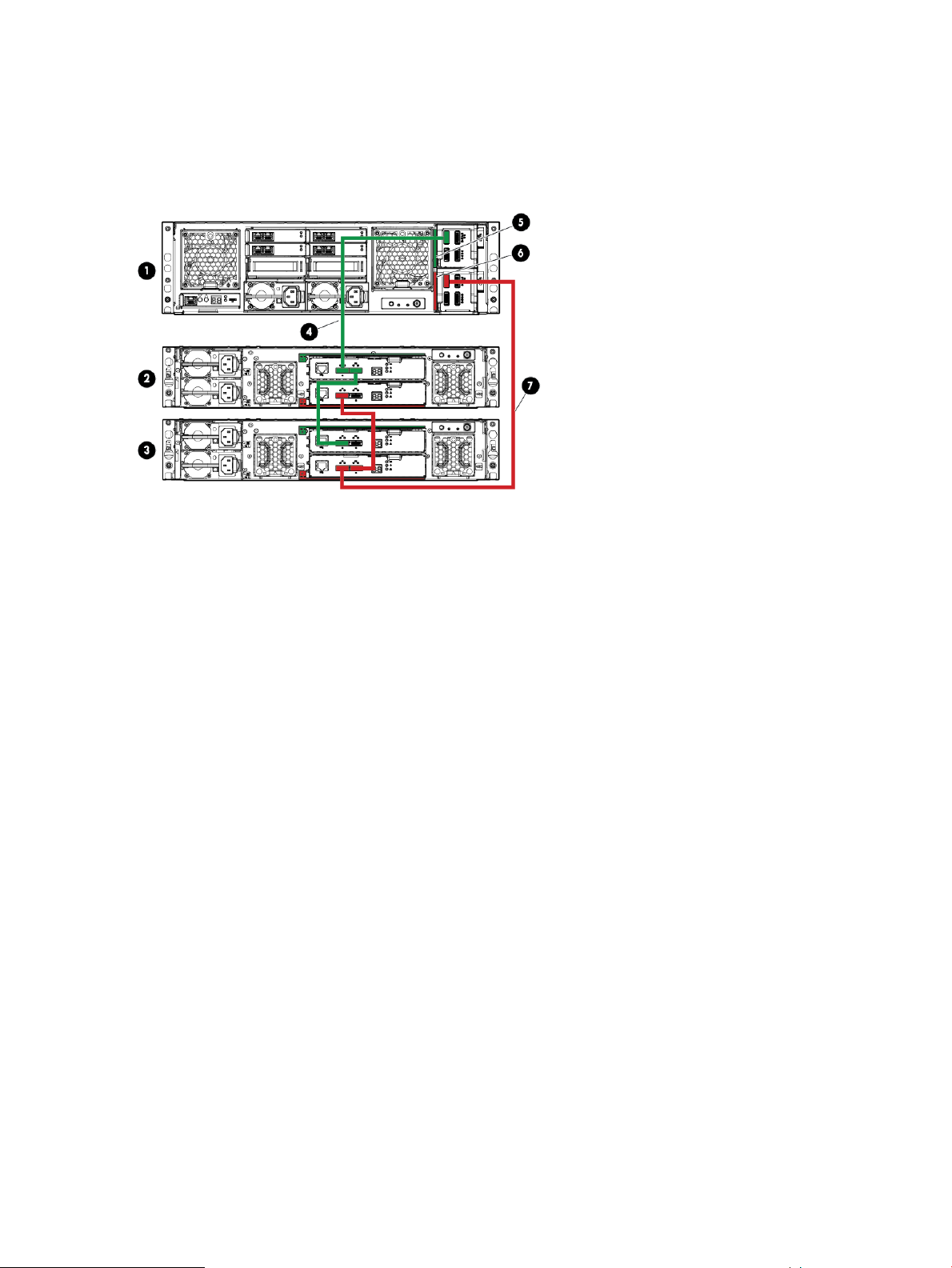
Cable expansion disk enclosures
The following figures show the correct cabling of expansion disk enclosures to the messaging
system chassis. Numbers represent the order of attachment. Figure 7 (page 16) shows an E5700
base configuration with two expansion disk enclosures.
Figure 7 E5700 base configuration with two expansion disk enclosures
1. E5700
2-3. Expansion disk enclosures
4. SAS cable connecting expansion disk enclosure 1 (green cable)
5. Green color code for upper SAS I/O module
6. Red color code for lower SAS I/O module
7. SAS cable connecting expansion disk enclosure 2 (red cable)
Figure 8 (page 17) shows an E5700 maximum configuration with four expansion disk enclosures.
16 Installing the messaging system
Page 17
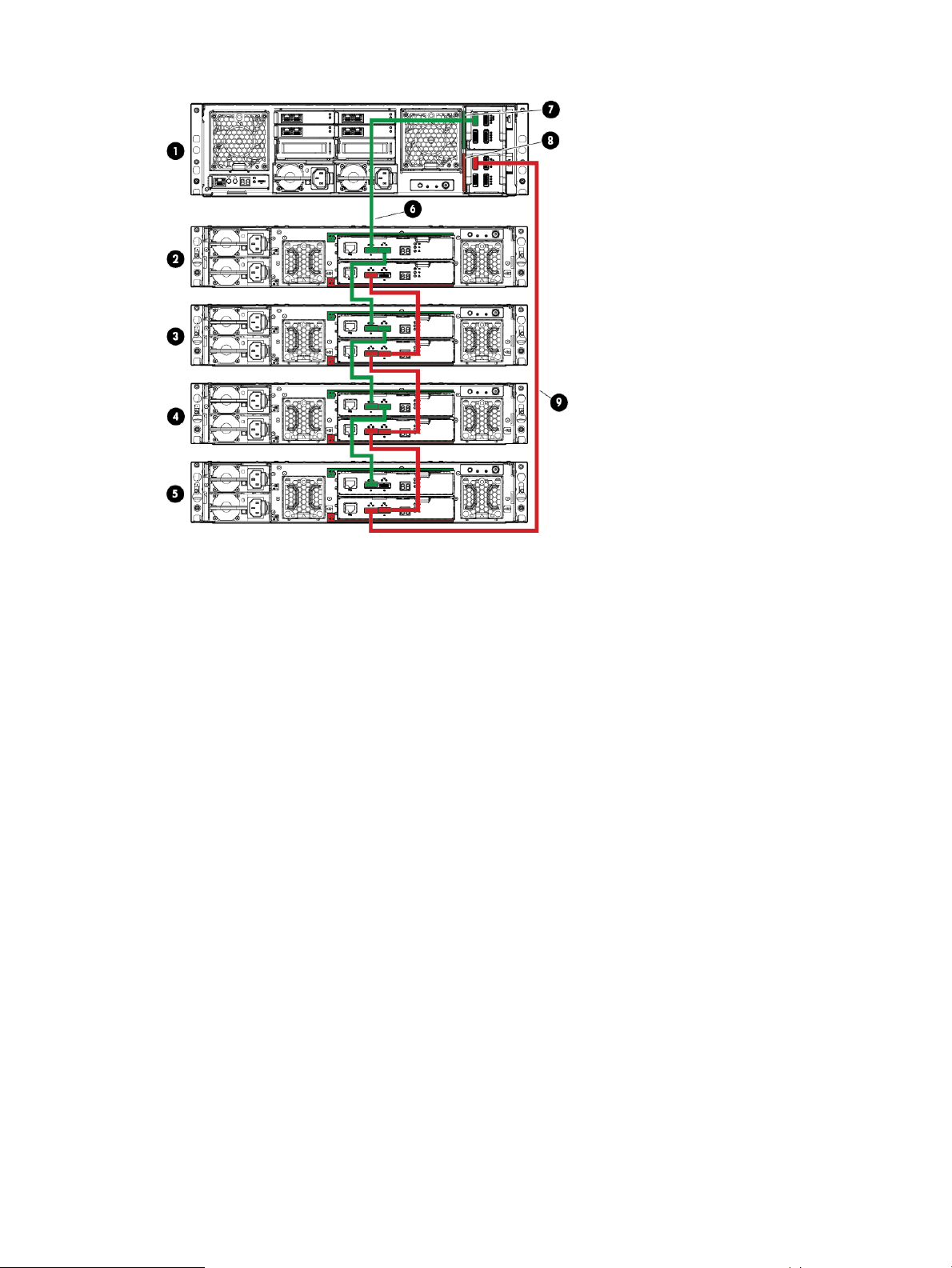
Figure 8 E5700 maximum configuration with four expansion disk enclosures
1. E5700
2–5. Expansion disk enclosures
6. SAS cable connecting expansion disk enclosure 1 (green cable)
7. Green color code for upper SAS I/O module
8. Red color code for lower SAS I/O module
9. SAS cable connecting expansion disk enclosure 2 (red cable)
Power on the messaging system
1. Power on any expansion disk enclosures.
2. Power on the messaging system by pushing the power button on the back of the chassis.
Once the messaging system power is on, power on the server blades if they do not
automatically power on.
Configure the EMU and iLO management processors
Before configuring the management processors, verify the following:
• You have determined whether the network ports on the server are to use DHCP or static
addresses. If the network ports are to use static addresses, you must provide the addresses.
• The server NIC ports are cabled to the appropriate switches or VLANs (see“Network
connections” (page 10)).
• For this step, the EMU port should not be connected to a switch. You can connect the EMU
port to a switch after the EMU and iLO NICs are configured.
Configure the EMU and iLO management processors for both servers as follows:
Power on the messaging system 17
Page 18
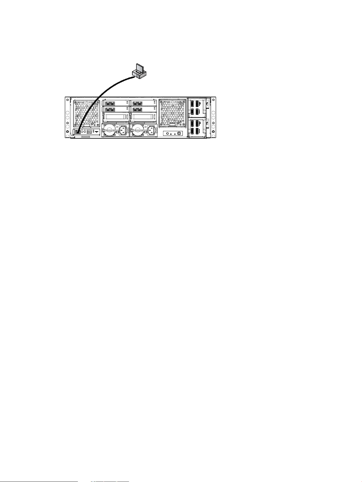
1. Connect a system (the configuration system) in the environment or a laptop to the EMU port
(Figure 9 (page 18)). You can use either a crossover or a regular Ethernet cable.
Figure 9 EMU NIC port connection
2. Configure the networking properties for the local system:
a. Open Control Panel, select Network Sharing Center or Network Connections, and navigate
to Local Area Connections.
b. Select Properties→Internet Protocol, and then select Properties.
c. If Use the following IP address: is selected, record values for the following items and
restore them after completing the EMU and iLO setup:
• IP address
• Subnet mask
• Default gateway
d. Enter the following values:
• IP address: 10.0.0.20
• Subnet mask: 255.255.255.0
e. Before continuing, ping the following IP addresses to test connectivity to the EMU and
the iLO located in each of the servers: 10.0.0.10, 10.0.0.11, and 10.0.0.12. The EMU
and iLO interfaces have been assigned IP addresses during factory setup. You must either
update the factory values with site-specific static IP addresses or configure the management
processors to use DHCP IP addressing.
3. Configure iLO on the server blades:
a. Open a web browser and log in to iLO using the address: http://10.0.0.11. You
are prompted to enter the user name and password. The password for the Administrator
account is located on a tear-away label on the back of the server blade (Figure 11
(page 19)).
After you have logged into iLO, HP recommends that you change the administrator
password. To do so, select User Administration under Administration in the iLO
management interface.
b. Configure the network as required for your environment. Select Network under
Administration in the iLO management interface. You can either enable DHCP or edit the
IP address details and enter site-specific network settings. Click Apply to save your settings.
c. Repeat the process on the other server blade. Open a web browser and log in to iLO
using the address: http://10.0.0.12.
18 Installing the messaging system
Page 19
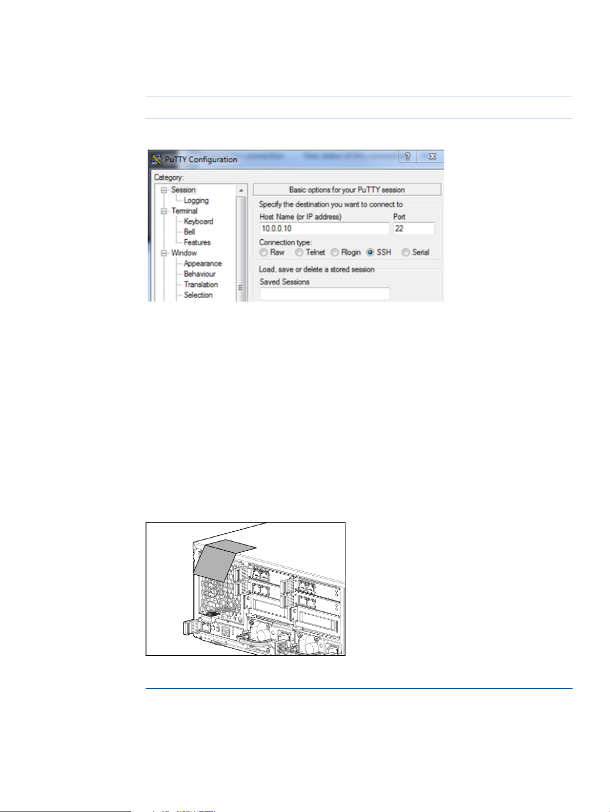
4. Configure the EMU:
a. Connect to the Enclosure Manager software using an ssh compatible tool like PuTTY. In
the PuTTY session basic options, enter the EMU IP address (10.0.0.10) and port (22),
and select SSH for the connection type (Figure 10 (page 19)).
NOTE: See “Managing the EMU” (page 134) for information on using CLI commands.
Figure 10 Connecting to the Enclosure Manager software
b. After you have connected to the EMU port, set the following attributes:
• EMU (DNS) name
• Rack name
• EMU password (located on the tear-away label on the back of the server blade; see
Figure 11 (page 19))
• IP addressing method
To change the static IP address, type the command set ipconfig static
◦
at the command line prompt and follow the instructions.
◦ To change the EMU addressing to DHCP, type set ipconfig dhcp at the
command line prompt.
Figure 11 Tear-away label location
Example 1 Setting attributes
CustomerEMU-dnsName> set em name CustomerEMU-dnsName
CSP Enclosure Manager name changed to CustomerEMU-dnsName.
CustomerEMU-dnsName> set rack name CustomerRackName
Changed rack name to "CustomerRackName".
Configure the EMU and iLO management processors 19
Page 20

CustomerEMU-dnsName> set password
New Password: ********
Confirm : ********
Changed password for the "Administrator" user account.
CustomerEMU-dnsName>
NOTE: You will not be able to connect to iLO or the EMU from the configuration system until
you change the network settings on the configuration system.
5. Complete the configuration:
a. Connect the EMU port to the appropriate switch/VLAN/subnet.
b. Log in to the EMU using ssh and the newly assigned EMU name and validate connectivity.
It is assumed that the EMU name is in the DNS.
Example 2 Verifying connectivity
CustomerEMU-dnsName> show server list all
Bay iLO Name iLO IP Address Status Power UID
--- ----------------------------- --------------- -------- ------- -- 1 ILOMXQ0110FJ9 16.78.90.51 OK On Off
2 ILOMXQ0110FHU 16.78.90.113 OK On Off
Totals: 2 server blades installed, 2 powered on.
Accessing the messaging system
For initial messaging system configuration you must have console access for each of the server
blades. You can use either a local I/O diagnostic (SUV) cable or an iLO connection. The iLO
connection is the preferred method because it allows for remote access.
For remote access, open a web browser and enter the iLO name or IP address for the server blade
located in Bay 1. For more information about IP addressing and subnets, see “Network connections”
(page 10). Log in using the iLO administrator name and newly created password for that blade.
For instructions on using iLO, see the Integrated Lights Out user guide available from http://
www.hp.com/go/ilo. On the iLO web page, select More iLO Documentation.
If you are using the direct connect method, connect the supplied SUV cable to the front of the
messaging system server blades in the following sequence: keyboard, mouse, monitor cable, and
monitor power cable.
NOTE: The keyboard, mouse, and monitor are not provided with the messaging system.
20 Installing the messaging system
Page 21
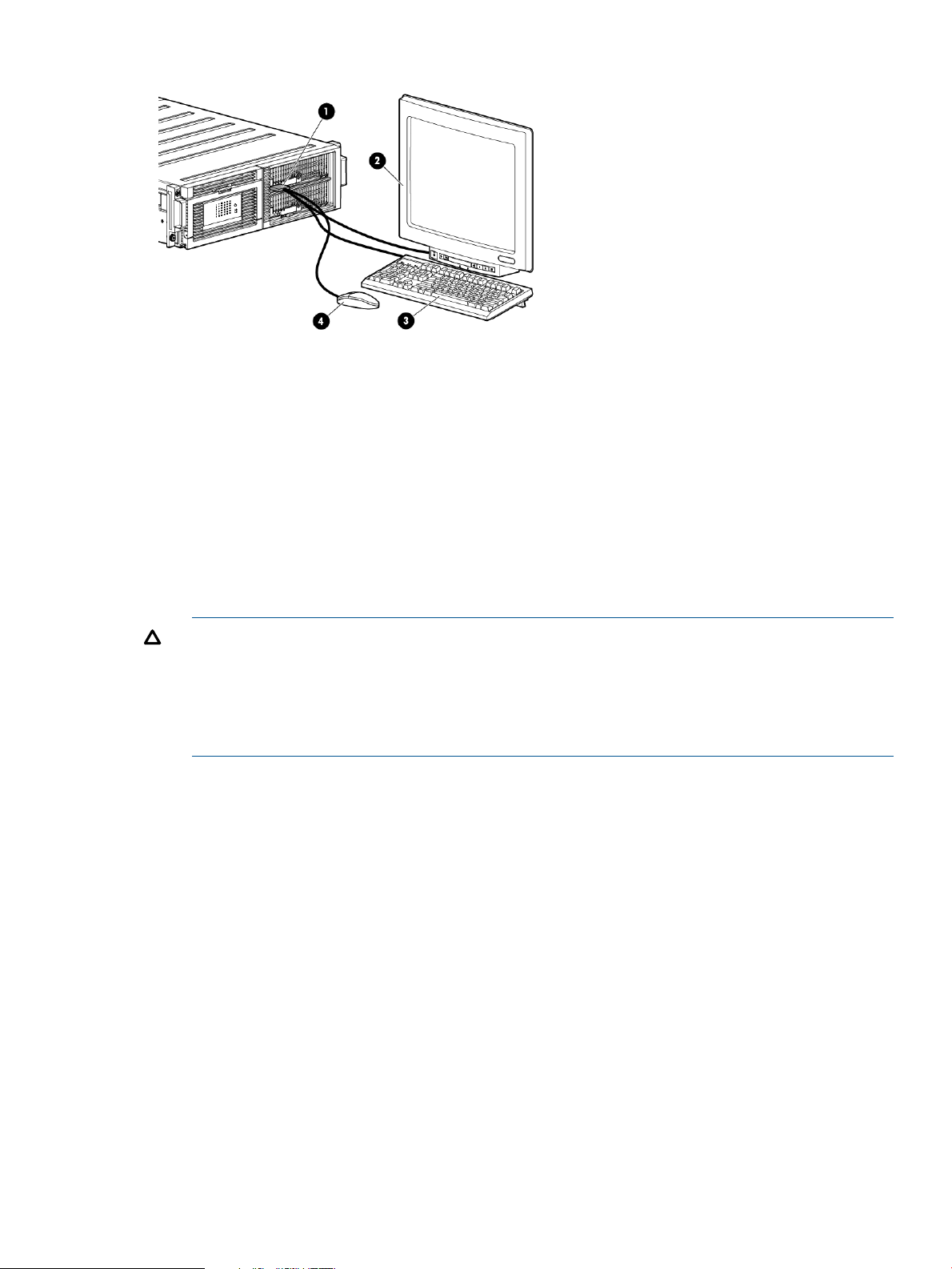
Figure 12 Keyboard, mouse, and monitor
1. Messaging system enclosure
2. Monitor
3. Keyboard
4. Mouse
Adding expansion disk enclosures to an installed messaging system
1. Rack the expansion disk enclosures.
2. Use the Exchange Management Console or the Exchange Management Shell to failover the
databases from the Bay 1 server to the Bay 2 server.
3. Power on the expansion disk enclosures.
CAUTION: In some cases, when adding new expansion disk enclosures, disks are seen
through a single path. This condition is reported as an error in the diagnostics initially performed
by the E5000 Configuration Wizard. To fix this problem, power cycle the expansion disk
enclosures by pressing and holding the button on the back of the unit, then pressing and
holding the button once again to power them back on. Then run the E5000 Configuration
Wizard from the All Programs shortcut.
For instructions, see “Configuring server software” (page 23).
The messaging system identifies the new storage and creates new LUNs.
4. Once the E5000 Configuration Wizard has completed, on the Bay 2 server, use the Exchange
Management Console or the Exchange Management Shell to manually failover the databases
from the Bay 2 server to the Bay 1 server.
5. Rebalance the databases using the RedistributeActiveDatabases.ps1 script located
(by default) at \Program Files\Microsoft\Exchange Server\V14\scripts. Run
this script within the Exchange Management Console.
6. Within the Microsoft Exchange Management Console, select New Mailbox Database:
a. Name the new database the next item in the sequence (for example, DB10).
b. Select a server.
c. Set the path based on the newly created LUNs.
7. Use Microsoft Exchange Management Console to add a mailbox copy.
Adding hard drives to an installed E5000 system
If you are running an E5000 system with fewer than the maximum number of hard drives, you can
add drives as follows:
1. Install the new drives as described in “Replacing the drive drawer hard drive” (page 106).
Adding expansion disk enclosures to an installed messaging system 21
Page 22

2. Run the E5000 Configuration Wizard on the first server manually from the All Programs
shortcut. The wizard recognizes the new storage and creates new LUNs. Exit the wizard at
the first opportunity.
3. Run the wizard on the second server.
4. Within the Microsoft Exchange Management Console, select New mailbox database and
name the new database sequentially. For example, if the previous database name is DB9,
name the new database DB10. After naming the new database, complete the following steps:
a. Select a server.
b. Set the path based on the newly created LUNs.
5. Use Microsoft Exchange Management Console to add a mailbox copy on the other server.
22 Installing the messaging system
Page 23

4 Configuring the messaging system software
This chapter explains how to configure system software using the E5000 Configuration Wizard
and how to deploy Microsoft Exchange Server 2010 using the E5000 Exchange Deployment Tool.
IMPORTANT: To configure the messaging system, you must run these tools on each server blade.
HP recommends that you fully complete the E5000 Configuration Wizard and E5000 Exchange
Deployment Tool on the Bay 1 server blade before beginning to configure the Bay 2 server blade.
After you have completed the initial configuration, be sure to install any available software updates
as described in “Upgrading E5000 software” (page 61).
Configuring server software
The E5000 should be powered on and the network ports cabled for your network configuration,
including the EMU port. For configurations that use expansion disk enclosures, such as the E5700,
all expansion disk enclosures should be cabled to the messaging system and powered on. Complete
the following steps, first on server 1, and then on server 2. Do not start on the second server until
you have completed the steps on server 1. When the server is powered on for the first time, it
completes the initial Windows configuration process and then launches the E5000 Configuration
Wizard.
To configure the software:
1. Enter your locale information in the Windows setup dialog box and accept the license terms.
The Windows setup completes in approximately 15 minutes and the server reboots. Upon
reboot, the server automatically logs on with the default password (HPinvent!) and the E5000
Configuration Wizard starts. After reading the welcome screen, click Next.
NOTE: If the automatic logon does not occur and a message displays that the user name
or password is incorrect, re-enter Administrator as the user name and HPinvent! as
the password to complete the logon and start the E5000 Configuration Wizard.
2. Set and confirm the server Administrator password. The Administrator password is required
only the first time you run the wizard. Click Next.
NOTE: The Windows Server 2008 R2 default password policy requires a strong password
as the server password for each server on the E5000 Messaging System. For more information
on strong passwords for Windows Server 2008 R2, see the following Microsoft Technet article:
http://technet.microsoft.com/en-us/library/cc736605(WS.10).aspx
3. Set the network configuration. Review each network port configuration and either accept the
default values or click Edit to change them. Click Next when finished.
Configuring server software 23
Page 24
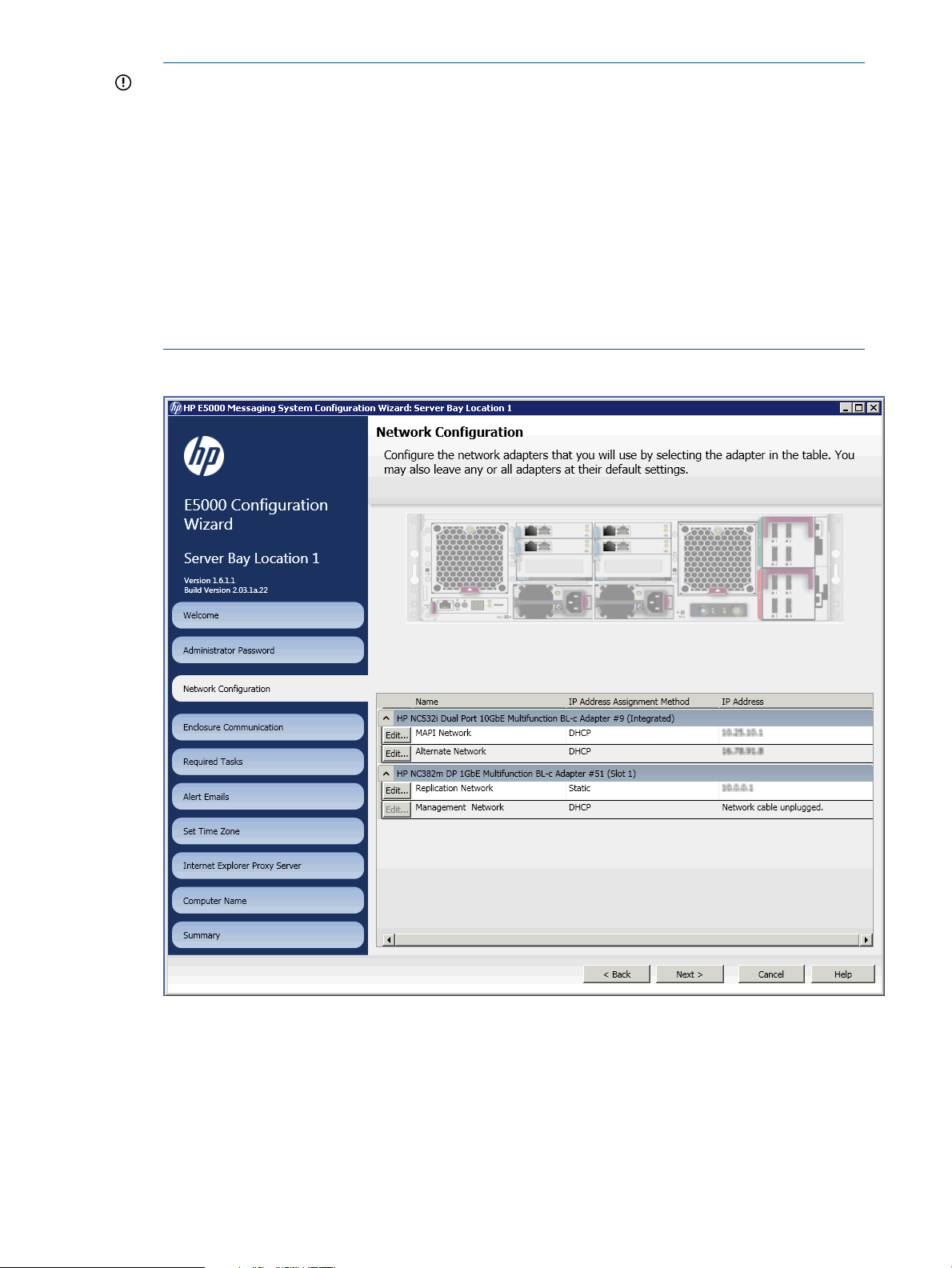
IMPORTANT:
• By default, the Replication network is set to a static network (10.0.0.0/30) with IP
10.0.0.1 on the first node and 10.0.0.2 on the second node. A cable directly connects
the two ports. If these addresses conflict with addresses on your network, reconfigure
them to some other unused static network. If the replication ports will be connected to a
switch, you might have to change the network settings. You can either automatically
configure with DHCP or manually enter a specific IP address.
• Be careful not to put the Client/MAPI and Replication networks on the same subnet. If
you attempt to do so, the wizard displays a warning.
Figure 13 (page 24) shows an E5500/5700 configuration that has four networks per server:
Client/MAPI, Replication, Management, and Alternate. The E5300 configuration has two
(standard) networks per server: Client/MAPI and Replication.
Figure 13 Network configuration
4. Enter the EMU Administrator password and then click Next.
The default password is printed on a label attached to the underside on the EMU module. The
default password is also printed on a tear-away label attached to the rear of the enclosure
(Figure 11 (page 19)). Remove the tear-away label and store it in a safe place. After you
enter the password, an animated icon indicates that the wizard is verifying connection to the
enclosure.
24 Configuring the messaging system software
Page 25
5. The wizard displays the status of tasks it must complete before continuing. If the wizard finds
errors, it reports them and stops. You must exit the wizard, fix the errors and restart the wizard
from the All Programs menu on your system.
NOTE: If the wizard reports fan warnings, replace the fan module as soon as possible.
6. Configure Alerts and Email to send email notification of system events (see “Configuring Alerts
and Email” (page 34)).
7. Set the time zone and then click Next. The correct local time zone is set when the server joins
a domain.
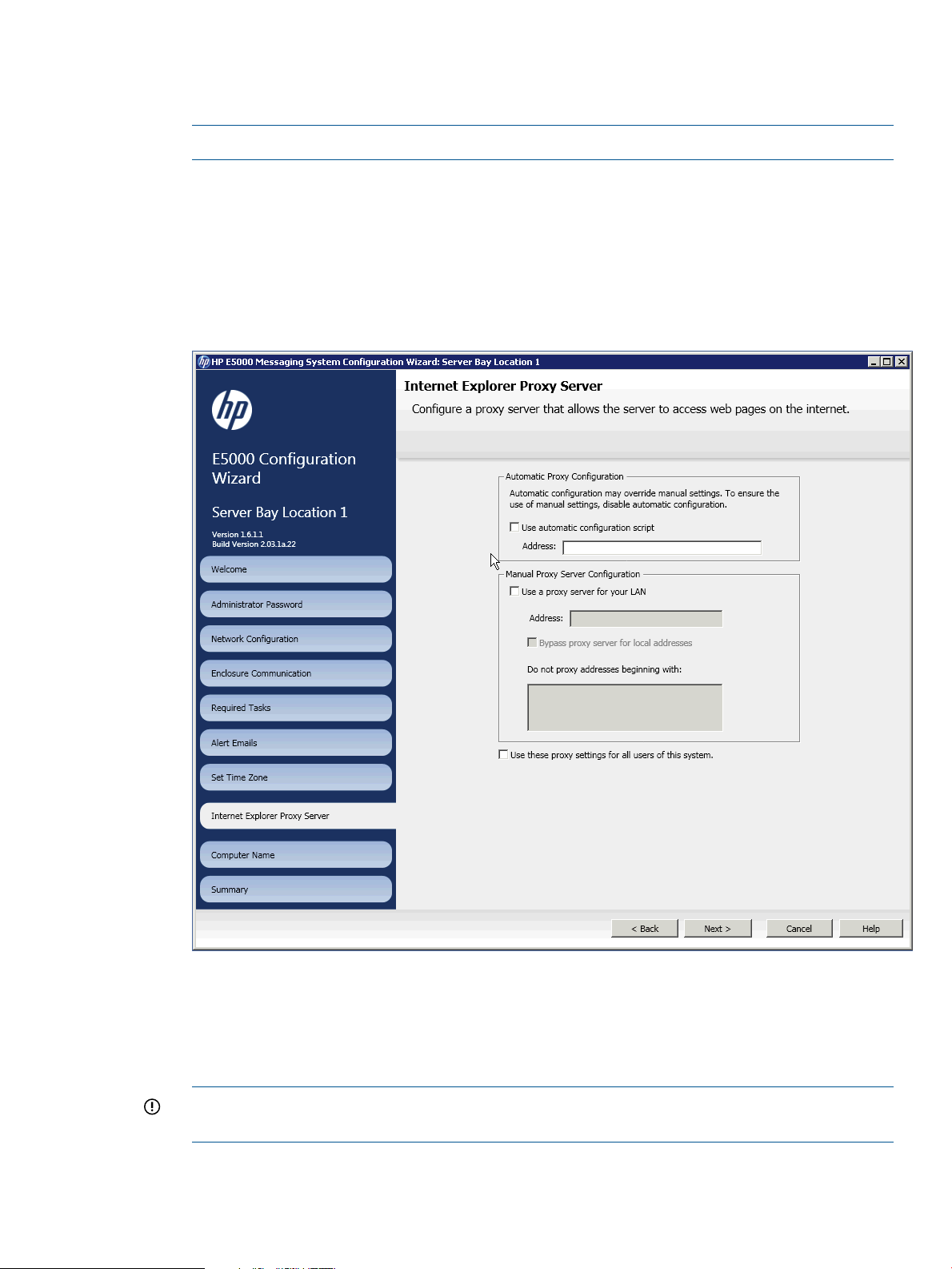
8. Configure the Internet Explorer Proxy Server settings (see Figure 14 (page 25)) and then click
Next.
Figure 14 Internet Explorer proxy server
9. Set the computer name and join a domain (see Figure 15 (page 26)). Enter the computer
name and the name of the domain that the computer will join. Enter the name and password
of a user (typically Administrator) who has permission to add the computer to the domain.
The Administrator password is required only the first time you run the wizard. Click Next when
finished.
IMPORTANT: Be sure to record the name of the first server. You will need that name when
you configure the second server.
Configuring server software 25
Page 26
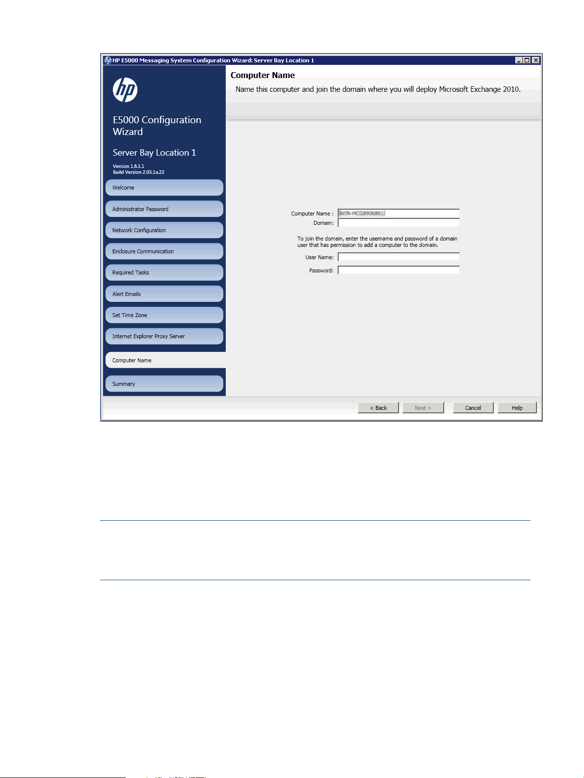
Figure 15 Computer name
10. Review the summary report and complete the configuration. The Summary screen lists the
configuration settings you have made.
11. Click Apply Settings to apply the configuration settings or Back to modify them. When you
are ready to accept the settings, click Finish to reboot the server. If you do not want to reboot
at this time, clear the Reboot after exiting the wizard box. The server must be rebooted to join
the domain and is also a required step prior to deploying Microsoft Exchange Server 2010.
NOTE: The server blades contain redundant storage controllers. When a server reboots,
one of the controllers shuts down. The partner server sees this event as a redundancy loss and
creates a log entry: “drive array controllers are no longer redundant”. You can ignore the
message if it coincides with a reboot you initiated.
Continue with the next procedure, “Deploying Microsoft Exchange Server 2010” (page 26), and
complete the setup on the Bay 1 server before setting up the Bay 2 server.
Deploying Microsoft Exchange Server 2010
Follow this procedure to deploy Microsoft Exchange Server 2010. Complete the deployment of
Microsoft Exchange Server 2010 on the Bay 1 server blade before beginning the configuration
of the Bay 2 server blade.
26 Configuring the messaging system software
Page 27
IMPORTANT: Before proceeding:
• Install any available software updates as described in “Upgrading E5000 software” (page 61).
• Ensure that the Active Directory and domains have been configured. For more information,
see http://technet.microsoft.com/en-us/library/bb125224.aspx. You must also provide a
witness server to be used by the DAG. For details on selecting and configuring a server to be
a witness server, see http://technet.microsoft.com/en-us/library/dd351107.aspx .
1. Log in to the Bay 1 server. If you have completed this procedure for the Bay 1 server, log in
to the Bay 2 server now.
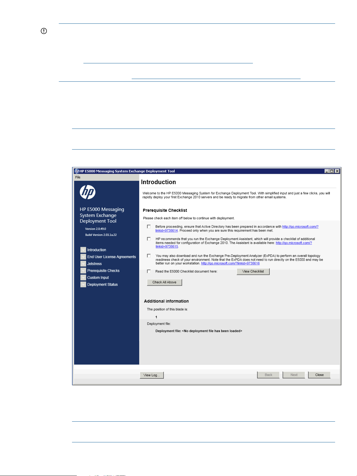
When you log in, the Windows Security screen appears. Log in using the domain administrator
credentials you used to join the server to the domain. The E5000 Exchange Deployment Tool
starts automatically and displays the Introduction window.
NOTE: If you do not log in as the domain administrator, the E5000 Exchange Deployment
Tool will not run. You must log out and log in as the domain administrator.
Figure 16 Deployment introduction
HP recommends that you run the tests in the Prerequisites checklist. For detailed information
on Microsoft prerequisites, visit the links displayed on Figure 16 (page 27).
After you have run the tests, click Next.
NOTE: You need a properly configured Internet Explorer browser, including proxy
configuration (if applicable), to access the links.
Deploying Microsoft Exchange Server 2010 27
Page 28
2. The End User License Agreement Confirmation screen appears. After reading and accepting
the agreements, click Next.
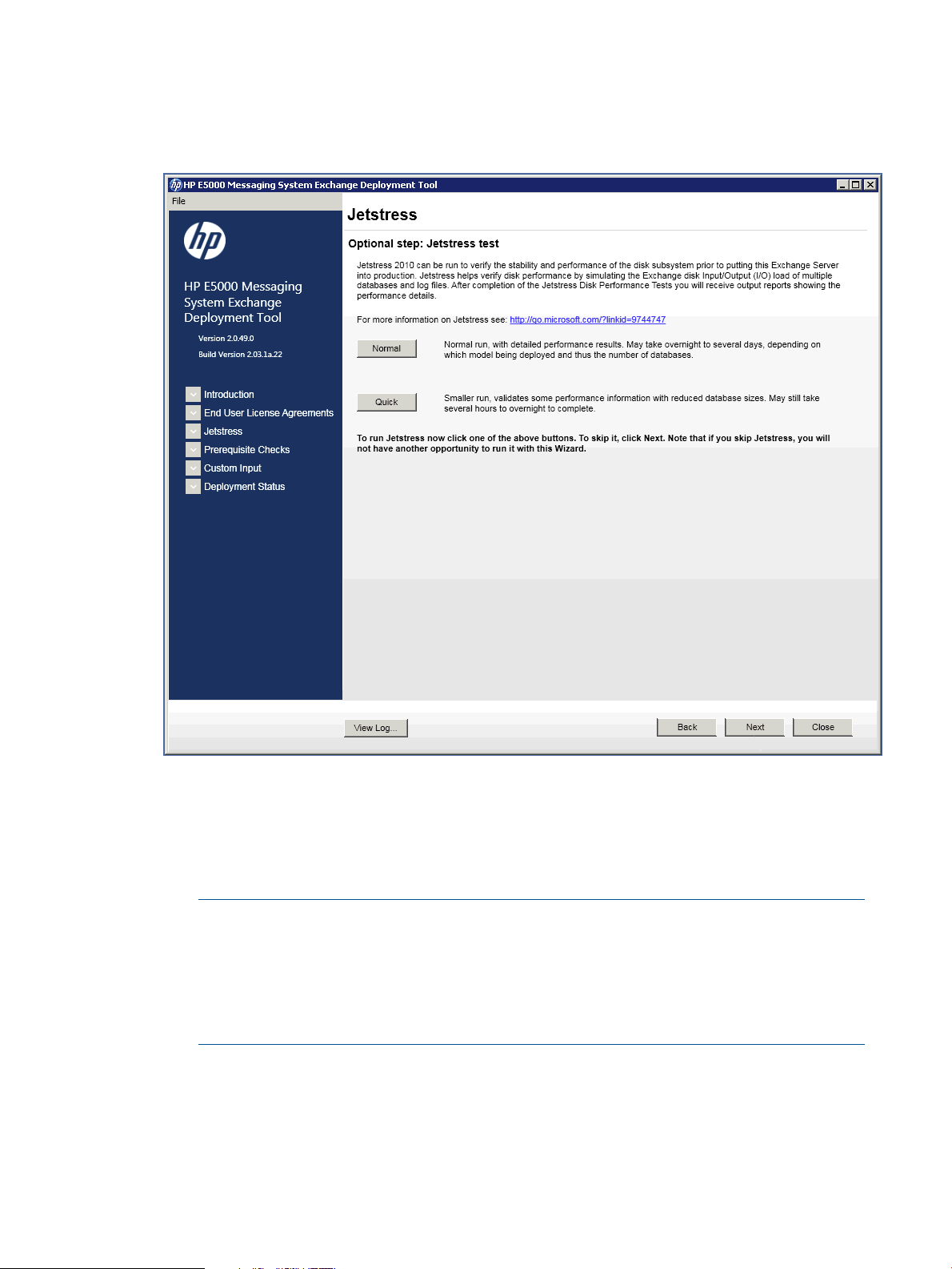
The Jetstress screen appears (Figure 17 (page 28)):
Figure 17 Jetstress Tools
3. If you choose to run a Jetstress test, select the type of Jetstress test. The default is set to skip
Jetstress (click Next to skip the test).
• A normal run of the Jetstress test provides a baseline benchmark of the system. HP
recommends that you run the test now, but only if you have sufficient time before deploying
the server into production.
NOTE:
◦ A normal run of the Jetstress test can take 24 hours to complete.
◦ Until the Exchange Deployment Tool is run on the final node, the system configuration
is listed as unsupported in the system tray. Ignore the system tray status until Exchange
has been deployed on all nodes.
• A quick run of the Jetstress test does not provide detail performance results but can be
used to validate some of the configuration information.
Choose a quick run if you cannot dedicate the time for a normal Jetstress test. For more
information about Jetstress, see “Using Microsoft Exchange Jetstress and Load Generator
(optional)” (page 32).
28 Configuring the messaging system software
Page 29
Once you make a selection or if you choose to skip the Jetstress test, click Next. The
Prerequisite Checks screen appears (Figure 18 (page 29)).
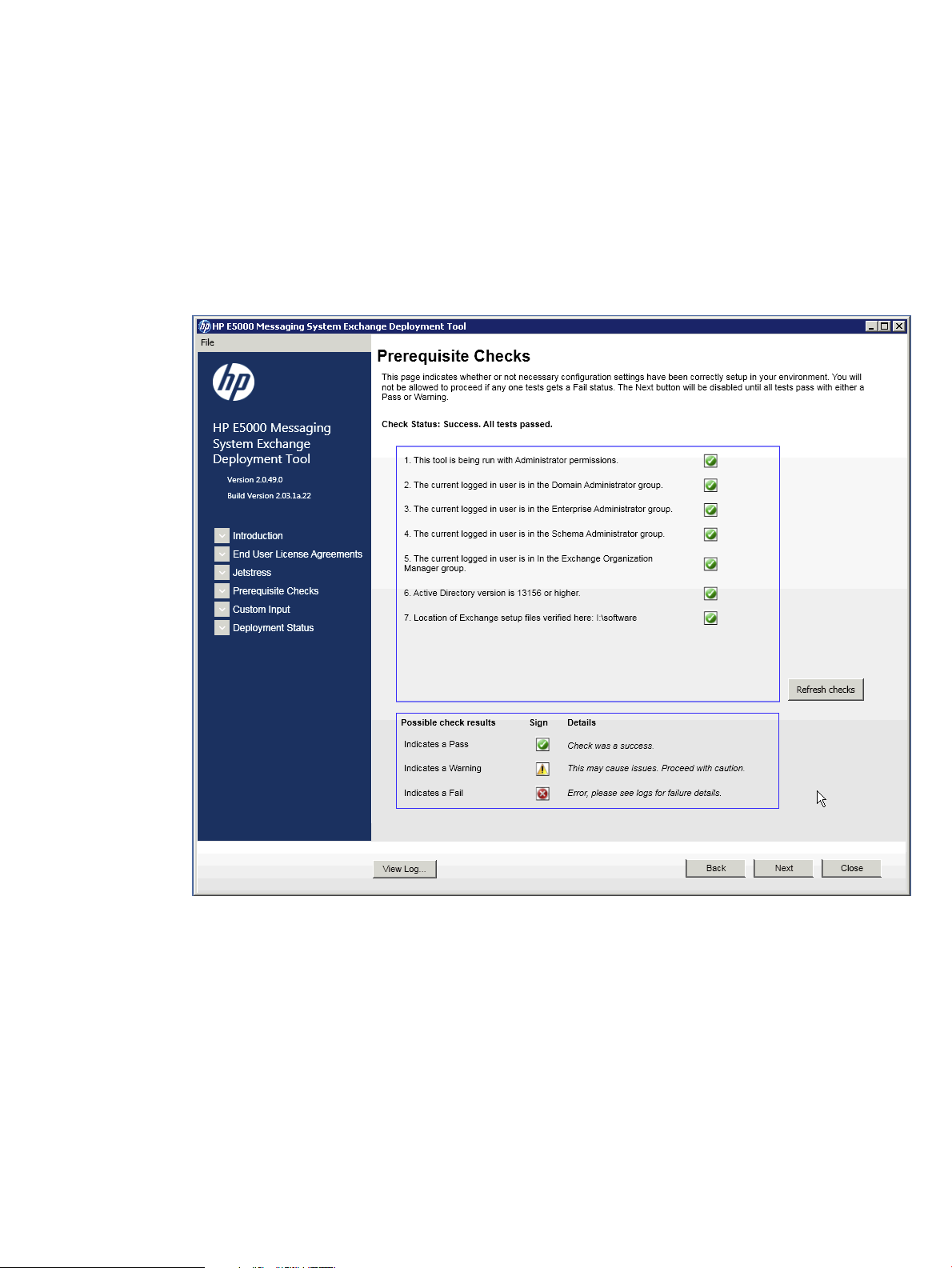
4. The Prerequisite Checks screen displays the status check results for the configuration settings
in your environment.
If a test fails, the Next button is disabled and you are not allowed to proceed. Check the logs
for the configuration setting failure details and correct the failed setting. Click Refresh checks
to verify the settings.
If all tests pass with either a green checkmark or warning, the Next button is enabled. Click
Next to start deployment of the Exchange Administration Tools.
Figure 18 Prerequisite Checks
5. After the installation of the Exchange Administration Tools finishes, complete the fields on the
Custom Input window.
When deploying to the Bay 1 server, select First blade. The E5000 Exchange Deployment
Tool automatically detects whether any servers are found in the existing Exchange organization
(when existing is selected). When deploying to the Bay 2 server, select Second blade. The
name of the second blade of Bay 1 server is autodetected.
Complete each item on this screen as needed for your deployment:
• New or existing Availability Group (DAG) name. The E5000 Exchange Deployment Tool
automatically detects if any DAGs are found in the existing Exchange organization.
Accept the default name or enter a new name of a DAG that already exists.
• Availability Group IP address. Using an IP address of 0.0.0.0 configures the DAG to use
DHCP. You can update the configured IP address later using the Exchange Management
Deploying Microsoft Exchange Server 2010 29
Page 30

Shell, or additional addresses can be added later using the Set-AvailabilityGroup
PowerShell command.
• Witness server name. See http://technet.microsoft.com/en-us/library/dd351107.aspx
for information about special considerations if placing the suggested default witness server
on a domain controller.
• Witness directory. Specify the local path on the witness server.
• Name prefix. Use the suggested default name or enter a new name. The E5000 Exchange
Deployment Tool appends numbers to the name and verifies that the name is unique at
the organization level (an Exchange 2010 requirement).
• Client Access Server (CAS) is Internet facing. For more information, see http://
technet.microsoft.com/en-us/library/dd351198.aspx .
• New or Existing CAS array. If a new array, enter a name or select from the dropdown
list for existing arrays (if detected).
• Enter the name of your load-balanced CAS array that is set on the database property. If
no load-balanced CAS array is available, see:
◦ http://go.microsoft.com/?linkid=9738617
◦ http://go.microsoft.com/?linkid=9738618
• Enable Error Reporting. For more information, see http://go.microsoft.com/?
linkid=9738619.
• Create Public Folder database. To connect to Exchange 2010 Microsoft Entourage or
Outlook 2003, clients require a public folder database. The E5000 Exchange Deployment
Tool runs Exchange setup to create the public folder database for you. This option is
available only on the first Exchange 2010 Mailbox server being deployed. The public
folders on this system are designed primarily for Free-Busy usage and not large-scale
folder replicas or other applications. The database is created in
h:\ExchangeDatabases\PF\Exch2010PublicFolder.edb.
• Exchange 2003 bridgehead server. Use the parameter to specify an Exchange 2003
bridgehead server that is located in the routing group to which you plan to create the
initial routing group connector. A routing group connector is required for mail flow
between Exchange 2010 and Exchange 2003 when these Exchange server versions
coexist in the same organization.
• Customer Experience Improvement Program. See http://go.microsoft.com/?
linkid=9738620.
6. Click Deploy to start the tools deployment process. This process typically requires about 1
hour and 30 minutes.
The E5000 Exchange Deployment Tool displays the Deployment Status window (Figure 19
(page 31)).
30 Configuring the messaging system software
Page 31

Figure 19 Deployment status
When the process completes, you are prompted to reboot the server. After the reboot, log in
again with Exchange administrator credentials (see http://technet.microsoft.com/en-us/library/
ee681663.aspx) to complete the deployment (the E5000 Exchange Deployment Tool reappears
automatically when you log in).
7. After deployment completes, the E5000 Exchange Deployment Tool displays a success message
and prompts you to run the Microsoft Exchange Best Practices Analyzer.
IMPORTANT: HP recommends that you do not run the Analyzer until the E5000 Exchange
Deployment Tool completes on the second server. Complete the E5000 Configuration Wizard
and the E5000 Exchange Deployment Tool on the Bay 2 server now before continuing.
Deploying Microsoft Exchange Server 2010 31
Page 32

8. After Microsoft Exchange is deployed on the Bay 2 server, accept the prompt to run the
Analyzer. The Microsoft Exchange Best Practices Analyzer window appears.
Figure 20 Microsoft Exchange Best practices analyzer
The Analyzer is located in the Toolbox node in the Exchange Management Console. You can
use the Analyzer to connect to Active Directory, start a scan, and perform other Exchange
operations.
For more information about Microsoft Exchange Server 2010 and to download the complete
help file, see Exchange Server 2010 at http://technet.microsoft.com/en-us/library/
bb124558.aspx.
Next steps
The messaging system is now installed and configured in a DAG with the number of database
copies you have specified.
HP strongly recommends that you also install Insight Remote Support as described in “HP Insight
Remote Support software” (page 58).
Using Microsoft Exchange Jetstress and Load Generator (optional)
You can use Microsoft Exchange Jetstress and Load Generator (LoadGen) to generate a simulated
Exchange workload on your system and analyze the effect of that workload on the messaging
system.
CAUTION: You must run these tools in a nonproduction environment to avoid potential loss of
data and performance degradation.
For more information about these tools, see Tools for Performance and Scalability Evaluation at
http://technet.microsoft.com/en-us/library/dd335108.aspx. If you are testing Jetstress, only the
E5000 servers are required. The servers must not have Exchange loaded when running Jetstress.
When running LoadGen, Exchange Server 2010 SP1 is installed on both servers in the E5000
enclosure, and the Client Access Server, Hub Transport Server, and Mailbox Server roles are
installed. Because multiple roles are installed on both servers, and because of the participation of
32 Configuring the messaging system software
Page 33

each server in the DAG, you must use an external load balancing method. Two possible methods
are:
• Use a hardware load balancer.
• Use the Exchange database configuration to balance the load across the CAS servers manually.
◦ MAPI Traffic: Assuming the users are evenly split between databases, use the
Set-MailboxDatabase cmdlet available from Microsoft at http://technet.microsoft.com/
en-us/library/bb123971.aspx and specify the rpcclientaccessserver parameter
equal to cas1 for half of the databases and cas2 for the other half.
◦ OWA Traffic: OWA requires persistence, so direct all OWA traffic through the first CAS.
◦ Exchange Sync (EAS): Direct all OWA traffic through the second CAS.
◦ Other protocols (POP3, IMAP, and so forth): Use DNS round-robin to get rudimentary
load balancing.
Using Microsoft Exchange Jetstress and Load Generator (optional) 33
Page 34

5 Monitoring and troubleshooting the messaging system
The messaging system provides several monitoring and troubleshooting options. You can access
the following troubleshooting alerts and solutions to maintain the system health:
• Notification alerts
• System Management Homepage (SMH)
• System Manager
• Hardware component LEDs
• EMU CLI SHOW commands
• HP and Microsoft support websites
• HP Insight Remote Support software
• Microsoft Systems Center Operations Manager (SCOM) and Microsoft websites
• HP SIM 6.3 or later is required for proper messaging system/HP SIM integration.
NOTE: Integration with HP SIM is only supported using the WBEM/WMI interfaces. Do not
attempt to configure HP SIM to use the ProLiant SNMP agents, because the configuration is
untested and unsupported. The ProLiant SNMP agents are enabled on the messaging system
by default and should not be disabled as they are used for internal management functions. If
they are enabled for external client consumption, HP SIM must be configured so it does not
attempt to communicate with these agents.
NOTE: WBEM events for storage are logged into Windows Application logs and WBEM events
for Server and Enclosure are logged into Windows System logs.
If you are unable to resolve a messaging system operation issue after using the various options,
contact HP Support. You must provide your SAID and your warranty and entitlement labels. See
“Obtaining the Service Agreement ID” (page 60) and “Locating the messaging system warranty
entitlement label” (page 60).
Using notification alerts
When you receive an alert, open the System Manager (described in “Using the System Manager”
(page 42)) to view a high-level description of the issue. You may then choose to open the System
Management Homepage or HP SIM to obtain more detailed information.
IMPORTANT: While the notification alerts report issues as they arise, it is still important to monitor
the messaging system regularly to ensure optimal operation.
See “Troubleshooting” (page 176) and “E5000 Error Codes” (page 164) for troubleshooting
information.
Configuring Alerts and Email
Configure Alerts and Email in the System Manager to send email notification of system events.
IMPORTANT: HP recommends that you configure Alerts and Email (and also install HP Insight
Remote Support) to ensure that you are proactively alerted to issues. Proactive notification enables
you to address issues before they become serious problems.
To create an alert for a recipient:
1. Open the Server Manager by clicking the icon located to the right of the Start button on the
Windows taskbar.
34 Monitoring and troubleshooting the messaging system
Page 35

2. Expand the tree under System Manager.
3. In the tree, select Alerts and Email.
Figure 21 Configuring Alerts and Email
4. Do one of the following:
• Select New to create a profile.
• Select Copy or Edit to modify an existing profile.
The Alert Settings window appears.
Configuring Alerts and Email 35
Page 36

Figure 22 Alert and Email settings
5. Complete the following fields:
• Name—Enter the name of a recipient (for example, John Doe).
• Recipient address—Enter the email address of the recipient (for example,
John.Doe@company.com).
• From address—Enter an email address that will display to the recipient indicating where
the message originated. It can be the same as the recipient address, if desired.
• SMTP address—Enter a valid SMTP address (for example, SMTP.company.com).
• Alerts Severity—Select the severity for which you want to receive alerts. You will also
receive alerts for any severity higher than the one you select. Select All to receive alerts
for all severities.
• Components Alerts—Select the components for which you want to receive alerts, or select
All to receive alerts for all components.
6. To test the ability for the recipient to receive email alerts, click Send Test Email. If the recipient
receives the test email, no further action is required. If the test email is not received, check
that the information entered for the recipient is correct.
36 Monitoring and troubleshooting the messaging system
Page 37

Figure 23 Send test email
7. Click Save. The name of the recipient is displayed on the main Alerts and Email window.
To configure the SNMP settings:
1. In the Server Manager navigation pane, select System and Network Settings.
2. Select SNMP Settings in the lower-right pane.
3. Provide the contact and location information for the System Administrator, and then click OK.
4. To make SNMP visible externally:
a. Select Start→Administrative Tools→Services.
b. Select SNMP Service.
c. Right-click and select Properties to display the SNMP Service properties.
d. Select the Security tab and specify the following items:
• The external hosts that may use the SNMP protocol.
• The SNMP Community string. HP recommends that you use something other than the
typical ‘Public’ string.
IMPORTANT: Configure HP SIM security to prevent the SIM management server from
gaining access to SNMP.
The SNMP trap function in the messaging system is enabled by default. Any SNMP client (on
localhost) listening on default port number 171 can receive traps. You can configure the
destination IP address using the snmp.xml configuration file in the directory \Program Files\
HPWBEM\Tools\snmp.xml.
Configuring Alerts and Email 37
Page 38

HP System Management Homepage
The HP System Management Homepage (SMH) is a web-based interface that consolidates and
simplifies single system management for HP servers. The SMH is the primary tool for identifying
and troubleshooting hardware issues in the messaging system. You may choose this option to
diagnose a suspected hardware problem. Go to the SMH main page and open the Overall System
Health Status and the Component Status Summary sections to review the status of the messaging
system hardware.
By aggregating the data from HP web-based agents and management utilities, the SMH provides
a common, easy-to-use interface for displaying the following information:
• Hardware fault and status monitoring
• System thresholds
• Diagnostics
• Software and firmware version control for an individual server
• HP Storage 1210m firmware information
The SMH Help menu provides documentation for using, maintaining, and troubleshooting the
application. For more information about the SMH software, go to www.hp.com/support/manuals
and enter System Management Homepage in the Search box. Select HP System Management
Homepage Software. A list of documents and advisories is displayed. To view SMH user guides,
select User Guide.
Starting the System Management Homepage application
To start the application, double-click the HP System Management Homepage desktop shortcut or
enter https://hostname:2381/ in Internet Explorer. The hostname can be localhost or
the IP address of the server you want to monitor. To log into SMH, enter the same username and
password you use to log in to the server. Users who have administrative privileges on the server
have the same privileges in the SMH application.
IMPORTANT: You must complete the E5000 Configuration Wizard before using the SMH. During
the initial stages of the installation, the Administrator user password is not set. You cannot use the
SMH to manage the messaging system until you log in.
To view the SMH of one server from another server, you must modify the Windows firewall settings
as follows:
1. Open the Control Panel and select System Security→Windows Firewall→Allowed Programs.
2. Select Allow another program and click Browse in the Add a Program dialog box.
3. Navigate to C:\hp\hpsmh\bin and select hpsmhd. Click Open and then click Add. HP
System Management Homepage displays in the Allowed Programs and Features window.
4. Select Home/work (Private) and Public and click OK.
5. To access the SMH on another server, enter the following URL:
https://<server IP address>:2381
System Management Homepage main page
Figure 24 (page 39) shows the SMH main page.
38 Monitoring and troubleshooting the messaging system
Page 39

Figure 24 System Management Homepage main page
The page provides system, subsystem, and status views of the server and displays groupings of
systems and their status.
NOTE:
• NICs will display with a failed status (red icon) if they are unplugged. To remove unused NICs
from the system status, you can disable them by selecting Control Panel→Hardware→Device
Manager, right-click on the specific NIC, and then select Disable.
• When you remove a disk or disconnect a cable, the SMH interface might not display alerts
when you click the Refresh button. You can force a hard refresh by clicking the Home button
or by navigating to the problem area. The default refresh interval is two minutes. To change
the interval in the Settings menu, select Autorefresh, and then Configure Page refresh settings.
The minimum interval is five seconds and the maximum is 30 minutes.
Overall System Health Status
A webapp sets the value of the Overall System Health Status icon by using a predefined heuristic.
If no webapp can determine the status, the worst possible status is displayed in the Component
Status Summary section.
Component Status summary
The Component Status Summary section displays links to all subsystems that have a critical, major,
minor, or warning status. If there are no critical, major, minor or warning items, the Component
Status Summary section displays no items.
Enclosure
This section provides information about the enclosure cooling, IDs, power, Unit Identification LED,
PCIe devices, and I/O modules.
HP System Management Homepage 39
Page 40

NOTE: A large number of disk errors may indicate that an I/O module has failed. Inspect the
I/O module LEDs on the messaging system and any expansion disk enclosures, and replace any
failed component.
• Because both a system and drive fan are required, the maximum and minimum number of
fans required is two. If either fan becomes degraded, the system could shut down quickly.
Because the fans are not mutually redundant, even if the status of a single fan has changed,
the new status is reported immediately in the Components Status Summary section on the SMH
main page.
• When the Enclosure Manager IP address is set incorrectly, the enclosure status displayed is
Lost communication. Because the Enclosure Manager has lost communication with the external
network, none of the other items in the Enclosure Information section can be displayed.
The enclosure I/O ports are numbered from 1 to 8 in the SMH.
Figure 25 I/O module
These numbers correspond to the I/O modules in the enclosure bays.
Figure 26 I/O module bays
40 Monitoring and troubleshooting the messaging system
5. PCIe module1. LOM module
6. PCIe module2. LOM module
7. SAS I/O module3. MEZZ module
8. SAS I/O module4. MEZZ module
Page 41

Network
This section shows the status of the network connections.
Storage
This section displays information about the following components:
• Storage System—Links to the page that displays information about storage in the drive drawer
and any external disk enclosures. This storage is managed by the 1210m controller.
• Smart array subsystem—Links to the page that displays information about operating system
drives and smart array controllers.
NOTE: The SMH will display a total of four power supplies for each External Storage Enclosure.
If there is more than one External Storage Enclosure connected, the SMH may not show the correct
number of power supplies for each of these enclosures.
The Storage System page is organized as a left panel and a main page:
Figure 27 Storage system
The left panel provides links to information about the following items:
• Controller
Select a storage controller to view its type, status, firmware version, and serial number.
• Logical Volumes
A list of logical volumes associated with the controller appears in the left panel tree view.
Select one of the logical volume entries to display the status of the volume, fault tolerance
(RAID level), and capacity (volume size). A link to the logical volume storage pool is also
displayed.
• Storage Pools
A list of storage pools associated with the controller displays in the left panel tree view. Select
one of the pool entries to display its status, capacity, communication status with the controller,
primordial state, and cache properties.
HP System Management Homepage 41
Page 42

NOTE: If read or write cache is enabled the value displayed is 2; otherwise, the value is 3.
The Storage Pools page also displays a list of disk drives and storage volumes present in the
pool.
Under the Physical Drives tree, the list of expansion disk enclosures is displayed. Under each
enclosure, the list of disk drives present in each expansion disk enclosures is displayed. When
there is no drive in the enclosure, the display shows Bay Bay number – Empty. Select one
of the expansion disk enclosures or disk drives to see information for that enclosure or drive.
• Physical Drives
This section provides an overview of all disk drives attached to the controller. Drives are
identified and grouped as assigned, unassigned, and spare drives. Each physical drive is
listed as a separate entry in the Storage System submenu. Select any of the physical drives to
display more information about the drive.
NOTE: Spare drives are only used when a disk drive fails. Until a spare drive is used, it
remains offline and its LEDs will remain off.
System
This section displays status for various system components.
Version Control
This section provides information about the Version Control Agent.
Software
This section provides information about system firmware and software.
Using the System Manager
The System Manager provides the status of each server blade that is configured in the messaging
system. Be sure to note the server blade that is being assessed when you open the System Manager.
Log in to each server blade to evaluate its status.
To use the System Manager, which has been preinstalled and configured, use Remote Desktop or
iLO to access the server blade. Click the Server Manager icon located in the taskbar to the
right of the Start button or select Start→Administrative Tools→Server Manager. When Server
Manager appears, select System Manger in the left navigation pane.
To troubleshoot using the System Manager:
1. Open the System Manager.
2. Open the System Summary tab to review the overall health of the messaging system hardware,
Exchange, and firmware.
If the status icon is green, the system is running properly. A yellow icon is a warning that there
are conditions that might cause a problem. If the icon is red, a problem exists in the messaging
system.
3. Open each tab in the System Manager to assess the status of the messaging system.
4. Follow the instructions provided on the System Manager tabs for any reported issue.
IMPORTANT: The System Manager identifies the server blade and bay location. You must run
the System Manager beginning with server blade 1, although server blade 1 might not be the
active server blade. A message appears informing you that the System Manager is evaluating
server blade 1.
42 Monitoring and troubleshooting the messaging system
Page 43

Table 1 (page 43) shows the description for the messaging system status tray check mark color.
Table 1 System status tray description
DescriptionIcon check mark color
The system is running a supported configuration.Green
Red
The system is running an unsupported configuration. The system tray icon shows a red
error symbol until Microsoft Exchange has been fully installed, or if the system is running
outside the terms of the service and support agreement (for example, the system is running
a server application other than Microsoft Exchange).
System Summary
The System Summary tab displays information such as the enclosure name, IP Address, firmware
revision, and serial number. The lower part of the System Summary also shows the status of hardware
and Microsoft Exchange, and whether your current firmware revision is up to date. If a green check
mark does not appear beside the configuration status, go to the related tab for information about
the issue.
Figure 28 System summary
Hardware Status
The Hardware Status tab provides the health status for each of the messaging system components.
The System section displays information for the server blade that you are logged in to. If a problem
is reported in the System section, you should check the Hardware Status tab on each server blade.
NOTE: If the System Manager shows that a LUN has an error, open the System Management
Homepage and determine whether the LUN is degraded due to a disk failure. If so, also use the
System Management Homepage to determine which disk needs to be replaced.
Using the System Manager 43
Page 44

Figure 29 Hardware status
Exchange Status
The Exchange Status tab provides the overall Microsoft Exchange configuration status (by default).
Select any configuration item in the list at the top to see further refined detail.
44 Monitoring and troubleshooting the messaging system
Page 45

Figure 30 Exchange status
Firmware
The Firmware tab indicates whether the firmware of a component is outdated. If the specific firmware
requires that you reboot after installing the update, a message instructing you to reboot the
messaging system appears. Since the tool does not connect to the Internet to identify new firmware,
you must periodically check the HP support web page and download new firmware when available.
Be sure to check the Firmware tab on each server blade. Some firmware updates must be made
on both server blades.
IMPORTANT: If a firmware update requires a reboot, you must reboot your messaging system
manually. For more information about firmware updates, see“Upgrading a component's firmware”
(page 62).
Using the System Manager 45
Page 46

Figure 31 Firmware
Reports
The Reports tab gathers logs for the hardware, software, Microsoft Windows system configuration,
and the Microsoft Exchange diagnostics in one place. These logs are used by HP support engineers
to help diagnose your system, if needed; you do not need to view and interpret the logs yourself.
To generate reports:
1. Consult with HP support to determine what type of report is required.
- If complete reports are required, go to step 2.
- If an abbreviated report can be used, select the Run Quick Report Only option. A quick report
contains less information but is created in much less time. It may contain all the necessary
information HP support needs.
2. Click Generate Support File. A license agreement window is displayed.
3. Select Yes to accept the license.
The report generation process begins. It may take up to 45 minutes to create the reports.
When the process is complete, the lower portion of the screen indicates that HP System Reports
have been generated.
4. Click Open Reports Folder to access the .cab file containing the report results.
This file is ready to forward to the HP support engineers.
46 Monitoring and troubleshooting the messaging system
Page 47

Figure 32 Reports
Component LEDs
LEDs indicate the status of hardware components. This section provides images of the component
LED locations and describes the status of LED behaviors. To obtain additional information on some
status indicators, you can use the EMU CLI SHOW commands described in “Managing the EMU”
(page 134).
Figure 33 Server blade LEDs
Table 2 Server blade LEDs status
StatusDescriptionItem
Blue = Needs service checkUID LED1
Blue flashing = remote management (remote console in use via iLO)
Component LEDs 47
Page 48

Table 2 Server blade LEDs status (continued)
StatusDescriptionItem
OFF = No remote management
Green = NormalHealth LED2
Flashing = Booting
Amber = Degraded condition
Red = Critical condition
Green = Network linkedNIC 1 LED*3
Green flashing = Network activity
OFF = No link or activity
Green = Network linkedFlex-10 NIC 2 LED*4
Green flashing = Network activity
OFF = No link or activity
—Reserved5
Green = OnSystem power LED6
Amber = Standby (auxiliary power available)
OFF = OFF
*Actual NIC numbers depend on several factors, including the operating system installed on the server blade.
Figure 34 Front LED display board
Table 3 Front LED status
StatusDescriptionItem
Green = The drive is online, but is not currently active.Hard drive LEDs1
Flashing irregularly green = The drive is online and it is operating normally.Normal mode (UID LED is
solid)
Flashing green (1 Hz) = Do not remove the drive. Removing the drive may
terminate the current operation and cause data loss. The drive is rebuilding,
or it is part of an array that is undergoing expansion, logical drive extension,
a stripe size migration, or RAID migration.
Flashing amber/green = Drive is configured and indicating a predictive
failure. The drive may also be undergoing a rebuild, expansion, extension,
or migration.
48 Monitoring and troubleshooting the messaging system
Page 49

Table 3 Front LED status (continued)
StatusDescriptionItem
Flashing amber (1 Hz) = A predictive failure alert has been received for
this drive. Replace the drive as soon as possible.
Amber = Drive failure, link failure, or mismatched configuration.
OFF = The drive is offline, a spare, or not configured as part of an array.
Hard drive LEDs1
Drive locate mode (UID LED is
flashing)
Chassis fault LED2
Chassis UID LED4
Green = The drive has been selected by a management application and it
is operating normally.
Flashing amber (1 Hz) = The drive is not selected and is indicating a
predictive failure.
Flashing amber/green = The drive has been selected by a management
application and is indicating a predictive failure.
Amber = The drive might or might not be selected and is indicating drive
failure, link failure, or mismatched configuration.
OFF = The drive is not selected.
Flashing amber if there is a failed component in the system.
NOTE: The amber chassis fault LED flashes if any component fault is
detected by the System Management Homepage. A fault can be as minor
as a cable unplugged from a NIC port, and therefore may not be cause
for concern.
OFF if the system is in good health.
Solid green if the system is in good health.Chassis health LED3
OFF if there is a failed component in the system.
This is either blue or off. When on it can be steady or blinking. Used only
for unit identification. To set the LED, use the following CLI command: SET
ENCLOSURE UID { ON | OFF | SLOW | FAST }
OFF = Enclosure is functioning normally.
NOTE: All these LEDs are off if the enclosure has power but is turned off (see Table 10 (page 53)).
Then only the equivalent Chassis LEDs (2,3,4) on the rear Power Pod show status.
Figure 35 Hard drive LEDs
1. Fault/UID LED (amber/blue)
2. Online LED (green)
Table 4 SAS hard drive LED combinations
StatusDescriptionItem
Activity/Online LED1
OFF = Override drive activity output. Drive is not a member of any RAID
volumes <or> Drive is configured but in a replacement or failed state for
at least one volume that is a member of a RAID volume <or> Drive is a
spare drive that is or has been activated but has not been
Component LEDs 49
Page 50

Table 4 SAS hard drive LED combinations (continued)
StatusDescriptionItem
rebuilt.<and>Drive is not rebuilding<and>Drive is not a member of a
volume undergoing capacity expansion or RAID migration.
Solid green = Drive is a member of a RAID volume <and> Drive is not a
spare drive <and> Drive is not in a replacement or failed state for any
volume that is a member of a RAID volume <and> Drive is not currently
performing I/O activity.
Blinking green (@ 4 Hz 50% of duty cycle) = Drive is currently performing
I/O activity <and> Drive is a member of a RAID volume <and> Drive is
not in a replacement or failed state for any volumes that is a member of
a RAID volume (drive is online) <and> Drive is not rebuilding <and>
Drive is not a member of a volume undergoing capacity expansion or
RAID migration.
Blinking green (@1 Hz 50% duty cycle — override drive activity output)
= Drive rebuilding <or> member of volume undergoing Capacity
Expansion/RAID Migration.
2
– Bicolor amber/blue
OFF = Drive is not failed <and> Drive is not selected (unit identification).Fault/Identification LED
Solid blue = Drive is not failed <and> Drive is selected (unit identification).
Solid amber = Drive is failed <and> Drive is not selected.
Blinking amber (@ 1Hz 50% duty cycle) = Drive is in a predictive failure
state <and> Drive is not failed <and> Drive is not selected.
Blinking alternate amber/blue (@ 1Hz 50% duty cycle) = Drive Failed
<or> Drive is in a predictive failure state<and>Drive is selected.
NOTE: Spare drives are only used when a disk drive fails. Until a spare drive is used, it remains
offline and its LEDs will remain off.
Figure 36 1210m Cache module controller LEDs
Table 5 1210m Cache module controller LED status
Amber LED lower right
50 Monitoring and troubleshooting the messaging system
StatusDescriptionItem
Green off, amber on = A backup is in progress.Controller LEDsGreen LED upper left;
Green flashing (1 Hz), amber on = A restore is in progress.
Green flashing (1 Hz), amber off = The capacitor pack is
charging.
Green on, amber off = The capacitor pack has completed
charging.
Page 51

Table 5 1210m Cache module controller LED status (continued)
StatusDescriptionItem
Green flashing (2 Hz) alternating with amber; amber flashing
(2 Hz) alternating with green LED = One of the following
condition exists:
– The charging process has timed out.
– The capacitor pack is not connected.
Green on, amber on = The flash code image failed to load.
Green off, amber off = The flash code is corrupt.
Figure 37 Enclosure Manager unit LEDs
Table 6 Enclosure manager unit LEDs status
StatusDescriptionItem
EM display1
EM fault LED2
EM health LED3
LEDs are off when the enclosure is powered off.
The LED blinks during power-up, but then the display changes only in
response to commands from the Enclosure Manager Display.
Amber flashing/green LED off = issue. Use the CLI commands SHOW
ENCLOSURE STATUS and SHOW SYSLOG EM to determine possible
fault causes.
The health LED is only green and is either on (Healthy) or off (Power
off or Faulted).
Figure 38 HP 2-port 1 GB Ethernet I/O modules LEDs
Component LEDs 51
Page 52

Table 7 HP 2-port 1 GB Ethernet I/O modules LEDs status
StatusDescriptionItem
Solid green when module health is goodModule health LED1
OFF* when module has failed
Solid amber when module has failedModule fault LED2
OFF* when module health is good
*LEDs are off when enclosure is powered off.
Figure 39 HP 2-port 1 GB Ethernet, Mezz A and B I/O modules LEDs
Table 8 HP 2-port 1 GB Ethernet, Mezz A and B I/O modules LEDs status
StatusDescriptionItem
Solid green when module health is goodModule health LED1
OFF* when module has failed
Solid amber when module has failedModule fault LED2
OFF* when module health is good
*LEDs are off when enclosure is powered off.
Figure 40 Power supply LEDs
52 Monitoring and troubleshooting the messaging system
Page 53

Table 9 Power supply LED status
Figure 41 Chassis switches and indicator LEDs
StatusDescriptionItem
Green = Power on and power supply functioning properly.Power supply1
OFF = One or more of the following conditions exists:
System powered off, AC power unavailable, Power supply
failed, Power supply exceeded current limit. Use the CLI
command SHOW ENCLOSURE POWERSUPLY STATUS
ALL for more details.
Table 10 Chassis switches and indicator LEDs status
StatusDescriptionItem
Solid blue = Requires service check.UID1
Solid green when system health is good.Chassis health2
OFF if a module or component in the system has failed
Chassis fault3
Flashing amber if a module or component in the system has
failed.
NOTE: The amber chassis fault LED flashes if any
component fault is detected by the System Management
Homepage. A fault can be as minor as a cable unplugged
from a NIC port, and therefore may not be cause for
concern.
OFF if system health is good.
Green when enclosure power is ON.Power button/LED4
Amber when enclosure has AC power but is turned off.
Figure 42 SAS I/O modules LEDs
Component LEDs 53
Page 54

Table 11 SAS I/O module LEDs status
StatusDescriptionItem
Green* = HealthySAS Port 11, 2
Amber = Issue
Green* = HealthySAS Port 23, 4
Amber = Issue
Green = HealthyOverall I/O module status5, 6
Amber = Issue
Green* = HealthySAS Port 37, 8
Amber = Issue
Green* = HealthySAS Port 49, 10
Amber = Issue
*If there is anything connected to a connector, the corresponding green LED is on and blinks off with activity. If there
is nothing connected to a connector, both LEDs are off.
Figure 43 Fan LEDs
The two fan modules are physically identical, but their control is not. The Fault/health LED on FAN
1 is a single bi-color LED controlled by the EMU via the Health Monitor – it is either off, steady
green, or flashing amber. The lens of the fan LED is colorless and looks grayish-white when off.
System Fan — Fan 1
Fan 1 LED is driven by the EMU firmware. The fan microprocessor inside the Fan module cannot
sense or control this LED. If the EMU fails, or if the connection between the EMU and the fan fails,
the LED cannot be controlled and thus may not reflect actual state. Also, because Fan 1 LED has
no power unless enclosure power is on, the EMU cannot indicate Fan status in standby mode.
There is no autonomic hardware circuit controlling the FAN Fault LED. Assuming the LED is working,
it flashes Amber by the EMU if one or two of the 3 fan rotors is not functioning, or if the
microprocessor on the fan module is unresponsive, or if code on the module is unreadable.
Drive Fan — Fan 2
The Fault/health LED on FAN 2 is not controlled at all by the EMU – but is controlled by one of
the management processors inside the SAS I/O Module. This LED cannot be lit unless enclosure
power is on, and its state depends upon signals from one of the SAS I/O modules.
To troubleshoot a degraded fan, you can use the EMU CLI commands SHOW ENCLOSURE STATUS
and SHOW ENCLOSURE FAN ALL described in “Managing the EMU” (page 134).
54 Monitoring and troubleshooting the messaging system
Page 55

EMU CLI SHOW commands
Use the EMU CLI SHOW commands described in “Managing the EMU” (page 134) to obtain additional
information about component status as indicated by the hardware LEDs described in “Component
LEDs” (page 47). To access the CLI, log in to the EMU as Administrator.
The system is shipped with a single enabled user account: Administrator. The password of the
Administrator account is unique, programmed at the factory, and printed on the tear-away label
on the back of the unit and the label on top of the EMU. Logging in to the system requires the
Secure Shell protocol (SSH). Windows systems can use ssh clients such as PuTTy, which can be
freely downloaded.
To log in to the EMU:
1. Note the IP address of the EMU.
2. ssh to the EMU.
3. Log in as Administrator.
The following is a sample login session:
login as: Administrator
----------------------------------------------------------------------------WARNING: This is a private system. Do not attempt to login unless you are an
authorized user. Any authorized or unauthorized access and use may be monitored and can result in criminal or civil prosecution under applicable law.
----------------------------------------------------------------------------User: /src/bin/build@msaonyx
Script: ./parbuild Directory: /src/quire/QUIRE-CSP-1-20/daily/2011102701/bld/QUIRE-CSP-1-20
FileTag: 102720111904
Date: 2011-10-27T19:04:57
Firmware Output: jsbach
Firmware Version: 0x0120
SVN Version: 3414
Administrator@10.0.0.10's password:
HP CSP System Enclosure Manager
(C) Copyright 2006-2010 Hewlett-Packard Development Company, L.P.
Type 'HELP' to display a list of valid commands.
Type 'HELP ' to display detailed information about a specific command.
Type 'HELP HELP' to display more detailed information about the help system.
EM-78E7D1C140F2>
After logging in, you can set the Administrator password using the Enclosure Manager Settings
window. Go to the C:\Program Files\HP\HP Configuration Wizard directory and
double-click HPEMConfig.exe.
Using Recovery LUN Manager
The Recovery LUN is dedicated disk space that can be used for recovery operations such as
extracting mailbox data from a database copy. In E5000 software versions 2.02.0a or earlier,
there were two recovery LUNs – one drive per server that was configured as a RAID0 LUN. However,
the RAID0 configuration meant there was no redundant data from which to recover a LUN. With
the release of version 2.03.0a, there are still two drives but they share one RAID1 LUN. The RAID1
LUN remains offline until it is needed; you use Recovery LUN Manager to commission or
decommission the recovery LUN as needed. The recovery LUN displays as the R:\ drive (previously,
the recovery LUNs were available at C:\ExchangeDatabases\Recovery).
When you upgrade to E5000 software version 2.03.0a or later, Recovery LUN Manager detects
the previous recovery LUN configuration and displays a message to run the E5000 Configuration
Wizard. You must run the wizard to configure the new recovery LUNs and allow for Recovery LUN
Manager to be used as needed. The wizard delete the RAID0 LUNs and then configure the two
drives as one RAID1 LUN.
You can access Recovery LUN Manager from Manage Storage under System Manager or from
the Start menu on the system desktop. When needed, click Commission to create a recovery LUN.
When you have finished the recovery operation, click Decommission.
EMU CLI SHOW commands 55
Page 56

Figure 44 Recovery LUN Manager
Using Storage Viewer
You can access Storage Viewer from Manage Storage under System Manager or from the Start
menu on the system desktop. The Storage Viewer enables you to view details about each LUN –
name, size RAID level, pool assignment, spare drive indication, and cluster disk name (if applicable).
In the lower part of the tool, select one of the following tabs to view additional information:
• Volumes: Displays any Windows volumes on the LUN, the volume label, and mount paths.
• Drives: Displays details about the physical drives that comprise the LUN (drive bay, size, RPM,
disk name, and serial number).
• Spares: Displays details about any spares that are assigned to the LUN (drive bay, size, RPM,
disk name, and serial number). If more information is available, when you hover over any
part of the row, a tool tip opens with details.
• Jobs: Displays the status of any jobs running on the LUN (checking volume data integrity and
rebuilding).
56 Monitoring and troubleshooting the messaging system
Page 57

Figure 45 Storage Viewer (LUNs view)
You can also view details about each drive – bay location, ID, serial number, size, health, and
model number. In the lower part of the tool, you can view volume information related to the drive.
Figure 46 Storage Viewer (Drives view)
Using Storage Viewer 57
Page 58

HP Support websites
Use the “Support and troubleshooting” task at the HP Support & Drivers website (http://
www.hp.com/go/support) to troubleshoot problems with the messaging system. After entering the
messaging system name and designation (for example, E5300 Messaging System) or component
information (for example, SAS I/O module), use the following links for troubleshooting information:
• Download drivers and software—Provides drivers and software for your operating system.
• Troubleshoot a problem—Provides a listing of customer notices, advisories, and bulletins
applicable for the product or component.
• Manuals—Provides the latest user documentation applicable to the product or component.
User guides can be a useful source for troubleshooting information. For most messaging system
hardware platforms, the following ProLiant server manuals may be useful for troubleshooting
assistance:
◦ HP ProLiant Server User Guide or HP ProLiant Server Maintenance and Service Guide
These guides contain specific troubleshooting information for the server.
◦ HP ProLiant Servers Troubleshooting Guide
The guide provides common procedures and solutions for many levels of troubleshooting
with a ProLiant server. For E5000 guides, go to www.hp.com/support/manuals, select
Solutions Appliances under solutions, and select an E5000 product.
IMPORTANT: Some troubleshooting procedures found in ProLiant server guides may not
apply to the messaging system. If necessary, check with your HP Support representative for
further assistance.
For software-related components and issues, online help or user guide documentation may
offer troubleshooting assistance. Known issues, workarounds and service releases are addressed
in this guide or the release notes.
• Customer notices—Address informational topics about the E5000 Messaging System.
• Customer advisories—Address know issues and solutions or workarounds.
NOTE: You must register for Subscriber's Choice to receive customer advisories and notices. See
“Subscription service” (page 131) for more information.
HP Insight Remote Support software
HP strongly recommends that you install HP Insight Remote Support software to complete the
installation or upgrade of your product and to enable enhanced delivery of your HP Warranty,
HP Care Pack Service, or HP contractual support agreement. HP Insight Remote Support supplements
your monitoring, 24x7 to ensure maximum system availability by providing intelligent event
diagnosis, and automatic, secure submission of hardware event notifications to HP, which initiates
a fast and accurate resolution, based on the service level of your product. Notifications may be
sent to your authorized HP Channel Partner for onsite service, if configured and available in your
country. The software is available in two variants:
• HP Insight Remote Support Standard: This software supports server and storage devices and
is optimized for environments with 1 to 50 servers. Ideal for customers who can benefit from
pronotification, but do not need proservice delivery and integration with a management
platform.
• HP Insight Remote Support Advanced: This software provides comprehensive remote monitoring
and proservice support for HP servers, storage, network and SAN environments, plus selected
non-HP servers than have a support obligation with HP. It is integrated with HP Systems Insight
58 Monitoring and troubleshooting the messaging system
Page 59

Manager. A dedicated server is recommended to host both HP Systems Insight Manager and
HP Insight Remote Support Advanced.
To implement Insight Remote Support for E5000 systems, follow the instructions in release A.05.50
or later of the following guides:
• HP Insight Remote Support Quick Installation Guide (for standard and advanced support)
• HP Insight Remote Support Standard Hosting Device Configuration Guide (for standard support)
• HP Insight Remote Support Advanced CMS Configuration and Usage Guide (for advanced
support)
• HP Insight Remote Support Standard Managed Systems Configuration Guide (for standard
support).
For Insight Remote Support Standard documentation, go to:
http://www.hp.com/go/insightremotestandard-docs
For Insight Remote Support Advanced documentation, go to:
http://www.hp.com/go/insightremoteadvanced-docs
Be aware of the following specifics for E5000 systems:
• The messaging system is a "managed system" as described in Insight Remote Support guides.
• The E5460sb is equivalent to a ProLiant server and meets all the requirements for a managed
system.
Follow guidelines and procedures for Windows ProLiant servers in the Insight Remote Support
documentation.
• The messaging system hardware is preconfigured for Insight Remote Support and uses the
WMI (WBEM) provider.
• Register the system using the E5000 product number and serial number, instead of the blade
serial number and part number.
Confirm and overwrite any prepopulated values with the serial number of the messaging
system. The product number and serial number are located on the tear-away label at the EMU
on the back of the messaging system, see Figure 47 (page 60).
• You must to register WBEM access credentials in HP SIM for Insight Remote Support Advanced.
Microsoft Systems Center Operations Manager
Microsoft Systems Center Operations Manager (SCOM) provides comprehensive monitoring,
performance management, and analysis tools to maintain Windows OS and application platforms.
This solution allows you to monitor Microsoft Windows environments and HP storage products
through a common OpsMgr console. To download HP management packs for Microsoft System
Center Operations Manager, including installation, configuration, and usage documentation, visit
the HP Management Packs for Microsoft Systems Center site at:
www.hp.com/go/storageworks/scom2007
HP 1210m Volume Online Tool
Use the HP 1210m Volume Tool to manually set all volumes online. Manually setting volumes online
may be necessary if a disk enclosure is powered down before the server blades are powered
down and the enclosure contains disks with LUNs on them.
IMPORTANT: You should only use this tool under the guidance of HP Support to avoid potential
data loss.
The tool is included (but not installed) with HP E5000 software version 2.01.1b or later.
Microsoft Systems Center Operations Manager 59
Page 60

To install the tool:
1. Navigte to the C:\hpnas\support directory on the server blade.
2. Double click Volume_Manager_Install.msi.
To use the tool:
1. Navigate to C:\Program Files (x86)\Hewlett-Packard\HP 1210m Volume
Online Tool.
2. Double-click HPVolumeOnlineTool.exe to start the tool.
NOTE: Before the tool opens, a disclaimer about potential data loss is displayed. Read the
disclaimer and accept the terms to continue. If you decline, the tool closes.
3. When the HP 1210m Volume Online Tool opens, the LUNs that are in an Enabled but Offline
state are displayed.
4. Click Force Online.
When the operation is complete, the tool indicates that the LUNs are now in the Enabled state.
Obtaining the Service Agreement ID
Obtain the SAID from your service contract agreement and keep it in a secure location. You must
provide it when you contact HP Support.
Locating the messaging system warranty entitlement label
You must locate and identify the serial number and product number for the messaging system
components to obtain service under the warranty. The numbers are listed on the warranty entitlement
label located on the pull-out tab below the Enclosure Management module on the back of the
enclosure (Figure 47 (page 60)).
Figure 47 Warranty entitlement label location
60 Monitoring and troubleshooting the messaging system
Page 61

6 Upgrading the messaging system
The E5000 Messaging System is comprised of a common hardware platform containing two server
blades. Each server runs Window Server 2008 R2 or later. Several value-add software components
bundled with the operating system make the E5000 Messaging System a fully integrated Microsoft
Exchange solution.
When HP determines that it is desirable to upgrade one or more of these components, a notification
is posted to the HP support website for the E5000 Messaging System with the release notes and
the updated code. HP recommends that you upgrade the messaging system software as part of
normal system maintenance for increased reliability and a better customer experience. Upgrades
might also be necessary when replacing a server blade or other component.
Determining the current messaging system software version
You can find the version using the Server Manager or the registry.
From the Server Manager:
1. Expand the tree under System Manager.
2. Select System and Network Settings and locate the value for HP Quick Restore.
3. Read the value for HP Quick Restore in the System and Network Settings right pane.
Figure 48 System and network settings
From the registry:
1. Log in to the server blade.
2. Open a command window.
3. Enter the reg query command as shown in the following example:
C:\> reg query HKLM\Software\Wow6432Node\Hewlett-Packard\StorageWorks /s
The following information appears:
HKEY_LOCAL_MACHINE\Software\Wow6432Node\Hewlett-Packard\StorageWorks\QuickRestore
BASE REG_SZ 2.0.1.21
QRVersion REG_SZ 2.01.1a.93
The QRVersion field lists the version.
Upgrading E5000 software
You must perform the same upgrade on each server in the messaging system.
IMPORTANT: Do not start the upgrade until you are certain you want to apply it. The upgrade
cannot be reversed.
To perform the upgrade:
Determining the current messaging system software version 61
Page 62

1. Log in to Server 1 as Domain Administrator.
2. Go to www.hp.com/go/support.
3. Select Drivers and software.
4. Enter E5000 in the Enter a product name/number box and click Search.
5. Navigate to your product and select the latest HP E5000 zip file, which contains the service
release installer and the Release Notes. Follow the instructions included with the service release
for installation.
Upgrading a component's firmware
To determine if a component requires a firmware upgrade:
IMPORTANT: Remember the following:
• You must complete these steps on each server.
• HP recommends that you complete any upgrade during a scheduled maintenance period
and/or during periods of low user activity.
• If you are upgrading the disk drives that contain the Exchange databases, shut down Server
Blade 2, Bay 2 before proceeding with the upgrade on Server Blade 1, Bay 1. When the
upgrade has completed, you must power off both servers and then power on both servers to
complete the upgrade.
1. Download the latest firmware:
a. Go to http://www.hp.com/go/support.
b. Select Drivers and Software.
c. Enter the applicable product name or number and click Search.
d. Navigate to your product and download the available firmware upgrades to your typical
server download location.
2. Execute the downloaded file and it will extract the required files to the required directory for
the Firmware update tool to use them.
Once the latest firmware is loaded on the server in the correct directory, the System Summary
and Firmware tabs in the System Manager will indicate when a firmware upgrade is available
for a component.
3. Select the System Manager in Server Manager. Click the System Summary tab, and inspect
the Firmware update recommended icon status (Figure 49 (page 63)). If the icon is green ,
no firmware update is needed. If the icon is yellow , a firmware update is required. You
can also check the Software component on the System Management Homepage to verify what
62 Upgrading the messaging system
Page 63

firmware versions are currently installed. See “HP System Management Homepage” (page 38)
for more information.
Figure 49 System summary tab
4. If a firmware update is needed, select the Firmware tab to view a list of the components that
can be upgraded (Figure 50 (page 64)).
The list of components can include:
• Integrated Lights-Out (iLO)
• HP 1210m controller
• System ROM (I24 or I27) for the server blade
• Power Management controller firmware (c-Class blades)
• Smart Array HP P410i Blade HDD controller
• Enclosure Manager Unit (EMU)
• External half of the SAS I/O module
• Internal half of the SAS I/O module
• I/O module on an HP E5000 expansion disk enclosure
• Hard disk drives (various models)
Upgrading a component's firmware 63
Page 64

Figure 50 Firmware tab
5. On the Firmware tab, select the box next to each component to be upgraded.
6. Click Apply Updates. The status reports that an upgrade is in progress (Figure 51 (page 65)).
64 Upgrading the messaging system
Page 65

Figure 51 Component selected for update
CAUTION: When upgrading the 1210m controller firmware, HP recommends that you
perform the upgrade in the following order:
1. Upgrade the 1210m controller firmware on node 1.
2. Upgrade the 1210m controller firmware on node 2.
3. Power cycle node 1 and wait for it to come online.
4. Power cycle node 2.
Otherwise, the firmware may synchronize with the controller running the previous version of
code.
If, after upgrading the firmware on the controllers, the messaging system does not see any
storage or the controllers do not start, see “Resolving errors after the HP 1210m controller
upgrade” (page 66).
NOTE: Each firmware upgrade takes a few minutes to complete. If you are upgrading
multiple components, such as hard drives, the upgrade takes more time.
7. Reboot the server blade from the Start menu, if needed.
A message appears on the Firmware tab to alert you if a reboot is required after each
component firmware upgrade (Figure 52 (page 66)). After the upgrade completes, the Firmware
Status changes from “Firmware updates recommended” to “A reboot is required.”
NOTE: If a reboot is not required after the component firmware upgrade completes, a green
checkmark displays next to the component name.
Upgrading a component's firmware 65
Page 66

Figure 52 Firmware status
8. Open the Firmware tab in the System Manager and verify that the upgrade was successful.
You can also check the upgrade status on the System Summary tab.
If the firmware upgrade failed, the component is listed as an available upgrade in the Firmware
tab after the firmware upgrade and reboot. To determine the next steps for a successful firmware
upgrade, go to the Reports tab (see “Reports” (page 46)) and run a report.
Resolving errors after the HP 1210m controller upgrade
If the firmware upgrade for the HP 1210m controller does not complete successfully, the controllers
could stop responding. As a result, the Controller Properties dialog box in Windows Device
Manager displays “This device cannot start” and the messaging system Configuration Wizard fails
to detect storage.
To resolve this issue, first try the Simple method. If the issue persists, try the Advanced method.
Simple method:
1. Upgrade the HP 1210m controller firmware on one server blade.
2. Upgrade the HP 1210m controller firmware on the other server blade.
3. Shut down both server blades.
4. Power on both server blades.
Advanced method:
1. Shut down both server blades and power off the entire HP E5000 enclosure.
2. Power off and disconnect all expansion disk enclosures.
3. Pull one of the server blades a quarter of the way out of the enclosure.
4. Power on the HP E5000 enclosure.
5. If not already powered on, power on the server blade that remained in the enclosure.
6. Open System Manager.
7. Select the Firmware tab.
8. Select the 1210m controller and click Apply Updates.
9. Shut down the server blade that was powered on in Step 5.
66 Upgrading the messaging system
Page 67

10. Power off the HP E5000 enclosure.
11. Push the other server blade back into the enclosure.
12. Reconnect the expansion disk enclosures.
13. Power on the HP E5000 enclosure and both server blades.
14. Verify that the 1210m controller firmware in both server blades is current.
Resolving an EMU upgrade issue
When upgrading the EMU firmware when running a version of E5000 software earlier than
2.02.1b, if the EMU and the server blade initiating the upgrade are not on the same subnet, the
upgrade fails. The following message (an example) displays on the System Manager Firmware
tab:
Flash failed for Enclosure Management Unit (EMU) using cpXXXXXX.exe.
Check log files (C:\ProgramData\Hewlett-Packard\CMP\logs\firmware.log
and C:\CPQSYSTEM\log\cpqsetup.log) for further information.
The C:\CPQSYSTEM\log\EmuFlash.log displays the following information (an example only):
Enclosure Manager information:Product Name : HP CSP EMUPart Number :
620022-001Serial Number : PBCYU0G9V0C01XUUID :
99PBCYU0G9V0C01XManufacturer
: HPFirmware Ver. : EM: 1.10 Jul 12 2011; HM: 1.3EMU Type : 1Hw Version
: Rev. BAux Info : SVN: 3221 branches/QUIRE-CSP-1-10
1.10 Jul 12 2011
Starting Flash Routine
Launching Http Server
Host IP Address:
Host IP not found
If this issue occurs, configure the EMU and server blade networking to be on the same subnet and
retry the firmware upgrade.
Upgrading hardware components
To replace a hardware component with an upgrade, follow the component removal and replacement
instructions in “Removing and replacing hardware components” (page 69). For example, to replace
the HP 1 GB Ethernet I/O module with a 10 GB module, follow the instructions in “Removing and
replacing the HP Ethernet I/O module” (page 86). If you need to shut down a server blade or the
messaging system to replace a component, follow the instructions in “Powering the system off and
on” (page 67).
Powering the system off and on
Follow these steps to shut down a single server blade or to perform a system shutdown:
1. From the Windows desktop, select Start→Shut Down as follows:
a. While you are connected to blade 2, shut down blade 2 by clicking Start, and then Shut
Down.
b. While you are connected to blade 1, shut down blade 1 by clicking Start, and then Shut
Down.
NOTE: Let the Windows shutdown run to completion, which will power the blade off.
2. Power off any disks in expansion disk enclosures by pressing and holding down the power
button located on the back of each expansion disk enclosure.
Resolving an EMU upgrade issue 67
Page 68

3. Power off the messaging system enclosure by pressing and holding down the power button
located on the back of the enclosure.
4. Disconnect the power cables (optional).
5. To power on the server blades and system, reconnect the power cables and power on the
components in the following order:
• Expansion disk enclosures
• System enclosure
• Server blades, if necessary (typically they start up when the enclosure is powered on)
68 Upgrading the messaging system
Page 69

7 Removing and replacing hardware components
This chapter describes procedures for removing and replacing hardware components.
Customer self repair
HP customer self repair (CSR) programs allow you to repair your HP product. If a CSR part needs
replacing, HP ships the part directly to you so that you can install it at your convenience. Some
parts do not qualify for CSR. Your HP-authorized service provider determines whether a repair can
be accomplished by CSR.
For more information about CSR, contact your local service provider, or see the CSR website:
http://www.hp.com/go/selfrepair
Best practices for replacing components
The following sections provide information to help you successfully replace the hardware components
on your system.
WARNING! To reduce the risk of personal injury or damage to the equipment:
• Be sure that only one component is extended from a rack at a time. A rack may become
unstable if more than one component is extended at the same time.
• Do not extend the hard drive drawers beyond the supporting surface when the unit is not
installed in a rack.
CAUTION: Removing a component significantly changes the air flow within the enclosure. All
components must be installed for the enclosure to cool properly. If a component fails, leave it in
place in the enclosure until a new component is available for installation.
IMPORTANT: Be sure to unpack the replacement part before you remove the existing component.
During replacement of the failed component
• HP recommends waiting until periods of low system activity to replace a component.
• For all hot/warm swappable components (SAS I/O module, fan module, Ethernet I/O module,
PCIe module, server airflow baffle, server blades, and hard drives), be sure to unpack the
replacement part before removing the existing part.
• When replacing components at the rear of the rack, cabling may obstruct access to the
component. Carefully move any cables out of the way to avoid loosening any connections.
In particular, avoid cable damage that may be caused by:
◦ Kinking or bending
◦ Disconnecting cables without capping. If uncapped, cable performance may be impaired
by contact with dust, metal, or other surfaces.
◦ Placing removed cables on the floor or other surfaces where they may be walked on or
otherwise compressed.
Accessing component replacement videos
HP produced videos of the procedures to assist you in replacing components. To view the videos,
go to the HP Customer Self Repair Services Media Library website and navigate to your product:
http://www.hp.com/go/sml
Customer self repair 69
Page 70

Identifying the spare part
Parts have a nine-character spare part number on their label. For some spare parts, the part number
is available in the system. Alternatively, the HP call center can assist in identifying the correct spare
part number.
Replaceable parts
This product contains replaceable parts. To identify the replaceable parts, see the individual
component guides listed in Table 13 (page 73).
Parts that are available for CSR are indicated as follows:
• Mandatory CSR — You order the part directly from HP and repair the product yourself. On-site
or return-to-depot repair is not provided under warranty.
• Optional CSR — You can order the part directly from HP and repair the product yourself, or
you can request that HP repair the product. If you request repair from HP, you may be charged
for the repair depending on the product warranty.
• No CSR — The replaceable part is not available for self repair. For assistance, contact an
HP-authorized service provider.
For more information about CSR — contact your local service provider. For North America, see
the CSR website:
http://www.hp.com/go/selfrepair
To determine the warranty service provided for this product, see the warranty information website:
http://www.hp.com/go/storagewarranty
To order a replacement part, contact an HP-authorized service provider or see the HP Parts Store
online:
http://www.hp.com/buy/parts
Figure 53 (page 71) shows an exploded view of the system.
70 Removing and replacing hardware components
Page 71

Figure 53 Exploded view of the system
Table 12 (page 72) lists the CSR replaceable parts for the system.
Replaceable parts 71
Page 72

Table 12 Messaging system replaceable parts
Replacement type (Cold,
Warm, Hot)CSR availabilityPart numberReplaceable unit (RU)Item
ColdOptional631117-001Server interposer1
ColdNo631115-001Midplane board2
HotMandatory408765-001.5 M mini SAS cable(Not shown)
HotMandatory408767-001Mini SAS cable 2 M(Not shown)
HotMandatory408768-001Mini SAS cable 4 M(Not shown)
HotMandatory631941-001LFF SAS I/O module3
HotMandatory631109-001Fan modules4
ColdOptional399054-001Power UID button assembly5
HotMandatory631942-001Power supplies6
HotMandatory631110-0012-port 1 GB Ethernet module7
HotMandatory631111-0012-port 10 Gb Ethernet module(Not shown)
HotMandatory631134-001Mezzanine blank8 (E5300 only)
HotMandatory631114-0011 Gb intraconnect module(Not shown)
(Not shown)
Right ear bezel on chassis (3,
one for each model)
WarmOptional631942-001PCIe module9
HotMandatory631112-001Enclosure Manager module10
ColdNo631116-001Server blade backplane11
ColdNo631129-001Server airflow baffle12
ColdNo631130-001Coil power assembly13
ColdOptional631118-001Drive drawer bezel LFF14
ColdOptional631126-001LFF LED display board15
ColdOptional631128-001LFF drive drawer assembly16
HotMandatory389015-001Hard drive drawer blanks(Not shown)
HotMandatory508011-0011 TB Hard drive(Not shown)
HotMandatory508010-0012 TB Hard drive(Not shown)
ColdNo631131-001Drawer rails bottom17
ColdNo631132-001Drawer rails left18
WarmOptional462748-001Mezzanine NIC(Not shown)
HotOptional629960-001,
629960-002,
629960-003
21
Cache
(Not shown)
fibre HBA
72 Removing and replacing hardware components
WarmOptional615360-0011210m controller19
WarmOptional598414-001Cache module for 1210m20
WarmMandatory587225-001Supercapacitor for 1210m
ColdOptional631133-001Rail kit assembly(Not shown)
AP770AHP 82B HBA (Brocade) PCI
1
ColdOptional
Page 73

Table 12 Messaging system replaceable parts (continued)
Replacement type (Cold,
Warm, Hot)CSR availabilityPart numberReplaceable unit (RU)Item
AJ763AHP 82E HBA (Emulex)(Not shown)
AJ764AHP 82Q HBA (Q-Logic)(Not shown)
1
Used only for backup. See www.hp.com/go/ebs for information about tested backup applications.
1
1
WarmOptional
WarmOptional
For more information on removing and replacing components, see Table 13 (page 73) for a list
of individual component documents.
Table 13 Related component documents
GuideComponent nameComponent
E5460sb bladesServer blade
Disks in
expansion disk
enclosures
disk enclosure and HP E5000 Messaging System
24 TB expansion disk enclosure
Hot, warm, and cold swap components
Hot or warm swapping a component means removing and replacing it while the main power is
still on. Cold swapping means removing and replacing the component while the main power is
off. Port (purple) colored handles on components like the fan module indicate the component is
hot-swappable.
IMPORTANT: Remove and replace components quickly without interrupting the process.
Preventing electrostatic discharge
CAUTION: Components can be damaged by electrostatic discharge (ESD). Use proper antistatic
protection.
• Always transport and store CSR replaceable parts in an ESD-protective enclosure.
• Do not remove CSR replaceable parts from the ESD-protective enclosure until you are ready
to install it.
HP ProLiant BL460c G7 Server Blade Maintenance
and Service Guide
HP D2600/D2700 Disk Enclosure User GuideHP E5000 Messaging System 12 TB expansion
• Always use ESD precautions, such as a wrist strap, heel straps on conductive flooring, and
an ESD-protective smock when handling ESD-sensitive equipment.
• Avoid touching all connector pins, leads, or circuitry.
• Do not place ESD-generating material such as paper or non-antistatic (pink) plastic in an
ESD-protective with ESD-sensitive equipment.
Verifying component failure
Use the following methods to verify component failure:
• Analyze any failure messages received. Fault monitoring software from HP provides a
recommended action.
• From the System Manager, select the System Summary tab to check the enclosure health status
or select the Hardware Status tab to identify a failed component. See “Using the System
Manager” (page 42) for more information.
• You can also use the System Management Homepage to identify hardware problems. For
example, to identify the affected enclosure, select Unit Identification Device in the Enclosure
pane and then on the Unit Identification Device window, click On. The blue UID indicator on
Hot, warm, and cold swap components 73
Page 74

the controller enclosure blinks. See “HP System Management Homepage” (page 38) for more
information.
• Look for a blinking amber LED on the component. See “Component LEDs” (page 47) for LED
information.
Verifying proper operation
After replacing a system component, check the following to verify that the component is operating
properly:
• If applicable, verify that the green LED is lit continuously or blinking. If not, try reseating the
component.
• From the System Manager, navigate to the Hardware Status and System Summary tabs to
confirm the component failure alert no longer appears. The status should be (Good).
Wait times for hard disks
If the hard drive is part of a volume, the following wait times apply:
Removal: Less than three seconds for the LED to turn off
Insert:
• Less than one second for first disk activity
• Less than 15 seconds for the disk to be ready for REBUILD. The LED blinks at 1 Hz.
NOTE: The transition to solid green depends on how long the REBUILD takes (the LEDs
indicate REBUILD).
If the hard drive is not part of a volume, the following wait times apply:
Removal: No indication appears because the LED is already off
Insert:
• Less than one second for the first disk activity to appear
• Less than 15 seconds for the disk to be ready to use
74 Removing and replacing hardware components
Page 75

Removing the system enclosure from the rack
1. Extend the hard drive drawer (Figure 54 (page 75)):
a. Press upward on the release button on the hard drive drawer (1).
b. Pull the drawer handle down 90 degrees (2).
c. Extend the hard drive drawer (3).
Figure 54 Extending the hard drive drawer
2. Label the hard drives (Figure 55 (page 75)).
IMPORTANT: Use the drive labels provided with the replacement part when removing the
drives to ensure you replace the drives in the correct order.
Figure 55 Hard drive labeling
3. Remove all hard drives.
WARNING! Carefully check the drive labels provided with the replacement board, and then
install the hard drives in the same slots from which you removed them. If the drives are not
installed in the correct slots, the system might fail.
4. Push the hard drive drawer back into the system enclosure.
5. Label each server blade and then remove both server blades.
6. Label the cables and then unplug all cables from the back of the system enclosure.
Removing the system enclosure from the rack 75
Page 76

7. Unscrew the retaining screws from the bezel ears, and then remove the enclosure from the
rack.
WARNING! The system enclosure is heavy, even after removing the hard drives. Always
use at least two people to remove the system from the rack.
Inserting the system enclosure into the rack
1. Place the enclosure into the rack, and secure the enclosure by tightening the two retaining
screws.
WARNING! The system enclosure is heavy, even after removing the hard drives. Always
use at least two people to replace the system in the rack.
2. Replace both server blades in their original bays.
3. Extend the hard drive drawer (Figure 56 (page 76)):
a. Press upward on the release button on the hard drive drawer (1).
b. Pull the drawer handle down 90 degrees (2).
c. Extend the hard drive drawer (3).
Figure 56 Extending the hard drive drawer
4. Replace all hard drives.
IMPORTANT: Install the hard drives in the same slots from which you removed them or the
system might fail. Use the drive labels to ensure that you replace the drives in the correct order.
5. Push the hard drive drawer back into the system enclosure.
6. Plug in all cables at the back of the system enclosure, and ensure that all cables are returned
to their original locations.
7. Power on the system by pressing the power button ON.
8. Confirm that the system has resumed normal operations.
Removing and replacing the server interposer board
Removing the server interposer board
1. Verify the failed component as described in “Verifying component failure” (page 73).
2. Power off the system as described in “Powering the system off and on” (page 67).
3. Remove the enclosure from the rack as described in “Removing the system enclosure from the
rack” (page 75).
76 Removing and replacing hardware components
Page 77

4. Remove the top back panel by pressing the panel release button and lifting the latch to slide
the top back panel off.
5. Open the release handle (1, Figure 57 (page 77)), and pull up to remove the server interposer
board (2, Figure 57 (page 77)).
NOTE: You may need to use significant force to accomplish this task.
Figure 57 Removing the server interposer board
Replacing the server interposer board
1. With the release handle open, align the server interposer board with the alignment pins (1,
Figure 58 (page 77)), and then close the server interposer release mechanism (2, Figure 58
(page 77)).
NOTE: Remember to move the server backplane power cable out of the way of the alignment
pins.
Figure 58 Replacing the server interposer board
2. Reinstall the top back panel.
3. Replace the enclosure in the rack as described in “Inserting the system enclosure into the rack”
(page 76).
Removing and replacing the server interposer board 77
Page 78

Removing and replacing the midplane board
Removing the midplane board
1. Verify the failed component as described in “Verifying component failure” (page 73).
2. Power off the system as described in “Powering the system off and on” (page 67).
3. Remove the enclosure from the rack as described in “Removing the system enclosure from the
rack” (page 75).
4. Remove the top back panel by pressing the panel release button and lifting the latch to slide
the top back panel off.
5. Remove all modules from the back of the enclosure.
NOTE: Make a note of all module locations so they can be placed back into their original
locations.
6. Open the release handle (1, Figure 59 (page 78)), and pull up to remove the server interposer
board (2, Figure 59 (page 78)).
NOTE: This step may require significant force to accomplish.
Figure 59 Removing the server interposer board
7. Remove the plug bracket (2, Figure 60 (page 78)) from the coil power plug by removing the
thumbscrew (1).
Figure 60 Removing the plug bracket from the coil power plug
78 Removing and replacing hardware components
Page 79

8. Unplug the coil power assembly from the midplane board (Figure 61 (page 79)).
Figure 61 Unplugging the coil power assembly
9. Extend the server blades.
10. Remove the server blade airflow baffle from inside the enclosure (Figure 62 (page 79)).
Figure 62 Removing the server blade airflow baffle
11. Unplug the power cable from the server blade midplane (1, Figure 63 (page 79)), and then
unplug the rear UID PCA from the midplane board (2).
Figure 63 Unplugging the power cable and the UID PCA
Removing and replacing the midplane board 79
Page 80

12. Complete the following (Figure 64 (page 80)):
a. Loosen the two thumbscrews holding midplane board in place (1).
b. Pull the captive locking pin out of the midplane board (2).
c. Lift the midplane board out of the enclosure (3).
Figure 64 Removing the midplane board
Replacing the midplane board
1. On the replacement midplane board, pull out the captive locking pin as you lower the board
into the enclosure (1, Figure 65 (page 80)).
2. To complete the installation of the replacement midplane board:
a. Push the captive locking pin into the midplane board (2).
b. Tighten the two thumbscrews holding the midplane board in place (3).
Figure 65 Installing the midplane board
3. Plug the rear UID PCA into the midplane board.
4. Plug the power cable into the server blade midplane.
5. Partially insert the drive drawer.
6. Plug the coil power plug into the midplane board.
7. Reattach the coil power plug bracket.
8. Reinsert the server blade airflow baffles.
9. Reinstall the server interposer board, see “Replacing the server interposer board” (page 77).
10. Push the hard drive drawer back into the enclosure.
80 Removing and replacing hardware components
Page 81

11. Replace the top back panel.
12. Reinsert all rear components in the enclosure.
13. Replace the enclosure in the rack as described in “Inserting the system enclosure into the rack”
(page 76).
Removing and replacing a SAS cable
CAUTION: Remove only one cable at a time to prevent downtime.
IMPORTANT: Check the QuickSpecs for the device before you purchase and connect SAS cables
to ensure that the cables do not exceed the maximum supported length. Only specific cable lengths
were tested and approved for use with external expansion disk enclosures.
Ensure that cabling in the back of the rack system does not interfere with system operation or
maintenance. Bind cables loosely with cable ties and route the excess out of the way, along the
side of the rack. When cables are tied together and routed down the side of the rack, system
components and indicators are easily visible and accessible.
Removing a SAS cable
Remove the SAS cable that connects the system SAS I/O module to the expansion disk enclosure.
Replacing a SAS cable
1. Connect the SAS cable between the system SAS I/O module and the expansion disk enclosure.
2. Verify that the replacement SAS cable is working properly by checking the associated LED
status on the SAS I/O module.
3. Confirm that the system has resumed normal operations.
Removing and replacing the SAS I/O module
Removing the SAS I/O module
1. Verify the failed component as described in “Verifying component failure” (page 73).
2. Label the cables so they can be returned to their original locations.
3. Unplug all cables from the SAS I/O module.
IMPORTANT: The SAS I/O cables must be installed in the same slots from which they are
removed or the system might fail.
4. Pull up on the SAS I/O module release button (1, Figure 66 (page 82)).
Removing and replacing a SAS cable 81
Page 82

5. Push down on the SAS I/O module lever (2, Figure 66 (page 82)), and then remove the failed
SAS I/O module (3, Figure 66 (page 82)).
NOTE: You may need to use significant force to accomplish this task.
Figure 66 Removing the SAS I/O module
Replacing the SAS I/O module
1. To install the replacement SAS I/O module (Figure 67 (page 82)):
a. Insert the SAS I/O module into the enclosure (1).
b. Push up on the SAS I/O module lever (2) until it locks into place.
NOTE: You may need to use significant force to accomplish this task.
Figure 67 Replacing the SAS I/O module
2. Plug in all cables to the SAS I/O module.
IMPORTANT: You must install the SAS I/O cables in the same slots from which they were
removed or the system might fail.
3. Verify that the replacement SAS I/O module is working properly by checking the overall
module status LED (“SAS I/O module LEDs status” (page 54)).
NOTE: The green overall module status LED should turn on within five seconds after the new
module is inserted in the system, which reflects the necessary time to boot the firmware.
82 Removing and replacing hardware components
Page 83

4. Confirm the firmware version.
5. Confirm that the system has resumed normal operations.
Removing and replacing the fan module
There are two fan modules: one server fan module, which cools the server half of the enclosure,
and one hard drive fan module, which cools the drive half of the enclosure. The two fan modules
are not redundant for each other.
CAUTION: You must replace the server fan module within three minutes or a thermal shutdown
of the system may occur. The total time allowance is three minutes for replacing the fan module,
which includes the removal of the original server fan module and installation of the replacement
fan.
Removing a fan module significantly changes the air flow within the enclosure. Both fan modules
must be installed for the enclosure to cool properly. The fan modules are not redundant to each
other, and each module cools a different half of the enclosure. If a single fan module fails, leave
it in place in the enclosure until a new fan is available to install. The fan modules have some built-in
redundancy to keep operating until a replacement can be made. The remaining fan module speeds
up and allows operation for a limited time, based on operating and environmental conditions. If
a temperature threshold is exceeded, the enclosure automatically shuts down.
Removing the fan module
1. Verify the failed component as described in “Verifying component failure” (page 73).
2. Press up on the drive fan module release lever (1, Figure 68 (page 83)) and remove the fan
module (2).
Figure 68 Removing the fan module
Removing and replacing the fan module 83
Page 84

Replacing the fan module
1. Insert the replacement fan module (Figure 69 (page 84)).
Figure 69 Replacing the fan module
2. Verify that the replacement component is working properly by checking the associated LED
status.
NOTE: It should take approximately 15 seconds for the LED status to appear.
3. Confirm that the system has resumed normal operations.
Removing and replacing the power UID button assembly
Removing the power UID button assembly
1. Power off the system as described in “Powering the system off and on” (page 67).
2. Remove the enclosure from the rack as described in “Removing the system enclosure from the
rack” (page 75).
3. Remove the top back panel by pressing the panel release button and lifting the latch to slide
the top back panel off.
4. Remove the hard drive fan module (Figure 70 (page 84)).
Figure 70 Removing the fan module
84 Removing and replacing hardware components
Page 85

5. Complete the following (Figure 71 (page 85)):
a. Unplug the cable from the power UID button assembly (1).
b. Remove the screw from the power UID button assembly (2).
c. Remove the faulty power UID button assembly (3).
Figure 71 Removing the power UID button assembly
Replacing the power UID button assembly
1. Complete the following (Figure 72 (page 85)):
a. Insert the replacement power UID button assembly (1).
b. Replace the screw in the power UID button assembly (2).
c. Plug the cable into the power UID button assembly (3).
Figure 72 Replacing the power UID button assembly
2. Push the hard drive drawer back in the system enclosure.
3. Replace the hard drive fan module.
4. Replace the top back panel.
5. Replace the enclosure as described in “Inserting the system enclosure into the rack” (page 76).
Removing and replacing the power supply
Removing the power supply
1. Verify the failed component as described in “Verifying component failure” (page 73).
2. Remove the power cord from the power supply.
3. Press the power supply release lever to the left.
4. Remove the failed power supply.
Removing and replacing the power supply 85
Page 86

Replacing the power supply
1. Insert the replacement power supply.
2. Plug the power cord into the power supply.
3. Verify that the replacement component is working properly by checking the associated LED
status.
4. Confirm that the system has resumed normal operations.
Removing and replacing the HP Ethernet I/O module
Removing the HP Ethernet I/O module
1. Verify the failed component as described in “Verifying component failure” (page 73).
2. Label the cables, and then unplug all cables from the HP Ethernet I/O module.
3. Press the module release mechanism to the right (1, Figure 73 (page 86)), and then remove
the failed module (2).
Figure 73 Removing the HP Ethernet I/O module
Replacing the HP Ethernet I/O module
1. Insert the replacement HP Ethernet I/O module (Figure 74 (page 86)).
Figure 74 Replacing the HP Ethernet I/O module
2. Plug in all cables to the replacement module to their original locations.
86 Removing and replacing hardware components
Page 87

3. Verify that the replacement component is working properly by checking the associated LED
status.
NOTE: It should take approximately 15 seconds for the LED status to display.
4. Confirm the firmware version.
5. Confirm that the system has resumed normal operations.
Removing and replacing the PCIe module (with card)
Removing the PCIe module
1. Verify the failed component as described in “Verifying component failure” (page 73).
2. Use the System Manager to identify which server needs to have the PCIe module removed. If
it is for both servers, then perform this operation for one server, then the other server, so that
both servers are not turned off at the same time.
3. Power off the appropriate server blade associated with the PCIe module that is being removed.
Server 1 is the top server, and the PCIe module is on the left when looking from the back.
Server 2 is the bottom server, and the PCIe module is on the right when looking from the back.
CAUTION: Be sure to power off the server before removing the PCIe module.
4. Label the cables so they can be returned to their original locations.
5. Unplug all cables from the PCIe module.
6. Press the PCIe module release mechanism to release the handle (1, Figure 75 (page 87)), and
then pull the handle to remove the PCIe module from the system (2).
Figure 75 Removing the PCIe module
Removing and replacing the PCIe module (with card) 87
Page 88

7. Complete the following (Figure 76 (page 88)):
a. Remove the two screws from the bracket of the failed PCIe module (1).
b. Remove the bracket (2).
c. Remove the PCIe card from the failed module (3).
Figure 76 Removing the PCIe card
Replacing the PCIe module
1. Install the PCIe card in the replacement module (1, Figure 77 (page 88)), replace the bracket
(2), and then reinsert the two screws into the bracket of the replacement module (3).
Figure 77 Installing the PCIe card
2. Insert the replacement PCIe module into the system (1, Figure 78 (page 89)), and lock the
release lever (2).
NOTE: The PCIe module should be inserted with the lever in the open position.
88 Removing and replacing hardware components
Page 89

Figure 78 Installing the PCIe module
3. Plug in all cables to the PCIe module in their original locations.
4. Power on the server blade by pressing the power button ON.
5. Verify that the replacement component is working properly by checking the associated LED
status.
6. Confirm that the system has resumed normal operations.
Removing and replacing the EMU module
Removing the EMU module
1. Verify the failed component as described in “Verifying component failure” (page 73).
2. Unplug any cables from the EMU module.
3. Press the EMU module release lever to the right (1, Figure 79 (page 89)), and then remove
the EMU module (2).
Figure 79 Removing the EMU
Removing and replacing the EMU module 89
Page 90

Replacing the EMU module
1. Insert the replacement EMU module and ensure the release lever locks in place (Figure 80
(page 90)).
Figure 80 Installing the EMU
2. Plug the cables back into the EMU module.
3. Verify that the new component is working properly by checking the associated LED status.
4. Confirm the firmware version.
5. Obtain an IP address.
IMPORTANT: Some of the configuration information is automatically repopulated, but you
must reconfigure the network settings and password.
6. Confirm that the system has resumed normal operations.
NOTE: This may take approximately one minute, or the time it takes for the Enclosure Manager
to boot.
Removing and replacing the server blade backplane
Removing the server blade backplane
1. Verify the failed component as described in “Verifying component failure” (page 73).
2. Power off the system as described in “Powering the system off and on” (page 67).
3. Remove the enclosure from the rack as described in “Removing the system enclosure from the
rack” (page 75).
4. Remove the top back panel by pressing the panel release button and lifting the latch to slide
the top back panel off.
5. Remove the midplane board as described in “Removing the midplane board” (page 78).
6. Remove the small baffle from beside the server blade backplane by pinching the tabs and
lifting the small baffle out of the enclosure.
7. Remove the large baffle from the bottom of the enclosure.
90 Removing and replacing hardware components
Page 91

8. Complete the following (Figure 81 (page 91)):
a. Unplug the power cable from the server blade backplane by pinching the plug release
mechanism (1).
b. Remove the screw (2).
c. Remove the server blade backplane from the enclosure (3).
Figure 81 Removing the server blade backplane
Replacing the server blade backplane
1. Complete the following (Figure 82 (page 91)):
a. Install the replacement server blade backplane (1).
b. Replace the screw (2).
c. Plug in the power cable (3).
Figure 82 Installing the server blade backplane
2. Replace the large baffle on the bottom of the enclosure.
3. Replace the small baffle beside the server blade backplane.
Removing and replacing the server blade backplane 91
Page 92

4. Replace the midplane board (Figure 83 (page 92)):
a. Pull out the captive locking pin as you lower the board into the enclosure (1).
b. Push the captive locking pin into the midplane board (2).
c. Tighten the two thumbscrews holding the midplane board in place (3).
Figure 83 Installing the midplane board
5. Plug the rear UID PCA into the midplane board.
6. Replace the midplane board as described in “Replacing the midplane board” (page 80).
Removing and replacing the server airflow baffle
Removing the server airflow baffle
1. Power off the system as described in “Powering the system off and on” (page 67).
2. Remove the enclosure from the rack as described in “Removing the system enclosure from the
rack” (page 75).
3. Remove the top back panel by pressing the release button and lifting the latch to slide the top
back panel off.
4. Remove the server blade airflow baffle from inside the enclosure (Figure 84 (page 92)).
Figure 84 Removing the server blade airflow baffle
92 Removing and replacing hardware components
Page 93

Replacing the server airflow baffle
1. Install the replacement server blade airflow baffle (Figure 85 (page 93)).
Figure 85 Installing the server blade airflow baffle
2. Reinstall the top back panel.
3. Replace the enclosure as described in “Inserting the system enclosure into the rack” (page 76).
Removing and replacing the front bezel (standard)
NOTE: Use “Removing and replacing the front bezel (full)” (page 95) if you are not able to reach
all of the screws due to the position of the system in the rack.
Removing the front bezel
1. Power off the system as described in “Powering the system off and on” (page 67).
2. Extend the hard drive drawer (Figure 86 (page 93)):
a. Press upward on the release button on the hard drive drawer (1).
b. Pull the drawer handle down 90 degrees (2).
c. Extend the hard drive drawer (3).
Figure 86 Extending the hard drive drawer
Removing and replacing the front bezel (standard) 93
Page 94

3. Remove all eight screws from the front bezel (1, Figure 87 (page 94)), and then lift the front
bezel up and out to remove the front bezel (2).
NOTE: There are two screws on the bottom, four screws on the sides (two on each side),
and two screws hidden behind the handle.
Figure 87 Removing the front bezel
Replacing the front bezel
1. Install the replacement front bezel with the handle at a 90 degree angle making sure the
bottom pins are aligned with the bottom holes (1, Figure 88 (page 94)), and replace the
screws into the front bezel (2).
NOTE: There are two screws on the bottom, four screws on the sides (two on each side),
and two screws hidden behind the handle.
Figure 88 Replacing the front bezel
2. Push the drive drawer back into the system enclosure.
3. Power on the system by pressing the power button ON.
4. Verify that the replacement component is working properly by checking the associated LED
status.
5. Confirm that the system has resumed normal operations.
94 Removing and replacing hardware components
Page 95

Removing and replacing the front bezel (full)
NOTE: This full procedure is only required if all screws are not accessible due to the position of
the system in the rack.
Removing the front bezel (full)
1. Power off the system as described in “Powering the system off and on” (page 67).
2. Remove the enclosure from the rack as described in “Removing the system enclosure from the
rack” (page 75).
3. Pull the hard drive handle down 90 degrees, and slide out the hard drive drawer.
4. Remove all eight screws from the front bezel and pull the handle down 90 degrees (1, Figure 89
(page 95)). Then lift the front bezel up and out to remove the front bezel (2).
NOTE: There are two screws on the bottom, four screws on the sides (two on each side),
and two screws hidden behind the handle.
Figure 89 Removing the front bezel
Removing and replacing the front bezel (full) 95
Page 96

Replacing the front bezel (full)
1. Install the replacement front bezel with the handle at a 90 degree angle, making sure the
bottom pins are aligned with the bottom holes (1, Figure 90 (page 96)), and replace the
screws in the front bezel (2).
NOTE: There are two screws on the bottom, four screws on the sides (two on each side),
and two screws hidden behind the handle.
Figure 90 Replacing the front bezel
2. Close the drive handle.
3. Push the drive drawer back into the system enclosure.
4. Replace the enclosure as described in “Inserting the system enclosure into the rack” (page 76).
Removing and replacing the front LED display board in the rack (standard)
NOTE: If you are not able to access all of the screws due to the enclosure position in the rack,
use the full procedure instructions.
Removing the front LED display board in the rack
1. Verify the failed component as described in “Verifying component failure” (page 73).
2. Power off the system as described in “Powering the system off and on” (page 67).
3. Remove the front bezel as described in “Replacing the front bezel” (page 94).
96 Removing and replacing hardware components
Page 97

4. Complete the following (Figure 91 (page 97)):
a. Disconnect the LED display board from the drive backplane by pinching the ends of the
LED display board cable together (1).
b. Remove the four screws from the LED display board (2).
c. Remove the LED display board from the drive drawer (3).
Figure 91 Removing the front LED display board
Replacing the front LED display board in the rack
1. Complete the following (Figure 92 (page 97)):
a. Install the replacement LED display board (1).
b. Replace the four LED display board screws (2).
c. Reconnect the LED display board to the drive drawer (3).
Figure 92 Installing the front LED display board
2. Replace the front bezel as described in “Replacing the front bezel” (page 94).
Removing and replacing the front LED display board (full)
Removing the front LED display board (full)
1. Verify the failed component as described in “Verifying component failure” (page 73).
2. Power off the system as described in “Powering the system off and on” (page 67).
3. Remove the enclosure as described in “Removing the system enclosure from the rack” (page 75).
Removing and replacing the front LED display board (full) 97
Page 98

4. Pull the hard drive drawer handle down 90 degrees, and slide out the hard drive drawer.
5. Remove all eight screws from front bezel (1, Figure 93 (page 98)). Then, lift the front bezel
up and out to remove the front bezel (2).
NOTE: There are two screws on the bottom, four screws on the sides (two on each side),
and two screws hidden behind the handle.
Figure 93 Removing the front bezel
6. Complete the following (Figure 94 (page 98)):
a. Disconnect the LED display board from the drive backplane by pinching the ends of the
LED display board cable together (1).
b. Remove the four screws from the LED display board (2).
c. Remove the LED display board from the drive drawer (3).
Figure 94 Removing the front LED display board
98 Removing and replacing hardware components
Page 99

Replacing the front LED display board (full)
1. Complete the following (Figure 95 (page 99)):
a. Install the replacement LED display board (1).
b. Replace the four LED display board screws (2).
c. Reconnect the LED display board to the drive drawer (3).
Figure 95 Installing the front LED display board
2. Replace the front bezel as described in “Replacing the front bezel (full)” (page 96).
Removing and replacing a drive drawer
Removing the drive drawer
1. Verify the failed component as described in “Verifying component failure” (page 73).
2. Power off the system as described in “Powering the system off and on” (page 67).
3. Remove the enclosure as described in “Removing the system enclosure from the rack” (page 75).
4. Remove the top back panel by pressing the panel release button and lifting the latch to slide
the top back panel off.
5. Remove the hard drive fan module (Figure 96 (page 99)).
Figure 96 Removing the fan module
6. Push up on the SAS I/O module release button (1, Figure 97 (page 100)).
7. Push down on the SAS I/O module lever (2, Figure 97 (page 100)), and then remove the SAS
I/O module (3).
NOTE: This step may require significant force to accomplish.
Removing and replacing a drive drawer 99
Page 100

Figure 97 Removing the SAS I/O module
8. Extend the drive drawer (Figure 54 (page 75)):
a. Press upward on the release button on the hard drive drawer (1).
b. Pull the drawer handle down 90 degrees (2).
c. Extend the hard drive drawer (3).
Figure 98 Extending the hard drive drawer
NOTE: You must repeat Step 8 for the remaining SAS I/O module.
9. Remove the plug bracket (2, Figure 99 (page 101)) from the coil power plug by removing the
thumbscrew (1).
100 Removing and replacing hardware components
 Loading...