

Page 1
Rack Mount Kit Installation Note
For Models 745/132L and 748 Industrial Systems
Notices
Information
in this Note is subject to change without notice.
Hewlett-Packard makes no warranty of any kind about this manual, including, but not limited to, the implied warranties of mer
chantability and fitness for a particular purpose. Hewlett-Packard shall not be liable for errors contained herein or
direct, indirect, special, incidental or consequential damages about the furnishing, performance, or use of this material.
-
Warranty
A copy of the specific warranty terms applicable to your Hewlett-Packard product and replacement parts can be obtained from your
local Sales and Service Of
Copyright
This Note contains information which has been protected by copyright. All rights are reserved. Reproduction, adaptation, or
translation without prior written permission is prohibited, except as allowed under the copyright laws.
Hewlett-Packard Company 1993, 1997, 1998
fice.
Safety Precautions
CAUTION:
of the HP E3664A Rail Kit is r
Use
Multiple units stacked
If the system will be installed in a closed or multi–unit rack, ensure the ambient temperature does not
exceed 55 C (131
Ensure the airflow is suf
Mount the system in such a way to prevent a hazardous condition due to uneven loading.
Do not connect the system’
directly
F).
ficient for safe operation of the system.
s power cord to a power extension strip.
equir
ed for safe rack mounting.
on top of each other r
equir
e only one rail kit on the bottom–most unit.
Shut down the application and operating system, then turn of
switch. Remove the interface cables and power cord(s) before installing this rack mount kit.
W
ARNING: Get two people to help you hold the system in position while installing it. A fully configur
over 27 Kg (60 pounds); a fully configurted 748 weighs over 31 Kg (68 pounds).
f the system at both the front panel pushbutton and the power supply
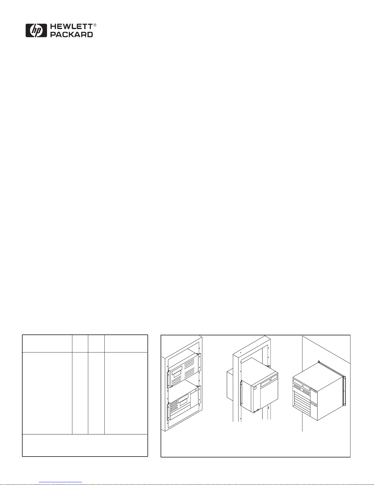
Parts List Installation Options
745
Item
4U Flange
4U Spacer
7U Flange
7U Spacer
Flange screw
Dress screw (with
nylon washer)
Dress screw (with
nylon washer)
Clip nut
Y
our installation may require dif
screws and clip nuts.
Qty.
2
2
4
4
4
748
Part Number
Qty.
A2261–00037
A2261–00039
A4500–000092
A2261–00040
2
6
4
4
0515–1114
0570–1366
0570–1597
0590–0804
ferent dress
Rack Mount
745
and 748
Front
Out
Back
Out
Mast Mount
748 only
ed Model 745 weighs
W
all Mount
748 only
Page 2
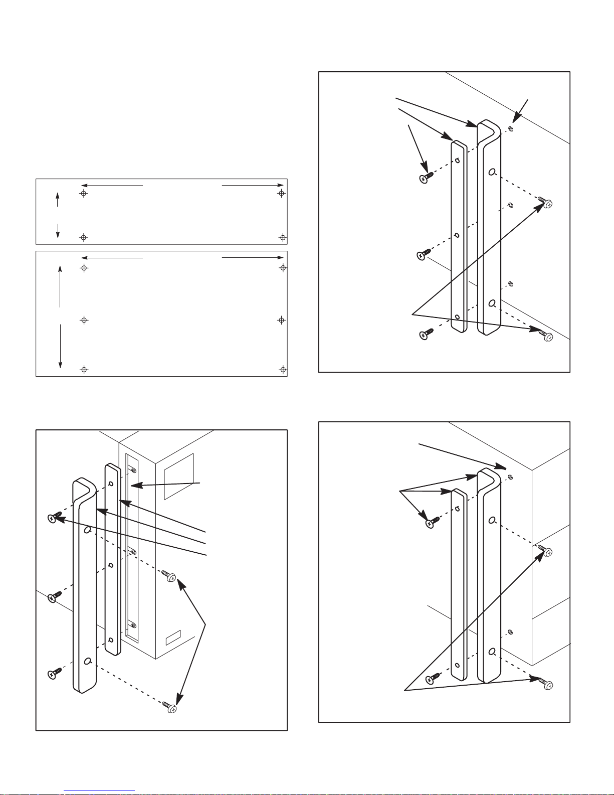
Mast Installation
Model 748 ONLY
Figure 1.
Rack Installation
Figure 2 for Model 748 Front Out.
Figure 3 for Model 745 Front or Back Out,
Model 748 Back Out.
Y
ou may want to remove the feet.
465.5 mm
101.6 mm
235.0 mm
EIA
Standard rack mount for Model 745.
465.5 mm
EIA
Standard rack mount for Model 748.
1. Attach the
flange and
spacer with
flange screws.
CAUTION:
Spacer must be
outside of flange
or screws will
bind internal
modules. Get
someone to
help hold the
system for
installing it in
the mast.
2. Install the
system in
the mast with
dress screws.
Middle holes on
side.
1. Peel off the
trim piece.
2. Attach the
spacer and
flange with
flange screws.
3. Install the
system
in rack with
dress screws.
Figure 1: Mast Mount (748 only)
1. Remove any
existing screws
as needed.
2. Attach the
flange and
spacer with
flange screws.
CAUTION:
Spacer must be
outside of flange
or screws will
bind internal
modules. Get
someone to
help you hold
the system
for installing it
in the rack.
3. Install the
system in
the rack with
dress screws.
Figure 2: 748 Front Out, Rack Mount
2
Figure 3: 745 Front/Back Out, 748 Back Out,
Rack Mount
Page 3

Wall Installation
Model 748 ONLY.
Figures 4, 5, and 6.
Y
ou may want to remove the feet.
465.5 mm
1. Set the workstation upside
down, then pry the three
front cover bottom
catches loose.
235.0 mm
EIA
Standard W
1. Pull off the
power switch button,
then press the
switch arm in
to ON.
all Mount for Model 748.
2. Pry side catches loose
and work front cover
off the workstation.
Figure 4: Removing Front Cover
1. Attach the
spacer and
flange with
flange screws.
CAUTION:
Get two people
to help you hold
the workstation
to wall for
mounting.
2. Press the light pipe
catch to the left,
then pull out the
light pipe.
Figure 5: Removing Switch Button & Light Pipe
3
2. Install the
workstation to
the wall with
dress screws.
Figure 6: Wall Mount
Page 4

Part Number: A2677–90011
Printed in U.S.A.
Edition E0698
 Loading...