

Page 1

User’s Guide
3DUW#1XPEHU=#(69670<3334
-DQXDU\#4<<<1
)RU#6DIHW\#LQIRUPDWLRQ/#:DUUDQWL HV/#DQG#5HJXODWRU\#LQIRUPDWLRQ/
VHH#WKH#SDJHV#EHKL QG#WKH#,QGH[1
‹#&RS\ULJKW#+HZOHWW03DFNDUG#&RPSDQ\#4<<<
$OO#5LJKWV#5HVHUYHG1
+3#(6966$#DQG#(6967$
'RZHU#6XSSOLHV
Page 2

7KH#+3#(6966$#DQG#+3#(6967$#DUH#KLJK#SHUIRUPDQFH#533#ZDWW#VLQJOH0RXWSXW#
GXDO#UDQJH#SURJUDPPDEOH#'&#SRZHU#VXSSOLHV#ZLWK#ERWK#+30,%#DQG#560565#
LQWHUIDFHV1#7KH#FRPELQDWLRQ#RI#EHQFK0WRS#DQG#V\VWHP#IHDWXUHV#LQ#WKHVH#SRZHU#
VXSSOLHV#SURYLGHV#YHUVDWLOH#VROXWLRQV#IRU#\RXU#GHVLJQ#DQG#WHVW#UHTXLUHPHQWV1
&RQYHQLHQW#EHQFK0WRS#IHDWXUHV
‡6LQJOH0RXWSXW#GXDO#UDQJH
‡(DV\0WR0XVH#NQRE#FRQWURO#VHWWLQJV
‡+LJKO\#YLVLEOH#YDFXXP0IOXRUHVFHQW#GLVSOD\#PHWHUV
‡+LJK#DFFXUDF\#DQG#KLJK#UHVROXWLRQ
‡5HPRWH#YROWDJH#VHQVLQJ
‡ 2YHUYROWDJH#DQG#RYHUFXUUHQW#SURWHFWLRQ
‡ 2XWSXW#RQ2RII
‡ ([FHOOHQW#ORDG#DQG#OLQH#UHJXODWLRQ#DQG#ORZ#ULSSOH#DQG#QRLVH
‡ 2SHUDWLQJ#VWDWHV#VWRUDJH
‡ 3RUWDEOH/#UXJJHGL]HG#FDVH#ZLWK#QRQ0VNLG#IHHW
‡)URQW#DQG#5HDU#RXWSXW#WHUPLQDOV
‡ 5HWULHYLQJ26FUROOLQJ#HUURU#PHVVDJHV#RQ#WKH#GLVSOD\
)OH[LEOH#V\VWHP#IHDWXUHV
‡+30,%#+,(((07;;,#DQG#560565#LQWHUIDFHV#DUH#VWDQGDUG
‡6&3,#+6WDQGDUG#&RPPDQGV#IRU#3URJUDPPDEOH#,QVWUXPHQWV,#FRPSDWLELOLW\
‡,22#VHWXS#HDVLO\#GRQH#IURP#IURQW0SDQHO
‡ 6RIWZDUH#FDOLEUDWLRQ/#QR#LQWHUQDO#DGMXVWPHQWV#UHTXLUHG
+3#(6966$#DQG#(6967$
'RZHU#6XSSOLHV
Page 3
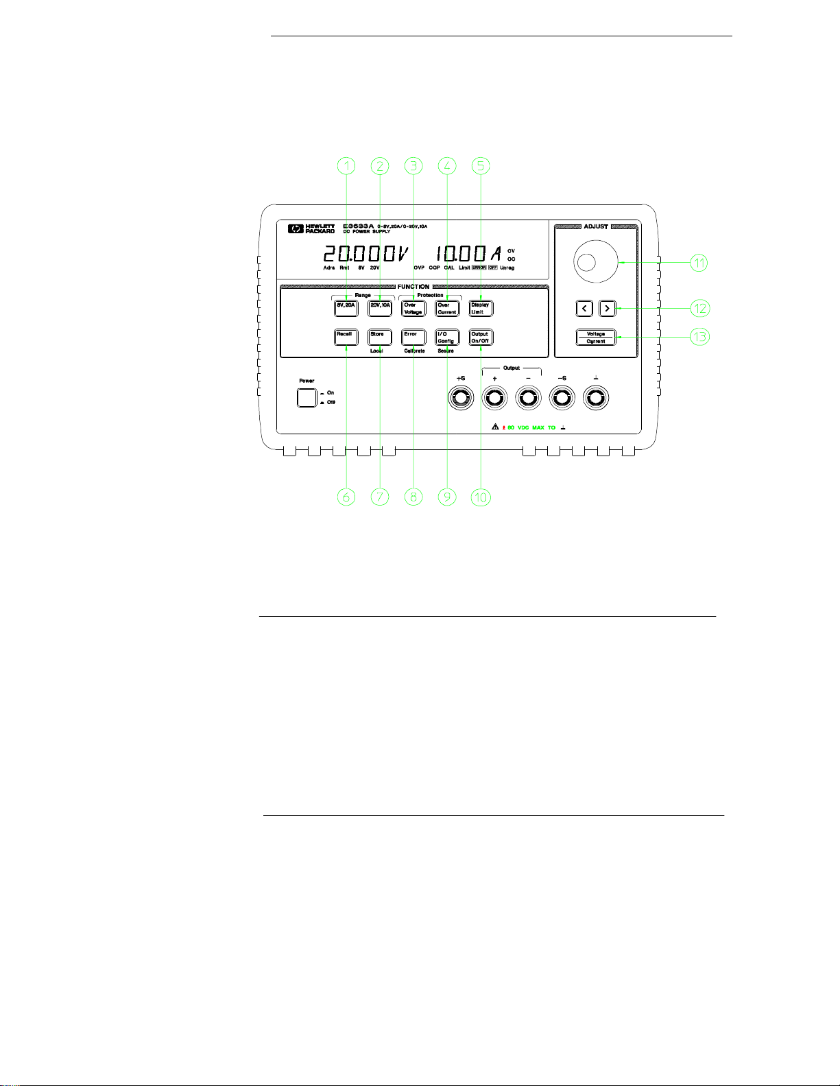
The Front Panel at a Glance
1 8V/20A range selecti on key (E3633A)
25V/7A range selection key (E3634A)
2 20V/10A range selection k ey (E3633A)
50V/4A range selection key (E3634A)
3 Overvoltage protecti on key
4 Overcurrent protection key
5 Display limit key
6 Recall operating state key
2
7 Store operating state/Local key
8 Error/Calibrate key
9 I/O Configuration/Secure key
10 Output On/Off key
11 Control knob
12 Resolution selection keys
13 Voltage/current adjust selection key
Page 4

1 8V/20A* or 25V/7A** range selection key Selects the 8V/20A or 25V/7A
range and allows the full rated output to 8V/20A or 25V/7A.
2 20V/10A* or 50V/4A** range selection key Selects the 20V/10A or
50V/4A range and allows the full rated output to 20V/10A or 50V/4A.
3 Overvoltage protection key Enables or disables the overvoltage protection
function, sets trip voltage level, and clears the overvoltage condition.
4 Overcurrent protection key Enables or disables the overcurrent protection
function, sets trip current level, and clears the overcurrent condition.
5 Display limit key Shows voltage and current limit values on the display and
allows knob adjustment for setting limit values.
6 Recall operating state key Recalls a previously stored operating state from
location ‘‘1’’, ‘‘2’’, or ‘‘3’’.
7 Store operating state / Local key
1
Stores an operating state in location ‘‘1’’,
‘‘2’’, or ‘‘3’’ / or returns the power supply to local mode from remote interface
mode.
8 Error / Calibrate key
2
Displays error codes generated during operation, selftest and calibration / or enables calibration mode (the power supply must be
unsecured before performing calibration). See
Service G uide
for more details
on calibration.
3
9 I/O Configuration / Secure key
Configures the power supply for remote
interfaces / or secure or unsecure the power supply for calibration. See
Serv ice Guide
for more details on how to secure or unsecure the power supply.
10 Output On/O ff key En ables or disables the power supply output . This key
toggles between on and off.
11 C ontro l knob Increases or decreases the value of the blinking digit by turning
clockwise or counter clockwise.
12 Resolution selection keys Move the blinking digit to the right or left.
13 Voltage/current adjust selection key Selects the knob control function for
voltage or current adjustment.
1
7KH#NH\#FDQ#EH#XVHG#DV#WKH#©©
Local
ªª#NH\#ZKHQ#WKH#SRZHU#VXSSO\#LV#LQ#WKH#UHPRWH#
LQWHUIDFH#PRGH1
2
<RX#FDQ#HQDEOH#WKH#©©FDOLEUDWLRQ#PRGHªª#E\#KROGLQJ#GRZQ#WKLV#NH\#ZKHQ#\RX#
WXUQ#RQ#WKH#SRZHU#VXSSO\1
3
<RX#FDQ#XVH#LW#DV#WKH#©©6HFXUHªª#RU#©©8QVHFXUHªª#NH\#ZKHQ#WKH#SRZHU#VXSSO\#LV#
LQ#WKH#FDOLEUDWLRQ#PRGH1
*For HP E3633A Model **For HP E3634A Model
3
Page 5
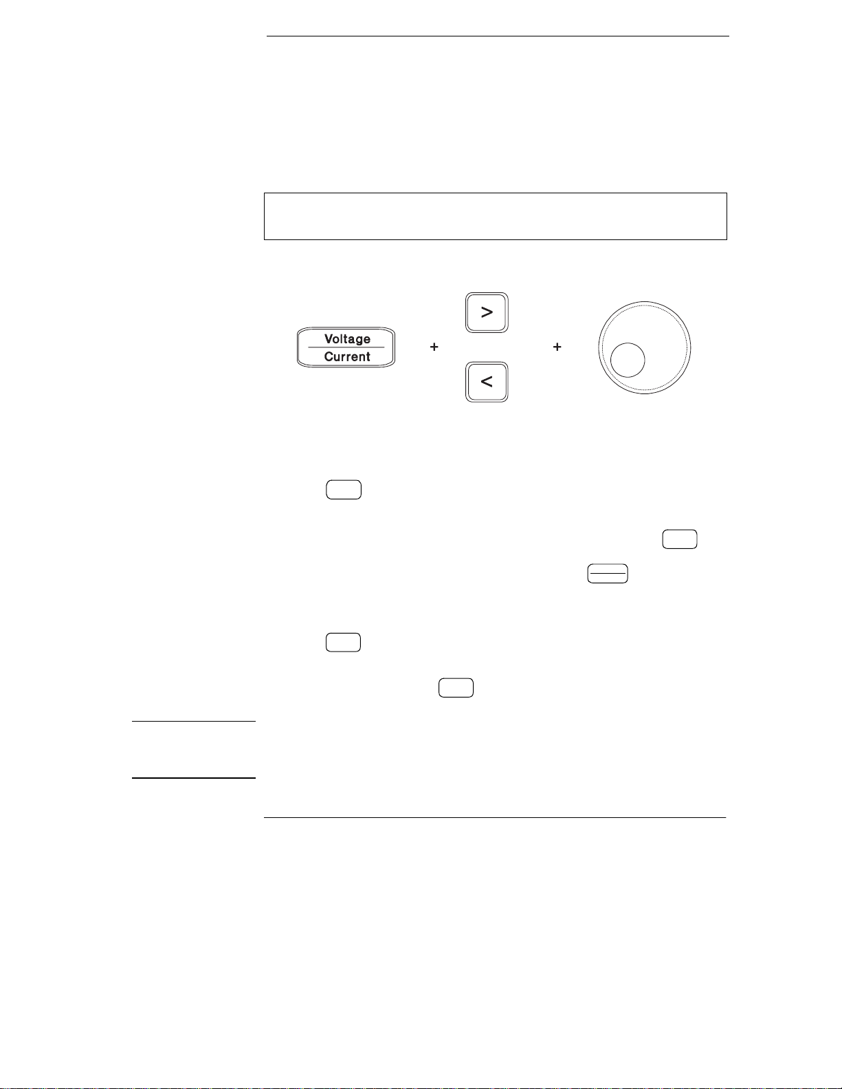
Front-Panel Voltage a nd Cu rrent Limit Settings
Output
On/Off
Y ou can set the voltage and current limit values from the front panel using the
following method.
Use the voltage/current adjust selection key, the resolution selection keys,
and the control knob to change the voltage and current limit values.
1 Select the desired range using the range selection keys after turning on the
power supply.
2 Press the #key to show the limit values on the display.
3 Move the blinking digit to the appropriate position using the resolution
selection keys and change the blinking digit value to the desired voltage limit
by turning the control knob. If the display limit times out, press the key
again.
4 Set the knob to current control mode by pressing the key.
5 Move the blinking digit to the appropriate position using the resolution
selection keys and change the blinking digit value to the desired current limit
by turning the control knob.
6 Press the #key to enable the output. After about 5 seconds, the display
will go to output monitoring mode automatically to display the voltage and
current at the output or the display will go to output monitoring mode
immediately by pressing the #key again.
Display
Limit
Output
On/Off
Voltage
Current
Display
Limit
Note All front panel keys and controls ca n be dis abled with remote interface commands.
The HP E3633A and HP E3634A must be in "Local" mode for the front panel keys
and controls to function.
4
Page 6
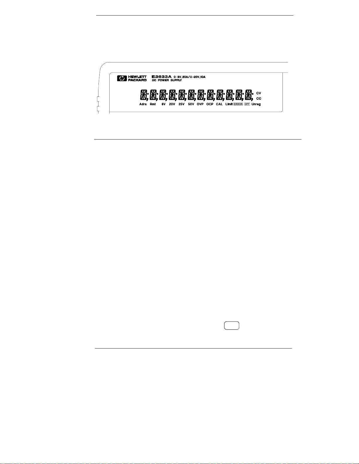
Display Annunciators
Adrs Power supply is addressed to listen or talk over a remote interface.
Rmt Power supply is in remote interface mode.
8V Shows the 8V/20A range is selected. (HP E3633A model)
20V Shows the 20V/10A range is selected. (HP E3633A mod el)
25V Shows the 25V/7A range is selected. (HP E3634A model)
50V Shows the 50V/4A range is selected. (HP E3634A model)
OVP The overvoltage protection function is enabled when the
annunciator turns on or the overvoltage protection circuit has
caused the power supply to shutdown when the annunciator blinks.
OCP The overcurrent protection function is enabled when the
annunciator turns on or the overcurrent protection circuit has
caused the power supply to shutdown when the annunciator blinks.
CAL The power supply is in calibration mode.
Limit The display shows the limit values of voltage and current.
ERROR Hardware or remote interface command errors are detected and
the error bit has not been cleared.
OFF The output of the power supply is disabled (See page 52 for more
information).
Unreg The output of the power supply is unregulated (output is neither CV
nor CC).
CV The power supply is in constant voltage mode.
CC The power supply is in constant current mode.
To review the display annunciators, hold down key as you turn on
Display
Limit
the power supply.
5
Page 7
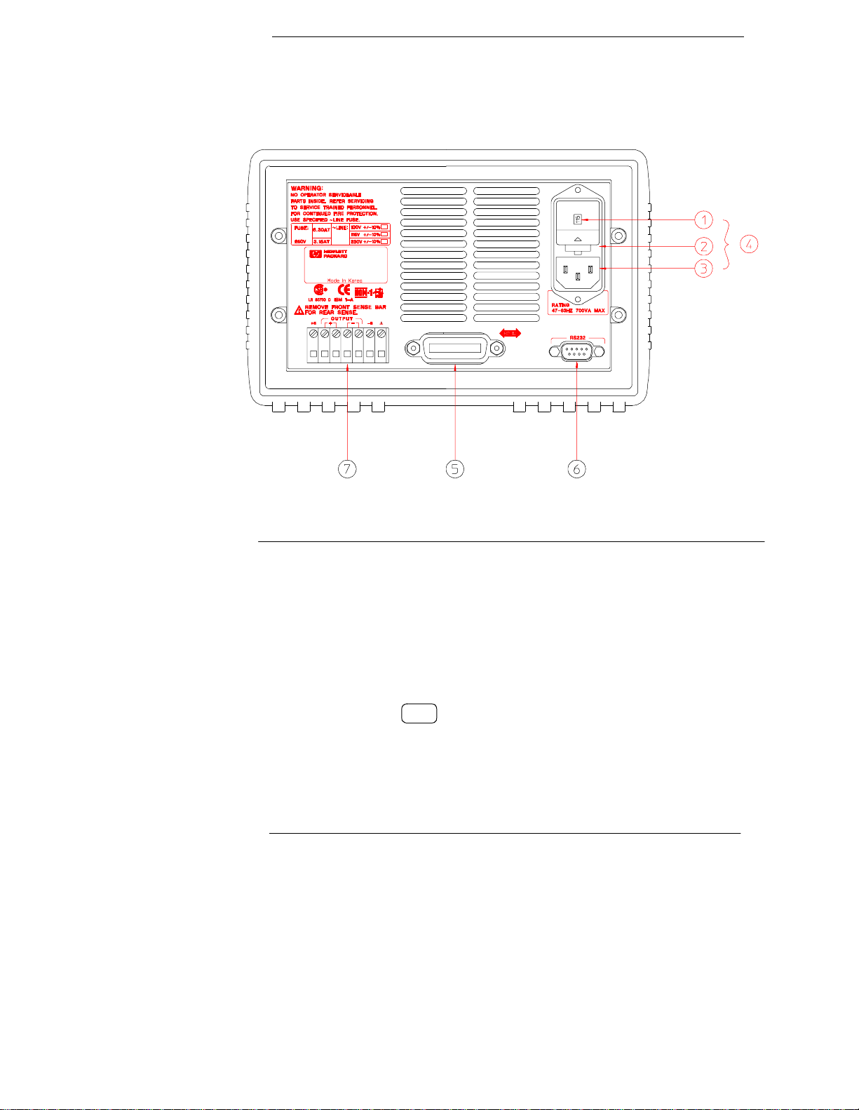
The Rear Panel at a Glance
1 Power-line voltage setting
2 Power-line fuse-holder assembly
3 AC inlet
5 HP-IB (IEEE-488) interface connector
6 RS-232 interface connector
7 Rear output terminals
4 Power-line module
Use the front-panel key to:
I/O
Config
• Select the HP-IB or RS-232 interface (see chapter 3).
• Set the HP-IB bus address (see chapter 3).
• Set the RS-232 baud rate and parity (see chapter 3).
6
Page 8

In This Book
*HQHUDO#,QIRUPDWLRQ####&KDSWHU#4#FRQWDLQV#D#JHQHUDO#GHVFULSWLRQ#RI#\RXU#
SRZHU#VXSSO\1#7KLV#FKDSWHU#DOVR##SURYLGHV#LQVWUXFWLRQV#IRU#FKHFNLQJ#\RXU#SRZHU#
VXSSO\/#FRQQHFWLQJ#WR#DF#SRZHU/#DQG#VHOHFWLQJ#SRZHU0OLQH#YROWDJH1
,QLWLDO#2SHUDWLRQ####&KDSWHU#5#HQVXUHV#WKDW#WKH#SRZHU#VXSSO\#GHYHORSV#LWV#UDWHG#
RXWSXWV#DQG#SURSHUO\#UHVSRQGV#WR#RSHUDWLRQ#IURP#WKH#IURQW#SDQHO1
)URQW03DQHO#2SHUDWLRQ####&KDSWHU#6#GHVFULEHV#LQ#GHWDLO#WKH#XVH#RI#IURQW0SDQHO#
NH\V#DQG#KRZ#WKH\#DUH#XVHG#WR#RSHUDWH#WKH#SRZHU#VXSSO\#IURP#WKH#IURQW#SDQHO1#
7KLV#FKDSWHU#DOVR#VKRZV#KRZ#WR#FRQILJXUH#WKH#SRZHU#VXSSO\#IRU#WKH#UHPRWH#
LQWHUIDFH#DQG#JLYHV#D#EULHI#LQWURGXFWLRQ#WR#WKH#FDOLEUDWLRQ#IHDWXUHV1
5HPRWH#,QWHUIDFH#5HIHUHQFH###&KDSWHU#7#FRQWDLQV#UHIHUHQFH#LQIRUPDWLRQ#WR#
KHOS#\RX#SURJUDP#WKH#SRZHU#VXSSO\#RYHU#WKH#UHPRWH#LQWHUIDFH1#7KLV#FKDSWHU#
DOVR#H[SODLQV#KRZ#WR#SURJUDP#IRU#VWDWXV#UHSRUWLQJ1
(UURU#0HVVDJHV###&KDSWHU#8#OLVWV#WKH#HUURU#PHVVDJHV#WKDW#PD\#DSSHDU#DV#\RX#
DUH#ZRUNLQJ#ZLWK#WKH#SRZHU#VXSSO\1#(DFK#OLVWLQJ#FRQWDLQV#LQIRUPDWLRQ#WR#KHOS#
\RX#GLDJQRVH#DQG#VROYH#WKH#SUREOHP1
$SSOLFDWLRQ#3URJUDPV####&KDSWHU#9#FRQWDLQV#VRPH#UHPRWH#LQWHUIDFH#
DSSOLFDWLRQV#WR#KHOS#\RX#GHYHORS#SURJUDPV#IRU#\RXU#DSSOLFDWLRQ1
7XWRULDO#####&KDSWHU#:#GHVFULEHV#EDVLF#RSHUDWLRQ#RI#OLQHDU#SRZHU#VXSSOLHV#DQG#
JLYHV#VSHFLILF#GHWDLOV#RQ#WKH#RSHUDWLRQ#DQG#XVH#RI#WKH#+3#(6966$#DQG#+3#
(6967$#SRZHU#VXSSOLHV1
6SHFLILFDWLRQV#####&KDSWHU#;#OLVWV#WKH#SRZHU#VXSSO\ªV#VSHFLILFDWLRQV1
If you have questions relating to the operation of the power supply, call
1-800-452-4844 in the United States, or contact your neares t Hewlett- Pac kard
Sales Office.
If your HP E3633A or HP E3634A fails within three years of purchase, HP will
repair or replace it free of char ge. Call 1-800-258-51 65 ("Express Exchange")
in the United States , or contact your neares t Hewlett- Packard Sales Offic e.
7
Page 9

8
Page 10

Contents
&KDSWHU#4##*HQHUDO#,QIRUPDWLRQ
6DIHW\#&RQVLGHUDWLRQV0#0#0#0#0#0#0#0#0#0#0#0#0#0#0#0#0#0#0#0#0#0#0#0#0#0#0#0#0#0#0#0#0#0 #47
6DIHW\#DQG#(0HTXLUHPHQWV 0#0#0#0#0#0#0#0#0#0#0#0#0#0#0#0#0#0#0#0#0#0#0#0 #47
2SWLRQV#DQG#$FFHVVRULHV #0#0#0#0#0#0#0#0#0#0#0#0#0#0#0#0#0#0#0#0#0#0#0#0#0#0#0#0#0#0#0 #48
2SWLRQV0#0#0#0#0#0#0#0#0#0#0#0#0#0#0#0#0#0#0#0#0#0#0#0#0#0#0#0#0#0#0#0#0#0#0#0#0#0#0#0#0#0#0 #48
$FFHVVRULHV#0#0#0#0#0#0#0#0#0#0#0#0#0#0#0#0#0#0#0#0#0#0#0#0#0#0#0#0#0#0#0#0#0#0#0#0#0#0#0 #48
'HVFULSWLRQ#0#0#0#0#0#0#0#0#0#0#0#0#0#0#0#0#0#0#0#0#0#0#0#0#0#0#0#0#0#0#0#0#0#0#0#0#0#0#0#0#0#0 #49
,QVWDOODWLRQ #0#0#0#0#0#0#0#0#0#0#0#0#0#0#0#0#0#0#0#0#0#0#0#0#0#0#0#0#0#0#0#0#0#0#0#0#0#0#0#0#0#0 #4<
,QLWLDO#,QVSHFWLRQ#0#0#0#0#0#0#0#0#0#0#0#0#0#0#0#0#0#0#0#0#0#0#0#0#0#0#0#0#0#0#0#0#0#0#0 #4<
&RROLQJ#DQG#/RFDWLRQ #0#0#0#0#0#0#0#0#0#0#0#0#0#0#0#0#0#0#0#0#0#0#0#0#0#0#0#0#0#0#0 #4<
,QSXW#3RZHU#5HTXLUHPHQWV0#0#0#0#0#0#0#0#0#0#0#0#0#0#0#0#0#0#0#0#0#0#0#0#0#0#0#0#0#0 #55
3RZHU0/LQH#&RUG#0#0#0#0#0#0#0#0#0#0#0#0#0#0#0#0#0#0#0#0#0#0#0#0#0#0#0#0#0#0#0#0#0#0#0 #55
3RZHU0/LQH#9ROWDJH#6HOHFWLRQ0#0#0#0#0#0#0#0#0#0#0#0#0#0#0#0#0#0#0#0#0#0#0#0#0 #55
&KDSWHU#5##,QLWLDO#2SHUDWLRQ
3UHOLPLQDU\#&KHFNRXW0#0#0#0#0#0#0#0#0#0#0#0#0#0#0#0#0#0#0#0#0#0#0#0#0#0#0#0#0#0#0#0#0#0 #5:
3RZHU02Q#&KHFNRXW#0#0#0#0#0#0#0#0#0#0#0#0#0#0#0#0#0#0#0#0#0#0#0#0#0#0#0#0#0#0#0#0#0#0#0 #5;
2XWSXW#&KHFNRXW0#0#0#0#0#0#0#0#0#0#0#0#0#0#0#0#0#0#0#0#0#0#0#0#0#0#0#0#0#0#0#0#0#0#0#0#0#0 #5<
9ROWDJH#2XWSXW#&KHFNRXW#0#0#0#0#0#0#0#0#0#0#0#0#0#0#0#0#0#0#0#0#0#0#0#0#0#0#0#0 #5<
&XUUHQW#2XWSXW#&KHFNRXW 0#0#0#0#0#0#0#0#0#0#0#0#0#0#0#0#0#0#0#0#0#0#0#0#0#0#0#0 #63
Contents
&KDSWHU#6##)URQW03DQHO#2SHUDWLRQ
)URQW03DQHO#2SHUDWLRQ#2YHUYLHZ 0#0#0#0#0#0#0#0#0#0#0#0#0#0#0#0#0#0#0#0#0#0#0#0#0 #68
&RQVWDQW#9ROWDJH#2SHUDWLRQ 0#0#0#0#0#0#0#0#0#0#0#0#0#0#0#0#0#0#0#0#0#0#0#0#0#0#0#0#0 #69
&RQVWDQW#&XUUHQW#2SHUDWLRQ0#0#0#0#0#0#0#0#0#0#0#0#0#0#0#0#0#0#0#0#0#0#0#0#0#0#0#0#0 #6;
6WRULQJ#DQG#5HFDOOLQJ#2SHUDWLQJ#6WDWHV 0#0#0#0#0#0#0#0#0#0#0#0#0#0#0#0#0#0#0#0 #73
3URJUDPPLQJ#2YHUYROWDJH#3URWHFWLRQ 0#0#0#0#0#0#0#0#0#0#0#0#0#0#0#0#0#0#0#0#0 #75
6HWWLQJ#WKH#293#/HYHO#DQG#(QDEOH#WKH#293#&LUFXLW 0#0#0#0#0#0#0#0 #75
&KHFNLQJ#293#2SHUDWLRQ #0#0#0#0#0#0#0#0#0#0#0#0#0#0#0#0#0#0#0#0#0#0#0#0#0#0#0#0 #76
&OHDULQJ#WKH#2YHUYROWDJH#&RQGLWLRQ 0#0#0#0#0#0#0#0#0#0#0#0#0#0#0#0#0#0#0#0 #76
3URJUDPPLQJ#2YHUFXUUHQW#3URWHFWLRQ 0#0#0#0#0#0#0#0#0#0#0#0#0#0#0#0#0#0#0#0#0 #79
6HWWLQJ#WKH#2&3#/HYHO#DQG#(QDEOH#WKH#2&3#&LUFXLW0#0#0#0#0#0#0#0 #79
&KHFNLQJ#2&3#2SHUDWLRQ #0#0#0#0#0#0#0#0#0#0#0#0#0#0#0#0#0#0#0#0#0#0#0#0#0#0#0#0 #7:
&OHDULQJ#WKH#2YHUFXUUHQW#&RQGLWLRQ 0#0#0#0#0#0#0#0#0#0#0#0#0#0#0#0#0#0#0#0 #7:
5HPRWH#9ROWDJH#6HQVLQJ#DW#WKH#)URQW#DQG#5HDU#7HUPLQDOV 0#0#0#0#0 #7<
&9#5HJXODWLRQ#0#0#0#0#0#0#0#0#0#0#0#0#0#0#0#0#0#0#0#0#0#0#0#0#0#0#0#0#0#0#0#0#0#0#0#0#0 #7<
2XWSXW#5DWLQJ #0#0#0#0#0#0#0#0#0#0#0#0#0#0#0#0#0#0#0#0#0#0#0#0#0#0#0#0#0#0#0#0#0#0#0#0#0 #7<
2XWSXW#1RLVH#0#0#0#0#0#0#0#0#0#0#0#0#0#0#0#0#0#0#0#0#0#0#0#0#0#0#0#0#0#0#0#0#0#0#0#0#0#0 #7<
6WDELOLW\ #0#0#0#0#0#0#0#0#0#0#0#0#0#0#0#0#0#0#0#0#0#0#0#0#0#0#0#0#0#0#0#0#0#0#0#0#0#0#0#0#0#0 #83
5HPRWH#9ROWDJH#6HQVLQJ#&RQQHFWLRQV #0#0#0#0#0#0#0#0#0#0#0#0#0#0#0#0#0#0 #83
5HPRWH#9ROWDJH#6HQVLQJ#DW#WKH#5HDU#3DQHO #0#0#0#0#0#0#0#0#0#0#0#0#0#0 #84
9
Page 11

Contents
'LVDEOLQJ#WKH#2XWSXW 0#0#0#0#0#0#0#0#0#0#0#0#0#0#0#0#0#0#0#0#0#0#0#0#0#0#0#0#0#0#0#0#0#0#0#85
'LVDEOLQJ#WKH#2XWSXW#8VLQJ#DQ#([WHUQDO#5HOD\0#0#0#0#0#0#0#0#0#0#0#0#0#0#0#86
.QRE#/RFNLQJ0#0#0#0#0#0#0#0#0#0#0#0#0#0#0#0#0#0#0#0#0#0#0#0#0#0#0#0#0#0#0#0#0#0#0#0#0#0#0#0#0#86
6\VWHP05HODWHG#2SHUDWLRQV0#0#0#0#0#0#0#0#0#0#0#0#0#0#0#0#0#0#0#0#0#0#0#0#0#0#0#0#0#0#87
6HOI07HVW#0#0#0#0#0#0#0#0#0#0#0#0#0#0#0#0#0#0#0#0#0#0#0#0#0#0#0#0#0#0#0#0#0#0#0#0#0#0#0#0#0#0#87
(UURU#&RQGLWLRQV #0#0#0#0#0#0#0#0#0#0#0#0#0#0#0#0#0#0#0#0#0#0#0#0#0#0#0#0#0#0#0#0#0#0#0#88
'LVSOD\#&RQWURO #0#0#0#0#0#0#0#0#0#0#0#0#0#0#0#0#0#0#0#0#0#0#0#0#0#0#0#0#0#0#0#0#0#0#0#0#89
)LUPZDUH#5HYLVLRQ#4XHU\#0#0#0#0#0#0#0#0#0#0#0#0#0#0#0#0#0#0#0#0#0#0#0#0#0#0#0#0#8:
6&3,#/DQJXDJH#9HUVLRQ#0#0#0#0#0#0#0#0#0#0#0#0#0#0#0#0#0#0#0#0#0#0#0#0#0#0#0#0#0#0#8:
5HPRWH#,QWHUIDFH#&RQILJXUDWLRQ 0#0#0#0#0#0#0#0#0#0#0#0#0#0#0#0#0#0#0#0#0#0#0#0#0#0#8;
5HPRWH#,QWHUIDFH#6HOHFWLRQ 0#0#0#0#0#0#0#0#0#0#0#0#0#0#0#0#0#0#0#0#0#0#0#0#0#0#0#8;
+30,%#$GGUHVV #0#0#0#0#0#0#0#0#0#0#0#0#0#0#0#0#0#0#0#0#0#0#0#0#0#0#0#0#0#0#0#0#0#0#0#0#0#8<
%DXG#5DWH#6HOHFWLRQ#+560565,#0#0#0#0#0#0#0#0#0#0#0#0#0#0#0#0#0#0#0#0#0#0#0#0#0#8<
3DULW\#6HOHFWLRQ#+560565,0#0#0#0#0#0#0#0#0#0#0#0#0#0#0#0#0#0#0#0#0#0#0#0#0#0#0#0#0#8<
7R#6HW#WKH#+30,%#$GGUHVV #0#0#0#0#0#0#0#0#0#0#0#0#0#0#0#0#0#0#0#0#0#0#0#0#0#0#0#0#93
7R#6HW#WKH#%DXG#5DWH#DQG#3DULW\#+560565, #0#0#0#0#0#0#0#0#0#0#0#0#0#0#0#94
+30,%#,QWHUIDFH#&RQILJXUDWLRQ #0#0#0#0#0#0#0#0#0#0#0#0#0#0#0#0#0#0#0#0#0#0#0#0#0#0#0#96
560565#,QWHUIDFH#&RQILJXUDWLRQ0#0#0#0#0#0#0#0#0#0#0#0#0#0#0#0#0#0#0#0#0#0#0#0#0#0#0#97
560565#&RQILJXUDWLRQ#2YHUYLHZ #0#0#0#0#0#0#0#0#0#0#0#0#0#0#0#0#0#0#0#0#0#0#0#97
560565#'DWD#)UDPH#)RUPDW 0#0#0#0#0#0#0#0#0#0#0#0#0#0#0#0#0#0#0#0#0#0#0#0#0#0#0#97
&RQQHFWLRQ#WR#D#&RPSXWHU#RU#7HUPLQDO #0#0#0#0#0#0#0#0#0#0#0#0#0#0#0#0#0#98
Contents
'75#2#'65#+DQGVKDNH#3URWRFRO#0#0#0#0#0#0#0#0#0#0#0#0#0#0#0#0#0#0#0#0#0#0#0#99
560565#7URXEOHVKRRWLQJ0#0#0#0#0#0#0#0#0#0#0#0#0#0#0#0#0#0#0#0#0#0#0#0#0#0#0#0#0#0#9:
&DOLEUDWLRQ#2YHUYLHZ #0#0#0#0#0#0#0#0#0#0#0#0#0#0#0#0#0#0#0#0#0#0#0#0#0#0#0#0#0#0#0#0#0#0#9;
&DOLEUDWLRQ#6HFXULW\ 0#0#0#0#0#0#0#0#0#0#0#0#0#0#0#0#0#0#0#0#0#0#0#0#0#0#0#0#0#0#0#0#0#9;
&DOLEUDWLRQ#&RXQW0#0#0#0#0#0#0#0#0#0#0#0#0#0#0#0#0#0#0#0#0#0#0#0#0#0#0#0#0#0#0#0#0#0#0#:5
&DOLEUDWLRQ#0HVVDJH0#0#0#0#0#0#0#0#0#0#0#0#0#0#0#0#0#0#0#0#0#0#0#0#0#0#0#0#0#0#0#0#0#:5
10
&KDSWHU#7##5HPRWH#,QWHUIDFH#5HIHUHQFH
6&3,#&RPPDQG#6XPPDU\0#0#0#0#0#0#0#0#0#0#0#0#0#0#0#0#0#0#0#0#0#0#0#0#0#0#0#0#0#0#0#:8
6LPSOLILHG#3URJUDPPLQJ#2YHUYLHZ0#0#0#0#0#0#0#0#0#0#0#0#0#0#0#0#0#0#0#0#0#0#0#0#;3
8VLQJ#WKH#
8VLQJ#WKH#/RZ0/HYHO#&RPPDQGV 0#0#0#0#0#0#0#0#0#0#0#0#0#0#0#0#0#0#0#0#0#0#0#;3
5HDGLQJ#D#4XHU\#5HVSRQVH #0#0#0#0#0#0#0#0#0#0#0#0#0#0#0#0#0#0#0#0#0#0#0#0#0#0#0#;4
6HOHFWLQJ#D#7ULJJHU#6RXUFH0#0#0#0#0#0#0#0#0#0#0#0#0#0#0#0#0#0#0#0#0#0#0#0#0#0#0#0#;4
3RZHU#6XSSO\#3URJUDPPLQJ#5DQJHV0#0#0#0#0#0#0#0#0#0#0#0#0#0#0#0#0#0#0#0#;5
8VLQJ#WKH#
2XWSXW#6HWWLQJ#DQG#2SHUDWLRQ#&RPPDQGV 0#0#0#0#0#0#0#0#0#0#0#0#0#0#0#0#0#0#;7
7ULJJHULQJ#&RPPDQGV0#0#0#0#0#0#0#0#0#0#0#0#0#0#0#0#0#0#0#0#0#0#0#0#0#0#0#0#0#0#0#0#0#0#<4
7ULJJHU#6RXUFH#&KRLFHV#0#0#0#0#0#0#0#0#0#0#0#0#0#0#0#0#0#0#0#0#0#0#0#0#0#0#0#0#0#0#<4
7ULJJHULQJ#&RPPDQGV#0#0#0#0#0#0#0#0#0#0#0#0#0#0#0#0#0#0#0#0#0#0#0#0#0#0#0#0#0#0#0#<6
6\VWHP05HODWHG#&RPPDQGV #0#0#0#0#0#0#0#0#0#0#0#0#0#0#0#0#0#0#0#0#0#0#0#0#0#0#0#0#0#<7
APPLy
APPLy
#&RPPDQG 0#0#0#0#0#0#0#0#0#0#0#0#0#0#0#0#0#0#0#0#0#0#0#0#0#0#;3
#&RPPDQG0#0#0#0#0#0#0#0#0#0#0#0#0#0#0#0#0#0#0#0#0#0#0#0#0#0#0#0#0#;6
Page 12

Contents
&DOLEUDWLRQ#&RPPDQGV 0#0#0#0#0#0#0#0#0#0#0#0#0#0#0#0#0#0#0#0#0#0#0#0#0#0#0#0#0#0#0#0#0 #<;
560565#,QWHUIDFH#&RPPDQGV #0#0#0#0#0#0#0#0#0#0#0#0#0#0#0#0#0#0#0#0#0#0#0#0#0#0#0 #434
7KH#6&3,#6WDWXV#5HJLVWHUV #0#0#0#0#0#0#0#0#0#0#0#0#0#0#0#0#0#0#0#0#0#0#0#0#0#0#0#0#0 #435
:KDW#LV#DQ#(YHQW#5HJLVWHU"#0#0#0#0#0#0#0#0#0#0#0#0#0#0#0#0#0#0#0#0#0#0#0#0#0#0 #435
:KDW#LV#DQ#(QDEOH#5HJLVWHU"#0#0#0#0#0#0#0#0#0#0#0#0#0#0#0#0#0#0#0#0#0#0#0#0#0 #435
6&3,#6WDWXV#6\VWHP 0#0#0#0#0#0#0#0#0#0#0#0#0#0#0#0#0#0#0#0#0#0#0#0#0#0#0#0#0#0#0#0 #436
7KH#4XHVWLRQDEOH#6WDWXV#5HJLVWHU0#0#0#0#0#0#0#0#0#0#0#0#0#0#0#0#0#0#0#0#0 #437
7KH#6WDQGDUG#(YHQW#5HJLVWHU #0#0#0#0#0#0#0#0#0#0#0#0#0#0#0#0#0#0#0#0#0#0#0#0 #438
7KH#6WDWXV#%\WH#5HJLVWHU0#0#0#0#0#0#0#0#0#0#0#0#0#0#0#0#0#0#0#0#0#0#0#0#0#0#0#0 #439
8VLQJ#6HUYLFH#5HTXHVW#+654,#DQG#6HULDO#32// #0#0#0#0#0#0#0#0#0#0 #43:
8VLQJ#-67%"#WR#5HDG#WKH#6WDWXV#%\WH 0#0#0#0#0#0#0#0#0#0#0#0#0#0#0#0#0#0 #43;
8VLQJ#WKH#0HVVDJH#$YDLODEOH#%LW#+0$9,0#0#0#0#0#0#0#0#0#0#0#0#0#0#0#0 #43;
7R#,QWHUUXSW#<RXU#%XV#&RQWUROOHU#8VLQJ#654 #0#0#0#0#0#0#0#0#0#0#0 #43;
7R#'HWHUPLQH#:KHQ#D#&RPPDQG#6HTXHQFH#LV#&RPSOHWHG #0 #43<
8VLQJ#-23&#WR#6LJQDO#:KHQ#'DWD#LV#LQ#WKH#2XWSXW#%XIIHU#0#0 #43<
6WDWXV#5HSRUWLQJ#&RPPDQGV#0#0#0#0#0#0#0#0#0#0#0#0#0#0#0#0#0#0#0#0#0#0#0#0#0#0#0 #443
$Q#,QWURGXFWLRQ#WR#WKH#6&3,#/DQJXDJH #0#0#0#0#0#0#0#0#0#0#0#0#0#0#0#0#0#0#0 #446
&RPPDQG#)RUPDW#8VHG#LQ#7KLV#0DQXDO0#0#0#0#0#0#0#0#0#0#0#0#0#0#0#0 #447
&RPPDQG#6HSDUDWRUV #0#0#0#0#0#0#0#0#0#0#0#0#0#0#0#0#0#0#0#0#0#0#0#0#0#0#0#0#0#0 #448
8VLQJ#WKH#0,1#DQG#0$;#3DUDPHWHUV#0#0#0#0#0#0#0#0#0#0#0#0#0#0#0#0#0#0 #448
4XHU\LQJ#3DUDPHWHU#6HWWLQJV #0#0#0#0#0#0#0#0#0#0#0#0#0#0#0#0#0#0#0#0#0#0#0#0 #449
6&3,#&RPPDQG#7HUPLQDWRUV #0#0#0#0#0#0#0#0#0#0#0#0#0#0#0#0#0#0#0#0#0#0#0#0 #449
,(((07;;15#&RPPRQ#&RPPDQGV#0#0#0#0#0#0#0#0#0#0#0#0#0#0#0#0#0#0#0#0#0 #449
6&3,#3DUDPHWHU#7\SHV #0#0#0#0#0#0#0#0#0#0#0#0#0#0#0#0#0#0#0#0#0#0#0#0#0#0#0#0#0 #44:
+DOWLQJ#DQ#2XWSXW#LQ#3URJUHVV #0#0#0#0#0#0#0#0#0#0#0#0#0#0#0#0#0#0#0#0#0#0#0#0#0#0 #44;
6&3,#&RQIRUPDQFH#,QIRUPDWLRQ0#0#0#0#0#0#0#0#0#0#0#0#0#0#0#0#0#0#0#0#0#0#0#0#0 #44<
,(((07;;#&RQIRUPDQFH#,QIRUPDWLRQ 0#0#0#0#0#0#0#0#0#0#0#0#0#0#0#0#0#0#0#0#0 #455
Contents
&KDSWHU#8##(UURU#0HVVDJHV
([HFXWLRQ#(UURUV #0#0#0#0#0#0#0#0#0#0#0#0#0#0#0#0#0#0#0#0#0#0#0#0#0#0#0#0#0#0#0#0#0#0#0#0 #458
6HOI07HVW#(UURUV0#0#0#0#0#0#0#0#0#0#0#0#0#0#0#0#0#0#0#0#0#0#0#0#0#0#0#0#0#0#0#0#0#0#0#0#0#0 #463
&DOLEUDWLRQ#(UURUV 0#0#0#0#0#0#0#0#0#0#0#0#0#0#0#0#0#0#0#0#0#0#0#0#0#0#0#0#0#0#0#0#0#0#0#0 #464
&KDSWHU#9##$SSOLFDWLRQ#3URJUDPV
([DPSOH#3URJUDP#IRU#&#DQG#&..0#0#0#0#0#0#0#0#0#0#0#0#0#0#0#0#0#0#0#0#0#0#0#0 #468
([DPSOH#3URJUDP#IRU#([FHO#<: #0#0#0#0#0#0#0#0#0#0#0#0#0#0#0#0#0#0#0#0#0#0#0#0#0 #46<
&KDSWHU#:##7XWRULDO
2YHUYLHZ#RI#+3#(6966$#DQG#+3#(6967$#2SHUDWLRQ 0#0#0#0#0#0#0#0#0 #47:
2XWSXW#&KDUDFWHULVWLFV#0#0#0#0#0#0#0#0#0#0#0#0#0#0#0#0#0#0#0#0#0#0#0#0#0#0#0#0#0#0#0#0 #47<
8QUHJXODWHG#6WDWH#0#0#0#0#0#0#0#0#0#0#0#0#0#0#0#0#0#0#0#0#0#0#0#0#0#0#0#0#0#0#0#0#0 #484
8QZDQWHG#6LJQDOV#0#0#0#0#0#0#0#0#0#0#0#0#0#0#0#0#0#0#0#0#0#0#0#0#0#0#0#0#0#0#0#0#0 #484
&RQQHFWLQJ#WKH#/RDG0#0#0#0#0#0#0#0#0#0#0#0#0#0#0#0#0#0#0#0#0#0#0#0#0#0#0#0#0#0#0#0#0#0 #486
11
Page 13

Contents
2XWSXW#,VRODWLRQ 0#0#0#0#0#0#0#0#0#0#0#0#0#0#0#0#0#0#0#0#0#0#0#0#0#0#0#0#0#0#0#0#0#0#0#486
0XOWLSOH#/RDGV#0#0#0#0#0#0#0#0#0#0#0#0#0#0#0#0#0#0#0#0#0#0#0#0#0#0#0#0#0#0#0#0#0#0#0#0#486
5HPRWH#9ROWDJH#6HQVLQJ #0#0#0#0#0#0#0#0#0#0#0#0#0#0#0#0#0#0#0#0#0#0#0#0#0#0#0#0#487
/RDG#&RQVLGHUDWLRQ#0#0#0#0#0#0#0#0#0#0#0#0#0#0#0#0#0#0#0#0#0#0#0#0#0#0#0#0#0#0#0#0#488
([WHQGLQJ#WKH#9ROWDJH#DQG#&XUUHQW#5DQJH0#0#0#0#0#0#0#0#0#0#0#0#0#0#0#0#0#48:
6HULHV#&RQQHFWLRQV #0#0#0#0#0#0#0#0#0#0#0#0#0#0#0#0#0#0#0#0#0#0#0#0#0#0#0#0#0#0#0#0#48:
3DUDOOHO#&RQQHFWLRQV #0#0#0#0#0#0#0#0#0#0#0#0#0#0#0#0#0#0#0#0#0#0#0#0#0#0#0#0#0#0#0#48:
5HPRWH#3URJUDPPLQJ 0#0#0#0#0#0#0#0#0#0#0#0#0#0#0#0#0#0#0#0#0#0#0#0#0#0#0#0#0#0#0#0#0#48;
5HOLDELOLW\0#0#0#0#0#0#0#0#0#0#0#0#0#0#0#0#0#0#0#0#0#0#0#0#0#0#0#0#0#0#0#0#0#0#0#0#0#0#0#0#0#0#0#493
&KDSWHU#;##6SHFLILFDWLRQV
3HUIRUPDQFH#6SHFLILFDWLRQV #0#0#0#0#0#0#0#0#0#0#0#0#0#0#0#0#0#0#0#0#0#0#0#0#0#0#0#0#496
6XSSOHPHQWDO#&KDUDFWHULVWLFV 0#0#0#0#0#0#0#0#0#0#0#0#0#0#0#0#0#0#0#0#0#0#0#0#0#0#0#498
Contents
12
Page 14

1
General Information
Page 15

General Information
This is the User’s guide for your HP E363 3A and E3634A DC power supplies. Unles s
otherwise sta ted, the information in this manual applies to bot h two models.
This chapter provides a general description of your power supply. This chapter also
contains instructions for initial inspection, location and cooling for bench and rack
operation, selecting the power-line voltage, and connecting your power supply to ac
power.
Safety Considerations
This power suppl y is a Safety Clas s I instrument , which means that it has a protec tive
earth terminal . T hat terminal must be connecte d to earth ground through a power
source with a 3-wire groun d receptacle.
Before installation or operation, check the power supply and review this manual for
safety mar kings and instructio ns. Safety infor mation for speci fic procedures is located
at the appr opr iate place s in this manual. Se e also ‘‘Safety’’ at the beginning of this
manual for general safety information.
Safety and EMC Requirements
This power supply is designed to comply with the following safety and EMC
(Electromagnetic Compatibility) re quirements:
• IEC 1010-1(1990)/EN 61010-1(1993) + A2 (1995): Safety Requirements for
Electrical Equipment for Measurement, Control, and Laboratory Use
• CSA C22.2 No.1010.1-92: Safety Requirements for Electrical Equipment for
Measurement, Control, and Laboratory Use
• EN50082-1(1992):
IEC 1000-4-2(1995): Electrostatic Discharge Requiremen ts
IEC 1000-4-3(1995): Radiated Electrom agnetic Field Requirem ents
IEC 1000-4-4(1995): Electrical Fast Transient/Burst Requirements
EN61000-4-5(1995): Surge Requirements
EN61000-4-6(1995): Conducted Radio Frequency Immunity Requirements
EN61000-4-8(1993): Magnetic Field Requirements
EN61000-4-11(1994): Voltage dips , s hort, interrupti on and var Requirement
• Low Voltage Directive 73/23/EEC
• EMC Dire ctive 89/336/EEC
14
Page 16

Chapter 1 General Information
Options and Accessories
• EN 5501 1(1991) Group 1, Cl ass A/CISPR 11(19 90): Limits a nd Methods of R adio
Interference Characteristics of Industrial, Scientific, and Medical (ISM) Radio Frequency Equipment
Options and Accessories
Options
Option ‘‘0E3’’ and ‘‘0E9’ ’ determine which power-line voltage is selec ted at the
factory. The standard unit is configured for 115 Vac ± 10%, 47-63 Hz inp ut voltage.
For more information about changing the power -line voltage setting, see ‘‘Power-
Line Voltage Selection’’, starting on page 22 in this chapter.
Option Description
0E3
0E9
1CM
910
230 Vac ± 10%, 47-63 Hz input voltage
100 Vac ± 10%, 47-63 Hz input voltage
Rack mount kit (HP part number 5063-9243)
Extra manual set (same language as the selected language manual
set when you order the power suppl y)*
1
Accessories
The accessori es list ed below may be ordered from your local Hewlett -Packar d Sale s
Office either with the power supply or separately.
HP No. Description
10833A
10833B
34398A
34399A
9 pin (m) to 25 pin (m) for use with PC or printer
*To order a separate set of English User’s guide and Service guide, order
HP part number E3634-90000.
HP-IB cable, 1 m (3.3 ft.)
HP-IB cable, 2 m (6.6 ft.)
RS-232, 9 pin (f) to 9 pin (f), 2.5 m (8.2 ft.) cable; plus 9 pin (m) to
25 pin (f) adapter
RS-232 adapter kit (contains 4 adapters):
9 pin (m) to 25 pin (f) for use with PC or printer
9 pin (m) to 25 pin (m) for use with modem
9 pin (m) to 9 pin (m) for use with modem
15
Page 17

Chapter 1 General Information
Description
Description
The HP E3633A and HP E3634A DC power supplies feature a combination of
programming capabi lities and linear power suppl y performance that makes them ide al
for power systems applic ation s. T he power s upply i s pr ogrammable l ocall y from th e
front panel or remote ly over the HP-IB and RS-232 int erfaces. This power s upply has
two ranges, allowing more voltage at a lower current. An output range needed is
selected from the front panel or over the remote inte rfaces.
Operational features include:
• Dual range of single-outpu t: 8V/20A and 20V/10A (HP E3633A),
25V/7A and 50V/4A (HP E3634A)
• Cons tant voltage (CV) or constant current (CC) operati on
• Overvoltage protection (OVP ) and ove rcurrent protection (OCP)
• Three storage locations (1 to 3) for user-defined operating states
• Automatic turn-on self-te st
• Remote sensing for load voltage at the front or rear panel termi nals
• User cal ibration from the front panel or over the remote interfaces
The front panel operation permits:
• Easy-to-use of knob control
• Output range selection
• Enabling or disabling OVP and OCP features
• Se tting the OVP and OCP trip levels
• Clear ing OVP and OCP conditions
• Se tting and displaying the voltage and curre nt limit values
• Saving and recalling operating states
• Returning the power supply to local mode from remote interface mode
• Retrieving/Scrolling error messages on the dis play
• Calibrating the power supply, including changing the calibration s ecure code
• Configuring the power supply for remote interfaces
• Enabling or disabling the output
16
Page 18
Chapter 1 General Information
Description
When operated over th e remote inte rface, th e power supply can be both a liste ner and
a talker. Using an external controller, you can instruct the power supply to set the
output and to send the s tatus data back over the HP-IB or
RS-232. Capabilities include the following feature s:
• Voltage and current programming
• Voltage and current readback
• Present and stored status readback
• Prog r ammi ng syntax error detection
• Complete self-test
The front-panel VFD (Vacuum-Fluorescent Dis play) include s:
• Displaying actual values of output voltage and current (meter mode)
• Or displaying the limit values of voltage and current (limit mode)
• Chec king the operating status from the annunciators
• Checking the type of error from the error codes (messag es)
1
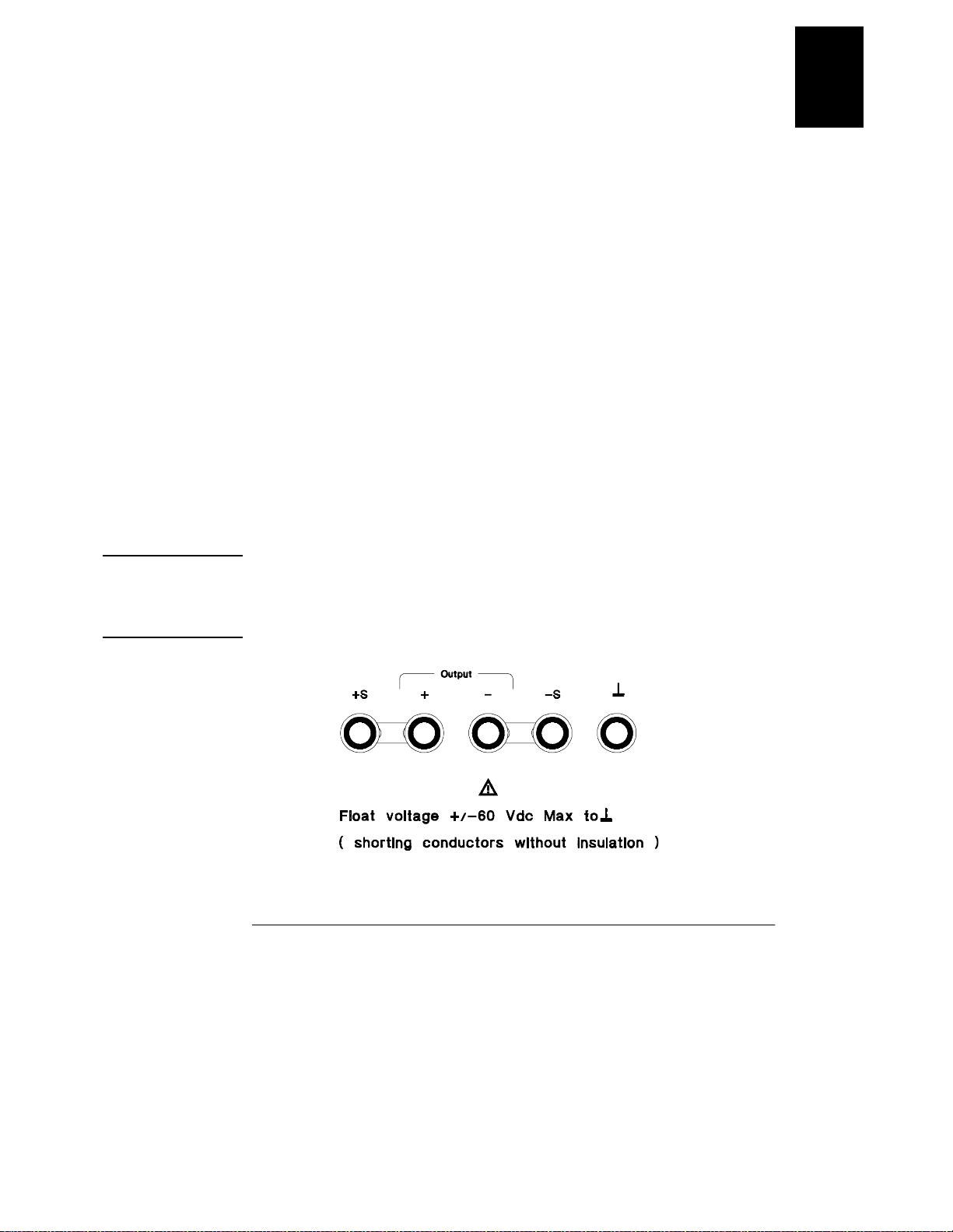
Connections to t he power supply ’ s outpu t and to chas sis ground a re made to binding
posts on the front panel and to the rear output terminals.
Warning Floating the power supply output mo re than ±60 Vdc from the chassis presents an
electric shock hazard to the operator . Do not float the outputs more than ±60 Vdc
when metal shorting bars without insulat ion are used to connect the (+) output to the
(+) sense and the (-) output to the (-) sense terminals.
17
Page 19
Chapter 1 General Information
Description
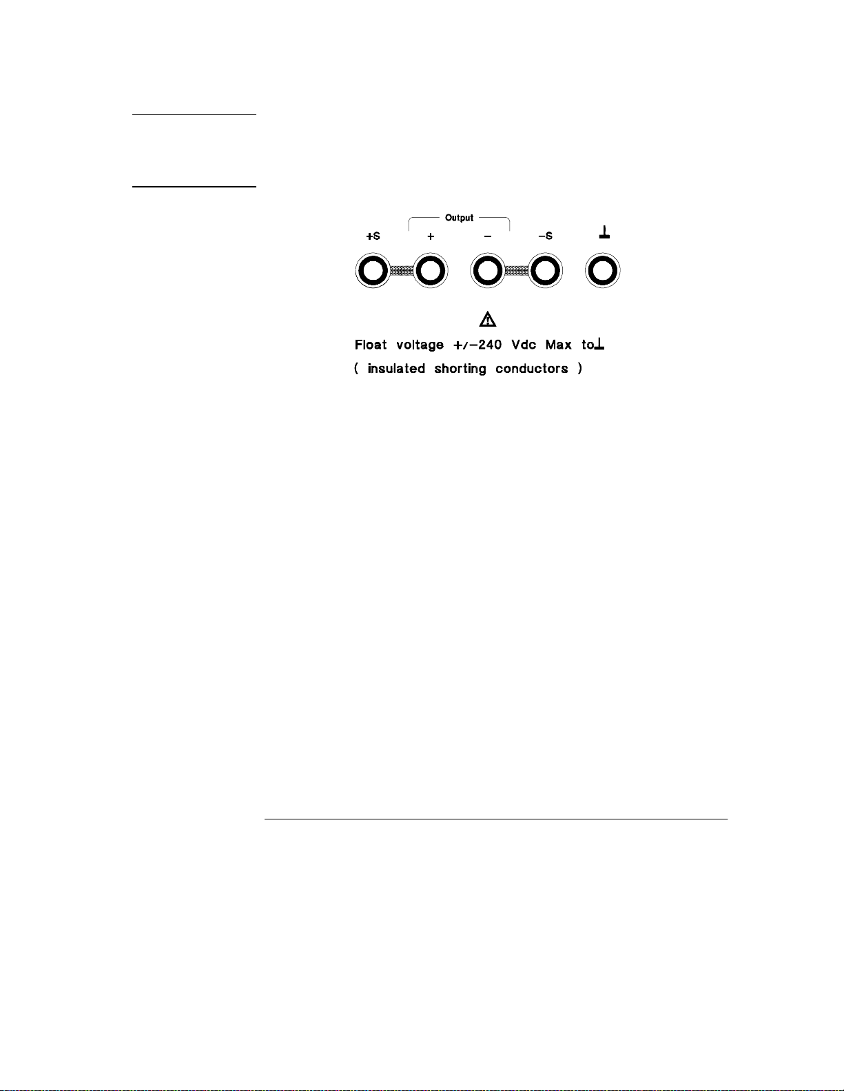
Warning Outputs can be float ed to maximum of ±240 Vdc provided that the metal short ing bars
without i nsulation are eith er replaced wi th ins ulated cond uctors or they are remove d
from the terminals so there is no operator access to the output conductors without
insulation. All fie ld wiring insulation must be adequate for the voltage present.
The power supply is shipped with a detachable , 3-wire grounding type power cord.
The ac line fuse is an extra ctor type on the rear panel. The power supply can be
calibrated from the front pa nel direc tly or with a c ontroller ove r the HP-IB or RS-232
interface using calibration commands. Correction factors are stored in nonvolatile
memory and are used during output programming. Calibration from the front panel
or a control le r eli minat e the need to remov e the top c over or even t he ne ed to remove
the power supply from your system cabinet. You can guard against unauthorized
calibration by using the “Secured” cal ibration protection function.
18
Page 20

Chapter 1 General Information
Installation
Installation
Initial In spection
When you receive your power s upply, inspect it for any obvious dam age that may
have occurred during s hipment. If any damage is found, notify the carrier and the
nearest HP Sales Office immediately. W arranty informat ion is shown in the fr ont of
this manual.
Keep the origina l pac king materials in case the power supply has to be returned to
Hewlett-Pack ard in the future. If you return th e power supply for servi ce, attach a tag
identifying the owner and model number. Also include a brief description of the
problem.
Mechanical Check
This check confirm s t hat th ere are no b roken ke ys or knob, that t he ca binet and panel
surfaces are free of dents and s cratches, and that t he display is not s cratched or c racked.
Electrical Check
Chapter 2 describ es an initial operatio n pr ocedure which, when succes sfully
completed, verifies to a high lev el of confidence that th e power supply is operating
in accor dance with its specifica tions. Detailed electrical verification procedures are
included in the Servic e G ui de.
1
Cooling and Location
Cooling
The power supply can operate without loss of performance within th e temperature
range of 0 °C to 40 °C, and with derated output current from
40 °C to 55 °C. A fan cools the power supply by drawi ng air through the rear panel
and exhausti ng it out the sides. Usi ng an HP rack mount will not impede the flow of air .
Bench Operation
Your power supply must be install ed in a location that al lows sufficient space at the
sides and rear of the power supp ly for adequate air circulation. The rubber bumpers
must be removed for rack mounting.
19
Page 21
Chapter 1 General Information
Installation
Rack Mounting
The power supply can be mounted in a standard 19-inch rack cabinet using one of
three option al kit s avai lable . A r ack-mounti ng ki t for a single instru ment i s ava ilabl e
as Option 1CM (P/N 506 3-9243). Inst allatio n instruct ions and har dware are includ ed
with each rack-mounting kit. Any HP System II instrument of the same size can be
rack-mounted beside the HP E3633A or E3634A DC power supply.
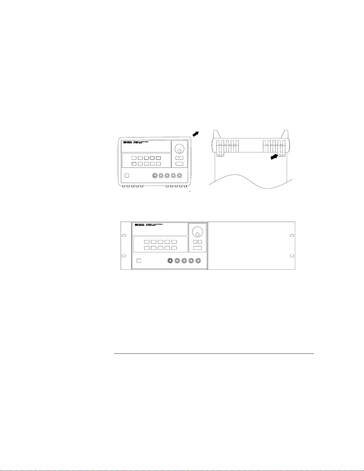
Remove the front and rear bumpers before rack-mounting the power supply.
To remove the rubber bumper, stretch a corner and then slide it off.
T
o rack mount a single instrument, order ada pter ki t 5063-9243.
20
Page 22
Chapter 1 General Information
Installation
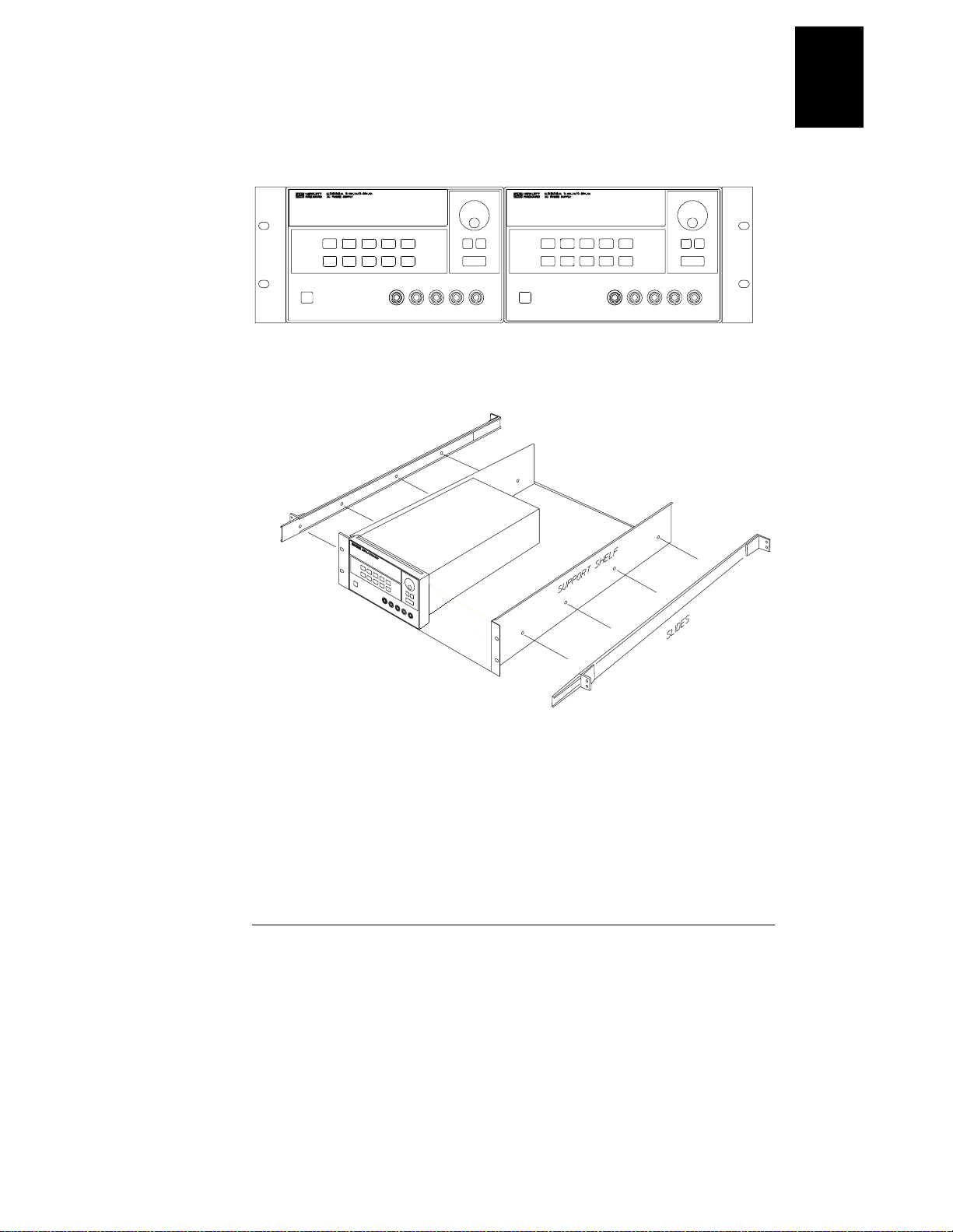
T o rack mount two instrument side-by-side, order lock-link kit 5061-9694
and flange kit 5063-9214.
1
To install one or two instruments in a sliding support shelf, order shelf
5063-9256, and slide kit 1494-0015.
21
Page 23

Chapter 1 General Information
Input Power Requirements
Input Power Requirements
You can operate your power supply from a nominal 100 V, 115 V, or 230 V single
phase ac power source at 47 to 63 Hz. An indication on the rear panel s hows the
nominal input voltage set for the power supply at the factory. If necessary, you can
change the power-line voltage setting according to the instructions on the next page .
Power-Line Cord
The power supply is shippe d from the factory with a power-line cord that has a plug
appropriate for your locatio n. Contac t the neare st HP Sales and Servi ce Offic e if the
wrong power-lin e cord is included with your power su pply. Your power supply is
equipped with a 3-wi re grounding type power cord; the third conductor being the
ground. The p ower supply i s grounded only when the power-line cord is plugge d into
an appropria te receptac le. Do not o perate your p ower supply withou t adequate cabinet
ground connection.
Power-Line Voltage Selection
Power-line voltage selec tion is accomplished by adjusting two components:
power-line v oltage se lector and power-li ne fuse on t he powe r-li ne m odule of the re ar
panel. To change the power-line voltage, proceed as follows:
22
Page 24

Chapter 1 General Information
Input Power Requirements
1
4 Remove the power cor d . Remove the
fuse-holder assembly with a flat-blade
screwdriver from the rear panel.
6 Rotate the power-line voltage selector
until the correct voltage appears.
5 Install the correct line fuse. Remove
the power-line voltage selector from the
power-line module.
100 or 115 Vac, 6.3 AT fus e
230 Vac, 3.1 5 A T fuse
7 Replace the pow er-line voltage selector
and the fuse-holder assembly in the rear
panel.
100, 115, or 230 Vac
23
Page 25

Chapter 1 General Information
Input Power Requirements
24
Page 26

2
Initial Operation
Page 27

Initial Operation
7KHUH#DUH#WKUHH#EDVLF#WHVWV#LQ#WKLV#FKDSWHU1#7KH#DXWRPDWLF#SRZHU0RQ#WHVW#
LQFOXGHV#D#VHOI0WHVW#WKDW#FKHFNV#WKH#LQWHUQDO#PLFURSURFHVVRUV#DQG#DOORZV#WKH#
XVHU#YLVXDOO\#WR#FKHFN#WKH#GLVSOD\1#7KH#RXWSXW#FKHFN#HQVXUHV#WKDW#WKH#SRZHU#
VXSSO\#GHYHORSV#LWV#UDWHG#RXWSXWV#DQG#SURSHUO\#UHVSRQGV#WR#RSHUDWLRQ#IURP#WKH#
IURQW#SDQHO1#)RU#FRPSOHWH#SHUIRUPDQFH#DQG2RU#YHULILFDWLRQ#WHVWV/#UHIHU#WR#WKH#
6HUYLFH#*XLGH.
7KLV#FKDSWHU#LV#LQWHQGHG#IRU#ERWK#WKH#H[SHULHQFHG#DQG#WKH#LQH[SHULHQFHG#XVHU#
EHFDXVH#LW#FDOOV#DWWHQWLRQ#WR#FHUWDLQ#FKHFNV#WKDW#VKRXOG#EH#PDGH#SULRU#WR#
RSHUDWLRQ1
7KURXJKRXW#WKLV#FKDSWHU#WKH#NH\#WR#EH#SUHVVHG#LV#VKRZQ#LQ#WKH#OHIW#PDUJLQ1
26
Page 28
Chapter 2 Initial Operation
Preliminary Checkout
Preliminary Che ckout
7KH#IROORZLQJ#VWHSV#KHOS#\RX#YHULI\#WKDW#WKH#SRZHU#VXSSO\#LV#UHDG\#IRU#XVH1
4 &KHFN#WKH#OLVW#RI#VXSSOLHG#LWHPV1
9HULI\#WKDW#\RX#KDYH#UHFHLYHG#WKH#IROORZLQJ#LWHPV#ZLWK#\RXU#SRZHU#VXSSO\1#,I#
DQ\WKLQJ#LV#PLVVLQJ/#FRQWDFW#\RXU#QHDUHVW#+HZOHWW03DFNDUG#6DOHV#2IILFH1
##2QH#SRZHU#FRUG#IRU#\RXU#ORFDWLRQ1
##7KLV#8VHUªV#*XLGH1
##2QH#6HUYLFH#*XLGH1
##&HUWLILFDWH#RI#&DOLEUDWLRQ1
5 9HULI\#WKH#SRZHU0OLQH#YROWDJH#VHWWLQJ#RQ#WKH#UHDU#SDQHO1
7KH#SRZHU0OLQH#YROWDJH#LV#VHW#WR#WKH#SURSHU#YDOXH#IRU#\RXU#FRXQWU\#ZKHQ#WKH#
SRZHU#VXSSO\#LV#VKLSSHG#IURP#WKH#IDFWRU\1#&KDQJH#WKH#YROWDJH#VHWWLQJ#LI#LW#LV#QRW#
FRUUHFW1#7KH#VHWWLQJV#DUH=#433/#448/#RU#563#9DF 1
6 9HULI\#WKDW#WKH#FRUUHFW#SRZHU0OLQH#IXVH#LV#LQVWDOOHG1
7KH#FRUUHFW#IXVH#LV#LQVWDOOHG#IRU#\RXU#FRXQWU\#ZKHQ#WKH#SRZHU#VXSSO\#LV#VKLSSHG#
IURP#WKH#IDFWRU\1#)RU#433#RU#448#9DF#RSHUDWLRQ/#\RX#PXVW#XVH#D#916 #$7#IXVH1#)RU#
563#9DF#RSHUDWLRQ/#\RX#PXVW#XVH#D#6148#$7#IXVH1
7 &RQQHFW#WKH#SRZHU0OLQH#FRUG#DQG#WXUQ#RQ#\RXU#SRZHU#VXSSO\1
7KH#IURQW0SDQHO#GLVSOD\#ZLOO#OLJKW#XS#DQG#D#SRZHU0RQ#VHOI0WHVW#RFFXUV#
DXWRPDWLFDOO\#ZKHQ#\RX#WXUQ#RQ#WKH#SRZHU#VXSSO\1#
6HH#©©3RZHU0/LQH#9ROWDJH#6HOHFWLRQªª/#VWDUWLQJ#RQ#SDJH#55#LQ#FKDSWHU#4#LI#\RX#
QHHG#WR#FKDQJH #WKH#SRZHU0OLQH#YROWDJH#RU#WKH#SRZHU0OLQH#IXVH1
2
7R#UHSODFH#WKH#916#$7#IXVH/#RUGHU#+3#SDUW#QXPEHU#5443043631
7R#UHSODFH#WKH#6148#$7#IXVH/#RUGHU#+3#SDUW#QXPEHU#5443043641
27
Page 29

Chapter 2 Initial Operation
3RZHU02Q#&KHFNRXW
Power-On Checkout
7KH#SRZHU0RQ#WHVW#LQFOXGHV#DQ#DXWRPDWLF#VHOI0WHVW#WKDW#FKHFNV#WKH#LQWHUQDO#
PLFURSURFHVVRUV#DQG#DOORZV#WKH#XVHU#YLVXDOO\#WR#FKHFN#WKH#GLVSOD\1#<RX#ZLOO#
REVHUYH#WKH#IROORZLQJ#VHTXHQFH#RQ#WKH#GLVSOD\#DIWHU#SUHVVLQJ#WKH#IURQW#SDQHO#
SRZHU#VZLWFK#WR#RQ1
4 7KH#IURQW0SDQHO#GLVSOD\#ZLOO#OLJKW#XS#EULHIO\#ZKLOH#WKH#LQVWUXPHQW#
SHUIRUPV#LWV#SRZHU0RQ#VHOI0WHVW1
7R#UHYLHZ#WKH#SRZHU0RQ#GLVSOD\#ZLWK#DOO#DQQXQFLDWRUV#WXUQHG#RQ/#KROG#GRZQ#
Display
#NH\#DV#\RX#WXUQ#RQ#WKH#SR ZHU #VXSSO\1
Limit
5 7KH#+30,%#DGGUHVV#RU#560565#LV#DOVR#GLVSOD\HG#IRU#DERXW#RQH#VHFRQG1
$''5ûìçû(orû56ïêéê)
7KH#+30,%#DGGUHVV#LV#VHW#WR#©©8ªª#ZKHQ#WKH#SRZHU#VXSSO\#LV#VKLSSHG#IURP#WKH#
IDFWRU\#IRU#UHPRWH#LQWHUIDFH#FRQILJXUDWLRQ1#,I#WKLV#LV#QRW#WKH#ILUVW#WLPH#WKH#SRZHU#
VXSSO\#LV#WXUQHG#RQ/#D#GLIIHUHQW#LQWHUIDFH#+ 560565,#RU#D#GLIIHUHQW#+30,%#DGGUHVV#
PD\#DSSHDU1
6HH#%5HPRWH#,QWHUIDFH#&RQILJXUDWLRQ%#LQ#FKDS WHU#6#VWDUWLQJ#RQ#SDJH#8;#LI#\RX#
QHHG#WR#FKDQJH #WKH#UHPRWH#LQWHUIDFH#FRQILJXUDWLRQ1
Output
On/Off
Note
6 7KH#§
8V¨-#RU#§25V¨--/#§OVP¨/#§OCP¨#DQG#§OFF¨#DQQXQFL DW RUV#DUH#RQ1#
$OO#RWKHUV#DUH#RII1
7KH#SRZHU#VXSSO\#ZLOO#JR#LQWR#WKH#SRZHU0RQ#2#UHVHW#VWDWH>#WKH#RXWSXW#LV#GLVDEOHG#
+WKH#
OFF#DQQXQFLDWRU#WXUQV#RQ,>#WKH#;253$-#RU#5892:$--#UDQJH#LV#VHOHFWHG#+WKH#
8V-#RU#25V--#DQQXQFLDWRU#WXUQV#RQ,>#DQG#WKH#NQRE#LV#VHOHFWHG#IRU#YROWDJH#
FRQWURO1#1RWLFH#WKDW#WKH#
OVP#DQG#OCP#DQQXQFLDWRU#DOVR#WXUQ#RQ1
7#(QDEOH#WKH#RXWSXWV1
7KH#
OFF#DQQXQFLDWRU#WXUQV#RII#DQG#WKH#8V-#RU#25V--/#OVP/#OCP/#DQG#CV#
DQQXQFLDWRUV#DUH#OLW1#7KH#EOLQNLQJ#GLJLW#FDQ#EH#DGMXVWHG#E\#WXUQLQJ#WKH#NQRE1#
1RWLFH#WKDW#WKH#GLVSOD\#LV#LQ#WKH#PHWHU#PRGH1#©©0HWHU#PRGHªª#PHDQV#WKDW#WKH#
GLVSOD\#VKRZV#WKH#DFWXDO#RXWSXW#YROWDJH#DQG#FXUUHQW1
If the power supply detects an error during power-on self-test, the
ERROR
annunciator will turn on. See "Erro r Messages" for more inform ation starting on page
123 in chapter 5
*For HP E3633A Model **For HP E3634A Model
28
Page 30

Power
Output
On/Off
Chapter 2 Initial Operation
Output Checkout
Output Checkout
7KH#IROORZLQJ#SURFHGXUHV#FKHFN#WR#HQVXUH#WKDW#WKH#SRZHU#VXSSO\#GHYHORSV#LWV#
UDWHG#RXWSXWV#DQG#SURSHUO\#UHVSRQGV#WR#RSHUDWLRQ#IURP#WKH#IURQW#SDQHO1#)RU#
FRPSOHWH#SHUIRUPDQFH#DQG#YHULILFDWLRQ#WHVWV/#UHIHU#WR#WKH#6HUYLFH#*XLGH1
)RU#HDFK#VWHS/#XVH#WKH#NH\V#VKRZQ#RQ#WKH#OHIW#PDUJLQV1
Voltage Output Checkout
7KH#IROORZLQJ#VWHSV#YHULI\#EDVLF#YROWDJH#IXQFWLRQV#ZLWK#QR#ORDG1
4 7XUQ#RQ#WKH#SRZHU#VXSSO\1
7KH#SRZHU#VXSSO\#ZLOO#JR#LQWR#WKH#SRZHU0RQ#2#UHVHW#VWDWH>#WKH#RXWSXW#LV#GLVDEOHG#
OFF
+WKH#
8V
FRQWURO1
5 (QDEOH#WKH#RXWSXWV1
7KH#
DQQXQFLDWRUV#DUH#OLW1#7KH#EOLQNLQJ#GLJLW#FDQ#EH#DGMXVWHG#E\#WXUQLQJ#WKH#NQRE1#
1RWLFH#WKDW#WKH#GLVSOD\#LV#LQ#WKH#PHWHU#PRGH1#©©0HWHU#PRGHªª#PHDQV#WKDW#WKH#
GLVSOD\#VKRZV#WKH#DFWXDO#RXWSXW#YROWDJH#DQG#FXUUHQW1
#DQQXQFLDWRU#WXUQV#RQ,>#WKH#;9253$-#RU#5892:$--#UDQJH#LV#VHOHFWHG#+WKH#
25V
-#RU#
--#DQQXQFLDWRU#WXUQV#RQ,>#DQG#WKH#NQRE#LV#VHOHFWHG#IRU#YROWDJH#
OFF
#DQQXQFLDWRU#WXUQV#RII#DQG#WKH#8V-#RU#
25V
OVP/#OCP
--/#
/#DQG#CV#
2
6 &KHFN#WKDW#WKH#IURQW0SDQHO#YROWPHWHU#SURSHUO\#UHVSRQGV#WR#NQRE#
FRQWURO#IRU#WKH#;9253$-#RU#5892:$--#UDQJH1
7XUQ#WKH#NQRE#FORFNZLVH#RU#FRXQWHU#FORFNZLVH#WR#FKHFN#WKDW#WKH#YROWPHWHU#
UHVSRQGV#WR#NQRE#FRQWURO#DQG#WKH#DPPHWHU#LQGLFDWHV#QHDUO\#]HUR1
4
7 (QVXUH#WKDW#WKH#YROWDJH#FDQ#EH#DGMXVWHG#IURP#]HUR#WR#WKH#IXOO#UDWHG#
YDOXH1
$GMXVW#WKH#NQRE#XQWLO#WKH#YROWPHWHU#LQGLFDWHV#3#YROWV#DQG#WKHQ#DGMXVW#WKH#NQRE#
XQWLO#WKH#YROWPHWHU#LQGLFDWHV#©©
4
<RX#FDQ#XVH#WKH#UHVROXWLRQ#VHOHFWLRQ#NH\V#WR#PRYH#WKH#EOLQNLQJ#GLJLW#WR#WKH#
8.0
#YROWVªª-#RU#©©
25.0
#YROWVªª--
ULJKW#RU#OHIW#ZKHQ#VHWWLQJ#WKH#YROWDJH1
*For HP E3633A Model **For HP E3634A Model
29
Page 31

Power
Output
On/Off
Display
Limit
Voltage
Current
Chapter 2 Initial Operation
Output Checkout
Current Output Checkout
7KH#IROORZLQJ#VWHSV#FKHFN#EDVLF#FXUUHQW#IXQFWLRQV#ZLWK#D#VKRUW#DFURVV#WKH#
SRZHU#VXSSO\ªV#RXWSXW1
4 7XUQ#RQ#WKH#SRZHU#VXSSO\1
7KH#SRZHU#VXSSO\#ZLOO#JR#LQWR#WKH#SRZHU0RQ#2#UHVHW#VWDWH>#WKH#RXWSXW#LV#GLVDEOHG#
OFF
+WKH#
8V
FRQWURO1
5 &RQQHFW#D#VKRUW#DF URVV#+.,#DQG#+0,#RXWSXW#WHUPLQDOV#ZLWK#DQ#LQVXODWHG#
WHVW#OHDG1
8VH#D#ZLUH#VL]H#VXIILFLHQW#WR#KDQGOH#WKH#PD[LPXP#FXUUHQW#+6HH#%7DEOH #:04#:LUH#
5DWLQJ%#RQ#SDJH#486#LQ#FKDSWHU#:,1
6 (QDEOH#WKH#RXWSXW1
7KH#
DQQXQFLDWRUV#DUH#OLW1#7KH#
UHVLVWDQFH#RI#WKH#WHVW#OHDG1#7KH#EOLQNLQJ#GLJLW#FDQ#EH#DGMXVWHG#E\#WXUQLQJ#WKH#
NQRE1#1RWLFH#WKDW#WKH#GLVSOD\#LV#LQ#WKH#PHWHU#PRGH1#©©0HWHU#PRGHªª#PHDQV#WKDW#
WKH#GLVSOD\#VKRZV#WKH#DFWXDO#RXWSXW#YROWDJH#DQG#FXUUHQW1
7 $GMXVW#WKH#YROWDJH#OLPLW#YDOXH#WR#413#YROW1
6HW#WKH#GLVSOD\#WR#WKH#OLPLW#PRGH#+ WKH#
WKH#YROWDJH#OLPLW#WR#413#YROW#WR#DVVXUH#&&#RSHUDWLRQ1#7KH#
WXUQ#RQ1#7R#JR#EDFN#WR#QRUPDO#PRGH/#SUHVV#WKH##NH\#DJDLQ#RU#OHW#WKH#GLVSOD\#
WLPH#RXW#IRU#VHYHUDO#VHFRQGV#1
##
8 6HW#WKH#NQRE#WR#WKH#FXUUHQW#FRQWURO#WR#FKHFN#WKDW#WKH#IURQW0SDQHO#
DPPHWHU#SURSHUO\#UHVSRQGV#WR#NQRE#FRQWURO1
7XUQ#WKH#NQRE#FORFNZLVH#RU#FRXQWHU#FORFNZLVH#ZKHQ#WKH#GLVSOD\#LV#LQ#WKH#PHWHU#
PRGH#+WKH#
FRQWURO#DQG#WKH#YROWPHWHU#LQGLFDWHV#QHDUO\#]HUR#+WKH#YROWPHWHU#ZLOO#VKRZ#WKH#
YROWDJH#GURS#FDXVHG#E\#WKH#WHVW#OHDG,1
#DQQXQFLDWRU#WXUQV#RQ,>#WKH#;9253$-#RU#5892:$--#UDQJH#LV#VHOHFWHG#+WKH#
25V
-#RU#
--#DQQXQFLDWRU#WXUQV#RQ,>#DQG#WKH#NQRE#LV#VHOHFWHG#IRU#YROWDJH#
OFF
#DQQXQFLDWRU#WXUQV#RII#DQG#WKH#8V-#RU#
CV
#RU#CC#DQQXQFLDWRU#WXUQV#RQ#GHSHQGLQJ#RQ#WKH#
Limit
#DQQXQFLDWRU#LV#RII,1#&KHFN#WKDW#WKH#DPPHWHU#UHVSRQGV#WR#NQRE#
Limit
25V
OVP
--/#
/#DQG#
#DQQXQFLDWRU#ZLOO#EH#EOLQNLQJ,1#$GMXVW#
Display
Limit
CC
OCP
#DQQXQFLDWRU#ZLOO#
#
*For HP E3633A Model **For HP E3634A Model
30
Page 32

Chapter 2 Initial Operation
Output Checkout
4
9 (QVXUH#WKDW#WKH#FXUUHQW#FDQ#EH#DGMXVWHG#IURP#]HUR#WR#WKH#IXOO#UDWHG#
YDOXH1
$GMXVW#WKH#NQRE#XQWLO#WKH#DPPHWHU#LQGLFDWHV#3 #DPSV#DQG#WKHQ#XQWLO#WKH#DPPHWHU#
LQGLFDWHV#5313#DPSV-#RU#:13#DPSV--1#
2
: 7XUQ#RII#WKH#SRZHU#VXSSO\#DQG#UHPRYH#WKH#VKRUW#IURP#WKH#RXWSXW1
1
<RX#FDQ#XVH#WKH#UHVROXWLRQ#VHOHFWLRQ#NH\V#WR#PRYH#WKH#EOLQNLQJ#GLJLW#WR#WKH#
ULJKW#RU#OHIW#ZKHQ#VHWWLQJ#WKH#FXUUHQW1
Note If an error has been detec ted during the output ch ec kout procedures, the
annunciator will turn on. See "Erro r Messages" for more inform ation starting on page
123 in chapter 5
ERROR
*For HP E3633A Model **For HP E3634A Model
31
Page 33

Chapter 2 Initial Operation
Output Checkout
32
Page 34

3
Front-Panel Operation
Page 35

Front-Pane l Op er at ion
6R#IDU#\RX#KDYH#OHDUQHG#KRZ#WR#LQVWDOO#\RXU#SRZHU#VXSSO\#DQG#SHUIRUP#LQLWLDO#
RSHUDWLRQ1#'XULQJ#WKH#LQLWLDO#RSHUDWLRQ/#\RX#ZHUH#EULHIO\#LQWURGXFHG#WR#
RSHUDWLQJ#IURP#WKH#IURQW#SDQHO#DV#\RX#OHDUQHG#KRZ#WR#FKHFN#EDVLF#YROWDJH#DQG#
FXUUHQW#IXQFWLRQV1#7KLV#FKDSWHU#ZLOO#GHVFULEH#LQ#GHWDLO#WKH#XVH#RI#WKHVH#IURQW0
SDQHO#NH\V#DQG#VKRZ#KRZ#WKH\#DUH#XVHG#WR#DFFRPSOLVK#SRZHU#VXSSO\#RSHUDWLRQ1
‡)URQW03DQHO#2SHUDWLRQ#2YHUYLHZ/#RQ#SDJH#68
‡ &RQVWDQW#9ROWDJH#2SHUDWLRQ/#VWDUWLQJ#RQ#SDJH#69
‡ &RQVWDQW#&XUUHQW#2SHUDWLRQ/#VWDUWLQJ#RQ#SDJH#6;
‡6WRULQJ#DQG#5HFDOOLQJ#2SHUDWLQJ#6WDWHV/#VWDUWLQJ#RQ#SDJH#73
‡ 3URJUDPPLQJ#2YHUYROWDJH#3URWHFWLRQ/#VWDUWLQJ#RQ#SDJH#75
‡ 3URJUDPPLQJ#2YHUFXUUHQW#3URWHFWLRQ/#VWDUWLQJ#RQ#SDJH#79
‡5HPRWH#9ROWDJH#6HQVLQJ#DW#WKH#IURQW#DQG#UHDU#SDQHO/#VWDUWLQJ#RQ#SDJH#7<
‡ 'LVDEOLQJ#WKH#2XWSXW/#RQ#SDJH#85
‡ 'LVDEOLQJ#WKH#2XWSXW#8VLQJ#DQ#([WHUQDO#5HOD\/#RQ#SDJH#86
‡ .QRE#/RFNLQJ/#RQ#SDJH#86
‡6\VWHP05HODWHG#2SHUDWLRQV/#VWDUWLQJ#RQ#SDJH#87
‡5HPRWH#,QWHUIDFH#&RQILJXUDWLRQ/##VWDUWLQJ#RQ#SDJH#8;
‡+30,%#,QWHUIDFH#&RQILJXUDWLRQ/#RQ#SDJH#96
‡560565#,QWHUIDFH#&RQILJXUDWLRQ/#VWDUWLQJ#RQ#SDJH#97
‡ &DOLEUDWLRQ#2YHUYLHZ/##VWDUWLQJ#RQ#SDJH#9;
7KURXJKRXW#WKLV#FKDSWHU#WKH#NH\#WR#EH#SUHVVHG#LV#VKRZQ#LQ#WKH#OHIW#PDUJLQ1
Note See "Error Mes sages ", s tarti ng on pag e 12 3 in chapte r 5 i f you e ncounte r any error s
during front -panel operation.
34
Page 36

Chapter 3 Front-Panel Operation
Front-Panel Operation Overview
Front-Panel Operation Overview
7KH#IROORZLQJ#VHFWLRQ#GHVFULEHV#DQ#RYHUYLHZ#RI#WKH#IURQW0SDQHO#NH\V#EHIRUH#
RSHUDWLQJ#\RXU#SRZHU#VXSSO\1
‡7KH#SRZHU#VXSSO\#LV#VKLSSHG#IURP#WKH#IDFWRU\#FRQILJXUHG#LQ#WKH#IURQW0SDQHO#
RSHUDWLRQ#PRGH1#$W#SRZHU0RQ/#WKH#SRZHU#VXSSO\#LV#DXWRPDWLFDOO\#VHW#WR#
RSHUDWH#LQ#WKH#IURQW0SDQHO#RSHUDWLRQ#PRGH1#:KHQ#LQ#WKLV#PRGH/#WKH#IURQW0
SDQHO#NH\V#FDQ#EH#XVHG1#:KHQ#WKH#SRZHU#VXSSO\#LV#LQ#UHPRWH#RSHUDWLRQ#PRGH/#
\RX#FDQ#UHWXUQ#WR#IURQW0SDQHO#RSHUDWLRQ#PRGH#DW#DQ\#WLPH#E\#SUHVVLQJ#WKH#
Store
+Local
Local
FRPPDQG1#$#FKDQJH#EHWZHHQ#IURQW0SDQHO#DQG#UHPRWH#RSHUDWLRQ#PRGHV#ZLOO#
QRW#UHVXOW#LQ#D#FKDQJH#LQ#WKH#RXWSXW#SDUDPHWHUV1
‡7KH#SRZHU#VXSSO\#KDV#WZR#RXWSXW#UDQJHV1#7KLV#IHDWXUH#DOORZV#PRUH#YROWDJH#
DW#D#ORZHU#FXUUHQW#RU#PRUH#FXUUHQW#DW#D#ORZHU#YROWDJH1#7KH#GHVLUHG#RXWSXW#
UDQJH#LV#VHOHFWHG#IURP#WKH#IURQW#SDQHO#RU#RYHU#WKH#UHPRWH#LQWHUIDFHV1#7KH#
20V
RU#
WKH#SUHVHQWO\#VHOHFWHG#UDQJH1
‡:KHQ#\RX#SUHVV##NH\#+WKH#
SRZHU#VXSSO\#JRHV#WR#WKH#OLPLW#PRGH#DQG#WKH#SUHVHQW#OLPLW#YDOXHV#ZLOO#EH#
GLVSOD\HG1#,Q#WKLV#PRGH/#\RX#FDQ#DOVR#REVHUYH#WKH#FKDQJH#RI#WKH#OLPLW#YDOXHV#
ZKHQ#DGMXVWLQJ#WKH#NQRE1#,I#\RX#SUHVV#WKH##NH\#DJDLQ#RU#OHW#WKH#GLVSOD\#
WLPH0RXW#DIWHU#VHYHUDO#VHFRQGV/#WKH#SRZHU#VXSSO\#ZLOO#UHWXUQ#WKH#GLVSOD\#WR#
WKH#PHWHU#PRGH#+WKH#
RXWSXW#YROWDJH#DQG#FXUUHQW#ZLOO#EH#GLVSOD\HG1
‡7KH#RXWSXW#RI#WKH#SRZHU#VXSSO\#FDQ#EH#HQDEOHG#RU#GLVDEOHG#IURP#WKH#IURQW#
SDQHO#E\#SUHVVLQJ##NH\1#:KHQ#WKH#RXWSXW#LV#RII/#WKH#
WXUQV#RQ#DQG#WKH#RXWSXW#LV#GLVDEOHG1
‡7KH#GLVSOD\#SURYLGHV#WKH#SUHVHQW#RSHUDWLQJ#VWDWXV#RI#WKH#SRZHU#VXSSO\#ZLWK#
DQQXQFLDWRUV#DQG#DOVR#LQIRUPV#WKH#XVHU#RI#HUURU#FRGHV1#)RU#H[DPSOH/#WKH#
SRZHU#VXSSO\#LV#RSHUDWLQJ#LQ#&9#PRGH#LQ#WKH#;9253$-#RU#5892:$--#UDQJH#DQG#
FRQWUROOHG#IURP#WKH#IURQW#SDQHO/#WKHQ#WKH#
ZLOO#WXUQ#RQ1#,I/#KRZHYHU/#WKH#SRZHU#VXSSO\#LV#UHPRWHO\#FRQWUROOHG/#WKH#
DQQXQFLDWRU#ZLOO#DOVR#WXUQ#RQ/#DQG#ZKHQ#WKH#SRZHU#VXSSO\#LV#EHLQJ#DGGUHVVHG#
RYHU#+30,%#LQWHUIDFH/#WKH#
$QQXQFLDWRUVª#RQ#SDJH#8#IRU#PRUH#LQIRUPDWLRQ1
,#NH\#LI#\RX#GLG#QRW#SUHYLRXVO\#VHQG#WKH#IURQW0SDQHO#ORFNRXW#
25V
#IRU#WKH#(6966$#DQG#
Display
Limit
Limit
Output
On/Off
#DQQXQFLDWRU#WXUQV#RII,1#,Q#WKLV#PRGH/#WKH#DFWXDO#
Adrs
50V
#RU#
#IRU#WKH#(6967$#DQQXQFLDWRU#LQGLFDWHV#
Limit
#DQQXQFLDWRU#EOLQNV,/#WKH#GLVSOD\#RI#WKH#
Display
Limit
OFF
CV
#DQG#8V-#RU#
25V
#DQQXQFLDWRU#ZLOO#WXUQ#RQ1#6HH#§'LVSOD\#
8V
#DQQXQFLDWRU#
--##DQQXQFLDWRUV#
Rmt
3
#
#
*For HP E3633A Model **For HP E3634A Model
35
Page 37

Power
Display
Limit
Chapter 3 Front-Panel Operation
Constant Voltage Operation
Constant Voltage Operation
7R#VHW#XS#WKH#SRZHU#VXSSO\#IRU#FRQVWDQW#YROWDJH#+&9,#RSHUDWLRQ/#SURFHHG#DV#
IROORZV1
‡)URQW0SDQHO#RSHUDWLRQ=
4 &RQQHFW#D#ORDG#WR#WKH#RXWSXW#WHUPLQDOV1
:LWK#SRZHU0RII/#FRQQHFW#D#ORDG#WR#WKH#+.,#DQG#+0,#RXWSXW#WHUPLQDOV1
5 7XUQ#RQ#WKH#SRZHU#VXSSO\1
7KH#SRZHU#VXSSO\#ZLOO#JR#LQWR#WKH#SR ZHU0RQ#2#UHVHW#VWDWH>#WKH#RXWSXW#LV#GLVDEOHG#
OFF
+WKH#
8V
3UHVV#-#RU#--#NH\#WR#RSHUDWH#WKH#SRZHU#VXSSO\#LQ#WKH#539243$-#RU#
83927$--#UDQJH#EHIRUH#SURFHHGLQJ#WR#WKH#QH[W#VWHS1#7KH#
DQQXQFLDWRU#WXUQV#RQ1
6 6HW#WKH#GLVSOD\#WR#WKH#OLPLW#PRGH1
1RWLFH#WKDW#WKH#
OLPLW#PRGH1#:KHQ#WKH#GLVSOD\#LV#LQ#WKH#OLPLW#PRGH/#\RX#FDQ#VHH#WKH#YROWDJH#DQG#
FXUUHQW#OLPLW#YDOXHV#RI#WKH#SRZHU#VXSSO\1
#DQQXQFLDWRU#WXUQV#RQ,>#WKH#;9253$-#RU#5892:$--#UDQJH#LV#VHOHFWHG#+WKH#
25V
-#RU#
--#DQQXQFLDWRU#WXUQV#RQ,>#DQG#WKH#NQRE#LV#VHOHFWHG#IRU#YROWDJH#FRQWURO1
20V,10A 50V,4A
20V
-#RU#
Limit
#DQQXQFLDWRU#EOLQNV/#LQGLFDWLQJ#WKDW#WKH#GLVSOD\#LV#LQ#WKH#
50V
--#
Voltage
Current
,Q#FRQVWDQW#YROWDJH#PRGH/#WKH#YROWDJH#YDOXHV#EHWZHHQ#WKH#PHWHU#DQG#
OLPLW#PRGHV#DUH#WKH#VDPH/#EXW#WKH#FXUUHQW#YDOXHV#DUH#QRW1#0RUHRYHU/#LI#WKH#
GLVSOD\#LV#LQ#WKH#PHWHU#PRGH/#\R X#FDQQRW#VHH#WKH#FKDQJH#RI#FXUUHQW#OLPLW#
YDOXH#ZKHQ#DGMXVWLQJ#WKH#NQRE1#:H#UHFRPPHQG #WKDW#\RX#VKRXOG#VHW#WKH#
GLVSOD\#WR#§OLPLW¨#PRGH#WR#VHH#WKH#FKDQJH#RI#FXUUHQW#OLPLW#YDOXH#LQ#WKH#
FRQVWDQW#YROWDJH#PRGH#ZKHQHYHU#DGMXVWLQJ#WKH#NQRE1
4
#
7 $GMXVW#WKH#NQRE#IRU#WKH#GHVLUHG#FXUUHQW#OLPLW1
&KHFN#WKDW#WKH#
Limit
#DQQXQFLDWRU#VWLOO#EOLQNV1#6HW#WKH#NQRE#IRU#FXUUHQW#FRQWURO1#
7KH#VHFRQG#GLJLW#RI#WKH#DPPHWHU#ZLOO#EH#EOLQNLQJ1#7KH#EOLQNLQJ#GLJLW#FDQ#EH#
FKDQJHG#XVLQJ#WKH#UHVROXWLRQ#VHOHFWLRQ#NH\V#DQG#WKH#EOLQNLQJ#GLJLW#FDQ#EH#
DGMXVWHG#E\#WXUQLQJ#WKH#NQRE1#$GMXVW#WKH#NQRE#WR#WKH#GHVLUHG#FXUUHQW#OLPLW1
4
<RX#FDQ#XVH#WKH#UHVROXWLRQ#VHOHFWLRQ#NH\V#WR#PRYH#WKH#EOLQNLQJ#GLJLW#WR#WKH#
ULJKW#RU#OHIW#ZKHQ#VHWWLQJ#FXUUHQW1
*For HP E3633A Model **For HP E3634A Model
36
Page 38

Chapter 3 Front-Panel Operation
Constant Voltage Operation
Voltage
Current
Display
Limit
Output
On/Off
4
8 $GMXVW#WKH#NQRE#IRU#WKH#GHVLUHG#RXWSXW#YROWDJH1
&KHFN#WKDW#WKH#
Limit
#DQQXQFLDWRU#VWLOO#EOLQNV1#6HW#WKH#NQRE#IRU#YROWDJH#FRQWURO1#
7KH#VHFRQG#GLJLW#RI#WKH#YROWPHWHU#ZLOO#EH#EOLQNLQJ1#&KDQJH#WKH#EOLQNLQJ#GLJLW#
XVLQJ#WKH#UHVROXWLRQ#VHOHFWLRQ#NH\V#DQG#DGMXVW#WKH#NQRE#WR#WKH#GHVLUHG#RXWSXW#
YROWDJH1
9 5HWXUQ#WR#WKH#PHWHU#PRGH1#
Display
3UHVV##NH\#RU#OHW#WKH#GLVSOD\#WLPH0RXW#DIWHU#VHYHUDO#VHFRQGV#WR#UHWXUQ#WR#
Limit
WKH#PHWHU#PRGH1#1RWLFH#WKDW#WKH#
Limit
#DQQXQFLDWRU#WXUQV#RII#DQG#WKH#GLVSOD\#
VKRZV#§287387#2))¨#PHVVDJH1
3
: (QDEOH#WKH#RXWSXW1
OFF
7KH#
OCP
#DQQXQFLDWRU#WXUQV#RII#DQG#WKH#8V-#+RU#
#DQG#CV#DQQXQFLDWRUV#DUH#OLW1#1RWLFH#WKDW#WKH#GLVSOD\#LV#LQ#WKH#PHWHU#PRGH1#
,Q#WKH#PHWHU#PRGH/#WKH#GLVSOD\#VKRZV#WKH#DFWXDO#RXWSXW#YROWDJH#DQG#FXUUHQW1
5HIHU#WR#§3URJUDPPLQJ#2YHUYROWDJH#3URWHFWLRQ¨#DQG#§3URJUDPPLQJ#
2YHUFXUUHQW#3URWHFWLRQ¨#VHFWLRQV/#VWDUWLQJ#RQ#SDJ H 75#DQG#SDJH 79#IRU#PRUH#
LQIRUPDWLRQ#RQ#
OVP
#DQG#
OCP
#DQQXQFLDWRUV1
; 9HULI\#WKDW#WKH#SRZHU#VXSSO\#LV#LQ#WKH#FRQVWDQW#YROWDJH#PRGH1
,I#\RX#RSHUDWH#WKH#SRZHU#VXSSO\#LQ#WKH#FRQVWDQW#YROWDJH#+&9,#PRGH/#YHULI\#WKDW#
CV
WKH#
#DQQXQFLDWRU#LV#OLW1#,I#WKH#CC#DQQXQFLDWRU#LV#OLW/#FKRRVH#D#KLJKHU#FXUUHQW#
OLPLW1
25V
--,#RU#
20V
-#+RU#
50V
--,/#
OVP
/#
Note During actua l CV operati on, if a load change cause s the curre nt limi t to be ex ceeded,
the power supply will automatically crossover to the constant current mode at the
preset current limit and the output voltage will drop proportionately.
‡5HPRWH#LQWHUIDFH#RSHUDWLRQ=
CURRent {<current>|MIN|MAX} Se t the current
VOLTage {<voltage>|MIN|MAX} Set the voltage
OUTPut ON Enable the output
4
<RX#FDQ#XVH#WKH#UHVROXWLRQ#VHOHFWLRQ#NH\V#WR#PRYH#WKH#EOLQNLQJ#GLJLW#WR#WKH#
ULJKW#RU#OHIW#ZKHQ#VHWWLQJ#YROWDJH1
*For HP E3633A Model **For HP E3634A Model
37
Page 39

Power
Display
Limit
Chapter 3 Front-Panel Operation
Constant Current Operation
Constant Current Ope ration
7R#VHW#XS#WKH#SRZHU#VXSSO\#IRU#FRQVWDQW#FXUUHQW#+&&,#RSHUDWLRQ/#SURFHHG#DV#
IROORZV1
‡)URQW0SDQHO#RSHUDWLRQ=
4 &RQQHFW#D#ORDG#WR#WKH#RXWSXW#WHUPLQDOV1
:LWK#SRZHU0RII/#FRQQHFW#D#ORDG#WR#WKH#+.,#DQG#+0,#RXWSXW#WHUPLQDOV1
5 7XUQ#RQ#WKH#SRZHU#VXSSO\1
7KH#SRZHU#VXSSO\#ZLOO#JR#LQWR#WKH#SR ZHU0RQ#2#UHVHW#VWDWH>#WKH#RXWSXW#LV#GLVDEOHG#
OFF
+WKH#
8V
7R#RSHUDWH#WKH#SRZHU#VXSSO\#LQ#WKH#539243$-#RU#83927$--#UDQJH/#SUHVV#-#
RU#--#NH\#EHIRUH#SURFHHGLQJ#WR#WKH#QH[W#VWHS1#7KH#
DQQXQFLDWRU#WXUQV#RQ1
6 6HW#WKH#GLVSOD\#WR#WKH#OLPLW#PRGH1#
1RWLFH#WKDW#WKH#
OLPLW#PRGH1#:KHQ#WKH#GLVSOD\#LV#LQ#WKH#OLPLW#PRGH/#\RX#FDQ#VHH#WKH#YROWDJH#DQG#
FXUUHQW#OLPLW#YDOXHV#RI#WKH#VHOHFWHG#VXSSO\1
#DQQXQFLDWRU#WXUQV#RQ,>#WKH#;9253$-#RU#5892:$--#UDQJH#LV#VHOHFWHG#+WKH#
25V
-#RU#
--#DQQXQFLDWRU#WXUQV#RQ,>#DQG#WKH#NQRE#LV#VHOHFWHG#IRU#YROWDJH#FRQWURO1
50V,4A
Limit
#DQQXQFLDWRU#EOLQNV/#LQGLFDWLQJ#WKDW#WKH#GLVSOD\#LV#LQ#WKH#
20V
-#RU#
50V
20V,10A
--#
,Q#FRQVWDQW#FXUUHQW#PRGH/#WKH#FXUUHQW#YDOXHV#EHWZHHQ#WKH#PHWHU#PRGH#
DQG#OLPLW#PRGH#DUH#WKH#VDPH/#EXW#WKH#YROWDJH#YDOXHV#DUH#QRW1#0RUHRYHU/#LI#
WKH#GLVSOD\#LV#LQ#WKH#PHWHU#PRGH/#\RX#FDQQRW#VHH#WKH#FKDQJH#RI#YROWDJH#
OLPLW#YDOXH#ZKHQ#DGMXVWLQJ#WKH#NQRE1#:H#UHFRPPHQG#WKDW#\RX#VKRXOG#VHW#
WKH#GLVSOD\#WR#§OLPLW¨#PRGH#WR #VHH#WKH#FKDQJH#RI#YROWDJH#OLPLW#YDOXH#LQ#WKH#
FRQVWDQW#FXUUHQW#PRGH#ZKHQHYHU#DGMXVWLQJ#WKH#NQRE1
4
7 $GMXVW#WKH#NQRE#IRU#WKH#GHVLUHG#YROWDJH#OLPLW1
&KHFN#WKDW#WKH#
Limit
#DQQXQFLDWRU#VWLOO#EOLQNV#DQG#WKH#VHFRQG#GLJLW#RI#YROWPHWHU#
EOLQNV#WR#LQGLFDWH#WKH#NQRE#LV#VHOHFWHG#IRU#YROWDJH#FRQWURO1#7KH#EOLQNLQJ#GLJLW#
FDQ#EH#FKDQJHG#XVLQJ#WKH#UHVROXWLRQ#NH\V#DQG#WKH#EOLQNLQJ#GLJLW#FDQ#EH#DGMXVWHG#
E\#WXUQLQJ#WKH#NQRE1#$GMXVW#WKH#NQRE#IRU#WKH#GHVLUHG#YROWDJH#OLPLW1
4
<RX#FDQ#XVH#WKH#UHVROXWLRQ#VHOHFWLRQ#NH\V#WR#PRYH#WKH#EOLQNLQJ#GLJLW#WR#WKH#
ULJKW#RU#OHIW#ZKHQ#VHWWLQJ#WKH#YROWDJH1
*For HP E3633A Model **For HP E3634A Model
38
Page 40

Chapter 3 Front-Panel Operation
Constant Current Operation
Voltage
Current
Display
Limit
Output
On/Off
4
#
8 $GMXVW#WKH#NQRE#IRU#WKH#GHVLUHG#RXWSXW#FXUUHQW1
&KHFN#WKDW#WKH#
Limit
#DQQXQFLDWRU#VWLOO#EOLQNV1#6HW#WKH#NQRE#IRU#FXUUHQW#FRQWURO1#
7KH#VHFRQG#GLJLW#RI#WKH#DPPHWHU#ZLOO#EH#EOLQNLQJ1#&KDQJH#WKH#EOLQNLQJ#GLJLW#
XVLQJ#WKH#UHVROXWLRQ#VHOHFWLRQ#NH\V#DQG#DGMXVW#WKH#NQRE#WR#WKH#GHVLUHG#RXWSXW#
FXUUHQW1
9 5HWXUQ#WR#WKH#PHWHU#PRGH1
Display
3UHVV##NH\#RU#OHW#WKH#GLVSOD\#WLPH0RXW#DIWHU#VHYHUDO#VHFRQGV#WR#UHWXUQ#WKH#
Limit
PHWHU#PRGH1#1RWLFH#WKDW#WKH#
Limit
#DQQXQFLDWRU#WXUQV#RII#DQG#WKH#GLVSOD\#VKRZV#
§287387#2))¨#PHVVDJH1
3
: (QDEOH#WKH#RXWSXW1
OFF
7KH#
OCP
#DQQXQFLDWRU#WXUQV#RII#DQG#WKH#8V-#+RU#
#DQG#CC#DQQXQFLDWRUV#DUH#OLW1#1RWLFH#WKDW#WKH#GLVSOD\#LV#LQ#WKH#PHWHU#PRGH1#
,Q#WKH#PHWHU#PRGH/#WKH#GLVSOD\#VKRZV#WKH#DFWXDO#RXWSXW#YROWDJH#DQG#FXUUHQW1
5HIHU#WR#§3URJUDPPLQJ#2YHUYROWDJH#3URWHFWLRQ¨#DQG#§3URJUDPPLQJ#
2YHUFXUUHQW#3URWHFWLRQ¨#VHFWLRQV/#VWDUWLQJ#RQ#SDJ H 75#DQG#SDJH 79#IRU#PRUH#
LQIRUPDWLRQ#RQ#
OVP
#DQG#
OCP
#DQQXQFLDWRUV1
; 9HULI\#WKDW#WKH#SRZHU#VXSSO\#LV#LQ#WKH#FRQVWDQW#FXUUHQW#PRGH1
,I#\RX#RSHUDWH#WKH#SRZHU#VXSSO\#LQ#WKH#FRQVWDQW#FXUUHQW#+&&,#PRGH/#YHULI\#WKDW#
CC
WKH#
#DQQXQFLDWRU#LV#OLW1#,I#WKH#CV#DQQXQFLDWRU#LV#OLW/#FKRRVH#D#KLJKHU#YROWDJH#
OLPLW1
25V
--,#RU#
20V
-#+RU#
50V
--,/#
OVP
/#
Note During actu al CC oper ation, i f a lo ad change c auses the voltage limit to be ex ceeded,
the power suppl y wil l a utomat icall y cross over to c onstan t v olt age mode at the pres et
voltage limit and the output current will drop proportionately.
‡5HPRWH#LQWHUIDFH#RSHUDWLRQ=
VOLTage {<voltage>|MIN|MAX} Set the voltage
CURRent {<current>|MIN|MAX} Se t the current
OUTPut ON Enable the output
1
<RX#FDQ#XVH#WKH#UHVROXWLRQ#VHOHFWLRQ#NH\V#WR#PRYH#WKH#EOLQNLQJ#GLJLW#WR#WKH#
ULJKW#RU#OHIW#ZKHQ#VHWWLQJ#WKH#FXUUHQW1
*For HP E3633A Model **For HP E3634A Model
39
Page 41
Store
Chapter 3 Front-Panel Operation
Storing and Recalling Operating States
Storing and Recalling Operating States
<RX#FDQ#VWRUH#XS#WR#WKUHH#GLIIHUHQW#RSHUDWLQJ#VWDWHV#LQ#QRQ0YRODWLOH#PHPRU\1#
7KLV#DOVR#HQDEOHV#\RX#WR#UHFDOO#WKH#HQWLUH#LQVWUXPHQW#FRQILJXUDWLRQ#ZLWK#MXVW#D#
IHZ#NH\#SUHVVHV#IURP#WKH#IURQW#SDQHO1
7KH#PHPRU\#ORFDWLRQV#DUH#VXSSOLHG#ZLWK#WKH#UHVHW#VWDWHV#IURP#WKH#IDFWRU\#IRU#
IURQW0SDQHO#RSHUDWLRQ1#5HIHU#WR#WKH#GHVFULSWLRQ#RI#*RST#FRPPDQG/#VWDUWLQJ#RQ#
SDJH <9#LQ#FKDSWHU#7#IRU#PRUH#LQIRUPDWLRQ1#7KH#IROORZLQJ#VWHSV#VKRZ#\RX#KRZ#
WR#VWRUH#DQG#UHFDOO#DQ#RSHUDWLQJ#VWDWH1
‡)URQW0SDQHO#RSHUDWLRQ=
4 6HW#XS#WKH#SRZHU#VXSSO\#IRU#WKH#GHVLUHG#RSHUDWLQJ#VWDWH1
7KH#VWRUDJH#IHDWXUH#§UHPHPEHUV¨#RXWSXW#UDQJH#VHOHFWLRQ/#WKH#OLPLW#YDOXH#
VHWWLQJV#RI#YROWDJH#DQG#FXUUHQW/#RXWSXW#RQ2RII#VWDWH/#293#DQG#2&3#RQ2RII#VWDWH/#
DQG#293#DQG#2&3#WULS#OHYHOV1
5 7XUQ#RQ#WKH#VWRUDJH#PRGH1
7KUHH#PHPRU\#ORFDWLRQV#+QXPEHUHG#4/#5#DQG#6,#DUH#DYDLODEOH#WR#VWRUH#WKH#
RSHUDWLQJ#VWDWHV1#7KH#RSHUDWLQJ#VWDWHV#DUH#VWRUHG#LQ#QRQ0YRODWLOH#PHPRU\#DQG#
DUH#UHPHPEHUHG#ZKHQ#EHLQJ#UHFDOOHG1
6725(ûë
7KLV#PHVVDJH#DSSHDUV#RQ#WKH#GLVSOD\#IRU#DSSUR[LPDWHO\#6#VHFRQGV1
6 6WRUH#WKH#RSHUDWLQJ#VWDWH#LQ#PHPRU\#ORFDWLRQ#§6¨1
7XUQ#WKH#NQRE#WR#WKH#ULJKW#WR#VSHFLI\#WKH#PHPRU\#ORFDWLRQ#61
6725(ûé
7R#FDQFHO#WKH#VWRUH#RSHUDWLRQ/#OHW#WKH#GLVSOD\#WLPH0RXW#DIWHU#DERXW#6#VHFRQGV#
RU#SUHVV#DQ\#RWKHU#IXQFWLRQ#NH\#H[FHSW#WKH##NH\1#7KH#SRZHU#VXSSO\#UHWXUQV#
WR#WKH#QRUPDO#RSHUDWLQJ#PRGH#DQG#WR#WKH#IXQFWLRQ#SUHVVHG16DYH#WKH#RSHUDWLQJ#
VWDWH1
40
Store
Page 42

Chapter 3 Front-Panel Operation
Storing and Recalling Operating States
Store
Recall
Recall
7 6DYH#WKH#RSHUDWLQJ#VWDWH1
7KH#RSHUDWLQJ#VWDWH#LV#QRZ#VWRUHG1#7R#UHFDOO#WKH#VWRUHG#VWDWH/#JR#WR#WKH#IROORZLQJ#
VWHSV1
'21(
8 7XUQ#RQ#WKH#UHFDOO#PRGH1
0HPRU\#ORFDWLRQ#§4¨#ZLOO#EH#GLVSOD\HG#LQ#WKH#UHFDOO#PRGH1
5(&$//ûë
7KLV#PHVVDJH#DSSHDUV#RQ#WKH#GLVSOD\#IRU#DSSUR[LPDWHO\#6#VHFRQGV1
9 5HFDOO#WKH#VWRUHG#RSHUDWLQJ#VWDWH1
7XUQ#WKH#NQRE#WR#WKH#ULJKW#WR#FKDQJH#WKH#GLVSOD\HG#VWRUDJH#ORFDWLRQ#WR#61
5(&$//ûé
,I#WKLV#VHWWLQJ#LV#QRW#IROORZHG#ZLWKLQ#6#VHFRQGV#ZLWK##NH\#VWURNH/#WKH#SRZHU#
VXSSO\#UHWXUQV#WR#QRUPDO#RSHUDWLQJ#PRGH#DQG#ZLOO#QRW#UHFDOO#WKH#LQVWUXPHQW#
VWDWH#6#IURP#PHPRU\1
: 5HVWRUH#WKH#RSHUDWLQJ#VW DW H1
7KH#SRZHU#VXSSO\#VKRXOG#QRZ#EH#FRQILJXUHG#LQ#WKH#VDPH#VWDWH#DV#ZKHQ#\RX#
VWRUHG#WKH#VWDWH#RQ#WKH#SUHYLRXV#VWHSV1
Recall
3
'21(
7KLV#PHVVDJH#DSSHDUV#RQ#WKH#GLVSOD\#IRU#DSSUR[LPDWHO\#4#VHFRQG1
‡5HPRWH#LQWHUIDFH#RSHUDWLRQ=
*SAV {1|2|3} Store an operating state to a specified location
*RCL {1|2|3} Recall a previously stored state from a specified location
41
Page 43

Power
Output
On/Off
Over
Voltage
Chapter 3 Front-Panel Operation
Programming Overvoltage Protection
Programming Overvoltage Pr otection
2YHUYROWDJH#SURWHFWLRQ#JXDUGV#WKH#ORDG#DJDLQVW#RXWSXW#YROWDJHV#WKDW#UHDFK#D#
VSHFLILHG#YDOXH#JUHDWHU#WKDQ#WKH#SURJUDPPHG#SURWHFWLRQ#OHYHO1#,W#LV#
DFFRPSOLVKHG#E\#VKRUWLQJ#WKH#RXWSXW#YLD#DQ#LQWHUQDO#6&5#ZKHQ#WKH#WULS#OHYHO#LV#
VHW#WR#HTXDO#RU#JUHDWHU#WKDQ#6#YROWV/#RU#E\#SURJDPPLQJ#WKH#RXWSXW#WR#4 #YROW#ZKHQ#
WKH#WULS#OHYHO#LV#VHW#WR#OHVV#WKDQ#6#YROWV1
7KH#IROORZLQJ#VWHSV#VKRZ#KRZ#WR#VHW#WKH#293#WULS#OHYHO/#KRZ#WR#FKHFN#293#
RSHUDWLRQ/#DQG#KRZ#WR#FOHDU#RYHUYROWDJH#FRQGLWLRQ1
‡)URQW0SDQHO#RSHUDWLRQ=
Setting the OVP Level and Enable the OVP Circuit
4 7XUQ#RQ#WKH#SRZHU#VXSSO\1
7KH#SRZHU#VXSSO\#ZLOO#JR#LQWR#WKH#powe r-on / r es et#VWDWH>#WKH#RXWSXW#LV#GLVDEOHG#
OFF
+WKH#
8V
5 (QDEOH#WKH#RXWSXW1
7KH#
#
6 (QWHU#WKH#293#PHQX#DQG#VHW#WKH#WULS#OHYHO1
#DQQXQFLDWRU#WXUQV#RQ,>#WKH#;9253$-#RU#5892:$--#UDQJH#LV#VHOHFWHG#+WKH#
25V
-#RU#
--#DQQXQFLDWRU#WXUQV#RQ,>#DQG#WKH#NQRE#LV#VHOHFWHG#IRU#voltage#FRQWURO1
OFF
#DQQXQFLDWRU#WXUQV#RII#DQG#WKH#GLVSOD\#ZLOO#JR#WR#WKH#PHWHU#PRGH1
Over
Voltage
/(9(/ûêê
/(9(/ûçç
êîì9û(E3633A)
êê
çîì9û(E3634A)
çç
<RX#ZLOO#VHH#WKH#DERYH#PHVVDJH#RQ#WKH#GLVSOD\#ZKHQ#\RX#HQWHU#WKH#293#PHQX1#
$GMXVW#WKH#FRQWURO#NQRE#IRU#WKH#GHVLUHG#293#WULS#OHYHO1#
1RWH#WKDW#\RX#FDQQRW#VHW#WKH#WULS#OHYHOV#WR#ORZHU#WKDQ#413#YROW1
7 (QDEOH#WKH#293#FLUFXLW1
293û21
<RX#ZLOO#VHH#WKH#DERYH#PHVVDJH#DIWHU#SUHVVLQJ##NH\1
*For HP E3633A Model **For HP E3634A Model
42
Over
Voltage
Page 44
Over
Voltage
Chapter 3 Front-Panel Operation
Programming Overvoltage Protection
8 ([LW#WKH#293#PHQX1
&+$1*('
7KH#§&+$1*('¨#PHVVDJH#LV#KLJKOLJKWHG#IRU#D#VHFRQG#WR#VKRZ#WKDW#WKH#QHZ#
293#WULS#OHYHO#LV#QRZ#LQ#HIIHFW1#,I#WKH#293#VHWWLQJV#DUH#QRW#FKDQJHG/#§12#
&+$1*(¨#ZLOO#EH#GLVSOD\HG1#7KH#SRZHU#VXSSO\#ZLOO#H[LW#WKH#293#PHQX#DQG#WKH#
GLVSOD\#ZLOO#UHWXUQ#WR#WKH#PHWHU#PRGH1#&KHFN#WKDW#WKH#
RQ1
OVP
#DQQXQFLDWRU#WXUQV#
Display
Limit
Over
#
Voltage
Checking OVP Operation
3
7R#FKHFN#293#RSHUDWLRQ/#UDLVH#WKH#RXWSXW#YROWDJH#WR#QHDU#WKH#WULS#SRLQW1#7KHQ#
YHU\#JUDGXDOO\#LQFUHDVH#WKH#RXWSXW#E\#WXUQLQJ#WKH#NQRE#XQWLO#WKH#293#FLUFXLW#
WULSV1#7KLV#ZLOO#FDXVH#WKH#SRZHU#VXSSO\#RXWSXW#WR#GURS#WR#QHDU#]HUR/#WKH#
DQQXQFLDWRU#WR#EOLQN/#DQG#WKH#
CC
#DQQXQFLDWRU#WR#WXUQ#RQ1#7KH#§293#75,33('¨#
OVP
#
PHVVDJH#DOVR#DSSHDUV#RQ#WKH#GLVSOD\1
Clearing the Overvoltage Condition
:KHQ#WKH#293#FRQGLWLRQ#RFFXUV#+WKH#§293#75,33('¨#PHVVDJH#LV#VKRZQ#RQ#
WKH#GLVSOD\,/#WKH#293#DQQXQFLDWRU#EOLQNV1#:KHQ#LW#ZDV#FDXVHG#E\#DQ#H[WHUQDO#
YROWDJH#VRXUFH#VXFK#DV#D#EDWWHU\/#GLVFRQQHFW#LW#ILUVW1#&OHDU#WKH#RYHUYROWDJH#
FRQGLWLRQ#E\#DGMXVWLQJ#RXWSXW#YROWDJH#OHYHO#RU#E\#DGMXVWLQJ#293#WULS#OHYHO1
7KH#IROORZLQJ#VWHSV#VKRZ#KRZ#WR#FOHDU#WKH#RYHUYROWDJH#FRQGLWLRQ#DQG#JHW#EDFN#
WR#QRUPDO#PRGH#RSHUDWLRQ1#,Q#WKH#IROORZLQJ#VWHSV/#WKH#GLVSOD\#ZLOO#JR#EDFN#WR#
§293#75,33('¨#LI#\RX#OHW#WKH#GLVSOD\#WLPH#RXW#DIWHU#DERXW#VHYHUDO#VHFRQGV1
‡ $GMXVW#RXWSXW#YROWDJH#OHYHO
#
4 /RZHU#WKH#RXWSXW#YROWDJH#OHYHO1
/RZHU#WKH#RXWSXW#YROWDJH#OHYHO#EHORZ#WKH#293#WULS#SRLQW#DIWHU#SUHVVLQJ##
NH\1#7KH#
OVP
#DQG#
Limit
#DQQXQFLDWRUV#DUH#EOLQNLQJ1
Display
Limit
5 0RYH#WR#WKH#FOHDU#PRGH1
293
293û&/($5
293293
Over
3UHVV##NH\#WZLFH#WR#PRYH#WR#WKH#293#&/($5#PRGH1#7KH#§293#21¨#
Voltage
PHVVDJH#DSSHDUV#RQ#WKH#GLVSOD\1#7XUQ #WKH#NQRE#WR#WKH#ULJKW#XQWLO#WKH#DERYH#
PHVVDJH#DSSHDUV#RQ#WKH#GLVSOD\1
43
Page 45

Over
Voltage
Over
Voltage
Over
Voltage
Over
Voltage
Chapter 3 Front-Panel Operation
Programming Overvoltage Protection
6 &OHDU#WKH#RYHUYROWDJH#FRQGLWLRQ#DQG#H[LW#WKLV#PHQX1
1RZ/#ZKHQ#\RX#SUHVV##NH\#DJDLQ/#WKH#§'21(¨#PHVVDJH#LV#GLVSOD\HG#IRU#D#
VHFRQG#DQG#WKH#
OVP
Over
Voltage
#DQQXQFLDWRU#ZLOO#QRW#EOLQN#DQ\#PRUH1#7KH#RXWSXW#ZLOO#UHWXUQ#
WR#PHWHU#PRGH1
‡ $GMXVW#293#WULS#OHYHO
#
#
4 5DLVH#WKH#293#WULS#OHYHO1
Over
3UHVV##NH\#DQG#WXUQ#WKH#NQRE#WR#UDLVH#WKH#293#WULS#OHYHO1
Voltage
5 0RYH#WR#WKH#293#&/($5#PRGH1
293
293û&/($5
293293
Over
3UHVV##NH\#WR#PRYH#WR#WKH#293#&/($5#PRGH1#7KH#§293#21¨#PHVVDJH#
Voltage
DSSHDUV#RQ#WKH#GLVSOD\1#7XUQ #WKH#NQRE#WR#WKH#ULJKW#XQWLO#WKH#DERYH#PHVVDJH#
DSSHDUV#RQ#WKH#GLVSOD\1
6 &OHDU#WKH#RYHUYROWDJH#FRQGLWLRQ#DQG#H[LW#WKLV#PHQX1
1RZ/#ZKHQ#\RX#SUHVV##NH\#DJDLQ/#WKH#§'21(ªª#PHVVDJH#LV#GLVSOD\HG#IRU#
D#VHFRQG#DQG#WKH#
Over
Voltage
OVP
#DQQXQFLDWRU#ZLOO#QRW#EOLQN#DQ\#PRUH1#7KH#RXWSXW#ZLOO#
UHWXUQ#WR#WKH#PHWHU#PRGH1
‡5HPRWH#LQWHUIDFH#RSHUDWLRQ=
VOLT:PROT {<voltage>|MIN|MAX} Set the OVP level
VOLT:PROT:STAT {OFF|ON) Disable or enable the OVP circuit
VOLT:PROT:CLE Clear the tripped OVP circuit
Note The power supply’s OVP cir cuit con tains a crowbar SCR, wh ich eff ectivel y shorts the
output of the power supply whenever the overvoltage condition occurs. If ex ternal
voltage s ource such as a batte ry is conn ected across the output, and the overvolt age
condition inadvertently occurs, the SCR will continuously sink a large current from
the source; poss ibly damaging the power supply. To avoid this a diode must be
connected in series with the output as shown in Figure 3-1 on next page.
44
Page 46

Chapter 3 Front-Panel Operation
Programming Overvoltage Protection
Figure 3-1. Recommended Protection Circuit for Battery Charging
###########
3
45
Page 47

Power
Output
On/Off
Over
Current
Chapter 3 Front-Panel Operation
Programming Overcurrent Protection
Programming Overcurrent Protection
2YHUFXUUHQW#SURWHFWLRQ#JXDUGV#WKH#ORDG#DJDLQVW#RXWSXW#FXUUHQWV#WKDW#UHDFK#D#
VSHFLILHG#YDOXH#JUHDWHU#WKDQ#WKH#SURJUDPPHG#SURWHFWLRQ#OHYHO1#,W#LV#
DFFRPSOLVKHG#E\#SURJUDPPLQJ#WKH#RXWSXW#FXUUHQW#WR#]HUR1#
7KH#IROORZLQJ#VWHSV#VKRZ#KRZ#WR#VHW#WKH#RYHUFXUUHQW#SURWHFWLRQ#WULS#OHYHO/#KRZ#
WR#FKHFN#2&3#RSHUDWLRQ#DQG#KRZ#WR#FOHDU#RYHUFXUUHQW#FRQGLWLRQ1
‡)URQW0SDQHO#RSHUDWLRQ=
Setting the OCP Level and Enable the OCP Circuit
4 7XUQ#RQ#WKH#SRZHU#VXSSO\1
7KH#SRZHU#VXSSO\#ZLOO#JR#LQWR#WKH#SR ZHU0RQ#2#UHVHW#VWDWH>#WKH#RXWSXW#LV#GLVDEOHG#
OFF
+WKH#
8V
5 (QDEOH#WKH#RXWSXW1
7KH#
#
6 (QWHU#WKH#2&3#PHQX#DQG#VHW#WKH#WULS#OHYHO1
#DQQXQFLDWRU#WXUQV#RQ,>#WKH#;9253$-#RU#5892:$--#UDQJH#LV#VHOHFWHG#+WKH#
25V
-#RU#
--#DQQXQFLDWRU#WXUQV#RQ,>#DQG#WKH#NQRE#LV#VHOHFWHG#IRU#YROWDJH#FRQWURO1
OFF
#DQQXQFLDWRU#WXUQV#RII#DQG#WKH#GLVSOD\#ZLOO#JR#WR#WKH#PHWHU#PRGH1
Over
Current
/(9(/ыкккккомы$#(E3633A)
/(9(/ыееееозы$####(E3634A)
<RX#ZLOO#VHH#WKH#DERYH#PHVVDJH#RQ#WKH#GLVSOD\#ZKHQ#\RX#HQWHU#WKH#2&3#PHQX1#
$GMXVW#WKH#NQRE#IRU#WKH#GHVLUHG#2&3#WULS#OHYHO1
#
7 (QDEOH#WKH#2&3#FLUFXLW1
2&3û21
<RX#ZLOO#VHH#WKH#DERYH#PHVVDJH#DIWHU#SUHVVLQJ#WKH##NH\1
*For HP E3633A Model **For HP E3634A Model
46
Over
Current
Page 48
Over
Current
Chapter 3 Front-Panel Operation
Programming Overcurrent Protection
8 ([LW#WKH#2&3#PHQX1
&+$1*('
7KH#§&+$1*('¨#PHVVDJH#LV#GLVSOD\HG#IRU#D#VHFRQG#WR#VKRZ#WKDW#WKH#QHZ#2&3#
WULS#OHYHO#LV#QRZ#LQ#HIIHFW1#,I#WKH#2&3#VHWWLQJV#DUH#QRW#FKDQJHG/#§12#&+$1*(¨#
ZLOO#EH#GLVSOD\HG1#7KH#SRZHU#VXSSO\#ZLOO#H[LW#WKH#2&3#PHQX#DQG#WKH#GLVSOD\#
ZLOO#UHWXUQ#WR#WKH#PHWHU#PRGH1#&KHFN#WKDW#WKH#
OCP
#DQQXQFLDWRU#WXUQV#RQ1
Display
Limit
Over
Current
Checking OCP Operation
3
7R#FKHFN#2&3#RSHUDWLRQ/#UDLVH#WKH#RXWSXW#FXUUHQW#WR#QHDU#WKH#WULS#SRLQW1#7KHQ#
YHU\#JUDGXDOO\#LQFUHDVH#WKH#RXWSXW#E\#WXUQLQJ#WKH#NQRE#XQWLO#WKH#2&3#FLUFXLW#
WULSV1#7KLV#ZLOO#FDXVH#WKH#SRZHU#VXSSO\ªV#RXWSXW#FXUUHQW#WR#GURS#WR#]HUR#DQG#WKH#
OCP
#DQQXQFLDWRU#WR#EOLQN1#7KH#§2&3#75,33('¨#PHVVDJH#DOVR#DSSHDUV#RQ#WKH#
GLVSOD\1
Clearing the Overcurrent Condition
:KHQ#WKH#2&3#FRQGLWLRQ#RFFXUV#+WKH#§2&3#75,33('¨#PHVVDJH#LV#VKRZQ#RQ#
WKH#GLVSOD\,/#WKH#2&3#DQQXQFLDWRU#EOLQNV1#:KHQ#LW#ZDV#FDXVHG#E\#H[WHUQDO#
YROWDJH#VRXUFHV#VXFK#DV#D#EDWWHU\/#GLVFRQQHFW#LW#ILUVW1#&OHDU#WKH#RYHUFXUUHQW#
FRQGLWLRQ#E\#DGMXVWLQJ#RXWSXW#FXUUHQW#OHYHO#RU#E\#DGMXVWLQJ#2&3#WULS#OHYHO1
7KH#IROORZLQJ#VWHSV#VKRZ#KRZ#WR#FOHDU#WKH#RYHUFXUUHQW#FRQGLWLRQ#DQG#JHW#EDFN#
WR#QRUPDO#PRGH#RSHUDWLRQ1#,Q#WKH#IROORZLQJ#VWHSV/#WKH#GLVSOD\#ZLOO#JR#EDFN#WR#
§2&3#75,33('¨#LI#\RX#OHW#WKH#GLVSOD\#WLPH#RXW#DIWHU#DERXW#VHYHUDO#VHFRQGV1
‡ $GMXVW#RXWSXW#FXUUHQW#OHYHO
#
#
4 /RZHU#WKH#RXWSXW#FXUUHQW#OHYHO1
Display
3UHVV##NH\#DQG#VHW#WKH#NQRE#IRU#FXUUHQW#FRQWURO#E\#SUHVVLQJ##NH\/#
Limit
Voltage
Current
WKHQ#ORZHU#WKH#RXWSXW#FXUUHQW#OHYHO#EHORZ#WKH#2&3#WULS#SRLQW1
5 0RYH#WR#WKH#FOHDU#PRGH1
2&3
2&3û&/($5
2&32&3
Over
3UHVV##NH\#WZLFH#WR#PRYH#WR#WKH#2&3#&/($5#PRGH1#7KH#§2&3#21¨#
Current
PHVVDJH#DSSHDUV#RQ#WKH#GLVSOD\1#7XUQ #WKH#NQRE#WR#WKH#ULJKW#XQWLO#WKH#DERYH#
PHVVDJH#DSSHDUV#RQ#WKH#GLVSOD\1
47
Page 49

Over
Current
Over
Current
Over
Current
Over
Current
Chapter 3 Front-Panel Operation
Programming Overcurrent Protection
6 &OHDU#WKH#RYHUFXUUHQW#FRQGLWLRQ#DQG#H[LW#WKLV#PHQX1
1RZ/#ZKHQ#\RX#SUHVV##NH\#DJDLQ/#WKH#§'21(ªª#PHVVDJH#LV#GLVSOD\HG#IRU#
D#VHFRQG#DQG#WKH#
Over
Current
OCP
#DQQXQFLDWRU#ZLOO#QRW#EOLQN#DQ\#PRUH1#7KH#RXWSXW#ZLOO#
UHWXUQ#WR#PHWHU#PRGH1#7KH#NQRE#LV#VHOHFWHG#IRU#FXUUHQW#FRQWURO1
1RWLFH#WKDW#WKH#SRZHU#VXSSO\#LV#RSHUDWHG#LQ#WKH#FRQVWDQW#FXUUHQW#+&&,#PRGH1
‡ $GMXVW#2&3#WULS#OHYHO
#
#
4 5DLVH#WKH#2&3#WULS#OHYHO1
Over
3UHVV##NH\#DQG#WXUQ#WKH#NQRE#WR#UDLVH#WKH#2&3#WULS#OHYHO1
Current
5 0RYH#WR#WKH#2&3#&/($5#PRGH1
2&3
2&3û&/($5
2&32&3
3UHVV#WKH#NH\#WR#PRYH#WR#WKH#2&3#&/($5#PRGH1#7KH#§2&3#21¨#PHVVDJH#
DSSHDUV#RQ#WKH#GLVSOD\1#7XUQ #WKH#NQRE#WR#WKH#ULJKW#XQWLO#WKH#DERYH#PHVVDJH#
DSSHDUV#RQ#WKH#GLVSOD\1
6 &OHDU#WKH#RYHUFXUUHQW#FRQGLWLRQ#DQG#H[LW#WKLV#PHQX1
1RZ/#ZKHQ#\RX#SUHVV##NH\#DJDLQ/#WKH#§'21(ªª#PHVVDJH#LV#GLVSOD\HG#IRU#
Over
Current
D#VHFRQG#DQG#WKH#2&3#DQQXQFLDWRU#ZLOO#QRW#EOLQN#DQ\#PRUH1#7KH#RXWSXW#ZLOO#
UHWXUQ#WR#WKH#PHWHU#PRGH1
‡5HPRWH#LQWHUIDFH#RSHUDWLRQ=
CURR:PROT {<current>|MIN|MAX} Set th e OC P le vel
CURR:PROT:STAT {OFF|ON} Disable or enable the OCP circuit
CURR:PROT:CLE Clea r th e tripped O CP circuit
48
Page 50

Chapter 3 Front-Panel Operation
Remote Voltage Sensing at the Front and Rear Terminals
Remote Voltage Sensing at the Front and Rear Terminals
5HPRWH#YROWDJH#VHQVLQJ#LV#XVHG#WR#PDLQWDLQ#UHJXODWLRQ#DW#WKH#ORDG#DQG#UHGXFH#
WKH#GHJUDGDWLRQ#RI#UHJXODWLRQ#WKDW#ZRXOG#RFFXU#GXH#WR#WKH#YROWDJH#GURS#LQ#WKH#
OHDGV#EHWZHHQ#WKH#SRZHU#VXSSO\#DQG#WKH#ORDG1
%\#FRQQHFWLQJ#WKH#SRZHU#VXSSO\#IRU#UHPRWH#YROWDJH#VHQVLQJ/#YROWDJH#LV#VHQVHG#
DW#WKH#ORDG#UDWKHU#WKDQ#DW#WKH#SRZHU#VXSSO\ªV#RXWSXW#WHUPLQDOV1#7KLV#ZLOO#DOORZ#
WKH#SRZHU#VXSSO\#WR#DXWRPDWLFDOO\#FRPSHQVDWH#IRU#WKH#YROWDJH#GURS#LQ#
DSSOLFDWLRQV#ZLWK#ORQJ#OHDG#OHQJWKV#DV#ZHOO#DV#WR#DFFXUDWHO\#UHDG#EDFN#WKH#
YROWDJH#GLUHFWO\#DFURVV#WKH#ORDG1
:KHQ#WKH#SRZHU#VXSSO\#LV#FRQQHFWHG#IRU#UHPRWH#VHQVLQJ/#WKH#293#FLUFXLW#VHQVHV#
WKH#YROWDJH#DW#WKH#VHQVLQJ#SRLQWV#+ORDG,#DQG#QRW#WKH#RXWSXW#WHUPLQDOV1
CV Regulation
7KH#YROWDJH#ORDG#UHJXODWLRQ#VSHFLILFDWLRQ#LQ#FKDSWHU#;#DSSOLHV#DW#WKH#RXWSXW#
WHUPLQDOV#RI#WKH#SRZHU#VXSSO\1#:KHQ#UHPRWH#VHQVLQJ/#DGG#8#P9#WR#WKLV#
VSHFLILFDWLRQ#IRU#HDFK#4#9#GURS#EHWZHHQ#WKH#SRVLWLYH#VHQVLQJ#SRLQW#DQG#+.,#
RXWSXW#WHUPLQDO#GXH#WR#WKH#FKDQJH#LQ#ORDG#FXUUHQW1#%HFDXVH#WKH#VHQVH#OHDGV#DUH#
SDUW#RI#WKH#SRZHU#VXSSO\ªV#IHHGEDFN#SDWK/#NHHS#WKH#UHVLVWDQFH#RI#WKH#VHQVH#OHDGV#
DW#RU#EHORZ#318#Ω#SHU#OHDG#WR#PDLQWDLQ#WKH#DERYH#VSHFLILHG#SHUIRUPDQFH1
3
Output Rating
7KH#UDWHG#RXWSXW#YROWDJH#DQG#FXUUHQW#VSHFLILFDWLRQV#LQ#FKDSWHU#;#DSSO\#DW#WKH#
RXWSXW#WHUPLQDOV#RI#WKH#SRZHU#VXSSO\1#:LWK#UHPRWH#VHQVLQJ/#DQ\#YROWDJH#
GURSSHG#LQ#WKH#ORDG#OHDGV#PXVW#EH#DGGHG#WR#WKH#ORDG#YROWDJH#WR#FDOFXODWH#
PD[LPXP#RXWSXW#YROWDJH1#7KH#SHUIRUPDQFH#VSHFLILFDWLRQV#DUH#QRW#JXDUDQWHHG#
ZKHQ#WKH#PD[LPXP#RXWSXW#YROWDJH#LV#H[FHHGHG1#,I#WKH#H[FHVVLYH#GHPDQG#RQ#
WKH#SRZHU#VXSSO\#IRUFHV#WKH#SRZHU#VXSSO\#WR#ORVH#UHJXODWLRQ/#WKH#
DQQXQFLDWRU#ZLOO#WXUQ#RQ#WR#LQGLFDWH#WKDW#WKH#RXWSXW#LV#XQUHJXODWHG1
Unreg
#
Output Noise
$Q\#QRLVH#SLFNHG#XS#RQ#WKH#VHQVH#OHDGV#DOVR#DSSHDUV#DW#WKH#RXWSXW#RI#WKH#SRZHU#
VXSSO\#DQG#PD\#DGYHUVHO\#DIIHFW#WKH#YROWDJH#ORDG#UHJXODWLRQ1#7ZL VW#WKH#VHQVH#
OHDGV#WR#PLQLPL]H#H[WHUQDO#QRLVH#SLFNXS#DQG#UXQ#WKHP#SDUDOOHO#DQG#FORVH#WR#WKH#
ORDG#OHDGV1#,Q#QRLV\#HQYLURQPHQWV#LW#PD\#EH#QHFHVVDU\#WR#VKLHOG#WKH#VHQVH#OHDGV1#
*URXQG#WKH#VKLHOG#DW#WKH#SRZHU#VXSSO\#HQG#RQO\1#'R#QRW#XVH#WKH#VKLHOG#DV#RQH#
RI#WKH#VHQVH#FRQGXFWRUV1
49
Page 51

Chapter 3 Front-Panel Operation
Remote Voltage Sensing at the Front and Rear Terminals
Stability
8VLQJ#UHPRWH#VHQVLQJ#XQGHU#FHUWDLQ#FRPELQDWLRQV#RI#ORDG#OHDG#OHQJWKV#DQG#
ODUJH#ORDG#FDSDFLWDQFHV#PD\#FDXVH#\RXU#DSSOLFDWLRQ#WR#IRUP#D#ILOWHU/#ZKLFK#
EHFRPHV#SDUW#RI#WKH#YROWDJH#IHHGEDFN#ORRS1#7KH#H[WUD#SKDVH#VKLIW#FUHDWHG#E\#
WKLV#ILOWHU#FDQ#GHJUDGH#WKH#SRZHU#VXSSO\ªV#VWDELOLW\/#UHVXOWLQJ#LQ#SRRU#WUDQVLHQW#
UHVSRQVH#RU#ORRS#LQVWDELOLW\1#,Q#VHYHUH#FDVHV/#LW#PD\#FDXVH#RVFLOODWLRQV1#7R#
PLQLPL]H#WKLV#SRVVLELOLW\/#NHHS#WKH#ORDG#OHDGV#DV#VKRUW#DV#SRVVLEOH#DQG#WZLVW#
WKHP#WRJHWKHU1#$V#WKH#VHQVH#OHDGV#DUH#SDUW#RI#WKH#SRZHU#VXSSO\ªV#SURJUDPPLQJ#
IHHGEDFN#ORRS/#DFFLGHQWDO#RSHQ0FRQQHFWLRQV#RI#VHQVH#RU#ORDG#OHDGV#GXULQJ#
UHPRWH#VHQVLQJ#RSHUDWLRQ#KDYH#YDULRXV#XQZDQWHG#HIIHFWV1#3URYLGH#VHFXUH#DQG#
SHUPDQHQW#FRQQHFWLRQV1
Remote Voltage Sensing Connections
&RQQHFWLRQV#EHWZHHQ#WKH#SRZHU#VXSSO\#VHQVLQJ#DQG#RXWSXW#WHUPLQDOV#VKRXOG#
EH#UHPRYHG/#DQG#XVLQJ#VKLHOGHG#WZR0ZLUH#FDEOH/#WKH#SRZHU#VXSSO\#VHQVLQJ#
WHUPLQDOV#VKRXOG#EH#FRQQHFWHG#WR#WKH#ORDG#DV#VKRZQ#LQ#)LJXUH#6051#'R#QRW#XVH#
WKH#VKLHOG#DV#RQH#RI#WKH#VHQVLQJ#FRQGXFWRUV#DQG#WKH#RWKHU#HQG#VKRXOG#EH#OHIW#
XQFRQQHFWHG1#&RQQHFW#RQH#HQG#RI#WKH#VHQVLQJ#OHDG#VKLHOG#WR#WKH#FKDVVLV#JURXQG#
+
⊥,#RQO\1#2SHQLQJ#D#VHQVLQJ#OHDG#FDXVHV#WKH#SRZHU#VXSSO\#RXWSXW#YROWDJH#WR#
GHFUHDVH#DW#WKH#ORDG#OHDGV1#2EVHUYH#SRODULW\#ZKHQ#FRQQHFWLQJ#WKH#VHQVLQJ#OHDGV#
WR#WKH#ORDG1
)RU#ORFDO#YROWDJH#VHQVLQJ#FRQQHFWLRQV/#WKH#+.,#DQG#+0,#VHQVH#WHUPLQDOV#PXVW#EH#
FRQQHFWHG#WR#WKH#+.,#DQG#+0,#RXWSXW#WHUPLQDOV#UHVSHFWLYHO\1
Note When you make th e r em ote volt age sensing connections at the front or rear panel
terminals, make sure to disconnect all the connections to the l oad an d sense leads
at the o th er end terminals. Do n ot make the sensing connections at both front and
rear terminals at the same tim e. It will ca use to damage th e power supply seriously.
Figure 3-2. Remote Voltage Sensing Connections
50
Page 52

Chapter 3 Front-Panel Operation
Remote Voltage Sensing at the Front and Rear Terminals
Remote Voltage Sensing at the Rear Panel
([WHUQDO#VHQVH#WHUPLQDOV#DUH#DOVR#DYDLODEOH#RQ#WKH#EDFN#RI#WKH#SRZHU#VXSSO\#
WKDW#DOORZ#WKH#UHDU#RXWSXW#YROWDJHV#WR#EH#VHQVHG#DW#WKH#ORDG/#ZKLFK#FRPSHQVDWHV#
IRU#LPSHGDQFH#ORVVHV#LQ#WKH#ORDG#ZLULQJ1#7KH#IURQW#SDQHO#ELQGLQJ#SRVWV#DUH#
SDUDOOHOHG#ZLWK#WKH#UHDU#RXWSXW#WHUPLQDOV1
7KH#UHDU#RXWSXW#WHUPLQDOV#DFFHSW#ZLUHV#VL]HV#IURP#$:*#55#WR#$:*#431
7R#PLQLPL]H#WKH#SRVVLELOLW\#RI#LQVWDELOLW\#RQ#WKH#RXWSXW/#NHHS#ORDG#OHDGV#DV#VKRUW#
DV#SRVVLEOH#DQG#EXQGOH#RU#WZLVW#WKH#OHDGV#WLJKWO\#WRJHWKHU#WR#PLQLPL]H#
LQGXFWDQFH1
3
Figure 3-3. Rear local sensing connections
Note For rear local vo lta ge sen sing co nnecti ons, t he fron t shor ting bar s must be removed
first and connect the sense wires as shown in Figure 3-3.
51
Page 53

Chapter 3 Front-Panel Operation
Disabling t he Ou t put
Disabling the Output
7KH#RXWSXW#RI#WKH#SRZHU#VXSSO\#FDQ#EH#GLVDEOHG#RU#HQDEOHG#IURP#WKH#IURQW#SDQHO1
:KHQ#WKH#SRZHU#VXSSO\#LV#LQ#WKH#§2II¨#VWDWH/#WKH#
WKH#RXWSXW#LV#GLVDEOHG1#7KH#
OFF
#DQQXQFLDWRU#WXUQV#RII#ZKHQ#WKH#SRZHU#VXSSO\#
UHWXUQV#WR#WKH#§2Q¨#VWDWH1#:KHQ#WKH#RXWSXW#LV#GLVDEOHG/#WKH#YROWDJH#YDOXH#LV#3#
YROWV#DQG#WKH#FXUUHQW#YDOXH#LV#3135#DPSV1
7KH#RXWSXW#VWDWH#LV#VWRUHG#LQ#YRODWLOH#PHPRU\>#WKH#RXWSXW#LV#DOZD\V#GLVDEOHG#
ZKHQ#SRZHU#KDV#EHHQ#RII#RU#DIWHU#D#UHPRWH#LQWHUIDFH#UHVHW1
:KLOH#WKH#RXWSXW#LV#GLVDEOHG/#WKH#UDQJH#VHOHFWLRQ#NH\V/#WKH#FRQWURO#NQRE/#
UHVROXWLRQ#VHOHFWLRQ#NH\V/#DQG#DGMXVW#VHOHFWLRQ#NH\#DUH#VWLOO#ZRU NLQJ1#,I#WKH#
GLVSOD\#LV#LQ#WKH#PHWHU#PRGH/#\RX#FDQQRW#VHH#WKH#FKDQJHV#RI#RXWSXW#
YROWDJH#DQG#FXUUHQW#VHWWLQJV#RQ#WKH#GLVSOD\#ZKHQ#WXUQLQJ#WKH#NQRE1#7R#VHH#
RU#FKHFN#WKH#FKDQJHV#ZKHQ#WKH#RXWSXWV#DUH#GLVDEOHG/#WKH#GLVSOD\#VKRXOG#EH#
LQ#WKH#OLPLW#PRGH1
OFF
#DQQXQFLDWRU#WXUQV#RQ#DQG#
‡)URQW0SDQHO#RSHUDWLRQ=
<RX#FDQ#GLVDEOH#WKH#RXWSXW#E\#SUHVVLQJ##NH\1#7KLV#NH\#WRJJOHV#EHWZHHQ#
Output
On/Off
RXWSXW#§2II¨#DQG#§2Q¨#VWDWHV1
‡5HPRWH#LQWHUIDFH#RSHUDWLRQ=
OUTP {OFF|ON} Disable or enable the output
52
Page 54

Chapter 3 Front-Panel Operation
>
Disabling t he Ou t put Us i ng an Exte rn a l Relay
Disabling the Output Usin g an Externa l Re lay
:KHQ#WKH#RXWSXW#RI#WKH#SRZHU#VXSSO\#LV#WXUQHG#RII/#LW#LV#LPSOHPHQWHG#E\#VHWWLQJ#
WKH#RXWSXW#WR#3#YROWV#DQG#3135#DPSV1#7KLV#JLYHV#D#]HUR#RXWSXW#YROWDJH#ZLWKRXW#
DFWXDOO\#GLVFRQQHFWLQJ#WKH#RXWSXW1#7R#GLVFRQQHFW#WKH#RXWSXW#DQ#H[WHUQDO#UHOD\#
PXVW#EH#FRQQHFWHG#EHWZHHQ#WKH#RXWSXW#DQG#WKH#ORDG1#$#77/#VLJQDO#RI#HLWKHU#ORZ#
WUXH#RU#KLJK#WUXH#LV#SURYLGHG#WR#FRQWURO#DQ#H[WHUQDO#UHOD\1#7KLV#VLJQDO#FDQ#RQO\#
EH#FRQWUROOHG#ZLWK#WKH#UHPRWH#FRPPDQG#OUTPut:RELay {OFF|ON}1#7KH#77/#
RXWSXW#LV#DYDLODEOH#RQ#WKH#560565#FRQQHFWLRQ#SLQ#4#DQG#SLQ#31
:KHQ#WKH#OUTPut:RELay VWDWH#LV#§21¨/#WKH#77/#RXWSXW#RI#SLQ#4#LV#KLJK#
+718#9,#DQG#SLQ#<#LV#ORZ#+318#9,1#7KH#OHYHOV#DUH#UHYHUVHG#ZKHQ#WKH#
OUTPut:RELay VWDWH#LV#§2))¨1
Note TTL output of p in 1 or pin 9 of the R S-23 2 conne ctor i s av ail able o nly af ter in stall ing
two jumpers insi de the power supply. See the Service Guide for more information.
3
Note Do not use the RS-232 interface if you have configured the power s upply to output
relay contro l signal s. Inter nal compone nts on the RS-232 circ uitr y may be damaged.
Knob Locking
7KH#FRQWURO#NQRE#FDQ#EH#ORFNHG#WR#SUHYHQW#IURP#DQ\#XQZDQWHG#FKDQJHV#
RFFXUULQJ#GXULQJ#DQ#H[SHULPHQW/#RU#ZKHQ#\RX#OHDYH#WKH#SRZHU#VXSSO\#
XQDWWHQGHG1#7R#ORFN#WKH#NQRE/#PRYH#WKH#EOLQNLQJ#GLJLW#WR#WKH#ULJKW#RU#OHIW#XVLQJ#
WKH#UHVROXWLRQ#VHOHFWLRQ#NH\##RU##XQWLO#WKH#EOLQNLQJ#GLJLW#GLVDSSHDUV1
1RWLFH#WKDW#WKH#NQRE#DQG#IURQW#SDQHO#NH\V#DUH#GLVDEOHG#ZKHQ#LQ#WKH#UHPRWH#
LQWHUIDFH#PRGH1
<
53
Page 55

Chapter 3 Front-Panel Operation
System-Related Operations
System-Related Operations
7KLV#VHFWLRQ#JLYHV#LQIRUPDWLRQ#RQ#WRSLFV#VXFK#DV#VHOI0WHVW/#HUURU#FRQGLWLRQV/#DQG#
IURQW0SDQHO#GLVSOD\#FRQWURO1#7KLV#LQIRUPDWLRQ#LV#QRW#GLUHFWO\#UHODWHG#WR#VHWWLQJ#
XS#WKH#SRZHU#VXSSO\#EXW#LV#DQ#LPSRUWDQW#SDUW#RI#RSHUDWLQJ#WKH#SRZHU#VXSSO\1
Self-Test
$#SRZHU0RQ#VHOI0WHVW#RFFXUV#DXWRPDWLFDOO\#ZKHQ#\RX#WXUQ#RQ#WKH#SRZHU#VXSSO\1#
7KLV#WHVW#DVVXUHV#\RX#WKDW#WKH#SRZHU#VXSSO\#LV#RSHUDWLRQDO1#7KLV#WHVW#GRHV#QRW#
SHUIRUP#WKH#H[WHQVLYH#VHW#RI#WHVWV#WKDW#DUH#LQFOXGHG#DV#SDUW#RI#WKH#FRPSOHWH#VHOI0
WHVW#GHVFULEHG#EHORZ1#,I#WKH#SRZHU0RQ#VHOI0WHVW#IDLOV/#WKH#
WXUQV#RQ1
‡$#FRPSOHWH#VHOI0WHVW#SHUIRUPV#D#VHULHV#RI#WHVWV#DQG#WDNHV#DSSUR[LPDWHO\#5#
VHFRQGV#WR#H[HFXWH1#,I#DOO#WHVWV#SDVV/#\RX#FDQ#KDYH#D#KLJK#FRQILGHQFH#WKDW#WKH#
SRZHU#VXSSO\#LV#RSHUDWLRQDO1
‡,I#WKH#FRPSOHWH#VHOI0WHVW#LV#VXFFHVVIXO/#§3$66¨#LV#GLVSOD\HG#RQ#WKH#IURQW#SDQHO1#
,I#WKH#VHOI0WHVW#IDLOV/#§)$,/¨#LV#GLVSOD\HG#DQG#WKH#
RQ1#6HH#WKH#6HUYLFH#*XLGH#IRU#LQVWUXFWLRQV#RQ#UHWXUQLQJ#WKH#SRZHU#VXSSO\#WR#
+HZOHWW03DFNDUG#IRU#VHUYLFH1
ERROR
ERROR
#DQQXQFLDWRU#
#DQQXQFLDWRU#WXUQV#
‡)URQW0SDQHO#RSHUDWLRQ=
7R#SHUIRUP#WKH#FRPSOHWH#IURQW#SDQHO#VHOI0WHVW/#KROG#GRZQ#WKH##NH\#DV#\RX#
WXUQ#RQ#WKH#SRZHU#VXSSO\#DQG#KRO G#GRZQ#WKH#NH\#XQWLO#\RX#KHDU#D#ORQJ#EHHS1#
7KH#VHOI0WHVW#ZLOO#EHJLQ#ZKHQ#\RX#UHOHDVH#WKH#NH\#IROORZLQJ#WKH#EHHS1
‡5HPRWH#LQWHUIDFH#RSHUDWLRQ=
*TST?
5HWXUQV#§3¨#LI#WKH#FRPSOHWH#VHOI0WHVW#SDVVHV#RU#§4¨#LI#LW#IDLOV1
54
Recall
Page 56

Chapter 3 Front-Panel Operation
Error
System-Related Operations
Error Conditions
:KHQ#WKH#IURQW0SDQHO#
V\QWD[#RU#KDUGZDUH#HUURUV#KDYH#EHHQ#GHWHFWHG1#$#UHFRUG#RI#XS#WR#53#HUURUV#FDQ#
EH#VWRUHG#LQ#WKH#SRZHU#VXSSO\ªV#HUURU#TXHXH1#6HH#FKDSWHU#8#§(UURU#0HVVDJHV¨/#
VWDUWLQJ#RQ#SDJH 456#IRU#D#FRPSOHWH#OLVWLQJ#RI#WKH#HUURUV1#
‡ (UURUV#DUH#UHWULHYHG#LQ#ILUVW0LQ0ILUVW0RXW#+),)2,#RUGHU1#7KH#ILUVW#HUURU#UHWXUQHG#
LV#WKH#ILUVW#HUURU#WKDW#ZDV#VWRUHG1#(UURUV#DUH#FOHDUHG#DV#\RX#UHDG#WKHP#RYHU#
WKH#UHPRWH#LQWHUIDFH1#:KHQ#\RX#KDYH#UHDG#DOO#HUURUV#IURP#WKH#TXHXH/#WKH#
ERROR
#DQQXQFLDWRU#WXUQV#RII1#7KH#SRZHU#VXSSO\#EHHSV#RQFH#HDFK#WLPH#DQ#
HUURU#LV#JHQHUDWHG1
‡,I#PRUH#WKDQ#53#HUURUV#KDYH#RFFXUUHG#ZKHQ#\RX#RSHUDWH#WKH#SRZHU#VXSSO\#
RYHU#WKH#UHPRWH#LQWHUIDFH/#WKH#ODVW#HUURU#VWRUHG#LQ#WKH#TXHXH#+WKH#PRVW#UHFHQW#
HUURU,#LV#UHSODFHG#ZLWK#0683/#§7RR#PDQ\#HUURUV¨1#1R#DGGLWLRQDO#HUURUV#DUH#
VWRUHG#XQWLO#\RX#UHPRYH#HUURUV#IURP#WKH#TXHXH1#,I#QR#HUURUV#KDYH#RFFXUUHG#
ZKHQ#\RX#UHDG#WKH#HUURU#TXHXH/#WKH#SRZHU#VXSSO\#UHVSRQGV#ZLWK#.3/#§1R#
HUURU¨#RYHU#WKH#UHPRWH#LQWHUIDFH#RU#§12#(55256¨#IURP#WKH#IURQW#SDQHO1
‡7KH#HUURU#TXHXH#LV#FOHDUHG#ZKHQ#SRZHU#KDV#EHHQ#RII#RU#DIWHU#D#*CLS#+FOHDU#
VWDWXV,#FRPPDQG#KDV#EHHQ#H[HFXWHG1#7KH#*RST#+UHVHW,#FRPPDQG#GRHV#QRW#
FOHDU#WKH#HUURU#TXHXH1
ERROR
#DQQXQFLDWRU#WXUQV#RQ/#RQH#RU#PRUH#FRPPDQG#
3
‡)URQW0SDQHO#RSHUDWLRQ=
Store
Local
Local
,#NH\#WR#UHWXUQ#WR#IURQW0SDQHO#RSHUDWLRQ#PRGH#LI#WKH#SRZHU#
3UHVV##+
VXSSO\#LV#LQ#UHPRWH#RSHUDWLRQ#PRGH1
йвыы(55ыыплмк
,I#WKH#(5525#DQQXQFLDWRU#LV#RQ/#SUHVV##NH\#WR#YLHZ#WKH#HUURUV1#8VH#WKH#
NQRE#WR#VFUROO#WKURXJK#WKH#HUURU#QXPEHUV1#3UHVV##WR#YLHZ#WKH#WH[W#RI#WKH#
HUURU#PHVVDJH1#3UHVV##RU##NH\#WR#LQFUHDVH#RU#GHFUHDVH#WKH#VFUROOLQJ#
<>
VSHHG#RI#WKH#WH[W#RQ#WKH#GLVSOD\1#$OO#HUURUV#DUH#FOHDUHG#ZKHQ#\RX#H[LW#WKH#PHQX#
RU#OHW#WKH#GLVSOD\#WLPH#RXW#IRU#DERXW#63#VHFRQGV1
‡5HPRWH#LQWHUIDFH#RSHUDWLRQ=#
SYSTem:ERRor? Read and clear one error from the error queue
(UURUV#KDYH#WKH#IROORZLQJ#IRUPDW#+WKH#HUURU#VWULQJ#PD\#FRQWDLQ#XS#WR#;3#
FKDUDFWHUV,1
-102, ©©Syntax errorªª
>
55
Page 57

Chapter 3 Front-Panel Operation
Store
Local
System-Related Operations
Display Control
)RU#VHFXULW\#UHDVRQV/#\RX#PD\#ZDQW#WR#WXUQ#RII#WKH#IURQW0SDQHO#GLVSOD\1#)URP#
WKH#UHPRWH#LQWHUIDFH/#\RX#FDQ#GLVSOD\#D#450FKDUDFWHU#PHVVDJH#RQ#WKH#IURQW#
SDQHO1
‡7KH#GLVSOD\#FDQ#EH#HQDEOHG#2#GLVDEOHG#IURP#WKH#UHPRWH#LQWHUIDFH#RQO\1
‡:KHQ#WKH#GLVSOD\#LV#WXUQHG#RII/#RXWSXWV#DUH#QRW#VHQW#WR#WKH#GLVSOD\#DQG#DOO#
DQQXQFLDWRUV#DUH#GLVDEOHG#H[FHSW#WKH#
RSHUDWLRQ#LV#RWKHUZLVH#XQDIIHFWHG#E\#WXUQLQJ#RII#WKH#GLVSOD\1
‡7KH#GLVSOD\#VWDWH#LV#VWRUHG#LQ#YRODWLOH#PHPRU\>#WKH#GLVSOD\#LV#DOZD\V#HQDEOHG#
ZKHQ#SRZHU#KDV#EHHQ#RII/#DIWHU#D#UHPRWH#LQWHUIDFH#UHVHW/#RU#DIWHU#UHWXUQLQJ#
WR#ORFDO#IURP#UHPRWH1#
‡<RX#FDQ#GLVSOD\#D#PHVVDJH#RQ#WKH#IURQW#SDQHO#E\#VHQGLQJ#D#FRPPDQG#IURP#
WKH#UHPRWH#LQWHUIDFH1#7KH#SRZHU#VXSSO\#FDQ#GLVSOD\#XS#WR#45#FKDUDFWHUV#RI#
WKH#PHVVDJH#RQ#WKH#IURQW#SDQHO>#DQ\#DGGLWLRQDO#FKDUDFWHUV#DUH#WUXQFDWHG1#
&RPPDV/#SHULRGV/#DQG#VHPLFRORQV#VKDUH#D#GLVSOD\#VSDFH#ZLWK#WKH#SUHFHGLQJ#
FKDUDFWHU/#DQG#DUH#QRW#FRQVLGHUHG#LQGLYLGXDO#FKDUDFWHUV1#:KHQ#D#PHVVDJH#LV#
GLVSOD\HG/#RXWSXWV#DUH#QRW#VHQW#WR#WKH#GLVSOD\1
‡ 6HQGLQJ#D#PHVVDJH#WR#WKH#GLVSOD\#IURP#WKH#UHPRWH#LQWHUIDFH#RYHUULGHV#WKH#
GLVSOD\#VWDWH>#WKLV#PHDQV#WKDW#\RX#FDQ#GLVSOD\#D#PHVVDJH#HYHQ#LI#WKH#GLVSOD\#
LV#WXUQHG#RII1
‡7KH#GLVSOD\#VWDWH#LV#DXWRPDWLFDOO\#WXUQHG#RQ#ZKHQ#\RX#UHWXUQ#WR#WKH#ORFDO#
+IURQW#SDQHO,#RSHUDWLRQ1#3UHVV##+
IURP#WKH#UHPRWH#LQWHUIDFH1
ERROR
Local
#DQQXQFLDWRU1#)URQW0SDQHO#
,#NH\#WR#UHWXUQ#WR#WKH#ORFDO#VWDWH#
‡5HPRWH#LQWHUIDFH#RSHUDWLRQ=
DISP {OFF|ON} Disable / enable the display
DISP:TEXT <quoted string> Display the string enclosed in quotes
DISP:TEXT:CLE Clear the displayed message
7KH#IROORZLQJ#VWDWHPHQW#VKRZV#KRZ#WR#GLVSOD\#D#PHVVDJH#RQ#WKH#IURQW#SDQHO#
IURP#D#+HZOHWW03DFNDUG#FRQWUROOHU1
©©DISP:TEXT ©HELLOª#ªª
56
Page 58

Chapter 3 Front-Panel Operation
System-Related Operations
Firmware Revision Query
7KH#SRZHU#VXSSO\#KDV#WKUHH#PLFURSURFHVVRUV#IRU#FRQWURO#RI#YDULRXV#LQWHUQDO#
V\VWHPV1#<RX #FDQ#TXHU\#WKH#SRZHU#VXSSO\#WR#GHWHUPLQH#ZKLFK#UHYLVLRQ#RI#
ILUPZDUH#LV#LQVWDOOHG#IRU#HDFK#PLFURSURFHVVRU1
‡<RX#FDQ#TXHU\#WKH#ILUPZDUH#UHYLVLRQ#IURP#WKH#UHPRWH#LQWHUIDF H#RQO\1
‡7KH#SRZHU#VXSSO\#UHWXUQV#IRXU#ILHOGV#VHSDUDWHG#E\#FRPPDV#DQG#WKH#IRXUWK#
ILHOG#LV#D#UHYLVLRQ#FRGH#ZKLFK#FRQWDLQV#WKUHH#QXPEHUV1#7KH#ILUVW#QXPEHU#LV#
WKH#ILUPZDUH#UHYLVLRQ#QXPEHU#IRU#WKH#PDLQ#SURFHVVRU>#WKH#VHFRQG#LV#IRU#WKH#
LQSXW2RXWSXW#SURFHVVRU>#DQG#WKH#WKLUG#LV#IRU#WKH#IURQW0SDQHO#SURFHVVRU1
‡5HPRWH#LQWHUIDFH#RSHUDWLRQ=
*IDN? Returns
©©HEWLETT-PACKARD,E3633A,0,X.X-X.X-X.Xªª (E3633A)
©©HEWLETT-PACKARD,E3634A,0,X.X-X.X-X.Xªª (E3634A)
Be sure to dimension a string variable with at leas t 40 characters.
SCPI Language Version
7KH#SRZHU#VXSSO\#FRPSOLHV#ZLWK#WKH#UXOHV#DQG#UHJXODWLRQV#RI#WKH#SUHVHQW#
YHUVLRQ#RI#6&3,#+6WDQGDUG#&RPPDQGV#IRU#3URJUDPPDEOH#,QVWUXPHQWV,1#<RX#
FDQ#GHWHUPLQH#WKH#6&3,#YHUVLRQ#ZLWK#ZKLFK#WKH#SRZHU#VXSSO\#LV#LQ#FRPSOLDQFH#
E\#VHQGLQJ#D#FRPPDQG#IURP#WKH#UHPRWH#LQWHUIDFH1
<RX#FDQ#TXHU\#WKH#6&3,#YHUVLRQ#IURP#WKH#UHPRWH#LQWHUIDFH#RQO\1
3
‡5HPRWH#LQWHUIDFH#RSHUDWLRQ=
SYST:VERS? Query th e S C PI version
5HWXUQV#D#VWULQJ#LQ#WKH#IRUP#§<<<<19¨#ZKHUH#WKH#§<ªV¨#UHSUHVHQW#WKH#\HDU#RI#WKH#
YHUVLRQ/#DQG#WKH#§9¨#UHSUHVHQWV#D#YHUVLRQ#QXPEHU#IRU#WKDW#\HDU#+IRU#H[DPSOH/#
4<<913,1
57
Page 59

Chapter 3 Front-Panel Operation
Remote Interface Configuratio n
Remote Interface Configuration
%HIRUH#\RX#FDQ#RSHUDWH#WKH#SRZHU#VXSSO\#RYHU#WKH#UHPRWH#LQWHUIDFH/#\RX#PXVW#
FRQILJXUH#WKH#SRZHU#VXSSO\#IRU#WKH#UHPRWH#LQWHUIDFH1#7KLV#VHFWLRQ#JLYHV#
LQIRUPDWLRQ#RQ#FRQILJXULQJ#WKH#UHPRWH#LQWHUIDFH1#)RU#DGGLWLRQDO#LQIRUPDWLRQ#
RQ#SURJUDPPLQJ#WKH#SRZHU#VXSSO\#RYHU#WKH#UHPRWH#LQWHUIDFH/#6HH#%5HPRWH#
,QWHUIDFH#5HIHUHQFH%/#VWDUWLQJ#RQ#SDJH#:6#LQ#FKDSWHU#71
Remote Interface Select i on
7KH#SRZHU#VXSSO\#LV#VKLSSHG#ZLWK#ERWK#DQ#+30,%#+,(((07;;,#LQWHUIDFH#DQG#DQ#
560565#LQWHUIDFH#RQ#WKH#UHDU#SDQHO1#2QO\#RQH#LQWHUIDFH#FDQ#EH#HQDEOHG#DW#D#WLPH1#
7KH#+30,%#LQWHUIDFH#LV#VHOHFWHG#ZKHQ#WKH#SRZHU#VXSSO\#LV#VKLSSHG#IURP#WKH#
IDFWRU\1
The remote interface can be selected fr om the front-panel only.
‡7KH#LQWHUIDFH#VHOHFWLRQ#LV#VWRUHG#LQ#QRQ0YRODWLOH#PHPRU\/#DQG#GRHV#QRW#
FKDQJH#ZKHQ#SRZHU#KDV#EHHQ#RII#RU#DIWHU#D#UHPRWH#LQWHUIDFH#UHVHW1
‡,I#\RX#VHOHFW#WKH#+30,%#LQWHUIDFH/#\RX#PXVW#VHOHFW#D#XQLTXH#DGGUHVV#IRU#WKH#
SRZHU#VXSSO\1#7KH#FXUUHQW#DGGUHVV#LV#GLVSOD\HG#PRPHQWDULO\#RQ#WKH#IURQW#
SDQHO#ZKHQ#\RX#WXUQ#RQ#WKH#SRZHU#VXSSO\1
‡<RXU#+30,%#EXV#FRQWUROOHU#KDV#LWV#RZQ#DGGUHVV1#%H#VXUH#WR#DYRLG#XVLQJ#WKH#
EXV#FRQWUROOHUªV#DGGUHVV#IRU#DQ\#LQVWUXPHQW#RQ#WKH#LQWHUIDFH#EXV1#+HZOHWW0
3DFNDUG#FRQWUROOHUV#JHQHUDOO\#XVH#DGGUHVV#§54¨1
‡,I#\RX#HQDEOH#WKH#560565#LQWHUIDFH/#\RX#PXVW#VHOHFW#WKH#EDXG#UDWH#DQG#SDULW\#
WR#EH#XVHG1#§560565¨#LV#GLVSOD\HG#PRPHQWDULO\#RQ#WKH#IURQW#SDQHO#ZKHQ#\RX#
WXUQ#RQ#WKH#SRZHU#VXSSO\#LI#\RX#KDYH#VHOHFWHG#WKLV#LQWHUIDFH1
4
5
4
Refer to "HP-IB Interfa ce Configurat ion" starti ng on page 63 for mor e informat ion
on connecting the power supply to a compute r over the HP-IB interface.
2
Refer to "RS-232 Interf ace Configurat ion" starting on page 64 for more in formation
on connecting the power supply to a compute r over the RS-232 interface.
58
Page 60

Chapter 3 Front-Panel Operation
Remote Interface Configuratio n
HP-IB Address
(DFK#GHYLFH#RQ#WKH#+30,%#+,(((07;;,#LQWHUIDFH#PXVW#KDYH#D#XQLTXH#DGGUHVV1#
<RX#FDQ#VHW#WKH#SRZHU#VXSSO\ªV#DGGUHVV#WR#DQ\#YDOXH#EHWZHHQ#3#DQG#631#7KH#
FXUUHQW#DGGUHVV#LV#GLVSOD\HG#PRPHQWDULO\#RQ#WKH#IURQW#SDQHO#ZKHQ#\RX#WXUQ#RQ#
WKH#SRZHU#VXSSO\1#7KH#DGGUHVV#LV#VHW#WR#§38¨#ZKHQ#WKH#SRZHU#VXSSO\#LV#VKLSSHG#
IURP#WKH#IDFWRU\1#
The HP-IB address can be set fr om the front-panel only.
‡7KH#DGGUHVV#LV#VWRUHG#LQ#QRQ0YRODWLOH#PHPRU\/#DQG#GRHV#QRW#FKDQJH#ZKHQ#
SRZHU#KDV#EHHQ#RII#RU#DIWHU#D#UHPRWH#LQWHUIDFH#UHVHW1
‡<RXU#+30,%#EXV#FRQWUROOHU#KDV#LWV#RZQ#DGGUHVV1#%H#VXUH#WR#DYRLG#WKH#EXV#
FRQWUROOHUªV#DGGUHVV#IRU#DQ\#LQVWUXPHQW#RQ#WKH#LQWHUIDFH#EXV1#+HZOHWW0
3DFNDUG#FRQWUROOHUV#JHQHUDOO\#XVH#DGGUHVV#§54¨1
Baud Rate Selection (RS-232)
<RX#FDQ#VHOHFW#RQH#RI#VL[#EDXG#UDWHV#IRU#560565#RSHUDWLRQ1#7KH#UDWH#LV#VHW#WR#
<933#EDXG#ZKHQ#WKH#SRZHU#VXSSO\#LV#VKLSSHG#IURP#WKH#IDFWRU\1#
The baud rate can be set from the front-panel only.
‡ 6HOHFW#RQH#RI#WKH#IROORZLQJ=#633/#933/#4533/#5733/#7;33/#<933#EDXG1#7KH#IDFWRU\#
VHWWLQJ#LV#<933#EDXG1
‡7KH#EDXG#UDWH#VHOHFWLRQ#LV#VWRUHG#LQ#QRQ0YRODWLOH#PHPRU\/#DQG#GRHV#QRW#
FKDQJH#ZKHQ#SRZHU#KDV#EHHQ#RII#RU#DIWHU#D#UHPRWH#LQWHUIDFH#UHVHW1
3
Parity Selection (RS-232)
<RX#FDQ#VHOHFW#WKH#SDULW\#IRU#560565#RSHUDWLRQ1#7KH#SRZHU#VXSSO\#LV#FRQILJXUHG#
IRU#QR#SDULW\#DQG#;#GDWD#ELWV#ZKHQ#VKLSSHG#IURP#WKH#IDFWRU\1
The parity can be set from the front-panel only.
‡ 6HOHFW#RQH#RI#WKH#IROORZLQJ=#1RQH#+;#GDWD#ELWV/#IDFWRU\#VHWWLQJ,/#(YHQ#+:#GDWD#
ELWV,/#RU#2GG#+ :#GDWD#ELWV,1#:KHQ#\RX#VHW#WKH#SDULW\/#\RX#DUH#LQGLUHFWO\#VHWWLQJ#
WKH#QXPEHU#RI#GDWD#ELWV1
‡7KH#SDULW\#VHOHFWLRQ#LV#VWRUHG#LQ#QRQ0YRODWLOH#PHPRU\/#DQG#GRHV#QRW#FKDQJH#
ZKHQ#SRZHU#KDV#EHHQ#RII#RU#DIWHU#D#UHPRWH#LQWHUIDFH#UHVHW1
59
Page 61

I/O
Config
I/O
Config
Chapter 3 Front-Panel Operation
Remote Interface Configuratio n
To Set the HP-IB Address
7R#FRQILJXUH#WKH#SRZHU#VXSSO\#IRU#WKH#+30,%#LQWHUIDFH/#SURFHHG#DV#IROORZV=
4 7XUQ#RQ#WKH#UHPRWH#FRQILJXUDWLRQ#PRGH1
+3п,%ыныидд
<RX#ZLOO#VHH#WKH#DERYH#PHVVDJH#RQ#WKH#IURQW0SDQHO#GLVSOD\#LI#WKH#SRZHU#VXSSO\#
KDV#QRW#EHHQ#FKDQJHG#IURP#WKH#IDFWRU\#VHWWLQJ1#,I#§560565¨#DSSHDUV/#FKRRVH#
§+30,%#2#7;;¨#E\#WXUQLQJ#WKH#NQRE#WR#WKH#ULJKW1
5 0RYH#WR#WKH#+30,%#DGGUHVV#VHWWLQJ#PRGH1
$''5ыыыымз
7KH#DGGUHVV#LV#VHW#WR#§38¨#ZKHQ#WKH#SRZHU#VXSSO\#LV#VKLSSHG#IURP#WKH#IDFWRU\1#
1RWLFH#WKDW#D#GLIIHUHQW#+30,%#DGGUHVV#PD\#DSSHDU#LI#WKH#SRZHU#VXSSO\#KDV#EHHQ#
FKDQJHG#IURP#WKH#IDFWRU\#VHWWLQJ1
6 7XUQ#WKH#NQRE#WR#FKDQJH#WKH#+30,%#DGGUHVV1
7KH#GLVSOD\HG#DGGUHVV#LV#FKDQJHG#ZKHQ#WXUQLQJ#WKH#NQRE#WR#WKH#ULJKW#RU#OHIW1#
I/O
Config
7 6DYH#WKH#FKDQJH#DQG#WXUQ#RII#WKH#,22#FRQILJXUDWLRQ#PRGH1
&+$1*(û6$9('
7KH#DGGUHVV#LV#VWRUHG#LQ#QRQ0YRODWLOH#PHPRU\/#DQG#GRHV#QRW#FKDQJH#ZKHQ#SRZHU#
KDV#EHHQ#RII#RU#DIWHU#D#UHPRWH#LQWHUIDFH#UHVHW1#7KH#SRZHU#VXSSO\#GLVSOD\V#D#
PHVVDJH#WR#VKRZ#WKDW#WKH#FKDQJH#LV#QRZ#LQ#HIIHFW1#,I#WKH#+30,%#DGGUHVV#LV#QRW#
FKDQJHG/#§12#&+$1*(¨#ZLOO#EH#GLVSOD\HG#IRU#RQH#VHFRQG1
Note To exit the I/O configuration mode without any further changes, press the “I/ O
Config” key until the “NO CHANGE” message is displayed.
60
Page 62

I/O
Config
I/O
Config
Chapter 3 Front-Panel Operation
Remote Interface Configuratio n
To Set the Baud Rate and Parity (RS-232)
7R#FRQILJXUH#WKH#SRZHU#VXSSO\#IRU#WKH#560565#LQWHUIDFH/#SURFHHG#DV#IROORZV=
4 7XUQ#RQ#WKH#UHPRWH#FRQILJXUDWLRQ#PRGH1
+3п,%ыныидд
<RX#ZLOO#VHH#WKH#DERYH#PHVVDJH#RQ#WKH#GLVSOD\#LI#WKH#SRZHU#VXSSO\#KDV#QRW#EHHQ#
FKDQJHG#IURP#WKH#IDFWRU\#VHWWLQJ1
1RWLFH#WKDW#LI#\RX#FKDQJHG#WKH#UHPRWH#LQWHUIDFH#VHOHFWLRQ#WR#560565#EHIRUH/#
§560565¨#PHVVDJH#ZLOO#EH#GLVSOD\HG1
5 &KRRVH#WKH#560565#LQWHUIDFH1
56ïêéê
<RX#FDQ#FKRRVH#WKH#560565#LQWHUIDFH#E\#WXUQLQJ#WKH#NQRE#WR#WKH#OHIW1
#
6 0RYH#WR#WKH#560565#LQWHUIDFH#VHWWLQJ#PRGH#DQG#VHOHFW#WKH#EDXG#UDWH1
3
I/O
Config
гжммыы%$8'
7KH#UDWH#LV#VHW#WR#<933#EDXG#ZKHQ#WKH#SRZHU#VXSSO\#LV#VKLSSHG#IURP#WKH#IDFWRU\1#
&KRRVH#IURP#RQH#RI#WKH#IROORZLQJ#E\#WXUQLQJ#WKH#NQRE#WR#WKH#ULJKW#RU#OHIW=#633/#
933/#4533/#5733/#7;33/#RU##<933#EDXG1
#
7 6DYH#WKH#FKDQJH#DQG#FKRRVH#WKH#SDULW\1
121(ûûäû%,76
7KH#SRZHU#VXSSO\#LV#FRQILJXUHG#IRU#;#GDWD#ELWV#ZLWK#QR#SDULW\#ZKHQ#VKLSSHG#
IURP#WKH#IDFWRU\1#&KRRVH#IURP#RQH#RI#WKH#IROORZLQJ#E\#WXUQLQJ#WKH#NQRE#WR#WKH#
ULJKW#RU#OHIW=#1RQH#;#%LWV /#2GG#:#%LWV/#RU#(YHQ#:#%LWV1#:KHQ#\RX#VHW#SDULW\/#\RX#
DUH#LQGLUHFWO\#VHWWLQJ#WKH#QXPEHU#RI#WKH#GDWD#ELWV1
61
Page 63

Chapter 3 Front-Panel Operation
Remote Interface Configuratio n
I/O
Config
8 6DYH#WKH#FKDQJH#DQG#WXUQ#RII#WKH#,22#FRQILJXUDWLRQ#PRGH1
&+$1*(û6$9('
7KH#560565#EDXG#UDWH#DQG#SDULW\#VHOHFWLRQV#DUH#VWRUHG#LQ#QRQ0YRODWLOH#PHPRU\/#
DQG#GRHV#QRW#FKDQJH#ZKHQ#SRZHU#KDV#EHHQ#RII#RU#DIWHU#D#UHPRWH#LQWHUIDFH#UHVHW1#
7KH#SRZHU#VXSSO\#GLVSOD\V#D#PHVVDJH#WR#VKRZ#WKDW#WKH#FKDQJH#LV#QRZ#LQ#HIIHFW1#
,I#WKH#EDXG#UDWH#DQG#WKH#SDULW\#DUH#QRW#FKDQJHG/#§12#&+$1*(¨#ZLOO#EH#GLVSOD\HG#
IRU#RQH#VHFRQG1
Note To exit the I/O configuration mode without any further changes, press the “I/ O
Config” key until the “NO CHANGE” message is displayed.
62
Page 64

Chapter 3 Front-Panel Operation
HP-IB Interface Configuration
HP-IB Interface Configuration
7KH#+30,%#FRQQHFWRU#RQ#WKH#UHDU#SDQHO#FRQQHFWV#\RXU#SRZHU#VXSSO\#WR#WKH#
FRPSXWHU#DQG#RWKHU#+30,%#GHYLFHV1#&KDSWHU#4#OLVWV#WKH#FDEOHV#WKDW#DUH#DYDLODEOH#
IURP#+HZOHWW03DFNDUG1#$Q#+30,%#V\VWHP#FDQ#EH#FRQQHFWHG#WRJHWKHU#LQ#DQ\#
FRQILJXUDWLRQ#+VWDU/#OLQHDU/#RU#ERWK,#DV#ORQJ#DV#WKH#IROORZLQJ#UXOHV#DUH#REVHUYHG=
‡7KH#WRWDO#QXPEHU#RI#GHYLFHV#LQFOXGLQJ#WKH#FRPSXWHU#LV#QR#PRUH#WKDQ#481
‡7KH#WRWDO#OHQJWK#RI#DOO#WKH#FDEOHV#XVHG#LV#QR#PRUH#WKDQ#5#PHWHU#WLPHV#WKH#
QXPEHU#RI#GHYLFHV#FRQQHFWHG#WRJHWKHU/#XS#WR#D#PD[LPXP#RI#53#PHWHUV1
Note IEEE-488 state s that you should exerc ise caution if your individual cable lengths
exceed 4 meters.
'R#QRW#VWDFN#PRUH#WKDQ#WKUHH#FRQQHFWRU#EORFNV#WRJHWKHU#RQ#DQ\#+30,%#
FRQQHFWRU1#0DNH#VXUH#WKDW#DOO#FRQQHFWRUV#DUH#IXOO\#VHDWHG#DQG#WKDW#WKH#ORFN#
VFUHZV#DUH#ILUPO\#ILQJHU#WLJKWHQHG1
3
63
Page 65

Chapter 3 Front-Panel Operation
RS-232 Interface Configuration
RS-232 Interface Configuration
<RX#FRQQHFW#WKH#SRZHU#VXSSO\#WR#WKH#560565#LQWHUIDFH#XVLQJ#WKH#<0SLQ#+'%0<,#
VHULDO#FRQQHFWRU#RQ#WKH#UHDU#SDQHO1#7KH#SRZHU#VXSSO\#LV#FRQILJXUHG#DV#D#'7(#
+'DWD#7HUPLQDO#(TXLSPHQW,#GHYLFH1#)RU#DOO#FRPPXQLFDWLRQV#RYHU#WKH#560565#
LQWHUIDFH/#WKH#SRZHU#VXSSO\#XVHV#WZR#KDQGVKDNH#OLQHV=#'75#+'DWD#7HUPLQDO#
5HDG\/#RQ#SLQ#7,#DQG#'65#+'DWD#6HW#5HDG\/#RQ#SLQ#9,1
7KH#IROORZLQJ#VHFWLRQV#FRQWDLQ#LQIRUPDWLRQ#WR#KHOS#\RX#XVH#WKH#SRZHU#VXSSO\#
RYHU#WKH#560565#LQWHUIDFH1#7KH#SURJUDPPLQJ#FRPPDQGV#IRU#560565#DUH#
H[SODLQHG#RQ#SDJH 4341#
RS-232 Configuration Overview
&RQILJXUH#WKH#560565#LQWHUIDFH#XVLQJ#WKH#SDUDPHWHUV#VKRZQ#EHORZ1#8VH#WKH#
IURQW0SDQHO##NH\#WR#VHOHFW#WKH#EDXG#UDWH/#SDULW\/#DQG#QXPEHU#RI#GDWD#ELWV#
+VHH#SDJH 8<#IRU#PRUH#LQIRUPDWLRQ#WR#FRQILJXUH#IURP#WKH#IURQW#SDQHO,1
‡%DXG#5DWH=#633/#933/#4533/#5733/#7;33/#RU#<933#EDXG#+IDFWRU\#VHWWLQJ,
‡3DULW\#DQG#'DWD#%LWV=# 1RQH#2#;#GDWD#ELWV#+IDFWRU\#VHWWLQJ,
‡ 1XPEHU#RI#6WDUW#%LWV= 4#ELW#+IL[HG,
‡ 1XPEHU#RI#6WRS#%LWV=# 5#ELWV#+IL[HG,#
I/O
Config
(YHQ#2#:#GDWD#ELWV/#RU
2GG#2#:#GDWD#ELWV
RS-232 Data Frame Format
$#FKDUDFWHU#IUDPH#FRQVLVWV#RI#DOO#WKH#WUDQVPLWWHG#ELWV#WKDW#PDNH#XS#D#VLQJOH#
FKDUDFWHU1#7KH#IUDPH#LV#GHILQHG#DV#WKH#FKDUDFWHUV#IURP#WKH#VWDUW#ELW#WR#WKH#ODVW#
VWRS#ELW/#LQFOXVLYHO\1#:LWKLQ#WKH#IUDPH/#\RX#FDQ#VHOHFW#WKH#EDXG#UDWH/#QXPEHU#RI#
GDWD#ELWV/#DQG#SDULW\#W\SH1#7KH#SRZHU#VXSSO\#XVHV#WKH#IROORZLQJ#IUDPH#IRUPDWV#
IRU#VHYHQ#DQG#HLJKW#GDWD#ELWV1#
64
Page 66

Chapter 3 Front-Panel Operation
RS-232 Interface Configuration
Connection to a Computer or Terminal
7R#FRQQHFW#WKH#SRZHU#VXSSO\#WR#D#FRPSXWHU#RU#WHUPLQDO/#\RX#PXVW#KDYH#WKH#
SURSHU#LQWHUIDFH#FDEOH1#0RVW#FRPSXWHUV#DQG#WHUPLQDOV#DUH#'7(#+ 'DWD#7HUPLQDO#
(TXLSPHQW,#GHYLFHV1#6LQFH#WKH#SRZHU#VXSSO\#LV#DOVR#D#'7(#GHYLFH/#\RX#PXVW#
XVH#D#'7(0WR0'7(#LQWHUIDFH#FDEOH1#7KHVH#FDEOHV#DUH#DOVR#FDOOHG#QXOO0PRGHP/#
PRGHP0HOLPLQDWRU/#RU#FURVVRYHU#FDEOHV1
7KH#LQWHUIDFH#FDEOH#PXVW#DOVR#KDYH#WKH#SURSHU#FRQQHFWRU#RQ#HDFK#HQG#DQG#WKH#
LQWHUQDO#ZLULQJ#PXVW#EH#FRUUHFW1#&RQQHFWRUV#W\SLFDOO\#KDYH#<#SLQV#+'%0<#
FRQQHFWRU,#RU#58#SLQV#+'%058#FRQQHFWRU,#ZLWK#D#§PDOH¨#RU#§IHPDOH¨#SLQ#
FRQILJXUDWLRQ1#$#PDOH#FRQQHFWRU#KDV#SLQV#LQVLGH#WKH#FRQQHFWRU#VKHOO#DQG#D#
IHPDOH#FRQQHFWRU#KDV#KROHV#LQVLGH#WKH#FRQQHFWRU#VKHOO1
,I#\RX#FDQQRW#ILQG#WKH#FRUUHFW#FDEOH#IRU#\RXU#FRQILJXUDWLRQ/#\RX#PD\#KDYH#WR#
XVH#D#ZLULQJ#DGDSWHU1#,I#\RX#DUH#XVLQJ#D#'7(0WR0'7(#FDEOH/#PDNH#VXUH#WKH#
DGDSWHU#LV#D#§VWUDLJKW0WKURXJK¨#W\SH1#7\SLFDO#DGDSWHUV#LQFOXGH#JHQGHU#FKDQJHUV/#
QXOO0PRGHP#DGDSWHUV/#DQG#'%0<#WR#'%058#DGDSWHUV1
7KH#FDEOH#DQG#DGDSWHU#GLDJUDPV#VKRZQ#EHORZ#FDQ#EH#XVHG#WR#FRQQHFW#WKH#
SRZHU#VXSSO\#WR#PRVW#FRPSXWHUV#RU#WHUPLQDOV1#,I#\RXU#FRQILJXUDWLRQ#LV#GLIIHUHQW#
WKDQ#WKRVH#GHVFULEHG/#RUGHU#WKH#+3#676<<$#$GDSWHU#.LW1#7KLV#NLW#FRQWDLQV#
DGDSWHUV#IRU#FRQQHFWLRQ#WR#RWKHU#FRPSXWHUV/#WHUPLQDOV/#DQG#PRGHPV1#
,QVWUXFWLRQV#DQG#SLQ#GLDJUDPV#DUH#LQFOXGHG#ZLWK#WKH#DGDSWHU#NLW1
3
'%0<#6HULDO#&RQQHFWLRQ###,I#\RXU#FRPSXWHU#RU#WHUPLQDO#KDV#D#<0SLQ#VHULDO#
SRUW#ZLWK#D#PDOH#FRQQHFWRU/#XVH#WKH#QXOO0PRGHP#FDEOH#LQFOXGHG#ZLWK#WKH#+3#
676<;$#&DEOH#.LW1#7KLV#FDEOH#KDV#D#<0SLQ#IHPDOH#FRQQHFWRU#RQ#HDFK#HQG1#7KH#
FDEOH#SLQ#GLDJUDP#LV#VKRZQ#EHORZ1
65
Page 67

Chapter 3 Front-Panel Operation
RS-232 Interface Configuration
'%058#6HULDO#&RQQHFWLRQ###,I#\RXU#FRPSXWHU#RU#WHUPLQDO#KDV#D#580SLQ#VHULDO#
SRUW#ZLWK#D#PDOH#FRQQHFWRU/#XVH#WKH#QXOO0PRGHP#FDEOH#DQG#580SLQ#DGDSWHU#
LQFOXGHG#ZLWK#WKH#+3#676<;$#&DEOH#.LW1#7KH#FDEOH#DQG#DGDSWHU#SLQ#GLDJUDP#
DUH#VKRZQ#EHORZ1
DTR / DSR Handshake Protocol
7KH#SRZHU#VXSSO\#LV#FRQILJXUHG#DV#D#'7(#+'DWD#7HUPLQDO#(TXLSPHQW,#GHYLFH#
DQG#XVHV#WKH#'75#+'DWD#7HUPLQDO#5HDG\,#DQG#'65#+'D WD#6HW#5HDG\,##OLQHV#RI#
WKH#560565#LQWHUIDFH#WR#KDQGVKDNH1#7KH#SRZHU#VXSSO\#XVHV#WKH#'75#OLQH#WR#VHQG#
D#KROG0RII#VLJQDO1#7KH#'75#OLQH#PXVW#EH#758(#EHIRUH#WKH#SRZHU#VXSSO\#ZLOO#
DFFHSW#GDWD#IURP#WKH#LQWHUIDFH1#:KHQ#WKH#SRZHU#VXSSO\#VHWV#WKH#'75#OLQH#
)$/6(/#WKH#GDWD#PXVW#FHDVH#ZLWKLQ#43#FKDUDFWHUV1
7R#GLVDEOH#WKH#'752'65#KDQGVKDNH/#GR#QRW#FRQQHFW#WKH#'75#OLQH#DQG#WLH#WKH#
'65#OLQH#WR#ORJLF#758(1#,I#\RX#GLVDEOH#WKH#'752'65#KDQGVKDNH/#DOVR#VHOHFW#D#
VORZHU#EDXG#UDWH#WR#HQVXUH#WKDW#WKH#GDWD#LV#WUDQVPLWWHG#FRUUHFWO\1
7KH#SRZHU#VXSSO\#VHWV#WKH#'75#OLQH#)$/6 (#LQ#WKH#IROORZLQJ#WZR#FDVHV=
4 :KHQ#WKH#SRZHU#VXSSO\ªV#LQSXW#EXIIHU#LV#IXOO#+ZKHQ#DSSUR[LPDWHO\##433#
FKDUDFWHUV#KDYH#EHHQ#UHFHLYHG,/#LW#VHWV#WKH#'75#OLQH#)$/6(#+SLQ#7#RQ#WKH#560
565#FRQQHFWRU,1#:KHQ#HQRXJK#FKDUDFWHUV#KDYH#EHHQ#UHPRYHG#WR#PDNH#VSDFH#
LQ#WKH#LQSXW#EXIIHU/#WKH#SRZHU#VXSSO\#VHWV#WKH#'75#OLQH#758(/#XQOHVV##WKH#
VHFRQG#FDVH#+VHH#QH[W,#SUHYHQWV#WKLV1
5 :KHQ#WKH#SRZHU#VXSSO\#ZDQWV#WR#§WDON¨#RYHU#WKH#LQWHUIDFH#+ZKLFK#PHDQV#WKDW#
LW#KDV#SURFHVVHG#D#TXHU\,#DQG#KDV#UHFHLYHG#D#?QHZ#OLQH!#PHVVDJH##WHUPLQDWRU/#
LW#ZLOO#VHW#WKH#'75#OLQH#)$/6(1#7KLV#LPSOLHV#WKDW#RQFH#D#TXHU\#KDV#EHHQ#VHQW#WR#
WKH#SRZHU#VXSSO\/#WKH#EXV#FRQWUROOHU#VKRXOG#UHDG#WKH#UHVSRQVH#EHIRUH#
DWWHPSWLQJ#WR#VHQG#PRUH#GDWD1#,W#DOVR#PHDQV#WKDW#D#?QHZ#OLQH!#PXVW#WHUPLQDWH#
WKH#FRPPDQG#VWULQJ1#$IWHU#WKH#UHVSRQVH#KDV#EHHQ#RXWSXW/#WKH#SRZHU#VXSSO\#VHWV#
WKH#'75#OLQH#758(#DJDLQ/#XQOHVV#WKH#ILUVW#FDVH#+VHH#DERYH,#SUHYHQWV#WKLV1#
66
Page 68

Chapter 3 Front-Panel Operation
RS-232 Interface Configuration
7KH#SRZHU#VXSSO\#PRQLWRUV#WKH#'65#OLQH#WR#GHWHUPLQH#ZKHQ#WKH#EXV#FRQWUROOHU#
LV#UHDG\#WR#DFFHSW#GDWD#RYHU#WKH#LQWHUIDFH1#7KH#SRZHU#VXSSO\#PRQLWRUV#WKH#'65#
OLQH#+SLQ#9#RQ#WKH#560565#FRQQHFWRU,#EHIRUH#HDFK#FKDUDFWHU#LV#VHQW1#7KH#RXWSXW#
LV#VXVSHQGHG#LI#WKH#'65#OLQH#LV#)$/6(1#:KHQ#WKH#'65#OLQH#JRHV#758(/#
WUDQVPLVVLRQ#ZLOO#UHVXPH1
7KH#SRZHU#VXSSO\#KROGV#WKH#'75#OLQH#)$/6(#ZKLOH#RXWSXW#LV#VXVSHQGHG1#$#IRUP#
RI#LQWHUIDFH#GHDGORFN#H[LVWV#XQWLO#WKH#EXV#FRQWUROOHU#DVVHUWV#WKH#'65#OLQH#758(#
WR#DOORZ#WKH#SRZHU#VXSSO\#WR#FRPSOHWH#WKH#WUDQVPLVVLRQ1#<RX #FDQ#EUHDN#WKH#
LQWHUIDFH#GHDGORFN#E\#VHQGLQJ#WKH#?&WUO0&!#FKDUDFWHU/#ZKLFK#FOHDUV#WKH#
RSHUDWLRQ#LQ#SURJUHVV#DQG#GLVFDUGV#SHQGLQJ#RXWSXW#+WKLV#LV#HTXLYDOHQW#WR#WKH#
,(((07;;#GHYLFH#FOHDU#DFWLRQ,1#
)RU#WKH#?&WUO0&!#FKDUDFWHU#WR#EH#UHFRJQL]HG#UHOLDEO\#E\#WKH#SRZHU#VXSSO\#
ZKLOH#LW#KROGV#'75#)$ /6(/#WKH#EXV#FRQWUROOHU#PXVW#ILUVW#VHW#'65#)$/6(1#
RS-232 Troubleshooting
+HUH#DUH#D#IHZ#WKLQJV#WR#FKHFN#LI#\RX#DUH#KDYLQJ#SUREOHPV#FRPPXQLFDWLQJ##RYHU#
WKH#560565#LQWHUIDFH1#,I#\RX#QHHG#DGGLWLRQDO#KHOS/#UHIHU#WR#WKH#GRFXPHQWDWLRQ#
WKDW#FDPH#ZLWK#\RXU#FRPSXWHU1
‡9HULI\#WKDW#WKH#SRZHU#VXSSO\#DQG#\RXU#FRPSXWHU#DUH#FRQILJXUHG#IRU#WKH#VDPH#
EDXG#UDWH/#SDULW\/#DQG#QXPEHU#RI#GDWD#ELWV1#0DNH#VXUH#WKDW#\RXU#FRPSXWHU#LV#
VHW#XS#IRU#4#VWDUW#ELW#DQG#5#VWRS#ELWV#+WKHVH#YDOXHV#DUH#IL[HG#RQ#WKH#SRZHU#
VXSSO\,1
‡0DNH#VXUH#WR#H[HFXWH#WKH#SYSTem:REMote#FRPPDQG#WR#SODFH#WKH#SRZHU#
VXSSO\#LQ#WKH#UHPRWH#PRGH1
‡9HULI\#WKDW#\RX#KDYH#FRQQHFWHG#WKH#FRUUHFW#LQWHUIDFH#FDEOH#DQG#DGDSWHUV1#
(YHQ#LI#WKH#FDEOH#KDV#WKH#SURSHU#FRQQHFWRUV#IRU#\RXU#V\VWHP/#WKH#LQWHUQDO#
ZLULQJ#PD\#EH#LQFRUUHFW1#7KH#+3#676<;$#&DEOH#.LW#FDQ#EH#XVHG#WR#FRQQHFW#
WKH#SRZHU#VXSSO\#WR#PRVW#FRPSXWHUV#RU#WHUPLQDOV1
‡9HULI\#WKDW#\RX#KDYH#FRQQHFWHG#WKH#LQWHUIDFH#FDEOH#WR#WKH#FRUUHFW#VHULDO#SRUW#
RQ#\RXU#FRPSXWHU#+&204/#&205/#HWF,1#
3
67
Page 69

Chapter 3 Front-Panel Operation
Calibration Overview
Calibration Overview
7KLV#VHFWLRQ#JLYHV#DQ#RYHUYLHZ#RI#WKH#FDOLEUDWLRQ#IHDWXUHV#RI#WKH#SRZHU#VXSSO\1#
)RU#PRUH#GHWDLOHG#GLVFXVVLRQ#RI#WKH#FDOLEUDWLRQ#SURFHGXUHV/#VHH#WKH#6HUYLFH#
*XLGH1
Cali bration S ecurity
7KLV#IHDWXUH#DOORZV#\RX#WR#HQWHU#D#VHFXULW\#FRGH#WR#SUHYHQW#DFFLGHQWDO#RU#
XQDXWKRUL]HG#FDOLEUDWLRQV#RI#WKH#SRZHU#VXSSO\1#:KHQ#\RX#ILUVW#UHFHLYH#\RXU#
SRZHU#VXSSO\/#LW#LV#VHFXUHG1#%HIRUH#\RX#FDQ#FDOLEUDWH#WKH#SRZHU#VXSSO\/#\RX#
PXVW#XQVHFXUH#LW#E\#HQWHULQJ#WKH#FRUUHFW#VHFXULW\#FRGH1
‡7KH#VHFXULW\#FRGH#LV#VHW#WR#§+3336966¨-#RU#§+3336967¨--#ZKHQ#WKH#SRZHU#
VXSSO\#LV#VKLSSHG#IURP#WKH#IDFWRU\1#7KH#VHFXULW\#FRGH#LV#VWRUHG#LQ#QRQ0
YRODWLOH#PHPRU\/#DQG#GRHV#QRW#FKDQJH#ZKHQ#SRZHU#KDV#EHHQ#RII#RU#DIWHU#D#
UHPRWH#LQWHUIDFH#UHVHW1
‡7R#VHFXUH#WKH#SRZHU#VXSSO\#IURP#WKH#UHPRWH#LQWHUIDFH/#WKH#VHFXULW\#FRGH#
PD\#FRQWDLQ#XS#WR#45#DOSKDQXPHULF#FKDUDFWHUV#DV#VKRZQ#EHORZ1#7KH#ILUVW#
FKDUDFWHU#PXVW#EH#D#OHWWHU/#EXW#WKH#UHPDLQLQJ#FKDUDFWHUV#FDQ#EH#OHWWHUV#RU#
QXPEHUV1#<RX#GR#QRW#KDYH#WR#XVH#DOO#45#FKDUDFWHUV#EXW#WKH#ILUVW#FKDUDFWHU#
PXVW#DOZD\V#EH#D#OHWWHU1
$#B##B##B##B##B##B##B##B##B##B##B####+45#FKDUDFWHUV,###
‡7R#VHFXUH#WKH#SRZHU#VXSSO\#IURP#WKH#UHPRWH#LQWHUIDFH#VR#WKDW#LW#FDQ#EH#
XQVHFXUHG#IURP#WKH#IURQW#SDQHO/#XVH#WKH#HLJKW0FKDUDFWHU#IRUPDW#VKRZQ#
EHORZ1#7KH#ILUVW#WZR#FKDUDFWHUV#PXVW#EH#§+#3¨#DQG#WKH#UHPDLQLQJ#FKDUDFWHUV#
PXVW#EH#QXPEHUV1#2QO\#WKH#ODVW#VL[#FKDUDFWHUV#DUH#UHFRJQL]HG#IURP#WKH#IURQW#
SDQHO/#EXW#DOO#HLJKW#FKDUDFWHUV#DUH#UHTXLUHG1#
7R#XQVHFXUH#WKH#SRZHU#VXSSO\#IURP#WKH#IURQW#SDQHO/#RPLW#WKH#§+#3¨#DQG#HQWHU#
WKH#UHPDLQLQJ#QXPEHUV#DV#VKRZQ#RQ#WKH#IROORZLQJ#SDJHV1
+#3###B##B##B##B##B##B#####+;#FKDUDFWHUV,
,I#\RX#IRUJHW#\RXU#VHFXULW\#FRGH/#\RX#FDQ#GLVDEOH#WKH#VHFXULW\#IHDWXUH#E\#
DGGLQJ#D#MXPSHU#LQVLGH#WKH#SRZHU#VXSSO\/#DQG#WKHQ#HQWHULQJ#D#QHZ#FRGH1#
6HH#WKH#6HUYLFH#*XLGH#IRU#PRUH#LQIRUPDWLRQ1
*For HP E3633A Model **For HP E3634A Model
68
Page 70

Chapter 3 Front-Panel Operation
Calibration Overview
7R#8QVHFXUH#IRU#&DOLEUDWLRQ##<RX#FDQ#XQVHFXUH#WKH#SRZHU#VXSSO\#IRU#
FDOLEUDWLRQ#HLWKHU#IURP#WKH#IURQW##SDQHO#RU#RYHU#WKH#UHPRWH#LQWHUIDFH1#
7KH#SRZHU#VXSSO\#LV#VHFXUHG#ZKHQ#VKLSSHG#IURP#WKH#IDFWRU\/#DQG#WKH#VHFXULW\#
FRGH#LV#VHW#WR#§+3336966¨-#RU#§+3336967¨--
‡)URQW03DQHO#2SHUDWL RQ=
6(&85('
,I#WKH#SRZHU#VXSSO\#LV#VHFXUHG/#\RX#ZLOO#VHH#WKH#DERYH#PHVVDJH#IRU#RQH#VHFRQG#
E\#KROGLQJ##+
VXSSO\1#7R#XQVHFXUH#WKH#SRZHU#VXSSO\/#SUHVV##+
§&$/#02'(¨#PHVVDJH#LV#GLVSOD\HG#LQ#WKH#FDOLEUDWLRQ#PRGH/#HQWHU#WKH#VHFXULW\#
FRGH#XVLQJ#WKH#NQRE#DQG#UHVROXWLRQ#VHOHFWLRQ#NH\V/#DQG#WKHQ#SUHVV#WKH##
Secure
+
,#NH\1
Error
Calibrate
Calibrate
,#NH\##IRU#8#VHFRQGV#ZKHQ#\RX#WXUQ#RQ#WKH#SRZHU#
I/O
Config
Secure
Secure
,#NH\#DIWHU#WKH#
I/O
Config
Secure
мммммммммы&2'(
I/O
Config
:KHQ#\RX#SUHVV##+
PHVVDJH#EHORZ#IRU#RQH#VHFRQG#LI#WKH#VHFXULW\#FRGH#LV#FRUUHFW1#7KH#XQVHFXUHG#
Secure
Secure
,#NH\##WR#VDYH#WKH#FKDQJH/#\RX#ZLOO#VHH#WKH#
VHWWLQJ#LV#VWRUHG#LQ#QRQ0YRODWLOH#PHPRU\/#DQG#GRHV#QRW#FKDQJH#ZKHQ#SRZHU#KDV#
EHHQ#RII#RU#DIWHU#D#UHPRWH#LQWHUIDFH#UHVHW1#7R#H[LW#WKH#FDOLEUDWLRQ#PRGH/#WXUQ#
WKH#SRZHU#RII#DQG#RQ1
816(&85('
1RWLFH#WKDW#LI#WKH#VHFXULW\#LV#LQFRUUHFW/#WKH#SRZHU#VXSSO\#GLVSOD\V#DQ#
§,19$/,'¨#PHVVDJH#IRU#D#VHFRQG#DQG#UHWXUQV#WR#WKH#FRGH#HQWHULQJ#PRGH#IRU#
\RX#WR#HQWHU#WKH#FRUUHFW#FRGH1#
‡5HPRWH#,QWHUIDFH#2SHUDWLRQ=
CAL:SEC:STAT {OFF|ON},<code> Secure or unsecur e the power supply
7R#XQVHFXUH#WKH#SRZHU#VXSSO\/#VHQG#WKH#DERYH#FRPPDQG#ZLWK#WKH#VDPH#FRGH#
XVHG#WR#VHFXUH1#)RU#H[DPSOH/
©©CAL:SEC:STAT OFF, HP003633ªª (E3633A)or
©©CAL:SEC:STAT OFF, HP003634ªª (E3634A)
3
*For HP E3633A Model **For HP E3634A Model
69
Page 71

Chapter 3 Front-Panel Operation
Calibration Overview
7R#6HFXUH#$JD LQVW#&DOLEUDWLRQ##<R X#FDQ#VHFXUH#WKH#SRZHU#VXSSO\#DJDLQVW#
FDOLEUDWLRQ#HLWKHU#IURP#WKH#IURQW#SDQHO#RU#RYHU#WKH#UHPRWH#LQWHUIDFH1#7KH#SRZHU#
VXSSO\#LV#VHFXUHG#ZKHQ#VKLSSHG#IURP#WKH#IDFWRU\/#DQG#WKH#VHFXULW\#FRGH#LV#VHW#
WR#§+3336966¨-#RU#§+3336967¨--1
%H#VXUH#WR#UHDG#WKH#VHFXULW\#FRGH#UXOHV#RQ#SDJH 9;#EHIRUH#DWWHPSWLQJ#WR#VHFXUH#
WKH#SRZHU#VXSSO\1
‡)URQW03DQHO#2SHUDWL RQ=
816(&85('
,I#WKH#SRZHU#VXSSO\#LV#XQVHFXUHG/#\RX#ZLOO#VHH#WKH#DERYH#PHVVDJH#IRU#RQH##
VHFRQG#E\#KROGLQJ##+
SRZHU#VXSSO\1#7R#VHFXUH#WKH#SRZHU#VXSSO\/#SUHVV##+
§&$/#02'(¨#PHVVDJH#LV#GLVSOD\HG#LQ#WKH#FDOLEUDWLRQ#PRGH/#HQWHU#WKH#VHFXULW\#
FRGH#XVLQJ#WKH#FRQWURO#NQRE#DQG#UHVROXWLRQ#VHOHFWLRQ#NH\V/#DQG#WKHQ#SUHVV##
Secure
+
,#NH\1
Error
Calibrate
Calibrate
,#NH\#IRU#8#VHFRQGV#ZKHQ#\RX#WXUQ#RQ#WKH#
I/O
Config
Secure
Secure
,#NH\#DIWHU#WKH#
I/O
Config
Secure
1RWLFH#WKDW#\RX#VKRXOG#RPLW#WKH#§+3¨#DQG#HQWHU#WKH#UHPDLQLQJ#QXPEHUV#DV#
VKRZQ#EHORZ1
ммммммы&2'(
I/O
Config
:KHQ#\RX#SUHVV##+
PHVVDJH#EHORZ1#7KH#VHFXUHG#VHWWLQJ#LV#VWRUHG#LQ#QRQ0YRODWLOH#PHPRU\/#DQG#GRHV#
Secure
Secure
,#NH\#WR#VDYH#WKH#FKDQJH/#\RX#ZLOO#VHH#WKH#
QRW#FKDQJH#ZKHQ#SRZHU#KDV#EHHQ#RII#RU#DIWHU#D#UHPRWH#LQWHUIDFH#UHVHW1#7R#H[LW#
WKH#FDOLEUDWLRQ#PRGH/#WXUQ#WKH#SRZHU#RII#DQG#RQ1
6(&85('
‡5HPRWH#,QWHUIDFH#2SHUDWLRQ=
CAL:SEC:STAT {OFF|ON},<code> Secure or unsecur e the power supply
7R#VHFXUH#WKH#SRZHU#VXSSO\/#VHQG#WKH#DERYH#FRPPDQG#ZLWK#WKH#VDPH#FRGH##DV#
XVHG#WR#XQVHFXUH1#)RU#H[DPSOH/
©©CAL:SEC:STAT ON, HP003633ªª (E3633A) or
©©CAL:SEC:STAT ON, HP003634ªª (E3634A)
*For HP E3633A Model **For HP E3634A Model
70
Page 72

Chapter 3 Front-Panel Operation
Calibration Overview
7R#&KDQJH#WKH#6HFXULW\#&RGH##7R#FKDQJH#WKH#VHFXULW\#FRGH/#\RX#PXVW#ILUVW#
XQVHFXUH#WKH#SRZHU#VXSSO\/#DQG#WKHQ#HQWHU#D#QHZ#FRGH1
%H#VXUH#WR#UHDG#WKH#VHFXULW\#FRGH#UXOHV#RQ#SDJH 9;#EHIRUH#DWWHPSWLQJ#WR#VHFXUH#
WKH#SRZHU#VXSSO\1
‡)URQW03DQHO#2SHUDWL RQ=#
7R#FKDQJH#WKH#VHFXULW\#FRGH/#ILUVW#PDNH#VXUH#WKDW#WKH#SRZHU#VXSSO\#LV#
XQVHFXUHG1#3UHVV##+
GLVSOD\HG#LQ#WKH#FDOLEUDWLRQ#PRGH/#HQWHU#WKH#QHZ#VHFXULW\#FRGH#XVLQJ#WKH#FRQWURO#
NQRE#DQG#UHVROXWLRQ#VHOHFWLRQ#NH\V/#WKHQ#SUHVV##+
I/O
Config
Secure
Secure
,#NH\#DIWHU#WKH#§&$/#02'(¨#PHVVDJH#LV#
I/O
Config
Secure
Secure
,#NH\1
&KDQJLQJ#WKH#FRGH#IURP#WKH#IURQW#SDQHO#DOVR#FKDQJHV#WKH#FRGH#UHTXLUHG#IURP#
WKH#UHPRWH#LQWHUIDFH1
‡5HPRWH#,QWHUIDFH#2SHUDWLRQ=
CAL:SEC:CODE <new code> Change the security code
7R#FKDQJH#WKH#VHFXULW\#FRGH/#ILUVW#XQVHFXUH#WKH#SRZHU#VXSSO\#XVLQJ#WKH#ROG#
VHFXULW\#FRGH1#7KHQ/#HQWHU#WKH#QHZ#FRGH1#)RU#H[DPSOH/
©©CAL:SEC:STAT OFF, HP003633* or HP003634**ªª######Unsecur e with old co de
©©CAL:SEC:CODE ZZ001443ªª Enter new code
©©CAL:SEC:STAT ON, ZZ001443ªª Secur e with new code
3
*For HP E3633A Model **For HP E3634A Model
71
Page 73

Chapter 3 Front-Panel Operation
Calibration Overview
Calibration Count
<RX#FDQ#GHWHUPLQH#WKH#QXPEHU#RI#WLPHV#WKDW#\RXU#SRZHU#VXSSO\#KDV#EHHQ##
FDOLEUDWHG1#<RXU#SRZHU#VXSSO\#ZDV#FDOLEUDWHG#EHIRUH#LW#OHIW#WKH#IDFWRU\1#:KHQ#
\RX#UHFHLYH#\RXU#SRZHU#VXSSO\/#UHDG#WKH#FRXQW#WR#GHWHUPLQH#LWV#LQLWLDO#YDOXH1
7KH#FDOLEUDWLRQ#FRXQW#IHDWXUH#FDQ#EH#SHUIRUPHG#IURP#WKH#UHPRWH#LQWHUIDFH#
RQO\1
‡7KH#FDOLEUDWLRQ#FRXQW#LV#VWRUHG#LQ#QRQ0YRODWLOH#PHPRU\/#DQG#GRHV#QRW#FKDQJH#
ZKHQ#SRZHU#KDV#EHHQ#RII#RU#DIWHU#D#UHPRWH#LQWHUIDFH#UHVHW1
‡7KH#FDOLEUDWLRQ#FRXQW#LQFUHPHQWV#XS#WR#D#PD[LPXP#RI#65/:9:#DIWHU#ZKLFK#LW#
ZUDSV0DURXQG#WR#31#6LQFH#WKH#YDOXH#LQFUHPHQWV#E\#RQH#IRU#HDFK#FDOLEUDWLRQ#
SRLQW/#D#FRPSOHWH#FDOLEUDWLRQ#ZLOO#LQFUHDVH#WKH#YDOXH#E\#8#FRXQWV1
‡5HPRWH#,QWHUIDFH#2SHUDWLRQ=
CAL:COUN? Query the number of times of calibration
Calibration Message
<RX#FDQ#XVH#WKH#FDOLEUDWLRQ#PHVVDJH#IHDWXUH#WR#UHFRUG#FDOLEUDWLRQ#LQIRUPDWLRQ#
DERXW#\RXU#SRZHU#VXSSO\1#)RU#H[DPSOH/#\RX#FDQ#VWRUH#VXFK#LQIRUPDWLRQ#DV#WKH#
ODVW#FDOLEUDWLRQ#GDWH/#WKH#QH[W#FDOLEUDWLRQ#GXH#GDWH/#WKH#SRZHU#VXSSO\ªV#VHULDO#
QXPEHU/#RU#HYHQ#WKH#QDPH#DQG#SKRQH#QXPEHU#RI#WKH#SHUVRQ#WR#FRQWDFW#IRU#D#
QHZ#FDOLEUDWLRQ1
<RX#FDQ#UHFRUG#DQG#UHDG#LQIRUPDWLRQ#LQ#WKH#FDOLEUDWLRQ#PHVVDJH#IURP#WKH#
UHPRWH#LQWHUIDFH#RQO\1
‡7KH#SRZHU#VXSSO\#VKRXOG#EH#XQVHFXUHG#EHIRUH#VHQGLQJ#D#FDOLEUDWLRQ#
PHVVDJH1
‡7KH#FDOLEUDWLRQ#PHVVDJH#PD\#FRQWDLQ#XS#WR#73#FKDUDFWHUV1
‡7KH#FDOLEUDWLRQ#PHVVDJH#LV#VWRUHG#LQ#QRQ0YRODWLOH#PHPRU\/#DQG#GRHV#QRW##
FKDQJH#ZKHQ#SRZHU#KDV#EHHQ#RII#RU#DIWHU#D#UHPRWH#LQWHUIDFH#UHVHW1
‡5HPRWH#,QWHUIDFH#2SHUDWLRQ=
CAL:STR <quoted string> Store the cal me ssage
7KH#IROORZLQJ#FRPPDQG#VWULQJ#VKRZV#KRZ#WR#VWRUH#D#FDOLEUDWLRQ#PHVVDJH1
©©CAL:STR ©CAL 12-05-98ª#ªª
72
Page 74

4
Remote Interface Reference
Page 75

Remote Interface Reference
‡6&3,#&RPPDQG#6XPPDU\/##VWDUWLQJ#RQ#SDJH#:8
SCPI
‡ 6LPSOLILHG#3URJUDPPLQJ#2YHUYLHZ/##VWDUWLQJ#RQ#SDJH#;3
‡8VLQJ#WKH#$33/\#&RPPDQG/#RQ#SDJH#;6
‡ 2XWSXW#6HWWLQJ#DQG#2SHUDWLRQ#&RPPDQGV/#RQ#SDJH#;7
‡ 7ULJJHULQJ#&RPPDQGV/##VWDUWLQJ#RQ#SDJH#<4
‡6\VWHP05HODWHG#&RPPDQGV/##VWDUWLQJ#RQ#SDJH#<7
‡ &DOLEUDWLRQ#&RPPDQGV/##VWDUWLQJ#RQ#SDJH#<;
‡560565#,QWHUIDFH#&RPPDQGV/#RQ#SDJH#434
‡7KH#6&3,#6WDWXV#5HJLVWHUV/##VWDUWLQJ#RQ#SDJH#435
‡6WDWXV#5HSRUWLQJ#&RPPDQGV/##VWDUWLQJ#RQ#SDJH#443
SCPI
‡$Q#,QWURGXFWLRQ#WR#WKH#6&3,#/DQJXDJH/##VWDUWLQJ#RQ#SDJH#446
‡+DOWLQJ#DQ#2XWSXW#LQ#3URJUHVV/#RQ#SDJH#44;
‡6&3,#&RQIRUPDQFH#,QIRUPDWLRQ/##VWDUWLQJ#RQ#SDJH#44<
‡,(((07;;#&RQIRUPDQFH#,QIRUPDWLRQ/#RQ#SDJH#455
SCPI
,I#\RX#DUH#D#ILUVW0WLPH#XVHU#RI#WKH#6&3,#ODQJXDJH/#\RX#PD\#ZDQW#WR#UHIHU#WR#
WKHVH#VHFWLRQV#WR#EHFRPH#IDPLOLDU#ZLWK#WKH#ODQJXDJH#EHIRUH#DWWHPSWLQJ#WR#
SURJUDP#WKH#SRZHU#VXSSO\1
74
Page 76

Chapter 4 Remote Interface Reference
SCPI Command Summary
SCPI Comma nd Summary
7KLV#VHFWLRQ#VXPPDUL]HV#WKH#6&3,#+6WDQGDUG#&RPPDQGV#IRU#3URJUDPPDEOH#
,QVWUXPHQWV,#FRPPDQGV#DYDLODEOH#WR#SURJUDP#WKH#SRZHU#VXSSO\#RYHU#WKH#
UHPRWH#LQWHUIDFH1#5HIHU#WR#WKH#ODWHU#VHFWLRQV#LQ#WKLV#FKDSWHU#IRU#PRUH#FRPSOHWH#
GHWDLOV#RQ#HDFK#FRPPDQG1#
7KURXJKRXW#WKLV#PDQXDO/#WKH#IROORZLQJ#FRQYHQWLRQV#DUH#XVHG#IRU#6&3,#
FRPPDQG#V\QWD[1
‡ 6TXDUH#EUDFNHWV#+>#@,#LQGLFDWH#RSWLRQDO#NH\ZRUGV#RU#SDUDPHWHUV1#
‡%UDFHV#+^#`,#HQFORVH#SDUDPHWHUV#ZLWKLQ#D#FRPPDQG#VWULQJ1#
‡ 7ULDQJOH#EUDFNHWV#+?#!,#LQGLFDWH#WKDW#\RX#PXVW#VXEVWLWXWH#D#YDOXH#RU#D#FRGH#
IRU#WKH#HQFORVHG#SDUDPHWHU1
‡$#YHUWLFDO#EDU#+#_#,#VHSDUDWHV#RQH#RI#WZR#RU#PRUH#DOWHUQDWLYH#SDUDPHWHUV1
4
SCPI
)LUVW0WLPH#6&3,#XVHUV/#VHH#SDJH 4461
75
Page 77

Chapter 4 Remote Interface Reference
SCPI Command Summary
Output Setting and Measurement Commands
APPLy {<voltage>|DEF|MIN|MAX}[,{<current>|DEF|MIN| MA X} ]
APPLy?
[SOURc e: ]
CURRe nt [: LEV el][:IMMediate][: AM PL it ud e]{
CURRe nt [: LEV el][:IMMediate][: AM PL it ud e]? [MIN|MAX]
CURRe nt [: LEV el][:IMMediate]:S TE P[ :I NC Rement]
{<nu m eric value> |DEFault}
CURRe nt [: LEV el][:IMMediate]:S TE P[ :I NC Rement]? {DEFault}
CURRent[:LEVel]:TRIGgered[:AMPLitude] {<current>|MIN|MAX}
CURRe nt [: LEV el]:TRIGgered[:AM PL it ud e] ? [MIN|MAX]
CURRe nt :P ROT ection[:LEVel] {<current>|M IN|MAX}
CURRent:PROTection[:LEVel]? {MIN|MAX}
CURRent:PROTection:STATe {0|1|OFF|ON}
CURRent:PROTection:STATe?
CURRent:PROTection:TRIPped?
CURRent:PROTection:CLEar
VOLTage[:LEVel][:IMMediate][:AMPLitude]
{<voltage>|MIN|MAX|UP|DOWN}
VOLTa ge [: LEV el][:IMMediate][: AM PL it ud e]? [MIN|MAX]
VOLTa ge [: LEV el][:IMMediate]:S TE P[ :I NC Rement]
{<nu m eric value>|DEFault}
VOLTa ge [: LEV el][:IMMediate]:S TE P[ :I NC Rement]? {DEFault}
VOLTage[:LEVel]:TRIGgered[:AMPLitude] {<voltage>|MIN|MAX}
VOLTa ge [: LEV el]:TRIGgered[:AM PL it ud e] ? [MIN|MAX]
VOLTa ge :P ROT ection[:LEVel] {<voltage>|MIN|MAX}
VOLTage:PROTection[:LEVel]? {MIN|MAX}
VOLTage:PROTection:STATe {0|1|OFF|ON}
VOLTage:PROTection:STATe?
VOLTage:PROTection:TRIPped?
VOLTage:PROTection:CLEar
VOLTa ge :R ANG e {P8V*|P20V*|P25V* *| P5 0V ** |LOW|HIGH}
VOLTage:RANGe?
MEASur e
:CURRent[:DC]?
[:VOLTage][:DC]?
<current>
|MIN|M AX |U P| DOWN}
*For HP E3633A Model **For HP E3634A Model
76
Page 78

Chapter 4 Remote Interface Reference
SCPI Command Summary
Triggering Commands
INITiate[:IMMediate]
TRIGger[:SEQuence]
:DELay {<seconds>|MIN|MAX}
:DELay?
:SOURce {BUS|IMM}
:SOURce?
*TRG
System-Related Commands
DISPlay[:WINDow]
[:STATe] {OFF|ON}
[:STATe]?
:TEXT[:DATA] <quoted string>
:TEXT[:DATA]?
:TEXT:CLEar
SYSTem
:BEEPer[:IMMediate]
:ERRor?
:VERSion?
OUTPut
:RELay[:STATe] {OFF|ON}
:RELay[:STATe]?
[:STATe] {OFF|ON}
[:STATe]?
4
*IDN?
*RST
*TST?
*SAV {1|2|3}
*RCL {1|2|3}
77
Page 79

Chapter 4 Remote Interface Reference
SCPI Command Summary
Calibration Commands
CALibration
:COUNt?
:CURRent[:DATA] <nume ric value >
:CURRent:LEVel {MIN|MID|MAX}
:CURRent:PROTection
:DAC:ERRor
:SECure:CODE <new code>
:SECure:STATe {OFF|ON},<code>
:SECure:STATe?
:STRing <quoted stri ng>
:STRing?
:VOLTage[:DATA] <nume ric value >
:VOLTage:LEVel {MIN|MID|MAX}
:VOLTage:PROTection
Status Reporting Commands
STATus:QUEStionable
:CONDition?
[:EVENt]?
:ENABle <enable value>
:ENABle?
SYSTem:ERRor?
*CLS
*ESE <enable value>
*ESE?
*ESR?
*OPC
*OPC?
*PSC {0|1}
*PSC?
*SRE <enable value>
*SRE?
*STB?
*WAI
78
Page 80

Chapter 4 Remote Interface Reference
SCPI Command Summary
RS-232 Interface Commands
SYSTem
:LOCal
:REMote
:RWLock
IEEE-488.2 Common Commands
*CLS
*ESR?
*ESE <enable value>
*ESE?
*IDN?
*OPC
*OPC?
*PSC {0|1}
*PSC?
*RST
*SAV {1|2|3}
*RCL {1|2|3}
*STB?
*SRE <enable value>
*SRE?
*TRG
*TST?
*WAI
4
79
Page 81

Chapter 4 Remote Interface Reference
Simplified Programming Overview
Simplified Programming Overview
7KLV#VHFWLRQ#JLYHV#DQ#RYHUYLHZ#RI#WKH#EDVLF#WHFKQLTXHV#XVHG#WR#SURJUDP#WKH#
SRZHU#VXSSO\#RYHU#WKH#UHPRWH#LQWHUIDFH1#7KLV#VHFWLRQ#LV#RQO\#DQ#RYHUYLHZ#DQG#
GRHV#QRW#JLYH#DOO#RI#WKH#GHWDLOV#\RX#ZLOO#QHHG#WR#ZULWH#\RXU#RZQ#DSSOLFDWLRQ#
SURJUDPV1#5HIHU#WR#WKH#UHPDLQGHU#RI#WKLV#FKDSWHU#DQG#DOVR#FKDSWHU#9/#
§$SSOLFDWLRQ#3URJUDPV¨/#IRU#PRUH#GHWDLOV#DQG#H[DPSOHV1#$OVR#UHIHU#WR#WKH#
SURJUDPPLQJ#UHIHUHQFH#PDQXDO#WKDW#FDPH#ZLWK#\RXU#FRPSXWHU#IRU#GHWDLOV#RQ#
RXWSXWWLQJ#FRPPDQG#VWULQJV#DQG#HQWHULQJ#GDWD1
Using the
7KH#APPLy#FRPPDQG#SURYLGHV#WKH#PRVW#VWUDLJKWIRUZDUG#PHWKRG#WR#SURJUDP#
WKH#SRZHU#VXSSO\#RYHU#WKH#UHPRWH#LQWHUIDFH1#)RU#H[DPSOH/#WKH#IROORZLQJ#
VWDWHPHQW#H[HFXWHG#IURP#\RXU#FRPSXWHU#ZLOO#VHW#WKH#SRZHU#VXSSO\#WR#DQ#RXWSXW#
RI#6#9#UDWHG#DW#4#$=
©©APPL 3.0, 1.0ªª
APPLy
Command
Using the Low-Level Commands
$OWKRXJK#WKH#APPLy#FRPPDQG#SURYLGHV#WKH#PRVW#VWUDLJKWIRUZDUG#PHWKRG#WR#
SURJUDP#WKH#SRZHU#VXSSO\/#WKH#ORZ0OHYHO#FRPPDQGV#JLYH#\RX#PRUH#IOH[LELOLW\#
WR#FKDQJH#LQGLYLGXDO#SDUDPHWHUV1#)RU#H[DPSOH/#WKH#IROORZLQJ#VWDWHPHQWV#
H[HFXWHG#IURP#\RXU#FRPSXWHU#ZLOO#VHW#WKH#SRZHU#VXSSO\#WR#DQ#RXWSXW#RI#6#9#
UDWHG#DW#4#$=
©©VOLT 3.0ªª Set output voltage to 3.0 V
©©CURR 1.0ªª Set output current to 1.0 A
80
Page 82

Chapter 4 Remote Interface Reference
Simplified Programming Overview
Reading a Query Response
2QO\#WKH#TXHU\#FRPPDQGV#+FRPPDQGV#WKDW#HQG#ZLWK#§#"#¨#,#ZLOO#LQVWUXFW#WKH#
SRZHU#VXSSO\#WR#VHQG#D#UHVSRQVH#PHVVDJH1#4XHULHV#UHWXUQ#HLWKHU#RXWSXW#YDOXHV#
RU#LQWHUQDO#LQVWUXPHQW#VHWWLQJV1#)RU#H[DPSOH/#WKH#IROORZLQJ#VWDWHPHQWV#
H[HFXWHG#IURP#\RXU#FRPSXWHU#ZLOO#UHDG#WKH#SRZHU#VXSSO\ªV#HUURU#TXHXH#DQG#
SULQW#WKH#PRVW#UHFHQW#HUURU=
dimension statement
©©SYST:ERR?ªª
bus enter statement
print statement
Dimension string array (80 elements)
Read erro r queue
Enter error string into compute r
Print error string
Selecting a Trigger Source
7KH#SRZHU#VXSSO\#ZLOO#DFFHSW#D#©©EXVªª#+VRIWZDUH,#WULJJHU#RU#DQ#LPPHGLDWH#
LQWHUQDO#WULJJHU#DV#D#WULJJHU#VRXUFH1#%\#GHIDXOW/#WKH#©©%86ªª#WULJJHU#VRXUFH#LV#
VHOHFWHG1#,I#\RX#ZDQW#WKH#SRZHU#VXSSO\#WR#XVH#DQ#LPPHGLDWH#LQWHUQDO#WULJJHU/#
\RX#PXVW#VHOHFW#©©IMMediateªª1#)RU#H[DPSOH/#WKH#IROORZLQJ#VWDWHPHQWV#
H[HFXWHG#IURP#\RXU#FRPSXWHU#ZLOO#VHW#WR#DQ#RXWSXW#RI#6#924#$#LPPHGLDWHO\=
©©VOLT:TRIG 3.0ªª
©©CURR:TRIG 1.0ªª
©©TRIG:SOUR IMMªª
©©INITªª
Set the triggered voltage level to 3.0 V
Set the triggered current level to 1.0 A
Select the immediate trigger as a source
Cause the tr igger system to in itiate
4
81
Page 83

Chapter 4 Remote Interface Reference
Simplified Programming Overview
Power Supply Programming Ranges
7KH#SOURce#VXEV\VWHP#UHTXLUHV#SDUDPHWHUV#IRU#SURJUDPPLQJ#YDOXHV1#7KH#
DYDLODEOH#SURJUDPPLQJ#YDOXH#IRU#D#SDUDPHWHU#YDULHV#DFFRUGLQJ#WR#WKH#GHVLUHG#
RXWSXW#UDQJH#RI#WKH#SRZHU#VXSSO\1#7KH#IROORZLQJ#WDEOH#OLVWV#WKH#SURJUDPPLQJ#
YDOXHV#DYDLODEOH#DQG#MINimum/#MAXimum/#DEFault##DQG#UHVHW#YDOXHV#RI#WKH#
+3#(6966$#DQG#(6967$#SRZHU#VXSSOLHV1
Refer to this table to identify programming values when programming the power
supply.
able 4-1. HP E3633A Programming Ranges
T
0 - 8V/20A Range 0 - 20V/10A Range
Voltage Programming Range 0 V to 8.24V 0 V to 20.60 V
MAX Value 8.24 V 20.60 V
MIN Value 0 V 0 V
DEFault Value 0 V 0 V
*RST Value 0 V
Current Programming Range 0 A to 20.60 A 0 A to 10.30 A
MAX Value 20.60 A 10.30 A
MIN Value 0 A 0 A
DEFault Value 20 A 10 A
*RST Value 20.00 A
Table 4-2. HP E3634A Programming Ranges
0 - 25V/7A Range 0 - 50V/4A Range
Voltage Programming Range 0 V to 25.75V 0 V to 51.5 V
MAX Value 25.75 V 51.5 V
MIN Value 0 V 0 V
DEFault Value 0 V 0 V
*RST Value 0 V
Current Programming Range 0 A to 7.21 A 0 A to 4.12 A
MAX Value 7.21 A 4.12 A
MIN Value 0 A 0 A
DEFault Value 7.0 A 4.0 A
*RST Value 7.00 A
82
Page 84

Chapter 4 Remote Interface Reference
Using the APPLy Command
Using the
7KH#APPLy#FRPPDQG#SURYLGHV#WKH#PRVW#VWUDLJKWIRUZDUG#PHWKRG#WR#SURJUDP#
WKH#SRZHU#VXSSO\#RYHU#WKH#UHPRWH#LQWHUIDFH1#<RX#FDQ#VHOHFW#WKH#RXWSXW#YROWDJH#
DQG#FXUUHQW#LQ#RQH#FRPPDQG1
APPLy {<voltage>| DEF | MIN | MAX } [ ,{<current>| DEF | MIN | MAX}]
7KLV#FRPPDQG#LV#FRPELQDWLRQ#RI#VOLTage#DQG#CURRent#FRPPDQGV1#$V#ORQJ#
DV#WKH#QHZO\#SURJUDPPHG#YDOXHV#DUH#ZLWKLQ#WKH#SUHVHQWO\#VHOHFWHG#UDQJH/#WKH#
RXWSXW#YROWDJH#DQG#FXUUHQW#DUH#FKDQJHG#DV#VRRQ#DV#WKH#FRPPDQG#LV#H[HFXWHG1
7KH#APPLy#FRPPDQG#FKDQJHV#WKH#SRZHU#VXSSO\ªV#RXWSXW#WR#WKH#QHZO\#
SURJUDPPHG#YDOXHV#RQO\#LI#WKH#SURJUDPPHG#YDOXHV#DUH#YDOLG#ZLWKLQ#WKH#
SUHVHQWO\#VHOHFWHG#UDQJH1#$Q#H[HFXWLRQ#HUURU#ZLOO#RFFXU#LI#WKH#SURJUDPPHG#
YDOXHV#DUH#QRW#YDOLG#ZLWKLQ#WKH#VHOHFWHG#UDQJH1
<RX#FDQ#VXEVWLWXWH#©©MINimumªª/#©©MAXimumªª/#RU#©©DEFaultªª#LQ#SODFH#RI#D#
VSHFLILF#YDOXH#IRU#WKH#YROWDJH#DQG#FXUUHQW#SDUDPHWHUV1#MIN#VHOHFWV#WKH#ORZHVW#
YDOXHV#RI#©©3ªª#YROWV#DQG#©©3ªª#DPSV1#MAX#VHOHFWV#WKH#KLJKHVW#YDOXHV#DOORZHG#IRU#
WKH#VHOHFWHG#UDQJH1
7KH#GHIDXOW#YDOXHV#RI#YROWDJH#DQG#FXUUHQW#DUH#©©3ªª#YROWV#DQG#©©53ªª-#RU#©©:ªª--#DPSV#
UHJDUGOHVV#RI#WKH#SUHVHQWO\#VHOHFWHG#UDQJH1#)RU#PRUH#GHWDLOV#RI#SDUDPHWHUV/#VHH#
7DEOH#704#IRU#WKH#+3#(6966$#PRGHO#DQG#7DEOH#705#IRU#WKH#+3#(6967$#PRGHO1
,I#\RX#VSHFLI\#RQO\#RQH#SDUDPHWHU#RI#WKH#APPLy#FRPPDQG/#WKH#SRZHU#VXSSO\#
UHJDUGV#LW#DV#YROWDJH#VHWWLQJ#YDOXH1
APPLy?
7KLV#FRPPDQG#TXHULHV#WKH#SRZHU#VXSSO\ªV#SUHVHQW#YROWDJH#DQG#FXUUHQW#VHWWLQJ#
YDOXHV#DQG#UHWXUQV#D#TXRWHG#VWULQJ1#7KH#YROWDJH#DQG#FXUUHQW#DUH#UHWXUQHG#LQ#
VHTXHQFH#DV#VKRZQ#LQ#WKH#VDPSOH#VWULQJ#EHORZ#+WKH#TXRWDWLRQ#PDUNV#DUH#
UHWXUQHG#DV#SDUW#RI#WKH#VWULQJ,1
APPLy
Command
4
#####©©;133333/53133333ªª-#RU#©©58133333/:133333ªª--
,Q#WKH#DERYH#VWULQJ/#WKH#ILUVW#QXPEHU#;133333#LV#WKH#YROWDJH#VHWWLQJ#YDOXH#DQG#
WKH#VHFRQG#QXPEHU#53133333#LV#WKH#FXUUHQW#VHWWLQJ#YDOXH1
*For HP E3633A Model **For HP E3634A Model
83
Page 85

Chapter 4 Remote Interface Reference
Output Setting and Operation Commands
Output Setting and Operation Commands
7KLV#VHFWLRQ#GHVFULEHV#ORZ0OHYHO#FRPPDQGV#XVHG#WR#SURJUDP#WKH#SRZHU#VXSSO\1#
$OWKRXJK#WKH#APPLy#FRPPDQG#SURYLGHV#WKH#PRVW#VWUDLJKWIRUZDUG#PHWKRG#WR#
SURJUDP#WKH#SRZHU#VXSSO\/#WKH#ORZ0OHYHO#RXWSXW#VHWWLQJ#FRPPDQGV#JLYH#\RX#
PRUH#IOH[LELOLW\#WR#FKDQJH#WKH#LQGLYLGXDO#SDUDPHWHUV1
CURRent{<current>|MINimum | MAXimum|UP|DOWN}
7KLV#FRPPDQG#SURJUDPV#WKH#LPPHGLDWH#FXUUHQW#OHYHO#RI#WKH#SRZHU#VXSSO\1#7KH#
LPPHGLDWH#OHYHO#LV#WKH#FXUUHQW#YDOXH#RI#WKH#RXWSXW#WHUPLQDOV1
7KH#CURRent#FRPPDQG#FKDQJHV#WKH#RXWSXW#RI#WKH#SRZHU#VXSSO\#WR#WKH#QHZO\#
SURJUDPPHG#YDOXH#UHJDUGOHVV#RI#WKH#RXWSXW#UDQJH#SUHVHQWO\#VHOHFWHG1
<RX#FDQ#VXEVWLWXWH#©©MINimumªª#RU#©©MAXimumªª#LQ#SODFH#RI#D#VSHFLILF#YDOXH#IRU#
WKH#FXUUHQW#SDUDPHWHU1#MIN#VHOHFWV#WKH#ORZHVW#FXUUHQW#YDOXHV#RI#©©3ªª#DPSV1#MAX#
VHOHFWV#WKH#KLJKHVW#FXUUHQW#YDOXHV#DOORZHG#IRU#WKH#VHOHFWHG#UDQJH1
7KLV#FRPPDQG#DOVR#LQFUHDVHV#RU#GHFUHDVHV#WKH#LPPHGLDWH#FXUUHQW#OHYHO#XVLQJ#
WKH#©©UPªª#RU#©©DOWNªª#SDUDPHWHU#E\#D#SUHGHWHUPLQHG#DPRXQW1#7KH#FRPPDQG#
CURRent=STEP#VHWV#WKH#DPRXQW#RI#LQFUHDVH#RU#GHFUHDVH1#1RWLFH#WKDW#D#QHZ#
LQFUHPHQW#VHWWLQJ#ZLOO#FDXVH#DQ#H[HFXWLRQ#HUURU#0555#+'DWD#RXW#RI#UDQJH,#ZKHQ#
WKH#PD[LPXP#RU#WKH#PLQLPXP#UDWHG#FXUUHQW#LV#H[FHHGHG1
CURRent 7KH#IROORZLQJ#SURJUDP#VHJPHQWV#VKRZ#KRZ#WR#XVH#WKH#CURR#UP#RU#
Example
CURR#DOWN#FRPPDQG#WR#LQFUHDVH#RU#GHFUHDVH#WKH#RXWSXW#FXUUHQW#ZLWK#WKH#
CURR=STEP#FRPPDQG1
©©CURR=STEP#0.01ªª Set the s tep size to 0.01 A
©©CURR#UPªª# Increase th e o u tput current
©©CURR=STEP#0.02ªª# Set the s tep size to 0.02 A
©©CURR#DOWNªª# Decr ease the output cu rrent
84
Page 86

Chapter 4 Remote Interface Reference
Output Setting and Operation Commands
CURRent? [MINimum | MAXimum]
7KLV#TXHU\#UHWXUQV#WKH#SUHVHQWO\#SURJUDPPHG#FXUUHQW#OHYHO#RI#WKH#SRZHU#
VXSSO\1#CURR?#MAX#DQG#CURR? MIN#UHWXUQ#WKH#KLJKHVW#DQG#ORZHVW#
SURJUDPPDEOH#FXUUHQW#OHYHOV#IRU#WKH#VHOHFWHG#UDQJH1
CURRent:STEP {<numeric value>|DEFault}
7KLV#FRPPDQG#VHWV#WKH#VWHS#VL]H#IRU#FXUUHQW#SURJUDPPLQJ#ZLWK#WKH#CURRent#
UP#DQG#CURRent#DOWN#FRPPDQGV1#6HH#WKH#H[DPSOH#LQ#WKH#SUHYLRXV#SDJH1#
7R#VHW#WKH#VWHS#VL]H#WR#WKH#PLQLPXP#UHVROXWLRQ/#VHW#WKH#VWHS#VL]H#WR#©©DEFaultªª1#
7KH#PLQLPXP#UHVROXWLRQ#RI#WKH#VWHS#VL]H#LV#DSSUR[LPDWHO\#3165#P$#+(6966$,#
DQG#3146#P$#+(6967$,#UHVSHFWLYHO\1#7KH#CURR:STEP? DEF#UHWXUQV#WKH#
PLQLPXP#UHVROXWLRQ#RI#\RXU#LQVWUXPHQW1#7KH#LPPHGLDWH#FXUUHQW#OHYHO#LQFUHDVHV#
RU#GHFUHDVHV#E\#WKH#YDOXH#RI#WKH#VWHS#VL]H1#)RU#H[DPSOH/#WKH#RXWSXW#FXUUHQW#ZLOO#
LQFUHDVH#RU#GHFUHDVH#43#P$#LI#WKH#VWHS#VL]H#LV#31341
7KLV#FRPPDQG#LV#XVHIXO#ZKHQ#\RX#SURJUDP#WKH#SRZHU#VXSSO\#WR#WKH#DOORZHG#
PLQLPXP#UHVROXWLRQ1#$W#*RST/#WKH#VWHS#VL]H#LV#WKH#YDOXH#RI#WKH#PLQLPXP#
UHVROXWLRQ1
CURRent:STEP? {DEFault}
7KLV#TXHU\#UHWXUQV#WKH#YDOXH#RI#WKH#VWHS#VL]H#FXUUHQWO\#VSHFLILHG1#7KH#UHWXUQHG#
SDUDPHWHU#LV#D#QXPHULF#YDOXH1#©©DEFaultªª#JLYHV#WKH#PLQLPXP#UHVROXWLRQ#RI#WKH#
VWHS#VL]H#LQ#XQLW#RI#DPSV1
CURRent:TRIGgered {<current>| MINimum | MAXimum}
7KLV#FRPPDQG#SURJUDPV#WKH#SHQGLQJ#WULJJHUHG#FXUUHQW#OHYHO1#7KH#SHQGLQJ#
WULJJHUHG#FXUUHQW#OHYHO#LV#D#VWRUHG#YDOXH#WKDW#LV#WUDQVIHUUHG#WR#WKH#RXWSXW#
WHUPLQDOV#ZKHQ#D#WULJJHU#RFFXUV1#$#SHQGLQJ#WULJJHUHG#OHYHO#LV#QRW#DIIHFWHG#E\#
VXEVHTXHQW#CURRent#FRPPDQGV1
CURRent:TRIGgered? [MINimum | MAXimum]
7KLV#TXHU\#UHWXUQV#WKH#WULJJHUHG#FXUUHQW#OHYHO#SUHVHQWO\#SURJUDPPHG1#,I#QR#
WULJJHUHG#OHYHO#LV#SURJUDPPHG/#WKH#CURRent#OHYHO#LV#UHWXUQHG1#CURR
:TRIG? MAX#DQG#CURR:TRIG? MIN#UHWXUQ#WKH#KLJKHVW#DQG#ORZHVW#
SURJUDPPDEOH#WULJJHUHG#FXUUHQW#OHYHOV1
4
85
Page 87

Chapter 4 Remote Interface Reference
Output Setting and Operation Commands
CURRent:PROTection {<current>|MINimum|MAXimum}
7KLV#FRPPDQG#VHWV#WKH#FXUUHQW#OHYHO#DW#ZKLFK#WKH#RYHUFXUUHQW#SURWHFWLRQ#
+2&3,#FLUFXLW#ZLOO#WULS1#,I#WKH#SHDN#RXWSXW#FXUUHQW#H[FHHGV#WKH#2&3#OHYHO/#WKHQ#
WKH#RXWSXW#FXUUHQW#LV#SURJUDPPHG#WR#]HUR1#7KH#4XHVWLRQDEOH#6WDWXV#UHJLVWHU#
©©2&ªª#ELW#LV#VHW#+VHH#SDJH 436,1#$Q#RYHUFXUUHQW#FRQGLWLRQ#FDQ#EH#FOHDUHG#ZLWK#
WKH#CURR:PROT:CLE#FRPPDQG#DIWHU#WKH#FRQGLWLRQ#WKDW#FDXVHG#WKH#2&3#WULS#
LV#UHPRYHG1
CURRent:PROTection? {MINimum|MAXimum}
7KLV#TXHU\#UHWXUQV#WKH#RYHUFXUUHQW#SURWHFWLRQ#WULS#OHYHO#SUHVHQWO\#SURJUDPPHG1#
CURR:PROT? MAX#DQG#CURR:PROT? MIN#UHWXUQ#WKH#PD[LPXP#DQG#PLQLPXP#
SURJUDPPDEOH#RYHUFXUUHQW#WULS#OHYHOV1
CURRent:PROTection:STATe {0|1|OFF|ON}
7KLV#FRPPDQG#HQDEOHV#RU#GLVDEOHV#WKH#RYHUFXUUHQW#SURWHFWLRQ#IXQFWLRQ#RI#WKH#
SRZHU#VXSSO\1#$Q#RYHUFXUUHQW#FRQGLWLRQ#FDQ#EH#FOHDUHG#ZLWK#WKH#
CURR:PROT:CLE#FRPPDQG#DIWHU#WKH#FRQGLWLRQ#WKDW#FDXVHG#WKH#2&3#WULS#LV#
UHPRYHG1#$W#*RST/#WKLV#YDOXH#LV#VHW#WR#©©21ªª1
CURRent:PROTection:STATe?
7KLV#TXHU\#UHWXUQV#WKH#VWDWH#RI#WKH#RYHUFXUUHQW#SURWHFWLRQ#IXQFWLRQ1#7KH#
UHWXUQHG#SDUDPHWHU#LV#©©3ªª#+2)),#RU#©©4ªª#+21,1
CURRent:PROTection:TRIPped?
7KLV#TXHU\#UHWXUQV#D#©©4ªª#LI#WKH#RYHUFXUUHQW#SURWHFWLRQ#FLUFXLW#LV#WULSSHG#DQG#QRW#
FOHDUHG#RU#D#©©3ªª#LI#QRW#WULSSHG1
CURRent:PROTection:CLEar
7KLV#FRPPDQG#FDXVHV#WKH#RYHUFXUUHQW#SURWHFWLRQ#FLUFXLW#WR#EH#FOHDUHG1#$IWHU#
WKLV#FRPPDQG/#WKH#RXWSXW#FXUUHQW#LV#UHVWRUHG#WR#WKH#VWDWH#LW#ZDV#LQ#EHIRUH#WKH#
FXUUHQW#SURWHFWLRQ#WULSSHG#DQG#WKH#2&3#WULS#OHYHO#UHPDLQV#XQFKDQJHG#WR#WKH#
YDOXH#SUHVHQWO\#SURJUDPPHG1#%HIRUH#VHQGLQJ#WKLV#FRPPDQG/#ORZHU#WKH#RXWSXW#
FXUUHQW#EHORZ#WKH#WULS#2&3#SRLQW/#RU#UDLVH#WKH#2&3#WULS#OHYHO#DERYH#WKH#RXWSXW#
VHWWLQJ1#1RWH#WKDW#WKH#RYHUFXUUHQW#FRQGLWLRQ#FDXVHG#E\#DQ#H[WHUQDO#VRXUFH#
PXVW#EH#UHPRYHG#ILUVW#EHIRUH#SURFHHGLQJ#WKLV#FRPPDQG1
86
Page 88

Chapter 4 Remote Interface Reference
Output Setting and Operation Commands
VOLTage {<voltage> | MINimum | MAXimum|UP|DOWN}
7KLV#FRPPDQG#SURJUDPV#WKH#LPPHGLDWH#YROWDJH#OHYHO#RI#WKH#SRZHU#VXSSO\1#7KH#
LPPHGLDWH#OHYHO#LV#WKH#YROWDJH#YDOXH#RI#WKH#RXWSXW#WHUPLQDOV1#
7KH#VOLTage#FRPPDQG#FKDQJHV#WKH#RXWSXW#RI#WKH#SRZHU#VXSSO\#WR#WKH#QHZO\#
SURJUDPPHG#YDOXH#UHJDUGOHVV#RI#WKH#RXWSXW#UDQJH#SUHVHQWO\#VHOHFWHG1
<RX#FDQ#VXEVWLWXWH#©©MINimumªª#RU#©©MAXimumªª#LQ#SODFH#RI#D#VSHFLILF#YDOXH#IRU#
WKH#YROWDJH#SDUDPHWHU1#MIN#VHOHFWV#WKH#ORZHVW#YROWDJH#YDOXHV#RI#©©3ªª#YROWV1#MAX#
VHOHFWV#WKH#KLJKHVW#YROWDJH#YDOXHV#DOORZHG#IRU#WKH#VHOHFWHG#UDQJH1
7KLV#FRPPDQG#DOVR#LQFUHDVHV#RU#GHFUHDVHV#WKH#LPPHGLDWH#YROWDJH#OHYHO#XVLQJ#
WKH#©©UPªª#RU#©©DOWNªª#SDUDPHWHU#E\#D#SUHGHWHUPLQHG#DPRXQW1#7KH#FRPPDQG#
VOLTage:STEP#VHWV#WKH#DPRXQW#RI#LQFUHDVH#RU#GHFUHDVH1#1RWLFH#WKDW#D#QHZ#
LQFUHPHQW#VHWWLQJ#ZLOO#FDXVH#DQ#H[HFXWLRQ#HUURU#0555#+'DWD#RXW#RI#UDQJH,#ZKHQ#
WKH#PD[LPXP#RU#WKH#PLQLPXP#UDWHG#YROWDJH#LV#H[FHHGHG1
VOLTage 7KH#IROORZLQJ#SURJUDP#VHJPHQWV#VKRZ#KRZ#WR#XVH#WKH#VOLT UP#RU
Example
VOLT DOWN#FRPPDQG#WR#LQFUHDVH#RU#GHFUHDVH#WKH#RXWSXW#YROWDJH#ZLWK#WKH#
VOLT:STEP#FRPPDQG1#
©©VOLT:STEP 0.01ªª# Set the s tep size to 0.01 V
©©VOLT UPªª# Incre ase the output voltage
©©VOLT:STEP 0.02ªª# Set the s tep size to 0.02 V
©©VOLT DOWNªª# Decrease the output voltage
4
VOLTage? [MINimum | MAXimum]
7KLV#TXHU\#UHWXUQV#WKH#SUHVHQWO\#SURJUDPPHG#YROWDJH#OHYHO#RI#WKH#SRZHU#
VXSSO\1 VOLT? MAX#DQG#VOLT? MIN#UHWXUQ#WKH#KLJKHVW#DQG#ORZHVW#
SURJUDPPDEOH#YROWDJH#OHYHOV#IRU#WKH#VHOHFWHG#UDQJH1
87
Page 89

Chapter 4 Remote Interface Reference
Output Setting and Operation Commands
VOLTage:STEP {<numeric value>|DEFault}
7KLV#FRPPDQG#VHWV#WKH#VWHS#VL]H#IRU#YROWDJH#SURJUDPPLQJ#ZLWK#WKH#VOLT UP#
DQG#VOLT DOWN#FRPPDQGV1#6HH#WKH#DERYH#H[DPSOH#LQ#WKH#SUHYLRXV#SDJH1
7R#VHW#WKH#VWHS#VL]H#WR#WKH#PLQLPXP#UHVROXWLRQ/#VHW#WKH#VWHS#VL]H#WR#©©DEFaultªª1#
7KH#PLQLPXP#UHVROXWLRQ#RI#WKH#VWHS#VL]H#LV#DSSUR[LPDWHO\#3169#P9#+(6966$,#
DQG#31<8#P9#+(6967$,#UHVSHFWLYHO\1#7KH#VOLT:STEP? DEF#UHWXUQV#WKH#
PLQLPXP#UHVROXWLRQ#RI#\RXU#LQVWUXPHQW1#7KH#LPPHGLDWH#YROWDJH#OHYHO#LQFUHDVHV#
RU#GHFUHDVHV#E\#WKH#YDOXH#RI#WKH#VWHS#VL]H1#)RU#H[DPSOH/#WKH#RXWSXW#YROWDJH#ZLOO#
LQFUHDVH#RU#GHFUHDVH#43#P9#LI#WKH#VWHS#VL]H#LV#31341
7KLV#FRPPDQG#LV#XVHIXO#ZKHQ#\RX#SURJUDP#WKH#SRZHU#VXSSO\#WR#WKH#DOORZHG#
PLQLPXP#UHVROXWLRQ1#$W#*RST/#WKH#VWHS#VL]H#LV#WKH#YDOXH#RI#WKH#PLQLPXP#
UHVROXWLRQ1
VOLTage: STEP? {DEFault}
7KLV#TXHU\#UHWXUQV#WKH#YDOXH#RI#WKH#VWHS#VL]H#FXUUHQWO\#VSHFLILHG1#7KH#UHWXUQHG#
SDUDPHWHU#LV#D#QXPHULF#YDOXH1#©©DEFaultªª#JLYHV#WKH#PLQLPXP#UHVROXWLRQ#VWHS#
VL]H#LQ#XQLW#RI#YROWV1
VOLTage :T R I Ggered {<voltage>| MINimum | MAXimum}
7KLV#FRPPDQG#SURJUDPV#WKH#SHQGLQJ#WULJJHUHG#YROWDJH#OHYHO1#7KH#SHQGLQJ#
WULJJHUHG#YROWDJH#OHYHO#LV#D#VWRUHG#YDOXH#WKDW#LV#WUDQVIHUUHG#WR#WKH#RXWSXW#
WHUPLQDOV#ZKHQ#D#WULJJHU#RFFXUV1#$#SHQGLQJ#WULJJHUHG#OHYHO#LV#QRW#DIIHFWHG#E\#
VXEVHTXHQW#VOLTage#FRPPDQGV1
VOLTage:TRIGgered? [MINimum | MAXimum]
7KLV#TXHU\#UHWXUQV#WKH#WULJJHUHG#YROWDJH#OHYHO#SUHVHQWO\#SURJUDPPHG1#,I#QR#
WULJJHUHG#OHYHO#LV#SURJUDPPHG/#WKH#VOLT#OHYHO#LV#UHWXUQHG1#VOLT:TRIG? MAX#
DQG#VOLT:TRIG? MIN#UHWXUQ#WKH#KLJKHVW#DQG#ORZHVW#SURJUDPPDEOH#WULJJHUHG#
YROWDJH#OHYHOV1
VOLTage:PROTection {<voltage>|MINimum|MAXimum}
7KLV#FRPPDQG#VHWV#WKH#YROWDJH#OHYHO#DW#ZKLFK#WKH#RYHUYROWDJH#SURWHFWLRQ#+293,#
FLUFXLW#ZLOO#WULS1#,I#WKH#SHDN#RXWSXW#YROWDJH#H[FHHGV#WKH#293#OHYHO/#WKHQ#WKH#
SRZHU#VXSSO\#RXWSXW#LV#VKRUWHG#E\#DQ#LQWHUQDO#6&51#7KH#4XHVWLRQDEOH#6WDWXV#
UHJLVWHU#©©29ªª#ELW#LV#VHW#+VHH#SDJH 436,1#$Q#RYHUYROWDJH#FRQGLWLRQ#FDQ#EH#FOHDUHG#
ZLWK#WKH#VOLT:PROT:CLE#FRPPDQG#DIWHU#WKH#FRQGLWLRQ#WKDW#FDXVHG#WKH#293#
WULS#LV#UHPRYHG1
88
Page 90

Chapter 4 Remote Interface Reference
Output Setting and Operation Commands
VOLTage:PROTection? {MINim um|M AX imum }
7KLV#TXHU\#UHWXUQV#WKH#RYHUYROWDJH#SURWHFWLRQ#WULS#OHYHO#SUHVHQWO\#SURJUDPPHG1#
VOLT:PROT? MAX#DQG#VOLT:PROT? MIN#UHWXUQ#WKH#PD[LPXP#DQG#PLQLPXP#
SURJUDPPDEOH#RYHUYROWDJH#WULS#OHYHOV1
VOLTage:PROTect io n:STATe {0|1|OFF|ON}
7KLV#FRPPDQG#HQDEOHV#RU#GLVDEOHV#WKH#RYHUYROWDJH#SURWHFWLRQ#IXQFWLRQ1#$Q#
RYHUYROWDJH#FRQGLWLRQ#FDQ#EH#FOHDUHG#ZLWK#WKH#VOLT:PROT:CLE#FRPPDQG#
DIWHU#WKH#FRQGLWLRQ#WKDW#FDXVHG#WKH#293#WULS#LV#UHPRYHG1#$W#*RST/#WKLV#YDOXH#LV#
VHW#WR#©©21ªª1
VOLTage:PROTection:STATe?
7KLV#TXHU\#UHWXUQV#WKH#VWDWH#RI#WKH#RYHUYROWDJH#SURWHFWLRQ#IXQFWLRQ1#7KH#
UHWXUQHG#SDUDPHWHU#LV#©©3ªª#+2)),#RU#©©4ªª#+21,1
VOLTage:PROTection:TRIPped?
7KLV#TXHU\#UHWXUQV#D#©©4ªª#LI#WKH#RYHUYROWDJH#SURWHFWLRQ#FLUFXLW#LV#WULSSHG#DQG#QRW#
FOHDUHG#RU#D#©©3ªª#LI#QRW#WULSSHG1
VOLTage:PROTection:CLEar
7KLV#FRPPDQG#FDXVHV#WKH#RYHUYROWDJH#SURWHFWLRQ#FLUFXLW#WR#EH#FOHDUHG1#$IWHU#
WKLV#FRPPDQG/#WKH#RXWSXW#YROWDJH#LV#UHVWRUHG#WR#WKH#VWDWH#LW#ZDV#LQ#EHIRUH#WKH#
SURWHFWLRQ#IHDWXUH#RFFXUUHG#DQG#WKH#293#WULS#OHYHO#UHPDLQV#XQFKDQJHG#WR#WKH#
YDOXH#SUHVHQWO\#SURJUDPPHG1#%HIRUH#VHQGLQJ#WKLV#FRPPDQG/#ORZHU#WKH#RXWSXW#
YROWDJH#EHORZ#WKH#WULS#293#SRLQW/#RU#UDLVH#WKH#293#WULS#OHYHO#DERYH#WKH#RXWSXW#
VHWWLQJ1#1RWH#WKDW#WKH#RYHUYROWDJH#FRQGLWLRQ#FDXVHG#E\#DQ#H[WHUQDO#VRXUFH#PXVW#
EH#UHPRYHG#ILUVW#EHIRUH#SURFHHGLQJ#WKLV#FRPPDQG1
4
VOLTage:RANGe {P8V |P20V|| LOW |HIGH} (For E3633A model)
or {P25V|P50V|LOW|HI GH} (For E3634A model)
7KLV#FRPPDQG#VHOHFWV#DQ#RXWSXW#UDQJH#WR#EH#SURJUDPPHG#E\#WKH#LGHQWLILHU1#)RU#
H[DPSOH/#ZKHQ#;9253$-#UDQJH#LV#VHOHFWHG/#WKH#PD[LPXP#SURJUDPPDEOH#
YROWDJH#DQG#FXUUHQW#DUH#OLPLWHG#WR#;157#YROWV#DQG#53193#DPSV1#:KHQ#539243$-#
UDQJH#LV#VHOHFWHG/#WKH#PD[LPXP#SURJUDPPDEOH#YROWDJH#DQG#FXUUHQW#DUH#
OLPLWHG#WR#53193#YROWV#DQG#43163#DPSV1#6HH#SDJH ;5#IRU#PRUH#GHWDLOV#RI#WKH#
SURJUDPPLQJ#UDQJHV#RI#WKH#+3#(6967$#PRGHO1#©©3539ªª-#RU#©©+,*+ªª#LV#WKH#
LGHQWLILHU#IRU#WKH#539243$-#UDQJH#DQG#©©3;9ªª-#RU#©©/2:ªª#LV#IRU#WKH#;9253$-#UDQJH1#
$W#*RST/#WKH#;9253$-#RU#5892:$--#UDQJH#LV#VHOHFWHG1
*For HP E3633A Model **For HP E3634A Model
89
Page 91

Chapter 4 Remote Interface Reference
Output Setting and Operation Commands
VOLTage:RANGe?
7KLV#TXHU\#UHWXUQV#WKH#FXUUHQWO\#VHOHFWHG#UDQJH1#7KH#UHWXUQHG#SDUDPHWHU#IRU#
WKH#+3#(6966$#LV#©©3539ªª#++,*+,#RU#©©3;9ªª#+/2:,#DQG#WKH#SDUDPHWHU#IRU#WKH#
+3#(6967$#LV#©©3839ªª#++,*+,#RU#©©3589ªª#+/2:,1
MEASure:CURRent?
7KLV#FRPPDQG#TXHULHV#WKH#FXUUHQW#PHDVXUHG#DFURVV#WKH#FXUUHQW#VHQVH#UHVLVWRU#
LQVLGH#WKH#SRZHU#VXSSO\1
MEASure[:VOLTage]?
7KLV#FRPPDQG#TXHULHV#WKH#YROWDJH#PHDVXUHG#DW#WKH#VHQVH#WHUPLQDOV#RI#WKH#
SRZHU#VXSSO\1
90
Page 92

Chapter 4 Remote Interface Reference
Triggering Commands
Triggering Commands
7KH#SRZHU#VXSSO\ªV#WULJJHULQJ#V\VWHP#DOORZV#D#FKDQJH#LQ#YROWDJH#DQG#FXUUHQW#
ZKHQ#UHFHLYLQJ#D#WULJJHU/#WR#VHOHFW#D#WULJJHU#VRXUFH/#DQG#WR#LQVHUW#D#WULJJHU1#
7ULJJHULQJ#WKH#SRZHU#VXSSO\#LV#D#PXOWL0VWHS#SURFHVV1
‡)LUVW/#\RX#PXVW#VSHFLI\#WKH#VRXUFH#IURP#ZKLFK#WKH#SRZHU#VXSSO\#ZLOO#DFFHSW#
WKH#WULJJHU1#7KH#SRZHU#VXSSO\#ZLOO#DFFHSW#D#EXV#+VRIWZDUH,#WULJJHU#RU#DQ#
LPPHGLDWH#WULJJHU#IURP#WKH#UHPRWH#LQWHUIDFH1
‡7KHQ/#\RX#FDQ#VHW#WKH#WLPH#GHOD\#EHWZHHQ#WKH#GHWHFWLRQ#RI#WKH#WULJJHU#RQ#WKH#
VSHFLILHG#WULJJHU#VRXUFH#DQG#WKH#VWDUW#RI#DQ\#FRUUHVSRQGLQJ#RXWSXW#FKDQJH1#
Notice that the time delay is valid for onl y the bus trigger source.
‡ )LQDOO\/#\RX#PXVW#SURYLGH#DQ#INITiate#FRPPDQG1#,I#WKH#IMMediate#
VRXUFH#LV#VHOHFWHG/#WKH#VHOHFWHG#RXWSXW#LV#VHW#WR#WKH#WULJJHUHG#OHYHO#
LPPHGLDWHO\1#%XW#LI#WKH#WULJJHU#VRXUFH#LV#WKH#EXV/#WKH#SRZHU#VXSSO\#LV#VHW#WR#
WKH#WULJJHUHG#OHYHO#DIWHU#UHFHLYLQJ#WKH#*URXS#([HFXWH#7ULJJHU#+*(7,#RU#*TRG#
FRPPDQG1
Trigger Source Choices
<RX#PXVW#VSHFLI\#WKH#VRXUFH#IURP#ZKLFK#WKH#SRZHU#VXSSO\#ZLOO#DFFHSW#D#WULJJHU1#
7KH#WULJJHU#LV#VWRUHG#LQ#YRODWLOH#PHPRU\>#WKH#VRXUFH#LV#VHW#WR#EXV#ZKHQ#WKH#SRZHU#
VXSSO\#KDV#EHHQ#RII#RU#DIWHU#D#UHPRWH#LQWHUIDFH#UHVHW1
4
Bus (Software) Triggering
‡7R#VHOHFW#WKH#EXV#WULJJHU#VRXUFH/#VHQG#WKH#IROORZLQJ#FRPPDQG1
TRIG:SOUR BUS
‡7R#WULJJHU#WKH#SRZHU#VXSSO\#IURP#WKH#UHPRWH#LQWHUIDFH#++30,%#RU#560565,#
DIWHU#VHOHFWLQJ#WKH#EXV#VRXUFH/#VHQG#WKH#*TRG#+WULJJHU,#FRPPDQG1#:KHQ#WKH#
*TRG#LV#VHQW/#WKH#WULJJHU#DFWLRQ#VWDUWV#DIWHU#WKH#VSHFLILHG#WLPH#GHOD\#LI#DQ\#
GHOD\#LV#JLYHQ1
‡<RX#FDQ#DOVR#WULJJHU#WKH#SRZHU#VXSSO\#IURP#WKH#+30,%#LQWHUIDFH#E\#VHQGLQJ#
WKH#,(((07;;#*URXS#([HFXWH#7ULJJHU#+*(7,#PHVVDJH1#7KH#IROORZLQJ#
VWDWHPHQW#VKRZV#KRZ#WR#VHQG#D#*(7#IURP#D#+HZOHWW03DFNDUG#FRQWUROOHU1
TRIGGER 705#+JURXS#H[HFXWH#WULJJHU,
91
Page 93

Chapter 4 Remote Interface Reference
Triggering Commands
‡7R#HQVXUH#V\QFKURQL]DWLRQ#ZKHQ#WKH#EXV#VRXUFH#LV#VHOHFWHG/#VHQG#WKH#*WAI#
+ZDLW,#FRPPDQG1#:KHQ#WKH#*WAI#FRPPDQG#LV#H[HFXWHG/#WKH#SRZHU#VXSSO\#
ZDLWV#IRU#DOO#SHQGLQJ#RSHUDWLRQV#WR#FRPSOHWH#EHIRUH#H[HFXWLQJ#DQ\#DGGLWLRQDO#
FRPPDQGV1#)RU#H[DPSOH/#WKH#IROORZLQJ#FRPPDQG#VWULQJ#JXDUDQWHHV#WKDW#WKH#
ILUVW#WULJJHU#LV#DFFHSWHG#DQG#LV#H[HFXWHG#EHIRUH#WKH#VHFRQG#WULJJHU#LV#
UHFRJQL]HG1
TRIG:SOUR BUS;*TRG;*WAI;*TRG;*WAI
‡<RX#FDQ#XVH#WKH#*OPC?#+RSHUDWLRQ#FRPSOHWH#TXHU\,#FRPPDQG#RU#WKH#*OPC#
+RSHUDWLRQ#FRPSOHWH,#FRPPDQG#WR#VLJQDO#ZKHQ#WKH#RSHUDWLRQ#LV#FRPSOHWH1#
7KH#*OPC?#FRPPDQG#UHWXUQV#©©4ªª#WR#WKH#RXWSXW#EXIIHU#ZKHQ#WKH#RSHUDWLRQ#
LV#FRPSOHWH1#7KH#*OPC#FRPPDQG#VHWV#WKH#©©23&ªª#ELW#+ELW#3,#LQ#WKH#6WDQGDUG#
(YHQW#UHJLVWHU#ZKHQ#WKH#RSHUDWLRQ#LV#FRPSOHWH1
Immediate Tri ggering
‡7R#VHOHFW#WKH#LPPHGLDWH##WULJJHU#VRXUFH/#VHQG#WKH#IROORZLQJ#FRPPDQG1
TRIG:SOUR IMM
‡:KHQ#WKH#IMMediate#LV#VHOHFWHG#DV#D#WULJJHU#VRXUFH/#DQ#INITiate#
FRPPDQG#LPPHGLDWHO\#WUDQVIHUV#WKH#VOLT:TRIG#RU#CURR:TRIG#YDOXH#WR#
VOLT#RU#CURR#YDOXH1#$Q\#GHOD\#LV#LJQRUHG1
92
Page 94

Chapter 4 Remote Interface Reference
Triggering Commands
Triggering Commands
INITiate
7KLV#FRPPDQG#FDXVHV#WKH#WULJJHU#V\VWHP#WR#LQLWLDWH1#7KLV#FRPPDQG#FRPSOHWHV#
RQH#IXOO#WULJJHU#F\FOH#ZKHQ#WKH#WULJJHU#VRXUFH#LV#DQ#LPPHGLDWH#DQG##LQLWLDWHV#WKH#
WULJJHU#VXEV\VWHP#ZKHQ#WKH#WULJJHU#VRXUFH#LV#EXV1
TRIGger:DELay {<seconds>| MINimum | MAXimum}
7KLV#FRPPDQG#VHWV#WKH#WLPH#GHOD\#EHWZHHQ#WKH#GHWHFWLRQ#RI#DQ#HYHQW#RQ#WKH#
VSHFLILHG#WULJJHU#VRXUFH#DQG#WKH#VWDUW#RI#DQ\#FRUUHVSRQGLQJ#WULJJHU#DFWLRQ#RQ#
WKH#SRZHU#VXSSO\#RXWSXW1#6HOHFW#IURP#3#WR#6933#VHFRQGV1#MIN# #3#VHFRQGV1#
MAX# #6933#VHFRQGV1#$W#*RST/#WKLV#YDOXH#LV#VHW#WR#3#VHFRQGV1
TRIGger:DELay?
7KLV#FRPPDQG#TXHULHV#WKH#WULJJHU#GHOD\1
TRIGger:SOURce {BUS | IMMediate}
7KLV#FRPPDQG#VHOHFWV#WKH#VRXUFH#IURP#ZKLFK#WKH#SRZHU#VXSSO\#ZLOO#DFFHSW#D#
WULJJHU1#7KH#SRZHU#VXSSO\#ZLOO#DFFHSW#D#EXV#+VRIWZDUH,#WULJJHU#RU#DQ#LQWHUQDO#
LPPHGLDWH#WULJJHU1#$W#*RST/#WKH#EXV#WULJJHU#VRXUFH#LV#VHOHFWHG1
4
TRIGger:SOURce?
7KLV#FRPPDQG#TXHULHV#WKH#SUHVHQW#WULJJHU#VRXUFH1#5HWXUQV#©©%86ªª#RU#©©,00ªª1
*TRG
7KLV#FRPPDQG#JHQHUDWHV#D#WULJJHU#WR#WKH#WULJJHU#VXEV\VWHP#WKDW#KDV#VHOHFWHG#D#
EXV#+VRIWZDUH,#WULJJHU#DV#LWV#VRXUFH#(TRIG:SOUR BUS)1#7KH#FRPPDQG#KDV#
WKH#VDPH#HIIHFW#DV#WKH#*URXS#([HFXWH#7ULJJHU#+*(7,#FRPPDQG1#)RU#560565#
RSHUDWLRQ/#PDNH#VXUH#WKH#SRZHU#VXSSO\#LV#LQ#WKH#UHPRWH#LQWHUIDFH#PRGH#E\#
VHQGLQJ#WKH#SYST:REM#FRPPDQG#ILUVW1
93
Page 95

Chapter 4 Remote Interface Reference
System-Related Commands
System-Related Commands
DISPlay {OFF | ON}
7KLV#FRPPDQG#WXUQV#WKH#IURQW0SDQHO#GLVSOD\#RII#RU#RQ1#:KHQ#WKH#GLVSOD\#LV#
WXUQHG#RII/#RXWSXWV#DUH#QRW#VHQW#WR#WKH#GLVSOD\#DQG#DOO#DQQXQFLDWRUV#DUH#GLVDEOHG#
Store
Local
ERROR
Local
#DQQXQFLDWRU1
,#NH\#WR#UHWXUQ#WR#WKH#ORFDO#VWDWH#IURP#WKH#UHPRWH#LQWHUIDFH1
H[FHSW#WKH#
7KH#GLVSOD\#VWDWH#LV#DXWRPDWLFDOO\#WXUQHG#RQ#ZKHQ#\RX#UHWXUQ#WR#WKH#ORFDO#PRGH1#
3UHVV##+
DISPlay?
7KLV#FRPPDQG#TXHULHV#WKH#IURQW0SDQHO#GLVSOD\#VHWWLQJ1#5HWXUQV#©©3ªª#+2)),#RU#
©©4ªª#+21,1
DISPlay:TEXT <quoted string>
7KLV#FRPPDQG#GLVSOD\V#D#PHVVDJH#RQ#WKH#IURQW#SDQHO1#7KH#SRZHU#VXSSO\#ZLOO#
GLVSOD\#XS#WR#45#FKDUDFWHUV#LQ#D#PHVVDJH>#DQ\#DGGLWLRQDO#FKDUDFWHUV#DUH#
WUXQFDWHG1#&RPPDV/#SHULRGV/#DQG#VHPLFRORQV#VKDUH#D#GLVSOD\#VSDFH#ZLWK#WKH#
SUHFHGLQJ#FKDUDFWHU/#DQG#DUH#QRW#FRQVLGHUHG#LQGLYLGXDO#FKDUDFWHUV1#
DISPlay:TEXT?
7KLV#FRPPDQG#TXHULHV#WKH#PHVVDJH#VHQW#WR#WKH#IURQW#SDQHO#DQG#UHWXUQV#D#TXRWHG#
VWULQJ1#
DISPlay:TEXT:CLEar
7KLV#FRPPDQG#FOHDUV#WKH#PHVVDJH#GLVSOD\HG#RQ#WKH#IURQW#SDQHO1
OUTP ut {OFF | ON}
7KLV#FRPPDQG#HQDEOHV#RU#GLVDEOHV#WKH#RXWSXWV#RI#WKH#SRZHU#VXSSO\1#:KHQ#WKH#
RXWSXW#LV#GLVDEOHG/#WKH#YROWDJH#YDOXH#LV#3#9#DQG#WKH#FXUUHQW#YDOXH#LV#4#P$1#
$W#*RST/#WKH#RXWSXW#VWDWH#LV#2))1
OUTPut?
7KLV#FRPPDQG#TXHULHV#WKH#RXWSXW#VWDWH#RI#WKH#SRZHU#VXSSO\1#7KH#UHWXUQHG#YDOXH#
LV#©©3ªª#+2)),#RU#©©4ªª#+21,1#
94
Page 96

Chapter 4 Remote Interface Reference
System-Related Commands
OUTPut:RELay {OFF | ON}
7KLV#FRPPDQG#VHWV#WKH#VWDWH#RI#WZR#77/#VLJQDOV#RQ#WKH#560565#FRQQHFWRU1#7KHVH#
VLJQDOV#DUH#LQWHQGHG#IRU#XVH#ZLWK#DQ#H[WHUQDO#UHOD\#DQG#UHOD\#GULYHU1#7KH#77/#
RXWSXW#LV#DYDLODEOH#RQ#WKH#560565#FRQQHFWRU#SLQ#4#DQG#SLQ#<1#:KHQ#WKH#
OUTPut:RELay#VWDWH#LV#©©21ªª/#WKH#77/#RXWSXW#RI#SLQ#4#LV#KLJK#+718#9,#DQG#SLQ#
<#LV#ORZ#+318#9,1#7KH#OHYHOV#DUH#UHYHUVHG#ZKHQ#WKH#OUTPut:RELay#VWDWH#LV#
©©2))ªª1#$W#*RST/#WKH#OUTPut:RELay#VWDWH#LV#2))1
Note TTL output of p in 1 or pin 9 of the R S-23 2 conne ctor i s av ail able o nly af ter in stall ing
two jumpers insi de the power supply. See the Service Guide for more information.
Note Do not use the RS-232 interface if you have configured the power s upply to output
relay contro l signal s. Inter nal compone nts on the RS-232 circ uitr y may be damaged.
OUTPut : R E La y ?
7KLV#FRPPDQG#UHWXUQV#WKH#VWDWH#RI#WKH#77/#UHOD\#ORJLF#VLJQDOV1#6HH#DOVR#
OUTP:REL#FRPPDQG1
SYSTem:BEEPer
7KLV#FRPPDQG#LVVXHV#D#VLQJOH#EHHS#LPPHGLDWHO\1
4
SYSTem:ERRor?
7KLV#FRPPDQG#TXHULHV#WKH#SRZHU#VXSSO\ªV#HUURU#TXHXH1#:KHQ#WKH#IURQW0SDQHO#
ERROR
HUURUV#KDYH#EHHQ#GHWHFWHG1#8S#WR#53#HUURUV#FDQ#EH#VWRUHG#LQ#WKH#HUURU#TXHXH1#
6HH#©©(UURU#0HVVDJHVªª#IRU#D#FRPSOHWH#OLVWLQJ#RI#WKH#HUURUV#LQ#FKDSWHU#81#
‡ (UURUV#DUH#UHWULHYHG#LQ#ILUVW0LQ0ILUVW0RXW#+),)2,#RUGHU1#7KH#ILUVW#HUURU#UHWXUQHG#
‡,I#PRUH#WKDQ#53#HUURUV#KDYH#RFFXUUHG/#WKH#ODVW#HUURU#VWRUHG#LQ#WKH#TXHXH#+WKH#
‡7KH#HUURU#TXHXH#LV#FOHDUHG#ZKHQ#SRZHU#KDV#EHHQ#RII#RU#DIWHU#D#*CLS#+FOHDU#
#DQQXQFLDWRU#WXUQV#RQ/#RQH#RU#PRUH#FRPPDQG#V\QWD[#RU#KDUGZDUH#
LV#WKH#ILUVW#HUURU#WKDW#ZDV#VWRUHG1#:KHQ#\RX#KDYH#UHDG#DOO#HUURUV#IURP#WKH#
TXHXH/#WKH#
WLPH#DQ#HUURU#LV#JHQHUDWHG1
PRVW#UHFHQW#HUURU,#LV#UHSODFHG#ZLWK#0683/#©©7RR#PDQ\#HUURUVªª1#1R#DGGLWLRQDO#
HUURUV#DUH#VWRUHG#XQWLO#\RX#UHPRYH#HUURUV#IURP#WKH#TXHXH1#,I#QR#HUURUV#KDYH#
RFFXUUHG#ZKHQ#\RX#UHDG#WKH#HUURU#TXHXH/#WKH#SRZHU#VXSSO\#UHVSRQGV#ZLWK#
.3/#©©1R#HUURUªª1
VWDWXV,#FRPPDQG#KDV#EHHQ#H[HFXWHG1#7KH#*RST#+UHVHW,#FRPPDQG#GRHV#QRW#
FOHDU#WKH#HUURU#TXHXH1
ERROR
#DQQXQFLDWRU#WXUQV#RII1#7KH#SRZHU#VXSSO\#EHHSV#RQFH#HDFK#
95
Page 97

Chapter 4 Remote Interface Reference
System-Related Commands
SYSTem:VERSion?
7KLV#FRPPDQG#TXHULHV#WKH#SRZHU#VXSSO\#WR#GHWHUPLQH#WKH#SUHVHQW#6&3,##
YHUVLRQ1#7KH#UHWXUQHG#YDOXH#LV#RI#D#VWULQJ#LQ#WKH#IRUP#<<<<19#ZKHUH#WKH#©©<ªVªª#
UHSUHVHQW#WKH#\HDU#RI#WKH#YHUVLRQ/#DQG#WKH#©©9ªª#UHSUHVHQWV#D#YHUVLRQ#QXPEHU#IRU#
WKDW#\HDU#+IRU#H[DPSOH/#4<<913,1
*IDN?
7KLV#TXHU\#FRPPDQG#UHDGV#WKH#SRZHU#VXSSO\ªV#LGHQWLILFDWLRQ#VWULQJ1#7KH#SRZHU#
VXSSO\#UHWXUQV#IRXU#ILHOGV#VHSDUDWHG#E\#FRPPDV1#7KH#ILUVW#ILHOG#LV#WKH#
PDQXIDFWXUHUªV#QDPH/#WKH#VHFRQG#ILHOG#LV#WKH#PRGHO#QXPEHU/#WKH#WKLUG#ILHOG#LV#
QRW#XVHG#+DOZD\V#©©3ªª,/#DQG#WKH#IRXUWK#ILHOG#LV#D#UHYLVLRQ#FRGH#ZKLFK#FRQWDLQV#
WKUHH#QXPEHUV1#7KH#ILUVW#QXPEHU#LV#WKH#ILUPZDUH#UHYLVLRQ#QXPEHU#IRU#WKH#PDLQ#
SRZHU#VXSSO\#SURFHVVRU>#WKH#VHFRQG#LV#IRU#WKH#LQSXW2RXWSXW#SURFHVVRU>#DQG#WKH#
WKLUG#LV#IRU#WKH#IURQW0SDQHO#SURFHVVRU1
7KH#FRPPDQG#UHWXUQV#D#VWULQJ#ZLWK#WKH#IROORZLQJ#IRUPDW#+EH#VXUH#WR#GLPHQVLRQ#
D#VWULQJ#YDULDEOH#ZLWK#DW#OHDVW#73#FKDUDFWHUV,=#
HEWLETT-PACKARD,E3633A or E3634A,0,X.X-X.X-X.X
*RST
7KLV#FRPPDQG#UHVHWV#WKH#SRZHU#VXSSO\#WR#LWV#SRZHU0RQ#VWDWH#DV#IROORZV=
Command E3633A state E3634A state
CURR
CURR:STEP
CURR:TRIG
CURR:PROT
CURR:PROT:STAT
DISP
OUTP
OUTP:REL
TRIG:DEL
TRIG:SOUR
VOLT
VOLT:STEP
VOLT:TRIG
VOLT:PROT
VOLT:PROT:STAT
VOLT:RANG
20 A 7 A
0.32 mA (typical value) 0.13 mA (typical value)
20 A 7 A
22.0 A 7.5 A
ON ON
ON ON
OFF OFF
OFF OFF
00
BUS BUS
0 V 0 V
0.36 mV (typical value) 0.95 mV (typical value)
0 V 0 V
22.0 V 55.0 V
ON ON
P8V (Low) P25V (Low)
96
Page 98

Chapter 4 Remote Interface Reference
System-Related Commands
*TST?
7KLV#TXHU\#SHUIRUPV#D#FRPSOHWH#VHOI0WHVW#RI#WKH#SRZHU#VXSSO\1#5HWXUQV#©©3ªª#LI#
WKH#VHOI0WHVW#SDVVHV#RU#©©4ªª#RU#DQ\#QRQ0]HUR#YDOXH#LI#LW#IDLOV1#,I#WKH#VHOI0WHVW#IDLOV/#
DQ#HUURU#PHVVDJH#LV#DOVR#JHQHUDWHG#ZLWK#DGGLWLRQDO#LQIRUPDWLRQ#RQ#ZK\#WKH#WHVW#
IDLOHG1
*SAV { 1 | 2 | 3 }
7KLV#FRPPDQG#VWRUHV#WKH#SUHVHQW#VWDWH#RI#WKH#SRZHU#VXSSO\#WR#WKH#VSHFLILHG#
ORFDWLRQ#LQ#QRQ0YRODWLOH#PHPRU\1#7KUHH#PHPRU\#ORFDWLRQV#+ QXPEHUHG#4/#5#DQG#
6,#DUH#DYDLODEOH#WR#VWRUH#RSHUDWLQJ#VWDWHV#RI#WKH#SRZHU#VXSSO\1#7KH#VWDWH#VWRUDJH#
IHDWXUH#©©UHPHPEHUVªª#WKH#VWDWHV#RU#YDOXHV#RI#WKH#IROORZLQJ#FRPPDQGV=#
CURR, CURR:STEP, CURR:TRIG, CURR:PROT, CURR:PROT:STAT
DISP, OUTP, OUTP:REL, TRIG:DEL, TRIG:SOUR, VOLT,
VOLT:STEP, VOLT:TRIG, VOLT:PROT, VOLT:PROT:STAT, DQG
VOLT:RANG
7R#UHFDOO#D#VWRUHG#VWDWH/#\RX#PXVW#XVH#WKH#VDPH#PHPRU\#ORFDWLRQ#XVHG#
SUHYLRXVO\#WR#VWRUH#WKH#VWDWH1
*RCL { 1 | 2 | 3 }
7KLV#FRPPDQG#UHFDOOV#D#SUHYLRXVO\#VWRUHG#VWDWH1#7R#UHFDOO#D#VWRUHG#VWDWH/#\RX#
PXVW#XVH#WKH#VDPH#PHPRU\#ORFDWLRQ#XVHG#SUHYLRXVO\#WR#VWRUH#WKH#VWDWH1
Note DISP {OFF|ON} can be stored and recalled in remote interfa ce mode only. Going
to local mode automatically sets the display state to ON.
4
97
Page 99

Chapter 4 Remote Interface Reference
Calibratio n C om m ands
Calibration Commands
6HH#FKDSWHU#6#©©&DOLEUDWLRQ#2YHUYLHZªª/#VWDUWLQJ#RQ#SDJH 9;#IRU#DQ#RYHUYLHZ#
RI#WKH#FDOLEUDWLRQ#IHDWXUHV#RI#WKH#SRZHU#VXSSO\1#)RU#PRUH#GHWDLOHG#GLVFXVVLRQ#
RI#WKH#FDOLEUDWLRQ#SURFHGXUHV/#VHH#WKH#6HUYLFH#*XLGH1
Note When you calibrate the power supply, you should not set the OVP and OCP to ON
state in order to prevent OVP or OCP from tripping.
CALibration:COUNt?
7KLV#FRPPDQG#TXHULHV#WKH#SRZHU#VXSSO\#WR#GHWHUPLQH#WKH#QXPEHU#RI#WLPHV#LW#
KDV#EHHQ#FDOLEUDWHG1#<RXU#SRZHU#VXSSO\#ZDV#FDOLEUDWHG#EHIRUH#LW#OHIW#WKH#IDFWRU\1#
:KHQ#\RX#UHFHLYH#\RXU#SRZHU#VXSSO\/#UHDG#WKH#FRXQW#WR#GHWHUPLQH#LWV#LQLWLDO#
YDOXH1#6LQFH#WKH#YDOXH#LQFUHPHQWV#E\#RQH#IRU#HDFK#FDOLEUDWLRQ#SRLQW/#D#FRPSOHWH#
FDOLEUDWLRQ#ZLOO#LQFUHDVH#WKH#YDOXH#E\#8#FRXQWV1
CALibration:CURRent[:DATA] <numeric value>
7KLV#FRPPDQG#FDQ#RQO\#EH#XVHG#DIWHU#FDOLEUDWLRQ#LV#XQVHFXUHG#DQG#WKH#RXWSXW#
VWDWH#LV#211#,W#HQWHUV#D#FXUUHQW#YDOXH#WKDW#\RX#REWDLQHG#E\#UHDGLQJ#DQ#H[WHUQDO#
PHWHU1#<RX#PXVW#ILUVW#VHOHFW#WKH#PLQLPXP#FDOLEUDWLRQ#OHYHO#+CAL:CURR:LEV
MIN,#IRU#WKH#YDOXH#EHLQJ#HQWHUHG1#<RX#PXVW#WKHQ#VHOHFW#WKH#PLGGOH#DQG#
PD[LPXP#FDOLEUDWLRQ#OHYHOV#+CAL:CURR:LEV MID#DQG#CAL:CURR:LEV MAX#
,#IRU#WKH#YDOXH#EHLQJ#HQWHUHG1#7KUHH#VXFFHVVLYH#YDOXHV#PXVW#EH#VHOHFWHG#DQG#
HQWHUHG1#7KH#SRZHU#VXSSO\#WKHQ#FRPSXWHV#QHZ#FDOLEUDWLRQ#FRQVWDQWV1#7KHVH#
FRQVWDQWV#DUH#WKHQ#VWRUHG#LQ#QRQ0YRODWLOH#PHPRU\1
CALibration:CURRent:LEVel {MINimum | MIDdle|MAXimum}
7KLV#FRPPDQG#FDQ#RQO\#EH#XVHG#DIWHU#FDOLEUDWLRQ#LV#XQVHFXUHG#DQG#WKH#RXWSXW#
VWDWH#LV#211#,W#VHWV#WKH#SRZHU#VXSSO\#WR#D#FDOLEUDWLRQ#SRLQW#WKDW#LV#HQWHUHG#ZLWK#
CAL:CURR#FRPPDQG1#'XULQJ#FDOLEUDWLRQ/#WKUHH#SRLQWV#PXVW#EH#HQWHUHG#DQG#WKH#
ORZ0HQG#SRLQW#+0,1,#PXVW#EH#VHOHFWHG#DQG#HQWHUHG#ILUVW1
CALibration:CURRent:PROTection
7KLV#FRPPDQG#FDOLEUDWHV#WKH#RYHUFXUUHQW#SURWHFWLRQ#FLUFXLW#RI#WKH#SRZHU#
VXSSO\1#,W#WDNHV#DERXW#43#VHFRQGV#WR#H[HFXWH#WKH#FRPPDQG1#7KH#FDOLEUDWLRQ#
PXVW#EH#XQVHFXUHG#DQG#WKH#RXWSXW#VKRUWHG#EHIRUH#FDOLEUDWLQJ#WKH#RYHUFXUUHQW#
SURWHFWLRQ1#7KH#SRZHU#VXSSO\#DXWRPDWLFDOO\#SHUIRUPV#WKH#FDOLEUDWLRQ#DQG#
VWRUHV#WKH#QHZ#RYHUFXUUHQW#FRQVWDQW#LQ#QRQYRO DWLOH#PHPRU\1#1RWLFH#WKDW#
FXUUHQW#FDOLEUDWLRQ#SUHFHGHV#EHIRUH#VHQGLQJ#WKLV#FRPPDQG1
98
Page 100

Chapter 4 Remote Interface Reference
Calibratio n C om m ands
CALibration:DAC:ERRor
7KLV#FRPPDQG#FRUUHFWV#WKH#GLIIHUHQWLDO#QRQOLQHDULW\#HUURU#RI#WKH#LQWHUQDO#'$&#
ZLWKRXW#DQ#H[WHUQDO#PHWHU1#<RX#PXVW#VHQG#WKLV#FRPPDQG#EHIRUH#FDOLEUDWLQJ#WKH#
YROWDJH1#,W#WDNHV#DERXW#63#VHFRQGV#WR#H[HFXWH#WKH#FRPPDQG1
CALibration:SECure:CODE <new code>
7KLV#FRPPDQG#HQWHUV#D#QHZ#VHFXULW\#FRGH1#7R#FKDQJH#WKH#VHFXULW\#FRGH/#ILUVW#
XQVHFXUH#WKH#SRZHU#VXSSO\#XVLQJ#WKH#ROG#VHFXULW\#FRGH1#7KHQ/#HQWHU#WKH#QHZ#
FRGH1#7KH#FDOLEUDWLRQ#FRGH#PD\#FRQWDLQ#XS#WR#45#FKDUDFWHUV#RYHU#WKH#UHPRWH#
LQWHUIDFH#EXW#WKH#ILUVW#FKDUDFWHU#PXVW#DOZD\V#EH#D#OHWWHU1#
CALibration:SECure:STATe {OFF | ON},<code>
7KLV#FRPPDQG#XQVHFXUHV#RU#VHFXUHV#WKH#SRZHU#VXSSO\#IRU#FDOLEUDWLRQ1#7KH#
FDOLEUDWLRQ#FRGH#PD\#FRQWDLQ#XS#WR#45#FKDUDFWHUV#RYHU#WKH#UHPRWH#LQWHUIDFH1#
CALibration:SECure:STATe?
7KLV#FRPPDQG#TXHULHV#WKH#VHFXUHG#VWDWH#IRU#FDOLEUDWLRQ#RI#WKH#SRZHU#VXSSO\1#
7KH#UHWXUQHG#SDUDPHWHU#LV#©©3ªª#+2)),#RU#©©4ªª#+21,1
CALibration:STRing <quoted string>
7KLV#FRPPDQG#UHFRUGV#FDOLEUDWLRQ#LQIRUPDWLRQ#DERXW#\RXU#SRZHU#VXSSO\1#)RU#
H[DPSOH/#\RX#FDQ#VWRUH#VXFK#LQIRUPDWLRQ#DV#WKH#ODVW#FDOLEUDWLRQ#GDWH/#WKH#QH[W#
FDOLEUDWLRQ#GXH#GDWH/#RU#WKH#SRZHU#VXSSO\ªV#VHULDO#QXPEHU1#7KH#FDOLEUDWLRQ#
PHVVDJH#PD\#FRQWDLQ#XS#WR#73#FKDUDFWHUV1#7KH#SRZHU#VXSSO\#VKRXOG#EH#
XQVHFXUHG#EHIRUH#VHQGLQJ#D#FDOLEUDWLRQ#PHVVDJH1
4
CALibration:STRing?
7KLV#FRPPDQG#TXHULHV#WKH#FDOLEUDWLRQ#PHVVDJH#DQG#UHWXUQV#D#TXRWHG#VWULQJ1
CALibration:VOLTage[:DATA] <numeric value>
7KLV#FRPPDQG#FDQ#RQO\#EH#XVHG#DIWHU#FDOLEUDWLRQ#LV#XQVHFXUHG#DQG#WKH#RXWSXW#
VWDWH#LV#211#,W#HQWHUV#D#YROWDJH#YDOXH#WKDW#\RX#REWDLQHG#E\#UHDGLQJ#DQ#H[WHUQDO#
PHWHU1#<RX#PXVW#ILUVW#VHOHFW#WKH#PLQLPXP#FDOLEUDWLRQ#OHYHO#+CAL:VOLT:LEV
MIN,#IRU#WKH#YDOXH#EHLQJ#HQWHUHG1##<RX#PXVW#WKHQ#VHOHFW#WKH#PLGGOH#DQG#
PD[LPXP#FDOLEUDWLRQ#OHYHOV#+CAL:VOLT:LEV MID#DQG#CAL:VOLT:LEV MAX,#
IRU#WKH#YDOXH#EHLQJ#HQWHUHG1#7KUHH#VXFFHVVLYH#YDOXHV#PXVW#EH#VHOHFWHG#DQG#
HQWHUHG1#7KH#SRZHU#VXSSO\#WKHQ#FRPSXWHV#QHZ#YROWDJH#FDOLEUDWLRQ#FRQVWDQWV1#
7KHVH#FRQVWDQWV#DUH#WKHQ#VWRUHG#LQ#QRQ0YRODWLOH#PHPRU\1
99
 Loading...