

Page 1

A
Dear Customer:
You have probably heard from news reports and from your sales representative that
as of November 1, 1999, four of Hewlett-Packard's businesses became a new
company -- Agilent Technologies. The new company includes the following former
HP businesses: test and measurement, semiconductor products, healthcare
solutions and chemical analysis."
We at Agilent Technologies are working diligently to make this transition as
seamless as possible for you, however, we are not able to make all changes
immediately. As a result, the products and related documentation may be labeled
with either the Hewlett-Packard name and logo or the Agilent Technologies name
and logo. Rest assured that whatever logo you see, the information, products and
services come from the same reliable source.
In addition, it is our sincere intent that the transition from Hewlett Packard to
Agilent Technologies should have no impact on your warranties, service levels, or
purchase volume credits.
For more information about this transition, please visit our website at:
http://www.agilent.com, or contact your local sales representative. It has been our
pleasure to work with you for the past 60 years as part of Hewlett-Packard. We look
forward to continuing to serve you as Agilent Technologies for years to come.
Page 2

User’s Guide
Publication number E3472-97001
Second edition, March 1997
For Safety information, Warranties, and Regulatory information, see the
pages preceding the table of contents.
© Copyright Hewlett-Packard Company 1997
All Rights Reserved
HP E3472A/73A Emulator
for SH7040/50
Page 3

Notice
Hewlett-Packard makes no warranty of any kind with regard to this
material, including, but not limited to, the implied warranties of
merchantability and fitness for a particular purpose. Hewlett-Packard
shall not be liable for errors contained herein or for incidental or
consequential damages in connection with the furnishing, performance, or
use of this material.
Hewlett-Packard assumes no responsibility for the use or reliability of its
software on equipment that is not furnished by Hewlett-Packard.
© Copyright 1997, Hewlett-Packard Company.
This document contains proprietary information, which is protected by
copyright. All rights are reserved. No part of this document may be
photocopied, reproduced or translated to another language without the prior
written consent of Hewlett-Packard Company. The information contained in
this document is subject to change without notice.
HP is a trademark of Hewlett-Packard Company.
IBM is a trademark of International Business Machines Corporation.
MS-DOS
UNIX is a registered trademark in the United States and other countries,
licensed exclusively through X/Open Company Limited.
Windows
Corp.
Sun is a trademark or a registrered trademark of Sun Microsystems, Inc. in
the United States and other countries.
All the SPARC trademarks are trademarks or registered trademarks in the
United States and other countries, licensed exclusively through SPARC
international, Inc.
is a U.S. registered trademark of Microsoft Corp.
and MS windows are U.S. registered trademarks of Microsoft
Hewlett-Packard
P.O. Box 2197
1900 Garden of the Gods Road
Colorado Springs, CO 80901-2197, U.S.A.
RESTRICTED RIGHTS LEGEND Use, duplication, or disclosure by
the U.S. Government is subject to restrictions as set forth in
subparagraph (c) (1)(ii) of the Rights in Technical Data and Computer
Software Clause at DFARS 252.227-7013. Hewlett-Packard Company,
3000 Hannover Street, Palo Alto, CA 94304 U.S.A. Rights for non-DOD
U.S. Government Departments and Agencies are as set forth in FAR
52.227-19(c)(1,2).
Page 4

Printing History
New editions are complete revisions of the manual. The date on the title
page changes only when a new edition is published.
A software code may be printed before the date; this indicates the version
level of the software product at the time the manual was issued. Many
product updates and fixes do not require manual changes, and manual
corrections may be done without accompanying product changes. Therefore,
do not expect a one-to-one correspondence between product updates and
manual revisions.
Edition 1
E3472-97000, Oct. 1996
Edition 2
E3472-97001, Mar. 1997
iii
Page 5

Certification
Hewlett-Packard Company certifies that this product met its published
specifications at the time of shipment from the factory. Hewlett-Packard
further certifies that its calibration measurements are traceable to the United
States National Institute of Standards and Technology, to the extent allowed
by the Institution’s calibration facility, or to the calibration facilities of other
International Standards Organization members.
Warranty
This Hewlett-Packard instrument product is warranted against defects in
material and workmanship for a period of one year from the date of shipment,
except that in the case of certain components listed in General Information
of this manual, the warranty shall be for the specified period. During the
warranty period, Hewlett-Packard Company will, at its option, either repair or
replace products that prove to be defective.
For warranty service or repair, this product must be returned to a service
facility designated by HP. Buyer shall prepay shipping charges to HP and HP
shall pay shipping charges to return the product to Buyer. However, Buyer
shall pay all shipping charges, duties, and taxes for products returned to HP
from another country.
HP warrants that its software and firmware designated by HP for use with an
instrument will execute its programming instruction when property installed
on that instrument. HP does not warrant that the operation of the
instrument, or software, or firmware will be uninterrupted or error free.
Limitation Of Warranty
The foregoing warranty shall not apply to defects resulting from improper or
inadequate maintenance by Buyer, Buyer-supplied software or interfacing,
unauthorized modification or misuse, operation outside the environmental
specifications for the product, or improper site preparation or maintenance.
No other warranty is expressed or implied. HP specifically disclaims
the implied warranties of merchantability and fitness for a particular
purpose.
iv
Page 6

Exclusive Remedies
The remedies provided herein are buyer’s sole and exclusive remedies.
HP shall not be liable for any direct, indirect, special, incidental, or
consequential damages, whether based on contract, tort, or any other
legal theory.
Assistance
Product maintenance agreements and other customer assistance agreements
are available for Hewlett-Packard products.
For any assistance, contact your nearest Hewlett-Packard Sales and Service
Office. Addresses are provided at the back of this manual.
v
Page 7

Note
Note
Safety Summary
The following general safety precautions must be observed during all phases
of operation, service, and repair of this instrument. Failure to comply with
these precautions or with specific WARNINGS elsewhere in this manual may
impair the protection provided by the equipment. In addition it violates safety
standards of design, manufacture, and intended use of the instrument.
The Hewlett-Packard Company assumes no liability for the customer’s
failure to comply with these requirements.
The HP E3472A/73A complies with INSTALLATION CATEGORY I and
POLLUTION DEGREE 2 in IEC1010-1. The HP E3472A/73A is INDOOR USE
product.
LEDs in this product are Class 1 in accordance with IEC825-1.
CLASS 1 LED PRODUCT
Ground The Instrument
To avoid electric shock hazard, the AC/DC adapter must be connected to a
safety earth ground by the supplied power cable with earth blade.
DO NOT Operate in an Explosive Atmosphere
Do not operate the instrument in the presence of flammable gasses or fumes.
Operation of any electrical instrument in such an environment constitutes a
safety hazard.
Keep Away From Live Circuits
Operating personnel must not remove instrument covers. Component
replacement and internal adjustments must be made by qualified
maintenance personnel. Do not replace components with the power cable
connected. Under certain conditions, dangerous voltages may exist even
with the power cable removed. To avoid injuries, always disconnect power
and discharge circuits before touching them.
DO NOT Service or Adjust Alone
Do not attempt internal service or adjustment unless another person, capable
of rendering first aid and resuscitation, is present.
DO NOT Substitute Parts or Modify Instrument
Because of the danger of introducing additional hazards, do not install
substitute parts or perform unauthorized modifications to the instrument.
Return the instrument to a Hewlett-Packard Sales and Service Office for
service and repair to ensure that safety features are maintained.
vi
Page 8

Dangerous Procedure Warnings
Warnings, such as the example below, precede potentially dangerous
procedures throughout this manual. Instructions contained in the warnings
must be followed.
Warning
Dangerous voltages, capable of causing death, are present in this instrument.
Use extreme caution when handling, testing, and adjusting this instrument.
Power Requirements
The HP E3472A/73A requires the following power source:
Voltage : 90 to 132 Vac, 198 to 264 Vac
Frequency : 47 to 63 Hz
Power : 300 VA maximum
Power Cable
In accordance with international safety standards, this instrument is
equipped with a three-wire power cable. When connected to an appropriate
ac power outlet, this cable grounds the instrument frame.
The type of power cable shipped with each instrument depends on the
country of destination. Refer to Figure 1 for the part numbers of the power
cables available.
Warning
For protection from electrical shock, the power cable ground must no be
defeated.
The power plug must be plugged into an outlet that provides a protective
earth ground connection.
vii
Page 9

Figure 1. Power Cords Available for Each Destination
viii
Page 10

Safety Symbols
General definitions of safety symbols used on equipment or in manuals are
listed below.
Instruction manual symbol: the product is marked with this symbol when it is
necessary for the user to refer to the instruction manual.
Alternating current.
Direct current.
On(Supply).
Off(Supply).
Warning
Caution
Note
This warning sign denotes a hazard. If calls attention to a procedure,
practice, condition or the like, which, if not correctly performed or adhered
to, could result in injury or death to personnel.
This caution sign denotes a hazard. If calls attention to a procedure,
practice, condition or the like, which, if not correctly performed or adhered
to, could result in damage to or destruction of part or all of the product.
This note sign denotes important information. If calls attention to a
procedure, practice, condition or the like, which is essential to highlight.
ix
Page 11

Outline of this manual
Chapter 1 describes the product overview and its outer features.
Chapter 2 lists the contents of the product.
Chapter 3 shows you how to assemble the Emulator and install memory
modules.
Chapter 4 shows you how to configure LAN parameters to connect the
Emulator to the host computer.
Chapter 5 shows you how to connect the Emulator to your target system.
Chapter 6 describes instructions in designing target system.
Chapter 7 shows you how to use the Emulator with a logic analyzer
connected.
Chapter 8 describes the specifications and characteristics of the product.
Chapter 9 shows you how to update the firmware of the Emulator.
Chapter 10 shows you, if a problem occurs when working with the Emulator,
how to isolate its causes.
Appendix A lists the register classes available with the Emulator.
x
Page 12

Contents
1 Product Overview
Emulator Components 3
Emulation controller 3
Emulation probe 5
Usage - Quick Guide 6
The target connection 6
The host computer connection 6
The configuration switches 6
The status LEDs 6
2 Contents of HP E3472A/73A
Incoming Inspection 9
Instruction for Cleaning 12
Ventilation Requirements 12
3 Setting up the Emulator
Procedure 15
To connect the power cord and turn on the HP E3472A/73A Emulator 16
To test the HP E3472A/73A Emulator 17
Installing the Emulation Memory Module 17
4 Connecting to the Host Computer
Setting Up a LAN Connection 21
To obtain an IP address 22
To configure LAN parameters using the built-in terminal interface 23
To configure LAN parameters using "ipconfig700" 26
To configure LAN parameters using BOOTP 29
To set the 10BASE-T configuration switches 32
To verify LAN communications 33
Setting Up a Serial Connection 34
xi
Page 13

Contents
To set the serial configuration switches 35
To connect a serial cable 36
To verify serial communications 37
5 Connecting to the Target System
QFP cable 41
QFP socket/adapter 41
Connecting the HP E3472A/73A Emulator to the target system 42
6 Designing a Target System
QFP socket/adapter 47
Pin relationship between 177-pin connector and QFP socket/adapter 48
Target interface 48
Cautions in designing target systems 48
7 Using the Logic Analyzer
Connecting the Logic Analyzer 51
To verify the connection 53
Restrictions 54
8 Specifications and Characteristics
Processor compatibility 59
Supported Logic Analyzers 60
Target System Requirements 61
Target Interface (HP E3472A) 62
Target Interface (HP E3473A) 64
Electrical Specifications 79
Environmental Specifications 89
Regulatory Compliance 89
9 Updating Firmware
Components of the software updates 93
Setting up the Host Software 94
To set up the 64700tab.net file 94
xii
Page 14

To set up the 64700tab file 95
To update firmware with "progflash" 96
To display current firmware version information 98
If the firmware doesn’t appear to be updated 98
If there is a power failure during a firmware update 98
10 Solving Problems
Status Lights 101
Problems with the LAN Interface 103
If you cannot verify LAN communication 103
If you have LAN connection problems 104
If it takes a long time to connect to the network 106
Contents
Problems with the Serial Interface 107
If you cannot verify RS-232 communication 107
Problems with the HP E3472A/73A Emulator Itself 108
To execute the built-in performance verification test 108
If the data in ROM is corrupt 115
Note 116
A Registers List
HP E3472A 2
HP E3473A 10
Index
xiii
Page 15

Contents
xiv
Page 16

1
Product Overview
Product Overview
1
Page 17
Product Overview
Product Overview
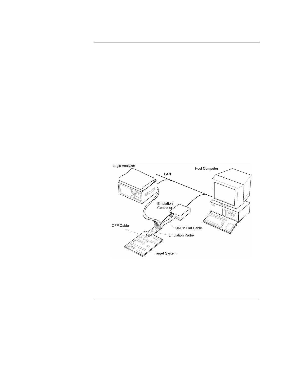
The HP E3472A/73A Emulator provides distributed emulation environment
for the Hitachi SH7040/50 Series processors. Depending on size and
requirements of your development, you can use it either as a simple emulator
working standalone, or as a powerful debugging environment by connecting
it to a logic analyzer.
Hooking up the HP E3472A/73A Emulator to an HP’s logic analyzer enables
high-speed real-time tracing. You can control the emulator and logic analyzer
through the HP E3755A/56A Debug User Interface, allowing you to operate
the emulation environment with a feel similar to conventional debuggers.
Figure 1-1. Distributed Emulation Environment wit h HP E3472A/73A
2
Page 18
Emulator Components
Emulation controller
Product Overview
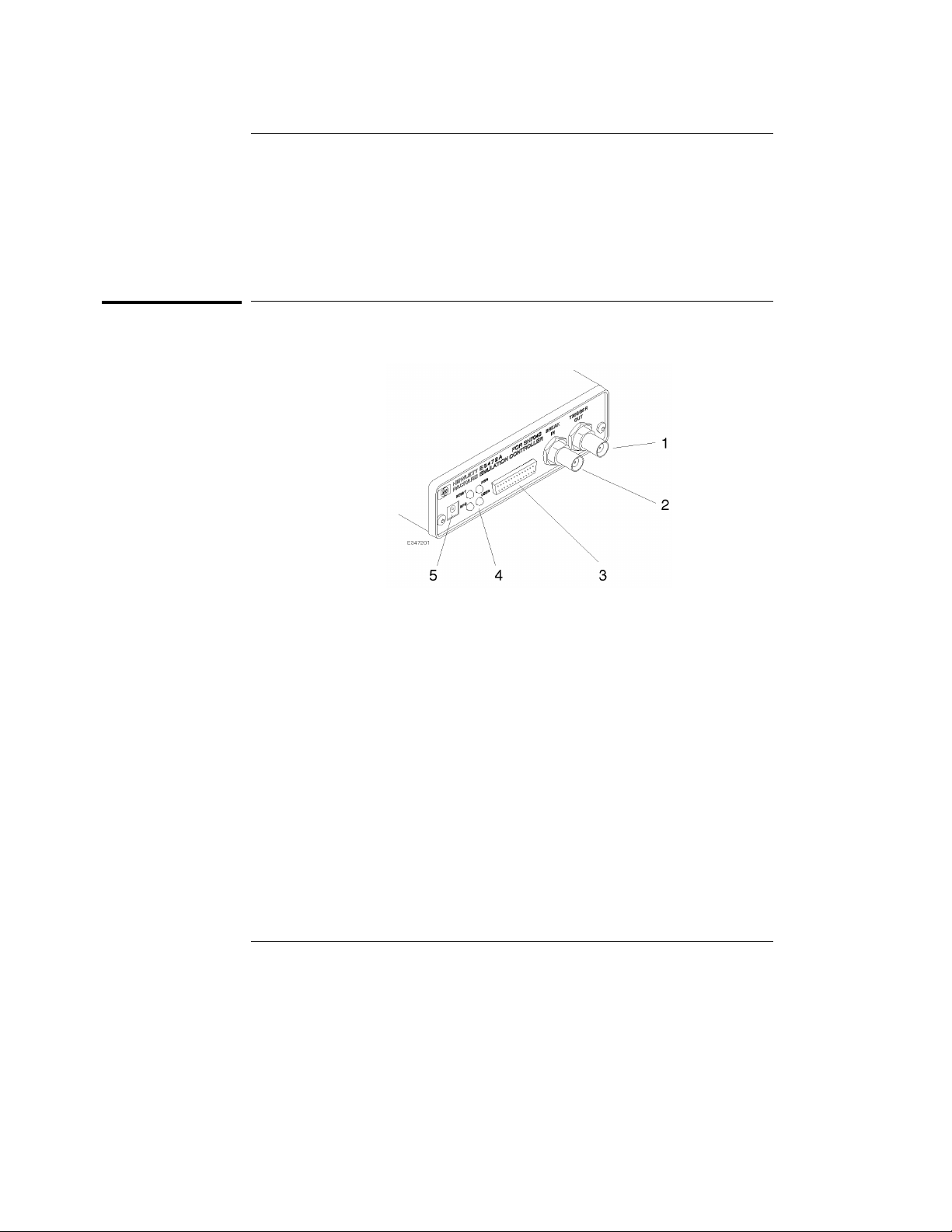
Emulation controller
1. TRIGGER OUT connector Sends out the trigger signal.
2. BREAK IN connector Receives the trigger signal from the logic
analyzer.
3. 50-pin connector Connected to the emulation probe through the
50-pin flat cable.
4. Status LEDs Indicate the operating status of the emulation
controller.
5. Auxiliary power connector Supplies power to the emulation probe.
3
Page 19
Product Overview
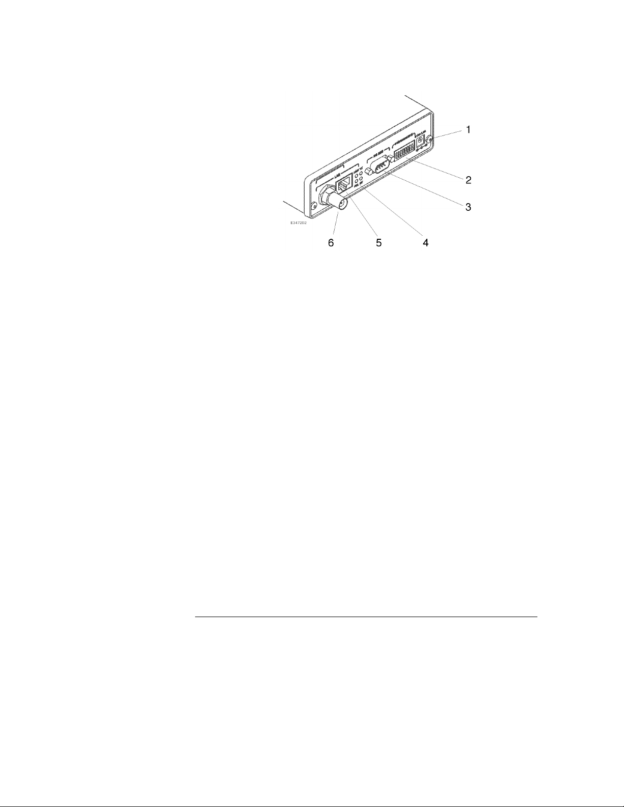
Emulation controller
1. Power connector Connects the power cable.
Connecting/disconnecting the power cable will
switch ON/OFF the emulator.
2. DIP switches Configure the settings of the Emulator.
Instructions are printed on the bottom of the
emulation controller.
3. RS-232 connector Connects the RS-232 cable to communicate with
the host computer via the serial connection.
4. LAN status LEDs Indicate the communication status of the
Emulator working on the LAN.
5. LAN connector (10BASE-T) Connects the LAN cable when the Emulator
communicates with the host computer via
10BASE-T LAN.
6. LAN connector (10BASE2) Connects the LAN cable when the Emulator
communicates with the host computer via
10BASE2 LAN.
4
Page 20
Product Overview
Emulation probe
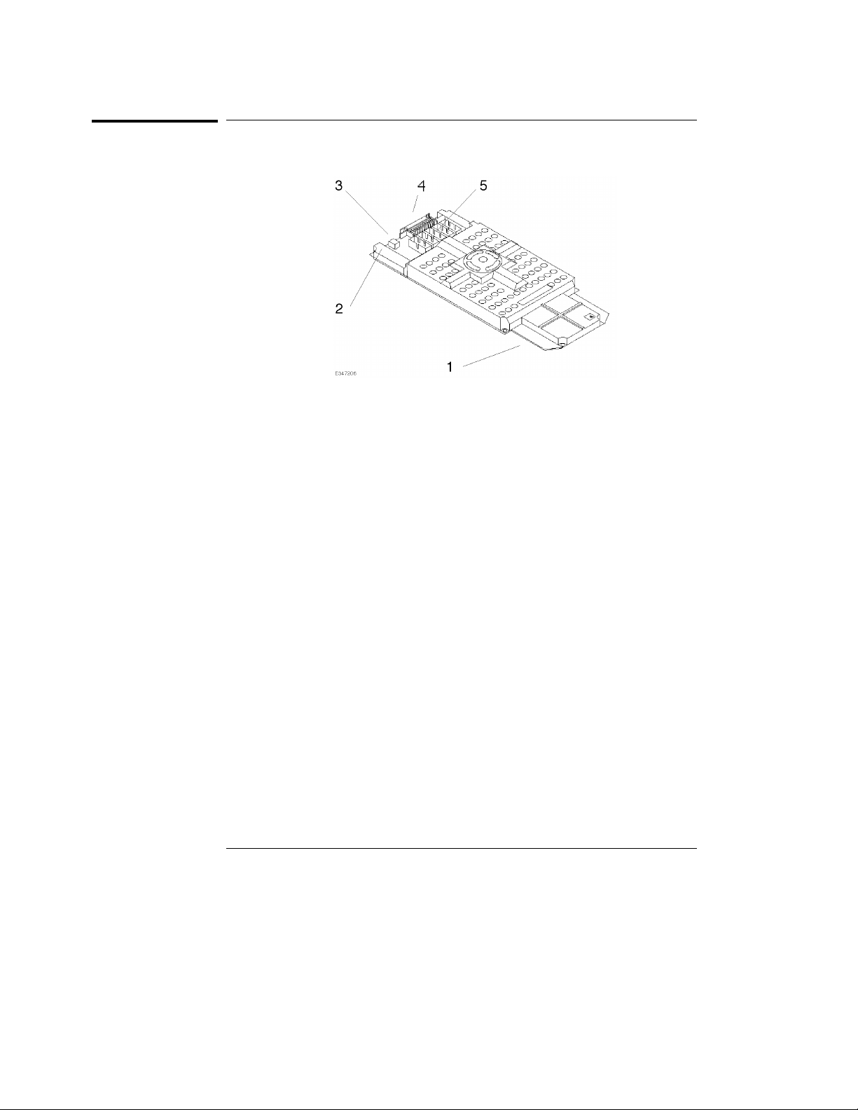
Emulation probe
1. PGA connector Connects to the QFP socket/adapter seated on
the target system.
2. Power LED Indicates that power is supplied to the emulation
probe.
3. Power connector Connects the auxiliary power cable from the
emulation controller.
4. 50-pin connector Connected to the emulation controller through
the 50-pin flat cable.
5. Pod connector Connects the pods of the logic analyzer.
5
Page 21

Product Overview
The target connection
Usage - Quick Guide
The target connection
The HP E3472A/73A Emulator connects to your target system via a flexible
cable. The cable plugs into a QFP socket/adapter on the target system.
The host computer connection
The HP E3472A/73A Emulator can communicate with a host computer via a
LAN connection (10 BASE-T or 10 BASE2).
The configuration switches
Use the DIP switches on the emulation controller to configure
communication to the host computer. There is a guide to these switches on
the bottom of the emulation controller.
The status LEDs
LEDs show the status of the power supply, the target system, and the
connection to the host computer.
6
Page 22

2
Contents of HP E3472A/73A
Contents of HP E3472A/73A
7
Page 23

Contents of HP E3472A/73A
Contents of HP E3472A/73A
This chapter provides you the information necessary for the
followings.
• Incoming Inspection
• Instruction for Cleaning
8
Page 24

Incoming Inspection
Contents of HP E3472A/73A
Incoming Inspection
WARNING
To avoid hazardous electrical shock, do not turn on the HP E3472A/73A
when there are signs of shipping damage to any portion of the outer
enclosure (for example, covers, or panel).
Inspect the shipping container for damage. If the shipping container of
cushioning material is damaged, it should be kept until the contents of the
shipment have been checked for completeness and the HP E3472A/73A
Processor Probe has been checked mechanically and electrically. The
contents of the shipment should be as listed in next page. If the contents are
incomplete, if there is mechanical damage or defect, or if the HP E3472A/73A
does not pass the performance verification test, notify the nearest
Hewlett-Packard office. If the shipping container is damaged, or the
cushioning materials shows signs of unusual stress, notify the carrier as well
as the Hewlett-Packard office. Keep the shipping materials for the carrier’s
inspection.
9
Page 25

Contents (HP E3472A)
Description Qty. HP Part Number
SH7040 emulation probe board 1 E3472-66501
Emulation probe top cover 1 E3472-04101
Emulation probe bottom cover 1 64783-04102
SH7040 demo board 1 E3472-66 502
Emulation controller 1 E3472-65001
50-pin flat cable 1 E3496-61601
AUX power cable 1 E3496-61 602
AC/DC adapt er 1 0 950-3043
Power cable 1 8120- 4753
3-wire to 2-wire adapter 1 5080-3149
Loop-back board 1 E3496-66502
Coaxial cable (120 cm) 1 8120-1840
Thin LAN T-connector 1 92227N
Thin LAN 50 ohm terminator (2 pcs) 1 92227 P
Plastic rivet kit 1 64748-68700
Others (including manuals)
Contents of HP E3472A/73A
Incoming Inspection
1
This cable is not suitable for LAN but for trigger input to the Emulator or performance
1
verification test. Do not use this as a LAN cable.
10
Page 26

Contents (HP E3473A)
Description Qty. HP Part Number
SH7050 emulation probe board 1 E3473-66501
Emulation probe top cover 1 E3472-04101
Emulation probe bottom cover 1 64783-04102
SH7050 demo board 1 E3473-66 502
Emulation controller 1 E3473-65001
50-pin flat cable 1 E3496-61601
AUX power cord 1 E3496-61 602
AC/DC adapt er 1 0 950-3043
Power cord 1 8120-4753
3-wire to 2-wire adapter 1 5080-3149
Loop-back board 1 E3496-66502
Coaxial cable (120 cm) 1 8120-1840
Thin LAN T-connector 1 92227N
Thin LAN 50 ohm terminator (2 pcs) 1 92227 P
Plastic rivet kit 1 64748-68700
Others (including manuals) 1
Contents of HP E3472A/73A
Incoming Inspection
1
This cable is not suitable for LAN but for trigger input to the Emulator or performance
1
verification test. Do not use this as a LAN cable.
11
Page 27

Contents of HP E3472A/73A
Instruction for Cleaning
Instruction for Cleaning
For cleaning the case and operation panel of the Emulation
Controller, wipe with soft cloth that is soaked with water and wrung
tightly, without undue pressure.
Ventilation Requirements
To ensure adequate ventilation, make sure that there is adequate
clearance around the emulation controller, the emulation probe, and
the AC/DC adapter.
12
Page 28

3
Setting up th e Emulator
Setting up the Emulator
13
Page 29

Setting up the Emulator
Setting up the Emulator
Caution To prevent the emulator and the target system from being damaged, be sure
to follow the cautions below when handling them.
• When connecting/disconnecting the emulation controller and
emulation probe, first disconnect the power cable from the
emulation controller to stop supplying power and then the
emulation probe from the target system.
• To prevent the emulator from being damaged by static electricity,
store and use the emulator in a place resistant to static electricity.
WARNING
• When supplying power to the emulator, check that the emulation
probe is plugged into the target system or demo board.
Before connecting the Emulator to the power supply, be sure to follow the
instructions below regarding the power cable.
The HP E3472A/73A Emulator is shipped from the factory with a power
supply and cord appropriate for your country. Use only the supplied HP
power supply and cord. Failure to use the proper power cable could result in
electric shock.
For protection from electrical shock, the power cable ground must not be
defeated.
The power plug must be plugged into an outlet that provides a protective
earth ground connection.
14
Page 30
Setting up th e Emulator
Procedure
Procedure
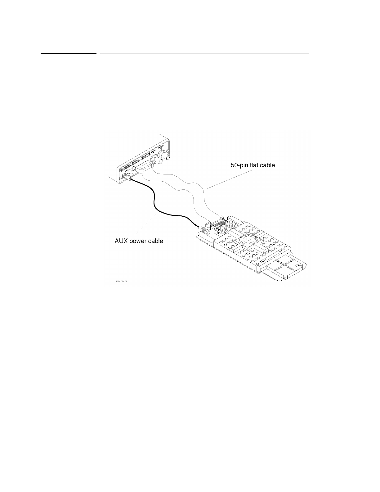
1 Connect the power supply cord between the emulation probe and
emulation controller.
2 Connect the 50-pin ribbon cable between the emulation probe and
the emulation controller.
3 Plug the emulation probe into the target system
Figure 3-1. Connecting the Emulation Controller and the Emulation Probe
15
Page 31

Setting up the Emulator
To connect the power cord and turn on the HP E3472A/73A Emulator
To connect the power cord and turn on the
HP E3472A/73A Emulator
The HP E3472A/73A Emulator does not have an On/Off switch. To turn the
HP E3472A/73A Emulator on or off, plug or unplug it from the power supply.
1
Plug the power cable into the adapter and outlet.
2 Connect the 5-V power cable to the receptacle in the rear panel of the
HP E3472A/73A Emulator.
Note The power lights on the emulation controller and the emulation probe are lit,
indicating the HP E3472A/73A Emulator is powered on. Note that the
Emulator does not have power switch.
16
Page 32

Note
Setting up th e Emulator
To test the HP E3472A/73A Emulator
To test the HP E3472A/73A Emulator
If this is the first time you have used the HP E3472A/73A Emulator, you
should run the built-in performance verification test before you connect to a
target system.
For details on the procedure of the performance verification test, see page
108.
Installing the Emulation Memory Module
There are three types of emulation memory modules that can be inserted into
sockets on the probe.
Installing the emulation memory requires the plastic rivet kit (HP Parts No.
64748-68700).
1
Remove plastic rivets that secure the plastic cover on the top of the
emulator probe, and remove the cover. The bottom cover is only
removed when you need to replace a defective active probe on the
exchange program.
2 Insert emulation memory module on the emulation probe. There is a
cutout on one side of the memory modules so that they can only be
installed one way.
To install memory modules, place the memory module into the socket groove
at an angle. Firmly press the memory module into the socket to make sure it
is completely seated. Once the memory module is seated in the connector
groove, pull the memory module forward so that the notches on the socket fit
17
Page 33

Setting up the Emulator
Installing the Emulation Memory Module
into the holes on the memory module. There are two latches on the sides of
the socket that hold the memory module in place.
3
Replace the plastic cover, and insert new plastic rivets to secure the
cover.
18
Page 34

4
Connecting to the Host Computer
Connecting to the Host
Computer
19
Page 35

Connecting to the Host Computer
Connecting to the Host Computer
To use the HP E3472A/73A Emulator you need to:
• Connect the HP E3472A/73A Emulator to the target system
(described in the next chapter)
• Connect the HP E3472A/73A Emulator to a power source. See
"Assembling the Emulator" for the connection procedure.
• Power on the target system
• Connect the HP E3472A/73A Emulator to the host computer via a
LAN
• Set up the host software
If you plan to use the HP E3472A/73A on a PC, you will need to set up
a serial connection to set the IP address for LAN.
As a debugger controlling the Emulator, you can use the
HP E3755A/56A Debug User Interface on a UNIX workstation or a PC.
Note When supplying power to the emulator, check that the emulation probe is
plugged into the target system or demo board.
20
Page 36

Connecting to the Host Computer
Setting Up a LAN Connection
The HP E3472A/73A Emulator has two LAN connectors:
• A BNC connector that can be directly connected to a IEEE 802.3
Type 10BASE2 cable (ThinLAN). When using this connector, the
HP E3472A/73A Emulator provides the functional equivalent of a
Medium Attachment Unit (MAU) for ThinLAN.
• An IEEE 802.3 Type 10BASE-T connector.
Use either the 10BASE2 or the 10BASE-T connector. Do not use both.
The HP E3472A/73A Emulator will not work with both connected at
the same time.
You must assign an IP address (Internet address) to the
HP E3472A/73A Emulator before it can operate on the LAN. You can
also set other network parameters such as a gateway address. The IP
address and other network parameters are stored in nonvolatile
memory within the HP E3472A/73A Emulator.
The HP E3472A/73A Emulator automatically sets a subnet mask
based on the subnet mask used by other devices on the network.
You can configure LAN parameters in any of the following ways:
• Using the built-in terminal interface. This is the most reliable
method.
• Using ipconfig700. The ipconfig700 program is supplied with the
HP E3755A/56A Debug User Interface on HP and Sun workstations.
• Using BOOTP. BOOTP is part of the HP-UX operating systems.
21
Page 37

Connecting to the Host Computer
To obtain a n IP address
To obtain an IP address
1 Obtain the following information from your local network
administrator or system administrator:
An IP address for the HP E3472A/73A Emulator.
•
The gateway address.
•
The gateway address is an IP address and is entered in integer dot notation.
The default gateway address is 0.0.0.0, which allows all connections on the
local network or subnet. If connections are to be made to workstations on
other networks or subnets, this address must be set to the address of the
gateway machine.
2
Find out whether port numbers 6470 and 6471 are already in use on
your network.
The host computer interfaces communicate with the HP E3472A/73A
Emulator through two TCP service ports. The default base port number is
6470. The second port has the next higher number (default 6471).
The default numbers (6470, 6471) can be changed if they conflict with some
other products on your network. TCP service port numbers must be greater
than 1024. If you change the base port, the new value must also be entered in
the /etc/services file on the host computer. For example, you could modify
the line:
hp64700 6470/tcp
To change the port numbers, see page 23. If you have already set the IP
address, you can use a telnet connection instead of a serial connection to
connect to the HP E3472A/73A Emulator.
Also you have to be sure that the port number you use does not conflict with
the one for the logic analyzer.
3
Write down the link-level address of the HP E3472A/73A Emulator.
You will need this address if you use BOOTP or ipconfig700 to set the IP
address.
The link-level address (LLA) is printed on a label above the LAN connectors
on the HP E3472A/73A Emulator. This address is configured in each
HP E3472A/73A Emulator shipped from the factory and cannot be changed.
22
Page 38

Connecting to the Host Computer
To configure LAN parameters using the built-in terminal interface
To configure LAN parameters using the built-in
terminal interface
1 Set configuration switches S1 through S4 to CLOSED, and set the
other switches as appropriate for your serial interface.
Switch settings are printed on the bottom of the HP E3472A/73A Emulator. If
you will use a baud rate of 9600 baud, set the switches like this:
2
Connect an ASCII terminal (or terminal emulator) to the
HP E3472A/73A Emulator’s RS-232 port with a 9-pin RS-232 cable.
Complete instructions for setting up a serial connection are described at
"Setting Up a Serial Connection" in this chapter.
3
Plug in the HP E3472A/73A Emulator’s power cord. Press the
terminal’s <RETURN> key a couple times. You should see a "R>",
"p>" or "c>" prompt.
At this point, you are communicating with the HP E3472A/73A Emulator’s
built-in terminal interface.
4
Display the current LAN configuration values by entering the lan
command:
R>lan
lan is disabled
lan -i 0.0.0.0
lan -g 0.0.0.0
lan -p 6470
Ethernet Address : 08000903212f
The "lan -i" line shows the current IP address (IP address) of the
HP E3472A/73A Emulator.
The "Ethernet Address", also known as the link-level address, is preassigned
at the factory, and is printed on a label above the LAN connectors.
5
Enter the following command:
lan -i <internet> [-g <gateway>] [-p <port>]
The lan command parameters are:
23
Page 39

Connecting to the Host Computer
To configure LAN parameters using the built-in terminal interface
-i <internet> The IP address which you obtained from your network administrator.
-g <gateway> The gateway address. Setting the gateway address allows access outside
your local network or subnet.
-p <port> This changes the base TCP service port number.
The default numbers (6470, 6471) can be changed if they conflict with some
other products on your network. TCP service port numbers must be greater
than 1024. If you change the base port, the new value must also be entered in
the /etc/services file on the host computer. For example, you could modify
the line:
hp64700 6470/tcp
6
Disconnect the power cord from the HP E3472A/73A Emulator, and
connect the the HP E3472A/73A Emulator to your network.
This connection can be made by using either the 10BASE-T connector or the
10BASE2 (BNC) connector on the HP E3472A/73A Emulator. Do not use
both connectors at the same time.
7
Set the configuration switches to indicate the type of connection that
is to be made.
Switch S1 must be set to OPEN, indicating that a LAN connection is being
made.
Switch S5 should be 1 if you are connecting to the BNC connector:
Switch S5 should be 0 if you are connecting to the 10BASE-T connector:
Set all other switches to CLOSED.
8
Connect the power cord to the HP E3472A/73A Emulator.
9 Verify your HP E3472A/73A Emulator is now active and on the
network. See "To verify LAN communications" in this chapter.
24
Page 40

Connecting to the Host Computer
To configure LAN parameters using the built-in terminal interface
Once you have set a valid IP address, you can use the telnet utility to connect
to the HP E3472A/73A Emulator, and use the lan command to change LAN
parameters.
Example
For example, to assign an IP address of 192.6.94.2 to the HP E3472A/73A
Emulator, enter the following command:
R>lan -i 192.6. 94.2
The IP address and any other LAN parameters you change are stored in
nonvolatile memory and will take effect the next time the HP E3472A/73A
Emulator is powered off and back on again.
See Also
"Solving Problems," page 103, if you have problems verifying LAN
communication.
25
Page 41

Connecting to the Host Computer
To configure LAN parameters using "ipconfig700"
To configure LAN parameters using "ipconfig700"
When you are using HP 9000/700 computer or Sun SPAPCsystem with HP
B3755A/56A installed in it, you can use ipconfig700 command to configure
LAN parameters.
The ipconfig700 command sets the IP address and gateway address for the
HP E3472A/73A Emulator. An IP address must be configured before a
network interface connection can be made.
The ipconfig700 command cannot be used if your workstation is running a
bootp daemon. If this is the case, use BOOTP to configure LAN parameters.
To determine if BOOTP is enabled on your computer, see "To configure LAN
parameters using BOOTP" in this chapter.
The following steps need to be taken when configuring the network
parameters with ipconfig700.
1
Connect the HP E3472A/73A Emulator to your network. This
connection can be made by using either the 10BASE-T connector or
the 10BASE2 BNC connector on the HP E3472A/73A Emulator.
2 Set the configuration switches to indicate the type of connection that
is to be made.
Switch S1 must be set to OPEN, indicating that a LAN connection is being
made. Switch S6 must bet set to OPEN, to allow programming of the LAN
parameters.
26
Page 42

Connecting to the Host Computer
To configure LAN parameters using "ipconfig700"
Switch S5 should be 1 if you are connecting to the BNC connector:
Switch S5 should be 0 if you are connecting to the 10BASE-T connector:
Set all other switches to CLOSED.
3
Turn ON power to the HP E3472A/73A Emulator.
4 Wait at least 20 seconds for the HP E3472A/73A Emulator to connect
to the LAN.
5 Become the root user on the system from which you wish to
configure the HP E3472A/73A Emulator.
6 Enter the following command:
ipconfig700 -l <link> -i <internet> [-g <gateway>]
The ipconfig700 parameters are:
-l <link> The link-level address. Enter any letters in the address in upper case.
-i <internet> The IP address.
-g <gateway> The gateway address.
If the ipconfig700 command is entered without any options, the program
interactively prompts for the necessary information.
Disconnect the power cable from the emulation controller. Set
7
switch S6 back to CLOSED and connect the power cable again.
8 Verify your HP E3472A/73A Emulator is now active and on the
network. See "To verify LAN communications" in this chapter.
27
Page 43

Connecting to the Host Computer
To configure LAN parameters using "ipconfig700"
Example
If the link-level address on your HP E3472A/73A Emulator read
08000F090F30, and your system administrator gave you the IP address
192.35.12.6, you could enter the following command:
$ ip co nf ig700 -l 08000F090B 30 -i 192.35.12.6 <RETURN>
Because no gateway address was entered, this value would default to 0.0.0.0.
When the IP address is successfully programmed, ipconfig700 will display the
HP E3472A/73A Emulator version information.
Limitations of ipconfig700
The ipconfig700 command generally will not work if:
• the workstation and the HP E3472A/73A Emulator are on different subnet s
OR
• a BOOTP daemon running elsewhere on your network is configured to
respond to the link-level address of the HP E34 72A/73A Emulator.
28
Page 44

Connecting to the Host Computer
To configure LAN parameters using BOOTP
To configure LAN parameters using BOOTP
This method is applicable only if your HP-UX workstation is already running
bootpd, the BOOTP daemon. The ipconfig700 command does the same thing
as BOOTP and is easier to use.
The BOOTP software is shipped with HP-UX version 8.0 or later.
1
Make sure that your host computer supports BOOTP.
If the following commands yield the results shown below, your machine
supports the BOOTP protocol.
$ grep bootp /etc/services
bootps 67/udp
bootpc 68/udp
$ grep bootp /etc/inetd.conf
bootps dgram udp wait root /etc/bootpd bootpd
If the commands did not yield the results shown, you must either add BOOTP
support to your workstation or use a different method to configure the
HP E3472A/73A Emulator LAN parameters.
2
Add an entry to the host BOOTP database file, /etc/bootptab. For
example:
# Global template for options common to all HP 64700
emulators.
# Gateway addresses can be specified differently if
# necessary.
hp64700.global:\
:gw=0.0.0.0:\
:vm=auto:\
:hn:\
:bs=auto:\
:ht=ether
# Specific emulator entry specifying hardware address
# (link-level address) and ip address.
hpprobe.div.hp.com:\
:tc=hp64700.global:\
:ha=080009090B0E:\
:ip=192.6.29.31
29
Page 45

Connecting to the Host Computer
To configure LAN parameters using BOOTP
In the example above, the "ha=080009090B0E" identifies the link-level
address of the HP E3472A/73A Emulator.
The "ip=192.6.29.31" specifies the IP address that is assigned to the
HP E3472A/73A Emulator.
The node name is "hpprobe.div.hp.com".
For additional information about using bootpd, refer to the HP-UX man pages.
3
Connect the HP E3472A/73A Emulator to your network.
This connection can be made by using either LAN connector on the
HP E3472A/73A Emulator.
4
Set the configuration switches to indicate the type of connection that
is to be made.
Switch S1 must be set to OPEN, indicating that a LAN connection is being
made.
Switch S6 must be set to OPEN to enable BOOTP mode.
Switch S5 should be set to CLOSED if you are connecting to the BNC
connector
30
Page 46

Connecting to the Host Computer
To configure LAN parameters using BOOTP
Switch S5 should be set to OPEN if you are connecting to the 10BASE-T
connector.
Set all other switches to CLOSED.
5
Connect the power cord to the HP E3472A/73A Emulator.
Verify that the power light stays on after 10 seconds.
The IP address will be stored in EEPROM.
6
Disconnect the power cable from the emulation controller. Set
switch S6 back to CLOSED and connect the power cable again.
Do this so that the HP E3472A/73A Emulator does not request its IP address
each time power is cycled. The IP address is stored in EEPROM, so BOOTP
does not need to be run again. Leaving this switch on will result in slower
performance, increased LAN traffic, and even failure to power up (if the
BOOTP server becomes inactive).
7
Verify your HP E3472A/73A Emulator is now active and on the
network. See "To verify LAN communications" in this chapter.
31
Page 47

Note
Connecting to the Host Computer
To set the 10BASE-T configuration switches
To set the 10BASE-T configuration switches
Set switches S7 and S8 to CLOSED unless one of the following conditions is
true:
• If the LAN cable exceeds the standard length, set switch S7 to OPEN.
The HP E3472A/73A Emulator has a switch-selectable, twisted-pair receiver
threshold. With switch S7 set to OPEN, the twisted-pair receiver threshold is
lowered by 4.5 dB. This should allow you to use cable lengths of up to about
200 meters. If you use a long cable, you should consult with your LAN
cabling installer to ensure that:
The device at the other end of the cable has long cable capability, and
•
The cable is high-grade, low-crosstalk cable with crosstalk attenuation
•
of greater than 27.5 dB.
When switch S7 is set to CLOSED, the LAN port operates at standard
10BASE-T levels. A maximum of 100 meters of UTP cable can be used.
• If your network doesn’t support LINK BEAT integrity checking or if
the HP E3472A/73A Emulator is connected to a non 10BASE-T
network set this switch to LINK BEAT OFF (0 or OPEN).
In normal mode (switch S8 set to CLOSED), a link integrity pulse is
transmitted every 15 milliseconds in the absence of transmitted data. It
expects to receive a similar pulse from the remote MAU. This is the standard
link integrity test for 10BASE-T networks. If your network doesn’t support
the LINK BEAT integrity checking or if the Emulator is used on a non
10BASE-T network set this switch to LINK BEAT OFF (OPEN).
Setting switch S8 to OPEN when Link Beat integrity checking is required by
your network will cause the remote MAU to disable communications.
32
Page 48

Connecting to the Host Computer
To verify LAN communications
To verify LAN communications
1 Verify your HP E3472A/73A Emulator is now active and on the
network by issuing a telnet to the IP address.
This connection will give you access to the HP E3472A/73A Emulator’s
built-in terminal interface.
2
To view the LAN parameters, enter the lan command at the terminal
interface prompt.
3 To exit from this telnet session, type <CTRL>D at the prompt.
The best way to change the HP E3472A/73A Emulator’s IP address, once it
has already been set, is to telnet to the HP E3472A/73A Emulator and use the
terminal interface lan command to make the change. Remember, after
making your changes, you must cycle power or enter a terminal interface
init -p command before the changes take effect. Doing this will break the
connection and end the telnet session.
If You Have Problems
If you encounter problems, refer to the "Solving Problems" chapter (page 99).
Example
$ telnet 192.35.1 2.6
R>lan
lan is enabled using TP
lan -i 192.35.12.6
lan -g 0.0.0.0
lan -p 6470
Subnet Mask: 255.255.255.0
Ethernet Address: 08000F090B30
33
Page 49

Connecting to the Host Computer
To verify LAN communications
Setting Up a Serial Connection
To set up a serial connection, you will need to:
• Set the serial configuration switches
• Connect the HP E3472A/73A Emulator to the RS-232 interface
• Connect a serial cable between the host computer and the
HP E3472A/73A Emulator
• Verify communications
Serial connections on a workstation
You should not use a serial connection on a workstation, except to set
LAN parameters.
Serial connections on a PC
You should not use a serial connection on a PC, except to set LAN
parameters or to update the HP E3472A/73A firmware.
34
Page 50

Connecting to the Host Computer
To set the serial configuration switches
To set the serial configuration switches
1 Set switch S1 to CLOSED (RS-232).
2 Set switches S2-S4 to CLOSED.
3 Set switch S5 to CLOSED (HW HANDSHAKE ON) if your serial
interface uses the DSR:CTS/RTS lines for flow control. Set S5 to
OPEN (HW HANDSHAKE OFF) if your serial interface uses software
flow control (XON/XOFF).
If your serial interface supports hardware handshaking, you should use it (set
switch S5 to CLOSED). Hardware handshaking will make the serial
connection much more reliable.
4
Set switches S6-S8 for the baud rate you will use. These switch
settings are listed on the bottom of the HP E3472A/73A Emulator.
The higher baud rates may not work reliably with all hosts and user
interfaces. Make sure the baud rate you choose is supported by your host
and user interface.
Example
To use a baud rate of 9600 baud, set the switches as follows:
35
Page 51

Caution
Connecting to the Host Computer
To connect a serial cable
To connect a serial cable
Connect an RS-232C modem cable from the host computer to the
HP E3472A/73A Emulator. The recommended cable is HP part number
C2932A. This is a 9-pin cable with one-to-one pin connections.
Use the recommended cable. If the cable is not shielded, or if the cable is not
grounded at the serial controller, the HP E3472A/73A Emulator may be
damaged by electrostatic discharge.
36
Page 52

Connecting to the Host Computer
To verify serial communications
To verify serial communications
1 Start a terminal emulator program on the host computer.
If you are using a PC, the Terminal application (HyperTerminal) in Microsoft
Windows 95 will work fine.
If you are using a UNIX workstation, you can use a terminal emulator such as
kermit.
2
Plug the power cord into the HP E3472A/73A Emulator.
When the HP E3472A/73A Emulator powers up, it sends a message (similar
to the one that follows) to the serial port and then displays a prompt:
Copyright (c) Hewlett-Packard Co. 1987
All Rights Reserved. Reproduction, adaptation, or translation without prior
written permission is prohibited, except as allowed under copyright laws.
HPE3499B Series Emulation System
Version: A.07.00 17Aug96
Location: Generics
HPE3472A Hitachi SH7040 Series Emulator
Version: A.00.00 17Aug96 17:07
Speed: 33.3 MHz
Memory: 0 KBytes
PC Board: f200-00e0-0000-78ff
R>
The version numbers may be different for your HP E3472A/73A Emulator.
3 Press the Return or Enter key a few times.
You should see a prompt such as "R>", "p>" or "c>".
See Also
"Problems with the Serial Interface" in Chapter 10.
37
Page 53

Connecting to the Host Computer
Note
Note
38
Page 54

5
Connecting to the Target System
Connecting to the Target
System
39
Page 55

Connecting to the Target System
Connecting to a Target System
Attach the QFP socket/adapter to the target system in advance.
The HP E3472A/73A Emulator is connected to the target system by
inserting the QFP cable attached to the emulation probe into the QFP
socket/adapter.
40
Page 56

Connecting to the Target System
QFP cable
QFP cable
Use one of the following QFP cables to connect the HP E3472A/73A
Emulator to the target system.
• 112-pin QFP cable (HP Part Number E3472B)
• 144-pin QFP cable (HP Part Number E3472C)
• 168-pin QFP cable (HP Part Number E3473B)
QFP socket/adapter
The cables listed above come with a socket/adapter required for connecting
to the target system.
When mounting and securing the processor to the target system, a socket
cover is necessary.
The 112-pin cable comes with a socket cover. For 144- and 168-pin cables,
you need to purchase it separately:
• 144-pin socket cover (HP Part Number E3472-61631)
• 168-pin socket cover (HP Part Number E3473-61630)
41
Page 57

Connecting to the Target System
Connecting the HP E3472A/73A Emulator to the target system
Connecting the HP E3472A/73A Emulator to the target
system
Caution
To prevent the emulator and the target system from being damaged, be sure
to follow the cautions below when handling them.
• Be sure to turn off the emulator and the target system before
connecting them.
• Check that the orientation of the QFP socket/adapter and the QFP
cable is correct.
• To prevent the emulator from being damaged by static electricity,
store and use the emulator in a place resistant to static electricity.
• Check that the ground line of the emulator and that of the target
system are properly connected.
• When turning the system on, switch on the target system first and
then the emulator. When turning the system off, switch off the
emulator first and then the target system.
• When supplying power to the emulator, check that the emulation
probe is plugged into the target system or demo board.
Caution Do not apply excessive force to the QFP cable. Doing so may damage the
cable.
42
Page 58

Connecting to the Target System
Connecting the HP E3472A/73A Emulator to the target system
1 Check that the emulator and the target system are OFF.
2 Remove the processor from the target system.
3 Connect the QFP cable to the emulation probe.
4 Connect the QFP cable so that pin 1 of the QFP cable is inserted into
pin 1 of the QFP socket/adapter on the target system (see Figure 5-1).
5 Switch on the target system; then switch on the emulator.
Figure 5-1. Connecting HP E3472A/73A Emulator into the Target System.
43
Page 59

Connecting to the Target System
Note
Note
44
Page 60

6
Designing a Target System
Designing a Target System
45
Page 61

Designing a Target System
Designing a Target System
This chapter will help you design a target system that will work with
the HP E3472A/73A Emulator and describe instructions for use of the
target system.
46
Page 62

Designing a Target System
QFP socket/adapter
QFP socket/adapter
The following list shows available QFP socket/adapters.
112 pins HP Part Number E3472-61620 (with socket cover)
144 pins HP Part Number E3472-61621
168 pins HP Part Number E3473-61620
To mount the QFP socket/adapter, solder it directly onto the target system
board.
To mount the 168-pin QFP socket/adapter, bore a 3.4-mmφ hole in the target
system board so that the hole is located at the center of the bottom of the
socket/adapter when mounted and make a 3-mm width pattern around the
hole (see the figure below).
47
Page 63

Designing a Target System
Pin relationship between 177-pi n connector and QFP socket/adapter
Pin relationship between 177-pin connector and QFP
socket/adapter
For pin assignment of the 177-pin connector for each of the 112-, 144-, and
168-pin QFP socket adapter, see Chapter 9 "Specifications and
Characteristics."
Target interface
For electrical characteristics of the interface with the target system, see
Chapter 9 "Specifications and Characteristics."
Cautions in designing target systems
You should remember the followings when designing target systems.
• For operating frequency and operating supply voltage:
Supported range for the processor operation is 4.0 to 33.3 MHz in
frequency and 5±0.25V in power. Processors that operate at 3.3 V
are not supported.
48
Page 64

7
Using the Logic Analyzer
Using the Logic Analyzer
49
Page 65

Using the Logic Analyzer
Using the Logic Analyzer
This chapter describes you how to connect the logic analyzer to your
emulator.
50
Page 66

Using the Logic Analyzer
Connecting the Logic Analyzer
Connecting the Logic Analyzer
Follow the steps below to connect the logic analyzer to the HP E3472A/73A
Emulator.
1
Disconnect the power source from the HP E3472A/73A Emulator
2 Switch off the target system.
3 Connect the logic analyzer to the host computer via a LAN.
Enter the Configuration Screen of the logic analyzer to specify LAN
parameters. See LAN User’s Guide that comes with the logic analyzer
for detail.
Note If you specified the IP address for the logic analyzer when you installed
HP B3755A/56A Debug User Interface, giving the same address will skip the
addressing operation when you start the Debugger.
4
Connect the pods via the termination adaptors into the emulation
probe.
Connect the appropriate pods into the emulation probe according to the label
("POD 1", "POD 2", ..., "POD 5") on it. See Figure 7-1 and Table 7-1 to find the
connection mapping for your logic analyzer.
Figure 7-1. Connecting the Pod
51
Page 67

Using the Logic Analyzer
Connecting the Logic Analyzer
Table 7-1 Corespondance Emulation Probe with Pod
Logic Analyzer
Note
HP 16550,
HP 1660/1,
HP 1671
Emulation
Probe
Be sure to use HP 01650-63203 for the termination adapters. None of the
•
others can be used.
Connect/disconnect the adapter with holding the connector side.
•
5 Connect the TRIGGER OUT terminal of the logic analyzer and the
POD 1 Pod 1 Master Pod 1 Pod 1
POD 2
POD 3 Pod 3 Slave Pod 1 Pod 5
POD 4 Pod 4 Slave Pod 2 Pod 6
POD 5
Pod 2 Master Pod 2 Pod 2
Pod 5 Slave Pod 3 Pod 7
HP 16554/5/6 HP 1670
BREAK IN terminal of the emulation controller.
52
Page 68

Using the Logic Analyzer
To verify the connection
To verify the connection
Follow the steps below to verify the connection.
1 Power on the target system.
2 Connect the power source into the HP E3472A/73A Emulator.
3 Start the Debugger.
Specify the IP address for the logic analyzer if necessary.
4 Use trace function to see tracing is properly performed with the logic
analyzer.
53
Page 69

Using the Logic Analyzer
Restrictions
Restrictions
Resource
When you use the logic analyzer with HP E3472A/73A Emulator, the
following resources are reserved for the Emulator upon the activation of the
trace function.
Pod s Pods listed in Table 7-2 are reserved for the Emulator. The rest
of the pods can be used for Analyzer2 (See the table below).
Table 7-2 Available Pods When Connected to the Emulator
Logic Analyzer
HP 16550,
HP 1661,
HP 1671
Not Available Pod 6 Pod 6 Expand Pod 4 Pod 8
Available for
Analyzer2
None Pod 7, Pod 8 Master Pod 3,
Trigger Terms Trigger terms are partly reserved for the trace
analyzer. The rest of the terms are available for Analyzer2, which can be
configured as a timing analyzer or a state analyzer.
HP 1660 HP 16554/5/6 HP 1670
Pod 3, Pod 4
Master Pod 4
54
Page 70

Using the Logic Analyzer
Restrictions
Trigger/Store Condition with the trace label "DATA" The data
bus between the Emulator and the logic analyzer is 32 bit in width. The
condition which determines the enable bits depends on the data bus
width of the accessed area and the access size of the instruction. See the
below.
8/16/32-bit data bus area Same as the processor
Built-in ROM 32-bit data bus area
Peripheral registers
and built-in RAM
Mnemonics in the Trace List Normally, trace list shows the
mnemonics for the instructions which were actually executed and does
not show mnemonics for such instructions that were fetched but not
executed.
However, mnemonics may not be displayed when the corresponding
instruction was actually executed, or vice versa.
This can be observed around the bottom of the trace list and when the store
condition is set.
32-bit data bus area (Long word access)
16-bit data bus area (Byte access and word
access)
55
Page 71

Using the Logic Analyzer
Note
Note
56
Page 72

8
Specifications and Characteristics
Specifications and
Characteristics
57
Page 73

Specifications and Characteristics
Specifications and Characteristics
This chapter provides specifications and characteristics of HP E3472A/73A
Emulator.
This chapter covers:
• Processor compatibility
• Supported logic analyzer
• Target system interface
• Electrical specification
58
Page 74

Specifications and Characteristics
Processor compa tibility
Processor compatibility
The HP E3472A/73A Emulator supports the following Hitachi SH Series
processors.
Table 8-1. Supported Processors (HP E3472A)
Processor Package
SH7040 112-pin QFP
SH7041 144-pin QFP
SH7042 112-pin QFP
SH7043 144-pin QFP
SH7044 112-pin QFP
SH7045 144-pin QFP
Note
SH7040 Series processors that operate at low voltage (3.3V) are not
supported.
Table 8-2. Supported Processors (HP E3473A)
Processor Package
SH7050 168-pin QFP
SH7051 168-pin QFP
59
Page 75

Specifications and Characteristics
Supported Logic Analyzers
Supported Logic Analyzers
Main frame
1
16500B/C+16550A 102-channel logic analyzer card
16500B/C+16554A 68-channel logic analyzer card x 2
16500B/C+16555A/D 68-channel logic analyzer card x 2
16500B/C+16556A/D 68-channel logic analyzer card x 2
Portable
1660C/CS 136/102-channel portable logic analyzer
1661C/CS 136/102-channel portable logic analyzer
2
2
1670A/D 136/102-channel portable logic analyzer
1671A/D 136/102-channel portable logic analyzer
1 For 16500, a LAN card (16500H/L) is necessary.
2
LAN option is necessary.
Note Five pieces of the termination adapter (HP 01650-63203) are required to
connect the HP E3472A/73A to the logic analyzer. You cannot use other
termination adapters.
60
Page 76

Specifications and Characteristics
Target System Requirements
Target System Requirements
Connection to the target systems that operate at the following voltage and
frequency is supported.
The HP E3472A Emulator
•
Operating voltage
Operating frequency 4.0 - 33.3 MHz
The HP E3473A Emulator
•
Operating voltage
Operating frequency 4.0 - 25.0 MHz
5±0.25 V
5±0.25 V
61
Page 77

Specifications and Characteristics
Target Interface (HP E3472A)
Target Interface (HP E3472A)
Vcc, Vss
/RES, NMI, MD0 - 3
PE13
PF, AVcc, AVref, AVss
62
Page 78

Specifications and Characteristics
Target Interface (HP E3472A)
EXTAL, XTAL
PLLVcc, PLLCAP, PLLVss
Others
Connect a circuit that meets the SH7040 Series
specification.
63
Page 79

Specifications and Characteristics
Target Interface (HP E3473A)
Target Interface (HP E3473A)
Vcc, Vss
/RES, /HSTBY, NMI, MD0 - 3
PC14
PH, AVcc+, +AVre, AVss
64
Page 80

Specifications and Characteristics
Target Interface (HP E3473A)
Vpp, EXTAL, XTAL
PLLVcc, PLLCAP, PLLVss
Others
Connect a circuit that meets the SH7050 Seriese
specification.
65
Page 81

Specifications and Characteristics
Target Interface (HP E3473A)
Table 8-3. E3472B PGA to QFP112 Adaptor Pin Assignment
PGA177
pin #
QFP112
pin #
Function
name
PGA177
pin #
QFP112
pin #
Function
name
1nc2449PA2
2nc25nc
3nc26nc
4 2 PE15 27 56 PD12
55 PC1 28 nc
6nc2957PD11
7 11 PC7 30 58 PD10
8nc31nc
9 17 PC13 32 60 PD8
10 21 Vcc 33 nc
11 nc 34 65 V
cc
12 nc 35 68 PD2
13 28 PB5 36 nc
14 nc 37 73 MD3
15 nc 38 77 V
cc
16 29 PB6 39 nc
17 31 PB8 40 80 PLLV
18 32 PB9 41 nc
19 35 WDTOVF 42 84 RES
20 nc 43 85 PE0
21 41 PA10 44 86 PE1
22 45 PA6 45 nc
23 nc 46 89 PE4
66
cc
Page 82

Specifications and Characteristics
Target Interface (HP E3473A)
Table 8-3. E3472B PGA to QFP112 Adaptor Pin Assignment
(Continued)
PGA177
pin #
QFP112
pin #
Function
name
PGA177
pin #
QFP112
pin #
47 nc 69 30 PB7
48 93 PF2 70 nc
49 96 PF5 71 33 V
50 nc 72 nc
51 nc 73 38 PA12
52 nc 74 42 PA9
53 104 PE6 75 nc
54 108 PE10 76 48 PA3
55 111 PE12 77 37 V
56 nc 78 52 PD15
57 1 PE14 79 54 PD13
58 nc 80 nc
59 3 V
ss
81 59 PD9
60 6 PC2 82 nc
Function
name
ss
cc
61 9 PC5 83 61 V
ss
62 12 PC8 84 63 PD6
63 15 PC11 85 66 PD4
64 18 PC14 86 69 PD1
65 22 PB1 87 nc
66 24 PB2 88 74 EXTAL
67 26 PB4 89 nc
68 nc 90 nc
67
Page 83

Specifications and Characteristics
Target Interface (HP E3473A)
Table 8-3. E3472B PGA to QFP112 Adaptor Pin Assignment
(Continued)
PGA177
pin #
QFP112
pin #
Function
name
PGA177
pin #
QFP112
pin #
91 81 PLLCAP 113 25 PB3
92 83 PA15 114 27 V
93 87 PE2 115 nc
94 88 PE3 116 34 PA14
95 nc 117 nc
96 90 V
ss
118 nc
97 94 PF3 119 43 PA8
98 97 AV
ss
120 46 PA5
99 nc 121 nc
100 101 V
ss
122 50 PA1
101 102 PE5 123 nc
102 105 PE7 124 55 V
103 109 V
ss
125 GND
104 112 PE13 126 62 PD7
Function
name
ss
ss
105 GND 127 nc
106 4 PC0 128 nc
107 7 PC3 129 nc
108 nc 130 71 V
ss
109 13 PC9 131 75 MD2
110 nc 132 nc
111 19 PC15 133 78 MD1
112 23 V
ss
134 82 PLLV
68
ss
Page 84

Specifications and Characteristics
Target Interface (HP E3473A)
Table 8-3. E3472B PGA to QFP112 Adaptor Pin Assignment
(Continued)
PGA177
pin #
QFP112
pin #
Function
name
PGA177
pin #
QFP112
Pin #
Function
135 nc 157 47 PA4
136 nc 158 39 V
137 91 PF0 159 51 PA0
138 95 PF4 160 53 PD14
139 98 PF6 161 nc
140 100 AV
cc
162 64 PD5
141 nc 163 67 PD3
142 nc 164 70 PD0
143 106 PE8 165 72 XTAL
144 110 PE11 166 76 NMI
145 GND 167 nc
146 8 PC4 168 79 MD0
147 10 PC6 169 nc
148 14 PC10 170 92 PF1
name
ss
149 16 PC12 171 nc
150 20 PB0 172 99 PF7
151 nc 173 nc
152 nc 174 Vnc
153 nc 175 103 V
cc
154 36 PA13 176 107 PE9
155 40 PA11 177 GND
156 44 PA7
69
Page 85

Specifications and Characteristics
Target Interface (HP E3473A)
Table 8-4. E3472C PGA to QFP144 Adaptor Pin Assignment
PGA177
pin #
QFP144
pin #
Function
name
PGA177
pin #
QFP144
pin #
Function
name
1nc2462PA21
2 1 PA23 25 66 PD21
33 PA22 26 nc
4 5 PE15 27 72 PD16
58 PC1 28 nc
6 12 Vcc 29 73 PD15
7 16 PC7 30 74 PD14
8nc3176PD12
9 22 PC13 32 78 PD11
10 26 Vcc 33 81 PD9
11 30 PA19 34 85 V
cc
12 nc 35 89 PD2
13 36 PB5 36 nc
14 nc 37 95 MD3
15 nc 38 99 V
cc
16 37 PB6 39 101 PA17
17 39 PB8 40 104 PLLVcc
18 41 PB9 41 nc
19 44 WDTOVF 42 108 RES
20 nc 43 109 PE0
21 50 PA10 44 110 PE1
22 54 PA6 45 112 V
cc
23 58 PA27 46 114 PE4
70
Page 86

Specifications and Characteristics
Target Interface (HP E3473A)
Table 8-4. E3472C PGA to QFP144 Adaptor Pin Assignment
(Continued)
PGA177
pin #
QFP144
pin #
Function
name
PGA177
pin #
QFP144
pin #
47 nc 69 38 PB7
48 120 PF2 70 40 V
49 123 PF5 71 42 V
50 nc 72 45 PD31
51 nc 73 48 PA12
52 132 PA2 74 51 PA9
53 136 PA5 75 55 V
54 140 PE10 76 59 PD26
55 143 PE12 77 63 V
56 nc2 78 67 PD20
57 2 PE14 79 70 PD17
58 4 PA21 80 nc
59 6 V
ss
81 75 PD13
60 9 PC2 82 77 V
Function
name
cc
ss
ss
cc
cc
61 13 PC5 83 79 V
ss
62 17 PC8 84 82 PD6
63 20 PC11 85 86 PD5
64 23 PC14 86 90 PD2
65 27 PB1 87 nc
66 31 PB2 88 96 EXTAL
67 34 PB4 89 100 PA16
68 nc 90 nc
71
Page 87

Specifications and Characteristics
Target Interface (HP E3473A)
Table 8-4. E3472C PGA to QFP144 Adaptor Pin Assignment
(Continued)
PGA177
pin #
QFP144
pin #
Function
name
PGA177
pin #
QFP144
pin #
Function
91 105 PLLCAP 113 32 PB3
92 107 PA15 114 35 V
93 111 PE2 115 nc
94 113 PE3 116 43 PA14
95 115 PE5 117 46 PD30
96 117 V
ss
118 nc
97 121 PF3 119 52 PA8
98 124 AV
ss
120 56 PA5
99 nc 121 60 PD25
100 129 V
ss
122 64 PD23
101 133 PA3 123 68 PD19
102 137 PE7 124 71 V
103 141 V
ss
125 GND
104 144 PE13 126 80 PD10
name
ss
ss
105 GND 127 83 PD7
106 7 PC0 128 87 V
ss
107 10 PC3 129 91 PD1
108 14 V
ss
130 93 V
ss
109 18 PC9 131 97 MD2
110 nc 132 nc
111 24 PC15 133 102 MD1
112 28 V
ss
134 106 PLLV
72
ss
Page 88

Specifications and Characteristics
Target Interface (HP E3473A)
Table 8-4. E3472C PGA to QFP144 Adaptor Pin Assignment
(Continued)
PGA177
pin #
QFP144
pin #
Function
name
PGA177
pin #
QFP144
pin #
Function
135 nc 157 57 PA28
136 116 PE6 158 61 V
137 118 PF0 159 65 PD22
138 122 PF4 160 69 PD18
139 125 PF6 161 GND
140 127 AV
cc
162 84 PD6
141 130 PA0 163 88 PD4
142 134 PA4 164 92 PD0
143 138 PE8 165 94 XTAL
144 142 PE11 166 98 NMI
145 GND 167 nc
146 11 PC4 168 103 MD0
147 15 PC6 169 nc
148 19 PC10 170 119 PF1
name
ss
149 21 PC12 171 nc
150 25 PB0 172 126 PF7
151 29 PA20 173 128 AV
cc
152 33 PA18 174 131 PA1
153 nc 175 135 V
cc
154 47 PA13 176 139 PE9
155 49 PA11 177 GND
156 53 PA7
73
Page 89

Specifications and Characteristics
Target Interface (HP E3473A)
Table 8-5. E3473B PGA to QFP168 Adaptor Pin Assignment
PGA177
pin #
QFP168
pin #
Function
name
PGA177
pin #
QFP168
pin #
Function
name
11 PG9 2471 PE4
2 2 PG10 25 75 PE7
3 4 PG12 26 79 V
cc
4 6 PG14 27 82 PE12
59 PB0 2884 PE14
6 13 Vcc 29 85 PD0
7 17 PA0 30 86 PD1
8 21 Vcc 31 88 PD3
9 25 PA6 32 90 PD4
10 29 Vcc 33 93 PD6
11 33 PA12 34 97 V
cc
12 37 Vcc 35 101 PD12
13 40 PB7 36 105 V
cc
14 42 PB9 37 109 MD3
15 43 PB10 38 113 V
cc
16 44 PB11 39 117 PF3
17 46 PC1 40 121 PLLV
18 48 PC2 41 124 HSTBY
19 51 WDTOVF 42 126 RES
20 55 V
cc
43 127 PF4
21 59 PC9 44 128 PF5
22 63 PC13 45 130 V
cc
23 67 PE1 46 132 PF8
74
cc
Page 90

Specifications and Characteristics
Target Interface (HP E3473A)
Table 8-5. E3473B PGA to QFP168 Adaptor Pin Assignment
(Continued)
PGA177
pin #
QFP168
pin #
Function
name
PGA177
pin #
QFP168
pin #
47 135 PF11 69 45 PC0
48 139 PH2 70 47 V
49 143 PH5 71 49 V
50 147 PH8 72 52 PC4
51 151 PH10 73 56 PC7
52 155 PH13 74 60 PC10
53 159 PG0 75 64 V
54 163 PG4 76 68 PE2
55 166 PG6 77 72 V
56 168 PG8 78 76 PE8
57 3 PG11 79 80 PE11
58 5 PG13 80 83 PE13
59 7 V
ss
81 87 PD2
60 10 PB1 82 89 V
Function
name
cc
ss
ss
cc
cc
61 14 PB4 83 91 V
ss
62 18 PA1 84 94 PD7
63 22 PA4 85 98 PD10
64 26 PA7 86 102 PD13
65 30 PA10 87 106 PF0
66 34 PA13 88 110 EXTAL
67 38 PB6 89 114 PF1
68 41 PB8 90 118 V
pp
75
Page 91

Specifications and Characteristics
Target Interface (HP E3473A)
Table 8-5. E3473B PGA to QFP168 Adaptor Pin Assignment
(Continued)
PGA177
pin #
QFP168
pin #
Function
name
PGA177
pin #
QFP168
pin #
Function
91 122 PLLCAP 113 35 PA14
92 125 CK 114 39 V
93 129 PF6 115 nc
94 131 PF7 116 50 PC3
95 133 PF9 117 53 PC5
96 136 V
ss
118 57 V
97 140 PH3 119 61 PC11
98 144 AV
ss
120 65 PC14
99 148 PH9 121 69 PE3
100 152 AV
ss
122 73 PE5
101 156 PH14 123 77 PE9
102 160 PG1 124 81 V
103 164 V
ss
125 GND
104 167 PG7 126 92 PD5
name
ss
ss
ss
105 GND 127 95 PD8
106 8 PG15 128 99 V
ss
107 11 PB2 129 103 PD14
108 15 V
ss
130 107 V
ss
109 19 PA2 131 111 MD2
110 23 V
ss
132 115 V
ss
111 27 PA8 133 119 MD1
112 31 V
ss
134 123 PLLV
76
ss
Page 92

Specifications and Characteristics
Target Interface (HP E3473A)
Table 8-5. E3473B PGA to QFP168 Adaptor Pin Assignment
(Continued)
PGA177
pin #
QFP168
pin #
Function
name
PGA177
pin #
QFP168
pin #
Function
125 nc 157 66 PE0
136 134 PF10 158 70 V
137 137 PH0 159 74 PE6
138 141 PH4 160 78 PE10
139 145 PH6 161 GND
140 149 AV
ref
162 96 PD9
141 153 PH11 163 100 PD11
142 157 PH15 164 104 PD15
143 161 PG2 165 108 XTAL
144 165 PG5 166 112 NMI
145 GND 167 116 PF2
146 12 PB3 168 120 MD0
147 16 PB5 169 nc
148 20 PA3 170 138 PH1
name
ss
149 24 PA5 171 142 AV
cc
150 28 PA9 172 146 PH7
151 32 PA11 173 150 AV
cc
152 36 PA15 174 154 PH12
153 nc 175 158 V
cc
154 54 PC6 176 162 PG3
155 58 PC8 177 GND
156 62 PC12
77
Page 93

Specifications and Characteristics
Target Interface (HP E3473A)
Figure 8-1. Pin Locations of the 177-pin Connector
78
Page 94

Specifications and Characteristics
Electrical Specifications
Electrical Specifications
BNC, labeled TRIGGER OUT
Output Drive Logic high level >= 2.0 V when occurring monitor
program with 50-ohm load or when in reset. Logic low level <= 0.4 V
when running user code with 50-ohm load.
BNC, labeled TRIGGER IN
Input Edge-triggered TTL level input (positive high), 20 pf, with 2K
ohms to ground in parallel. Maximum input: 5 V above V
ground.
Communications
Seria l Port 9-pin female type “D” subminiature connector. RS-232
DCE to 115.2 kbaud.
10BASE-T LAN Port RJ-45 connector. IEEE 802.3 10BASE-T
(StarLAN).
5 V below
CC;
10BASE2 LAN Port 50-ohm BNC connector. IEEE 802.3 10BASE2
(ThinLAN). When using this connector, the HP E3472A/73A Emulator
provides the functional equivalent of a Medium Attachment Unit (MAU)
for ThinLAN.
Power Supply
Input 100-240Vac, 1.0Amax, 50/60Hz.
Output 12Vdc, 3.3A
79
Page 95

Specifications and Characteristics
Electrical Specificat ions
Table 8-6. Clock Timing (E3472A)
Characteristic Symbol SH7040 Typical
min max min max min max
(*1)
Worst Case Unit
Operating frequency f
Clock cycle time t
Clock low-pulse width t
Clock high-pulse width t
Clock rise time t
Clock fall time t
EXTAL input frequency t
EXTAL input cycle time t
EXTAL input low-level pulse width t
EXTAL input high-level pulse width t
EXTAL input rise time t
EXTAL input fall time t
Reset Oscillation setting time t
Software standby oscillation setting time t
*1 Typical outputs measured with 50pF load
op
cyc
CL
CH
cr
cf
EX
Excyc
EXL
EXH
EXR
EXF
OSC1
OSC2
4 28.7 4 33.3 4 33.3 MHz
34.8 250 30 250 30 250 ns
10-13- 7 - ns
10-15- 7 - ns
-5-4-8 ns
-5-3-8 ns
410410410MHz
100 250 100 250 100 250 ns
40-40-40- ns
40-40-40- ns
-5-5-5 ns
-5-5-5 ns
10-10-10- ms
10-10-10- ms
80
Page 96

Specifications and Characteristics
Table 8-7. Control Signal Timing (E3472A)
Characteristic Symbol SH7040 Typical
min max min max min max
Electrical Specifications
(*1)
Worst Case Unit
RES rise time t
RES fall time t
RESET pulse width t
MRESET pulse width t
NMI rise time t
NMI fall time t
RES setup time t
MRES setup time t
NMI setup time t
IRQ0 - IRQ7 setup time
(edge detection time)
IRQ0 - IRQ7 setup time
(level detection time)
NMI hold time t
IRQ0 - IRQ7 hold time t
IRQOUT output delay time t
Bus request setup time t
Bus acknowledge delay time 1 t
Bus acknowledge delay time 2 t
Bus 3-state delay time t
*1 Typical outputs measured with 50pF load
RESr
RESf
RESW
MRESW
NMIr
NMIf
RESS
MRESS
NMIS
t
IRQES
t
IRQLS
NMIH
IRQEH
IRQOD
BRQS
BACD1
BACD2
BZD
-200 -200 ns
-200 -200 ns
20 - 20 - t
20 - 20 - t
cyc
cyc
-200 -200 ns
-200 -200 ns
35 - 85 - ns
35 - 45 - ns
35 - 95 - ns
35 - 45 - ns
35 - 45 - ns
35 - 35 - ns
35 - 35 - ns
-35 -40 ns
35 - 45 - ns
-35 -40 ns
-35 -40 ns
-35 -40 ns
81
Page 97

Specifications and Characteristics
Electrical Specificat ions
Table 8-8. Bus Timing (E3472A)
Characteristic Symbol SH7040 Typical
min max min max min max
(*1)
Worst Case Unit
Address delay time t
CS delay time 1 t
CS delay time 2 t
Read strobe delay time 1 t
Read strobe delay time 2 t
Read data setup time t
Read data hold time t
Write strobe delay time 1 t
Write strobe delay time 2 t
Write data delay time t
Write data hold time t
Wait setup time t
Wait hold time t
RAS delay time 1 t
RAS delay time 2 t
CAS delay time 1 t
CAS delay time 2 t
Read data access time t
RD to read data access time t
Column address to read data access
time
AD
CSD1
CSD2
RSD1
RSD2
RDS
RDH
WSD1
WSD2
WDD
WDH
WTS
WTH
RASD1
RASD2
CASD1
CASD2
ACC
OE
t
AA
(2) 18 - 9 - 23 ns
(2)21 - 11-26ns
(2) 21 - 8 - 26 ns
(2) 18 - 9 - 23 ns
(2) 18 - 7 - 23 ns
(15) - 15 - 25 - ns
0- 0 -0-ns
(2)18 - 11-23ns
(2) 18 - 8 - 23 ns
-35 - 14-40ns
0(10) 4 --5-ns
15 - 15 - 25 - ns
0- 0 -0-ns
(2)18 - 10-23ns
(2) 18 - 7 - 23 ns
(2) 18 - 8 - 23 ns
(2) 18 - 6 - 23 ns
39.6 - 39.6 - 29.6 - ns
22.2 - 22.2 - 12.2 - ns
39.6 - 39.6 - 29.6 - ns
RAS to read data access time t
CAS to read data access time t
Low address hold time t
Low address setup time t
*1 Typical outputs measured with 50pF load
82
RAC
CAC
RAH
ASR
57 - 57 - 47 - ns
4.8 - 4.8 - -5.2 - ns
2.4- 12 --2.6- ns
-.1 - 12 --5.1- ns
Page 98

Specifications and Characteristics
Table 8-8. Bus Timing (E3472A)
(Continued)
Characteristic Symbol SH7040 Typical
min max min max min max
Electrical Specifications
(*1)
Worst Case Unit
Data input setup time t
Data input hold time t
Write address setup time t
Write address hold time t
Write data hold time t
RDWR delay time 1 t
RDWR delay time 2 t
High-speed page mode
CAS
precharge time
RAS precharge time t
CAS setup time t
AH delay time 1 t
AH delay time 2 t
Multiplexed address delay time t
Multiplexed address hold time t
DACK0-DACK1 delay time 1 t
*1 Typical outputs measured with 50pF load
DS
DH
AS
WR
WRH
RWD1
RWD2
t
CP
RP
CSR
AHD1
AHD2
MAD
MAH
DACKD1
-7.6 - 8 - -12.6 - ns
20 - 50 - 15 - ns
0 - 14 --5-ns
5- 14 -0-ns
0- 7 --5-ns
(2) 18 - 9 - 23 ns
(2) 18 - 7 - 23 ns
9.8 - 35 - 6.8 - ns
37.2 - 52 - 34.2 - ns
10 - 49 - 5 - ns
(2)18 - 10-23ns
(2)18 - 10-23ns
(2)18 - 14-23ns
0 - 18 --5-ns
(2) 21 (omitted) - 26 ns
83
Page 99

Specifications and Characteristics
Electrical Specifications
Table 8-9. DMAC Timing (E3472A)
Characteristic Symbol SH7040 Typical
min max min max min max
(*1)
Worst Case Unit
DREQ0 DREQ1
setup time
DREQ0 DREQ1
hold time
DREQ0 DREQ1
pulse width
DRAK output delay time t
*1 Typical outputs measured with 50pF load
DRAKD
t
DRQS
t
DRQH
t
DRQW
18 - 28 -
18 - 18 -
1.5 - 1.5 -
-18 -23ns
84
Page 100

Specifications and Characteristics
Table 8-9. Clock Timing (E3473A)
Characteristic Symbol SH7050 Typical
min max min max min max
Electrical Specifications
(*1)
Worst Case Unit
Operating frequency f
Clock cycle time t
Clock low-pulse width t
Clock high-pulse width t
Clock rise time t
Clock fall time t
EXTAL input frequency t
EXTAL input cycle time t
EXTAL input low-level pulse width t
EXTAL input high-level pulse width t
EXTAL input rise time t
EXTAL input fall time t
Reset Oscillation setting time t
Software standby oscillation setting time t
*1 Typical outputs measured with 50pF load
op
cyc
CL
CH
cr
cf
EX
Excyc
EXL
EXH
EXR
EXF
OSC1
OSC2
TBD 20 4 25 TBD 25 MHz
50 TBD 50 250 50 TBD ns
20-19-17- ns
20-24-17- ns
-5-3-8 ns
-5-2-8 ns
TBD 10 4 10 TBD 10 MHz
100 TBD 100 250 100 TBD ns
TBD - 40 - TBD - ns
TBD - 40 - TBD - ns
-TBD- 5 -TBD ns
-TBD- 5 -TBD ns
10-10-10- ms
10-10-10- ms
85
 Loading...