

Page 1
HPE 1820 Switch Series Quick Start
Guide
The switch drawings in this document are for illustration only and may not match your particular switch
model.
For more detailed instructions and information to set up your switch, view or download the Installation
and Getting Started Guide for your switch at http://www.hpe.com/support/hpesc.
1. Unpack and check included parts.
2. Prepare for installation. To avoid personal injury or product damage, review the “Safety Precautions” (page 5)
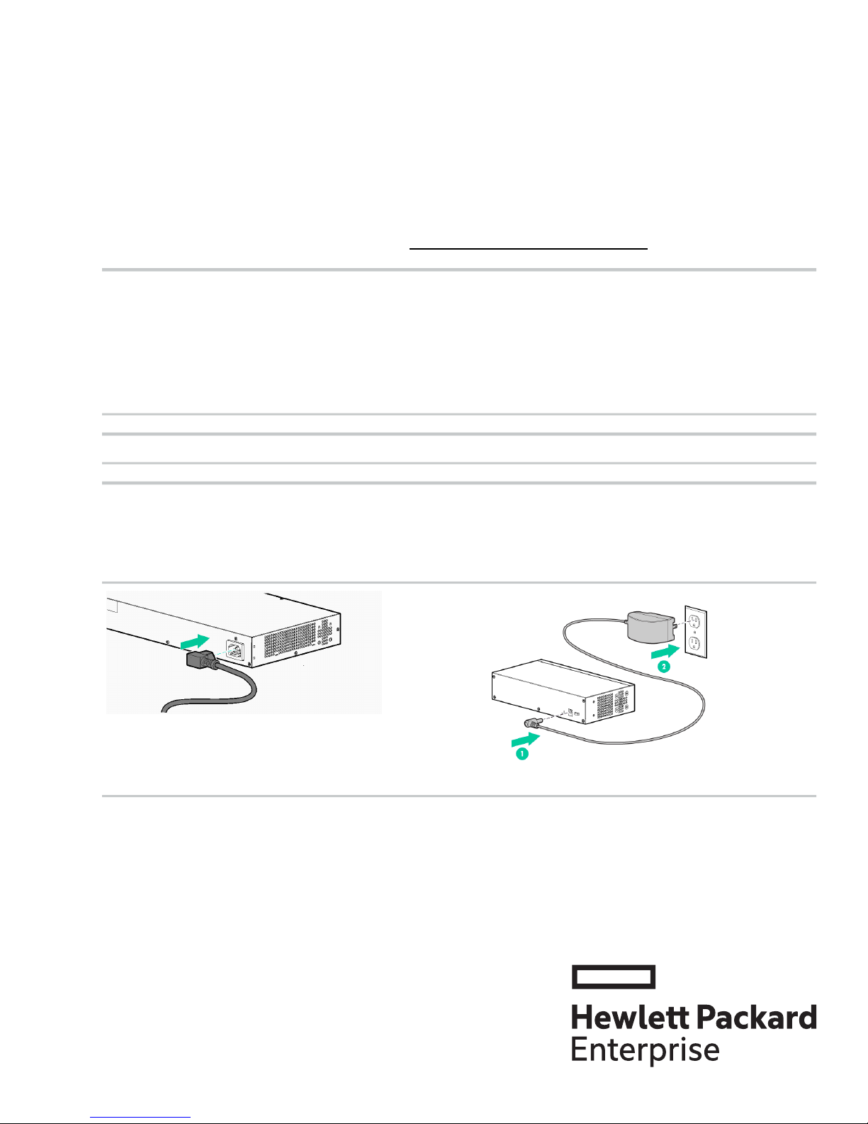
3. Power on and verify that Self-Test completes normally. For the 1820-24G, 1820-24G-POE+, 1820-48G, and
1820-48G-POE+ switches, connect the power cord to the power connector at the back of the switch, and then into an
electrical outlet.
For the 1820-8G and 1820-8G-POE+ switches, connect the AC/DC adapter power cord to the power connector at the back
of the switch, and then plug the AC/DC power adapter into an electrical outlet.
• Documentation kit
• Switch
• Accessory kit (installation hardware)
• AC power cord for HPE 1820-24G, 1820-24G-POE+,
1820-48G and 1820-48G-POE switch models or DC external
power adapter for 1820-8G and 1820-8G-POE+ switch
models
*5900-4819*
© Copyright 2014, 2016 Hewlett Packard Enterprise Development LP
The information in this document is subject to change without notice.
Part Number: 5900-4819
Published: January 2016
Page 2
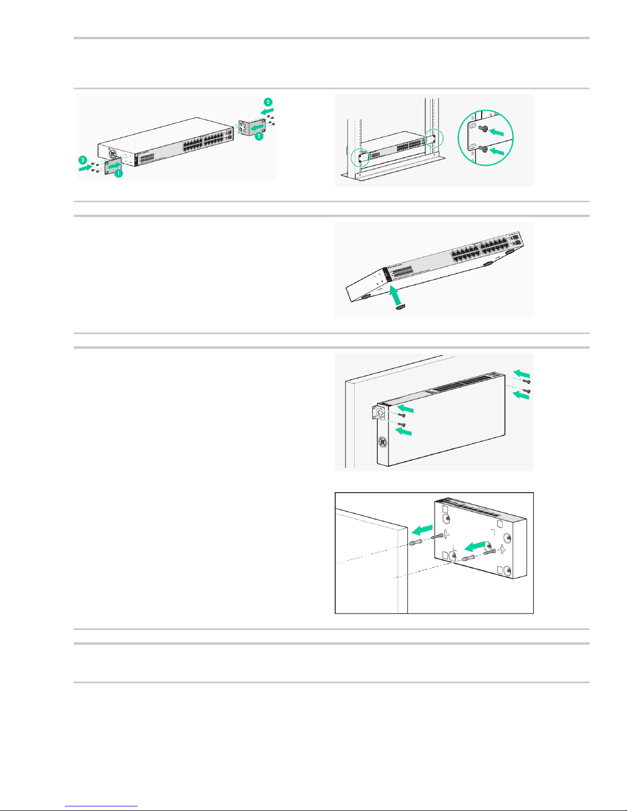
4. Mount the switch. Unplug the AC or DC power from the switch before mounting it.
Rack Mounting: Use a #1 Phillips (cross-head) screwdriver to attach the accessory kit brackets to the switch using the
eight 8-mm M4 screws. Then use the four number 12-24 screws to secure the brackets to the rack.
Table or Desktop Mounting: Attach the four self-adhesive
pads (included in the accessory kit) to the bottom corners of
the switch.
Wall or Under-table Mounting: To mount the 1820-24G,
1820-24G-POE+, 1820-48G, and 1820-48G-POE+ switches,
Use a #1 Phillips (cross-head) screwdriver and attach the
mounting brackets to the switch with the included 8-mm M4
screws. Attach the switch to the wall or wood surface with two
5/8-inch number 12 wood screws (not included).
To mount the 1820-8G and 1820-8G-POE+ switches, mark the
position for the mounting screws. The hole-to-hole distance is
3.54 inch (90-mm). Use a #1 Phillips (cross-head) screwdriver
and two of the included 20-mm 4 tap screws. Set the screw
heads approximately 2 mm away from the mounting surface to
allow the switch to slide on to the screws. Wall anchors are
included in the accessory kit for use with plastered brick or
concrete walls.
For under-table mounting, a third 20-mm M4 tap screw can be
placed against one side of the switch to secure it in place.
IMPORTANT: Wall-mount the switch with network ports
facing up or down (away from or toward the floor). Do not
wall-mount the switch with the ventilation holes facing up or
down. (See “Installation Precautions” (page 5))
5. Power on the switch.
Follow the same procedures as in step 3.
Page 3
6. Configure the switch for operation on your network
(minimal configuration).
Using a standard Ethernet cable, connect a PC directly to
the switch.
Before you connect the switch to the network, configure the
PC’s IP Address and Subnet Mask to allow it to communicate
with the switch through your PC’s Web browser.
Switch factory-default settings:
Factory Default SettingParameter
<blank>Password
192.168.1.1IP address
255.255.255.0Subnet Mask
not setDefault gateway
Modify the switch’s IP configuration to operate in your
network. See “Example: Initial Switch Configuration”
(page 3)
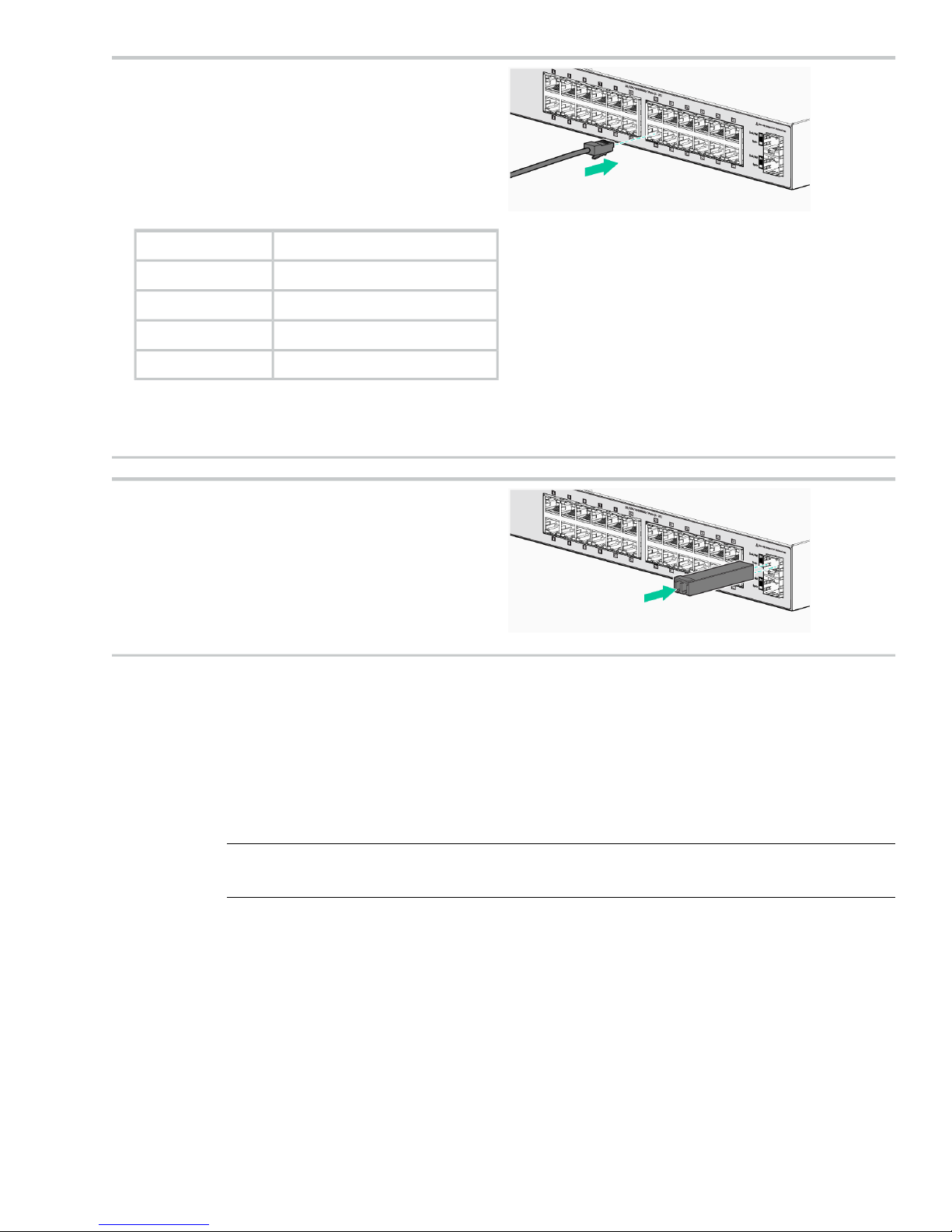
7. Connect the network cables.
NOTE: Fir transceiver connections, install and use only
HPE Mini-GBIC/SFP transceivers supported by the switch.
See “Mini-GBIS/SFP Installation Notes” (page 4).
Example: Initial Switch Configuration
1. Reconfigure the PC’s IP address and Subnet Mask so that it can communicate with the switch.
a. Click Start > Control Panel. Type adapter in the search box, and then click View network
connections
b. Select and right-click Local Area Connection, then click Properties.
c. Click the Networking tab. Select Internet Protocol Version 4 (TCP/IPv4) under This connection
uses the following items, and then click Properties.
NOTE: Be sure to record all your PC’s current IP settings to be able to restore them
later.
d. On the General tab, click Use the following IP address.
e. For IP address, enter an IP address in the same range as the switch’s default IP address. For
example, enter 192.168.1.12.
f. For Subnet mask, enter 255.255.255.0, then click OK.
g. Click Close (or OK) to close the Local Area Connection Properties screen.
2. Open your Web browser on the PC, and enter the switch factory-default address, http://192.168.1.1,
to access the switch’s Web interface.
3. Click Log on to log on to the switch (by default, there is no password).
4. Click Network Setup > Get Connected and configure IP network settings on the switch for operation
on your network.
Page 4

IMPORTANT: When the switch starts, it attempts to obtain an IP address from a DHCP
server. If the DHCP server is unreachable, the switch falls back to a static IP address, that is,
192.168.1.1. If a DHCP address is obtained then you must determine the IP address assigned
to the switch. To determine the IP address, access your DHCP server files or use LLDP (Link
Layer Discovery Protocol) commands on a connected device (such as another switch). For
more information on Initial Configuration, see Installation and Getting Started Guide available
at http://www.hpe.com/support/manuals.
5. Click Apply on the browser configuration screen to save your settings to retain them when the switch
is rebooted.
You are done with initial switch configuration. Disconnect the LAN cable from your PC and connect the
switch in to the network.
Be sure to return your PC to its original network settings before connecting to your network.
Mini-GBIS/SFP Installation Notes
NOTE: Use only genuine HPE Mini-GBIC/SFP transceivers supported by your switch.
When selecting a fiber SFP device, make sure it can function at a temperature that is not less than
the recommended maximum operational temperature of the product. Use only an approved Laser
Class 1 SFP transceiver.
Use only genuine HPE Mini-GBIC/SFPs. Non-HPE Mini-GBIC/SFP transceivers are not supported. Use
of genuine Hewlett Packard Enterprise products ensures that your network maintains optimal performance
and reliability. Should you require additional transceivers, please contact a Hewlett Packard Enterprise
sales representative or an authorized reseller.
Hot Swapping Mini-GBIC/SFP transceivers. Supported mini-GBIC/SFP transceivers that you can install
in your Hewlett Packard Enterprise switch can be “hot swapped”– removed and installed while the switch
is receiving power. You should disconnect the network cables from the mini-GBIC/SFP transceivers before
hot-swapping them, though.
When you replace a mini-GBIC/SFP transceiver with another of a different type, the switch may retain
selected port-specific configuration settings that were configured for the replaced unit. Be sure to validate
or reconfigure port settings as required.
Mini-GBIC/SFP Connections to Devices with Fixed Speed/Duplex Configurations. When connecting
a device to your switch port that contains a mini-GBIC/SFP transceiver, the speed and duplex settings of
the switch port and the connected device must match; otherwise, the device may not link properly—you
may not get a link. For some older network devices, including some older Hewlett Packard Enterprise
devices, the default speed/duplex settings may be predefined (for example, to 1000 Mbps/Full Duplex),
or otherwise set differently from the default configuration of your switch port. Because of these default
speed/duplex considerations, you should make sure that devices connected to your mini-GBIC/SFP ports
are properly configured. At a minimum, make sure the configurations match.
Page 5

Safety Precautions
Installation Precautions
WARNING!
• The rack or cabinet should be adequately secured to prevent it from becoming unstable, tilting
or falling.
Devices installed in a rack or cabinet should be mounted as low as possible, with the heaviest
devices at the bottom and progressively lighter devices above.
• Do not wall-mount any switch without checking for restrictions in the Installation and Getting
Started Guide.
Wall-mount the switch with network ports facing up or down (away from or toward the floor).
Do not wall-mount the switch with the ventilation holes facing up or down.
CAUTION:
• Ensure the power source circuits are properly grounded, then use the power cord supplied with
the switch to connect to the AC power source.
• If your installation requires a different power cord than the one supplied with the switch and/or
power supply, be sure the cord is adequately sized for the switch’s current requirements. In
addition, be sure to use a power cord displaying the mark of the safety agency that defines the
regulations for power cords in your country/region. The mark is your assurance that the power
cord can be used safely with the switch and power supply.
• When installing the switch, the AC outlet should be near the switch and should be easily
accessible in case the switch must be powered off.
• Ensure the switch does not overload the power circuits, wiring, and over-current protection. To
determine the possibility of overloading the supply circuits, add together the ampere ratings of
all devices installed on the same circuit as the switch and compare the total with the rating limit
for the circuit. The maximum ampere ratings are usually printed on the devices near the AC
power connectors.
• Do not install the switch in an environment where the operating ambient temperature exceeds
its specification.
• Ensure the air flow around the switch is not restricted. Leave at least 7.6 cm (3 inches) for
cooling.
Regulatory and Safety Information
For important safety, environmental, and regulatory information, see Safety and Compliance Information
for Server, Storage, Power, Networking, and Rack Products, available at http://www.hpe.com/support/
Safety-Compliance-EnterpriseProducts.
Page 6

1820 Switch Series Information — Regulatory and Safety
Electrical:
AC voltage:
current:
range:
Environmental:
1820-8G
Switch
(J9979A)
For power,
requires one of
the following:
External
•
power
adapter
module.
• or, PoE PD
connections
to Port 1
1820-24G
Switch
(J9980A)
For power,
requires a
power cord
connection from
an AC power
source
100-127 /
200-240
1820-48G
Switch (J9981A)
For power,
requires a power
cord connection
from an AC
power source
100-127 /
200-240
1820 1820-8G, 1820-24G 1820-48G, 1820-8G-PoE+ (65W),
1820-24G-PoE+ (185W), 1820-48G-PoE+ (370W) Switches
0°C to 40°C (32°F to 104°F)Operating Temperature:
15% to 95% at 40°C (104°F), non-condensingRelative humidity:
1820-8G-PoE+
(65W) Switch
(J9982A)
For power,
external power
adapter module
is required.
1820-24G-PoE+
(185W) Switch
(J9983A)
For power,
requires a
power cord
connection from
an AC power
source
100-127 /
200-240
1820-48G-PoE+
(370W) Switch
(J9984A)
For power,
requires a power
cord connection
from an AC
power source
100-127 /
200-240
5.1 / 2.6 A2.6 / 1.3 A0.8 / 0.5 A0.5 / 0.3 AMaximum
50/60 Hz50/60 Hz50/60 Hz50/60 HzFrequency
-40°C to 70°C (-40°F to 158°F)Non-Operating Temperature:
15% to 90% at 65°C (149°F), non-condensingNon-Operating Relative humidity:
Up to 3 km (10,000 ft)Maximum Operating Altitude:
The operating maximum altitude should not exceed that of any accessory
being connected to the switch.
Acoustic
1820-8G Switch, 1820-8G-PoE+ (65W) Switch, 1820-24G Switch, and
1820-48G Switch have no fan, 0 dB
1820-24G-PoE+ (185W) Switch and 1820-48G-PoE+ (370W) Switch
have fans, 45 dB
CSA22.2 No. 60950-1; EN60950-1/IEC60950-1; UL60950-1Safety
EN 60825-1 / IEC 60825-1 Class 1; Class 1 Laser Products / Laser
Klasse 1
NOTE: Use only supported genuine HPE Mini-GBIC/SFP transceivers with your switch.
When selecting a fiber SFP device, make sure it can function at a temperature that is not less than
the recommended maximum operational temperature of the product. Use only an approved Laser
Class 1 SFP transceiver.
1820-8G External Power Adapter and Power Cords:
(5066-11221) specifications:
• AC Input Voltage: 100–240 V
• Maximum AC Input Current: 0.4 A
AC power cord:Universal inline power adapter
Australia/New Zealand8121-0870
Thailand8121-0664
Page 7

• AC Input Frequency Range: 50/60 Hz
• DC Output Voltage: 12 ± 10% V
• Maximum DC Output Power: 15 W
• Maximum DC Output Current: 1.25 A
specifications:
• AC Input Voltage: 100–240 V
• Maximum AC Input Current: 0.4 A
• AC Input Frequency Range: 50/60 Hz
• DC Output Voltage: 12 ± 10% V
• Maximum DC Output Power: 13 W
• Maximum DC Output Current: 1.085
A
1
Complies with Energy Star 5.0 standards.
China8120-8373
India8121-0702
Israel8120-6314
Japan8120-6316
South Africa8120-6317
South Korea8120-6314
Taiwan8121-0702
United Kingdom/Hong Kong/8120-8699
Singapore/Malaysia
Brazil8121-1081
Argentina8121-8367
Chile8121-0514
(AC power cords are not used)Power adapter:Wall plug-in power adapter
1
1
United States/Canada/Mexico5184-5863
Continental Europe/Denmark/Norway/5184-5864
Sweden/Switzerland/Israel/
Vietnam/Indonesia
1820-8G-PoE+ External Power Adapter and Power Cords:
AC power cord:Universal inline power adapter
(5066-1122 PA21) specifications:
• AC Input Voltage: 100–240 V
• Maximum AC Input Current: 1.4 A
• AC Input Frequency Range: 50/60 Hz
• DC Output Voltage: 54+/- 1.5 V
• Maximum DC Output Power: 90 W
• Maximum DC Output Current: 1.67 A
Australia/New Zealand8121-0834
China8120-8377
Continental Europe8120-6082
Denmark8121-6086
India8121-0780
Israel8121-1035
Japan8120-6804
South Africa8121-0919
South Korea8120-6811
Switzerland8120-6807
Taiwan8121-0964
Thailand8121-0673
United Kingdom/Hong Kong/8120-6809
Singapore/Malaysia
Page 8

1
Complies with Energy Star 5.0 standards (as do the other adapters).
1820-24G, 1820-24G-PoE+, 1820-48G Power Cords
AC power cord:
Australia/New Zealand8121-0834
China8120-8377
Continental Europe8120-6082
Denmark8121-6086
India8121-0780
Israel8121-1035
Japan8120-6804
South Africa8121-0919
United States/Canada/Mexico8120-6805
Brazil8121-1069
Argentina8120-6869
Chile8120-6980
1820-48G-PoE+ Power Cords
AC power cord:
South Korea8120-6811
Switzerland8120-6807
Taiwan8121-0964
Thailand8121-0673
United Kingdom/Hong Kong/Singapore/Malaysia8120-6809
United States/Canada/Mexico8120-6805
Brazil8121-1069
Argentina8120-6869
Chile8120-6980
Australia/New Zealand8121-0857
China8121-1034
Continental Europe8120-5336
Denmark8120-5340
India8120-5341
Israel8121-1009
Japan8120-5342
South Africa8120-5341
South Korea8120-5336
Page 9

AC power cord:
Switzerland8120-5339
Taiwan8121-0967
Thailand8121-0671
United Kingdom/Hong Kong/Singapore/Malaysia8120-5334
United States/Canada/Mexico8121-0973
Brazil8121-1132
Argentina8120-8375
Chile8120-8389
1820-8G Switch (J9979A), 1820-24G Switch (J9980A), 1820-48G Switch (J9981A), 1820-8G-PoE+ (65W) Switch (J9982A),
1820-24G-PoE+ (185W) Switch (J9983A), 1820-48G-PoE+ (370W) Switch (J9984A)
Russia/Belarus/Kazakhstan/CEE Safety:
China Altitude Warning:
Japan Power Cord Warning:
Documentation feedback
Hewlett Packard Enterprise is committed to providing documentation that meets your needs. To help us
improve the documentation, send any errors, suggestions, or comments to Documentation Feedback
(docsfeedback@hpe.com). When submitting your feedback, include the document title, part number,
edition, and publication date located on the front cover of the document. For online help content, include
the product name, product version, help edition, and publication date located on the legal notices page.
 Loading...