

Page 1

AlphaServer DS20L
User’s Guide
Order Number: EK-DS20L-UG. B01
This manual is for managers and operators of HP AlphaServer
DS20L (Series EA2014) systems.
Hewlett-Packard Company
Page 2

May 2002
© 2002 Compaq Computer Corporation.
Compaq, the Compaq logo, Compaq Insight Manager, AlphaServer, Hewlett-Packard, HP, the
Hewlett-Packard logo, StorageWorks, and TruCluster Registered in U.S. Patent and Trademark Office.
Tru64 is a trademark of Compaq Information Technologies Group, L.P. in the United States and other
countries.
Linux is a registered trademark of Linus Torvalds in several countries. UNIX is a trademark of The
Open Group in the United States and other countries. All other product names mentioned herein may
be trademarks of their respective companies.
Compaq shall not be liable for technical or editorial errors or omissions contained herein. The
information in this document is provided “as is” without warranty of any kind and is subject to change
without notice. The warranties for Compaq products are set forth in the express limited warranty
statements accompanying such products. Nothing herein should be construed as constituting an
additional warranty.
FCC Notice
This equipment generates, uses, and may emit radio frequency energy. The equipment has been type
tested and found to comply with the limits for a Class A digital device pursuant to Part 15 of FCC
rules, which are designed to provide reasonable protection against such radio frequency interference.
Operation of this equipment in a residential area may cause interference in which case the user at his
own expense will be required to take whatever measures may be required to correct the interference.
Any modifications to this device—unless expressly approved by the manufacturer—can void the
user’s authority to operate this equipment under part 15 of the FCC rules.
Modifications
The FCC requires the user to be notified that any changes or modifications made to this device that are
not expressly approved by Compaq Computer Corporation may void the user's authority to operate the
equipment.
Cables
Connections to this device must be made with shielded cables with metallic RFI/EMI connector hoods
in order to maintain compliance with FCC Rules and Regulations.
Taiwanese Notice
Page 3

Japanese Notice
Canadian Notice
This Class A digital apparatus meets all requirements of the Canadian Interference-Causing Equipment
Regulations.
Avis Canadien
Cet appareil numérique de la classe A respecte toutes les exigences du Règlement sur le matériel
brouilleur du Canada.
European Union Notice
Products with the CE Marking comply with both the EMC Directive (89/336/EEC) and the Low
Voltage Directive (73/23/EEC) issued by the Commission of the European Community.
Compliance with these directives implies conformity to the following European Norms (in brackets are
the equivalent international standards):
EN55022 (CISPR 22) - Electromagnetic Interference
EN50082-1 (IEC801-2, IEC801-3, IEC801-4) - Electromagnetic Immunity
EN60950 (IEC950) - Product Safety
Warning!
This is a Class A product. In a domestic environment this product may cause radio interference in
which case the user may be required to take adequate measures.
Achtung!
Dieses ist ein Gerät der Funkstörgrenzwertklasse A. In Wohnbereichen können bei Betrieb dieses
Gerätes Rundfunkstörungen auftreten, in welchen Fällen der Benutzer für entsprechende
Gegenmaßnahmen verantwortlich ist.
Attention!
Ceci est un produit de Classe A. Dans un environnement domestique, ce produit risque de créer des
interférences radioélectriques, il appartiendra alors à l'utilisateur de prendre les mesures spécifiques
appropriées.
Page 4

Page 5

Contents
Preface ........................................................................................................................xi
Chapter 1 Overview
1.1 System Features and Components........................................................1-1
1.1.1 Features................................................................................................ 1-1
1.1.2 Components...........................................................................................1-4
1.2 Specifications ........................................................................................ 1-4
1.2.1 Power Connectors.................................................................................. 1-4
1.2.2 Estimated Power Consumption.............................................................1-5
1.2.3 Environmental...................................................................................... 1-6
1.2.3.1 Safety.............................................................................................. 1-7
1.2.3.2 EMC................................................................................................ 1-7
1.2.3.3 Thermal........................................................................................... 1-8
1.2.4 Physical................................................................................................. 1-8
1.2.4.1 I/O ................................................................................................... 1-8
1.2.5 Acoustical.............................................................................................. 1-9
1.3 Front Panel Controls and Indicators .................................................. 1-10
1.3.1 Removing the Front Bezel................................................................... 1-11
1.3.2 Inserting or Ejecting a CD.................................................................. 1-11
1.3.3 Halt Button......................................................................................... 1-12
1.4 Rear Panel Ports, Slots, and Indicators.............................................. 1-13
1.5 Internal View of the System ............................................................... 1-14
Chapter 2 Installation and Options
2.1 System Setup and Installation.............................................................. 2-1
2.1.1 Rackmounting....................................................................................... 2-2
2.1.2 Connecting the System ......................................................................... 2-2
2.2 Installing Options .................................................................................2-3
2.2.1 Bezel Removal....................................................................................... 2-3
2.3 Removal from a Rack............................................................................ 2-4
2.3.1 Removing the Cover.............................................................................. 2-5
2.3.2 Memory ................................................................................................. 2-6
v
Page 6

2.3.2.1
2.3.3 PCI Options........................................................................................... 2-8
2.3.4 Hard Drive ............................................................................................2-9
2.3.5 CD-ROM.............................................................................................. 2-14
Memory Configuration Rules..........................................................2-6
Chapter 3 Operation
3.1 Powering Up the System....................................................................... 3-1
3.1.1 Turning the System On......................................................................... 3-1
3.1.1.1 LEDs............................................................................................... 3-1
3.1.2 SROM Code........................................................................................... 3-1
3.1.4 Alpha SRM Console...............................................................................3-2
3.1.5 Power-Up Display .................................................................................3-3
3.2 Operating Systems................................................................................ 3-4
3.2.1 Setting Boot Options............................................................................. 3-4
3.2.1.1 auto_action...................................................................................... 3-5
3.2.1.2 bootdef_dev ..................................................................................... 3-6
3.2.1.3 boot_file........................................................................................... 3-7
3.2.1.4 boot_osflags..................................................................................... 3-8
3.2.1.5 ei*0_inet_init or ew*0_inet_init.................................................... 3-10
3.2.1.6 ei*0_protocols or ew*0_protocols .................................................. 3-11
3.2.2 Booting Tru64 UNIX........................................................................... 3-12
3.2.2.1 Booting from a Local Disk.............................................................3-12
3.2.2.2 Booting from a Remote Disk......................................................... 3-14
3.2.3 Starting a Tru64 UNIX Installation ................................................... 3-16
3.2.3.1 NHD4 and IPK Compatibility....................................................... 3-16
3.2.4 Installing and Booting Linux.............................................................. 3-18
3.3 Updating Firmware............................................................................. 3-21
3.3.1 Updating Firmware from a Network Device....................................... 3-23
3.3.2 LFU Commands.................................................................................. 3-25
Chapter 4 Remote Management
4.1 Overview ...............................................................................................4-1
4.2 Basic Remote Control............................................................................ 4-2
4.2.1 Startup.................................................................................................. 4-2
4.2.2 Shutdown .............................................................................................. 4-3
4.2.3 Link Status............................................................................................4-3
4.3 The WOL Utility ...................................................................................4-3
4.3.1 Operation ..............................................................................................4-4
4.3.2 Restrictions ........................................................................................... 4-5
4.3.3 Commands.............................................................................................4-5
vi
Page 7

Exit Status............................................................................................ 4-5
4.3.4
4.3.5 Error Conditions ...................................................................................4-5
4.3.6 Examples............................................................................................... 4-6
4.3.7 Environment Variables......................................................................... 4-7
Chapter 5 Basic Troubleshooting
5.1 LED Error Indicators............................................................................ 5-1
5.1.1 Internal Power Failure..........................................................................5-3
5.2 Halting the System ............................................................................... 5-3
5.3 Firmware Configuration Jumpers ........................................................ 5-4
5.3.1 J2 Firmware Configuration Jumper Block........................................... 5-5
5.4 Fan Status Display ...............................................................................5-6
Appendix A SRM Console
A.1 SRM Console Overview.........................................................................A-1
A.1.1 How Does SRM Boot an OS?.................................................................A-2
A.1.2 Loading the Secondary Bootstrap Loader.............................................A-2
A.2 Invoking the SRM Console....................................................................A-3
A.3 Command Summary .............................................................................A-4
A.3.1 Commands: Syntax ..............................................................................A-6
A.3.2 Commands: Special Keystrokes and Characters .................................A-7
A.4 Show Commands...................................................................................A-9
A.4.1 Show Config ..........................................................................................A-9
A.4.2 Show Device ........................................................................................A-11
A.4.3 Show hwrpb.........................................................................................A-13
A.4.4 Show IDE............................................................................................A-18
A.4.5 Show Memory......................................................................................A-19
A.4.6 Show PAL............................................................................................A-19
A.4.7 Show Power.........................................................................................A-20
A.4.8 Show Version.......................................................................................A-22
A.5 Creating a Power-Up Script................................................................A-23
A.6 Booting the Operating System............................................................A-25
A.7 Configuring a PCI NVRAM Module....................................................A-27
A.8 Testing the System..............................................................................A-28
A.9 Set Commands....................................................................................A-30
A.9.1 Set Password.......................................................................................A-30
A.9.2 Set Secure............................................................................................A-31
A.10 Secure Mode........................................................................................A-32
A.10.1 Login Command and Secure Mode ...............................................A-32
A.11 Clear Password ...................................................................................A-33
vii
Page 8

Resetting the Password ................................................................A-34
A.11.1
A.12 Stopping and Starting CPU................................................................A-34
A.13 Updating Firmware.............................................................................A-35
A.14 Forcing a System Crash Dump...........................................................A-36
A.15 Using Environment Variables.............................................................A-37
A.15.1 set envar........................................................................................A-37
A.15.2 show envar....................................................................................A-38
A.16 Depositing and Examining Data.........................................................A-39
A.17 Reading a File.....................................................................................A-42
A.18 Initializing the System........................................................................A-43
A.19 Finding Help .......................................................................................A-44
A.20 Environment Variable Summary........................................................A-45
A.20.1 ac_action .......................................................................................A-47
A.20.2 auto_action....................................................................................A-47
A.20.3 bootdef_dev ...................................................................................A-48
A.20.4 boot_osflags...................................................................................A-48
A.20.5 com1_baud ....................................................................................A-49
A.20.6 ew*0_mode....................................................................................A-50
A.20.7 ew*0_protocols..............................................................................A-50
A.20.8 os_type..........................................................................................A-51
A.20.9 password .......................................................................................A-51
A.20.10 pci_parity ......................................................................................A-52
A.20.11 pk*0_fast.......................................................................................A-52
A.20.12 pk*0_host_id.................................................................................A-53
A.20.14 sysvar............................................................................................A-54
A.20.15 tt_allow_login................................................................................A-54
A.20.16 wol_enable.....................................................................................A-55
Examples
3–1 Power-Up Display - Serial Console .......................................................3-3
3–2 Booting Tru64 UNIX from a Local Disk.............................................. 3-12
3–3 Booting Tru64 UNIX from a Remote Disk.......................................... 3-14
3–4 Text-Based Installation Display ......................................................... 3-16
3–5 Linux Boot Output .............................................................................. 3-19
3–6 Starting LFU from the SRM Console.................................................. 3-21
3–7 Updating Firmware from a Network Device....................................... 3-23
3–8 Updating Firmware Using a MOP Server .......................................... 3-23
5–1 Fan Statuses Using the SRM Show Power Command.......................... 5-7
A–1 Show Config Command.........................................................................A-9
A–2 Show Device Command.......................................................................A-11
A–3 Show hwrpb Command.......................................................................A-13
viii
Page 9

A–4 Show IDE Command...........................................................................A-18
A–5 Show Memory Command....................................................................A-19
A–6 Show PAL Command ..........................................................................A-19
A–7 Show Power Command .......................................................................A-20
A–8 Show Version Command.....................................................................A-22
A–9 Editing the nvram Script ....................................................................A-24
A–10 Clearing the nvram Script..................................................................A-24
A–11 Boot Command....................................................................................A-26
A–12 Prcache Command ..............................................................................A-27
A–13 Test Command ....................................................................................A-28
A–14 Set Password Command......................................................................A-30
A–15 Set Secure Command..........................................................................A-31
A–16 Secure Mode and Login Command......................................................A-33
A–17 Clear Password Command..................................................................A-33
A–18 Lfu Command......................................................................................A-35
A–19 Crash Command .................................................................................A-36
A–20 Setting and Showing Environment Variables.....................................A-38
A–21 Creating a User-Defined Environment Variable ................................A-38
A–22 Deposit Command...............................................................................A-41
A–23 Examine Command.............................................................................A-41
A–24 More Command...................................................................................A-42
A–25 Initialize Command.............................................................................A-43
A–26 Help Command ...................................................................................A-44
A–27 Changing Baud Rate...........................................................................A-49
Figures
1-1 Power Connectors..................................................................................1-5
1-2 Front View of the System.................................................................... 1-10
1-3 Removing the Front Bezel................................................................... 1-11
1-4 Halt Button Location .......................................................................... 1-12
1-5 Rear View of the System..................................................................... 1-13
1-6 Internal View of the System ............................................................... 1-14
2-1 Rear Connectors.................................................................................... 2-2
2-2 Removing the Front Bezel..................................................................... 2-3
2-3 Removing the System from a Rack....................................................... 2-4
2-4 Removing the Cover.............................................................................. 2-5
2-5 Memory Configuration.......................................................................... 2-6
2-6 Adding or Removing Memory................................................................2-7
2-7 Adding or Removing a PCI Module....................................................... 2-9
2-8 Installing the SCSI Backplane............................................................ 2-10
2-9 Routing SCSI Cable to the PCI Riser.................................................. 2-11
ix
Page 10

2-10 Assembling and Installing the SCSI Hard Drive Carrier................... 2-12
2-11 Installing the Hard Drive Assembly ................................................... 2-13
2-12 Installing the CD-ROM....................................................................... 2-15
5-1 Network Connector LEDs..................................................................... 5-2
5-2 J2 Firmware Configuration Jumper Block........................................... 5-4
5-3 Fan Locations........................................................................................ 5-7
Tables
1–1 AlphaServer DS20L Product Features ................................................. 1-1
1–2 Environmental Parameters...................................................................1-6
1–3 Physical Dimensions............................................................................. 1-8
3–1 LFU Command Summary................................................................... 3-25
5–1 Front System LED Status Indicators ................................................... 5-1
5–2 Rear System LED Status Indicators..................................................... 5-2
5–3 Network Connector LEDs ..................................................................... 5-3
5–4 J2 Configuration Jumper Pin Functions...............................................5-6
A–1 Summary of SRM Console Commands .................................................A-4
A–2 Syntax for SRM Console Commands ....................................................A-6
A–3 Special Characters for SRM Console ....................................................A-7
A–4 Device Naming Convention.................................................................A-12
A–5 Environment Variable Summary........................................................A-45
x
Page 11

Preface
Intended Audience
This manual is for managers and operators of HP AlphaServer DS20L systems.
Document Structure
This manual has five chapters and one appendix.
• Chapter 1, Overview, describes the DS20L system features and
components.
• Chapter 2, Installation and Options, explains how to set up your DS20L
system and how to install optional devices.
• Chapter 3, Operation, explains how to turn on your DS20L system, install
and boot the operating system, and update the firmware.
• Chapter 4, Remote Management, describes remote control and
management of the DS20L system.
• Chapter 5, Basic Troubleshooting, provides information for customer
troubleshooting using basic indicators, switches, and jumpers.
• Appendix A, SRM Console, describes the SRM console commands and
environment variables.
xi
Page 12

Documentation Titles
HP AlphaServer DS20L Documentation
Title Order Number
AlphaServer DS20L User Guide
AlphaServer DS20L Service Guide
AlphaServer DS20L Power Distribution Unit
Installation Guide
EK–DS20L–UG
EK–DS20L–SV
EK–DS20L–PD
Information on the Internet
Visit the HP Web site at www.compaq.com for service tools and more
information about the HP AlphaServer DS20L system.
Tru64 UNIX documentation is available at
http://www.tru64unix.compaq.com/docs/
xii
Page 13

Chapter 1
Overview
1.1 System Features and Components
The AlphaServer DS20L is a 1U rack-mountable system that contains
dual EV68B 833 MHz CPUs.
1.1.1 Features
The DS20L system is a 1U-sized dual processor system with up to 2 GB
memory, two PCI slots, an optional CD-ROM drive, and a SCSI hard drive.
Table 1–1 summarizes the features of the DS20L system.
Table 1–1 AlphaServer DS20L Product Features
Feature Description
Physical Form Factor 1U Rackmount
(1.75 inch x 17 inches x 20 inches).
CPUs Two Alpha 21264B 833 MHz CPUs.
Continued on next page
Overview 1-1
Page 14

Table 1-1 AlphaServer DS20L Product Features (continued)
Feature Description
Main Memory
Cache External L2 cache with 128-bit data path supports:
Chipset
Power
Up to eight 168-pin dual inline memory modules (DIMMs);
Min 512 MB, Max 2 GB.
Supports phase locked loop (PLL) or register-based
synchronous direct random access memory (SDRAM) serial
presence detect (SPD) modules of 128 MB, and 256 MB.
Low-voltage transistor/transistor logic (LVTTL) compatible
memory I/O.
4MB cache per processor, DDR SRAMs.
21272 (Tsunami) - One Cchip, four Dchips, and two Pchips
provide the following:
Maximum 166 MHz system bus with double data rate
(DDR) transfers, maximum bandwidth of 2.67
Gbytes/second.
One 256-bit memory bus.
Two 64-bit, 33 MHz PCI buses.
425 W DC PSU: (+)12Vdc and standby (+)5Vdc. Supplies all
integrated devices and up to 10A to PCI slots (25W) and 2A
to internal disk drive (25W).
Network Controller Dual 10/100 fast Ethernet network controllers.
Expansion Two 2/3 length 64-bit PCI slots; 33 MHz.
1-2 AlphaServer DS20L User’s Guide
Page 15

Table 1-1 AlphaServer DS20L Product Features (continued)
Feature Description
Disk controller
Embedded Ultra3SCSI controller for internal SCSI disk
drive.
Storage
Two storage bays – one 3.5” x 1” hard drive bay, one CDROM drive bay.
Optional CD-ROM
18.2-GB, 36.4-GB, and 72.8-GB UltraSCSI disk drives
that can connect to the embedded SCSI disk controller.
Expansion Ports Parallel – One bidirectional enhanced port.
Serial – Two full-duplex asynchronous ports (COM1,
COM2)
Firmware SROM, Alpha Diagnostics, and SRM.
Operating System
Support
Minimum OS support: Tru64 UNIX V5.1A, New
Hardware Delivery-4 (NHD-4) for Tru64 UNIX Version
5.1A, and the most recent Tru64 UNIX V5.1A Patch Kit
Tru64 UNIX: Pre-installed software (V5.1A + NHD4), 2-
user base license
Linux-ready systems: Red Hat 7.1 or SuSe 7.1 may be
purchased separately from a Linux distributor.
System Management
(via PCI Bridge I
2
Controller or System
Management
Expansion Connector
J40)
Monitoring of processor and motherboard voltages and
C
system thermal state.
Detection of processor and motherboard presence,
versions, and asset record.
Detection of system and power-supply status and power-
supply inhibiting.
Indication of system error for both hardware- and
software-detected problems.
Monitoring of system fan speeds.
Overview 1-3
Page 16

1.1.2 Components
The DS20L system has the following observable components:
Enclosure
Fans
Bezel The system has a removable front bezel.
Power Supply
Storage Bay
CD-ROM Bay
The system enclosure measures 1.75 inches high by 17.5
inches wide by 20.5 inches deep.
There are a total of 11 fans in the DS20L system: five on the
front of the system (connected by cables to the system
motherboard) and six mounted internally. Two of the six
internal fans are located between the hard drive bay and the
PCI card assembly. These are cabled onto the PCI riser.
Another fan cabled onto the PCI riser is located near the I/O
board; and the three visible from the back of the system cool
the power supply.
The DS20L system is equipped with a 275-watt AC power
(typical input power) 100-240 VAC 47-63 Hz power supply.
The system includes a custom mounting kit that allows the
installation of a one-inch-high 80-pin SCA SCSI disk drive.
The system accommodates an optional slimline CD-ROM
drive; its bay is located on top of the storage bay.
1.2 Specifications
This section describes relevant AlphaServer DS20L specifications.
1.2.1 Power Connectors
Figure 1-1 shows the two power connectors for the DS20L enclosure.
The main power connector provides single 12 VDC power (Figure 1-1,
5V standby power. The main power connector pinout is non-standard. There are
several voltage regulators on the motherboard to generate various voltages
Y
required by the system. The disk power connector (
hard drive.
1-4 AlphaServer DS20L User’s Guide
) supplies power for the
X
) and
Page 17
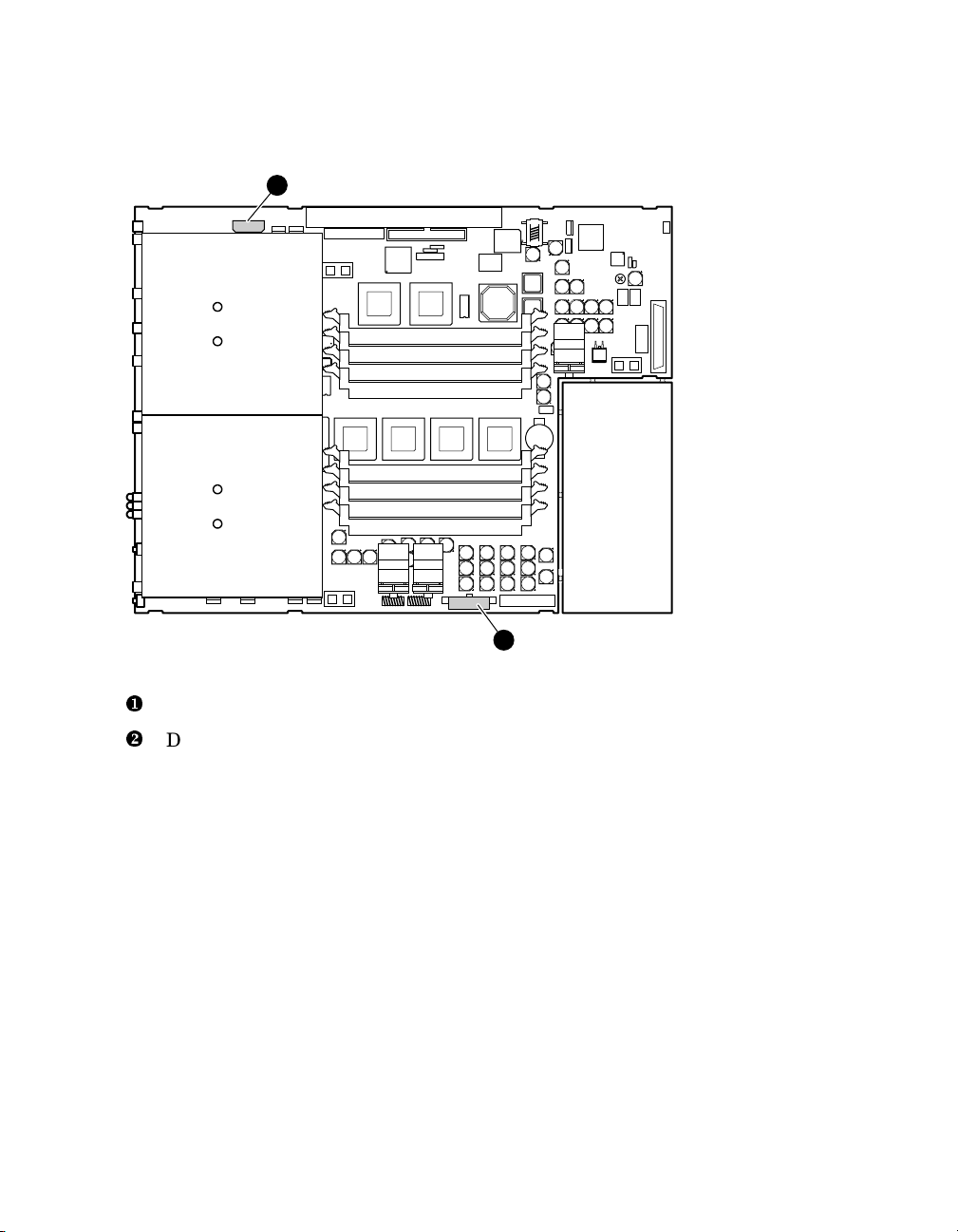
Figure 1-1 Power Connectors
2
Main power connector - one 7x2 (14-pin)
X
Disk power connector - one 4x1 (4-pin)
Y
1
MR0069
1.2.2 Estimated Power Consumption
The typical power consumption for the AlphaServer DS20L is 275 watts AC.
Overview 1-5
Page 18

1.2.3 Environmental
Table 1–2 lists the environmental requirements for the DS20L system.
Table 1– 2 Environmental Parameters
Parameter Specification
Temperature
Non-operating 41 to 122°F/5 to 50°C
Storage (60 days) -40 to 151°F/-40 to 66°C
Relative Humidity
Non-operating 10% to 95%
Storage (60 days) 10% to 95%
Maximum Wet Bulb
Temperature
Storage (60 days) 115°F/46° C
Heat Dissipation
Operating
NOTE: Maximum operating temperature at sea level;
0
reduce by 1.
sea level.
Rate of change
(operating)
Operating 10% to 90%
Operating 82°F/28° C
Non-operating 90°F/32° C
Typical
configuration:
2 GB memory
1 hard disk
1 CD-ROM
2 PCI option
cards
F per 1,000 ft (1.8C per 1,000 m) above
50 to 95°F/10 to 35° C
20°F/hr / 11C° /hr
939 BTU/hr
1-6 AlphaServer DS20L User’s Guide
Page 19

Table 1-2 Environmental Parameters (continued)
Parameter Specification
Airflow and Quality
Exhaust location Rear
Particle size N/A
Concentration N/A
Altitude
Non-operating 40,000 ft/12,192 m
Intake location Front
Operating 10,000 ft/3,048 m
NOTE: Higher altitudes are possible if maximum
operating temperature is reduced (see Temperature);
other restrictions may apply such as maximum
permissible altitude for hard drives.
1.2.3.1 Safety
The AlphaServer DS20L power supply must be connected to a properly
grounded, single-phase AC power outlet.
The DS20L (Series EA2014) system meets registered product-safety
certification for the U.S. and Canadian Underwriters Laboratories (UL and
CUL).
1.2.3.2 EMC
Hewlett-Packard recommends the use of high-quality, shielded cables for all
external I/O.
The AlphaServer DS20L (Series EA2014) meets electro-magnetic compatibility
(EMC) requirements for the following:
• Federal Communications Commission (FCC) 47 CFR Part 15 Class A (USA)
• EN 55022:1998 Class A ITE emissions requirements (EU)
• EN55024:1998 immunity requirements (EU)
Overview 1-7
Page 20

• VCCI Class A ITE (Japan)
• AS/NZS 3548:1995/ Class A ITE (Australia)
• CNS13438 Class A (Taiwan)
• The DS20L is designed for professional use in cluster applications. DS20L
clusters deployed in European Community (EC) countries must be
configured with a minimum of four (4) DS20Ls to meet the requirements of
EN61000-3-2. Hewlett-Packard has certified and labeled the DS20L as
European Conforming (CE) compliant based on the minimum four (4) node
installation requirement.
1.2.3.3 Thermal
The DS20L system is designed with a high-performance cooling system to
maintain internal component temperatures within desired operating ranges.
Proper operation of the cooling system requires that the front of the enclosure
receives an adequate supply of air. If the system is installed behind a grill or
other obstruction, it should be no more restrictive than the standard bezel:
approximately 50% open with no shadows. Table 1–2 lists all relevant
environmental requirements.
1.2.4 Physical
Table 1–3 gives the physical dimensions of the AlphaServer DS20L.
Table 1– 3 Physical Dimensions
Dimension Value
Length 20.5 in / 52 cm
Width 17.5 in / 44.5 cm
Height 1.75 in / 4.5 cm (1U)
Weight 21 lbs / 9.4 kg
1.2.4.1 I/O
The rear-panel connectors are integral to the AlphaServer DS20L chassis. The
system uses a custom I/O board to provide connections for two serial ports, one
parallel port, and two Ethernet RJ45 ports.
The DS20L external rear-panel connectors are shown in Figure 1-5.
1-8 AlphaServer DS20L User’s Guide
Page 21

1.2.5 Acoustical
The following table shows the AlphaServer DS20L (Series EA2014) acoustical
specifications.
Preliminary declared values per ISO 9296 and ISO 7779:
L
With 1 or 0
Idle Operate Idle Operate
6.7
HDD
Current values for specific configurations are available from HewlettPackard representatives. 1 B = 10 dBA.
, B
WAd
6.7
L
(bystander positions)
51
, dBA
pAm
51
Schallemissionswerte — Vorläufige Werteangaben nach
ISO 9296 und ISO 7779/DIN EN27779:
mit 1 oder
0 HDD
Aktuelle Werte für speziele Ausrüstungsstufen sind uber die HewlettPackard Vertretungen erhältelich. 1 B = 10 dBA.
Schalleistungspegel
L
, B
WAd
Leerlauf Betrieb Leerlauf Betrieb
6,7
6,7
Schalldruckpegel
L
, dBA
pAm
Zuschauerpositionen)
(
51
51
Overview 1-9
Page 22
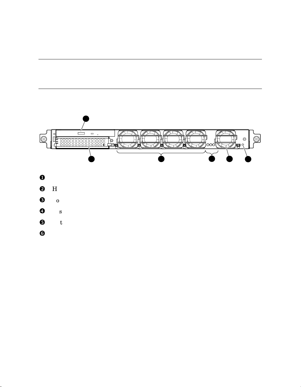
1.3 Front Panel Controls and Indicators
The front panel of the DS20L system contains five fans with connectors
to the motherboard, a slimline CD-ROM drive bay, a hard disk drive
bay, and three LEDs.
Figure 1-2 Front View of the System
1
3
1
2
4
2
CD-ROM drive (optional)
X
Hard disk storage bay
Y
3
5
6
MR0359
Four fans (connected to motherboard)
Z
System LEDs (see Section 5.1 for detailed information)
[
Fifth fan (connected to motherboard)
\
Halt button (recessed in hole)
]
1-10 AlphaServer DS20L User’s Guide
Page 23

1.3.1 Removing the Front Bezel
The front bezel must be removed to insert or eject a CD.
Figure 1-3 shows how to remove the front bezel X from the enclosure Y.
1. Place a finger in each side tab of the bezel and pull it gently forward to
disengage the bezel from the tabs
2. Reverse these procedures to replace the bezel.
Figure 1-3 Removing the Front Bezel
Z
on the front of the enclosure.
2
3
3
AlphaServer DS20L
hp
1
MR0360
1.3.2 Inserting or Ejecting a CD
The front bezel must be removed to insert or eject a CD; refer to 1.3.1. When
you are finished using the CD-ROM drive, reattach the front bezel.
Overview 1-11
Page 24

1.3.3 Halt Button
The AlphaServer DS20L has a Halt button under the front bezel.
The Halt button is accessible through an opening on the front panel of the
system. To use it, remove the bezel (see Section 1.3.1) and insert a slender
object through the access hole to push it in. See Figure 1-4.
Figure 1-4 Halt Button Location
2
X
Y
1-12 AlphaServer DS20L User’s Guide
Halt button recessed in cabinet
Long slender object used to reach button
1
MR0361
Page 25
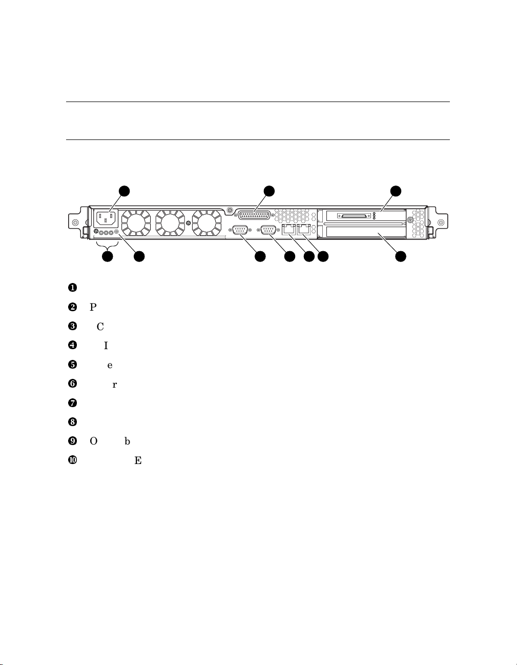
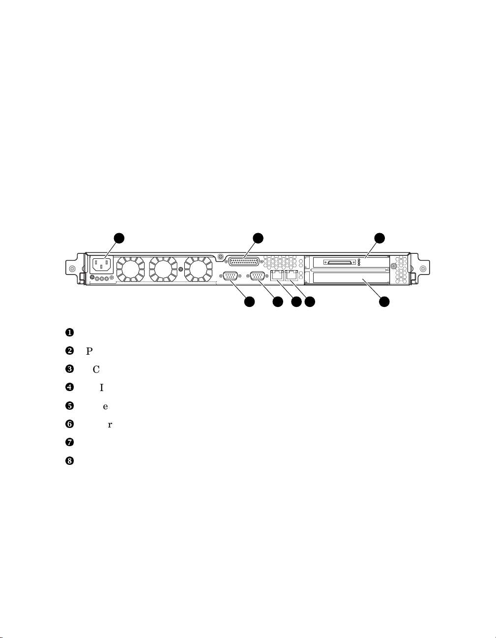
1.4 Rear Panel Ports, Slots, and Indicators
The I/O rear panel contains the dual Ethernet connectors and the
parallel and dual serial connectors.
Figure 1-5 Rear View of the System
1 2 3
1 2 3
10 56789 4
AC power connector
X
Parallel port
Y
PCI bus 1
Z
MR0362
PCI bus 0
[
Ethernet (for Tru64 UNIX, port 1; for Linux, port 0); two LEDs 1
\
Ethernet (for Tru64 UNIX, port 0; for Linux, port 1); two LEDs 1
]
COM1
^
COM2
_
On/Off button
`
System LEDs (See Section 5.1 for detailed information on all LEDs.)
a
Overview 1-13
Page 26
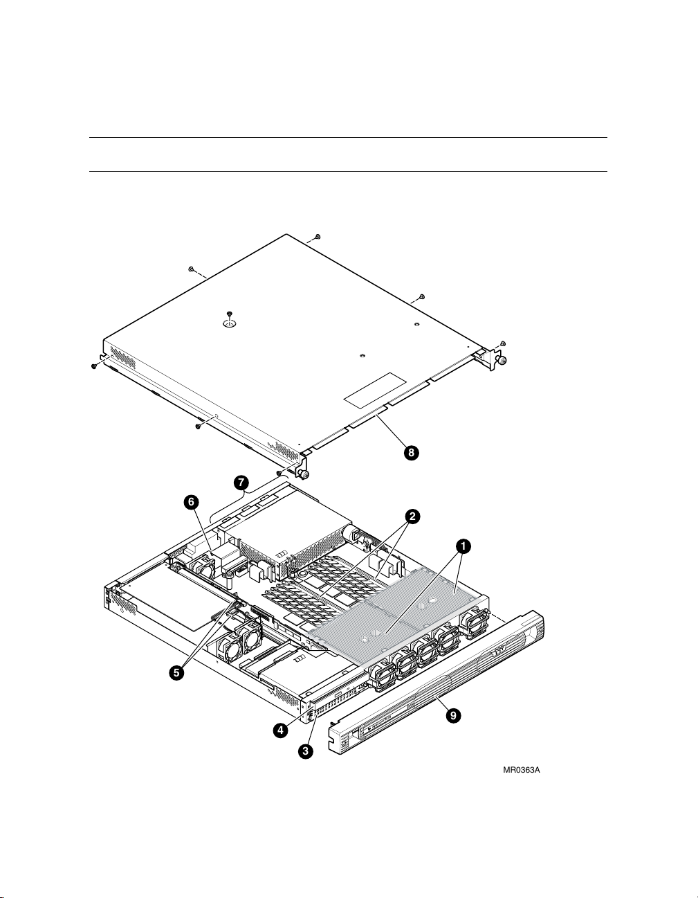
1.5 Internal View of the System
The AlphaServer DS20L has dual CPUs in a 1U enclosure.
Figure 1-6 Internal View of the System
7
6
5
4
3
1-14 AlphaServer DS20L User’s Guide
AlphaServerDS20L
hp
8
2
1
9
MR0363A
Page 27

Dual CPUs; left – CPU 1, right – CPU 0, as oriented in illustration
X
Memory slots
Y
Hard drive bay
Z
CD-ROM bay
[
PCI slots located on the PCI riser
\
I/O daughter card
]
Power supply
^
Cover
_
Front bezel
`
Overview 1-15
Page 28

Page 29
Chapter 2
Installation and Options
2.1 System Setup and Installation
The AlphaServer DS20L is rack-mountable in M-Series racks. Whether
in a rack, or in a stand-alone configuration, first connect all external
devices, then connect the system to a grounded AC power source.
WARNING: To prevent injury, access is limited to persons who
!
have appropriate technical training and experience. Such
persons are expected to understand the hazards of working
within this equipment and take measures to minimize danger to
themselves or others. These measures include:
1. Remove any jewelry that may conduct electricity.
2. Power down the system and wait 2 minutes to allow
components to cool.
3. Wear an anti-static wrist strap when handling internal
components.
WARNING: To prevent injury, unplug the power
cord from each system’s power supply before
installing components.
Installation and Options 2-1
Page 30
2.1.1 Rackmounting
See the documentation that came with your rack rails for installing the
AlphaServer DS20L in an M-Series rack.
2.1.2 Connecting the System
Connect the appropriate external devices first, then connect the AC power cord
to the DS20L and a grounded power source.
Figure 2-1 shows the location of all connectors.
Figure 2-1 Rear Connectors
1 2 3
5678 4
MR0364
AC power connector
X
Parallel port
Y
PCI bus 1
Z
PCI bus 0
[
Ethernet (for Tru64 UNIX, port 1; for Linux, port 0)
\
Ethernet (for Tru64 UNIX, port 0; for Linux, port 1)
]
COM1
^
COM2
_
2-2 AlphaServer DS20L User’s Guide
Page 31

2.2 Installing Options
This section describes how to remove the bezel and/or cover and install
memory, PCI options, CD-ROM, or a hard drive.
2.2.1 Bezel Removal
NOTE: It is not necessary to remove the front bezel to open the cover to access
the inside of the enclosure.
You only have to remove the front bezel if you need to access the front of the
enclosure to insert or remove a CD, to remove or install the hard drive or the
CD-ROM drive, or remove the system from a rack.
X
Figure 2-2 shows how to remove the front bezel
1. Place a finger in each side tab of the bezel and pull it gently forward to
Z
disengage the bezel from the tabs
on the front of the enclosure.
Figure 2-2 Removing the Front Bezel
from the enclosure Y.
2
3
AlphaServer DS20L
hp
3
1
MR0360
Installation and Options 2-3
Page 32

2.3 Removal from a Rack
If the system is mounted in a rack, refer to Figure 2-3 and follow these
procedures to remove it from the rack in order to open the cover.
1. Remove power from the system.
2. Disconnect all external cables from the system.
X
3. Loosen the two captive screws
rack rails, and lift the system forward and out of the rack.
4. To replace the system in the rack, reverse these steps as necessary.
Figure 2-3 Removing the System from a Rack
that hold the system’s chassis slides to the
1
hp
AlphaServer DS20L
FRONT VIEW
AlphaServerDS20L
hp
1
1
1
2-4 AlphaServer DS20L User’s Guide
MR0365
Page 33

2.3.1 Removing the Cover
To remove the cover, refer to Figure 2-4 and follow these steps:
1. Remove power from the system.
X
2. Remove the retaining screw
from the rear of the cover.
3. Remove the top screw
4. Remove three screws
Y
.
Z
from each side of the cover
[
5. Slide the cover back and lift it away from the system.
Figure 2-4 Removing the Cover
1
4
3
3
2
3
.
3
3
3
MR0366
Installation and Options 2-5
Page 34

2.3.2 Memory
Memory may be added to or removed from the AlphaServer DS20L.
Each memory bank has four slots that accept 168-pin PC100 SDRAM PLL
registered/buffered based SPD DIMMs. Memory is supported in a size range
from 512 MB to 2 GB.
There are two DIMM banks designated Bank 0 and Bank 1. The slots are
arranged in an alternating pattern. See Figure 2-5.
2.3.2.1 Memory Configuration Rules
• A bank must be fully populated; that is, all four slots in a given bank (0 or 1)
must be filled.
• Bank 0 must be populated first.
• A bank must use the same type, size, and speed DIMMs. Bank 0 and Bank
1 may have different type, size, and speed of DIMMs from each other,
however.
Figure 2-5 Memory Configuration
1
0
1
0
0
1
0
1
Bank 0
Bank 1
2-6 AlphaServer DS20L User’s Guide
MR0096
Page 35

Refer to Figure 2-6 and follow these steps to add or remove memory.
1. Review the memory configuration and guidelines.
2. Remove the cover (see Section 2.3.1).
X
3. To insert a memory DIMM
and press down gently but firmly to engage the side tabs
, slide it into the appropriate memory slot Y
Z
.
4. To remove a memory DIMM, disengage the side tabs and lift it out from the
slot.
Figure 2-6 Adding or Removing Memory
1
3
2
3
MR0097
Installation and Options 2-7
Page 36

2.3.3 PCI Options
Refer to Figure 2-7 and follow these steps to add or remove PCI options.
CAUTION: To prevent over-flexing the PCI riser or module, use your hands to
support them as you install or remove the PCI module.
1. Remove the cover (see Section 2.3.1).
X
2. Determine the slot
retaining screw and slot cover to expose the slot.
3. Line up the fingers and the notch on the PCI module with the appropriate
connector on the PCI riser
press the module into place in the slot.
4. Insert the retaining screw
module’s bracket
To remove a PCI module, remove the retaining screw. Grasp the PCI module
and work out from its connector on the PCI riser.
you wish to use for the PCI module
Z
. While supporting the back of the PCI riser,
[
through the side of the enclosure and the PCI
\
.
Y
. Remove the
2-8 AlphaServer DS20L User’s Guide
Page 37

Figure 2-7 Adding or Removing a PCI Module
3
1
2
5
4
2.3.4 Hard Drive
Follow these steps to add or remove a SCSI hard drive.
1. Remove the front bezel (see Section 2.2.1) and cover (Section 2.3.1).
X
2. See Figure 2-8. Install the SCSI hard drive backplane
DS20L-AA SCSI cable kit) onto its connector on the back of the SCSI hard
drive. Attach the power cable connector
the backplane
Z
.
Y
, and one end of the data cable to
(part of CK-
MR0367
Installation and Options 2-9
Page 38

Figure 2-8 Installing the SCSI Backplane
3
2
1
MR0368
3. Lift the PCI riser and route the SCSI hard drive cable (17-05034-06) under
the notch in the PCI riser card by following these steps.
a. Refer to Figure 2-7 to remove any PCI option modules, then refer to
Figure 2-9 for the remainder of these procedures.
X
CAUTION: Do not remove the PCI fan bracket
during these procedures.
It holds and supports the motherbard in place, making it easier
to unplug and lift the PCI riser.
b. Remove both screws attaching the PCI riser to its rear bracket
c. Pull up on the entire PCI riser
Z
and slide it up and lift it free of the
Y
.
enclosure.
2-10 AlphaServer DS20L User’s Guide
Page 39
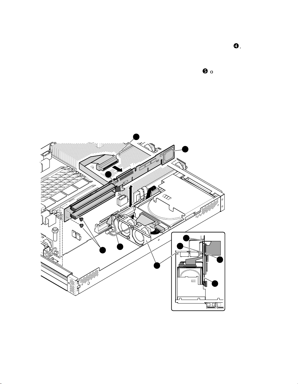
d. Route the SCSI cable through the notch in the PCI fan bracket
end of the SCSI cable was connected to the SCSI backplane in Step 3,
above.
\
e. Slide the protector on the SCSI cable into the notch
on the PCI riser.
f. Push down firmly and squarely on the PCI riser to seat it back in the
motherboard (making sure that the cable remains positioned in the
notch) and secure the two screws to the rear bracket.
g. Connect the end of the SCSI cable to its connector on the PCI riser.
Figure 2-9 Routing SCSI Cable to the PCI Riser
6
3
[
. One
5
FRONT
FRONT
3
MR0369
6
5
4
2
1
4
Installation and Options 2-11
Page 40

4. See Figure 2-10. Assemble the SCSI drive carrier by attaching the right and
X
left arms
ensuring that the handle
with four tension clips Y and four UNC screws Z as shown,
[
is secured to the drive \ by the front of the
arms.
NOTE: When installing the arms, bias them upward as high as possible on the
disk to ensure that the disk does not interfere with the CD-ROM.
Figure 2-10 Assembling and Installing the SCSI Hard Drive Carrier
4
3
1
4
5
2
5. See Figure 2-11; with the handle
hard drive and carrier
Y
into the enclosure Z. Ensure that the drive is
X
connected securely into the SCSI backplane
2-12 AlphaServer DS20L User’s Guide
MR0348
rotated forward, slide the assembled
[
as shown.
Page 41

\
or
]
6. Insert the hard drive shield, either
from right to left to seat the left-hand tabs. (Use
drive; use
]
if your system does not have a CD-ROM drive.) Secure the
drive with the captive snap-in fastener
, into the enclosure, sliding it
\
if you have a CD-ROM
^
or _.
CAUTION: If you are installing a SCSI drive, prevent over-flexing backplane by
using your hand to support the backplane as you slide the drive into
its connector.
Figure 2-11 Installing the Hard Drive Assembly
4
3
2
1
6
5
7
8
MR0370
7. To remove a SCSI hard drive assembly from the system, the hard drive
carrier from the drive, the SCSI backplane, or hard drive cables, reverse
these steps as necessary.
Installation and Options 2-13
Page 42

2.3.5 CD-ROM
A CD-ROM may be added to or removed from the AlphaServer DS20L.
NOTE: If you are installing a CD-ROM for the first time, you will have to
remove the hard drive shield that is on your system (Figure 2-11 \),
and replace it with the one that came with the CD-ROM drive (Figure
2-11,
]
), to allow access to operate the CD-ROM.
To add or remove a CD-ROM, refer to Figure 2-12 and follow these steps.
1. Remove the front bezel (see Section 2.2.1) and cover (Section 2.3).
X
2. Install the CD-ROM backplane
cable
Y
(17-05140-01), route it over the PCI riser, and connect the other
end to the motherboard as shown
, attach the combined power and data
Z
.
3. Slide the CD-ROM
4. Push the CD-ROM backplane into its connector on the CD-ROM, and attach
the two screws
To remove a CD-ROM or the CD-ROM backplane from the system, reverse these
steps as necessary.
NOTE: To access the CD-ROM carrier tray after installation, it is necessary to
remove the front bezel (see Section 2.2.1) and replace it when you are
through.
[
rearward into its bay.
\
that hold it in place.
2-14 AlphaServer DS20L User’s Guide
Page 43
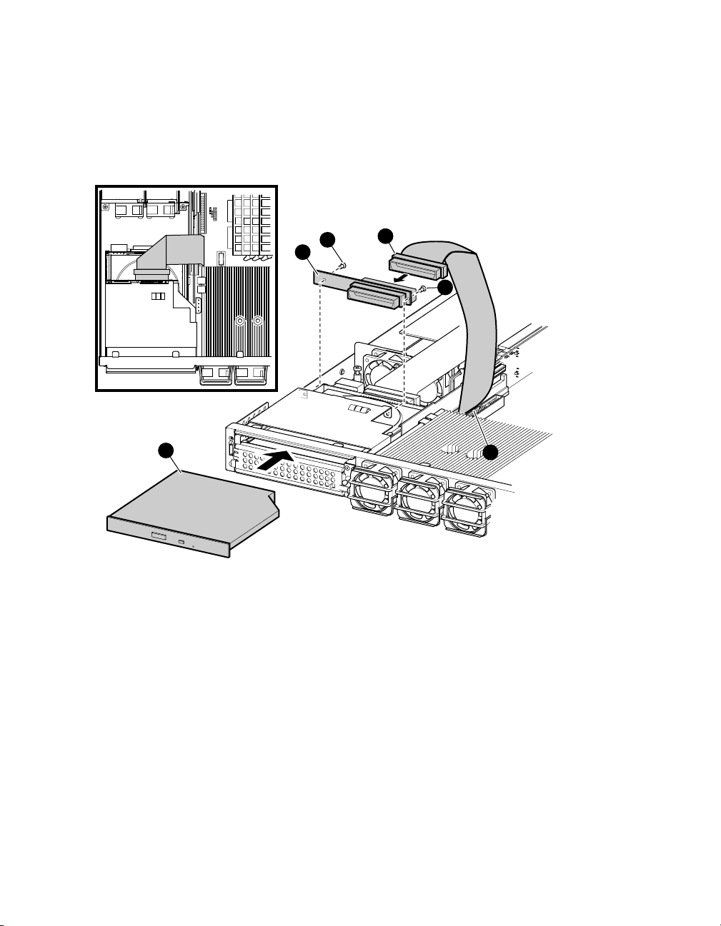
Figure 2-12 Installing the CD-ROM
TOP VIEW
5
1
4
2
5
3
MR0372
Installation and Options 2-15
Page 44

Page 45

Chapter 3
Operation
3.1 Powering Up the System
This section describes how to turn on the system and what happens
when you do.
3.1.1 Turning the System On
After installing the system as discussed in Chapter 2, push the On/Off button to
`
power up the system (see Figure 1-5
Check the LEDs to ensure that the system has power and that there are no
initial errors.
for the location of the On/Off button).
3.1.1.1 LEDs
There are two sets of LED system status indicators on the AlphaServer DS20L,
one set on the front of the system (see Figure 1-2
(see Figure 1-5
indicate speed and activity (Figure 1-5
See Section 5.1 for a listing of all LEDs and their meaning.
a
). Also, each of the network connectors has two LEDs that
\
and ]).
[
), and one set on the rear
3.1.2 SROM Code
When the system is turned on or reset, SROM code automatically loads into
Icache in each CPU. The SROM code then:
• Initializes the CPU.
• Detects configuration jumpers and CPU memory configuration.
• Initializes chipset values, including memory timing, Cchip, Dchip, and
Pchip registers.
Operation 3-1
Page 46

• Performs power-on self-test (POST) of the basic system needed to run
diagnostics (memory, etc.).
• Initializes the system memory.
• Initializes the L2 cache.
• Loads diagnostic firmware used by Hewlett-Packard Customer Services
engineers.
3.1.4 Alpha SRM Console
The Alpha SRM console firmware provides service functions commonly provided
in most computer systems, including the following:
• I/O subsystem initialization
• Operator interface
• OS bootstrap and restart
The SRM console firmware provides Palcode for Tru64 UNIX operating
systems.
Users communicate with the SRM console via the COM1/COM2 serial ports.
SRM console firmware supports the use of the VT-style terminal attached to the
standard serial ports. The SRM console firmware provides a command-line
interface with a single UNIX-like shell that has a simple scripting facility. The
default settings for COM1/COM2 are 9600 baud, 1 stop bit, and no parity.
3-2 AlphaServer DS20L User’s Guide
Page 47

3.1.5 Power-Up Display
The power-up display shows the results of power-on self-test (POST).
AlphaServer DS20L systems may have various options that will cause the
power-up display to differ slightly from the sample shown here.
Testing begins after pressing the On/Off button, and screen text similar to that
in Example 3–1 displays.
Example 3–1 Power-Up Display - Serial Console
!!
initializing GCT/FRU at 1e0000
Testing the System
Testing the Memory
Testing the Disks (read only)
Testing ei* devices.
hp AlphaServer DS20L 833 MHz Console V5.9-16, 18-OCT-2001 15:38:57
P00>>>
P00>>>
X
The SRM console banner and prompt P00>>> are printed.
X
The SRM console is a command-line interface you use to set or read system
parameters.
If the auto_action environment variable is set to boot or restart and the
os_type environment variable is set to unix, the system will automatically
boot the Tru64 UNIX operating system and not halt at the SRM console
(assuming a bootable Tru64 UNIX disk is available and boot parameters
are properly set) Refer to Section 3.2.1 for details.
Operation 3-3
Page 48

3.2 Operating Systems
This section discusses booting the Tru64 UNIX and the Linux operating
systems, and starting an installation of the operating systems.
NOTE: Your system may have factory-installed software (FIS); that is, the
operating system has already been installed. If so, refer to the FIS
documentation included with your system to boot the operating system
for the first time. Linux-ready systems do not come with factoryinstalled software.
3.2.1 Setting Boot Options
You can set a default boot device, boot flags, and network boot
protocols by using the SRM set command with environment variables.
Once these environment variables are set, the boot command defaults
to the stored values. You can override the stored values for the current
boot session by entering parameters on the boot command line.
auto_action
bootdef_dev
boot_file
boot_osflags
ei*0_inet_init or
ew*0_inet_init
ei*0_protocols or
ew*0_protocols
3-4 AlphaServer DS20L User’s Guide
Determines the default action the system takes when the
system is power cycled, reset, or experiences a failure.
Device or device list from which booting is to be attempted
when no path is specified on the command line.
Specifies a default file name to be used for booting when
no file name is specified by the boot command.
Defines parameters (boot flags) used by the operating
system to determine some aspects of a system bootstrap.
Determines whether the interface’s internal Internet
database is initialized from nvram or from a network
server (through the bootp protocol). Set this environment
variable if you are booting Tru64 UNIX from a RIS server.
Defines a default network boot protocol (bootp or mop).
Page 49

3.2.1.1 auto_action
The SRM auto_action environment variable determines the default
action the system takes when the system is power cycled, reset, or
experiences a failure.
Systems can boot automatically (if set to autoboot) from the default boot device
under the following conditions:
• When you first turn on system power
• When you power cycle or reset the system
• When system power comes on after a power failure
• After a panic
The factory setting for auto_action is halt. The halt setting causes the system
to stop in the SRM console. You must then boot the operating system manually.
For maximum system availability, auto_action can be set to boot or restart.
• With the boot setting, the operating system boots automatically after the
SRM init command is issued.
• With the restart setting, the operating system boots automatically after the
SRM init command is issued, and it also reboots after an operating system
crash.
Example
To set the default action to boot, enter the following SRM commands:
P00>>> set auto_action boot
P00>>> init
Operation 3-5
Page 50

3.2.1.2 bootdef_dev
The bootdef_dev environment variable specifies one or more devices
from which to boot the operating system. When more than one device is
specified, the system searches in the order listed and boots from the
first device.
Enter the show bootdef_dev command to display the current default boot
device. Enter the show device command for a list of all devices in the system.
The syntax is:
set bootdef_dev boot_device
boot_device
Example
In this example, two boot devices are specified. The system will try booting
from dqb0 and, if unsuccessful, will boot from dkb0.
P00>>> set bootdef_dev dqb0, dkb0
NOTE: When you set the bootdef_dev environment variable, it is recom-
The name of the device on which the system software has been
loaded. To specify more than one device, separate the names with
commas.
mended that you set the operating system boot parameters as well,
using the set boot_osflags command.
3-6 AlphaServer DS20L User’s Guide
Page 51

3.2.1.3 boot_file
The boot_file environment variable specifies the default file name to be
used for booting when no file name is specified by the boot command.
The syntax is:
set boot_file filename
Example
P00>>> set boot_file “”
NOTE: This command clears the boot file setting and sets the string to empty.
Operation 3-7
Page 52

3.2.1.4 boot_osflags
The boot_osflags environment variable sets the default boot flags.
Boot flags contain information used by the operating system to determine some
aspects of a system bootstrap. Under normal circumstances, you can use the
default boot flag settings.
To change the boot flags for the current boot only, use the flags_value argument
with the boot command.
The syntax is:
set boot_osflags flags_value
The flags_value argument is specific to the operating system.
Tru64 UNIX Systems
Tru64 UNIX systems take a single ASCII character as the flags_value
argument.
Load operating system software from the specified boot device
a
(autoboot). Boot to multiuser mode.
Prompt for the name of a file to load and other options (boot
i
interactively). Boot to single-user mode.
Stop in single-user mode. Boots /vmunix to single-user mode and stops
s
at the # (root) prompt.
Full dump; implies “s” as well. By default, if Tru64 UNIX crashes, it
D
completes a partial memory dump. Specifying “D” forces a full dump at
system crash.
Example
The following setting will autoboot Tru64 UNIX to multiuser mode when you
enter the boot command.
P00>>> set boot_osflags a
3-8 AlphaServer DS20L User’s Guide
Page 53

Linux Systems
If aboot.conf contains (0: 1/vmlinux.gz ro root=/dev/sda2), the system can be
booted by one of the following methods:
1.
set boot_file
set boot_osflags 0
boot dkb0
---or---
2.
boot dkb0 -file "" -flags 0
---or---
3.
set boot_file 1/vmlinuz.gz
set boot_osflags "ro root=/dev/sda2"
boot dkb0
Example
Single-user mode is typically used for troubleshooting. To make system changes
at this run level, you must have read/write privileges. The command to boot
Linux into single-user mode is similar to the following example where “f” root is
in partition 2 of dka0, and the kernel is in /boot/Compaq.gz.
P00>>> boot –file “l/vmlinux.gz” –flags “root=/dev/sda2 rw single”
Example
The following command sets the boot_osflags environment variable for Linux:
P00>>> set boot_osflags 0
Operation 3-9
Page 54

3.2.1.5 ei*0_inet_init or ew*0_inet_init
The ei*0_inet_init or ew*0_inet_init environment variable determines
whether the interface’s internal Internet database is initialized from
nvram or from a network server (through the bootp protocol).
Legal values are nvram and bootp. The default value is bootp. Set this
environment variable if you are booting Tru64 UNIX from a RIS server.
To list the network devices on your system, enter the show device command.
The Ethernet controllers start with the letters “ei” or “ ew,” for example, ewa0.
The third letter is the adapter ID for the specific Ethernet controller. Replace
the asterisk (*) with the adapter ID letter when entering the command.
The syntax is:
set ei*0_inet_init value or
set ew*0_inet_init value
Example
P00>>> set ewa0_inet_init bootp
3-10 AlphaServer DS20L User’s Guide
Page 55

3.2.1.6 ei*0_protocols or ew*0_protocols
The ei*0_protocols or ew*0_protocols environment variable sets
network protocols for booting and other functions.
To list the network devices on your system, enter the show device command.
The Ethernet controllers start with the letters “ei” or “ ew,” for example, ewa0.
The third letter is the adapter ID for the specific Ethernet controller. Replace
the asterisk (*) with the adapter ID letter when entering the command.
The syntax is:
set ei*0_protocols protocol_value or
set ew*0_protocols protocol_value
The option for protocol_value is limited to bootp:
bootp
Example
P00>>> show device
.
.
.
ewa0.0.0.1001.0 EWA0 08-00-2B-3E-BC-B5
ewb0.0.0.12.0 EWB0 00-00-C0-33-E0-0D
ewc0.0.0.13.0 EWC0 08-00-2B-E6-4B-F3
.
.
.
P00>>> set ewa0_protocols bootp
P00>>> show ewa0_protocols
ewa0_protocols bootp
Sets the network protocol to bootp, the setting typically used
with the Tru64 UNIX operating system.
Operation 3-11
Page 56

3.2.2 Booting Tru64 UNIX
Tru64 UNIX can be booted from a local disk or from a Remote
Installation Services (RIS) server over a local area network.
To boot from a RIS server, you must first register your system as a RIS client.
Refer to the Tru64 UNIX Sharing Software on a Local Area Network manual for
information about setting up and using RIS and the Tru64 UNIX Installation
Guide - Advanced Topics manual for information about installing Tru64 UNIX
from a RIS server.
3.2.2.1 Booting from a Local Disk
\
Example 3– 2 Booting Tru64 UNIX from a Local Disk
P00>>> sh boot* X
boot_dev dkb0.0.0.5.0
boot_file
boot_osflags A
boot_reset OFF
bootbios
bootdef_dev dkb0.0.0.5.0
booted_dev
booted_file
booted_osflags
P00>>> show device
dkb0.0.0.5.0 DKB0 COMPAQ BF01865222 B004
dqb0.0.1.16.0 DQB0 SAMSUNG CD-ROM SN-124 q008
eia0.0.0.3.1 EIA0 00-02-56-00-08-7A
eib0.0.0.4.0 EIB0 00-02-56-00-08-79
pka0.7.0.3.0 PKA0 SCSI Bus ID 7
pkb0.7.0.5.0 PKB0 SCSI Bus ID 7
P00>>> b
(boot dkb0.0.0.5.0 -flags A)
block 0 of dkb0.0.0.5.0 is a valid boot block
reading 14 blocks from dkb0.0.0.5.0
bootstrap code read in
base = 200000, image_start = 0, image_bytes = 1c00
initializing HWRPB at 2000
initializing page table at 1ff4a000
initializing machine state
setting affinity to the primary CPU
jumping to bootstrap code
.
The system is ready.
Compaq Tru64 UNIX V5.1A (Rev. 1885) (hpsq5) console
login:
[
Y
Z
3-12 AlphaServer DS20L User’s Guide
Page 57

X
The show boot command displays the current default boot device.
Y
The show device command displays device information, including
name and type of connection to the system.
Z
The operating system is on this device. The name of this device, dkb0,
is used as an argument to the boot command.
[
This command loads Tru64 UNIX from the disk dkb0, using the boot
file vmunix and autobooting to multiuser mode.
The boot command accepts the name of a boot device, a boot file
name through the -file option, and boot flags through the -flags
option. The environment variables bootdef_dev, boot_file, and
boot_osflags can also be used to specify the default boot device or
device list, the default boot file, and flag information. When an option
and the corresponding environment variable are both in a command
string, the option overrides the environment variable. The value of
the environment variable, however, is not changed.
The operating system banner displays.
\
Operation 3-13
Page 58

3.2.2.2 Booting from a Remote Disk
Example 3– 3 Booting Tru64 UNIX from a Remote Disk
P00>>> show device
. . .
eia0.0.3.1 EIA0 08-00-2B-E2-9C-60
>>>
>>> boot -flags an -protocols bootp eia0
(boot eia0.0.3.1 -flags an)
Building FRU table
Trying BOOTP boot
Broadcasting BOOTP Request...
Received BOOTP Packet File Name: /var/adm/ris/ris0.alpha/hvmunix
local inet address: 16.122.128.26
remote inet address: 16.122.128.59
TFTP Read File Name: /var/adm/ris/ris0.alpha/hvmunix
..........................................................................................
bootstrap code read in
base = 200000, image_start = 0, image_bytes = 9a0fa0
initializing HWRPB at 2000
initializing page table at 1f2000
initializing machine state
setting affinity to the primary CPU
jumping to bootstrap code
Secondary boot program - Thu Oct 18 22:33:13 EST 2001
Loading vmunix ...
.
.
.
The system is ready.
Tru64 UNIX Version V5.1A (sabl28.eng.pko.dec.com) console
.
X
Y
Z
[
3-14 AlphaServer DS20L User’s Guide
Page 59

X
The show device command displays device information, including
name and type of connection to the system.
Y
The operating system is on a remote disk, eia0. The name of this
device, eia0, is used as an argument to the boot command.
Z
This command loads Tru64 UNIX from eia0, autobooting to multiuser
mode.
The boot command accepts the name of a boot device, a boot file
name through the -file option, and boot flags through the -flags
option. The environment variables bootdef_dev, boot_file, and
boot_osflags can also be used to specify the default boot device or
device list, the default boot file, and flag information. When an option
and the corresponding environment variable are both in a command
string, the option overrides the environment variable. The value of
the environment variable, however, is not changed.
The operating system banner displays.
[
Operation 3-15
Page 60

3.2.3 Starting a Tru64 UNIX Installation
Tru64 UNIX can be installed from the CD-ROM drive connected to the
system or from a Remote Installation Services (RIS) server over a local
area network. The user interface that you see after you boot your
system depends on whether your system console is a VGA monitor or a
serial terminal.
To install the operating system from a RIS server, you must first register your
system as a RIS client. Refer to the Tru64 UNIX Sharing Software on a Local
Area Network manual for information about setting up and using RIS and the
Tru64 UNIX Installation Guide - Advanced Topics manual for information
about installing Tru64 UNIX from a RIS server.
3.2.3.1 NHD4 and IPK Compatibility
You must install the NHD4 kit during a full installation of the operating system
on a DS20L system. The kernel modules for the DS20L are included in the
NHD4 kit. When you install NHD4, you must also install the most current
TRU64 UNIX patch kit before you return your system to production. It does not
matter which one you install first.
Example 3– 4 Text-Based Installation Display
P00>>> b dqb0
(boot dqb0.0.1.16.0 -flags a)
block 0 of dqb0.0.1.16.0 is a valid boot block
reading 16 blocks from dqb0.0.1.16.0
bootstrap code read in
base = 200000, image_start = 0, image_bytes = 2000
initializing HWRPB at 2000
initializing page table at 1fff0000
initializing machine state
setting affinity to the primary CPU
jumping to bootstrap code
Tru64 UNIX boot - Thu Oct 18 15:03:19 EST 2001
Loading vmunix ...
.
.
Initializing system for Tru64 UNIX installation. Please wait...
*** Performing CDROM Installation
3-16 AlphaServer DS20L User’s Guide
Page 61

Loading installation process and scanning system hardware.
Welcome to the UNIX Installation Procedure
This procedure installs UNIX onto your system. You will be asked a
series of system configuration questions. Until you answer all
questions, your system is not changed in any way.
During the question and answer session, you can go back to any
previous question and change your answer by entering: history
You can get more information about a question by entering: help
There are two types of installations:
o The Default Installation installs a mandatory set of
software subsets on a predetermined file system layout.
o The Custom Installation installs a mandatory set of
software subsets plus optional software subsets that you
select. You can customize the file system layout.
The UNIX Shell option puts your system in single-user mode with
superuser privileges. This option is provided for experienced UNIX
system administrators who want to perform file system or disk
maintenance tasks before the installation.
The Installation Guide contains more information about installing
UNIX.
1) Default Installation
2) Custom Installation
3) UNIX Shell
Enter your choice:
1. Boot the operating system from the CD-ROM drive connected to the system.
2. Follow the UNIX installation procedure that is displayed after the
installation process is loaded.
A text-based installation procedure is displayed, as shown in Example 3–4.
Enter the choices appropriate for your system.
See the Tru64 UNIX Installation Guide for complete installation instructions.
Operation 3-17
Page 62

3.2.4 Installing and Booting Linux
Obtain the Linux installation document and install Linux on the
system. Then verify the firmware version, boot device, and boot
parameters, and issue the boot command.
You need V5.6-3 or higher of the SRM console to install Linux. If you have a
lower version of the firmware, you will need to upgrade. For instructions and
the latest firmware images, see the following URL.
http://ftp.digital.com/pub/DEC/Alpha/firmware/
The procedure for installing Linux on an Alpha system is described in the Alpha
Linux installation document for your Linux distribution. The installation
document can be downloaded from the following Web site:
http://www.compaq.com/alphaserver/linux
Linux Boot Procedure
1. Power up the system to the SRM console and enter the show version
command to verify the firmware version.
P00>> show version
version V5.6-3 Mar 12 2001 08:36:11
P00>>
2. Enter the show device command to determine the unit number of the
drive for your boot device, in this case dkb0.0.0.5.0.
P00>>> show device
dkb0.0.0.5.0 DKB0 COMPAQ BF01865222 B004
dqb0.0.1.16.0 DQB0 SAMSUNG CD-ROM SN-124 q008
eia0.0.0.3.1 EIA0 00-02-56-00-08-7A
eib0.0.0.4.0 EIB0 00-02-56-00-08-79
pka0.7.0.3.0 PKA0 SCSI Bus ID 7
pkb0.7.0.5.0 PKB0 SCSI Bus ID 7
P00>>>
3-18 AlphaServer DS20L User’s Guide
Page 63

3. Ensure that the SRM console environment sysvar is set to 5 prior to
installing or booting Linux.
P00>>> set sysvar 5
P00>>> init
4. When switching back from Linux to Tru64 UNIX, verify that the SRM
console environment sysvar is equal to 12.
P00>>> set sysvar 12
P00>>> init
5. After installing Linux, set boot environment variables appropriately for
your installation. The typical values indicating booting from dka0 with the
first aboot.conf entry are shown in this example.
P00>>> set bootdef_dev dkb0
P00>>> set boot_file
P00>>> set boot_osflags 0
P00>>> show boot*
boot_dev dkb0.0.0.5.0
boot_file
boot_osflags 0
boot_reset OFF
bootdef_dev
booted_dev
booted_file
booted_osflags
6. From SRM enter the boot command. Example 3–5 shows an abbreviated
boot output. This example shows messages similar to what you will see
when booting Linux. The example is from a RedHat Linux 7.0 boot.
Example 3– 5 Linux Boot Output
>>> boot
(boot dka0.0.0.8.0 -flags 0)
block 0 of dka0.0.0.8.0 is a valid boot block
reading 163 blocks from dka0.0.0.8.0
bootstrap code read in
base = 2d4000, image_start = 0, image_bytes = 14600
initializing HWRPB at 2000
initializing page table at 7fff0000
initializing machine state
setting affinity to the primary CPU
jumping to bootstrap code
aboot: Linux/Alpha SRM bootloader version 0.7
aboot: switching to OSF/1 PALcode version 1.87
aboot: booting from device ’SCSI 0 8 0 0 0 0 0’
Operation 3-19
Page 64

aboot: valid disklabel found: 3 partitions.
aboot: loading uncompressed vmlinuz-2.4.3-7privateer2smp...
aboot: loading compressed vmlinuz-2.4.3-7privateer2smp...
aboot: zero-filling 369720 bytes at 0xfffffc0000ce9400
aboot: starting kernel vmlinuz-2.4.3-7privateer2smp with
arguments root=/dev/sda2 console=ttyS0
Linux version 2.4.3-7privateer2smp (root@privateer) (gcc
version 2.96 20000731 (Red Hat Linux 7.1 2.96-85)) #1 SMP Thu
May 24 11:01:14 EDT 2001
Booting GENERIC on Titan variation Privateer using machine
vector PRIVATEER from SRM
Command line: root=/dev/sda2 console=ttyS0
memcluster 0, usage 1, start 0, end 362
memcluster 1, usage 0, start 362, end 262135
memcluster 2, usage 1, start 262135, end 262144
freeing pages 362:1024
freeing pages 1700:262135
SMP: 4 CPUs probed -- cpu_present_mask = f
On node 0 totalpages: 262144
.
.
.
autorun ...
... autorun DONE.
NET4: Linux TCP/IP 1.0 for NET4.0
IP Protocols: ICMP, UDP, TCP, IGMP
IP: routing cache hash table of 16384 buckets, 256Kbytes
TCP: Hash tables configured (established 524288 bind 65536)
Linux IP multicast router 0.06 plus PIM-SM
NET4: Unix domain sockets 1.0/SMP for Linux NET4.0.
VFS: Mounted root (ext2 filesystem) readonly.
Freeing unused kernel memory: 432k freed
.
.
.
login:
3-20 AlphaServer DS20L User’s Guide
Page 65

3.3 Updating Firmware
Start the Loadable Firmware Update (LFU) utility by issuing the lfu
command at the SRM console prompt, booting it from the CD-ROM
while in the SRM console.
Example 3– 6 Starting LFU from the SRM Console
Revision levels and devices listed are for example only; your results may vary.
>>> lfu
Checking dqb0.0.1.16.0 for the option firmware files. . .
Option firmware files were not found on CD or floppy.
If you want to load the options firmware,
please enter the device on which the files are located(ewa0),
or just hit <return> to proceed with a standard console update: dqb0
Please enter the name of the options firmware files list, or
Hit <return> to use the default filename (ds20lfw.txt) :
Copying filename.txt from dqb0. . .
Copying filename1.ROM from dqb0. . .
Copying filename2.ROM from dqb0. . .
***** Loadable Firmware Update Utility *****
----------------------------------------------------------------------------
Function Description
----------------------------------------------------------------------------
Display Displays the system’s configuration table.
Exit Done exit LFU (reset).
List Lists the device, revision, firmware name, and update revision.
Readme Lists important release information.
Update Replaces current firmware with loadable data image.
Verify Compares loadable and hardware images.
? or Help Scrolls this function table.
----------------------------------------------------------------------------
UPD> update *
Confirm update on:
srm
[Y/(N)]y
WARNING: updates may take several minutes to complete for each device.
DO NOT ABORT!
srm Updating to 5.9-16... Verifying 5.9-16... PASSED.
UPD> exit
Operation 3-21
Page 66

NOTE: If the system has been shut down from a booted program (most
commonly, the operating system) or in some other way halted back to
the SRM console, the system must be reset before running LFU.
Use the Loadable Firmware Update (LFU) utility to update system firmware.
From the SRM console, start LFU by issuing the lfu command (see
Example 3–6).
A typical update procedure is:
1. Start LFU.
2. Use the LFU list command to show the revisions of modules that LFU can
update and the revisions of update firmware.
3. Use the LFU update command to write the new firmware.
4. Use the LFU exit command to go back to the console.
3-22 AlphaServer DS20L User’s Guide
Page 67

3.3.1 Updating Firmware from a Network Device
Updating firmware from a network device can be done using the bootp
command or using a local MOP server.
Example 3– 7 Updating Firmware from a Network Device
P00>>> boot –file ds20lsrm
X
–proto bootp eia0
(boot eia0.0.0.3.1 -flags A)
Trying BOOTP boot.
Broadcasting BOOTP Request...
..
Name of the firmware image (.exe extension) to be loaded.
X
You can also use the default image using this command.
P00>>> b eia0
Example 3– 8 Updating Firmware Using a MOP Server
Before starting a network upgrade, download the update files from the Internet.
You will need the files with the extension .SYS. Copy these files to your local
MOP server’s MOP load area.
P00>>> boot –file v5917_shupdate X –proto mop eia0
(boot eia0.0.0.3.1 -file v5917_shupdate -flags A)
Trying MOP boot.
.......................
Network load complete.
Host name: BESSIE
Host address: aa-00-04-00-06-74
bootstrap code read in
base = 200000, image_start = 0, image_bytes = 157c00
initializing HWRPB at 2000
initializing page table at 3ff48000
initializing machine state
setting affinity to the primary CPU
jumping to bootstrap code
1536 Meg of system memory
initializing GCT/FRU at 3ff3c000
Operation 3-23
Page 68

***** Loadable Firmware Update Utility *****
-----------------------------------------------------------------------------
Function Description
-----------------------------------------------------------------------------
Display Displays the system’s configuration table.
Exit Done exit LFU (reset).
List Lists the device, revision, firmware name, and update revision.
Readme Lists important release information.
Update Replaces current firmware with loadable data image.
Verify Compares loadable and hardware images.
? or Help Scrolls this function table.
-----------------------------------------------------------------------------
UPD> u srm
Confirm update on:
srm
[Y/(N)]y
WARNING: updates may take several minutes to complete for each device.
DO NOT ABORT!
srm Updating to 5.9-17... Verifying 5.9-17... PASSED.
UPD> ex
Initializing....
Initializing...1536 Meg of system memory
initializing GCT/FRU at 1e0000
Testing the System
Testing the Memory
Testing ei* devices.
hp AlphaServer DS20L 833 MHz Console V5.9-17, Nov 28 2001 09:20:22
P00>>>
Name of the firmware image (.SYS extension) to be loaded.
X
3-24 AlphaServer DS20L User’s Guide
Page 69

3.3.2 LFU Commands
The commands summarized in Table 3– 1 are used to update system
firmware. See Section A.13 for an example of the LFU command
output.
Table 3– 1 LFU Command Summary
Command Function
display
help
readme
update
verify
display
The display command shows the physical configuration of the system. Display
is equivalent to issuing the SRM console command show configuration.
Because it shows the slot for each module, display can help you identify the
location of a device.
exit
The exit command terminates the LFU program, causes system initialization
and testing, and returns the system to the console from which LFU was called.
Shows the physical configuration of the system.
exit
Terminates the LFU program.
Displays the LFU command list.
lfu
Restarts the LFU program.
list
Displays the inventory of update firmware on the selected device.
Lists release notes for the LFU program.
Writes new firmware to the module.
Reads the firmware from the module into memory and compares
it with the update firmware.
Operation 3-25
Page 70

help
The help (or ?) command displays the LFU command list, shown below.
---------------------------------------------------------------------
Function Description
---------------------------------------------------------------------
Display Displays the system’s configuration table.
Exit Done exit LFU (reset).
List Lists the device, revision, firmware name, and update
revision.
Lfu Restarts LFU.
Readme Lists important release information.
Update Replaces current firmware with loadable data image.
Verify Compares loadable and hardware images.
? or Help Scrolls this function table.
----------------------------------------------------------
lfu
The lfu command restarts the LFU program. This command is used when the
update files are on a floppy disk. The files for updating both console firmware
and I/O firmware are too large to fit on a 1.44 MB disk, so only one type of
firmware can be updated at a time. Restarting LFU enables you to specify
another update file.
list
The list command displays the inventory of update firmware on the CD-ROM,
network, or floppy. Only the devices listed at your terminal are supported for
firmware updates.
The list command shows three pieces of information for each device:
• Current Revision — The revision of the device’s current firmware
• Filename — The name of the file used to update that firmware
• Update Revision — The revision of the firmware update image
readme
The readme command lists release notes for the LFU program.
3-26 AlphaServer DS20L User’s Guide
Page 71

update
The update command writes new firmware to the module. Then LFU
automatically verifies the update by reading the new firmware image from the
module into memory and comparing it with the source image.
To update more than one device, you may use a wildcard but not a list. For
example, update k* updates all devices with names beginning with k, and
update * updates all devices. When you do not specify a device name, LFU tries
to update all devices; it lists the selected devices to update and prompts before
devices are updated. (The default is no.) The -all option eliminates the update
confirmation requests, enabling the update to proceed without operator
intervention.
CAUTION: Never abort an update operation. Aborting corrupts the firmware
on the module.
verify
The verify command reads the firmware from the module into memory and
compares it with the update firmware. If a module already verified successfully
when you updated it, but later failed tests, you can use verify to tell whether
the firmware has become corrupted.
Operation 3-27
Page 72

Page 73

Chapter 4
Remote Management
This chapter contains an overview of the remote control features and
describes how remote management is supported.
4.1 Overview
An AlphaServer DS20L system is usually configured in a network cluster with
other rack-optimized nodes. Each system has integrated network interfaces so
that management stations can be used for control rather than duplicating
central management functions on each system. These management stations
provide for remote access to the rest of the systems. DS20L systems include
remote control features to permit remote station access to firmware and
operating software.
Each DS20L system includes two on-board Ethernet controllers, two serial
ports, and up to two PCI add-in adapters. The primary Ethernet controller
supports optional special remote management control functions. (The
wake-on-LAN utility highlighted in this chapter is supported only on the
primary network interface port.) The secondary Ethernet controller is used for
general-purpose network traffic including network management messages. The
dual serial ports are used for firmware and operating system console access
when not using the integrated Ethernet connections for console service. The
add-in PCI adapters are used to enhance general network performance or for
external peripheral devices.
Serial console access is primarily used for diagnostic access in or out of the rack.
In rack-optimized configurations, serial port access is usually managed with
network-capable terminal servers for access to command-line interfaces instead
of remote network console access and management.
Remote Management 4-1
Page 74

4.2 Basic Remote Control
The DS20L motherboard includes two Intel i82559 Ethernet controllers. Each
controller is on a different host PCI bus (device 4 on host bus 0 and device 3 on
host bus 1). The controller on host bus 0 is the primary controller (and its RJ45
connector is the left-hand one on the rear of the chassis; the other controller is
the secondary controller. The primary Ethernet is kept separate and protected
from general access when special management functions are enabled.
The power supply unit includes a pushbutton to start or shut down the system.
The primary Ethernet controller is connected to the same motherboard logic so
that the same control available with the pushbutton can be exercised remotely
over the primary Ethernet network. This remote power-up/down does not
require any software intervention (except to leave the Ethernet controller itself
enabled). Normal Ethernet traffic can share the primary controller without
affecting the power-up/down function.
The primary Ethernet controller is optionally configured to implement
privileged operations such as secure login and server control commands.
4.2.1 Startup
When enabled for remote power control, the AlphaServer DS20L primary
Ethernet controller EEPROM is programmed to enable recognition of a unique
per system wake-up packet Ethernet message that will assert the WOL signal
to the power sequencing logic. Both the power sequencer and the primary
Ethernet controller are powered by the power supply standby output and so are
always enabled so long as main AC is present.
The system is shipped with the optional wakeup packet recognition disabled. To
enable it, use the administrative command
/usr/sbin/cs20wolon
on each system to be remotely powered up/down.
Each motherboard is labeled with the Ethernet address of the primary
controller (for example, the primary 00:02:56:00:00:FD and the secondary
controller always the next address in order, 00:02:56:00:00:FE). This address
can be found by use of either the administrative ifconfig(8) command or the
SRM console configuration command show devices or by examining the label
inside the system.
4-2 AlphaServer DS20L User’s Guide
Page 75

In order to start the desired system, use the administrative command
/usr/sbin/cs20wake00:02:56:00:00:fd
on any other system directly connected to the privileged primary Ethernet
network.
4.2.2 Shutdown
The status of a running system is normally monitored using network
connections over the primary (or secondary) Ethernet controllers (that is, using
ICMP or SNMP messages). It is also monitorable via network management
services.
In order to shut down the desired system, use the administrative command
/usr/sbin/cs20standby00:02:56:00:00:fd
on any other system directly connected to the privileged primary Ethernet
network.
NOTE: Tru64 UNIX does not accommodate remote power-off.
4.2.3 Link Status
The power status of a DS20L system is remotely observable using a managed
Ethernet hub or switch. When the system is powered down (in standby mode
with blinking green LED on the front or rear panel), the two Ethernet
controllers have a matching link status: the primary controller is powered by
standby and has active link status (so it can receive the wakeup packet) and the
secondary controller is powered down and has no active link status. When the
system is powered up, both Ethernet controllers have active link status. If
powered down, the secondary controller link is dropped while the primary link
is kept up.
4.3 The WOL Utility
The WOL utility (wake on LAN) generates and transmits a network packet to
power on a remote system. Before you can use the WOL utility, you must enable
the wake-on-LAN feature on the target system.
You must specify the target system’s hardware address. You may optionally
specify the network interface to use in making the connection to the target
system. If no network interface is specified, the WOL utility locates the first
configured network interface and prompts you for confirmation.
Remote Management 4-3
Page 76

4.3.1 Operation
To enable the wake-on-LAN feature, set the target system’s wol_enable
console variable to on and reset the system so that the network controller can
read the new state. Use one of the following methods to enable this feature on
the target system:
• From the target system’s console prompt, enter the following commands:
>>> set wol_enable on
>>> init
• From the target system’s Tru64 UNIX root prompt, enter the following
commands:
% consvar -s wol_enable on
set wol_enable = on
% consvar –a
Console environment variables saved
% reboot
Use one of the following methods to disable the wake-on-LAN feature:
• From the target system’s console prompt, enter the following commands:
>>> set wol_enable off
>>> init
• From the target system’s Tru64 UNIX root prompt, enter the following
commands:
% consvar -s wol_enable off
set wol_enable = on
% consvar – a
Console environment variables saved
% reboot
NOTE: You must reset the target system for the new setting to take effect.
4-4 AlphaServer DS20L User’s Guide
Page 77

4.3.2 Restrictions
The following restrictions apply to the WOL utility.
• You must be logged in as root or have superuser privileges to use the WOL
utility.
• The target system must be on the same subnet as the system where the
WOL utility is involked.
• The target system’s power cannot be turned off with the WOL utility.
4.3.3 Commands
Syntax: /usr/sbin/wol [nw_interface] hw_address
nw_interface
Specifies the network interface to use in making the connection to the
target system, for example:tu1. This argument is optional.
hw_address
Specifies the hardware network address of the target system. This
argument is mandatory.
00-02-56-00-03-29
4.3.4 Exit Status
Exiting successfully will return the prompt 0 (Zero)
If an error occurred, you will see >0
4.3.5 Error Conditions
You may encounter the following common error conditions:
Error detecting default interface
Explanation:
The WOL utility cannot detect a default network interface automatically.
User Action:
• Verify that a configured network interface exists on your system.
• Manually specify a configured network interface on the WOL command line.
Remote Management 4-5
Page 78

Patterns must be specified as hex digits
The Magic Packet address must be specified as 00-11-22-33-44-55
Explanation:
The hardware network address entered was in the wrong format. The argument
must be in the following format: xx-xx-xx-xx-xx-xx where x is a
hexadecimal character (0 through 9 and A through F, inclusive).
User Action:
Specify the hardware network address correctly.
wand: socket: Address family not supported by protocol family
Explanation:
The system where you entered the WOL command is not on the same subnet as
the target system.
User Action:
Enter the WOL command on a system that is on the same subnet as the target
system.
4.3.6 Examples
The following example shows a simple use of the WOL utility, where the host
system detects the first configured network interface and prompts for
confirmation.
# /usr/sbin/wol 00-02-56-00-03-29
No sending device specified, using tu0, continue? (y/n) y
The following example shows the same use of the WOL utility, where the user
declines confirmation of the selected network interface:
# /usr/sbin/wol 00-02-56-00-03-29
No sending device specified, using tu0, continue? (y/n) n
Aborting...
The following example explicitly specifies a network interface:
# /usr/sbin/wol tu1 00-02-56-00-03-29
4-6 AlphaServer DS20L User’s Guide
Page 79

4.3.7 Environment Variables
The following command enables or disables the wake-on-LAN feature on the
target system. Valid values are on and off.
wol_enable
NOTE: This is a system console variable, not a Tru64 UNIX environment
variable. Section 4.3.1 tells you how to enable the wake-on-LAN feature
on the target system. You must enable this feature before you use the
WOL utility.
Remote Management 4-7
Page 80

Page 81

Chapter 5
Basic Troubleshooting
5.1 LED Error Indicators
There are system LED indicators are on both the front and back of the
AlphaServer DS20L, and each of the network connectors has status
LEDs.
Figure 1-2 in the first chapter identifies the system LED indicators on the front
of the system.
Table 5–1 Front System LED Status Indicators
LED Function
1
Steady red when system failure needs attention.
Off when the system is functioning properly.
2 Blinks amber to indicate system activity.
3
Blinks green when the system is in Standby mode.
Glows green to indicate that system power is on.
Basic Troubleshooting 5-1
Page 82

Figure 1-5 in the first chapter identifies the system LED indicators on the rear
of the system.
Table 5– 2 Rear System LED Status Indicators
LED Function
1
Steady red when system failure needs attention.
Off when the system is functioning properly.
2 Blinks amber to indicate system activity.
3
Blinks green when the system is in Standby mode.
Glows green to indicate that system power is on.
Glows red when the system power has failed.
Figure 1-5 in the first chapter identifies the Ethernet network connectors on the
rear of the system. Figure 5-1 shows the LEDs in the upper corners of each
connector; Table 5–3 gives their meaning.
Figure 5-1 Network Connector LEDs
1 2 43
MR0288
Ethernet speed LED (for Tru64 UNIX on port 0; for Linux on port 1)
X
Ethernet activity LED (for Tru64 UNIX on port 0; for Linux on port 1)
Y
Ethernet speed LED (for Tru64 UNIX on port 1; for Linux on port 0)
Z
Ethernet activity LED (for Tru64 UNIX on port 1; for Linux on port 0)
[
5-2 AlphaServer DS20L User’s Guide
Page 83

Table 5– 3 Network Connector LEDs
LED LED Status Meaning
Speed LED
(upper left-hand corner)
Activity LED
(upper right-hand corner)
Off Connector running at 10 M-bits
Green Connector running at 100 M-bits
Orange Connector on Standby
Off Not linked
Yellow Linked
Blinking Yellow Activity
5.1.1 Internal Power Failure
Take these steps if your system experiences an internal power failure.
In the event of an internal power failure, clear the red power fail LED with the
steps shown. The main AC must be removed to clear the indication; manual,
remote, and automatic wake-up have no effect.
1. Unplug the AC power cord.
2. Replug the AC power cord.
3. Leave stand-by power on.
4. If the red power-fail state persists, contact Customer Support.
5.2 Halting the System
Depressing the Halt button, located under the front bezel and shown in Figure
1-4, will return the system to the SRM console prompt in most cases. To use it,
remove the bezel and follow the instructions in Section 1.3.3. If the system does
not display the SRM console prompt after depressing the Halt button, cycle the
power switch to reboot the operating system.
Basic Troubleshooting 5-3
Page 84

5.3 Firmware Configuration Jumpers
Motherboard jumpers are used to change the configuration of the
AlphaServer DS20L system.
The factory default firmware configuration jumper block in the AlphaServer
DS20L is J2. Remove the cover to locate the jumper block. See Section 2.3.1.
Figure 5-2 shows the relative positioning of the J2 jumper with other jumpers
and connectors, and depicts all jumpers in their default position. Section 5.3.1
describes the functions of the pins.
Figure 5-2 J2 Firmware Configuration Jumper Block
1
3
5
2
4
5-4 AlphaServer DS20L User’s Guide
MR0072A
Page 85

X
Firmware configuration jumper block, J2; the pins are
numbered as shown:
15 13 11 9 7 5 3 1
16 14 12 10 8 6 4 2
Y
Jumper J41 (not used)
Z
[
\
CPU disable jumper J1 (for factory use only)
IDE connector 1 (CD-ROM)
PCI riser slot
5.3.1 J2 Firmware Configuration Jumper Block
The J2 jumper may be used by customers to change the firmware
configuration setting.
The DS20L system motherboard has an eight-position, 2-pin firmware
configuration jumper block used for troubleshooting and error recovery. See
Figure 5-2.
• J2 jumper pins 1 through 6 are used for configuration of the DS20L system.
• Pins 7-8, 9-10, 11-12, and 13-14 are reserved or not used.
Table 5–4 shows the J2 configuration jumper pin functions for pins 1-2, 3-4, 5-6,
and 15-16.
Basic Troubleshooting 5-5
Page 86

Table 5– 4 J2 Configuration Jumper Pin Functions
Install Jumper on Pins
Function
5-6 3-4 1-2
Normal operations; execute firmware and boot
to operating system using current or default
environment settings.
Restore factory default environmental settings. 0 0 1
Upgrade or recover firmware (COM1). 0 1 0
Failsafe reflash from CD-ROM (COM1). 0 1 1
Field installation and test mode. 1 * *
Note: 0 = no jumper installed, 1 = jumper installed
* indicates reserved pins
0
0
0
5.4 Fan Status Display
The SRM show power command can help you to identify a failing fan.
Example 5–1 identifies the location of the information for each individual fan in
a sample show power command display; Figure 5-3 shows the corresponding fan
locations in the DS20L system. See Section A.4.7 in Appendix A for a detailed
description of the show power command.
5-6 AlphaServer DS20L User’s Guide
Page 87

Example 5– 1 Fan Statuses Using the SRM Show Power Command
P00>>> show power
Processor Module Information
Proc 1 Proc 2 Dimm I/O Riser PSU
W
Fan1 Status OK
Fan2 Status OK
OKY OK[ OKa OK] OK_
X
OKZ OK^ OK
\
OK
`
2.5V OK OK OK
Vccp1 OK OK OK
3.3V OK OK OK OK OK
5.0V OK OK OK OK
12.0V OK OK OK OK OK OK
Vccp2
Temperature 28.00 27.00 45.00 33.00 33.00 39.00
Power status: all OK
Dimm 1 2 3 4 5 6 7 8
Megabytes 256 256 256 256 X X X X
System fail LED Extinguished
System enters standby on AC power
Normal SROM deselected
Figure 5-3 Fan Locations
10
9
8
7
5
6
0
1
2
3
4
MR0388
Basic Troubleshooting 5-7
Page 88

Page 89

Appendix A
SRM Console
The SRM console is the command-line interface that supports the Tru64 UNIX
and Linux operating systems. The SRM console is used to bootstrap the operating
system, configure and test the system hardware, examine system options for
errors, and set or change environment variables. This appendix describes the
SRM console commands and environment variables.
A.1 SRM Console Overview
This section contains an overview of the SRM console and its use.
The SRM console works very much like a Unix shell. It views your NVRAM and
devices as a pseudo-filesystem. You can see this if you use the ls command. Also, it
contains a fairly large set of diagnostic, setup, and debugging utilities. As in the
Unix shell, you can pipe the output of one command to the input of another, and
there is a more command that works not unlike the Unix one. To get a full listing
of available commands, see Section A.3 or run:
>>> help | more
SRM has environment variables, a number of which are pre-defined and
correspond to locations in NVRAM. You can view the entire list of environment
variables and their values with the show command (there are quite a few of them,
so you will probably want to pipe its output to more). You can also show variables
matching a "glob" pattern - for example, show boot* will show all the variables
starting in "boot". See Section A.20.
Environment variables are categorized as either read-only, warm non-volatile, or
cold non-volatile. The most useful pre-defined environment variables for the
purposes of booting Linux are bootdef_dev, boot_file, boot_flags, and
auto_action, all of which are cold non-volatile.
To set environment variables, use the set command, like this:
SRM Console A-1
Page 90

>>> set bootdef_def dka0
If you set an undefined variable, it will be created for you; however, it will not
persist across reboots.
The bootdef_dev variable specifies the device that will be booted from if no device
is specified on the
variable contains the filename to be loaded by the secondary bootloader, while
boot_flags contains any extra flags. auto_action specifies the action which the
console should take on power-up. By default, it is set to halt, meaning that the
machine will start up in the SRM console. Once you have configured your
bootloader and the boot-related variables, you can set it to boot in order to boot
automatically on power-up.
ERRW
command line, or in an automatic boot. The boot_file
A.1.1 How Does SRM Boot an OS?
All recent versions of SRM can boot from both SCSI disks.
Booting Linux with SRM is a two-step process: first, SRM loads and transfers
control to the secondary bootstrap loader. Then the secondary bootstrap loader
sets up the environment for Linux, reads the kernel image from a disk filesystem,
and finally transfers control to Linux.
These two loaders are described in more detail below.
A.1.2 Loading the Secondary Bootstrap Loader
There are two secondary bootstrap loaders for Linux: the raw loader that
comes with the Linux kernel and aboot, which is distributed separately.
SRM knows nothing about filesystems or disk partitions. It simply expects that the
secondary bootstrap loader occupies a consecutive range of physical disk sector,
starting from a given offset. The information on the size of the secondary bootstrap
loader and the offset of its first disk sector is stored in the first 512 byte sector.
Specifically, the long integer at offset 480 stores the size of the secondary bootstrap
loader (in 512-byte blocks) and the long integer at offset 488 gives the sector
number at which the secondary bootstrap loader starts. The first sector also stores
A-2 AlphaServer DS20L User’s Guide
Page 91

a flag-word at offset 496, which is always 0, and a checksum at offset 504. The
checksum is simply the sum of the first 63 long integers in the first sector.
If the checksum in the first sector is correct, SRM goes ahead and reads the size
sectors starting from the sector given in the sector number field and places them in
virtual memory at address 0x20000000. If the reading completes successfully,
SRM performs a jump to address 0x20000000.
A.2 Invoking the SRM Console
When a system is powered up, the SRM console runs and either remains
running or passes control to another console or an operating system. If
the system is already running, invoke the SRM console by shutting down
the operating system or by pressing the Halt button under the front bezel.
If you are running Tru64 UNIX operating system
• The preferred method to invoke the SRM console is to shut down the operating
system according to the procedure described in your operating system
documentation.
• An alternative method is to press the Halt button. See Figure 1-3.
Following one of these steps, the console prompt, >>>, will be displayed. You are
now at the SRM console.
If you are running Linux
To switch to the SRM console, power cycle the system. The SRM console will boot.
SRM Console A-3
Page 92

A.3 Command Summary
This section presents a command summary, gives the syntax for the
console commands, and explains the special keystrokes and characters
available in SRM console mode.
Table A–1 Summary of SRM Console Commands
Command Function
boot
clear envar
clear password
continue
crash
deposit
edit
examine
halt
help
initialize
lfu
login
Loads and starts the operating system.
Resets an environment variable to its default value.
Sets the password to zero.
Resumes program execution.
Forces a crash dump at the operating system level.
Writes data to the specified address.
Invokes the console line editor on a RAM file or on the
nvram file (power-up script).
Displays the contents of a memory location, register, or
device.
Halts the specified processor. (Same as stop.)
Displays information about the specified console
command.
Resets the system to a known state.
Runs the Loadable Firmware Update Utility.
Turns off secure mode, enabling access to all SRM console
commands during the current session.
A-4 AlphaServer DS20L User’s Guide
Page 93

Table A-1 Summary of SRM Console Commands (continued)
Command Function
more
prcache
set envar
set host
set password
set secure
show envar
show config
show cpu
show device
show ide
Displays a file one screen at a time.
Utility that initializes and displays status of the
optional PCI NVRAM device.
Sets or modifies the value of an environment
variable.
Connects to an MSCP DUP server on a DSSI device.
Sets the console password for the first time or
changes an existing password.
Enables secure mode without requiring a restart of
the console.
Displays the state of the specified environment
variable.
Displays the configuration at the last system
initialization.
Displays the state of each processor in the system.
Displays a list of controllers and their devices in the
system.
Displays the internal register setup for the primary
and secondary IDE controllers.
show memory
show pal
show power
show version
stop
test
Displays memory module information.
Displays the version of the privileged architecture
library code (PALcode).
Displays information about the power supply, system
and PCI fans, CPU fan, and temperature.
Displays the version of the console program.
Halts the processor. (Same as halt.)
Runs firmware diagnostics for the system.
SRM Console A-5
Page 94

A.3.1 Commands: Syntax
Table A– 2 Syntax for SRM Console Commands
Parameter Attribute or Action
Length
Case
Abbreviation
Options
Numbers
Up to 255 characters, not including the terminating carriage
return or any characters deleted as the command is entered. A
command longer than 80 characters and without the backslash
character (see Table A–3) causes display of an error message.
Upper- or lowercase characters can be used for input.
Characters are displayed in the case in which they are entered.
Only by dropping characters from the end of words. You must
enter the minimum number of characters to identify the
keyword unambiguously. Abbreviation of environment
variables is allowed with the show command.
You can use command options, to modify the environment,
after the command keyword or after any symbol or number in
the command. See individual command descriptions for
examples.
Most numbers in console commands are in decimal notation.
Two exceptions, both of which use hexadecimal notation, are
addresses and numbers used in the deposit command. The
default radix can be overridden by inserting %d before
numbers you want to express in decimal, %b before binary, %o
before octal, or %x before hexadecimal. Register names (for
example, R0) are not considered numbers and use decimal
notation.
No
characters
Spaces or
tabs
A-6 AlphaServer DS20L User’s Guide
A command line with no characters is a null command. The
console program takes no action and does not issue an error
message; it returns the console prompt. The console supports
command line recall and editing.
Multiple adjacent spaces and tabs are compressed and treated
as a single space. The console program ignores leading and
trailing spaces.
Page 95

A.3.2 Commands: Special Keystrokes and Characters
Table A– 3 Special Characters for SRM Console
Character Function
Return or Enter
Backslash \
m
Backspace Moves the cursor left one position, deleting one
Delete
Help
Ctrl/A or F14
Ctrl/B or n Recalls previous command or commands. The last 16
Ctrl/C
Terminates a command line. No action is taken on a
command until it is terminated. If no characters are
entered and this key is pressed, the console just
redisplays the prompt.
Continues a command on the next line. Must be the
last character on the line to be continued.
character.
Deletes the previous character.
Entered at the console prompt without arguments, it
displays first-level help. When pressed after part of a
command, displays options available.
Toggles between insert and overstrike modes. The
default is overstrike.
commands are stored in the recall buffer.
Terminates the process that is running. Clears
Ctrl/S; resumes output suspended by Ctrl/O. When
entered as part of a command line, deletes the
current line. Ctrl/C has no effect as part of a binary
data stream.
Ctrl/E
Ctrl/F or o
Ctrl/H
Continued on next page
Moves the cursor to the end of the line.
Moves the cursor right one position.
Moves the cursor to the beginning of the line.
SRM Console A-7
Page 96

Table A-3 Special Characters for SRM Console (continued)
Character Function
Ctrl/J
Ctrl/O
Ctrl/P
Ctrl/Q
Ctrl/R
Ctrl/S
Ctrl/U
" . . . "
Deletes the previous word.
Stops output to the console terminal for the current
command. Toggles between enable and disable. The
output can be re-enabled by other means as well:
when the console prompts for a command, issues an
error message, or enters program mode, or when
Ctrl/P is entered.
Halts the machine.
Resumes output to the console terminal that was
suspended by Ctrl/S.
Redisplays the current line. Deleted characters are
omitted. This command is useful for hardcopy
terminals.
Suspends output to the console terminal until Ctrl/Q
is entered. Cleared by Ctrl/C.
Deletes the current line.
*
Wildcarding for commands such as show.
Double quotes enable you to denote a string for
environment variable assignment.
#
Specifies that all text between it and the end of the
line is a comment. Control characters are not
considered part of a comment.
A-8 AlphaServer DS20L User’s Guide
Page 97

A.4 Show Commands
Several commands are used to display the system configuration: show config,
show device, show hwrpb, show ide, show memory, show pal, show power,
and show version.
A.4.1 Show Config
The show config command displays a list of devices found on the system
interconnect and I/O buses. This is the configuration at the most recent
initialization.
Syntax: show config
Example A– 1 Show Config Command
P00>>> sh config
hp AlphaServer DS20L 833 MHz
SRM Console: V5.9-16
PALcode: OpenVMS PALcode V1.90-71, Tru64 UNIX PALcode V1.86-68
Processors
CPU 0 Alpha 21264B-4 833 MHz (EV68B pass 2.2)SROM Revision: V2.5.2.2.32
Bcache size: 4 MB
CPU 1 Alpha 21264B-4 833 MHz (EV68B pass 2.2)SROM Revision: V2.5.2.2.32
Bcache size: 4 MB
Core Logic
Cchip DECchip 21272-CA Rev 2.1
Dchip DECchip 21272-DA Rev 2.0
Pchip 0 DECchip 21272-EA Rev 2.2
Pchip 1 DECchip 21272-EA Rev 2.2
TIG Rev 4.15
Arbiter Rev 2.8 (0x1)
Power EPLD Rev 9
Reset EPLD Rev 1
MEMORY
Array # Size Base Addr
------- ---------- -------- 0 256 MB 000000000
Total Bad Pages = 0
Total Good Memory = 256 MBytes
PCI Hose 00
SRM Console A-9
Page 98

Bus 00 Slot 03: Adaptec 29160
pka0.7.0.3.0 SCSI Bus ID 7
dka0.0.0.3.0 COMPAQ BF01865222
Bus 00 Slot 04: Intel 8255x Ethernet
eib0.0.0.4.0 00-02-56-00-08-7D
Bus 00 Slot 07: Acer Labs M1543C
Bridge to Bus 1, ISA
Bus 00 Slot 16: Acer Labs M1543C IDE
dqa.0.0.16.0
dqb0.0.1.16.0 SAMSUNG CD-ROM SN-12
Bus 00 Slot 17: Acer Labs M1543C PMU
PCI Hose 01
Bus 00 Slot 03: Intel 8255x Ethernet
eia0.0.0.3.1 00-02-56-00-08-7E
ISA
Slot Device Name Type Enabled BaseAddr IRQ DMA
0
0 MOUSE Embedded Yes 60 12
1 KBD Embedded Yes 60 1
2 COM1 Embedded Yes 3f8 4
3 COM2 Embedded Yes 2f8 3
4 LPT1 Embedded Yes 3bc 7
5 FLOPPY Embedded Yes 3f0 6 2
6 EIDE Embedded Yes 1f0 14
3f6 15
170
376
7 PWR_MANAGEMENT Embedded Yes
8 USB Embedded No
A-10 AlphaServer DS20L User’s Guide
Page 99

A.4.2 Show Device
The show device command displays status for devices and controllers in
the system: SCSI and MSCP devices, and the network.
Syntax: show device [controller_name]
controller_name
The controller name or abbreviation. When abbreviations
or wildcards are used, all controllers that match the type
are displayed. If no name is given, the display is a list of all
devices and controllers in the system.
Example A– 2 Show Device Command
P00>>> show device
dkb0.0.0.5.0 DKB0 COMPAQ BF01865222 B004
dqb0.0.1.16.0 DQB0 SAMSUNG CD-ROM SN-124 q008
eia0.0.0.3.1 EIA0 00-02-56-00-08-7A
eib0.0.0.4.0 EIB0 00-02-56-00-08-79
pka0.7.0.3.0 PKA0 SCSI Bus ID 7
pkb0.7.0.5.0 PKB0 SCSI Bus ID 7
P00>>> b
An example of a device name might be dka200.2.0.7.1. Table A-4 shows the
interpretation of this device name.
SRM Console A-11
Page 100

Table A– 4 Device Naming Convention
Category Description
Driver ID Two-letter designator of port or class driver
dk
200
Storage adapter
a
ID
Device unit
number
Bus node number Bus node ID.
2
Channel number Used for multi-channel devices.
0
Logical slot
7
number
Hose number 0 — PCI 0 1 — PCI 1
1
SCSI disk
dk
ATAPI CD-ROM
dq
RAID set device
dr
DSSI disk
du
Ethernet port
ew
One-letter designator of storage adapter
(a, b, c...).
Unique number (MSCP unit number). SCSI
unit numbers are forced to 100 X node ID.
Corresponds to PCI slot number.
fw
mk
mu
pk
FDDI device
SCSI tape
DSSI tape
SCSI port
A-12 AlphaServer DS20L User’s Guide
 Loading...