

Page 1

Getting S tarted Guide
Your Guide to Getting
Started with IVI Drivers
Revision 1.0
Page 2

Page 3

Contents
• • • • • •
Chapter 1 Introduction. . . . . . . . . . . . . . . . . . . . . . . . . . . . . . . . . . . . . . . . . . . . . 9
Purpose . . . . . . . . . . . . . . . . . . . . . . . . . . . . . . . . . . . . . . . . . . . . . . . . .9
Why Use an Instrument Driver?. . . . . . . . . . . . . . . . . . . . . . . . . . . . . . . 9
Why IVI?. . . . . . . . . . . . . . . . . . . . . . . . . . . . . . . . . . . . . . . . . . . . . . . . . 10
Why Use an IVI Driver? . . . . . . . . . . . . . . . . . . . . . . . . . . . . . . . . . . . . .12
Flavors of IVI Drivers . . . . . . . . . . . . . . . . . . . . . . . . . . . . . . . . . . . . . . .13
Shared Components . . . . . . . . . . . . . . . . . . . . . . . . . . . . . . . . . . . . . . . 13
Download and Install IVI Drivers . . . . . . . . . . . . . . . . . . . . . . . . . . . . . .13
Familiarizing Yourself with the Driver. . . . . . . . . . . . . . . . . . . . . . . . . . .14
Examples . . . . . . . . . . . . . . . . . . . . . . . . . . . . . . . . . . . . . . . . . . . . . . . .14
Chapter 2 Using IVI with Visual C++. . . . . . . . . . . . . . . . . . . . . . . . . . . . . . . . . . 17
The Environment . . . . . . . . . . . . . . . . . . . . . . . . . . . . . . . . . . . . . . . . . .17
Example Requirements . . . . . . . . . . . . . . . . . . . . . . . . . . . . . . . . . . . . .17
Download and Install the Driver . . . . . . . . . . . . . . . . . . . . . . . . . . . . . . . 17
Using IVI-COM in C++ . . . . . . . . . . . . . . . . . . . . . . . . . . . . . . . . . . . . . .17
Create a New Project and Import the Driver Type Libraries. . . . . . . . . . 18
Initialize COM. . . . . . . . . . . . . . . . . . . . . . . . . . . . . . . . . . . . . . . . . . . . .19
Create an Instance of the Driver . . . . . . . . . . . . . . . . . . . . . . . . . . . . . . 19
Initialize the Instrument . . . . . . . . . . . . . . . . . . . . . . . . . . . . . . . . . . . . . 20
Configure the Instrument . . . . . . . . . . . . . . . . . . . . . . . . . . . . . . . . . . . . 20
Set the Trigger Delay . . . . . . . . . . . . . . . . . . . . . . . . . . . . . . . . . . . . . . . 20
Set the Reading Timeout/Display the Reading . . . . . . . . . . . . . . . . . . . 21
Error Checking . . . . . . . . . . . . . . . . . . . . . . . . . . . . . . . . . . . . . . . . . . . . 21
Close the Session . . . . . . . . . . . . . . . . . . . . . . . . . . . . . . . . . . . . . . . . . 21
Build and Run the Application . . . . . . . . . . . . . . . . . . . . . . . . . . . . . . . . 22
Using IVI-C in Visual C++. . . . . . . . . . . . . . . . . . . . . . . . . . . . . . . . . . . .22
Contents
•
•
•
3
•
•
•
Page 4

Create a New Project and Import the Driver Type Libraries. . . . . . . . . . 22
Declare Variables. . . . . . . . . . . . . . . . . . . . . . . . . . . . . . . . . . . . . . . . . .24
Define Error Checking . . . . . . . . . . . . . . . . . . . . . . . . . . . . . . . . . . . . . .25
Initialize the Instrument . . . . . . . . . . . . . . . . . . . . . . . . . . . . . . . . . . . . . 25
Configure the Instrument . . . . . . . . . . . . . . . . . . . . . . . . . . . . . . . . . . . . 26
Set the Trigger and Trigger Delay . . . . . . . . . . . . . . . . . . . . . . . . . . . . .26
Set the Reading Timeout/Display the Reading . . . . . . . . . . . . . . . . . . . 26
Close the Session . . . . . . . . . . . . . . . . . . . . . . . . . . . . . . . . . . . . . . . . . 26
Build and Run the Application . . . . . . . . . . . . . . . . . . . . . . . . . . . . . . . . 27
Further Information. . . . . . . . . . . . . . . . . . . . . . . . . . . . . . . . . . . . . . . . . 28
Chapter 3 Using IVI with Visual C# and Visual Basic .NET . . . . . . . . . . . . . . . 29
The Environment . . . . . . . . . . . . . . . . . . . . . . . . . . . . . . . . . . . . . . . . . .29
Example Requirements . . . . . . . . . . . . . . . . . . . . . . . . . . . . . . . . . . . . .29
Download and Install the Driver . . . . . . . . . . . . . . . . . . . . . . . . . . . . . . . 29
Create a New Project and Reference the Driver . . . . . . . . . . . . . . . . . .30
Create an Instance of the Driver . . . . . . . . . . . . . . . . . . . . . . . . . . . . . . 31
Initialize the Instrument . . . . . . . . . . . . . . . . . . . . . . . . . . . . . . . . . . . . . 32
Configure the Instrument . . . . . . . . . . . . . . . . . . . . . . . . . . . . . . . . . . . . 33
Set the Trigger Delay . . . . . . . . . . . . . . . . . . . . . . . . . . . . . . . . . . . . . . . 33
Set the Reading Timeout/Display the Reading . . . . . . . . . . . . . . . . . . . 33
Close the Session . . . . . . . . . . . . . . . . . . . . . . . . . . . . . . . . . . . . . . . . . 33
Build and Run the Application . . . . . . . . . . . . . . . . . . . . . . . . . . . . . . . . 34
Tips. . . . . . . . . . . . . . . . . . . . . . . . . . . . . . . . . . . . . . . . . . . . . . . . . . . . .34
Further Information. . . . . . . . . . . . . . . . . . . . . . . . . . . . . . . . . . . . . . . . . 35
Chapter 4 Using IVI with LabVIEW . . . . . . . . . . . . . . . . . . . . . . . . . . . . . . . . . . . 37
The Environment . . . . . . . . . . . . . . . . . . . . . . . . . . . . . . . . . . . . . . . . . .37
Example Requirements . . . . . . . . . . . . . . . . . . . . . . . . . . . . . . . . . . . . .37
Download and Install the Driver . . . . . . . . . . . . . . . . . . . . . . . . . . . . . . . 37
Using IVI-C. . . . . . . . . . . . . . . . . . . . . . . . . . . . . . . . . . . . . . . . . . . . . . .37
•
•
•
4
Contents
•
•
•
Page 5

Create a Project and Access the Driver. . . . . . . . . . . . . . . . . . . . . . . . . 38
Initialize the Instrument . . . . . . . . . . . . . . . . . . . . . . . . . . . . . . . . . . . . . 39
Configure the Instrument . . . . . . . . . . . . . . . . . . . . . . . . . . . . . . . . . . . . 40
Take the Reading. . . . . . . . . . . . . . . . . . . . . . . . . . . . . . . . . . . . . . . . . .40
Display the Reading. . . . . . . . . . . . . . . . . . . . . . . . . . . . . . . . . . . . . . . .41
Close the Session . . . . . . . . . . . . . . . . . . . . . . . . . . . . . . . . . . . . . . . . . 41
Add Error Checking . . . . . . . . . . . . . . . . . . . . . . . . . . . . . . . . . . . . . . . .41
Run the Application . . . . . . . . . . . . . . . . . . . . . . . . . . . . . . . . . . . . . . . . 41
Setting a Property in an IVI-C Driver . . . . . . . . . . . . . . . . . . . . . . . . . . .42
Using IVI-COM. . . . . . . . . . . . . . . . . . . . . . . . . . . . . . . . . . . . . . . . . . . . 42
Create a Project and Access the Driver. . . . . . . . . . . . . . . . . . . . . . . . . 42
Initialize the Instrument . . . . . . . . . . . . . . . . . . . . . . . . . . . . . . . . . . . . . 44
Configure the Instrument . . . . . . . . . . . . . . . . . . . . . . . . . . . . . . . . . . . . 45
Take the Reading. . . . . . . . . . . . . . . . . . . . . . . . . . . . . . . . . . . . . . . . . .46
Display the Reading. . . . . . . . . . . . . . . . . . . . . . . . . . . . . . . . . . . . . . . .46
Close the Driver and Automation Sessions . . . . . . . . . . . . . . . . . . . . . .46
Add Error Checking . . . . . . . . . . . . . . . . . . . . . . . . . . . . . . . . . . . . . . . .46
Run the Application . . . . . . . . . . . . . . . . . . . . . . . . . . . . . . . . . . . . . . . . 47
Further Information. . . . . . . . . . . . . . . . . . . . . . . . . . . . . . . . . . . . . . . . . 47
Chapter 5 Using IVI with LabWindows/CVI . . . . . . . . . . . . . . . . . . . . . . . . . . . . 49
The Environment . . . . . . . . . . . . . . . . . . . . . . . . . . . . . . . . . . . . . . . . . .49
Example Requirements . . . . . . . . . . . . . . . . . . . . . . . . . . . . . . . . . . . . .49
Download and Install the Driver . . . . . . . . . . . . . . . . . . . . . . . . . . . . . . . 49
Create a New Project and Add Instrument Driver Files . . . . . . . . . . . . . 49
Initialize the Instrument . . . . . . . . . . . . . . . . . . . . . . . . . . . . . . . . . . . . . 50
Configure the Instrument . . . . . . . . . . . . . . . . . . . . . . . . . . . . . . . . . . . . 52
Set the Reading Timeout . . . . . . . . . . . . . . . . . . . . . . . . . . . . . . . . . . . .53
Display the Reading. . . . . . . . . . . . . . . . . . . . . . . . . . . . . . . . . . . . . . . .54
Close the Session . . . . . . . . . . . . . . . . . . . . . . . . . . . . . . . . . . . . . . . . . 54
Contents
•
•
•
5
•
•
•
Page 6

Further Information. . . . . . . . . . . . . . . . . . . . . . . . . . . . . . . . . . . . . . . . . 55
Chapter 6 Using IVI with MATLAB® . . . . . . . . . . . . . . . . . . . . . . . . . . . . . . . . . . 57
The Development Environment . . . . . . . . . . . . . . . . . . . . . . . . . . . . . . . 57
Example Requirements . . . . . . . . . . . . . . . . . . . . . . . . . . . . . . . . . . . . .57
Download and Install the Driver . . . . . . . . . . . . . . . . . . . . . . . . . . . . . . . 57
Configure the IVI Driver . . . . . . . . . . . . . . . . . . . . . . . . . . . . . . . . . . . . . 58
Generate an Instrument Wrapper. . . . . . . . . . . . . . . . . . . . . . . . . . . . . .61
Configure and Control the Instrument . . . . . . . . . . . . . . . . . . . . . . . . . . 61
Create an Instance of the Instrument . . . . . . . . . . . . . . . . . . . . . . . 61
Connect to the Instrument . . . . . . . . . . . . . . . . . . . . . . . . . . . . . . . 61
Configure the Instrument . . . . . . . . . . . . . . . . . . . . . . . . . . . . . . . .61
Set the Trigger Delay . . . . . . . . . . . . . . . . . . . . . . . . . . . . . . . . . . .62
Set Reading Timeout . . . . . . . . . . . . . . . . . . . . . . . . . . . . . . . . . . . 62
Display Reading . . . . . . . . . . . . . . . . . . . . . . . . . . . . . . . . . . . . . . . 62
Disconnect from the Instrument . . . . . . . . . . . . . . . . . . . . . . . . . . .62
Remove the Driver from Memory . . . . . . . . . . . . . . . . . . . . . . . . . . 62
Further Information. . . . . . . . . . . . . . . . . . . . . . . . . . . . . . . . . . . . . . . . . 63
Chapter 7 Using IVI with Measure Foundry®. . . . . . . . . . . . . . . . . . . . . . . . . . . 65
The Environment . . . . . . . . . . . . . . . . . . . . . . . . . . . . . . . . . . . . . . . . . .65
Example Requirements . . . . . . . . . . . . . . . . . . . . . . . . . . . . . . . . . . . . .65
Download and Install the Driver . . . . . . . . . . . . . . . . . . . . . . . . . . . . . . . 65
Data Source . . . . . . . . . . . . . . . . . . . . . . . . . . . . . . . . . . . . . . . . . . . . . . 66
Control Source . . . . . . . . . . . . . . . . . . . . . . . . . . . . . . . . . . . . . . . . . . . . 68
Data Sink . . . . . . . . . . . . . . . . . . . . . . . . . . . . . . . . . . . . . . . . . . . . . . . . 70
Compile and Run . . . . . . . . . . . . . . . . . . . . . . . . . . . . . . . . . . . . . . . . . .70
Close Session . . . . . . . . . . . . . . . . . . . . . . . . . . . . . . . . . . . . . . . . . . . . 70
Further Information. . . . . . . . . . . . . . . . . . . . . . . . . . . . . . . . . . . . . . . . . 70
Chapter 8 Using IVI with PAWS . . . . . . . . . . . . . . . . . . . . . . . . . . . . . . . . . . . . . 73
The Environment . . . . . . . . . . . . . . . . . . . . . . . . . . . . . . . . . . . . . . . . . .73
Example Requirements . . . . . . . . . . . . . . . . . . . . . . . . . . . . . . . . . . . . .73
Download and Install the Driver . . . . . . . . . . . . . . . . . . . . . . . . . . . . . . . 73
•
•
•
6
Contents
•
•
•
Page 7

Prepare the PAWS Environment . . . . . . . . . . . . . . . . . . . . . . . . . . . . . . 74
Add the WCEM Interface Functions. . . . . . . . . . . . . . . . . . . . . . . . . . . .76
Connect to the IVI-COM Driver . . . . . . . . . . . . . . . . . . . . . . . . . . . . . . . 77
Build the Project. . . . . . . . . . . . . . . . . . . . . . . . . . . . . . . . . . . . . . . . . . . 82
Prepare the Run-Time System Environment . . . . . . . . . . . . . . . . . . . . .82
Load and Run the Project. . . . . . . . . . . . . . . . . . . . . . . . . . . . . . . . . . . .83
Further Information. . . . . . . . . . . . . . . . . . . . . . . . . . . . . . . . . . . . . . . . . 83
Chapter 9 Using IVI with Visual Basic 6.0 . . . . . . . . . . . . . . . . . . . . . . . . . . . . . 85
The Environment . . . . . . . . . . . . . . . . . . . . . . . . . . . . . . . . . . . . . . . . . .85
Example Requirements . . . . . . . . . . . . . . . . . . . . . . . . . . . . . . . . . . . . .85
Download and Install the Driver . . . . . . . . . . . . . . . . . . . . . . . . . . . . . . . 85
Create a New Project and Reference the Driver . . . . . . . . . . . . . . . . . .85
Add a Button. . . . . . . . . . . . . . . . . . . . . . . . . . . . . . . . . . . . . . . . . . . . . .86
Create an Instance of the Driver . . . . . . . . . . . . . . . . . . . . . . . . . . . . . . 87
Initialize the Instrument . . . . . . . . . . . . . . . . . . . . . . . . . . . . . . . . . . . . . 87
Configure the Instrument . . . . . . . . . . . . . . . . . . . . . . . . . . . . . . . . . . . . 88
Set the Trigger Delay . . . . . . . . . . . . . . . . . . . . . . . . . . . . . . . . . . . . . . . 89
Display the Reading. . . . . . . . . . . . . . . . . . . . . . . . . . . . . . . . . . . . . . . .89
Close the Session . . . . . . . . . . . . . . . . . . . . . . . . . . . . . . . . . . . . . . . . . 89
Tips. . . . . . . . . . . . . . . . . . . . . . . . . . . . . . . . . . . . . . . . . . . . . . . . . . . . .90
Further Information. . . . . . . . . . . . . . . . . . . . . . . . . . . . . . . . . . . . . . . . . 91
Chapter 10 Using IVI with Agilent VEE Pro . . . . . . . . . . . . . . . . . . . . . . . . . . . . . 93
The Development Environment . . . . . . . . . . . . . . . . . . . . . . . . . . . . . . . 93
Example Requirements . . . . . . . . . . . . . . . . . . . . . . . . . . . . . . . . . . . . .93
Download and Install the Driver . . . . . . . . . . . . . . . . . . . . . . . . . . . . . . . 93
Launch the Instrument Manager and Select the Driver . . . . . . . . . . . . .93
Create an Instance of the Driver . . . . . . . . . . . . . . . . . . . . . . . . . . . . . . 95
Initialize the Instrument . . . . . . . . . . . . . . . . . . . . . . . . . . . . . . . . . . . . . 96
Configure the Instrument . . . . . . . . . . . . . . . . . . . . . . . . . . . . . . . . . . . . 97
Contents
•
•
•
7
•
•
•
Page 8

Set the Trigger Delay . . . . . . . . . . . . . . . . . . . . . . . . . . . . . . . . . . . . . . . 97
Set the Reading Timeout . . . . . . . . . . . . . . . . . . . . . . . . . . . . . . . . . . . .97
Close the Session . . . . . . . . . . . . . . . . . . . . . . . . . . . . . . . . . . . . . . . . . 98
Display the Reading. . . . . . . . . . . . . . . . . . . . . . . . . . . . . . . . . . . . . . . .98
Tips. . . . . . . . . . . . . . . . . . . . . . . . . . . . . . . . . . . . . . . . . . . . . . . . . . . . .98
Another Method to Display the Reading. . . . . . . . . . . . . . . . . . . . . 98
Further Information. . . . . . . . . . . . . . . . . . . . . . . . . . . . . . . . . . . . . . . . . 99
Chapter 11 Advanced Topics . . . . . . . . . . . . . . . . . . . . . . . . . . . . . . . . . . . . . . . . 101
IVI Architecture. . . . . . . . . . . . . . . . . . . . . . . . . . . . . . . . . . . . . . . . . . . .101
Driver API . . . . . . . . . . . . . . . . . . . . . . . . . . . . . . . . . . . . . . . . . . . . 101
Driver Types . . . . . . . . . . . . . . . . . . . . . . . . . . . . . . . . . . . . . . . . . . 102
Instrument I/O. . . . . . . . . . . . . . . . . . . . . . . . . . . . . . . . . . . . . . . . . 104
Shared Components. . . . . . . . . . . . . . . . . . . . . . . . . . . . . . . . . . . .104
Interchangeability. . . . . . . . . . . . . . . . . . . . . . . . . . . . . . . . . . . . . . . . . . 104
IVI Configuration Store. . . . . . . . . . . . . . . . . . . . . . . . . . . . . . . . . . . . . .106
IVI-COM . . . . . . . . . . . . . . . . . . . . . . . . . . . . . . . . . . . . . . . . . . . . .109
IIviDriver . . . . . . . . . . . . . . . . . . . . . . . . . . . . . . . . . . . . . . . . . . . . . 109
IIviDmm. . . . . . . . . . . . . . . . . . . . . . . . . . . . . . . . . . . . . . . . . . . . . . 110
IVI-C . . . . . . . . . . . . . . . . . . . . . . . . . . . . . . . . . . . . . . . . . . . . . . . . 111
Editing the Configuration Store. . . . . . . . . . . . . . . . . . . . . . . . . . . .112
Future Development of IVI . . . . . . . . . . . . . . . . . . . . . . . . . . . . . . . . . . . 112
IVI Drivers in Action . . . . . . . . . . . . . . . . . . . . . . . . . . . . . . . . . . . . . . . .112
•
•
•
8
Contents
•
•
•
Page 9

Purpose
Chapter 1
Introduction
• • • • • •
Welcome to
IVI drivers and shows you how to create a short program to perform a
measurement. The guide also provides a brief introduction to several advanced
topics.
IVI Getting Started Guide
to control test-and-measurement instruments. As you develop test programs, you
face decisions about how you communicate with the instruments. Some of your
choices include Direct I/O, VXIplug&play drivers, or IVI drivers. If you are new to
using IVI drivers or just want a quick refresher on how to get started,
Started Guide
IVI Getting Started Guide
is intended for individuals who write and run programs
can help.
. This guide introduces key concepts about
IVI Getting
IVI Getting Started Guide
to-use tools. IVI drivers provide a number of advantages that can save time and
money during development, while improving performance as well. Whether you are
starting a new program or making improvements to an existing one, you should
consider the use of IVI drivers to develop your test programs.
So consider this the “hello, instrument” guide for IVI drivers. If you recall, the “hello
world” program, which originally appeared in Programming in C: A Tutorial, simply
prints out “hello, world.” The “hello, instrument” program performs a simple
measurement on a simulated instrument and returns the result. We think you’ll find
that far more useful.
Why Use an Instrument Driver?
To understand the benefits of IVI drivers, we need to start by defining instrument
drivers in general and describing why they are useful. An instrument driver is a set
of software routines that controls a programmable instrument. Each routine
corresponds to a programmatic operation, such as configuring, writing to, reading
from, and triggering the instrument. Instrument drivers simplify instrument control
and reduce test program development time by eliminating the need to learn the
programming protocol for each instrument.
shows you that IVI drivers can be straightforward, easy-
•
•
•
9
•
•
•
Page 10

Starting in the 1970s, programmers used device-dependent commands for
computer control of instruments. But lack of standardization meant even two digital
multimeters from the same manufacturer might not use the same commands. In
the early 1990s a group of instrument manufacturers developed Standard
Commands for Programmable Instrumentation (SCPI). This defined set of
commands for controlling instruments uses ASCII characters, providing some
basic standardization and consistency to the commands used to control
instruments. For example, when you want to measure a DC voltage, the
standard SCPI command is “MEASURE:VOLTAGE:DC?”.
In 1993, the VXIplug&play Systems Alliance created specifications for instrument
drivers called VXIplug&play drivers. Unlike SCPI, VXIplug&play drivers do not
specify how to control specific instruments; instead, they specify some common
aspects of an instrument driver. By using a driver, you can access the instrument
by calling a subroutine in your programming language instead of having to format
and send an ASCII string as you do with SCPI. With ASCII, you have to create and
send the instrument the syntax “
MEASURE:VOLTAGE:DC?
”, then read back a
string, and build it into a variable. With a driver you can merely call a function called
MeasureDCVoltage( ) and pass it a variable to return the measured voltage.
Although you still need to be syntactically correct in your calls to the instrument
driver, making calls to a subroutine in your programming language is less error
prone. If you have been programming to instruments without a driver, then you are
probably all too familiar with hunting around the programming guide to find the right
SCPI command and exact syntax.
You also have to deal with an I/O library to
format and send the strings, and then build the response string into a variable.
•
•
•
10
Chapter 1
•
•
•
Why IVI?
The VXIplug&play drivers do not provide a common programming interface. That
means programming a Keithley DMM using VXIplug&play still differs from
programming an Agilent DMM. For example, the instrument driver interface for one
may be ke2000_read while another may be hp34401_get or something even
farther afield. Without consistency across instruments manufactured by different
vendors, many programmers still spent a lot of time learning each individual driver.
T o carry VXIplug&play drivers a step (or two) further, in 1998 a group of end users,
instrument vendors, software vendors, system suppliers, and system integrators
joined together to form a consortium called the Interchangeable Virtual Instruments
(IVI) Foundation. If you look at the membership, it’s clear that many of the
foundation members are competitors. But all agreed on the need to promote
specifications for programming test instruments that provide better performance,
reduce the cost of program development and maintenance, and simplify
interchangeability.
For example, for any IVI driver developed for a DMM, the measurement command
is IviDmmMeasurement.Read, regardless of the vendor. Once you learn how to
program the commands specified by IVI for the instrument class, you can use any
Page 11

vendor’s instrument and not need to relearn the commands. Also commands that
are common to all drivers, such as Initialize and Close, are identical regardless of
the type of instrument. This commonality lets you spend less time hunting around
the help files and programming an instrument, leaving more time to get your job
done.
That was the motivation behind the development of IVI drivers.The IVI
specifications enable drivers with a consistent and high standard of quality,
usability , and completeness. The specifications define an open driver architecture,
a set of instrument classes, and shared software components. Together these
provide consistency and ease of use, as well as the crucial elements needed for
the advanced features IVI drivers support: instrument simulation, automatic range
checking,
state caching, and interchangeability
.
The IVI Foundation has created IVI class specifications that define the capabilities
for drivers for the following eight instrument classes:
Class IVI Driver
Digital multimeter (DMM) IviDmm
Oscilloscope IviScope
Arbitrary waveform/function generator IviFgen
DC power supply IviDCPwr
Switch IviSwitch
Power meter IviPwrMeter
Spectrum analyzer IviSpecAn
RF signal generator IviRFSigGen
IVI Class Compliant drivers usually also include capability that is not part of the IVI
Class. It is common for instruments that are part of a class to have numerous
functions that are beyond the scope of the class definition. This may be because
the capability is not common to all instruments of the class or because the
instrument offers some control that is more refined than what the class defines.
IVI also defines custom drivers. Custom drivers are used for instruments that are
not members of a class. For example, there is not a class definition for network
analyzers, so a network analyzer
driver must be a custom driver. Custom drivers
provide the same consistency and benefits described below for an IVI driver,
except interchangeability.
Introduction
•
•
•
11
•
•
•
Page 12

IVI drivers conform to and are documented according to the IVI specifications and
usually display the standard IVI logo.
Note
: For more information on the types of IVI drivers, refer to Chapter 11,
Advanced Topics.
Why Use an IVI Driver?
Why choose IVI drivers over other possibilities? Because IVI drivers can increase
performance and flexibility for more intricate test applications. Here are a few of the
benefits:
Consistency
instrument. That saves you time when you
Ease of use
Development Environments (ADEs). The APIs provide fast, intuitive access to
functions. IVI drivers use technology that naturally integrates in many differen t
software environments.
– IVI drivers all follow a common model of how to control the
need to use a new instrument.
– IVI drivers feature enhanced ease of use in popular Application
•
•
•
12
Chapter 1
•
•
•
Quality
–
IVI drivers focus on common commands, desirable options, and
rigorous testing to ensure driver quality.
Simulation –
IVI drivers allow code development and testing even when an
instrument is unavailable. That reduces the need for scarce hardware resources
and simplifies test of
measurement applications. The example programs in this
document use this feature.
Range checking –
IVI drivers ensure the parameters you use are within
appropriate ranges for an instrument.
State caching –
IVI drivers keep track of an instrument’s status so that I/O is only
performed when necessary, preventing redundant configuration commands from
being sent. This can significantly improve test system performance.
Interchangeability –
IVI drivers enable exchange of instruments with minimal
code changes, reducing the time and effort needed to integrate measurement
devices into new or existing systems. The IVI class specifications provide syntactic
interchangeability but may not provide behavioral interchangeability.
In other
words, the program may run on two different instruments but the results may
not be the same due to differences in the way the instrument itself functions.
Page 13

Flavors of IVI Drivers
To support all popular programming languages and development environments,
IVI drivers provide either an IVI-C or an IVI-COM (Component Object Model) API.
Driver developers may provide either or both interfaces, as well as wrapper
interfaces optimized for specific development environments.
Although the functionality is the same,
C development environments; IVI-COM drivers are optimized for environment s
that support the
VXIplug&play driver specification and their usage is similar. IVI-COM drivers
provide easy access to instrument functionality through methods and properties.
All IVI drivers communicate to the instrument through an I/O Library. Our examples
use the Virtual Instrument Software Architecture (VISA), a widely used standard
library for communicating with instruments from a personal computer.
Shared Components
To make it easier for you to combine drivers and other software from various
vendors, the IVI Foundation members have cooperated to provide common
software components, called IVI Shared Components. These components provide
services to drivers and driver clients that need to be common to all drivers. For
instance, the IVI Configuration Server enables administration of system-wide
configuration.
Important! You must install the IVI Shared Components before an IVI driver
can be installed.
The IVI Shared Components can be downloaded from vendors’ web sites as well
as from the IVI Foundation Web site.
To download and install shared components from the IVI Foundation Web site:
1 Go to the IVI Foundation Web site at http://www.ivifoundation.org.
2 Locate Shared Components.
3 Choose the IVI Shared Components msi file for the Microsoft Windows
Installer package or the IVI Shared Components exe for the executable
installer.
IVI-C drivers are optimized for use in ANSI
Component Object Model (COM). IVI-C drivers extend the
Download and Install IVI Drivers
After you’ve installed Shared Components, you’re ready to download and install an
IVI driver. For most ADEs, the steps to download and install an IVI driver are
identical. For the few that require a different process, the relevant chapter in
Getting Started Guide
IVI Drivers are available from your hardware or software vendor’s web site or by
linking to them from the IVI Foundation web site.
provides the information you need.
IVI
Introduction
•
•
•
13
•
•
•
Page 14

To see the list of drivers registered with the IVI Foundation, go to
http://www.ivifoundation.org
Familiarizing Yourself with the Driver
Although the examples in
likely
employ a variety of IVI drivers
task, you’ll want to familiarize yourself quickly with drivers you haven’t used before.
Most ADEs provide a way to explore IVI drivers to learn their functionality. In each
chapter, where applicable, we add a note explaining how to view the available
functions. In addition, browsing an IVI driver’s help file often proves an excellent
way to learn its functionality.
Examples
As we noted above, each example chapter in
you how to use an IVI driver to write and run a program that performs a simple
measurement on a simulated instrument and returns the result. The examples
demonstrate common steps using IVI drivers.
includes the steps listed below:
•
Download and Install the IVI driver– covered in the Download and Install IVI
Drivers section above.
•
Determine the VISA address string – Examples in
use the simulate mode, so we chose the address string
often shown as GPIB::23. If you need to determine the VISA address string for
your instrument and the ADE does not provide it automatically, use an IO
application, such as National Instruments Measurement and Automation
Explorer (MAX) or Agilent Connection Expert.
•
Reference the driver or load driver files – For the examples in this guide, the
driver is the
March 2006 (from Agilent Technologies)
Specific driver, Version 4.1, October 2006 (from National Instruments).
•
Create an instance of the driver in ADEs that use COM – For the examples in
this guide, the driver is the
•
Write the program:
•
Agilent 34401A IVI-COM Specific Driver, Version 1.1.0.11,
Initialize the instrument – Initialize is required when using any IVI driver.
Initialize establishes a communication link with the instrument and must
be called before the program can do anything with the instrument. We set
reset to
true
, ID query to
.
IVI Getting Started Guide
to develop test programs. To jumpstart that
Agilent 34401A (IVI-COM) or HP 34401 (IVI-C)
false
, and simulate to
use a DMM driver, you will
IVI Getting Started Guide
Where practical, every example
IVI Getting Started Guide
GPIB0::23::INSTR,
or the
Agilent 34401A IVI-C
true
.
shows
.
•
•
•
14
Chapter 1
•
•
•
Setting reset to true tells the driver to initially reset the instrument.
Setting the ID query to false prevents the driver from verifying that the
connected instrument is the one the driver was written for. Finally,
setting simulate to true tells the driver that it should not attempt to
connect to a physical instrument, but use a simula tio n of the
instrument.
•
Configure the instrument – We set a range of
0.001 volts (1 millivolt)
.
1.5 volts
and a resolution of
Page 15

•
Access an instrument property – We set the trigger delay to
seconds
•
Set the reading timeout – We set the reading timeout to
milliseconds (1 second).
•
Take a reading
•
Close the instrument – This step is required when using any IVI driver,
unless the ADE explicitly does not require it. We close the session to free
resources.
Important! Close may be the most commonly missed step when using an
IVI driver. Failing to do this could mean that system resources are not
freed up and your program may behave unexpectedly on subsequent
executions.
•
Check the driver for any errors.
•
Display the reading.
Note:
Examples that use a console application do not show the display.
Now that you understand the logic behind IVI drivers, let’s see how to get started.
.
0.01
1000
Introduction
•
•
•
15
•
•
•
Page 16

•
•
•
16
Chapter 1
•
•
•
Page 17

Chapter 2
Using IVI with Visual C++
• • • • • •
The Environment
Microsoft Visual C++ is a software development environment for the C++
programming language and is available as part of Microsoft Visual Studio.
Visual C++ allows you to create, debug, and execute conventional applications
as well as applications that target the .NET Framework.
Example Requirements
•
Visual C++
•
Microsoft Visual Studio 2005
•
IVI-COM: Agilent 34401A IVI-COM, Version 1.1.0.11, March 2006 (from Agilent
Technologies); or
•
IVI-C: Agilent 34401A IVI-C, Version 4.1, October 2006 (from National
Instruments)
•
Agilent IO Libraries Suite 14.2
Download and Install the Driver
If you have not already installed the driver, go to the vendor W eb site and follow the
instructions to download and install it.
Since Visual C++ supports both IVI-COM and IVI-C drivers, this example is written
two ways, first to show how to use an IVI-COM driver in Visual C++, and second to
show how to use an IVI-C driver in Visual C++.
Note
because the referenced files are not included in the program. If you need to
download and install a driver, you do not need to exit V isual Studio. Install the driver
and continue with your program.
Using IVI-COM in C++
The following sections show how to get started with an IVI-COM driver in Visual
C++
: If you do not install the appropriate instrument driver , the project will not build
•
•
•
17
•
•
•
Page 18
Create a New Project and Import the Driver Type Libraries
To use an IVI Driver in a Visual C++ program, you must provide the path to the
driver DLL.
•
•
•
18
Chapter 2
•
•
•
1 Launch Visual Studio 2005 and create a Win32 Console Application in C++
with the name IVI demo.
Note:
The program already includes some required code, including the header file
#include stdafx.h
.
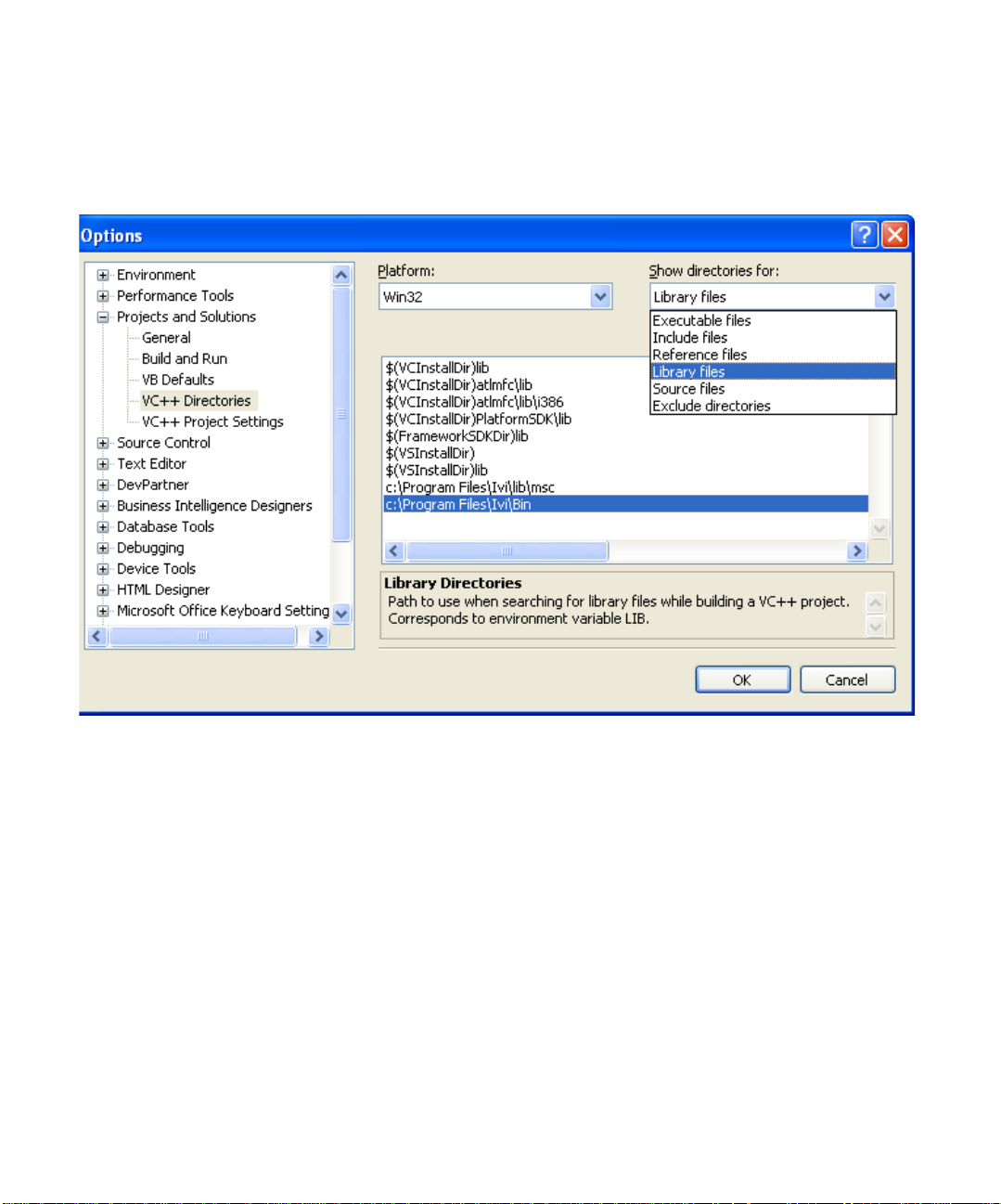
2 From the Tools menu select Options.
3 Expand “Projects and Solutions”, then click on “VC++ Directories”
4 Click on the “Show directories for” combo box and choose “Library files”
5 Add the following two entries to your path.
The first entry will point to the default directory for IVI drivers. This is typically:
“C:\Program Files\Ivi\Bin”
The second entry points to the VISA DLL that many drivers require:
Page 19

Initialize COM
“$(VXIPNPPATH)VisaCom”
Note:
These steps need only be done once for each computer you use. All
subsequent Visual Studio projects will continue to use these settings and will be
able to locate your IVI-COM drivers.
6 Click OK
7 To import the type libraries, type the following statements following the header
file reference:
#import “IviDriverTypeLib.dll” no_namespace
#import “IviDmmTypeLib.dll” no_namespace
#import “GlobMgr.dll” no_namespace
#import “Agilent34401.dll” no_namespace
Note:
The
import
statements access the driver type libraries used by the Agilent
34401 DMM. The no_namespace attribute allows the code to access the interfaces
in the typelibraries from the global namespace.
1 To initialize the COM library, type the following lines after the { following the int
statement:
HRESULT hr;
hr = CoInitialize(NULL);
IF(FAILED(hr))
exit(1);
Note: Including error handling in your programs is good practice. This code
checks for errors in your program.
2 To close the COM library before exiting, type the following line at the end of
your code, right before the return line:
CoUninitialize();
Create an Instance of the Driver
To create an instance of the driver, type
IIviDmmPtr dmm(__uuidof(Agilent34401));
Note:
This creates a smart pointer that provides easy access to the COM object.
You are now ready to write the program to control the simulated instrument.
Using IVI with Visual C++
•
•
•
19
•
•
•
Page 20
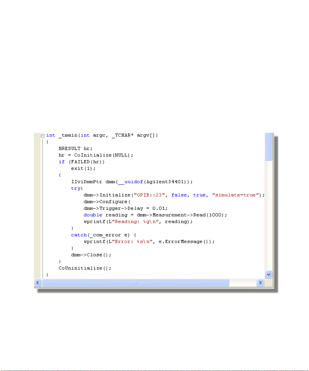
Initialize the Instrument
You can now write the main constructs for your program.
Below the smart pointer statement, type
dmm->Initialize("GPIB::23", false, true, "simulate=true");
Note
: As soon as you type ->, Intellisense displays options and helps ensure you
use correct syntax and values.
Configure the Instrument
To set the range to 1.5 volts and resolution to 0.001 volts, type
dmm->Configure(IviDmmFunctionDCVolts, 1.5, 0.001);
•
•
•
20
Chapter 2
•
•
•
Set the Trigger Delay
To set the trigger delay to 0.01 seconds, type
dmm->Trigger->Delay = 0.01;
Page 21

Set the Reading Timeout/Display the Reading
Create a variable to represent the reading and make a reading with a timeout of 1
second (1000 milliseconds).
1 Type
double reading = dmm->Measurement->Read(1000);
2 To display the reading, use printf. Type
wprintf(L“Reading: %g\n”, reading);
Error Checking
To catch errors in the code, activate error checking.
1 Surround the preceding statement s with a try block. Add the following lines as
shown in the illustration above:
try {
}
2 Process errors in a catch block. Type
catch (_com_error e) {
wprintf(L“Error: %s”, e.ErrorMessage());
}
Close the Session
To close out the instance of the driver and free resources, type
dmm->Close();
The final code should look like the following:
#include "stdafx.h"
#import "IviDriverTypeLib.dll" no_namespace
#import "IviDmmTypeLib.dll" no_namespace
#import "GlobMgr.dll" no_namespace
#import "Agilent34401.dll" no_namespace
int IVI_Demo()
{
HRESULT hr;
hr = CoInitialize(NULL);
if(FAILED(hr))
Using IVI with Visual C++
•
•
•
21
•
•
•
Page 22

exit(1);
{
IAgilent34401Ptr dmm(__uuidof(Agilent34401));
try{
dmm->Initialize("GPIB::23",false,true,"simulate=true");
dmm->DCVoltage->Configure(1.5, 0.001);
dmm->Trigger->Delay = 0.01;
double reading = dmm->Measurement->Read(1000);
wprintf(L“Reading: %g\n”, reading);
}
catch(_com_error e){
wprintf(L“Error: %s\n”, e.ErrorMessage);
}
dmm->Close();
}
CoUninitialize();
return 0;
}
•
•
•
22
Chapter 2
•
•
•
Build and Run the Application
Build your application and run it to verify it works properly.
1 From the Start Menu, select Build, and click Build IVIDemo.
2 From the Start Menu, select Debug, and run the application.
Using IVI-C in Visual C++
The following sections show to get started with IVI-C in Visual C++.
Create a New Project and Import the Driver Type Libraries
To use an IVI-C Driver in a Visual C++ program, you must provide paths to the
header files and libraries it uses.
1 Launch Visual Studio 2005 and create a Win32 Console Application in C++
with the name IVI demo.
Note:
The program already includes some required code, including the header file
#include stdafx.h
.
Page 23

2 From the Tools menu select Options.
3 Expand “Projects and Solutions”, then click on “VC++ Directories”
4 Click on the “Show directories for” combo box and choose “Library files”
5 Add the following entry to your “Library files” path.
This entry points to the default directory for IVI drivers. This is typically:
“C:\Program Files\IVI\Lib\msc”
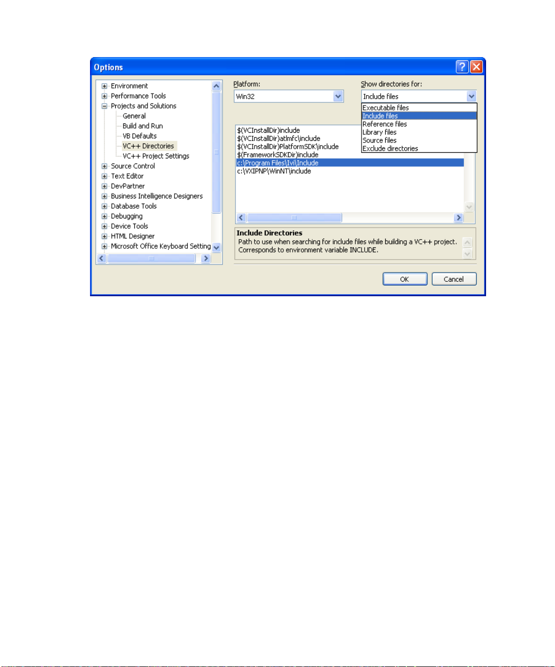
6 Click on the “Show directories for” combo box and choose “Include files”
7 Add the following entries to your “Include files” path.
The first entry will point to the default directory for IVI drivers. This is typically:
“C:\Program Files\IVI\include”
The second entry points to the VISA header files that IVI-C drivers require:
“$(VXIPNPPATH)WinNT\include”
8 Click OK
Note:
These initial steps need only be done once for each computer you use. All
subsequent Visual Studio projects will continue to use these settings and will be
able to locate your IVI-COM drivers.
9 Select Project and click Properties. The IVIDemo.cpp “Property pages” dialog
box appears.
Using IVI with Visual C++
•
•
•
23
•
•
•
Page 24
10 Expand “Configuration Properties”
11 Expand “Linker”
12 Select Input. In the Additional Dependencies field, type
13 Select OK.
14 To add the hp34401a instrument driver header file to your program, type the
15 From the Main Menu, select Build and click Build IVIDemo.
Declare V ariables
1 Y ou will need to declare some variables that will be used in your program. T ype
“hp34401a.lib”
following statement following the existing header file reference:
#include “hp34401a.h”
the following lines after the { in the int main () statement:
ViSession session;
ViStatus error = VI_SUCCESS;
ViReal64 reading;
•
•
•
24
Chapter 2
•
•
•
Page 25

Define Error Checking
1 Next define error checking for your program. First you will define a macro to
catch the errors. It is better to define it once at the beginning of the program
that to add the logic to each of your program statements. After the #include
statements, type the following lines:
#ifndef checkErr
#define checkErr(fCall) \
if (error = (fCall), (error = (error < 0) ? \
error : VI_SUCCESS)) \
{goto Error;} else error = error
#endif
2 Next you will type the following lines at the end of the program to handle any
errors that occur:
Error:
if (error != VI_SUCCESS)
{
ViChar errStr[2048];
hp34401a_GetError (session, &error, 2048, errStr);
printf ("Error!", errStr);
}
Note: Including error handling in your programs is good practice. This code checks
for errors in your program.
Initialize the Instrument
1 To initialize the instrument, add the following Initialize with Options function
right after the variable declarations you added in the previous section
checkErr( hp34401a_InitWithOptions (“GPIB::23::INSTR”,
This initializes the instrument with the following parameters:
• GPIB0::23::INSTR as the Resource Name (instrument at GPIB address 23)
• VI_FALSE Does not perform an ID Query
• VI_TRUE Resets the device
VI_FALSE, VI_TRUE, “Simulate = 1”, &session));
Using IVI with Visual C++
•
•
•
25
•
•
•
Page 26

• Simulate=1 in the Options parameter sets the driver to simulation mode
• &session assigns the Instrument Handle to the variable “session” defined above
Configure the Instrument
1 To set the range to 1.5 volts and resolution to 0.001 millivolts, type:
checkErr( hp34401a_ConfigureMeasurement (session,
HP34401A_VAL_DC_VOLTS, 1.5, 0.001));
Set the Trigger and Trigger Delay
1 To set the trigger source to immediate and the trigger delay to 0.01 seconds,
type:
checkErr( hp34401a_ConfigureTrigger (session,
HP34401A_VAL_IMMEDIATE, 0.01));
Set the Reading Timeout/Display the Reading
1 To take a reading from the instrument and to set the reading timeout to 1
second (1000 ms) type:
checkErr( hp34401a_Read (session, 1000, &reading);
Note: The Read function takes a reading from the instrument and assigns the result
to the variable “reading” defined above.
2 To display the reading, use a pr int f statemen t. Type
printf (“Reading = %f”, reading);
•
•
•
26
Chapter 2
•
•
•
Close the Session
To close out the instance of the driver and free resources, type
If (session)
hp34401a_Close(session);
The final code should contain the code below:
#include "stdafx.h"
#include <hp34401a.h>
#ifndef checkErr
#define checkErr(fCall) \
if (error = (fCall), (error = (error < 0)?
error : VI_SUCCESS)) \
{goto Error;} else error = error
Page 27

#endif
int main(int argc, _TCHAR* argv[])
{
ViSession session;
ViStatus error = VI_SUCCESS;
ViReal64 reading;
checkErr( hp34401a_InitWithOptions ("GPIB::23::INSTR",
VI_FALSE, VI_TRUE, "Simulate=1", &session));
checkErr( hp34401a_ConfigureMeasurement (session,
HP34401A_VAL_DC_VOLTS, 1.5, 0.0001));
checkErr( hp34401a_ConfigureTrigger (session,
HP34401A_VAL_IMMEDIATE, 0.01));
checkErr( hp34401a_Read (session, 1000, &reading));
printf ("Reading = %f", reading);
Error:
if (error != VI_SUCCESS)
{
ViChar errStr[2048];
hp34401a_GetError (session, &error, 2048, errStr);
printf ("Error!", errStr);
}
if (hp34401a)
hp34401a_close (hp34401a);
}
Build and Run the Application
Build your application and run it to verify it works properly.
Using IVI with Visual C++
•
•
•
27
•
•
•
Page 28

1 From the Start Menu, select Build, and click Build IVI Demo.
2 From the Start Menu, select Debug, and run the application.
Further Information
Learn more about Visual C++ at http://msdn.microsfot.com/visualc/.
Microsoft® and Visual Studio® are registered tradem arks of Microsoft Corporation
in the United States and/or other countries.
•
•
•
28
Chapter 2
•
•
•
Page 29

Chapter 3
Using IVI with Visual C# and
Visual Basic .NET
• • • • • •
The Environment
C# and Visual Basic are object-oriented programming languages developed by
Microsoft. They enable programmers to quickly build a wide range of applications
for the Microsoft .NET platform. This chapter provides detailed instructions in C#
as well as the code for Visual Basic.
Visual Basic 6.0, refer to Chapter 9.
Note:
One of the key advantages of using C# and Visual Basic in the Microsoft®
Visual Studio
InstelliSense is a form of autocompletion for variable names and functions and a
convenient way to access parameter lists and ensure correct syntax. The feature
also enhances software development by reducing the amount of keyboard input
required.
Example Requirements
•
Visual C#
•
Microsoft Visual Studio 2005
•
Agilent 34401A IVI-COM, Version 1.1.0.11, March 2006 (from Agilent
Technologies)
•
Agilent IO Libraries Suite 14.2
®
Integrated Development Environment is IntelliSense™.
If you are looking for an example using
Download and Install the Driver
If you have not already installed the driver, go to the vendor W eb site and follow the
instructions to download and install it. You can also refer to Chapter 1, Download
and Install IVI Drivers, for instructions.
This example uses an IVI-COM driver. IVI-COM is the preferred driver for C#, but
IVI-C is also supported.
•
•
•
29
•
•
•
Page 30
Create a New Project and Reference the Driver
To use an IVI Driver in a Visual C# program, you must first add a reference to it.
1 Launch Visual Studio and start a new Console Application in Visual C#.
Note:
The program already includes some required code, including using
statements. Keep this required code.
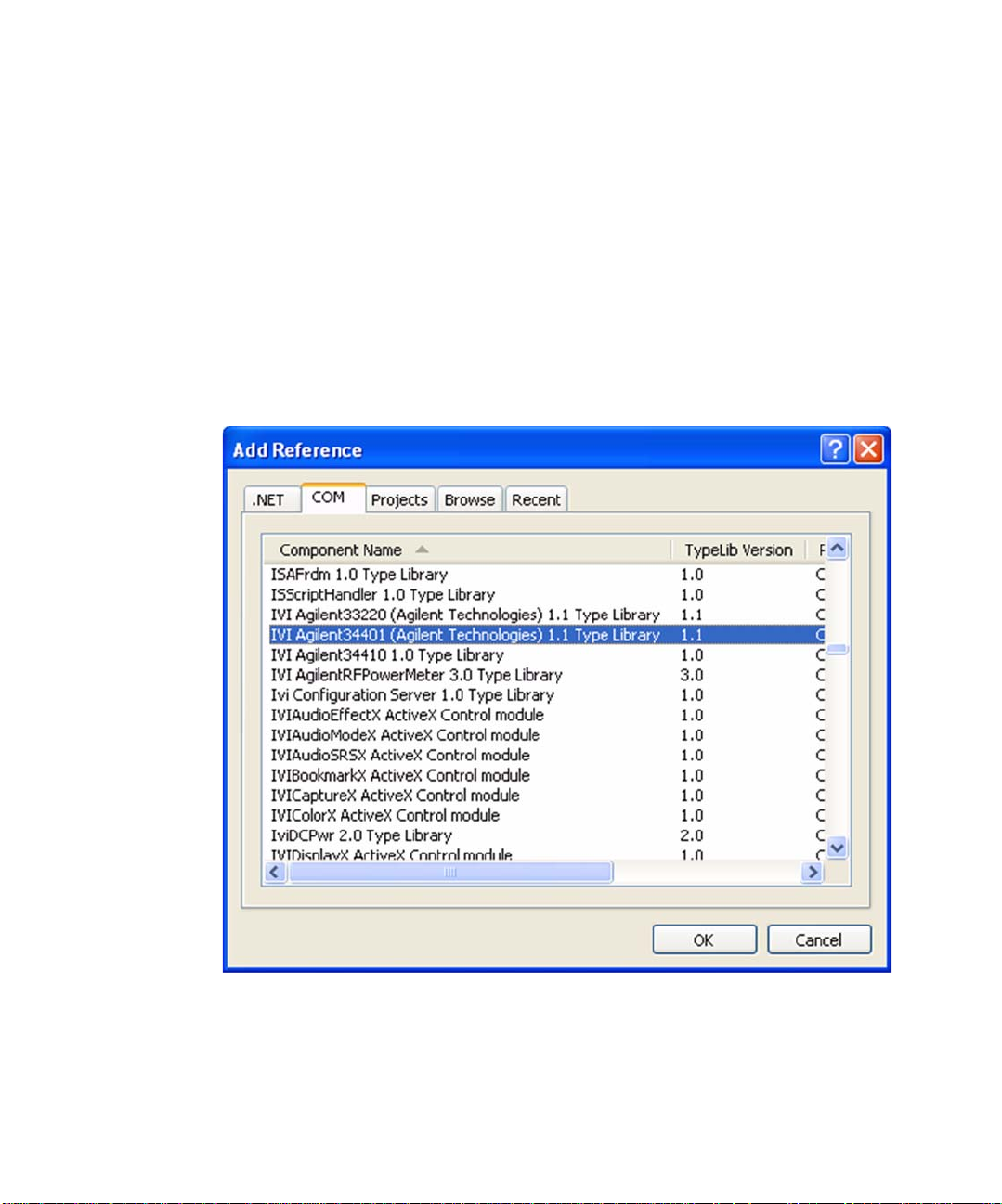
2 Select Project and click Add Reference. The Add Reference dialog appears.
3 Select the COM tab. All IVI drivers begin with IVI. Scroll to the IVI section and
select IVI Agilent 34401 (Agilent Technologies) 1.1 Type Library. Click OK.
Note
: If you have not installed the IVI driver, it will not appear in this list. You must
close the Add Reference dialog, install the driver, and select Add Reference again
for the driver to appear.
•
•
•
30
Chapter 3
•
•
•
Note:
The program looks the same as it did before you added the reference, but
the driver is now available for use. To see the reference, select View and click
Solution Explorer. Solution Explorer appears and lists the reference.
Page 31

Create an Instance of the Driver
T o allow your program to access the driver without specifying the full path, type the
following line immediately below the other
using Agilent.Agilent34401.Interop;
Note:
As soon as you type the A for Agilent, IntelliSense lists the valid inputs.
Congratulations! You may now write the program to control the simulated
instrument.
using
statements:
Note
: T o view the functions and parameters available in the instrument driver , rightclick the library in the References folder in Solution Explorer and select View in
Object Browser.
Using IVI with Visual C# and Visual Basic
•
•
•
31
•
•
•
Page 32

•
•
•
32
Chapter 3
•
•
•
Initialize the Instrument
You can now write the main constructs for your program. Create a variable to
represent your instrument and set the Initialization parameters.
1 Type Agilent34401Class dmm = new Agilent34401Class();
2 Type dmm.Initialize (“GPIB::23”, false, true,
“simulate=true”);
Note
: IntelliSense helps ensure you use correct syntax and values.
Page 33

Configure the Instrument
To set the range to 1.5 volts and the resolution to 1 millivolt, type
dmm.DCVoltage.Configure(1.5, 0.001);
Set the Trigger Delay
To set the trigger delay to 0.01 seconds, type
dmm.Trigger.Delay = 0.01;
Set the Reading Timeout/Display the Reading
Create a variable to represent the reading and display the reading:
1 Type double reading;
2 To trigger the multimeter and take a reading with a timeout of 1 second, type
reading = dmm.Measurement.Read(1000);
3 Type Console.WriteLine("The measurement is {0}", reading);
4 Type Console.ReadLine();
Close the Session
To close out the instance of the driver to free resources, type
dmm.Close();
Using IVI with Visual C# and Visual Basic
•
•
•
33
•
•
•
Page 34

Your final program should contain the code below:
using System;
using System.Collections.Generic;
using System.Text;
using Agilent.Agilent34401.Interop;
namespace ConsoleApplication1
{
class Program
{
static void Main(string[] args)
{
Agilent34401Class dmm = new
Agilent34401Class();
dmm.Initialize("GPIB::23", false, true, "sim-
ulate=true");
dmm.DCVoltage.Configure(1.5, 0.001);
dmm.Trigger.Delay = 0.01;
double reading;
reading = dmm.Measurement.Read(1000);
Console.WriteLine("The measurement is {0}",
reading);
Console.ReadLine();
dmm.Close();
}
}
}
•
•
•
34
Chapter 3
•
•
•
Build and Run the Application
Build your application and run it to verify it works properly.
1 From the Build menu, click the name of your Console Application.
2 From the Debug menu, click Start Debugging.
Tips
The code for a Visual Basic console application in Visual Studio 2005 is almost
identical to the C# application:
Option Explicit On
Page 35

Imports Agilent.Agilent34401.Interop
Module Module1
Sub Main()
Dim dmm As New Agilent34401
dmm.Initialize("GPIB::23", False, True,
"simulate=true")
dmm.Function =
Agilent34401FunctionEnum.Agilent34401FunctionDCVolts
dmm.DCVoltage.Configure(1.5, 0.001)
dmm.Trigger.Delay = 0.01
End Module
The main differences include the following:
•
•
•
•
Further Information
•
•
Console.WriteLine(“The reading is {0}”, reading)
Console.ReadLine()
End Sub
To use Visual Basic, select Visual Basic in Project Types.
To enforce type checking, insert a line at the start of the code. Type
Option Explicit On
To call the DCVolts function you need to insert a line of code. Type
dmm.Function =
Agilent34401FunctionEnum.Agilent34401FunctionDCVolts
To dimension a variable for the instrument and reading, use
reading
Learn more about Visual C# at http://msdn.microsoft.com/vsharp/.
Learn more about Visual Basic at http://msdn.microsoft.com/vbasic/.
Dim reading As New Double
reading = dmm.Measurement.Read(1000)
dmm.Close()
Dim dmm
.
and
Dim
Microsoft® and Visual Studio® are registered tradem arks of Microsoft Corporation
in the United States and/or other countries.
Using IVI with Visual C# and Visual Basic
•
•
•
35
•
•
•
Page 36

•
•
•
36
Chapter 3
•
•
•
Page 37

Chapter 4
Using IVI with LabVIEW
• • • • • •
The Environment
National Instruments LabVIEW is a graphical development environment for signal
acquisition, measurement analysis, and data presentation. LabVIEW provides the
flexibility of a programming language with less complexity than traditional
development tools.
Example Requirements
•
LabVIEW 8.2.0
•
IVI-C: Agilent 34401A IVI-C specific driver, Version 4.1, October 2006 (from
National Instruments)
•
IVI-COM: Agilent 34401A IVI-COM driver, Version 1.1.0.11, March 2006 (from
Agilent Technologies)
Note:
These drivers may require an I/O library to be installed. Check the driver
vendor’s Web site for details.
Download and Install the Driver
If you have not already installed the driver, go to the vendor Web site and follow
the instructions to download and install it.
Since LabVIEW supports both IVI-C and IVI-COM drivers, this example is written
two ways, first to show how to use an IVI-C driver in LabVIEW, and second how to
use an IVI-COM driver in LabVIEW.
TM
Using IVI-C
Note:
The functionality shown in the example is available in a LabVIEW example
supplied with the IVI driver from National Instruments.
Alll IVI-C drivers provide a Dynamic Link LIbrary (DLL) interface. While LabVIEW
provides the Call Library Function node to call DLLs, many IVI-C drivers also come
with a LabVIEW wrapper that provides the familiar VI interface to the driver’s
•
•
•
37
•
•
•
Page 38

functions, making it easier to use in LabVIEW. If your IVI-C driver does not have a
LabVIEW wrapper, you can create one using a free tool by clicking on
Instrument Driver Import Wizard at
http://www.ni.com/devzone/idnet/development.htm
Note:
The functionality shown in this section is available in a LabVIEW example
supplied with the IVI driver from National Instruments.
Create a Project and Access the Driver
1 Launch LabVIEW.
2 From the File menu, select New VI. The Front Panel and Block Diagram
appear.
3 Right-click in the Block Diagram. The Functions palette appears.
4 Select the Instrument I/O subpalette and then the Instrument Drivers
subpallete. You can access all instrument driver VIs from this palette.
5 Click Instrument Drivers. Select hp34401a from the palette.
6 Select the hp34401a IVI driver from the palette.
Note
: If the driver you want to use is not listed, download and install the driver, and
close and restart LabVIEW. The driver should now appear in the palette. The driver
palette allows you to browse the various VIs and functionality
driver.
LabVIEW
:
supported by the
•
•
•
38
Chapter 4
•
•
•
Page 39

Initialize the Instrument
1 Select Initialize With Options VI from the hp34401a palette and place it on the
Block Diagram.
2 Create constants and enter values for instrument resource nam e, ID Query,
Reset, and IVI option string:
•
GPIB0::23::INSTR
•
False
in the ID Query field
•
True
in the Reset field
•
Simulate=1
Note:
To create a constant, control, or indicator, right-click on the desired input
terminal and select Create.
in the instrument resource name field
in the Options field
Using IVI with LabVIEWTM 39
•
•
•
•
•
•
Page 40

Configure the Instrument
1 From the Configuration subpalette, select Configure Measurement VI and
place it on the Block Diagram.
2 Create constants and enter values to set the resolution to 1 millivolt, the
function to DC Voltage, and the range to 1.5 volts:
•
0.001
•
DC volts
•
1.5
in the Range field
3 Connect the instrument handle and error terminals from Initialize With Options
VI to Configure Measurement VI.
4 From the Trigger subpalette, select Configure Trigger VI and place it on the
Block Diagram.
5 Connect resource name and error information from Con figure Measurement VI
to Configure Trigger VI.
6 Create a constant and enter a value of 0.01 in the Trigger Delay field.
Note:
You can also set the T r igger Delay using a Property Node by replacing steps
4 & 5 with a property access as shown in the section “Setting a Property in an IVIC Driver” below.
in the Resolution field
in the Measurement Function field
•
•
•
40
Chapter 4
•
•
•
Take the Reading
1 Return to the main hp34401a palette. From the Measurement subpalette,
select Read VI and place it on the Block Diagram.
2 Set the value for Timeout to 1 second (1000 ms). Enter 1000 in the Timeout
field.
Page 41

3 Connect resource name and error information from Configure T ri gger to Read
VI.
Display the Reading
Create an indicator for Reading from the terminal on the Read VI.
Close the Session
1 Return to the main hp 34401a palette. Select Close VI and place it on the Block
Diagram.
2 Connect resource name and error information from Read VI to Close VI.
Note:
execution at any time.
Add Error Checking
1 Return to the main functions palette. From the Dialog & User Interface
subpalette select Simple Error Handler VI and place it on the Block Diagram.
2 Connect the error information from Close VI to Simple Error Handler VI.
Run the Application
Y our final VI Block Diagram should cont ain the elements shown below . To run your
VI:
1 Switch to the VI’s Front Panel and click on the Run arrow to run the application.
2 The Reading indicator should display a simulated reading from the instrument.
LabVIEW compiles while developing, which lets you check the program
•
•
Using IVI with LabVIEWTM 41
•
•
•
•
Page 42

Setting a Property in an IVI-C Driver
Properties such as Trigger Delay can also be set (and read) with a property node.
This is important in cases where a configuration function is not provided by the
driver.
For example we can replace steps 4 and 5 of the “Configure the Instrument”
section with:
1 From the Functions palette select Application Control and drop a Property
Node on the Block Diagram.
2 Connect the resource name and error information from Configure
Measurement VI to the Property Node.
3 Right-click on the Property Node and select Change All to Write.
4 Click on the Property field and select Trigger >> Trigger Delay.
•
•
•
42
Chapter 4
•
•
•
Using IVI-COM
To use IVI-COM drivers in LabVIEW you will use the ActiveX functions and the
Class Browser that are built-in to LabVIEW.
Create a Project and Access the Driver
1 Launch LabVIEW
Page 43

2 From the File menu, select New VI. The Front Panel and Block Diagram
appear.
3 Right-click in the Block Diagram. The Functions palette appears.
4 Select the Connectivity subpalette and then the Active X subp alle te. From this
palette, you can access ActiveX and COM objects including all IVI-COM
drivers.
5 Select Automation Open from the palette and place it on the block diagram.
6 Right-click on the Automation Refnum terminal, select Select ActiveX Class...
and then Browse...
Using IVI with LabVIEWTM 43
•
•
•
•
•
•
Page 44

7 From the Type Library drop-down, select the IVI Agilent 34401A (Agilent
Technologies) 1.1 Type Library Version 1.1, and then select the IAgilent34401
object. Click OK.
Note:
If the IVI-COM driver you want to use is not listed, download and install the
driver and close and restart LabVIEW. The driver should now appear in the type
library browser.
•
•
•
44
Chapter 4
•
•
•
Initialize the Instrument
1 From the View menu, select Class Browser. The Class Browser allows you to
invoke methods and set or get properties of the ActiveX/COM object.
2 From the Object library drop-down, select ActiveX and then Select Type
Libraries.
3 Scroll down and select the IVI Agilent 34401A (Agilent Technologies) 1.1 T ype
Library Version 1.1, Click OK.
Page 45

4 Back in the Class Browser, under Properties and Methods, scroll down and
select Initialize. Click Create and drag the Invoke Node to the Block Diagram.
5 Create constants and enter values for ResourceName, IDQuery, Reset, and
OptionString:
•
GPIB0::23::INSTR
•
False
in the IDQuery field
•
True
in the Reset field
•
Simulate=1
in the instrument ResourceName field
in the OptionString field
6 Connect the automation refnum and error terminals from Automation Open to
Initialize Invoke Node.
Note:
Instead of using the Class Browser, you can select an Invoke Node from the
ActiveX subpalette and select the Initialize method. To access driver properties,
you can select a Property Node from the ActiveX subpalette and select the
appropriate property or you can use the Class Browser for both IVI-C and IVI-COM
drivers.
Configure the Instrument
1 Go back to the Class Browser, and under Properties and Methods, double-
click the DC Voltage property and select the Configure method. Click Create
and drag the Invoke Node to the Block Diagram.
2 Create constants and enter values to set the Resolution to 1 millivolt and the
Range to 1.5 volts:
•
0.001
•
1.5
in the Range field
in the Resolution field
•
•
Using IVI with LabVIEWTM 45
•
•
•
•
Page 46

3 Connect the automation refnum and error terminals from Initialize Invoke Node
to DCVoltage.Configure Invo ke Node.
4 In the Class Browser, go back to the top-level object and double-click the
Trigger property and select the Delay property . Click Create Write and drag the
Property Node to the Block Diagram.
5 Create a constant and enter a value of 0.01 seconds for the Delay field.
6 Connect the automation refnum and error terminals from DCV oltage.Configure
Invoke Node to Trigger.Delay Property Node.
Take the Reading
1 Return to the Class Browser , and under Properties an d Methods, doub le-click
the Measurement property and select the Read method. Click Create and drag
the Invoke Node to the Block Diagram.
2 Set the value for Timeout to 1 second (1000 ms) by entering 1000 in the
MaxTimeMilliseconds field.
3 Connect the automation refnum and error terminals from Trigger.Delay
Property Node to Measurement.Read Invoke Node.
Display the Reading
Create an indicator for Measurement.Read from the Invoke Node terminal.
•
•
•
46
Chapter 4
•
•
•
Close the Driver and Automation Sessions
1 Return to the Class Browser , and under Properties an d Methods, doub le-click
the Close method. Click Create and drag the Invoke Node to the Block
Diagram.
2 Close the Class Browser. From the ActiveX subpalette, select Close
Reference and place on the Block Diagram.
3 Connect the automation refnum and error terminals from Measuremen t.Read
Invoke Node to Close Invoke Node and then to Close Reference function.
Add Error Checking
1 Return to the main functions palette. From the Dialog & User Interface
subpalette select Simple Error Handler VI and place it on the Block Diagram.
2 Connect the error information from Close Reference function to Simple Error
Handler VI.
Page 47

Run the Application
Y our final VI Block Diagram should cont ain the elements shown below . To run your
VI:
1 Switch to the VI’s Front Panel and click on the Run arrow to run the application.
2 The Reading indicator should display a simulated reading from the instrument.
Further Information
Learn more about using an instrument driver in LabVIEW in this tutorial:
http://zone.ni.com/devzone/cda/tut/p/id/2804
.
•
•
Using IVI with LabVIEWTM 47
•
•
•
•
Page 48

•
•
•
48
Chapter 4
•
•
•
Page 49

Chapter 5
Using IVI with LabWindowsTM/CVI
• • • • • •
The Environment
National Instruments LabWindows/CVI is an ANSI-C integrated development
environment that provides a comprehensive set of programming tools for creating
test and control applications. LabWindows/CVI combines the longevity and
reusability of ANSI-C with engineering-specific functionality designed for
instrument control, data acquisition, analysis, and user interface development.
Example Requirements
•
LabWindows/CVI 8.1
•
Agilent 34401A IVI-C specific driver, Version 4.1, October 2006 (from National
Instruments)
Download and Install the Driver
If you have not already installed the driver, go to the vendor W eb site and follow the
instructions to download and install it. You can also refer to Chapter 1, Download
and Install IVI Drivers, for instructions.
This example uses an IVI-C driver. IVI-C is the preferred driver for
LabWindows/CVI.
TM
Create a New Project and Add Instrument Driver Files
1 Launch LabWindows/CVI.
2 Select File, select New, and click Project.
3 To create a new C source file, select New and click Source (*.c). Save the file.
4 Select Edit and click on Add Files to Project to add the C source file to your
project.
5 Select Edit and click on Add Files To Project to add one of the following
instrument driver files to your project: hp34401a.fp, hp34401a.c, or
hp34401a.lib.
•
•
•
49
•
•
•
Page 50

•
•
•
50
Chapter 5
•
•
•
Note: Any of the three files listed above will work. Adding one of the HP 34401A
instrument driver files loads that instrument driver. View the available functions
in the library tree in the workspace window.
6 Add the following line to your program to include the instrument driver header
file:
#include “hp34401a.h”
Initialize the Instrument
1 From the Edit menu, select Insert Construct, and click Main.
2 Find the hp34401a instrument driver in the instrument driver tree. Select
Initialize with Options from the library tree. The Initialize with Options function
panel opens.
3 Enter values for Resource Name, ID Query, Reset Device, and Option String:
•
GPIB0::23::INSTR
•
No
•
Yes
•
Simulate=1
Note:
automatically. The options are enabled by default.
in the Resource Name field
for ID Query control
for Reset Device control
in the Options field
The RangeCheck, QueryInstrStatus, and Cache options appear
Page 51

4 Select the Instrument Handle parameter. From the Code Menu, click Declare
Variable to set the Instrument Handle parameter.
5 Enter session in the Variable Name field.
6 Check the boxes titled Execute declaration in Interactive Window and Add
declaration to top of target file “*.c”. Click OK.
Note: T o test the function with the specified p arameter values, select Code and
click Run Function Panel or click the run button in the toolbar to operate the
function panel interactively.
7 From the Code Menu, click Insert Function Call to insert the function and
values into your program. Close the function panel. The
hp34401a_InitWithOptions function appears in your program.
Using IVI w ith LabW indow sTM/CV ITM
•
•
•
51
•
•
•
Page 52

Configure the Instrument
1 From the library tree, select Configuration and click ConfigureMeasurement.
The ConfigureMeasurement function panel opens.
2 Set the function to DC Voltage, range to 1.5 volt s, resolution to 1 millivolt, and
instrument handle to session. Select and enter:
•
DC Volts
•
1.5
in the Range field,
•
0.001
•
session
from the drop-down list in the Measurement Function field,
in the Resolution field, and
in the Instrument Handle field.
•
•
•
52
Chapter 5
•
•
•
Page 53

3 Select the Code menu and click Insert Function Call to insert the function and
values into your program. Close the function panel. The
hp34401a_ConfigureMeasurement function appears in your program.
4 From the library tree, select Configuration, select Trigger, and click
ConfigureTrigger. The Configure Trigger function panel opens.
5 Set the trigger source to immediate, the trigger delay to 0.01 seconds, and the
instrument handle to session. Select and enter:
•
Immediate
•
0.01
in the Trigger Delay field
•
session
6 Select Code and click Insert Function Call to insert the function and values into
your program. Close the function panel. The hp34401a_ConfigureTrigger
function appears in your program.
Set the Reading Timeout
1 From the library tree, select Measurement and click Read. The Read dialog
opens.
2 Set the value for Timeout to 1 second (1000 ms), and instrument handle to
session. Enter:
•
1000
from the drop-down list in the Trigger Source field
in the Instrument Handle field
in the Read field
Using IVI w ith LabW indow sTM/CV ITM
•
•
•
53
•
•
•
Page 54

•
session
Display the Reading
1 Select the Reading parameter.
2 Select Code and click Declare Variable. The Declare Variable dialog appears.
3 Enter reading in the Variable Name field.
4 Check the boxes titled Execute declaration in Interactive Window and Add
declaration to top of target file “*.c”. Click OK.
5 Select Code and click Insert Function Call to insert the function and values into
your program. Close the function panel. The hp34401 a_Read function appears
in your program.
Close the Session
1 From the library tree, select Close. The Close function panel opens.
2 Enter session in the Instrument Handle field.
3 Select Code and click Insert Function Call to insert the function and values into
your program. Close the function panel. The hp34401a_Close function
appears in your program. Your final program should contain the code below:
in the Instrument Handle field
#include <ansi_c.h>
#include "hp34401a.h"
#include <cvirte.h>
static ViReal64 reading;
static ViSession session;
•
•
•
54
Chapter 5
•
•
•
int main (int argc, char *argv[])
{
if (InitCVIRTE (0, argv, 0) == 0)
return -1; /* out of memory */
hp34401a_InitWithOptions (
"GPIB0::23::INSTR", VI_FALSE,
VI_TRUE, "Simulate=1", &session);
hp34401a_ConfigureMeasurement (session,
HP34401A_VAL_DC_VOLTS, 1.5, 0.001);
hp34401a_ConfigureTrigger (session,
HP34401A_VAL_IMMEDIATE, 0.01);
hp34401a_Read (session, 1000, &reading);
printf ("%f", reading);
hp34401a_close (session);
return 0;
}
Note:
T o display the reading, add a printf function. Before the Close function, type:
Page 55

printf (“%f”, reading);
Note:
CheckErr macro provided in the ivi.h file to handle errors. See the example
included with the hp34401 downloaded driver for error handling demonstration
code.
Further Information
Learn more about LabWindows/CVI at http://www.ni.com/lwcvi/.
The mark LabWindows is used under a license from Microsoft Corporation
Including error checking in your programs is good practice. Use the
Using IVI w ith LabW indow sTM/CV ITM
•
•
•
55
•
•
•
Page 56

•
•
•
56
Chapter 5
•
•
•
Page 57

Chapter 6
Using IVI with MATLAB
• • • • • •
The Development Environment
MATLAB from The MathWorks is an interactive software environment for data
acquisition and analysis, waveform generation, algorithm creation, and test system
development. MATLAB also provides a technical computing language that is
designed to help you solve technical challenges faster than with traditional
software environments.
MA TLAB supports IVI instrument drivers using the Instrument Control T oolbox. The
toolbox provides additional MATLAB functionality.
Example Requirements
•
MATLAB R2007a
•
MATLAB Instrument Control Toolbox
•
Agilent 34401A IVI-COM, Version 1.1.0.11, March 2006 (from Agilent
Technologies)
•
Agilent IO Libraries Suite 14.2
Download and Install the Driver
If you have not already installed the driver, go to the vendor W eb site and follow the
instructions to download and install it.
®
This example uses an IVI-COM driver, MATLAB also supports IVI-C drivers.
Note:
Older versions of the Instrument Control T oolbox (R2006b or earlier) support
only IVI instrument drivers that used the IDispatch interface. IVI instrument drivers
that use the IUknown interface only will not work with these versions. To determine
if the driver implements only the IUknown interface, please consult the vendor.
•
•
•
57
•
•
•
Page 58

Configure the IVI Driver
The Instrument Control T oolbox provides a graphical Test & Measurement Tool that
enables you to interact with instrument drivers and instruments without writing
MATLAB code. The Test & Measurement Tool lets you configure IVI driver
properties in MATLAB and store them in the IVI configuration store.
Note:
Learn more about the IVI configuration store in Chapter 11 – Advanced
Topics.
1 At the MATLAB command line, type tmtool to launch the Test &
Measurement Tool GUI. Or from the MATLAB Main Menu, select Instrument
Control Toolbox and click Test & Measurement Tool. The T e st & Measurement
Tool GUI opens.
2 In the tree at left, click the IVI node under the Instrument Drivers node.
3 Select the Hardware Assets tab. In the Hardware Asset s dialog, select Add and
enter the following:
•
myDMM
•
This is my Agilent 34401 Digital Multimeter
•
GPIB0::23
in the Name field
in the Description field (optional)
in the IO Resource name field
•
•
•
58
Chapter 6
•
•
•
4 Select the Software Modules tab. The installed IVI drivers appear.
Note:
If you have not installed the IVI driver , it will not appear in this list. You must
close MATLAB, install the driver, and restart MATLAB for the driver to appear.
5 Select Agilent34401 from the drop-down list. The Software Modules dialog lists
the module name, supported instrument models, and description.
Page 59

Next, you must define your Driver Session to link the Software Module with the
Hardware Asset and indicate whether you want to use Simulation Mode or other
optional parameters when connecting.
6 Select the Driver Sessions tab. In the Driver Sessions dialog, select Add and
enter the following:
•
DMM
in the Name field
•
This session matches the Agilent 34401 driver with the hardware asset of
GPIB0::23, and turns on Simulation mode of the driver
in the Description
field (optional)
7 Select Agilent34401 in the Software module drop-down list.
8 Select myDMM in the Hardware asset drop-down list.
9 Check Simulate in the options.
Using IVI with MA TLAB®
•
•
•
59
•
•
•
Page 60

10 Select the Logical Names tab. In the Logical Names dialog, select Add and
enter the following:
•
DMM
in the Name field
•
This logical name enables your program to access any DMM independent
of manufacturer or hardware asset
•
DMM
in the Driver session field
in the Description field (optional)
•
•
•
60
Chapter 6
•
•
•
Page 61

11 Select File and Save IVI Configuration Store. Saving to the store may take
several moments.
12 Close the Test & Measurement Tool.
Generate an Instrument Wrapper
We will now automatically generate an instrument driver wrapper file (.mdd) so that
MATLAB can use the IVI driver.
At the MATLAB command prompt, type
makemid(‘dmm’);
The file
wrapper created by the
communicate with your instrument through an IVI driver.
Note: To help you learn the structure of a driver faster, MATLAB provides
autocompletion support. As you are typing your commands for a driver, press
the Tab key to get a selection of possible completions. You can also use the
command “get” to see a list of possible properties and “methods” to get a list
of methods on the object. “methodsview” will give you a graphical display of
the methods also.
dmm.mdd
appears in the current directory window. This is the instrument
makemid
Configure and Control the Instrument
You can interact with the instrument by using the Test & Measurement T ool or the
MATLAB command line. We use the MATLAB command line here.
Note:
All MATLAB methods and properties are available at the command line.
Create an Instance of the Instrument
To create an instance of the instrument, type
myDmm = icdevice(‘dmm’);
Connect to the Instrument
Similar to the Initialize command in most ADEs, the Connect command in MA TLAB
initializes the instrument. The instrument will be initialized with the properties you
specified using the Test & Measurement Tool. Type
command. You may now use MATLAB to
connect(myDmm);
Configure the Instrument
To set a range of 1.5 volts and resolution of 0.001 volts, type
myDmm.Range = 1.5;
myDmm.Resolution = 0.001;
Using IVI with MA TLAB®
•
•
•
61
•
•
•
Page 62

Set the Trigger Delay
To set the trigger delay to 0.01 seconds, type
myDmm.Trigger.Delay = 0.01;
Set Reading Timeout
To take a reading with a timeout of 1 second, type
myDmm.Timeout = 0.01;
Display Reading
To display the reading, type
data = invoke(myDmm.Measurement,'Read',1000)
Disconnect from the Instrument
Similar to the Close() command in most ADEs, the Disconnect command in
MATLAB closes the instrument. To disconnect, type
disconnect(myDmm);
Remove the Driver from Memory
To remove any reference to the driver from memory, type
delete(myDmm);
•
•
•
62
Chapter 6
•
•
•
Your final application should contain the code below:
>> myDmm = icdevice('dmm');
>> connect(myDmm)
>> myDmm.Range = 1.5;
>> myDmm.Resolution = 0.001;
>> myDmm.Trigger.Delay = 0.01;
>> myDmm.Timeout = 0.01;
>> data = invoke(myDmm.Measurement,'Read',1000)
data =
0.5116
>> disconnect(myDmm);
>> delete(myDmm);
Page 63

Further Information
To learn more about using MATLAB with IVI instrument drivers, visit:
http://www.mathworks.com/ivi
MATLAB is a registered trademark of The MathWorks, Inc.
Using IVI with MA TLAB®
•
•
•
63
•
•
•
Page 64

•
•
•
64
Chapter 6
•
•
•
Page 65

Chapter 7
Using IVI with Measure Foundry
• • • • • •
The Environment
Measure Foundry is a visual software environment for creating test and
measurement, control, and analysis applications. The design environment consists
of forms and the foundry window. You choose components from the foundry
window and drop them onto your form. Clicking on the components accesses
property pages where you can set design, configuration, and connectivity. This
enables fast application development.
Each application consists of three primary elements:
•
a data source supplies data to the application
•
a control source determines how and when the data is used
•
a data sink receives data to process or display
Example Requirements
•
Measure Foundry 5
•
Agilent 34401A IVI-COM, Version 1.1.0.11, March 2006 (from Agilent
Technologies)
•
Agilent IO Libraries Suite 14.2
®
Download and Install the Driver
If you have not already installed the driver, go to the vendor Web site and follow
the instructions to download and install it. You can also refer to Chapter 1,
Download and Install IVI Drivers.
This example uses an IVI-COM driver. IVI-COM is the preferred driver for Measure
Foundry. IVI-C is not supported.
Note
: You cannot specify an instrument in Measure Foundry unless you have
already installed the appropriate driver. If you need to download a nd install a driver ,
you do not need to exit Measure Foundry . Install the driver and it appears in the list
of available devices.
•
•
•
65
•
•
•
Page 66

Data Source
The property pages contain all the information necessary to create an instance of
the driver, initialize and configure the instrument, set the trigger delay and reading
timeout, and close the instrument.
1 Launch Measure Foundry.
2 Select File and Click New. The New Project screen opens.
3 In the Foundry window, select All Components. Enter IVI in the Search field.
4 Select the LXI IVI Dmm component, drag it to the Form, and drop it.
•
•
•
66
Chapter 7
•
•
•
5 Double-click the LXI component. The Properties dialog appears.
Note
: The Properties dialog lets you access functions based on the purpose of
your test.
6 Configure the IVI DMM. To initialize the DMM and set the range to 1.5 volts a nd
resolution to 1 millivolt, enter the following In the Properties dialog:
•
IVI Dmm
in the IVI DMM panel field
Page 67

•
Agilent34401
•
GPIB
and
•
DCV
in the measurement mode field
•
1.5
in the range field
•
0.001
in the resolution field
Note:
Capabilities that are unavailable are grayed out.
7 Click Next.
in the device type field
23
in the VISA connect string field
8 Configure the operating mode. Select Auto refresh and enter 1000 in the
update rate field.
Using IVI with Measure Foundry®
•
•
•
67
•
•
•
Page 68

9 Click Next.
10 Configure the trigger delay. In the Properties dialog, enter 0.01 in the trigger
11 Click Next.
12 Configure the option string, reset, and reading timeout to 1 second. In the
13 Click Next.
Control Source
1 In the Foundry window, select Application Control. Drag and drop the Control
2 Double-click the Control Button. The Properties of Control Button dialog
3 Enter Start/Stop in the text field.
4 Select the switch button type and click Next.
5 Scroll the list of Available items for the IVI Dmm and click Actions.
6 Select Actions and click the double arrow to add to Item sequence.
7 Select Start autorefresh from the drop-down list in Active value.
8 Select Stop autorefresh from the drop-down list in Passive value.
delay field and Immediate in the trigger source field.
Properties dialog, enter the following:
•
Simulate=true
•
1000
in the timeout field
•
Check the Reset on Connect box
The property pages contain the information necessary to label the button and
specify how it controls the program.
Button to the form.
appears.
in the IVI connect option string
•
•
•
68
Chapter 7
•
•
•
Page 69

Using IVI with Measure Foundry®
•
•
•
69
•
•
•
Page 70

Data Sink
The property pages contain all the information necessary to display the output.
1 In the Foundry window , select Display Compone nts. Drag an d drop the Single
Value Label onto the form.
2 Double-click the Single Value Label. The Properties of Single Value Label
dialog appears.
3 Scroll the list of Data sources and click Form:ivi2_IVI Dmm.
4 Check the box by DCV in the Channels field.
•
•
•
70
Chapter 7
•
•
•
Compile and Run
The final program contains the IVC Dmm LXI component (data source), Start/Stop
button (control source), and Single Value Label (data sink). From the Start Menu,
click Compile and Run to check that your program runs.
Close Session
To close the session and release the driver, either exit the program or program a
Control Button to set the Disconnect property to true in the IVI DMM component.
Further Information
Learn more about the Measure Foundry at http://www.measurefoundry.com.
Page 71

DT Measure Foundry® is a registered trademark of Data Tr anslation® in the United
States and/or other countries.
Using IVI with Measure Foundry®
•
•
•
71
•
•
•
Page 72

•
•
•
72
Chapter 7
•
•
•
Page 73

Chapter 8
Using IVI with PAWS
• • • • • •
The Environment
P A WS Developer's Studio gives you the capability to edit, compile, modify , debug,
document, execute, and simulate the test procedures developed in Abbreviated
Test Language for All Systems (ATLAS) in the Windows NT/2000/XP Platform
environment. PAWS supports a full range of the most commonly used ATLAS
Language subsets. A PAWS Toolkit can modify the ATLAS Language subset to
meet a particular Automatic Test Equipment (A TE) configuration. It s output can be
executed on the associated Debugging PAWS/RTS run-time system or can be
translated to run on your unique run-time system.
Creation of a PAWS project typically consists of three main steps:
•
Prepare the PAWS environment
•
Connect to the instrument driver
•
Prepare the run-time system environment and run the project
Example Requirements
•
TYX PAWS Studio 1.34.6
•
Microsoft Visual Studio
•
Agilent 34401A IVI-COM, Version 1.1.0.11, March 2006 (from Agilent
Technologies)
•
Agilent IO Libraries Suite 14.2
Download and Install the Driver
If you have not already installed the driver, go to the vendor Web site and follow
the instructions to download and install it. You can also refer to Chapter 1,
Download and Install IVI Drivers, for instructions.
This example uses an IVI-COM driver. PAWS supports both IVI-COM and IVI-C
drivers.
Note
: If you do not install the appropriate instrument driver , the project will not build
because the referenced files are not included in the program. If you need to
•
•
•
73
•
•
•
Page 74

download and install a driver, you do not need to exit PAWS Studio. Install the
driver and continue with your program.
Prepare the PAWS Environment
To use an IVI Driver in PAWS, you must first prepare the PAWS environment.
1 Launch PAWS Studio and create a new project. In the New PAWS Project
dialog, enter a project name and directory for the project. Click OK.
2 T o add a new file to the A TLAS Project Module, from the Main Menu select F ile
and click New File. The New dialog appears.
3 Select ATLAS file. Check the option to add the file to the project.
4 Enter atlas in the File Name field. Click OK. The atlas.atl file appears.
•
•
•
74
Chapter 8
•
•
•
5 Insert the following code in the atlas.atl file and save it:
001000 BEGIN, ATLAS PROGRAM 'IVI-COM DMM' $
001010 REQUIRE, 'DMM-DC-VOLTS', SENSOR(VOLTAGE), DC SIGNAL,
CONTROL, VOLTAGE RANGE -300 V TO 300 V,
MAX-TIME RANGE 1 SEC TO 5 SEC,
CNX HI LO $
Page 75

C$
001110 DECLARE, VARIABLE, 'MEASURED' IS DECIMAL $
C$
E02000 OUTPUT, C'\LF\ATLAS PROGRAM STARTS HERE\LF\' $
C$
002200 VERIFY, (VOLTAGE INTO 'MEASURED'),
DC SIGNAL USING 'DMM-DC-VOLTS',
NOM 0 V UL 0.5 V LL -0.5 V,
VOLTAGE RANGE -0.5 V TO 0.5 V,
MAX-TIME 5 SEC,
CNX HI X20-2 LO X20-3 $
002300 OUTPUT, C'DC VOLT MEASUREMENT 1 = ', 'MEASURED', C'
VDC' $
C$
999000 OUTPUT, C'\LF\ATLAS PROGRAM ENDS HERE\LF\' $
C$
999999 TERMINATE, ATLAS PROGRAM 'IVI-COM DMM' $
6 To add a Device Database Module, from the Main Menu select File and click
New Module.
7 Select DEVICEDB and click OK.
8 T o add a new file to the DEVICEDB Project Module, from the Main Menu select
File and click New File. The New dialog appears.
9 Select DEVICE file. Check the option to add the file to the project.
10 Enter dmm in the File Name field. Click OK.
11 In the PAWS Project window, select the file dmm.ddb.
12 Insert the following code in the dmm.dbb file and save it:
begin dev DMM;
cnx hi DMM-Hi, lo DMM-Lo;
begin FNC = 101; ** DC Voltage Measurement
sensor(voltage)dc signal;
control
Using IVI with PA WS
•
•
•
75
•
•
•
Page 76

{
voltage range -300 v to 300 v continuous;
}
end; ** DC Voltage Measurement
end; *end dmm
Note:
To understand the file contents, refer to the Paws Studio online help.
13 To build the project, from the Main Menu select Build and click Rebuild All.
Add the WCEM Interface Functions
The WCEM interface C++ functions are invoked by the ATLAS code. These C++
functions include the IVI-COM calls to control the instrument.
1 From the Main Menu, select File and click New Module. The New dialog
appears.
2 Select CEM and enter WCEM in the Module Name field. Click OK.
3 From the Main Menu, select View and click CEM Wizard. The CEM Wizard
dialog appears.
4 Click on the Advanced tab. The CEM Wizard Advanced Settings dialog
appears.
5 Check Open, Unload and Disable CEM Logging. Click OK. The CEM Wizard
dialog appears.
6 Right-click on DMM and click on Add Interface Function. The Add Function(s)
to Action(s) dialog appears.
7 For Setup, select Setup in the Action(s) dialog and enter DMM_Setup in the
User Function Name(s) field. Click OK.
8 For Fetch and Init, select the appropriate action in the Action(s) dialog and
enter DMM_Fetch and DMM_Init in the User Function Name(s) field. Click
OK.
Note:
This will add several files to your WCEM module: ctrl.cpp, DMM.cpp,
Error.cpp, Wrapper.cpp, and Key.h. ctrl.cpp includes the doOpen and doUnload
functions. Dmm.cpp includes the three DMM_ functions.
•
•
•
76
Chapter 8
•
•
•
Page 77

9 To add a new *.h file called DMM.h to include the code necessary to reference
the driver header files and librairies , right-click on the WCEM module.
10 Select Add New File to Module. The New dialog appears.
11 Select CEM header file and check Add to Project.
12 Enter DMM in the File Name field. Click OK.
Connect to the IVI-COM Driver
1 From the PAWS Project window, select the DMM.h file. Insert the following
code in the DMM.h file:
#ifndef __DMM_h__
#define __DMM_h__
#include <atlbase.h>
#include "Visacom_i.c"
#import "IviDriverTypeLib.dll" named_guids,
raw_interfaces_only, raw_native_types no_namespace
Using IVI with PA WS
•
•
•
77
•
•
•
Page 78

#import "IviDmmTypeLib.dll" named_guids,
raw_interfaces_only, raw_native_types no_namespace
#import "Agilent34401.dll" named_guids, raw_interfaces_only,
raw_native_types no_namespace
#endif
Note:
This header file allows access to the COM, IVI-specific, and device
environments.
2 From the PAWS Project window, select the ctrl.cpp file. Insert the following
code in the ctrl.cpp file directly below #include "key.h" code:
#include "DMM.h"
extern CComPtr<IAgilent34401> driver;
extern CComPtr<IAgilent34401DCVoltage> pDMMDCVolt;
extern CComPtr<IAgilent34401Trigger> pDMMTrig;
extern CComPtr<IAgilent34401Measurement> pDMMData;
•
•
•
78
Chapter 8
•
•
•
extern HRESULT hr;
3 From the PAWS Project window, select the DMM.cpp file. Insert the following
code in the DMM.cpp file directly below #include "key.h" code:
#include "DMM.h"
CComPtr<IAgilent34401> driver;
CComPtr<IAgilent34401DCVoltage> pDMMDCVolt;
CComPtr<IAgilent34401Trigger> pDMMTrig;
CComPtr<IAgilent34401Measurement> pDMMData;
HRESULT hr;
4 To create the driver object and open an I/O session to the instrument with the
Initialize method, select the ctrl.cpp file from the PAWS Project window.
Note:
T o determine the syntax for the commands you want to use in your program,
consult the driver help file.
Page 79

5 In the doOpen() interface function, insert the following code below the line
Please insert your CEM driver code here:
hr = driver.CoCreateInstance(CLSID_Agilent34401);
if (FAILED(hr))
{
Display("\033[30;41m Bad return from
CoCreateInstance() method\033[m\n");
}
hr = driver->Initialize(CComBSTR("GPIB0::23::INSTR"),
VARIANT_FALSE,
VARIANT_TRUE,
CComBSTR("Simulate=TRUE"));
if (FAILED(hr))
{
Display("\033[30;41m Bad return from Initialize()
method\033[m\n");
}
Note:
doOpen is called for the first time when the run-time system loads the P AWS
project. If you intend to use non-A TLAS modules in your ATLAS code, subsequent
calls to doOpen will be made and you will need to execute the code above only
once.
6 To set the function for DC Volt age, the r ange to 1.5 volt s, and the r esolution to
1 millivolt, select the DMM.cpp file from the PAWS Project window.
7 In the DMM_Setup() interface function, insert the following code below the
line Please insert your CEM driver code here :
hr = driver->put_Function(Agilent34401FunctionDCVolts);
if (FAILED(hr))
{
Display("\033[30;41m Bad return from
put_Function(Agilent34401FunctionDCVolts)method\033[m\n"
);
}
hr = driver->get_DCVoltage(&pDMMDCVolt);
Using IVI with PA WS
•
•
•
79
•
•
•
Page 80

if (FAILED(hr))
{
Display("\033[30;41m Bad return from
get_DCVoltage(&pDMMDCVolt) method\033[m\n");
}
hr = pDMMDCVolt->Configure(1.5, 0.001);
if (FAILED(hr))
{
Display("\033[30;41m Bad return from >Configure(1.5,
0.001) method\033[m\n");
}
8 T o set the trigger delay to 0.01, select the DMM.cpp file from the P A WS Project
window.
9 In the DMM_Init() interface function, insert the following code below the line
Please insert your CEM driver code here:
hr = driver->get_Trigger(&pDMMTrig);
if (FAILED(hr))
{
Display("\033[30;41m Bad return from
get_Trigger(&pDMMTrig) method\033[m\n");
}
hr = pDMMTrig->Configure(Agilent34401TriggerSourceImmediate,
0.01);
•
•
•
80
Chapter 8
•
•
•
if (FAILED(hr))
{
Display("\033[30;41m Bad return from
Configure(Agilent34401TriggerSourceImmediate, 0.01)
method\033[m\n");
}
hr = driver->get_Measurement(&pDMMData);
if (FAILED(hr))
{
Display("\033[30;41m Bad return from
get_Measurement(&pDMMData) method\033[m\n");
}
Page 81

hr = pDMMData->Initiate();
if (FAILED(hr))
{
Display("\033[30;41m Bad return from Initiate()
method\033[m\n");
}
10 T o set the reading timeout to 1 secon d, select the DMM.cpp file from the P A WS
Project window.
11 In the DMM_Fetch() interface function, insert the following code below the line
Please insert your CEM driver code here:
double Data = 0;
DATUM *fdat;
hr = pDMMData->Fetch(1000, &Data);
if (FAILED(hr))
{
Display("\033[30;41m Bad return from Fetch(1000,
&Data) method\033[m\n");
}
fdat = FthDat();
DECDatVal(fdat, 0) = Data;
FthCnt(1);
Note:
The first argument in the
Fetch
operation since it is possible that no data is available or the trigger event did
Fetch
method specifies how long to wait in the
not occur. The second parameter contains the actual reading or a value indicating
that an over-range condition occurred.
12 To conserve resources, you should close the driver session. From the PAWS
Project window, select the ctrl.cpp file.
13 In the doUnload() interface function, insert the following code below the line //
Please insert your CEM driver code here:
hr = driver->Close();
if (FAILED(hr))
{
Display("\033[30;41m Bad return from Close()
method\033[m\n");
Using IVI with PA WS
•
•
•
81
•
•
•
Page 82

Build the Project
1 From the Main Menu, select Options and click on CEM. The WCEM dialog
2 Select the Files tab and enter C:\Progra m Files\IVI\Include in the Include Path
3 From the Main Menu, select Build and click on Rebuild All. The Output area
}
driver.Release();
pDMMData.Release();
pDMMTrig.Release();
pDMMDCVolt.Release();
Note:
The function doUnload gets called only once, when the Paws project is
unloaded from the run-time system.
appears.
field. Click Apply.
Note:
The path includes the Visacom_i.c file from the DMM.h header.
appears with a message that indicates the project was successfully built.
Note:
Most of the IVI-COM driver methods return HRESULT value, which is used
in this example across the entire driver implementation for error handling. Error
handling code is recommended as you develop a PAWs application. In our
example, the error handling code begins with if (FAILED(hr)) and ends with the }
after the Display line for most of the methods.
•
•
•
82
Chapter 8
•
•
•
Prepare the Run-Time System Environment
1 In the Project Workspace area, double-click on the Busconfi. The DMM name
in a Busconfi file corresponds to the name defin ed in the dmm.ddb file following
the begin dev statement.
2 Set the Listen Address MLA and Talk Address MTA to the device address of
23.
3 The Bus number must correspond to the Channel number.
The Busconfi code should appear as below:
; IEEE-488 Bus Configuration File -
"Channel" 1
DMM BUS 1 MLA 23 MTA 23
Page 83

Load and Run the Project
1 From the Main Menu, select Build and click on Execute Wrts.
Note
: The message below may appear before invoking the Run-Time system
interface. This message usually appears when you have changed the code without
recompiling it. Click Yes to let the project be rebuilt before execution. If you make
changes to the Busconfi file only, you do not need to rebuild the project, because
it is used as a reference file at run-time.
2 From the list at left, select Run. The program runs and returns a DC Voltage
measurement.
3 From the Main Menu, select File and click Exit to exit from the Run-Time
system.
Further Information
Learn more about PAWS at http://www.tyx.com/pawsdeva.html.
Using IVI with PA WS
•
•
•
83
•
•
•
Page 84

•
•
•
84
Chapter 8
•
•
•
Page 85

Chapter 9
Using IVI with Visual Basic 6.0
• • • • • •
The Environment
Visual Basic 6.0 is a programming environment derived from Basic and developed
by Microsoft for the Windows operating system. Software vendors and developers
use VB to create applications quickly by writing code to accompany on-screen
objects such as buttons, windows, and dialog boxes.
This chapter focuses on VB 6.0, which is not the most current version. If you
are new to VB, we recommend you refer to Chapter 3, Using IVI with C# and
Visual Basic .NET.
Example Requirements
•
Visual Basic 6.0
•
Microsoft Visual Studio 6.0
•
Agilent 34401A IVI-COM, Version 1.1.0.11, March 2006 (from Agilent
Technologies)
•
Agilent IO Libraries Suite 14.2
Download and Install the Driver
If you have not already installed the driver, go to the vendor W eb site and follow the
instructions to download and install it. You can also refer to Chapter 1, Download
and Install IVI Drivers, for instructions.
This example uses an IVI-COM driver. IVI-COM is the preferred driver for Visual
Basic 6.0, but IVI-C is also supported via the inclusion of .bas files.
Create a New Project and Reference the Driver
To use an IVI Driver in a Visual Basic program, you must first create a project and
add a reference to the driver.
1 Launch Visual Basic and create a new project using Standard EXE project.
Note:
This creates a Windows Application program.
•
•
•
85
•
•
•
Page 86

2 From the Start Menu, select Project, and click References. The References
dialog appears.
3 Select the IVI Agilent34401 1.1 Type Library from the drop-down list. Place a
check in the box next to this driver.
Note
: If you have not installed the IVI driver, it will not appear in this list. You must
close the References dialog, install the driver , and select References again for the
driver to appear.
4 Click OK. The References dialog closes.
•
•
•
86
Chapter 9
•
•
•
Add a Button
Note:
You must click OK for Visual Basic to accept the References; however, the
software provides no confirmation. You can verify the driver is available for use by
opening the Add References dialog and viewing the checked references. All
checked references appear near the top of the list.
1 Click the Command Button in the Toolbox to create a button.
2 Drag the button to the form and drop it.
3 Change the (Name) property to btnTest and the Caption property on the
Command1 button to Test in the Properties list at right.
Page 87

Create an Instance of the Driver
1 Double-click Test. The Project1 – Form1(Code) screen appears. Note that
some code has already been added, including Private Sub
btnTest_Click() and End Sub.
2 To enable strong type checking, at the top of the screen before the Private
Sub line type
Option Explicit
3 Create a variable for the driver and initialize it with the New statement. On the
next line type
Dim dmm As New Agilent33401
Initialize the Instrument
Now you will enter the code that will execute when you click Test.
On the line after
Private Sub btnTest_Click(),type
dmm. Then type
dmm.Initialize "GPIB::23", False, True, "Simulate=True"
Note:
As soon as you type the period, Intellisense displays the possible methods
and properties and helps ensure you use correct syntax and values.
Note:
From the Start Menu, select View, and click Object Browser to view the
functions and parameters available in the instrument driver. Limit the Object
Browser to a specific library by selecting it in the top left list box.
Using IVI with Visual Basic 6.0
•
•
•
87
•
•
•
Page 88

•
•
•
88
Chapter 9
•
•
•
Configure the Instrument
Set the function to DC Voltage, range to 1.5 volts, and resolution to 1 millivolt.
1 Type dmm.Function = Agilent34401FunctionDCVolts
2 Type dmm.DCVoltage.Configure 1.5, 0.001
3 Select Configure from the drop-down list and press the space bar.
Note:
The Object Browser shows the parameters and syntax for Configure in the
box at bottom, along with a short description.
4 Type 1.5, 0.001
Page 89

Set the Trigger Delay
Set the trigger delay to 0.01 seconds.
Type: dmm.Trigger.Delay = 0.01
Display the Reading
Set the reading timeout to 1 second and display the reading.
1 Return to the form view and click the Label Button in the Toolbox to create a
label.
2 Drag it to the form and drop it.
3 Change the Name to lblResult in the Properties list at right.
4 Remove the text under Caption.
5 In the code after the trigger delay command, type
lblResult.Caption = dmm.Measurement.Read(1000)
Close the Session
Type
Your final program should contain the code below.
Option Explicit
Dim dmm As New Agilent34401
dmm.Close
Private Sub btnTest_Click()
dmm.Initialize “GPIB::23”, False, True, “Simulate=True”
dmm.Function = Agilent34401FunctionDCVolts
dmm.DCVoltage.Configure 1.5, 0.001
dmm.Trigger.Delay = 0.01
lblResult.Caption = dmm.Measurement.Read(1000)
dmm.Close
End Sub
Using IVI with Visual Basic 6.0
•
•
•
89
•
•
•
Page 90

Tips
The Agilent 34401 driver conforms to the IviDmm class, so you can easily write
your program to use the class-compliant interfaces instead of the instrumentspecific interfaces.
library for your project to compile.
Y ou will need to add a Reference to the IviDmm Class Type
Here is the code:
Option Explicit
Dim dmm As New Agilent33401
Dim ividmm As IIviDmm
Private Sub btnTest_Click()
Set ividmm = dmm
ividmm.Initialize "GPIB::23", False, True, "Simulate=True"
ividmm.Configure IviDmmFunctionDCVolts, 1.5, 0.001
ividmm.Trigger.Delay = 0.01
lblResult.Caption = ividmm.Measurement.Read(1000)
ividmm.Close
End Sub
•
•
•
90
Chapter 9
•
•
•
Page 91

Further Information
Learn more about Visual Basic at
http://msdn.microsoft.com/library/default.asp?url=/library/enus/dnanchor/html/vb6anchor.asp.
Microsoft® and Visual Studio® are registered tradem arks of Microsoft Corporation
in the United States and/or other countries.
Using IVI with Visual Basic 6.0
•
•
•
91
•
•
•
Page 92

•
•
•
92
Chapter 9
•
•
•
Page 93

Chapter 10
Using IVI with Agilent VEE Pro
• • • • • •
The Development Environment
Agilent Visual Engineering Environment Pro is a graphical programming
environment designed to help you quickly create and automate measurements and
tests. VEE Pro lets you program by creating an intuitive block diagram. Y ou sele ct
and edit objects from pull-down menus and connect them to specify the program
flow. VEE Pro also includes Instrument Manager, which facilitates control and
management of your devices. Let’s see how VEE Pro works with IVI.
Example Requirements
•
Agilent VEE Pro 8.0
•
Agilent 34401A IVI-COM, Version 1.1.0.11, March 2006 (from Agilent
Technologies)
•
Agilent IO Libraries Suite 14.2
Download and Install the Driver
If you have not already installed the driver, go to the vendor Web site and follow
the instructions to download and install it. You can also refer to Chapter 1,
Download and Install IVI Drivers, for instructions.
This example uses the IVI-COM driver. VEE Pro does not support the use of IVI-C
drivers through the Instrument Manager.
Launch the Instrument Manager and Select the Driver
If you have correctly installed the IVI driver, VEE Pro’s Instrument Manager will
automatically find it for you.
1 Launch VEE Pro.
2 From the Main Menu, select I/O, and click Instrument Manager.
Note
: If you were connected to a live instrument, you would click the Find
Instruments button at the right in this screen and then skip to the next section.
•
•
•
93
•
•
•
Page 94

3 Click Add under instrument in the list at the right to add a simulated instrument.
The Instrument Properties dialog box appears.
4 In the Instrument Properties dialog box, enter or select the following:
•
myDMM
•
GPIB
•
0
in the Board Number field
•
GPIB0::23::INSTR
in the Name field
in the Interface field
in the VISA Address field
•
•
•
94
Chapter 10
•
•
•
5 Click Advanced. The Advanced Instrument Properties dialog box appears.
6 Click the IVI-COM Driver tab. Select Agilent 34401 from the drop-down list.
Note
: The VISA address that you entered earlier appears automaticaly in the
Address field.
Page 95

7 Click the IVI-COM Driver tab. Select Agilent 34401 from the drop-down list.
Note:
The VISA address that you entered earlier appears automatically in the
Address field.
8 Click OK. The dialog closes and returns to the Instrument Properties dialog.
9 Click OK. The dialog closes and returns to the Instrument Manager.
Congratulations! You can now access the IVI Driver in the Instrument
Manager.
Note:
If the driver is correctly installed, the text darkens on the IVI-COM Driver
button under Create I/O Object in the list at the right.
Create an Instance of the Driver
1 Click IVI-COM Driver under Create I/O Object at the right. An outline of the
object appears.
2 Move the object onto your workspace.
Using IVI with Agilent VEE Pro
•
•
•
95
•
•
•
Page 96

3 Double-click <Double-Click to Add Operation> in the T o/From myDMM object.
The Select an Operation dialog box appears.
4 Select CreateInstance to create an instance of the Agilent 34401 driver.
Note:
At the bottom of the dialog box, the code for the operation appears along with
an explanation of its function.
Initialize the Instrument
•
•
•
96
Chapter 10
•
•
•
5 Click OK. The Edit CreateInstance dialog box appears.
6 Click OK.
1 Double-click to add another operation. The Select an Operation dialog box
appears.
2 Select Initialize to initialize the simulated Agilent 34401. Click OK. The Edit
Initialize dialog box appears.
Page 97

3 In the Edit Initialize dialog box, GPIB0::23::INSTR has already been entered
in the ResourceName field. Enter or select the following:
•
False
•
True
in the Reset field
•
simulate=true
4 Click OK.
Configure the Instrument
1 Double-click to add another operation. The Select an Operation dialog box
appears.
2 Expand the treenode DCVoltage and select Configure. Click OK. The Edit
Configure dialog box appears.
3 T o set a range of 1.5 volt s and resolution of 1 millivolt, enter the following in the
Edit Configure dialog box:
•
1.5
in the Range field
•
0.001
4 Click OK.
Set the Trigger Delay
1 Double-click to add another operation. The Select an Operation dialog box
appears.
2 Expand the treenode T rigger and select Delay . Click Set. The Edit Delay dialog
box appears.
3 To set a trigger delay of 0.01 seconds, enter 0.01 in the delay field.
4 Click OK.
in the IdQuery field
in the OptionString field
in the Resolution field
Set the Reading Timeout
1 Double-click to add another operation. The Select an Operation dialog box
appears.
2 Expand the treenode Measurement a nd select Read. Click OK. The Edit Read
dialog box appears.
3 To take a reading with a timeout of 1 second, enter 1000 in the
MaxTimeMilliseconds field.
4 Click OK. The To/From myDMM object includes an additional output node
labeled return. This will hold the value returned from the Read Measurement
operation.
Using IVI with Agilent VEE Pro
•
•
•
97
•
•
•
Page 98

Close the Session
Now that you have completed all of the driver operations, you should close the
driver session to free resources.
1 Double-click to add another operation. The Select an Operation dialog box
appears.
2 Select Close to release all resources associated with the simulated Agilent
34401. Click OK.
Display the Reading
1 To display the measurement, from the Main Menu select Display, and click
AlphaNumeric. Place the AlphaNumeric object on your workspace.
2 Connect a wire from the return output terminal on T o/From myDmm to the input
terminal of the AlphaNumeric object.
3 Click F5 or the Right Arrow button on the toolbar to run the program. The
Display returns a simulated result.
Tips
•
•
•
98
Chapter 10
•
•
•
Another Method to Display the Reading
You can display the measurement in another way as well. From the Main Menu,
select
select Data, Variable, and click Declare Variable.
variable named agilent34401Class
Select Edit and
•
Agilent.Agilent34401.Interop
•
Agilent.Agilent34401.Interop
•
Agilent34401Class
Then delete the agilent34401Class output terminal. You can now share this IVICOM object with other To/From objects or formula objects in VEE. This will let you
use multiple objects for the same driver instance without creating all of your driver
commands in one object.
in the Specify Object Type dialog, select the following:
in the Type field
with a Type Object and Sub Type .NET.
in the Assembly field
in the Namespace field
Declare a global
Page 99

Further Information
Learn more about VEE Pro at www.agilent.com/find/vee.
Using IVI with Agilent VEE Pro
•
•
•
99
•
•
•
Page 100

•
•
•
100
Chapter 10
•
•
•
 Loading...