

Page 1

HP Distributed Cloud Networking 3.0.R2
Installation Guide
HP Part Number: 5998‐6919a
Published: November 2014
Edition: 2
Page 2

© Copyright 2014 Hewlett-Packard Development Company, L.P.
The information contained herein is subject to change without notice. The only warranties for HP products and services are set forth in
the express warranty statements accompanying such products and services. Nothing herein should be construed as constituting an
additional warranty. HP shall not be liable for technical or editorial errors or omissions contained herein.
Warranty
WARRANTY STATEMENT: See the warranty information sheet provided in the product box and available online.
Page 3

Table of Contents
About This Guide...................................................................................................................................... 6
Audience................................................................................................................................................. 6
1 HP DCN: Overview and Infrastructure............................................................ 7
HP DCN Overview.................................................................................................................................... 7
HP DCN Infrastructure Requirements and Recommendations ........................................................................... 9
Data Center IP Network........................................................................................................................ 9
NTP Infrastructure ................................................................................................................................ 9
Domain Name System.......................................................................................................................... 9
Certificate Authority ............................................................................................................................. 9
HP DCN Installation Overview.................................................................................................................... 9
2 HP DCN Software Installation .....................................................................11
HP VSD Hardware and Software Requirements ............................................................................................ 11
HP VSD Installation Overview.................................................................................................................... 11
Installation Types ................................................................................................................................ 11
High Availability ........................................................................................................................... 11
Installation Methods............................................................................................................................12
Notes on Reinstallation: MySQL Root Password.......................................................................................12
HP VSD Installation Using QCow2 Image ...................................................................................................13
Set Up Appliance VMs ........................................................................................................................13
Connect to Appliance VMs .............................................................................................................14
Connect Via VNC ....................................................................................................................15
Connect Via virsh Console.........................................................................................................15
Configure Networking....................................................................................................................15
Configure DNS Server....................................................................................................................15
Configure NTP Server ....................................................................................................................17
Install HP VSD using qcow2............................................................................................................17
HP VSD Installation Using ISO Disc Image .............................................................................................18
Set Up VM for ISO ........................................................................................................................18
Extract and Mount ISO Image.........................................................................................................19
Configure Networking, DNS, and NTP.............................................................................................19
Install HP VSD Using ISO................................................................................................................19
Import Certificates on the Servers.............................................................................................................. 20
LDAP Store.........................................................................................................................................21
Example of Load Balancer Configuration ...............................................................................................21
3 HP VSC Software Installation ......................................................................22
HP VSC Installation Notes........................................................................................................................ 22
HP VSC Software Installation Procedure on KVM......................................................................................... 22
Emulated Disks Notes......................................................................................................................... 24
Emulated Ethernet NIC Notes.............................................................................................................. 25
HP VSC Software Installation Procedure on VMware.................................................................................... 25
Installing HP VSC on ESXI Using OVA .................................................................................................. 26
HP VSC Basic Configuration......................................................................................................................31
HP VSC Boot Options File Configuration................................................................................................31
HP VSC System and Protocol Configuration........................................................................................... 35
System-level HP VSC Configuration ................................................................................................. 35
System Name ......................................................................................................................... 35
NTP Servers and Time Zone...................................................................................................... 36
XMPP and OpenFlow...............................................................................................................36
In-band and Loopback IP Interfaces ........................................................................................... 37
Network Protocols (OSPF and BGP) ........................................................................................... 37
Table of Contents 3
Page 4

Post-install Security Tasks .......................................................................................................................... 39
4 HP VRS and VRS-G Software Installation.......................................................42
VRS and VRS-G Installation Overview........................................................................................................ 42
Preparing the Hypervisor ......................................................................................................................... 42
Installing the VRS or VRS-G Software......................................................................................................... 43
VRS on RHEL..................................................................................................................................... 43
VRS on Ubuntu 12.04 LTS with Ubuntu 12.04 Cloud Packages ................................................................. 45
VRS-G on RHEL or Ubuntu 12.04 ......................................................................................................... 46
Installing the VRS Kernel Module for MPLS over GRE ..............................................................................46
Installing VRS Kernel Module On RHEL............................................................................................47
Installing VRS Kernel Module On Ubuntu 12.04................................................................................ 48
Configuring and Running VRS or VRS-G..................................................................................................... 48
5 VMware VRS VM Deployment.....................................................................49
Introduction............................................................................................................................................ 49
Prerequisites...................................................................................................................................... 49
Creating the dVSwitch ............................................................................................................................. 49
Verifying the Creation of the dVSwitch .................................................................................................. 50
vSphere vSwitch Configurations ........................................................................................................... 50
vSwitch0 ..................................................................................................................................... 50
vSwitch1 ..................................................................................................................................... 50
dVswitch ......................................................................................................................................51
Deployment of dVRS.................................................................................................................................51
Information Needed............................................................................................................................51
Deployment of dVRS on ESXI with OpenStack or CloudStack...............................................................51
Verifying Deployment ..........................................................................................................................51
DRS Enablement............................................................................................................................51
dVRS Files Downloaded .................................................................................................................51
Deployment of dVRS ..................................................................................................................... 52
Additional Verification................................................................................................................... 52
6 VRS Installation on Citrix XenServer 6.2 .......................................................53
Clean Install on XenServer ....................................................................................................................... 53
Introduction....................................................................................................................................... 54
Block 1 ............................................................................................................................................ 54
Installation.............................................................................................................................. 54
Verification............................................................................................................................. 54
Block 2 ............................................................................................................................................ 55
Installation................................................................................................................................... 55
Verification .................................................................................................................................. 55
Upgrade Existing dVRS Installation on XenServer ........................................................................................ 56
Block 1 ............................................................................................................................................ 57
Installation................................................................................................................................... 57
Verification .................................................................................................................................. 57
Block 2 ............................................................................................................................................ 57
Installation................................................................................................................................... 57
Verification .................................................................................................................................. 57
Running and Configuring VRS .................................................................................................................. 59
Specifying the Active and Standby HP VSCs.......................................................................................... 59
7 Support and Other Resources...................................................................... 61
Gather information before contacting an authorized support..........................................................................61
How to contact HP ...................................................................................................................................61
Software technical support and software updates.........................................................................................61
Care Packs ....................................................................................................................................... 62
Obtaining software updates................................................................................................................ 62
Warranty.......................................................................................................................................... 62
4Table of Contents
Page 5

Related information................................................................................................................................. 62
Documentation .................................................................................................................................. 62
Product websites................................................................................................................................ 62
8 Documentation feedback ............................................................................65
9 Appendix: Emulated Ethernet NIC Notes ...................................................... 66
Table of Contents 5
Page 6

About This Guide
The scope of this manual is to describe the installation process for HP Distributed Cloud
Networking (DCN).
Audience
This manual is intended for system administrators who are responsible for installing and
configuring the HP DCN software.
6
Page 7
1 HP DCN: Overview and Infrastructure
This chapter provides an overview of HP Distributed Cloud Networking (DCN) 3.0.R2 and of
the infrastructure required to implement the DCN solution. It also gives a brief overview of the
installation process itself.
Topics in this chapter include:
• HP DCN Overview
• HP DCN Infrastructure Requirements and Recommendations
• Data Center IP Network
• NTP Infrastructure
• Domain Name System
• Certificate Authority
• HP DCN Installation Overview
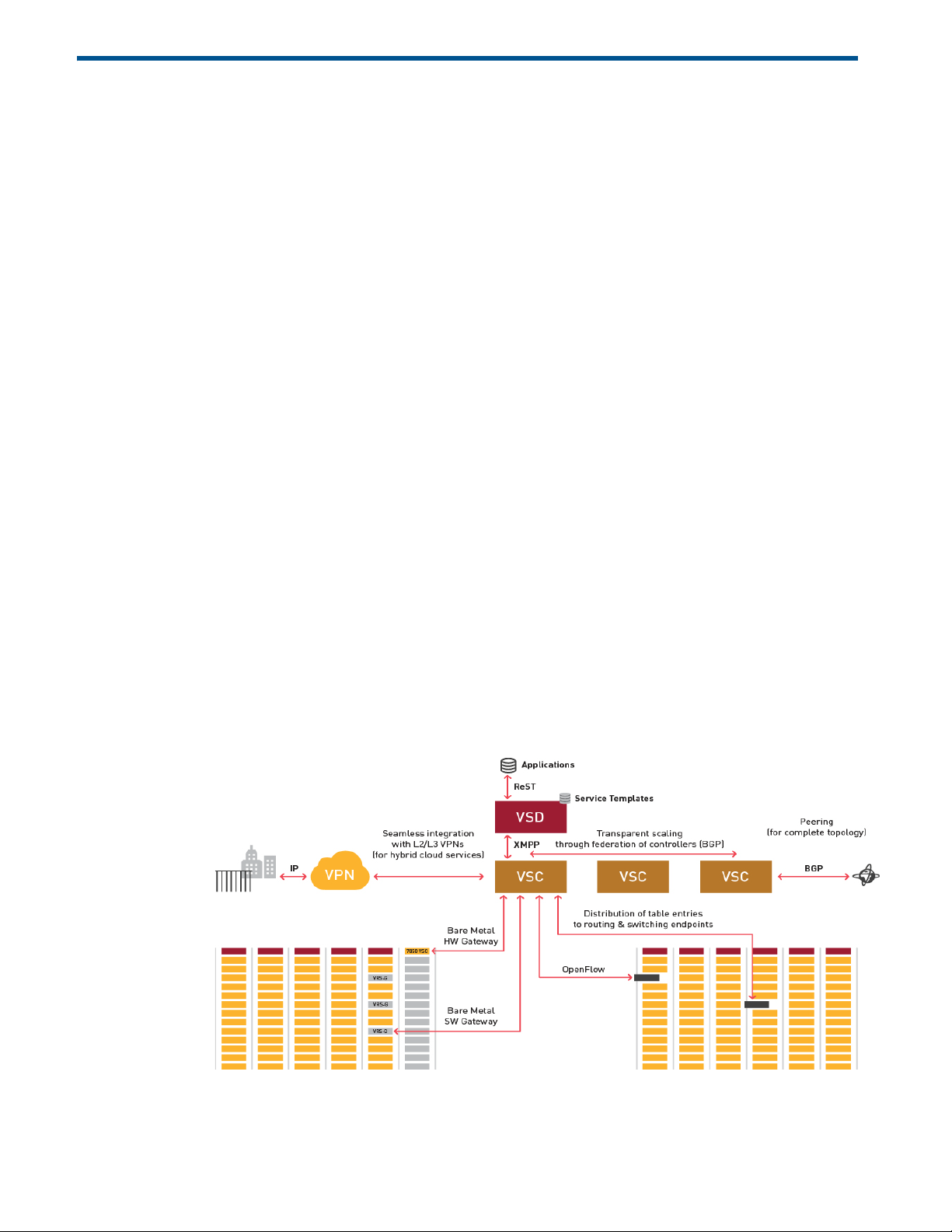
HP DCN Overview
HP DCN is a Software-Defined Networking (SDN) solution that enhances data center (DC)
network virtualization by automatically establishing connectivity between compute resources
upon their creation. Leveraging programmable business logic and a powerful policy engine,
HP DCN provides an open and highly responsive solution that scales to meet the stringent
needs of massive multi-tenant DCs. HP DCN is a software solution that can be deployed over
an existing DC IP network fabric. Figure 1 illustrates the logical architecture of the HP DCN
solution.
Figure1:HPDCNArchitectureandComponents
HP DCN Overview 7
Page 8

There are three main components in the HP DCN solution: HP Virtualized Services Directory
(HP VSD), HP Virtualized Services Controller (HP VSC) and HP Virtual Routing and Switching
(HP VRS).
HP Virtualized Services Directory
HP VSD is a programmable policy and analytics engine that provides a flexible and
hierarchical network policy framework that enables IT administrators to define and enforce
resource policies.
HP VSD contains a multi-tenant service directory which supports role-based administration of
users, computers, and network resources. It also manages network resource assignments such
as IP and MAC addresses.
HP VSD enables the definition of sophisticated statistics rules such as:
• collection frequencies
• rolling averages and samples
• threshold crossing alerts (TCAs).
When a TCA occurs it will trigger an event that can be exported to external systems
through a generic messaging bus.
Statistics are aggregated over hours, days and months and stored in a Hadoop® analytics
cluster to facilitate data mining and performance reporting.
HP VSD is composed of many components and modules, but all required components can run
on a single Linux server or in a single Linux virtual machine. Redundancy requires multiple
servers or VMs.
To get a license key to activate your HP VSD, contact your HP Sales Representative.
HP Virtualized Services Controller
HP VSC functions as the robust network control plane for DCs, maintaining a full view of pertenant network and service topologies. Through the HP VSC, virtual routing and switching
constructs are established to program the network forwarding plane, HP VRS, using the
OpenFlow™ protocol.
The HP VSC communicates with the VSD policy engine using Extensible Messaging and
Presence Protocol (XMPP). An ejabberd XMPP server/cluster is used to distribute messages
between the HP VSD and HP VSC entities.
Multiple HP VSC instances can be federated within and across DCs by leveraging MP-BGP.
The HP VSC is based on HP DCN Operating System (DCNOS) and runs in a virtual machine
environment.
HP Virtual Routing and Switching
HP VRS is an enhanced Open vSwitch (OVS) implementation that constitutes the network
forwarding plane. It encapsulates and de-encapsulates user traffic, enforcing L2-L4 traffic
policies as defined by the HP VSD. The HP VRS tracks VM creation, migration and deletion
events in order to dynamically adjust network connectivity.
8 HP DCN: Overview and Infrastructure
Page 9

HP VRS-G
For low volume deployments the software based HP VRS Gateway (VRS-G) module
incorporates bare metal as virtualized extensions to the datacenter.
HP DCN Infrastructure Requirements and Recommendations
In order to make use of the HP DCN, the data center environment must meet some key
requirements as described in the following sections.
Data Center IP Network
HP VSP can be used in any data center with an IP network. HP VSC actively participates in the
IP routing infrastructure. HP VSCs can run OSPF or IS-IS for the IGP in addition to BGP, but
integration with the IGP is not mandatory.
BGP is used to form a federation of HP VSCs and synchronize the HP VSP network information.
In addition, BGP is also used to exchange routing information with the data center provider
edge router.
NTP Infrastructure
Because HP VSP is a distributed system, it is important that the different elements have a
reliable reference clock to ensure the messages exchanged between the elements have
meaningful timestamps. HP VSP relies on each of the elements having clocks synchronized with
NTP.
The HP VSD and HP VRS applications rely on the NTP facilities provided by the host operating
system. The HP VSC, which is based on HP DCN OS, has an NTP client.
HP recommends having at least three NTP reference clocks configured for each system.
Domain Name System
In scaled HP VSP deployments, the HP VSD functional elements can be distributed across
machines into clusters of machines where the failover and load sharing mechanisms for the
clusters rely on being referenced as a single DNS entity.
Certificate Authority
The northbound ReST API on HP VSD is accessed within an SSL session. The HP VSD is able to
use a self-signed certificate, but having a certificate from a certificate authority will enable
client applications to avoid processing security warnings about unrecognized certificate
authorities.
HP DCN Installation Overview
Installing HP DCN consists of installing the three software components (HP VSD, HP VSC, and
HP VRS) and configuring their interfaces to establish connectivity between them.
HP DCN Infrastructure Requirements and Recommendations 9
Page 10
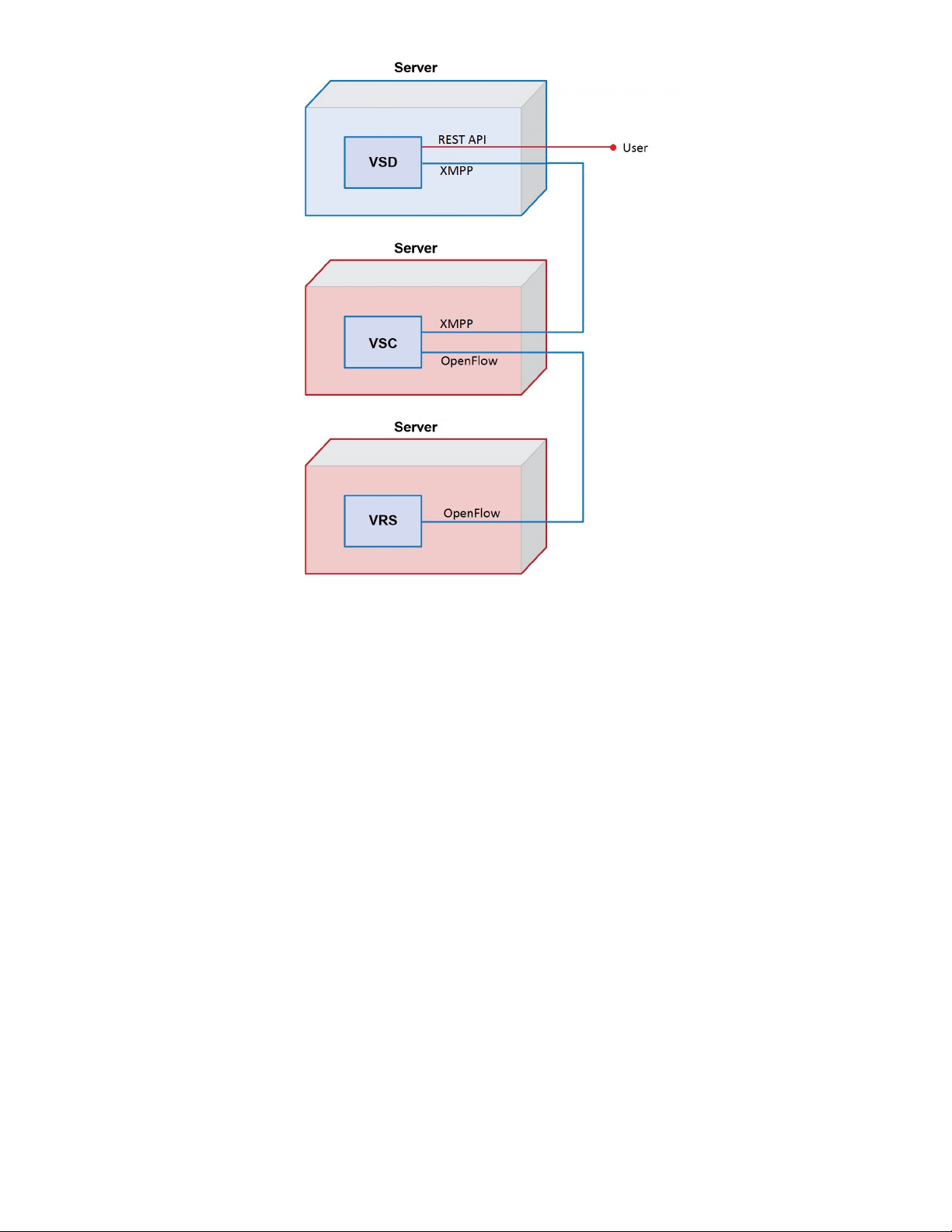
Figure2:InstallationSetup
Figure 2 diagrams the installation of the HP VSP components and shows how they
communicate with each other. The labeled interfaces are referenced in the installation
instructions. The diagram could be used to map out the topology you plan to use for your own
installation.
The recommended order for installing the software is the order presented in this guide because
each newly installed software item component provides the infrastructure to communicate with
the next component on the list.
After installing HP DCN, configure policies in the HP VSD to derive full benefit from the system.
10 HP DCN: Overview and Infrastructure
Page 11

2 HP DCN Software Installation
Topics in this chapter include:
• HP VSD Hardware and Software Requirements
• HP VSD Installation Overview
• HP VSD Installation Using QCow2 Image
• HP VSD Installation Using ISO Disc Image
• Import Certificates on the Servers
• Example of Load Balancer Configuration
HP VSD Hardware and Software Requirements
Installing HP VSD software requires:
• A hypervisor of the specifications set out in the Release Notes
• A mechanism to access the graphical console of the HP VSD appliance (e.g. VNC)
• IP address for the HP VSD appliance(s) and host name(s) defined in DNS and accessible to
all VSP components.
For a license key to activate HP VSD once installed, contact your HP Sales Representative.
HP VSD Installation Overview
The procedures set out here assume installation on a hypervisor running KVM.
Installation Types
There are two types of installation, standalone and high availability.
High Availability
HP VSD High Availability is intended to guard against single-failure scenarios. High
availability for HP VSD is implemented as a 3 + 1 node cluster as shown in Figure 3.
For high availability of the HP VSD nodes, it is necessary to ensure each VSD node has
redundant network and power, so that no single failure can cause loss of connectivity to more
than one HP VSD node. Therefore, each HP VSD node should be installed on a different
hypervisor.
EachHPVSDinstanceandNameNoderequiresanindividualnetworkinterface.Allnodesmust
beIP‐reachable.
HP VSD Hardware and Software Requirements 11
Page 12

Figure3:HPVSD3+1HACluster
The cluster consists of three HP VSD nodes and one statistics master node (Name node). In
addition, a Load Balancer (not supplied) is optional to load balance across the HP VSD nodes
for the REST API.
Installation Methods
The standard method of installation of HP VSD uses the pre-installed appliance. This appliance
is distributed in four formats.
• a ready-to-use QCow2 VM image for KVM hypervisor deployment (see HP VSD Installation
Using QCow2 Image
)
• a ready-to-use image for VMWare hypervisor deployment
• a ready-to-use image for OVA hypervisor deployment
• an ISO disc image (see HP VSD Installation Using ISO Disc Image)
Table 1 provides an overview of the installation tasks with links to each.
Notes on Reinstallation: MySQL Root Password
The password for the MySQL root user is not set after installation, because the HP VSD
installation scripts require that the root user not have a MySQL password.
Reinstalling HP VSD
To reinstall HP VSD, before uninstalling:
1. Set the root password to ‘no password.’ On each node, run:
mysql -uroot -p<current password> -e “update mysql.user set
password=PASSWORD(‘’) where user=’root’; flush privileges;”
2. Uninstall all HP VSD nodes.
3. Install all HP VSD nodes following the procedure specified for your HP VSD version and
installation type.
4. Verify that installation was successful.
5. Set the root password:
To set the root password for the first time, on each node, run:
12 HP DCN Software Installation
Page 13

mysql -e “update mysql.user set password=PASSWORD <NEW PASSWORD>
WHERE USER=’ROOT’; FLUSH PRIVILEGES;”
To change the root password, on each node, run:
mysql -uroot -p<current password> -e “update mysql.user set
password=PASSWORD <new password> where user =’root’; flush privileges;”
Table1:HPVSDInstallationOverview
qcow2 ISO
Set Up Appliance VMs Set Up VM for ISO
Extract and Mount ISO Image
Connect to Appliance VMs
Configure Networking
Configure DNS Server
Configure NTP Server
Install HP VSD using qcow2 Install HP VSD Using ISO
HP VSD Installation Using QCow2 Image
The following instructions are for a High Availability installation. For a standalone installation,
use the same instructions to install one HP VSD on a single node.
1.
Set Up Appliance VMs
2. Connect to Appliance VMs
3. Configure Networking
4. Configure DNS Server
5. Configure NTP Server
Install HP VSD using qcow2
6.
Set Up Appliance VMs
1. Unzip all the HP VSD tar files to a temporary location.
2. If you do not already have virt-install on your hypervisor(s), run this command to put it in:
yum install virt-install
3. Copy the HP VSD qcow2 image to the KVM hypervisor image location <TTY>/var/lib/
libvirt/images/ on each hypervisor.
4. Create appliance VMs.
In the example below, a VM is created for each of four HP VSD nodes. If you are doing a
standalone installation, create only
myh1.
Note: “listen=0.0.0.0” results in KVM responding to VNC connection requests on all IP
interfaces. Depending on your network configuration, this may be a security issue.
HP VSD Installation Using QCow2 Image 13
Page 14

Consider removing “listen=0.0.0.0” and using an alternative method (for
example,
hypervisor1server# vsd_name=myh1
hypervisor1server# vsd_disk=/var/lib/libvirt/images/myh1.qcow2
hypervisor1server# virt-install --connect qemu:///system -n
$vsd_name -r 24576 --os-type=linux --os-variant=rhel6 --disk
path=$vsd_disk,device=disk,bus=virtio,format=qcow2 --vcpus=6 -graphics vnc,listen=0.0.0.0 --noautoconsole --import
hypervisor2server# vsd_name=myh2
hypervisor2server# vsd_disk=/var/lib/libvirt/images/myh2.qcow2
hypervisor2server# virt-install --connect qemu:///system -n
$vsd_name -r 24576 --os-type=linux --os-variant=rhel6 --disk
path=$vsd_disk,device=disk,bus=virtio,format=qcow2 --vcpus=6 -graphics vnc,listen=0.0.0.0 --noautoconsole -import
hypervisor3server# vsd_name=myh3
hypervisor3server# vsd_disk=/var/lib/libvirt/images/myh3.qcow2
hypervisor3server# virt-install --connect qemu:///system -n
$vsd_name -r 24576 --os-type=linux --os-variant=rhel6 --disk
path=$vsd_disk,device=disk,bus=virtio,format=qcow2 --vcpus=6 -graphics vnc,listen=0.0.0.0 --noautoconsole -import
virt-manager or SSH tunnel) to obtain console access.
hypervisor4server# vsd_name=myname
hypervisor4server# vsd_disk=/var/lib/libvirt/images/myname.qcow2
hypervisor4server# virt-install --connect qemu:///system -n
$vsd_name -r 24576 --os-type=linux --os-variant=rhel6 --disk
path=$vsd_disk,device=disk,bus=virtio,format=qcow2 --vcpus=6 -graphics vnc,listen=0.0.0.0 --noautoconsole -import
5. Verify the appliance VMs are running:
hypervisor1server# virsh list --all
Id Name State
--------------------------------- 9 myh1 running
hypervisor2# virsh list --all
Id Name State
--------------------------------- 10 myh2 running
hypervisor3# virsh list --all
Id Name State
--------------------------------- 11 myh3 running
hypervisor4# virsh list --all
Id Name State
--------------------------------- 12 myname running
Connect to Appliance VMs
The HP VSD appliance VM requires console access for initial configuration. Either:
14 HP DCN Software Installation
Page 15

• Connect Via VNC)
• Connect Via virsh Console).
Connect Via VNC
Using a VNC client (e.g. RealVNC, TightVNC) or other console access mechanism, connect to
the HP VSD appliance consoles and log in using the default username and password:
login: root
password: default password
Connect Via virsh Console
Using a virsh console domain command, connect to the HP VSD appliance consoles and
log in using the default username and password.
[root@kvm ~]# virsh list
ID dName State
---------------------------------------------------454 vsd running
[root@kvm ~]# virsh console vsd
Connected to domain vsd
Escape character is ^]
[root@vsd ~]#
Configure Networking
1. Do not use DHCP. Use static IP instead. To do this, modify the file
/etc/sysconfig/network-scripts/ifcfg-eth0 to use your static IP and gateway,
replacing BOOTPROTO value “
BOOTPROTO="static"
IPADDR=192.168.10.101
GATEWAY=192.168.100.1
NETMASK=255.255.255.0
2. Restart networking on the guest:
3. Ping the gateway (in this example, 192.168.100.1).
/etc/init.d/network restart
4. Ping the gateway (in this example, 192.168.100.1).
ping 192.168.100.1
Configure DNS Server
dhcp” with “static”.
Set up the fully qualified names for all the nodes in the cluster (unless you are doing a
standalone installation, in which case one FQDN is obviously sufficient). Reverse DNS lookup
for the HP VSD nodes should also be set up.
Note: If the Service Records (SRV) for the XMPP cluster are not in the Domain Name
Server (DNS), the script will generate them. An administrator must then load them
into the DNS server. The XMPP cluster name is typically xmpp host in the domain,
HP VSD Installation Using QCow2 Image 15
Page 16

for example, xmpp.example.com. To use a different host name run the install.sh
with the -x option.
TheDNSserverinthisexampleis10.10.10.100.
Test DNSandreverseDNSfromeachVSDnode(VM).
1. Set up the fully qualified names for the nodes in the DNS server forward named file as per
the following example:
myh1.myd.example.com. 604800 IN A 192.168.10.101
myh2.myd.example.com. 604800 IN A 192.168.10.102
myh3.myd.example.com. 604800 IN A 192.168.10.103
myname.myd.example.com. 604800 IN A 192.168.10.104
The installation script verifies the DNS forward named file records.
2. From the HP VSD node, verify the SRV record as follows:
server# dig +noall +an @10.10.10.100 SRV _xmpp-client._tcp.xmpp.example.com
_xmpp-client._tcp.xmpp.example.com. 604800 IN SRV 10 0 5222 myh1.myd.example.com.
_xmpp-client._tcp.xmpp.example.com. 604800 IN SRV 10 0 5222 myh2.myd.example.com.
_xmpp-client._tcp.xmpp.example.com. 604800 IN SRV 10 0 5222 myh3.myd.example.com.
_xmpp-client._tcp.xmpp.example.com. 604800 IN SRV 10 0 5222 myname.myd.example.com.
3. Set up the fully qualified names for the nodes in the DNS server reverse named file as per
the following example:
vsd# dig +noall +an @10.10.10.100 -x 192.168.10.101
vsd# dig +noall +an @10.10.10.100 -x 192.168.10.102
vsd# dig +noall +an @10.10.10.100 -x 192.168.10.103
vsd# dig +noall +an @10.10.10.100 -x 192.168.10.104
4. Verify the DNS reverse named file records as follows:
101.10.168.192.in-addr.arpa. 604800 IN PTR myh1.myd.example.com.
102.10.168.192.in-addr.arpa. 604800 IN PTR myh2.myd.example.com.
103.10.168.192.in-addr.arpa. 604800 IN PTR myh3.myd.example.com.
104.10.168.192.in-addr.arpa. 604800 IN PTR myname.myd.example.com.
5. Set up forward DNS records as follows:
; hosts
myh1 A 192.168.10.101
myh2 A 192.168.10.102
myh3 A 192.168.10.103
myname A 192.168.10.104
; xmpp nodes
xmpp A 192.168.10.101
xmpp A 192.168.10.102
xmpp A 192.168.10.103
; SRV records for xmpp.example.com
_xmpp-client._tcp.xmpp.example.com. IN SRV 10 0 5222 myh1.myd.example.com.
_xmpp-client._tcp.xmpp.example.com. IN SRV 10 0 5222 myh2.myd.example.com.
_xmpp-client._tcp.xmpp.example.com. IN SRV 10 0 5222 myh3.myd.example.com.
16 HP DCN Software Installation
Page 17

Configure NTP Server
Include one or more NTP servers in the /etc/ntp.conf file. For example, edit the NTP file and
add servers as follows, restarting the NTPD service to put these parameters into effect:
server 10.10.0.10
server 192.16.10.10
server 192.16.20.10
Install HP VSD using qcow2
The install script is interactive. Node 1 is the master node, and it serves as a template for the
other nodes.
Note: HP VSD consists of several components and providing high availability for each of
these components can be quite complex. It is imperative that the installation and
powering-on of each node be done in the order specified here.
1. Install HP VSD on Node 1.
The install script checks for the XMPP proxy entry in your DNS. Run
install.sh -x xmpp.myd.example.com
[root@myh1 ~]# <TTY>/opt/vsd/install.sh -x xmpp.myd.example.com
----------------------------------------------------| V I R T U A L S E R V I C E S D I R E C T O R Y |
| (c) 2014 HP Networks |
----------------------------------------------------VSD supports two configurations:
1) HA, consisting of 2 redundant installs of VSD with an optional statistics
server.
2) Standalone, where all services are installed on a single machine.
Is this a redundant (r) or standalone (s) installation [r|s]? (default=s):
Is this install the first (1), second (2), third (3) or cluster name node (t)
[1|2|3|t]: 1
Please enter the fully qualified domain name (fqdn) for this node:
, substituting your own XMPP server name.
<TTY>/opt/vsd/
r
myh1.myd.example.com
Install VSD on the 1st HA node myh1.myd.example.com ...
What is the fully qualified domain name for the 2nd node of VSD:
myh2.myd.example.com
What is the fully qualified domain name for the 3rd node of VSD:
myh3.myd.example.com
What is the fully qualified domain name for the cluster name node of VSD:
myname.myd.example.com
What is the fully qualified domain name for the load balancer (if any)
(default=none):
Node 1: myh1.myd.example.com
Node 2: myh2.myd.example.com
Node 3: myh3.myd.example.com
Name Node: myname.myd.example.com
XMPP: xmpp.myd.example.com
Continue [y|n]? (default=y):
Starting VSD installation. This may take as long as 20 minutes in some
situations ...
A self-signed certificate has been generated to get you started using VSD.
You may import one from a certificate authority later.
VSD installed on this host and the services have started.
Please install VSD on myh2.myd.example.com to complete the installation.
y
HP VSD Installation Using QCow2 Image 17
Page 18

2. Install VSD on Node 2:
[root@myh2 ~]# <TTY>/opt/vsd/install.sh
----------------------------------------------------| V I R T U A L S E R V I C E S D I R E C T O R Y |
| (c) 2014 HP Networks |
----------------------------------------------------VSD supports two configurations:
1) HA, consisting of 3 redundant installs of VSD with a cluster name node
server.
2) Standalone, where all services are installed on a single machine.
Is this a redundant (r) or standalone (s) installation [r|s]? (default=s):
Is this install the first (1), second (2), third (3) or cluster name node (t)
[1|2|3|t]:
Please enter the fully qualified domain name for the 1st node of VSD:
myh1.myd.example.com
Install VSD on the 2nd HA node myh2.myd.example.com ...
Node 2: myh2.myd.example.com
Continue [y|n]? (default=y):
Starting VSD installation. This may take as long as 20 minutes in some
situations ...
A self-signed certificate has been generated to get you started using VSD.
You may import one from a certificate authority later.
VSD installed on this host and the services have started.
2
r
3. Follow the interactive script to install HP VSD on Node 3.
4. Follow the interactive script to install HP VSD on the Name Node.
5. Verify that your HP VSD(s) are up and running by using the following command:
service vsd status
6. See Import Certificates on the Servers.
HP VSD Installation Using ISO Disc Image
Note: Consult the Release Notes for the ISO installation requirements.
The following instructions are for a High Availability installation. For a standalone installation,
use the same instructions to install one HP VSD on a single node.
1.
Set Up VM for ISO
2. Extract and Mount ISO Image
3. Configure Networking
4. Configure DNS Server
5. Configure NTP Server
6. Install HP VSD Using ISO
Set Up VM for ISO
Note: “listen=0.0.0.0” results in KVM responding to VNC connection requests on
all IP interfaces. Depending on your network configuration, this may be a security
issue. Consider removing “listen=0.0.0.0” and using an alternative method
(for example,
18 HP DCN Software Installation
virt-manager or SSH tunnel) to obtain console access.
Page 19

1. Bring up a VM named myh1 using 24 GB RAM and 6 logical cores with the following
commands:
# vsd_name=myh1
# vsd_disk=<TTY>/var/lib/libvirt/images/[xxx].qcow2
# virt-install --connect qemu:///system -n $vsd_name -r 24576 --os-type=linux \
--os-variant=rhel6 \
--disk path=$vsd_disk,device=disk,bus=virtio,format=qcow2 \
--vcpus=6 --graphics vnc,listen=0.0.0.0 --noautoconsole --import
2. Repeat this step for each additional hypervisor, naming the additional vsd instances myh2,
myh3, and myname.
Extract and Mount ISO Image
1. Extract the ISO disc image from the tar file to a temporary location.
2. Mount the ISO disc image from the temporary location to <TTY>/media/CDROM/ on each
node.
Note: Ensure that the ISO is mounted to the same location on each node.
Configure Networking, DNS, and NTP
1. See Configure Networking.
2. See Configure DNS Server.
3. See Configure NTP Server.
Install HP VSD Using ISO
1. Install VSD on Node 1.
The install script checks for the XMPP proxy entry in your DNS. Run /media/CDROM/install.sh
-x xmpp.myd.example.com
[root@myh1 ~]# /media/CDROM/install.sh -x xmpp.myd.example.com
----------------------------------------------------| V I R T U A L S E R V I C E S D I R E C T O R Y |
| (c) 2014 HP Networks |
----------------------------------------------------VSD supports two configurations:
1) HA, consisting of 2 redundant installs of VSD with an optional statistics
server.
2) Standalone, where all services are installed on a single machine.
Is this a redundant (r) or standalone (s) installation [r|s]? (default=s):
Is this install the first (1), second (2), third (3) or cluster name node (t)
[1|2|3|t]:
Please enter the fully qualified domain name (fqdn) for this node:
myh1.myd.example.com
Install VSD on the 1st HA node myh1.myd.example.com ...
What is the fully qualified domain name for the 2nd node of VSD:
myh2.myd.example.com
What is the fully qualified domain name for the 3rd node of VSD:
myh3.myd.example.com
What is the fully qualified domain name for the cluster name node of VSD:
myname.myd.example.com
What is the fully qualified domain name for the load balancer (if any)
1
, substituting your own XMPP server name.
r
HP VSD Installation Using QCow2 Image 19
Page 20

(default=none):
Node 1: myh1.myd.example.com
Node 2: myh2.myd.example.com
Node 3: myh3.myd.example.com
Name Node: myname.myd.example.com
XMPP: xmpp.myd.example.com
Continue [y|n]? (default=y):
Starting VSD installation. This may take as long as 20 minutes in some
situations ...
A self-signed certificate has been generated to get you started using VSD.
You may import one from a certificate authority later.
VSD installed on this host and the services have started.
Please install VSD on myh2.myd.example.com to complete the installation.
y
2. Install HP VSD on Node 2:
[root@myh2 ~]# /media/CDROM/install.sh
----------------------------------------------------| V I R T U A L S E R V I C E S D I R E C T O R Y |
| (c) 2014 HP Networks |
----------------------------------------------------VSD supports two configurations:
1) HA, consisting of 3 redundant installs of VSD with a cluster name node
server.
2) Standalone, where all services are installed on a single machine.
Is this a redundant (r) or standalone (s) installation [r|s]? (default=s):
Is this install the first (1), second (2), third (3) or cluster name node (t)
[1|2|3|t]:
Please enter the fully qualified domain name for the 1st node of VSD:
2
r
myh1.myd.example.com
Install VSD on the 2nd HA node myh2.myd.example.com ...
Node 2: myh2.myd.example.com
Continue [y|n]? (default=y):
Starting VSD installation. This may take as long as 20 minutes in some
situations ...
A self-signed certificate has been generated to get you started using VSD.
You may import one from a certificate authority later.
VSD installed on this host and the services have started.
3. Follow the interactive script to install VSD on Node 3.
4. Follow the interactive script to install VSD on the Name Node.
5. Verify that your VSD(s) are up and running by using the following command:
service vsd status
Import Certificates on the Servers
On each HP VSD host, installation generates a self-signed certificate. If you want to import an
official certificate signed by a certificate authority, use the
• Import a certificate generated by a Certificate Authority:
# ./set-cert.sh -r -i certificateFilename
• Generate and use a self-signed certificate if you do not run a proxy:
# ./set-cert.sh -r
20 HP DCN Software Installation
set-cert.sh script:
Page 21

• Generate and use a self-signed certificate if you run a proxy:
# ./set-cert.sh -r -p proxyHostname
Select an option and generate or import the certificate to Node 1. If you are running HA VSD,
import it to Nodes 2 and 3 as well.
LDAP Store
If you are using an LDAP store, see Using an LDAP Store.
Example of Load Balancer Configuration
frontend vsdha *:443
default_backend vsdhaapp
backend vsdhaapp
mode tcp
balance source
server c1 myh1.myd.example.com:8443 check
server c2 myh2.myd.example.com:8443 check
server c3 myh3.myd.example.com:8443 check
frontend main1 *:401
default_backend app1
backend app1
mode tcp
balance source
server c1 myh1.myd.example.com:8443 check
frontend main2 *:402
default_backend app2
backend app2
mode tcp
balance source
server c2 myh2.myd.example.com:8443 check
frontend main2 *:403
default_backend app3
backend app3
mode tcp
balance source
server c3 myh3.myd.example.com:8443 check
Import Certificates on the Servers 21
Page 22

3 HP VSC Software Installation
This chapter provides installation instructions and the basic configuration for the HP VSC.
Topics in this chapter include:
• HP VSC Installation Notes
• HP VSC Software Installation Procedure on KVM
• Emulated Disks Notes
• Emulated Ethernet NIC Notes
• HP VSC Software Installation Procedure on VMware
• Installing HP VSC on ESXI Using OVA
• HP VSC Basic Configuration
• HP VSC Boot Options File Configuration
• HP VSC System and Protocol Configuration
• System-level HP VSC Configuration
• In-band and Loopback IP Interfaces
• Post -install Security Task s
HP VSC Installation Notes
Part of the XML definition of the HP VSC virtual machine is to “pin” the virtual CPUs (vCPUs) to
separate CPU cores on the hypervisor. These settings are required for stable operation of the
HP VSC to ensure internal timers do not experience unacceptable levels of jitter.
Hyperthreading must be disabled to achieve the best use of the physical cores.
For the HP VSC hardware and software requirements, consult the current HP Distributed Cloud
Networking Release Notes.
HP VSC Software Installation Procedure on KVM
This section describes the process of loading the HP VSC software onto the dedicated server. At
the end of the procedure, the HP VSC image will be running on the server, and HP VSC
prompts you to log in.
There are two types of deployment, with a single qcow2 disk or (legacy) with two qcow2 disks
(see
Emulated Disks Notes).
This installation procedure assumes:
• The Linux server is a clean installation with a minimum of configuration and applications.
22 HP VSC Software Installation
Page 23

• An IP address is already assigned for the management network.
• The user has root access to the console of the Linux server.
• Either one or three NTP servers have been configured and NTP has synchronized with
them.
• The user has a means of copying the HP VSC software files to the server.
• Two independent network interfaces for management and data traffic, connected to two
Linux Bridge interfaces.
Once these requirements have been met, install the required dependencies (the following lines
refer to RHEL; substitute the appropriate Ubuntu references):
yum install kvm libvirt bridge-utils
When you set up a server, you must set up an NTP server for all the components. When you
define a VM, it gets a timestamp which cannot deviate more than 10 seconds.
Note: Intel Extended Page Tables (EPT) must be disabled in the KVM kernel module.
If EPT is enabled, it can be disabled by updating modprobe.d and reloading the kernel module
with:
echo "options kvm_intel ept=0" > /etc/modprobe.d/HP_kvm_intel.conf
rmmod kvm_intel
rmmod kvm
modprobe kvm
modprobe kvm_intel
These instructions assume bridges br0 for management and br1 for data have been created
and attached.
1. S t a r t libvirtd and ensure it is set to start automatically.
Prerequisite: Make sure that libvirt and the bridge packages are installed.
For example, with Ubuntu:
service libvirtd start
chkconfig libvirtd on
install kvm libvirt -bin bridge-utils
2. Copy HP VSC disks for libvirt access:
tar xzvf HP-VSC-*.tar.gz
For single disk deployment use:
cd VSC/QCOW_IMAGE/singledisk
For legacy two disk deployment use:
cd VSC/QCOW_IMAGE/twodisks
HP VSC Software Installation Procedure on KVM 23
Page 24

3. Enter:
cp vsc*disk.qcow2 /var/lib/libvirt/images/
chown qemu:qemu /var/lib/libvirt/images/*.qcow2
For Ubuntu:
chown libvirt-qemu:kvm /var/lib/libvirt/images/*.qcow2
4. (Optional) Modify the HP VSC XML configuration to rename the VM or the disk files.
5. Define VM:
virsh define vsc.xml
6. Configure VM to autostart:
virsh autostart vsc
7. Start the VM:
virsh start vsc
8. Connect to the HP VSC console using libvirt:
virsh console vsc
HP VSC should boot to a login prompt on the console.
9. From the console, log in and configure the HP VSC. Default login:
login: admin
password: admin
Emulated Disks Notes
There are two types of HP VSC deployment:
• Single disk configuration requires one QEMU emulated disk in the qcow2 format
(vsc_singledisk.qcow2) configured as IDE 0/1 (bus 0, master). This emulated disk is
accessible within the HP VSC as device “CF1:”
• Two disk configuration requires two QEMU emulated disks in the qcow2 format:
• IDE 0/1 (bus 0, master) must be configured as the “user” disk. The HP VSC
configuration, logs and other user data reside on this disk. This emulated disk is
accessible within the HP VSC as device “CF1:”. A minimum of 1GB is recommended
for this disk (a reference user disk is provided).
• IDE 0/2 (bus 0, slave) must be configured as the “image” disk. This disk contains HP
VSC binaries and a default boot options file. This emulated disk is accessible within the
HP VSC as device “CF2:”. The user should treat this disk as “read only” and essentially
dedicated to use by the image file. After the user customizes the boot options file, the
modified file should be stored on the user disk CF1:.
• It is possible to interchangeably boot different HP VSC versions by using the
corresponding image disk qcow2 file via the libvirt XML.
It is highly recommended to host the “user” disk locally (on CompactFlash, SSD or hard drive
storage as available). Likewise, to achieve the best boot times, it is recommended the “image”
disk be hosted locally on the hypervisor as well.
24 HP VSC Software Installation
Page 25

Emulated Ethernet NIC Notes
Two emulated e1000 Ethernet NICs are required. The HP VSC expects the first NIC to be
connected to the management network and the second NIC to be connected to the data
network.
The recommended configuration is to set up two independent bridges (br## devices in Linux)
and attach the emulated NICs and the corresponding physical NICs to each of these bridges.
See
Appendix: Emulated Ethernet NIC Notes.
HP VSC Software Installation Procedure on VMware
Starting with VSP 3.0, the HP ESXi implementation will provide a new mode of operation that
enables leveraging the underlying ESXi standard Vswitch or distributed Vswitch. As a result,
multiple VMs on the same ESXi host will be able to communicate directly without bridging over
the HP VRS-VM. This brings a tradeoff between performance, use of the underlying Vswitch
(VMware standard vSwitch or dvS) and flow controls inside the same port-group.
The HP implementation is based on VMware's networking paradigm. That is, when multiple
virtual NICs (VNICs) are put together on the same port-group they are able to communicate
with each other (in much the same way that multiple ports on the same VLAN are able to
exchange frames with each other).
When starting a VM, you choose the port-group in which to place the VNICs. Typically, VMs
are placed in the same port-group when they belong to the same subnet. However, there are
other reasons why VNICS might be put together on the same port-group. In any case,
communication is allowed in the same port-group.
The general user workflow for the standard Vswitch mode is the following:
1. Hypervisor installation
a. A Vswitch is defined with at least one port group.
b. The VRS-VM is installed on the hypervisor and the access VNIC is placed on the
standard Vswitch, on a special port-group configured in trunk mode (VLAN 4095). The
VRS-VM is configured at installation time in standard Vswitch mode.
2. Hypervisor usage
a. A new VM A is defined with one VNIC. The VNIC is put into one of the port-groups of
the standard Vswitch (your choice).
b. The VRS-VM receives an event and knows on which VLAN to receive that VM traffic on
its trunk port.
c. The whole instantiation process continues and the VRS-VM hands on the IP on that
specific VLAN.
d. The VNIC is able to communicate through the VRS-VM in a standard HP fashion AND
is also able to communicate with any other VNIC on the same port-group.
HP VSC Software Installation Procedure on VMware 25
Page 26

Installing HP VSC on ESXI Using OVA
Note: It is presumed that vCenter and ESXi are correctly installed.
1. Enable SSH on the ESX hypervisor. You can do this over the ESX screen or from vCenter.
2. Disable firewall on the ESXi. Run the following CLI on the ESXi host that will run the HP
VSC:
esxcli network firewall set --enabled false
3. Select the host:
4. Select Edit > Deploy OVF template:
5. In the Deploy OVF Template window that appears, click Browse and select the source
location of the OVF file, and
thenclickNext.
26 HP VSC Software Installation
Page 27

6. Specify a name and location for the deployed template, and then clickNext.:
7. Select a resource pool within which to deploy the template, and
HP VSC Software Installation Procedure on VMware 27
thenclickNext.
Page 28

8. Select the format in which to store the virtual disks, and thenclickNext.
9. Map the networks used in this OVF template to networks in your inventory (select the port
groups), and
thenclickNext.
10. Enter the HP VSC configuration information.
28 HP VSC Software Installation
Page 29

Note: Note that you must enter the control IP addresses of the HP VSC peers in the BGP
peer fields.
HP VSC Software Installation Procedure on VMware 29
Page 30

Then click Next. A summary is displayed.
11. To close the summary, click Finish.
12. Before powering on the VM, add a serial port. Connect via Network, Network Backing to
Server, Port URI to telnet://:2500 (this can be any port number).
13. Connect to the serial console of the TIMOS VM using a terminal application, such as PuTTY.
14. (Optional) Select one of the three boot options:
• HP VSC
• Update HP VSC configuration and reboot
• Update HP VSC configuration
If you do not make a choice within 20 seconds, the first option—HP VSC— is automatically
selected and the VM boots from the vApp properties that you gave initially.
To boot up the VSC VM implementing the new information, use the second option—Update
HP VSC configuration and reboot.
To make changes inside the VM before booting SROS, use the third option—Update HP
VSC configuration. Instructions for making such changes are beyond the scope of this
document. Do not make such changes unless you know what you are doing.
30 HP VSC Software Installation
Page 31

HP VSC Basic Configuration
This section describes the intial configuration steps necessary to get the HP VSC up and
running and able to communicate with other elements in the VSP.
The procedures described include:
• HP VSC Boot Options File Configuration
• HP VSC System and Protocol Configuration
HP VSC Boot Options File Configuration
The HP VSC uses a Boot Options File (BOF) named bof.cfg that is read on system boot and is
used for some basic, low-level system configuration needed to successfully boot the HP VSC.
Table 5 lists the configuration paramaters that are set in the BOF that are needed for proper
operation of the HP VSC.
Table5:BOFParameters,DefaultsandDescriptions
Parameter DefaultValue DescriptionandNotes
primary-image cf2:/timos/cpm.tim
primary-config cf1:/config.cfg
address
primary-dns
secondary-dns
tertiary-dns
dns-domain
static-route
wait
nodefault TheIPaddressoftheManagementIPinterface
nodefault TheIPaddressesoftheprimary,secondaryand
nodefault TheDNSdomainoftheHPVSC.
nodefault Configuresastaticrouteforsubnetsreachable
3seconds Configuresapauseinsecondsatthestartof
Theimagefilefromwhichthesystemwi ll
attempttoboot.
Theprimary(first)configurationfilethesystem
willattempttoloadonboot.Thereareaddi‐
tionalparametersforsecondaryandtertiary
configurationfilesshouldthesystembeunable
tolocatethespecifiedconfiguration.
(alsocalledthe“out‐of‐band”interfaceinthe
HPVSCasthisisnormallyonthedatacenter’s
managementnetwork).
tertiaryDNSserversthattheHPVSCwillrefer‐
enceforDNSnameresolution.
throughtheManagementIPinterface.
thebootprocesswhichallowssysteminitializa‐
tiontobeinterruptedattheconsole.
Whensysteminitializationisinterrupted,the
operatorisallowedtomanuallyoverridethe
parametersdefinedintheBOF.
HP VSC Basic Configuration 31
Page 32

Table5:BOFParameters,DefaultsandDescriptions(Continued)
Parameter DefaultValue DescriptionandNotes
persist off
Specifieswhetherthesystemwillcreateaper‐
sistencyfile(.ndx)whichwillpreservesystem
indexes(forexample,theIPinterfaceMIB
objectindex)acrossasystemreboot.This
parameteristypicallyturnedonwhentheHP
VSCismanagedwithSNMP.
ip-address-dhcp
nodefault Thisoptionalparametershouldbeconfigured
intheHPVSCbof.cfgtotriggerDHCPresolution
atbootup.Whenthiscommandispresent,if
anaddressispresentitwillbeignoredon
reboot,andtheHPVSCwillobtainitsmanage‐
mentIPviaaDHCPexchange(assumingthere
operlyconfiguredDHCPserveronthe
isapr
network).
The following procedure updates the BOF and save the updated bof.cfg file on the “user” disk
CF1:.
Note: The “image” disk CF2: has a default bof.cfg file, but any user modified bof.cfg
should be stored on the “user” disk CF1.
This installation procedure assumes:
1. The HP VSC software has been successfully installed.
2. The user is at the HP VSC console and waiting to log in for the first time.
The information that is configured in the BOF is the following:
• The IP address of the Management IP interface (192.168.1.254 in the example below).
• As appropriate, the IP addresses of the primary, secondary and tertiary DNS servers
(10.0.0.1, 10.0.0.2 and 10.0.0.3 respectively in the example below).
• The DNS domain of the HP VSC (example.com in the example below).
• The IP next hop of any static routes that are to be reached via the Management IP interface
(one static route to subnet 192.168.100.0/24 via next hop 192.168.1.1 in the example
below).
• [Optional] Index persistence file for SNMP managed HP VSCs
1. Log in to the HP VSC console as administrator
At the “login as:” prompt, use the default administrator username (“admin”) and password
(“admin”) to log into the system and be at the root CLI context:
*A:NSC-vPE-1#
2. Assign the Management IP address
To navigate to the Boot Options File context, enter “bof<Enter>” and the prompt will
indicate a change to the bof context:
32 HP VSC Software Installation
Page 33

*A:VSC-1>bof#
The management IP address is configured using the address command which has a syntax
of:
[no]addressip‐prefix/ip‐prefix‐length[active|standby]
where keywords are in bold, parameters are in italics and optional elements are enclosed
in square brackets. “[ ]”. Typically, the no form of the command will remove the configured
parameter or return it to its default value.
In the input below, the management IP is set to 192.168.1.254/24:
*A:VSC-1>bof# address 192.168.1.254/24
3. Configure DNS servers
The HP VSC allows for up to three DNS servers to be defined that will be contacted in
order: primary, secondary and tertiary. If one DNS is not reachable, the next DNS is
contacted.
The DNS servers are configured with the following command syntax:
primary‐dnsip‐address
noprimary‐dns
secondary‐dnsip‐address
nosecondary‐dns
tertiary‐dnsip‐address
notertiary‐dns
The primary, secondary and tertiary DNS servers are configured to 10.0.0.1, 10.0.0.2 and
10.0.0.3, respectively, with the following commands:
*A:VSC-1>bof# primary-dns 10.0.0.1
*A:VSC-1>bof# secondary-dns 10.0.0.2
*A:VSC-1>bof# tertiary-dns 10.0.0.3
4. Configure the DNS domain
The HP VSC DNS domain is set with the dns-domain command which has the following
syntax:
dns‐domaindns‐name
nodns‐domain
The DNS domain is set to example.com with the command below:
*A:VSC-1>bof# dns-domain example.com
5. Configure static routes for the management IP network
A static route is configured for the management IP interface with the static-route command
which has the following syntax:
HP VSC Basic Configuration 33
Page 34

[no]static‐routeip‐prefix/ip‐prefix‐lengthnext‐hopip‐address
Multiple static-route commands can be issued for the Management IP interface.
A static route is added for 192.168.100.0/24 with a next hop of 192.168.1.1 with the
command below:
*A:VSC-1>bof# static-route 192.168.100.0/24 next-hop 192.168.1.1
To check connectivity:
ping router “management” <Gateway IP>
6. [Optional] Enable index persistence for SNMP managed HP VSCs
If the HP VSC is going to be managed using SNMP, it is recommended that index
persistence be enabled using the persist command to ensure that MIB objects, like IP
interfaces, retain their index values across a reboot. The .ndx file that saves all of the
indexes in use is saved on the same device as the configuration file whenever a save
command is issued to save the HP VSC configuration.
The persist command has the following syntax:
persist{on|off}
To enable index persistence, the command is:
*A:VSC-1>bof# persist on
7. Save the configuration to cf1:
The BOF file is normally saved in the same directory as the image file for DCNOS , but for
the HP VSC, it is recommended that the bof.cfg file be saved to the cf1: “user” emulated
disk.
Note: The “image” disk CF2: has a default bof.cfg file, but any user modified bof.cfg
should be stored on the “user” disk CF1:.
The command to save the BOF to cf1: is:
*A:VSC-1>bof# save cf1:
8. Reboot the HP VSC to load the saved boot options
After saving the BOF, the system needs to rebooted because the bof.cfg is only read on
system initialization.
To reboot the HP VSC, issue the following commands:
*A:VSC-1>bof# exit
*A:NSC-vPE-1# admin reboot
WARNING: Configuration and/or Boot options may have changed since the last
save.
Are you sure you want to reboot (y/n)? y
The exit command returns the CLI to the root context so that the admin reboot command
can be issued to reboot the system. Answer in the affirmative to reboot.
34 HP VSC Software Installation
Page 35

After rebooting, the IP management interface for the HP VSC is configured along with
DNS.
HP VSC System and Protocol Configuration
In addition to the (“out-of-band”) Management IP interface, the HP VSC has an (“in-band”)
network interface for the data center’s data network.
In order to utilize the in-band network interface and provide connectivity with the other VSP
elements, the HP VSC requires some additional system-level configuration as well as in-band
data network configuration.
The system-level configuration required includes:
• Assigning a system name.
• Defining NTP servers to be used by the system.
• Configuring the system time zone.
• Configuring the XMPP client and OpenFlow in the HP VSC.
Configuring the IP interfaces and network protocols:
• Creating the in-band IP interface and assigning an IP address (interface name control and
IP address 10.9.0.7/24 in the example configuration below).
• Creating a system loopback IP interface for use by network protocols (interface name
system and IP address 10.0.0.7/32 in the example configuration below).
• Configure network protocols, for example, OSPF, IS-IS and BGP.
The sections below describe the configuration required by highlighting the relevant commands
of a HP VSC configuration file. The HP VSC configuration file contains the CLI commands
where the commands are formatted for enhanced readability.
After configuration, use the following command to save the configuration:
vsc# admin save
System-level HP VSC Configuration
Information on the XMPP server and OpenFlow commands on the VRS can be found in the
current HP Distributed Cloud Networking User Guide.
System Name
The config>system>name command is used to configure the system name. In the excerpt below,
the system name is set to NSC-vPE-1.
#--------------------------------------------------
echo "System Configuration"
#--------------------------------------------------
exit all
configure
system
name "NSC-vPE-1"
HP VSC Basic Configuration 35
Page 36

snmp
shutdown
exit
exit all
NTP Servers and Time Zone
Having the different VSP elements time synchronized with NTP is essential to ensure that the
messages passed between the VSD, HP VSC and VRS elements are appropriately timestamped
to ensure proper processing.
Specify one or more (and preferrably three) NTP servers should be defined like in the example
below (10.0.0.123, 10.10.10.18 and 10.200.223.10).
The time zone is set with the zone command (PST) with the daylight savings time zone set with
the dst-zone command (PDT). The dst-zone will automatically complete the start and end dates
and times, but can be edited if needed.
exit all
configure
system
time
ntp
server 10.0.0.123
server 10.10.10.18
server 10.200.223.10
no shutdown
exit
sntp
shutdown
exit
dst-zone PDT
start second sunday march 02:00
end first sunday november 02:00
exit
zone PST
exit
exit all
XMPP and OpenFlow
Specify the xmpp server (xmpp.example.com) and username (NSC-vPE-1) and password
(password). The ejabberd server is configured to auto-create the user on the server with the
supplied username and password.
For OpenFlow, optional subnets can be specified with the auto-peer command which restricts
inbound OpenFlow connections from that subnet. If no auto-peer stanza is configured,
OpenFlow will sessions will be accepted on all interfaces, both in-band and out-of-band.
36 HP VSC Software Installation
Page 37

#--------------------------------------------------
echo "Virtual Switch Controller Configuration"
#--------------------------------------------------
exit all
configure
vswitch-controller
xmpp-server "NSC-vPE1:password@xmpp.example.com"
open-flow
auto-peer 10.9.0.0/24
exit
exit
xmpp
exit
exit
In-band and Loopback IP Interfaces
The excerpt below shows how to configure the in-band interface IP (name control with IP
address 10.9.0.7) as well as the loopback (name system with IP address 10.0.0.7) IP
interfaces. The loopback IP is needed if any IGP or BGP routing protocols will be configured. If
using BGP, an autonomous system needs to be configured (65000). Optionally, static routes
can be configured as well (for the in-band) routing table.
#--------------------------------------------------
echo "Router (Network Side) Configuration"
#--------------------------------------------------
exit all
configure
router
interface "control"
address 10.9.0.7/24
no shutdown
exit
interface "system"
address 10.0.0.7/32
no shutdown
exit
autonomous-system 65000
#--------------------------------------------------
echo "Static Route Configuration"
#--------------------------------------------------
static-route 1.2.3.4/32 next-hop 10.9.0.100
exit all
Network Protocols (OSPF and BGP)
The following sections show the commands to configure OSPF for area 0.0.0.0.
HP VSC Basic Configuration 37
Page 38

#--------------------------------------------------
echo "OSPFv2 Configuration"
#--------------------------------------------------
exit all
configure
router
ospf
area 0.0.0.0
interface "system"
no shutdown
exit
interface "control"
no shutdown
exit
exit
exit
exit
exit all
BGP needs to be configured if there are multiple HP VSCs that will be operating as a
federation. The following is just a sample configuration and should be adapted according to
the existing BGP infrastructure (for example, the use of Route Reflectors, the bgp group
neighbor IP addresses and family types should be specified, etc.).
38 HP VSC Software Installation
Page 39

#--------------------------------------------------
echo "BGP Configuration"
#--------------------------------------------------
exit all
configure
router
bgp
connect-retry 2
min-route-advertisement 1
outbound-route-filtering
extended-community
send-orf
exit
exit
group "internal"
type internal
neighbor <ip-address>
family vpn-ipv4
exit
neighbor <ip-address>
family evpn
exit
exit
no shutdown
exit
exit
exit all
Post-install Security Tasks
After installing the HP VSC software, there are a number of tasks that should be performed to
secure the system. Most of these tasks are obvious, but worth mentioning as a reminder.
• Change HP VSC “admin” password
By default, the HP VSC administrator username and password are “admin”. Finding the
default credentials for most systems and software is not difficult and is an easy security
exploit.
• Centralized HP VSC authentication and authorization
The HP VSC software is based on DCNOS and inherits many of the platform and security
features supported in DCNOS. Rather than rely on users defined locally on each VRS,
RADIUS and TACACS+ can be used to centralize the authentication and authorization for
VRS administrative users.
Post-install Security Tasks 39
Page 40

• Secure Unused TCP/UDP Ports
After installing and configuring the HP VSC, the user should take all steps necessary to
ensure the network security of the HP VSC system through the use of ACLs and/or firewalls
and by disabling any unneeded network services on the node.
Table 6 lists the required and optional UDP/TCP ports for particular services for inbound
connections to the HP VSC.
Table 7 lists required and optional UDP/TCP ports for particular services for outbound
connections from the HP VSC.
Optional ports are only required if the network service is in use on the HP VSC.
Table6:HPVSCUDP/TCPInbound/OpenedPorts
Port UDP/TCP Required/
Optional
ProtocolNotes
21/22 TCP Optional FTP
22 TCP Optional SSH
23 TCP Optional Telnet
123 UDP Required NTP
161/162 UDP Optional SNMP‐requiredforSNMPmanagement
179 TCP Required BGP‐requiredforfederatedHPVSCs
6633 TCP Required OpenFlow
49152‐
65535
UDP Optional RADIUSforconsoleuserauthentication
dynamicallyreservesportsinthisrange
uponinitializationoftheHPVSCforout‐
goingconnectionsandtheresulting
response.Theportsusedinthisrange
canbeviewedwith“showsystemcon‐
nections”.
IfRADIUSnotused,noincomingpackets
willbeforwardedorprocessed.
Port UDP/TCP Required/
21/22 TCP Optional FTP
22 TCP Optional SSH
23 TCP Optional Telnet
49 TCP Optional TACACS+
53 UDP/TCP Required DNS
40 HP VSC Software Installation
Table7:HPVSCUDP/TCPOutbound/RemotePorts
ProtocolNotes
Optional
Page 41

Table7:HPVSCUDP/TCPOutbound/RemotePorts(Continued)
Port UDP/TCP Required/
Optional
ProtocolNotes
69 UDP Optional TFTP
123 UDP Required NTP
161/162 UDP Optional SNMP‐requiredforSNMPmanagement
179 TCP Required BGP‐requiredforfederatedHPVSCs
514 UDP Optional Syslog
6633 TCP Required OpenFlow
Post-install Security Tasks 41
Page 42

4 HP VRS and VRS-G Software Installation
This chapter provides installation instructions and the basic configuration for HP Virtual Routing
and Switching (VRS) and HP Virtual Routing and Switching Gateway (VRS-G).
Topics in this chapter include:
• VRS and VRS-G Installation Overview
• Preparing the Hypervisor
• Installing the VRS or VRS-G Software
• Configuring and Running VRS or VRS-G
VRS and VRS-G Installation Overview
VRS—The VRS component is a module that serves as a virtual endpoint for network services.
Through VRS, changes in the compute environment are immediately detected, triggering
instantaneous policy-based responses in network connectivity to ensure that application needs
are met.
VRS is an enhanced Open vSwitch (OVS) implementation that constitutes the network
forwarding plane. It encapsulates and de-encapsulates user traffic, enforcing L2-L4 traffic
policies as defined by the VSD. The VRS includes a Virtual Agent (VA) that tracks VM creation,
migration and deletion events in order to dynamically adjust network connectivity.
VRS‐G—The VRS-G component is a software gateway between the HP DCN networks and
legacy VLAN-based networks. It can be installed either on a bare metal server or within a VM.
For optimum performance, bare metal is recommended.
OperatingSystemandHardwareRequirements—See the Release Notes.
InstallationProcedure—Installation is essentially a three (or four) phase operation:
1.
Preparing the Hypervisor.
2.
Installing the VRS or VRS-G Software: The procedures are slightly different for the two
components and for each supported operating system, therefore each procedure is given
separately.
3. If you need MPLS over GRE:
4. Configuring and Running VRS or VRS-G.
Installing the VRS Kernel Module for MPLS over GRE.
Preparing the Hypervisor
Before installation of VRS/VRS-G, the following requirements must be met for all operating
systems:
42 HP VRS and VRS-G Software Installation
Page 43

• The Linux server must be a clean installation with a minimum of configuration and
applications.
• An IP address must already have been assigned to the server.
• DNS must have already been configured and must be operational.
• At least two NTP servers must have been configured and NTP must have been synchronized
with them.
• There must be root access to the console of the Linux server.
• You must have the ability to download and install software from remote archives, or have a
local repository mirror for the required repositories.
• The VRS software files must have been copied to the server.
Installing the VRS or VRS-G Software
This section contains:
• VRS on RHEL
• VRS on Ubuntu 12.04 LTS with Ubuntu 12.04 Cloud Packages
VRS on RHEL
• VRS-G on RHEL or Ubuntu 12.04
• Installing the VRS Kernel Module for MPLS over GRE
• Installing the VRS Kernel Module for MPLS over GRE
• Installing VRS Kernel Module On RHEL
• Installing VRS Kernel Module On Ubuntu 12.04
Note: For the currently supported software versions and hardware, consult the release
notes for the current version of HP DCN.
The HP VRS .tar.gz file contains the additional HP-specific packages. Install them following the
process below.
Note: VRSmustbeinstalledfromlocallydownloadedRPMfilesunlessithasbeenadded
toacustomrepository(whichisbeyondthescopeofthisdocument).
Note: SinceCentOS6isacommunityeditionofEnterpriseLinuxwhichisbinary
compatiblewithRHEL,VRSshouldalsoworkonCentOS6.
1. Update your system:
yum update
2. Install dependencies for RHEL:
yum install libvirt
yum install python-twisted
Installing the VRS or VRS-G Software 43
Page 44

yum install perl-JSON
yum install qemu-kvm
yum install vconfig
3. Install the VRS package for RHEL:
tar xzvf <filename>
4. Do a yum localinstall of the HP-openvswitch package.
5. Edit
/etc/default/openvswitch to achieve the desired VRS configuration. The comments
in the file are self-explanatory. Add the VSC controller’s IP addresses:
vi /etc/default/openvswitch
6. If you have modified /etc/default/openvswitch, restart:
# service openvswitch restart
[root@ovs-1 ~]# service openvswitch restart
Stopping HP system monitor:Killing HP-SysMon (15377) [ OK ]
Stopping HP rpc server:Killing HP-rpc (15400) [ OK ]
Stopping HP monitor:Killing HPMon (15409) [ OK ]
Stopping vm-monitor:Killing vm-monitor (15419) [ OK ]
Stopping openvswitch: ovs-brcompatd is not running.
Killing ovs-vswitchd (15352) [ OK ]
Killing ovsdb-server (15337) [ OK ]
Removing openvswitch module [ OK ]
Starting openvswitch:Inserting openvswitch module [ OK ]
Starting ovsdb-server [ OK ]
Configuring Open vSwitch system IDs [ OK ]
Configuring Open vSwitch personality [ OK ]
Starting ovs-vswitchd [ OK ]
Starting HP system monitor:Starting HP-SysMon [ OK ]
Starting HP rpc server:Starting HP-rpc [ OK ]
Starting HP monitor:Starting HPMon [ OK ]
Starting vm-monitor:Starting vm-monitor [ OK ]
7. If you did not modify /etc/default/openvswitch, restart and verify that the VRS
processes restarted correctly:
# service openvswitch restart
Stopping HP monitor:Killing HPMon (6912) [ OK ]
Stopping vm-monitor:Killing vm-monitor (6926) [ OK ]
Stopping openvswitch: Killing ovs-brcompatd (6903) [ OK ]
Killing ovs-vswitchd (6890) [ OK ]
Killing ovsdb-server (6877) [ OK ]
Removing brcompat module [ OK ]
Removing openvswitch module [ OK ]
44 HP VRS and VRS-G Software Installation
Page 45

Starting openvswitch:Inserting openvswitch module [ OK ]
Inserting brcompat module [ OK ]
Starting ovsdb-server [ OK ]
Configuring Open vSwitch system IDs [ OK ]
Configuring Open vSwitch personality [ OK ]
Starting ovs-vswitchd [ OK ]
Starting ovs-brcompatd [ OK ]
Starting HP monitor:Starting HPMon [ OK ]
Starting vm-monitor:Starting vm-monitor [ OK ]
VRS on Ubuntu 12.04 LTS with Ubuntu 12.04 Cloud Packages
The HP-VRS Ubuntu 12.04 .tar.gz file contains the additional HP-specific packages. Install them
following the process below.
Note: VRSissupportedontheUbuntu12.04PreciseLongTermSupportoperating
system,withadditionalpackagescomingfromtheUbuntu12.04Cloudrepository.
Note: The supported kernel version corresponds to the Trusty hardware enablement stack.
Any new install of Ubuntu 12.04 will contain this kernel. (For more information, see
https://wiki.ubuntu.com/Kernel/LTSEnablementStack.)
Note: VRS must be installed from locally downloaded .deb files unless it has been added
to a custom repository (which is beyond the scope of this document).
1. Enable the Ubuntu 12.04 cloud repository:
sudo add-apt-repository cloud-archive:grizzly
Note: Moredetailsonthecloudrepositoriescanbefoundonhttps://wiki.ubuntu.com/
ServerTeam/CloudArchive.
2. Update your system:
sudo apt-get update
sudo apt-get upgrade
3. Verify your kernel version:
uname -r
4. If you do not have the correct kernel, activate the Trusty hardware enablement kernel:
sudo apt-get install --install-recommends linux-generic-lts-trusty
5. Reboot:
reboot
6. Install dependencies:
apt-get install qemu-kvm libvirt-bin libjson-perl python-twisted-core vlan
7. Install the following packages using dpkg -i
Installing the VRS or VRS-G Software 45
Page 46

• hp-openvswitch-common
• hp-openvswitch-switch
• hp-python-openvswitch
Note: Donotinstalleitherhp‐openvswitch‐datapath‐dkms(seeInstalling the VRS Kernel
Module for MPLS over GRE
)orhp‐metadata‐agent(whichisreservedfor
OpenStackdeployments).ForOpenStackconfiguration,refertotheOpenStack
deploymentguide.
Note: dpkg‐iwillnotsolvedependencies.Ifyouaremissingdependencies,installthem:
apt-get -f install Thenrunthesamedpkgcommandagain.
8. Edit /etc/default/openvswitch to achieve the desired VRS configuration. The comments
in the file are self-explanatory. Add the VSC controller's IP addresses:
vi /etc/default/openvswitch
9. Restart the service to pick up the changes in /etc/default/openvswitch:
# service hp-openvswitch-switch restart
Stopping hp system monitor: * Killing hp-SysMon (21054)
Stopping hp rpc server: * Killing hp-rpc (21083)
Stopping hp monitor: * Killing hpMon (21086)
Stopping openvswitch: * ovs-brcompatd is not running
* Killing ovs-vswitchd (21038)
* Killing ovsdb-server (21019)
* Removing openvswitch module
* Inserting openvswitch module
* Starting ovsdb-server
* Configuring Open vSwitch system IDs
* Configuring Open vSwitch personality
* Starting ovs-vswitchd
Starting hp system monitor: * Starting hp-SysMon
Starting hp rpc server: * Starting hp-rpc
Starting hp monitor: * Starting hpMon
VRS-G on RHEL or Ubuntu 12.04
1. Install VRS following the instructions in either of the following:
• VRS on RHEL.
• VRS on Ubuntu 12.04 LTS with Ubuntu 12.04 Cloud Packages
2. Edit /etc/default/openvswitch-switch by setting PERSONALITY=vrs-g.
3. Restart the VRS service:
service openvswitch restart
Installing the VRS Kernel Module for MPLS over GRE
This section contains the following subsections:
• Installing VRS Kernel Module On RHEL
46 HP VRS and VRS-G Software Installation
Page 47

• Installing VRS Kernel Module On Ubuntu 12.04
Installing VRS Kernel Module On RHEL
1. Install VRS following the instructions in VRS on RHEL.
2. Enable the EPEL repository:
rpm -Uvh https://dl.fedoraproject.org/pub/epel/6/x86_64/epel-release-6-
8.noarch.rpm
Note: IftheEPELrepositoryinstallfails,checkhttps://fedoraproject.org/wiki/EPELforthe
latestepel‐releasepackageversionandlocation.
3. Install dependencies for DKMS:
yum install dkms
yum install kernel-devel
4. Reboot to pick up correct kernel:
reboot
Note: VRSinstallwillfailiftheinstalledversionofkernel‐develisnotthesameasthe
currentlyrunningkernel.
5. Verify that the installed version of kernel-devel is the same as the currently running
kernel:
• To verify which version of kernel-devel is installed:
rpm -qa | grep kernel-devel
• To verify which kernel is currently running:
uname -r
Note: Ifyouareunabletousethelatestkernel,installkernel‐develpackagesforyour
currentlyrunningkernel:
yum install kernel-devel-`uname -r`
6. Do a yum localinstall of the hp-openvswitch-dkms package.
7. Verify that the VRS processes restarted correctly:
# service openvswitch restart
Stopping hp monitor:Killing hpMon (6912) [ OK ]
Stopping vm-monitor:Killing vm-monitor (6926) [ OK ]
Stopping openvswitch: Killing ovs-brcompatd (6903) [ OK ]
Killing ovs-vswitchd (6890) [ OK ]
Killing ovsdb-server (6877) [ OK ]
Removing brcompat module [ OK ]
Removing openvswitch module [ OK ]
Starting openvswitch:Inserting openvswitch module [ OK ]
Inserting brcompat module [ OK ]
Starting ovsdb-server [ OK ]
Configuring Open vSwitch system IDs [ OK ]
Installing the VRS or VRS-G Software 47
Page 48

Configuring Open vSwitch personality [ OK ]
Starting ovs-vswitchd [ OK ]
Starting ovs-brcompatd [ OK ]
Starting hp monitor:Starting hpMon [ OK ]
Starting vm-monitor:Starting vm-monitor [ OK ]
Installing VRS Kernel Module On Ubuntu 12.04
1. Install VRS following the instructions in VRS on Ubuntu 12.04 LTS with Ubuntu 12.04 Cloud
Packages
2. Install dependencies for DKMS:
apt-get install dkms linux-headers-`uname -r`
3. Reboot to pick up correct kernel:
reboot
4. Install the hp-openvswitch-datapath-dkms package using the dpkg -i command.
5. Verify that the VRS processes restart correctly:
# service openvswitch restart
.
Configuring and Running VRS or VRS-G
The HP startup script that is provided takes care of starting all the components as well as the
basic configuration of VRS. This is mainly the creation of a bridge into VRS and the assignment
of an OpenFlow controller to that bridge. The configuration is loaded upon startup of the
openvswitch script according to a configuration file.
1. Edit the configuration file at
the active and standby VSC:
ACTIVE_CONTROLLER=1.2.3.4
STANDBY_CONTROLLER=1.2.4.5
2. Restart the VRS or VRS-G.
3. Verify VRS connected to VSC successfully:
ovs-vsctl show
To customize, use scripts that you run after bootup.
Note: Customizationscriptsmustbererunaftereveryreboot.BecauseofthenewISO
image,changesarenotpersistentacrossreboots.
/etc/default/openvswitch by specifying the IP addresses of
48 HP VRS and VRS-G Software Installation
Page 49

5 VMware VRS VM Deployment
Topics in this chapter include:
• Introduction
• Prerequisites
• Creating the dVSwitch
• Verifying the Creation of the dVSwitch
• vSphere vSwitch Configurations
• Deployment of dVRS
• Information Needed
• Verifying Deployment
Introduction
Prerequisites
This chapter describes the integration of the Virtual Routing and Switching (VRS) VM with
VMware that is required for all VMware deployments with VMware vSphere Hypervisor (ESXi).
The integration requires creating the dVSwitch, configuring vSphere vSwitch, and deploying the
dVSwitch.
Note: Workflow and VSD must be NTP synced. Lack of synchronization could lead to
failure of operations on VSD.
Procure the following packages:
• CloudMgmt-vmware
• VRS OVF Templates for VMware
For Multicast to work on ESXi:
• Before installation, a new port-group (for example, Multicast-source) should be created on
the vSwitch which connects to the external network (SR-1) and promiscuous mode should be
allowed by default.
Creating the dVSwitch
BeforecreatingthedVSwitch,makesureyouhavethefollowinginformation:
• VCENTER_IP
• VCENTER_USER
Introduction 49
Page 50

• VCENTER_PASSWD
• CLUSTER_NAME
From the CloudMgmt-vmware package, run the command
arguments, taking account of the note below.
bash# ./cli.bash create_dvswitch --add-hosts true
--num-portgroups 1
--provider-vdc-id 1
--url https://<VCENTER_IP>/sdk
-u <VCENTER_USER>
-p <VCENTER_PASSWD>
-r <CLUSTER_NAME>
Note: If you are using vCloud, ensure that the value passed to “--num-portgroups” is not
lower than the maximum number of tenant networks you expect to have on this
cluster/provider VDC.
Verifying the Creation of the dVSwitch
1. Verify that a new dVSwitch has been created on vCenter with the name dvSwitch-HP- 1-
<CLUSTER_NAME>
2. Verify that there is one port group with name ending "-OVSPG".
3. Verify that there is at least one port group with the name "-PG1"
cli.bash with the following
vSphere vSwitch Configurations
vSwitch configuration should be carried out before VRS is deployed.
We will use 3 vswitches.
• vSwitch0
• vSwitch1
• dVswitch
vSwitch0
This is the default management vSwitch.
Note down the name of the 'Virtual Machine Port Group,' for example, "Lab Management."
vSwitch1
Create vSwitch1 on each hypervisor.
We will use this for the data path.
Hypervisor > Configuration > Networking > vSphere Standard vSwitch > Add Networking >
"Connection Types: Virtual Machine."
Add one physical Adapter to the switch (this NIC should connect us to the DC data network)
50 VMware VRS VM Deployment
Page 51

dVswitch
This is the dvSwitch we created in Creating the dVSwitch.
Note down the name of the port group ending with "-OVSPG", for example,
"<CLUSTER_NAME>-OVSPG."
"dataNetworkPortgroup":"DVRS Datapath",
"mgmtNetworkPortgroup":"Lab Management",
"vmNetworkPortgroup":"<CLUSTER_NAME>-OVSPG"
Deployment of dVRS
Note: If you have a small number of hypervisors, you can manually deploy the OVF
Template from the vSphere Client (File > Deploy OVF Template).
Information Needed
Fill in the metadata in the "vrs-metafile.config" file:
• vCenter IP
• Hypervisor(s) IP, login, pass
• IP of to assign to the DVRS VM(s) (Management and Data network: IP, netmask, gateway)
• HP controller IPs
• Port Groups created in the previous step
Deployment of dVRS on ESXI with OpenStack or CloudStack
Before installing dVRS on ESXI, add a configuration parameter to the "vrs-metafile.config" file.
1. Find the last line in the properties section of this file is:
“requireNuageMetadata”: TRUE_OR_FALSE
2. Change this line to:
“requireNuageMetadata”:”false”
Verifying Deployment
DRS Enablement
Verify that the cluster has DRS enabled (Cluster > right click > Edit settings > Cluster
Features > Turn ON vSphere DRS checked).
dVRS Files Downloaded
Verify that you have downloaded the dVRS files (ovs, vmdk, and mf) to a directory on the local
machine.
Deployment of dVRS 51
Page 52

bash# ./cli.bash deploy_vrs -m <path_to_ovs-metafile.config>
Deployment of dVRS
Verify that a resource group "HP System Resources" is created on each cluster.
Verify that there is one dVRS VM created for each hypervisor in the cluster.
Additional Verification
Log in to the the DVRS VM (with username/password: root/UFXCr4733F) and execute the
command "
Verify that DVRS controller connection state is UP.
ovs‐vsctlshow."
-f <PATH_TO_DVRS_OVF_FILE>
--url https://<VCENTER_IP>/sdk
-u <VCENTER_USER>
-p <VCENTER_PASSWD>
52 VMware VRS VM Deployment
Page 53

6 VRS Installation on Citrix XenServer 6.2
This document describes the method for installing and upgrading VRS on Citrix XenServer 6.2.
Note: HPVRScannotbeinstalledonthefollowing:
• XenServers without HP OVS controllers
• XenServer versions prior to 6.2
Topics in this document include:
• Clean Install on XenServer
• Block 1
• Installation
• Verification
• Block 2
• Installation
• Verification
• Upgrade Existing dVRS Installation on XenServer
• Block 1
• Installation
• Verification
• Block 2
• Installation
• Verification
• Running and Configuring VRS
Clean Install on XenServer
This section describes the steps for a clean installation of HP VRS on the Citrix XenServer 6.2.
The procedure is divided into two blocks, each with a set of installation steps and a
corresponding set of verification steps.
Clean Install on XenServer 53
Page 54

Introduction
Block 1
Installation
1. Rem o ve s t o ck openvswitch
:rpm -qa | grep openvswitch
Note
Allrpmsmustberemoved:'yum remove'isrecommended.
2. Have ready the hp xen dVRS, which consists of the following rpms:
• hp-openvswitch-<version>
• hp-openvswitch-modules-xen-2.6.32.43-0.4.1.xs1.8.0.835.170778-<version>
3. Install in the following order
a. rpm -i HP-openvswitch-modules-xen-2.6.32.43-0.4.1.xs1.8.0.835.170778-
<version>
b. rpm -i HP-openvswitch-<version>
Note: If hp-openvswitch-<version> installation is tried before hp-openvswitch-
modules-xen-2.6.32.43-0.4.1.xs1.8.0.835.170778-<version>
ensue, with the following error:
, failure will
error: Failed dependencies:
openvswitch_mod.ko.0 is needed by HP-openvswitch-2.0
51.i386
Verification
1. Ensurethatallpackageshavebeeninstalled:
[root@ovs-2 images]# rpm -qa | grep openvswitch
hp-openvswitch-modules-xen-2.6.32.43-0.4.1.xs1.8.0.835.170778-
2.0-51
hp-openvswitch-2.0-51
2. Ensurethat/etc/sysconfig/openvswitchhascorrectPERSONALITYandPLATFORM:
[root@ovs-2 images]# cat /etc/sysconfig/openvswitch | grep
PERSONALITY
# PERSONALITY: vrs/vrs-g/cpe/none (default: vrs)
PERSONALITY=vrs
[root@ovs-2 images]# cat /etc/sysconfig/openvswitch | grep PLATFORM
# PLATFORM: kvm/xen/esx-i. Only apply when in VRS personality
PLATFORM=xen
3. VerifyHPManagedNetworkiscreated:
[root@acs-ovs-3 ~]# xe network-list name-label=hpManagedNetwork
uuid ( RO) : 817ece89-4835-980c-a48f-0bf02bc4241a
name-label ( RW): hpManagedNetwork
name-description ( RW): hpManagedNetwork
bridge ( RO): xapi0
54 VRS Installation on Citrix XenServer 6.2
Page 55

Block 2
Installation
Verification
Reboot XenServer.
After the XenServer comes up, in addition to the usual verification such as interface status,
management network connectivity etc., perform the following verification checks:
1. Ensure that the bridge corresponding to HPManagedNetwork does not have any PIF
attached to it.
[root@acs-ovs-3 ~]# ovs-vsctl show
016cccd2-9b63-46e1-85d1-f27eb9cf5e90
~Snip~
Bridge "xapi0"
Controller "ctrl1"
target: "tcp:10.10.14.8:6633"
role: slave
fail_mode: standalone
Port "xapi0"
Interface "xapi0"
type: internal
Bridge "xenbr0"
fail_mode: standalone
Port "eth0"
Interface "eth0"
Port "xenbr0"
Interface "xenbr0"
type: internal
Bridge "xenbr2"
~Snip~
2. Ensure that the hpManagedBridge bridges has the 'HP-managed' flag set:
[root@acs-ovs-3 ~]# ovs-vsctl list br xapi0
_uuid : 7572d9d6-3f96-43d5-b820-fd865158057e
controller : [ad89f1f6-fe5f-4e4e-8832-9816176878e8]
datapath_id : "0000000000000001"
datapath_type : ""
external_ids : {}
fail_mode : standalone
flood_vlans : []
flow_tables : {}
mirrors : []
name : "xapi0"
netflow : []
other_config : {datapath-id="0000000000000001", HPmanaged="true"}
ports : [8a9ff6ca-13cd-4036-b9e2-ca6b4e912d11]
sflow : []
status : {}
stp_enable : false
3. Ensure that hp-xenmonitor.py and HP_xenmon.py are running:
Clean Install on XenServer 55
Page 56

[root@ovs-2 ~]# ps aux | grep -i HP
root 5482 0.0 0.0 3484 388 ? S< 15:18 0:00
HPMon: monitoring pid 5483 (healthy)
root 5483 0.0 0.0 3488 544 ? S<s 15:18 0:00
HPMon -vANY:CONSOLE:EMER -vANY:SYSLOG:ERR -vANY:FILE:INFO --nochdir --log-file=/var/log/openvswitch/HPMon.log --pidfile=/var/
run/openvswitch/HPMon.pid --detach --monitor
root 5484 0.0 0.1 4168 2696 ? S 15:18 0:00 python
/usr/share/openvswitch/scripts/HP-xenmonitor.py
root 7941 0.0 0.3 10012 6304 ? S 15:22 0:00 python
/usr/share/openvswitch/scripts/HP_xenmon.py -u root -p tigris -l
/var/log/openvswitch/xenmon.log
root 15072 0.0 0.0 4032 772 hvc0 S+ 15:45 0:00
grep -i HP
[root@ovs-2 ~]#
4. Ensure that the xenmon to OVS socket is up:
[root@ovs-2 ~]# netstat -na | grep vm
unix 2 [ ACC ] STREAM LISTENING 12972 /var/run/
openvswitch/vm-events.ctl
unix 3 [ ] STREAM CONNECTED 59425 /var/run/
openvswitch/vm-events.ctl
[root@ovs-2 ~]#
Upgrade Existing dVRS Installation on XenServer
This section describes the steps for an upgrade to an existing installation of HP dVRS on the
Citrix XenServer 6.2.
The procedure is divided into two blocks, each block with a set of installation steps and a
corresponding set of verification steps.
Note: If you are running a pre-2.1.2 dVRS version and want to upgrade. Please do the
following
before
1. xe pif-scan host-uuid=<your host uuid>
2. xe-toolstack-restart
3. xe network-list name-label=hpManagedNetwork params=uuid
Gives hpManagedNetwork's UUID = HPNetUUID
4.
xe network-params-set uuid $HPNetUUID name-label=" Pool-wide network
associated with ethX"
Where X is same as DEFAULT_BRIDGE=xenbrX in /etc/sysconfig/openvswitch
5. Upgrade dVRS as per instructions.
6. After reboot:
xe network-list name-label=HPManagedNetwork
You should see only one HPManagedNetwork with bridge=xapiX (where X is a whole
number).
upgrade:
56 VRS Installation on Citrix XenServer 6.2
Page 57

Block 1
Installation
Verification
1. Have ready the HP xen dVRS, which consists of the following rpms:
• hp-openvswitch-<version>
• hp-openvswitch-modules-xen-2.6.32.43-0.4.1.xs1.8.0.835.170778-<version>
2. Install in the following order:
a. rpm -U hp-openvswitch-modules-xen-2.6.32.43-0.4.1.xs1.8.0.835.170778-
<version>
b. rpm -U hp-openvswitch-<version>
1. Ensurethatallpackagesareinstalled:
[root@ovs-2 images]# rpm -qa | grep openvswitch
hp-openvswitch-modules-xen-2.6.32.43-0.4.1.xs1.8.0.835.170778-
2.0-51
hp-openvswitch-2.0-51
Block 2
Installation
2. Ensurethat/etc/sysconfig/openvswitchhascorrectPERSONALITYandPLATFORM:
[root@ovs-2 images]# cat /etc/sysconfig/openvswitch | grep
PERSONALITY
# PERSONALITY: vrs/vrs-g/cpe/none (default: vrs)
PERSONALITY=vrs
[root@ovs-2 images]# cat /etc/sysconfig/openvswitch | grep PLATFORM
# PLATFORM: kvm/xen/esx-i. Only apply when in VRS personality
PLATFORM=xen
3. Verify HPManagedNetwork is created:
[root@acs-ovs-3 ~]# xe network-list name-label=hpManagedNetwork
uuid ( RO) : 817ece89-4835-980c-a48f-0bf02bc4241a
name-label ( RW): hpManagedNetwork
name-description ( RW): hpManagedNetwork
bridge ( RO): xapi0
Reboot XenServer.
Verification
After the XenServer comes up, perform the following verification checks:
1. Ensure that the bridge corresponding to hpManagedNetwork does not have any PIF
attached to it.
Upgrade Existing dVRS Installation on XenServer 57
Page 58

[root@acs-ovs-3 ~]# ovs-vsctl show
016cccd2-9b63-46e1-85d1-f27eb9cf5e90
~Snip~
Bridge "xapi0"
Controller "ctrl1"
target: "tcp:10.10.14.8:6633"
role: slave
fail_mode: standalone
Port "xapi0"
Interface "xapi0"
type: internal
Bridge "xenbr0"
fail_mode: standalone
Port "eth0"
Interface "eth0"
Port "xenbr0"
Interface "xenbr0"
type: internal
Bridge "xenbr2"
~Snip~
2. Ensure that the hpManagedBridge bridges has the 'HP-managed' flag set:
[root@acs-ovs-3 ~]# ovs-vsctl list br xapi0
_uuid : 7572d9d6-3f96-43d5-b820-fd865158057e
controller : [ad89f1f6-fe5f-4e4e-8832-9816176878e8]
datapath_id : "0000000000000001"
datapath_type : ""
external_ids : {}
fail_mode : standalone
flood_vlans : []
flow_tables : {}
mirrors : []
name : "xapi0"
netflow : []
other_config : {datapath-id="0000000000000001", HPmanaged="true"}
ports : [8a9ff6ca-13cd-4036-b9e2-ca6b4e912d11]
sflow : []
status : {}
stp_enable : false
3. Ensure that hp-xenmonitor.py and hp_xenmon.py are running.
[root@ovs-2 ~]# ps aux | grep -i HP
root 5482 0.0 0.0 3484 388 ? S< 15:18 0:00
hpMon: monitoring pid 5483 (healthy)
root 5483 0.0 0.0 3488 544 ? S<s 15:18 0:00
hpMon -vANY:CONSOLE:EMER -vANY:SYSLOG:ERR -vANY:FILE:INFO --nochdir --log-file=/var/log/openvswitch/hpMon.log --pidfile=/var/
run/openvswitch/hpMon.pid --detach --monitor
root 5484 0.0 0.1 4168 2696 ? S 15:18 0:00
python /usr/share/openvswitch/scripts/hp-xenmonitor.py
root 7941 0.0 0.3 10012 6304 ? S 15:22 0:00
python /usr/share/openvswitch/scripts/hp_xenmon.py -u root -p
tigris -l /var/log/openvswitch/xenmon.log
root 15072 0.0 0.0 4032 772 hvc0 S+ 15:45 0:00
58 VRS Installation on Citrix XenServer 6.2
Page 59

grep -i hp
[root@ovs-2 ~]#
4. Ensure that the xenmon to OVS socket is up:
[root@ovs-2 ~]# netstat -na | grep vm
unix 2 [ ACC ] STREAM LISTENING 12972 /var/run/
openvswitch/vm-events.ctl
unix 3 [ ] STREAM CONNECTED 59425 /var/run/
openvswitch/vm-events.ctl
[root@ovs-2 ~]#
Running and Configuring VRS
The HP startup script takes care of starting all the components as well as the basic configuration
of VRS, which is primarily the assignment of OpenFlow controller(s) to that bridge.
One mandatory basic configuration task is manual—specifying active and standby controllers.
There are two methods of doing this:
• Editing the configuration file loaded by the OpenvSwitch script when it starts
• Running the CLI command ovs‐vsctladd‐controller
The preferred method is the first, i.e., editing the configuration file. Specify the controllers by
means of IP addresses in dotted decimal notation (see Specifying the Active and Standby HP
VSCs).
Specifying the Active and Standby HP VSCs
Active Contoller:
• ovs-vsctl add-controller xapi0 ctrl1 tcp:172.1.1.1:6633
• ovs-vsctl set c ctrl1 config_role=master
Standby Controller:
• ovs-vsctl add-controller xapi0 ctrl2 tcp:172.2.1.2:6633
• ovs-vsctl set c ctrl2 config_role=slave
Running and Configuring VRS 59
Page 60

60 VRS Installation on Citrix XenServer 6.2
Page 61

7 Support and Other Resources
To learn how to contact HP, obtain software updates, submit feedback on documentation, and
locate links to HP SDN websites and other related HP products, see the following topics.
Gather information before contacting an authorized support
If you need to contact an authorized HP support representative, be sure to have the following
information available:
• If you have a Care Pack or other support contract, either your Service Agreement Identifier
(SAID) or other proof of purchase of support for the software
• The HP Distributed Cloud Networking version and installed licenses
• The HP SDN application product names, versions, and installed licenses
• If you use a virtual machine for the operating system, the hypervisor virtualization platform
and version
• Messages generated by the software
• Other HP or third-party software in use
How to contact HP
• See the Contact HP Worldwide website to obtain contact information for any country:
http://www8.hp.com/us/en/contact-hp/ww-contact-us.html
• See the contact information provided on the HP Support Center website: http://
www8.hp.com/us/en/support.html
• In the United States, call +1 800 334 5144 to contact HP by telephone. This service is
available 24 hours a day, 7 days a week. For continuous quality improvement,
conversations might be recorded or monitored.
Software technical support and software updates
HP provides 90 days of limited technical support with the purchase of a base license for
the
HP Distributed Cloud Networking software.
Some HP SDN applications have a trial period, during which limited technical support is
provided for 90 days. Other HP SDN applications do not have a trial period and you must
purchase a base license for the application to receive 90 days of limited support. Support for
the controller and each HP SDN application is purchased separately, but you must have a base
license for the controller to receive support for your licensed HP SDN application.
Gather information before contacting an authorized support 61
Page 62

Care Packs
• For information about licenses for the controller, see the HP VAN SDN Controller
Administrator Guide.
• For information about licenses for HP SDN applications, see the information about
licensing in the administrator guide for the application.
To supplement the technical support provided with the purchase of a license, HP offers a wide
variety of Care Packs that provide full technical support at 9x5 or 24x7 availability with annual
or multi-year options. To purchase a Care Pack for an HP SDN application, you must have a
license for that application and a license for the controller.
For a list of Care Packs available for the controller and HP SDN applications, see:
http://www.hp.com/go/cpc
Enter the SDN license product number to see a list of Care Packs offered. Once registered, you
receive a service contract in the mail containing the customer service phone number and your
Service Agreement Identifier (SAID). You need the SAID when you phone for technical support.
To obtain full technical support prior to receiving the service contract in the mail, please call
Technical Support with the proof of purchase of the Care Pack.
Obtaining software updates
The software for HP Distributed Cloud Networking can be downloaded from the HP
Networking support lookup tool:
http://www8.hp.com/us/en/support.html
This website also provides links for manuals, electronic case submission, and other support
functions.
Warranty
For the software end user license agreement and warranty information for HP Networking
products, see http://www8.hp.com/us/en/drivers.html
Related information
Documentation
• HP SDN information library
http://www.hp.com/go/sdn/infolib
Product websites
• HP Software-Defined Networking website:
62 Support and Other Resources
Page 63

• Primary website:
http://www.hp.com/go/sdn
• Development center:
http://www.sdndevcenter.hp.com
• User community forum:
http://www.hp.com/networking/sdnforum
• HP Open Source Download Site:
http://www.hp.com/software/opensource
• HP Networking services website:
http://www.hp.com/networking/services
Related information 63
Page 64

64 Support and Other Resources
Page 65

8 Documentation feedback
HP is committed to providing documentation that meets your needs. To help us improve the
documentation, send any errors, suggestions, or comments to Documentation Feedback
(docsfeedback@hp.com). Include the document title and part number, version number, or the
URL when submitting your feedback.
65
Page 66

9 Appendix: Emulated Ethernet NIC Notes
A hypervisor hosting a VSC VM is expected to have two bridge interfaces used to attach the
VSC management and datapath NICs. This appendix shows an example configuration for the
bridge interfaces and associated NICs.
In the procedure and sample output below, eth0 is associated with br0, and eth1 is associated
with br1. The Ethernet to bridge mappings can be customized according to your hardware and
network configuration. If the device associations are different, make appropriate adjustments to
the procedure.
The information needed for the installation is:
• The interface names for the management and datapath interfaces on the hypervisor
• The IP addresses and network information (including default route) for the management
and datapath interfaces on the hypervisor
The files that will be modified are:
• /etc/sysconfig/network-scripts/ifcfg-eth0
• /etc/sysconfig/network-scripts/ifcfg-eth1
• /etc/sysconfig/network-scripts/ifcfg-br0
• /etc/sysconfig/network-scripts/ifcfg-br1
The procedures are:
• Modify the eth0 configuration
• Modify the eth1 configuration
• Edit (or create) the br0 configuration
• Edit (or create) the br1 configuration
Modifytheeth0configuration
Edit the file /etc/sysconfig/network-scripts/ifcfg-eth0 to match the information below.
DEVICE="eth0"
BRIDGE="br0"
ONBOOT="yes"
BOOTPROTO="none"
TYPE="Ethernet"
Modifytheeth1configuration
Edit the file /etc/sysconfig/networks-scripts/ifcfg-eth1 to match the information below:
DEVICE="eth1"
BRIDGE="br1"
ONBOOT="yes"
BOOTPROTO="none"
66 Appendix: Emulated Ethernet NIC Notes
Page 67

TYPE="Ethernet"
Edit(orcreate)thebr0configuration
Edit the file /etc/sysconfig/network-scripts/ifcfg-br0 to match the information
below, replacing the IP address and netmask as appropriate:
DEVICE="br0"
TYPE="Bridge"
ONBOOT="yes"
BOOTPROTO="static"
IPADDR=" 192.0.2.10"
NETMASK="255.255.255.0"
GATEWAY=" 192.0.2.1"
Edit(orcreate)thebr1configuration
Edit the file /etc/sysconfig/network-scripts/ifcfg-br1 to match the information
below, replacing the IP address and netmask as appropriate:
DEVICE="br1"
TYPE="Bridge"
ONBOOT="yes"
BOOTPROTO="static"
IPADDR="198.51.100.10"
NETMASK="255.255.255.0"
67
 Loading...