

Page 1

HP Data Center Environmental Edge
Part Number: 531667-003
Hardware Installation Guide
Abstract
This document is for the person who installs, administers, and troubleshoots HP Data Center Environmental Edge systems.
April 2011
Edition: 3
Page 2

© Copyright 2009, 2011 Hewlett-Packard Development Company, L.P.
The information contained herein is subject to change without notice. The only warranties for HP products and services are set forth in the express
warranty statements accompanying such products and services. Nothing herein should be construed as constituting an additional warranty. HP shall
not be liable for technical or editorial errors or omissions contained herein.
Confidential computer software. Valid license from HP required for possession, use or copying. Consistent with FAR 12.211 and 12.212,
Commercial Computer Software, Computer Software Documentation, and Technical Data for Commercial Items are licensed to the U.S. Government
under vendor’s standard commercial license.
Windows is a U.S. registered trademark of Microsoft Corporation. Bluetooth is a trademark owned by its proprietor and used by Hewlett-Packard
Company under license.
Page 3

Contents
HP Data Center Environmental Edge hardware overview ................................................................... 5
Recommended base configuration ............................................................................................................... 5
Required tools ........................................................................................................................................... 6
HP Environmental Edge Installer Kit .................................................................................................... 6
HP Base Station Gateway .............................................................................................................. 7
Overview: Gateway .................................................................................................................................. 7
Configuring the HP Base Station Gateway .................................................................................................... 7
Installing the HP Base Station Gateway ...................................................................................................... 16
Gateway LED status ................................................................................................................................. 18
HP Environmental Base Station installed on a rack .......................................................................... 20
Overview: Installing a base station on a rack .............................................................................................. 20
Installing the HP Environmental Base Station on a rack ................................................................................. 20
HP Environmental Base Station installed on a CRAH/CRAC ............................................................. 25
Overview: Installing a base station on a CRAH/CRAC ................................................................................. 25
Installing the HP Environmental CRAH/CRAC (Single) Base Station ................................................................ 25
Single CRAH installation diagram .................................................................................................... 27
Installing the HP Environmental CRAH/CRAC (Dual) Base Station .................................................................. 28
Dual CRAH installation diagram ...................................................................................................... 30
HP Air Pressure Base Station ........................................................................................................ 31
Overview: Air Pressure Base Station .......................................................................................................... 31
Installing the HP Air Pressure Base Station .................................................................................................. 31
(Optional) Sensor Base Stations .................................................................................................... 34
Overview: (Optional) Sensor base stations ................................................................................................. 34
Installing the HP Door Position Base Station ................................................................................................ 34
Installing the HP Chilled Water Energy Base Station..................................................................................... 36
Single Chilled Water installation diagram ......................................................................................... 38
Configuring the Chilled Water Base Station ...................................................................................... 38
Installing the HP Water Leak Detector Base Station ...................................................................................... 46
Water Leak Detector installation diagram ......................................................................................... 49
Installing the HP Current Sensing Relay Base Station .................................................................................... 49
Installing the HP 200A Current Base Station ............................................................................................... 51
200A Current installation diagram .................................................................................................. 54
Installing the HP Energy Base Station ......................................................................................................... 54
Energy Base Station installation diagram .......................................................................................... 57
Programming the ION power meter ................................................................................................. 57
Configuring the Modbus Base Station .............................................................................................. 61
Power up procedure .................................................................................................................... 70
Powering up the components .................................................................................................................... 70
Base station LED status ............................................................................................................................. 70
Troubleshooting .......................................................................................................................... 72
HP Insight Environmental troubleshooting tips .............................................................................................. 72
Power cycle the wireless gateways .................................................................................................. 72
Contents 3
Page 4

Verifying gateway communication ................................................................................................... 72
Verifying network settings ............................................................................................................... 73
Verifying HP Water Leak Detection Base Station functionality .............................................................. 74
Verifying ION power meter communication ...................................................................................... 74
Verifying the CT shorting block position ............................................................................................ 75
Regulatory compliance notices ..................................................................................................... 76
Wireless devices ..................................................................................................................................... 76
Federal Communications Commission notice ............................................................................................... 76
Modifications ................................................................................................................................ 76
FCC Operation Notice ............................................................................................................................. 76
Canadian notices .................................................................................................................................... 76
European Union regulatory notice ............................................................................................................. 77
Brazilian notices ..................................................................................................................................... 78
Japanese notices ..................................................................................................................................... 78
Taiwan notices ........................................................................................................................................ 78
Taiwan battery recycling notice ................................................................................................................. 79
Acronyms and abbreviations ........................................................................................................ 80
Index ......................................................................................................................................... 81
Contents 4
Page 5
HP Data Center Environmental Edge hardware overview
Recommended base configuration
HP recommends the following base configuration for your data center:
• Two Base Station Gateways for every 400 base stations (A minimum of one base station gateway is
required per wireless network.)
• One Environmental Base Station and Plenum Rated Sensor Array for every CRAH/CRAC
• One Environmental Base Station and Rack Sensor Array or Three Point Sensor Array for every three
racks
• One Air Pressure Base Station for every 50 m
2
(500 ft2) of data center floor space
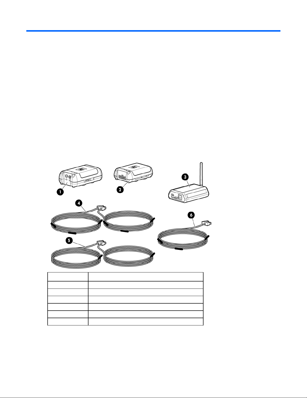
Callout Component
1
2
3
4
5
6
Consult your data center administrator for detailed placement and configuration information.
HP Air Pressure Base Station
HP Environmental Base Station
HP Base Station Gateway
HP Rack Sensor Array
HP Plenum Rated Sensor Array
HP Three Point Sensor Array
HP Data Center Environmental Edge hardware overview 5
Page 6

Required tools
The following items are required for installation:
• HP Environmental Edge Installer Kit
• Ladder
• Floor tile suction lifter
• Perforated floor tile lifter
• Battery-operated label maker with:
o Spare batteries
o Spare ribbon
• USB barcode scanner
• Small wire cutting pliers
• 18-30 AWG wire strippers
• No. 1 Phillips screwdriver
• 1/8-inch standard flathead screwdriver
• CAT5e Ethernet cable
HP Environmental Edge Installer Kit
The installer kit is provided to ease installation of the hardware components.
NOTE: Most installations do not use all items included in the Mounting Supplies Kit. Do not
The following items are included in the HP Environmental Edge Installer Kit:
• 6-in zip ties (bag of 100)
• 7-in zip ties (bag of 100)
• Thermistor sensor mounting clips (100)
• Cable restraint clips
• Command strips (100)
• Double-sided tape
• Mounting tape liner
• Labels
• Alcohol wipes
discard these items.
For more information, see the HP Data Center Environmental Edge Installation Kit Information document.
HP Data Center Environmental Edge hardware overview 6
Page 7

HP Base Station Gateway
Overview: Gateway
The gateway collects information from all wireless base stations within a wireless network and sends the
information to the HP Insight Environmental Observer software over an Ethernet connection.
Only one instance of the HP Insight Environmental Observer software can connect to a gateway device,
though it can connect to multiple gateways within the data center, depending on the available network
connection.
Configuring the HP Base Station Gateway
NOTE: The default IP address for each gateway is 192.168.0.2.
Each installed gateway must have a static IP address. Configure the gateway IP address, using the same
address assigned to the gateway in the HP Insight Environmental Configurator, before you install the
gateway and connect to the network. For more information, see the HP Insight Environmental Configurator
User Guide. Consult your data center administrator to obtain gateway IP addresses.
To configure the gateway:
1. Connect one end of the supplied power cable to the gateway and the other end to a power source.
2. Connect one end of the CAT5 Ethernet cable to the gateway and the other end to the computer from
which you will configure the gateway.
HP Base Station Gateway 7
Page 8
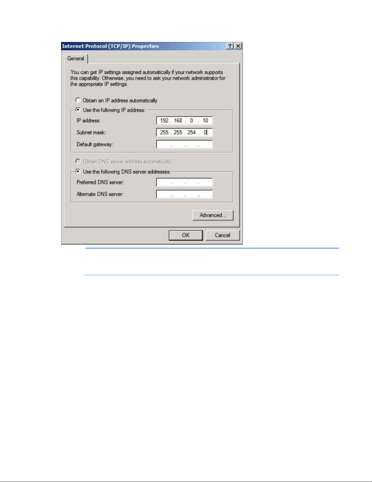
3.
Configure the IP address of the computer to a temporary static address such as 192.168.0.10.
NOTE: You only need to set the IP address to a static address of the configuring computer during
the configuration of the gateway. When you complete the configuration, restore your original
4. Open your web browser, and in the URL address box, type in the default gateway address:
network settings.
http://192.168.0.2
The Lantronix Web Manager Login window appears.
5. Enter the case-sensitive user name and password.
o The default user name is admin.
HP Base Station Gateway 8
Page 9
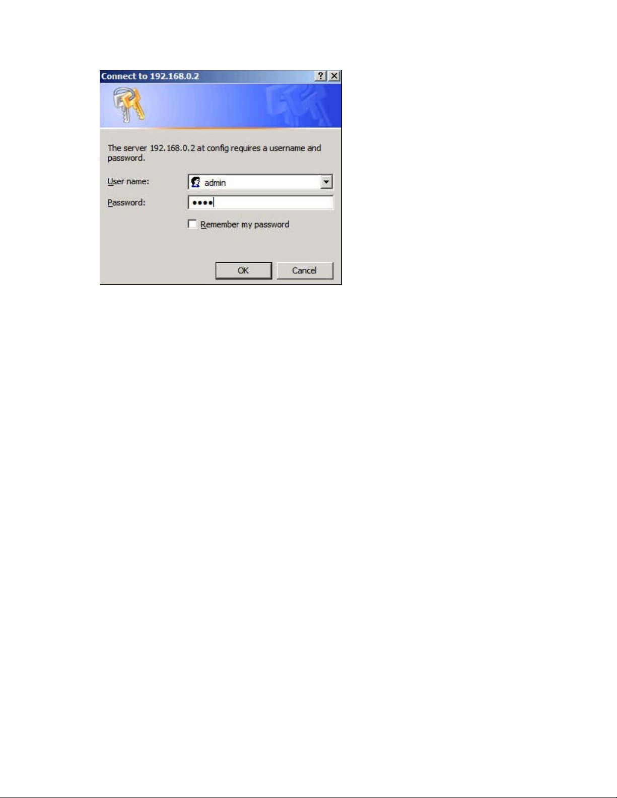
The default password is PASS.
o
HP Base Station Gateway 9
Page 10
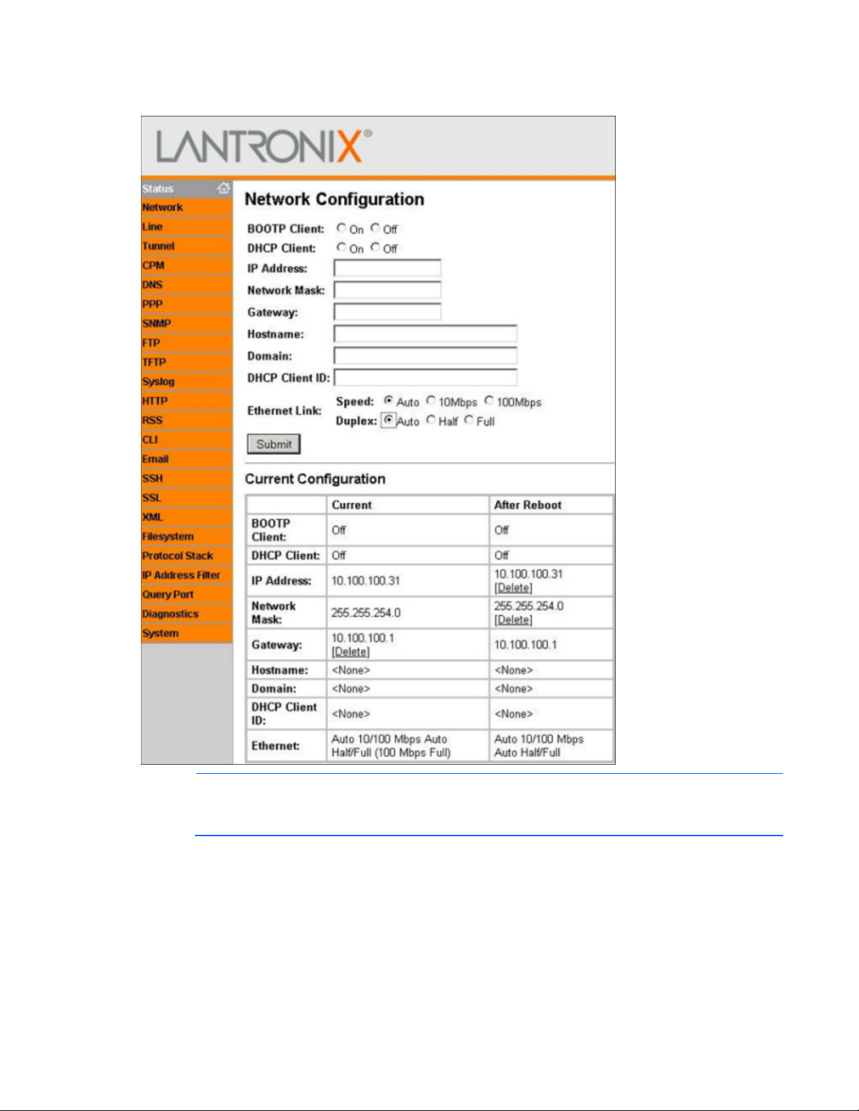
6.
In the navigation menu on left side of the page, select Network. The Network Configuration page
appears.
NOTE: The Ethernet link settings of speed and duplex must match the settings of the switch and
servers NIC. If the speeds or duplex do not match, then the gateway cannot communicate with the
7. Populate the following fields, using the same information you entered in the HP Insight Environmental
Edge server.
Configurator:
o IP address (Example: 10.100.100.30)
o Network mask (Example: 255.255.254.0)
o Gateway (Example: 10.100.100.1)
8. Select Submit.
9. Verify the default settings on the following pages:
HP Base Station Gateway 10
Page 11

o
Device Status page
HP Base Station Gateway 11
Page 12
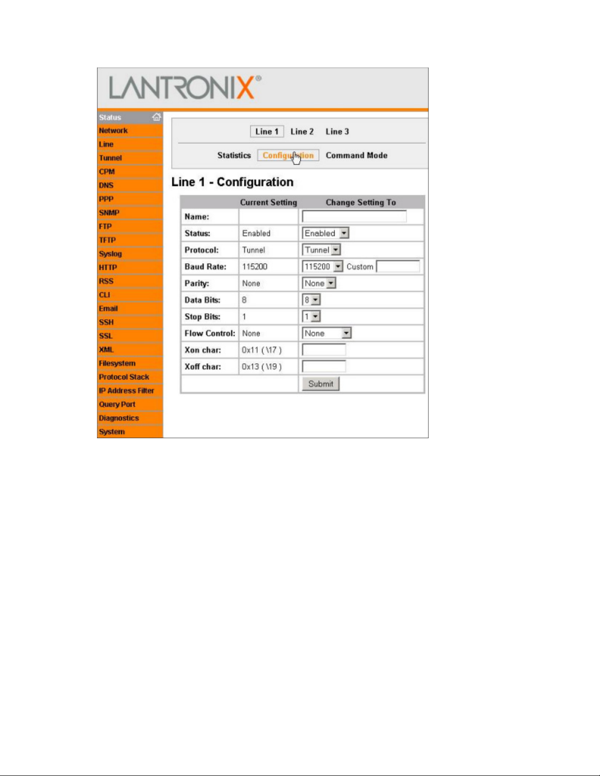
o
Line 1 Configuration page
HP Base Station Gateway 12
Page 13

o
Tunnel 1 Serial Settings page
HP Base Station Gateway 13
Page 14

o
Tunnel 1 Accept Mode page
HP Base Station Gateway 14
Page 15

o
Tunnel 1 Connect Mode page
HP Base Station Gateway 15
Page 16

10.
In the navigation menu on the left side of the page, select System. The System page appears.
11. Select Reboot. The confirmation window appears.
12. Select OK. The gateway reboots, and the new configured parameters take effect.
13. Repeat steps 1 through 11 for all gateways, using each unique IP address used in the HP Insight
Environmental Configurator.
14. Restore the original network settings on your computer.
Installing the HP Base Station Gateway
NOTE: Consult your data center administrator to determine the location for the gateway that
1. Determine the location for the gateway in your data center.
2. Ensure the location is free from dust before installing the gateway.
optimizes the wireless range for all base stations.
HP Base Station Gateway 16
Page 17

3.
Insert and tighten the antenna to the gateway.
4. Remove the mounting tape liner, and secure the gateway to the desired location.
5. Connect one end of the supplied power cable to the gateway and the other end to a power source.
HP Base Station Gateway 17
Page 18

6.
Connect one end of the CAT5 Ethernet cable to the gateway and the other end to your network.
7. Turn on the gateway by flipping the power switch.
8. Verify that the gateway is connected to power and is working in operation mode by viewing the
gateway LED status (on page 18).
o Connected—The gateway Active LED is either flashing or solid green and the Battery LED is off.
o Not connected—The gateway Battery LED is either flashing or solid red.
Installation is complete.
Gateway LED status
The HP Base Station Gateway has the following LEDs:
• Battery LED
o Flashes red if the gateway is not connected to power and is running on batteries.
HP Base Station Gateway 18
Page 19

o
Is solid red if the gateway is not connected to the network or if HP Insight Environmental Observer
application is not running.
• Active LED
o Flashes green if the gateway is communicating and active.
o Is solid green is the gateway is connected properly and is working in operating mode.
HP Base Station Gateway 19
Page 20

HP Environmental Base Station installed on a rack
Overview: Installing a base station on a rack
The base station is a wireless device that collects temperature data from the external sensor arrays and sends
the information to the gateway. The base station has its own internal temperature and humidity sensors and
collects data to send to the gateway.
When the base station is installed on a rack, it is attached to either the HP Rack Sensor Array or the HP Three
Point Sensor Array. The base station sends its internal temperature and humidity readings and the external
temperature readings from the sensor arrays to the gateway.
Each sensor array is composed of sensor pods. Each pod has a thermistor that collects temperature data for
a specific location. The sensor array is connected to the HP Environmental Base Station, which collects all
thermistor readings and sends the readings to the gateway.
Two types of sensor arrays can be installed on the rack:
• HP Rack Sensor Array—The array is composed of six sensor pods. The array is designed for installation
on a rack. Three thermistors are on the front rack door of a cold aisle, and three thermistors are on the
rear rack door of a hot aisle.
• HP Three Point Sensor Array—The array is composed of three sensor pods. The array is designed for
installation on the front rack door of a cold aisle, hanging from a wall, or installed at the end of a rack
row.
You can install the sensor arrays on the inside of perforated rack doors or the outside of any rack doors. HP
recommends installing the sensor arrays on the inside of the rack doors, if possible.
NOTE: If your rack does not have a door, HP recommends installing the sensor array on the front
left rail of the rack.
NOTE: If you have hot air recirculation issues, then install an HP Three Point Sensor Array at the
end of your rack row to help identify the problem location.
Installing the HP Environmental Base Station on a rack
Installing the HP Rack Sensor Array or HP Three Point Sensor Array
1. Ensure the rack doors are free from dust before installing the sensor array.
NOTE: The sensor array has labels that indicate the location where the array string must be
2. Verify that you are installing the correct sensor string to the correct side of the rack.
installed. Before installation, verify that you are installing the array string to the correct location.
HP Environmental Base Station installed on a rack 20
Page 21

o
The preconfigured lengths between the sensor pods are designed to fit a standard 42U
The HP Rack Sensor Array has the Front (Cold) Side label and the Rear (Hot) Side label, indicating
where the sensor string is installed.
o The HP Three Point Sensor Array does not have a label and can be installed anywhere on the rack
or in the data center.
NOTE:
rack and should be evenly spaced: one at the top of the rack door, one in the middle of the rack
door, and one at the bottom of the rack door. If you are installing the sensor pods on a rack of a
3. Remove the mounting tape liner and attach the top pod bracket to the designated location. Repeat this
different size and require an extension, consult your data center administrator.
step for the remaining two pod brackets.
4. If the sensor pod is not connected to the pod bracket, slide the top sensor pod into the pod bracket
installed at the top of the rack door (3). Repeat this step for the remaining two pods.
HP Environmental Base Station installed on a rack 21
Page 22

5. Remove the mounting tape liner and attach the cable restraint brackets near the door hinges on the
rack.
NOTE: The disconnect connector on the sensor array enables you to remove the rack door for
maintenance without having to uninstall the HP Environmental Base Station.
6. Using a cable tie wrap, secure any excess cabling.
7. If you are installing the HP Rack Sensor Array, repeat the previous steps for the rear door.
Installing the HP Environmental Base Station
HP Environmental Base Station installed on a rack 22
Page 23

NOTE: You can install the base station outside or inside of the top of the rack.
1. Ensure the area on the top of the rack is free from dust before installing the base station.
2. Remove the mounting tape liner, and secure the base station to the desired location on the top of the
rack.
3. Connect the data transfer cable from the HP Rack Sensor Array or HP Three Point Sensor Array to the
base station.
4. After all hardware is installed, power up the components ("Power up procedure" on page 70).
HP Environmental Base Station installed on a rack 23
Page 24

Installation is complete.
HP Environmental Base Station installed on a rack 24
Page 25

HP Environmental Base Station installed on a
The CRAH/CRAC must be powered down and the fans must be stopped before you
CRAH/CRAC
Overview: Installing a base station on a CRAH/CRAC
The base station is a wireless device that collects temperature data from the external sensor arrays and sends
the information to the gateway. The base station also has its own internal temperature and humidity sensors
and collects data of its own to send to the gateway.
When the base station is installed on a CRAH/CRAC, it is attached to the HP Plenum Rated Sensor Array,
and sends its own internal temperature readings and the external temperature reading from the sensor arrays
to the gateway.
The sensor array is composed of sensor pods, each with a thermistor that collects temperature data for a
specific location. The sensor array is connected to the HP Environmental Base Station, which collects the
thermistor readings and sends the readings to the gateway.
The HP Plenum Rated Sensor Array is composed of two sensor pods, one that measures the temperature at the
supply side of the CRAH/CRAC, and one that measures the temperature at the return side of the
CRAH/CRAC.
There are two CRAH/CRAC installation configuration options:
• Single—(Standard installation configuration) The base station measures temperature and humidity on
the supply side of the CRAH/CRAC and measures only temperature on the return side of the
CRAH/CRAC.
• Dual—(Optional installation configuration) The base station measures temperature and humidity on
both the supply and return side of the CRAH/CRAC. The return air temperature is an average of six
thermistor readings.
Installing the HP Environmental CRAH/CRAC (Single) Base Station
WARNING:
Installing the HP Plenum Rated Sensor Array
1. Ensure the desired installation locations around the CRAH/CRAC are free of dust before installing the
access the return plenum for hardware installation.
sensor array.
NOTE: The sensor array has labels that indicate the location where the array string must be
installed. Before installation, verify that you are installing the array string to the correct location.
HP Environmental Base Station installed on a CRAH/CRAC 25
Page 26

2.
Verify that you are installing the correct sensor string to the correct location in the CRAH/CRAC. The
CRAH Supply side is routed to the supply side of the CRAH/CRAC, and the CRAH Return side is routed
to the return side of the CRAH/CRAC.
3. Route and install the supply sensor. HP recommends installing the supply sensor to a support beam
under the sub-floor in front of the CRAH/CRAC. Consult your data center administrator for the exact
location for installation.
a. Remove the mounting tape liner and secure the supply sensor bracket to the designated location in
the supply air stream of the CRAH/CRAC.
b. Using a cable tie, secure the sensor bracket and any remaining cable.
4. Route and install the return sensor. HP recommends installing the return sensor to a flat surface inside of
the CRAH/CRAC. Consult your data center administrator for the exact location for installation.
a. Remove the mounting tape liner and secure the return sensor bracket to the designated location in
the return air stream of the CRAH/CRAC.
b. Using a cable tie, secure the sensor bracket and any remaining cable.
Installing the HP Environmental Base Station
1. Install the base station in an unobstructed location under the floor plenum in front of the CRAH/CRAC
supply air stream, to ensure accurate supply air humidity readings.
HP Environmental Base Station installed on a CRAH/CRAC 26
Page 27

HP recommends using cable tie wraps to secure the base station to an available support bracket.
2. Connect the data transfer cable from the HP Plenum Rated Sensor Array to the base station.
3. After all hardware is installed, power up the components ("Power up procedure" on page 70).
Installation is complete.
Single CRAH installation diagram
Callout Component Description
1
2
3
4
5
CRAH return air stream The return air side of the CRAH
CRAH supply air stream The supply air side of the CRAH
Base station The base station is mounted on the supply air side of the CRAH.
Supply side of plenum array The three-point plenum array that measures the supply air temperature
and humidity.
Return side of plenum array The three-point plenum array that measures the return air temperature
HP Environmental Base Station installed on a CRAH/CRAC 27
Page 28

Callout Component Description
The CRAH/CRAC must be powered down and the fans must be stopped before you
and humidity.
Installing the HP Environmental CRAH/CRAC (Dual) Base Station
The CRAH/CRAC (Dual) Base Station consists of:
• One base station for the supply air—Measures the supply air temperature and humidity
• One base station for the return air—Measures the return air temperature (the average of the six sensors
on the array) and humidity
Installing the HP Environmental Base Station in the supply air stream
1. Install the base station in an unobstructed location under the floor plenum in front of the CRAH/CRAC
supply air stream, to ensure accurate supply air humidity readings.
HP recommends using cable tie wraps to secure the base station to an available support bracket.
NOTE: Do not attach a sensor array to the base station in the supply air stream. The sensors that
measure the temperature and humidity are located inside the base station.
Installing the HP Environmental Base Station in the return air stream
WARNING:
access the return plenum for hardware installation.
1. Using the cable tie wraps, secure the base station to an unobstructed location or support beam in the
CRAH/CRAC return air stream.
2. Connect the data transfer cable from the HP Plenum Rated Sensor Array to the base station.
Installing the HP Plenum Rated Sensor Array in the CRAH/CRAC return air plenum
HP Environmental Base Station installed on a CRAH/CRAC 28
Page 29

WARNING: The CRAH/CRAC must be powered down and the fans must be stopped before you
access the return plenum for hardware installation.
1. Ensure the desired installation locations around the CRAH/CRAC are free of dust before installing the
sensor array.
NOTE: During installation of a CRAH/CRAC (dual) base station, ignore the Supply and Return
labels on the sensor array. All six sensors are installed in the return air stream.
2. Route and install the six sensors to a flat surface inside of the CRAH/CRAC, verifying that the air stream
is not obstructed. Consult your data center administrator for the exact location for installation.
a. Remove the mounting tape liner and secure the return sensor bracket to the designated location in
the return air stream of the CRAH/CRAC.
b. Using a cable tie, secure the sensor bracket and any remaining cable.
After all hardware is installed, power up the components ("Power up procedure" on page 70).
Installation is complete.
HP Environmental Base Station installed on a CRAH/CRAC 29
Page 30

Dual CRAH installation diagram
Callout Component Description
1
2
3
4
CRAH return air stream The return air side of the CRAH
CRAH supply air stream The supply air side of the CRAH
CRAH supply base station The base station is mounted on the supply air side of the
CRAH, and measures the supply air temperature and
humidity.
CRAH return base station and
plenum array
The base station is mounted on the return air side of the CRAH,
and attaches to the six-point plenum array that measures the
return air temperature and humidity.
HP Environmental Base Station installed on a CRAH/CRAC 30
Page 31

HP Air Pressure Base Station
Overview: Air Pressure Base Station
The air pressure base station is a wireless device that monitors the differential pressure across areas of the
data center and sends the information to the gateway.
The air pressure base station monitors and compares the difference between the pressure below the floor and
Installing the HP Air Pressure Base Station
the pressure above the floor.
1. Determine the location for the air pressure base station in your data center.
2. Cut one air tube so that it can reach from the air pressure base station to the area below the floor that
you want to monitor.
3. Cut the other air tube approximately 7-cm (3-inch) long.
4. Connect air diffusers to one end of each air tube.
NOTE: To receive accurate air pressure readings, avoid the following locations under the
sub-floor:
• Potentially turbulent air flow
• Support columns or beams
5. Install the long air tube. This tube monitors pressure in the desired area below the floor.
• Water pipes
a. Attach a flag label indicating the positive terminal to the long air tube.
b. Insert the long air tube into the positive terminal on the air pressure base station.
HP Air Pressure Base Station 31
Page 32

c.
Route the air tube to the area below the floor that you want to monitor.
d. Use cable tie wraps to secure the air tube to a support bracket below the floor.
6. Install the short air tube. This tube monitors the reference pressure above the floor.
a. Attach a flag label indicating the negative terminal to the short air tube.
b. Insert the short air tube into the negative terminal on the air pressure base station. The air tube sits
above the floor.
NOTE: HP recommends installing the base station below the floor tile, if possible.
7. Install the air pressure base station near a subfloor access location, so that the long air tube is routed
under the subfloor and the short air tube is above the floor.
o If a support bracket is available, use cable tie wraps to secure the base station to the support
bracket.
HP Air Pressure Base Station 32
Page 33

o
If there is a location behind and under a rack near subfloor access, use the double-sided mounting
tape to secure the air pressure base station to the floor tile near the subfloor access.
8. After all hardware is installed, power up the components ("Power up procedure" on page 70).
Installation is complete.
HP Air Pressure Base Station 33
Page 34

(Optional) Sensor Base Stations
Overview: (Optional) Sensor base stations
The optional sensor base stations enable HP approved third-party components to communicate wirelessly to
the gateways. The sensor base stations are considered optional depending on whether you want to monitor
other environmental data in your data center.
The connection between the data center component and the supplied sensor might require professional
installation. However, anyone can perform the installation to connect the sensor to the sensor base station.
You can install any of the following sensor base stations:
• HP Door Position Base Station—No professional installation required.
• HP Chilled Water Energy Meter Base Station—Facility technician installation required.
• HP Water Leak Detection Base Station—Facility technician installation required.
• HP Current Sensing Relay Base Station—Professional electrician installation required.
• HP 200A Current Base Station—Professional electrician installation required.
• HP KWH Base Station—Professional electrician installation required.
You can install the optional sensor base stations on most surfaces using the double-sided mounting tape.
Installing the HP Door Position Base Station
The HP Door Position Base Station connects to the supplied set of door sensors and detects and reports if the
door is open or closed. Ten sensors are located along a 15.2 m (50 ft) wire, which can be installed in a daisy
chain series with one another to monitor multiple doors.
To install a Door Position Base Station:
1. Ensure the area on the top of the rack is free from dust before installing the base station.
(Optional) Sensor Base Stations 34
Page 35

2.
Remove the mounting tape liner, and secure the base station to the desired location on the top of the
rack.
3. Remove the mounting tape liner, and secure the door position wire harness to the rack door.
4. Connect the Door Position Base Station to the door sensors.
a. Strip the plastic coating from the ends of the two door sensor wires.
b. Strip the plastic coating from the ends of the two wires on the Door Position Base Station wire
harness.
NOTE: If you are only installing one door position sensor, connect the second wire to the Door
Position Base Station. If you are installing the door position sensors in a daisy chain fashion,
connect the second wire to the next door position sensor.
c. Using a wire screw, twist together one wire from the door sensor with one wire from the Door
Position Base Station wire harness.
Repeat steps a through c for the other wire.
(Optional) Sensor Base Stations 35
Page 36

d.
Insert the connector from the Door Position Base Station wire harness into the Door Position Base
Station.
5. After all hardware is installed, power up the components ("Power up procedure" on page 70).
Installation is complete.
Installing the HP Chilled Water Energy Base Station
The HP Chilled Water Energy Base Station connects to the housing box, which contains an ultrasonic probe
sensor. The ultrasonic sensor measures and reports liquid flow through a chilled water pipe. Temperature
sensors are installed on the supply and return of the same chilled water pipe to measure the rise of the
temperature as chilled water enters and exits the data center room.
Consult a facility technician to install the ultrasonic probe sensor to your chilled water pipe.
To install the Chilled Water Energy Base Station:
1. Choose a location for the housing box, relatively close to the chilled water pipes.
a. If a flat surface is available, remove the mounting tape liner, and secure the housing box to the
surface.
(Optional) Sensor Base Stations 36
Page 37

b.
If a support bracket is available, use cable ties to secure the housing box to the support bracket.
2. Route the ultrasonic probe to the appropriate locations along the chilled water pipe.
3. Connect the housing box to the required sources.
Callout Component Description
1
2
3
4
5
4. After all hardware is installed, power up the components ("Power up procedure" on page 70).
Installation is complete.
Supply temperature Routed to the supply side of the chilled water pipe to measure temperature
Power connector Connected to AC power
Return temperature Routed to the return side of the chilled water pipe to measure temperature
Downstream flow meter Routed to the downstream of the chilled water pipe to measure flow rate
Upstream flow meter Routed to the upstream of the chilled water pipe to measure flow rate
(Optional) Sensor Base Stations 37
Page 38

Single Chilled Water installation diagram
Callout Component
1
2
3
4
5
6
7
Chilled Water Energy Base Station
Water supply line to the CRAH/CRAC
Water return line from the CRAH/CRAC
Water supply temperature sensor probe
Upstream flow meter
Water return temperature sensor probe
Downstream flow meter
Configuring the Chilled Water Base Station
NOTE: You must have the ULTRALINK™ software installed on the PC that is configuring the base
station. You can download the software from the Dynasonics website
(http://www.dynasonics.com/downloads.php).
(Optional) Sensor Base Stations 38
 Loading...