

Page 1

DAT 72 Models 5242 and 5242-ACL Tape Drive User's Guide
4mm Tape Drive for HP NonStop Servers
5242 Tape Drive 5242-ACL Tape Drive
Part Number: 528296-003
Release Version Updates (RVU) Support
G06.10 and all subsequent G-Series RVUs,
H06.03 and all subsequent H-Series RVUs,
Until otherwise indicated by its replacement publication
Hewlett Packard
19333 Vallco Parkway
Cupertino, CA 95014
© 2004 - 2005 HP
All rights reserved
No part of this document may be copied in any form or by any means without prior written consent of HP. EPROMs
used in the products described herein contain firmware that is copyrighted by and shall remain the property of HP.
All drawings, schematics and artwork used in the manufacture of the products described herein are copyrighted.
Reproduction of said drawings, schematics and artwork or manufacture of said products without written consent of
HP is absolutely prohibited.
Document History Part Number
528296-001 June 2004
528296-002 November 2004
528296-003 July 2005
Publish Date
HP StorageWorks DAT 72 (Models 5242 and 5242ACL) User's Guide HP Part Number 528296-003 July 2005
Page 2

i List of Acronyms
ACL Automated cartridge loader
ANSI American National Standard Institute
BOM Beginning of media
BOT Beginning of tape
FRU Field replaceable unit
DCLZ Data Compression Lempel Ziv
DDS Digital Data Storage
ECC Error correction code
EOD End of data
EOM End of media
FRU Field replaceable unit
LCD Liquid crystal display
LED Light emitting diode
SCSI Small Computer Systems Interface
ii Terminology Used in This Manual
Autoloader A device that includes a tape drive and a cartridge changer mechanism in a single case.
Emulator The SCSI bridge between the host and the tape drive that provides intelligence to execute
commands to the tape drive and manipulate data for display on the LCD.
Initiator A SCSI device that initiates the SCSI protocol to control one or many target devices.
DAT72 Bare 3.5 inch 4mm DDS fifth generation tape drive.
Target Receiver of the SCSI commands sent by an initiator. Target peripheral devices include
tape drives, tape drive robotics, disk drives, optical scanners, and so on.
iii Assumptions About Reader Knowledge
This manual assumes that the reader is familiar with:
• The operational principles of tape drives.
• The Small Computer Systems Interface (SCSI).
iv Safety Summary
Observe the following safety precautions during installation, operation and maintenance.
Warning
Keep away from live circuits. Do not connect the tape drive or make adjustments inside the equipment when the
unit's power cord is connected. Voltages exist even when the power switch is in the off position. Always disconnect
the power cord before removing the cover or touching any internal components.
CAUTION
Any changes or modifications to the equipment by the user not expressly approved by the grantee or manufacturer
could void user's authority to operate such equipment.
HP StorageWorks DAT 72 (Models 5242 and 5242ACL) User's Guide HP Part Number 528296-003 July 2005
Page 3

v Table of Contents
Section 1 – General Information
Chapter One
Chapter Two
Chapter Three
Chapter Four
Chapter Five
Chapter Six
Section 2 – 5242 Tape Drive
Chapter One
Chapter Two
Chapter Three
Chapter Four
......................................................................................………………………….1
Introduction.........................................................................………………………….1
Applications........................................................................………………………….1
Software Prerequisites.........................................................………………………….1
SCSI Cables ........................................................................………………………….1
Component Part Numbers...................................................………………………….2
Cartridges............................................................................………………………….2
Write-Protecting a Cartridge...............................................………………………….3
Labeled and Unlabeled Tapes.............................................………………………….3
Features...............................................................................………………………….3
......................................................................................………………………….5
SCSI Compatibility.............................................................………………………….5
DAT72 Format and Compatibility......................................………………………….5
....................................................................................………………………….6
Installing the 5242 and 5242-ACL on Nonstop Servers……………………….…….6
Installation Overview..........................................................………………………….6
Installation Planning ......................................................………………………….7
Physical Specifications ..................................................………………………….7
Environment Specifications ...........................................………………………….7
AC Power Requirements................................................………………………….8
Unpacking......................................................................………………………….9
Installing the Tape Drive................................................…………………………10
Connecting the SCSI Cable............................................…………………………11
Bringing the Tape Drive Online.....................................…………………………12
5242 Power-Up Sequence..............................................…………………………13
5242-ACL Power-Up Sequence.....................................…………………………14
Checking and Setting SCSI the ID.................................…………………………15
Starting and Testing .......................................................…………………………17
Troubleshooting .............................................................…………………………18
Configuring the 5242 and 5242-ACL for Nonstop Servers.…………………………19
......................................................................................…………………………24
Preventive Maintenance......................................................…………………………24
5242 Tape Path Cleaning....................................................…………………………24
5242-ACL Tape Path Cleaning...........................................…………………………25
Cleaning the Exterior ..........................................................…………………………26
Operating Environment.......................................................…………………………26
......................................................................................…………………………27
Technical Support ...............................................................…………………………27
........................................................................................…………………………28
Cabling Limitations.............................................................…………………………28
Differential Devices............................................................…………………………28
Cooling Fan and System .....................................................…………………………28
Specifications......................................................................…………………………28
......................................................................................…………………………30
Introduction.........................................................................…………………………30
Features...............................................................................…………………………30
......................................................................................…………………………31
Loading and Unloading a Cartridge....................................…………………………31
....................................................................................…………………………32
Controls and Indicators.......................................................…………………………32
Understanding the LEDs.....................................................…………………………32
......................................................................................…………………………34
Upgrading the Firmware From Tape...................................…………………………34
HP StorageWorks DAT 72 (Models 5242 and 5242ACL) User's Guide HP Part Number 528296-003 July 2005
Page 4

Section 3 – 5242-ACL Tape Drive
Chapter One
......................................................................................…………………………35
Introduction.........................................................................…………………………35
Features...............................................................................…………………………35
Chapter Two
......................................................................................…………………………36
Mode of Operation..............................................................…………………………36
Terminology........................................................................…………………………36
Front Panel Buttons.............................................................…………………………36
Loading and Unloading the Magazine and Cartridges........…………………………37
Ejecting the Magazine and Cartridges ................................…………………………38
Forcing a Tape to Eject.......................................................…………………………39
Front Panel LEDs................................................................…………………………39
Self-Test Display ................................................................…………………………40
Chapter Three
....................................................................................…………………………41
Display Regions on the Autoloader LCD ...........................…………………………41
Diagnostic Display..............................................................…………………………41
LCD Categories of Information ..........................................…………………………41
LCD Messages....................................................................…………………………43
Chapter Four
......................................................................................…………………………49
Upgrading Firmware...........................................................…………………………49
Section 4 – SCSI Electronics
Chapter One
......................................................................................…………………………50
Controls and Indicators.......................................................…………………………50
Mode Switch.......................................................................…………………………50
LEDs ...................................................................................…………………………50
Front Panel LCD.................................................................…………………………51
Understanding the Capacity Bar Graph ..............................…………………………51
Chapter Two
......................................................................................…………………………51
Introduction.........................................................................…………………………51
Initial LCD..........................................................................…………………………52
Performance LCD Format...................................................…………………………52
Setting Tape Density...........................................................…………………………55
Setup Display Format..........................................................…………………………55
Setup 1 Configuration Display Format ...............................…………………………58
Setup 2 Configuration Display Format Items......................…………………………61
Setup 3 Off-Line Utilities Display Format Items................…………………………62
Section 5 – Index and Safety
..................................................................................................…………………………68
Index
Safety and Compliance
......................................................................…………………………70
HP StorageWorks DAT 72 (Models 5242 and 5242ACL) User's Guide HP Part Number 528296-003 July 2005
Page 5

viii About This Manual
This manual provides installation, operation, and maintenance Instructions for the 5242 and 5242-ACL tape drives.
This guide first presents information common to both units and then provides product-specific information.
Section I Provides information that applies to both the 5242 and the 5242-ACL tape drive.
Section II Provides a detailed description of the 5242 tape drive
Section III Provides a detailed description of the 5242-ACL tape drive
Section IV Explains the electronics that execute SCSI commands to the tape drive and that provide
performance and statistical information to the LCD.
HP StorageWorks DAT 72 (Models 5242 and 5242ACL) User's Guide HP Part Number 528296-003 July 2005
Page 6
CLEAN TAPE HEADS
To maintain optimum performance and to prevent READ/WRITE errors, clean the tape heads of the 5242 and 5242ACL tape drive on a regular basis. Use the cleaning schedule noted in Table 1.
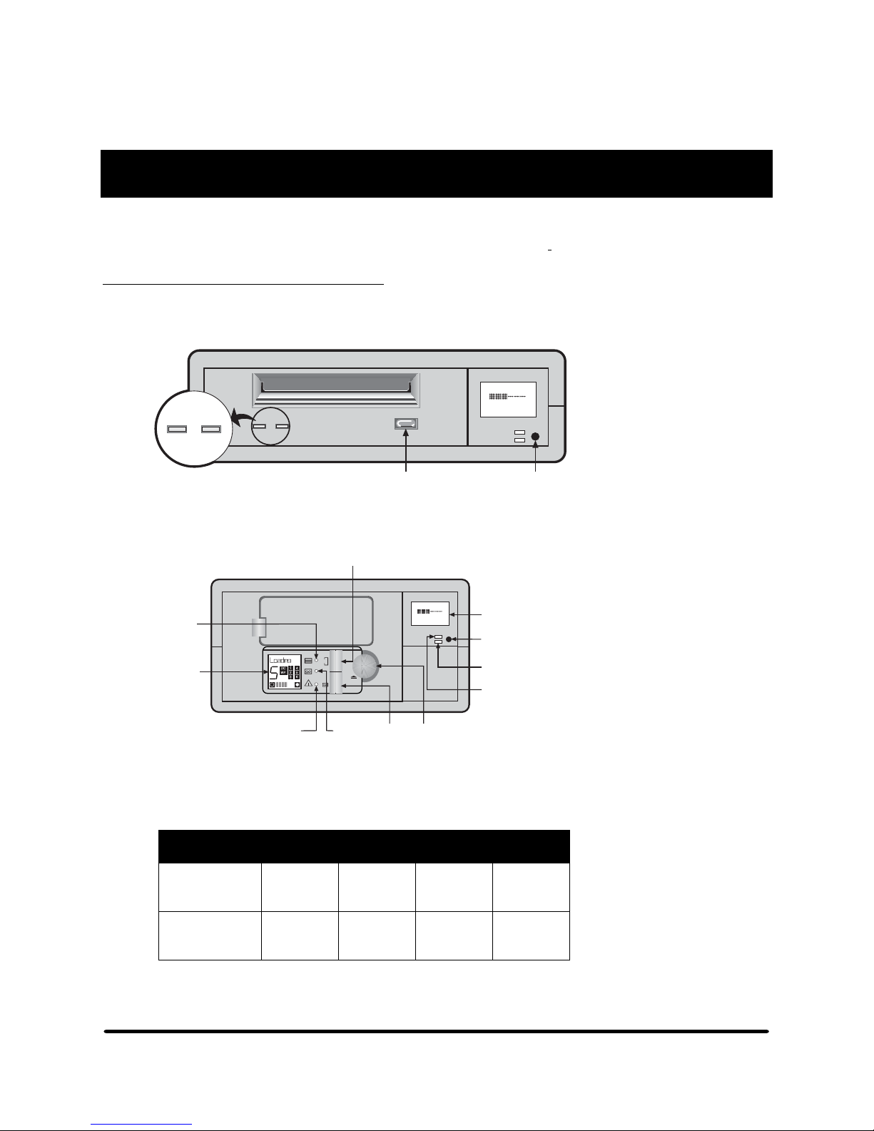
5242 and 5242-ACL Tape Path Cleaning
The Clean/Attention LED is located on the front panel of the tape drive. When it flashes amber, the tape
heads are dirty and need to be cleaned.
Write
E F
COMPRESS
Tape Clean/
Attn.
12
12
2.3:1
Detail
A
Eject
Button
Mode
Switch
Figure 1 5242 Clean/Attention LED
Magazine
Present
LED
Autoloader
LCD
Operator
Attention
Required
LED
Select Button
6
Eject
Tape
Activity
LED
Load
Tape
Button
Write
E F
COMPRESS
2.3:1
Eject
Button
4-Line LCD,
8-Characters per line
Mode
Switch
Programmable
Error-Alert LED
Compression
Indicator LED
Figure 2 5242-ACL Autoloader's front panel
Recommended Cleaning Schedule for
125m DDS-3 and 170m DAT72 Tape Cartridges
Number of
tape cartridges
used each day
Recommended
Cleaning
Frequency
Table 1 Cleaning schedule for the 5242 when using DDS-3 and DAT72 tape cartridges
1 2 3 4 or more
8 weeks 4 weeks 3 weeks Weekly
HP StorageWorks DAT 72 (Models 5242 and 5242ACL) User's Guide HP Part Number 528296-003 July 2005
Page 7

Using the Cleaning Cartridge
: To prevent contamination of the subsystem and damage to the heads (1) do not use the cleaning
Note
cartridge for more than the manufacturer's specified number of cleaning cycles; and (2) do not
attempt to rewind the material in the cleaning cartridge and reuse it.
Insert the cleaning cartridge into the drive. The drive automatically takes the cartridge, loads it and
cleans the heads. After about 30 seconds, the drive ejects the cartridge.
: If the cartridge ejects after only about 14 seconds, this means the cartridge has reached the end of its
Note
useful life, and no cleaning has occurred. The Cleaning Needed LED may still be illuminated. If this
happens, discard the cartridge and with a new cleaning cartridge, repeat the cleaning operation.
Take the cartridge out of the drive. Write the date on the label of the cleaning cartridge so that there
is a record of how many times it has been used. Do not use the cleaning cartridge more times than
specified by the manufacturer.
HP StorageWorks DAT 72 (Models 5242 and 5242ACL) User's Guide HP Part Number 528296-003 July 2005
Page 8

Section 1: General Information
General Information
1.1 Introduction
Both the 5242 and 5242-ACL tape drives use helical scan tape technology and offer full read-and-write
capability. They come in tabletop configurations that integrate a tape drive, status display, and highperformance SCSI electronics.
With a steel chassis and a sturdy ABS plastic shell, the 5242 and 5242-ACL provide optimal performance in
many environments. Place units on top of each other like stereo components or line them up like books on a
shelf. The modules interlock securely for stability. With individual power supplies, they are self-contained and
independently field replaceable units (FRUs).
1.2 Applications
The 5242 and the 5242-ACL are typically used as backup devices to prevent data loss from human error
and hardware failures. They also support other tape applications such as:
• Archive data
• NonStop s-series SIT / SUT distribution
• File inquiry and update
• Distribution and exchange of data and software
1.3 Software Prerequisites
• G06.23 or later versions of OSM are required for HP NonStop S-series servers
• H06.03 or later versions of OSM are required for HP Integrity NonStop servers
• 5242 and 5242-ACL tape drives are supported on G06.10 through G06.22 by installing the G06.23 or
later version of OSM and the appropriate software product revisions (SPRs). See prerequisite SPRs for
OSM In the OSM Migration Guide for G06.23 or later.
1.4 SCSI Cable
A copper SCSI cable is used to connect the tape drive FRU to a NonStop server. One end of the cable has a
68-pin connector with thumb screws that connect to the uncapped SCSI port at the rear of the tape drive.
The other end of the cable also has a 68-pin connector with thumbscrews that connects to the NonStop Sseries differential SCSI port or to the HP M8201fibre channel to M8201 Fibre Channel to HVD SCSI
router on Integrity NonStop servers. Connectivity is supported for Integrity NonStop servers via
attachment to a NonStop S-series I/O enclosure. Copper SCSI cable lengths can range from 10 feet (3
meters) to 75 feet (23 meters).
: The 5242 and 5242-ACL tape drives do not include a SCSI Cable. HP offers a variety of
Note
SCSI cable lengths . For HP cable information, see section 6.1 on page 28.
Section 1
Chapter One
HP StorageWorks DAT 72 (Models 5242 and 5242ACL) User's Guide 1 HP Part Number 528296-003 July 2005
Page 9

Section 1: General Information
1.5 Tape Drive Part Numbers
Description Part Number
5242 tape drive FRU 528078-001
5242-ACL tape drive FRU 528079-001
Each tape drive includes:
Terminator, 68-pin
170m DAT72 data cartridge
Cleaning tape
User documentation (CD)
Table 2 Tape drive part numbers
1.6 Cartridges
A cartridge is a storage device that contains either magnetic tape or a cleaning ribbon inside a protective
case. The cartridge protects the tape or ribbon and makes handling easier. The two types of cartridges:
(1) cleaning cartridges and (2) cartridge tapes.
1.6.1. Cleaning Tapes
Cleaning cartridges are used to clean the recording heads of the tape drive with a cleaning ribbon.
1.6.2 Cartridge Tapes
Cartridge tapes hold magnetic storage media for the tape drive. A cartridge tape is a self-contained
plastic shell containing a spool of magnetic tape. These cartridges are used to record and read back
system data.
1.6.3 Humidity
To avoid condensation problems, allow a tape to stabilize at least two hours after a change in
humidity or temperature before using.
1.6.4 Life Expectancy of Tapes
DDS-certified media is electronically checked to withstand at least 2000 passes. Under optimum
environmental conditions (50% relative humidity, 22ºC), this is equivalent to about 200 to 300
backup operations. This rating takes into account that an area of tape might have several passes
during a backup. Sustained use at the low end of the humidity specification reduces the tape life.
1.6.5 Using Labels
Cartridge and magazine labels must be firmly stuck to the recessed label area and nowhere else.
To avoid a mechanism jam:
• Labels must be firmly stuck and not peeling off or curling at the corners.
• Labels must be stuck only within the label area.
• A label must not be stuck on top of another label.
• Only use the labels that are supplied with the cartridges or magazine.
HP StorageWorks DAT 72 (Models 5242 and 5242ACL) User's Guide 2 HP Part Number 528296-003 July 2005
Page 10
Section 1: General Information
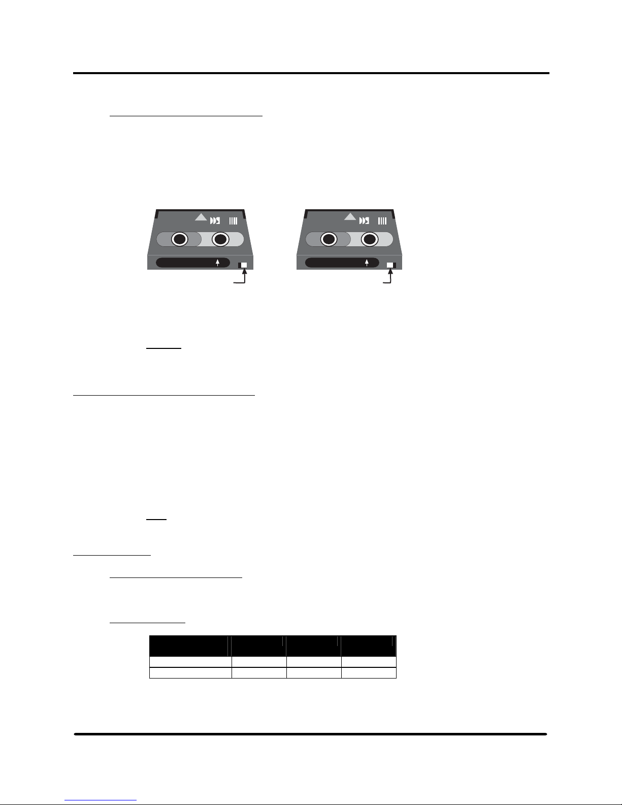
1.6.6 Write-Protecting a Cartridge
The tape cartridge has a write-protect switch that protects data cartridges from being overwritten.
To protect the cartridge, slide the switch all the way to the left. The hole will be visible. Data can
then be read from the tape but not written to it. Slide the switch to the right (covering the hole) to
write-enable the cartridge. Data can be written to and read from the tape.
Cartridge to be Loaded
in this Orientation
Cartridge to be Loaded
in this Orientation
Digital
Data
Storag
Label Side Up
Write Enabled
White Switch to the Right
Label Side Up
Write Protected
White Switch to the Left
Figure 3 Write-protecting a cartridge
Caution
: The tape log, which contains a history of usage of the tape, is not updated when
the cartridge is write-protected. The tape log is invalid if a cartridge is used
when write-protected.
1.7 Labeled and Unlabeled Tapes
The 5242 and 5242-ACL tape drives can use both labeled and unlabeled cartridge tapes. A tape
label is a record at the beginning of a tape that identifies the tape volume and the files it contains.
An expiration date protects labeled-tape information from being accidentally overwritten. A
scratch tape is a labeled tape with an expiration data that has passed. If a tape has no standard
label, it is considered unlabeled. Nonstop servers support two standard tape-label formats:
ANSI
IBM-MVS
: Because they can be cataloged and offer security features for protecting data, labeled tapes
Note
should be used with the 5242 and 5242-ACL tape drives.
1.8 Features
1.8.1 Recording Technology:
Helical scan tchnology
18.2 Capacity:
Typical Native Data
Capacity
125m cartridge DDS-3 12.0 GB 72.0 GB
170m cartridge DAT72 36.0 GB 216.0 GB
Table 3 Tape cartridge capacities
Drive Type 5242 5242-ACL
Digital
Data
Storag
HP StorageWorks DAT 72 (Models 5242 and 5242ACL) User's Guide 3 HP Part Number 528296-003 July 2005
Page 11

Section 1: General Information
1.8.3 SCSI bus data transfer rates (sustained):
• 3.0 MB/s uncompressed
• 6.0 MB/s compressed
1.8.4 SCSI bus data transfer rates (burst):
• 3.0 Mb/s asynchronous
• 10.0 Mb/s synchronous
1.8.5 Interface:
• SCSI-3, high-voltage differential
1.8.6 LCD status display and control panel include:
• Intelligent front end, backlit, supertwist LCD
• Advanced drive test and exercise function
• Firmware upgrade function
HP StorageWorks DAT 72 (Models 5242 and 5242ACL) User's Guide 4 HP Part Number 528296-003 July 2005
Page 12

Section 1: General Information
Chapter Two
2.1 SCSI Compatibility
5242 and 5242-ACL tape drives comply with the American National Standard Institute (ANSI) standard
X3.131-1986 (SCSI-1) and the ANSI standard X3T9.2 (SCSI-2). These standards define the specifications for
the Small Computer System Interface (SCSI). As defined by the ANSI, SCSI is essentially an input/output
bus for interconnecting computers and peripherals.
2.2 DAT72 Format and Compatibility
5242 and 5242ACL DAT72 format is an extension of the DDS-3 format. DDS formats have been developed
to provide data storage for computers by using and extending DAT technology. DAT72 allows 36 GB of
uncompressed data to be stored on a DAT72 (170m) cartridge. Data compression can increase the cartridges
native capacity. A compression ratio of 2:1 raises the capacity of the cartridge to 72 GB.
• The DAT72 format allows compressed data to be stored in a way that maintains the full functionality
of the DDS-3 format and ensures backward compatibility in reading and writing with existing 5142
and 5142ACL DDS-3 tape drives.
• The drive automatically decompresses data even if data compression is switched off.
• DDS-3 tapes written on a DAT72 drive are readable on a DDS-3 drive; however, a DAT72 tape (170
meters) is not readable on a DDS-3 drive. A DDS-3 drive (both single drive and ACL models)
automatically ejects a DAT72 cartridge. An ACL unit ejects the cartridge into the magazine but does not
unload the magazine. Additionally, the ACL displays: TAPE FAULT: TRY NEW TAPE.
• The DAT72 format uses the same error correction techniques as the DDS-3 format. It incorporates the
error correction techniques used in DAT drives with additional techniques designed to provide superior
data integrity.
HP StorageWorks DAT 72 (Models 5242 and 5242-ACL) User's Guide 5 HP Part Number 528296-03 July 2005
Page 13

Section 1: General Information
Chapter Three
3.1 Installing the 5242 and 5242-ACL Tape Drives on Nonstop Servers
This chapter describes how to plan for and install the 5242 and 5242ACL tape drives:
• Installation overview
• Installation planning
• Unpacking the 5242 and 5242-ACL tape drives
• Installing a 5242 or 5242-ACL tape drives
• Starting and Testing the 5242 and 5242-ACL tape drives
• Troubleshooting the 5242 and 5242-ACL tape drives
3.2 Installation Overview
This table summarizes the tasks involved in installing a 5242 or 5242-ACL tape drive on a NonStop server:
Task Description See these headings
1. Plan for the installation. Installation Planning
2. Unpack the 5242 or 5242-ACL
tape drive subsystems.
3. Connect the 5242 or 5242-ACL
tape drive to the NonStop server.
4. Use SCF to add the 5242 or
5242-ACL tape drive to your
configuration.
5. Bring the 5242 or 5242-ACL
tape drive online.
6. Verify or set the SCSI ID for the
5242 or 5242-ACL tape drive.
7. Verify that the 5242 or 5242-ACL
tape drive is ready for use.
Table 4 Summary of the tasks for installing the 5242 or 5242-ACL tape drives
3.2.1 Installation Planning
If connecting the 5242 or 5242-ACL tape drive to a previously installed NonStop server or to a new
NonStop server, review the following information about site planning, power requirements and cable
considerations before beginning tape drive installation.
3.2.1.1 Service Clearance and Dimensions
Note the following positioning and size information before beginning the installation:
• The 5242 and 5242-ACL requires 23 by 33 centimeters (9 inches by 13 inches) of space.
• Allow clearance of 31 centimeters to 46 centimeters (12 inches to 18 inches) at the front and 31
centimeters (12 inches) at the rear of each tape drive for adequate ventilation and servicing.
3.2.1.2 Physical Specifications
• 5242 dimensions:
•L292mm x W211mm x H64mm
•L11.5" x W8.3" x H2.5"
Unpacking the 5242 or 5242-ACL
tape drives.
Connecting the 5242 or 5242-ACL
tape drives to a NonStop server.
Configuring the 5242 or 5242-ACL
tape drive online using SCF.
Bringing the 5242 or 5242-ACL tape
drives online after installation.
Checking and setting the SCSI ID.
Starting and testing the 5242 and
5242-ACL tape.
HP StorageWorks DAT 72 (Models 5242 and 5242-ACL) User's Guide 6 HP Part Number 528296-03 July 2005
Page 14
Section 1: General Information
• 5242-ACL dimensions
•L292mm x W211mm x H107mm
•L11.5" x W8.3" x H4.2"
• The AC power cord measures 1.8 meters (6 feet).
• The maximum cable length for attaching a 5242 or 5242-ACL to a NonStop S-series
server, M8201 Fibre Channel to HVD SCSI router, or NonStop S-series I/O enclosure
is 25 meters (82 feet).
3.2.1.3 Environmental Requirements
Factor Operating (with
Temperature 5ºC to 40ºC -40ºC to 45ºC
Relative
Humidity
Acoustic Noise 28 dB N/A
tape loaded)
20% to 80% 5% to 95%
Table 5 Environmental requirements for the 5242 and 5242-ACL
Country/
Region
North America
(locking plug)
North America
(locking
receptacle)
Austria,
Belgium,
Finland, France,
Germany,
Netherlands,
Norway and
Sweden
Australia, New
Zealand
United Kingdom 10 250 BS-1363
Switzerland 10 250 SEV
Italy 10 250 CEI 23-16/VII
Denmark 10 250 Afsnit 107
Current
(Amps)
10 125 NEMA 5-15P
10 125 NEMA 5-15R
10 250 CEE 7/7
10 250 AS 3112
Voltage
(Volts)
Table 6 Current and voltage ratings of AC power cords available for the tape drive
Nonoperating
Plug
1011.1959
HP StorageWorks DAT 72 (Models 5242 and 5242-ACL) User's Guide 7 HP Part Number 528296-03 July 2005
Page 15
Section 1: General Information
3.2.1.4 AC Power Requirements
Each 5242 and 5242-ACL tape drive includes an auto ranging-power supply that accepts
input current in a voltage range of 115 volts AC to 230 volts AC at 50 hertz to 60 hertz. No
switch is required to change between ranges or between 50 hertz and 60 hertz.
: The power supply cannot be replaced as a subassembly. If the power supply fails,
Note
you must replace the entire tape drive.
Power Volts 5242
USA 60 Hz 110/120 0.6 1.0
Europe 50 Hz 220 0.3 0.5
Orient 50 Hz 200 0.3 0.5
Amperes
Table 7 AC power requirements for the tape drive
Each tape drive includes a 1.8-meter (6-foot) AC power cord. One end of the power cord
plugs in to the socket near the AC power switch at the rear of the tape drive. The other end
of the power cord is routed to the AC power source. (See Connecting and Routing the AC
Power Cords, page 10).
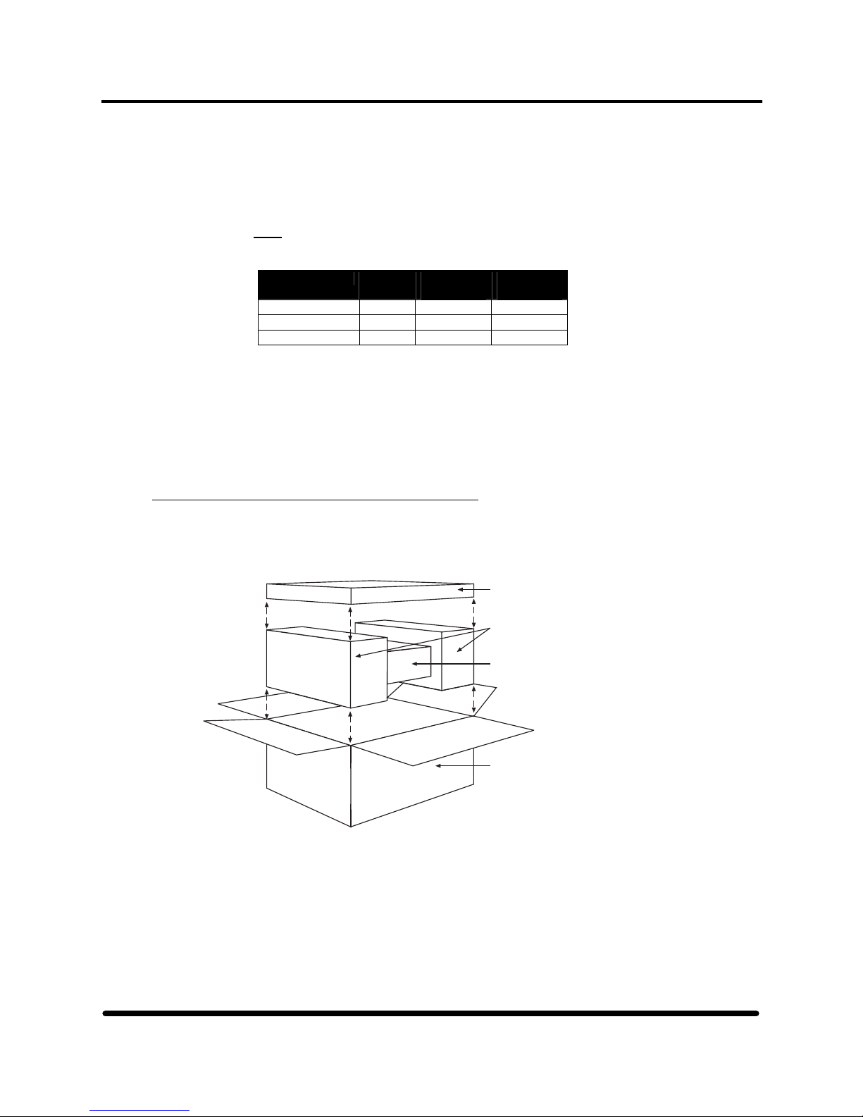
3.2.2 Unpacking the 5242 and 5242-ACL Tape Drives
The 5242 and 5242-ACL tape drives are shipped in individual cartons. Each carton contains the tape
enclosure and a User's Kit. (See Figure 4.) A copper SCSI interface cable, if ordered, is shipped in a
separate box.
5242-ACL
Amperes
User's Kit
Foam
Supports
Tape
Subsystem
Enclosure
Shipping
Container
Figure 4 Unpacking a 5242 or 5242-ACL tape drive
HP StorageWorks DAT 72 (Models 5242 and 5242-ACL) User's Guide 8 HP Part Number 528296-03 July 2005
Page 16

Section 1: General Information
3.2.2.1 The 5242 User's Kit contains:
• One 68-pin high voltage differential terminator
• One 170 meter DAT72 data cartridge
• One cleaning cartridge
• One power cable
• One CD user manual
3.2.2.2 The 5242-ACL User's Kit contains:
• One 68-pin high voltage differential terminator
• One 170 meter DAT72 data cartridge
• One cleaning cartridge
• One 6-tape magazine
• One user manual on CD
3.2.2.3 To unpack the 5242 or 5242-ACL tape drive:
1. Use a utility knife to cut the tape holding the carton's top flaps closed.
2. Open the flaps and remove the User's Kit box.
3. Lift the enclosure and foam supports out of the container. Set on a flat level surface.
4. Carefully remove the foam supports from either end of the tape drive enclosure.
5. Inspect the tape drive for shipping damage.
: Record any damage on the shipping bill. Report any damaged equipment to HP.
Note
Failure to report damaged equipment immediately can result in a loss of claim.
6. Check you have:
• 5242 or 5242-ACL tape drive
• User's Kit containing user manual, terminator, and power cord. If you are using a
5242-ACL, you will also find a 6-tape magazine.
7. Move the 5242 or 5242-ACL tape drive into place. Note the service clearance
information. See Section 1, Chapter 3, Page 6.
8. Install the tape drive and connect it to the NonStop server. See the next section.
3.2.3 Installing the 5242 and 5242-ACL Tape Drive
This subsection describes the steps necessary to install the 5242 or 5242-ACL tape drives.
3.2.3.1 Connecting and Routing the AC Power Cord
An AC power cord connects the power supply in the 5242 and 5242-ACL tape drive to the
external power source. To connect an AC power cord to the 5242 and 5242-ACL tape
drives (assumes a non-computer-room installation):
1. Check that the AC power switch on the tape drive is set to the OFF (0) position. This
prevents power from being accidentally supplied to the tape drive.
2. Plug the AC power cord connector into the AC power receptacle at the rear of the tape
drive. See Figures 5 and 6.
3. Plug the other end of the AC power cord into the external power source. For
information about power requirements, see AC Power Requirements on page 8.
4. Move the 5242 or 5242-ACL tape drive into place. Note the service clearance
information under Service Clearance and Dimensions on page 6.
5. Install the 5242 or 5242-ACL tape drive and connect it to the NonStop server.
HP StorageWorks DAT 72 (Models 5242 and 5242-ACL) User's Guide 9 HP Part Number 528296-03 July 2005
Page 17
Section 1: General Information
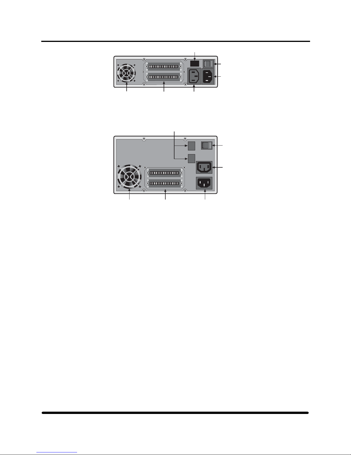
Blank
Fan AC Out
SCSI
Connectors
AC Out
Power
Power
Connector
Connector
l
O
Power
Switch
AC In
Power
Connector
Figure 5 5242 subsystem rear panel
Blank
l
O
Power
Switch
AC Out
Power
Connector
Fan
SCSI
Connectors
AC In
Power
Connector
Figure 6 5242-ACL subsystem rear panel
3.2.3.2 Connecting a SCSI Cable to the Tape Drive FRU
Copper SCSI cables come in lengths ranging from 3 to 25 meters (10 – 82 feet) and do not
require special installation. At the rear of each tape drive FRU, there are two 68-pin SCSI
ports. SCSI cable links. Connect one of these ports to the NonStop S-series server, M8201
Fibre Channel to HVD SCSI router, or S-Series I/O enclosure for use on Integrity NonStop
servers.. A SCSI terminator plugs into the other port. See Figure 9. Connect the SCSI cable
to the SCSI port on the tape drive:
1. Locate the SCSI cable.
2. Align the 68-pin SCSI cable connector, which has thumb screw connectors, with the
uncapped SCSI port on the top as you face the rear of tape drive.
3. Attach the 68-pin SCSI cable connector to the SCSI port and secure the thumb screw
connectors. (See Figure 7.)
4. Ensure a SCSI terminator is firmly installed one of the two SCSI ports.
HP StorageWorks DAT 72 (Models 5242 and 5242-ACL) User's Guide 10 HP Part Number 528296-03 July 2005
Page 18
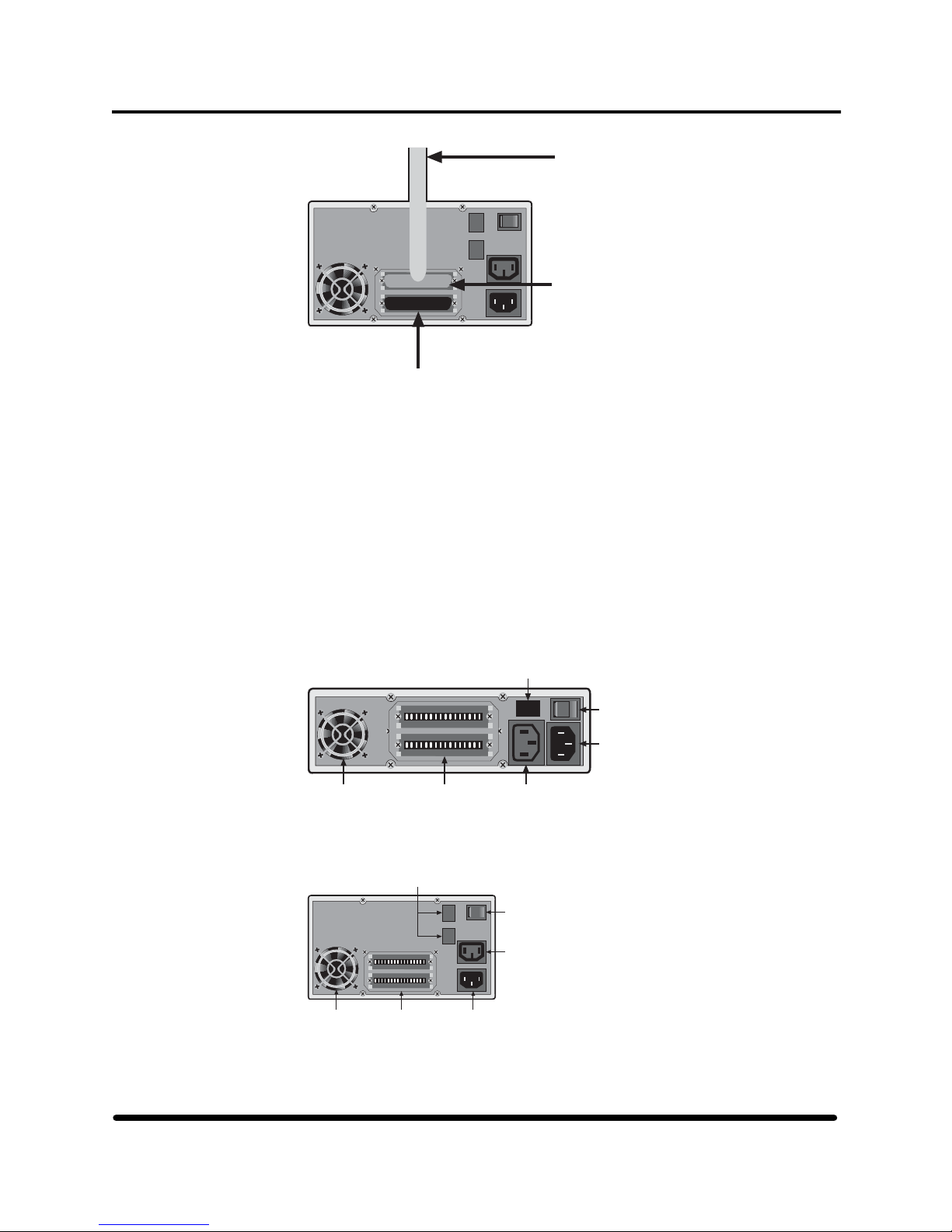
Section 1: General Information
Copper
SCSI Cable
to PMF CRU
l
O
SCSI Port
SCSI
Terminator
on Port
Figure 7 Connecting the SCSI cable to the drive
3.2.3.4 Bringing the Tape Drive Online
After the 5242 or 5242-ACL tape drive has been installed and the cables attached, bring the
tape drives online. For each tape drive:
1. Verify the AC power cord for the tape drive is plugged into an external power source.
2. Check that the 5242-ACL magazine is not in the drive.
3. Apply power to the tape drive by setting the AC power switch to the ON (|) position. To
power off the tape drive, set the AC power switch to the OFF (0) position. See Figures 8
and 9.
Blank
l
O
Power
Switch
AC In
Power
Connector
Fan AC Out
SCSI
Connectors
AC Out
Power
Power
Connector
Connector
Figure 8 AC power switch on the 5242 tape drive
Fan
Blank
SCSI
Connectors
l
AC In
Power
Connector
O
Power
Switch
AC Out
Power
Connector
Figure 9 AC power switch on the 5242-ACL tape drive
HP StorageWorks DAT 72 (Models 5242 and 5242-ACL) User's Guide 11 HP Part Number 528296-03 July 2005
Page 19
Section 1: General Information
4. Observe the progress of the power-on self-test on the front panel of the tape drive. See
5242-ACL Power-Up Sequence or Tape Drive Power-Up Sequence on page 12.
5. After the drive is installed and configured, bring up the path to the system using the
SCF START command:
1>SCF
->START $TAPE1
->EXIT
6. Run SCF commands to ensure the integrity of the modular tape subsystem. For the SCF
commands, see Starting and Testing the Tape Drives page 16.
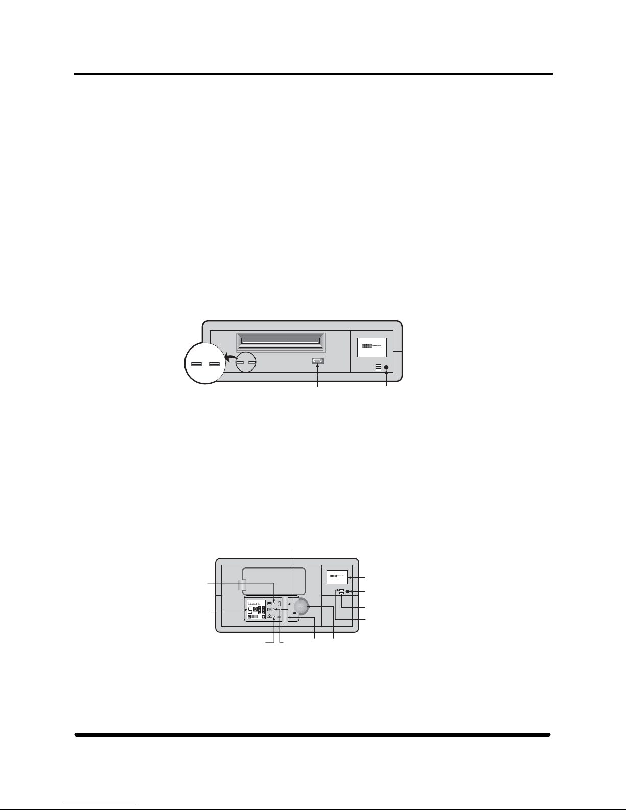
3.2.3.5 5242 Tape Drive Power-Up Sequence
When power is applied to the 5242 tape drive, the tape drive performs a series of self-tests to
verify operation. The two LEDs (green and amber) below the drive access slot both turn on
for one second. The amber light then turns off and the green LED flashes for 6 seconds. Both
LEDs turn off when self-test completes. The LCD displays power-on self test for 2 seconds
and then switches to the revision screen.. The tape drive is ready for operation when the
revision screen appears on the front panel LCD. You can load a cartridge at this point by
inserting the cartridge into the tape drive's access slot. If an error message appears during the
power-up sequence, see Troubleshooting the 5242 and 5242-ACL Tape Drives on page 17.
Write
E F
COMPRESS
Tape Clean/
Attn.
12
12
2.3:1
Detail
A
Eject
Button
Mode
Switch
Figure 10 5242 tape drive LEDs
3.2.3.6 5242-ACL Power-Up Sequence
The AC power switch at the rear of the tape drive powers all internal components. When power
is applied, the 5242-ACL performs a series of self-tests to verify operation of the 5242-ACL
control panel LED, LCD, and the autoloader. The 5242-ACL has two LCD screens: the tape
drive LCD and the autoloader LCD. (See Figure 15.) The tape drive LCD is the main display
and is located on the right side of the front panel when facing the front of the tape drive. This
display operates the same as described for the 5242 tape drive. The autoloader LCD is located
below the drive's magazine access door. Next to this display are three LEDs.
Magazine
Present
LED
Autoloader
LCD
Operator
Attention
Required
LED
Select Button
6
Eject
Tape
Activity
LED
Load
Tape
Button
Write
E F
COMPRESS
2.3:1
Eject
Button
4-Line LCD,
8-Characters per line
Mode
Switch
Programmable
Error-Alert LED
Compression
Indicator LED
Figure 11 5242-ACL front panel identified
HP StorageWorks DAT 72 (Models 5242 and 5242-ACL) User's Guide 12 HP Part Number 528296-03 July 2005
Page 20
Section 1: General Information
The 5242-ACL's power-up sequence includes:
1. The three LEDs blink until the self-test completes (approximately 30 seconds).
2. All segments of the 5242-ACL's autoloader LCD are energized.
3. The SCSI ID of the internal drive electronics displays on the autoloader LCD. This is not
the same ID as seen by the NonStop server.
4. The value of the internal drive configuration switches is shown. It should be FF1.
5. A self-test message displays on the 5242-ACL autoloader LCD.
6. The Insert Mag message appears on 5242-ACL autoloader's LCD indicating that the tape
drive is ready for operation.
If the magazine is inserted (but not loaded) during the power-up sequence, a message
prompts you to close the door. The drive is ready for operation when the Insert Mag
message appears on the autoloader LCD. Load a cartridge by inserting it into the slot until
the loader takes it in automatically. If an error message appears during the power-up
sequence, see Troubleshooting the 5242 and 5242-ACL Tape Drives on page 17.
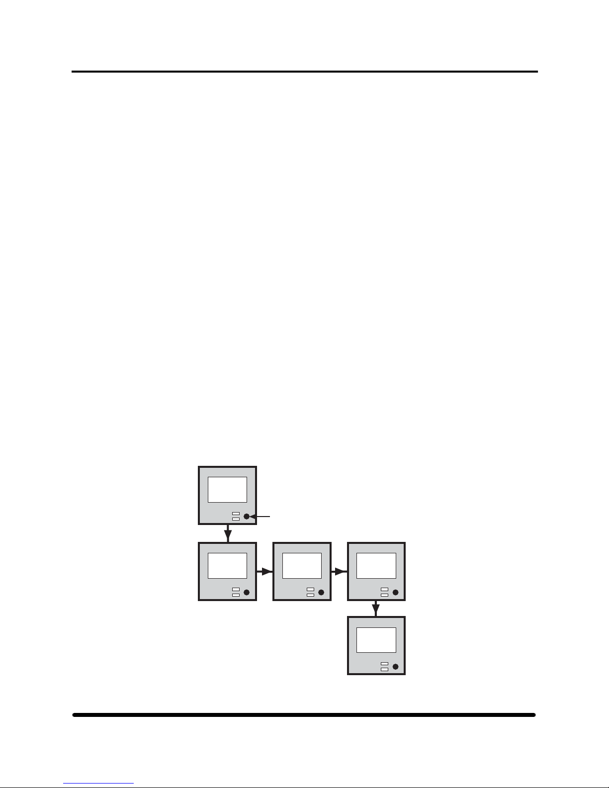
3.2.3.7 Checking and Setting the SCSI ID
The SCSI ID identifies the tape drive to the NonStop server. To display the SCSI ID, use the
mode button and main LCD on the tape drive front panel. Tape drives attached to a NonStop
server use a SCSI ID of 5 (daisy-chained drives use IDs 5 and 4). Tape drives always shipped
with a SCSI ID of 5. Check the SCSI ID during installation, or after tape drive replacement.
The SCSI ID of a tape drive is stored in nonvolatile RAM. You can check or set the SCSI ID
using the mode button and main LCD on the tape drive front panel. Power must be cycled to
the tape drive to check or set the SCSI ID. The procedure is the same for both the 5242 and
5242-ACL. Familiarize yourself with the 5242 and 5242-ACL front-panel controls before
beginning this procedure and review Sections 2 and 3.
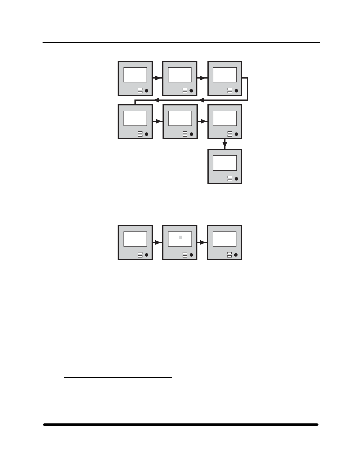
1. Press the mode switch while powering on the 5242 or 5242-ACL tape drive. The following
displays appear on the main LCD and cycle at a two second interval:
*Set-Up*
Release
Button
to Start
Mode
Switch
Enter
Set-Up 1
PRESS to
Select
Enter
Set-Up 2
PRESS to
Select
Enter
Set-Up 3
PRESS to
Select
Exit
Set-Up
PRESS to
Select
Figure 12 5242 and 5242ACL setup menus
HP StorageWorks DAT 72 (Models 5242 and 5242-ACL) User's Guide 13 HP Part Number 528296-03 July 2005
Page 21
Section 1: General Information
2. Push the mode switch when Setup 1 appears. Screens cycle at a 2-second interval.
Enter
Set-Up 1
PRESS to
Select
Tape
Term: On
*NOT sel
ectable*
SCSI ID:
[00]
PRESS to
Alter
Density:
[C0]
PRESS to
Alter
Tape ID:
[00]
*NOT sel
ectable*
Rwr% 0.5
Ecc: 0.5
PRESS to
Alter
Exit
Set-Up 1
PRESS to
Select
Figure 13 Setup 1 configuration menu
3. Select the SCSI ID screen by pressing the mode switch when the SCSI ID screen
appears. This configuration menu item allows you to set the SCSI ID.
SCSI ID:
[00]
PRESS to
Alter
Figure 14 Setting the SCSI ID
4. When the screen reads PRESS to Alter, press the mode switch.
5. The LCD shows the instruction PRESS to Increment. On the second line of the
display, a highlight indicates what digit is alterable. To increment the digit, press the
mode switch.
6. If no mode switch activity occurs for four seconds, the display shows PRESS if Done
to confirm the setting. The displays returns to the Setup 1 configuration menu. Press
the mode switch to exit the setup menus.
7. Check the new SCSI ID:
8. After setting the SCSI ID, cycle power to the drive using the AC power switch on the
rear of the tape drive. Once complete, check the stored SCSI ID is correct. The ID is
shown in the revision display on the main front panel LCD after power-up (ID is
shown in the three right most positions on the last line of the display). Alternately,
repeat the procedure in Checking and Setting the SCSI ID on page 13.
3.2.4 Starting and Testing the Tape Drives
This subsection describes the SCF commands to be used to start and test tape devices.
3.2.4.1 Starting a Tape Device
SCSI ID:
[01]
PRESS to
Incremnt
SCSI ID:
[01]
PRESS if
Done
HP StorageWorks DAT 72 (Models 5242 and 5242-ACL) User's Guide 14 HP Part Number 528296-03 July 2005
Page 22

Section 1: General Information
Use the SCF START TAPE command to start a tape device after the 5242 or 5242-ACL
tape drive has been installed. The START command makes a stopped tape drive accessible
to user processes. When the START command finishes successfully, the tape drive is in the
STARTED state. For more on the START command, see the SCF Reference Manual for
the Storage Subsystem. For example:
->START $TAPE0
3.2.4.2 Testing a Tape Device
Use the SCF STATUS TAPE, DETAIL command to produce a report that shows
information such as processor numbers for the tape process, logical device number of the
tape device, and current state of the tape device. For example:
->STATUS TAPE $TAPE0, DETAIL
STORAGE – Detailed Status TAPE $TAPE0
Tape Process Information:
LDev State SubState Primary Backup DeviceStatus
68 STARTED 0,291 1,273 ONLINE,BOT
Current Settings:
ACL ..............NOT INSTALLED/UNK BufferLevel .......RECORD
CheckSumMode .....NORMAL I/O *Compression ......OFF
Density ..........2.4-4.8 KB/mm Media Type ........Not applicable
Opens ............0 Product ...........5140/5142
RecSize ..........2048 Short Write Mode ..ALLOWED, PADDED
Subtype ..........11 Tape Mode .........STREAM
Volume Switching .EOT
PID PID
Figure 15 Example of a SCF status tape detail command
HP StorageWorks DAT 72 (Models 5242 and 5242-ACL) User's Guide 15 HP Part Number 528296-03 July 2005
Page 23

Section 1: General Information
This report shows $TAPE0 is:
• Using processor 0 as the primary processor
• Using processor 1 as the backup processor
• Logical device 68
• In the STARTED state
• Currently online at BOT
• A DDS-3 (5142) tape drive (5242 would be shown for that model)
For more on the STATUS command, refer to the SCF Reference Manual for the Storage
subsystem
3.2.5 Troubleshooting the 5242 and 5242-ACL Tape Drives
These troubleshooting tables help identify and correct problems that can occur when installing the
5242 or 5242-ACL tape drives. Each table addresses a specific problem, lists symptoms related to
the possible cause of the problem, and lists actions to correct problem. If you need further help
solving an installation problem, contact the HP Global Customer Support Center.
5242 Tape Drive Does Not Function Properly
Symptom Correct Action
Tape drive does not respond
to software commands, or it
functions abnormally.
Note: Refer to page 32 to
identify error
conditions indicated
by drives status LEDs.
• Check that a SCSI cable is
firmly attached to one of
the SCSI ports on the back
of the tape drive.
• Use SCF commands to
isolate the problem in the
tape drive. See SCF
example commands on
page 19.
• Check that the SCSI ID is
set to 5.
• If SCSI bus termination
problems are suspected,
check the terminator on the
rear of the tape drive.
• If you cannot find the
problem, contact the
GCSC.
Table 8 Troubleshooting the 5242 Tape Drive
HP StorageWorks DAT 72 (Models 5242 and 5242-ACL) User's Guide 16 HP Part Number 528296-03 July 2005
Page 24

Section 1: General Information
5242ACL Tape Drive Does Not Function Properly
Symptom Correct Action
5242-ACL does not respond to
commands, or it functions
abnormally.
Note: Refer to page 32 for
error messages
displayed by the ACL.
• Check that one of the SCSI
cables listed on page 1
connects the tape drive to
the NonStop server.
• Check that the SCSI ID is
set to 5.
• Check that a SCSI
terminator is firmly
installed on the unused
SCSI port on the back of
the tape drive Then turn
power off and on again.
• If the error message or
check code persists, contact
the GCSC.
Table 9 Troubleshooting the 5242ACL Tape Drive
3.3 Configuring the 5242 and 5242-ACL for NonStop servers
This subsection describes how to configure the 5242 and 5242-ACL tape drive to a processor multifunction
(PMF) or IOMF:
• The group, module and slot hierarchy
• Identifying FRUs
• Completing the PMF or IOMF Configuration Form
• Configuring the 5242 and 5242-ACL tape drive online using SCF
Integrity NonStop servers are also covered in this section. They are configured in a similar manner except for
the addition of some extra syntax specific to the Integrity server.
3.3.1 The Group, Module and Slot Hierarchy
Components in a NonStop S-series server are organized according to a group, module, and slot
hierarchy:
3.3.1.1 Group
A group consists of all objects accessible to a pair of service processors (SPs) in a system
enclosure. A NonStop S-series group contains one enclosure with a single module.
3.3.1.2 Module
A module is a set of components sharing a common hardware interconnection, such as a
backplane. A module is a subset of a group, and it is usually contained in a system
enclosure. A module contains one or more slots. In a NonStop S-series server, there is
one module in a group.
HP StorageWorks DAT 72 (Models 5242 and 5242-ACL) User's Guide 17 HP Part Number 528296-03 July 2005
Page 25

Section 1: General Information
3.3.1.3 Slot
A slot is a labeled physical space in an enclosure into which a FRU is installed. FRUs are
replaced by HP certified service providers.
3.3.2 Identifying FRUs
FRUs in NonStop S-series servers are identified by their physical location. To locate an FRU, you
need to know:
3.3.2.1 Group Number
The group number identifies all objects connected through the service processors (SPs)
located on the processor multifunction (PMF). For NonStop S-series servers, this includes
everything in a system enclosure.
3.3.2.2 Module Number
For Nonstop S-series servers, there is only one module in a group, so the module number is
always 1.
3.3.2.3 Slot Number
The slot number identifies a position within a module. The slot number is indicated by a
label beneath the slot.
Group and slot labels help you locate I/O controllers that need service. Some software might show
the location using abbreviations for group, module, and slot. For example, the Subsystem Control
Facility (SCF) storage subsystem might display the location of a PMF or IOMF as:
PMF.GRP-1.SLOT-50
For more information on system organization, group numbering, or labeling for a NonStop S-series
server, refer to the Nonstop S-Series Planning and Configuration Guide.
3.3.3 Completing the PMF Configuration Form
If you plan to connect a tape drive to a PMF or IOMF, document the configuration using a
Configuration Form. This form documents configurable entities associated with the connector. It
also provides information about the tape drive to be connected.
: Ensure the IOMF or PMF is terminated on the NonStop S-series server.
Note
3.3.3.1 Enter the product number of the tape drive in the Product Number field. Allowable product
numbers are 5242 and 5242ACL.
HP StorageWorks DAT 72 (Models 5242 and 5242-ACL) User's Guide 18 HP Part Number 528296-03 July 2005
Page 26

Section 1: General Information
3.3.3.2 Enter the Subsystem Control Facility (SCF) name of the tape drive in the SCF name field.
3.3.3.3 Enter the product number of the SCSI cable you plan to use with this tape drive in the SCSI
cable field. You must use one of the SCSI cables listed on page 1.
3.3.4 Configuring the 5242 and 5242-ACL Tape Drive Online Using SCF
Use the Subsystem Control Facility (SCF) to configure tape drives for NonStop servers. SCF allows
you to add, change the attributes of, and delete a tape drive. You can run SCF from any terminal on
the system after you are logged on. Using SCF, you can:
• Obtain configuration information about a tape drive
• Restore access to a tape drive
• Stop access to a tape drive if there is no activity
• List tape drive status
• Switch the primary processor for a tape drive
: Use the product code 5242 when configuring the 5242 tape drive or 5242-ACL when
Note
configuring a 5242-ACL tape drive.
For information about how to use SCF to configure, control, and inquire about all supported tape
drives for Nonstop S-series servers, see the SCF Reference Manual for G-Series RVUs.
Example 1: Defining and Adding a Tape Drive
Use the SCF ADD TAPE command to define and add a 5242 or 5242-ACL tape drive to the
NonStop server configuration.
Before using the ADD TAPE command, check that the tape drive is installed properly. For
installation instructions, refer to page 5. Verify the group enclosure, module, and slot to which the
tape drive it is connected.
The first example below adds a 5242 tape drive, $TAPE0. to a NonStop S-series system. The second
example adds a 5242 tape drive, $TAPE0, to an Integrity NonStop server system configuration:
-
->&PRIMARYCPU 0, BACKUPCPU 1, PRODUCT 5242
>ADD TAPE $TAPE0, SENDTO STORAGE, LOCATION (2, 1, 55),&
->ADD TAPE $TAPE1, SENDTO STORAGE, LOCATION (110, 3, 2),LUN0, SAC2, PORTNAME WWN OF DEVICE TO BE
->&PRIMARYCPU 2, BACKUPCPU 3, PRODUCT 5242
CONNECTED
In this example:
• The LOCATION attribute specifies the location (group, module, slot) of the PMF or IOMF
adapter to which the tape drive is attached.
• The PRIMARYCPU attribute specifies the processor in which the primary tape process should
execute.
• The BACKUPCPU attribute specifies the processor in which the tape process starts its backup
process.
• The PRODUCT attribute specifies the product number that identifies the model of the tape
drive.
HP StorageWorks DAT 72 (Models 5242 and 5242-ACL) User's Guide 19 HP Part Number 528296-03 July 2005
Page 27

Section 1: General Information
For the Integrity NonStop server:
The LUN attribute specifies the logical unit address of the target. LUNs 0 to 15 are valid.
The SAC attribute specifies the deck on the adapter.
The PORTNAME attribute specifies the worldwide name address of the tape target (WWN OF
THE DEVICE TO BE CONNECTED).
For NonStop servers, issue the SCF INFO TAPE command after the ADD TAPE command is
finished to verify that the tape drive has been properly configured. For example:
->INFO TAPE $TAPE0, DETAIL
STORAGE – Detailed Info TAPE configuration $TAPE0
Adapter Name .............................$ZZSTO.PMF.GRP-2.MOD-1.SLOT-55
*Adapter Location (Group,Module,Slot) .....(2,1,55)
BackupCpu ................................1
*Compression ..............................OFF
*Density ..................................2.4-4.8 KB/mm
*HighPin ..................................ON
*MaxOpens .................................4
PrimaryCpu ...............................0
Product ..................................5140/5142
*Program ..................................$SYSTEM.SYSTEM.OTPROCP
*RecSize ..................................2048
*StartState ...............................STARTED
Figure 16 Example of a SCF info tape command (5142 DDS-3 Drive)
For NonStop servers, the ADD TAPE command adds a 5242 tape drive connected to the PMF CRU
in group 02, module 1 and slot 50 to the system configuration using the name $TAPE1:
-
->&PRIMARYCPU 2, BACKUPCPU 3, PRODUCT 5242
>ADD TAPE $TAPE1, SENDTO STORAGE, LOCATION (2, 1, 50)),&
The syntax is slightly different for Integrity NonStop servers:
-
->&PRIMARYCPU 2, BACKUPCPU 3, PRODUCT 5242
>ADD TAPE $TAPE1, SENDTO STORAGE, LOCATION (110, 3, 2),LUN0, SAC2, PORTNAME wwn of device to be connected
For more information on the ADD and INFO commands, see the SCF Reference Manual for the
Storage Subsystem.
Example 2: Changing the Values of Tape Drive Attributes
Use the SCF ALTER TAPE command to change the attribute values for a tape drive attached to
your system. The ALTER command changes only the attributes that are specified in the command.
Other attributes remain as they were before you issued the command.
This example of the ALTER command changes the value of the compression attribute for the 5242
or 5242-ACL tape drive $TAPE0 to OFF and then issues the SCF INFO command to check the
change has taken place:
>ALTER TAPE $TAPE0, COMPRESSION OFF
>INFO TAPE $TAPE0
STORAGE – Info TAPE configuration $TAPE0
SubType Density *MaxOpens *RecSize *TapeMode *Compression Adapter
11 38000 BPI 4 2048 STREAM OFF 1,1,55
Location
Figure 17 Example of the alter command
HP StorageWorks DAT 72 (Models 5242 and 5242-ACL) User's Guide 20 HP Part Number 528296-03 July 2005
Page 28

Section 1: General Information
This example changes tape drive $TAPE1 so that its tape process runs only at a low PIN and then
checks that the change has taken place:
>ALTER TAPE $TAPE1, HIGHPIN OFF
>INFO TAPE $TAPE1, DETAIL
STORAGE – Detailed Info TAPE configuration $TAPE1
Adapter Name .............................$ZZSTO.PMF.GRP-2.MOD-1.SLOT-55
*Adapter Location (Group,Module,Slot) .....(2,1,55)
BackupCpu ................................3
*Compression ..............................OFF
*Density ..................................2.4-4.8 KB/mm
*HighPin ..................................OFF
*MaxOpens .................................4
PrimaryCpu ...............................2
Product ..................................5140/5142
*Program ..................................$SYSTEM.SYSTEM.OTPROCP
*RecSize ..................................2048
*StartState ...............................STARTED
Figure 18 Example of a tape drive running at a low PIN
This example specifies that a maximum of 32 concurrent file opens are allowed for the tape drive
$TAPE1:
>ALTER TAPE $TAPE1, NUMOPENERS 32
For more information on the ALTER and INFO commands, see the SCF Reference Manual for the
Storage Subsystem.
Example 3: Deleting a Tape Drive From the System
Use the SCF DELETE TAPE command to delete a tape drive form the system configuration
database.
Before issuing the DELETE command, use the SCF STATUS command to verify that the tape
drive is in the STOPPED state:
>STATUS TAPE $TAPE0
STORAGE – Status TAPE $TAPE0
LDev State SubState Primary Backup DeviceStatus
20 STOPPED 0,30 1,30
PID PID
Figure 19 SCF delete tape command
If the STATUS command shows that the tape drive is not in the STOPPED state, use the SCF STOP
command to place the tape drive in the STOPPED state. For example:
>STOP TAPE $TAPE0
This example removes tape drive $TAPE0 from the system configuration:
>DELETE TAPE $TAPE0
Use the INFO command to verify that the tape drive has been removed from the system:
>INFO $TAPE*
HP StorageWorks DAT 72 (Models 5242 and 5242-ACL) User's Guide 21 HP Part Number 528296-03 July 2005
Page 29

Section 1: General Information
4.1 Preventive Maintenance
To maintain optimum performance and to prevent READ/WRITE errors, the tape heads of the 5242 and
5242-ACL tape drive must be cleaned on a regular basis. Use the recommended cleaning schedule per
cartridge type as specified in Table 10. Cleaning procedures for each tape drive model follow.
Warning
Use only reliable HP approved cleaning cartridges.
4.2 5242 Tape Path Cleaning
The Clean/Attention LED is located on the front panel of the tape drive. When it flashes amber, the tape
heads are dirty.
Tape Clean/
Attn.
12
12
Chapter Four
Write
E F
COMPRESS
2.3:1
Detail
A
Eject
Button
Mode
Switch
Figure 20 5242 clean/attention LEDs
Warning
The tape heads must be cleaned regularly. Follow the recommended cleaning schedule.
Recommended Cleaning Schedules for
125m DDS-3 and DAT72 Tape Cartridges
Number of
1 2 3 4 or more
DDS cartridges
used each day
Recommended
8 weeks 4 weeks 3 weeks weekly
Cleaning
Frequency
Table 10 5242 cleaning schedule using DDS-3 or DAT72 cartridges
4.2.1 Using the Cleaning Cartridge
: To prevent contamination of the tape drive and damage to the heads do not use the
Note
cleaning cartridge for more than the manufacturer's specified number of cleaning cycles.
Do not attempt to rewind the material in the cleaning cartridge and reuse it.
4.2.1.1 Insert the cleaning cartridge into the drive. The tape drive loads the cleaning cartridge and
cleans the heads. After about 30 seconds, the tape drive ejects the cleaning cartridge.
HP StorageWorks DAT 72 (Models 5242 and 5242-ACL) User's Guide 22 HP Part Number 528296-03 July 2005
Page 30

Section 1: General Information
: If the cleaning cartridge ejects after 14 seconds. The cartridge has reached the end
Note
of its useful life, and no cleaning has occurred. If the cleaning needed LED is still
illuminated, discard the cartridge and repeat the cleaning operation with a new
tape.
4.2.1.2 Remove the cleaning cartridge from the drive. Write the date on the label of the cleaning
cartridge so that you have a record of usage. Do not use the cleaning cartridge more times
than specified by the manufacturer.
4.3 5242-ACL Tape Path Cleaning
Clean the heads regularly. Do not use the cleaning cartridge for more than the manufacturer's specified
number of cleaning cycles. Always and immediately clean the heads when a Clean Me message appears on
the autoloader's LCD and when the Operator Attention LED flashes amber.
Magazine
Present
LED
Autoloader
LCD
Select Button
6
Eject
Write
E F
COMPRESS
2.3:1
4-Line LCD,
8-Characters per line
Mode
Switch
Programmable
Error-Alert LED
Compression
Indicator LED
Load
Operator
Attention
Required
LED
Tape
Activity
LED
Button
Tape
Eject
Button
Figure 21 5242-ACL front panel
Recommended Cleaning Schedule for
125m DDS-3 and 170m DAT72 Tape Cartridges
Number of
1 2 3 4 or more
DDS cartridges
used each day
Recommended
8 weeks 4 weeks 3 weeks weekly
Cleaning
Frequency
Table 11 5242-ACL cleaning schedule using DDS-3 or DAT72 cartridges
4.3.1 Cleaning the Heads:
4.3.1.1 Place the cleaning cartridge into the first magazine slot. Insert the magazine into the
autoloader. The tape loads automatically into the drive.
4.3.1.2 At the end of the cleaning cycle, the drive automatically ejects the cartridge. The changer
mechanism places it in the magazine.
HP StorageWorks DAT 72 (Models 5242 and 5242-ACL) User's Guide 23 HP Part Number 528296-03 July 2005
Page 31

Section 1: General Information
4.3.1.3 Eject the magazine and write the date on the label of the cleaning cartridge so that yopu
have a record of usage. Do not use the cleaning cartridge more times
manufacturer.
: Leaving the cleaning cartridge in the magazine reduces the amount of data you can back
Note
up to the magazine however, leaving the cleaning cartridge in the magazine ensures that
the tape drive is cleaned prior to running a long job.
4.3.2 Cleaning Cartridge Life
If the Clean Me message still appears on the autoloader's LCD after you use the cleaning cartridge, the
cleaning cartridge might have expired. If so, discard the cartridge and repeat the operation with a new
cleaning cartridge.
4.4 Cleaning the Exterior
4.4.1 Enclosure:
Use a soft, damp, lint-free cloth to clean the enclosure.
Caution
4.4.2 LCD:
Put household glass cleaner on a soft cloth and wipe the screen.
Caution
: Do not use aerosol sprays, solvents, or abrasives that might damage the finish.
: Do not spray the cleaner directly on the LCD because the liquid might drip into
4.5 Operating Environment
The 5242 and 5242-ACL tape drives operate in any clean, indoor location. Do not store or operate the tape
drive outside of the environmental ranges listed in Chapter 6.
4.5.1 Avoid placing the tape drive in direct sunlight, rain or other sources of moisture
4.5.2 Keep all the tape drive ventilation openings unobstructed.
Avoid getting moisture in any openings.
the tape drive.
than specified by the
HP StorageWorks DAT 72 (Models 5242 and 5242-ACL) User's Guide 24 HP Part Number 528296-03 July 2005
Page 32

Section 1: General Information
Chapter Five
5.1 Technical Support
Customers can contact HP Global Customer Support Center (GCSC). When calling the GCSC, have this
information available:
• Serial number of the equipment
• The initial LCD display showing the firmware revision
• The Performance LCD display when the error occurs
• A detailed description of the problem you are having with the equipment
• Your contact information
To order replacement 5242 and 5242-ACL tape drives:
Description Part Number
5242 Spare tape drive FRU 528081-001
5242-ACL Spare tape drive FRU 528086-001
HP StorageWorks DAT 72 (Models 5242 and 5242-ACL) User's Guide 25 HP Part Number 528296-03 July 2005
Page 33

Section 1: General Information
6.1 Cabling Limitations
Maximum total allowable cable length for a differential SCSI interface is 82 feet (25 meters). This distance
must be measured from the controller to the last device on the bus. Cables must be 110 ohm twisted pair. If
you are using a cable of unknown composition, replace it with the one provided by HP. When ordering,
reference one of these part numbers:
519-001W 424360-001 1 meter (3 foot) SCSI Cable 68-pin to 68-pin
519-003W 424361-001 3 meter (10 foot) SCSI Cable 68-pin to 68-pin
519-015W 424362-001 15 meter (50 foot) SCSI Cable 68-pin to 68-pin
519-020W 424917-001 20 meter (67 foot) SCSI Cable 68-pin to 68-pin
519-023W 424363-001 23 meter (77 foot) SCSI Cable 68-pin to 68-pin
6.2 Differential Devices
The 5242 and 5242-ACL tape drives support a high voltage differential SCSI-3 interface.
6.3 Cooling Fan and System
The cooling system provides excellent heat dissipation at critical locations, such as read/write heads, where
excess heat results in higher data failure. A unique airflow design directs cool air over these critical locations
within the chassis.
6.4 Specifications
This section provides technical specifications for the tape drives.
6.4.1 Electrical Specifications
6.4.1.1 External AC power:
6.4.1.2 AC power outlet (to be used for stacking units only)
6.4.1.2 Internal DC power:
6.4.2 Display Unit
• 32 characters in 4 lines of 8 characters each
• Supertwist LCD technology
• Extra-wide viewing angle
• Full LED back lighting
• V115/230 1.0/0.5A 50/60 Hz
• V115/ 230 7.0/3.5A 50/60 Hz
• 5242
• 5242-ACL:
: +5, +12 volts 25 watts
Chapter Six
+5, +12 volts 65 watts
HP StorageWorks DAT 72 (Models 5242 and 5242-ACL) User's Guide 26 HP Part Number 528296-03 July 2005
Page 34

Section 1: General Information
6.4.3 SCSI Cables
75 feet (23m) maximum
6.4.4 Agency Approvals
See Section 6 page 70 for Agency certification statements.
6.4.5 Interfaces
6.6.5.1 SCSI-3 high voltage differential
6.6.5.3 Connectors 68-pin high density
6.4.6 Environmental Specifications
6.4.6.1 Operating temperature:
5ºC to 40ºC with tape loaded
6.4.6.2 Nonoperating temperature:
-40ºC to 45ºC
6.4.6.3 Operating humidity:
20% to 80% relative humidity with tape loaded
6.4.6.4 Nonoperating humidity:
5% to 95% relative humidity
6.4.7 Physical Specifications
6.4.7.1 5242 dimensions:
6.4.7.2 5242-ACL dimensions:
6.4.7.3 Weight:
• L11.5" x W8.3" x H2.5"
• L292mm x W211mm x H64mm
• L11.5" x W8.3" x H4.2"
• L292mm x W211mm x H107mm
• 5242: 7.0 lbs. (3.18 kg)
• 5242-ACL: 10.0 lbs. (4.54 kg)
HP StorageWorks DAT 72 (Models 5242 and 5242-ACL) User's Guide 27 HP Part Number 528296-03 July 2005
Page 35

Section 2: HP 5242 Tape Drive
1.1 Introduction
The 5242 tape drive is a 4mm, single-tape backup device combining an easy-to-read display with high
performance electronics for reliable performance. The front panel LCD provides a clear and comprehensive
status report of the tape drive's activities.
Section 2
5242 Tape Drive
Chapter One
Write
E F
COMPRESS
2.3:1
Figure 22 5242 tape drive
1.1.1 The 5242 tape drive includes:
• Tape drive
• LCD status display and control panel
• Differential SCSI interface
• Terminator
• Power supply and fan (integrated into the enclosure)
• Power cord
• User manual
1.2 5242 Features
• Support for both DDS-3 125m and DAT72 170m tape cartridges
• Firmware upgradeable by code tape
• Subsystem firmware upgradeable by code tape
• Sustained streaming transfer rate of 3 MB/s and up to 2:1 data compression
• Three levels of error correction code (ECC)
• Large 8-megabyte drive data buffer to maintain host transfer rate
• Self-test diagnostics
HP StorageWorks DAT 72 (Models 5242 and 5242-ACL) User's Guide 28 HP Part Number 528296-03 July 2005
Page 36

Section 2: HP 5242 Tape Drive
Chapter Two
2.1 Loading and Unloading a Cartridge
Warning
2.1.1 Loading a Cartridge
Ensure the tape drive power is on and the tape drive is ready before loading a cartridge.
Do not attempt to insert a cartridge backwards or upside down.
2.1.1.1 Power on the tape drive. The power switch is on the rear panel.
Note: Only use DAT72 or DDS-3 cartridges. Do not use DDS-2, DDS-1, or tapes labeled DAT.
2.1.1.2 Insert a cartridge into the slot on the front panel. The drive threads the tape, initiates a
load sequence, and goes on-line.
2.1.1.3 During the load sequence:
1. Tape LED (number 1 in Figure 28) slowly flashes green while the tape is being
loaded.
2. The Tape LED becomes a steady green to indicate the tape is loaded.
3. If an excessive number of errors are detected, the Clean/Attention LED (number 2 in
Figure 23) flashes amber.
Write
E F
COMPRESS
Tape Clean/
Attn.
12
Detail
A
12
Eject
Button
2.3:1
Mode
Switch
Figure 23 Front panel LEDs and tape eject button
2.1.2 Unloading a Cartridge
2.1.2.1 The cartridge ejects from the tape drive either when you press the Eject Button or in
response to a SCSI LOAD/UNLOAD command with the LOAD bit set to 0.
2.1.2.2 The drive rewinds, unloads, and ejects the cartridge unless the drive is not in an idle state
or a contingent operation (which is locking the cartridge) with the NonStop server active.
2.1.2.3 The Tape LED slowly flashes green while the tape unloads. See Figure 27 on page 32.
HP StorageWorks DAT 72 (Models 5242 and 5242-ACL) User's Guide 29 HP Part Number 528296-03 July 2005
Page 37

Section 2: HP 5242 Tape Drive
3.1 Controls and Indicators
This chapter discusses the 5242 controls and indicators by function, location, and type. Figure 24 provides
views of the tape drive front panel and lists controls and indicators. Figure 25 shows the rear panel of the
tape drive and identifies all connectors and switches.
Chapter Three
Tape
Drive
LEDs
Eject
Button
Figure 24 5242 front panel
Fan AC Out
SCSI
Connectors
Figure 25 5242 rear panel
3.2 Understanding the LEDs
The 5242 tape drive has two LEDs that communicate drive status. (See Figure 26. The LEDs can help
determine operating states.
Write
E F
COMPRESS
2.3:1
Compression
Indicator LED
Blank
AC Out
Power
Power
Connector
Connector
4-Line LCD,
8-Characters
per line
Mode
Switch
Programmable
Error-Alert LED
l
O
Power
Switch
AC In
Power
Connector
Tape Clean/
Attn.
12
Detail
A
12
Figure 26 5242 communication LEDs
HP StorageWorks DAT 72 (Models 5242 and 5242-ACL) User's Guide 30 HP Part Number 528296-03 July 2005
Eject
Button
Write
E F
COMPRESS
2.3:1
Mode
Switch
Page 38

Section 2: HP 5242 Tape Drive
3.2.1 The Tape LED (number 1 in Figure 26) uses green to show tape activity:
Slow flashing green while the tape loads or unloads
Steady green when the tape is loaded
Fast flashing green during read or write operations
3.2.2 The
3.2.3 Additional LED patterns
Clean/Attention LED (number 2 in Figure 31) uses amber to show:
Slow flashing amber indicates that the heads need to be cleaned, or the cartridge is
wearing out.
Steady amber indicates a hard fault. The tape drive should be replaced. Call the Global
Customer Support Center.
Key
Activity – load
or unload
Activity – read
or write
Cartridge loaded
Any
Any
Cleaning Needed
signal
Fault
Power-on (starts with
two steady lights
Figure 12 Additional 5242 LED patterns
Off
Green
Amber
Flash Green
(1/2s on, 1/2s off)
Flash Amber
(1/2s on, 1/2s off)
Fast Flash Green
(1/4s on, 1/4s off)
HP StorageWorks DAT 72 (Models 5242 and 5242-ACL) User's Guide 31 HP Part Number 528296-03 July 2005
Page 39

Section 2: HP 5242 Tape Drive
Chapter Four
4.1 Upgrading Firmware From Tape
The 5242 tape drive allows you to upgrade firmware by inserting a firmware upgrade cartridge. The
process takes approximately 3 minutes to complete.
Caution
1. If the firmware upgrade is incompatible with your hardware, no upgrade takes
4.1.1 Upgrading the Firmware
4.1.1.1 Check that the tape drive is not engaged in any SCSI activity. The tape LED is off and the
4.1.1.2 Insert the firmware upgrade tape cartridge into the drive.
4.1.1.3 The upgrade process automatically takes place. During the actual erasure and reprogramming of
4.1.1.4 After about 3 minutes, when the upgrade is complete, the firmware cartridge ejects. Remove it, and
: Do not disconnect power at any time during the upgrade process, particularly when the
front panel lights are flashing, or it may result in the drive having corrupt firmware or no
firmware at all. The drive will then have to be returned to the factory.
place. The tape is ejected after 1 minute instead of the usual 3 minutes.
2. The upgrade tape must not be write-protected.
3. The upgrade tape can only be used a certain number of times. After that, a tape
drive reformats it for normal data use. However, it is not advisable to use it for
data.
4. You cannot convert a firmware upgrade tape for normal use.
NonStop server is not going to be accessing the drive.
the firmware, it is critically important that you do not power down the tape drive. The front panel
LEDs flash rapidly during this critical time.
replace it in its box.
HP StorageWorks DAT 72 (Models 5242 and 5242-ACL) User's Guide 32 HP Part Number 528296-03 July 2005
Page 40

Section 3: HP 5242-ACL Tape Drive
Section 3
5242ACL Tape Drive Subsystem
Chapter One
1.1 Introduction
The 5242-ACL is a 4mm tape backup device. The 5242-ACL offers high-capacity, on-line tape storage,
outstanding performance, and trouble-free operations. It combines a changer mechanism, a DAT 72 tape
drive, data compression, and a SCSI interface. The LCD on the front panel of the 5242-ACL provides a clear
and comprehensive status report of the tape drives activities.
The 5242-ACL houses up to six DAT 72 cartridges In a removable magazine and enables backup of up to
432GB of data, assuming a 2:1 compression ratio. The 5242-ACL supports sequential access mode with
minimum interruption time between cartridges.
1.1.1 The 5242-ACL tape drive includes:
• Tape drive with 6-cartridge magazine
• LCD status display and control panel
• Differential SCSI interface
• Terminator
• Power supply and fan (integrated into the enclosure)
• Power cord
• User manual
Write
E F
COMPRESS
2.3:1
6
Eject
Figure 28 5242-ACL tape drive
1.2 5242-ACL Features
• Cartridge magazine carrying up to six DAT72 cartridges–typical magazine capacity of 216-432
gigabytes using 170m cartridges
• Support for DDS-3 125m tape cartridges
• Tape drive firmware upgradeable by code tape
• Subsystem firmware upgradeable by code tape
• Tape drive streaming transfer rate of 3 MB/s and up to 2:1 data compression
• Three levels of error correction code (ECC)
HP StorageWorks DAT 72 (Models 5242 and 5242-ACL) User's Guide 33 HP Part Number 528296-03 July 2005
Page 41
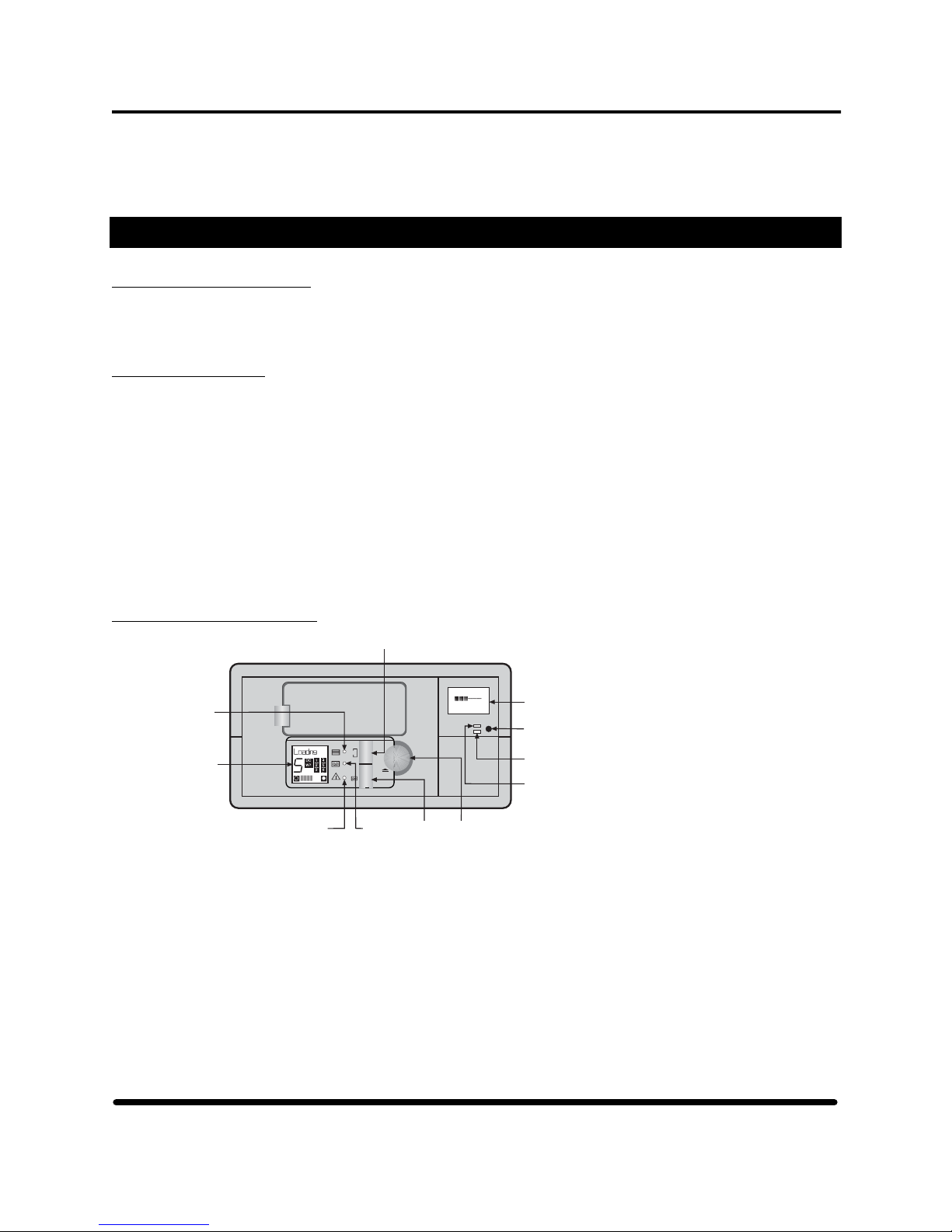
Section 3: HP 5242-ACL Tape Drive
• Large 8-megabyte data buffer to maintain host transfer rate
• Self test diagnostics
Chapter Two
2.1 Mode of Operation
When a cartridge ejects from the 5242-ACL drive following a host UNLOAD command, the autoloader
automatically loads the next available cartridge in the magazine into the drive.
2.2 Terminology
Unloaded A cartridge unloads when it moves from the drive and is placed in the magazine. In this
state, the drive is off-line, and the host cannot perform any operation that would cause tape
motion (write, read, space commands). The NonStop server can issue the LOAD command
to put the tape drive on-line. Additionally, the NonStop server can execute any diagnostic
command that does not access the tape.
Semi-Loaded A cartridge semi-loads when the cartridge is in the tape drive mechanism, but the tape is
not threaded around the head. The tape drive is off-line in this state.
Loaded The tape loads at the end of the load sequence. Then the tape drive is on-line and can
execute all commands, including those that set configurations or run diagnostic tests.
2.3 Front Panel Buttons
Select Button
Write
Magazine
Present
LED
Autoloader
LCD
Operator
Attention
Required
LED
6
Tape
Activity
LED
E F
COMPRESS
2.3:1
Eject
Load
Eject
Tape
Button
Button
4-Line LCD,
8-Characters per line
Mode
Switch
Programmable
Error-Alert LED
Compression
Indicator LED
Figure 29 5242-ACL front panel
HP StorageWorks DAT 72 (Models 5242 and 5242-ACL) User's Guide 34 HP Part Number 528296-03 July 2005
Page 42

Section 3: HP 5242-ACL Tape Drive
2.4 Loading and Unloading the Magazine and Cartridges
Caution
Use only cartridges labeled DAT72 or DDS-3. Do not use DDS-2 or DDS-1 cartridges or any
2.4.1 With the area opposite the side label pointing toward the center of the magazine, place the
: Check that the magazine label adheres firmly to the label area on the magazine. (See Figure
30). If the label is placed anywhere other than in the label area, the magazine might jam in the
mechanism. Ensure that the corners of cartridge and magazine labels stick firmly to the
surface and do not curl at their edges. Remove any old labels from the label area before
placing a new label. Never use non-standard labels, and never stick anything to the cartridge
in any other place than in the label area.
cartridge generically labeled DAT. They will not work.
required number of cartridges into the magazine. (see Figure 30.)
Do Not
fix labels here.
Label
Area
Figure 30 Loading cartridges in a magazine
2.4.2 Loading the Magazine Into the Autoloader
2.4.2.1 With the large arrow on the top of the magazine pointing toward the autoloader, insert the
magazine into the slot in the front of the autoloader. (See Figure 31.)
Figure 31 Inserting a magazine
2.4.2.2 Apply steady pressure until the mechanism takes the magazine and pulls it into the
autoloader. The autoloader then checks which magazine slots contain cartridges.
2.4.2.3 When the magazine check is complete, the tape drive loads the first available cartridge.
2.4.2.4 The tape drive now performs a load sequence:
HP StorageWorks DAT 72 (Models 5242 and 5242-ACL) User's Guide 35 HP Part Number 528296-03 July 2005
Page 43

Section 3: HP 5242-ACL Tape Drive
1. The tape drive mechanism threads the tape and checks the tape's format (DAT72,
DDS-3, blank, cleaning). If the tape is blank, the tape drive leaves the tape at BOM
and waits for the next command.
2. Write and read tests are performed. If the error rate is high, the Operator Attention
LED lights and an error message appears on the LCD. The tape drive then reads the
tape log.
3. The drive rewinds and goes on-line, awaiting a command from the NonStop server.
The load procedure takes a maximum of 25 seconds from the time the cartridge loads to the time
the tape drive is ready to start acting on the next command from the NonStop server.
2.4.3 Once online, the tape drive sends a CHECK CONDITION on receipt of the next SCSI command
from the NonStop server.
2.5 Ejecting the Magazine and Cartridges
2.5.1 A cartridge ejects from the 5242-ACL's autoloader when you press the Eject Button.
2.51.1 The tape rewinds to BOP.
Note: If the tape is write-enabled, the copy of the tape log held in RAM writes back to tape.
2.5.1.2 The tape rewinds to BOM and unthreads.
2.5.1.3 The changer places the cartridge in the magazine.
2.5.1.4 The magazine ejects.
2.5.2 If the NonStop server sends a SCSI LOAD or UNLOAD command with the LOAD bit set as 0,
the same procedure is followed but the magazine is not ejected at the end.
Note: If the NonStop server has previously sent a PREVENT MEDIA REMOVAL command,
the unloading action is different in two ways:
1 The Eject Button is disabled and has no effect. It does not initiate an unload
sequence.
2 An UNLOAD command puts the tape drive into a semi loaded state. The drive is
offline and unthreads the tape, but does not eject it.
The effects of PREVENT MEDIA REMOVAL continue until an ALLOW MEDIA
REMOVAL command is received or the drive is reset.
2.6 Forcing a Tape to Eject
Caution
If you press the Eject Button when the drive is busy, it may be a long time before the
: You can lose data if you force eject a tape. Also, the tape may end up invalidly formatted,
because EOD may not have been written. Force an eject only as a last resort to recover a
cartridge. Never use it as a quick way of ejecting the cartridge
drive responds to the request, because it will first finish the task it is performing. This
ensures that the task terminates in a controlled manner, and no data is lost.
HP StorageWorks DAT 72 (Models 5242 and 5242-ACL) User's Guide 36 HP Part Number 528296-03 July 2005
Page 44
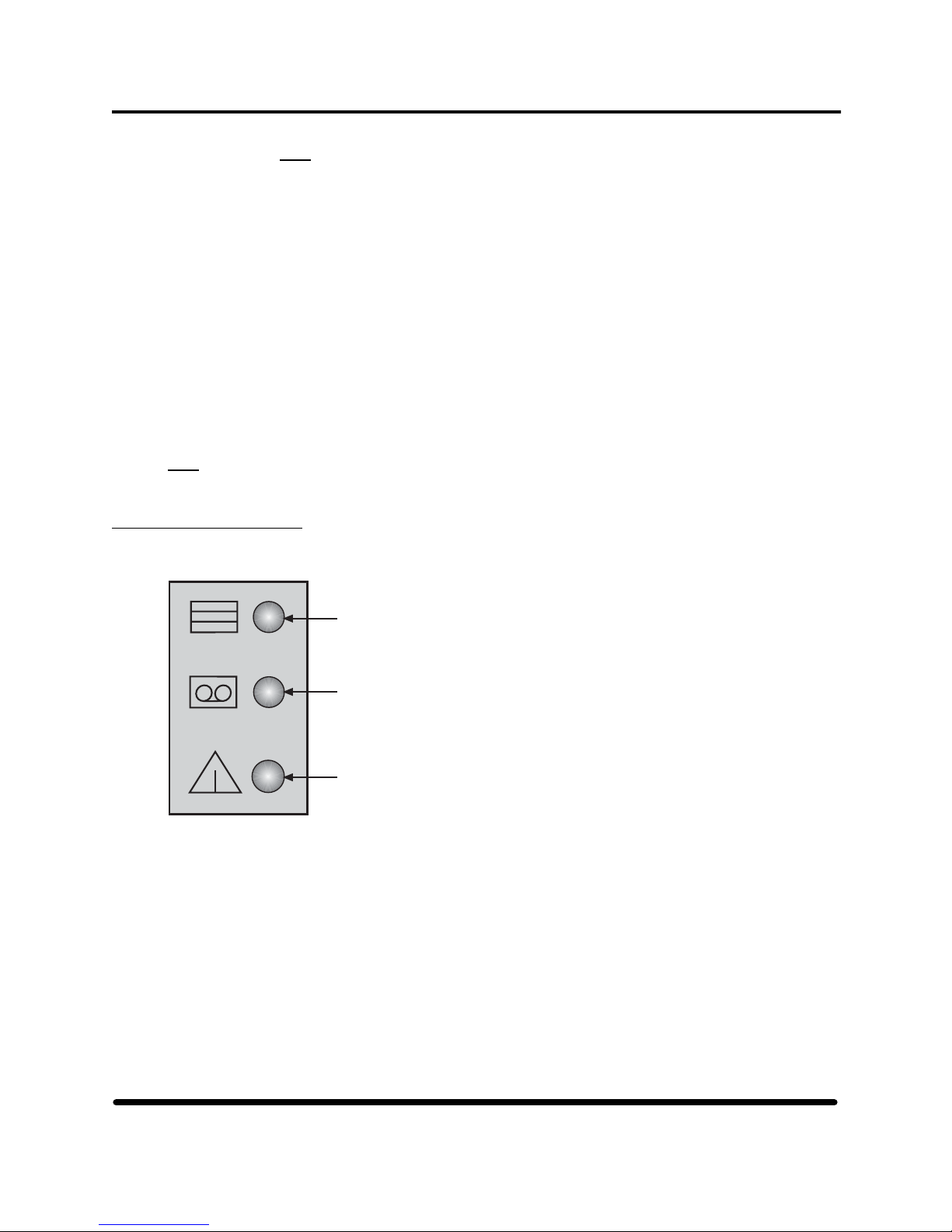
Section 3: HP 5242-ACL Tape Drive
Note: If the you urgently need to unload a cartridge, even at the risk of losing data, you
must force an eject.
2.6.1 Hold the Eject Button down for at least 5 seconds. The autoloader's LCD displays Force Eject.
2.6.2 The autoloader waits 35 seconds to give the normal eject procedure a chance to occur.
2.6.3 Once this time elapses and a tape is loaded in the tape drive, the tape immediately unthreads and
the cartridge ejects, regardless of what operation the tape drive was performing. The cartridge is
then placed in its slot in the magazine, and the tape drive resets as though the power had been
cycled.
Because the force eject might interrupt operation, the tape drive might not write EOD before the
cartridge ejects. This situation causes loss of data, and results in a cartridge with an invalid format.
2.6.4 If no cartridge is loaded in the tape drive, the autoloader waits 35 seconds, then begins the process
of ejecting the magazine. The autoloader resets as though power had been cycled.
: A forced eject overrides any SCSI Prevent Media Removal that is in effect and might abort any
Note
SCSI operations that are in progress on the autoloader.
2.7 Front Panel LEDs
The autoloader has three front panel LEDs that indicate how the autoloader is working. (See Figure 32.)
Magazine Present LED
T ape Activity LED
Operator Attention Required LED
Figure 32 Autoloader LEDs
HP StorageWorks DAT 72 (Models 5242 and 5242-ACL) User's Guide 37 HP Part Number 528296-03 July 2005
Page 45

Section 3: HP 5242-ACL Tape Drive
2.7.1 Magazine Present (Top LED)
2.7.1.1 This LED remains a steady green when a cartridge magazine is installed in the
autoloader.
2.7.1.2 The LED flashes green when a magazine is in the process of being installed, checked, or
ejected.
2.7.2 Tape Activity (Middle LED)
2.7.2.1 Steady green indicates that a cartridge is present in the drive.
2.7.2.2 Fast (4 times/second) flashing green means data is either being written or read, or that
activity other than the cartridge being loaded or unloaded is occurring.
2.7.2.3 Slow (2 times/second) flashing green means that the cartridge is being loaded or
unloaded.
2.7.3 Operator Attention Required (Lower LED)
2.7.3.1 Steady amber indicates that a serious hardware error has occurred. The tape drive should
be replaced. Call the GCSC.
2.7.3.2 Flashing amber indicates that a user-recoverable error has occurred. These errors are
shown in table 12. A slow flash rate is one cycle per second, medium is twice per second,
and fast is four times a second. The message shown on the top line of the drive's front
panel LCD area should help identify the problem.
Flash Meaning
Slow Hard fault condition that the drive cannot clear
Slow There is a tape in the autoloader but no magazine
Slow Front panel door is open when it should not be
Medium Drive heads need to be cleaned
Medium Tape is nearing the end of its useful life
Fast Firmware upgrade is taking place
Table 12 Operator attention required LED
2.8 Self-Test Display
2.8.1 During power-up, the tape drive executes a self-test diagnostic sequence. All three front panel lights
flash at 2 cycles per second.
2.8.2 If the self-test fails, the Operator Attention Required LED changes to steady amber, and the other
LEDs go off.
is present
HP StorageWorks DAT 72 (Models 5242 and 5242-ACL) User's Guide 38 HP Part Number 528296-03 July 2005
Page 46

Section 3: HP 5242-ACL Tape Drive
Chapter Three
3.1 Display Regions on the Autoloader
Figure 33 Autoloader LCD
: This display shows all the LCD sections might occur. Not all would show at any given time.
Note
1 The 10-character dot matrix display provides information on the autoloader's operating status and
potential error conditions. (For the types of message that appear here see Section 3.3 on this page.
2 The 7-segment display shows the number of the cartridges currently loaded in the drive.
3 The letters DC and WP, in the center of the LCD show if data compression is being used for
writing or if the cartridge is write-protected.
4 Numbered boxes on the right of the LCD individually light to indicate which magazine slots
contain a cartridge.
5 The odometer lines at the bottom of the LCD show how much tape remains in the current
partition. The more lines show, the less tape capacity remains.
3.2 Diagnostic Display
The purpose of the diagnostic firmware is to test the autoloader's electronics for functionality. During
power-up, the drive executes a self-test diagnostic sequence where all three LEDs flash twice a second. If
the self-test fails, the Operator Attention Required LED changes to steady amber and the other LEDs go
off.
3.3 LCD Categories of Information:
Three categories of messages can be displayed on the front panel:
1. Normal autoloader operating status information
2. Information messages
3. Error messages
HP StorageWorks DAT 72 (Models 5242 and 5242-ACL) User's Guide 39 HP Part Number 528296-03 July 2005
Page 47

Section 3: HP 5242-ACL Tape Drive
3.3.1 Normal Autoloader Operating Status Messages
3.3.1.1 Status messages that appear on the LCD cover five functional fields of the autoloader's
operation. Only one field at a time controls the LCD text display. The function fields
always appear in this order.
Functional
Field
Meaning
Reset
Firmware
Upgrade State
Magazine
Load State
Cartridge
Load State
Tape Motion
State
At power on, the Reset state has control of the LCD.
After the self-test has been passed, this state has
control of the LCD if a firmware upgrade is taking
place.
If no upgrade is being performed, control of the
LCD passes to the Magazine Load state, and
remains there until a magazine has been loaded.
After a magazine has been loaded, control of LCD
passes to the Cartridge Load state until a cartridge
has been moved to the drive and loaded.
Once a tape has been loaded, the Tape Motion
state covers activity involving the tape, including
reading and writing data.
Figure 34 Operating status messages
3.3.1.2 This chart (Figure 35.) shows the messages within each functional field and indicates
how control of the LCD passes to other fields. The messages in brackets do not appear on
the LCD because control has already passed to the next functional field.
Reset
State
Self T est
(Test O.K)
Firmware
Upgrade
State
FW Upgrade
FW Check
FW Program
New FW!!!!
(No Upgrade)
Magazine
Load
State
Insert Mag
Mag Check
Mag Eject
(Mag Loaded)
Cartridge
Load
State
Mag Loaded
SemiLoaded
Loading
Cleaning
FW T ape
(Tape Loaded)
Tape
Motion
State
Ready xxm
Read
Write x.y
Search>>
Search<<
Rewind
Format
Erase
Locate
Partition
Figure 35 Status message organization
HP StorageWorks DAT 72 (Models 5242 and 5242-ACL) User's Guide 40 HP Part Number 528296-03 July 2005
Page 48

Section 3: HP 5242-ACL Tape Drive
Note: If a write-protected tape is loaded, the Ready xxm message alternates with a Read Only message.
3.3.2 Information Messages
Informational messages appear when power is applied to the autoloader identifying its identity,
SCSI ID, and configuration. They also confirm when you have pressed the front panel buttons.
: The SCSI ID of the autoloader is not the same SCSI ID that you can select using the 5242-ACL
Note
LCD and mode switch. The autoloader's SCSI ID Is set to 0 and is not selectable.
3.3.3 Autoloader Error Messages
The LCD shows a range of error messages relating to the autoloader's operation. If a fault is detected
with the autoloader mechanism or data is at risk, the error message might be accompanied by a lit
Operator Attention Required LED. A alphabetical listing of messages is provided in Section 3.4 on
this page. Where possible, actions that you can take to recover from an error are also noted.
3.4 LCD Messages:
3.4.1 The OAR column indicates the state of the Operator Attention Required LED on the autoloader's
front panel while the message is being displayed.
3.4.2 The Type column can present one of three letters:
E Error message
I Informational message
S Status message
Table 13 Front panel messages
Message Type OAR Meaning Action
At BOD Error On A SPACE command
unexpectedly encountered
BOD. The tape is now
positioned at BOD
At EOD Error On A READ or SPACE
command encountered the
EOD area unexpectedly.
The tape is now positioned
at EOD.
Bad Media Error Flashing A READ or SPACE
command has failed
because the tape is not in
DDS format.
C7438 Info The product identifier. It is
displayed for 2 seconds
during power-up.
HP StorageWorks DAT 72 (Models 5242 and 5242-ACL) User's Guide 41 HP Part Number 528296-03 July 2005
Unload the tape and
use a DDS-certified
(Media Recognition
System) tape.
Page 49

Section 3: HP 5242-ACL Tape Drive
Clean Me Error Flashing A high error rate has been
detected reading or writing.
Insert a cleaning
cartridge to clean the
tape heads.
Config: xxy
Note:
For the
5242ACL
xxy is
factory
configured
at "FF1"
Close Door Error Flashing The front panel door is
Drive
Comms
Error
Eject Fail Error Flashing An eject command has
Info This indicates the value of
the switches used to
configure the drive for
different host systems. xx
is the hexadecimal value of
the Configuration Switches
on the underside of the
autoloader, and y the value
of the Autoloader Option
Switches on the rear panel.
During the power-up
sequence, it is displayed
for 2 seconds following the
SCSI ID.
open. Any autoloader
motion will be delayed.
Error On The drive has stopped
communicating with the
changer mechanism.
failed, either after you
pressed the Eject button or
after a host command.
Probably a magazine
that is partially inserted
through the door. Push
the magazine fully in
or remove it.
Contact the HP GCSC.
Try forcing ejection.
Eject Mag Info This is displayed when you
press the Eject button.
Error X Error Flashing The mechanism has
jammed. X gives the
reason for the jam.
ForceEject Info A forced ejection is in
progress.
Format Status A SCSI command for
generating a one- or twopartition tape is being
executed, or the drive is
changing the size of the
partitions on an existing
two-partition tape.
HP StorageWorks DAT 72 (Models 5242 and 5242-ACL) User's Guide 42 HP Part Number 528296-03 July 2005
Press the Eject button
to attempt to recover
cartridge and
magazine. If the
problem persists, note
the value of X and call
the HP GCSC.
Page 50

Section 3: HP 5242-ACL Tape Drive
FRU 1 Dead Error On The controller board for the
embedded drive has failed
its self-test.
Call the HP GCSC.
FRU 2 Dead Error On The drive mechanism has
FW Check Status Firmware upgrade data is
FW Data
Err
FW
Upgrade
FW Read
Fail
FW Tape
Write
Protected
FW Write
Fail
Error Flashing The autoloader has failed
Status Firmware upgrade data is
Error Flashing A firmware upgrade failed
Error Flashing A firmware upgrade failed
Error Flashing A firmware upgrade failed
failed its self-test.
being checked for
compatibility.
to upgrade the drive
firmware because the new
firmware is corrupt.
being read either through a
tape or the SCSI bus.
because of an error in
reading data from the tape.
because the tape is writeprotected.
because of an error in
writing a modified upgrade
count to the tape.
Call the HP GCSC.
Obtain a good copy of
the firmware upgrade.
Try again. If it still
fails, call the HP
GCSC.
Change the writeprotect switch on the
tape and try again.
Try again. If it still
fails, call the HP
GCSC.
Illegal FW Error Flashing The autoloader has failed
to upgrade the drive
firmware because the new
firmware is incompatible.
Illegal HW Error Flashing The autoloader has failed
to upgrade the drive
firmware because the new
firmware is for
incompatible hardware.
Insert Mag Status The autoloader is waiting
for you to insert a
magazine.
Load Tape Info Displayed when you press
the Load Tape button.
Loading Status Either a cartridge is being
moved from the magazine
and placed into the drive
mechanism, or the drive is
loading a cartridge.
HP StorageWorks DAT 72 (Models 5242 and 5242-ACL) User's Guide 43 HP Part Number 528296-03 July 2005
Obtain a correct
version of the firmware
upgrade.
Obtain a correct
version of the firmware
upgrade.
Page 51

Section 3: HP 5242-ACL Tape Drive
Locate Status The drive is moving the
tape to a point specified by
the host.
Mag Check Status The autoloader is
Mag Eject Status The autoloader is ejecting
Mag Loaded Status A magazine is loaded and
New FW!!!! Status The firmware upgrade
No
EODmark
Partition Status The drive is switching to
Partition 1
too large
Error Flashing The drive is trying to read
Error On A command to format the
examining the magazine to
discover occupied slots.
the magazine.
the magazine check has
been carried out.
process has been
successfully completed.
what appears to be a blank
tape (one with no DDSformat EOD pattern).
Probably a result of a
power-fail while writing.
the other partition on a
two-partition tape.
tape has failed because the
request size for partition 1
is too large.
Try again with a
smaller partition 1 or,
if possible, a longer
tape.
Read Status The drive is reading data
from the tape.
Read Fail Error Flashing A read has failed. The host
should reposition and try
again.
Rewind Status The drive is rewinding the
tape to the beginning of
partition.
SCSI Error Error On A SCSI command error has
been detected.
SCSI ID: x Info x indicates the SCSI ID of
the autoloader. During the
power-on sequence, it
displays for 2 seconds
following the product
identifier.
HP StorageWorks DAT 72 (Models 5242 and 5242-ACL) User's Guide 44 HP Part Number 528296-03 July 2005
Check the SCSI
interface connection
and try again.
Page 52

Section 3: HP 5242-ACL Tape Drive
Search << Status The drive is searching for a
record, filemark, setmark,
or BOD toward the
beginning of the tape that
is responding to a SCSI
SPACE command with a
negative count field.
Search >> Status The drive is searching for a
Select Tape Info Displayed when you press
Self Test Status The autoloader is
Stray Tape:
Insert
Empty Mag
Tape Fault Error Flashing The cartridge in the drive is
Info There is a cartridge in the
record, filemark, setmark
or EOD toward the end of
the tape that is responding
to a SCSI SPACE
command with a positive
count field.
the Select button and for a
short time after the button
is released.
performing its power-on
self-test.
autoloader but there is no
magazine present to put it
in.
faulty, possibly because the
tape has snapped, or the
cartridge has an invalid
pattern of identification
holes.
Insert an empty
magazine to retrieve
the cartridge.
Use a new cartridge
and ensure that it is
Media Recognition
System.
Tape Full Error On A READ, SPACE,
Tape has
DC data
HP StorageWorks DAT 72 (Models 5242 and 5242-ACL) User's Guide 45 HP Part Number 528296-03 July 2005
Error On A READ command has
WRITE, or WRITE
FILEMARKS command
encountered EOP. When
reading, this might mean
the required data is on the
next cartridge in sequence.
encountered compressed
data on the tape, but the
drive is not currently
configured to decompress
data. The host might have
disabled data compression,
or Configuration Switch 2
(on the underside of the
autoloader) is off so the
host ability to control the
drive's state is disabled.
Check that the host has
not disabled
compression. Check
that switch 2 is on by
reconfiguring the drive
using the Configuration
Switches on the
underside of the
autoloader.
Page 53

Section 3: HP 5242-ACL Tape Drive
Tape
Position
Lost
Error Flashing A WRITE, READ,
SPACE, or REWIND
command has failed to
complete. The tape is
positioned on the far side
of the bad group of data.
Reposition and try
again.
Unloading Status Either the drive is
unloading a cartridge, or a
cartridge is being ejected
from the drive and replaced
in the magazine.
UpgradeErr Error Flashing The autoloader has failed
to download an upgrade of
the firmware via SCSI.
Worn Media Error Flashing A high error rate has been
detected while writing,
suggesting that the tape is
nearing the end of its
useful life.
Write x.y Status The drive is writing data to
tape. x.y:1 is the
cumulative compression
ratio since power-on, or
since the compression ratio
was lasted cleared, for
example, Write 2.1" means
a compression ratio of
2.1:1. The compression
ratio is only displayed after
about 1 megabyte of data
has been written since
power-on.
Check the SCSI
connection and try
again.
Copy any data you
want to keep from the
cartridge onto a new
cartridge and discard
the old cartridge.
Write
Protected
Tape
Write Fail Error Flashing A WRITE, WRITE
HP StorageWorks DAT 72 (Models 5242 and 5242-ACL) User's Guide 46 HP Part Number 528296-03 July 2005
Error Flashing A WRITE, WRITE
FILEMARK, or ERASE
command has been
attempted on a writeprotected tape.
FILEMARK, or ERASE
command has failed.
Remove the tape and
change it to writeenabled.
Use a new cartridge.
Page 54

Section 3: HP 5242-ACL Tape Drive
Chapter Four
4.1 Upgrading the Tape Drive Firmware
The autoloader allows you to upgrade its firmware by inserting a firmware upgrade tape. The process takes
at least 3 minutes to complete. To upgrade the firmware by a tape load:
Caution
: Do not disconnect power to the autoloader at any time during the upgrade to avoid
corrupting the firmware in the autoloader.
1. Check that the tape drive is not engaged in any SCSI activity. The Tape Activity LED is off. It
is recommended that you first take the unit off-line and unplug the SCSI cable from the tape
drive.
2. Place the firmware upgrade tape into magazine slot 1. Insert the magazine into the autoloader.
3. About halfway through the upgrade process, the tape drive automatically ejects the cartridge
and the changer mechanism replaces it in the magazine. The magazine ejects.
4. When the LCD shows the message New FW!!!!, the firmware has been successfully upgraded.
Remove the firmware upgrade tape and replace it in its box.
HP StorageWorks DAT 72 (Models 5242 and 5242-ACL) User's Guide 47 HP Part Number 528296-03 July 2005
Page 55

Section 4: SCSI Bridge Electronics
SCSI Bridge Electronics
Chapter One
1.0 Controls and Indicators
4-Line LCD,
8-Characters per line
Mode
Switch
Section 4
Programmable
Error-Alert LED
Figure 36 Display unit controls and indicators
1.1 Mode Switch
The mode switch is located in the right, lower corner of the display unit. Use to select the SCSI ID, turn
compression on and off, access the off-line utilities, and perform the initial setup of the tape drive.
1.2 LEDs
The tape drive display unit has two LEDs, one green and one amber. The green LED indicates that data
compression is active. The amber LED is a user-programmable, error-alert indicator that lights when the
error-rate percentage reaches a predetermined value. To set this value or alter it, use the mode switch in
conjunction with the setup menus.
Compression
Indicator LED
Compression
Indicator LED
Mode
Switch
Programmable
Error-Alert LED
= Green
= Amber
Figure 37 Display unit LEDs
Warning: Using the LCD functionality to change operations or configuration
parameters without proper understanding can cause the 5242 to become nonoperational.
HP StorageWorks DAT 72 (Models 5242 and 5242-ACL) User's Guide 48 HP Part Number 528296-03 July 2005
Page 56

Section 4: SCSI Bridge Electronics
1.3 Front Panel LCD
A 4-line, 8-character-per-line, backlit liquid crystal display (LCD) provides you with performance
information, configuration selections, and diagnostic and special utility menus. During tape activity, the LCD
shows current tape-drive operation, a bar graph tracking tape capacity, and items such as total data transferred,
average transfer rate, compression ratio, ECC rate percentage, remaining tape capacity, and rewrite percentage.
When you enter the configuration, diagnostic, and utility menus, the LCD presents a series of items to choose
from and instructions to follow.
Write
E F
TOTL XFR
74MB
Sample Performance Display
Sample Configuration Display
SCSI ID:
]
[00
PRESS to
Alter
Figure 38 Front panel LCD
1.4 Understanding the Capacity Bar Graph
The capacity bar graph display updates dynamically during read and write operations. Beginning with the
native capacity of the cartridge (125m = 12.0 GB, 170m = 36.0 GB), as reported by the tape drive after a
cartridge is loaded. The SCSI bridge electronics applies the current average compression ratio (if any),
computes the then current maximum capacity, and displays the bar graph by incrementing or decrementing the
appropriate number of vertical bars between the empty icon and the full icon. There are thirty vertical bars,
each equating to approximately 3.33% of total capacity.
Empty Icon
Read
E F
ECC Rate
0.0%
Full Icon
Capacity
Indicators
Figure 39 Understanding the capacity bar graph
2.1 Introduction
The SCSI bridge electronics are at the heart of the display system that provides performance information
about the tape operation. In addition to bridging communications between the host and tape drive, the
electronics autonomously send commands to the tape drive to extract the data necessary for the display. A
high-performance processor and dual SCSI buses allow the unit to appear to the host as a tape device on the
host bus, and to interface with the tape drive as a new host on the tape bus. This private tape bus can operate
independently of a host to provide such capabilities as code-tape generation, code-tape loading and off-line
HP StorageWorks DAT 72 (Models 5242 and 5242-ACL) User's Guide 49 HP Part Number 528296-03 July 2005
Chapter Two
Page 57

Section 4: SCSI Bridge Electronics
drive testing. Other features of the SCSI bridge electronics include software configuration retained in
nonvolatile memory, flash memory for firmware upgrade, and low semiconductor parts count for reliability.
2.2 Initial LCD
After applying power to the tape drive, the SCSI bridge electronics attempt to access the drive at the selected
tape ID. Typically, tape drives require a few seconds to perform their self-test before they respond. The tape
drive is not selectable to the NonStop server during this period. If the tape ID has not been correctly selected
the tape drive will not complete its power-up sequence and remains inaccessible to the NonStop server. The
tape ID is set at the factory and is NOT user-selectable. If the tape drive fails to complete its power-up
sequence, contact the HP GCSC.
InFourmm
========
Power-on
SelfTest
Initial Power-Up Screen
Figure 40 LCD at startup
When the drive is accessed, the LCD presents the tape drive model identification and firmware level on the
top two lines, and the SCSI bridge electronics' product name, firmware level and host SCSI ID on the
bottom two lines. The tape drive is now selectable by the NonStop server at the host SCSI ID.
Figure 41 Identification of LCD items
This screen appears similar for the 5242 and 5242ACL models. The differences are:
Identification
5242 Display 5242ACL Display
Drive Product Identification Q1525A Q1566
Infourmm Firmware Level D72A D72B
Drive Firmware level V312 B312
2.3 Performance LCD Format
Upon receiving a TEST UNIT READY or INQUIRY SCSI command from the host, the LCD switches to
the performance format. This is the main operational format of the LCD. The top two lines of the LCD
always display the current SCSI command and the tape-capacity bar graph. The bottom two lines of the
display alternate between five performance/status items.
HP StorageWorks DAT 72 (Models 5242 and 5242-ACL) User's Guide 50 HP Part Number 528296-03 July 2005
Page 58

Section 4: SCSI Bridge Electronics
Figure 42 Tape drive performance LCD format
2.3.1 Current Tape Operation
The SCSI command being executed displays on the top line of the LCD. Typical commands shown
are Read, Write, WrtFMK, Rewind, Space, and so on.
Write
E F
TOTL XFR
74MB
Figure 43 Current tape operation display
Additionally, off-line utilities use this area to display tape-drive errors. The SCSI Request Sense
command provides information about an error.
2.3.2 Total Data Transferred
Total data bytes read or written from the tape drive appear with a KB (1024), MB (1024 x 1024)
or GB (1024 x 1024 x 1024) multiplier. On the first read or write command following a rewind,
the count is set to zero.
Write
E F
TOTL XFR
74MB
Figure 44 Total data transferred LCD
2.3.3 Transfer Rates in Kbytes per Second
The average transfer rate between the NonStop server and the tape drive is calculated by dividing
the total data transferred by the elapsed time since the first read or write command following a
rewind or write filemark.
HP StorageWorks DAT 72 (Models 5242 and 5242-ACL) User's Guide 51 HP Part Number 528296-03 July 2005
Page 59

Section 4: SCSI Bridge Electronics
Write
E F
XFR RATE
425KB/s
Figure 45 Transfer rate LCD
: Tape drives incorporate a data buffer to help maintain a constant data rate to the recording
Note
heads. When this buffer is empty, 1 MB of data or more can appear to be instantly written
to the tape drive and a correspondingly high transfer rate is displayed on the LCD. When
the buffer is sufficiently full, the recording heads are set in motion.
A substantial delay accompanies the first write operation to tape. This results in a drop in
the transfer rate. With continued writing to the tape drive, the tape constantly moves and the
average transfer rate approaches the quoted streaming rate.
2.3.4 Compression Ratio
Write
E F
COMPRESS
2.3:1
Figure 46 Compression ratio LCD
The average compression/decompression ratio shows as the ratio of the compressed and
uncompressed data lengths as reported by the tape drive. The ratio always appears in the format
XX:X.
2.3.5 Remaining Capacity
This value is an estimate of remaining tape capacity that is computed by multiplying the average
compression ratio by the remaining block count, which was obtained from the tape drive. KB, MB
and GB represent multipliers of 1024, 1024 x 1024, and 1024 x 1024 x 1024, respectively.
Read
E F
REMAIN'G
1.7GB
Figure 47 Remaining capacity readout
2.3.6 ECC/Rewrite Percentage
The number of ECC (when reading) or rewrite (when writing) occurrences, as a percentage of the
total number of read or write commands since the last rewind, appear in the format XX.X. In
general, error rates are the highest at the beginning of a tape because this part of the tape is written to
every time the tape unloads. When this area becomes worn, tapes become unreliable. Errors above
10.0 suggest worn tapes or the need to clean the recording heads.
HP StorageWorks DAT 72 (Models 5242 and 5242-ACL) User's Guide 52 HP Part Number 528296-03 July 2005
Page 60

Section 4: SCSI Bridge Electronics
C
Read
E F
ECC Rate
0.0%
Figure 48 ECC/Rewrite percentage displays
2.4 Setting Tape Density
Tape density format can be controlled by the SCSI bridge electronics or by the NonStop server. Some
applications will not function without having software control. When the appropriate drivers exist, the latter
method is preferred, and a setting of FF should be used (default setting). When the tape drive is not busy,
you can change the tape density by pressing the mode switch. Pressing the mode switch cycles the available
density settings. The options for tape density scroll on the LCD.
DEN=CO
Rev 0096
5170
T134 ID5
O = compression on
40 = compression off
a b c
Figure 49 Compression control screens
2.4.1 To enable compression
Press the mode switch when the LCD appears as shown in Figure 49a.
2.4.2 To disable compression
Press the mode switch when the LCD appears as shown in Figure 49b.
2.4.3 To enable host control of density
Press the mode switch when the LCD appears as shown in Figure 49c.
2.5 Setup Display Format
Configuration of the SCSI bridge electronics is accomplished using the LCD and the mode switch. All
configuration values are retained in nonvolatile memory. There are three setup menus. Setup 1 and Setup 2
contain configuration items, Setup 3 consists of diagnostic and special utilities. Enter the setup menus by
holding in the mode switch while powering up the subsystem. The menu display system forms this hierarchy:
Read
E F
RWr RATE
0.0%
DEN=40
Rev 0096
5170
T134 ID5
DEN=FF
Rev 0096
5170
T134 ID5
Valve should be
at FF only
HP StorageWorks DAT 72 (Models 5242 and 5242-ACL) User's Guide 53 HP Part Number 528296-03 July 2005
Page 61

Section 4: SCSI Bridge Electronics
*Set-Up*
Release
Button
to Start
Mode
Switch
Enter
Set-Up 1
PRESS to
Select
Enter
Set-Up 2
PRESS to
Select
Enter
Set-Up 3
PRESS to
Select
Exit
Set-Up
PRESS to
Select
Figure 50 Tape Drive setup menus
2.5.1 Setup Overview
2.5.1.1 Within each menu, the individual items generally take this format on the 4-line LCD:
Parameter
Instruction
SCSI ID:
[00]
PRESS to
Alter
LCD Setup Format
Figure 51 Tape drive LCD setup format
1. PARAMETER denotes the configuration being reviewed or edited.
2. SETTING (in SETUP 1 and SETUP 2) is the value that you can change.
3. INSTRUCTION describes what action should be taken if the mode switch is
pressed. If the mode switch is inactive for four seconds, the display changes. In
general, the menu system is designed to show continuously the current settings
with the instruction PRESS to Alter, which lets the operator alter the value.
2.5.2 Changing a Setting
Depending on the menu item, alter settings by the appropriate method that follows. When the
instruction reads PRESS to Alter, you have the option of exiting from the editing mode or
remaining in the editing mode to review the settings.
Setting
HP StorageWorks DAT 72 (Models 5242 and 5242-ACL) User's Guide 54 HP Part Number 528296-03 July 2005
Page 62

Section 4: SCSI Bridge Electronics
2.5.2.1 Numeric Entry Method
Enables you to change a setting by entering a decimal or hexadecimal number digit by
digit. The LCD shows the instruction PRESS to Incremnt. On the second line, the digit
to the right is highlighted and currently alterable. To increment the digit, press the mode
switch. Continue this process through all the sequentially highlighted digits. When the
highlight proceeds past the rightmost digit, the display shows PRESS if Done, allowing
you to confirm the change. If the numerical value requires additional editing, do not press
the mode switch. Wait until the highlight restarts at the leftmost digit and then continue
editing the setting.
SCSI ID:
[00]
PRESS to
Alter
SCSI ID:
[01]
PRESS to
Incremnt
SCSI ID:
[01]
PRESS if
Done
Figure 52 Numeric entry example
2.5.2.2 Pick Entry Method
Allows you to select from a predefined list of items. When PRESS to Scroll displays on
the LCD, you can view the list of items by pressing the mode switch. When the switch is
inactive for four seconds, the instruction PRESS if Done appears to allow you to confirm
the setting. If you want the setting, wait until the PRESS to Scroll instruction appears on
the LCD and then continue editing.
BaudRate
bps
9600
PRESS to
Alter
BaudRate
bps
9600
PRESS to
Scroll
BaudRate
1200 bps
PRESS to
Scroll
BaudRate
bps
2400
PRESS to
Scroll
Figure 53 Pick entry example
HP StorageWorks DAT 72 (Models 5242 and 5242-ACL) User's Guide 55 HP Part Number 528296-03 July 2005
BaudRate
bps
19K2
PRESS if
Done
Page 63

Section 4: SCSI Bridge Electronics
2.6 Setup 1 Configuration Display Format Items
Enter
Set-Up 1
PRESS to
Select
Tape
Term: On
*NOT sel
ectable*
SCSI ID:
[00]
PRESS to
Alter
Density:
[C0]
PRESS to
Alter
Tape ID:
[00]
*NOT sel
ectable*
Rwr% 0.5
Ecc: 0.5
PRESS to
Alter
Exit
Set-Up 1
PRESS to
Select
Figure 54 Setup 1 configuration items
2.6.1 Setting the host SCSI ID
SCSI ID:
[00]
PRESS to
Alter
SCSI ID:
[01]
PRESS to
Incremnt
SCSI ID:
[01]
PRESS if
Done
Figure 55 Setting the host SCSI ID
This configuration menu item sets the host SCSI ID used by the NonStop server to select the tape
drive. Enter a value (0 to 15) using the Numeric Entry Method. No two devices can have the same
SCSI ID on the host bus. For available SCSI Ids consult your system administrator.
: The ability to independently set the tape drive SCSI ID and the NonStop server SCSI ID is very
Note
useful. The tape drive ID can be altered from tape drive front panel without regard to the actual
physical SCSI ID of the drive itself, making SCSI device additions quick and simple.
2.6.2 Setting the Tape Drive SCSI ID
Tape ID:
[00]
*NOT sel
ectable*
Figure 56 Setting the tape drive ID
HP StorageWorks DAT 72 (Models 5242 and 5242-ACL) User's Guide 56 HP Part Number 528296-03 July 2005
Page 64

Section 4: SCSI Bridge Electronics
The tape drive SCSI ID is factory configured and is not user-selectable.
2.6.3 Setting the Tape Termination
Tape
Term:On
*NOT sel
ectable*
Figure 57 Setting the tape termination
Tape termination is factory-configured and is not user-selectable.
2.6.4 Selecting the Tape Density
Density:
[C0]
PRESS to
Alter
Density:
Density:
[00]
[00]
PRESS to
PRESS to
Incremnt
Incremnt
Density:
[F0]
PRESS to
Incremnt
Density:
[FF]
PRESS if
Done
Figure 58 Selecting the tape density
Tape density format can be controlled by the display unit or by the NonStop server. When the
appropriate drivers exist, the latter method is generally preferred and a setting of FF should be
used. These other density values allow the SCSI bridge electronics to control the tape density:
DAT Drives
C0 = Compressed mode
40 = Noncompressed mode
FF = Density controlled by the host software
: Once the settings have been configured through the setup menus, these settings become
Note
the default start-up values. Density can be changed on a tape-by-tape basis any time the
tape is at BOT during normal Performance Display operation. Pressing the mode switch
cycles the available density settings. Pressing the mode switch a second time selects the
setting. This setting is used until the unit is power cycled or reset. The setting selected in
the setup menu is then used as the default value.
HP StorageWorks DAT 72 (Models 5242 and 5242-ACL) User's Guide 57 HP Part Number 528296-03 July 2005
Page 65

Section 4: SCSI Bridge Electronics
2.6.5 Setting the Error-Alert (ECC/Rewrite Percentages) Thresholds
The SCSI bridge electronics allow you to set numeric percentage for error-alert thresholds that,
when exceeded, cause the amber LED (the lower LED on the tape drive front panel) to flash. Enter
thresholds by the Numeric Entry method. The rewrite threshold value is set first, followed by the
ECC threshold value. Entries take the form XX.X so you can enter values in the range of 00.0
percent to 99.9 percent. (It is recommended setting this threshold to a value of 10.0 percent.)
Lower values cause the amber LED to light to flash at a lower percentage of error occurrences.
: Because the beginning of tape is written to every time a tape is unloaded, this area of the
Note
tape tends to wear sooner than the rest of the tape. As a result, it is not unusual to
experience rewrites or ECC's at the beginning of tape. If these occur, the predetermined
thresholds can be exceeded early, but the percentage then drops below the threshold as
reading or writing moves further down the tape. To signal this, the error-alert LED
flashes when the error rates exceed the set values but returns to a steady illumination if,
once exceeded, the error rate falls below the set value.
Rwr% 0.5
Ecc:80.5
PRESS to
Alter
Rwr% 0.5
Ecc:80.5
PRESS to
Incremnt
Rwr%30.7
Ecc:80.5
PRESS to
Alter
Rwr%30.7
Ecc:20.5
PRESS to
Incremnt
Rwr%30.7
Ecc:24.2
PRESS if
Done
Rwr% 0.5
Ecc:80.5
PRESS to
Incremnt
Rwr%30.7
Ecc:24.5
PRESS to
Incremnt
Rwr%30.5
Ecc:80.5
PRESS to
Incremnt
Rwr%30.7
Ecc:24.2
PRESS to
Incremnt
Figure 59 Setting error-alert (ECC/Rewrite percentages) thresholds
HP StorageWorks DAT 72 (Models 5242 and 5242-ACL) User's Guide 58 HP Part Number 528296-03 July 2005
Page 66

Section 4: SCSI Bridge Electronics
2.7 Setup 2 Configuration Display Format Items
Enter
Set-Up 2
PRESS to
Select
Key:2.01
[
288FEA
*NOT sel
ectable*
BaudRate
bps
9600
PRESS to
Alter
]
ptions:
O
00001401
PRESS to
Alter
EM: --- NONE
*NOT sel
ectable*
Exit
Set-Up 2
PRESS to
Select
Figure 60 Setup 2 configuration items
2.7.1 Editing the Option Access Key
Key:2.01
[
*NOT sel
ectable*
288FEA
]
Figure 61 Editing the option access key
This option is factory configured and is not user-selectable.
2.7.2 Configuring the Options Setting
Options
00001400
PRESS to
Alter
Figure 62 Configuring the options setting
HP StorageWorks DAT 72 (Models 5242 and 5242-ACL) User's Guide 59 HP Part Number 528296-03 July 2005
Options
01001400
PRESS to
Incremnt
ptions:
O
00001400
PRESS if
Done
Page 67

Section 4: SCSI Bridge Electronics
If your configuration or NonStop server environment requires unique settings or special
configurations, HP can provide assistance and minor firmware configurations for specific platforms,
software or drives through the use of this menu item. This setting is factory-configured at 00001400
and you should never have to changed it. As noted, special situations may require this setting be
changed, but it is highly recommended that you contact your service provider before changing this
setting. Use the Numeric Entry Method to enter the eight-digit hex value.
2.7.3 Selecting a Baud Rate
BaudRate
bps
9600
PRESS to
Alter
BaudRate
bps
9600
PRESS to
Scroll
BaudRate
1200 bps
PRESS to
Scroll
BaudRate
bps
2400
PRESS to
Scroll
BaudRate
bps
19K2
PRESS if
Done
Figure 63 Selecting a baud rate
Four different baud rates are available for connecting to a serial terminal or terminal emulator: No parity, 8
data bits, 1 stop bit, and xon/xoff flow control. The 3-pin serial connector on the tape drive can connect to
a PC serial port by using a communication package such as PRO-COMM (with xon/xoff enabled) to
upgrade the flash firmware. Use the Pick Entry Method to select a baud rate.
2.8 Setup 3 Off-line Utilities Display Format Items
Enter
Set-Up 3
PRESS to
Select
Drive
Test
PRESS to
Run
Hdwr
Test
press
to run
Create a
CodeTape
PRESS to
Run
Load a
CodeTape
PRESS to
Run
Figure 64 Setup 3 off-line utilities menu
HP StorageWorks DAT 72 (Models 5242 and 5242-ACL) User's Guide 60 HP Part Number 528296-03 July 2005
Exit
Set-Up 3
PRESS to
Select
Page 68

Section 4: SCSI Bridge Electronics
Pressing the mode switch at this menu item invokes the drive self-test and offers a series of options from
which you can select. This standalone exerciser can be used to diagnose problems within the tape drive.
Modes of operation include fixed/variable block transfers, spacing, differing densities/compression modes,
and a means to control the running time. Records are written with interspersed filemarks, rewound and
read/verified. This cycle repeats for other densities supported by the tape drive. During the testing process,
you can observe the error rate. If after you use a new tape and clean the heads, a high error rate persists,
you might have a tape drive problem. Other errors might display the KEY/ASC/ASCQ bytes of a Request
Sense command that are described in your tape drive product manual.
2.8.1 Invoking the Drive Test Option
Enter
Set-Up 3
PRESS to
Select
Drive
Test
PRESS to
Run
10M
Fixd.Tst
PRESS to
Run
200M
Vari.Tst
PRESS to
Run
Custom
Tst
PRESS to
Select
1M
Fixd.Tst
PRESS to
Run
10M
Vari.Tst
PRESS to
Run
2.5G
Fixd.Tst
PRESS to
Run
Exit
Menu
PRESS to
Select
Figure 65 Drive self-test options
1M
Vari.Tst
PRESS to
Run
200M
Fixd.Tst
PRESS to
Run
2.5G
Vari.Tst
PRESS to
Run
HP StorageWorks DAT 72 (Models 5242 and 5242-ACL) User's Guide 61 HP Part Number 528296-03 July 2005
Page 69

Section 4: SCSI Bridge Electronics
Enter
Set-Up 3
PRESS to
Select
Drive
Test
PRESS to
Run
200M
Fixd.Tst
PRESS to
Run
200M
Fixd.Tst
PRESS to
Confirm
Write
E F
TOTL XFR
24MB
Write
E F
COMPRESS
2.3:1
Write
E F
REMAIN'G
1.9GB
200M
Fixd.Tst
PRESS to
Escape
200M
Fixd.Tst
Waiting
for Tape
Write
E F
XFR RATE
424KB/s
Write
E F
RWr Rate
0.0%
Pass
E F
REMAIN'G
1.9GB
Figure 66 Example drive test
HP StorageWorks DAT 72 (Models 5242 and 5242-ACL) User's Guide 62 HP Part Number 528296-03 July 2005
Press to Return
to Self Test Menu
Page 70

Section 4: SCSI Bridge Electronics
Enter
Set-Up 3
PRESS to
Select
Drive
Test
PRESS to
Run
Variable
Mode
PRESS to
Toggle
Ready to
Run
PRESS to
Escape
Write
E F
TOTL XFR
1024MB
Write
E F
RWr RATE
0.0%
Custom
Test
PRESS to
Select
Run
Once
PRESS to
Toggle
Ready to
Run
PRESS to
Confirm
Write
E F
XFR RATE
301KB/s
Write
E F
REMAIN'G
1.8
1MB
to Xfer
PRESS to
Increment
Ready to
Run
PRESS to
Start
Ready to
Run
Waiting
for tape
Write
E F
COMPRESS
1.0:1
Pass
E F
REMAIN'G
1761MB
Figure 67 Example custom drive test menu
HP StorageWorks DAT 72 (Models 5242 and 5242-ACL) User's Guide 63 HP Part Number 528296-03 July 2005
Press to Return
to Self Test Menu
Page 71

Section 4: SCSI Bridge Electronics
2.8.2 Activating a Hardware Self-Test
Enter
Set-Up 3
PRESS to
Select
Hdwr
Test
press
to run
Figure 68 Activating a hardware self-test
2.8.3 Making a Code Tape
Enter
Set-Up 3
PRESS to
Select
Hdwr
Test
Testing
Scsi
Hdwr
Test
Ram Test
& Reset
InFourmm
========
Power On
SelfTest
C7438A
Rev L610
5170
T133BID5
Create a
CodeTape
PRESS to
Run
Figure 69 Making a code tape
HP StorageWorks DAT 72 (Models 5242 and 5242-ACL) User's Guide 64 HP Part Number 528296-03 July 2005
Create a
CodeTape
PRESS to
Confirm
Create a
CodeTape
PRESS to
Escape
Create a
CodeTape
waiting
for tape
Load
Tape
Page 72

Section 4: SCSI Bridge Electronics
The SCSI bridge electronics firmware may be copied to another tape drive by making a Code
Tape. Configuration settings are not carried across but must be entered manually. You are
prompted to insert a scratch tape. During operation the Performance Display appears and 64Kb
transfers displays on the LCD. The tape unloads and you are returned to the menu system.
2.8.4 Loading a Code Tape
Enter
Set-Up 3
PRESS to
Select
Load a
CodeTape
PRESS to
Run
Load a
CodeTape
PRESS to
Confirm
Load a
CodeTape
PRESS to
Escape
Load a
CodeTape
waiting
for tape
Load
Tape
Figure 70 Loading a code tape
The SCSI bridge electronics firmware can be upgraded by using a Code Load Tape. You are
prompted to insert the tape. Do not disturb the unit's power until the end of the procedure. The SCSI
bridge electronics relocate some internal firmware, switch to the Performance Display format, read
64Kb, and verifies the tape, rewinds the tape, rereads the 64Kb, programs the firmware and, unloads
the tape when complete. You are not be returned to the menu system because this utility alters the
RAM/ROM in a non recoverable manner. A cold reset executes.
: For this procedure, it is recommended that you take the tape drive off-line and disconnect
Note
the SCSI cable from the rear connector of the tape drive.
HP StorageWorks DAT 72 (Models 5242 and 5242-ACL) User's Guide 65 HP Part Number 528296-03 July 2005
Page 73

Section 4: SCSI Bridge Electronics
5242 Tape Drive
Bringing Online 29
Cartridge
Loading 70
Unloading 71
Controls and Indicators 72
Features 69
Installation 22
AC Power 22
SCSI Cable 24
Interfaces 64
Components 4
Introduction 68
LEDs 73
Maintenance
Enclosure 59
Head Cleaning xxii, 54
LCD 59
Power Requirements 19
Power-Up Sequence 31
SCSI Cable 6
SCSI ID, Setting and Checking 34
Specifications
Electrical 63
Environmental 64
LCD 63
Physical 65
SCSI Cable 64
Transfer Rates
Burst 12
Starting 38
Testing 39
Troublehooting 40
5242ACL Tape Drivem
Autoloader LCD
Bringing Online 29
Cartridges and Magazines 83
Diagnostic Display 92
Features 81
Front Panel LEDs
Installation 22
Introduction 80
LEDs 88
Magazine, Ejecting 86
Magazine, Forcing an Ejection 87
Magazine, Loading 84
Maintenance
Power Requirements 19
Power-Up Sequence 32
SCSI Cable 6
SCSI ID, Setting and Checking 34
Specifications
Sustained 12
Categories of Information 92
Display Regions 91
Categories of Information
Error Messages 95
Normal Status 93
Operation 82
Terminology 82
Magazine Present 89
Tape Activity 89
AC Power 22
SCSI Cable 24
Interfaces 64
Components 4
Enclosure 59
Head Cleaning xxv, 57
LCD 59
Electrical 63
Environmental 64
LCD 63
Physical 65
Index
Transfer Rates
Burst 12
Starting 38
Testing 39
Troubleshooting 40
Agency Approvals 64
Burst Transfer Rates 12
Component Part Numbers 7
DAT72
Display Unit, specifications 63
HP Processor Multifunction (PMF 5
HP NonStop servers
Configuring 43
Installation
SCF
Interfaces 64
Components 4
LEDs
5242 Tape Drive 73
5242ACL Tape Drive 88
PMF FRU Configuration Form 45
Power Requirements 19
Processor Multifunction (PMF) 5
SCF
Adding a Tape Drive 48
Deleting a Tape Drive 52
Tape Drive Attributes 50
SCSI Cable
Connecting to the Tape Drive 24
Connecting to the PMF 26
Copper (PMF FRU) 6
Cable Length Limiations 62
Length Limitations 64
SCSI Compatibility 13
SCSI ID, Setting the ID 124
Specifications 63
Agency Approvals 64
Electrical 63
Environmental 64
Physical 65
Sustained Transfer Rates 12
Sustained 12
5242 and 5242ACL
Online Using SCF 47
Using the SCF 50
Group 43
Identifying CRUs 44
Group Number 44
Model Number 44
Slot Number 44
Module 43
PMF CRU Configuration Form 45
Slot 44
5242 and 5242ACL
AC Power 22
Bringing Online 29
Checking & Setting the SCSI ID 34
Power-Up 31
Power-Up Sequence 32
SCSI Cable 24
Starting 38
Testing 39
Troubleshooting 40
5242 and 5242ACL Tape Drives 15, 22
Overview 15
Planning Requirements 16
AC Power 19
Environmental 18
Physical Specifications 17
Service Clearance 17
Adding a Tape Drive 48
Deleting a Tape Drive 52
Tape Drive Attributes 50
HP StorageWorks DAT 72 (Models 5242 and 5242-ACL) User's Guide 66 HP Part Number 528296-03 July 2005
Page 74

Safety and Compliance
Tape
Cartridge 8
Capacity 11
Cleaning Tape 8
Compatibility 13
Humidity 8
Labeled and Unlabeled Tapes 11
Life Expectancy 9
Using Labels 9
Write-Protecting 10
Tape Drive Specifications
63
HP StorageWorks DAT 72 (Models 5242 and 5242-ACL) User's Guide 67 HP Part Number 528296-03 July 2005
Page 75

Safety and Compliance
Safety and Compliance
Regulatory Compliance Statements
This section contains three types of required safety and compliance statements:
• Ρεγυλατορψ χοµπλιανχε
• Ωαστε Ελεχτριχαλ ανδ Ελεχτρονιχ Εθυιπµεντ (ΩΕΕΕ)
• Σαφετψ
Regulatory Compliance Statements
The following regulatory compliance statements apply to the products documented by this manual.
FCC Compliance
This equipment has been tested and found to comply with the limits for a Class A digital device, pursuant to
part 15 of the FCC Rules. These limits are designed to provide reasonable protection against harmful
interference when the equipment is operated in a commercial environment. This equipment generates, uses,
and can radiate radio-frequency energy and, if not installed and used in accordance with the instruction
manual, may cause interference to radio communications. Operation of this equipment in a residential area is
likely to cause harmful interference in which case the user will be required to correct the interference at his
own expense.
Any changes or modifications not expressly approved by Hewlett-Packard Computer Corporation could void
the user’s authority to operate this equipment.
Canadian Compliance
This class A digital apparatus meets all the requirements of the Canadian Interference-Causing Equipment
Regulations.
Cet appareil numérique de la classe A respecte toutes les exigences du Règelment sur le matériel brouilleur
du Canada.
Korea MIC Compliance
HP StorageWorks DAT 72 (Models 5242 and 5242-ACL) User's Guide 68 HP Part Number 528296-03 July 2005
Page 76

Safety and Compliance
Taiwan (BSMI) Compliance
Japan (VCCI) Compliance
This is a Class A product based on the standard or the Voluntary Control Council for Interference by
Information Technology Equipment (VCCI). If this equipment is used in a domestic environment, radio
disturbance may occur, in which case the user may be required to take corrective actions.
European Union Notice
Products with the CE Marking comply with both the EMC Directive (89/336/EEC) and the Low Voltage
Directive (73/23/EEC) issued by the Commission of the European Community.
Compliance with these directives implies conformity to the following European Norms (the equivalent
international standards are in parenthesis):
• ΕΝ55022 (ΧΙΣΠΡ 22)Ελεχτροµαγνετιχ Ιντερφερενχε
• ΕΝ55024 (ΙΕΧ61000−4−2, 3, 4, 5, 6, 8, 11)Ελεχτροµαγνετιχ Ιµµυνιτψ
• ΕΝ61000−3−2 (ΙΕΧ61000−3−2)Ποωερ Λινε Ηαρµονιχσ
• ΕΝ61000−3−3 (ΙΕΧ61000−3−3)Ποωερ Λινε Φλιχκερ
• ΕΝ60950 (ΙΕΧ950)Προδυχτ Σαφετψ
HP StorageWorks DAT 72 (Models 5242 and 5242-ACL) User's Guide 69 HP Part Number 528296-03 July 2005
Page 77

Safety and Compliance
Laser Compliance
This product may be provided with an optical storage device (that is, CD or DVD drive) and/or fiber optic
transceiver. Each of these devices contains a laser that is classified as a Class 1 Laser Product in accordance
with US FDA regulations and the IEC 60825-1. The product does not emit hazardous laser radiation.
WARNING: Use the controls or adjustments or performance of
procedures other than those specified herein or in the laser product’s
installation guide may result in hazardous radiation exposure. To
reduce the risk of exposure to hazardous radiation:
•
∆ο νοτ τρψ το οπεν τηε µοδυλε ενχλοσυρε. Τηερε αρε νο υσ
ερ−σερϖιχεαβλε χοµπονεντσ ινσιδε.
•
∆ο νοτ οπερατε χοντρολσ, µακε αδϕυστµεντσ, ορ περφορµ
προχεδυρεσ το τηε λασερ δεϖιχε οτηερ τηαν τηοσε σπεχιφιεδ ηε
ρειν.
•
Αλλοω ονλψ ΗΠ Αυτηοριζεδ Σερϖιχε τεχηνιχιανσ το ρεπα
ιρ τηε µοδυλε.
The Center for Devices and Radiological Health (CDRH) of the U.S. Food and Drug Administration
implemented regulations for laser products on August 2, 1976. These regulations apply to laser products
manufactured from August 1, 1976. Compliance is mandatory for products marketed in the Unites States.
SAFETY CAUTION
The following icon or caution statements may be placed on equipment to indicate the presence of potentially
hazardous conditions:
HP StorageWorks DAT 72 (Models 5242 and 5242-ACL) User's Guide 70 HP Part Number 528296-03 July 2005
DUAL POWER CORDS CAUTION:
“THIS UNIT HAS MORE THAN ONE POWER SUPPLY CORD.
DISCONNECT ALL POWER SUPPLY CORDS TO COMPLETELY
REMOVE POWER FROM THIS UNIT."
"ATTENTION: CET APPAREIL COMPORTE PLUS D'UN CORDON
D'ALIMENTATION. DÉBRANCHER TOUS LES CORDONS
D'ALIMENTATION AFIN DE COUPER COMPLÈTEMENT
L'ALIMENTATION DE CET ÉQUIPEMENT".
DIESES GERÄT HAT MEHR ALS EIN NETZKABEL. VOR DER
WARTUNG BITTE ALLE NETZKABEL AUS DER STECKDOSE ZIEHEN.
Page 78

Safety and Compliance
Any surface or area of the equipment marked with these symbols
indicates the presence of electric shock hazards. The enclosed area
contains no operator-serviceable parts.
WARNING: To reduce the risk of injury from electric shock hazards, do
not open this enclosure.
DOUBLE POLE FUSING
CAUTION: DOUBLE-POLE /NEUTRAL FUSING.
ATTENTION: DOUBLE POLE/FUSIBLE SUR LE NEUTRE
NOT FOR EXTERNAL USE
CAUTION: NOT FOR EXTERNAL USE. ALL RECEPTACLES ARE FOR INTERNAL USE ONLY.
ATTENTION: NE PAS UTILISER A L’EXTERIEUR DE L’EQUIPEMENT
IMPORTANT: TOUS LES RECIPIENTS SONT DESTINES UNIQUEMENT A UN USAGE INTERNE.
VORSICHT: ALLE STECKDOSEN DIENEN NUR DEM INTERNEN GEBRAUCH.
HIGH LEAKAGE CURRENT
To reduce the risk of electric shock due to high leakage currents, a reliable grounded (earthed) connection
should be checked before servicing the power distribution unit (PDU).
Observe the following limits when connecting the product to AC power distribution devices: For PDUs that
have attached AC power cords or are directly wired to the building power, the total combined leakage
current should not exceed 5 percent of the rated input current for the device.
“HIGH LEAKAGE CURRENT, EARTH CONNECTION ESSENTIAL BEFORE CONNECTING
SUPPLY”
“HOHER ABLEITSTROM. VOR INBETRIEBNAHME UNBEDINGT ERDUNGSVERBINDUNG
HERSTELLEN”
“COURANT DE FUITE E’LEVE’. RACCORDEMENT A LA TERRE INDISPENSABLE AVANT LE
RACCORDEMENT AU RESEAU”
FUSE REPLACEMENT
CAUTION – For continued protection against risk of fire, replace only with same fuse type TCF15, Rated
600V~, 15A. Disconnect power before changing fuses.
Waste Electrical and Electronic Equipment (WEEE)
Information about the Waste Electrical and Electronic Equipment (WEEE) directive can be accessed from
the left navigation area of the NTL home page: select NonStop Computing > Waste Electrical and
Electronic Equipment (WEEE).
HP StorageWorks DAT 72 (Models 5242 and 5242-ACL) User's Guide 71 HP Part Number 528296-03 July 2005
Page 79

Safety and Compliance
Important Safety Information
Safety information can be accessed from the left navigation area of the NTL home page: select NonStop
Computing>Important Safety Information. A document window containing a binder of safety
information, in several languages, appears. In the document window, click a document title to open the
safety information in another language. Local HP support can also help direct you to your safety
information.
HP StorageWorks DAT 72 (Models 5242 and 5242-ACL) User's Guide 72 HP Part Number 528296-03 July 2005
 Loading...