

Page 1
HP Kayak
PC Workstation
Service Handbook
PC Workstations and
Accessories
4th Edition
June 2000
Page 2
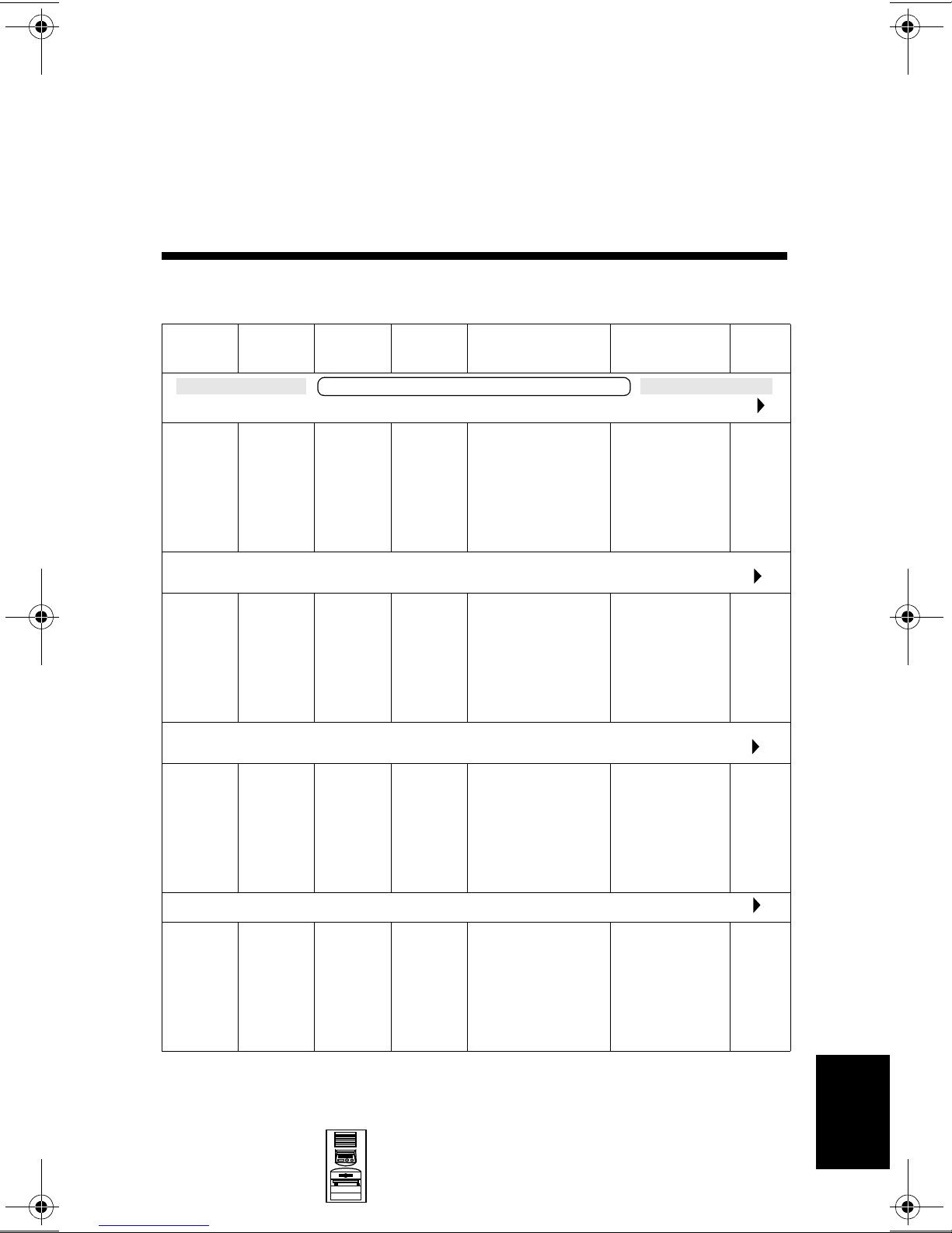
HP Kayak XA Minitower
Series 05xx PC Workstations
Models and Accessories
10
Product
Number
HP Kayak XA Series 0503 PC Workstation 6/400 MHz 100 FSB
D6724N
and
D6724T
HP Kayak XA Series 0503 PC Workstation 6/400 MHz 100 FSB (CPL: 10/98 )
D6725N
and
D6725T
HP Kayak XA Series 0541 PC Workstation 6/450 MHz 100 FSB (CPL: 10/98 )
D6727N
and
D6727T
HP Kayak XA Series 0562 PC Workstation 6/450
Cache
Memory
Pentium
II with
512 KB
of L2
cache
memory
Pentium
II with
512 KB
of L2
cache
memory
Pentium
II with
512 KB
of L2
cache
memory
Std.
RAM
HP Kayak XA 6/xxx PC Workstation
64 MB
SDRAM
100 MHz
non-ECC
64 MB
SDRAM
100 MHz
non-ECC
64 MB
SDRAM
100 MHz
non-ECC
Hard
Drive
6.4 GB
7.2 krpm
Ultra
ATA
9.1 GB
7.2 krpm
UltraWide
SCSI
9.1 GB
7.2 krpm
UltraWide
SCSI
Video Controller Multi-media LAN
Matrox
Millennium G200
8 MB video
memory fitted.
Upgradable to
16 MB of memory
Matrox
Millennium G200
8 MB video
memory fitted.
Upgradable to
16 MB of memory
ELSA GLoria
Synergy+ AGP,
8 MB on board,
not upgradeable
1
(CPL: 10/98 )
32✕ Max IDE
CD-ROM.
Bolero add-on
audio board.
32✕ Max IDE
CD-ROM.
Bolero add-on
audio board.
32✕ Max IDE
CD-ROM.
Bolero add-on
audio board.
2
MHz 100 FSB (CPL:12/98 )
None
10BT/
100BX
10BT/
100BX
D6728N
and
D6728T
Mini-Tower
PC Workstations
Pentium
II with
512 KB
of L2
cache
memory
128 MB
SDRAM
100 MHz
ECC
10.1 GB
7.2 krpm
IDE
Accel Galaxy AGP.
31 MB of video
memory. Not
upgradable.
HP Kayak XA Minitower Series 05xx PC
32✕ Max IDE
CD-ROM.
Bolero add-on
audio board.
Workstations
None
10-1
10
Page 3
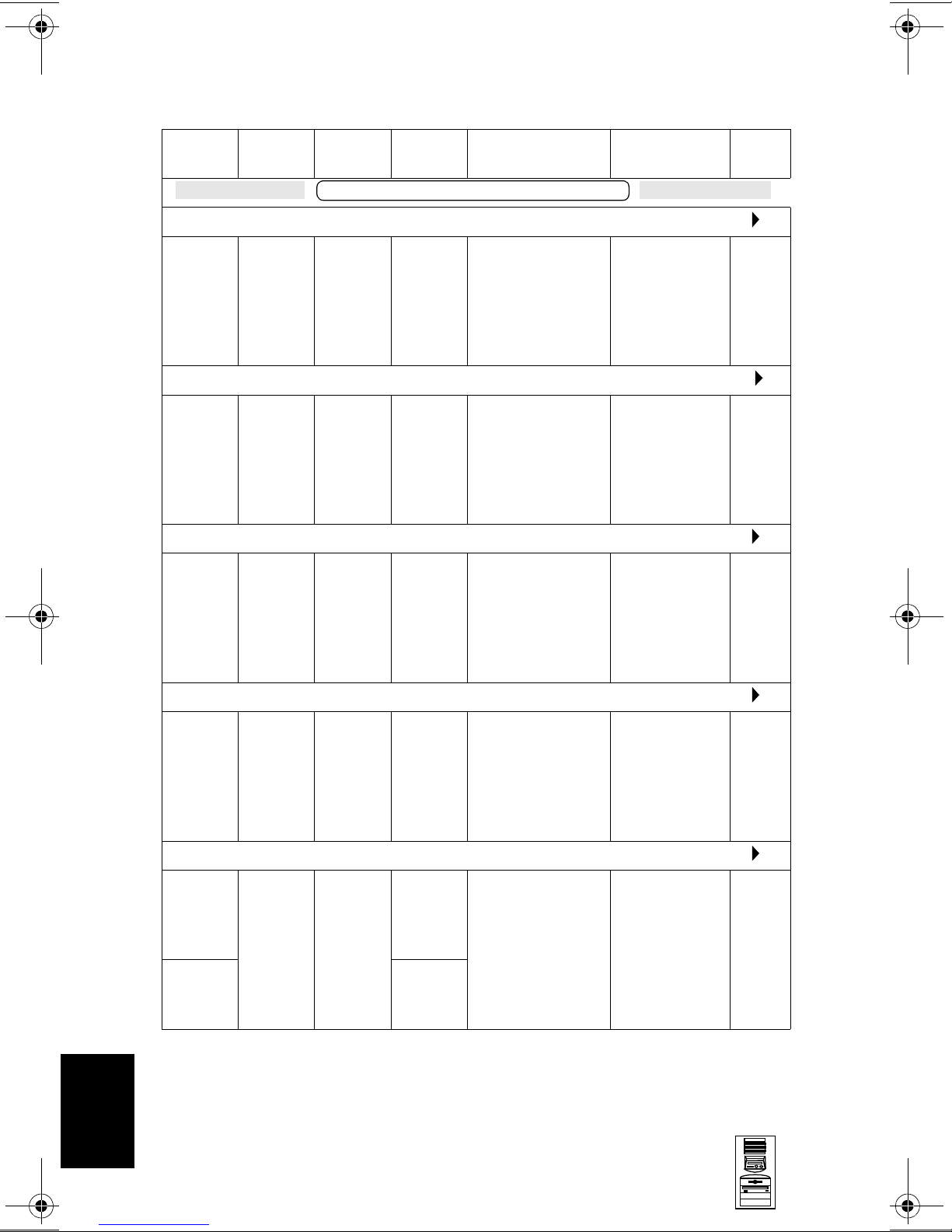
HP Kayak XA Minitower Series 05xx PC Workstations
Product
Number
HP Kayak XA Series 0503 PC Workstation 7/450 MHz 100 FSB (CPL: 03/99 )
D6730N
and
D6730T
HP Kayak XA Series 0562 PC Workstation 7/450
D6733N
and
D6733T
HP Kayak XA Series 0503 PC Workstation 7/500 MHz 100 FSB (CPL: 03/99 )
D6732N
and
D6732T
Cache
Memory
Pentium
III with
512 KB
of L2
cache
memory
Pentium
III with
512 KB
of L2
cache
memory
Pentium
III with
512 KB
of L2
cache
memory
Std.
RAM
HP Kayak XA 7/xxx PC Workstation
128 MB
SDRAM
100 MHz
ECC
128 MB
SDRAM
100 MHz
ECC
128 MB
SDRAM
100 MHz
ECC
Hard
Drive
6.4 GB
7.2 krpm
Ultra
ATA
10.1 GB
7.2 krpm
IDE
9.1 GB
7.2 krpm
UltraWide
SCSI
Video Controller Multi-media LAN
Matrox
Millennium G200
8 MB video
memory fitted.
Upgradable to
16 MB of memory.
Accel Galaxy AGP.
31 MB of video
memory. Not
upgradable.
Matrox
Millennium G200
8 MB video
memory fitted.
Upgradable to
16 MB of memory.
32✕ Max IDE
CD-ROM.
Bolero add-on
audio board.
2
MHz 100 FSB (CPL: 03/99 )
32✕ Max IDE
CD-ROM.
Bolero add-on
audio board.
32✕ Max IDE
CD-ROM.
Bolero add-on
audio board.
None
None
10BT/
100BX
10
HP Kayak XA Series 0503 PC Workstation 7/500 MHz 100 FSB (CPL: 11/99 )
D6739N
and
D6739T
HP Kayak XA Series 0503 PC Workstation 7/550 MHz 100 FSB (CPL: 06/99 )
D6736N
and
D6736T
D6737N
and
D6737T
Pentium
III with
512 KB
of L2
cache
memory
Pentium
III with
512 KB
of L2
cache
memory
128 MB
SDRAM
100 MHz
ECC
128 MB
SDRAM
100 MHz
ECC
6.5 GB
7.2 krpm
Ultra
ATA
13.5 GB
7.2 krpm
Ultra
ATA
9.1 GB
7.2 krpm
SCSI
Matrox
Millennium G200
8 MB video
memory fitted.
Upgradable to
16 MB of memory.
Matrox
Millennium G200
8 MB video
memory fitted.
Upgradable to
16 MB of memory.
.
32✕ Max IDE
CD-ROM.
Bolero add-on
audio board.
32✕ Max IDE
CD-ROM.
Bolero add-on
audio board.
None
None
10-2
HP Kayak XA Minitower Series 05xx PC
Workstations
Mini-Tower
PC Workstations
Page 4
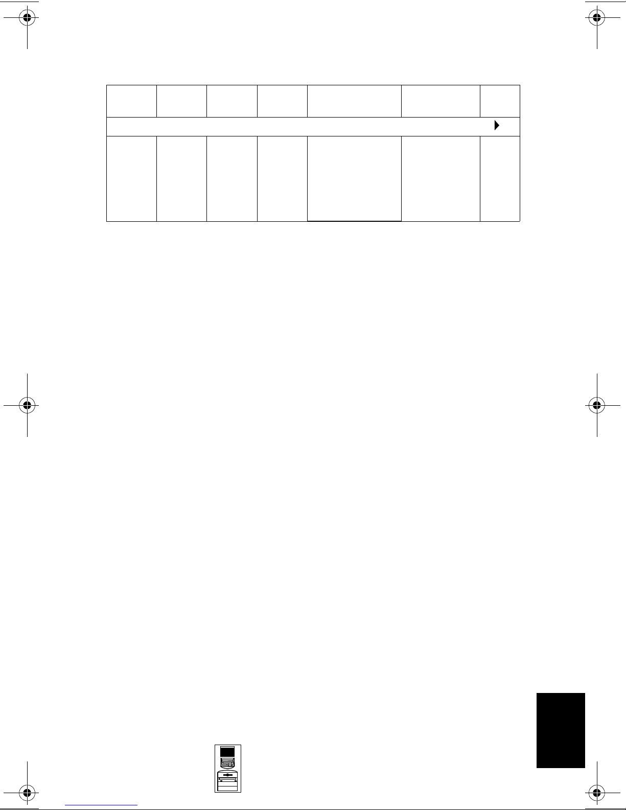
HP Kayak XA Minitower Series 05xx PC Workstations
Product
Number
HP Kayak XA Series 0503 PC Workstation 7/600 MHz 100 FSB (CPL: 08/99 )
D7993N
and
D7993T
1. FSB = Front Side Bus
2. Includes the HP 3-button mouse instead of the HP scrolling mouse which is included with
other bundles.
Cache
Memory
Pentium
III with
512 KB
of L2
cache
memory
Std.
RAM
128 MB
SDRAM
100 MHz
ECC
Hard
Drive
9.1 GB
7.2 krpm
SCSI
Video Controller Multi-media LAN
Matrox
Millennium G200
8 MB video
memory fitted.
Upgradable to
16 MB of memory.
32✕ Max IDE
CD-ROM.
Bolero add-on
audio board.
None
Mini-Tower
PC Workstations
10
HP Kayak XA Minitower Series 05xx PC
Workstations
10-3
Page 5

HP Kayak XA Minitower Series 05xx PC Workstations
Supported Accessories
Memory Upgrades
SDRAM 32MB 72bit 100MHz main memory unbuffered ECC) D6521A
SDRAM 64MB 72bit 100MHz main memory unbuffered ECC) D6522A
SDRAM 128MB 72bit 100MHz main memory (unbuffered ECC) D6523A
SDRAM 256MB 72bit 100MHz main memory (unbuffered ECC) D6743A
Processor Upgrades
Intel Pentium II Slot 1 Processor 400/512 KB D6528A
Intel Pentium II Slot 1 Processor 450/512 KB D6529A
Intel Pentium III 450 MHz containing 512 KB internal L2 cache D7510A
Intel Pentium III 500 MHz containing 512 KB internal L2 cache D7511A
Intel Pentium III 550 MHz containing 512 KB internal L2 cache D7512A
Intel Pentium III 600 MHz containing 512 KB internal L2 cache D7516A
Input Devices
HP keyboard for Windows® C4735A
HP standard 2-button mini-din mouse C3751B
HP mouse with scrolling wheel C4736A
Video Displays
All current HP PC Displays (refer to the Displays section of the Vectra
Accessory Service Handbook)
Mass Storage—Hard Disk Drives
4.3-GB 5400 rpm Ultra ATA/33 hard disk D2677A
6.4-GB 7200 rpm Ultra ATA/33 hard disk D6452A
10.1-GB 7200 rpm Ultra ATA/33 hard disk D6627A
9.1-GB 7200 rpm Ultra SCSI hard disk D6938A
Removable Mass Storage
32✕ Max-speed IDE CD-ROM drive D4384A
SureStore CD-Writer Plus 8100i internal CD-RW drive C4400A
SureStore Tape 5000i, 4 GB DAT drive C1526H
SureStore DAT 8i, 8 GB DAT drive C1528H
SureStore DAT 24i, 24 GB DAT drive C1555B
Atapi 100 MB Internal Iomega Zip Drive D6650A
10
10-4
HP Kayak XA Minitower Series 05xx PC
Workstations
Mini-Tower
PC Workstations
Page 6
HP Kayak XA Minitower Series 05xx PC Workstations
LAN Interfaces
HP NightDirector/Plus 10/100 Base-T Ethernet board
HP NightDirector/Plus 10/100 Base-T Ethernet board (bulk pack of 10) D6937A
Mounting Rails
5.25-inch CD-ROM side mounting rails, pack of 5 D2880A
3.5-inch floppy disk mounting rails, pack of 5 (for Desktop models only) D3566A
(x1) D6936A
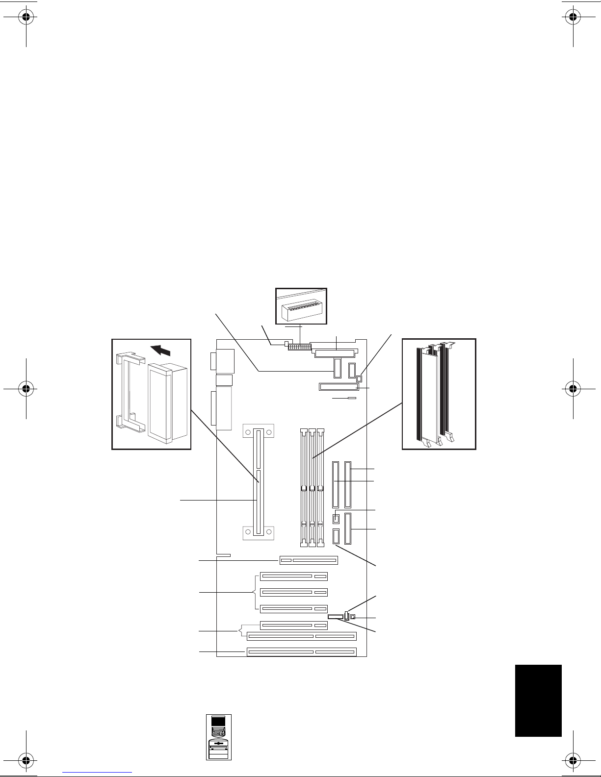
System Board, BIOS, and Memory
Switches
VRM 1
Minitower
LCD Status Panel
Processor
AGP Slot
PCI Slots
Processor
Fan
External Battery
Power
Minitower MaxiLife LCD
Status Panel
Fan Disk Drive
Floppy
Disk
Drive
Memory Modules
IDE 2 Connector
IDE 1 Connector
Buzzer
Not used on the Minitower
(Desktop MaxiLife and LCD
Status Panel)
Not used on the Minitower
(Desktop Audio Connector)
Wake On LAN
PCI/ISA Combination Slots
PCI Slot
Mini-Tower
PC Workstations
I/O Fan
External Start
10
HP Kayak XA Minitower Series 05xx PC
Workstations
10-5
Page 7
HP Kayak XA Minitower Series 05xx PC Workstations
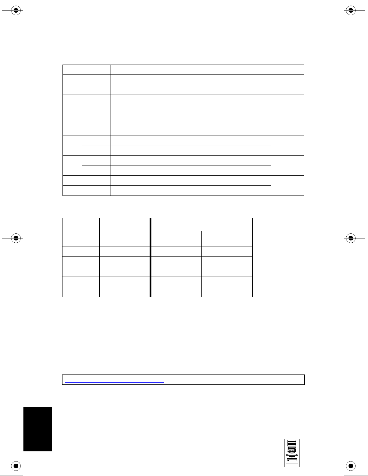
System Board Switches
Switch Function Default
1
1Up
2-5 - Processor frequency, see the following table -
Up Retains Configuration
6
Down Clears CMOS (to reload the Setup program defaults)
Up Enables passwords
7
Down Clears passwords
Up Disables keyboard power-on
8
Down Enables keyboard power-on (normal operation)
Up Minitower
9
Down Desktop
10 Up Enables BIOS normal mode
Down Enables BIOS recovery mode
1. Up=Off, Down=On.
Reserved Up
Up
Up
Down
Up
Up
Processor
Frequency
400 MHz 100 MHz Up
450 MHz 100 MHz Up
500 MHz 100 MHz Up
550 MHz 100 MHz Up
600 MHz 100 MHz Up
1. FSB = Front Side Bus
Local Bus
Frequency
(FSB)
1
Switch Switch
2345
Down Up Up
Down Up Down
Down Down Up
Down Down Up
Down Down Up
BIOS History
For the latest BIOS, the flasher utility program, and the BIOS history refer to the
HP World Wide Web site. The BIOS is in the form HU11yyzz
yy= BIOS version number
zz = is the selected language to be downloaded
http://www.hp.com/go/kayaksupport
10
10-6
HP Kayak XA Minitower Series 05xx PC
Workstations
Mini-Tower
PC Workstations
Page 8

HP Kayak XA Minitower Series 05xx PC Workstations
Upgrading the Processor
The PC Workstation has only one processor slot on the system board and is
supplied with either a Pentium II or Pentium II processor which includes an
integrated heatsink, level-1 and level-2 cache memory.
The processors are contained on a module which is installed in the processor
socket and is held in place by a bracket. To remove the processor, press the two
plastic clips towards each other and pull the processor out of its connector.
Cache Memory
512 KB of level-two cache memory is integrated in the Pentium II Slot 1
processor package.
Main Memory
The PC Workstation has three DIMM slots on the system board for installing
main memory; slots Mem 1, Mem 2 and Mem 3. Models are supplied with 64 MB
of non-ECC main memory. Memory upgrades are only available in single 32 MB,
64 MB, 128 MB or 256 MB unbuffered ECC SDRAM modules.
Memory can be upgraded to a maximum of 768 MB using multiples of
(3 x 256 MB) of unbuffered ECC memory modules.
A serial EEPROM on each DIMM contains data on the memory speed. This
information is read at each power on, and access time settings are set
accordingly.
Video Memory Upgrade
The graphics controller installed on the PC Workstation could be either an
ELSA GLoria Synergy™, a Matrox Millennium G200 or an Accel Galaxy AGP.
The Matrox Millennium G200 has a total of 8 MB of video memory already
supplied on the graphics controller board. Memory may be upgraded to a
maximum of 16 MB by installing a memory module of 8 MB onto the board. No
switch or jumper settings need to be changed.
The ELSA GLoria Synergy includes 4 MB of video SGRAM memory installed on
the graphics board. Added to this, there is a pre-installed 4 MB SO_DIMM video
memory module, giving a total of 8 MB (this is the maximum amount of video
memory possible).
The Accel Galaxy AGP Graphics card has 31 MB of video memory already
supplied on the graphics controller board, which cannot be further upgraded.
This card is supported only on the Windows NT operating system. Drivers do
not exist for Windows 95 nor Windows 98 operating systems.
Mini-Tower
PC Workstations
10
HP Kayak XA Minitower Series 05xx PC
Workstations
10-7
Page 9

HP Kayak XA Minitower Series 05xx PC Workstations
Parts and Part Numbers
10d
10c
4a
6
10a
1g
1f
3
5
15
1d
2a
2b
2c
1b
2
1
8
4b
2d
7
1e
1h
14
10
10-8
HP Kayak XA Minitower Series 05xx PC
Workstations
13
16
12a
17
12b
8
1c
10b
9
1a
10e
10
Mini-Tower
PC Workstations
Page 10

HP Kayak XA Minitower Series 05xx PC Workstations
Parts List
Item Description Repl.
Part Number
1 Chassis assembly:
a I/O Guide assembly
b Cover lock assembly
c Multimedia control panel
d 5.25-inch hard disk drive tray
e Hard Disk Drive Fan
f Processor airflow guide
g SCSI holder protection
h System board guide
Not shown:
I/O blank panel
Bumper foot
2 Cover Assembly
a Filler panel 3.5-inch
b Filler panel 5.25-inch
c Multimedia bezel
d LCD status panel kit
3 Processor retainer airflow guide
4 Logos
5065-0499
5064-6717
5062-5590
5064-6706
5002-1946
5064-6054
5064-3674
5042-3014
5042-1162
45935-00004
5042-2479
5064-3379
5042-1405
5042-1178
5042-1873
5064-6097
5042-3055 —
Exchange
Part Number
—
—
—
—
—
—
—
—
—
—
—
—
—
—
—
a Hewlett-Packard logo
b XA PC Workstation logo
5 Ultra ATA hard disk drive (standard)
4.3 GB IDE 5400 rpm D2677-63001 D2677-69001
6.4 GB IDE 7200 rpm
10.1 GB IDE 7200 rpm D6627-63001 D6627-69001
9.1 GB UW-SCSI 7.2k rpm (Low Profile)
6 Power supply unit - 200W 0950-2893 —
7 Standard 32X IDE CD-ROM drive
8 HDD 5.25-inch Rail kit + 3.5-inch rail
9 ATA/IDE cable kit
Cables:
10
a CD-ROM to audio cable
b Floppy disk drive cable
c SCSI cable (16-bit data) for SCSI
models only
d LAN-to-CPU internal cable (3COM)
e External Start cable
Headset (supported only on models
11
shipped before November, 1998)
1
5042-3030
5042-3066
D6452-63101 D6452-69001
D6455-63101 D6455-69001
D4384-63031 D4384-69031
5063-7922 —
5064-6702 —
5182-1857
5183-0746
5183-2192
5183-2769
5183-6090
5064-2673 —
—
—
—
—
—
—
—
Mini-Tower
PC Workstations
10
HP Kayak XA Minitower Series 05xx PC
Workstations
10-9
Page 11

HP Kayak XA Minitower Series 05xx PC Workstations
Parts List
Item Description Repl.
Part Number
12 Graphics Board
a Matrox Millennium G200
b ELSA Synergy 8 MB Video Board
Not shown:
Accel Galaxy 31MB
13 2-button mouse with scrolling wheel
Not shown:
HP 3-button mouse (only shipped with
models with the Accel Galaxy video board)
14 System board
15 Floppy disk drive (bezel-less) 3.5-inch
16 Bolero Audio board
LAN cards:
17
SCSI/100TX LAN Combo board
Not shown:
HP LAN board
3 COM LAN board
Not
Shown
Enhanced Keyboard (US and European)
Power cable European 220V
Screw 6-32 auto-guiding (long)
Screw 6-32 for card cage and chassis 2360-0565 —
5064-7478
5064-6732
5064-9190
C4736-60101
C4728-60101
See PC’s system board parts list
D2035-60191 —
5064-2620 —
5064-6016
5067-6057
5064-3672
C4734-60301 —
8120-1689 —
2680-0311 —
Exchange
Part Number
D5685-69501
D6478-69501
D6728-69501
—
—
D6331-69301
—
—
10
1. For optional disk drive information, refer to the Accessories section of this Service
Handbook.
10-10
HP Kayak XA Minitower Series 05xx PC
Workstations
Mini-Tower
PC Workstations
Page 12

HP Kayak XA Minitower Series 05xx PC Workstations
System Board Parts List
Description Repl.
Part Number
System board:
XA 6/xxx Series 05xx system board D6720-63001 D6720-69001
Processors:
Intel Pentium II 350/512 D6527-63101 D6527-69101
Intel Pentium II 400/512 D6528-63101 D6528-69101
Intel Pentium II 450/512 D6529-63001 D6529-69101
Intel Pentium III 450 MHz, 512 KB cache D7510-63001 —
Intel Pentium III 500 MHz, 512 KB cache D7511-63001 —
Intel Pentium III 550 MHz, 512 KB cache D7512-63001 —
Intel Pentium III 600 MHz, 512 KB cache D7516-63001 —
Main memory modules:
SDRAM 32MB 100MHz non-ECC D6501-69001 —
SDRAM 64MB 100MHz non-ECC D6502-69001 —
SDRAM 64MB 100MHz ECC D6522-69001 —
SDRAM 128MB 100MHz ECC D6523-69001 —
SDRAM 256MB 100MHz ECC D6524-69001 —
Exchange
Part Number
Manuals and Documentation
Description Part Number
User’s Guide - English only
(refer to page 10-4 for all multilingual
manual part numbers)
Familiarization Guide D6739-90901 Electronic file
Technical Reference Manual no number Electronic file
ConfigTailor CD-ROM 5011-6634 —
D6739-90001 Paper document
(PDF)
(PDF)
Mini-Tower
PC Workstations
10
HP Kayak XA Minitower Series 05xx PC
Workstations
10-11
Page 13

HP Kayak XA Minitower Series 05xx PC Workstations
Notes: _____________________________________________________________
____________________________________________________________________
____________________________________________________________________
____________________________________________________________________
____________________________________________________________________
____________________________________________________________________
____________________________________________________________________
____________________________________________________________________
____________________________________________________________________
____________________________________________________________________
____________________________________________________________________
____________________________________________________________________
____________________________________________________________________
____________________________________________________________________
____________________________________________________________________
____________________________________________________________________
____________________________________________________________________
____________________________________________________________________
10
10-12
HP Kayak XA Minitower Series 05xx PC
Workstations
Mini-Tower
PC Workstations
Page 14

A
Beep, POST, and Error Codes
Beep Codes
If an error occurs during the POST, which prevents the PC Workstation from
starting, and before the display device has been initialized, a series of beep
codes are issued. Beep codes indicate that a fatal error has occurred and can be
reported one after another if there is more than one detected error. In this case,
the first detected error is the most important.
These codes are useful for identifying the error when the system is unable to
display the error message.
A
Beep, POST, and Error Codes A-1
Page 15

A
Beep Codes for the HP Kayak XU800
Number
of
Beeps
1 The memory refresh
2 Parity error in the base
3 Memory error.
4 Clock error. • Check that the system board is correctly
5 Processor test error. Check that:
Description Action to Take...
Check that:
circuitry is faulty.
memory (the first 64 KB
block) of memory.
• Memory is installed correctly.
• Correct memory modules are being used.
If the error still occurs, replace the memory.
cabled (power cables, processor and
terminator).
If the error still occurs, replace the system
board.
• Processor is correctly installed.
• Termination card installed in processor
slot 2 in a single processor system.
If the error still occurs, replace:
1Processor.
2 system board.
6 Input/Output (I/O) error. • Keyboard is connected.
• PCI card is installed correctly.
• Termination card installed in processor
slot 2 in a single processor system.
7 The processor on the
system board generated
an error.
8 The system video card is
either missing or faulty.
• There is an installed processor(s).
• Processor(s) is correctly installed in the
processor slot(s).
• Two installed processors have the same
cache size (256 k).
• Termination card is installed in processor
slot 2 in a single processor system.
• VRM is installed in the VRM socket in a
dual processor system.
If the error still occurs, replace the system
board.
This is not a fatal error. Check that the video
card is correctly installed and cabled. If
missing, install the video card. If the error
still occurs, replace it with a known working
video card.
A-2 Beep, POST, and Error Codes
Page 16

A
Number
of
Beeps
9 The BIOS Checksum
10 The CMOS RAM has
11 The cache memory test
Description Action to Take...
value does not match the
value encoded in the
BIOS.
failed.
failed.
Perform the following actions in this order:
1Press F2 to enter the Setup program,
then F9 to load the default BIOS settings.
2 Clear the CMOS.
3 Flash the BIOS.
If the error still occurs, replace the system
board.
Perform the following actions in this order:
1Press F2 to enter the Setup program,
then F9 to load the default BIOS settings.
2 Clear the CMOS.
3 Flash the BIOS.
If the error still occurs, replace the system
board.
Replace the processor(s).
Beep, POST, and Error Codes A-3
Page 17

A
Beep Codes for the HP Kayak XM600
Beep
Pattern
— - - - - - - -
— - - - — —
— - - - — - - -
— - - - - - - —
— - - - - - - - —
— - - - - - - - - - -
— - - - - — —
- - — - - - - -
- - - - - - - —
Beep
Code
1-2-2-3 16h
1-3-1-1 20h
1-3-1-3 22h
1-3-3-1 28h
1-3-4-1 2Ch
1-3-4-3 2Eh
1-4-1-1 30h
2-1-2-3 46h
2-2-3-1 58h
Numeric
Code
Description Recommended
Action
BIOS ROM
check-sum
failure
DRAM refresh
test failure1
8042
Keyboard
controller test
failure
Initialization
of RDRAM
has failed.
RAM failure
on address
1
....
line
RAM failure
on data bits
....of low byte
of memory
bus1
RAM failure
on data bits
....of high byte
of memory
bus1
ROM
copyright
notice check
failure
Unexpected
interrupts test
failure
Inform HP support/HP reseller
that system board is defective.
Check the memory is correctly
installed. If the error still occurs,
replace the module.
Inform HP support/HP reseller
that system board is defective.
Verify that memory or continuity
modules are installed.
Check the memory is correctly
installed. If the error still occurs,
replace the module.
Check the memory is correctly
installed. If the error still occurs,
replace the module.
Check the memory is correctly
installed. If the error still occurs,
replace the module.
Inform HP support/HP reseller
that system board is defective.
Inform HP support/HP reseller
that system board is defective.
— - -
1. Non-HP memory modules are not supported. Only HP memory modules should be used.
1-2 98h
A-4 Beep, POST, and Error Codes
Video
configuration
failure or
option ROMs
check-sum
failure
This can be caused by problems
with the ROM on integrated
video, an add-on video board or
the ROM on a SCSI card.
Inform reseller for the affected
component.
Page 18

POST and Error Codes
Beep Codes for Previous Models
The following beep codes are for all models before the HP Kayak XU800 and
XM600 PC Workstations.
A
Beep Pattern Beep
Code
— - - - - - - - 1-2-2-3 16h BIOS ROM check-sum failure
— - - - — — 1-3-1-1 20h DRAM refresh test failure
— - - - — - - - 1-3-1-3 22h 8742 Keyboard controller test failure
1-3-3-1 28h Autosize DRAM
1-4-4-1 30h RAM failure on data bits of high byte of
— - - - - - - - — 1-3-4-1 2Ch RAM failure on address line xxxx
— - - - - - - - - - - 1-3-4-3 2Eh RAM failure on data bits xxxx1 of low
- - — - - - - - 2-1-2-3 46h ROM copyright notice check failure
- - - - - - - — 2-2-3-1 58h Unexpected interrupts test failure
— - - 1-2 98h Video configuration failure or option
- 1 B4h /
- - - - - - - - - - - - - - - 4-2-4-4 Crisis recovery flash error
Numeric
Code
F4h
Description
memory bus
1
byte of memory bus
ROMs check-sum failure
This does not indicate an error. There is
one short beep before system startup.
2
1. If the BIOS detects error 2C or 2E (base 512K RAM error), it displays an additional wordbitmap (xxxx) indicating the address line or bits that failed. For example, “2C 0002” means
address line 1 (bit one set) has failed. “2E 1020” means data bits 12 and 5 (bits 12 and 5 set)
have failed in the lower 16 bits.
2. For more information, refer to Appendix B.
POST and Error Codes
A list of all POST (Power-On Self-Test) and error codes are available through
electronic files from the Support Center.
If you wish to view the POST details, press the key when the Kayak logo is
being displayed at power on, and the checkpoint code of the test currently in
progress will appear in the upper right corner of the screen. When POST is
completed, the HP Summary Screen will appear.
Beep, POST, and Error Codes A-5
Page 19

A
POST and Error Codes
Notes: ______________________________________________________________
____________________________________________________________________
____________________________________________________________________
____________________________________________________________________
____________________________________________________________________
____________________________________________________________________
____________________________________________________________________
____________________________________________________________________
____________________________________________________________________
____________________________________________________________________
____________________________________________________________________
____________________________________________________________________
____________________________________________________________________
____________________________________________________________________
A-6 Beep, POST, and Error Codes
Page 20

B
Recovery Boot Active Procedures
HP Kayak XU800 PC Workstation
BIOS Recovery
NOTE: The following BIOS recovery (Crisis Mode) is for the HP
Kayak XU800 PC Workstation models only.
If for some reason the BIOS is corrupted and the standard flash cannot be used,
use the BIOS Recovery Mode (exceptional BIOS recovery operation) to restore
the BIOS.
The following recovery operation is also documented in the flash.txt file which
is supplied with the downloaded BIOS files.
To restore the BIOS:
1 Copy the BIOS files on to the floppy disk.
B
2 Rename the file AI11xx.rom to amiboot.rom.
3 Shut down the PC Workstation.
4 Power off the PC Workstation and remove the power cord and cables.
5 Remove the cover.
6 Set switch 1 to the DOWN position.
7 Insert the floppy disk into the floppy disk drive.
8 Reconnect the power cord and switch on the PC Workstation.
9 The PC Workstation boots from the floppy disk, then flashes the BIOS.
However, it should be noted that during the flash process, the screen remains
blank. MaxiLife will display a message on the LCD panel “RECOVERY
MODE”.
10 The recovery process is finished when there are four beeps.
11 Power off the PC Workstation. Remove the floppy disk from the drive.
Remove the power cord.
12 Set switch 1 back to the UP position.
13 Replace the cover, reconnect the power cord, then reboot the PC
Workstation.
Recovery Boot Active Procedures B-1
Page 21

HP Kayak XM600 PC Workstation Desktop and
Minitower BIOS Recovery
B
NOTE: The following BIOS recovery (Crisis Mode) is for the HP
Kayak XM600 Desktop and Minitower PC Workstations
only.
If for some reason the BIOS is corrupted and the standard flash cannot be used,
use the BIOS Recovery Mode (exceptional BIOS recovery operation) to restore
the BIOS. To do this:
1 Obtain a bootable DOS floppy disk.
2 Copy the BIOS files on to the floppy disk.
The latest system BIOS (standard flash operation) can be downloaded from
HP’s Support Web site at: http://www.hp.com/go/kayaksupport. Then select
HP Kayak XM600 PC Workstation.
Instructions on updating the BIOS are supplied with the downloaded BIOS
files and a BIOS flash utility (flash.txt).
3 Create (or edit) the file, AUTOEXEC.BAT This should contain a single line of
text: “phlash /c /mode=3 IC1105US.FUL”
(rename the BIOS filename with the one on the floppy disk).
4 Shut down the PC Workstation.
5 Power off the PC Workstation and remove the power cord.
6 Remove the cover.
7 Set switch 7 to the ON position.
8 Insert the floppy disk into the floppy disk drive.
9 Reconnect the power cord and switch on the PC Workstation.
10 The PC Workstation boots from the floppy disk, then flashes the BIOS.
However, it should be noted, that during the flash process, the screen
remains blank.
11 The recovery process is finished when there is one very long beep.
12 Power off the PC Workstation. Remove the floppy disk from the drive.
Remove the power cord.
13 Set switch 7 back to the OFF position.
14 Replace the cover, reconnect the power cord, then reboot the PC
Workstation.
B-2 Recovery Boot Active Procedures
Page 22

Force BIOS flash, Switch 9 (XA models) or
10 (XW and XA-s models) Down Position
WARNING: WARNING: For Kayak XU Series 03xx, XA-s Series
02xx and XA Series 05xx, a specific ‘Mini-Dos’
bootable disk has to be used. An image of this
‘Mini-Dos’ bootable floppy can be obtained from
the Alps/Info server (not available from the
external web site). If you do not have access to the
Alps/Info server, contact your escalation team.
If, for example, during a BIOS flash, the procedure is interrupted by a power
failure, and the system does not restart, then you can force a BIOS flash.
However, it should be noted that during the procedure, there is no image on the
screen, nor access to the keyboard or mouse (only “vital” devices that are
required to boot on the floppy device are initialized).
To force a BIOS flash, do the following steps:
1 Ensure that you have created a DOS-bootable diskette. This floppy diskette
contains all the recovery and system BIOS programming software
(phlash.exe, platform.bin and hb1xxxyy.Ful). Include the flash command in
the autoexec.bat, for example: phlash /mode=3 hb1xxxyy.Ful
2 Turn off the computer.
B
3 Set Switch 9 (XA models) or,
Set Switch 10 (XW, XU and XA-s models) to the DOWN position (=on).
4 Insert the DOS-bootable diskette (refer to the above warning).
5 Power on the computer.
6 During the recovery process, short beeps are emitted. The recovery process
is finished when there is a much longer beep (approximately around 1 to 2
minutes).
7 Power off the computer. Press the power ON/OFF button (for about 5
seconds), until the ON/OFF light switches off. Set the switch 10 to the UP
position (=off).
Recovery Boot Active Procedures B-3
Page 23

B
Notes: ______________________________________________________________
____________________________________________________________________
____________________________________________________________________
____________________________________________________________________
____________________________________________________________________
____________________________________________________________________
____________________________________________________________________
____________________________________________________________________
____________________________________________________________________
____________________________________________________________________
____________________________________________________________________
____________________________________________________________________
____________________________________________________________________
____________________________________________________________________
B-4 Recovery Boot Active Procedures
 Loading...