

Page 1
Installation Manual
Model D640
HP 5000
Cut Sheet
Printers
(Printer and Accessories)
Page 2

HP 5000
D640 Cut Sheet Printer
Installation Manual
(for Printer and Accessories)
Hewlett-Packard Company
HP Part No. C5620-90015
E1196
Page 3

Notice
The contents of this manual may be revised without prior notice and without obligation to
incorporate changes and improvements into units already shipped.
Every effort has been made to ensure that the information included here is complete and
accurate at the time of publication. However, Hewlett-Packard cannot be held r esponsible
for errors and omissions.
Copyright ©1996 Hewlett-Packard
Printed in USA. All rights reserved. No part of this manual may be repr oduced or trans-
lated, stored in database or retrieval system, or transmitted, in any form or by any means,
electronic, mechanical, photocopying, recording, or otherwise, without the prior written
permission of Hewlett-Packard.
Trademarks
Hewlett-Packard Corporation: PCL, HP-GL/2, Bi-Tronics
Adobe Systems, Inc: PostScript
Centronics Data Comput er Cor por ati o n: Cent ron ic s
Apple Computer, Inc.: Apple Talk, Local Talk
Novel, Inc.: Netware
Other product names mentioned in this manual may also be trademarks and are used here
for identification only.
Printing History
The dates on the title page change only when a new edition is published.
Edition 1.1....................November 1996
ii
Page 4

Caution and Warning Notes
The CAUTION note denotes a hazard. It calls attention to a procedure which, if done
incorrectly or inatten tivel y, co ul d d amage o r des troy part or all of the produ ct. Do n ot pr oceed beyond a CAUTION note until the indicated conditions are fully understoo d and met.
The WARNING note denotes a hazard. It calls attention to a procedure, practice, or the
like, which, if not done correctly or adhered to, could result in injury. Do not proceed
beyond a WARNING sign until the indicated conditio ns are fully understood and met.
The following conventions are used throughout this manual:
NOTE:
CAUTION:
WARNING:
Notes contain important information set off from the text.
Caution messages indicate procedures which, if not observed, could
result in damage to equipment.
Warning messages call attention to situations that could result in
personal injury.
iii
Page 5

WARNING:
Disconnect the printer from its power source whenever performing
any maintenance or installation procedure.
WARNING:
WARNING:
WARNING:
Please address any comments or questions with respect to this document to:
Hewlett-Packard Company
HP 5000 Printers - MS 44MC
System Peripherals Operation
19111 Pruneridge Ave.
Cupertino, California 95014-9804
The printer is equipped with safety interlock switches on most of its
covers. The switches disable parts of the printer when the covers are
opened. These areas present the ri sk of electric shock, burns, and
injury from mechanical hazards.
Any unauthorized removal of safety covers, manipulation of safety
switches, and interference with the safety system is strictly
prohibited. Such actions can cause personal injury and can damage
the system. Also make sure that the operating and maintenance
areas are not obstructed in any way.
With any drive mechanism, loosely hanging items of clothing and
jewelry, such as ties, belt ends, neck lace s, br ace lets, a nd rings, and
unprotected hair can cause injury if caught in the mechanism.
iv
Page 6

Preface
The Installation Manual contains all the information needed to install and set up the
HP 5000 model D640 printer and it’s accessories.
The information within is directed toward printer users who are familiar with printer con-
figuration operations and are comfortable performing basic mechanical operations.
Other Manuals
The HP 5000 D640 User Manual, contains all the information needed to operate
Hewlett-Packard D640 printers.
The HP 5000 D640 Service Manual, C5620-90013, is a comprehensive technical refer-
ence to all mechanical and electronic components in the printer. Th e Ser vice Manu al helps
you perform fault diagnosis and isolation, then guides you through replacement of subassemblies.
The
HP 5000 D640 Technical Reference Manual,
about software conventions and hardware components not covered in the User, Service, or
Installation Manuals.
The HP 5000 D640 Paper Specifications Guide, C5620-90001, explains the var ious kind s
of papers usable in the printer, how to care for them, and how to minimize paper-related
problems with the D640.
C5620-90002, provides information
v
Page 7

Table of Contents
Chapter 1 Introduction
Introduction . . . . . . . . . . . . . . . . . . . . . . . . . . . . . . . . . . . . . . . . . . . . . . . . . . . . 1-3
Chapter 2 Installation
Site Preparation . . . . . . . . . . . . . . . . . . . . . . . . . . . . . . . . . . . . . . . . . . . . . . . . . 2-3
The Installation Process . . . . . . . . . . . . . . . . . . . . . . . . . . . . . . . . . . . . . . . . . . . 2-6
Procedure 1: Identifying the Printer Installation Boxes . . . . . . . . . . . . . . . . . . 2-7
Procedure 2: Opening the Starter Kit . . . . . . . . . . . . . . . . . . . . . . . . . . . . . . . . 2-9
Procedure 3: Unpacking the Printer . . . . . . . . . . . . . . . . . . . . . . . . . . . . . . . . 2-12
Procedure 4: Getting To Know Your Printer . . . . . . . . . . . . . . . . . . . . . . . . . 2-21
Procedure 5: Inside the Front Door. . . . . . . . . . . . . . . . . . . . . . . . . . . . . . . . . 2-25
Procedure 6: Installing Ozone Filter and Manual Pocket . . . . . . . . . . . . . . . . 2-39
Procedure 7: Removing Paper Tray Packing Material . . . . . . . . . . . . . . . . . . 2-41
Procedure 8: Powering On the Printer. . . . . . . . . . . . . . . . . . . . . . . . . . . . . . . 2-43
Procedure 9: Adding New Supplies . . . . . . . . . . . . . . . . . . . . . . . . . . . . . . . . 2-47
Procedure 10: Setting the Paper Trays . . . . . . . . . . . . . . . . . . . . . . . . . . . . . . . 2-60
Procedure 11: Installing Function Code. . . . . . . . . . . . . . . . . . . . . . . . . . . . . . 2-71
Procedure 12: Setting the Date and Time. . . . . . . . . . . . . . . . . . . . . . . . . . . . . 2-76
Procedure 13: Printing a Setup Report. . . . . . . . . . . . . . . . . . . . . . . . . . . . . . . 2-79
Troubleshooting . . . . . . . . . . . . . . . . . . . . . . . . . . . . . . . . . . . . . . . . . . . . . . . . 2-81
Procedure 14: Securing the Printer. . . . . . . . . . . . . . . . . . . . . . . . . . . . . . . . . . 2-82
Procedure 15: Paper Path Alignment . . . . . . . . . . . . . . . . . . . . . . . . . . . . . . . . 2-83
vii
Page 8

Chapter 3 Host Computer Interface
Installation and Configuration
Printer Interfaces. . . . . . . . . . . . . . . . . . . . . . . . . . . . . . . . . . . . . . . . . . . . . . . . .3-3
Procedure 1: Install the Interface Cable . . . . . . . . . . . . . . . . . . . . . . . . . . . . . .3-10
Procedure 2: Configure the Printer on Your Host System . . . . . . . . . . . . . . . .3-11
Procedure 3: Setting the Printer’s Communication Interface . . . . . . . . . . . . .3-21
Procedure 4: Confirm the Connection . . . . . . . . . . . . . . . . . . . . . . . . . . . . . . .3-26
Interface Troubleshooting. . . . . . . . . . . . . . . . . . . . . . . . . . . . . . . . . . . . . . . . .3-27
Chapter 4 Accessories
Accessories . . . . . . . . . . . . . . . . . . . . . . . . . . . . . . . . . . . . . . . . . . . . . . . . . . . . .4-3
Procedure 1: High-Capacity Input (HCI) Installation. . . . . . . . . . . . . . . . . . . . .4-4
Procedure 2: High-Capacity Output (HCO) Installation . . . . . . . . . . . . . . . . .4-16
Procedure 3: Installing Memory . . . . . . . . . . . . . . . . . . . . . . . . . . . . . . . . . . .4-34
Procedure 4: Installing PostScript . . . . . . . . . . . . . . . . . . . . . . . . . . . . . . . . . .4-42
Procedure 5: Custom Tray Installation . . . . . . . . . . . . . . . . . . . . . . . . . . . . . . .4-46
Appendix A Packing and Shipping
Packing and Shipping the Printer . . . . . . . . . . . . . . . . . . . . . . . . . . . . . . . . . . . A-3
Appendix B Warranty and Support
Where To Call For Help . . . . . . . . . . . . . . . . . . . . . . . . . . . . . . . . . . . . . . . . . . B-3
Warranty . . . . . . . . . . . . . . . . . . . . . . . . . . . . . . . . . . . . . . . . . . . . . . . . . . . . . . B-6
viii
Page 9

Chapter 1 Introduction
Chapter 1
Introduction
Introduction
Introduction 1-1
Page 10

Introduction
Thank you for purchasing the D640 printer.
Introduction
This installation manual is written in a logical, step by step format for quick and easy
installation of the D640 printer and all available accessories. A typical installation will
take about 1 to 2 hours to complete. We strongly encourage you to follow the procedures
in the order they are presented to avoid missing any critical steps. If you run into any questions or problems during the installation, you can call Hewlett-Packard and receive immediate assistance. See Warranty and Support for support telephone numbers.
You may need the following tools to complete the installation:
• Cutter to remove packaging straps
• Pliers to remove shipping lock inserts
• #2 Phillips head screwdriver (to install HCI, HCO, and/or Memory).
• Medium flat blade screwdriver (to install HCO).
The installation manual is organized as these chapters:
Chapter 2, Installation:
This chapter is broken down into a number of procedures that covers every step of the
unpacking and installation process for the basic printer.
Chapter 3, Host Computer Interface Installation and Configuration:
This chapter covers the basic information needed to connect the printer to a h ost computer.
Chapter 4, Accessories:
This chapter covers all the details for unpacking and installing each of the available acces-
sory products used with the printer.
Introduction
Appendix A, Packing and Shipping:
This chapter shows you the required steps to repackage your printer in case it needs to be
shipped to another location.
Appendix B, Warranty and Support:
This chapter provides a list of phone number where you can call for free assistance during
the installation process, and a list of telephone nu mbe rs to call if there are problems with
the printer hardware.
Introduction 1-3
Page 11

Chapter 2 Installation
Chapter 2
Installation
Installation
Installation 2-1
Page 12

Site Preparation
Site Preparation
This chapter provides step-by-step instructions for installing your printer.
You may have purchased one of the following D640 accessories:
• PostScript
• Additional memory
• Custom tray
• High-Capacity Input (HCI)
• High-Capacity Output (HCO)
Install them only after you have completely installed and successfully te sted the printer.
Instructions for installing these accessories appear in Chapter 4, Accessories.
Before you begin, make sure the location you have selected for your printer meets the
space and environmental requirements, as shown in Table 2-1.
Table 2-1 Printer Environment Specifications
Power Requirements 120-127 or 200-240 Vac ±10%, 50/60Hz, 12 or 7A.
Physical Dimensions
(without HCI/HCO)
Length:
Depth:
Height:
Physical Dimensions
(with HCI/HCO)
Length:
Depth:
Height:
Weight 298lbs (135kg)
Temperature Operating: 59° F to 95°F (15° – 35°C)
Relative humidity 40%–60% (optimal)
23.0in (585mm)
25.2in (640mm)
40.6in (1,030mm)
55.7in (1414mm)
25.2in (640mm)
40.6in (1030mm)
Installation
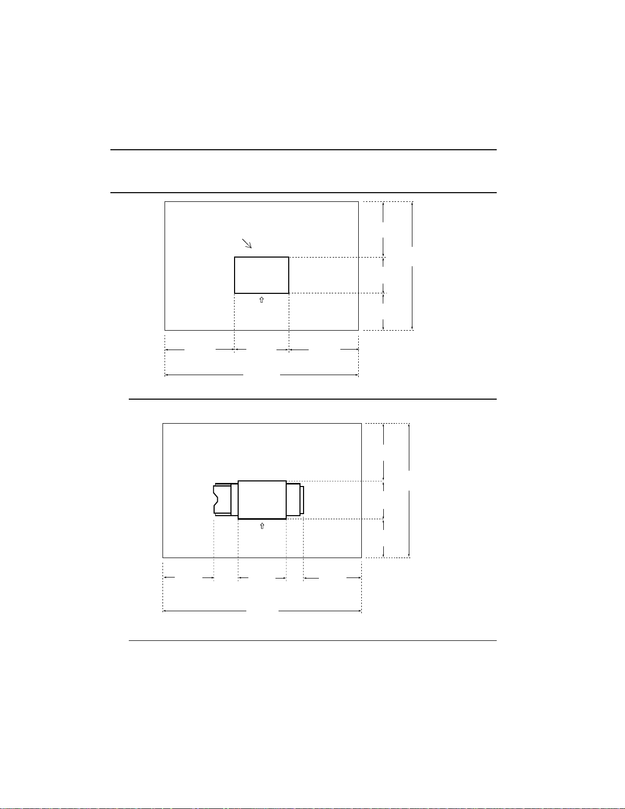
Refer to the following illustrations for help in situating th e printer. Remember to leave
adequate space for opening the front and side covers, and for air circulation to the ventilation openings on the rear of the printer. If you have purchased the HCI or HCO, you need
to reserve space for them as well.
Installation 2-3
Page 13
Site Preparation
CAUTION: Provide for adequate ventilation when selecting your site. To ensure
reliable operation, do not block the ventilation slots and openings on
the exterior of the printer.
Ventilation slots
Operating
33.5 in.
(850 mm)
(585 mm)
(2285 mm)
Printer
Side
23.0 in.
90.0 in.
33.5 in.
(850 mm)
33.5 in.
(850 mm)
25.2 in.
(640 mm)
25.6 in.
(650 mm)
Figure 2-1 Operating Area Space Without HCI or HCO
33.5 in.
(850 mm)
Printer HCIHCO
25.2 in.
(640 mm)
84.3 in.
(2140 mm)
84.3 in.
(2140 mm)
Operating
Side
33.5 in.
(850 mm)
21.25 in.
(540 mm)
23.0 in.
(585 mm)
122.6 in.
(3114 mm)
11.4 in.
(289 mm)
33.5 in.
(850 mm)
Figure 2-2 Operating Area Space With HCI and HCO
2-4 Installation
25.6 in.
(650 mm)
Page 14
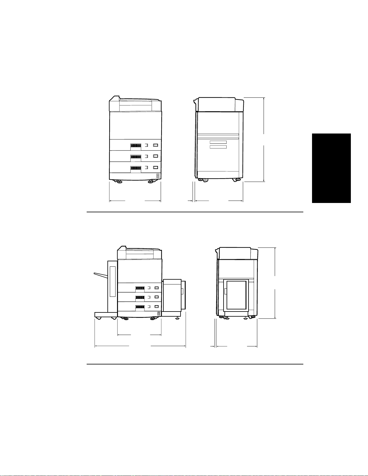
Site Preparation
40.5 in.
LTR
LTR
LTR
1030 mm
Installation
23.0 in.
585 mm
1.4 in.
35 mm
25.2 in.
640 mm
Figure 2-3 Physical Dimensions (Front and Right Side View)
Without HCI or HCO
LTR
LTR
LTR
23.0 in.
(585 mm)
55.66 in.
(1413.7 mm)
1.4 in.
(35 mm)
Figure 2-4 Physical Dimensions (Front and Right Side View)
With HCI and HCO
25.2 in.
(640 mm)
40.5 in.
(1030 mm)
Installation 2-5
Page 15

The Installat ion Process
The Installation Process
The installation process is broken down into a number of key procedures, each of which
contains several different activities concentrated in a particular physical location of the
printer. The procedures covered in this chapter include:
• Procedure 1: Identifying the Printer Installation Boxes, on page 2-7
• Procedure 2: Opening the Starter Kit, on page 2-9
• Procedure 3: Unpacking the Printer, on page 2-12
• Procedure 4: Getting To Know Your Printer, on page 2-21
• Procedure 5: Inside the Front Door, on page 2-25
• Procedure 6: Installing Ozone Filter and Manual Pocket, on page 2-39
• Procedure 7: Removing Paper Tray Packing Material, on page 2-41
• Procedure 8: Powering On the Printer, on page 2-43
• Procedure 9: Adding New Supplies, on page 2-47
• Procedure 10: Setting the Paper Trays, on page 2-60
• Procedure 11: Installing Function Code, on page 2-71
• Procedure 12: Setting the Date and Time, on page 2-76
• Procedure 13: Printing a Setup Report, on page 2-79
• Procedure 14: Securing the Pri nte r, on page 2-82
• Procedure 15: Paper Path Alignment, on page 2-83
Once you have completed these procedures, the printer will be up and running as a standalone unit.
Save packing materials for repacking later, if necessary.
Required Tools
You will need the following additi onal tools for installation:
• Pliers to remove plastic lock inserts.
• Cutter to remove plastic strapping material.
• #2 Phillips screwdriver (if you are installing Memory, HCI or HCO).
• Medium flat blade screwdriver (if you are installing an HCO).
NOTE: Move the printer close to its final loc ation before unpacking. M ake sure
you have room to lower the ramp before moving the printer off of the
pallet.
2-6 Installation
Page 16
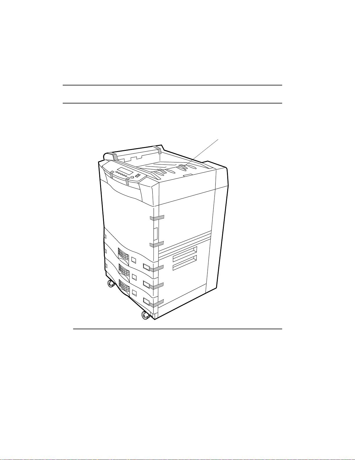
Procedure 1: Identifying the Printer Installation Boxes
Procedure 1: Identifying the Printer Installation Boxes
There are at least two boxes comprising the printer installation; two more if yo u have purchased the High Capacity Input (HCI) and High Capacity Output (HCO). The printer and
starter kit boxes are illustrated in Figure 2-5.
STARTER KIT
Unpacking
instructions
PRINTER
Installation
Figure 2-5 Printer Boxes
Installation 2-7
Page 17
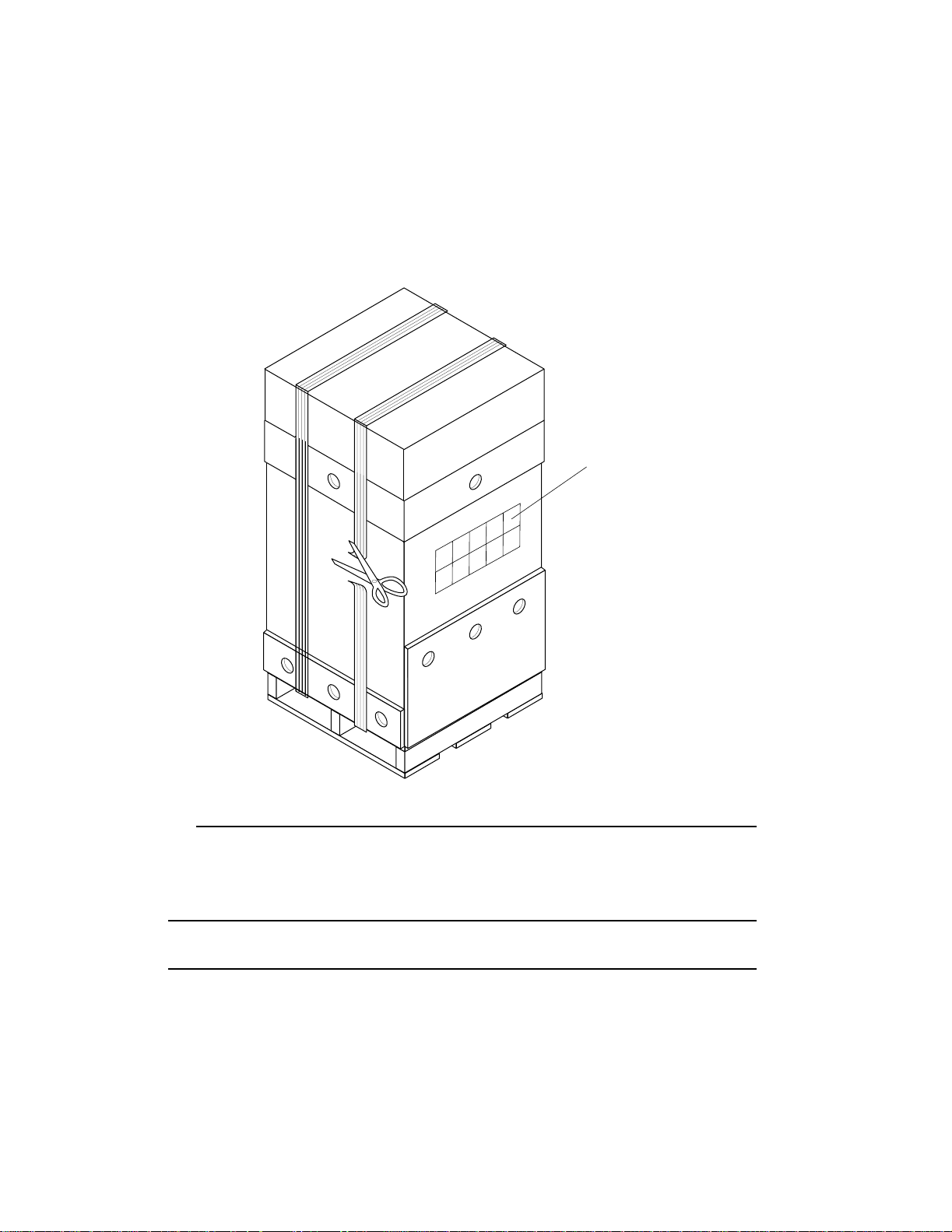
Procedure 1: Identify ing the Printer Installation Boxes
1. Cut the plastic strap as shown in Figure 2-6.
STARTER KIT
Figure 2-6 Cutting Plastic Strap
2. Remove Starter Kit box from the top of the printer.
3. Proceed to Procedure 2: Opening the Starter Kit.
Unpacking
instructions
NOTE: If you purchased any accessories, do not open them at this time, they will
be installed later.
2-8 Installation
Page 18
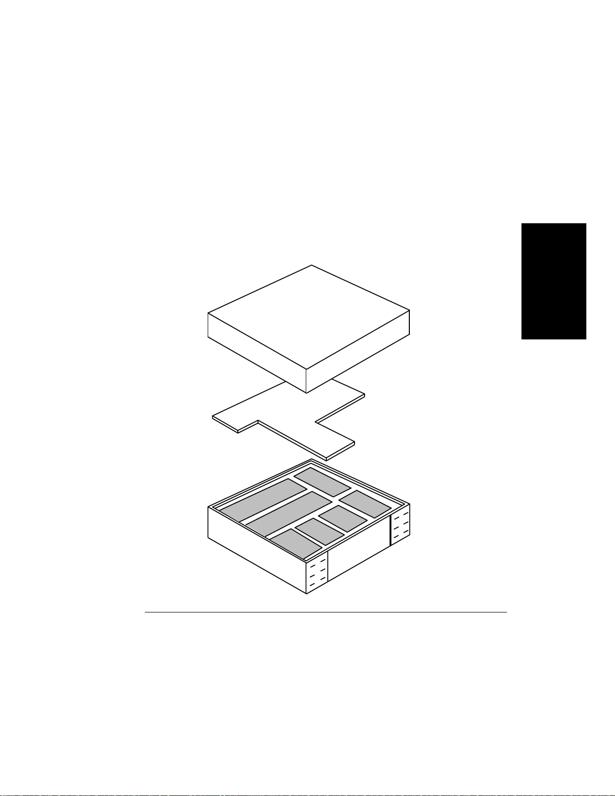
Procedure 2: Opening the Starter Kit
Procedure 2: Opening the Starter Kit
Open the package identified as Starter Kit shown in Figure 2-5, Printer Boxes, on page
2-7, and examine the cont ents, shown i n Figure 2-8 , on page 2-10. The Start er Kit cont ains
the supplies necessary to set up the printer for immediate use (see Figure 2-8). Check the
contents of the starter kit box to make sure you have all of the comp onents listed in
Table 2-2.
Installation
Figure 2-7 Starter Kit Box
Installation 2-9
Page 19
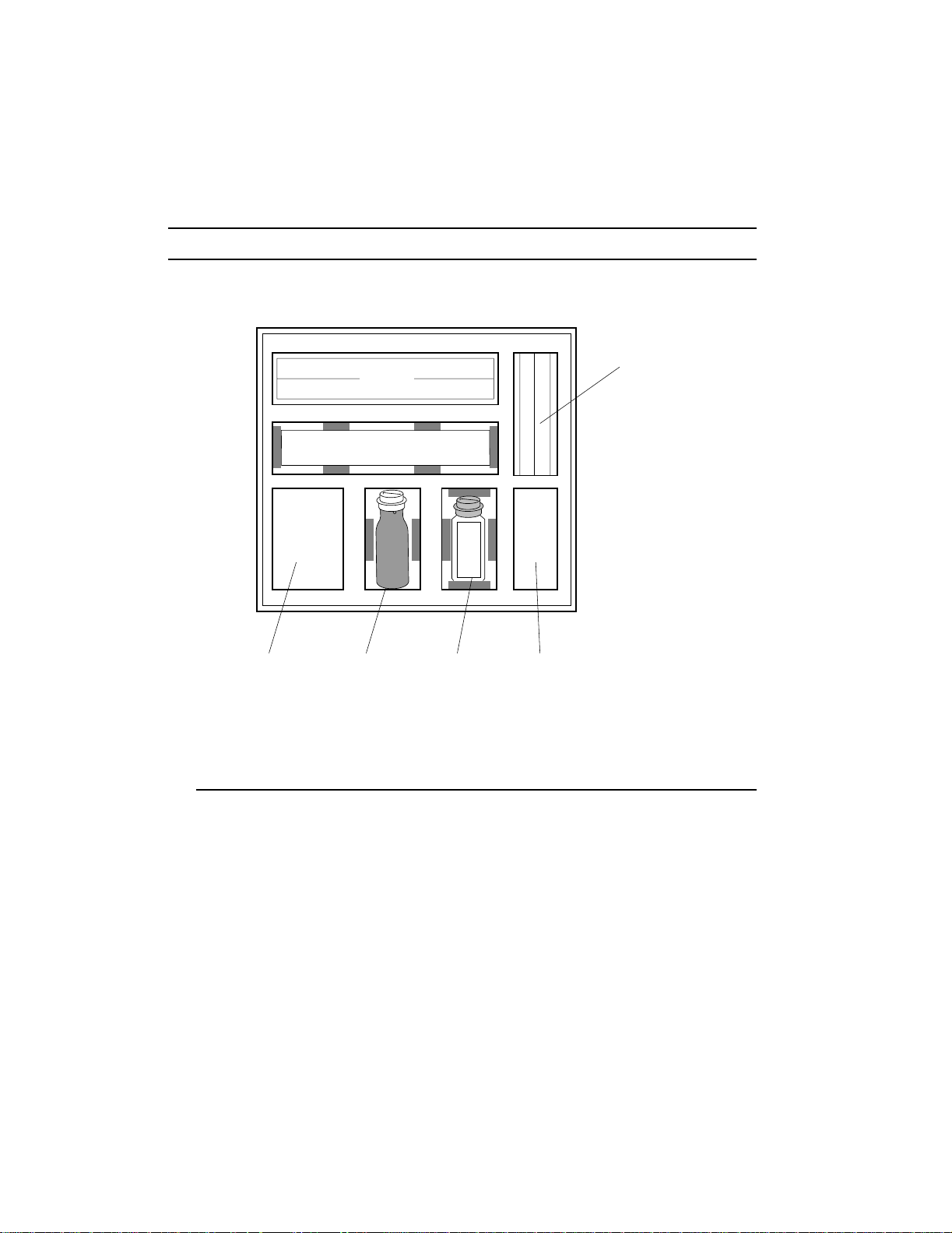
Procedure 2: Opening the Starter Kit
NOTE: Do NOT open the individual component boxes or bags at this time.
Fuser
Drum
Cleaning Cloths
Manuals
Power Cord
Paper Size Labels
Function Code Floppy
Manual Pocket Holder
Toner Developer Cleaning Brush
Ozone Filter
Figure 2-8 Starter Kit Box Contents (Packed)
Transfer assembly
2-10 Installation
Page 20
Procedure 2: Opening the Starter Kit
Table 2-2 Components Checklist
Component Quantity
Fuser 1
Drum 1
Transfer assembly 1
Toner bottle 1
Developer bottle 1
Cleaning brush 1
Installation manua l 1
User manual 1
Technical Reference manual 1
Paper Specification manual 1
Paper size car ds 3 sheets
Power cord 1
Ozone filter 1
Cleaning cloths 1 pkg
Function Code floppy 1 pkg
Installation
NOTE: Check the label on the fuser box and make sure you have the correct
voltage for your installation. The fuser comes in two versions,
120-127VAC or 200-240VAC. 120 -127VAC is more commonly used in
North America; 200 -240 VAC is more commonly used in Europe.
If you received the wrong version, call your supplier for a replacement
fuser.
Go to Procedure 3: Unpacking the Printer.
Installation 2-11
Page 21
Procedure 3: Unpacking the Printer
Procedure 3: Unpacking the Printer
NOTE: Save the printer shipping materials in case they are needed to transport
the printer to a new location. Instructions for packing your printer for
shipment are included in Packing and Shipping.
WARNING:The printer weighs 298 pounds (135 kg). Moving the printer requires
two people.
1. Use fingers or pliers to turn the plastic lock inserts counterclockwise and pull out, as
shown in Figure 2-9, Removing Plastic Lock Inserts.
2. Remove all 16 plastic lock inserts.
Figure 2-9 Removing Plastic Lock Inserts
2-12 Installation
Page 22
Procedure 3: Unpacking the Printer
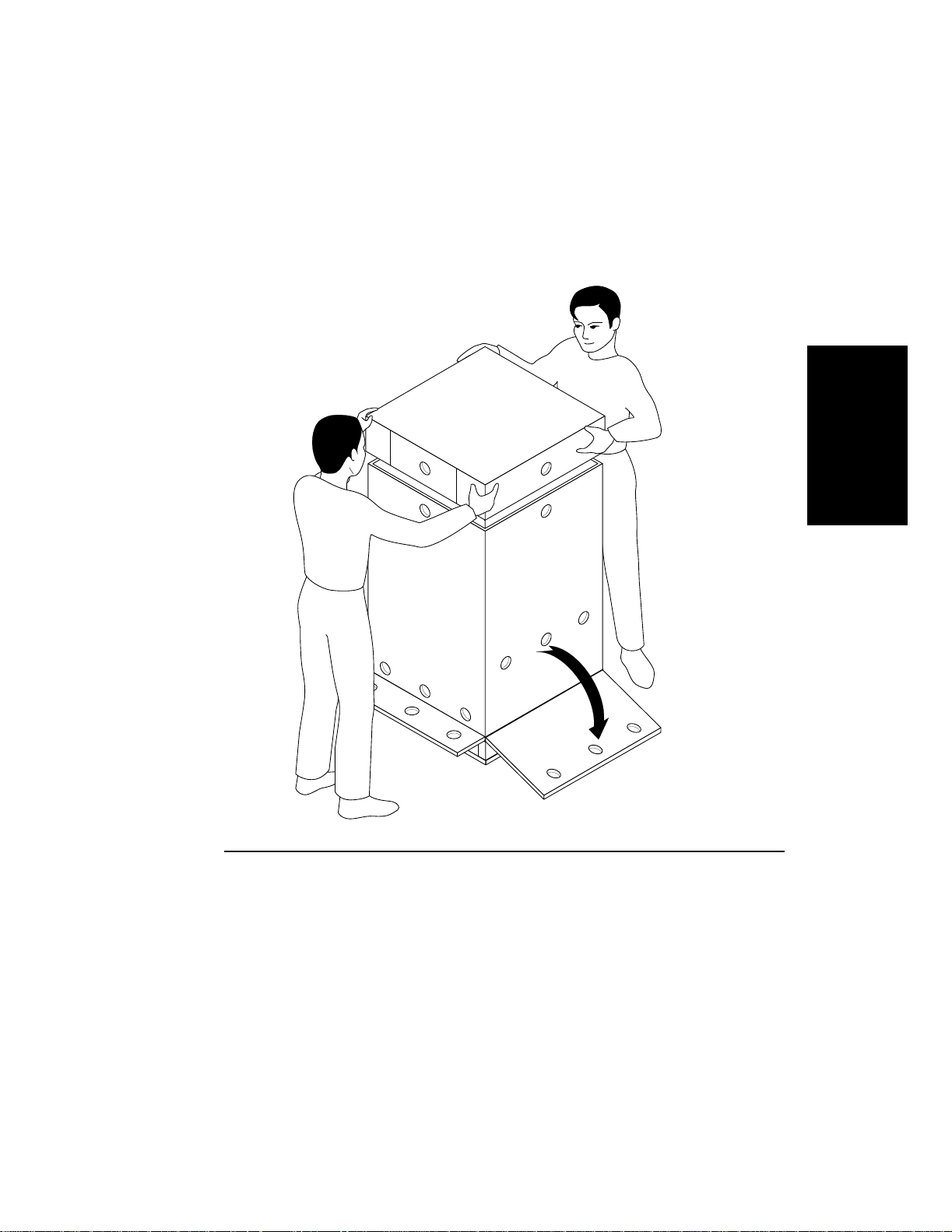
3. Lower the ramp and then remove the lid as shown in Figure 2-10.
Installation
Figure 2-10 Removi ng Lid
Installation 2-13
Page 23
Procedure 3: Unpacking the Printer
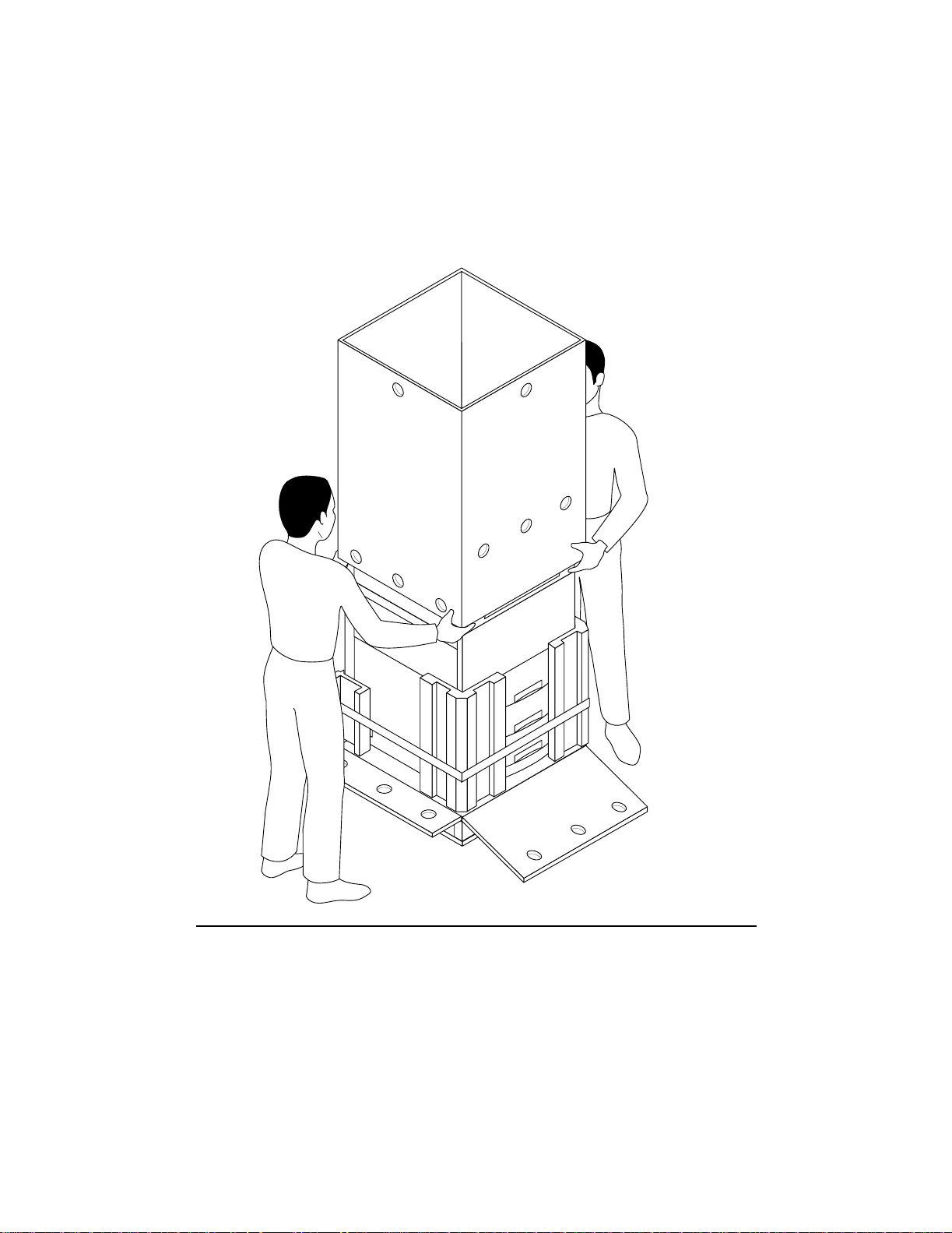
4. Remove the cardboard sleeve as shown in Figure 2-11.
Figure 2-11 Removing Sleeve
2-14 Installation
Page 24
Procedure 3: Unpacking the Printer
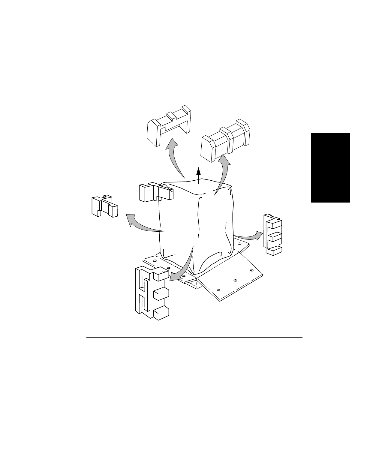
5. Cut the tape holding the lower shipping retainers and remove them as shown in
Figure 2-12.
Installation
Figure 2-12 Removing the Shipping Retainers
6. Remove the nylon cover.
Installation 2-15
Page 25
Procedure 3: Unpacking the Printer
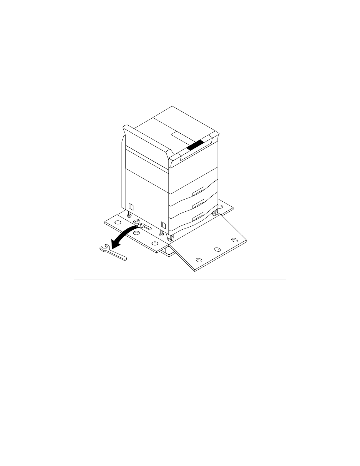
7. Remove the wrench taped to the pallet, as shown in Figure 2-13.
Figure 2-13 Removi ng the Wrench
2-16 Installation
Page 26
Procedure 3: Unpacking the Printer
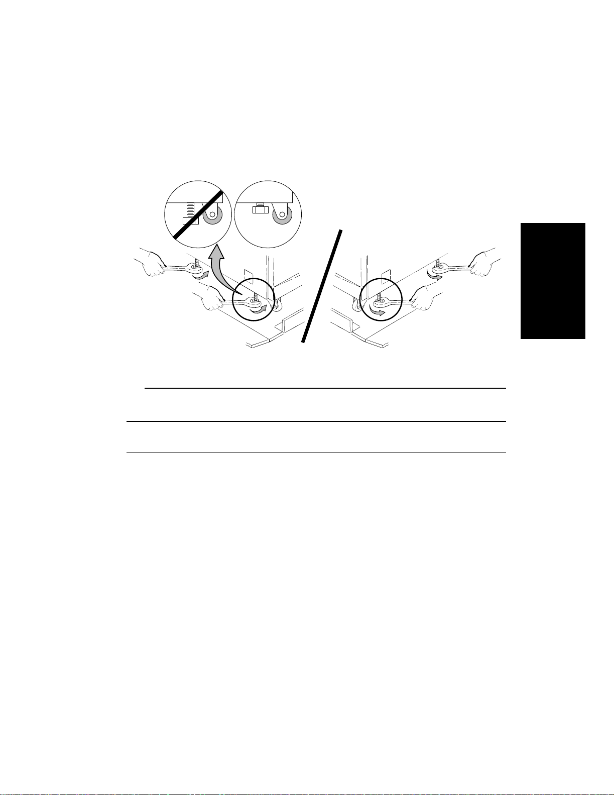
8. Use the wrench to raise all four leveling bolts by turning the leveling bolts counter-
clockwise as far as they will go. See Figure 2-14.
Figure 2-14 Raising the Leveling Bolts
Installation
CAUTION: Make sure all four leveli ng bolts are fully raised before moving the
printer or damage may occur.
Installation 2-17
Page 27
Procedure 3: Unpacking the Printer
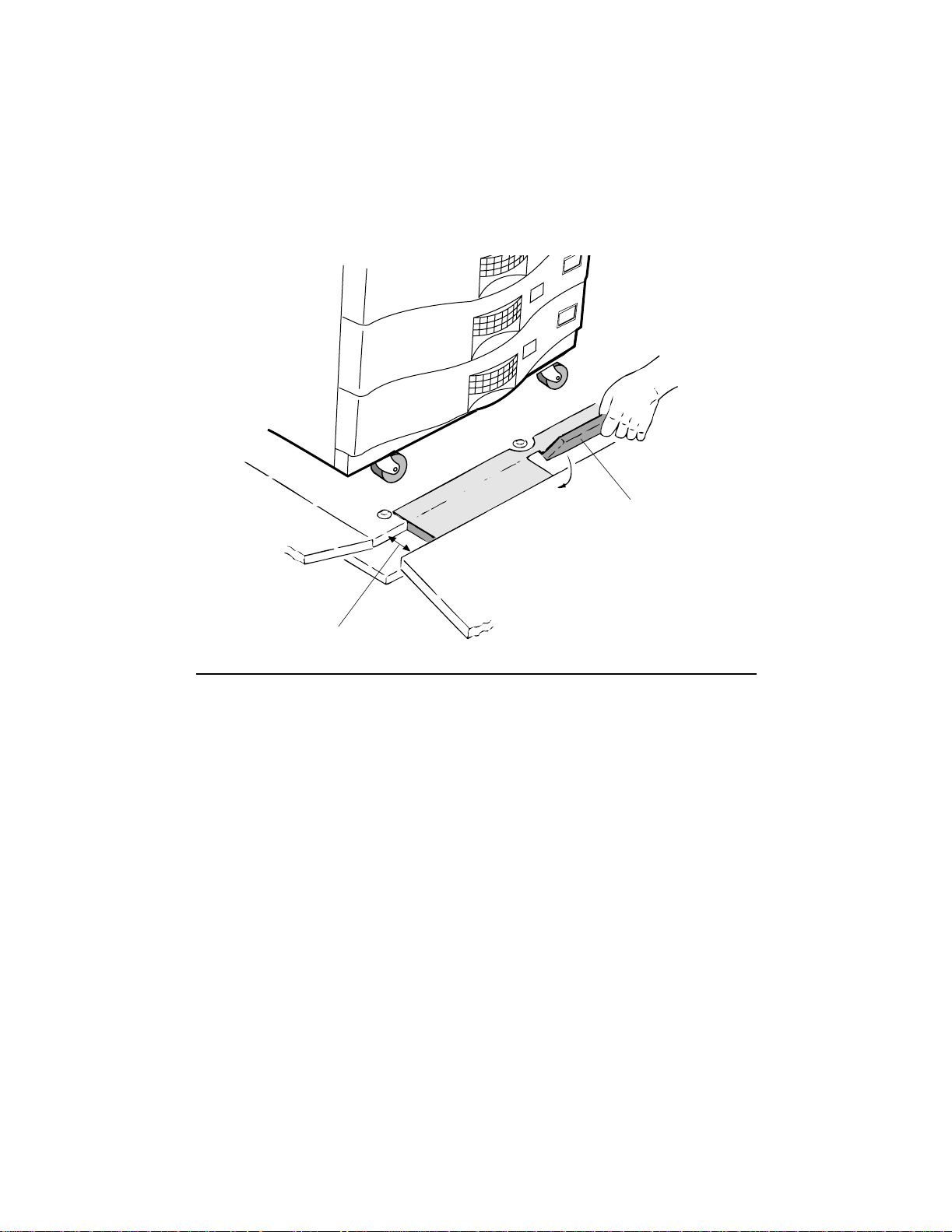
9. Flip the two small wood spacers into the groove on the slope edge of pallet ramp, as
shown in Figure 2-15.
Wooden spacer
Groove on slope edge
Figure 2-15 Securing Wood Spacers
2-18 Installation
Page 28
Procedure 3: Unpacking the Printer
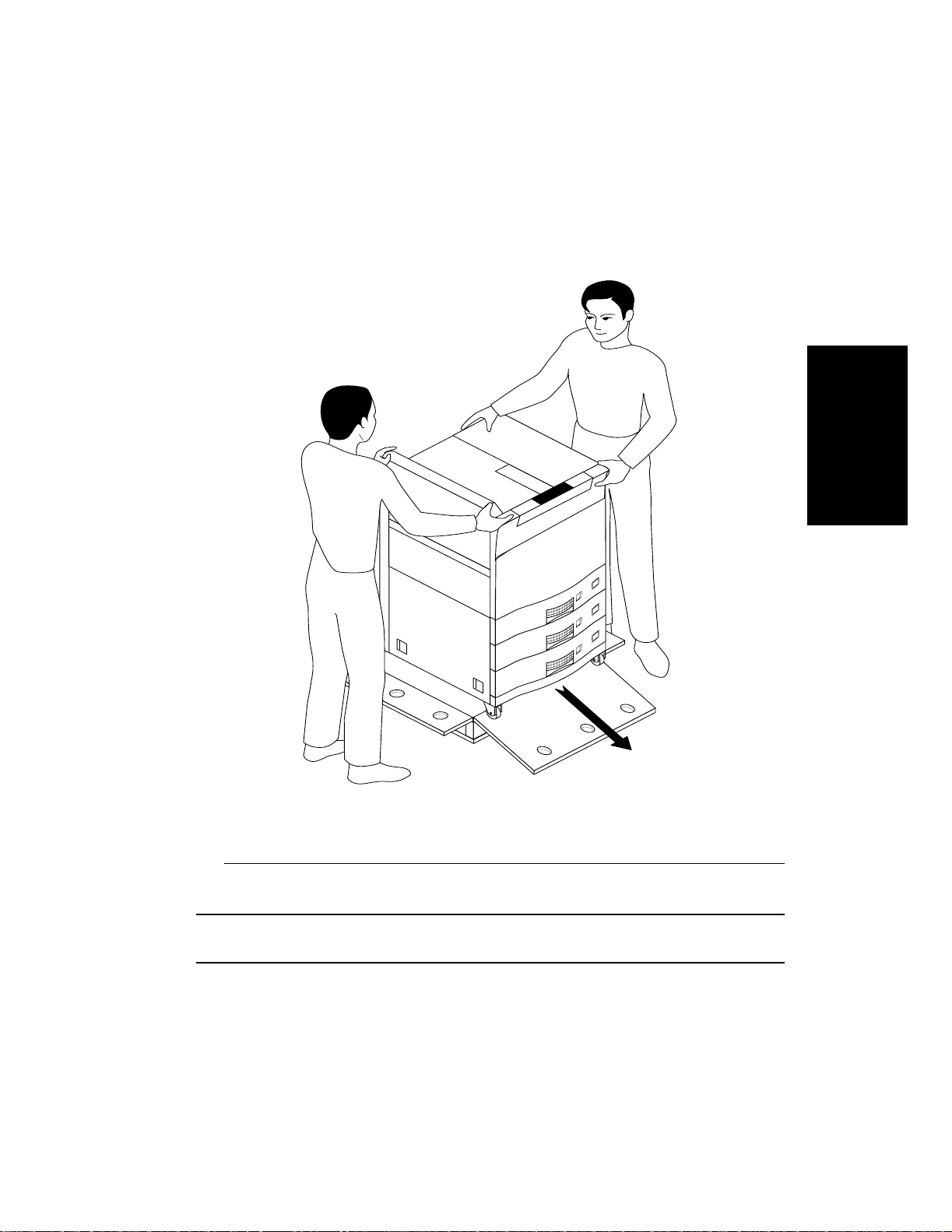
10. Move the printer off the pallet by carefully sliding it down the slope edge of the pallet
ramp, as shown in Figure 2-16. Then move the printer to the installation location.
Installation
Figure 2-16 Unloading the Printer from the Pallet
CAUTION: While moving the printer, use two people. Be careful not to subject it
to strong vibration.
Installation 2-19
Page 29
Procedure 3: Unpacking the Printer
NOTE: If the printer is not close to its final location, please move the printer to
its final location before proceeding.
11. Remove all shipping tape attached to the exterior of the printer, as shown in
Figure 2-17.
Shipping tape
....
.
.
.
.
.
.
.
.
.
.
.
.
.
.
Figure 2-17 Exterior Shipping Tape
12. Proceed to Procedure 4: Getting To Know Your Printer.
2-20 Installation
Page 30
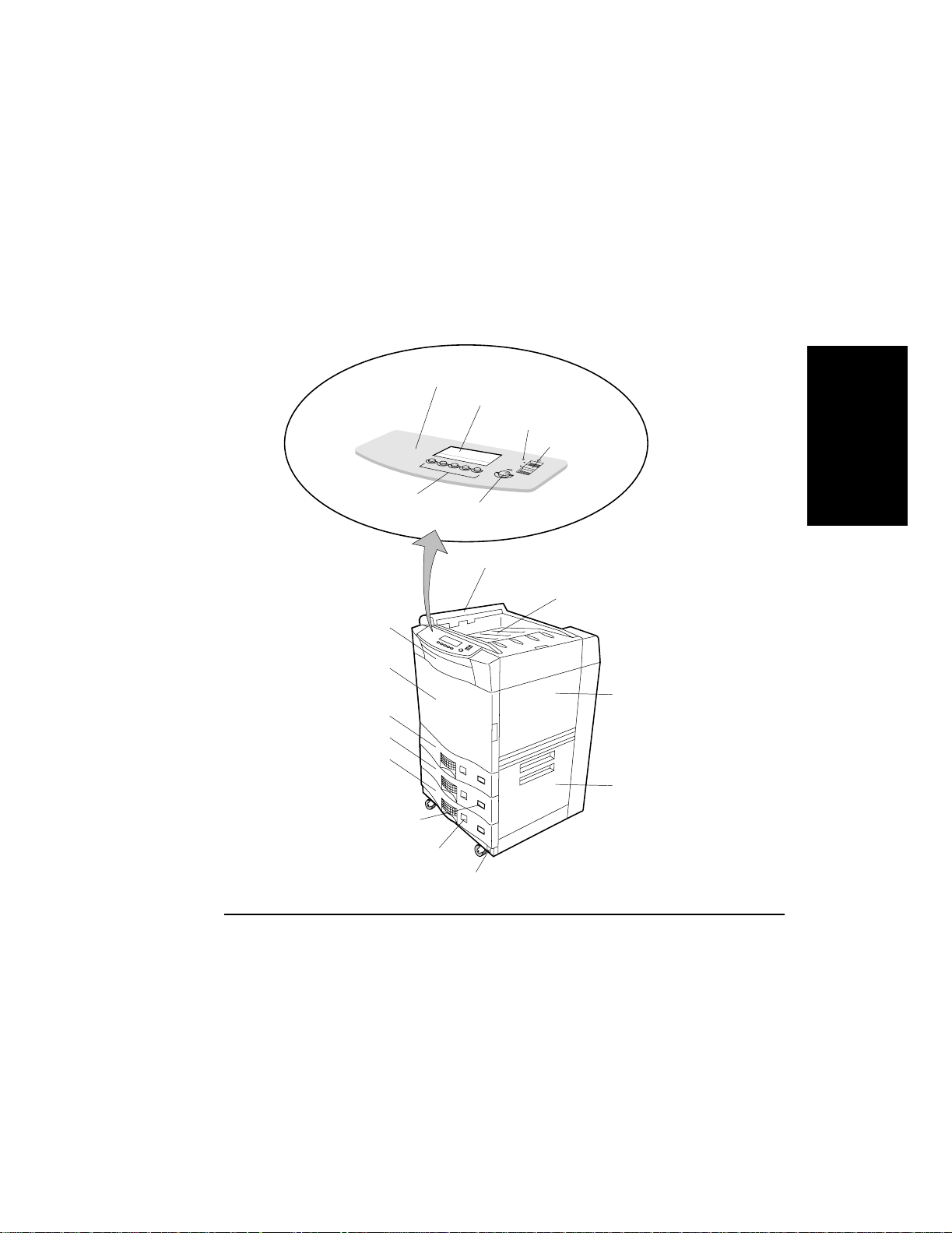
Procedure 4: Getting To Know Your Printer
Procedure 4: Getting To Know Your Printer
Now that your printer is unpacked, familiarize yourself with the printer features and components. Figure 2-18, identifies the front and side view features of the printer.
Control panel
LCD Panel (64 x 240 dots)
Power save indicator
.
.
.
.
.
.
.
.
.
.
.
.
.
.
.
.
.
.
Standby switch
ON
Function
buttons
Display
Contrast control
Ejection unit
Paper output tray
Front cover
....
.
.
.
.
.
.
.
.
.
.
.
.
.
.
Front door
Tray1
Tray2
Tray3
Paper size indicators
Paper level indicators
Main power switch
Figure 2-18 Printer Features, Front and Side View
Installation
Upper right cover
Lower right cover
Installation 2-21
Page 31

Procedure 4: Getting To Know Your Printer
Figure 2-19, identifies the rear view features of the printer.
Mounting holes
for manual pocket
Parallel
interface
connector
RS 232C/422A
interface connector
Ozone filter holder
HCO connector
HCI connector AC inlet
Figure 2-19 Printer Features, Rear View
2-22 Installation
Lower connector not used
( for future functionality)
Page 32

Procedure 4: Getting To Know Your Printer
Figure 2-20, identifies features inside the front door.
Brush holder
Location for fuser
Location for Drum
(Foam Shipping Retainer)
Transfer assembly guide
Sponge Shipping Retainer
....
.
.
.
.
.
.
.
.
.
.
.
.
.
.
PULL OUT
Installation
Figure 2-20 Printer With Front Door Open
Installation 2-23
Page 33

Procedure 4: Getting To Know Your Printer
Figure 2-21, identifies features inside the upper right cover.
Toner filler flap
Developer filler flap
....
.
.
.
.
.
.
.
.
.
.
.
.
.
.
Toner collector bottle
Space for
developer purge bottle
Figure 2-21 Printer With Upper Right Cover Open
Proceed to Procedure 5: Inside the Front Door.
2-24 Installation
Page 34

Procedure 5: Inside the Front Door
Procedure 5: Inside the Front Door
This procedure describes how to install and prepare the components within the printer’s
front door. In this procedure you will:
• Remove packing material from inside front door
• Identify Starter Kit contents
• Install the Fuser
• Install the Drum
• Install the Transfer Assembly
• Install Cleaning Brush
Removing Packing Material From Inside the Front Door
1. Open the front door.
2. While holding the transfer assembly guide, remove sponge retainer, then lower the
guide. See Figure 2-22.
Transfer assembly guide
Sponge retainer
PULL OUT
Installation
Figure 2-22 Removing Sponge Retainer
Installation 2-25
Page 35

Procedure 5: Inside the Front Door
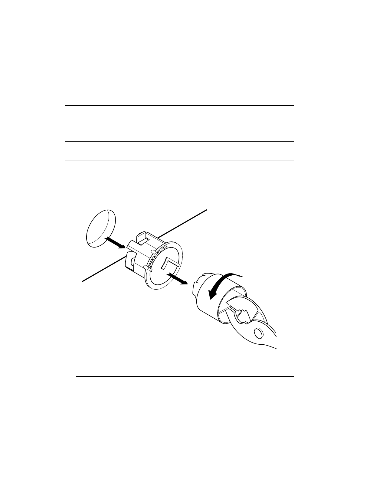
3. Turn Lever b1 to the right to the OPEN position. See Figure 2-23.
4. Pull out foam retainer.
Foam retainer
PULL OUT
Lever b1
Figure 2-23 Removing Foam Retainer
2-26 Installation
Page 36

Procedure 5: Inside the Front Door
5. Remove magnetic roller protector, as shown in Figure 2-24.
Magnetic roller
protector
Installation
Figure 2-24 Removing Magnetic Roller Protector
Installation 2-27
Page 37

Procedure 5: Inside the Front Door
6. Figure 2-25, shows where the components are installed in this procedure.
Space for drum
Space for fuser
Space for transfer assembly
Figure 2-25 Inside the Front Door
2-28 Installation
Page 38

Procedure 5: Inside the Front Door
Starter Kit Contents (Unpacked)
Now that you are ready to install the components, familiarize yourself with the printer
components you will be using. Figure 2-26, shows the components shipped in the Starter
Kit box after they have been unpacked.
LGR LTR LGL
A3 A4 A5
EXEC B4 B5
Toner
Cleaning cloths
Developer
Transfer assembly
Drum
Manual pocket
Power Cord
Cleaning brush
Parallel cable
Paper size cards
Fuser
Ozone Filter
Manuals
Installation
Function Code
Floppy
Figure 2-26 Starter Kit Box Contents (Unpacked)
Installing the Fuser
1. Locate the fuser in the Starter Kit. See Figure 2-8.
2. Remove the fuser from its packaging.
Installation 2-29
Page 39

Procedure 5: Inside the Front Door
NOTE: Check the voltage indication on the fuser. It is marked 120V-127V or
200V-240V. If you did not receive the correct f user for your installation,
contact your supplier for a replacement.
3. Push the fuser all the way into the printer until it stops. See Figure 2-27, below. Make
sure the fuser is properly seated.
Fuser
Figure 2-27 Installing the Fuser
2-30 Installation
Page 40

Procedure 5: Inside the Front Door
4. Maintain pressure on the fuser and finger-tighten the Fuser Locking Knob clockwise
to engage the frame and secure the fuser in position. See Figure 2-28.
NOTE: If the fuser does not seat properly, do not force it. Instead, refer to Figure
2-29, on page 2-32, while following the next two steps.
Fuser locking knob
Decurler roller knob
Installation
Figure 2-28 Tighten Fuser Locking Knob
1. Hold the fuser up against the printer using light pressure.
2. Carefully rotate the Decurler Roller Kno b clockwise until the fuser seats flush against
the printer.
Installation 2-31
Page 41

Procedure 5: Inside the Front Door
Decurler roller knob
Fuser locking knob
Figure 2-29 Securing the Fuser
2-32 Installation
Page 42

Procedure 5: Inside the Front Door
Unpacking the Drum
1. Locate the drum packaged in the Starter Kit. See Table 2-8, “Starter Kit Box Contents
(Packed),” on page 2-10.
2. Open the vacuum sealed bag containing the drum and remove the contents, as shown
in Figure 2-30.
3. Hold the drum by the handle o n top, set it on a solid surf ace, and caref ully remov e the
protective cover from the drum.
NOTE: Do not touch the surface of the drum. Finger prints and scratches on the
surface of the drum may adversely affect print quality.
Drum
Installation
Figure 2-30 Unpacking the Drum and Removing the Protective Cover
Installation 2-33
Page 43

Procedure 5: Inside the Front Door
Installing the Drum
1. Make sure Lever b1 is in the OPEN position.
2. Use the drum handles on the top and front to insert the drum along the guide rails until
it stops, as shown in Figure 2-31. Push the drum in as far as the it will go to ensure
correct positioning.
NOTE: Make sure the alignment pins on the printer line up with the alignment-
pin holes on the drum.
Alignment
pin holes
Top handle
Guide rails
Drum alignment
pins
Lever b1
Front handle
Figure 2-31 Inserting the Drum
2-34 Installation
Page 44

Procedure 5: Inside the Front Door
3. Gently push the drum unit onto the positioning pins, maintain pressure on the drum,
and finger-tighten the Drum Locking Knob clockwise to engage the frame and secure
the drum, as shown in Figure 2-32.
Drum locking knob
Drum locking pins
Installation
Figure 2-32 Securing the Drum
LTR
Installation 2-35
Page 45

Procedure 5: Inside the Front Door
Installing the Transfer Assembly
1. Open the box in the Starter Kit that contains the transfer assembly. See Figure 2-8, on
page 2-10.
2. Remove the transfer assembly from its packaging.
3. Using the alignment pin located on the end of the transfer assembly, insert the alignment pin of the transfer assembly into the left rail of the transfer assembly guid e at a
slight angle and push in until it clicks into place. See Figure 2-33.
CAUTION: As you handle the transfer assembly, avoid contact or damage to the
transfer wire contained in the assembly.
Transfer assembly guide
Transfer assembly
Transfer assembly guide
Pin
Transfer assembly
Wire
Figure 2-33 Inserting the Transfer Assembly
2-36 Installation
LTR
Page 46

Procedure 5: Inside the Front Door
4. Lift the transfer assembly guide until it locks in place, as shown in Figure 2-34.
5. Turn Lever b1 counterclockwise to the SET position.
NOTE: The front door will not close unless Lever b1 is in the SET position.
Transfer assembly
guide
Figure 2-34 Securing Transfer Assembly
Lever b1
Installation
Installation 2-37
Page 47

Procedure 5: Inside the Front Door
Installing the Cleaning Brush
1. Locate the cleaning brush (packed in Starter Kit). See Figure 2-8, on page 2-10.
2. Remove from plastic bag and place the cleaning brush in the front door, as shown in
Figure 2-35.
Front door
....
.
.
.
.
.
.
.
.
.
.
.
.
.
.
Cleaning brush holder
Figure 2-35 Clea ning Brush Holder
3. Close the printer’s front door.
4. Proceed to Procedure 6: Installing Ozone Filter and Manual Pocket.
2-38 Installation
Page 48

Procedure 6: Installing Ozone Filter and Manual Pocket
Procedure 6: Installing Ozone Filter and Manual Pocket
In this procedure you will:
• Install the ozone filter
• Install manual pocket
Installing the Ozone Filter
1. Locate the ozone filter packaged in the Starter Kit. See Figure 2-8, on page 2-10.
2. Remove and insert the new ozone filter in its holder located on the rear cover.
See Figure 2-36.
Installation
Handle
Figure 2-36 Inserting the Ozone Filter
Ozone filter holder
Installation 2-39
Page 49

Procedure 6: Installing Ozone Filter and Manual Pocket
Installing the Manual Pocket
1. Locate the manual pocket packaged in the Starter Kit. See Figure 2-8, on page 2-10.
2. Remove from box and mount the manual pocket on the rear of the printer. See
Figure 2-37.
Manual pocket
Mounting holes
Figure 2-37 Installing the Manual Pocket
3. Proceed to Procedure 7: Removing Paper Tray Packing Material.
2-40 Installation
Page 50

Procedure 7: Removing Paper Tray Packing Material
Procedure 7: Removing Paper Tray Packing Material
NOTE: Paper will be added in a later procedure.
In this procedure you will:
• Remove packing material from paper trays
Removing Packing Material From Paper Trays
1. Pull out the paper trays one at a time. See Figure 2-38.
....
.
.
.
.
.
.
.
.
.
.
.
.
.
.
Installation
Figure 2-38 Pulling out Paper Tray
Installation 2-41
Page 51

Procedure 7: Removing Paper Tray Packing Material
2. Remove the foam packing material from each tray. See Figure 2-39.
Packing
material
Figure 2-39 Removing Foam Packing Material
3. Close each tray.
4. Proceed to Procedure 8: Powering On the Printer.
2-42 Installation
Page 52

Procedure 8: Powering On the Printer
Procedure 8: Powering On the Printer
In this procedure you will:
• Connect the power cord
• Power on the printer
Connecting Power Cord
Connect the power cord as follows:
1. Locate the power cord included in the Starter Kit. See Figure 2-8, on page 2-10.
NOTE: Use only the power cord supplied with the printer. This power cord is
keyed for your printer and should be used with the printer at all times.
WARNING: The printer relies upon grounding for protection against electric
shock and to assure compliance with Electromagnetic Compatibility
Regulations. Always connect printer to a proper grounded outlet.
Installation
Installation 2-43
Page 53

Procedure 8: Powering On the Printer
2. Insert the power cord plug, female side in the printer and male side in the AC power
(grounded) outlet, as shown in Figure 2-40.
Grounded outlet
Figure 2-40 Connecting the Power Cord
Power On the Printer
3. Locate the main power switch and standby switch as shown in Figure 2-41.
2-44 Installation
Page 54

Procedure 8: Powering On the Printer
ON
....
.
.
.
.
.
.
.
.
.
.
.
.
.
.
Standby switch
ON
Installation
OFF
Main power switch
Figure 2-41 Standby Switch and Main Power Switch
4. Turn on the main power switch.
5. Turn on the standby switch, as shown in Figure 2-42, by holding the switch in the up
position momentarily.
Standby switch
.
.
.
.
.
.
.
.
.
.
.
.
.
.
.
.
.
.
MODEL D640
5000
ON
Figure 2-42 Turning On the Standby Switch
Installation 2-45
Page 55

Procedure 8: Powering On the Printer
6. If you do not see anything on the display, turn the contrast control knob to the
2:00 o’clock (1400) position, as shown in Figure 2-43.
MODEL D640
5000
.
.
.
.
.
.
.
.
.
.
.
.
.
.
.
.
.
.
Contrast control
ON
Figure 2-43 Contrast Control Knob
Control Panel Display at Power On
Figure 2-44, shows the control panel display screen at power on for initial installation.
Developer Injection
Open right door and rear flap
then Fill new developer
then Press Done
LTR
LTR
LTR
Done Exit
Figure 2-44 Control Panel Screen at Installation Power-On
You are now ready to load the toner and developer. The next procedure, Procedure 9:
Adding New Supplies, describes these steps.
2-46 Installation
Page 56

Procedure 9: Adding New Supplies
Procedure 9: Adding New Supplies
Before addi ng the developer as described in Figure 2-4 4, you need to remove a shipping
protector and add toner.
In this procedure you will:
• Remove plastic shipping protector
• Install Toner
• Install Developer
• Install Developer Purge bottle
Removing Plastic Shipping Protector
1. Open front door.
2. Turn Lever b1 to the right to the OPEN position (see Figure 2-45).
NOTE: Lever b1 should be in the OPEN position when removing the shipping
protector.
Lever b1
Installation
Front door
Figure 2-45 Lever b1
....
.
.
.
.
.
.
.
.
.
.
.
.
.
.
Installation 2-47
Page 57

Procedure 9: Adding New Supplies
3. Open upper right cover.
4. Slowly and firmly lift up then pull down and out at an angle to remove plastic protective cover. See Figure 2-46.
NOTE: A small amount of toner may spill when this protector is removed.
Remove slowly to avoid any spillage. If toner does spill, use the supplied
cleaning cloths to clean it up.
....
.
.
.
.
.
.
.
.
.
.
.
.
.
.
Clear plastic protector
Figure 2-46 Removing Plastic Protective Cover
5. Turn Lever b1 counterclockwise to the SET position.
6. Close the front door.
You are now ready to add the toner.
2-48 Installation
Upper right cover
Page 58

Procedure 9: Adding New Supplies
Adding Toner
1. Locate and remove the toner bottle from the Starter Kit. See Figure 2-8, on page 2-10.
2. Remove the toner bottle from its packaging.
3. Open the toner fill flap (front flap), as shown in Figure 2-47.
Toner fill flap
Installation
Figure 2-47 Opening the Toner Fill Flap
CAUTION: Check the toner bottle cap and make sure it is closed before shaking
the bottle.
4. Shake the contents of the toner bottle to loosen any toner that has settled and packed
during shipment. See Figure 2-48 .
Figure 2-48 Shake Toner Bottle
Installation 2-49
Page 59

Procedure 9: Adding New Supplies
5. Line up the guide pins on the bottle with the guide pin openings on the toner fill.
Insert and turn the toner bottle clockwise 180° to start filling. See Figure 2-49.
Toner bottle
Guide pin
Figure 2-49 Filling the Toner
NOTE: It takes about 30 seconds for the bottle to empty into the toner hopper.
2-50 Installation
Page 60

Procedure 9: Adding New Supplies
6. When empty, turn the toner bottle counterclockwise 180° and remove, as shown in
Figure 2-50.
Empty toner bottle
Installation
Figure 2-50 Removi ng the Toner Bottle
Installation 2-51
Page 61

Procedure 9: Adding New Supplies
7. Close the toner fill flap, as shown in Figure 2-51.
Toner fill flap
Figure 2-51 Closing the Toner Fill Flap
8. Discard the toner bottle.
NOTE: The toner bottle is made of recyclable materials. Dispose of in
accordance with local regulations.
2-52 Installation
Page 62

Procedure 9: Adding New Supplies
Installing the Developer
1. Locate and remove the Developer from the Starter Kit.
2. Remove the developer bottle from its packaging.
3. Open the developer fill flap, as shown in Figure 2-52.
Developer fill flap
Installation
Figure 2-52 Opening the Developer Fill Flap
Installation 2-53
Page 63

Procedure 9: Adding New Supplies
4. Line up the guide pins on the bottle with the guide pin openings on the developer fill.
Insert and turn the developer bottle clockwise 180° to start filling, as shown in
Figure 2-53.
Developer bottle
Figure 2-53 Filling the Developer
2-54 Installation
Guide pin
Page 64

Procedure 9: Adding New Supplies
5. When almost empty, gently tap the developer bottle to dislodge any remaining devel-
oper as shown in Figure 2-54.
Developer bottle
Installation
Figure 2-54 Tapping the Developer Bottle
Installation 2-55
Page 65

Procedure 9: Adding New Supplies
6. Turn the developer bottle counterclockwise 180° and remove, as shown in
Figure 2-55.
Empty developer bottle
Figure 2-55 Removing the Developer Bottle
NOTE: Do not discard the empty bottle, it is used in a later step.
2-56 Installation
Page 66

Procedure 9: Adding New Supplies
7. Close the developer fill flap, as shown in Figure 2-56.
Figure 2-56 Closing the Developer Fill Flap
Installation
8. Press the
Figure 2-57, since you are installing the developer for the first time, you do not have
to worry about the old bottle.
Developer Injection Complete
Remove and Cap Old Bottle
Install Empty New Bottle
Close Cover and Press Done
Figure 2-57 Developer Complete
9. Before you close the cover, proceed to the next section “Installing Developer Purge
Bottle.”
Done button on the Control Panel. You will see the screen sh own in
Done
Installation 2-57
Page 67

Procedure 9: Adding New Supplies
o
Installing Developer Purge Bottle
1. Remove small cap on the side of the developer bottle.
2. Turn cap around and place in the storage location, as shown in Figure 2-58.
Empty bottle
Cap in storage locati
Figure 2-58 Installing Developer Purge Bottle
3. Insert developer purge bottle into storage position.
NOTE: The bottle will not fit into the storage position if the cap is not moved.
2-58 Installation
Page 68

Procedure 9: Adding New Supplies
4. Close the upper right cover and press Done on the Control Panel. You will see the
screen shown in Figure 2-59.
TRAY1 out of paper
Load paper
PCL 12.145
Offline
Online
Offline Custom
Figure 2-59 Tray 1 Not Ready
You are now ready to set the trays, and load the paper. The next procedure,
Procedure 10: Setting the Paper Trays, describes these steps.
Menu Test PapSize
600dpi
LTR
LTR
LTR
Installation
Installation 2-59
Page 69

Procedure 10: Setting the Paper Trays
Procedure 10: Setting the Paper Trays
Before you can print you must first set the paper trays.
In this procedure, you will:
• Set the paper tray size
• Load paper
• Configure the printer
Setting the Paper Trays
1. Pull the upper paper tray out until it stops. See Figure 2-60.
Tray
Figure 2-60 Pulling out the Tray
To change the tray paper size, perform the following steps, otherwise proceed to the next
section “Loading Paper”.
NOTE: The printer is preset for letter (LTR) size paper.
2-60 Installation
Page 70

Procedure 10: Setting the Paper Trays
1. Each paper guide has a blue locking device, as shown in Figure 2-61.
Guides
(3) Locking devices
Figure 2-61 Paper Guides
2. Turn the blue locking device, for each paper guide, counterclockwise to the OPEN
position. See Figure 2-62.
Installation
S
E
O
L
O
C
LTR
LGR
P
E
N
Paper size
Figure 2-62 Locking Device
3. Lift paper guides and place in new paper size location. The paper size can be seen in
the round circle on the paper guide. See Figure 2-62.
Installation 2-61
Page 71

Procedure 10: Setting the Paper Trays
4. Adjust each paper guide for the same paper size. See Figure 2-63.
LTR
LTR
Figure 2-63 Paper Size Locations
LGR
B4
LGL
S
E
O
L
O
C
P
E
N
B5
A5
5. Turn the blue locking device, for the paper guide, clock wise to the CLOSE position to
secure. See Figure 2-64.
C
L
O
LTR
LTR
LGR
S
E
O
P
E
N
Figure 2-64 Securing the Paper Guide
6. Close the paper tray.
To change the paper size for tray2 and tray3, perform steps 1 through 6 for each tray.
2-62 Installation
Page 72

Procedure 10: Setting the Paper Trays
Paper-Size Indicator
Perform the following steps to indicate paper sizes.
1. Open the plastic bag in the Starter Kit containing the paper-size cards.
2. Break off the label that indicates the correct paper size for each tray. See Figure 2-65.
LGR LTR LGL
A3 A4 A5
EXEC B4 B5
LGR
LTR
A3
EXEC
A4
B4
L
G
L
A5
B5
Installation
Figure 2-65 Paper-Size Labels
Installation 2-63
Page 73

Procedure 10: Setting the Paper Trays
3. Pull out each tray and push out the paper-size holder, as shown in Figure 2-66.
Paper-size holder
L
G
L
LGL
Figure 2-66 Paper-Size Holder
4. Place the paper-size label in the paper-size holder of each tray.
NOTE: You can store the remaining paper-size labels in each paper-size holder.
5. Replace the paper-size holders.
6. Close trays.
You are now ready to load the paper as described in the next section, “Loading Paper”.
2-64 Installation
Page 74

Procedure 10: Setting the Paper Trays
Loading Paper
To load the paper in the paper trays do the following:
1. Remove the paper from the package with the seam side up as shown in Figure 2-67.
Read the manufacturer’s label and note which side of the paper should be printed
first. Most manufacturers note this with a “Print This Side First” arrow.
PRINT THIS SIDE FIRST
Installation
Figure 2-67 Removing the Paper From the Package
2. Inspect the paper for inden ted or interlocked edg es, bent corners, wrinkled sheets, and
excess glue from the wrapper. Discard any damaged sheets.
3. Open tray1.
Installation 2-65
Page 75

Procedure 10: Setting the Paper Trays
4. Load the paper in the tray print side down. Do not stack the paper above the paper-full
mark. See to Figure 2-68).
Paper
LTR
Paper-full mark
Figure 2-68 Loading the Paper in the Tray
• If the paper is not placed with the correct side down, the paper may jam or have
excessive curl.
• Never mix the types of paper loaded in a tray. Mixing paper can result in multiple
sheet feeds and other paper handling problems.
5. Close the tray.
6. Repeat the above steps (1 through 5) when loading paper in the two remainin g trays.
NOTE: Never load paper above the full mark or you may get paper jams and
skewed print.
2-66 Installation
Page 76

Procedure 10: Setting the Paper Trays
Paper Level Indicator
The blue paper level indicator shows t he appr oximat e l evel of the p aper i n the tray. When
the indicator is in the upper position, the paper tray is full. As th e paper level lowers, so
does the indicator. See Figure 2-69, Paper Level Indicator.
Installation
Figure 2-69 Paper Level Indicator
Installation 2-67
Page 77

Procedure 10: Setting the Paper Trays
Control Panel Display
The right hand side of the Control Panel display shows a diagram of the printer. The display includes installed paper trays and associated paper sizes as shown in Figure 2-70.
Printer diagram
Ready - - free
JUN 18 05:32.23
PCL
Offline
Online
Offline
Figure 2-70 Control Panel Display, Main Screen
Custom Menu Test PapSize
600dpi
LTR
LTR
LTR
• LTR indicates letter size paper and that the paper tray has paper.
• LTR indicates letter size paper and that the paper tray is empty.
The display also shows the selected paper path, from the selected tray, ou t to the selected
paper output.
Configuring the Printer
1. Press the PapSize button on the Main Screen (see Figure 2-70) to display the PapSize menu shown in Figure 2-71.
PapSize
tray1size =LETTER
tray2size =LETTER
tray3size =LETTER
Online
Online
Figure 2-71 PapSize Menu
The PapSize submenu provides access to paper size selections for each tray.
2-68 Installation
Page 78

Procedure 10: Setting the Paper Trays
Using the Menus
The function buttons shown in Figure 2-72 are used to maneuver in and make selections
within the submenus. Table 2-3 describes each submenu button.
PapSize
tray1size =LETTER
tray2size =LETTER
tray3size =LETTER
HCIsize =LETTER
Online
Online
Up Down Right Left
Figure 2-72 Submenu Buttons
Table 2-3 Submenu Buttons Description
The
up arrow button moves the selection back to the prev ious item
on the submenu list.
down arrow button moves the selection to the next item on the
The
submenu list.
right arrow button selects the next level of the subm enu struc-
The
ture.
left arrow button goes back to one submenu level above the cur-
The
rent one.
Installation
Refer to Chapter 2 in the User Manual for more detailed information.
Installation 2-69
Page 79

Procedure 10: Setting the Paper Trays
1. Press the
Ready - - free
JUN 18 05:32.23
PCL
Figure 2-73 Main Screen
2. Proceed to Procedure 11: Installing Function Code.
left arrow button to return to the Main Screen shown in Figure 2-73.
Offline
Online
Offline
Custom Menu Test PapSize
600dpi
LTR
LTR
LTR
2-70 Installation
Page 80

Procedure 11: Installing Function Code
Procedure 11: Installing Function Code
The D640 comes with its operating function code (software) and fonts preinstalled in the
printer. When the printer is shipped to you, the latest version of the code is shipped on diskette and may be more current than the version preinstalled in the printer.
Follow the steps in this procedure to install the latest version in your printer.
Follow these steps to update your printer software:
1. Open the front cover and locate the floppy drive, as shown in Figure 2-74.
Installation
Floppy disk drive
Front cover
Figure 2-74 Floppy Disk Drive
....
.
.
.
.
.
.
.
.
.
.
.
.
.
.
LTR
LTR
Installation 2-71
Page 81

Procedure 11: Installing Function Code
2. Locate the Function Code diskette(s) shipped in the Starter Kit. See Figure 2-8, on
page 2-10.
3. Insert the diskette into the drive as shown in Figure 2- 75.
Floppy disk drive
....
.
.
.
.
.
.
.
.
.
.
.
.
.
.
Figure 2-75 Installing Function Code
2-72 Installation
LTR
LTR
LTR
Page 82

Procedure 11: Installing Function Code
4. Press the Test button on the Main Screen shown in Figure 2-76.
Ready - - free
JUN 18 05:32.23
PCL
Offline
Online
Offline
Figure 2-76 Main Screen
5. Use the
Figure 2-77, and press the
down arrow button to scroll down and highlight filesA, as shown in
Custom Menu Test PapSize
Select button.
Test
filesA
filesC
Online
Online Select
600dpi
LTR
LTR
LTR
Installation
Figure 2-77 Test Submenu
NOTE: After pressing select, there will be a few seconds delay as the printer
reads the directory from the diskette.
6. From the filesA submenu, highlight the
to start the update process.
UPDATE.LAY file. Press Select and Online
Installation 2-73
Page 83

Procedure 11: Installing Function Code
7. After a few seconds, the printer displays this message:
Installing backup to hard disk
8. Then the printer displays this message:
Loading new Function Code
9. After about 45 seconds, the printer displays this message:
EW OK
10. After a few seconds the Control Panel display goes blank (the new function code is
resetting the main controller).
11. When the new function code has fini s hed res et tin g t h e con tr ol le r, you wi ll see the display shown in Figure 2-78.
Printer initializing
Please Wait
PCL
Offline
Online
Offline
Custom Menu Test PapSize
Figure 2-78 Printer Initializing
2-74 Installation
600dpi
LTR
LTR
LTR
Page 84

Procedure 11: Installing Function Code
12. When the printer has finished initializing, you will see the Ready message, as shown
in Figure 2-79
Ready - - free
JUN 18 05:32.23
PCL
Offline
Online
Offline
Figure 2-79 Ready (Main Screen)
13. Remove the Upgrade Function Code diskette and close the front cover.
NOTE: After you remove the Upgrade Function Code diskette, store it in a safe
place.
14. Proceed to Procedure 12: Setting the Date and Time.
Custom Menu Test PapSize
600dpi
LTR
LTR
LTR
Installation
Installation 2-75
Page 85

Procedure 12: Setting the Date and Time
Procedure 12: Setting the Date and Time
The D640 prints the current date and time on test patterns and reports (such as the Ripple
Test Pattern and the Maintenance Report). When you unpack the printer, the date and time
still has the factory settings. Set the date and time to the current va lues, following these
steps:
1. At the
Figure 2-80 Menu
2. Use the
Main Screen (shown in Figure 2-73), press Menu. You will see the screen in
Figure 2-80
Online
.
down arrow to highlight Maintenance, as shown in Figure 2-81.
Online
Online
Menu
Menu
Printing
Configuration
PCL
Comms
Maintenance
Printing
Configuration
PCL
Comms
Maintenance
Figure 2-81 Maintenance Selected
3. Press the
2-76 Installation
right arrow to highlight the Maintenance screen, shown in Figure 2-82.
Page 86

Procedure 12: Setting the Date and Time
Maintenance
Online
Online
Figure 2-82 Maintenance Settings
4. Press the
Figure 2-83 date-time
down arrow to highlight the date-time setting, as shown in Figure 2-83.
Maintenance
Online
replace
alignment
density = 10
testpages = 30
monitor = OFF
date-time
replace
alignment
density
monitor
testpages
date-time
Installation
5. Press the
Figure 2-84 Maintenance.date-time Settings
6. Press the
7. Press the
right arrow to highlight the date-time settings, as shown in Figure 2-84.
Maintenance.date-time
Online
up or down arrow to highlight the date-time setting to change.
right arrow to highlight that setting.
minute
hour =16
date =16
month =16
year =16
=20
Installation 2-77
Page 87

Procedure 12: Setting the Date and Time
8. Press the
2-85. In this example of the
more selections before
of
Maintenance.date-time.date
up and down arrow to change the value of the setting, as shown in Figure
date setting, the carat (^) symbols indicate that there are
18 and after 23. The equals (=) sign indicates the current value
date, which is 20.
18
19
=
20
21
22
23
Online
Select
Figure 2-85 Maintenance.date-time.date
9. When you have mov ed to the co rrect v alue, p ress
tenance.date-time
screen shown in Figure 2-84. At this poin t, you can re peat the pr o-
Select. You will return to the Main-
cedure from step 6 to change additional values, or if you are finished, press
return to th e
Main Screen and verify the correct date and time.
Date and time
Ready - - free
600dpi
JUN 18 05:32.23
PCL
LTR
LTR
Offline
Online
Offline
Custom Menu Test PapSize
LTR
Online to
Figure 2-86 Date and Time on Control Panel
Proceed to Procedure 13: Printing a Setup Report.
2-78 Installation
Page 88

Procedure 13: Printing a Setup Report
Procedure 13: Printing a Setup Report
You are now ready to print a setup report. A successful printout indicates that all printer
components are installed and are operating correctly. Keep in mind, however, that the
printer to computer connection is not yet in place.
1. Press the
Ready - - free
JUN 18 05:32.23
PCL
Figure 2-87 Main Screen
2. Select
Select button.
Test button on the Main Screen, shown below in Figure 2-87.
Offline
Online
Offline
SETUPS from the Test submenu, as shown in Figure 2-88, and press the
Custom Menu Test PapSize
Test
SETUPS
MAINT
FONTS
TABLE
TYPES
MENUS
600dpi
LTR
LTR
LTR
Installation
Online Select
Figure 2-88 Test Submenu
Figure 2-89, Sample Setup Report, Page 1, on page 2-80, shows the information reported
when you print the
3. Check the printer setup report print. It should look similar to the sample setup report
in Figure 2-89. If it does, proceed to Procedure 14: Securing the Printer.
SETUPS submenu.
Installation 2-79
Page 89

Procedure 13: Printing a Setup Report
Figure 2-89 Sample Setup Report, Page 1
If the test was unsuccessful, refer to Troubleshooting, which follows.
If the test was successful, perform installation of any accessories according to the proce-
dures in Chapter 4, Accessories. If you have no accessories to install, proceed to Procedure 14: Securing the Printer.
2-80 Installation
Page 90

Troubleshooting
Troubleshooting
In the unlikely event that the printer does not generate a printer setup report, follow these
steps:
1. If the printer does not power on (no lights or sounds), verify that it is connected to a
live power circuit, that the Main power switch is in the ON position, and the standby
switch has been moved to the ON posi tion momentarily.
2. Write down the error code if one appears on the LCD display.
3. Refer to “Printer Error Codes” in the User Manual to determine the meaning of the
error code.
4. Use the error code to check the area specified and correct the problem. In addition,
check for:
a) Styrofoam or cover did not get removed
b) Jammed paper
c) Improper installation
5. Print a test pattern, described in Procedure 13: Printing a Setup Report, on page 2-79.
6. If you are still unsuccessful, see “Where To C all For Help ” on pag e B-3. B e p repar ed
to give the service representative the error code, and any messages appearing on the
Control Panel, to assist in troubleshootin g.
Installation
Installation 2-81
Page 91

Procedure 14: Securing the Printer
Procedure 14: Securing the Printer
Place the printer on a sturdy, smooth, level surface in a well-ventilated room. Check the
printer location to make sure it meets all necessary operational requirements.
Secure the printer to the current location only if the printer is not going to be moved or you
are not installing the HCI and HCO.
1. Manually lower all four leveling bolts until they touch the floor.
2. Use the wrench to lower the leveling bolts until the wheels are just off the ground, as
shown in Figure 2-90.
LTR
LTR
LTR
(4) Leveling feet
Figure 2-90 Securing the Leveling Feet
When you have secured the printer, perform the paper tray alignment procedure in Procedure 15: Paper Path Alignment.
2-82 Installation
Page 92

Procedure 15: Paper Path Alignment
Procedure 15: Paper Path Alignment
During transportation, the paper path alignment may change slightly from the factory set
position. The following paper path alignment procedure will set the printing alignment for
each tray to ensure correct print position. This procedure looks complicated, but it is actually quite easy. After you have performed it a once or twice, it should only take a few minutes to complete.
Note: Please read through the entire procedure before performing any of
the steps.
Step 1 - Printing Alignment Sheets
When you run the alignment p rog ram from the printer’s hard drive, the printer produ ces a
set of alignment pages.
Step 2 - Measuring Alignment
By measuring the current alignment for each tray against a ref erence standard, you simply
add two numbers to determine new alignment values.
Installation
Step 3 - Setting Alignment Values
Once you have determined new values, enter them in the Control Panel and recheck the
alignment.
Installation 2-83
Page 93

Procedure 15: Paper Path Alignment
Step 1 - Printing Alignment Sheets
1. Verify that all three paper trays and the HCI (if installed) have Letter (or A4) size
paper.
2. Press the
Test button on the Main Screen, shown in Figure 2-91.
Ready - - free
JUN 18 05:32.23
PCL
Online
Offline
Offline
Figure 2-91 Main Screen
3. Use the
Figure 2-92, and press
Figure 2-92 Test Submenu
down arrow to scroll down and highlight filesC, as shown in
Online
Online Select
Custom Menu Test PapSize
Select .
Test
filesA
filesC
600dpi
LTR
LTR
LTR
LTR
2-84 Installation
Page 94

Procedure 15: Paper Path Alignment
4. From the filesC submenu shown in Figure 2-93, use the down arrow to highlight
USER_ADJ , then press Select.
C:\
Online
Online Select
Figure 2-93 FilesC Submenu
5. Use the
See Figure 2-94.
Figure 2-94 ALIGNSET.12
down arrow to highlight ALIGNSET.*
C:\USER_ADJ\
Online
Online Select
dir
USER_ADJ\
PCLS\
PS\
MAINT\
FONTS\
dir
ALIGNSET.12
1
, then press Select once.
Installation
1. The last two numbers refer to the program version number, which may be different
from the version number shown in these illustrations.
Installation 2-85
Page 95

Procedure 15: Paper Path Alignment
6. The number
Figure 2-95.
Online
Online Select
Figure 2-95 1 ALIGNSET.*
7. Press
NOTE: After pressing Online, there will be a few seconds delay as the printer
loads the program.
The printer then produces a set of alignment sheets, one from each tray (and the HCI, if it
is installed), a Simplex feed alignment ruler sheet (see Figure 2-96), which provides:
1 appears in front of the ALIGNSET.* message, as shown in
C:\USER_ADJ\
Online once.
dir
1
ALIGNSET.12
• instructions for the alignment procedure
• a reference scale to measure the alignment sheets
• a workspace to calculate alignment values and adjustments
Duplex unit alignment ruler
and a
iest alignment values (duplexv means "duplex vertical").
sheet, which measures the duplex sideways and length-
When the printer has finished printing these pages, you are ready to begin measuring the
alignment pages (Step 2).
2-86 Installation
Page 96

Procedure 15: Paper Path Alignment
Step 2 - Measuring Alignment
You will now read the adjustment values.
1. Carefully and accurately, fold the top part of the Simplex feed alignment ruler sheet,
shown below, at the Fold here line.
Adjustment scale
Simplex feed alignment ruler
Fold line
Use this ruler to align individual feeds. Do not use ruler printed on another machine to ensure main scan direction compatibility.
For each sheet from individual feeds measure the required relative adjustment and modify accordingly using the printer operator
panel.
Fold here
0+5+10
+15
+20
+25
-5
-10
-15
-20
Align with left edge of printed sheet
-25
Line on printed sheet indicates the required relative adjustment.
Direction of paper motion
Installation
Figure 2-96 Simplex Feed Alignment Ruler Sheet
Installation 2-87
Page 97

Procedure 15: Paper Path Alignment
2. On the alignment sheet for tray 1, shown in Figure 2-97, locate the Feed 1 alignment
indicator line.
3. Place the simplex feed alignment ruler sheet adjustment scale between the ends of
the arrows (at "measure between these two arrows", shown in the illustration below).
On the next page, Figure 2-98 shows how the two sheets should look when properly
positioned, with the line labeled "Align with left edge of printed sheet" positioned
against the left edge of the alignment sheet for tray 1.
Feed alignment indicator line
Feed 1: Upper tray
Direction of paper motion
Measure between these two arrows
Figure 2-97 Sample Alignment Sheet For Tray 1
2-88 Installation
Page 98

Procedure 15: Paper Path Alignment
Feed alignment indicator line
Read measurement here
Place edge here
Align with left edge of printed sheet
Measure between these two arrows
0+5+10
+15
+20
+25-5-10
-15
-20
-25
Line on printed sheet indicates the required relative adjustment.
Feed 1: Upper tray
Direction of paper motion
Direction of paper motion
Figure 2-98 Measuring Alignment With Alignment Scale
4. The arrow printed on the alignment sheet for tray 1 will intersect the simplex feed
alignment ruler sheet scale at some value, as shown in the illustration above.
Installation
Installation 2-89
Page 99

Procedure 15: Paper Path Alignment
5. Record this value in the adjustment value area for tray 1 on the simplex feed alignment ruler sheet. See Figure 2-99.
Example
Original alignment value
currently in printer
+2
Figure 2-99 Original Alignment Value and Adjustment Value
Write in adjustment
value from line
measurement
14
+2
6. Repeat steps 2 through 4 with the alignment sheets for trays 2, 3, and the HCI (if
installed).
Note: The printer still prints a sheet for the HCI even if no HCI is present.
Simply ignore this page if you don’t have an HCI connected and
paper installed in it.
7. Now read the values for duplex pages as directed in the next section.
2-90 Installation
Page 100

Procedure 15: Paper Path Alignment
Duplex (Double-Sided) Printing Alignment
Figure 2-100 illustrates the Duplex unit alignment ruler sheet, which provides a way to
measure the alignment between the printed image on the front and back sides of a doublesided page.
Installation
Figure 2-100 Duplex Unit Alignment Ruler Sheet
1. On the duplex unit alignment ruler sheet, review each side of the paper. View
through the paper. Hold the paper up to a bright light, the side with the alignment
scale towards you.
2. The sideways indicator line runs up and down the back of the page on the left. Look
for the indicator line and note where it crosses the scale on the left. Record this value
on sheet 1 at Duplex unit sideways alignment adjustment value.
3. The
lengthwise indicator line runs across the back of the page. Look for the indicator
line and note where it crosses the scale in the middle of the page. Record this value
on sheet 1 at
Duplex unit lengthwise alignment adjustment value.
Installation 2-91
 Loading...