

Page 1

D640 Cut Sheet Printer
Service Manual
Hewlett-Packard Company
C5620-90028
0699
Page 2

D640 Printer Service Manual
WARNING!
This document is intended for service-trained personnel who are aware of the hazards
involved. Procedures in this manual may expose the service person to electrical shock
hazards that could cause serious personal injury or death, and to mechanical hazards
from moving parts that may cause serious injury.
Notice
Hewlett-Packard makes no warranty of any kind with regard to this material, including,
but not limited to, the implied warranties of merchantability and fitness for a particular
purpose. Hewlett-Packard shall not be liable for errors contained herein or for incidental
or consequential damages in connection with the furnishing, performance, or use of this
material.
Hewlett-Packard assumes no responsibility for the use or reliability of its software on
equipment that is not furnished by Hewlett-Packard.
This document contains proprietary information which is protected by copyright. All
rights are reserved. No part of this document may be photocopied, reproduced, or
translated to another language without the prior written consent of Hewlett-Packard
Company. The information contained in this document is subject to change without
notice.
Printing History
The dates on the title page change only when a new edition is published.
Edition 2.0. . . . . . . . . . . . . . .February 1998
Edition 2.1. . . . . . . . . . . . . . .May 1998 (online only)
Edition 2.2. . . . . . . . . . . . . . .June 1998 (online only)
Edition 2.3. . . . . . . . . . . . . . .August 1998 (online only)
Edition 3.0. . . . . . . . . . . . . . .September 1998 (online only)
Edition 3.1. . . . . . . . . . . . . . .October 1998 (online only)
Edition 3.2. . . . . . . . . . . . . . .January 1999 (online only)
Edition 3.3. . . . . . . . . . . . . . .April 1999 (online only)
Edition 3.4. . . . . . . . . . . . . . .June 1999 (online only)
Copyright ©1999 Hewlett-Packard Company
All rights reserved.
June 1999
Please address any comments or questions to:
Publications Manager
Department LaserJet Division-Cupertino
MS 44MC
Hewlett-Packard Company
19111 Pruneridge Avenue
Cupertino, CA 95014
ii June 08, 1999
Page 3

Copyrights and Trademark Credits
D640 Printer Service Manual
Adobe™, PostScript™
Adobe Systems Incorporated which may be registered in certain jurisdictions.
Arial, Times New Roman,
Corporation.
Bi-Tronics
Helvetica
or other countries.
Macintosh
Microsoft
LAN Manager™ are trademarks of Microsoft Corporation.
Novell™ is a trademark of Novell, Incorporated.
TrueType
WordPerfect
ITC Zapf Dingbats is a U.S. registered trademark of International Typeface Corporation.
Albertus, Antique Olive, Arial, CG Omega, CG Times, Clarendon Condensed, Coronet,
Courier, Garamond, Letter Gothic, Marigold, Symbol, Times New Roman, Univers,
Univers Condensed, Wingdings are trademarks of Agfa Division of Miles Inc.
CG Times, a product of Agfa Corporation, is based on Times New Roman, a registered
trademark of Monotype Corporation PLC.
™, PCL5™, and REt™ are trademarks of Hewlett-Packard Company.
and
Univers
computer is a product of Apple Computer, Inc.
® is a U.S. registered trademark of Microsoft Corporation; Windows™ and
™ is a trademark of Apple Computer, Inc.
is a registered trademark of WordPerfect Corporation.
, PostScript II and the
and
Monotype
are trademarks of Linotype AG and/or its subsidiaries in the U.S.
PostScript Logo
are registered trademarks of the Monotype
™ are trademarks of
Centronics is a trademark of Centronics Data Computer Corp.
Intellifont is a trademark of Miles Inc.
Portions of the software in the PostScript upgrade are Copyright© 1990-1997 Pipeline
Associates, Inc. Certain portions protected by U.S. Patent No. 5,150,454.
Other product names mentioned in this manual may also be trademarks and are used
here for identification only.
June 08, 1999 iii
Page 4

D640 Printer Service Manual
Manual Conventions
Note A note denotes important information that sho uld be read.
CAUTION A CAUTION denotes a hazard. It calls attention to a procedure which, if done incorrectly or
inattentively , could damage or destroy par t or all of the product. Do no t proceed beyond a Caution
until the indicated conditions are fully understood and met.
WARNING! A WARNING! denotes a hazard. It calls attention to a procedure or practice, which, if not done
correctly or adhered to, could result in personal injury . Do not proceed beyond a WARNING! s ign
until the indicated conditions are fully understood and met.
For More Information
For a list of internal and external web sites, see 1-1.2 "Web Sites for More Information,"
on page 1-5.
iv June 08, 1999
Page 5

D640 Printer Service Manual
Contents
Chapter 1: Specifications
1-1 Introduction. . . . . . . . . . . . . . . . . . . . . . . . . . . . . . . . . . . . . . . . . . . . . . . . . . . . .1-3
1-1.1 Related Documents. . . . . . . . . . . . . . . . . . . . . . . . . . . . . . . . . . . . . . . .1-4
1-1.2 Web Sites for More Information . . . . . . . . . . . . . . . . . . . . . . . . . . . . . .1-5
1-2 Printer Specifications . . . . . . . . . . . . . . . . . . . . . . . . . . . . . . . . . . . . . . . . . . . . .1-6
1-2.1 Printer General Specifications. . . . . . . . . . . . . . . . . . . . . . . . . . . . . . . .1-6
1-2.2 Printer Print Speed Specifications. . . . . . . . . . . . . . . . . . . . . . . . . . . . .1-7
1-2.3 Printer Physical Specifications . . . . . . . . . . . . . . . . . . . . . . . . . . . . . . .1-7
1-2.4 Printer Electrical Specifications. . . . . . . . . . . . . . . . . . . . . . . . . . . . . . .1-9
1-2.5 Environmental Specifications For All Equipment . . . . . . . . . . . . . . . . .1-9
1-2.6 Printer Laser Equipment Compliance Label . . . . . . . . . . . . . . . . . . . . .1-9
1-3 Summary of Optional Features . . . . . . . . . . . . . . . . . . . . . . . . . . . . . . . . . . . .1-10
1-4 Printer Custom Paper Tray . . . . . . . . . . . . . . . . . . . . . . . . . . . . . . . . . . . . . . .1-11
1-5 PostScript Upgrade . . . . . . . . . . . . . . . . . . . . . . . . . . . . . . . . . . . . . . . . . . . . .1-11
1-6 16 MB Memory Kit . . . . . . . . . . . . . . . . . . . . . . . . . . . . . . . . . . . . . . . . . . . . . .1-11
1-7 Consumables . . . . . . . . . . . . . . . . . . . . . . . . . . . . . . . . . . . . . . . . . . . . . . . . . .1-12
1-8 Printable Area . . . . . . . . . . . . . . . . . . . . . . . . . . . . . . . . . . . . . . . . . . . . . . . . .1-13
1-8.1 Printing Position Precision . . . . . . . . . . . . . . . . . . . . . . . . . . . . . . . . .1-14
1-8.2 Simplex and Duplex Printing . . . . . . . . . . . . . . . . . . . . . . . . . . . . . . .1-15
Chapter 2: Functional Overview
2-1 Introduction. . . . . . . . . . . . . . . . . . . . . . . . . . . . . . . . . . . . . . . . . . . . . . . . . . . . .2-3
2-2 Physical Layout . . . . . . . . . . . . . . . . . . . . . . . . . . . . . . . . . . . . . . . . . . . . . . . . .2-3
2-2.1 Control Panel and External Front Cover . . . . . . . . . . . . . . . . . . . . . . . .2-4
2-2.2 Slots and Ports Accessible from Top Front Cover . . . . . . . . . . . . . . . .2-5
2-2.3 Parts Accessible from the Front Door . . . . . . . . . . . . . . . . . . . . . . . . . .2-6
2-2.4 Parts Accessible from the Top Cover and Ejection Cover . . . . . . . . . .2-8
2-2.5 Parts Accessible from the Upper Right Cover. . . . . . . . . . . . . . . . . . . .2-9
2-2.6 Parts Accessible from the Lower Right Cover. . . . . . . . . . . . . . . . . . .2-10
2-2.7 External Parts Accessible from the Rear and Sides . . . . . . . . . . . . . .2-11
2-2.8 Parts Accessible from the Rear Cover . . . . . . . . . . . . . . . . . . . . . . . .2-12
2-2.9 High Capacity Input. . . . . . . . . . . . . . . . . . . . . . . . . . . . . . . . . . . . . . .2-13
2-2.10 2,000-sheet High Capacity Output . . . . . . . . . . . . . . . . . . . . . . . . . . .2-14
2-2.11 3,000 Sheet High Capacity Output . . . . . . . . . . . . . . . . . . . . . . . . . . .2-15
2-3 System Controllers, Control Panel, and Ports . . . . . . . . . . . . . . . . . . . . . . . . .2-16
2-3.1 Mechanism Controller . . . . . . . . . . . . . . . . . . . . . . . . . . . . . . . . . . . . .2-16
2-3.2 Main Controller . . . . . . . . . . . . . . . . . . . . . . . . . . . . . . . . . . . . . . . . . .2-19
2-3.3 Control Panel . . . . . . . . . . . . . . . . . . . . . . . . . . . . . . . . . . . . . . . . . . .2-26
2-4 Power Supplies. . . . . . . . . . . . . . . . . . . . . . . . . . . . . . . . . . . . . . . . . . . . . . . . .2-27
2-4.1 Low Voltage Power Supply . . . . . . . . . . . . . . . . . . . . . . . . . . . . . . . .2-29
2-4.2 High Voltage Power Supply . . . . . . . . . . . . . . . . . . . . . . . . . . . . . . . .2-32
2-4.3 Fans . . . . . . . . . . . . . . . . . . . . . . . . . . . . . . . . . . . . . . . . . . . . . . . . . .2-34
2-5 Developer and Toner Hopper. . . . . . . . . . . . . . . . . . . . . . . . . . . . . . . . . . . . . .2-35
2-5.1 Toner Hopper . . . . . . . . . . . . . . . . . . . . . . . . . . . . . . . . . . . . . . . . . . .2-35
2-5.2 Developer Unit . . . . . . . . . . . . . . . . . . . . . . . . . . . . . . . . . . . . . . . . . .2-36
2-5.3 Waste Toner . . . . . . . . . . . . . . . . . . . . . . . . . . . . . . . . . . . . . . . . . . . .2-37
2-5.4 Drive D Unit. . . . . . . . . . . . . . . . . . . . . . . . . . . . . . . . . . . . . . . . . . . . .2-37
June 08, 1999 v
Page 6

D640 Printer Service Manual
2-6 Electrophotographic Printing Process. . . . . . . . . . . . . . . . . . . . . . . . . . . . . . . 2-39
2-7 Paper Path . . . . . . . . . . . . . . . . . . . . . . . . . . . . . . . . . . . . . . . . . . . . . . . . . . . 2-44
2-8 Paper Feed and Transport from Trays and HCI . . . . . . . . . . . . . . . . . . . . . . . 2-52
2-9 Print Engine Feed Path and the Print Process . . . . . . . . . . . . . . . . . . . . . . . . 2-58
2-10 Ejection Path for Ejection Unit and HCO . . . . . . . . . . . . . . . . . . . . . . . . . . . . 2-68
2-5.5 Toner Messages . . . . . . . . . . . . . . . . . . . . . . . . . . . . . . . . . . . . . . . . 2-38
2-5.6 D640 Density Level Settings (and Engine Limits) . . . . . . . . . . . . . . . 2-38
2-6.1 Drum Unit . . . . . . . . . . . . . . . . . . . . . . . . . . . . . . . . . . . . . . . . . . . . . 2-43
2-7.1 D640, HCI, and HCO Paper Feeding Motor Systems . . . . . . . . . . . . 2-45
2-7.2 Pick Motor System. . . . . . . . . . . . . . . . . . . . . . . . . . . . . . . . . . . . . . . 2-46
2-7.3 Transport Motor System . . . . . . . . . . . . . . . . . . . . . . . . . . . . . . . . . . 2-46
2-7.4 Main Motor System . . . . . . . . . . . . . . . . . . . . . . . . . . . . . . . . . . . . . . 2-47
2-7.5 Reversing Motor System . . . . . . . . . . . . . . . . . . . . . . . . . . . . . . . . . . 2-48
2-7.6 Duplex Motor System . . . . . . . . . . . . . . . . . . . . . . . . . . . . . . . . . . . . 2-48
2-7.7 KMOT Motor System. . . . . . . . . . . . . . . . . . . . . . . . . . . . . . . . . . . . . 2-49
2-7.8 HCO Feed Motor System . . . . . . . . . . . . . . . . . . . . . . . . . . . . . . . . . 2-50
2-7.9 HCO Exit and Switchback Motor System . . . . . . . . . . . . . . . . . . . . . 2-50
2-8.1 Paper Tray Lift Process - Paper Trays . . . . . . . . . . . . . . . . . . . . . . . 2-52
2-8.2 Paper Tray Lift Process - HCI . . . . . . . . . . . . . . . . . . . . . . . . . . . . . . 2-54
2-8.3 Paper Pick Process - Paper Trays . . . . . . . . . . . . . . . . . . . . . . . . . . 2-55
2-8.4 Paper Pick Process - HCI . . . . . . . . . . . . . . . . . . . . . . . . . . . . . . . . . 2-56
2-8.5 Transport Feed Path - Paper Tray and HCI . . . . . . . . . . . . . . . . . . . 2-57
2-9.1 Engine Feed Path . . . . . . . . . . . . . . . . . . . . . . . . . . . . . . . . . . . . . . . 2-58
2-9.2 Paper De-Skewing Process. . . . . . . . . . . . . . . . . . . . . . . . . . . . . . . . 2-59
2-9.3 Paper Input Shift . . . . . . . . . . . . . . . . . . . . . . . . . . . . . . . . . . . . . . . . 2-61
2-9.4 Image Transfer and Drum/Paper Separation . . . . . . . . . . . . . . . . . . 2-62
2-9.5 Fuser Unit . . . . . . . . . . . . . . . . . . . . . . . . . . . . . . . . . . . . . . . . . . . . . 2-63
2-9.6 Decurler Unit . . . . . . . . . . . . . . . . . . . . . . . . . . . . . . . . . . . . . . . . . . . 2-64
2-9.7 Reversing Unit. . . . . . . . . . . . . . . . . . . . . . . . . . . . . . . . . . . . . . . . . . 2-65
2-9.8 Duplex Unit . . . . . . . . . . . . . . . . . . . . . . . . . . . . . . . . . . . . . . . . . . . . 2-66
2-10.1 Ejection Unit and Top Bin . . . . . . . . . . . . . . . . . . . . . . . . . . . . . . . . . 2-68
2-10.2 2000-Sheet High Capacity Output. . . . . . . . . . . . . . . . . . . . . . . . . . . 2-69
2-10.3 3,000-Sheet High Capacity Output . . . . . . . . . . . . . . . . . . . . . . . . . . 2-70
Chapter 3: Diagnostics
3-1 Introduction . . . . . . . . . . . . . . . . . . . . . . . . . . . . . . . . . . . . . . . . . . . . . . . . . . . . 3-3
3-1.1 Printer Diagnostic Program . . . . . . . . . . . . . . . . . . . . . . . . . . . . . . . . . 3-3
3-1.2 Navigating the Printer Diagnostic Program Menus . . . . . . . . . . . . . . . 3-3
3-1.3 Loading or Upgrading the Printer Diagnostic Program . . . . . . . . . . . . 3-4
3-2 Accessing the Printer Diagnostic Program. . . . . . . . . . . . . . . . . . . . . . . . . . . . 3-5
3-2.1 Accessing the Program from the Control Panel . . . . . . . . . . . . . . . . . 3-5
3-2.2 Accessing the Program Using the DIP Switches. . . . . . . . . . . . . . . . . 3-6
3-2.3 Accessing the Program Using Key 5. . . . . . . . . . . . . . . . . . . . . . . . . . 3-7
3-3 Display Test and Key Test . . . . . . . . . . . . . . . . . . . . . . . . . . . . . . . . . . . . . . . . 3-7
3-4 The Test Selection Menu . . . . . . . . . . . . . . . . . . . . . . . . . . . . . . . . . . . . . . . . . 3-8
3-4.1 Accessing the Test Selection Menu . . . . . . . . . . . . . . . . . . . . . . . . . . 3-8
3-4.2 Description of Test Selection Menu Tests. . . . . . . . . . . . . . . . . . . . . . 3-9
3-5 Quit Printer Diagnostic Program and Reboot (*Exit*) . . . . . . . . . . . . . . . . . . . 3-11
3-6 Hard Disk Test Menu (TestHDD) . . . . . . . . . . . . . . . . . . . . . . . . . . . . . . . . . . 3-12
3-7 Floppy Disk Test Menu (TestFDD) . . . . . . . . . . . . . . . . . . . . . . . . . . . . . . . . . 3-13
3-8 Loop DRAM Test (LoopDRAM) . . . . . . . . . . . . . . . . . . . . . . . . . . . . . . . . . . . 3-15
3-9 Set Date Menu (SetDate) . . . . . . . . . . . . . . . . . . . . . . . . . . . . . . . . . . . . . . . . 3-16
vi June 08, 1999
Page 7

D640 Printer Service Manual
3-10 Set Time Menu (SetTime) . . . . . . . . . . . . . . . . . . . . . . . . . . . . . . . . . . . . . . . .3-17
3-11 Set Serial Number Menu (SetSerNo). . . . . . . . . . . . . . . . . . . . . . . . . . . . . . . .3-18
3-12 Clear Memory Function Menu (ClrMEM) . . . . . . . . . . . . . . . . . . . . . . . . . . . . .3-19
3-13 Engine Test/Maintenance Menu (EngMaint) . . . . . . . . . . . . . . . . . . . . . . . . . .3-20
3-13.1 Monitoring Print Module Sensors Screens (EngMaint.Sensors). . . . .3-21
3-13.2 Doors Sensors Screen (EngMaint.Sensors.DOORS). . . . . . . . . . . . .3-22
3-13.3 Trays Sensors Screen (EngMaint.Sensors.TRAYS). . . . . . . . . . . . . .3-23
3-13.4 Paper Feed /Print /Eject Sensors Screen
(EngMaint.Sensors.PAPER FEED /PRINT /EJECT) . . . . . . . . . . . . .3-24
3-13.5 Consumer Sensors Screen (EngMaint.Sensors.CONSUMER) . . . . .3-25
3-13.6 Fan Sensors Screen (EngMaint.Sensors.FAN) . . . . . . . . . . . . . . . . .3-26
3-13.7 Switch Sensors Screen (EngMaint.Sensors.SWITCH). . . . . . . . . . . .3-27
3-13.8 HCI Sensors Screen (EngMaint.Sensors.HCI) . . . . . . . . . . . . . . . . . .3-28
3-13.9 Save & Restore Menu (EngMaint.SaveRstr). . . . . . . . . . . . . . . . . . . .3-30
3-13.10 Control Info Save Menu (EngMaint.SaveRst.CtrSave) . . . . . . . . . . . .3-31
3-13.11 Control Info Restore Menu (EngMaint.SaveRstr.CtrRstr). . . . . . . . . .3-32
3-13.12 Power Save Menu (EngMaint.PwrSave). . . . . . . . . . . . . . . . . . . . . . .3-33
3-13.13 Developer Error Reset Menu (EngMaint.DevErRst) . . . . . . . . . . . . . .3-34
3-13.14 Engine Regs Peek/Poke Menu (EngMaint.EngRegs). . . . . . . . . . . . .3-35
3-13.15 Counters Menu (EngMaint.Counters) . . . . . . . . . . . . . . . . . . . . . . . . .3-37
3-13.16 Print Unit Test Menu (EngMaint.UnitTest) . . . . . . . . . . . . . . . . . . . . .3-38
3-13.17 Paper Input Menu (EngMaint.UnitTest.Input) . . . . . . . . . . . . . . . . . . .3-40
3-13.18 Print Section Menu (EngMaint.UnitTest.Print) . . . . . . . . . . . . . . . . . .3-41
3-13.19 Fuser Lamp Menu (EngMaint.UnitTest.Print.Fuser) . . . . . . . . . . . . . .3-42
3-13.20 Erase LED Menu (EngMaint.UnitTest.Print.ErLED) . . . . . . . . . . . . . .3-43
3-13.21 Main Motor Test Menu (EngMaint.UnitTest.Print.Main) . . . . . . . . . . .3-44
3-13.22 Drive.D Unit Test Menu (EngMaint.UnitTest.Print.Drv.D) . . . . . . . . . .3-46
3-13.23 Toner Motor Menu (EngMaint.UnitTest.Print.Toner). . . . . . . . . . . . . .3-48
3-13.24 Charge Menu (EngMaint.UnitTest.Print.Charge) . . . . . . . . . . . . . . . .3-50
3-13.25 HCO Change Solenoid Menu (EngMaint.UnitTest.Print.HCO.chg) . .3-51
3-13.26 HCO Select Solenoid Menu (EngMaint.UnitTest.Print.HCO.sel) . . . .3-52
3-13.27 Clutch Test with Main Motor Menu
(EngMaint.UnitTest.Print.Clutch). . . . . . . . . . . . . . . . . . . . . . . . . . . . .3-53
3-13.28 Print Unit Test Menu (EngMaint.UnitTest.Output). . . . . . . . . . . . . . . .3-55
3-13.29 Control Info Menu (EngMaint.Control) . . . . . . . . . . . . . . . . . . . . . . . .3-56
3-13.30 Printing Test Menu (EngMaint.PrTest) . . . . . . . . . . . . . . . . . . . . . . . .3-58
3-13.31 Error Mask Menu (EngMaint.ErrMask) . . . . . . . . . . . . . . . . . . . . . . . .3-60
3-13.32 NVRAM Menu (EngMaint.NVRAM). . . . . . . . . . . . . . . . . . . . . . . . . . .3-68
Chapter 4: Troubleshooting
4-1 Introduction. . . . . . . . . . . . . . . . . . . . . . . . . . . . . . . . . . . . . . . . . . . . . . . . . . . . .4-5
4-1.1 Servicing Approach. . . . . . . . . . . . . . . . . . . . . . . . . . . . . . . . . . . . . . . .4-5
4-2 Troubleshooting Overview . . . . . . . . . . . . . . . . . . . . . . . . . . . . . . . . . . . . . . . . .4-6
4-3 Setup Report . . . . . . . . . . . . . . . . . . . . . . . . . . . . . . . . . . . . . . . . . . . . . . . . . . .4-7
4-3.1 Printing a Setup Report . . . . . . . . . . . . . . . . . . . . . . . . . . . . . . . . . . . .4-7
4-3.2 Setup Report Title . . . . . . . . . . . . . . . . . . . . . . . . . . . . . . . . . . . . . . . . .4-9
4-3.3 Maintenance Menu . . . . . . . . . . . . . . . . . . . . . . . . . . . . . . . . . . . . . . .4-10
4-3.4 Printer Information. . . . . . . . . . . . . . . . . . . . . . . . . . . . . . . . . . . . . . . .4-10
4-4 Maintenance Report. . . . . . . . . . . . . . . . . . . . . . . . . . . . . . . . . . . . . . . . . . . . .4-10
4-4.1 Analyzing the Event Log . . . . . . . . . . . . . . . . . . . . . . . . . . . . . . . . . . .4-11
4-5 Verifying Proper Installation. . . . . . . . . . . . . . . . . . . . . . . . . . . . . . . . . . . . . . .4-13
4-6 Performing Weekly User Maintenance. . . . . . . . . . . . . . . . . . . . . . . . . . . . . . .4-13
June 08, 1999 vii
Page 8

D640 Printer Service Manual
4-7 Data Capture . . . . . . . . . . . . . . . . . . . . . . . . . . . . . . . . . . . . . . . . . . . . . . . . . 4-14
4-8 Loading New Function Code . . . . . . . . . . . . . . . . . . . . . . . . . . . . . . . . . . . . . 4-14
4-9 SVC xx Error Messages
4-10 JAMxx Error Messages
4-8.1 Getting the Latest Function Code and Newsletters. . . . . . . . . . . . . . 4-14
4-9.1 SVC 08 Pick Motor Alarm . . . . . . . . . . . . . . . . . . . . . . . . . . . . . . . . . 4-16
SVC 09 Pick Motor Alarm . . . . . . . . . . . . . . . . . . . . . . . . . . . . . . . . . 4-16
SVC 0A Pick Motor Alarm . . . . . . . . . . . . . . . . . . . . . . . . . . . . . . . . . 4-16
4-9.2 SVC 0B Reversing Motor Alarm . . . . . . . . . . . . . . . . . . . . . . . . . . . . 4-18
4-9.3 SVC 0D Feed Motor Alarm . . . . . . . . . . . . . . . . . . . . . . . . . . . . . . . . 4-20
4-9.4 SVC 0E Stacker Select Solenoid Alarm . . . . . . . . . . . . . . . . . . . . . . 4-22
4-9.5 SVC 0F Duplex Motor Alarm . . . . . . . . . . . . . . . . . . . . . . . . . . . . . . . 4-24
4-9.6 SVC 27 Fuser Time-out Alarm . . . . . . . . . . . . . . . . . . . . . . . . . . . . . 4-26
4-9.7 SVC 28 Fuser High-Temperature Alarm . . . . . . . . . . . . . . . . . . . . . . 4-28
4-9.8 SVC 29 Fuser Low-Temperature Alarm . . . . . . . . . . . . . . . . . . . . . . 4-30
4-9.9 SVC 50 Toner Motor Alarm . . . . . . . . . . . . . . . . . . . . . . . . . . . . . . . . 4-32
4-9.10 SVC 51 Toner Discharge Screw Alarm . . . . . . . . . . . . . . . . . . . . . . . 4-34
4-9.11 SVC 52 Developer Discharge Alarm . . . . . . . . . . . . . . . . . . . . . . . . . 4-36
4-9.12 SVC 54 Developer Discharge Shutter Alarm. . . . . . . . . . . . . . . . . . . 4-38
4-9.13 SVC 56 Automatic Adjustment Alarm . . . . . . . . . . . . . . . . . . . . . . . . 4-40
4-9.14 SVC 57 Toner High-density Alarm . . . . . . . . . . . . . . . . . . . . . . . . . . 4-42
4-9.15 SVC 58 Toner Low-Density Alarm. . . . . . . . . . . . . . . . . . . . . . . . . . . 4-44
4-9.16 SVC 59 Reference Voltage Too-High Alarm . . . . . . . . . . . . . . . . . . . 4-46
SVC 5A Reference Voltage Too-Low Alarm . . . . . . . . . . . . . . . . . . . 4-46
4-9.17 SVC 5B Toner Hopper Alarm . . . . . . . . . . . . . . . . . . . . . . . . . . . . . . 4-48
4-9.18 SVC 69 Main Motor Alarm. . . . . . . . . . . . . . . . . . . . . . . . . . . . . . . . . 4-50
4-9.19 SVC 6F High Voltage Power Alarm. . . . . . . . . . . . . . . . . . . . . . . . . . 4-52
4-9.20 SVC 79 Spindle Motor Alarm. . . . . . . . . . . . . . . . . . . . . . . . . . . . . . . 4-56
4-9.21 SVC 7A BD1 (Beam Detection) Alarm . . . . . . . . . . . . . . . . . . . . . . . 4-58
SVC 7B BD2 (Beam Detection) Alarm . . . . . . . . . . . . . . . . . . . . . . . 4-58
SVC 7C Beam Detection High-speed Alarm . . . . . . . . . . . . . . . . . . . 4-58
SVC 7D Beam Detection Low-speed Alarm . . . . . . . . . . . . . . . . . . . 4-58
SVC 7E Laser Diode (LD) Alarm. . . . . . . . . . . . . . . . . . . . . . . . . . . . 4-58
4-9.22 SVC A0 In-Frame Fan Alarm 1 . . . . . . . . . . . . . . . . . . . . . . . . . . . . . 4-60
4-9.23 SVC A1 Fan Alarm 2 . . . . . . . . . . . . . . . . . . . . . . . . . . . . . . . . . . . . 4-62
SVC A2 Fan Alarm 3 . . . . . . . . . . . . . . . . . . . . . . . . . . . . . . . . . . . . . 4-62
SVC A5 Fan Alarm 6 . . . . . . . . . . . . . . . . . . . . . . . . . . . . . . . . . . . . . 4-62
SVC A6 Fan Alarm 7 . . . . . . . . . . . . . . . . . . . . . . . . . . . . . . . . . . . . . 4-62
4-9.24 SVC B0 Watchdog Timer Alarm . . . . . . . . . . . . . . . . . . . . . . . . . . . . 4-64
SVC B1 Watchdog Timer Alarm . . . . . . . . . . . . . . . . . . . . . . . . . . . . 4-64
SVC B3 Mechanism Controller Communication Alarm . . . . . . . . . . . 4-64
4-9.25 SVC B4 EEPROM Alarm. . . . . . . . . . . . . . . . . . . . . . . . . . . . . . . . . . 4-66
4-9.26 SVC B5 Video Synchronous (VS) Alarm . . . . . . . . . . . . . . . . . . . . . 4-68
4-9.27 SVC B6 Pre-pick Alarm . . . . . . . . . . . . . . . . . . . . . . . . . . . . . . . . . . . 4-70
4-9.28 SVC B7 Video Request (VR) Alarm . . . . . . . . . . . . . . . . . . . . . . . . . 4-72
4-9.29 SVC C4 HCI Elevator Descent Alarm . . . . . . . . . . . . . . . . . . . . . . . . 4-74
SVC C5 HCI Paper Level Check . . . . . . . . . . . . . . . . . . . . . . . . . . . . 4-74
4-9.30 SVC D8 HCO Stacker Alarm . . . . . . . . . . . . . . . . . . . . . . . . . . . . . . . 4-74
4-10.1 Introduction . . . . . . . . . . . . . . . . . . . . . . . . . . . . . . . . . . . . . . . . . . . . 4-76
4-10.2 Paper Jam Sensors. . . . . . . . . . . . . . . . . . . . . . . . . . . . . . . . . . . . . . 4-76
4-10.3 Paper Jam Analysis. . . . . . . . . . . . . . . . . . . . . . . . . . . . . . . . . . . . . . 4-77
4-10.4 Paper Jam at Power Up . . . . . . . . . . . . . . . . . . . . . . . . . . . . . . . . . . 4-77
viii June 08, 1999
Page 9

D640 Printer Service Manual
4-10.5 Intermittent Paper Jams . . . . . . . . . . . . . . . . . . . . . . . . . . . . . . . . . . .4-77
4-10.6 List of Jam Codes and Definitions. . . . . . . . . . . . . . . . . . . . . . . . . . . .4-79
4-10.7 Paper Path Status Messages . . . . . . . . . . . . . . . . . . . . . . . . . . . . . . .4-80
4-10.8 JAM01 Tray 1 Pick Error. . . . . . . . . . . . . . . . . . . . . . . . . . . . . . . . . . .4-82
JAM02 Tray 2 Pick Error. . . . . . . . . . . . . . . . . . . . . . . . . . . . . . . . . . .4-82
JAM03 Tray 3 Pick Error. . . . . . . . . . . . . . . . . . . . . . . . . . . . . . . . . . .4-82
4-10.9 JAM11 Feed Path Jam 1. . . . . . . . . . . . . . . . . . . . . . . . . . . . . . . . . . .4-86
JAM12 Feed Path Jam 2. . . . . . . . . . . . . . . . . . . . . . . . . . . . . . . . . . .4-86
JAM13 Feed Path Jam 3. . . . . . . . . . . . . . . . . . . . . . . . . . . . . . . . . . .4-86
4-10.10 JAM18 Feed Jam 4. . . . . . . . . . . . . . . . . . . . . . . . . . . . . . . . . . . . . . .4-90
4-10.11 JAM25 Fuser Unit Jam 1. . . . . . . . . . . . . . . . . . . . . . . . . . . . . . . . . . .4-92
JAM26 Fuser Unit Jam 2. . . . . . . . . . . . . . . . . . . . . . . . . . . . . . . . . . .4-92
4-10.12 JAM29 Ejection Unit Jam 1. . . . . . . . . . . . . . . . . . . . . . . . . . . . . . . . .4-96
4-10.13 JAM2B Ejection Unit Jam 2. . . . . . . . . . . . . . . . . . . . . . . . . . . . . . . . .4-98
4-10.14 JAM31 Duplex Printing Path Jam 1 . . . . . . . . . . . . . . . . . . . . . . . . .4-100
JAM32 Duplex Printing Path Jam 2 . . . . . . . . . . . . . . . . . . . . . . . . .4-100
4-10.15 JAM41 HCO JAM1 . . . . . . . . . . . . . . . . . . . . . . . . . . . . . . . . . . . . . .4-104
4-10.16 JAM51 HCI Pick Error. . . . . . . . . . . . . . . . . . . . . . . . . . . . . . . . . . . .4-104
JAM52 HCI Feed Jam1. . . . . . . . . . . . . . . . . . . . . . . . . . . . . . . . . . .4-104
4-10.17 JAM53 HCI Feed Jam 2 . . . . . . . . . . . . . . . . . . . . . . . . . . . . . . . . . .4-104
4-11 Print Quality Problems
4-11.1 Introduction . . . . . . . . . . . . . . . . . . . . . . . . . . . . . . . . . . . . . . . . . . . .4-106
4-11.2 Initial Print Quality Troubleshooting Procedures. . . . . . . . . . . . . . . .4-106
4-11.3 Good Quality Print. . . . . . . . . . . . . . . . . . . . . . . . . . . . . . . . . . . . . . .4-108
4-11.4 Background Print. . . . . . . . . . . . . . . . . . . . . . . . . . . . . . . . . . . . . . . .4-110
4-11.5 Black or Dark Print . . . . . . . . . . . . . . . . . . . . . . . . . . . . . . . . . . . . . .4-112
4-11.6 Blank Print. . . . . . . . . . . . . . . . . . . . . . . . . . . . . . . . . . . . . . . . . . . . .4-114
4-11.7 Blank Vertical Bands Print. . . . . . . . . . . . . . . . . . . . . . . . . . . . . . . . .4-116
4-11.8 Blurred Images or Blurred Characters Print . . . . . . . . . . . . . . . . . . .4-118
4-11.9 Dark-Specks, Dark-Lines, or Dark-Areas Print . . . . . . . . . . . . . . . . .4-120
4-11.10 Dark Vertical Lines Print . . . . . . . . . . . . . . . . . . . . . . . . . . . . . . . . . .4-122
4-11.11 Fusing Problems Print. . . . . . . . . . . . . . . . . . . . . . . . . . . . . . . . . . . .4-124
4-11.12 Light Print . . . . . . . . . . . . . . . . . . . . . . . . . . . . . . . . . . . . . . . . . . . . .4-126
4-11.13 Light Print with Background . . . . . . . . . . . . . . . . . . . . . . . . . . . . . . .4-128
4-11.14 Light Horizontal Bands Print . . . . . . . . . . . . . . . . . . . . . . . . . . . . . . .4-130
4-11.15 Light Vertical Streaks Print . . . . . . . . . . . . . . . . . . . . . . . . . . . . . . . .4-132
4-11.16 Misregistration Print . . . . . . . . . . . . . . . . . . . . . . . . . . . . . . . . . . . . .4-134
4-11.17 Residual Images Print. . . . . . . . . . . . . . . . . . . . . . . . . . . . . . . . . . . .4-136
4-11.18 Skewed Print. . . . . . . . . . . . . . . . . . . . . . . . . . . . . . . . . . . . . . . . . . .4-138
4-11.19 Varying Print Density Print. . . . . . . . . . . . . . . . . . . . . . . . . . . . . . . .4-140
4-11.20 Voids or White Spots Print (Print Dropouts) . . . . . . . . . . . . . . . . . . .4-142
4-11.21 Washed-out Print . . . . . . . . . . . . . . . . . . . . . . . . . . . . . . . . . . . . . . .4-144
4-12 Power Related Problems
4-12.1 Blank Control Panel/Cannot Power Printer On . . . . . . . . . . . . . . . . .4-148
4-12.2 Control Panel Powers On But Printer Cannot Power On . . . . . . . . .4-162
4-12.3 Cannot Power Off Printer With Stand-by Switch. . . . . . . . . . . . . . . .4-164
4-13 Miscellaneous Problems
4-13.1 Cover Open / Interlock . . . . . . . . . . . . . . . . . . . . . . . . . . . . . . . . . . .4-168
4-13.2 Paper Tray Not Ready . . . . . . . . . . . . . . . . . . . . . . . . . . . . . . . . . . .4-170
4-13.3 Out of Paper . . . . . . . . . . . . . . . . . . . . . . . . . . . . . . . . . . . . . . . . . . .4-174
4-13.4 Output Tray Cannot Be Cleared . . . . . . . . . . . . . . . . . . . . . . . . . . . .4-176
4-13.5 Output Tray Cannot Be Detected . . . . . . . . . . . . . . . . . . . . . . . . . . .4-178
June 08, 1999 ix
Page 10

D640 Printer Service Manual
Chapter 5: Maintenance
5-1 Introduction . . . . . . . . . . . . . . . . . . . . . . . . . . . . . . . . . . . . . . . . . . . . . . . . . . . . 5-3
5-2 Printer Board Switches . . . . . . . . . . . . . . . . . . . . . . . . . . . . . . . . . . . . . . . . . . . 5-6
5-3 Printer Adjustments. . . . . . . . . . . . . . . . . . . . . . . . . . . . . . . . . . . . . . . . . . . . . . 5-8
5-4 Printer Microswitch Location Diagrams . . . . . . . . . . . . . . . . . . . . . . . . . . . . . 5-15
5-5 FRUs Accessed from the Front of Printer. . . . . . . . . . . . . . . . . . . . . . . . . . . . 5-24
5-6 FRUs Accessed from the Top of Printer. . . . . . . . . . . . . . . . . . . . . . . . . . . . . 5-44
5-7 FRUs Accessed from the Rear of Printer . . . . . . . . . . . . . . . . . . . . . . . . . . . . 5-50
4-13.6 HCI Sensing Problem . . . . . . . . . . . . . . . . . . . . . . . . . . . . . . . . . . . 4-180
4-13.7 HCO Stacker Full Problems . . . . . . . . . . . . . . . . . . . . . . . . . . . . . . 4-180
4-13.8 HCO Door Open Related Problems . . . . . . . . . . . . . . . . . . . . . . . . 4-180
4-13.9 HCO Stacker Tray Up/Down Movement Problem . . . . . . . . . . . . . . 4-180
4-13.10 HCO Not Sensed By Printer . . . . . . . . . . . . . . . . . . . . . . . . . . . . . . 4-180
5-1.1 HCO Maintenance. . . . . . . . . . . . . . . . . . . . . . . . . . . . . . . . . . . . . . . . 5-3
5-1.2 HCI Maintenance. . . . . . . . . . . . . . . . . . . . . . . . . . . . . . . . . . . . . . . . . 5-3
5-1.3 Standard Tools and Test Equipment . . . . . . . . . . . . . . . . . . . . . . . . 5-4
5-1.4 Hints and Tips . . . . . . . . . . . . . . . . . . . . . . . . . . . . . . . . . . . . . . . . . . . 5-5
5-2.1 Main Controller Board DIP Switches . . . . . . . . . . . . . . . . . . . . . . . . . . 5-6
5-2.2 Mechanism Controller Board Switches . . . . . . . . . . . . . . . . . . . . . . . . 5-7
5-3.1 2,000 Sheet HCO Adjustments . . . . . . . . . . . . . . . . . . . . . . . . . . . . . . 5-8
5-3.2 Low Voltage Power Supply (LVPS) +5V Adjustment . . . . . . . . . . . . . 5-8
5-3.3 Laser Start Position Alignment . . . . . . . . . . . . . . . . . . . . . . . . . . . . . 5-10
5-3.4 Paper Feed System Alignment . . . . . . . . . . . . . . . . . . . . . . . . . . . . . 5-12
5-4.1 Developer Mixture Collector Bottle Detection Microswitch . . . . . . . . 5-15
5-4.2 Developer Unit Shutter Detection Microswitch . . . . . . . . . . . . . . . . 5-16
5-4.3 Drum Unit Interlock Microswitch . . . . . . . . . . . . . . . . . . . . . . . . . . . . 5-17
5-4.4 Ejection Unit Cover Interlock Microswitch . . . . . . . . . . . . . . . . . . . . . 5-18
5-4.5 Front Door Interlock Microswitch. . . . . . . . . . . . . . . . . . . . . . . . . . . . 5-19
5-4.6 Paper Tray Detection Microswitch. . . . . . . . . . . . . . . . . . . . . . . . . . . 5-20
5-4.7 Lower-right Cover Interlock Microswitch . . . . . . . . . . . . . . . . . . . . . . 5-21
5-4.8 Upper-right Cover Interlock Microswitch . . . . . . . . . . . . . . . . . . . . . . 5-22
5-5.1 Duplex Unit Replacement Procedure . . . . . . . . . . . . . . . . . . . . . . . . 5-24
5-5.2 PS5 - Duplex Unit Paper Path Sensor Replacement Procedure. . . . 5-26
5-5.3 LED Erase Unit Replacement Procedure . . . . . . . . . . . . . . . . . . . . . 5-28
5-5.4 Transfer Assembly Guide Replacement Procedure . . . . . . . . . . . . . 5-30
5-5.5 Decurler Unit Replacement Procedure . . . . . . . . . . . . . . . . . . . . . . . 5-34
5-5.6 Paper Tray Lift Motor Replacement Procedure. . . . . . . . . . . . . . . . . 5-36
5-5.7 Printer Pick Roller Kit - Tray Pick Rollers Replacement Procedure . 5-38
5-6.1 Control Panel Board Replacement Procedure . . . . . . . . . . . . . . . . . 5-44
5-6.2 Main Controller Board Replacement Procedure . . . . . . . . . . . . . . . . 5-45
Hard Disk Drive (HDD) Replacement Procedure . . . . . . . . . . . . . . . 5-45
Floppy Disk Drive (FDD) Replacement Procedure . . . . . . . . . . . . . . 5-45
5-6.3 Optical Unit Replacement Procedure . . . . . . . . . . . . . . . . . . . . . . . . 5-48
5-7.1 Drive D Unit Motor Assembly Replacement Procedure. . . . . . . . . . . 5-50
5-7.2 Registration Roller Clutch Replacement Procedure . . . . . . . . . . . . . 5-51
5-7.3 Mechanism Controller Board Replacement Procedure . . . . . . . . . . . 5-52
5-7.4 Low Voltage Power Supply (LVPS) Replacement Procedure . . . . . . 5-56
5-7.5 Low Voltage Power Supply Fan 5 Replacement Procedure . . . . . . . 5-58
5-7.6 High Voltage Power Supply Replacement Procedure. . . . . . . . . . . . 5-59
5-7.7 Power Sequencing Relay Replacement Procedure . . . . . . . . . . . . . 5-60
5-7.8 Drive M Unit Lower Fan (Fan7) Replacement Procedure . . . . . . . . . 5-62
x June 08, 1999
Page 11

D640 Printer Service Manual
5-7.9 Drive M Unit Upper Fans (Fan2 and Fan4) Replacement Procedure.5-63
5-7.10 Drive M Unit Replacement Procedure. . . . . . . . . . . . . . . . . . . . . . . . .5-64
5-7.11 Drive M Unit Fuser Unit Interlock Switch (TINTSW)
Replacement Procedure . . . . . . . . . . . . . . . . . . . . . . . . . . . . . . . . . . .5-68
5-7.12 Waste Toner Unit Replacement Procedure . . . . . . . . . . . . . . . . . . . .5-70
5-7.13 Waste Toner Screw Sensor Replacement Procedure . . . . . . . . . . . .5-74
5-7.14 Drive E Unit Gear Assembly Replacement Procedure . . . . . . . . . . . .5-76
Drive E Unit to Ejection Unit Belt Replacement Procedure. . . . . . . . .5-76
5-8 FRUs Accessed from the Left Side of Printer. . . . . . . . . . . . . . . . . . . . . . . . . .5-78
5-8.1 Reversing Unit Replacement Procedure. . . . . . . . . . . . . . . . . . . . . . .5-78
5-8.2 PS6 - Reversing Unit Paper Path Sensor Replacement Procedure . .5-80
5-8.3 Ejection Unit Replacement Procedure . . . . . . . . . . . . . . . . . . . . . . . .5-82
5-8.4 PS7 - Ejection Unit Paper Path Sensor Replacement Procedure. . . .5-84
Ejection Tray - Paper Path Stacker Full Sensor
Replacement Procedure . . . . . . . . . . . . . . . . . . . . . . . . . . . . . . . . . . .5-84
5-9 FRUs Accessed from the Right Side of Printer . . . . . . . . . . . . . . . . . . . . . . . .5-86
5-9.1 Developer Unit Replacement Procedure. . . . . . . . . . . . . . . . . . . . . . .5-86
5-9.2 Developer Retaining Plate Replacement Procedure. . . . . . . . . . . . . .5-89
5-9.3 Toner Hopper Assembly Replacement Procedure . . . . . . . . . . . . . . .5-90
5-9.4 Main Power Switch Replacement Procedure . . . . . . . . . . . . . . . . . . .5-92
5-9.5 Paper Feed Unit Replacement Procedure . . . . . . . . . . . . . . . . . . . . .5-94
5-9.6 Paper Feed Unit Transport Feed Motor Replacement Procedure . . .5-98
5-9.7 PS1 - Tray Empty Sensors (PS1-1/2/3) Replacement Procedure . .5-100
5-9.8 PS2 - Paper Path Timing Sensor Replacement Procedure . . . . . . .5-102
5-9.9 PS3 - Paper Path Registration Sensor Replacement Procedure . . .5-103
5-9.10 PS4 - Paper Path Decurling Sensor Replacement Procedure . . . . .5-104
5-9.11 HCI Input (Mylar) Guide Replacement Procedure . . . . . . . . . . . . . .5-105
5-9.12 Upper and Lower Transport Rollers Replacement Procedure . . . . .5-106
5-9.13 Upper Registration Roller Replacement Procedure . . . . . . . . . . . . .5-108
5-9.14 Lower Registration Roller Replacement Procedure . . . . . . . . . . . . .5-110
Chapter 6: Replaceable Parts
6-1 Introduction. . . . . . . . . . . . . . . . . . . . . . . . . . . . . . . . . . . . . . . . . . . . . . . . . . . . .6-3
6-2 Conventions . . . . . . . . . . . . . . . . . . . . . . . . . . . . . . . . . . . . . . . . . . . . . . . . . . . .6-3
6-3 HCI Replaceable Parts. . . . . . . . . . . . . . . . . . . . . . . . . . . . . . . . . . . . . . . . . . . .6-3
6-4 HCO Replaceable Parts. . . . . . . . . . . . . . . . . . . . . . . . . . . . . . . . . . . . . . . . . . .6-3
6-5 Consumables . . . . . . . . . . . . . . . . . . . . . . . . . . . . . . . . . . . . . . . . . . . . . . . . . . .6-4
6-6 Printer Parts and Diagrams . . . . . . . . . . . . . . . . . . . . . . . . . . . . . . . . . . . . . . . .6-6
6-6.1 Miscellaneous Parts . . . . . . . . . . . . . . . . . . . . . . . . . . . . . . . . . . . . . . .6-6
6-6.2 Cover Assemblies - Front View. . . . . . . . . . . . . . . . . . . . . . . . . . . . . . .6-8
6-6.3 Cover Assemblies - Back View. . . . . . . . . . . . . . . . . . . . . . . . . . . . . .6-10
6-6.4 Duplex Unit . . . . . . . . . . . . . . . . . . . . . . . . . . . . . . . . . . . . . . . . . . . . .6-12
6-6.5 Transfer Assembly Guide . . . . . . . . . . . . . . . . . . . . . . . . . . . . . . . . . .6-14
6-6.6 Paper Tray, Paper Lift Motor, and Tray Installed Sensor . . . . . . . . . .6-16
6-6.7 Main Controller and Optical Units . . . . . . . . . . . . . . . . . . . . . . . . . . . .6-18
6-6.8 Ejection Unit and Control Panel . . . . . . . . . . . . . . . . . . . . . . . . . . . . .6-20
6-6.9 Reversing Unit. . . . . . . . . . . . . . . . . . . . . . . . . . . . . . . . . . . . . . . . . . .6-22
6-6.10 Paper Path Transport Assembly. . . . . . . . . . . . . . . . . . . . . . . . . . . . .6-24
6-6.11 Paper Feed Unit . . . . . . . . . . . . . . . . . . . . . . . . . . . . . . . . . . . . . . . . .6-26
6-6.12 Toner Hopper and Developer Units . . . . . . . . . . . . . . . . . . . . . . . . . .6-28
6-6.13 Main Frame Assembly, Decurler, and Registration Rollers . . . . . . . .6-30
6-6.14 Drive M Unit and Waste Toner Unit . . . . . . . . . . . . . . . . . . . . . . . . . .6-34
June 08, 1999 xi
Page 12

D640 Printer Service Manual
Part Number Index. . . . . . . . . . . . . . . . . . . . . . . . . . . . . . . . . . . . . . 6-47
Appendix A: Reference Diagrams
A-1 Printer Wiring Diagrams . . . . . . . . . . . . . . . . . . . . . . . . . . . . . . . . . . . . . . . . . . A-3
A-2 Printer Component Block Diagram . . . . . . . . . . . . . . . . . . . . . . . . . . . . . . . . . A-20
A-3 Printer Power Diagrams . . . . . . . . . . . . . . . . . . . . . . . . . . . . . . . . . . . . . . . . . A-24
A-4 Power-on Sequence Timing Chart . . . . . . . . . . . . . . . . . . . . . . . . . . . . . . . . . A-28
Appendix B: 3,000-Sheet H igh-Capacity Output
B-1 Overview. . . . . . . . . . . . . . . . . . . . . . . . . . . . . . . . . . . . . . . . . . . . . . . . . . . . . . B-3
B-2 Specifications . . . . . . . . . . . . . . . . . . . . . . . . . . . . . . . . . . . . . . . . . . . . . . . . . . B-3
B-3 Diagnostics . . . . . . . . . . . . . . . . . . . . . . . . . . . . . . . . . . . . . . . . . . . . . . . . . . . . B-6
B-4 Troubleshooting . . . . . . . . . . . . . . . . . . . . . . . . . . . . . . . . . . . . . . . . . . . . . . . B-12
B-5 Maintenance . . . . . . . . . . . . . . . . . . . . . . . . . . . . . . . . . . . . . . . . . . . . . . . . . . B-37
6-6.15 Mechanism Controller, Power Supplies, and Fans . . . . . . . . . . . . . . 6-36
6-6.16 Drive D Unit Motor, Drive E Unit, Drive E Unit Belt . . . . . . . . . . . . . . 6-38
6-6.17 Mechanism Controller Wire Harnesses. . . . . . . . . . . . . . . . . . . . . . . 6-40
6-6.18 Main Controller Wire Harnesses . . . . . . . . . . . . . . . . . . . . . . . . . . . . 6-42
6-6.19 High Voltage PS and Low Voltage PS Wire Harnesses . . . . . . . . . . 6-44
B-1.1 Related Documents. . . . . . . . . . . . . . . . . . . . . . . . . . . . . . . . . . . . . . . B-3
B-2.1 Paper Handing Specifications . . . . . . . . . . . . . . . . . . . . . . . . . . . . . . . B-4
B-2.2 Physical Specifications . . . . . . . . . . . . . . . . . . . . . . . . . . . . . . . . . . . . B-4
B-2.3 Electrical Specifications. . . . . . . . . . . . . . . . . . . . . . . . . . . . . . . . . . . . B-4
B-2.4 Environmental Specifications . . . . . . . . . . . . . . . . . . . . . . . . . . . . . . . B-5
B-3.1 Running a Test . . . . . . . . . . . . . . . . . . . . . . . . . . . . . . . . . . . . . . . . . . B-7
B-3.2 Normal Settings. . . . . . . . . . . . . . . . . . . . . . . . . . . . . . . . . . . . . . . . . . B-7
B-3.3 Sensor and Switch Test. . . . . . . . . . . . . . . . . . . . . . . . . . . . . . . . . . . . B-8
B-3.4 Motors and Solenoid Test . . . . . . . . . . . . . . . . . . . . . . . . . . . . . . . . . B-10
B-3.5 Feeding Test . . . . . . . . . . . . . . . . . . . . . . . . . . . . . . . . . . . . . . . . . . . B-11
B-4.1 General Troubleshooting Information . . . . . . . . . . . . . . . . . . . . . . . . B-12
B-4.2 SVC D8 HCO Stacker Alarm . . . . . . . . . . . . . . . . . . . . . . . . . . . . . . . B-14
B-4.3 HCO Stacker Jams - HCO JAM 1/JAM41 . . . . . . . . . . . . . . . . . . . . . B-18
B-4.4 HCO Stacker Full Problems . . . . . . . . . . . . . . . . . . . . . . . . . . . . . . . B-20
B-4.5 HCO Cover (Door) Open Problems. . . . . . . . . . . . . . . . . . . . . . . . . . B-24
B-4.6 HCO Tray Continuous Up-Down Problems. . . . . . . . . . . . . . . . . . . . B-28
B-4.7 HCO Tray Stays Down Problems . . . . . . . . . . . . . . . . . . . . . . . . . . . B-30
B-4.8 HCO Not Recognized By Printer . . . . . . . . . . . . . . . . . . . . . . . . . . . . B-34
B-4.9 HCO Not Installed But Recognized By Printer . . . . . . . . . . . . . . . . . B-36
B-5.1 Top Cover Removal. . . . . . . . . . . . . . . . . . . . . . . . . . . . . . . . . . . . . . B-37
B-5.2 Right Cover (between HCO and printer) Removal . . . . . . . . . . . . . . B-37
B-5.3 Rear Cover Removal. . . . . . . . . . . . . . . . . . . . . . . . . . . . . . . . . . . . . B-38
B-5.4 Front Cover Removal . . . . . . . . . . . . . . . . . . . . . . . . . . . . . . . . . . . . B-38
B-5.5 Left Cover Removal. . . . . . . . . . . . . . . . . . . . . . . . . . . . . . . . . . . . . . B-38
B-5.6 Power Supply Replacement . . . . . . . . . . . . . . . . . . . . . . . . . . . . . . . B-39
B-5.7 Main Controller Board Replacement . . . . . . . . . . . . . . . . . . . . . . . . . B-39
B-5.8 Tray Sensors Replacement. . . . . . . . . . . . . . . . . . . . . . . . . . . . . . . . B-39
(Paper Height Sensor, Tray Home Position Sensor). . . . . . . . . . . . . B-39
B-5.9 Tray Belt and Tray Belt Pulley Replacement. . . . . . . . . . . . . . . . . . . B-40
B-5.10 Connecting (Docking) Sensor Replacement . . . . . . . . . . . . . . . . . . . B-41
B-5.11 Door Switch Replacement . . . . . . . . . . . . . . . . . . . . . . . . . . . . . . . . . B-42
xii June 08, 1999
Page 13

D640 Printer Service Manual
B-5.12 Tray Full Sensor Replacement . . . . . . . . . . . . . . . . . . . . . . . . . . . . . B-42
B-5.13 HCO Cutoff Switch Replacement . . . . . . . . . . . . . . . . . . . . . . . . . . . B-42
B-5.14 Feed Roller Replacement . . . . . . . . . . . . . . . . . . . . . . . . . . . . . . . . . B-43
B-5.15 Feed Motor Kit Replacement . . . . . . . . . . . . . . . . . . . . . . . . . . . . . . B-43
B-5.16 Paper Path Solenoid Replacement. . . . . . . . . . . . . . . . . . . . . . . . . . B-44
B-5.17 Paper Feed Unit Replacement . . . . . . . . . . . . . . . . . . . . . . . . . . . . . B-45
B-5.18 Paper Offset Solenoid and Harness Replacement . . . . . . . . . . . . . . B-46
B-5.19 Exit Motor Kit Replacement. . . . . . . . . . . . . . . . . . . . . . . . . . . . . . . . B-46
B-5.20 Exit Kit Replacement. . . . . . . . . . . . . . . . . . . . . . . . . . . . . . . . . . . . . B-47
B-5.21 Reverse Roller Replacement . . . . . . . . . . . . . . . . . . . . . . . . . . . . . . B-48
B-5.22 Power Switch Replacement . . . . . . . . . . . . . . . . . . . . . . . . . . . . . . . B-49
B-5.23 Tray Motor Replacement. . . . . . . . . . . . . . . . . . . . . . . . . . . . . . . . . . B-49
B-5.24 Timing Belt Kit and Tray Pulley Kit Replacement . . . . . . . . . . . . . . . B-50
B-5.25 Upper Guide Assembly Replacement . . . . . . . . . . . . . . . . . . . . . . . B-51
B-5.26 Lever Replacement. . . . . . . . . . . . . . . . . . . . . . . . . . . . . . . . . . . . . . B-52
B-5.27 Reverse Guide Assembly Replacement . . . . . . . . . . . . . . . . . . . . . . B-53
B-6 Parts and Diagrams . . . . . . . . . . . . . . . . . . . . . . . . . . . . . . . . . . . . . . . . . . . . B-54
B-6.1 Top Assembly Parts . . . . . . . . . . . . . . . . . . . . . . . . . . . . . . . . . . . . . B-54
B-6.2 Paper Feed Unit . . . . . . . . . . . . . . . . . . . . . . . . . . . . . . . . . . . . . . . . B-58
B-6.3 General Maintenance Kit (Kit 1) . . . . . . . . . . . . . . . . . . . . . . . . . . . . B-61
B-6.4 Feed Roller Kit (Kit 2) . . . . . . . . . . . . . . . . . . . . . . . . . . . . . . . . . . . . B-62
B-6.5 Lever Kit (Kit 3) . . . . . . . . . . . . . . . . . . . . . . . . . . . . . . . . . . . . . . . . . B-63
B-6.6 Exit Kit (Kit 4) . . . . . . . . . . . . . . . . . . . . . . . . . . . . . . . . . . . . . . . . . . B-64
B-6.7 Feed Motor Kit (Kit 5) . . . . . . . . . . . . . . . . . . . . . . . . . . . . . . . . . . . . B-66
B-6.8 Exit Motor Kit (Kit 6) . . . . . . . . . . . . . . . . . . . . . . . . . . . . . . . . . . . . . B-67
B-6.9 Tray Pulley Kit (Kit 7) . . . . . . . . . . . . . . . . . . . . . . . . . . . . . . . . . . . . B-68
B-6.10 Timing Belt Kit (Kit 8) . . . . . . . . . . . . . . . . . . . . . . . . . . . . . . . . . . . . B-69
B-6.11 Tray Belt Kit (Kit 9) . . . . . . . . . . . . . . . . . . . . . . . . . . . . . . . . . . . . . . B-70
B-6.12 Tray Sensors Kit (Kit 10). . . . . . . . . . . . . . . . . . . . . . . . . . . . . . . . . . B-71
B-6.13 Offset Solenoid Kit (Kit 12) . . . . . . . . . . . . . . . . . . . . . . . . . . . . . . . . B-72
B-6.14 Mounting Hardware Kit (Kit 13). . . . . . . . . . . . . . . . . . . . . . . . . . . . . B-73
B-6.15 Stacking Upgrade Kit (Kit 14) . . . . . . . . . . . . . . . . . . . . . . . . . . . . . . B-74
B-7 Wiring Diagrams. . . . . . . . . . . . . . . . . . . . . . . . . . . . . . . . . . . . . . . . . . . . . . . B-75
B-7.1 Power Supply Interface. . . . . . . . . . . . . . . . . . . . . . . . . . . . . . . . . . . B-77
B-7.2 Printer to HCO Interface . . . . . . . . . . . . . . . . . . . . . . . . . . . . . . . . . . B-77
B-7.3 Door Switch and Connecting Switch Interface . . . . . . . . . . . . . . . . . B-78
B-7.4 Paper Height Sensor and Tray Home Position Sensor Interface . . . B-79
B-7.5 Paper Sensors Interface . . . . . . . . . . . . . . . . . . . . . . . . . . . . . . . . . . B-79
B-7.6 Tray Motor Interface . . . . . . . . . . . . . . . . . . . . . . . . . . . . . . . . . . . . . B-80
B-7.7 Feed Motor Interface. . . . . . . . . . . . . . . . . . . . . . . . . . . . . . . . . . . . . B-80
B-7.8 Exit Motor Interface. . . . . . . . . . . . . . . . . . . . . . . . . . . . . . . . . . . . . . B-81
B-7.9 Path Solenoid and Offset Solenoid Interface . . . . . . . . . . . . . . . . . . B-81
Appendix C: 2,000-Sheet High-Capacity Output
C-1 Overview. . . . . . . . . . . . . . . . . . . . . . . . . . . . . . . . . . . . . . . . . . . . . . . . . . . . . . C-3
C-1.1 Related Documents. . . . . . . . . . . . . . . . . . . . . . . . . . . . . . . . . . . . . . . C-3
C-2 Specifications. . . . . . . . . . . . . . . . . . . . . . . . . . . . . . . . . . . . . . . . . . . . . . . . . . C-4
C-2.1 Paper Handling Specifications . . . . . . . . . . . . . . . . . . . . . . . . . . . . . . C-4
C-2.2 Physical Specifications . . . . . . . . . . . . . . . . . . . . . . . . . . . . . . . . . . . . C-5
C-2.3 Electrical Specifications . . . . . . . . . . . . . . . . . . . . . . . . . . . . . . . . . . . C-5
C-2.4 Environmental Specifications . . . . . . . . . . . . . . . . . . . . . . . . . . . . . . . C-6
C-3 Diagnostics - Normal Operation (Connected to Printer). . . . . . . . . . . . . . . . . . C-7
June 08, 1999 xiii
Page 14

D640 Printer Service Manual
C-4 Diagnostics - Stand-Alone Operation (Disconnected from Printer). . . . . . . . . C-16
C-5 Adjustments . . . . . . . . . . . . . . . . . . . . . . . . . . . . . . . . . . . . . . . . . . . . . . . . . . C-18
C-6 Troubleshooting . . . . . . . . . . . . . . . . . . . . . . . . . . . . . . . . . . . . . . . . . . . . . . . C-19
C-7 Maintenance . . . . . . . . . . . . . . . . . . . . . . . . . . . . . . . . . . . . . . . . . . . . . . . . . . C-48
C-8 Parts and Diagrams . . . . . . . . . . . . . . . . . . . . . . . . . . . . . . . . . . . . . . . . . . . . C-53
C-3.1 Normal Operation HCO Diagnostic . . . . . . . . . . . . . . . . . . . . . . . . . . . C-7
C-3.2 LED Test . . . . . . . . . . . . . . . . . . . . . . . . . . . . . . . . . . . . . . . . . . . . . . . C-9
C-3.3 Photo-Sensor Test. . . . . . . . . . . . . . . . . . . . . . . . . . . . . . . . . . . . . . . C-10
C-3.4 Microswitch Test . . . . . . . . . . . . . . . . . . . . . . . . . . . . . . . . . . . . . . . . C-12
C-3.5 Motor Test . . . . . . . . . . . . . . . . . . . . . . . . . . . . . . . . . . . . . . . . . . . . . C-14
C-4.1 Stand-Alone Preliminary Setup . . . . . . . . . . . . . . . . . . . . . . . . . . . . . C-16
C-6.1 SVC D8 HCO Stacker Alarm. . . . . . . . . . . . . . . . . . . . . . . . . . . . . . . C-19
C-6.2 JAM41 HCO JAM1 . . . . . . . . . . . . . . . . . . . . . . . . . . . . . . . . . . . . . . C-28
C-6.3 HCO Stacker Full Related Problems. . . . . . . . . . . . . . . . . . . . . . . . . C-36
C-6.4 HCO Door Open Related Problems . . . . . . . . . . . . . . . . . . . . . . . . . C-40
C-6.5 HCO Stacker Tray Up/Down Movement Problem . . . . . . . . . . . . . . . C-44
C-6.6 HCO Not Sensed By Printer . . . . . . . . . . . . . . . . . . . . . . . . . . . . . . . C-46
C-7.1 Top Cover Removal. . . . . . . . . . . . . . . . . . . . . . . . . . . . . . . . . . . . . . C-48
C-7.2 Rear Cover Removal. . . . . . . . . . . . . . . . . . . . . . . . . . . . . . . . . . . . . C-48
C-7.3 Front Cover Removal . . . . . . . . . . . . . . . . . . . . . . . . . . . . . . . . . . . . C-48
C-7.4 Right Cover Removal . . . . . . . . . . . . . . . . . . . . . . . . . . . . . . . . . . . . C-49
C-7.5 Left Cover Removal. . . . . . . . . . . . . . . . . . . . . . . . . . . . . . . . . . . . . . C-49
C-7.6 Power Supply Replacement Procedure. . . . . . . . . . . . . . . . . . . . . . . C-49
C-7.7 HCO Controller Replacement Procedure . . . . . . . . . . . . . . . . . . . . . C-50
C-7.8 Paper Feed Unit Replacement Procedure. . . . . . . . . . . . . . . . . . . . . C-51
C-7.9 HCO Exit Roller and Exit Pulley Replacement Procedure. . . . . . . . . C-52
C-8.1 HCO Attachments . . . . . . . . . . . . . . . . . . . . . . . . . . . . . . . . . . . . . . . C-53
C-8.2 Stacker Frame Assembly . . . . . . . . . . . . . . . . . . . . . . . . . . . . . . . . . C-56
C-8.3 Controls and Covers . . . . . . . . . . . . . . . . . . . . . . . . . . . . . . . . . . . . . C-58
C-8.4 Input-Paper Transport Assembly. . . . . . . . . . . . . . . . . . . . . . . . . . . . C-60
C-8.5 Output-Paper Transport Assembly . . . . . . . . . . . . . . . . . . . . . . . . . . C-62
Appendix D: High-Capacity Input
D-1 Overview. . . . . . . . . . . . . . . . . . . . . . . . . . . . . . . . . . . . . . . . . . . . . . . . . . . . . . D-3
D-1.1 Related Documents . . . . . . . . . . . . . . . . . . . . . . . . . . . . . . . . . . . . . . . D-3
D-2 Specifications . . . . . . . . . . . . . . . . . . . . . . . . . . . . . . . . . . . . . . . . . . . . . . . . . . D-4
D-2.1 Paper Handling Specifications. . . . . . . . . . . . . . . . . . . . . . . . . . . . . . . D-4
D-2.2 Physical Specifications . . . . . . . . . . . . . . . . . . . . . . . . . . . . . . . . . . . . D-4
D-2.3 HCI Electrical Specifications . . . . . . . . . . . . . . . . . . . . . . . . . . . . . . . . D-5
D-2.4 Environmental Specifications . . . . . . . . . . . . . . . . . . . . . . . . . . . . . . . D-5
D-3 Diagnostics . . . . . . . . . . . . . . . . . . . . . . . . . . . . . . . . . . . . . . . . . . . . . . . . . . . . D-6
D-4 Troubleshooting . . . . . . . . . . . . . . . . . . . . . . . . . . . . . . . . . . . . . . . . . . . . . . . . D-8
D-4.1 SVC C4 HCI Elevator Descent Alarm . . . . . . . . . . . . . . . . . . . . . . . . . D-8
SVC C5 HCI Paper Level Check . . . . . . . . . . . . . . . . . . . . . . . . . . . . . D-8
D-4.2 JAM51 HCI Pick Error . . . . . . . . . . . . . . . . . . . . . . . . . . . . . . . . . . . . D-12
JAM52 HCI Feed Jam1 . . . . . . . . . . . . . . . . . . . . . . . . . . . . . . . . . . . D-12
D-4.3 JAM53 HCI Feed Jam 2 . . . . . . . . . . . . . . . . . . . . . . . . . . . . . . . . . . D-16
D-4.4 HCI Sensing Problem . . . . . . . . . . . . . . . . . . . . . . . . . . . . . . . . . . . . D-18
D-5 Maintenance . . . . . . . . . . . . . . . . . . . . . . . . . . . . . . . . . . . . . . . . . . . . . . . . . . D-20
D-5.1 Sensor Location. . . . . . . . . . . . . . . . . . . . . . . . . . . . . . . . . . . . . . . . . D-20
D-5.2 HCI Pick Rollers Replacement . . . . . . . . . . . . . . . . . . . . . . . . . . . . . D-21
D-6 Parts and Diagrams . . . . . . . . . . . . . . . . . . . . . . . . . . . . . . . . . . . . . . . . . . . . D-28
xiv June 08, 1999
Page 15

D640 Printer Service Manual
D-6.1 HCI Base. . . . . . . . . . . . . . . . . . . . . . . . . . . . . . . . . . . . . . . . . . . . . . D-28
D-6.2 HCI Frame. . . . . . . . . . . . . . . . . . . . . . . . . . . . . . . . . . . . . . . . . . . . . D-30
D-6.3 HCI Paper Feed Assembly . . . . . . . . . . . . . . . . . . . . . . . . . . . . . . . . D-32
D-6.4 HCI Paper Transport Assembly . . . . . . . . . . . . . . . . . . . . . . . . . . . . D-34
Index
June 08, 1999 xv
Page 16

D640 Printer Service Manual
xvi June 08, 1999
Page 17

1
D640 Printer Service Manual
Specifications
Chapter 1 contents:
1-1 Introduction. . . . . . . . . . . . . . . . . . . . . . . . . . . . . . . . . . . . . . . . . . . . . . . . . . . . .1-3
1-1.1 Related Documents. . . . . . . . . . . . . . . . . . . . . . . . . . . . . . . . . . . . . . . .1-4
1-1.2 Web Sites for More Information . . . . . . . . . . . . . . . . . . . . . . . . . . . . . .1-5
1-2 Printer Specifications . . . . . . . . . . . . . . . . . . . . . . . . . . . . . . . . . . . . . . . . . . . . .1-6
1-2.1 Printer General Specifications. . . . . . . . . . . . . . . . . . . . . . . . . . . . . . . .1-6
1-2.2 Printer Print Speed Specifications. . . . . . . . . . . . . . . . . . . . . . . . . . . . .1-7
1-2.3 Printer Physical Specifications . . . . . . . . . . . . . . . . . . . . . . . . . . . . . . .1-7
1-2.4 Printer Electrical Specifications. . . . . . . . . . . . . . . . . . . . . . . . . . . . . . .1-9
1-2.5 Environmental Specifications For All Equipment . . . . . . . . . . . . . . . . .1-9
1-2.6 Printer Laser Equipment Compliance Label . . . . . . . . . . . . . . . . . . . . .1-9
1-3 Summary of Optional Features. . . . . . . . . . . . . . . . . . . . . . . . . . . . . . . . . . . . .1-10
1-4 Printer Custom Paper Tray. . . . . . . . . . . . . . . . . . . . . . . . . . . . . . . . . . . . . . . . 1-11
1-5 PostScript Upgrade . . . . . . . . . . . . . . . . . . . . . . . . . . . . . . . . . . . . . . . . . . . . . 1-11
1-6 16 MB Memory Kit . . . . . . . . . . . . . . . . . . . . . . . . . . . . . . . . . . . . . . . . . . . . . . 1-11
1-7 Consumables . . . . . . . . . . . . . . . . . . . . . . . . . . . . . . . . . . . . . . . . . . . . . . . . . .1-12
1-8 Printable Area. . . . . . . . . . . . . . . . . . . . . . . . . . . . . . . . . . . . . . . . . . . . . . . . . .1-13
1-8.1 Printing Position Precision . . . . . . . . . . . . . . . . . . . . . . . . . . . . . . . . .1-14
1-8.2 Simplex and Duplex Printing. . . . . . . . . . . . . . . . . . . . . . . . . . . . . . . .1-15
June 08, 1999 Specifications 1-1
Page 18

D640 Printer Service Manual
1-2 Specifications June 08, 1999
Page 19
1-1 Introduction
This chapter provides specifications for the D640 cut sheet printer and its optional High
Capacity Input (HCI) and High Capacity Output (HCO) paper handlers. This information
includes:
specifications
l
safety compliance
l
options
l
available supplies
l
supported printing area
l
notes on duplex printing on pre-punched forms
l
The D640 combines semiconductor laser optical technology and two-component dry
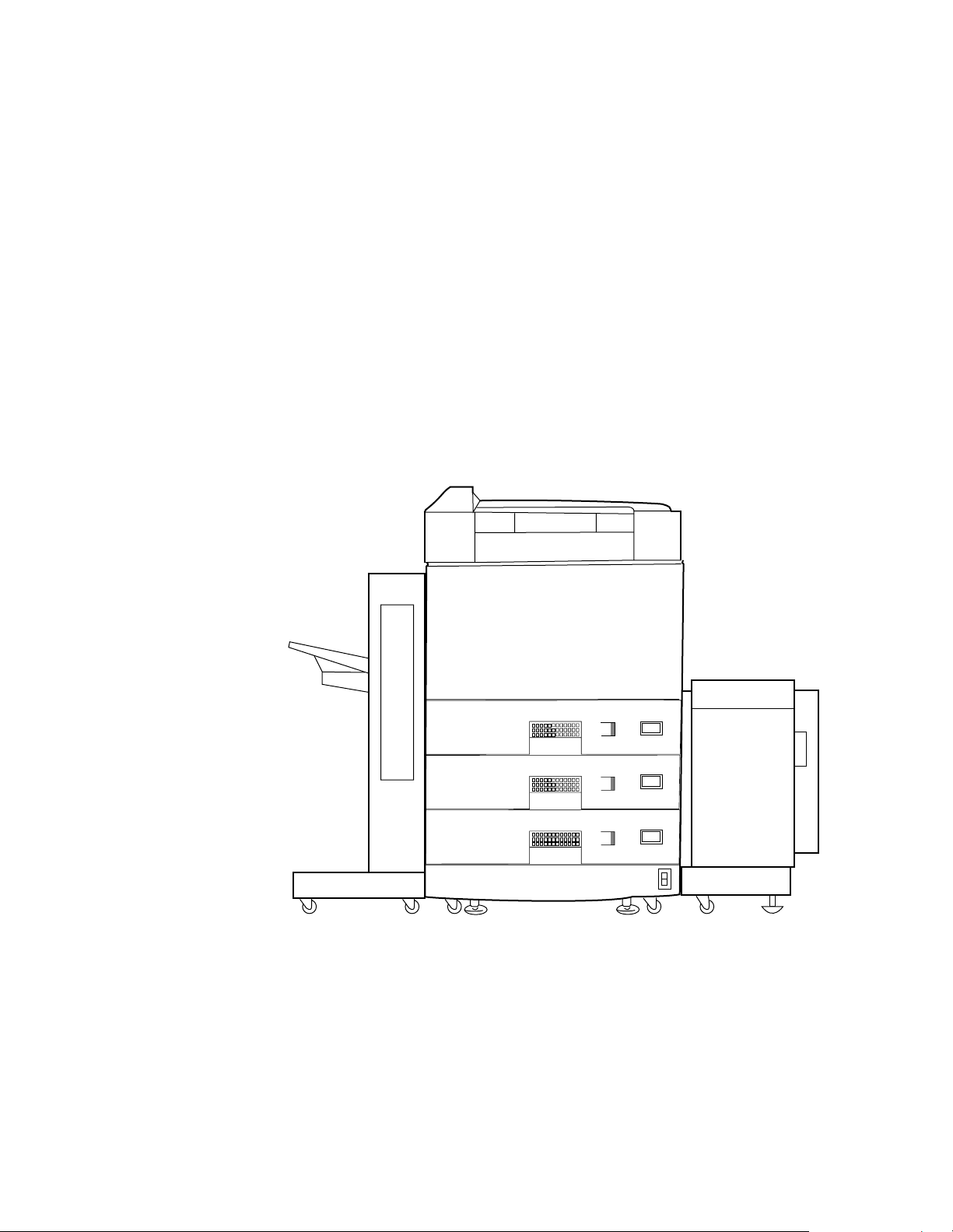
development process technology to print on cut-sheet plain paper. Figure 1-1 illustrates
an installed printer and the external high-capacity paper handling options.
D640 Printer Service Manual
LTR
LTR
LTR
HCO D640 HCI
Figure 1-1 D640 Printer With Optional High Capacity Input (HCI) and Output
(HCO) Paper Handlers
June 08, 1999 Specifications 1-3
Page 20

D640 Printer Service Manual
1-1.1 Related Documents
The following manuals are shipped with each printer and provide additional information
on the printer. The information in these manuals is not repeated in this manual.
D640 Printer Installation Manual
l
l
D640 Printer User Manual
l
D640 Technical Reference Manual
l
D640 Enhanced Features Manual
For more information about the D640 printer, see the following documents. Most of
these documents are available on the DLD-Cupertino web site (see 1-1.2 "Web Sites for
More Information," on page 1-5):
D640 Printer Installation Manual
l
Guides you through unpacking, setup, testing, and configuration of your printer.
D640 Printer User Manual
l
Contains the information needed by the customer to operate the D640 printer.
D640 Technical Reference Manual
l
Guide to using fonts and the PCL and PJL emulations on the D640. It also
documents additional aspects of printer usage in detail.
D640 Paper Specifications Guide
l
Guide outlines specifications for selecting print media appropriate for use in the
D640 printers.
3,000-Sheet HCO Installation and User Manual
l
D640 PostScript Emulation Manual
l
D640 Training Kit (Part # C5620-60010) contains:
l
• Maintenance Video Training Tape - NTSC (Part # C5620-90010)
• Maintenance Video Training Tape - PAL (Part # C5620-90011)
D640 Workbook
•
• Function Code Kit (Part # C5620-60021)
(Part # C5620-90012)
(Part # C5620-90015)
(Part # C5620-90024)
(Part # C5620-90002)
(Part # C5620-90001)
(Part # C5638-90001)
(Part # C5630-90002)
• D640 Printer Installation Manual
• D640 Printer User Manual
•
D640 Service Manual
Solutions Guide
l
Technical Data Sheet
l
D640 Demo CD-ROM
l
(Part #5966-7174)
(Part # 5965-7408)
(Part # 5966-4253)
1-4 Specifications June 08, 1999
Page 21

1-1.2 Web Sites for More Information
Web sites are available with updated information, such as updated manuals, alert
bulletins, software revisions, and technical support information. Many of the sites are
available to only internal HP employees.
Table 1-1. D640 Web Sites
D640 Printer Service Manual
Name
DLD-Cupertino Web
Site
DLD-Cupertino
Customer Web Site
German Response
Center
Global Support
Logistics - The Parts
Page
HP Internal/
External
HP internal http://itweb1.cup.hp.com/dld-cuprtino/
For updated version of this service manual:
1.Click DLD-Cupertino Document Database
2.Click Service Documents
3.Click HP D640
External http://partners1.americas.hp.com/spo/spodocpu.nsf/
WelcomeNavigator?OpenNavigator
HP internal http://grcad149.grc.hp.com/sys_prn
(The information is in German and English).
HP internal http://smomvts.rose.hp.com/
Access
June 08, 1999 Specifications 1-5
Page 22

D640 Printer Service Manual
1-2 Printer Specifications
This section provides general specifications for the printer, as well as detailed
specifications for print speed and the printer’s physical, electrical, and environmental
requirements. In addition, this chapter includes safety standards applicable to all
equipment and an illustration of the printer laser equipment warning label.
1-2.1 Printer General Specifications
Table 1-2 lists general specifications for the D640 printer.
Table 1-2. D640 Printer General Specifications
Item Specification
Printing technology Laser diode, Electro-photography
Printing speed 40 ppm (Letter/A4 landscape)
Paper
Resolution 600 x 600 dpi (selectable 100, 300, or 600 dpi)
Paper capacity
Stacker capacity
Emulation PCL, HEX, optional PostScript (PS)
Interface Parallel: IEEE1284C Bitronics/Centronics
Warm-up time Less than 150 seconds
First print time Less than 18 seconds
Resident RAM 16 MB standard/ 64 MB maximum
Resident font Bitmap font: 1, Outline fonts: 45
Size A3, A4, A5, Letter, Legal, Ledger, Exec utive, B4 (JIS), B5
(JIS), custom sizes
Type Plain paper, label paper, recycle paper, transparency paper,
bond paper, pre-punched paper
• 3 trays: 500 sheets (64 g/m2) standard
• High Capacity Input (optional): 3,000 sheets
(A4,Letter size only)
• Face down tray: 500 sheets each (75 g/m2)
• High Capacity Output (optional): 2,000 sheets or
3,000 sheets
Serial: RS232C/422A
1-6 Specifications June 08, 1999
Page 23
1-2.2 Printer Print Speed Specifications
The print speed specification for the D640 printer is 40 ppm (letter/A4 landscape).
Table 1-3. D640 Printer Print Speed Specifications
Paper Size (direction)
Letter (landscape) 40 40
Legal (portrait) 25 25
Ledger (portrait) 21 15
Executive (portrait) 40 40
A3 (portrait) 21 15
A4 (landscape) 40 40
A5 (portrait) 40 40
B4 (ISO) (portrait) 21 15
B5 (ISO) (portrait) 40 40
B4 (JIS) (portrait) 24 24
B5 (JIS) (portrait) 34 34
Custom
paper width = 120 mm to 297 mm,
paper length = 182 mm to 215.9 mm
Custom
paper width = 120 mm to 297 mm
paper length = 215.9 mm to 431.8 mm
a. Unit of measure: Images Per Minute (IPM). All the speeds have a ±5% tolerance
when printing 6000 characters-per-page using outline font of Courier 12 point
size. Print speed is measured beginning with the second page in continuous
printing mode.
Simplex
40 40
21 15
D640 Printer Service Manual
a
Duplex
a
1-2.3 Printer Physical Specifications
Table 1-4 lists the physical specifications of the printer. Figure 1-2 illustrates the physical
specifications and dimensions of the printer and Figure 1-3 illustrates the required
service area.
Table 1-4. D640 Printer Physical Specifications
Item Specification
Dimensions
Width 585 mm (23.0 in)
Depth 640 mm (25.2 in)
Height 1,03 0 mm (40.6 in)
Weight Approximately 135 kg
(297 lbs)
Service Area
Front 650 mm (25.6 in)
Back 850 mm (33.5 in)
Left 850 mm (35.5 in)
Right 850 mm (35.5 in)
June 08, 1999 Specifications 1-7
Page 24
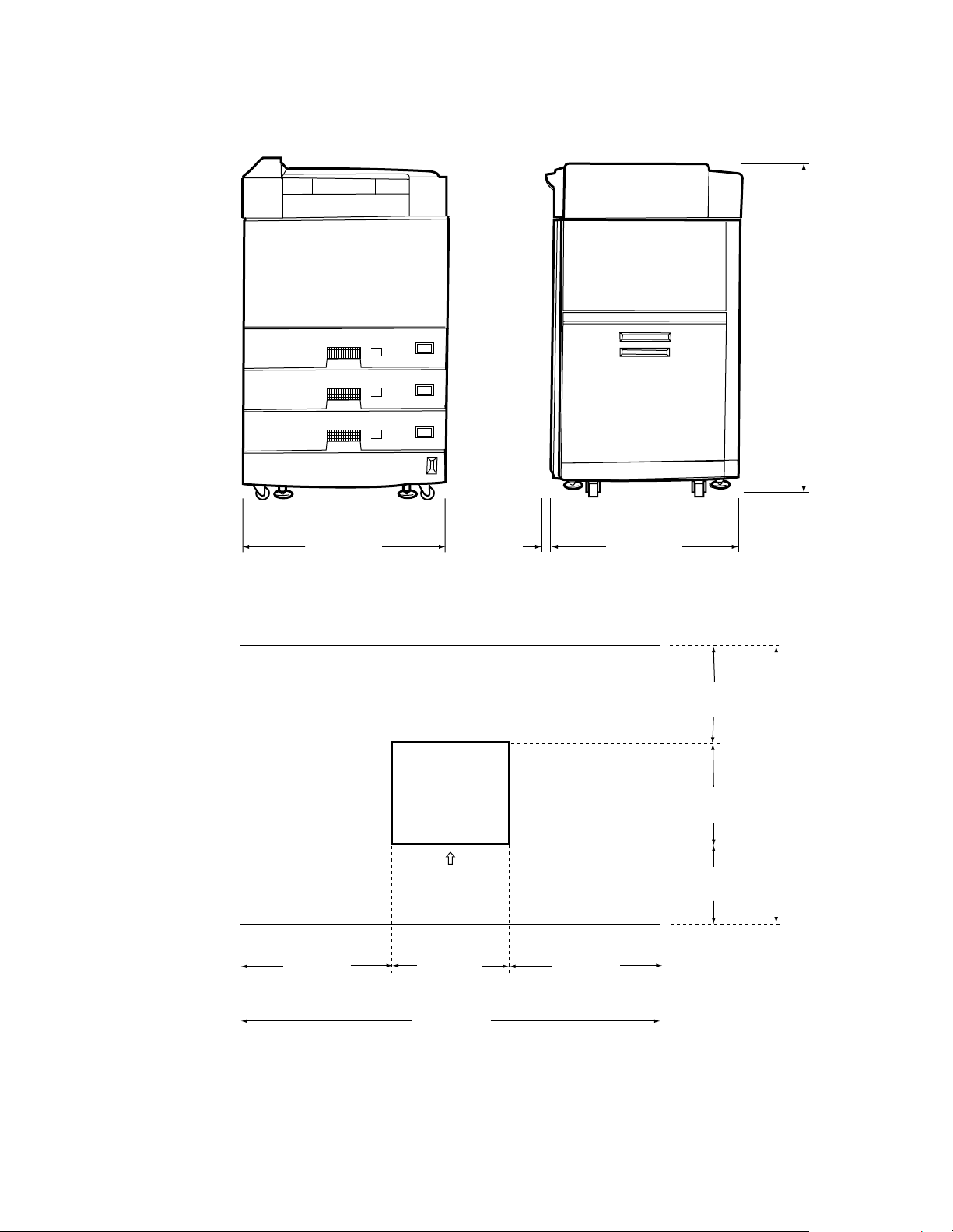
D640 Printer Service Manual
40.5 in.
LTR
LTR
LTR
(1030 mm)
23.0 in.
(585 mm)
1.38 in
(35 mm)
Figure 1-2 Printer Physical Dimensions
Printer
Front
Side
33.5 in.
(850 mm)
23.0 in.
(585 mm)
25.2 in.
(640 mm)
33.5 in.
(850 mm)
84.3 in.
(2140 mm)
25.2 in.
(640 mm)
25.6 in.
(650 mm)
33.5 in.
(850 mm)
90.0 in.
(2285 mm)
Figure 1-3 Required Service Area
1-8 Specifications June 08, 1999
Page 25
D640 Printer Service Manual
1-2.4 Printer Electrical Specifications
Table 1-5 lists the electrical specifications of the printer.
Table 1-5. D640 Printer Electrical Specifications
Item Specifications
Input Power
Voltage
Phase Single-phase
Frequency 50/60Hz ±5%
Power Consumption 1,300 VA or less during operating
Heat capacity 894 kcal per hour
120 to 127 Vac
200 to 240 Vac
±10%, 12 A
±10%, 7 A
1-2.5 Environmental Specifications For All Equipment
Table 1-6 lists environmental specifications applicable to the printer, High-Capacity Input
(HCI), and High-Capacity Output (HCO) units.
Table 1-6. D640 Printer, HCI Option, and HCO Option Environmental
Specifications
Item Specification
Acoustic noise 56 dB(A) or less (printer only)
Ozone emission 0.08 PPM or less: Measured under conditions of typical
printer operation and room ventilation
Operating Environment
Temperature 15° to 35° C
Humidity 20% to 80% RH (no condensation)
Temperature and humidity
gradients
Non-operating Environment
Temperature 0° to 35° C
Humidity 20% to 80% RH (no condensation)
Temperature and humidity
gradients
15° C per hour or less and 30% RH per day or less (no
condensation)
15° C per hour or less and 30% RH per day or less (no
condensation)
1-2.6 Printer Laser Equipment Compliance Label
This product is a Class 1 laser product.
CAUTION Use of controls or adjustment or performance of procedures other than those specified
herein may result in hazardous radiation exposure
Figure 1-4 illustrates the warning label located on the top of the optical unit.
June 08, 1999 Specifications 1-9
Page 26

D640 Printer Service Manual
DANGER
ATTENTION
VORSICHT
FARA
INVISIBLE LASER RADIATION WHEN OPEN AND INTERLOCK F AILED
OR DEFEATED.
AVOID DIRECT EXPOSURE TO BEAM
EXPOSITION AU LASER
INVISIBLE SI OUVERT OU SI LE
VERROUILLADE EST DEFECTUEUX EVITER
L’EXPOSITION DIRECTE AU RAYON DE
LASER.
UNSICHTBARE LASERSTRAHLUNG. WENN
ABDECKUNG GEOFFNET UND
SICHERHEITSVERRIEGELUNG UBERBRuCKT
NICHT DEM STRAHL AUSSETZEN.
Risk för stråining av osynilgt laserljus
om såkerhetsorytare är ur funktion då
tuckan öppnas.
Figure 1-4 Optical Unit Warning Label
1-3 Summary of Optional Features
Table 1-7 lists the options available with the D640 printer along with their associated HP
product numbers.
Table 1-7. D640 Printer Available Options
Item Specification Model Number
High-Capacity Input (HCI)
High-Capacity Output
3,000 sheets (at 75 g/m
2,000 sheets (at 75 g/m
(HCO)
3,000 sheets (at 75 g/m
Custom paper tray
500 sheets (at 75g/m
(100 x 182 to 297 x 431. 8 mm pape r
can be used)
PostScript upgrade PostScript Level 2 + 16MB Memory
SIMM
16 MB Memory Kit 16 MB SIMM (maximum 3 SIMMs) C5635A
2
)
2
)
2
)
2
)
C5621A (Letter)
C5622A (A4)
C5623A (120 VAC)
C5624A (240 VAC)
C5638A (100-240 VAC)
C5634A
C5630A
1-10 Specifications June 08, 1999
Page 27

1-4 Printer Custom Paper Tray
The C5634A custom paper tray is an optional, user-installable custom paper tray. The
custom paper tray can hold up to 500 sheets of paper (75g/m
custom paper trays are interchangable. If more than one custom tray is installed, all
custom sizes must be identical. Paper sizes for the custom tray are selectable within the
specifications listed in Table 1-8.
Table 1-8. Custom Paper Sizes
Dimension Minimum Maximum
Width 120 mm (4.75 in) 182 mm (11.7 in)
Length 297 mm (7.2 in) 431.8 mm (17 in)
The custom tray also supports all of the standard media sizes.
The print speeds from the custom tray are listed in Table 1-3.
1-5 PostScript Upgrade
D640 Printer Service Manual
2
). The standard and
The C5630A PostScript upgrade is an optional, user-installable, software upgrade that
adds PostScript Level 2 emulation capability to the D640 printer. This option is supplied
on a 3.5-inch floppy disk with an additional 16 MB memory SIMM, C5635A. Minimum
memory size to run the Postscript option is 32 MB.
1-6 16 MB Memory Kit
The optional C5635A 16 MB Memory Kit contains one 16 MB single-inline memory
module (SIMM) for the main controller of the D640 printer. A maximum of three
additional SIMMs can be installed. This option is user installable.
June 08, 1999 Specifications 1-11
Page 28

D640 Printer Service Manual
1-7 Consumables
Table 1-9 lists the specifications of the consumables used in the D640 printer and
optional High Capacity Input. For maximum print quality, ensure that the consumables
are replaced at the recommended intervals by monitoring the usage levels printed on
the first page of the Maintenance Report.
.
Table 1-9. Consumables and Replacement Cycle
Carton
Toner Kit 8-Pack C5626A Toner
Developer Kit C5632B Developer
Drum Kit C5629A Drum
Fuser
120-127Vac
Fuser
200-240Vac
Printer Pick Roller
Kit
HCI Pick Roller Kit C56 36B Pick Roller for HCI
a. Values for the replacement cycle shown in Table 1-9 are theoretical and based upon printing on l etter/
A4 size paper. Variations may occur due to improper handling, maintenance, media type, operating
environments and other factors related to printer usage.
b. The average for printed images is calculated by combining intermittent printing mode and continuous
printing mode. The result is 70% of continuous printing.
c. The drum counter increments every 150 seconds (this equals 100 images of letter/A4 paper during
continuous printing). This counter increments during warm-up and intermittent printing sequences.
d. The page length counter increments after 1 00 simplex letter/A4 images are stacked. During duplex
printing, the page length counter is incremented by two after 100 duplex images are stacked. For the
Printer Pick Roller Kit and the HCI Pick Roller Kit, this counter always increments as simplex printing.
When another size paper is used, the counter increments according to the values listed in Table 1- 10.
Product
Number Contents
8 bottles/carton
Cleaning Roller
4 /ctn.
Collector Bottle
8 bottles/carton
2 bottles/carton
Ozone Filter
1 unit/carton
1 unit/carton
Transfer Un it
1 unit/carton
Cleaning paper
10 sheets/carton
C5627A Fuser
1 unit/carton
C5628A Fuser
1 unit/carton
C5633A Pick Roller
1 set/carton
1 set/carton
Replacement Cycle
a
20K images for continuous printing
with 4% coverage for each bottle
(average 14.4K images)
b
Every other toner bottle
Every bottle of toner
1,600 drum counts for each bottle
(250K images for continuous
printing, average 114K images)
b
Every other bottle of developer
2,500 drum counts
c
(195K images for continuous
printing, average 178.5K images)
300K page length counts
d
500K page length counts each
Three kits required for ea ch printer;
one for each tray.
500K page length counts each
c
1-12 Specifications June 08, 1999
Page 29

Table 1-10. Page Length Count
Paper size Increment by 100 sheets
Simplex Duplex
A5
A4
A3
Letter
Legal
Ledger
Executive
B4 (JIS)
B5 (JIS)
1.5 3
1-8 Printable Area
You can print to the paper edge, but print quality is not guaranteed within 5 mm
(1/6 inch) of the paper edge. There is a file that can be printed from the printer’s hard
disk that show the guaranteed print image area for that media. Due to various media
factors (such as curl and grain) the guaranteed print image may vary slightly from the
specification.
D640 Printer Service Manual
12
12
24
12
24
24
12
24
To print a sample of the printable area for a type of media:
Step 1
Step 2
Step 3
Step 4
Place the media in the selected tray
Go to the Utilities menu (Test.filesC.MAINT.UTIL).
Select ALL_EDGE.22.
Select Online.
Attempting to print outside the printable area can cause the following problems:
Unacceptable print quality at paper edges
l
Paper feed skew (up to ±2mm) that may cause missing characters
l
Paper transport problems that may cause a paper jam
l
June 08, 1999 Specifications 1-13
Page 30
D640 Printer Service Manual
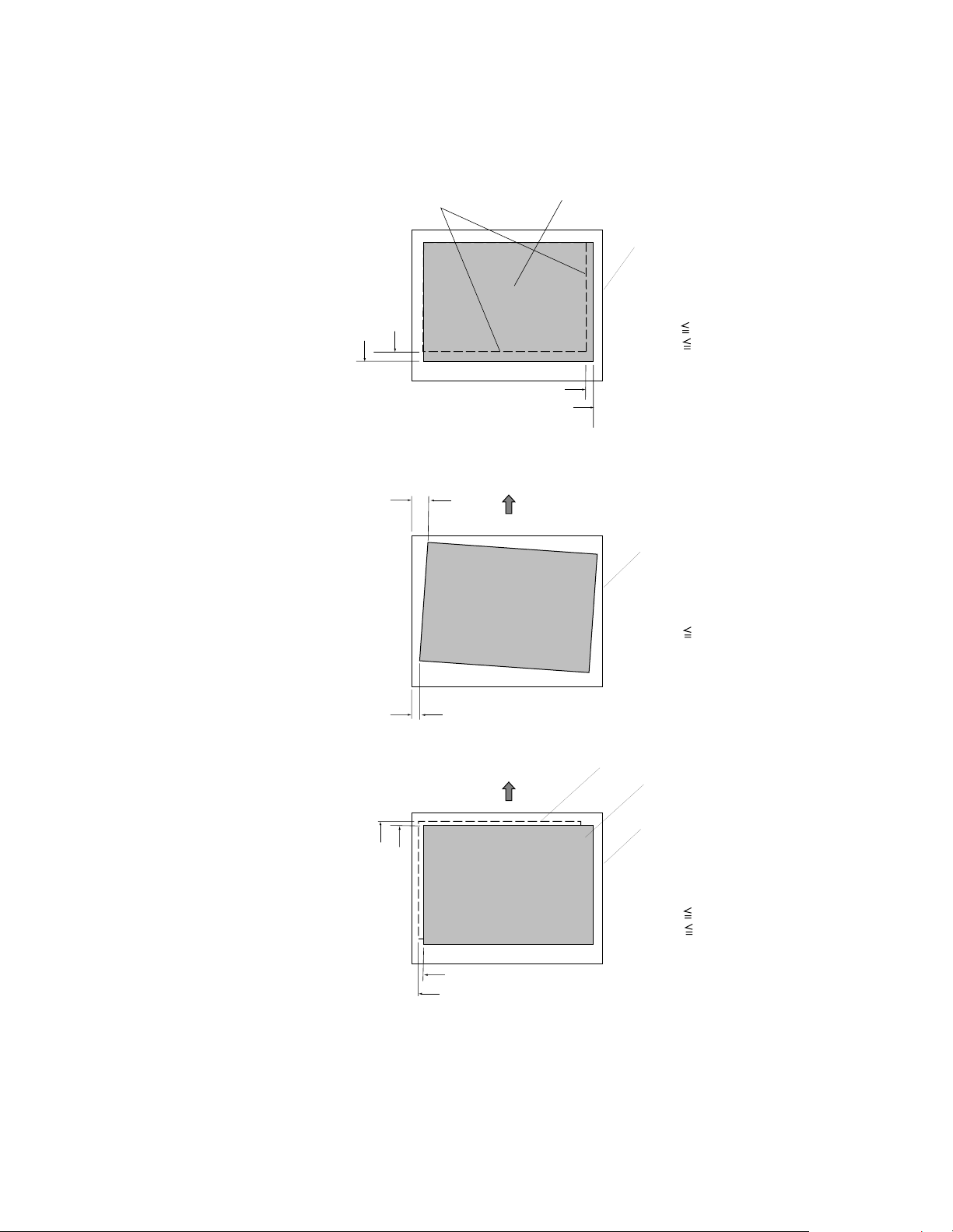
1-8.1 Printing Position Precision
Magnification
Skew
Ideal print area
H
I
A
Print area
Paper
| H-I | 2.5 mm
| J-K | 1.5 mm
J
K
Feed direction
Print section
Paper
| A-B | 2 mm over a length
of 432 mm
B
Feed direction
D
Front/Back
Image
Registration
E
F
G
Figure 1-5 Print Positions (page 1)
Back side image
Front side image
Paper
| D-E | 1.5 mm
| F-G | 1.5 mm
1-14 Specifications June 08, 1999
Page 31

D640 Printer Service Manual
Feed direction
A
Print section
B
Print area
Page Registration/
Margin Position
Figure 1-6 Print Positions (page 2)
1-8.2 Simplex and Duplex Printing
The following are important notes on simplex and duplex printing:
l
During
During
simplex
duplex
becomes the back side; the top side of the paper in the paper tray becomes the front
side.
The above is reversed when feeding from the High Capacity Input (HCI).
If punched paper is used for both simplex and duplex printing from the same paper
l
source, the holes and binding margin positions will not match.
If preprinted forms are used for both simplex and duplex printing from the same
l
paper source, the front and back of the preprinted forms and the printed data is
opposite for simplex or duplex paper.
When using punched paper or preprinted forms (directional paper) for simplex and
l
duplex printing from the
avoid these problems with punched or preprinted forms.
printing, the underside of the paper in the paper tray is the front side.
printing, the underside of the paper stacked in the paper tray
same
paper tray, specify duplex for all printing operations to
Paper
A = 4.2 mm ± 1.5 mm
B = 4.2 mm ± 1.5 mm
Upper tray
Simplex
Set the punched paper in the tray
around the other way
Lower tray
Duplex
Figure 1-7 Examples of Adding Paper to Paper Trays
June 08, 1999 Specifications 1-15
Page 32

D640 Printer Service Manual
1-16 Specifications June 08, 1999
Page 33

2
D640 Printer Service Manual
Functional Overview
Chapter 2 contents:
2-1 Introduction . . . . . . . . . . . . . . . . . . . . . . . . . . . . . . . . . . . . . . . . . . . . . . . . . . . .2-3
2-2 Physical Layout . . . . . . . . . . . . . . . . . . . . . . . . . . . . . . . . . . . . . . . . . . . . . . . . .2-3
2-2.1 Control Panel and External Front Cover . . . . . . . . . . . . . . . . . . . . . . . .2-4
2-2.2 Slots and Ports Accessible from Top Front Cover. . . . . . . . . . . . . . . . .2-5
2-2.3 Parts Accessible from the Front Door . . . . . . . . . . . . . . . . . . . . . . . . . .2-6
Knobs and Levers . . . . . . . . . . . . . . . . . . . . . . . . . . . . . . . . . . . . . . . . .2-7
2-2.4 Parts Accessible from the Top Cover and Ejection Cover. . . . . . . . . . .2-8
2-2.5 Parts Accessible from the Upper Right Cover. . . . . . . . . . . . . . . . . . . .2-9
2-2.6 Parts Accessible from the Lower Right Cover. . . . . . . . . . . . . . . . . . .2-10
2-2.7 External Parts Accessible from the Rear and Sides . . . . . . . . . . . . . .2-11
2-2.8 Parts Accessible from the Rear Cover . . . . . . . . . . . . . . . . . . . . . . . .2-12
2-2.9 High Capacity Input. . . . . . . . . . . . . . . . . . . . . . . . . . . . . . . . . . . . . . .2-13
2-2.10 2,000-sheet High Capacity Output . . . . . . . . . . . . . . . . . . . . . . . . . . .2-14
2-2.11 3,000 Sheet High Capacity Output . . . . . . . . . . . . . . . . . . . . . . . . . . .2-15
2-3 System Controllers, Control Panel, and Ports . . . . . . . . . . . . . . . . . . . . . . . . .2-16
2-3.1 Mechanism Controller . . . . . . . . . . . . . . . . . . . . . . . . . . . . . . . . . . . . .2-16
2-3.2 Main Controller . . . . . . . . . . . . . . . . . . . . . . . . . . . . . . . . . . . . . . . . . .2-19
Hard Disk Drive Organization . . . . . . . . . . . . . . . . . . . . . . . . . . . . . . .2-20
Floppy Disk Drive . . . . . . . . . . . . . . . . . . . . . . . . . . . . . . . . . . . . . . . .2-22
PCMCIA Slots . . . . . . . . . . . . . . . . . . . . . . . . . . . . . . . . . . . . . . . . . . .2-22
Serial Diagnostic Port . . . . . . . . . . . . . . . . . . . . . . . . . . . . . . . . . . . . .2-22
Serial and Parallel Ports . . . . . . . . . . . . . . . . . . . . . . . . . . . . . . . . . . .2-22
Data and Memory Processing. . . . . . . . . . . . . . . . . . . . . . . . . . . . . . .2-22
2-3.3 Control Panel . . . . . . . . . . . . . . . . . . . . . . . . . . . . . . . . . . . . . . . . . . .2-26
2-4 Power Supplies . . . . . . . . . . . . . . . . . . . . . . . . . . . . . . . . . . . . . . . . . . . . . . . .2-27
2-4.1 Low Voltage Power Supply . . . . . . . . . . . . . . . . . . . . . . . . . . . . . . . . .2-29
2-4.2 High Voltage Power Supply. . . . . . . . . . . . . . . . . . . . . . . . . . . . . . . . .2-32
2-4.3 Fans . . . . . . . . . . . . . . . . . . . . . . . . . . . . . . . . . . . . . . . . . . . . . . . . . .2-34
2-5 Developer and Toner Hopper. . . . . . . . . . . . . . . . . . . . . . . . . . . . . . . . . . . . . .2-35
2-5.1 Toner Hopper . . . . . . . . . . . . . . . . . . . . . . . . . . . . . . . . . . . . . . . . . . .2-35
2-5.2 Developer Unit . . . . . . . . . . . . . . . . . . . . . . . . . . . . . . . . . . . . . . . . . .2-36
2-5.3 Waste Toner . . . . . . . . . . . . . . . . . . . . . . . . . . . . . . . . . . . . . . . . . . . .2-37
2-5.4 Drive D Unit. . . . . . . . . . . . . . . . . . . . . . . . . . . . . . . . . . . . . . . . . . . . .2-37
2-5.5 Toner Messages . . . . . . . . . . . . . . . . . . . . . . . . . . . . . . . . . . . . . . . . .2-38
2-6 Electrophotographic Printing Process . . . . . . . . . . . . . . . . . . . . . . . . . . . . . . .2-39
2-6.1 Drum Unit . . . . . . . . . . . . . . . . . . . . . . . . . . . . . . . . . . . . . . . . . . . . . .2-43
2-7 Paper Path . . . . . . . . . . . . . . . . . . . . . . . . . . . . . . . . . . . . . . . . . . . . . . . . . . . .2-44
2-7.1 D640, HCI, and HCO Paper Feeding Motor Systems. . . . . . . . . . . . .2-45
2-7.2 Pick Motor System . . . . . . . . . . . . . . . . . . . . . . . . . . . . . . . . . . . . . . .2-46
2-7.3 Transport Motor System . . . . . . . . . . . . . . . . . . . . . . . . . . . . . . . . . . .2-46
June 08, 1999 Functional Overview 2-1
Page 34

D640 Printer Service Manual
2-8 Paper Feed and Transport from Trays and HCI . . . . . . . . . . . . . . . . . . . . . . . 2-52
2-9 Print Engine Feed Path and the Print Process . . . . . . . . . . . . . . . . . . . . . . . . 2-58
2-10 Ejection Path for Ejection Unit and HCO . . . . . . . . . . . . . . . . . . . . . . . . . . . . 2-68
2-7.4 Main Motor System . . . . . . . . . . . . . . . . . . . . . . . . . . . . . . . . . . . . . . 2-47
2-7.5 Reversing Motor System . . . . . . . . . . . . . . . . . . . . . . . . . . . . . . . . . . 2-48
2-7.6 Duplex Motor System . . . . . . . . . . . . . . . . . . . . . . . . . . . . . . . . . . . . 2-48
2-7.7 KMOT Motor System. . . . . . . . . . . . . . . . . . . . . . . . . . . . . . . . . . . . . 2-49
2-7.8 HCO Feed Motor System . . . . . . . . . . . . . . . . . . . . . . . . . . . . . . . . . 2-50
2-7.9 HCO Exit and Switchback Motor System . . . . . . . . . . . . . . . . . . . . . 2-50
2-8.1 Paper Tray Lift Process - Paper Trays. . . . . . . . . . . . . . . . . . . . . . . . 2-52
2-8.2 Paper Tray Lift Process - HCI . . . . . . . . . . . . . . . . . . . . . . . . . . . . . . 2-54
2-8.3 Paper Pick Process - Paper Trays. . . . . . . . . . . . . . . . . . . . . . . . . . . 2-55
2-8.4 Paper Pick Process - HCI . . . . . . . . . . . . . . . . . . . . . . . . . . . . . . . . . 2-56
2-8.5 Transport Feed Path - Paper Tray and HCI. . . . . . . . . . . . . . . . . . . . 2-57
2-9.1 Engine Feed Path . . . . . . . . . . . . . . . . . . . . . . . . . . . . . . . . . . . . . . . 2-58
2-9.2 Paper De-Skewing Process. . . . . . . . . . . . . . . . . . . . . . . . . . . . . . . . 2-59
2-9.3 Paper Input Shift . . . . . . . . . . . . . . . . . . . . . . . . . . . . . . . . . . . . . . . . 2-61
2-9.4 Image Transfer and Drum/Paper Separation. . . . . . . . . . . . . . . . . . . 2-62
2-9.5 Fuser Unit . . . . . . . . . . . . . . . . . . . . . . . . . . . . . . . . . . . . . . . . . . . . . 2-63
2-9.6 Decurler Unit . . . . . . . . . . . . . . . . . . . . . . . . . . . . . . . . . . . . . . . . . . . 2-64
2-9.7 Reversing Unit. . . . . . . . . . . . . . . . . . . . . . . . . . . . . . . . . . . . . . . . . . 2-65
2-9.8 Duplex Unit . . . . . . . . . . . . . . . . . . . . . . . . . . . . . . . . . . . . . . . . . . . . 2-66
2-10.1 Ejection Unit and Top Bin . . . . . . . . . . . . . . . . . . . . . . . . . . . . . . . . . 2-68
2-10.2 2000-Sheet High Capacity Output. . . . . . . . . . . . . . . . . . . . . . . . . . . 2-69
2-10.3 3,000-Sheet High Capacity Output . . . . . . . . . . . . . . . . . . . . . . . . . . 2-70
2-2 Functional Overview June 08, 1999
Page 35

2-1 Introduction
This chapter provides the theory of operation of the D640 including the following:
Overview of the physical layout of mechanical components
l
Detailed descriptions of the following:
l
• paper path
• electrophotographic printing process
•controllers
• power supplies
• toner and developer units
2-2 Physical Layout
This section describes the physical layout of the printer identifying the major
components.
D640 Printer Service Manual
LTR
LTR
LTR
HCO D640 HCI
Figure 2-1 HP5000 D640 and Optional High Capacity Input and High Capacity
Output
June 08, 1999 Functional Overview 2-3
Page 36

D640 Printer Service Manual
2-2.1 Control Panel and External Front Cover
The control panel contains the following operator controls and display:
Standby power switch
l
Liquid crystal display
l
Five buttons that operate menu functions within the display
l
Light emitting diode (LED) that indicates that the printer is in the power-save mode.
l
Speaker
(Not used)
Front cover
Front door
Tray1
Tray2
Tray3
LCD Panel
.
.
.
.
.
.
.
.
.
.
.
.
.
.
.
.
.
.
Function buttons
Ejection unit
....
.
.
.
.
.
.
.
.
.
.
.
.
..
Power Save Mode Indicator
Standby switch
Screen contrast control
Paper output tray
Upper right cover
Lower right cover
Paper level indicators
Paper size indicators
Main power switch
Figure 2-2 Control Panel, Tray, and Cover Location
2-4 Functional Overview June 08, 1999
Page 37

D640 Printer Service Manual
2-2.2 Slots and Ports Accessible from Top Front Cover
The top front cover allows access to the following slots and port:
• Two PCMCIA slots
• Serial diagnostic port
• Floppy disk drive slot
PC (PCMCIA) card slots
(Protective rubber cap installed.
Connector for factory testing only)
Serial diagnostic port
(Used for factory testing only)
Floppy disk drive
(3.5 inch, 1.4 MB FDD
for updates to function code
and field diagnostics)
Figure 2-3 Upper Front Cover
Front cover
....
.
.
.
.
.
.
.
.
.
.
.
.
.
.
June 08, 1999 Functional Overview 2-5
Page 38

D640 Printer Service Manual
2-2.3 Parts Accessible from the Front Door
The front door allows access to the following:
Va rious knob s and lev er s
l
Fuser unit
l
Drum unit
l
Transfer Assembly Guide
l
Decurler unit
l
....
.
.
.
.
.
.
.
.
.
.
.
.
.
.
Fuser unit
locking knob
Drum unit
locking knob
Reversing unit lever
Decurler knob
Decurler lever
Fuser roller separation lever
Duplex unit
Duplex unit knob
Transfer guide handle
Cleaning roller
Transfer assembly guide
Duplex guide lever
Fuser
Drum
Registration roller knob
Developer release lever
Lever stop screw
Transport
roller knob
LTR
Figure 2-4 Front Inside View
2-6 Functional Overview June 08, 1999
Page 39

D640 Printer Service Manual
Knobs and Levers
The following knobs and levers are available:
Developer release lever—Moves the developer unit when replacing the drum.
l
Developer release lever operating position is vertical. When the developer release
lever is turned to the stop screw, the developer drive coupling on drive M unit moves
away from the developer drive gears, allowing the developer to move away from the
drum. When the stop screw is removed, the developer release lever can be turned
to the right 90°, allowing the developer unit to be removed or inserted into the
printer.
Transport roller knob—Turns the transport roller (counter-clockwise) advancing
l
media away from PS2.
Registration roller knob—Turns the registration rollers (clockwise) advancing media
l
away from PS3.
Decurler roller knob—Rotates the rubber paddle rollers advancing media away from
l
PS4 in the decurling assembly.
Fuser roller separation lever—Separates the fuser rollers so that media can be
l
removed.
Reversing unit lever—Spring-loaded upwards to hold media in the reversing unit.
l
Pull down on this lever to gain access to any media that may be contained in the
reversing unit.
Decurler lever—Spring-loaded upwards to hold media in the decurler unit. Pull down
l
on this lever to gain access to any media that may be contained in the decurler unit.
Duplex unit knob—Advances media through the duplexer and PS5.
l
Transfer guide handle—Pull to release the transfer assembly guide.
l
Duplex guide lever—Lift to access paper in the duplex unit. The lever is held in
l
place by a magnet located in the base of the duplex unit.
June 08, 1999 Functional Overview 2-7
Page 40

D640 Printer Service Manual
2-2.4 Parts Accessible from the Top Cover and Ejection Cover
The following parts are accessible by opening the ejection cover and removing the top
cover:
Main controller
l
• Hard disk drive
• Floppy drive
• SIMMs
Optical unit
l
Paper
Main controller
inside of housing
Ejection cover
Located under top cover
....
.
.
.
.
.
.
.
.
.
.
.
.
.
.
Figure 2-5 Printer Top and Upper-Right Side View
Optical unit
2-8 Functional Overview June 08, 1999
Page 41

D640 Printer Service Manual
2-2.5 Parts Accessible from the Upper Right Cover
The following parts are accessible by opening upper right cover:
Developer unit
l
Toner hopper
l
....
.
.
.
.
.
.
.
.
.
.
.
.
.
.
Toner collector bottle
Developer collector bottle
Toner hopper
Developer unit
Figure 2-6 Right Cover Access View
Upper right cover
June 08, 1999 Functional Overview 2-9
Page 42

D640 Printer Service Manual
2-2.6 Parts Accessible from the Lower Right Cover
The three paper feed units are accessible by opening lower right cover. The paper feed
units contain the following for each tray:
Paper pick rollers
l
Separation rollers
l
Paper out sensor (EMPSEN)
l
Pick roller up sensor (LEVSEN)
l
Paper feed sensor (PS1-1/2/3)
l
Figure 2-7 Printer Lower-Right Side View
Upper paper feed unit
Middle paper feed unit
Lower paper feed unit
2-10 Functional Overview June 08, 1999
Page 43
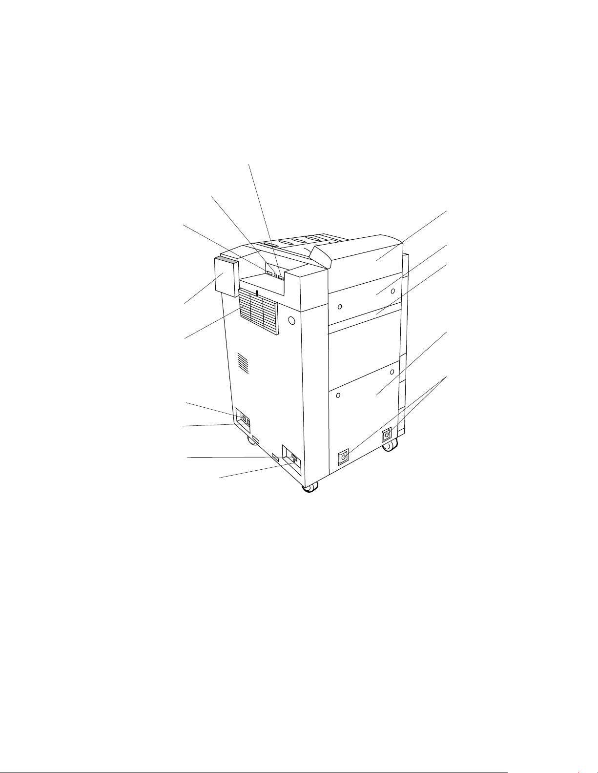
D640 Printer Service Manual
2-2.7 External Parts Accessible from the Rear and Sides
The following parts are accessible from the left side and rear of the printer without
removing or opening cover.
Serial port (RS232/422)
Switches used for factory
testing only
Parallel port
(IEEE 1284C)
User documentation
holder
Ozone filter
HCI I/F connector
Printer input
power connector
HCO I/F connector
Ejection unit
Upper left cover
Removable HCO cover
Lower left cover
HCO
attachment
points
Lower connector
not used
Figure 2-8 Printer Rear and Left-side View
June 08, 1999 Functional Overview 2-11
Page 44
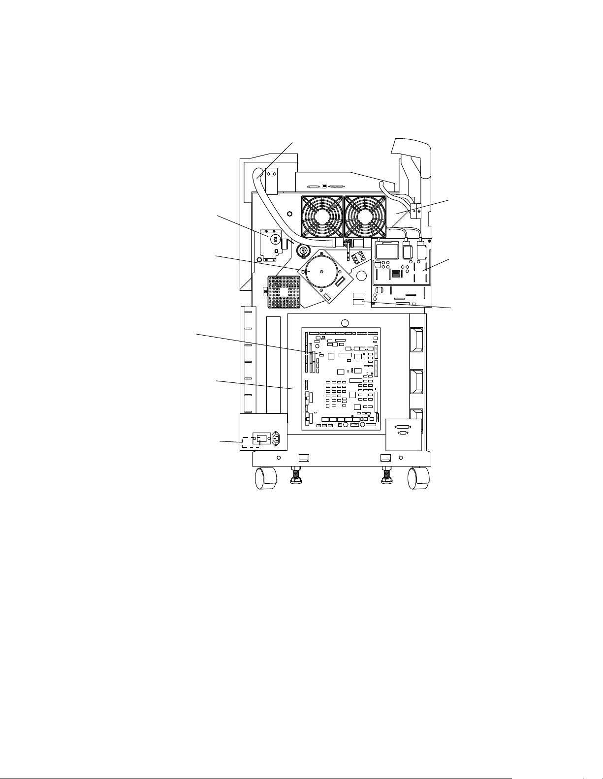
D640 Printer Service Manual
2-2.8 Parts Accessible from the Rear Cover
The following parts are accessible by removing the rear cover.
Drive unit D
Waste toner auger
Drive unit E
Drive unit M
Mechanism
controller
board
Low voltage
power supply
(LVPS)
(Behind mechanism
controller board)
Paper transfer
motor (behind
bracket)
Figure 2-9 Printer Inside Rear View
High voltage
power supply
(HVPS)
Power save
relays
2-12 Functional Overview June 08, 1999
Page 45
2-2.9 High Capacity Input
The optional 3000 sheet capacity High Capacity Input is powered directly from the
printer. The C5621A supports Letter size paper and the C5622A supports A4 sized
paper only. The only difference between these HCI models is the placement of the front
and rear paper guides.
Printer
D640 Printer Service Manual
HCI release handle
Paper lowering button
HCI door
Figure 2-10 High Capacity Input
Door handle
Paper table
(inside door)
June 08, 1999 Functional Overview 2 -13
Page 46
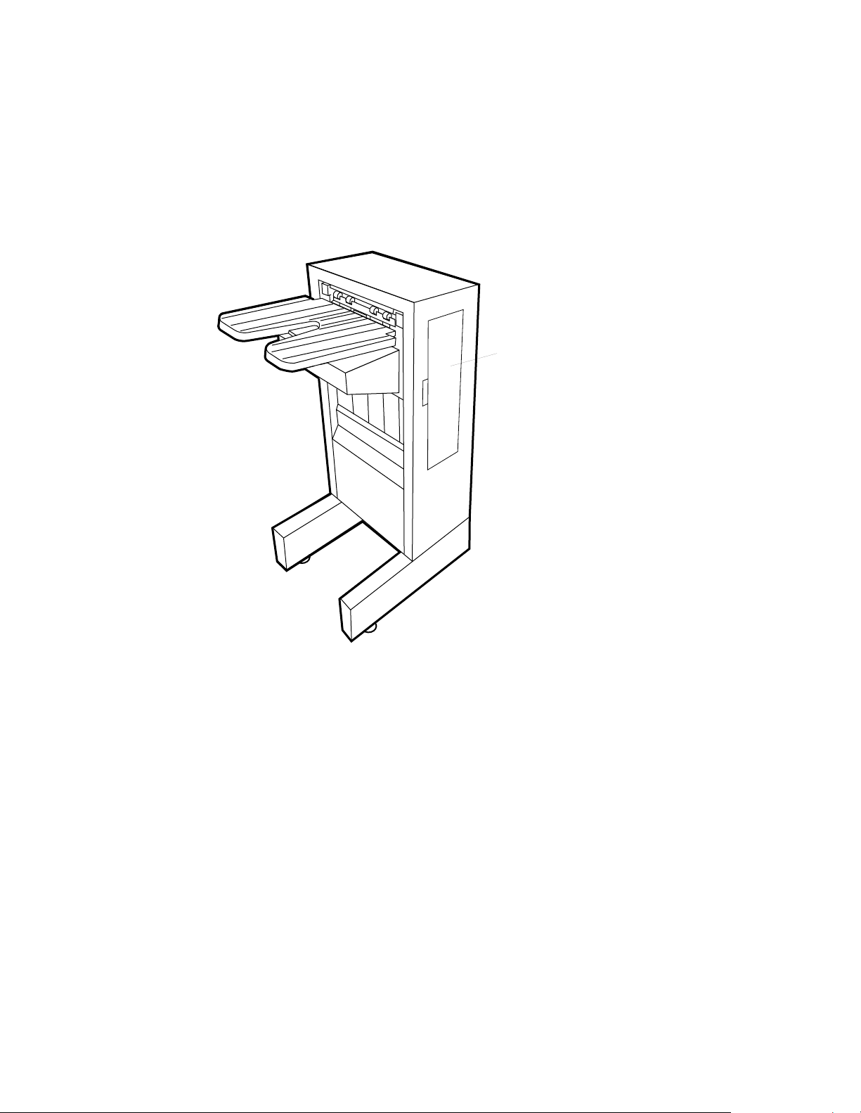
D640 Printer Service Manual
2-2.10 2,000-sheet High Capacity Output
The 2000 sheet HCO handles all the paper sizes supported by the printer. There are two
models to handle two different power requirements, 120-127 VAC and a 200-240 VAC.
The only difference is the internal power supply. The HCO has a separate AC power
cord.
Access door
Figure 2-11 2,000 Sheet High Capacity Output
2-14 Functional Overview June 08, 1999
Page 47
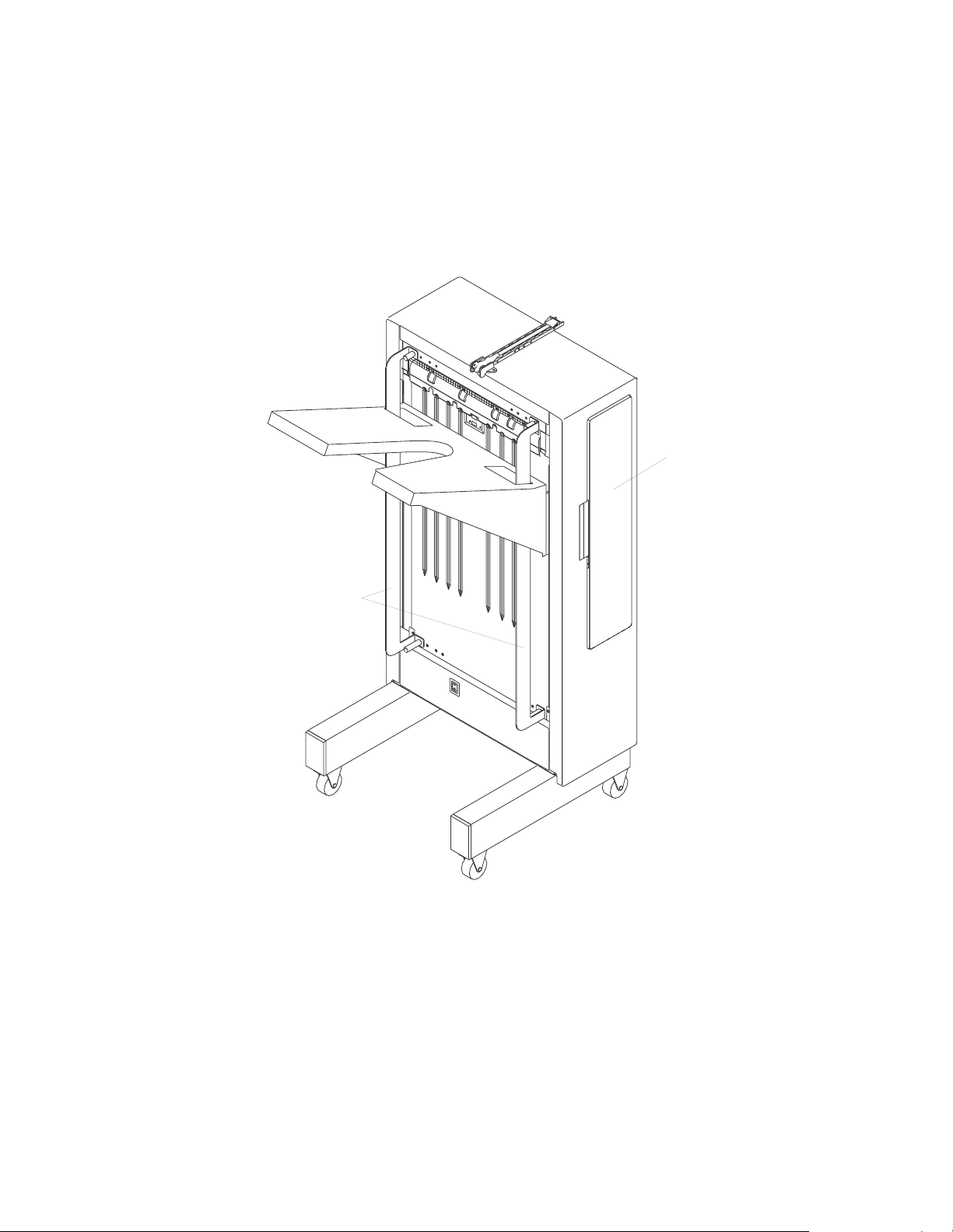
2-2.11 3,000 Sheet High Capacity Output
The 3,000 sheet HCO handles all the paper sizes supported by the printer. There are
two models to handle two different power requirements, 120-127 VAC and a 200-240
VAC. The only difference is the internal power supply. The HCO has a separate AC
power cord.
D640 Printer Service Manual
Access door
Paper guides
Figure 2-12 3,000 Sheet High Capacity Output
June 08, 1999 Functional Overview 2 -15
Page 48

D640 Printer Service Manual
2-3 System Controllers, Control Panel, and Ports
There are two controllers in the printer that control all internal and external functions, the
mechanism controller and the main controller. The operator and service engineer
communicate with the printer through the control panel and the ports.
2-3.1 Mechanism Controller
The mechanism controller contains the control circuits for all of the motors, optical unit,
high-voltage power supply, solenoids, and clutches within the printer.
The master and slave firmware on the mechanism controller contain timing algorithms
for every supported paper size. These algorithms dictate when the motors, solenoids,
and registration clutch should be turned off or on. The mechanism controller constantly
monitors all of the paper sensors in the printer and halts all motors, solenoids, and
clutches if a sensor is activated outside of the allowable parameters for the media size
being transported. If a sensor is activated outside of the allowable parameters, the
mechanism controller sends a status byte to the main controller for interpretation; the
main controller then posts the appropriate message on the control panel (for example,
Paper Jam).
The mechanism controller sends the Video Request (VR) signal to the main controller
when it is ready to print. The optical unit sends the Video Sync (VS) signal to the
mechanism controller to start printing.
The mechanism controller has an NVRAM (EEPROM) chip that maintains the total page
count, current consumable counts, and electronic paper alignment values when power
is off. If the mechanism controller is replaced, this 8-pin socketed integrated circuit
must always be transferred to the new mechanism controller to maintain these counts.
The board also contains switches to control settings and run diagnostics. The Test
Switch (S3) is located in the top right of the installed board. When the printer is ready,
you can press this switch to generate a test printout. This test printout completely
bypasses the main controller. The lower-right corner of the board contains three multiposition DIP switches. When you replace the mechanism controller, these switches
must be set to match the old board. For a complete description of the switches and their
settings, see 5-2.2 "Mechanism Controller Board Switches," on page 5-7.
2-16 Functional Overview June 08, 1999
Page 49

D640 Printer Service Manual
Slave
EPROM
Pin 1
(Test switch)
Pin 1
+5V
W7
SW3
W5 (TNDNS)
Master
EPROM
NVRAM
(EEPROM)
SW4
SW1
DIP switches
SW2
Figure 2-13 Mechanism Controller Chips, Switches, and Test Points
June 08, 1999 Functional Overview 2 -17
Page 50
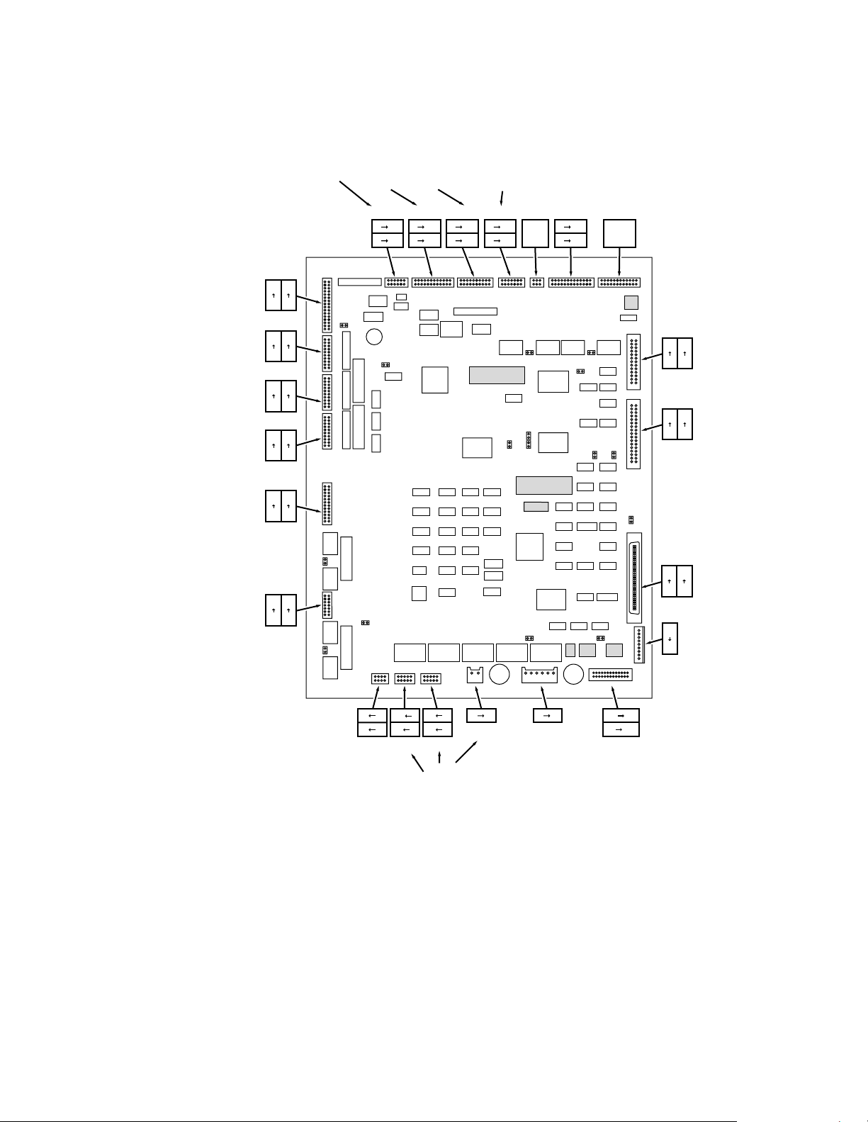
D640 Printer Service Manual
toner & developer
Developer/
toner hopper/
drive D
Feed unit 1
Feed unit 2
Feed unit 3
Input tray
closed
microswitches
Transport
feed & lift
motors
Erase LED/
PS2, 3, 4/
sensors
CN1
32
31
2
1
CN2
19
20
2
1
CN3
19
20
2
1
CN4
19
20
2
1
CN5
23
24
2
1
CN6
14
13
2
1
Fans
CN23
1 11
2 12
Fuser/
main motor
CN22
CN21
1 23
1 19
2 24
2 20
Duplex
unit
CN20
1 13
2 14
Solenoids,
reversing
unit motor
CN19
CN18
Not
1 25
Used
2 26
CN17
Not
Used
CN16
25
26
1
2
CN15
33
34
1
2
CN14
68
34
1
35
CN13
1
External
9
connector
HVPS
Optical
unit
Main
controller
8 2
7 1
CN7
HCI
10 2
9 1
CN8
10 2
9 1
CN9
LVPS
1 2
CN10
1 6
CN11
Optical unit/
LVPS
14 26
1 13
CN12
HCO
Figure 2-14 Mechanism Controller Connectors
For a list of the connectors and a detailed description, see Table 5-2. "Mechanical
Controller Connectors," on page 5-53.
2-18 Functional Overview June 08, 1999
Page 51

2-3.2 Main Controller
The main controller is a printed circuit board with the hard disk and 3.5" floppy disk drive
directly mounted onto the board, but separately replaceable.
The main controller contains:
Motorola 68040 (40 MHz) processor
l
Operator control panel int erf ace
l
Serial and IEEE1284 parallel interface controllers and connectors
l
16 MB of on-board RAM memory
l
Three additional slots for optional 16 MB SIMMs
l
Two Type III PCMCIA slots
l
Date and time clock with a surface mounted lithium battery (10+ year life)
l
8 KB NVRAM that stores all setup report configuration values and event log
l
2 MB of ROM that contains PCL and Postscript fonts
l
4 MB Flash memory, which holds
l
• Bank 0—Printer’s function code
• Bank 1—Postscript (optional) and internal diagnostics (two separate programs)
• Banks 2 and 3—User downloads, such as fonts and macros
D640 Printer Service Manual
The main controller receives data via the serial or parallel interface ports, the PCMCIA
slots, the hard disk, or the floppy disk. The main controller uses the data to format the
page and then convert the page into dot rows. When the mechanism controller asserts
the VR (Video Request) signal, the main controller sends the dot row data to the optical
unit.
The main controller maintains the control panel. The menus are stored in the main
controller code and most selections are saved in the main controller NVRAM. The main
controller receives error messages from the mechanism controller in Hex format and
converts and displays them in alphanumeric format.
The power-on switch (part of the control panel) is simply a ground signal that is routed
through the main controller, mechanism controller, and the low-voltage power supply.
Powering down from the switch activates a sequence so that the last sheet is fully
printed and ejected before the printer power is turned off. This is a firmware-controlled
sequence by the main controller and mechanism controller.
The four position DIP switch between the serial and parallel connectors should
be set to the UP position so that the printer can boot up by loading the function code
from bank 0 of the main controller’s flash memory. Changing the settings of this switch
will allow the main controller to initialize from alternate locations in flash. For a
description of the DIP switch settings, see 5-2.1 "Main Controller Board DIP Switches,"
on page 5-6.
always
June 08, 1999 Functional Overview 2 -19
Page 52

D640 Printer Service Manual
SIMM
expansion
slots
Motorola 68040
processor with
attached
cooling fan
2 PCMCIA
card slots
CN16
Figure 2-15 Main Controller Board
CN15
IEEE1284
(Type C)
Parallel port
DIP Switches
(Factory diagnostics)
RS232/422
Serial port
Real time
clock and
battery
Floppy disk drive (bottom)
Hard disk drive (top)
Hard Disk Drive Organization
The internal hard disk contains several directories and files that can be helpful when
servicing the printer. The disk is organized similar to a DOS file system, with a volume
label (for example, E01V04), directories, subdirectories, and files.
Some of the directories on the hard disk are the following:
USER_ADJ—Contains the file Alignset.33 that is used to electronically align the
l
print image from the
MAINT—Contains several subdirectories as follows:
l
• CE_PROG contains the following two subdirectories:
A backup copy of the Printer Diagnostic Program—Selecting the file (for
example, CE980131.LE3) and placing the printer on-line copies the Printer
Diagnostic Program into the main controller’s flash memory (bank 1) where it
can be executed. If the diagnostic program is not resident in flash and loading is
attempted, the control panel (including the standby power switch) will lockup. In
this case, power off the printer at the main power switch on the lower right front,
power on the printer, and copy the backup copy of the diagnostic program from
the hard disk to the main controller flash (see 3-1.3 "Loading or Upgrading the
Printer Diagnostic Program," on page 3-4).
every
Paper Path T est—Prints 180 sheets from
every
with paper loaded) to
available output bin (upper bin or HCO). Used to
verify entire paper path (see 4-2 "Troubleshooting Overview," on page 4-6).
ready paper source (tray or HCI
2-20 Functional Overview June 08, 1999
Page 53

D640 Printer Service Manual
• FUNCODE contains the following two subdirectories:
MAIN—Contains a backup copy of every function code that has been installed
on the printer (for example, 02V01L52.S, where .S is the current version and
.OLD is a previous version).
PS—Contains a copy of the printer’s optional Postscript code (for example,
961121.S). PS subdirectory will be empty if the Postscript option was not
purchased and installed from a floppy disk
• UTIL contains several files:
LASERSET.
unit. This file will print a pattern which can then be used to change Switchbank 2
on the mechanism controller to adjust the laser start position (see 5-3.3 "Laser
Start Position Alignment," on page 5-10).
ALL_EDGE.
media. This pattern will show how close to the media edge printing can be done
on any particular media before print quality problems are evident.
FILECHK.PCL—Checks the directory structure of the hard disk and attempts to
repair any problems it has found. Similar to the Scandisk utility on a PC, this file
will print a report of any problems this utility was unable to fix.
CAPTURE.100mb—Sets a 100-Mbyte limit for capturing files on the printer’s
hard disk. This is the default for a captured file.
CAPTURE.1_4mb—Sets a 1.4-Mbyte limit for capturing files on the printer’s
hard disk. This utility is useful for creating small capture files to copy to the
printer’s floppy disk.
EVENTLOG.C2A (C: to A:)—Performs the following sequence
-prints a Maintenance Report
-updates the EVENTLOG.PCL file on the printer’s hard disk
-copies the file to the floppy disk.
Insert a blank, formatted floppy disk before selecting.
REPORTS & EVENTLOG.C2A—A utility t hat
xx
—Used to adjust the laser start position after replacing the optical
xx
—Prints an edge-to-edge, front-and-back pattern on the installed
-prints a Setup and Maintenance Report
-copies a print file of the Setup Report and the Maintenance Report to
floppy disk
-copies the eventlog.pcl file to floppy disk.
This utility is useful for sending complete information to support personnel for
analysis. Insert a blank, formatted floppy disk before selecting.
• EVENTLOG.PCL—Prints the complete eventlog from the hard disk. On function
code L52 or later, whenever the Maintenance Report eventlog is 50% full, it is
copied to this file (or appended to this file if already present on the hard disk) so
that a complete error history is maintained on the hard disk for the printer.
Version L03 or later, the eventlog is copied whenever a Maintenance Report is
printed.
June 08, 1999 Functional Overview 2 -21
Page 54

D640 Printer Service Manual
Floppy Disk Drive
The 3.5 inch, 1.4 MB floppy disk drive is used to load the optional Postscript emulation
code and update the printer’s function code. Appropriately formatted files may also be
printed directly from a disk, and files can be stored to a floppy disk using the Capture
utility (Menu.Maintenance.capture.)
PCMCIA Slots
The two PCMCIA card slots can be used by support personnel and by our customers,
but they are officially not supported or documented by HP. The PCMCIA slots can be
used for following:
Factory level diagnostics contained on flash PCMCIA
l
Specific linear flash cards (Maxtor, KingMax, and Intel) that are transparent to the
l
user and could be used if a customer wanted to make their non-standard font the
default
Third party developers/OEMs for specific applications, such as TROY Systems, that
l
use the PCMCIA slot for MICR fonts and signatures. This allows the special fonts/
signatures to be removed and stored in a more secure environment between usage
PCMCIA ATA hard disk drives (Maxtor, Integral Peripherals). These PCMCIA hard
l
drives act as drive B (upper PCMCIA slot) or drive D (lower PCMCIA slot).
Serial Diagnostic Port
The RS-232 serial diagnostic port on the front of the printer directly connects a personal
computer to the printer. From the computer display, you can dynamically view printer
operating system commands and registers. The control panel communications menu
allows you to configure the baud rate, parity, start and stop bits for the front serial
diagnostic port and the rear 25-pin serial port simultaneously. This port is rarely used
except for factory level testing.
Serial and Parallel Ports
The rear serial port supports RS232 or RS422 serial host communication and the IEEE
1284C parallel port supports bidirectional parallel or standard Centrontics parallel
communication. The printer will automatically switch between the serial and parallel port
as data is presented by the host computers (Hot Port Switching).
Data and Memory Processing
The printer main controller is basically a small computer that performs the central
communication with the other printer systems, such as the mechanism controller, and
optical unit.The communication between the main controller and mechanism controller
is bi-directional. The mechanism controller communicates with the optical unit for status
and timing synchronization.
PCL, PJL, HP-GL/2, PS, TIFF, and VIP are types of data format that are accepted by the
printer. PCL, PJL, HP-GL/2, and PS are printer languages that generate binary data the
printer understands. The information about the data types are contained in the
beginning section (data stream) of the data file. TIFF (Tagged Image File Format) is data
format generally used for graphic images.
2-22 Functional Overview June 08, 1999
Page 55

D640 Printer Service Manual
VIP (Video Image Printing) is the raster data stream generated by the main controller
and sent to the optical unit turning the laser on and off to create the printing image on
the drum.
Figure 2-16, Figure 2-17, and Figure 2-18 show the interaction between the main
controller, mechanism controller, and the optical unit.
Data
Main Controller Board
Device bus (16 bit)
Yes
MOPY?
Yes
Hard disk drive
spools and
sends VIP data
Convert VIP data to video data
(using highspeed compression/decompression
VLSI–decompression step)
VIP Data?
No
Yes
No
Auto-emulation switching
(determines if PCL, PS, or TIFF)
Convert data to VIP format
(using highspeed compression/decompression
VLSI and M68040 processor–compression step)
No
Ready to
send data?
(Check status of optical
unit and mechanical
controller)
Status line
Video
Data
Optical Unit
Status line
Status line for
timing and synchronizing
Mechanical
Controller
Board
Figure 2-16 Job Processing
June 08, 1999 Functional Overview 2 -23
Page 56

D640 Printer Service Manual
Data
Main Controller
Accept data
(Input buffer)
Check data type
(PS or PCL)
Convert data to RIP
(VIP format)
Compess job pages
for jam recovery
Check status of
mechanism controller
& optical unit
Decompress VIP data
into video raster data
for the optical unit
Status &
print control
commands
Mechanism Controller
Accept data
(Video I/F control)
Check printer
engine status
Check optical
unit status
Status OK
(Inform main
controller
Status lines for timing
Status line
and sychronization
between print engine and data
Status line
Optical Unit
Video data
Figure 2-17 Main Controller Data Flow
2-24 Functional Overview June 08, 1999
Page 57

June 08, 1999 Functional Overview 2 -25
DRAM
0
1
Figure 2-18 Printer Page Buffer
10
11
12
13
14
15
16
2
3
4
5
6
7
8
9
Page RAM
image area
14MB
14
15
16
"Free RAM"
(Macros, download
fonts, work, etc.)
Input buffer
(16K default 1 000K (max.)
63
64
64MB DRAM Max.
Page RAM example:
A3 size duplex job @ 600 dpi
DRAM Page RAM
0
A3 size (side 1)
uncompressed
8MB maximum
8
Unused page
buffer RAM
14
Side 2
Compression
(convert to VIP)
Additional DRAM added
via the SIMM slots
Data
Side 1
Compression
(convert to VIP)
DRAM Page RAM
0
2MB (side 1) in VIP
2
2MB (side 2) in VIP
4
Unused page
buffer RAM
14
Input
Buffer
DRAM Page RAM
0
2MB (side 1) in VIP
2
Unused page
buffer RAM
14
Decompression
(VIP to video)
Side 1
Data processed
into uncompressed
image data
0
2
10
14
Video
data
Repeat for side 2
DRAM Page RAM
2MB (side 1) in VIP
A3 size (side 2)
uncompressed
8MB maximum
Unused page RAM
Optical
Unit
D640 Printer Service Manual
Page 58

D640 Printer Service Manual
2-3.3 Control Panel
The control panel contains the following operator controls and display:
Standby power switch
l
Liquid crystal display
l
Five buttons that operate menu functions within the display
l
Light emitting diode (LED) that indicates that the printer is in the power-save mode.
l
The LCD panel is always backlit except when in power-save mode. The internal speaker
on the control panel is not used. The control panel connects directly to the main
controller via the cable in rear of the panel.
The main power switch acts as a circuit breaker controlling the 120/240 VAC power to
the printer and is usually left on. To turn operational power on or off, use the standby
power switch on the control panel. The standby power switch is a software controlled
switch that only powers off the printer after all paper has cleared the paper path.
LCD Panel
.
.
.
.
.
.
.
.
.
.
.
.
.
.
.
.
.
.
Speaker
(Not used)
Function buttons
Figure 2-19 Control Panel
Power Save Mode Indicator
Standby switch
Screen contrast control
2-26 Functional Overview June 08, 1999
Page 59
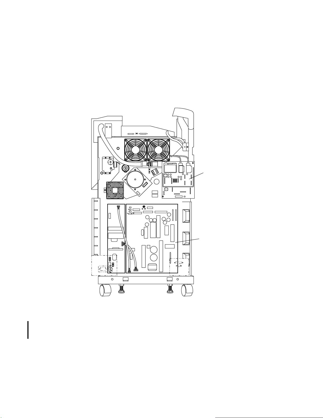
2-4 Power Supplies
Printer power is generated from two main power supplies, the low voltage power supply
(LVPS) and the high voltage power supply (HVPS). These power supply boards contain
the individual power supplies that generate voltage for all the systems on the printer.
The power supplies are accessible from the rear of the printer. The LVPS is behind the
mechanism controller board.
D640 Printer Service Manual
High voltage
power supply
(HVPS)
Low voltage
power supply
(LVPS)
(Behind mechanism
controller board)
CB1
Figure 2-20 Power Supplies Location
The main power switch (circuit breaker) controls the 120/240 Vac power to the printer,
and is usually left on. When turned on, the main power switch supplies AC power to the
low voltage power supply . The standby power switch operates as a firmware controlled
switch that only powers off the printer after the final sheet has cleared the paper path.
(For the power on sequence timing diagram, see A-4 "Power-on Sequence Timing
Chart," on page A-28.)
June 08, 1999 Functional Overview 2 -27
Page 60
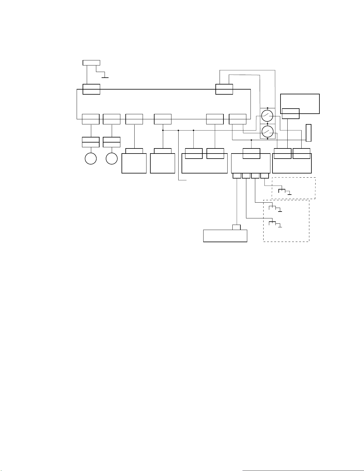
D640 Printer Service Manual
ACIN
CNFAN2
CNFAN2J
(Fig. A-1)
(Fig. A-1)
AC1J
ACIN
FAN5P
FAN5J
FAN
5
FG
CNFAN1
CNFAN1J
FAN4P
FAN4J
FAN
4
(Fig. A-1)
CN6
DCNJ6
OPPJ
OPERATOR
PANEL
LV POWER SUPPLY
CN7
DCNJ7
(Fig. A-2)
HDDJ
HDD
CNJ14
CN14 CN01
MAIN CONTROLLER
+12V
(Fig. A-22)
(Fig. A-18)
(Fig. A-2)
DCNJ10
CN10
CN5
DCNJ5
MCNJ1
DEVELOPING UNIT
DCNJ3
CN3
+12V
+5V
+24V
DNDC
CNDC
HV POWER SUPPLY
VB
ACH +HV -HV
VB
OPTICAL UNIT
CN4
RL2
RL1
(Fig. A-2)
TRANSFER CHARGER UNIT
SPJ4
+5V
(Fig. A-2)
CNJ11
CN11
MECHANISM
CONTROLLER
FG
TRANSFER
CHARGER
FG
AC CHARGER
FG
+12V
DRUM
PRE-CHARGER
(Fig. A-2)
(Fig. A-2)
CNJ10
CN10
LH24J
HCI
Figure 2-21 Power Distribution
2-28 Functional Overview June 08, 1999
Page 61
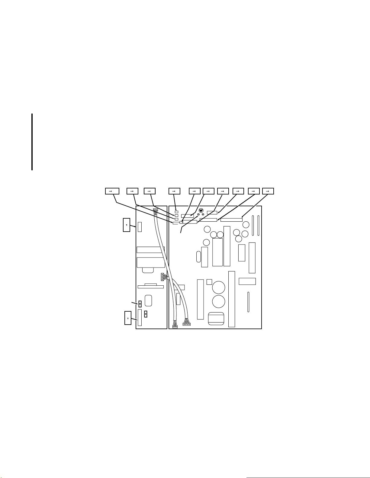
2-4.1 Low V oltage Power Supply
The low voltage power supply (LVPS) supplies +5 (+4.82), +12 and +24 Vdc power to all
devices within the printer and the optional high capacity input (HCI). The LVPS has two
alarm LEDs visible through a hole in the top center above the mechanism controller:
Left LED indicates a DC voltage fault labeled POWALM
l
Right LED indicates a Fan 4 and/or 5 failure labeled FANALM.
l
In normal operation, both of these alarm LEDs are off. If either LED is lit, the fault
causing the lighted LED must be corrected. To turn off the LED:
Correct the fault causing the lighted LED
1
Unplug the printer from the power source or turn off the main power switch
2
Wait until the LED turns off (about 15 seconds)
3
Plug in the printer and turn power on.
4
D640 Printer Service Manual
CN4
3
1
CB2
ACIN
1
6
CNFAN1CN10CN1
1 31 21 10
CB1
CNFAN2
1 3
CN2
1 2
+5V adjust
and LEDs
CN8
1 4
CN7
1 4
CN6
1 3
CN5
1 5
CN3
1 8
Figure 2-22 Low Voltage Power Supply
The only adjustable LVPS voltage is the +5Vdc, adjusted to 4.82 (±0.02Vdc) to comply
with the “Energy Star” requirements. The 4.82Vdc is measured at Test Point W7 on the
mechanism controller. The +5V adjust is available through an access hole on the
mechanism controller bracket (see Figure 2-11). If the +5Vdc is adjusted too low, the
printer malfunctions and the control panel is blank, poorly lit, too bright, or has missing
characters. If the +5V is adjusted too high, the control panel is blank except for a
horizontal white line.
June 08, 1999 Functional Overview 2 -29
Page 62

D640 Printer Service Manual
+5V adjust
(RV113)
POW ALM
(Power alarm LED)
FAN ALM
(Fan alarm LED)
TRM1
TRM2
WDG
TCS
W6
WCG
SG
WAG
SG
SG
Low voltage power
supply board
SW3
TRM4 TRM3
WBG
SG
BDRDY
W1
TNDNS
W5
MWTRES
LDP1
W2
W3
BD
W4
+5V
WEG
W7
SG
Low voltage power
supply access hole
Mechanism
controller board
Bracket supporting
mechanism
controller board
+5V (W7)
test point
Figure 2-23 LVPS +5V Test Point W7 and +5V Adjustment
The L VPS block diagram (see Figure A-23 "Low Voltage Power Supply Block Diagram,"
on page A-24) shows the path the AC power takes to become the DC voltage used by
the printer. The following is the sequence:
The incoming AC power (ACIN) from the main power switch routes through either
1
the two safety circuit breakers (CB1 and CB2) on the low voltage supply. These
circuit breakers check for serious problems within the LVPS and if tripped, replace
the LVPS.
AC power routes through noise filters either directly to the fuser or to internal LVPS
2
circuits that detect 120 Vac or 240 Vac and monitor for inadequate voltage, and a
power factor correction (PFC) circuit (required for European Standard EN61000-3-2
to reduce harmonic distortion in the neutral return).
The AC power is rectified into DC power and routed to the +5, +12, and +24 Vdc
3
power supplies.
2-30 Functional Overview June 08, 1999
Page 63
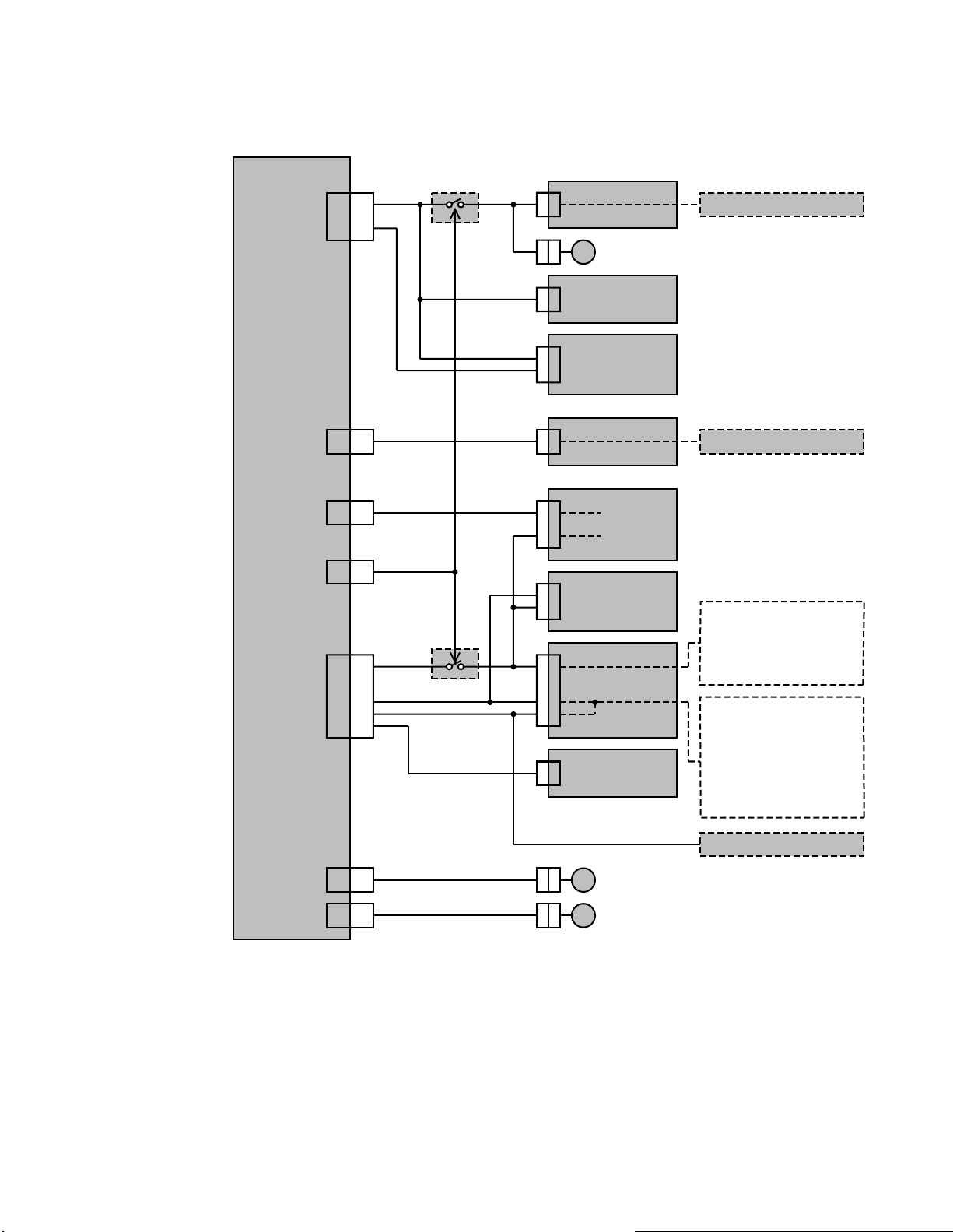
Power supply unit
CN7
+12V
+5V
RL2
Mechanism controller
CN10
FAN6
Main controller
CN14
Hard disk drive
HDDJ
D640 Printer Service Manual
Toner density sensor
CN5
CN6
CN10
CN3
+5V
+5V
+5V
+5V
+24V
+24V
+24V
RL1
Main controller
CN1
Control panel
(logic circuit)
(back light)
OPPJ
Optical unit
CN4
Mechanism controller
CN11
HV power supply
CNDC
Floppy disk drive
• PS1 to PS7
• Stack full sensor
• Paper empty sensors
• Paper level sensors
• Toner discharging screw sensor
• Logic circuit for main motor
• Toner empty sensor
• Pick motors
• Lift motors
• Feed motor
• Main motor
• Duplex motor
• Reversing motor
• Stacker select solenoid
• Purge solenoid
• Toner motor
• Developer discharge shutter motor
• Fan1 to 5 and 7
(HCI)
CN3
CN3
FAN4
FAN5
Figure 2-24 LVPS Distribution
June 08, 1999 Functional Overview 2 -31
Page 64

D640 Printer Service Manual
The three DC voltages supplied by the LVPS route to the following areas:
+5 Vdc (+4.82 Vdc)
l
• Logic
•Sensors
• Mechanism controller logic
+12 Vdc
l
•RL2
• Fans
• Mechanism controller
• Main controller
• Hard drive
+24 Vdc
l
•Motors
• Solenoids
• Fans
• High voltage power supply
• HCI
• Optical unit (via the mechanism controller)
The +5 Vdc picks relays RL1 and RL2 (on the frame; not on the LVPS) and routes to the
main controller. RL1 and RL2 are the “power save” relays. When power save mode is
active, RL1 cuts off the +5 Vdc to the control panel backlight, the optical unit, and the
mechanism controller, and RL2 cuts off the +12 Vdc to the mechanism controller.
If the low volatage power supply detects a speed problem in Fan 4, Fan 5, or any +5,
+12 or +24 Vdc loads, the power ready signal drops and the LVPS shuts down. The
LVPS has two alarm LEDs visible through a hole in the metal mounting plate at the top
center of the mechanism controller. The FANALM LED illuminates if the low voltage
power supply detects a problem in Fan 4 or Fan 5. (Fan 4 is the fuser exhaust fan and
fan 5 is the low voltage power supply cooling fan located on the rear lower frame.) The
POWALM LED illuminates if the mechanism controller detects an over current in the +5,
+12, or +24 Vdc loads connected to these power supplies.
2-4.2 High Voltage Power Supply
The high voltage power supply (HVPS) provides high voltages to the following:
l Precharger in the drum (-HV)
l Developer for its developer bias voltage (VB)
l Transfer and separation chargers (+HV)
l Separation voltage for charger (ACH)
The HVPS is firmware controlled by the mechanism controller and powered by 24V from
the low voltage power supply. No measurements or adjustments can be made on the
board.
2-32 Functional Overview June 08, 1999
Page 65

D640 Printer Service Manual
AC separation
Developer bias
on mechanism
ACH
voltage
VB
To CNIG
controller
-HV
Precharger
+HV
Transfer charger
+24 Vdc
from LVPS
Figure 2-25 High Voltage Power Supply
The high voltage supply uses the +24 Vdc directly from the low voltage supply to
generate four separate high voltages used in the electrophotographic printing process.
Within the high voltage supply assembly, there are four separate power supplies. For
block diagrams for each of the four power supplies, see A-3 "Printer Power Diagrams,"
on page A-24.
-HV —Generates 1.2 KVdc for the precharger in the drum. The -HV cable connects
l
to a lever spring within drive M unit on the rear printer frame. A metal contact at the
top rear of the drum contacts this lever spring conducting the -HV voltage to the
precharger corona in the drum. After passing through a grid between the precharger
and the drum, -600 Vdc is placed onto the drum surface by the precharger corona.
When the drum is removed the lever spring is visible on the rear printer frame. A
contaminated precharger or a drum that will not accept a charge (end of life) can
cause a failure (due to arching) to be detected by the -HV supply error circuitry.
-VB —Generates -350 Vdc for the developer bias voltage applied to the developer
l
mixture. The -VB cable connects the HVPS board to a connector directly to the
lower left of the high voltage supply. The connector connects to another cable
running to a connector directly below the waste toner bottle, where a cable from the
developer unit is inserted to complete the circuit. There is no direct feedback from
the developer unit to the high voltage developer bias supply. This cable can be
disconnected for troubleshooting purposes, but the white areas of the page will gray.
l ACH—Generates high AC voltage for the separation charger. The ACH cable
connects to the high voltage supply through a hole in the printer rear frame and
connects to the transfer assembly guide. The separation charger utilizes the same
ground wire as the transfer charger to complete the circuit.
l +HV—Generates high positive voltage to the transfer charger. The +HV cable
connects to the high voltage supply through a hole in the printer rear frame to the
transfer assembly guide. A green ground wire connects the metal plate on the lower
side of the transfer unit assembly to the printer frame to the left of the HVPS to
June 08, 1999 Functional Overview 2 -33
Page 66

D640 Printer Service Manual
complete the circuit. The metal plate under the transfer/separation charger must
solidly contact the frame of the charger or intermittent transfer or separation
problems will be experienced, such as SVC 6F errors.
Each of the four separate supplies has an error detection circuit that reports to the
mechanism controller, which sends the appropriate status byte to the main controller.
Should an error be detected on one of the internal high voltage supplies, an SVC 6F
High Voltage Error (see 4-9.19 "SVC 6F High Voltage Power Alarm," on page 4-52) is
posted on the control panel. An open or shorted charger, high voltage supply or ground
will be detected as an error.
2-4.3 Fans
Six fans cool the printer. Fan 3 is not needed and was removed from later printers. Fan
3 error detection is inoperable on the earlier printers when using the current firmware.
Fans 1, 2, and 7 are 24 Vdc. When an interlock opens, all 24 Vdc fans stop. Fans 4, 5,
and 6 are 12 Vdc. When an interlock opens, all 12 Vdc fans continue to turn.
Fans 2 and 4 have an ozone filter. The ozone filter is a consumable and is packaged
with the developer kit. The ozone filter should be replaced every other time the
developer bottle mixture is replaced.
Fans 1, 2, 6, and 7 have sensors that determine if the fan is rotating and can be used for
troubleshooting (see 3-13.6 "Fan Sensors Screen (EngMaint.Sensors.FAN)," on
page 3-26). If these fans are not rotating, a SVC alarm is indicated on the control panel
(see 4-9.22 "SVC A0 In-Frame Fan Alarm 1," on page 4-60 or 4-9.23 "SVC A1 Fan
Alarm 2," on page 4-62).
If fans 4 or 5 stop rotating, the printer power halts and the Fan Alarm LED (FAN ALM) on
the LVPS board lights (see Figure 2-23).
Fan 4
Fan 2
Fan 3
(see Note 3)
Fan 7
Fan 5
Fan 6
Fan 1
Notes:
1. All 24V fans stop when any interlock
switch is opened.
2. All 12V fans continue running regardless
if any interlock switch is opened.
3. Fan 3 was removed on later model printers and
does not operate with current firmware.
4. Fan assignments are:
Fan Voltage Purpose
1 24V Cool optical unit
2 24V Cool main frame
3 24V Cool main motor
4 12V Cool fuser
5 12V Cool LVPS
6 12V Cool main controller board
7 24V Cool main frame
Figure 2-26 Fan Locations
2-34 Functional Overview June 08, 1999
Page 67
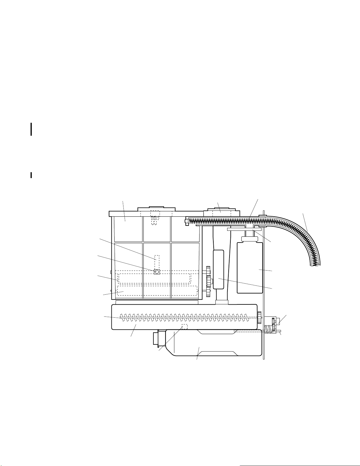
2-5 Developer and Toner Hopper
The developer unit contains developer mixture and toner used by the printer to write on
the surface of the drum and transfer to the paper. Both the developer mixture and toner
are consumables that must be periodically replaced or replenished.
2-5.1 Toner Hopper
The toner hopper holds the toner supplied to the developer unit. Toner is added through
the toner fill cap on top of the hopper. The hopper holds less than two bottles of toner.
Never fill more than one bottle of toner at a time or toner hopper spillage or clogging can
When the first bottle of toner is added in an empty hopper, you need to run about
result.
3,000 pages before the toner low message appears and you can add one more bottle of
toner to fill the hopper. If the level is above the sensor, there is not enough room for a
complete bottle. Foam on the top of the hopper covers holes that allow air displacement
from the hopper during the toner loading process. When an add toner message
displays, adding of toner logs an entry in the maintenance log. A bottle of toner typically
lasts approximately 18,000 images at 4% coverage.
D640 Printer Service Manual
Sensor wiping
arm
Ultrasonic
sensor
Toner agitation
arm
Toner dosage
roller
Developer
augers
Toner hopper
Developer
Magnetic
sensor
Developer fill
tube
Developer waste bottle
Waste toner auger
Waste toner hose
Recycling
shutter
Waste toner
bottle
Toner hopper
motor
Drive D unit
Developer
shutter
Figure 2-27 Toner/Developer System
An ultrasonic sensor, mounted on the inside of the hopper, detects low toner level. The
sensor sends out an ultrasonic signal and monitors the strength of the return signal to
determine if the hopper needs toner added.
June 08, 1999 Functional Overview 2 -35
Page 68

D640 Printer Service Manual
The toner hopper motor, mounted on the outside of the hopper, turns the toner dosage
roller and a shaft with the toner agitation arm and ultrasonic sensor wiping arm. The
rotating w iper arm ke eps the t oner from stic king to th e sen sor. On the same shaf t as the
wiper arm, a rotating toner agitation bar stirs the toner to keep the toner free-flowing.
The dosage roller meters toner into the developer. This roller has a pocked surface that
measures out a specific amount of toner each revolution. The sensor is checked every
0.5 seconds and the toner motor is activated for 0.5 second intervals when the
developer’s magnetic sensor indicates that toner is needed in the developer.
2-5.2 Developer Unit
The developer unit holds the developer and toner mixture (see Figure 2-27).
As part of the developer purge process, developer is poured into the fill cap of the
developer tube that connects directly into the developer unit. Developer flows directly
into the auger area where augers move in opposite direction to mix the developer and
toner metered in from the dosage roller meters. The developer and toner are mixed and
agitated during the completion of the developer purge process.
Figure 2-28 Developer Augurs and Rollers
The developer unit contains a magnetic sensor to measure the electrical properties of
the developer mixture (3.5% toner and 96.5% carrier). The mechanism controller uses
this sensor to compensate for developer mixture aging by altering the toner ratio present
never
in the developer unit. For this reason,
printer without first purging and replacing new developer mixture. The developer mixture
has a life up to 160,000 drum rotations. The printer will stop at 150% of life span of
developer mixture (function code Revision E02L03 or later).
The toner density sensor detects the percentage of toner in the developer by measuring
the magnetic flux in the developer/toner mixture. As more toner is added the voltage
goes down; as the print process uses toner the voltage increases. The mechanism
controller maintains the correct density by monitoring the output of the sensor and
adding toner as necessary during the printing process.
2-36 Functional Overview June 08, 1999
use a developer assembly from another
Page 69

At the end of the developer mixture install process the sensor is calibrated by the
mechanism controller to measure +2.5 Vdc at TNDNS. This assumes developer was
added that 3.5% toner by weight (a new bottle). Over the life of the developer mixture,
the mechanism controller gradually increases in steps the voltage to the input of the
sensor. As the sensor input voltage increases so does the output voltage. The
monitoring circuit sees this increase as reduced toner and adds more to bring the
sensor level back down, thus increasing the amount of toner in the mix.
The new developer mixture is 3.5% toner, 96.5% carrier by weight. Over the first 100
pages, the printer adds enough toner to bring the mixture up to 4.5%. Over the life of the
developer mixture, the mixture is increased to 5.5%. This increase is necessary as the
developer gradually loses its ability to attract toner to the carrier particles. The printer
displays a developer replacement message at 160,000 rotations. The printer stops at
240,000 rotations.
Toner is only loaded during the printing process. If power save is disabled, it is possible
to deplete the toner from the developer causing a low density error.
2-5.3 Waste Toner
Toner waste hose/auger (see Figure 2-27) carries waste toner directly from the waste
collector of the drum assembly to either the waste toner bottle or recycles it back to the
toner hopper. Waste toner includes paper particles and any other material scraped off
the drum. The toner kit supplies one empty waste toner bottle for every bottle of toner.
D640 Printer Service Manual
Drive M unit drives the waste toner auger, a long-spring auger that transports waste
toner up to the waste toner bottle. The waste toner auger is a separate part and not part
of drive M unit.
If the toner recycling shutter is enabled, waste toner goes back into the toner hopper
and not into the waste toner bottle.
print quality occurs and is not recommended for optimal print quality .
be enabled in three ways:
Sliding the shutter to close the mouth of the waste toner bottle
l
Removing the waste toner bottle
l
Allowing the waste toner bottle to fill up
l
Toner recycling adds 15% to 20% to toner life, but decreases quality slightly over a long
period of time. If quality decreases below desired level, a developer purge will quickly
clear the problem.
The waste toner bottle sensor shown in this picture is no longer installed and is ignored
by the firmware if installed.
2-5.4 Drive D Unit
Drive D unit (see Figure 2-27) drives the developer shutter assembly. The shutter
assembly opens during the developer bottle mixture replacement cycle. The shutter
opens to allow the old developer mixture to move into the waste developer bottle for
disposal.
If toner recycling is turned on, a slight degradation of
T oner recycling can
June 08, 1999 Functional Overview 2 -37
Page 70

D640 Printer Service Manual
2-5.5 Toner Messages
The following are some of the toner messages that can occur:
Toner Low - Toner below the toner sensor.
l
Toner Empty - Toner needed by the developer. Voltage at TNDNS rising and no
l
toner at the toner sensor. Stops the printer and is not resetable
Toner Hopper Alarm - Toner needed by the developer but no toner dropping and a
l
toner present indication by the toner sensor. Possibly caused by a non-rotating
dosage roller or tightly-packed toner. Stops the printer but is resetable: press Clear
or cycle power.
Toner Low Density Alarm - The developer density sensor has gone outside its
l
operating range. This alarm can only be recovered from by purging the developer or
adding toner to the developer.
2-5.6 D640 Density Level Settings (and Engine Limits)
The VB and Laser Power values that are related to the Density 1-15 values are stored
the mechanism controllers Master EPROM. The laser-power value is changed from the
Density setting in the Density menu (Menu.Maintenance.Density).
VB (Developer Bias) voltages greater (more positive) than -300 Vdc (-299 and up) the
carrier beads will ’bleed’ out from the developer unit onto the drum and into the paper
path.
“Density”
Value
1 -300.78 0.2205 Minimum
10 -351.00 0.3000 Factory Default
15 -451.37 0.8000 Maximum
2
“Developer Bias Value
(VB in Volts DC)
Laser Power
Value (mW)
2-38 Functional Overview June 08, 1999
Page 71

D640 Printer Service Manual
2-6 Electrophotographic Printing Process
An electrophotographic (EP) printing process is utilized in the D640 printer to formulate
and transfer the image to the paper. The electrophotographic process consists of the
erase LEDs, drum, optical unit and main controller, developer, and transfer assembly
guide.
Rotating mirror
Optical unit
Fuser
Laser beam
Precharger
Drum
Transfer assembly
Lens
Paper path
Toner
hopper
Developer unit
Figure 2-29 Electophotographic Printing Process
The EP process is controlled by the mechanism controller and is comprised of the
following steps:
Step 1
The precharge wires place a -600V charge on the surface of the drum.
The precharger corona is located at the top of the drum. The precharger
corona charges the drum surface. Between the drum and the precharge wires
is a grid connected to drum ground through a resistor. This grid enables the
precharge wires to deposit a uniform charge on the surface of the drum.
The precharger should be cleaned by the operator periodically (at a minimum,
every time toner is added) to assure that the charge on the drum is sufficient to
inhibit toner transfer to those areas not exposed to the laser. A sufficiently
precharged drum surface assures the non-printed areas of the media will be
white without any gray background.
Step 2 Send data from main controller to controller in the optical unit.
At the beginning of each print line, the optical unit sends the VS (Video Synch/
beam detect) signal to the mechanism controller indicating that it is ready to
receive and scan the next dot row of data. When the mechanism controller
June 08, 1999 Functional Overview 2 -39
Page 72

D640 Printer Service Manual
receives the VS signal, it sends the Video Ready (VR) signal telling the main
controller to send the next dot row of data to the optical unit for scanning onto
the drum.
Beam detect from the optical unit is sent to the mechanism controller. The
timing for when the optical unit actually starts sending the data (turning the
laser on and off) is adjusted by switches on the mechanism controller. The
maintenance program,
position by setting when the data is sent in relation to when the registration
rollers begin feeding the paper into the transfer area.
Laserset.nn
, enables you to check and change this start
Step 3
Step 4
The controller in the optical unit sends alternating scan lines to the two laser
diodes.
The optical unit consists of two semiconductor laser diodes and the rotating
mirror spindle motor and lens. The laser generator outputs a dual beam from
the laser diodes (one beam from each diode).
Each diode sends a modulated beam to the rotating mirror that directs the lines
onto the drum surface.
The laser diodes use video signals to convert the laser to a modulated beam.
The charged drum surface rotates to the exposure station. The rotating mirror
and lens focus and scan the dual modulated laser beams from the optical unit
to the drum through a glass covered opening located above and to the right of
the drum opening. Both laser diodes use the same facet of the rotating mirror
by having one beam lag behind the other beam by 39 µm thus creating two
scan lines.
Where the laser strikes the drum surface, the photoconductive drum surface
conducts the precharge voltage to the aluminum core of the drum and ground,
reducing the electrical charge where the laser has struck to ground potential (100v or less). At this stage in the electrophotographic process, approximately 600 volts is present on the drum surface except where the drum was exposed
to the laser, which is near ground potential. The drum surface now has an
invisible electrical image (latent image) of the desired output on its surface.
When the laser is directed to the beam detect mirror in the optical unit at the
start of every scan line, the optical unit sends the Video Synch (VS) signal to
the mechanism controller. On receipt of the VS signal, the mechanism
controller sends the Video Ready (VR) signal to the main controller, signaling
the main controller to send the next scan line of data to the optical unit.
The Developer Bias (VB) and Laser Power values are tied to the Density 1-15
values stored the mechanism controller’s Master EPROM. The density
adjustment (Menu.Maintenance.Density) changes the laser power and the
developer bias setting to darken or lighten the print.
The +24 Vdc spindle motor in the optical unit drives the rotating mirror.
Step 5 The toner creates the image on the drum.
The drum surface with the scanned lines rotates to the developer unit where
the latent image is developed into a visible toner image on the drum surface.
The average dot size is 80µm.
The developer unit contains developer mixture that is a combination of small
iron particles and toner charged to approximately -300 Vdc (developer bias
2-40 Functional Overview June 08, 1999
Page 73

D640 Printer Service Manual
voltage VB). This mixture is attracted to a magnetic roller within the developer
located near the drum surface. As the developer roller rotates, a blade scrapes
off the top layer of the mixture on the roller so that a uniform height of the
mixture is presented to the drum surface. The developer roller is held at a
precise distance from the drum surface by a nylon spacer roller on the front
and rear of the developer roller.
A magnet within the developer roller switches the charge as the roller nears the
drum surface agitating the toner creating a cloud of toner particles. The
charged toner is approximately equal to the charge on the areas of the drum
not scanned by the laser. The toner is repelled from these charged areas.
Toner
hopper
Toner transfer
Magnetized
roller
Drum
Registration
rollers
Paper path
Figure 2-30 Developer Unit
Areas of the drum scanned by the laser are charged to about -100 Vdc. These
areas attract the toner. Only the toner attaches to the drum; the developer has
a metal carrier component that keeps the developer in the developer assembly
by the magnetic attraction of the developer roller.
Drum
Separation wire
Transfer assembly
Transfer wire
Separation LED
Developer unit
Paper path
Developer unit
High voltage
contacts
+HV
ACH
Transfer guide
Graphite rollers
(ride on drum)
Figure 2-31 Transfer Assembly
June 08, 1999 Functional Overview 2 -41
Page 74

D640 Printer Service Manual
Step 6
The image on the drum is transferred to the paper.
The drum rotates down to the transfer area. A high positive charge is placed on
the transfer wire behind the paper. This positive charge, applied to the paper,
insures that the negatively charged toner particle is attracted to the paper when
it comes in contact with the drum.
Step 7
The paper is separated from the drum.
The Separation LED under the transfer wire discharges the drum to assist in
the paper separation process for lighter weight paper. At the separation wire a
10K, 500Hz AC charge, biased by a DC voltage, removes any charge from the
paper to prevent its being attracted to the drum. The new HVPS is a constant
current supply and it will step up the supply to maintain a specific current if
needed.
Scraper blade
Untransferred toner
Auger
Erase LED
Star roller
Precharger
Drum
Paper path
Developer unit
Figure 2-32 Erase LED and Scraper
Step 8
The charge on the drum is erased.
The erase LEDs are attached to the metal fuser mount directly to the left of the
drum. These LEDs are turned on by the mechanism controller to expose the
drum surface to a uniform light, neutralizing any electrical charge on the drum
surface from the previous image and preparing the drum for the next image to
be transferred.
Step 9
The drum is scraped clean of toner.
The cleaning unit contained in the drum has a scraper blade that rides on the
drum surface to wipe any untransferred toner from the previous image. An
auger is located directly below the scraper blade to auger this excess toner out
into the waste toner auger unit, which moves the waste toner into the waste
toner bottle or back into the toner hopper.
2-42 Functional Overview June 08, 1999
Page 75

2-6.1 Drum Unit
The drum unit consists of the following:
Precharger—An electrode which negatively charges the photoconductive drum. The
l
top front of the drum has a flat blue handle which cleans the precharger when pulled
out and pushed in. The precharger voltage is called -HV.
Photoconductive drum—Holds an electrostatic print image for development and
l
transfer onto the media. The electrostatic print image is created on the drum by a
dual modulated laser beam directed at the drum.
Cleaning unit—A scraper blade that collects excess toner remaining on the
l
photoconductive drum after the toner is transferred to the paper. The scraper blade
wears down the drum OPC surface and is the main reason for regular drum
replacement.
The drum degrades due to physical wear caused by the scraper blade. The drum has an
original thickness of approximately 26 microns; when it reaches approximately 14
microns, it can no longer function effectively.
The drum has a life span of up to 250,000 of A4/Letter drum rotations. This equates to
an average of 195,000 A4/Letter page sides. The current drum usage percentage is
maintained in the NVRAM (EEPROM) of the mechanism controller and can be printed
on the maintenance report. When the drum rotation count reaches 250,000, a “Replace
Drum” message is posted to the control panel. The drum is a consumable and designed
to be replaced by the customer.
D640 Printer Service Manual
The printer does not stop printing when the “Replace Drum” message is displayed. With
function code Revision E02L03 or later, printer will stop at 115% of life span of drum.
With earlier function code, printing continues indefinitely until the drum is replaced or
fails. If the drum is used past its normal life expectancy the following failures may occur:
The drum develops scratches in the photoconductive surface
l
Dark streaks or bands develop on the drum's surface
l
Background (light gray) appears across the printed page
l
Toner leaks out from the cleaning blade side of the drum. (This toner leakage or
l
“toner dump” problem can also be caused by failure to regularly clean the
precharger corona in the drum.)
In very extreme cases where the drum fails, a “SVC6F High Voltage Alarm”
l
displays. When this happens it is important to note that the drum caused the alarm.
The high voltage power supply is OK. As a rule of thumb when an SVC6F occurs,
ask the customer if the REPLACE DRUM message appeared on the front panel
before the SVC6F occurred.
June 08, 1999 Functional Overview 2 -43
Page 76

D640 Printer Service Manual
2-7 Paper Path
The paper path is monitored and controlled by the mechanism controller. The control
points of the paper path are the clutches, motors, and solenoids which are turned on
and off as needed to assure successful paper transport. The mechanism controller
continually monitors the paper sensors to verify the paper being transported arrives and
leaves the sensor on time. Master and slave firmware on the mechanism controller
contains timing tables specific to each paper size. Printing is halted by the mechanism
controller if the sensor detected the paper arrived early or left late.
When a print command is given, paper is pulled from the selected tray and sped through
the transport feed mechanism to the registration rollers. When the registration clutch is
turned on, the paper slows down to travel through the drum area, the fuser, decurler
rollers, and then to the reversing unit.
When paper enters the reversing unit, the mode of printing (duplex or simplex)
determines the paper direction. If duplex mode is active, the paper travels down into the
duplex unit and then back up to the registration rollers. In simplex mode, the paper
proceeds to the HCO or the ejection unit on top of the printer.
The ejection unit stacks the paper face down. If the HCO is attached and selected, the
paper enters the HCO and exits straight through if Face Up output is selected. If Face
Down output is selected, the switchback diverter directs the paper down into the
switchback area. A sensor in the HCO switchback area is activated by the paper,
causing the HCO feed rollers to reverse direction and drive the paper up and out of the
switchback area to the output tray.
Ejection tray full
PS7
HCO exit sensor
Long paper duplex path
PS4
Decurler
Duplex unit
PS6
Fuser
PS5
Upper tray
Drum
PS3
PS2
KSEN
PS1-1
PS1-2
Switchback
sensor
Reversing
unit
PS1-3
Middle tray
OPTIONAL
HIGH CAPACITY OUTPUT
(HCO)
Lower tray
OPTIONAL
HIGH CAPACITY INPUT
(HCI)
Figure 2-33 Paper Feed Path
2-44 Functional Overview June 08, 1999
Page 77

D640 Printer Service Manual
2-7.1 D640, HCI, and HCO Paper Feeding Motor Systems
This section describes the paper feeding motor systems and how paper travels from one
motor system to another. If a reoccurring feed problem occurs, knowing how the motor
system works can be helpful in isolating the problem. Please refer to the following
figures for a description of the paper feeding motor locations and feeding speeds.
The D640 has five paper-feed motor systems:
Pick Motor System
l
Transport Motor System
l
Main Motor System
l
Reversing Motor System
l
Duplex Motor System
l
The HCI has one paper-feed motor system:
KMOT Motor System
l
The HCO has two paper-feed motor systems:
HCO Feed Motor System
l
HCO Exit and Switchback Motor System
l
Offset motor
Feed
motor
M
M
Exit motor
M
M
Switchback
motor
Reversing
motor
Duplex motor
M
Elevator motor
OPTIONAL
HIGH CAPACITY OUTPUT
(HCO)
Figure 2-34 Motor Locations
M
Optical unit
M
spindle motor
M
Drive M (Main motor)
M
Toner hopper motor
M
Drive D unit motor
M
M
Tray 1 pick motor
Tray 1 lift motor
Tray 2 pick motor
Tray 2 lift motor
Tray 3 pick motor
Tray 3 lift motor
M
M
M
M
M
M
M
Transport feed
motor
HCI (KMOT) motor
M
Elevator motor
OPTIONAL
HIGH CAPACITY INPUT
(HCI)
June 08, 1999 Functional Overview 2 -45
Page 78
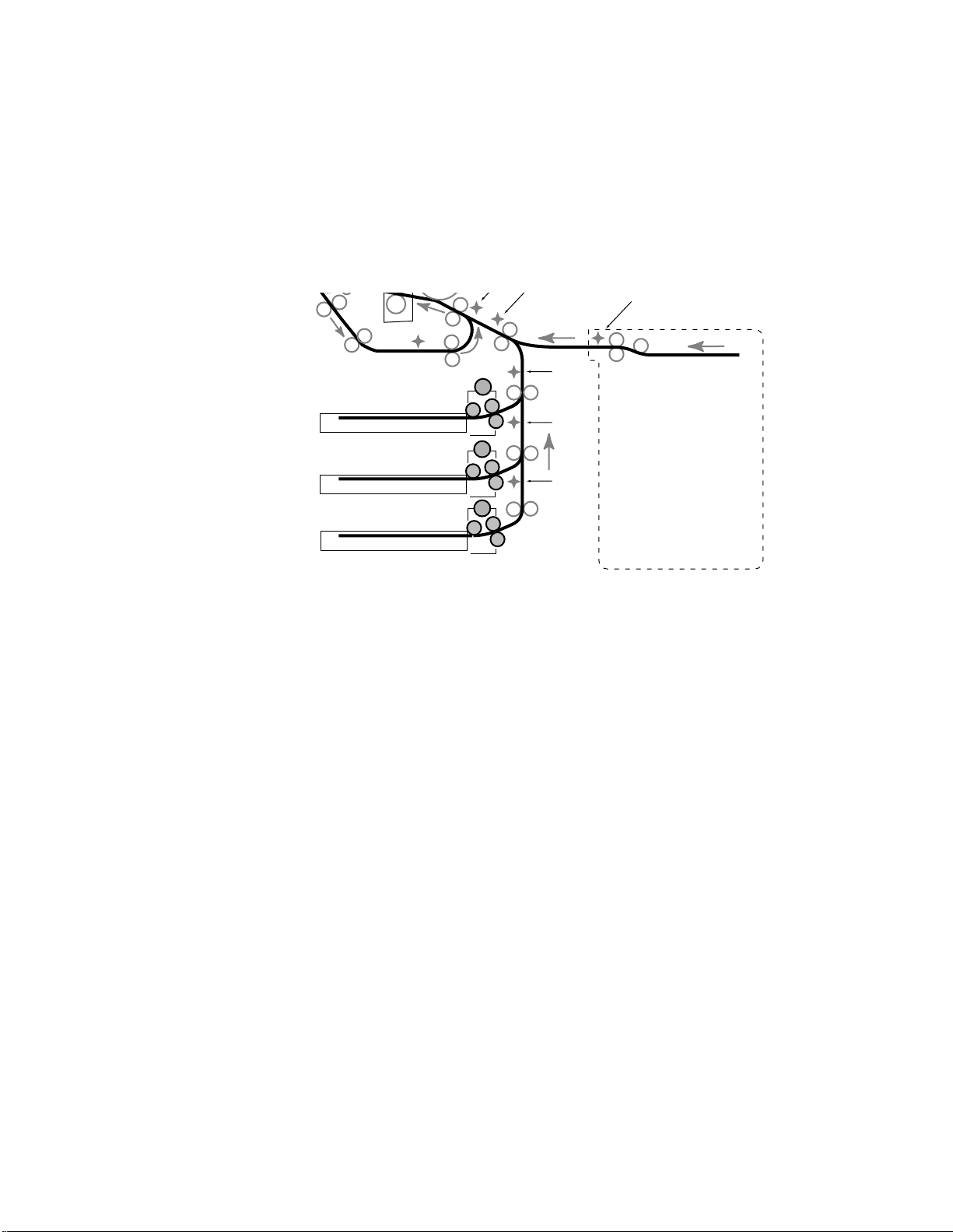
D640 Printer Service Manual
KSEN
2-7.2 Pick Motor System
The pick motor system contains three independent motor systems, one for each feed
unit (see Figure 2-35). The pick motor system controls picking the sheet from the tray
and feeding to the PS1passes the sheet to the transport motor system. The pick motor system operates at 180
mm/sec.
n (n
= 1, 2 or 3) sensor. At this point, the pick motor system
Duplex unit
Tray 1 pick motor
Pick rollers
Separation rollers
Upper tray
Tray 2 pick motor
Middle tray
Tray 3 pick motor
Lower tray
Figure 2-35 Pick Motor System
2-7.3 Transport Motor System
The transport motor system takes the sheet from the pick motor system and feeds the
sheet at a much higher speed of 630 mm/sec (see Figure 2-36). This higher speed can
sometimes be heard in the printer as a high pitch sound that occurs after a sheet is
picked. The transport motor system passes the sheet to the main motor system at the
registration rollers.
PS1-1
M
PS1-2
M
PS1-3
M
OPTIONAL
HIGH CAPACITY INPUT
(HCI)
2-46 Functional Overview June 08, 1999
Page 79
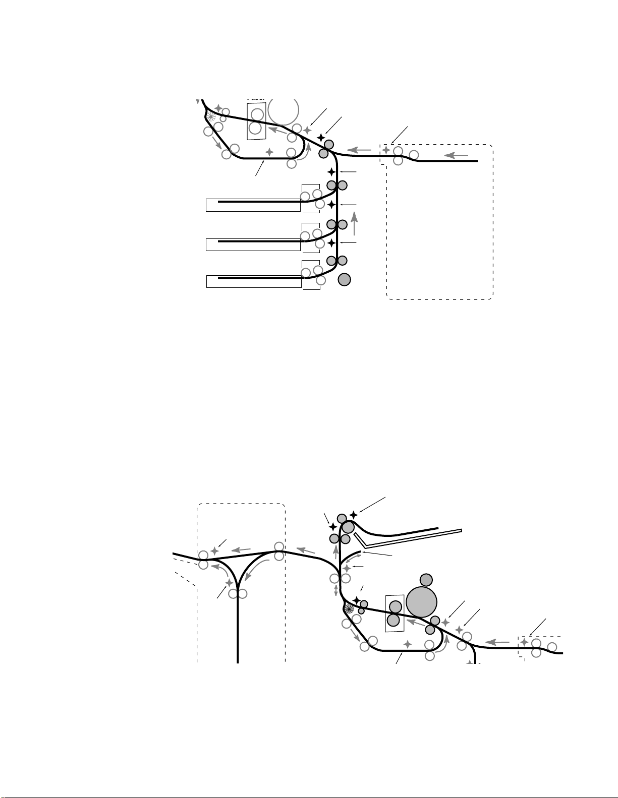
D640 Printer Service Manual
Fuser
D
ecurler
Drum
Duplex unit
PS5
Upper tray
Middle tray
Lower tray
Figure 2-36 Transport Motor System
2-7.4 Main Motor System
The main motor system takes the sheet from the registration rollers at a constant speed
of 180mm/sec (see Figure 2-37) and moves it through to the fuser. The fuser links the
main motor system to the drive E unit. The drive E unit takes the sheet from the fuser at
a constant speed of 180mm/sec and moves it through the whiffle roller to the ejection
tray. The reversing rollers have their own motor.
PS3
PS2
PS1-1
PS1-2
PS1-3
M
Transport feed
motor
KSEN
OPTIONAL
HIGH CAPACITY INPUT
(HCI)
The main motor system also drives both the developer coupling that drives the
developer and the waste toner unit that contains a long-spring auger that transports
waste toner up to the waste toner bottle.
Ejection tray full
PS7
HCO exit sensor
Long paper duplex path
Reversing
Switchback
sensor
unit
PS4
Decurler
Duplex unit
PS6
Fuser
Drive M (Main motor)
M
Drum
PS3
PS2
KSEN
Figure 2-37 Main Motor System
June 08, 1999 Functional Overview 2 -47
Page 80

D640 Printer Service Manual
K
2-7.5 Reversing Motor System
The reversing motor system has three different forward speeds and one reverse speed.
This the only motor in the D640 that can change directions (see Figure 2-38). The
reversing motor system function depends on whether the sheet is in simplex or duplex
mode:
In simplex mode, the reversing motor simply takes the sheet from the main motor
l
system and feeds the paper to the face down tray on top of the printer. The feeding
speed when the reversing unit is in simplex mode is a constant 180 mm/sec.
In duplex mode, the speed slows down to a rate of 133 mm/sec when the sheet
l
reaches the PS4 sensor just after the fuser unit. This slower rate is used to stop the
trailing edge of the paper at the top of the rubber paddle roller located on the exit
side of the decurler unit. The reversing motor takes the sheet from the main motor
system and feeds the sheet
sheet clears the upper roller of the duplex unit. At this point the reversing motor
reverses
is fed downward and passes to the duplex motor system.
Long size paper duplex path: Paper larger than letter or A4 is routed into a special
l
path located under the ejection tray at 630 mm/sec and reversed into the duplexer
at 630 mm/sec.
up
at 630 mm/sec. The high speed stops when the
the sheet’s direction and feeds the sheet
down
at 630 mm/sec. The paper
HCO exit sensor
Switchback
sensor
Figure 2-38 Reversing Motor System
2-7.6 Duplex Motor System
The duplex motor system has two speeds:
l The sheet is fed into the duplex unit at a slower speed of 180 mm/sec.
l The sheet is transported back to the registration rollers at a faster speed of 630 mm/
sec (see Figure 2-39).
The main motor system picks up the sheet from the duplex motor system at the
registration rollers.
Reversing
unit
Reversing
motor
PS7
M
PS4
Decurler
Duplex unit
Long paper duplex path
PS6
Fuser
Drum
PS3
PS2
2-48 Functional Overview June 08, 1999
Page 81
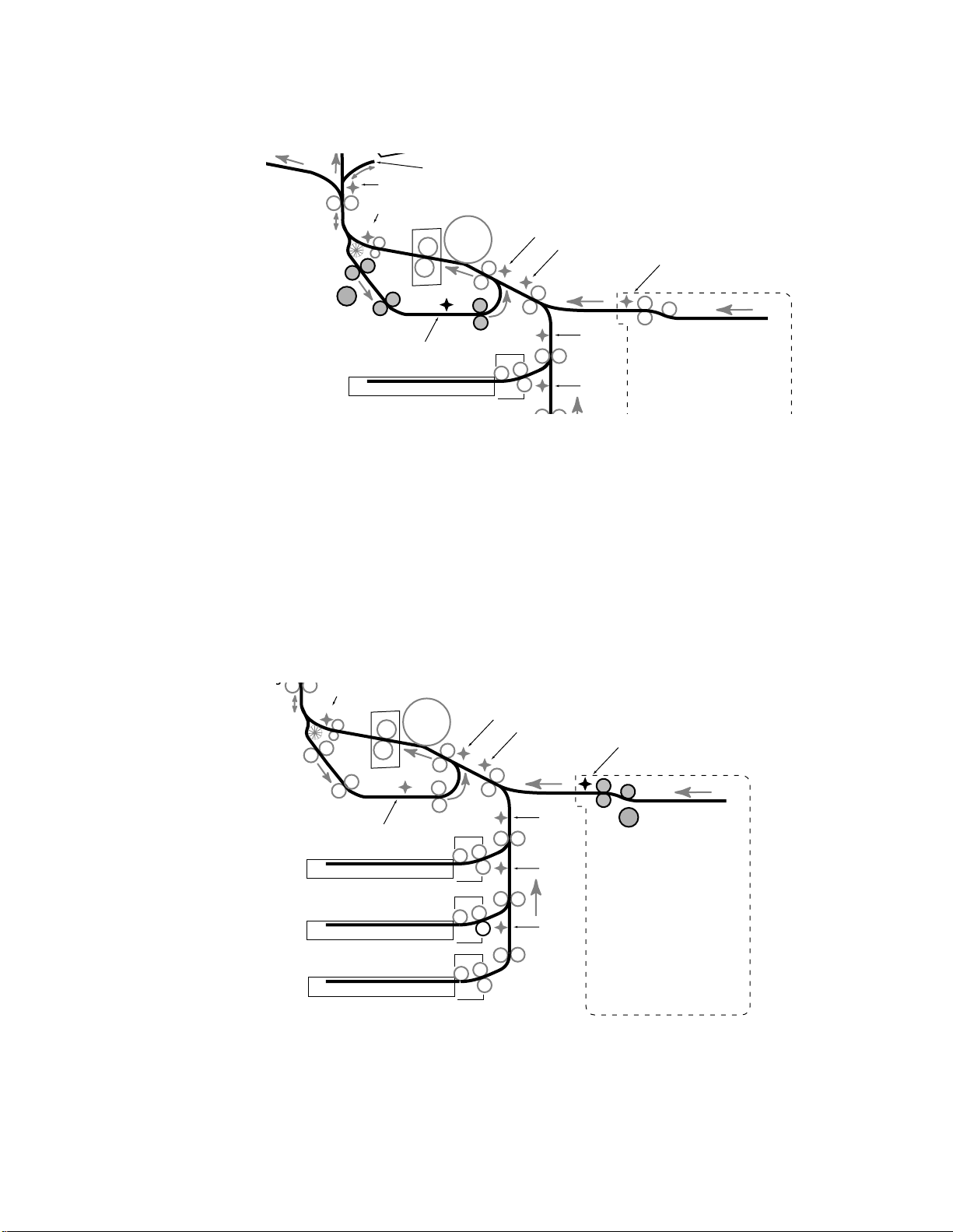
Reversing
ing
unit
PS6
PS4
Decurler
Long paper duplex path
Fuser
Drum
D640 Printer Service Manual
PS3
PS2
KSEN
Duplex motor
Duplex unit
PS5
Upper tray
Figure 2-39 Duplex Motor System
2-7.7 KMOT Motor System
The HCI has one paper feeding motor system, the KMOT motor system that picks and
transports the sheet at a constant rate of 350mm/sec. The sheet is fed by the KMOT
motor system to the printer’s transport motor system. Control of the sheet’s movement
changes from KMOT to the transport motor system immediately after the leading edge
of the sheet is through the paper feed rollers, but before the PS2 sensor in the printer.
This transfer of control from KMOT to the transport motor system is determined by a
fixed time period that starts when the leading edge of the paper triggers the KSEN
sensor.
PS4
M
Decurler
Fuser
Drum
PS1-1
PS1-2
PS3
PS2
KSEN
Duplex unit
PS5
Upper tray
Middle tray
Lower tray
PS1-1
PS1-2
PS1-3
M
KMOT motor
OPTIONAL
HIGH CAPACITY INPUT
(HCI)
Figure 2-40 KMOT Motor System
June 08, 1999 Functional Overview 2 -49
Page 82

D640 Printer Service Manual
2-7.8 HCO Feed Motor System
The HCO (both 2,000 and 3,000 sheet) feed motor system receives the sheet from the
D640’s main motor system at 180 mm/sec (see Figure 2-41). The HCO’s feed motor
feeds at a constant rate of 180 mm/sec. The HCO's feed motor has two possible
locations to pass the page depending if the HCO is in Face Up or Face Down mode:
In face up mode, the HCO feed motor feeds the page straight through the HCO. The
l
feed motor transfers the sheet to the HCO's exit and switchback motor system
immediately after the leading edge of the page activates the HCO exit sensor.
In face down mode, the HCO feed motor feeds the sheet down into the HCO's
l
switchback area where a switchback solenoid is activated to redirect the sheet. The
feed motor transfers the sheet to the HCO's exit and switchback motor system
immediately after the leading edge of the page activates the switchback sensor in
the switchback area.
Ejection tray full
PS7
Reversing
unit
PS6
PS4
Decurler
Long paper duplex path
Fuser
HCO exit sensor
Switchback
sensor
Feed
motor
M
Figure 2-41 HCO Feed Motor System
2-7.9 HCO Exit and Switchback Motor System
The HCO (both 2,000 and 3,000 sheet) exit and switchback motor system (see Figure
2-42) can receive the sheet from the HCO's feed motor system in two possible locations,
depending on whether the HCO is in face up or face down mode:
Face Up mode—The HCO exit and switchback motor system takes the sheet from
l
the HCO feed motor system immediately after the exit sensor is activated by the
leading edge of the sheet. The HCO exit and switchback motor system feeds the
sheet a short distance through the exit rollers and out to the exit tray at a constant
151 mm/sec. The slower speed of 151 mm/sec helps the stacking accuracy at the
HCO's output tray.
l Face Down mode—The HCO exit and switchback motor system takes the sheet
from the HCO feed motor system immediately after the switchback sensor is
activated by the leading edge of the page. The HCO exit and switchback motor
system transports the sheet
downward
trailing edge of the sheet leaves the switchback sensor. At this point the HCO exit
and switchback motor
reverses
direction and feeds the page
until the leading edge of the page activates the exit sensor. The HCO exit and
switchback motor slows down to the exit speed of 151 mm/sec and the sheet is
ejected out the exit rollers and into the exit tray.
at 885 mm/sec until a short time after the
Drum
PS3
upward
PS2
at 920 mm/sec
2-50 Functional Overview June 08, 1999
Page 83
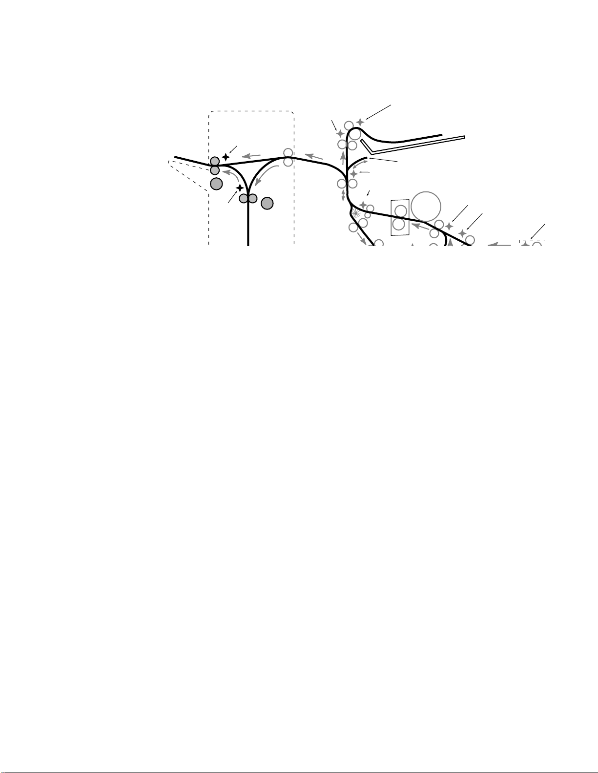
Ejection tray full
K
PS7
HCO exit sensor
Long paper duplex path
PS6
PS4
Decurler
Fuser
M
Exit motor
Switchback
sensor
Reversing
unit
M
Switchback
motor
Figure 2-42 HCO Exit and Switchback Motor Systems
D640 Printer Service Manual
Drum
PS3
PS2
June 08, 1999 Functional Overview 2 -51
Page 84

D640 Printer Service Manual
2-8 Paper Feed and Transport from Trays and HCI
Paper is fed from one of the three trays or from the High Capacity Input. Each sheet is
picked and transported to the registration rollers where it enters the print engine feed
path.
The three feed units and the transport roller in the printer are linked by a common belt
driven by the transport feed motor located on the printer frame directly to the rear of the
lower paper feed unit. Belt tension is maintained by the spring-loaded tensioner
mounted on the lower paper feed unit directly above the transport motor. The upper and
middle paper feed units are identical; the lower paper feed unit differs because it has the
feed belt tensioner mounted to it.
Note
Printers with serial numbers prior to JP20000330 had a second spring-loaded idler
assembly located on the printer frame directly below the transport roller.
The pick and separation roller assemblies on each paper feed unit are customer
replaceable consumables and should be replaced every 500,000 pages
(A4/Letter).
2-8.1 Paper Tray Lift Process - Paper Trays
At power up or reset, the mechanism controller checks the paper tray microswitches for
the presence of the three paper trays. When a tray is fully inserted, the paper tray
microswitch mounted on the printer rear frame closes and the tray lift motor is activated
for that particular tray.
The tray lift motor has a small brass gear connected to the motor shaft and a larger
white plastic gear with a series of holes around its perimeter. An actuator on the lift lever
shaft is inserted into one of the holes in the white plastic gear. When the tray lift motor
turns, the metal tab on the opposite end of the lift lever shaft turns pushing the paper
tray up so the front side raises. The lift motor stops when the top edge of the paper stack
hits the pick roller assembly which moves a metal flag through the pick roller up sensor.
2-52 Functional Overview June 08, 1999
Page 85

D640 Printer Service Manual
Lift motor gear
Actuator inserts
into gear
Lift lever shaft
Figure 2-43 Tray Lift Motor
Once the pick roller up sensor is activated, the paper empty sensor is checked. When
the tray is empty, the paper empty sensor actuator hangs through the hole in the base of
the paper tray and opens the sensor. A message “Tray x Paper Out” (x = 1, 2 or 3) is
displayed on the LCD panel.
June 08, 1999 Functional Overview 2 -53
Page 86
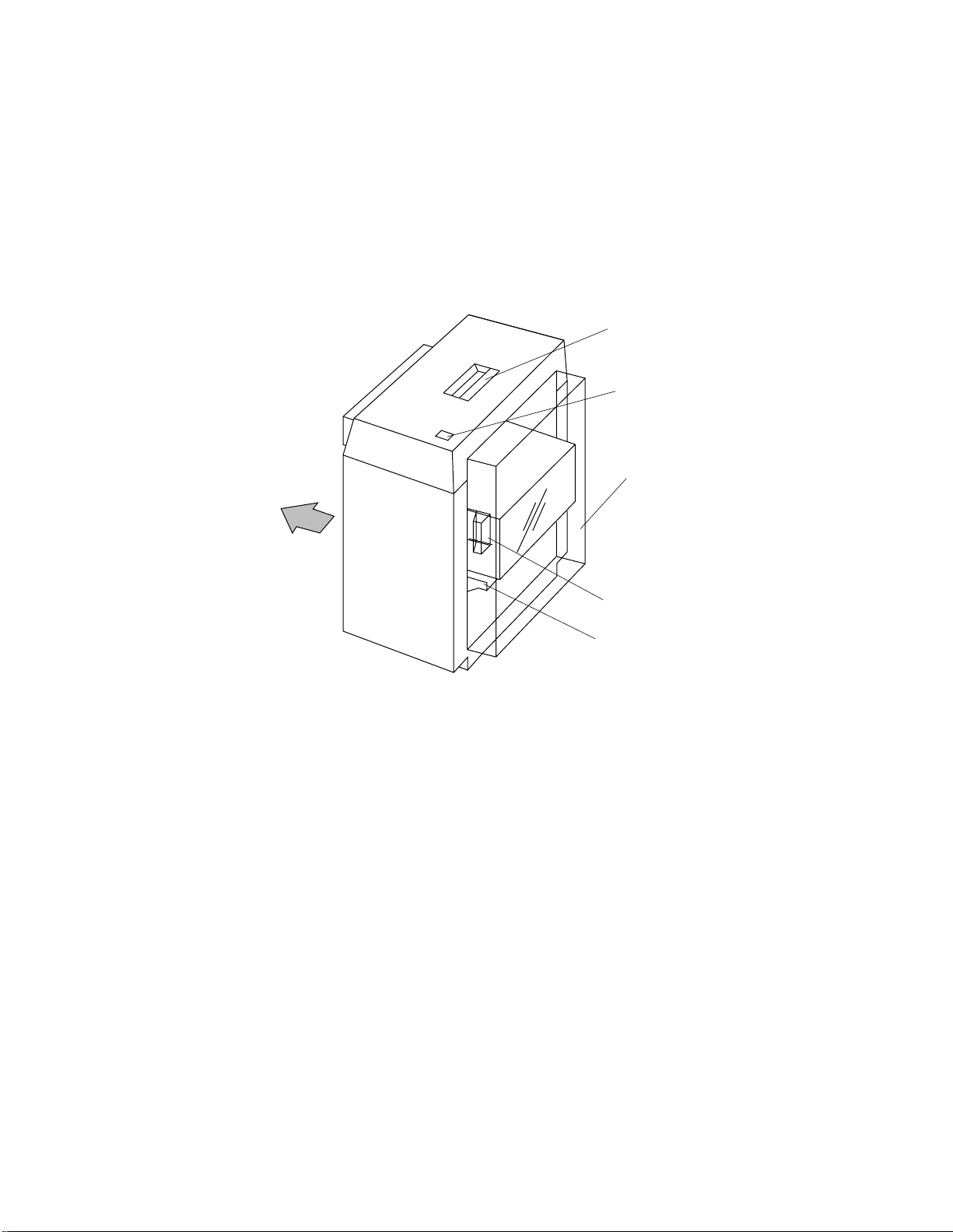
D640 Printer Service Manual
2-8.2 Paper Tray Lift Process - HCI
The optional 3000-sheet capacity High Capacity Input is powered directly from the
printer and is an alternative paper source. The HCI paper table can be moved down with
the switch on the top cover when the door is opened. The door open/closed position is
sensed by the DSEN sensor. When the door is closed, the paper table lifts until the pick
roller up sensor (LEVSEN) is activated and then the paper out sensor (EMPSEN) is
checked to verify paper is present on the paper table.
Printer
HCI release handle
Paper lowering button
HCI door
Figure 2-44 High Capacity Input
Door handle
Paper table
(inside door)
2-54 Functional Overview June 08, 1999
Page 87

2-8.3 Paper Pick Process - Paper Trays
Before the paper picking process can start, the mechanism controller must first detect
the following sequence:
Tray is present (tray present microswitch is closed)
1
Tray is correctly lifted (pick roller up sensor is closed)
2
Paper is in the tray (paper empty sensor is open)
3
Once the above three micro switches are detected as closed, that paper tray is ready to
accept a paper pick command.
D640 Printer Service Manual
LEVSEN
Pick rollers
EPSEN
(Paper tray empty sensor)
PS1- 1/2/3
Figure 2-45 Paper Feed Mechanism
When a paper pick command is received, the pick motor is turned on and the feed
rollers turn at a 180 mm/s rate to pull the top sheet from the tray. As the pick and feed
rollers are turning, the lower separation roller turns in the opposite direction pushing
back any other sheets below the picked sheet. This prevents a “multi-pick” condition.
June 08, 1999 Functional Overview 2 -55
Page 88

D640 Printer Service Manual
Figure 2-46 Paper Pick and Separation Rollers Rotation
Pick rollers rotate to
move top sheet forward
Separation roller moves in
opposite direction to separate
the second sheet from the first
Upper tray
Middle tray
Lower tray
An improper paper pick produces a “Tray
Pick error can occur for two reasons:
The time lapse is less than 310 ms between when the Pick Start command is sent to
l
the pick motor and when the leading edge of the picked sheet arrives at PS1 (-1, -2,
or -3). This error is caused by a “multi-pick” condition.
After three attempts (each 765ms long), the time lapse between when the Pick Start
l
command is sent to the pick motor and when the leading edge of the picked sheet
arrives at PS1 is greater than 765ms. This error is caused by a “no pick” condition.
n
In Error Log, the “Tray
Pick Error” conditions listed do not differentiate between above
reasons. This means it is the responsibility of the service technician to determine the
actual cause.
2-8.4 Paper Pick Process - HCI
The HCI utilizes a similar process to the paper trays. When a feed command is received,
the pick motor roller (KMOT) turns the paper pick, feed, and separation rollers. The pick
and feed rollers rotate on the upper paper surface to pick paper off the paper tray and
the separation roller rotates in the opposite direction on the lower paper surface to
assure only one sheet is picked. A diagnostic indicating the status of the sensors is
available from the maintenance menu (see D-3 "Diagnostics," on page D-6).
A jam sensor at the HCI paper exit (KSEN) verifies successful paper pick as the paper is
moved into the print engine where the printers feed roller drives the paper towards the
registration rollers. The paper-input guide that directs the paper from the HCI to the
printer has a Mylar strip on the printer door to improve paper handling.
n
Pick Error” (where n = 1, 2 or 3). A Tray
An improper HCI paper pick creates the an “HCI jam 1". This error occurs when the time
lapse is greater than 300 ms from when the paper is picked to when the leading edge of
the page activates the KSEN sensor (see D-4.2 "JAM51 HCI Pick Error," on
page D-12).
The HCI feed roller kit (includes the pick, feed, and separation rollers) is a consumable
and expected to be replaced by the customer every 500,000 pages.
2-56 Functional Overview June 08, 1999
Page 89

D640 Printer Service Manual
When the printer is using the HCI, it not uncommon for the printer to pick paper from a
tray containing the same size paper. This is normal operation when the printer needs
paper and the HCI is not ready (for example, when the elevator is bringing the paper into
position). The printer picks paper from one of the other trays in order to maintain its print
speed. If this is not desired, the trays should be locked
2-8.5 Transport Feed Path - Paper Tray and HCI
The transport feed path contains three sets of feed unit rollers (one for each tray) and
one set of transport rollers. The feed unit rollers are accessed from the lower-right cover.
The transport roller are accessed by removing the black plastic plate below the waste
developer bottle. The transport roller can be rotated by turning knob 1 (see Figure 2-4.)
All the rollers in the transport feed path are driven by the transport feed motor which is
mounted on the lower printer frame directly to the rear of the lowest feed unit.
After paper is successfully picked from a tray and the leading edge of the paper
n (n
activates PS1reach the PS2 sensor. If the time lapse between when the leading edge of the paper
activates PS1-
specified time (PS1-
= 1, 2 or 3), the paper is then allotted a specified period of time to
n
and PS2 is longer the specified time, a “Feed Path Jam n” results. The
n
to PS2) for each tray is as follows:
Tray 1—If time from PS1-1 to PS2 is longer than 220ms then “Feed Jam 1" occurs
l
Tray 2—If time from PS1-2 to PS2 is longer than 420ms then “Feed Jam 2" occurs
l
Tray 3—If time from PS1-3 to PS2 is longer than 620ms then “Feed Jam 3" occurs
l
A “Paper at Tray n” status message occurs if paper is left at the PS1-1, PS1-2 or PS1-3
sensor after a printer reset.
When a page is picked by the HCI, it is possible to get an HCI feed jam 1 or 2. The
meaning of an HCI feed jam is as follows:
“HCI Jam 2" message indicates an “HCI feed jam 1". This HCI feed jam 1 occurs
l
when the time lapse between when the leading edge of the page arrives at the
KSEN and the trailing edge leaves KSEN is greater than 655ms. This type of HCI
feed jam indicates that a “multi-pick” condition may exist or HCI feed rollers are dirty.
“Paper at HCI” status message occurs when paper is present at the KSEN sensor
l
after a printer reset. This type of feed jam could be the result of many causes. A
printer reset can occur due a customer opening the printer front door, a power
failure, a customer doesn’t remove all paper after previous jam, etc.
June 08, 1999 Functional Overview 2 -57
Page 90
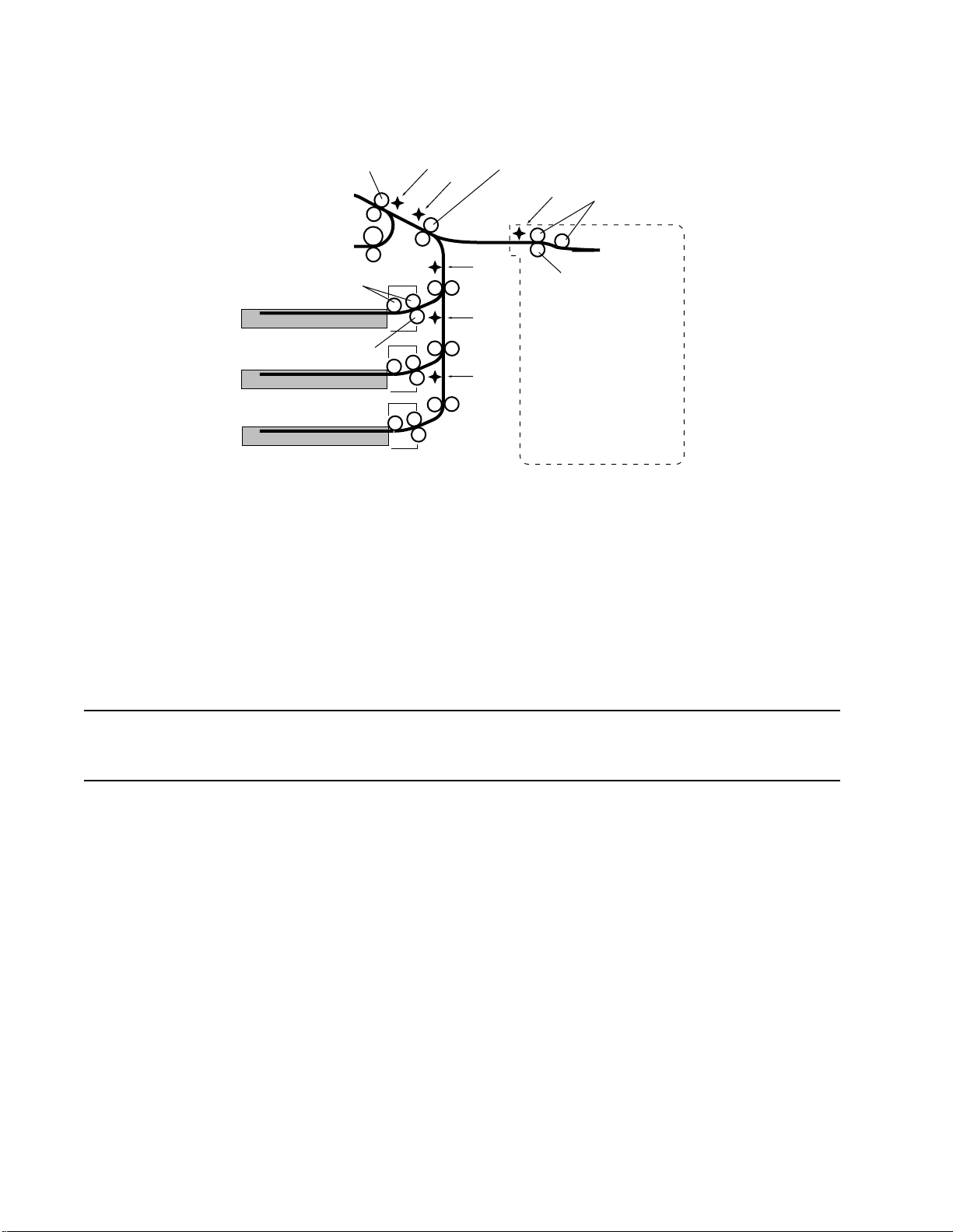
D640 Printer Service Manual
Registration rollers
Pick rollers
Upper tray
Separation roller
Middle tray
Lower tray
PS3
PS2
Transfer feed rollers
PS1-1
PS1-2
PS1-3
KSEN
Pick rollers
Separation roller
OPTIONAL
HIGH CAPACITY INPUT
(HCI)
Figure 2-47 Paper Transport Feed Path
When the leading edge of the paper reaches the PS2 sensor, it is still possible to get a
“Feed path jam 4" under the following conditions:
When the time lapse between when the leading edge of the page activates PS2 and
l
PS3 is longer than 150ms. This condition occurs when the page gets stuck under
PS2 or when PS2 is not working correctly.
When a page is detected under PS2 after a printer reset, a “Paper at HCI” status
l
message is displayed. A printer reset can occur when a customer opens the front
door, a power failure, a customer doesn’t remove all paper after previous jam, etc.
Note
In Error Log, the “Feed Path Jam 4" conditions listed do not differentiate between the
above reasons. It is the responsibility of the service technician to determine the actual
cause.
2-9 Print Engine Feed Path and the Print Process
2-9.1 Engine Feed Path
The print engine feed path consists of the registration rollers, the fuser assembly, and
the decurler assembly rollers, all driven by the main motor.
When the drum is in position to assure proper image placement on the paper, the
registration clutch is turned on to enable drive M to rotate the registration rollers. The
registration rollers drive the media between the drum and the transfer assembly guide,
where the image is transferred from the drum to the media by the transfer charger. The
separation charger is then activated to neutralize the transfer charge on the paper,
assuring the media will separate from the drum and enter the fuser.
2-58 Functional Overview June 08, 1999
Page 91

D640 Printer Service Manual
The media is driven into the fuser rollers by the registration rollers, which fuses the toner
image onto the paper with heat and pressure. The fuser drives the media through the
decurler assembly, which is composed of offset rollers to remove some of the paper curl
induced when the media was heated in the fuser. Directly after the decurler rollers is
sensor PS4. If paper does not reach PS4 in the allotted time, a “Fusing Unit Jam 1" is
posted to the control panel display.
The main motor drives the registration rollers, developer, drum, and fuser (which drives
the drive E unit). The developer is driven by the developer coupling. When handle b1is
rotated clockwise from its’ vertical position, the developer coupling is pulled from the
developer drive gears to allow the developer unit to move to the right, away from the
drum.The main motor also drives the waste toner auger that drives a long-spring auger
that transports waste toner up to the waste toner bottle or back to the toner hopper. The
waste toner auger is a separate part and not part of drive M unit.
Main Motor
Figure 2-48 Main Motor
2-9.2 Paper De-Skewing Process
When the leading edge of the paper reaches PS3, a timer starts that determines when
to shut off the transport feed motor. The timer determines how much feeding is done to
create a small bow where the leading edge of the paper is driven into the stationary
registration rollers. This bow is critical for automatic de-skewing.
The de-skewing process is as follows:
The leading edge of the paper fed by the transport feed rollers activates the PS3
1
sensor and starts the de-skewing timer
2 Paper is fed up to the registration rollers, which are stationary (not turning).
3 The transport feed rollers continue feeding paper creating a small bow in the paper
at the registration rollers. The transport feed rollers continue to feed paper (about
5mm) until the de-skewing timer stops the transport feed rollers.
This process of extra feeding has the effect of de-skewing the paper.
June 08, 1999 Functional Overview 2 -59
Page 92
D640 Printer Service Manual
Stationary Registration Rollers
Approximately
5mm bow
2
1
Sheet feeding into registration
rollers slightly skewed
Resgistration
rollers
Transfer feed
rollers
Figure 2-49 Paper De-Skewing
Sheet stopped at registration
rollers creating a bow in the
sheet and straightening out
the skew
PS3
Sheet with bow
PS2
Side View
2-60 Functional Overview June 08, 1999
Page 93

2-9.3 Paper Input Shift
There are six paper input systems: Tray 1, Tray 2, Tray 3, HCI, Duplex-H, and Duplex-V .
Paper from each input system has a slightly different horizontal position when it reaches
the registration rollers due to skew and paper shift. The printer accommodates each
different horizontal position by shifting the print image on the drum to align with the
position of the paper. This alignment is made when a Paper Feed System Alignment is
done (see 5-3.4 "Paper Feed System Alignment," on page 5-12 for procedure). The
shift is made by delaying or advancing the start and stop of the laser beam.
Tray 1
Tray 2
D640 Printer Service Manual
The image on the drum is
shifted to center the image
on the paper from each
paper input system.
Tray 1
Tray 2
Registration Rollers
Sheets from two different paper input
systems feeding into registration
rollers. Each sheet arrives at the
rollers in a different position.
Figure 2-50 Paper Input Image Alignment
June 08, 1999 Functional Overview 2 -61
Page 94

D640 Printer Service Manual
2-9.4 Image Transfer and Drum/Paper Separation
As the paper is fed from the registration roller, it passes between the drum and transfer
assembly where the image developed on the drum is transferred to the paper. See 2-6
"Electrophotographic Printing Process," on page 2-39 for a description of the drum and
electophotographic process.
The transfer assembly guide contains the transfer LEDs and the transfer unit. The
transfer unit holds the transfer and separation charge wires.The transfer assembly guide
consists of:
Transfer charge wire—A high voltage DC electrode which transfers the image from
l
the photoconductive drum onto the media. The transfer charge voltage is called
+HV.
Separation charge wire—A high voltage AC electrode (10 KVac 500HZ with a DC
l
offset) that discharges the media to allow it to separate from the drum surface. The
AC separation voltage is called ACH.
Transfer LEDs—Located directly below the transfer charge wires and shine through
l
the transfer charge wires.
The image on the drum is rotated to meet the paper at the transfer assembly guide. The
transfer charge wire places a high positive charge behind the paper to attract the image
toner from the drum onto the paper. At the same time, the transfer LEDs shine up
around the transfer charge wire discharging the drum to assist in toner separation,
especially for lighter paper weights (less than 18 lb).
The electrostatic charge on the paper creates an attraction to the drum surface.
Immediately after the image is transferred to the paper, the paper passes over the
separation wire to completely discharge the paper and remove any attraction of the
paper to the drum.
The voltages on the transfer and separation charge wires change as the paper crosses
the transfer assembly. They start at a high value and decrease in three stages until the
end of the paper has left the area. The values differ for paper coming from the duplexer.
The new high voltage power supply changes the way the separation process functions.
Instead of supplying a constant voltage to the separation charge wire, the new power
supply maintains a constant current.
The transfer unit should be cleaned whenever working on the printer (see 4-6
"Performing Weekly User Maintenance," on page 4-13). The transfer unit is a
consumable that comes with the drum kit and replaced with the drum (see 1-7
"Consumables," on page 1-12).
After passing the separation charge wire, the paper moves between the rear of the
transfer guide assembly and star roller guide to the fuser area. The star roller guide is
part of the clear plastic cover of the erase LEDs. The star roller guide assists paper with
a natural curl from raising above the paper path and wrapping around the drum. The star
roller guide is important in handling Fusing Jam 1 problems.
2-62 Functional Overview June 08, 1999
Page 95

2-9.5 Fuser Unit
After the paper has the image transferred to it, it moves to the fuser unit. The fuser unit
applies heat and pressure to fuse the toner to the paper. There are two different fusers:
120-127 Vac and 200-240 Vac.
D640 Printer Service Manual
Fuser unit
Reversing unit
Rubber paddle
roller
Cleaning roller
(Sponge impregnated
with silicon oil covered
with nylon felt)
Paper path
Decurler unit
Upper
roller
Upper
roller
Paper path
Lower
roller
Duplex unit
Halogen light
Teflon-coated
aluminum
Lower
roller
(Silicon rubber with
graphite impregnated
surface)
Figure 2-51 Fuser Unit
In the fuser unit, the paper is rolled between an upper hot roller and a lower rubber
pressure roller. The upper roller is heated by an AC-powered halogen lamp. The
mechanism controller maintains the roller temperature at 180°C by reading the thermal
sensor riding on the outside of the roller every 500ms and turning on and off the lamp.
To resolve certain fusing or curl problems, the roller temperature can be adjusted
between 205°C and 165°C using the control register 1D (see 3-13.29 "Control Info
Menu (EngMaint.Control)," on page 3-56).
The springs at each end of the lower rubber pressure roller press the roller and the
paper against the upper hot roller. With the correct heat and pressure, the toner is fused
into the paper surface.
June 08, 1999 Functional Overview 2 -63
Page 96

D640 Printer Service Manual
A silicon impregnated cleaning roller rides on the hot roller to clean off any excess toner
that may accumulate on the hot roller.
If the mechanism controller detects a low or high temperature condition:
SVC 27—The fuser did not reach 185°C within 200 seconds after power on or cover
l
closing (see 4-9.6 "SVC 27 Fuser Time-out Alarm," on page 4-26)
SVC 28—the temperature was detected above 225°C twice consecutively
l
(see 4-9.7 "SVC 28 Fuser High-Temperature Alarm," on page 4-28)
SVC 29—The temperature was detected below 155°C twice consecutively
l
(see 4-9.8 "SVC 29 Fuser Low-Temperature Alarm," on page 4-30)
If the fuser temperature goes above 260°C, the hardware breaker on the fuser assembly
trips. This breaker is resetable.
The fuser is a consumable and is scheduled to be replaced every 300,000 letter/A4
images. The silicon impregnated cleaning roller in the fuser is also a consumable and
replaced every other time toner is added. The cleaning roller is part of the toner kit (see
1-7 "Consumables," on page 1-12). The current fuser usage percentage is printed on
the Maintenance Report.
The drive gear on the fusing assembly serves as the drive linkage between drive M unit
and drive E unit. Removing the fuser disconnects the linkage.
2-9.6 Decurler Unit
The heat and pressure of the fuser's rollers creates an upward curl in the paper. Once
the paper has left the fuser, the paper enters the decurler. The decurler routes the paper
through a bend to flatten the paper for more reliable feeding, reduced paper jams, and
improved paper stacking.
Reversing unit
Rubber paddle
Figure 2-52 Decurler Unit
roller
Duplex unit
PS4
Fuser unit
Decurler unit
Decurer
rollers
Paper path
The paper then moves to the rubber paddle roller at the junction of the decurler, duplex
unit, and reversing unit. The rubber paddle roller has teeth that are important for
directing the paper. The roller directs the paper from the decurler to the reversing unit.
2-64 Functional Overview June 08, 1999
Page 97

When a duplex operation has been selected, the paddle roller redirects the paper down
into the duplex path. The reversing unit stops the paper with the trailing edge of the
paper still in the teeth of the constantly turning roller. As the paper reverses, the teeth
redirect the paper into the duplex unit.
The decurler unit has a decurler knob and a decurler lever. The decurler knob rotates
the paddle roller (counter-clockwise) which advances the paper away from the fuser unit
and PS4. The decurler lever is spring loaded upwards and holds the paper in the
decurler unit. By pulling down on the decurler lever, the decurler rollers separate to
relieve the pressure on any paper in the decurler unit.
The decurler unit contains the jam sensor PS4 which detects paper coming from the
fuser. PS4 is located at the rear of the assembly to keep it away from the heat generated
by the fuser. The jam timing is precise enough that the printer takes into consideration
that the paper is slightly shorter after having gone through the fuser.
2-9.7 Reversing Unit
The rubber paddle roller directs the paper from the decurler into the reversing unit.
D640 Printer Service Manual
Ejection unit
Top bin
Long paper
deflector
PS6
HCO
Long paper duplex path
HCO paper
deflector
Reversing unit
from decurling unit
Figure 2-53 Reversing Unit
From the reversing unit, the paper can go into one of four possible routes:
l Top Output Bin—If neither of the solenoids is selected to deflect the paper and the
paper is not to be sent to the duplexer, the paper goes to the ejection unit where it is
ejected into the top output bin.
l High Capacity Output—The first junction is the HCO deflector that can deflect the
paper into the HCO. The HCO deflector is switched into position by the HCO select
solenoid mounted on the rear of the reversing unit. The HCO select solenoid has a
June 08, 1999 Functional Overview 2 -65
Page 98

D640 Printer Service Manual
magnet to keep it locked in one position and a spring to keep it locked in the other.
When the paper is to be directed to the HCO the solenoid is energized to draw the
plunger in. When the current is removed, the solenoid is held in place by a magnet.
When the paper is to be directed toward the upper tray, the polarity of the signal is
reverse on the mechanism and the solenoid is pushed out. The current is then
removed and the plunger is held in this position by a spring.
Duplex—If the paper is not long enough to need to go into the long paper path, the
l
paper is routed toward the ejection unit until the time value (PS6) for the paper size
has been reached. The PS6 sensor in the reversing unit is not used as a paper jam
sensor but as a timing sensor for the mechanism controller to determine when the
paper can be reversed. The mechanism controller knows the length of the paper
and the activation of PS6 starts a timing sequence that the mechanism controller
uses to determine when the trailing edge of the paper has reached paddle roller in
the decurler unit. This is precisely timed and at the end of the timing sequence, the
paper is reversed and the paddle roller directs the paper into the duplexer. The
length of this timing sequence will vary for different lengths of paper.
Duplex Long Paper Path—The second junction in the reversing unit is the Long
l
Paper deflectors. Long paper that is being duplexed is deflected into a cavity
beneath the top cover to prevent the top portion of the paper from appearing
momentarily out of the upper ejection unit. The upper solenoid is only energized
when the paper is to be directed into the cavity below the top cover. The solenoid
remains energized until the reversed paper has cleared the area and is routed to the
duplexer. When the time value (PS6) for the paper size has been reached, the
reversing motor on the reversing unit reverses direction and drives the paper
downward into the duplexer.
The reversing rollers are driven by the reversing motor mounted on the rear of the
reversing unit. The reversing can run at four different speeds depending on the paper
route (see 2-7.5 "Reversing Motor System," on page 2-48).
2-9.8 Duplex Unit
Once the trailing edge of the paper has cleared the decurler unit, the paper is reversed
and the paddle roller directs the paper into the duplex unit. The duplex unit directs the
paper back to the registration rollers but with the paper reversed so the non-printed side
is exposed to the drum. During multiple page duplex jobs, as the paper is traveling
through the duplexer, the drum and fuser units are printing another page.
2-66 Functional Overview June 08, 1999
Page 99

from reversing unit
D640 Printer Service Manual
to registration
rollers
PS5
Paper jam
access handle
Figure 2-54 Duplex Unit
The duplex motor, located on the rear of the duplex unit, drives three sets of rollers in
the duplexer with a cogged belt (see 2-7.6 "Duplex Motor System," on page 2-48).
When the media enters the duplexer, it is driven past jam sensor PS5 to the duplex
registration rollers. The duplex motor is then switched off momentarily to allow the
synchronization of feeding alternate sheets from the paper trays and duplexer by the
mechanism controller. The duplex motor is then turned on again to feed the media to the
printer registration rollers.
The operation of the registration and fusing areas of the printer are the same as simplex
printing, but the timing for PS4 and PS7 changes slightly. When the second side is
printed:
For single page duplex jobs, the back side of the page sequence allows for correct facedown stacking.
Figure 2-55 Single Page Duplex Printing
For multiple page duplex jobs, the mechanism controller interleaves images, printing
image 2 and image 4 from the selected input source, then printing image 1 and image 3
from the duplexer, image 6 from the input source, and then image 5 from the duplexer.
This image interleaving continues until the duplex job is completed.
June 08, 1999 Functional Overview 2 -67
Page 100

D640 Printer Service Manual
Figure 2-56 Multiple Page Duplex Printing
PS5 jam sensor is responsible for duplexer timing and for the two Duplex Printing Path
jams (see 4-10.14 "JAM31 Duplex Printing Path Jam 1," on page 4-100).
2-10 Ejection Path for Ejection Unit and HCO
The reversing unit is the junction point that determines the direction the paper will go
after the decurler unit. If the paper is not sent to the duplex unit, the paper can be either
be sent to the High Capacity Output (HCO) or the ejection unit and the top paper bin.
There are two versions of the HCO, the 2,000-sheet HCO and the 3,000-sheet HCO.
2-10.1 Ejection Unit and Top Bin
The ejection unit is driven by the drive E unit, a gear and belt assembly that connects to
the main motor through the fuser drive gear. The paper is passed to the ejection unit
rollers by the reversing unit rollers where it activates sensor PS7 and is presented to the
top output tray by a second set of drive rollers. PS7 is a jam sensor that also indicates to
the printer that the printed page has successfully reached the output bin and does not
need to be reprinted in case of jam.
When the top output tray is full, the stacker full sensor flag moves away from its’ sensor
and an “Output Stacker Full” message is posted to the operator panel and printing is
halted until the output stack is removed.
PS7 sensor is responsible for the two Ejection Unit Jams (see 4-10.12 "JAM29 Ejection
Unit Jam 1," on page 4-96 and 4-10.13 "JAM2B Ejection Unit Jam 2," on page 4-98).
2-68 Functional Overview June 08, 1999
 Loading...