

Page 1

HP D640 Cut Sheet Printer
Technical Reference Manual
Hewlett-Packard Company
C5630-90030
E1098
Page 2

Notice
Hewlett-Packard makes no warranty of any kind with regard to this material, including,
but not limited to, the implied warranties of merchantability and fitness for a particular
purpose. Hewlett-Packard shall not be liable for errors contained herein or for
incidental or consequential damages in connection with the furnishing, performance, or
use of this material.
Hewlett-Packard assumes no responsibility for the use or reliability of its software on
equipment that is not furnished by Hewlett-Packard.
This document contains proprietary information which is protected by copyright. All
rights are reserved. No part of this document may be photocopied, reproduced, or
translated to another language without the prior written consent of Hewlett-Packard
Company. The information contained in this document is subject to change without
notice.
Printing History
The dates on the title page change only when a new edition is published.
Edition 2.0. . . . . . . . . . . . . . .October 1998
Copyright ©1998 Hewlett-Packard Company
All rights reserved.
October 1998
Please address any comments or questions to:
Publications Manager
System Peripherals Operation
HP D640 Printers - MS 44MC
Hewlett-Packard Company
19111 Pruneridge Avenue
Cupertino, CA 95014
ii
Copyrights and Trademark Credits
Adobe™, PostScript™, PostScript II, the PostScript Logo™, and ITC Zapf Dingbats are
trademarks of Adobe Systems Incorporated which may be registered in certain
jurisdictions.
Portions of the software in the PostScript Emulation Kit are Copyright © 1990-1998
Pipeline Associates, Inc. Certain portions protected by U.S. Patent No. 5,150,454.
PCL is a trademark of the Hewlett-Packard Company.
CG Times, a product of Agfa Corporation, is based on T imes New Roman, a registered
trademark of Monotype Corporation PLC.
Times Roman is a trademark of Linotype AG and its subsidiaries.
Univers is a registered trademark of Linotype AG and its subsidiaries.
Other product names mentioned in this manual may also be trademarks and are used
here for identification only.
Page 3

Contents
1. Introduction
Other D640 Manuals . . . . . . . . . . . . . . . . . . . . . . . . . . . . . . . . . . . . . 1
2. Printing Options
Custom Paper Sizes . . . . . . . . . . . . . . . . . . . . . . . . . . . . . . . . . . . . . 3
At the Control Panel . . . . . . . . . . . . . . . . . . . . . . . . . . . . . . . . . . 3
In Your Print Job . . . . . . . . . . . . . . . . . . . . . . . . . . . . . . . . . . . . . 4
Media Eject Length . . . . . . . . . . . . . . . . . . . . . . . . . . . . . . . . . . . 4
Page Width . . . . . . . . . . . . . . . . . . . . . . . . . . . . . . . . . . . . . . . . . 4
Select Custom Paper . . . . . . . . . . . . . . . . . . . . . . . . . . . . . . . . . 5
Paper Output Trays . . . . . . . . . . . . . . . . . . . . . . . . . . . . . . . . . . . . . . 5
PCL and PJL Output Commands . . . . . . . . . . . . . . . . . . . . . . . . 5
Example Paper Handling Configurations . . . . . . . . . . . . . . . . . . 6
Edge to Edge Printing . . . . . . . . . . . . . . . . . . . . . . . . . . . . . . . . . . . . 8
Working with Multiple Copies. . . . . . . . . . . . . . . . . . . . . . . . . . . . . . 12
CCITT Groups 3 and 4 Decompression. . . . . . . . . . . . . . . . . . . . . . 13
Image Position. . . . . . . . . . . . . . . . . . . . . . . . . . . . . . . . . . . . . . 14
LaserJet Compatibility . . . . . . . . . . . . . . . . . . . . . . . . . . . . . . . . . . . 15
Paper Input . . . . . . . . . . . . . . . . . . . . . . . . . . . . . . . . . . . . . . . . 15
Example Configuration . . . . . . . . . . . . . . . . . . . . . . . . . . . . . . . 16
Paper Output. . . . . . . . . . . . . . . . . . . . . . . . . . . . . . . . . . . . . . . 17
Internal Fonts . . . . . . . . . . . . . . . . . . . . . . . . . . . . . . . . . . . . . . 18
3. Working with TIFF Images
About TIFF Images . . . . . . . . . . . . . . . . . . . . . . . . . . . . . . . . . . . . . 19
Printing TIFF Images . . . . . . . . . . . . . . . . . . . . . . . . . . . . . . . . . . . . 19
Using the Control Panel . . . . . . . . . . . . . . . . . . . . . . . . . . . . . . 20
Using Commands in a Print Job . . . . . . . . . . . . . . . . . . . . . . . . 20
General Rules . . . . . . . . . . . . . . . . . . . . . . . . . . . . . . . . . . . . . . . . .21
Errors. . . . . . . . . . . . . . . . . . . . . . . . . . . . . . . . . . . . . . . . . . . . . . . . 24
TIFF Structure and Fields . . . . . . . . . . . . . . . . . . . . . . . . . . . . . . . . 25
Baseline TIFF . . . . . . . . . . . . . . . . . . . . . . . . . . . . . . . . . . . . . . 25
Extended TIFF. . . . . . . . . . . . . . . . . . . . . . . . . . . . . . . . . . . . . . 32
Unsupported Functions . . . . . . . . . . . . . . . . . . . . . . . . . . . . . . . . . . 33
TIFF Images as Part of PCL . . . . . . . . . . . . . . . . . . . . . . . . . . . . . . 34
Introducing PCL Compression Method 10 . . . . . . . . . . . . . . . . 34
Transparency mode with TIFF . . . . . . . . . . . . . . . . . . . . . . . . . 36
Example of PCL compression method 10. . . . . . . . . . . . . . . . . 39
iii
Page 4

4. Using the Printer’s Hard Disk
Data Directories. . . . . . . . . . . . . . . . . . . . . . . . . . . . . . . . . . . . . . . . 41
Printer Data Directories. . . . . . . . . . . . . . . . . . . . . . . . . . . . . . .41
User Data Directories . . . . . . . . . . . . . . . . . . . . . . . . . . . . . . . . 41
File System Conventions . . . . . . . . . . . . . . . . . . . . . . . . . . . . . . . . . 42
Long Filenames. . . . . . . . . . . . . . . . . . . . . . . . . . . . . . . . . . . . . 42
Lowercase in Filenames . . . . . . . . . . . . . . . . . . . . . . . . . . . . . . 43
Default Drive . . . . . . . . . . . . . . . . . . . . . . . . . . . . . . . . . . . . . . .43
Commands to Read/Write to Hard Disk. . . . . . . . . . . . . . . . . . . . . . 43
Initialize . . . . . . . . . . . . . . . . . . . . . . . . . . . . . . . . . . . . . . . . . . .44
Make Directory on Disk . . . . . . . . . . . . . . . . . . . . . . . . . . . . . . . 44
Store a PCL Print File on the Internal Hard Disk. . . . . . . . . . . . 45
Delete a File From Disk. . . . . . . . . . . . . . . . . . . . . . . . . . . . . . . 46
Using a Disk File in a PCL Job . . . . . . . . . . . . . . . . . . . . . . . . . 47
Utilities . . . . . . . . . . . . . . . . . . . . . . . . . . . . . . . . . . . . . . . . . . . . . . . 51
5. Control Codes
PCL Comparison . . . . . . . . . . . . . . . . . . . . . . . . . . . . . . . . . . . . . . . 53
HP-GL/2 Graphics (Vector Graphics) . . . . . . . . . . . . . . . . . . . . . . . 62
PJL Commands . . . . . . . . . . . . . . . . . . . . . . . . . . . . . . . . . . . . . . . . 66
PJL Environment Variables and Commands . . . . . . . . . . . . . . . . . . 70
PJL Error Codes . . . . . . . . . . . . . . . . . . . . . . . . . . . . . . . . . . . . . . . 79
6. Printer Fonts
Built-In Fonts . . . . . . . . . . . . . . . . . . . . . . . . . . . . . . . . . . . . . . . . . . 87
Virtual Font Cartridges. . . . . . . . . . . . . . . . . . . . . . . . . . . . . . . . . . . 88
Activating a Font Cartridge Using PJL . . . . . . . . . . . . . . . . . . . 88
Creating Your Own Font Cartridge . . . . . . . . . . . . . . . . . . . . . . 88
List of Font Cartridges . . . . . . . . . . . . . . . . . . . . . . . . . . . . . . . . . . . 89
Arabic . . . . . . . . . . . . . . . . . . . . . . . . . . . . . . . . . . . . . . . . . . . .89
Cyrillic . . . . . . . . . . . . . . . . . . . . . . . . . . . . . . . . . . . . . . . . . . . . 89
Greek. . . . . . . . . . . . . . . . . . . . . . . . . . . . . . . . . . . . . . . . . . . . . 90
Hebrew . . . . . . . . . . . . . . . . . . . . . . . . . . . . . . . . . . . . . . . . . . . 90
Latin 2 . . . . . . . . . . . . . . . . . . . . . . . . . . . . . . . . . . . . . . . . . . . .91
Latin 5 . . . . . . . . . . . . . . . . . . . . . . . . . . . . . . . . . . . . . . . . . . . .91
Barcodes 3 of 9 OCR-A. . . . . . . . . . . . . . . . . . . . . . . . . . . . . . . 91
Barcodes & More. . . . . . . . . . . . . . . . . . . . . . . . . . . . . . . . . . . .92
Brilliant Presentations I, Compelling
Publications II . . . . . . . . . . . . . . . . . . . . . . . . . . . . . . . . . . . . . . 92
CG Times Scalable . . . . . . . . . . . . . . . . . . . . . . . . . . . . . . . . . . 93
CG Triumvirate Condensed. . . . . . . . . . . . . . . . . . . . . . . . . . . . 93
Courier 1 . . . . . . . . . . . . . . . . . . . . . . . . . . . . . . . . . . . . . . . . . .93
Courier Document 1 . . . . . . . . . . . . . . . . . . . . . . . . . . . . . . . . . 94
Courier Portrait & Landscape . . . . . . . . . . . . . . . . . . . . . . . . . . 94
Decorative Words I . . . . . . . . . . . . . . . . . . . . . . . . . . . . . . . . . . 94
iv
Page 5

Distinctive Documents I, Compelling
Publications I. . . . . . . . . . . . . . . . . . . . . . . . . . . . . . . . . . . . . . . 95
EAN/UPC/OCR-B . . . . . . . . . . . . . . . . . . . . . . . . . . . . . . . . . . . 96
Forms Landscape . . . . . . . . . . . . . . . . . . . . . . . . . . . . . . . . . . . 96
Forms Portrait . . . . . . . . . . . . . . . . . . . . . . . . . . . . . . . . . . . . . . 97
Forms, Etc. . . . . . . . . . . . . . . . . . . . . . . . . . . . . . . . . . . . . . . . . 97
Garamond Scalable. . . . . . . . . . . . . . . . . . . . . . . . . . . . . . . . . . 97
Great Start. . . . . . . . . . . . . . . . . . . . . . . . . . . . . . . . . . . . . . . . . 98
HP Global Text . . . . . . . . . . . . . . . . . . . . . . . . . . . . . . . . . . . . . 98
HP Pretty Faces . . . . . . . . . . . . . . . . . . . . . . . . . . . . . . . . . . . . 99
Interleave 2 of 5 Barcode . . . . . . . . . . . . . . . . . . . . . . . . . . . . .99
International 1 . . . . . . . . . . . . . . . . . . . . . . . . . . . . . . . . . . . . .100
International Collection . . . . . . . . . . . . . . . . . . . . . . . . . . . . . . 100
ITC Avant Garde . . . . . . . . . . . . . . . . . . . . . . . . . . . . . . . . . . . 102
ITC Lubalin Graph. . . . . . . . . . . . . . . . . . . . . . . . . . . . . . . . . . 102
Legal Courier. . . . . . . . . . . . . . . . . . . . . . . . . . . . . . . . . . . . . . 102
Legal Elite . . . . . . . . . . . . . . . . . . . . . . . . . . . . . . . . . . . . . . . .102
Letter Gothic . . . . . . . . . . . . . . . . . . . . . . . . . . . . . . . . . . . . . . 103
Letter Gothic Portrait and Landscape . . . . . . . . . . . . . . . . . . . 103
Math Elite . . . . . . . . . . . . . . . . . . . . . . . . . . . . . . . . . . . . . . . . 103
Math Times Roman. . . . . . . . . . . . . . . . . . . . . . . . . . . . . . . . . 104
Memo 1 . . . . . . . . . . . . . . . . . . . . . . . . . . . . . . . . . . . . . . . . . . 104
Microsoft . . . . . . . . . . . . . . . . . . . . . . . . . . . . . . . . . . . . . . . . . 105
Microsoft 1A . . . . . . . . . . . . . . . . . . . . . . . . . . . . . . . . . . . . . . 105
Multi-Barcode . . . . . . . . . . . . . . . . . . . . . . . . . . . . . . . . . . . . . 105
PC Courier 1 . . . . . . . . . . . . . . . . . . . . . . . . . . . . . . . . . . . . . . 106
Persuasive Presentations . . . . . . . . . . . . . . . . . . . . . . . . . . . . 107
Polished Worksheets. . . . . . . . . . . . . . . . . . . . . . . . . . . . . . . .107
Premiere Collection. . . . . . . . . . . . . . . . . . . . . . . . . . . . . . . . . 108
Presentations 1 . . . . . . . . . . . . . . . . . . . . . . . . . . . . . . . . . . . . 108
Prestige Elite . . . . . . . . . . . . . . . . . . . . . . . . . . . . . . . . . . . . . .108
Prestige Portrait and Landscape. . . . . . . . . . . . . . . . . . . . . . . 109
Pro Collection . . . . . . . . . . . . . . . . . . . . . . . . . . . . . . . . . . . . . 109
Scalable Courier . . . . . . . . . . . . . . . . . . . . . . . . . . . . . . . . . . . 109
Tax 1 . . . . . . . . . . . . . . . . . . . . . . . . . . . . . . . . . . . . . . . . . . . . 110
Text Equations . . . . . . . . . . . . . . . . . . . . . . . . . . . . . . . . . . . . 110
Times Roman Helvetica Report 1 . . . . . . . . . . . . . . . . . . . . . . 111
Times Roman Portrait and Landscape . . . . . . . . . . . . . . . . . . 111
Times Roman Proportional 1. . . . . . . . . . . . . . . . . . . . . . . . . .111
Times Roman Proportional 2. . . . . . . . . . . . . . . . . . . . . . . . . .112
Word Perfect . . . . . . . . . . . . . . . . . . . . . . . . . . . . . . . . . . . . . . 112
Word Perfect Scalable. . . . . . . . . . . . . . . . . . . . . . . . . . . . . . .113
v
Page 6

vi
Page 7

1
Introduction
This manual is a supplement to the complete Hewlett-Packard
PJL T echnical Reference Library
recommends you order this documentation package, as it will aid you
while using the
D640 Technical Reference Manual
The
between the D640’s implementation of PJL and PCL and
implementations on other HP printers. As such, it is not an exhaustive
reference for those languages, but a supplement to these books:
PCL 5 Printer Language Technical Reference Manual
l
l
Printer Job Language Technical Reference Manual
l
PCL 5 Comparison Guide
l
Printer Language Technical Quick Reference Guide.
This manual was written for experienced users, such as application
developers and technical support personnel. Before using the
manual, programmers should be familiar with the reference manuals
mentioned above.
D640 Technical Reference Manual
Other D640 Manuals
The information in this manual supplements the following HP D640
documents:
PCL/
(Part #5021-0330). Hewlett-Packard
.
describes differences
Model D640 Installation Manual
l
l
Model D640 User Manual
l
Model D640 Enhanced Features Manual
l
Model D640 Technical Reference Manual
l
PostScript Emulation Manual for Model D640 Printers
Chapter 1: Introduction 1
Page 8

2 Chapter 1: Introduction
Page 9

2
Printing Options
Custom Paper Sizes
The D640 supports custom paper sizes. Use the Media Eject Length
command to specify a custom paper length and the Page Width
command to specify a custom width. These dimensions are relative to
the physical paper path, so it’s possible to specify a width value larger
than the length value.
The optional custom paper tray (C5634A) has infinitely adjustable
guides, which can accommodate paper as small as 3.94 by 7.2
inches (100 by 182 mm) and as large as 11.7 by 17 inches (297 by
431.8 mm). You can use one to three custom trays in any of the tray
positions, but all custom trays installed must contain the same paper
size.
Note Paper sizes longer than 215 mm in length feed at 21 pages per minute.
Other sizes feed at 40 pages per minute.
To use custom size paper in a print job, there are several steps:
At the Control Panel
Step 1 For the custom tray location, set the PapSize tray setting to
custom.
Step 2 Set the units in the Printing Menu to mm, or 1/100".
Step 3 Set the customsize settings in the Configuration Menu to the
width and height of the paper.
The values for width and height are the width and height of the paper,
expressed in the unit values specified in the units setting. For
example, the customsize values for an 8.5 by 11 sheet would be 850
and 1100.
Step 4 Set any other settings, such as traylock, in the Configuration
Menu.
Chapter 2: Printing Options 3
Page 10

In Your Print Job
Step 1 Define the Media Eject Length (the size of the paper in the
custom paper tray, left to right) by sending the PCL code:
Media Eject Length (see below).
Step 2 Define the paper width (the size of the paper in the custom
paper tray, front to back) by sending the PCL code: Select
Custom Size (see below).
Media Eject Length <ESC> & f # f/F
Sets the length of paper, as measured from the left edge to the right
edge of the paper in the custom paper tray. Command arguments
include:
Value(#) Media eject length in decipoints (1/720 inch)
Default Device dependent (should be taken from User Default
Environment)
Range 0 to the maximum supported paper length (command is
ignored for other values and the current paper length is retained)
Use this command to define the size of your paper when using the
custom paper tray, with the selection of <ESC>&l101A.
The media eject length need not be the same as the physical page
size defined by Page Size (<ESC>&l#A) or Page Length
(<ESC>&l#P). If the media eject length is shorter than the physical
page size, the physical page image will be clipped to fit the media
eject size. If the media eject length is longer than the physical page
size, the excess length will appear after the page image (to the
bottom and right of the page image so the page image is placed at
the upper left edge).
Page Width <ESC> & f # g/G
Designates the width of the logical page for a given CMI. Command
arguments include:
Value(#) Logical page width in decipoints (1/720 inch)
Default Device dependent
Range 0 to the maximum supported page width. For other values,
the command is ignored and the current paper length is retained. If a
value of 0 is received, page width is set using the following criteria (in
order of priority):
4 Chapter 2: Printing Options
Page 11

• Control Panel setti ng (if applicable)
• The physical page width (if it can be sensed)
• 8.5 inches portrait, 11 inches landscape orientation.
The page width remains in effect until a new Page Width command is
received or the printer is restarted.
Note Use this command in conjunction with the Media Eject Length
command (<ESC>&f#F) to fully define a variable logical page size.
Both the Media Eject Length and Page Width commands should be
transmitted at the beginning of a page prior to any printable data.
Otherwise, when the command is sent, the current page is closed and
printed.
Select Custom Paper <ESC> & l 101A
Sets margins according to the physical size of the paper defined with
the Media Eject Length and Page Width commands.
Paper Output Trays
The D640 printer currently has two output locations: the upper tray
(standard) or the optional high capacity output stacker (HCO).
There are several differences between the upper tray and the output
stacker. The upper tray holds up to 400 sheets, stacking them facedown only. There is no offset stacking. The HCO holds up to 3000
sheets, stacked face up or face down, and it supports offset stacking.
Both output locations can use the job separation feature of the printer.
The default output is the top tray. You can specify that the jobs are
separated by a special sheet of paper, usually of a different color or
size. This feature allows effective job separation in the top tray.
Use the jobseparate setting from the Printing Menu. Alternatively, you
can give the PJL command:
@ PJL DEFAULT SEPARATOR=TRAY3
(or tray2 or tray1 or HCI or OFF)
PCL and PJL Output Commands
See Table 6 on page 17 and Table 7 on page 17 for the PCL and PJL
command definitions to select the output location and stacking
direction.
Chapter 2: Printing Options 5
Page 12

Example Paper Handling Configurations
When you are using the MPE/iX network spooler, built into MPE/iX
version 5.5 and above, printing defaults to these options:
Landscape orientation
l
Banner page printed from tray1 (top tray)
l
File printed from tray2 (middle tray)
l
132 characters per line
l
60 lines per page
l
This table gives some examples of printer configurations for specific
results and describes the Control Panel and npconfig.pub.sys
settings to obtain them.
6 Chapter 2: Printing Options
Page 13
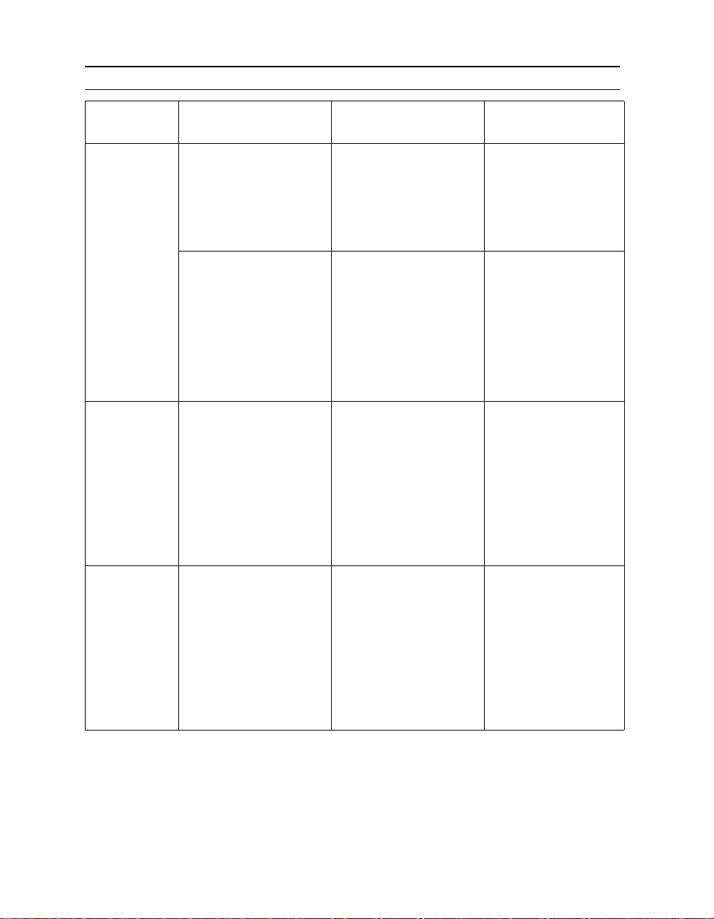
Table 1 Paper Handling Configuration Examples
Printer and
Environment
D640, no HCI
Many users
D640, HCI
Many users
D640, one
user,
preprinted
forms
Result D640 Control Panel npconfig.pub.sys
• Duplex printing on plain
paper
• MPE/iX banner page at
beginning and end of each
job
• Duplex printing on plain
paper
• MPE/iX banner page at
beginning of each job,
printed on green paper.
• No end banner.
• Duplex printing on plain
paper
• Legal and Ledger paper
available
• MPE/iX banner page at
beginning of each job,
printed on blue paper
• No end banner
• Simplex printing on preprinted forms
• No banner page at beginning or end
• No job separation
T est alignment and verify that
forms work before production
run.
intray = TRAY1
traylock.tray1 = UNLOCKED
traylock.tray2 = UNLOCKED
traylock.tray3 = UNLOCKED
duplex = ON
jamrecovery = ON
jobseparate = NONE
intray = TRAY2
traylock.tray1 = LOCKED
traylock.tray2 = UNLOCKED
traylock.tray3 = UNLOCKED
duplex = ON
jamrecovery = ON
jobseparate = NONE
Put green paper in tray1,
white in tray2 and tray3
intray = HCI
traylock.tray1 = LOCKED
traylock.tray2 = UNLOCKED
traylock.tray3 = UNLOCKED
duplex = ON
jamrecovery = ON
jobseparate = NONE
Put blue letter paper in tray1,
ledger in tray2, legal in tray3,
white letter in HCI
intray = TRAY1
traylock.tray1 = UNLOCKED
traylock.tray2 = UNLOCKED
traylock.tray3 = UNLOCKED
duplex = OFF
jamrecovery = ON
jobseparate = NONE
Put forms in trays face down,
with top of form toward
printer rear.
jam recovery = TRUE
banner_header = TRUE
banner_trailer = TRUE
data_intray = 1
banner_intray = 1
jam recovery = TRUE
banner_header = TRUE
banner_trailer = FALSE
data_intray = 4
banner_intray = 1
jam recovery = TRUE
banner_header = TRUE
banner_trailer = FALSE
data_intray = 5
banner_intray = 1
jam recovery = TRUE
banner_header = FALSE
banner_trailer = FALSE
data_intray = 1
banner_intray = 1
Chapter 2: Printing Options 7
Page 14

Edge to Edge Printing
Typically, the D640 printer enforces a 1/6" unprintable area around
the edge of any page. This is the factory default and produces the
best looking output. There may be some cases where you don’t want
this border. The D640 supports edge-to-edge printing which allows
you to extend printing to the edge of the physical page.
Note The print quality is not consistent within 1/6" of any edge. This is
especially true for the trailing edge of the second side in duplex printing.
For this reason, Hewlett-Packard cannot guarantee print quality within
this 1/6" area. Your Hewlett-Packard warranty and service contract
does not cover service calls related to printing within this 1/6" area.
The quality and squareness of the paper determine print quality when
printing close to the physical paper edge. In general, you may
experience degraded print quality within 0.25 inches of any paper
edge. When printing in duplex you may need to compensate for
shrinkage and curl that may occur when the first side is printed.
Lighter weight and recycled papers tend to shrink more than heavier
weight paper.
For edge-to-edge printing, first turn off the clip setting in the
Configuration Menu or send the appropriate PJL command. Then, set
the logical page size to the physical page size using PCL commands.
(See example below.)
@PJL SET CLIP=OFF<EOL> ;allow printing near edges
<ESC>%-12345X
<ESC>%-12345X@PJL ENTER LANGUAGE=PCL<EOL>
<ESC>E
<ESC>&l6A ;select ledger size
<ESC>&a10W ;define page to be edge-to-edge
0x00 0x00 ;left offset is 0
0x00 0x00 ;top offset is 0
0x01 0x00 ;orientation is landscape
0x2F 0xD0 ;width is 0x2FD0 decipoints
0x1E 0xF0 ;height is 0x1EF0 decipoints
<ESC>&l0E ;set top margin to 0
<ESC>&a0L ;set left margin to 0
8 Chapter 2: Printing Options
Page 15
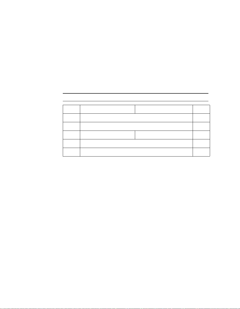
If you define text to start printing at location 0,0 it will print off of the
logical page. This may or may not be on the physical page. Figure 1
describes the physical and logical page formats.
The following escape sequence allows you to define the logical page:
<ESC> & a # W[binary data]
Where # is the number of bytes of binary data following the
terminator.
The default value for # is = NA.
The range for # is = 4,10.
The binary data describes the logical page format as shown below:
Table 2 Logical Page Format
Byte 15 (MSB) 8 7 0 (LSB) Byte
0 Left Offset 1
2 Top Offset 3
4 Orientation Reserved (0) 5
6Width7
8 Height 9
Left Offset Specifies (in integer decipoints) the location of the left
edge of the logical page with respect to the left side of the physical
page in the selected viewing orientation. The range of values is
-32767 to 32767.
Top Offset Specifies (in integer decipoints) the location of the top
edge of the logical page with respect to the top edge of the physical
page in the selected viewing orientation. The range of values is
-32767 to 32767.
Orientation This is the viewing orientation of the logical page with
respect to the physical page. Values may be 0 (portrait), 1
(landscape), 2 (reverse portrait), or 3 (reverse landscape). All other
values reset the logical page definition leaving the logical page as it
was previously defined.
Reserved Byte A byte which must be present in the data stream
and must be equal to zero.
Width Logical page width is defined in decipoints. A zero width
causes the logical page definition to be ignored. The logical page may
be larger than the physical page. The range of values is 1 to 65535.
Chapter 2: Printing Options 9
Page 16

Height Logical page height is defined in decipoints. A zero height
causes the logical page definition to be ignored. The logical page may
be larger than the physical page. The range of values is 1 to 65535.
Either 4 or 10 bytes of binary data defining values in the specified
range must be downloaded with this command. If more than 10 bytes
are received, the excess number is disregarded. If the number of
bytes received is less than 10 and greater than 4, the left and top
offsets are changed and the remaining bytes are ignored.
Upon receipt of a valid, 4-byte command, the current logical page
definition is updated with the new left and top offsets. The margins,
print direction, and current active position (CAP) are retained relative
to the new position of the logical page. (The only change to the
current logical page is that now it is offset relative to the physical
page.)
Upon receipt of a valid command with 10 or more bytes of binary
data, the current logical page definition is discarded and the new
definition is installed. The following actions take place with a new
definition:
The macro overlay is disabled.
l
Any current raster graphics are closed.
l
The primary and secondary fonts are set for the selected
l
orientation.
Print direction is set to zero and the orientation is set
l
appropriately.
HMI, VMI, margins, and text length are set to their PCL defaults.
l
CAP is moved to (0,0).
l
CAP becomes floating.
l
The reference point used for tiling defaults to the upper-left corner of
the current logical page. The tiles are printed based on the viewing
orientation selected.
The picture frame is defaulted to the logical page bounds and the
l
anchor point is set to the upper left corner of the logical page.
Any extra bytes specified with the command are disregarded.
l
The positions stored in the CAP stack are not changed with an
l
orientation change. Therefore, the positions are relative to the top
left corner of the current orientation.
10 Chapter 2: Printing Options
Page 17
The new logical page definition remains in effect until another
l
logical page is defined, or the logical page is defaulted by receipt
of a reset, an orientation change, a page length, or a paper size
command. The current logical page definition (PCL default or
user defined) is part of the user and overlay environments. A
graphic mark will appear on the page if and only if it falls within
the printable area and the logical page boundaries. For HP-GL/2
mode, graphics must also be within the defined picture frame and
user defined window.
Figure 1 Physical Page Formats
Chapter 2: Printing Options 11
Page 18
Working with Multiple Copies
You can print multiple copies of a document using the following
methods:
setting the printer’s control panel
l
(Copies, Mopies, and Auto-collate)
using commands in a print job
l
For more information on setting the printer’s control panel to create
multiple copies, see the
User Manual
To specify multiple copies in a print job, use the following commands:
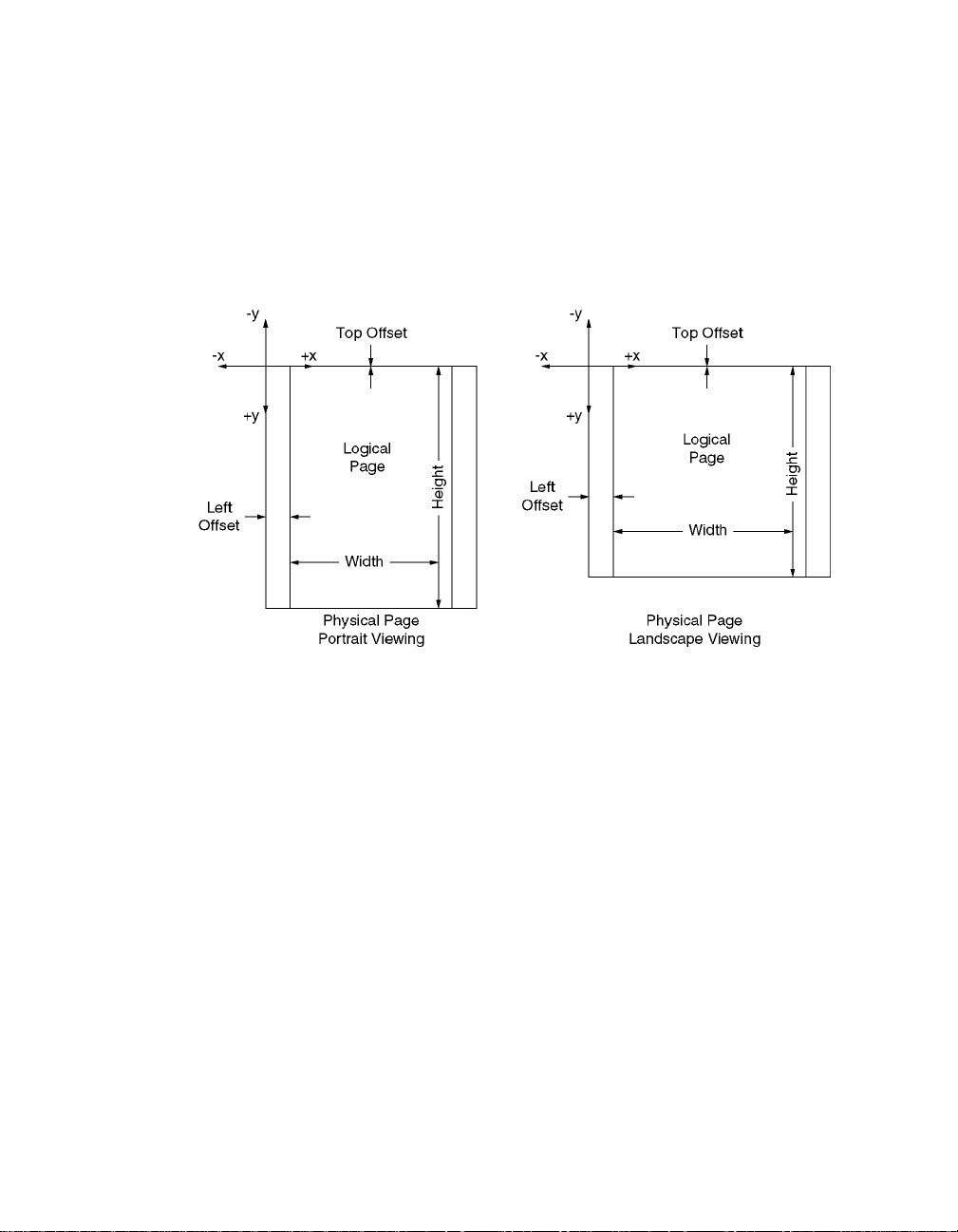
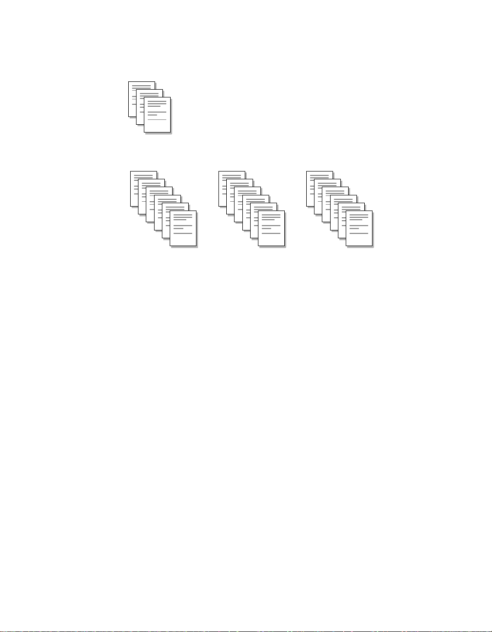
Table 3 Commands for Multiple Copies
PJL SET COPIES = n Where n is the number of copies specified for each page of a
document. Copies are created on a page -by-pag e basis . Each pa ge is
printed n times. See illustration below.
PJL SET QTY = m Where m is the number of collated copies (mopies) spec ified for the
document. Copies are created on a document-by-document basis. A
completed document is printed m times. See illustration below.
.
Multiple-page document
1
2
3
PJL SET COPIES = 2
1
1
2
2
3
3
PJL SET QTY = 2
1
2
3
1
2
3
12 Chapter 2: Printing Options
Page 19
If you combine the PJL SET COPIES and PJL SET QTY commands
in the same print job (and the auto-collate setting on front of the
printer is off), the result is multiplicative. See illustration below.
PJL SET COPIES = 2
PJL SET QTY = 3
1
2
3
3 sets of documents are created.
Each set has 2 copies of each page.
1
1
2
2
3
3
1
1
2
2
3
3
1
1
2
2
This combination of copies and mopies is useful if you’re simulating a
multi-part form on the printer and you want multiple copies of the
form.
CCITT Groups 3 and 4 Decompression
The D640 printer supports CCITT Groups 3 and 4 image
decompression, commonly used for faxing data and images. You can
send the printer these printer-specific commands and data
compressed using CCITT Groups 3 and 4. The printer decompresses
and prints the data.
Three new modes for transfer raster data are supported:
<ESC>*b#M
6 - CCITT G3 one-dimensional (modified Huffman)
l
7 - CCITT G3 two-dimensional (modified Read)
l
8 - CCITT G4 two-dimensional (modified Read)
l
3
3
The first four bytes of this command are a 32-bit unsigned integer that
specifies the number of pixels per row. If these bytes are inadvertently
transposed, the image may appear to be one long row of pixels.
Most standard PCL5 raster image commands, excluding Y offset
<ESC>*b#Y commands, work with the new printer-specific command
extensions.
Chapter 2: Printing Options 13
Page 20

If possible, identify the compression method used on the data you’ll
be decompressing and printing. With this information, you can more
accurately select values for the printer-specific commands. If you
cannot identify the type of compressed data, you will have to
experiment with the commands when trying to decompress and print
the image.
You may encounter CCITT compressed data where the data is
reversed. For example, the first four bytes of the data file should
contain a value representing the width of the image in pixels per row.
A typical value might be Ox: 00 00 01 98, indicating a width of 408
pixels. If the bytes were swapped into “little endian” order, they would
appear as Ox: 01 98 00 00, which would indicate a very wide picture.
The D640 supports a resolution of 200 dpi, so images scanned at this
resolution print at their normal size.
Image Position
The decompressed image will be placed within the PCL 5 default
margins unless edge-to-edge printing is selected. Use the printerspecific edge-to-edge commands, along with the following cursor
positioning command:
<ESC>*p0x0Y cursor position at 0, 0
Table 4 Image Position
Command Action
<ESC>*r0F presentation mode zero
<ESC>*t300R 300 dpi resolution
<ESC>*r800T image height = 800
<ESC>*r1664S image width = 1664
<ESC>&l0O portrait orientation
<ESC>*r1A use current cursor position
<ESC>*b8M use CCITT4 Group 4 (MMR) decompression mode
<ESC>*b9604W raster block data length = 9604 bytes
<data> raster data
<ESC>*rC end raster image
14 Chapter 2: Printing Options
Page 21

LaserJet Compatibility
The D640 printer is unique and different from the Hewlett-Packard
LaserJet family of printers in general, and from the LaserJet “Si”
series in particular. While these two printer families share the same
printer language (PCL and PJL), there are a number of physical
differences to their hardware.
Hewlett-Packard has included features in the D640 printer to make it
behave like a LaserJet 4Si, so your print jobs turn out like you would
expect them to if you were printing to a 4Si. In many instances these
features also provide compatibility with other LaserJet products such
as the IIISi and/or 5Si.
This section covers the compatibility features associated with PCL
commands.
Paper Input
The D640 has three paper input trays, while the LaserJet 4Si has two,
and the LaserJet5Si has three.
The IIISi and 4Si printers have a high-capacity input (HCI) unit
available as an option. Jobs set up for this environment use the PCL
<ESC>&l4H command to se lect the HCI. The sa me command sele cts
tray2 on the D640.
HCI selection compatibility is provided through the HCI-Alias Control
Panel setting. HCI-Alias enables paper selection compatibility
between a LaserJet IIISi (or 4Si) with an HCI and a D640 with an HCI.
With HCI-Alias = tray2 (normally the LaserJet 4Si’s high capacity
input) the PCL command <ESC>&l4H causes the D640 to pick paper
from the HCI. You can also set HCI-Alias = HCI to pick paper from
tray1, tray2, tray3, or the HCI in response to the PCL commands
shown in Table 5.
Chapter 2: Printing Options 15
Page 22

Example Configuration
LaserJet IIISi / 4Si
UPPER TRAY contains paper for job separation.
l
HCI TRAY contains white paper.
l
This configuration provides 500 sheets in the upper tray
(<ESC>&l1H), and 1500 sheets in the HCI tray (<ESC>&l4H). To
match this configuration on the D640, set up the D640 as follows:
TRAY1 contains paper for job separation.
l
HCI contains white paper.
l
Set HCI-Alias = tray2.
l
This configuration provides 500 sheets in tray1 (<ESC>&l1H), and
3000 sheets in the HCI (<ESC>&l4H). You could also load paper for
job separation in tray2 and tray3 to increase capacity to 1500 sheets.
If HCI-Alias is set to HCI, the values shown below in Table 5 are
correct. If HCI-Alias is set to tray2, then you can send a job to either a
4Si or a D640.
Table 5 Tray Map for HCI-Alias = HCI
PCL IIISi, 4Si D640 5Si
<ESC>&l1H upper tray upper tray (tray1) upper tray (tray2)
<ESC>&l4H
<ESC>&l5H
<ESC>&l8H
lower tray middle tray (tray2)
n/a High Capacity Input High Capacity Input
n/a lower tray (tray3) fold out tray (tray1)
lower tray (
tray3)
You can also set the default paper tray (used if there is no paper size
or paper source command embedded in the print job) from the
Control Panel or via PJL commands. Use the intray setting in the
Printing Menu, or the PJL command:
@PJL SET MEDIASOURCE=TRAY1
(or TRAY2 or TRAY3 or HCI)
16 Chapter 2: Printing Options
Page 23
Paper Output
Refer to the tables below to convert jobs from the 4Si or 5Si to the
D640.
Table 6 D640, 4Si, 5Si Output Paper Tray PCL Map
PCL 4Si D640 5Si
<ESC>&l1G top, face down top, face down top, face down
<ESC>&l2G
<ESC>&l3G
<ESC>&l4G
<ESC>&l5G
<ESC>&l6G
back, face up HCO, face down left side, face up
(not with HCO)
n/a HCO, face up HCO, face up
n/a N/A HCO #1, face down
n/a N/A HCO #2, face down
n/a N/A HCO #3, face down
Table 7 D640, 4Si, 5Si Output Paper Tray PJL Map
PJL Outbin 4Si D640 5Si
UPPER top, face down top, face down top, face down
LOWER
HCO-D n/a HCO, face down n/a
HCO-U n/a HCO, face up n/a
OPTIONAL
OUTPUTBIN1
OPTIONAL
OUTPUTBIN2
OPTIONAL
OUTPUTBIN3
back, face up N/A left side, face up
(not with HCO)
n/a N/A HCO #1, face down
n/a N/A HCO #2, face down
n/a N/A HCO #3, face down
Chapter 2: Printing Options 17
Page 24

Internal Fonts
Each of th e D640 inte rnal f onts is alm ost id entica l to t hose used i n the
LaserJet 4Si. Due to advances in font technology since the
development of the 4Si, some typefaces, treatments, and symbol sets
are slightly different. (For example, if you print a very large question
mark on each printer, you may notice differences in the shape.)
Each of the D640 printer’s 56 virtual font cartridges is almost identical
to the corresponding font cartridge sold for the LaserJet IIISi and 4Si
printers.
See Chapter 6 for more information about D640 fonts and virtual font
cartridges.
18 Chapter 2: Printing Options
Page 25

Working with TIFF
3
Images
About TIFF Images
The D640 printer supports TIFF emulation which enables your printer
to recognize and print bi-level, monochrome TIFF images. Previously,
TIFF images had to be part of a larger PCL or PostScript (PS)
document to be printed.
TIFF support for the D640 printer conforms to the specifications
described in
1992. The information in this chapter assumes you are familiar with
TIFF Revision 6.0
The D640 printer supports relevant parts of Baseline TIFF and
selected elements of Extended TIFF. There are no private fields or
values required by the printer.
TIFF Revision 6.0
published by Aldus Corporation, June
.
Note The TIFF standard does not contain any elements to indicate the
termination of data. Therefore, termination of a TIFF file must be
indicated by PJL universal escape sequences or the printer’s I/O
timeout configuration.
Printing TIFF Images
TIFF images can be printed using the following methods:
l setting the printer’s control panel to recognize TIFF files
(Emulation = TIFF or Auto). Auto is the recommended setting if
you print files using more than one protocol (such as PCL or PS).
l using commands in a print job
Chapter 3: Working with TIFF Images 19
Page 26

Using the Control Panel
On the printer’s control panel, you can explicitly select TIFF
emulation. For details, see the
User Manual
.
When TIFF emulation is set, the following data items are valid:
A new TIFF file, starting with a 4-byte sequence $49492A00 or
l
$4D4D002A
PJL commands
l
Any other type of data is treated as an error.
On the printer’s control panel, you can also use the Auto emulation
setting to implicitly recognize TIFF files.
If Auto emulation is set, the printer recognizes either of the following
sequences as valid TIFF file headers and enters TIFF emulation
mode automatically, if this sequence is at the start of the print job.
$49492A00 or $4D4D002A
l
Using Commands in a Print Job
In addition to control panel settings, TIFF protocol can be selected by
the PJL command:
@PJL ENTER LANGUAGE = TIFF
The following is a sample print job for a TIFF file:
<ESC>%-12345X@PJL JOB NAME="Sample.tif"<LF>
<ESC>%-12345X@PJL SET CLIP=OFF<LF>
<ESC>%-12345X@PJL ENTER LANGUAGE=TIFF<LF>
< tif file goes here >
<ESC><ESC><Bel>
<ESC>%-12345X@PJL<LF>
@PJL EOJ NAME="Sample.tif"<LF>
<ESC>%-12345X
20 Chapter 3: Working with TIFF Images
Page 27

General Rules
The following are some general rules to describe how the D640
printer processes TIFF data.
Each TIFF file is a self-contained unit, made up of one or more
l
sub-files. Each sub-file describes a single rectangular image. The
image may be a complete page, or it may be a part of a page.
During TIFF emulation, the printer cannot switch into any other
protocol, except at the boundaries of individual TIFF files.
If a TIFF image contains multiple sub-files, the images contained
l
in the sub-files are placed on separate pages in the order the
sub-files appear in the TIFF data stream.
If TIFF is the selected protocol:
l
• Images are placed with respect to the physical page, with zero
margins.
• If a sub-file doesn’t have positioning information, the image is
placed at the edge of the page.
• If a sub-file has positioning information, the commands are
interpreted as absolute displacements from the edge of the
physical page.
• The Clip setting for the document determines if the image is
printed to the edge of the page.
This can be a common
situation. TIFF documents are often created to take up the
entire page. To prevent
clipping of the image
when you print, make
sure
Clip = Off is set in the
Configuration menu.
For best resul t s, t ry
This can be a common
situation. TIFF documents are often created to take up the
entire page. To prevent
clipping of the image
when you print, make
sure
Clip = Off is set in the
Configuration menu.
For best results, try
Clip = On Clip = Off
Chapter 3: Working with TIFF Images 21
Page 28

TIFF was designed as a file structure for random-access devices.
l
When used as a printer protocol, HP recommends the following
ordering restrictions apply to allow sequential processing of the
data. These include:
• Offset values should be greater than the file position of the
offset. For example, If an offset resides at file position A within
the TIFF data, its value should be greater than A.
• Within a file, all tag fields pertinent to the image should precede
the image data.
• The ordering of components within each sub-file should be:
- Image file directory
- Data values identified by directory entry offsets
- Image data.
See page 23 for some example TIFF structures.
22 Chapter 3: Working with TIFF Images
Page 29
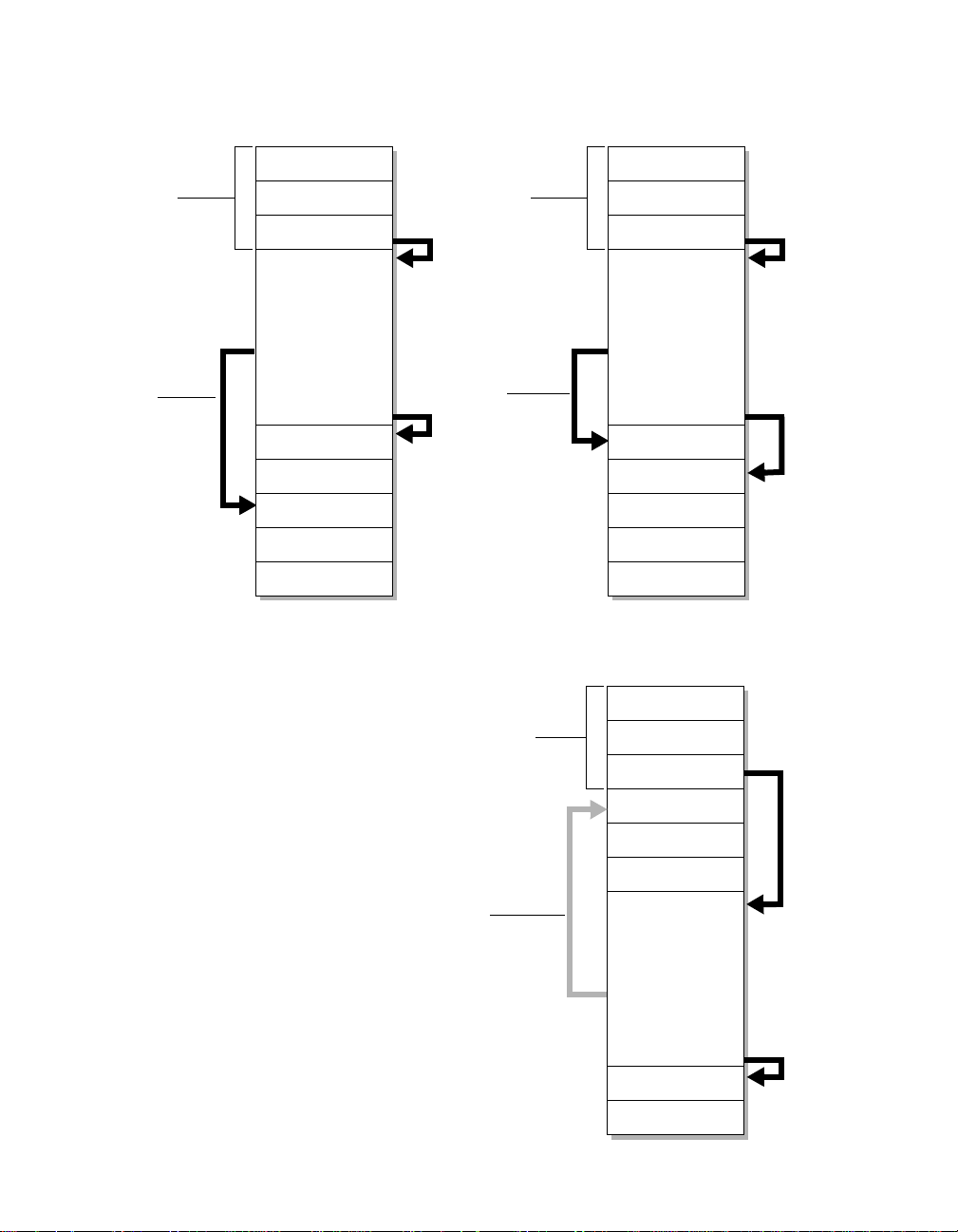
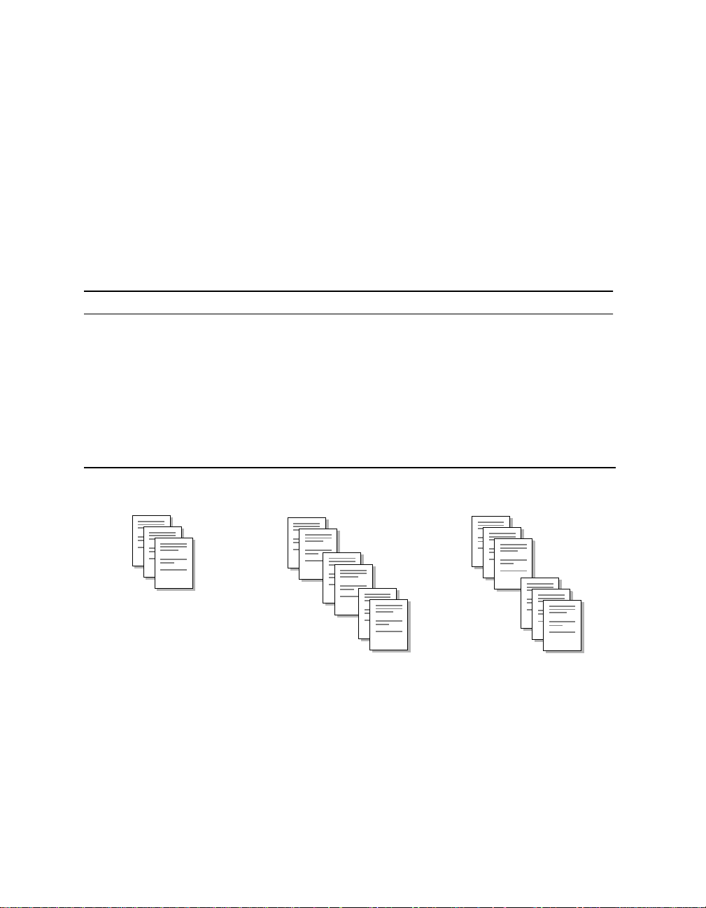
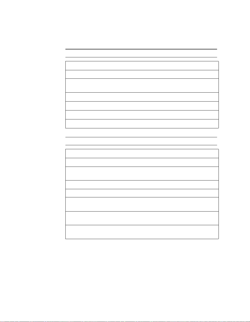
Preferred structure of a TIFF file: In Example 1 and Example 2, all the image file directories
occur early in the file. This is a good structure for TIFF files sent to the D640 printer.
Image file
header
Forward
pointers are
best
Example 1
II or MM
0x2A00 or 0x002A
Pointer to first image
file in directory
Image File Directory 0
Number of en tries
Entry # 1
Entry # 2
Entry #3
Pointer to Image Data
...
Size of Image Data
...
Entry #n
Pointer to next IFD
Image File Directory
Image file
header
Forward
pointers ar e
best
Example 2
II or MM
0x2A00 or 0x002A
Pointer to first image
file in directory
Image File Directory 0
Number of entries
Entry # 1
Entry # 2
Entry #3
Pointer to Image Data
...
Size of Image Data
...
Entry #n
Pointer to next IFD
Image Data
Image File Directory
Image Data
Image Data
Image Data
Alternative structure for a TIFF file:
In the structure below, the image file directories appear
Image File Directory
Image Data
Image File Directory
Image Data
after the image data. This file may not be printable because of the backward pointer. With this structure, the
D640 printer can handle only small TIFF files (one small image).
Image file
header
Backward pointers
might not work.
(They are not
recommended.)
II or MM
0x2A00 or 0x002A
Pointer to first image
file in directory
Image Data
Image Data
Image Data
Image File Directory 0
Number of entries
Entry # 1
Entry # 2
Entry #3
Pointer to Image Data
...
Size of Image Data
...
Entry #n
Pointer to next IFD
Image File Directory
Image File Directory
Chapter 3: Working with TIFF Images 23
Page 30

Errors
Errors in the TIFF file header or in directory offset values are
considered major errors. The remainder of the TIFF file is ignored and
the print job is abandoned.
For other errors, the processing of the current sub-file continues, but
no image is printed. Subsequent sub-files are processed normally .
The following are the main categories of errors:
Absence of mandatory TIFF fields (directory entries)
l
Duplicate occurrences of tags in one directory
l
Wrong type for a significant TIFF field
l
Wrong number of values for a significant TIFF field
l
Value out of range for a significant TIFF field
l
Offset values less than the file position of the offset (for a
l
significant TIFF field)
If a TIFF field is not significant for the printer, its Type, Number, and
Value are not checked for correctness.
The TIFF specifications (described in
fields to appear in ascending tag order. The D640 printer does not
enforce this requirement.
Note Y ou can use the error report setting on the D640 printer to print a report
of TIFF errors within a print job. See the
information.
TIFF Revision 6.0
User Manual
) require TIFF
for more
24 Chapter 3: Working with TIFF Images
Page 31

TIFF Structure and Fields
This section includes a full list of baseline and extended TIFF fields
with comments on their interpretation by the D640 printer.
The following conventions are used to describe the TIFF fields.
Fields marked with * are significant for the processing of image
l
data by the printer.
Fields marked with ** have no default value. These fields are
l
mandatory. If any of these fields are missing from the TIFF data,
an error occurs.
The first line of the TIFF definition lists the name of the field. The
l
second line provides the tag number in hex, the type of values,
and the number values for the field. For example:
Name
Tag,Type,N
Comments about the field are listed to the right of the field name.
l
Baseline TIFF
The following is a list of extended TIFF fields which are accepted by
the D640 printer.
Table 8 Baseline TIFF Definitions
Structure
Image File Header
Multiple IFDs
Bytes 0-1 in the file can be either $4949 indicating little-endian
data format (Intel standard) or $4D4D indicating big-endian data
format (Motorola standard).
The D640 printer can read multiple IFDs and process multiple
images. Each image is printed on a se parate page.
Baseline fields
Artist
013B,ASCII
Person who created the image.
Chapter 3: Working with TIFF Images 25
Page 32

Table 8 Baseline TIFF Definitions
* BitsPerSample
0102,Short,N
CellLength
0109,Short,1
CellWidth
0108,Short,1
ColorMap
0140,Short,3*2^bps
* Compression
0103,Short,1
Numbers of b its for individual color co mponents.
The D640 printer is monochrome. Therefore, N=1 , and the value
itself must be 1.
Default = 1.
The length of the dithering or halftoning matrix used to create a
dithered or halftoned bi-level file. The printer does not generate
its own halftoning.
The width of the dithering or halftoning matrix used to create a
dithered or halftoned bi-level file.
A Red-Green-Blue color map for palette color images.
Compression scheme used for the image data. The following
compression modes are supported by the D640 printer:
baseline TIFF
1 = No compression. Data packed tightly into bytes, but not
spanning row boundaries. This is the default.
2 = CCCIT Group 3, 1-dimensional, modified Huffman run-
length encoding.
32773 = PackBits compression. A byte-oriented, run-length
encoding scheme.
extended TIFF
3 = T4-encoding (Group 3, 2-dimensional). CCITT T.4 bi-
level encoding (Geneva: 1988).
4 = T6-encoding (Group 4). CCITT T.6 bi-level encoding
(Geneva: 1988).
Copyright
Copyright notice.
8298,ASCII
DateTime
0132,ASCII,20
Date and time in the following format: YYYY:MM:DD HH:MM:SS
A null (binary zero) terminates the string.
26 Chapter 3: Working with TIFF Images
Page 33

Table 8 Baseline TIFF Definitions
ExtraSamples
0152,Short,m
* FillOrder
010A,Short,1
FreeByteCounts
0121,Long,1
FreeOffsets
0120,Long,1
Description of extra components.
The logical order of bits within a byte.
Default =1
For value 1, pixels with low column values are stored in highorder bits of the byte. The most significant bit in a byte is the
earliest in the raster line for uncompressed data as well as the
earliest in compression code for compressed data.
For value 2, pixels with low column values are stored in low-order
bits of the byte.
Both values are supported, but Hewlett-Packard recommends
using FillOrder=1 for performance.
For each string of contiguous unused bytes in a TIFF file, the
number of bytes in the string.
The presence of unused bytes is not recommended.
For each string of con tiguous u nused byt es in a TIFF fi le, the byt e
offset of the string.
GrayResponseCurve
0123,Short,2^bps
GrayResponseUnit
0122,Short,1
HostComputer
For grayscale data, the optical density of each possible pixel
value.
The precision of the information contained in the
GrayResponseCurve.
The computer and/or operating system used to create the image.
013C,ASCII
ImageDescription
A string that describes the subject of the image.
010E,ASCII
** ImageLength
The number of rows of pixels in the image.
0101,Short/Long,1
** ImageWidth
The number of columns in the image (p ixels per row).
0100,Short/Long,1
Chapter 3: Working with TIFF Images 27
Page 34

Table 8 Baseline TIFF Definitions
Make
The scanner manufacturer.
010F,ASCII
MaxSampleValue
The maximum component value used.
0119,Short,Sampl/Pix
MinSampleValue
The minimum component value used.
0118,Short,Sampl/Pix
Model
The scanner model name and number.
0110,ASCII
* NewSubfileType
A general indication of the kind of data contained in this sub-file.
00FE,Long,1
03103002902802702602502402302202102001901801701601501401301201101009080706050403Tr2MP1Red
Red = 1 Reduced-version of another image in the same file.
MP = 1 Page of multi-page document.
Tr = 1 Transparency mask of another image in the same file.
0
If either Red or Tr is set, the image is ignored by the
printer.
Default = 0.
28 Chapter 3: Working with TIFF Images
Page 35

Table 8 Baseline TIFF Definitions
* Orientation
0112,Short,1
The orientation of the image with respect to the rows and
columns.
Default = 1.
1 0th row is the visual top and 0th column is the visual left of
the image.
2 0th row is the visual top and 0th column is the visual right of
the image.
3 0th row is the vi sual b otto m and 0th co lumn is the visu al ri ght
of the image.
4 0th row is the visual bottom and 0th column is the visual left
of the image.
5 0th row is the visual left and 0th column is the visual top of
the image.
6 0th row is the visual right and 0th column is the visual top of
the image.
7 0th row is the visua l right and 0t h c olumn is the visual bot tom
of the image.
8 0th row is the visual left and 0th column is the visual bottom
of the image.
** Photomet ricInterpretation
0106,Short,1
PlanarConfiguration
The color space of the image data. Only the two values below are
accepted.
0 WhiteIsZero: 0 is imaged as white, 1 is imaged as black.
1 BlackIsZero: 0 is imaged as black, 1 is imaged as white.
How the components of each pixel are stored.
011C,Short,1
* ResolutionUnit
0128,Short,1
The unit of measurement for XResolution and YResolution.
Default = 2.
1 No absolute unit of measurement.
2Inch
3 Centimeter
Chapter 3: Working with TIFF Images 29
Page 36

Table 8 Baseline TIFF Definitions
* RowsPerStrip
0116,Short/Long,1
*SamplesPerPixel
0115,Short,1
Software
0131,ASCII
** StripByteCounts
0117,Short/
Long,StripsPerIma ge
The number of rows per strip. The default is the v alue given b y
ImageLength resulting in a single-strip image.
Image data may be broken into a number of strips or bands.
However, for the D640 printer, single strips are preferable.
The value of RowsPerStrip together with the value of
ImageLength determines the number of strips in the image:
StripsPerImage = ImageLength/RowsPerStrip (rounded up)
Default = ImageLength (single strip).
The number of components per pixel.
Any value other than 1 is treated as an error.
Default = 1.
Name and version number of the software package used to
create the image.
For each strip, the number of bytes in the strip after compression.
This field is mandatory, except for uncompressed data, where it
can be computed from ImageWidth and RowsPerStrip.
** StripOffsets
For each strip, the byte offset of that strip.
0111,Short/
Long,StripsPerIma ge
SubfileType
00FF,Short,1
Threshholding
0107,Short,1
As with other offsets, the offsets are specified with respect to the
beginning of the TIFF file. For the D640 pri nter, HP recommends,
they be in ascending sequ ence and do no t have a value less than
the file position of the offset.
An indication of the kind of data contained in this sub-file.
Recognized but not used (obsolete).
For black and white TIFF files that represent shades of gray, the
technique used to convert gray to black and white pixels.
30 Chapter 3: Working with TIFF Images
Page 37

Table 8 Baseline TIFF Definitions
** XResolution
011A,Rational,1
** YResolution
011B,Rational,1
The number of pixels per ResolutionUnit in the horizontal
(ImageWidth) direction.
If the resolution specified is not the same as the currently
selected printer resolution (200, 300, or 600 dpi), the image data
may be scaled in the horizontal direction by the ratio of printer
resolution to specified resolution.
For Group 3 and Group 4 compression modes (compression = 2,
3, or 4), scaling is performed for all ratios, w hether scaling up
(expanding the data) or scaling down (reducing the data).
For uncompressed data (compression =1) or PackBits
compression (compression = 32773), scaling down is not
performed, and scaling up is confined to ratios 2, 3, 4, 6 and 8.
Other ratios are treated as the nearest lower ratio. Ratios less
than 2 are treated as 1 (no scaling).
The number of pixels per ResolutionUnit in the vertical
(ImageLength) direction.
If the resolution specified is not the same as the currentlyselected printer resolution (200, 300, or 600 dpi), the image data
is scaled in the vertical direction as described above for
XResolution.
Chapter 3: Working with TIFF Images 31
Page 38

Extended TIFF
The following is a list of extended TIFF fields which are accepted by
the D640 printer. The additional compression modes 3 and 4 are
listed in the Baseline TIFF section on page 26.
Table 9 Extended TIFF Definitions
T4Options
0124,Long,1
03103002902802702602502402302202102001901801701601501401301201101009080706050403Fill2Unc12D
A vector of 32 flag bits which set parameters for T4-encoding.
Unused bits must be 0. Default =0.
2D = 0 1-dimensional coding is used.
2D = 1 2-dimensional coding is used. If more than one strip is
specified, each strip m ust begin with a 1-dimensionally
coded line.
Unc = 0 Uncompressed mode is not allowed.
Unc = 1 Uncompressed mode is allowed.
The D640 printer does not support uncompressed mode
within compressed data. Setting of this bit is treated as
an error.
Fill = 0 No fill bits.
Fill = 1 Fill bits have been added as necessary before EOL
codes such that EOL always ends on a byte boundary.
T6Options
0125,Long,1
A vector of 32 flag bits which set parameters for T6-encoding.
Unused bits must be 0.
0
0310300290280270260250240230220210200190180170160150140130120110100908070605040302Unc10
0
Unc = 0 Uncompressed mode is not allowed.
Unc = 1 Uncompressed mode is allowed.
The D640 printer does not support uncompressed mode
within compressed data. Setting of this bit is treated as
an error.
Default = 0.
DocumentName
The name of the document from which the image was scanned.
010D,ASCII,1
32 Chapter 3: Working with TIFF Images
Page 39

Table 9 Extended TIFF Definitions
PageName
011D,ASCII,1
PageNumber
0129,Short,2
* XPosition
011E,Rational,1
* YPosition
011F,Rational,1
The name of the page from which the image was scanned.
The page number of the page from which the image was
scanned. PageNumber_0 is the page number, with the first page
numbered 0. PageNumber_1 is the total number of pages in the
document. If PageNumber_1=0, the total number of pages in the
document is not available.
X offset in ResolutionUnits of the left side of the image (with
respect to the left side of the page).
Honored only when within the physical page.
Y offset in Res olutionU nits of th e top of th e image (wit h resp ect t o
the top of the page).
Honored only when within the physical page.
Unsupported Functions
The D640 printer does not support:
• Grayscale images
• Palette-color images
• RGB full-color images
• Tiled images
• CMYK images
• HalfTone hints
• Alpha data handling
• Data sample format
• RGB image colorimetry
•YC
bCr
images
• JPEG compression
• CIE L*a*b* images
Chapter 3: Working with TIFF Images 33
Page 40

TIFF Images as Part of PCL
Introducing PCL Compression Method 10
The PCL Compression Method command (<ESC>*b#M) determines
how raster data is interpreted for the Transfer Raster Data by Row/
Block command (<ESC>*b#W). The selected compression method
stays in effect until explicitly changed by another PCL Compression
Method command (<ESC>*b#M) or until it is reset by an End Raster
Data command (<ESC>*rC).
See table below for a list of compression methods.
Table 10 List of Compression Methods
0 Uncompressed (row-based)
1 Run-length encoding (row-based)
2 TIFF rev 4.0 “PackBits” encoding (row-based)
3 Delta row encoding (row-based)
4 Unencoded (block-based)
5 Adaptive encoding (block-based)
6 CCITT G3 one-dimensional encoding (block-based)
7 CCITT G3 two-dimensional encoding (block-based)
8 CCITT G4 encoding (block-based )
10 Tagged Image File Format (TIFF) rev 6.0 (block-based)
PCL Compression Method 10 is useful when you have a
monochrome graphic you want to include as an illustration on a page
with PCL text. The actual format of accepted data is described in
“TIFF Structure and Fields” on page 25.
34 Chapter 3: Working with TIFF Images
Page 41

To include an illustration, transfer the entire TIFF file as a block,
including the header. For example, if the TIFF file is 23,476 bytes in
size, the raster transfer command would be <ESC>*b23476W.
The TIFF file can be little-endian (from a PC) or big-endian (from
HP-UX).
Note Only the first image from the TIFF data is printed, any others will be
ignored.
The image is rendered as the TIFF file describes it, and then the
image is clipped (not scaled) to the boundaries specified by the PCL
commands for raster width and height. Furt her, the image will be
treated just as any other PCL raster image when used with the
Transparency Modes.
Chapter 3: Working with TIFF Images 35
Page 42

Transparency mode with TIFF
Pattern
Source
Destination
The D640 printer enables you to fill images and characters with any
of the printer’s predefined (or user-defined) shading or cross-hatch
patterns and apply them to a destination TIFF image.
The following illustrations shows the effects of the source and pattern
transparency modes on the final image.
Table 11 Effect of transparency mode on images
Images and
patterns
Transparency mode settings Results
Source Transparency Mode = 0 (transparent)
Pattern Transparency Mode = 0 (transparent)
Source Transparency Mode = 0 (transparent)
Pattern Transparency Mode =1 (opaque)
Source Transparency Mode = 1 (opaque)
Pattern Transparency Mode = 0 (transparent)
Source Transparency Mode = 1 (opaque)
Pattern Transparency Mode = 1 (opaque)
36 Chapter 3: Working with TIFF Images
Page 43

Table 12 Effect of transparency mode on text, raster images, and area fill
Area fill
Raster
Scaled
Text
Source images Transparency mode settings Results
Source Transparency Mode = 0 (transparent)
Pattern Transparency Mode = 0 (transparent)
Source Transparency Mode = 0 (transparent)
Pattern Transparency Mode =1 (opaque)
Chapter 3: Working with TIFF Images 37
Page 44

Table 12 Effect of transparency mode on text, raster images, and area fill
Area fill
Raster
Scaled
Text
Source images Transparency mode settings Results
Source Transparency Mode = 1 (opaque)
Pattern Transparency Mode = 0 (transparent)
Source Transparency Mode = 1 (opaque)
Pattern Transparency Mode = 1 (opaque)
38 Chapter 3: Working with TIFF Images
Page 45

Example of PCL compression method 10
Step 1 To fill an image, use the following commands to output the
destination TIFF data.
<ESC>&f0S Push cursor (optional)
<ESC>*v0T Current pattern is black
<ESC>*r#F Raster graphics presentation mode
0 = print direction
3 = along width of page
<ESC>*t#R Raster graphics resolution in dots
per inch
(75, 100, 150, 200, 300, or 600)
<ESC>*r#T TIFF height in raster dots. Dot size is
derived from the <ESC>*r#R command.
# = number of units
<ESC>*r#S TIFF width in raster units
# = number of units
<ESC>*b10M Compression method 10 (entire TIFF data
follows, TIFF header and all data)
<ESC>*r#A Start raster graphics
# = mode
<ESC>*b#W Transfer TIFF data by block
Important
: # = the size of the TIFF file in bytes
<copy TIFF data> Fill in with TIFF data
<ESC>*rC Exit raster mode
<ESC>&f1S Pop cursor (optional, use with
push cursor)
Step 2 Set the source transparency mode.
<ESC>*v#N
Step 3 Output the source raster data or text.
<ESC>*v#T Sets the current pattern (optional)
<include user raster_data or text>
Step 4 Reset the cursor and pattern.
<ESC>*v0T Sets the current pattern to
Black (optional)
<ESC>&f1S Pop cursor (optional)
Chapter 3: Working with TIFF Images 39
Page 46

40 Chapter 3: Working with TIFF Images
Page 47

Using the Printer’s
4
Hard Disk
Data Directories
The D640 contains an internal 1.2GB hard disk drive. It is pre-loaded
with about 80 MB of files. This leaves over 1.1 GB available for the
users.
The D640 has a set of disk and file operation commands that are
compatible with similar commands on other LaserJet products. With
these commands, you can download files containing fonts, macros,
symbol-sets, or complete jobs. Refer to “Commands to Read/Write to
Hard Disk” on page 43 for a detailed reference to these commands.
Printer Data Directories
The pre-loaded files on the hard disk are arranged in these
directories.
USER_ADJ\* User adjustment files called out in the D640 User
Manual
MAINT\* Maintenance tools and data for service purposes.
FONTS\* Factory provided fonts for virtual font cartridges.
User Data Directories
These are preassigned user directories for your downloaded files.
\PCL5\USER\* User downloaded fonts, macros, softpatterns, and
jobs.
\CRT\* Cartridge Definition (.CRT) files.
\PS\USER\* User downloaded PostScript related files.
Chapter 4: Using the Printer’s Hard Disk 41
Page 48

File System Conventions
The D640 printer now includes the following file system conventions.
Long Filenames
The file system for the D640 printer supports a long filename
convention similar (but not identical) to long filenames in
MS Windows.
Long filenames can include any combination of the following:
name stems longer than 8 characters (for example,
l
longername.ext)
extensions longer than 3 characters (for example, name.grp1)
l
names containing more than one extension or dot “.” (for
l
example, name.rev21.tif)
names containing special characters (for example,
l
name:new.user or ?name.+)
Before you create files with long names, consider the following:
HP strongly recommends that characters used in filenames be
l
confined to the ASCII printing set – excluding characters used as
punctuation symbols or wildcards.
The following printing characters are excluded in DOS and MS
Windows:
Operating system Excluded Characters
DOS
Windows 95 or NT
The D640 filing system does not enforce these restrictions.
However, you may encounter problems when protocol
commands refer to filenames with excluded characters.
Files and directories with long filenames have an additional
l
abbreviated name which is DOS-compatible (8.3 characters). In
any context, files and directories may be specified by either the
long name or the abbreviated name.
l The limit on a file or directory name (including all extensions) is
100 characters.
l There is an absolute upper limit of 255 characters on a complete
pathname (including drive specifier).
42 Chapter 4: Using the Printer’s Hard Disk
. " / \ [ ] : ; | = , ? * + < >
" / \ : | ? * < >
Page 49

Other practical constraints, such as the size of fields on the
l
printer’s control panel and in directory listings, should also be
considered.
In terms of storage space and file access speed, long filenames
l
are significantly less efficient than standard names.
Lowercase in Filenames
The D640 printer supports filenames that include both lowercase and
uppercase letters. Filenames are no longer converted to uppercase.
As with MS Windows, case is not significant for matching names. Two
strings which differ only in case are considered to be the same name.
(For example, name.ext and NaME.Ext).
This rule applies to both standard and long filenames.
Default Drive
The default drive is now the printer’s internal hard disk, C: (HDD),
instead of the printer’s floppy disk, A: (FDD).
However, this default should not be assumed. A drive specifier should
always be included to indicate the internal hard drive. Otherwise, this
might lead to incompatibility between printer protocol sent across the
network and printer protocol executed from disk.
Commands to Read/Write to Hard Disk
You can read, write, and delete files on the printer’s hard disk with
PJL commands. Reading from mass storage is different for each
emulation/personality.
Note Currently, there are no security features built into the hard disk filing
system. HP does not recommend storing sensitive files on the internal
hard disk.
Files may contain fonts, macros, symbol-sets, user-defined
l
patterns, or ordinary print data.
l File names can contain up to 100 characters. See “File System
Conventions” on page 42 for a detailed descr iption.
Chapter 4: Using the Printer’s Hard Disk 43
Page 50

Some file extensions have special meaning on the printer. These
l
include:
.HPG HP GL2 file
.CRT Cartridg e definition file
.PCL PCL file
.PS PostScript file
.SFS PCL Softfont in Intellifont form
.SFT PCL Softfont in True Type form
Initialize
This command initializes a floppy diskette for use with the D640.
Diskettes must already be formatted on the PC in IBM-PC compatible
format.
@PJL FSINIT VOLUME = "volume name" <LF>
If a password has been set, it must have been given prior to issuing
this command.
Make Directory on Disk
This command creates a new directory on the floppy diskette.
@PJL FSMKDIR NAME="pathname"<LF>
where pathname is a fully-qualified pathname.
For example:
@PJL FSMKDIR NAME= "C:\PCL5\USER\ACME" <LF>
Only one subdirectory can be created at a time, starting at the
l
highest level in the tree.
Creating a directory doesn’t make it your current working
l
directory.
44 Chapter 4: Using the Printer’s Hard Disk
Page 51

Store a PCL Print File on the Internal Hard Disk
This command stores a file on the printer’s internal hard disk.
@PJL FSDOWNLOAD FORMAT:BINARY SIZE=<integer>
NAME=”pathname”<EOL>
binary data<UEL>
All keywords must be supplied correctly. Thus an <ESC>E or <UEL>
out of place is invalid (and does a reset).
White space may be present on either side of the = sign.
SIZE=integer
Integer is the number of bytes of binary data, expressed as ASCII
digits.
Integer is an integer in the range of 2 to max-signed-int.
NAME="pathname"
Quotes are required to delimit pathname.
The pathname consists of a path (c:\pcl5\...) and a filename.
The pathname must be valid for the file to be stored. Follow DOS
conventions and use .PCL for the extension.
If a file exists already with the same name the user gives, and it is
l
not a “delete-protected” file, the old file is overwritten.
If the data stream gets cut off before the operation completes,
l
then no file is created, and if there was a file of the same name it
may no longer exist; an error could be returned.
The <EOL> is required to indicate that the PJL command ends
l
here and binary data starts in the following byte.
The <UEL> is consumed by the FSDOWNLOAD command; it is
l
not a job boundary, and it is not counted in the SIZE=integer
count.
Chapter 4: Using the Printer’s Hard Disk 45
Page 52

The contents of binary data are not checked by the printer. It is up
l
to you to send valid data. Binary data can contain any number of
<UEL> and or <EOL> chars; they are not a job boundary during
FSDOWNLOAD. If the data does contain <UEL> or <EOL> and
SIZE is not specified correctly, the binary data is parsed as PJL
commands (which might not be desirable). You must make sure
the SIZE is given correctly for the accompanying data stream. If
the SIZE has been given correctly and there is more binary data
supplied, the excess data is ignored. The next PJL command
starts after the first <UEL> command following the binary data.
Once a file is stored on disk, it is available to all subsequent jobs
l
for re-use.
Note Do not store a font or macro with a PCL ID number embedded in it.
The ID number should be assigned by the job stream when it retrieves
the macro from disk.
Recommended Contents of Binary Data
Font PCL soft font format, starting with <ESC>)s#W. It is up to the
application to download fonts using the header format appropriate to
the D640.
Macro PCL macro, starting with <ESC>&f0X (start macro) and
ending with <ESC>&f1X (stop macro). The printer will not append
these PCL commands to the data stream.
Symbol-set A user defined symbol set, starting with <ESC>*c#R
(symbol set ID Code). Although this is the recommendation, the ID
Code could be defined in the job, which would mean that the data
should start with <ESC>(f#W (define symbol set).
Soft pattern A user defined pattern, starting with <ESC>*c#W (user
defined pattern).
Delete a File From Disk
This command removes a file from the printer’s hard disk.
@PJL FSDELETE NAME="pathname" <EOL>
Some notes about this command include:
l White space can be present around the equal sign.
l Quotes must be provided to delimit pathname.
l The pathname is full pathname. No default.
l If the file is a “delete-protected” file, it is not deleted.
46 Chapter 4: Using the Printer’s Hard Disk
Page 53

Using a Disk File in a PCL Job
The Alphanumeric ID command reads a file stored on the hard disk or
floppy disk. With this command, the D640 reads the file into memory
and treats this information as if it was part of the original print job. The
result is similar to an “include” statement in a high-level programming
language.
The D640 does not do any special processing of the file, see
“Recommended Contents of Binary Data” on page 46.
The format of the Alphanumeric ID command is as follows:
<ESC> & n # W [ file identification data ]
# The number of bytes of data that follow the capital W. A value
must be supplied.
[file identification data]
Byte Content
1 Operation Byte (UB)
2
...#File Identifier Name (ASCxx)
Operation Byte (UB) – The Operation Byte is an unsigned byte, which
may have a value 0 through 5. The LaserJet family of printers uses
this byte to indicate whether the file contents are treated as a font or
as a macro. The D640 does not use this byte, but requires the value
to be within the range specified. (The values 0 to 5 are control codes
<SOH>, <STX>, <ETX>, <EOT>, and <ENQ>.)
File Identifier Name (ASCxx) – The File Identifier Name is ASCII data.
The D640 requires the full pathname of the file, including the volume
name. Files and directories can contain the letters A..Z, a..z, and the
numerals 0..9. For example:
C:\PCL5\USER\MyFile.pcl. Do not use
quotation marks around the filename.
Volume P hys ical Devi ce
c: or C: The inter nal hard drive
a: or A: The floppy drive
The PCL commands to manage fonts, macros, patterns, and symbol
sets only act on objects in memory. The disk file can be removed only
with the @PJL FSDELETE command.
In the examples below, <LF> is a line feed, <CR> is carriage return,
<ESC> is the Escape character, and → means that the line is
continued.
Chapter 4: Using the Printer’s Hard Disk 47
Page 54

Example 1:
Storing a Macro on Disk and Using it in a Print Job
Step 1 Write the macro to the hard disk. For example:
<ESC>%-12345X@PJL JOB NAME = "Simple Macro"<LF>
<ESC>%-12345X@PJL FSDOWNLOAD FORMAT:BINARY SIZE=30→
NAME = "C:\PCL5\USER\Macro"<LF>
<ESC>&f0XThis is a test line.<ESC>&f1X<ESC>%-12345X→
<ESC>%-12345X@PJL EOJ NAME = "Simple Macro"<LF>
Step 2 Use the macro in a print job. For example:
<ESC>%-12345X@PJL JOB NAME = "Use Simple Macro"<LF>
<ESC>%-12345X@PJL ENTER LANGUAGE = PCL<LF>
<ESC>E<ESC>&f95Y<ESC>&n19W<0x04>c:\PCL5\USER\Macro→
<ESC>&f9XCall the macro:<ESC>&f95y3X:After the macro→
<ESC>E →
<ESC>%-12345X@PJL EOJ NAME = "Use Simple Macro"<LF>
The printed result will be:
Call the macro:This is a test line.:After the macro
Step 3 Delete the macro from the disk. For example:
<ESC>%-12345X@PJL JOB NAME = "Cleanup"<LF>
<ESC>%-12345X@PJL FSDELETE→
NAME = "c:\PCL5\USER\Macro"<LF>
<ESC>%-12345X@PJL EOJ NAME = "Cleanup"<LF>
48 Chapter 4: Using the Printer’s Hard Disk
Page 55

Example 2: Creating a Virtual Font Cartridge
Suppose you have several PCL soft fonts you want to include in a
virtual font cartridge on the D640 printer. The PCL soft font files are:
Filename Size (in bytes)
bc120r04.sfp 46448
cr100i12.pcp 27136
fuj00m8o.sfs 10090
ggi00pmo.sfs 56469
lp085r16.pmp 18688
To create a virtual font cartridge:
Step 1 Create a directory on the printer’s hard disk and place the
font files in that directory.
Step 2 Create a cartridge definition file and place it in the C:\CRT
directory on the printer’s hard disk.
Step 3 Cycle power on the printer to make the new cartridge.
available for selection.
Example:
<ESC>%-12345X@PJL<LF>
<ESC>%-12345X@PJL JOB NAME=
<ESC>%-12345X@PJL RDYMSG DISPLAY=
<ESC>%-12345X@PJL USTATUS DEVICE=VERBOSE<LF>
<ESC>%-12345X@PJL FSMKDIR NAME=
<ESC>%-12345X@PJL FSDOWNLOAD FORMAT:BINARY SIZE=46448→
"C:\PCL5\USER\ACME\bc120r04.sfp"<LF>
NAME=
< copy the contents of bc120r04.sfp here ><ESC>%-12345X→
<ESC>%-12345X@PJL FSDOWNLOAD FORMAT:BINARY SIZE=27136→
"C:\PCL5\USER\ACME\cr100i12.pcp"<LF>
NAME=
< copy the contents of cr100i12.pcp here ><ESC>%-12345X→
<ESC>%-12345X@PJL FSDOWNLOAD FORMAT:BINARY SIZE=10090→
"C:\PCL5\USER\ACME\fuj00m8o.sfs"<LF>
NAME=
< copy the contents of fuj00m8o.sfs here ><ESC>%-12345X→
<ESC>%-12345X@PJL FSDOWNLOAD FORMAT:BINARY SIZE=56469→
"C:\PCL5\USER\ACME\ggi00pmo.sfs"<LF>
NAME=
< copy the contents of ggi00pmo.sfs here ><ESC>%-12345X→
<ESC>%-12345X@PJL FSDOWNLOAD FORMAT:BINARY SIZE=18688→
"C:\PCL5\USER\ACME\lp085r16.pmp."<LF>
NAME=
"ACMETOOL"<LF>
"Writing ACMETOOL Fonts"<LF>
"C:\PCL5\USER\ACME"<LF>
Chapter 4: Using the Printer’s Hard Disk 49
Page 56

< copy the contents of lp085r16.pmp here ><ESC>%-12345X→
<ESC>%-12345X@PJL FSDOWNLOAD FORMAT:BINARY SIZE=215→
"C:\CRT\ACMETOOL.CRT"<LF>
NAME=
<ESC>Z.FILE.FONT \PCL5\USER\ACME\bc120r04.sfp<CR><LF>
<ESC>Z.FILE.FONT \PCL5\USER\ACME\cr100i12.pcp<CR><LF>
<ESC>Z.FILE.FONT \PCL5\USER\ACME\fuj00m8o.sfs<CR><LF>
<ESC>Z.FILE.FONT \PCL5\USER\ACME\ggi00pmo.sfs<CR><LF>
<ESC>Z.FILE.FONT \PCL5\USER\ACME\lp085r16.pmp<CR><LF>
<ESC>%-12345X→
<ESC>%-12345X@PJL RDYMSG→
DISPLAY=
<ESC>%-12345X@PJL EOJ NAME=
<ESC>%-12345X
"Press buttons 1,3,5 for 2 seconds"<LF>
"ACMETOOL"<LF>
50 Chapter 4: Using the Printer’s Hard Disk
Page 57

Utilities
The following is a list of utilities included with the D640 function code.
These utilities are located on your printer’s hard disk in the
C:\Maint\Util directory. Use these utilities only when directed by your
support representative.
Table 13 List of Utilities
Name Description
LASERSET.
ALL_EDGE.
FILECHK.PCL Searches the hard disk and lists any duplicates files found in the
CAPTURE.100 Sets a 100-Mbyte limit for capturing files on the printer’s hard disk.
CAPTURE.1_4 Sets a 1.4-Mbyte limit for capturing files on the printer’s hard disk.
CAPTURE.C2A Copies all captured files (*.dat) from the printer’s hard disk to the
EVENTLOG.C2A Performs the following sequence:
xx
xx
For support use only.
Shows edge-to-edge printing capability for the selected media
source.
same directory. Files with names that differ only by case are
considered duplicate s (for e xample, Font2a .TIF and FONT2A. TIF).
This utility is useful for locating files that cannot be recognized by
the printer’s new file system.
This is the default for a captured file. (For more information on
capturing files, see the
This utility is useful for creating small capture files to copy to the
printer’s floppy disk.
floppy disk. No more than 1.4 Mbytes can be copied to the floppy
disk. Insert a blank, formatted floppy disk before selecting.
l
prints a Maintenance Report
l
updates the eventlog.pcl file on the printer’s hard disk
l
copies the file to the floppy disk.
The eventlog.pcl file is a plain-text file located in the C:\MAINT
directory. the file contains an ongoing record of printer events.
Insert a blank, formatted floppy disk before selecting.
User Manual
.)
Reports & Eventlog.C2A A utility that:
l
prints a Setup and Maintenance Report
l
copies a print file of the Setup Report and the Maintenance
Report to floppy disk
l
copies the eventlog.pcl file to floppy disk.
This utility is useful for sending complete information to your
service provider. Insert a blank, formatted floppy disk before
selecting.
Chapter 4: Using the Printer’s Hard Disk 51
Page 58

52 Chapter 4: Using the Printer’s Hard Disk
Page 59

5
Control Codes
This chapter includes charts that compare control codes for the D640
printer with control codes for other LaserJet printers. For further
details on PCL and PJL control codes, see the following manuals:
PCL 5 Printer Language Technical Reference Manual
l
l
Printer Job Language Technical Reference Manual
l
PCL 5 Comparison Guide
l
Printer Language Technical Quick Reference Guide
All are available as part of the
HP part number 5021-0330.
PCL Comparison
General rules about these charts include:
1. Where only a number symbol (#) is shown, and no specific values
are given, all values defined in Reference 2 are supported.
2. Where specific values are shown, the various printers support
only the values shown.
3. A “Y” value means the command is supported, followed by
(default value).
4. A “No” value means the command is not supported.
5. Color commands are not included in this document.
6. Commands supported only by DeskJet series printers are not
shown in this document.
PCL/PJL Technical Reference Library
,
Chapter 5: Control Codes 53
Page 60

Table 14 Miscellaneous
Function Command 4Si 4MV D640
Configuration (Apple Talk) <ESC>&b#W[data] Y Y No
Table 15 Job Control
Function Command 4Si 4MV D640
Universal Exit Language/
Start of PJL (UEL)
Reset <ESC>E Y Y Y
Number of C opies <ESC>&l#X Y Y Y
Simplex/Duplex <ESC>&l#S Y No Y
Left (Long-Edge)
Offset Registration
Top (Short Edge)
Offset Registration
Unit of Measure <ESC>&u#D Y Y Y
<ESC>%-12345X Y Y Y
<ESC>&l#U Y Y Y
<ESC>&l#Z Y Y Y
Table 16 Page Control
Function Command 4Si 4MV D640 Comments
Page (Job) Size <ESC>&l#A
Executive (1) Y Y Y
Letter (2) Y Y Y
Legal (3) Y Y Y
Ledger (6) No Y Y
Ledger (11) No
A4 (26) Y Y Y
A3 (27) No Y Y
JIS B5 Paper (45) No Y Y
JIS B4 Paper (46) No Y Y
Monarch Envelope (80) Y Y No
Comm. 10 Envelope (81) Y Y No
Intl. DL Envelope (90) Y Y No
54 Chapter 5: Control Codes
Page 61

Table 16 Page Control
Function Command 4Si 4MV D640 Comments
Intl. C5 Envelope (91) No Y No
Intl. B5 Envelope (100) Y Y No
Custom (101) No Y Y special tray
Hagaki Postcard (71) No Y No
Oufuku-Hagaki Postcard (72) No Y No
Orientation <ESC>&l#O Y Y Y
Page Side Selection /
<ESC>&a#G Y Y Y
Conditional Page Eject
Job Separation <ESC>&l1T No No Y PJL preferred
Paper Source <ESC>&l#H
Eject Page (0) Y Y Y
Main Paper Source (1) Y Y Y, upper tray
Manual Feed (2) Y Y No
Manual Envelope Feed (3) Y Y No
Alternate Paper Source (4) Y Y Y, middle tray
Optional Large Source (5) Y Y Y, HCI
Envelope Feeder (6) Y No No
Third Source (8) No No Y, lower tray
Output Bin <ESC>&l#G
(1)
a
No
Y
a
Y
Use “separate” at
operator panel
for blank
separator sheet.
HCO required to
do jogging.
(2)
b
No
Y
c
Y
HCO is optional
equipment
(3) No No
d
Y
HCO is optional
equipment
Print Direction <ESC>&a#P Y Y Y
Character Text Path Direction < ESC>&c#T No Y No
Left Margin <ESC>&a#L Y Y Y
Right Margin <ESC>&a#M Y Y Y
Chapter 5: Control Codes 55
Page 62

Table 16 Page Control
Function Command 4Si 4MV D640 Comments
Clear Horizontal Margins <ESC>9 Y Y Y
Top Margin <ESC> &l#E Y Y Y
Text Length <ESC>&l#F Y Y Y
Perforation Skip <ESC>&l#L Y Y Y
Horizontal Motion Index <ESC>&k#H Y Y Y
Vertical Motion Index <ESC>&l#C Y Y Y
Line Spacing <ESC>&l#D Y Y Y
a
Top of the printer, face down
b
Back of printer, face up
c
HCO, face down
d
HCO, face up
Table 17 Cursor Positioning
Function Command 4Si 4MV D640
Horizontal Position (column) <ESC>&a#C Y Y Y
Horizontal Position (dot) <ESC>*p#X Y Y Y
Horizontal Position (decipoin t) <ESC>&a#H Y Y Y
Vertical Position (row) <ESC>&a#R Y Y Y
Vertical Position (dot) <ESC>*p#Y Y Y Y
Vertical Position (decipoint) <ESC>&a#V Y Y Y
Half Line Feed <ESC>= Y Y Y
Line Termination <ESC>&k#G Y Y Y
Push/Pop Position <ESC>&f#S Y Y Y
56 Chapter 5: Control Codes
Page 63

Table 18 Font Selection
a
Function Command 4Si 4MV D640
Symbol Set <ESC>(ID Y Y Y
Spacing <ESC>(s#P Y Y Y
Pitch <ESC>(s#H Y Y Y
Height <ESC>(s#V Y Y Y
Style <ESC>(s#S Y Y Y
Stroke Weight <ESC>(s#B Y Y Y
Typeface <ESC>(s#T Y Y Y
Font Selection by ID Number <ESC>(#X Y Y Y
Select Default Font <ESC>(3@ Y Y Y
Underline Start <ESC>&d#D Y Y Y
Underline Stop <ESC>&d@ Y Y Y
Transparent Print Data <ESC>&p#X[data] Y Y Y
Text Parsing Method <ESC>&t#P No Y No
a
Primary font commands are shown. Use "(" for secondary font.
Table 19 Font Management
Function Command 4Si 4MV D640
Assign Font ID Number <ESC>*c#D Y Y Y
Font Control <ESC>*c#F Y Y Y
Table 20 User-Defined Symbol Set
Function Command 4Si 4MV D640
Symbol Set ID Code <ESC>*c#R Y Y Y
Define Symbol Set <ESC>(f#W[data] Y Y Y
Symbol Set Control <ESC>*c#S Y Y Y
Chapter 5: Control Codes 57
Page 64

Table 21 Soft Font Creation
Function Command 4Si 4MV D640
Font Descriptor <ESC>)s#W[data] Y Y Y
Softfont header format part of [data]
PCL Bitmap (0) Y Y Y
Res. Specified Bitmap (20) Y Y Y
Intellifont Bound Scal. (10) Y Y Y
Intellifont Unbound Sca. (11) Y Y Y
TrueType Scalable (15) Y Y Y
Universal Font Header (16) No Y No
Character Code <ESC>*c#E Y Y Y
Download Character <ESC>(s#W[data] Y Y Y
Table 22 Macros
Function Command 4Si 4MV D640
Macro ID Number <ESC>&f#Y Y Y Y
Macro Control <ESC>&f#X
Start macro (0) Y Y Y
Stop macro (1) Y Y Y
Execute macro (2) Y Y Y
Call macro (3) Y Y Y
Enable for auto overlay (4) Y Y Y
Disable auto overlay (5) Y Y Y
Delete all macros (6) Y Y Y
Delete temporary macros (7) Y Y Y
Delete macro (8) Y Y Y
Make macro temporary (9) Y Y Y
Make macro permanent (10) Y Y Y
58 Chapter 5: Control Codes
Page 65

Table 23 Print Model Imaging
Function Command 4Si 4MV D640
Source Transparency Mode <ESC>*v#N Y Y Y
Pattern Transparency Mode <ESC>*v#O Y Y Y
Area Fill ID <ESC>*c#G Y Y Y
Select Current Pattern <ESC>*v#T
Solid black (0) Y Y Y
Solid white (1) Y Y Y
HP shading (2) YYY
Cross-hatch (3) Y Y Y
User-defined (4) Y Y Y
Logical Operation <ESC>*l#O No Y No
Pixel Placement <ESC>*l#R No Y No
Table 24 User-Defined Pattern
Function Command 4Si 4MV D640
Define Pattern <ESC>*c#W[data] Y Y Y
Set Pattern Reference Point <ESC>*p#R Y Y Y
User-defined Pattern Control <ESC>*c#Q Y Y Y
Chapter 5: Control Codes 59
Page 66

Table 25 Raster Graphics
Function Command 4Si 4MV D640
Resolution (dots per inch) <ESC>*t#R
(75) Y Y Y
(100) Y Y Y
(150) Y Y Y
(200) Y Y Y
(300) Y Y Y
(600) Y Y Y
Graphic Presentation Mode <ESC>*r#F Y Y Y
Raster Height (Source) <ESC>*r#T Y Y Y
Raster Width (Source) <ESC>*r#S Y Y Y
Start Raster Graphics at <ESC>*r#A
Logical page left limit (0) Y Y Y
CAP (1) Y Y Y
Raster Y offset <ESC>*b#Y Y Y Y
Set Compression Mode <ESC>*b#M
Unencoded (0) Y Y Y
Run-length encoded (1) Y Y Y
TIFF encoded (2) Y Y Y
Delta row encoded (3) Y Y Y
Adaptive compression (5) Y Y Y
fax CCITT G3 1d (6) No No Y
fax CCITT G3 2d (7) No No Y
fax CCITT G4 (8) No No Y
Transfer Raster Row/Block <ESC>*b#W[data] Y Y Y
End Raster Graphics
version B <ESC>*rB Y Y Y
version C <ESC>*rC Y Y Y
60 Chapter 5: Control Codes
Page 67

Table 26 Rectangular Area Fill
Function Command 4Si 4MV D640
Horizontal Rectangle Size (dots) <ESC>*c#A Y Y Y
Horizontal Rectangle Siz e (deci poi nts ) <ESC>*c#H Y Y Y
Vertica l Rectan gl e Size (dot s) <ESC>*c#B Y Y Y
Vertica l Rectan gl e Size (dec ip oin ts) <ESC>*c#V Y Y Y
Pattern ID (Area Fill ID) <ESC>*c#G
1-100 for shading Y Y Y
1-6 for cross-hatch Y Y Y
0-32767 for user-defined Y Y Y
Fill Rectangle Area <ESC>*c#P
solid black (0) Y Y Y
solid white/erase (1) Y Y Y
shaded gray (2) Y Y Y
cross-hatch pattern (3) Y Y Y
user-defined pattern (4) Y Y Y
current pattern (5) Y Y Y
Table 27 Status Readback
Function Command 4Si 4MV D640
Set Status Readback Location Type <ESC>*s#T Y Y Y
Set Status Readback Location Unit <ESC>*s#U Y Y Y
Inquire Status Readback Entity <ESC>*s#I Y Y Y
Free Space <ESC>*s1M Y Y Y
Flush All Pages <ESC>&r#F Y Y Y
Echo <ESC>*s#X Y Y Y
Obsolete status checking <ESC>? No No Y
Chapter 5: Control Codes 61
Page 68

Table 28 Picture Frame (for vector graphics)
Function Command 4Si 4MV D640
Picture Frame Horiz. Size <ESC>*c#X Y Y Y
Picture Frame Vert. Size <ESC>*c#Y Y Y Y
Set Picture Frame Anchor Pt. <ESC>*c0T Y Y Y
HP-GL/2 Horiz. Plot Size <ESC>*c#K Y Y Y
HP-GL/2 Vert. Plot Size <ESC>*c#L Y Y Y
Enter HP-GL/2 <ESC>%#B
Previous HP-GL (0) Y Y Y
Current PCL CAP (1) Y Y Y
Enter PCL Mode <ESC>%#A Y Y Y
Table 29 Programming Hints
Function Command 4Si 4MV D640
Display Functions On <ESC>Y Y Y Y
Display Functions Off <ESC>Z Y Y Y
End-of-Line Wrap <ESC>&s#C Y Y Y
HP-GL/2 Graphics (Vector Graphics)
Table 30 Palette Extensions
Function Command 4Si 4MV D640
Number of Pens NP Y Y Y
Transparenc y Mo de TR Y Y Y
Screened Vectors SV Y Y Y
62 Chapter 5: Control Codes
Page 69

Table 31 Vector Group
Function Command 4Si 4MV D640
Arc Absolute AA Y Y Y
Arc Relative AR Y Y Y
Absolute Arc Three Point AT Y Y Y
Bezier Absolute BZ Y Y Y
Bezier Relative BR Y Y Y
Circle CI Y Y Y
Plot Absolute PA Y Y Y
Plot Relative PR Y Y Y
Pen Down PD Y Y Y
Pen Up PU Y Y Y
Relative Arc Three Point RT Y Y Y
Polyline Encoded PE Y Y Y
Table 32 Polygon Group
Function Command 4Si 4MV D640
Fill Rectangle Absolute RA Y Y Y
Fill Rectangle Relative RR Y Y Y
Edge Rectangle Absolute EA Y Y Y
Edge Rectangle Relative ER Y Y Y
Fill Wedge WG Y Y Y
Edge Wedge EW Y Y Y
Polygon Mode PM Y Y Y
Fill Polygon FP Y Y Y
Edge Polygon EP Y Y Y
Chapter 5: Control Codes 63
Page 70

Table 33 Character Group
Function Command 4Si 4MV D640
Select Standard Font SS Y Y Y
Select Alternate Font SA Y Y Y
Absolute Direction DI Y Y Y
Relative Direction DR Y Y Y
Absolute Character Size SI Y Y Y
Relative Character Size SR Y Y Y
Character Slant SL Y Y Y
Extra Space ES Y Y Y
Standard Font Definition SD Y Y Y
Alternate Font Definition AD Y Y Y
Character Fill Mode CF Y Y Y
Label Origin LO
1-9/1 1 -19 Y Y Y
21 Y Y Y
Label LB Y Y Y
Define Label Terminator DT Y Y Y
Character Plot CP Y Y Y
Transparent Data TD Y Y Y
Define Variable Text Path DV Y Y Y
64 Chapter 5: Control Codes
Page 71

Table 34 Line and Fill Attributes Group
Function Command 4Si 4MV D640
Line Type LT Y Y Y
Line Attributes LA Y Y Y
Pen Width PW Y Y Y
Pen Width Unit Selection WU Y Y Y
Select Pen SP Y Y Y
Symbol Mode SM Y Y Y
Fill Type FT
Odd/Even Y Y Y
Non-Zero Winding Y Y Y
Anchor Corner AC Y Y Y
Raster Fill Definition RF Y Y Y
User Defi ned Line Type UL Y Y Y
Table 35 Configuration and Status Group
Function Command 4Si 4MV D640
Scale SC Y Y Y
Input Window IW Y Y Y
Input P1 and P2 IP Y Y Y
Input Relative P1 and P2 IR Y Y Y
Default Values DF Y Y Y
Initialize IN Y Y Y
Rotate Coordinate System RO Y Y Y
Table 36 Technical Graphics Extension
Function Command 4 Si 4MV D640
Merge Control MC No Y No
Pixel Placement PP No Y No
Chapter 5: Control Codes 65
Page 72

PJL Commands
For further details, refer to the
Reference Manual
.
Printer Job Language Technical
Table 37 PJL
Function 4Si 4MV D640 Comments
PJL Y Y Y @PJL<LF>
Table 38 Kernel Commands
Function 4Si 4MV D640
UEL Y Y Y
COMMENT Y Y Y
ENTER LANGUAGE=PCL Y Y Y
ENTER LANGUAGE=POSTSCRIPT Y Y Y
Table 39 Job Separation Commands
Function 4Si 4MV D640
JOB YYY
(optional) NAME=
(optional) START=
(optional) END=
(optional) PASSWORD=
EOJ YYY
(optional) NAME=
“job name”
first page
last page
number
“job name”
YYY
YYY
YYY
YYY
YYY
66 Chapter 5: Control Codes
Page 73

Table 40 Environment Commands
Function 4Si 4MV D640
DEFAULT YYY
(optional) LPARM:
personality
YYY
SET Y Y Y
(optional) LPARM:
INITIALIZE Y Y
personality
YYY
a
Y
RESET Y Y Y
a
PJL INITIALIZE on the D640 will leave the following settings unchanged:
INTRAY1SIZE, INTRAY2SIZE, INTRAY3SIZE, INTRAY4SIZE (PJL variables and
operator panel settings), DENSITY (PJL variable and operator panel setting), operator panel settings for paper tray alignment with the print engine.
Table 41 Status Readback Commands
Function 4Si 4MV D640 Comments
INQUIRE Y Y Y
(optional) LPARM:
DINQUIRE Y Y Y
(optional) LPARM:
ECHO Y Y Y
INFO ID Y Y Y HP5000/D640
personalit
personalit
yYY Y
yYY Y
INFO CONFIG Y Y Y
INFO MEMORY Y Y Y
INFO PAGECOUNT Y Y Y
INFO STATUS Y Y Y
INFO VARIABLES Y Y Y
INFO USTATUS Y Y Y
USTATUS DEVICE=ON Y Y Y
USTATUS DEVICE=VERBOSE Y Y Y
USTATUS DEVICE=OFF Y Y Y
USTATUS JOB=ON Y Y Y
USTATUS JOB=OFF Y Y Y
Chapter 5: Control Codes 67
Page 74

Table 41 Status Readback Commands
Function 4Si 4MV D640 Comments
USTATUS PAGE=ON Y Y Y
USTATUS PAGE=OFF Y Y Y
USTATUS TIMED=5 to 300 Y Y Y seconds
USTATUS TIMED=0 Y Y Y
USTATUSOFF Y Y Y
Table 42 Device Attendance Commands
Function 4Si 4MV D640
RDYMSG Y Y Y*
OPMSG Y Y Y*
STMSG Y Y No
* The Display text will be mapped according to a special symbol set,
designated “REPORT 2Q”, which provides all the symbols needed to display
a variety of languages. To see the mapping for symbol set 2Q, which is
unique to the D640 printer, select symbol set 2Q at the operator panel and
then print a “table” listing. This listing is reproduced in “D640 Operator Panel
Symbol Set 02Q” on page 69.
68 Chapter 5: Control Codes
Page 75

Figure 2 D640 Operator Panel Symbol Set 02Q
Chapter 5: Control Codes 69
Page 76

PJL Environment Variables and Commands
For further details, refer to the
Reference Manual
.
Printer Job Language Technical
General rules about these charts includes:
1. RO=Read Only
2. Y*=Refer to the footnotes in Appendix A of the
Language Technical Reference Manual
.
Printer Job
3. LANG is the human language for the display and status
messages, not the print language.
Table 43 PJL Commands and Environment Variables
PJL Commands Environment
Variable
Default Set Inquire/
Name Values 4Si 4MV
LaserJet
Printers
Dinquire
Inq/Dinq AUTOCONT (OFF) RO RO RO
Inq/Dinq AUTOCONT ON RO RO RO
Default Set Inq/Dinq BINDING (LONGEDGE) Y No Y
Default Set Inq/Dinq BINDING SHORTEDGE Y No Y
D640
Printer
Inq/Dinq CLEARABLE-
WARNINGS
Inq/Dinq CLEARABLE-
WARNINGS
Default Set Inq/Dinq COPIES (1) to 999 Y Y Y,..32767
Default Set Inq/Dinq CLIP (ON) No No Y
Default Set Inq/Dinq CLIP OFF No No Y
Default Inq/Dinq CPLOCK (OFF) Y Y Y
Default Inq/Dinq CPLOCK ON Y Y Y
Default Set Inq/Dinq DENSITY 1 TO 5 (3) No No Y, 1..15
Default Inq/Dinq DISKLOCK (OFF) No Y Y
Default Inq/Dinq DISKLOCK ON No Y Y
Default Set Inq/Dinq DUPLEX (OFF) Y No Y
Default Set Inq/Dinq DUPLEX ON Y No Y
JOB RO RO RO
(ON) RO RO RO
70 Chapter 5: Control Codes
Page 77

Table 43 PJL Commands and Environment Variables
PJL Commands Environment
Variable
Default Set Inquire/
Name Values 4Si 4MV
LaserJet
Printers
Dinquire
Default Set Inq/Dinq ECONOMODE (OFF) No Y Y
Default Set Inq/Dinq ECONOMODE ON No Y Y
Default Set Inq/Dinq FORMLINES 5 to 128 (60) Y Y Y
Inq/Dinq INTRAY1 (UNLOCKED) RO RO RO
Inq/Dinq INTRAY1 LOCKED RO RO RO
Inq/Dinq INTRAY2 (UNLOCKED) RO RO RO
Inq/Dinq INTRAY2 LOCKED RO RO RO
Inq/Dinq INTRAY3 (UNLOCKED) No RO RO
Inq/Dinq INTRAY3 LOCKED No RO RO
Inq/Dinq INTRAY4 (UNLOCKED) No No RO (HCI)
Inq/Dinq INTRAY4 LOCKED No No RO (HCI)
INTRAY1SIZE is size of paper in multi-purpose tray (upper tray for 4Si)
Inq/Dinq INTRAY1SIZE (LETTER) RO RO RO
Inq/Dinq INTRAY1SIZE LEGAL RO RO RO
D640
Printer
Inq/Dinq INTRAY1SIZE A4 RO RO RO
Inq/Dinq INTRAY1SIZE EXECUTIVE RO RO RO
Inq/Dinq INTRAY1SIZE LEDGER No RO RO
Inq/Dinq INTRAY1SIZE A3 No RO RO
Inq/Dinq INTRAY1SIZE JISB4 No RO RO
Inq/Dinq INTRAY1SIZE JISB5 No RO RO
Inq/Dinq INTRAY1SIZE A5 No No RO
Inq/Dinq INTRAY1SIZE CUSTOM No RO RO
Inq/Dinq INTRAY1SIZE COM10 No RO No
Inq/Dinq INTRAY1SIZE MONARCH No RO No
Inq/Dinq INTRAY1SIZE C5 No RO No
Inq/Dinq INTRAY1SIZE DL No RO No
Chapter 5: Control Codes 71
Page 78

Table 43 PJL Commands and Environment Variables
PJL Commands Environment
Variable
Default Set Inquire/
Name Values 4Si 4MV
LaserJet
Printers
Dinquire
Inq/Dinq INTRAY1SIZE B5 No RO [Custom]
Inq/Dinq INTRAY1SIZE JPOST No RO No
Inq/Dinq INTRAY1SIZE JPOSTD No RO No
INTRAY2SIZE is size of paper in standard tray (lower tray for 4Si)
Inq/Dinq INTRAY2SIZE (LETTER) RO RO RO
Inq/Dinq INTRAY2SIZE LEGAL RO RO RO
Inq/Dinq INTRAY2SIZE A4 RO RO RO
Inq/Dinq INTRAY2SIZE EXECUTIVE RO No RO
Inq/Dinq INTRAY2SIZE LEDGER No RO RO
Inq/Dinq INTRAY2SIZE A3 No RO RO
Inq/Dinq INTRAY2SIZE A5 No No RO
Inq/Dinq INTRAY2SIZE JISB4 No RO RO
Inq/Dinq INTRAY2SIZE JISB5 No RO RO
Inq/Dinq INTRAY2SIZE CUSTOM No RO RO
D640
Printer
INTRAY3SIZE is size of paper in optional tray (envelope feeder for 4Si)
Inq/Dinq INTRAY3SIZE (LETTER) No RO RO
Inq/Dinq INTRAY3SIZE LEGAL No RO RO
Inq/Dinq INTRAY3SIZE A4 No RO RO
Inq/Dinq INTRAY3SIZE EXECUTIVE No No RO
Inq/Dinq INTRAY3SIZE LEDGER No RO RO
Inq/Dinq INTRAY3SIZE A3 No RO RO
Inq/Dinq INTRAY3SIZE A5 No No RO
Inq/Dinq INTRAY3SIZE JISB4 No RO RO
Inq/Dinq INTRAY3SIZE JISB5 No No RO
Inq/Dinq INTRAY3SIZE CUSTOM No No RO
Inq/Dinq INTRAY4SIZE (COM10) No No No
Inq/Dinq INTRAY4SIZE MONARCH No No No
Inq/Dinq INTRAY4SIZE C5 No No No
72 Chapter 5: Control Codes
Page 79

Table 43 PJL Commands and Environment Variables
PJL Commands Environment
Variable
Default Set Inquire/
Name Values 4Si 4MV
LaserJet
Printers
D640
Printer
Dinquire
Inq/Dinq INTRAY4SIZE DL No No No
Inq/Dinq INTRAY4SIZE B5 No No No
Inq/Dinq INTRAY4SIZE (LETTER) No No RO (HCI)
Inq/Dinq INTRAY4SIZE A4 No No RO (HCI)
Default Inq/Dinq IOBUFFER ON No Y (No)
Default Inq/Dinq IOBUFFER OFF No Y No
Default Inq/Dinq IOBUFFER AUTO No Y No
Default Inq/Dinq IOSIZE 10 to
Default Set Inq/Dinq JOBOFFSET OFF Y No Y
Default Set Inq/Dinq JOBOFFSET (ON) Y No Y
Default Set Inq/Dinq LANG DANISH No No No
Default Set Inq/Dinq LANG GERMAN or
Default Set Inq/Dinq LANG ENGLISH No No Y
maxavail
memory
DEUTSCH
No Y No
No No Y
Default Set Inq/Dinq LANG SPANISH No N o Y
Default Set Inq/Dinq LANG FRENCH or
FRANCAIS
Default Set Inq/Dinq LANG IT ALIAN No No Y
Inq/Dinq LOWTONER (ON) No No No
Inq/Dinq LOWTONER OFF No No No
Inq/Dinq LOWTONER (CONTINUE) RO RO RO
Inq/Dinq LOWTONER STOP RO RO RO
Default Set Inq/Dinq MANUALFEED (OFF) Y Y No
Default Set Inq/Dinq MANUALFEED ON Y Y No
Default Set Inq/Dinq MEDIASOURCE TRAY1 No No Y
Default Set Inq/Dinq MEDIASOURCE TRAY2 No No Y
Default Set Inq/Dinq MEDIASOURCE TRAY3 No No Y
Default Set Inq/Dinq MEDIASOURCE HCI No No Y
No No Y
Chapter 5: Control Codes 73
Page 80

Table 43 PJL Commands and Environment Variables
PJL Commands Environment
Variable
Default Set Inquire/
Name Values 4Si 4MV
LaserJet
Printers
D640
Printer
Dinquire
Inq/Dinq MPTRAY MANUAL No RO No
Inq/Dinq MPTRAY CASSETTE No (RO) No
Inq/Dinq MPTRAY FIRST No RO No
Default Set Inq/Dinq ORIENTATION (PORTRAIT) Y Y Y
Default Set Inq/Dinq ORIENTATION LANDSCAPE Y Y Y
Default Set Inq/Dinq ORIENTATION REVPORTRAIT No No Y
Default Set Inq/Dinq ORIENTATION REVLANDSCAPENo No Y
Default Set Inq/Dinq OUTBIN (UPPER) Y No Y, top tray
Default Set Inq/Dinq OUTBIN LOWER Y No No
Default Set Inq/Dinq OUTBIN HCO-D No No Y
Default Set Inq/Dinq OUTBIN HCO-U No No Y
Default Set Inq/Dinq PAGEPROTECT OFF (Y) No No
Default Set Inq/Dinq PAGEPROTECT LETTER Y No No
Default Set Inq/Dinq PAGEPROTECT LEGAL Y No No
Default Set Inq/Dinq PAGEPROTECT A4 Y No No
Default Set Inq/Dinq PAGEPROTECT ON No Y No
Default Set Inq/Dinq PAGEPROTECT AUTO No (Y) No
Default Set Inq/Dinq PAPER LETTER (Y) Y Y
Default Set Inq/Dinq PAPER LEGAL Y Y Y
Default Set Inq/Dinq PAPER A4 Y Y Y
Default Set Inq/Dinq PAPER LEDGER No Y Y
Default Set Inq/Dinq PAPER A3 No Y Y
Default Set Inq/Dinq PAPER JISB4 No Y Y
Default Set Inq/Dinq PAPER JISB5 No Y Y
Default Set Inq/Dinq PAPER EXECUTIVE Y Y Y
Default Set Inq/Dinq PAPER (env) COM10 Y Y No
Default Set Inq/Dinq PAPER A5 No No Y
74 Chapter 5: Control Codes
Page 81

Table 43 PJL Commands and Environment Variables
PJL Commands Environment
Variable
Default Set Inquire/
Name Values 4Si 4MV
LaserJet
Printers
D640
Printer
Dinquire
Default Set Inq/Dinq PAPER (env) MONARCH Y Y No
Default Set Inq/Dinq PAPER (env) C5 No Y No
Default Set Inq/Dinq PAPER (env) DL Y Y No
Default Set Inq/Dinq PAPER (env) B5 No Y No
Default Set Inq/Dinq PAPER CUSTOM No Y Y
Default Set Inq/Dinq PAPER
(postcard)
Default Set Inq/Dinq PAPER
(postcard)
Default Inq/Dinq PASSWORD (0) to 65535 Y Y Y
Default Set Inq/Dinq PERSONALITY AUTO (Y) (Y) Y
Default Set Inq/Dinq PERSONALITY PCL Y Y Y
Default Set Inq/Dinq PERSONALITY POSTSCRIPT Y Y Y
Default Set Inq/Dinq POWERSAVE ON Y Y Y
Default Set Inq/Dinq POWERSAVE OFF Y Y Y
JPOST No Y No
JPOSTD No Y No
Default Set Inq/Dinq POWERSAVE-
TIME
Default Set Inq/Dinq POWERSAVE-
TIME
Default Set Inq/Dinq POWERSAVE-
TIME
Default Set Inq/Dinq POWERSAVE-
TIME
Default Set Inq/Dinq POWERSAVE-
TIME
Default Set Inq/Dinq RESOLUTION 200 (dots/inch) No No Y
Default Set Inq/Dinq RESOLUTION 300 (dots/inch) Y Y Y
Default Set Inq/Dinq RESOLUTION 600 (Y) (Y) (Y)
Default Inq/Dinq RESOURCE-
SAVE
15 (minutes) Y Y Y
30 Y (Y) (Y)
60 (Y) Y Y
120 Y Y Y
180 Y Y Y
ON RO Y No
Chapter 5: Control Codes 75
Page 82

Table 43 PJL Commands and Environment Variables
PJL Commands Environment
Variable
Default Set Inquire/
Name Values 4Si 4MV
LaserJet
Printers
D640
Printer
Dinquire
Default Inq/Dinq RESOURCE-
SAVE
Default Inq/Dinq RESOURCE-
SAVE
Default Inq/Dinq RESOURCE-
SAVESIZE
Default Set Inq/Dinq RET OFF Y Y No
Default Set Inq/Dinq RET LIGHT No Y No
Default Set Inq/Dinq RET MEDIUM No (Y) No
Default Set Inq/Dinq RET DARK No Y No
Default Set Inq/Dinq RET ON (Y) No No
Default Set Inq/Dinq SEP ARATOR OFF No No Y
Default Set Inq/Dinq SEP ARATOR TRAY1 No No Y
Default Set Inq/Dinq SEP ARATOR TRAY2 No No Y
OFF RO Y No
AUTO RO Y No
maxavail
0 to
memory (100 KB
increments)
YYNo
Default Set Inq/Dinq SEP ARATOR TRAY3 No No Y
Default Set Inq/Dinq SEPARA T OR HCI No No Y
Default Set Inq/Dinq TIMEOUT 5 to 300 (15 sec) Y Y Y
LPARM:PCL
Default Set Inq/Dinq FONTSOURCE (I) Y Y Y
Default Set Inq/Dinq FONTSOURCE Mn (SIMM 1-4) Y Y No
Default Set Inq/Dinq FONTSOURCE C No No No
Default Set Inq/Dinq FONTSOURCE C1 Y No Y
Default Set Inq/Dinq FONTSOURCE C2 Y No Y
Default Set Inq/Dinq FONTSOURCE S (perm softfont) Y Y Y
Default Set Inq/Dinq FONTNUMBER (0) to
Default Set Inq/Dinq PITCH 0.44 to 99.99
Default Set Inq/Dinq PTSIZE 4.00 to 999.75
(10.00)
(12.00)
maxnum
YYY
YYY
YYY
76 Chapter 5: Control Codes
Page 83

Table 43 PJL Commands and Environment Variables
PJL Commands Environment
Variable
Default Set Inquire/
Name Values 4Si 4MV
LaserJet
Printers
Dinquire
Default Set Inq/Dinq SYMSET DESKTOP Y Y Y
Default Set Inq/Dinq SYMSET ISO4 Y Y Y
Default Set Inq/Dinq SYMSET ISO6 Y Y Y
Default Set Inq/Dinq SYMSET ISO11 Y Y Y
Default Set Inq/Dinq SYMSET ISO15 Y Y Y
Default Set Inq/Dinq SYMSET ISO17 Y Y Y
Default Set Inq/Dinq SYMSET ISO21 Y Y Y
Default Set Inq/Dinq SYMSET ISO60 Y Y Y
Default Set Inq/Dinq SYMSET ISO69 Y Y Y
Default Set Inq/Dinq SYMSET ISOL1 Y Y Y
Default Set Inq/Dinq SYMSET ISOL2 Y Y Y
Default Set Inq/Dinq SYMSET ISOL5 Y Y Y
Default Set Inq/Dinq SYMSET LEGAL Y Y Y
Default Set Inq/Dinq SYMSET MATH8 Y Y Y
Default Set Inq/Dinq SYMSET MSPUBL Y Y Y
D640
Printer
Default Set Inq/Dinq SYMSET PC8 Y Y Y
Default Set Inq/Dinq SYMSET PC850 Y Y Y
Default Set Inq/Dinq SYMSET PC852 Y Y Y
Default Set Inq/Dinq SYMSET PC8DN Y Y Y
Default Set Inq/Dinq SYMSET PC8TK Y Y Y
Default Set Inq/Dinq SYMSET PIFONT Y Y Y
Default Set Inq/Dinq SYMSET PSMATH Y Y Y
Default Set Inq/Dinq SYMSET PSTEXT Y Y Y
Default Set Inq/Dinq SYMSET ROMAN8 (Y) Y (Y)
Default Set Inq/Dinq SYMSET VNINTL Y Y Y
Default Set Inq/Dinq SYMSET VNMATH Y Y Y
Default Set Inq/Dinq SYMSET VNUS Y Y Y
Default Set Inq/Dinq SYMSET WIN30 Y Y Y
Chapter 5: Control Codes 77
Page 84

Table 43 PJL Commands and Environment Variables
PJL Commands Environment
Variable
Default Set Inquire/
Name Values 4Si 4MV
LaserJet
Printers
D640
Printer
Dinquire
Default Set Inq/Dinq SYMSET WINL1 Y Y Y
Default Set Inq/Dinq SYMSET WINL2 Y Y Y
Default Set Inq/Dinq SYMSET WINL5 Y Y Y
Default Set Inq/Dinq SYMSET WIN31J No Y No
Default Set Inq/Dinq SYMSET MACINTOSH No No Y
Default Set Inq/Dinq CARTRIDGE1 “none” or
cartridge-name
Default Set Inq/Dinq CARTRIDGE2 “none” or
cartridge-name
LPARM:POSTSCRIPT
Default Set Inq/Dinq JAMRECOVERY (OFF) Y Y Y
Default Set Inq/Dinq JAMRECOVERY ON Y Y Y
Default Set Inq/Dinq PRTPSERRS (OFF) Y Y Y
Default Set Inq/Dinq PRTPSERRS ON Y Y Y
No No Y
No No Y
78 Chapter 5: Control Codes
Page 85

PJL Error Codes
For further details, refer to the
Reference Manual.
Table 44 PJL Error Codes
Status
Category
These codes are
informational
messages, not
errors.
They are useful for
reporting printer
status back to the
Control Panel
display.
Error Code
Number
10001 Printer is ready & online Ready and Online
10002 Printer is ready & offline Ready and Offline
10003 Printer is warming up Warming up
10004 Self test 04 in progress Running Selftest
10005 Hard Reset in progress
10006 Printer is low on toner Toner is low
10010 Status buffer overflow ** Status buffer overflow
10011 Aux i/o or MIO not ready Interface not ready
10013 Self test 05 in progress
10014 Printing test in progress
10015 Typeface list printing
10016 Engine Test in progress
Printer Job Language Technical
Meaning (LJ 4 Series) D640
10017 Demo Page printing
10018 Menu reset
10019 Reset active I/O
10020 Reset all I/O
10021 Cold Reset
10022 Config page printing
One paper tray
is empty, but
another source
is available.
Printer is online.
11xyy Background paper loading **
Chapter 5: Control Codes 79
Page 86

Table 44 PJL Error Codes
Status
Category
PJL Parser Error
Entire command
line is ignored.
Error Code
Meaning (LJ 4 Series) D640
Number
20001 Generic syntax error (entire
PJL command ignored)
20002 Unsupported Command Unsupported command
20004 Unsupported personality/
system
20005 PJL command buffer overflow
20006 Illegal character or line
terminated by the UEL
command
20007 Whitespace or CRLF missing
after closing quotes
20008 Invalid value in an
alphanumeric value
20009 Invalid value in a numeric value Invalid character in a
20010 Invalid character at the start of
a string, alphanum eric value, or
numeric value
20011 String missing closing double-
quote character
20012 Numeric value starts with a
decimal point
Generic syntax error
Unsupported personality
Illegal character
Terminator missing after
closing quote
Invalid character in an
alphanumeric value
numeric value
Invalid character at start
of a value
Missing closing double
quote
Numeric value starts with
a decimal point
20013 Numeric value does not contain
any digits
20014 No alphanumeric value after
command modifier
20015 Option name and equal sign
encountered, but the v alue field
is missing
20016 More than one command
modifier
Numeric value does not
contain any digits
No alphanumeric value
after command modifier
Value field is missing
after an equal sign
More than one com mand
modifier
80 Chapter 5: Control Codes
Page 87

Table 44 PJL Error Codes
Status
Category
Error Code
Meaning (LJ 4 Series) D640
Number
20017 Command modifier must
preceed option
20018 Command not an alphanumeric
value
20019 Numeric value encountered
when an alphanumeric value
was expected
20020 String encountered when an
alphanumeric value expected
20021 Unsupported command
modifier
20022 Command modifier missing Command modifier
20023 Option missing Option missing
20024 Extra data received after option
name (used for commands like
SET that limit the number of
optiono supported)
20025 Two decimal points in a
numeric value
Command modifier
encountered after option
Command not an
alphanumeric value
Numeric value
encountered when an
alphanumeric value was
expected
String encountered whe n
an alphanumeric value
expected
Unsupported command
modifier
missing
Two decimal points in a
numeric value
Chapter 5: Control Codes 81
Page 88

Table 44 PJL Error Codes
Status
Category
PJL Parser Errors
Only part
of the command
is ignored.
Error Code
Meaning (LJ 4 Series) D640
Number
25001 Generic warning error (PJL
command partially ignored)
25002 PJL prefix missing
25003 Alphanumeric value too long Alphanumeric value too
25004 String too long String too long
25005 Numeric value too long Numeric value too long
25006 Unsupported option name Unsupported option
25007 Option name requires a value,
which is missing
25008 Option name requires a value
of a different type
25009 Option name received with a
value, but this option does not
support values
25010 Same option name received
more than once
25011 Ignored option name due to
value underflow or overflow
25012 Value for option experienced
data loss due to data
conversion (truncation or
rounding)
Generic warning error
(PJL command partially
ignored)
long
name
Option name requires a
value, which is missing
Option name requires a
value of a different type
Option name received
with a value, but this
option does not support
values
Ignored option name due
to value underflow or
overflow
Fractional part o f number
was ignored
25013 Value for option experienced
data loss due to value bei ng out
of range; the value used was
the closest supported limit
25014 Value is of the correct type, but
is out of range (value ignored)
25016 Option name received with an
alphanumeric value, but this
value is not supported
25017 String empty, option ignored String empty, option
V alue out o f ra nge, value
used was closest
supported limit
V alue out o f ra nge, value
ignored
Unknown alphanumeric
value for option
ignored
82 Chapter 5: Control Codes
Page 89

Table 44 PJL Error Codes
Status
Category
PJL Semantic
Errors
Autocontinue 30010 Status buffer overflow
Error Code
Meaning (LJ 4 Series) D640
Number
27001 Generic semantic error Generic semantic error
27002 EOJ command encountered
without a previously matching
JOB command.
27004 Cannot modify the value of a
read-only variable.
27005 SET is not allowed with this
variable
27023 none Password privilege
30016 Memory overflow
30017 Print overrun
30018 Error (40)
30027 I/O Configuration error
30034 41.x error
30035 68 error
EOJ command
encountered without a
previously matching JOB
command.
Cannot modify the value
of a read-only variable.
violation
30036 68 service
30072 49 remove page
30076 personality memory overflow/
out of memory
Chapter 5: Control Codes 83
Page 90

Table 44 PJL Error Codes
Status
Category
Operator
intervention
may
be
required.
Printer stays
online, maybe
with reduced
capabilities;
data may be
lost.
Error Code
Meaning (LJ 4 Series) D640
Number
35029 W1 IMAGE ADAPT
35031 W2 INVALID PERSONALITY
35037 W3 JOB ABORTED
35039 W9 JOB 600/LTR
35040 W0 JOB 600/A4
35041 W8 JOB 600/OFF
35042 W7 JOB 300/LGL
35043 W5 JOB 300/LTR
35044 W6 JOB 300/A4
35045 W4 JOB 300/OFF
35073 Check Memory Management
35074 Memory Management not
available
35075 User Maintenance Requested
35076 WM
35078 Entered powersave mode (00
35081 WM JOB 300
personality
POWERSAVE)
MEM FULL
35082 WD DISK NOT INIT
35084 WM JOB 600/LGL
35085 WM JOB 600/A3
35086 WM JOB 600/11x17
35087 WM JOB 300/A3
35088 WM JOB 300/11x17
84 Chapter 5: Control Codes
Page 91

Table 44 PJL Error Codes
Status
Category
Operator
intervention
is required.
Error Code
Meaning (LJ 4 Series) D640
Number
40000 Sleep mode, printer is waiting
for data (no error).
40005 designjet only
40010 designjet only
40011 designjet only
40020 NO MICR TONER
40021 A cover is open “CLOSE
COVER”
40022 A paper jam has occurred “xxx
JAM”
40024 FE CARTRIDGE
40026 PC INOTALL
40038 16 LOW TONER
40046 FI INOERT CART
40047 FR REMOVE CART
40048 [PJL OPMSG]
40049 [PJL STMSG]
40050 50 SERVICE
40051 51 ERROR
40052 52 ERROR
40053 53-XY-ZZ ERROR
40054 54 ERROR
40055 55 ERROR
40056 56 ERROR
40057 57 SERVICE
40058 58 SERVICE
40059 59 ERROR
40061 61.X SERVICE
40062 62.X SERVICE
40063 63 SERVICE
40064 64 SERVICE
Chapter 5: Control Codes 85
Page 92

Table 44 PJL Error Codes
Status
Category
Operator Intervention is required,
cont.
Paper is out
and there is no
other source
available.
Printer is
offline.
Hardware
errors.
Fatal
print engine
errors.
Printer
is offline and
probably needs
repair.
Error Code
Meaning (LJ 4 Series) D640
Number
40065 65 SERVICE
40067 67 SERVICE
40068 69 SERVICE
40069 70 ERROR
40070 71 ERROR
40071 72 SERVICE
40079 Printer has been manually
40080 EE INCOMPATIBLE or
40083 FS DISK FAILURE
41xyy Foreground Paper Loading
50000 General Hardware Failure
50001 ROM Error
50002 RAM Error
50003 Engine Fuser Error
50004 Engine Beam Detect Error
50005 Engine Scanner Error
50006 Engine Fan Error
50007 Engine Communication Error
taken offline.
LC INCOMPATIBLE
505xx Firmware Error
Cycle power to fix
50599 Processor Error
Cycle power to fix
86 Chapter 5: Control Codes
Page 93

Printer Fonts
6
Built-In Fonts
The Model D640 printer comes with built-in fonts and virtual font
cartridges. Table 45 below lists the built-in fonts.
Table 45 Built-In Fonts
Typeface and Treatment IIISi 4Si D640
Line Printer Med. bitmap bitmap bitmap
Courier Med., Italic, Bold, Bold Italic bitmap Intellifont Intellifont
Letter Gothic Med., Italic, Bold nr Intellifont Intellifont
Arial Med., Italic, Bold, Bold Italic nr TrueType TrueType
Symbol Med. nr TrueType TrueType
Times New Roman Med., Italic, Bold, Bold Italic nr TrueType TrueType
Wingdings Med. nr TrueType TrueType
Albertus ExtraBold nr Intellifont Intellifont
Albertus Med. nr Intellifont Intellifont
Antique Olive Med., Italic, Bold nr Intellifont Intellifont
CG Omega Med., Italic, Bold, Bold Italic nr Intellifont Intellifont
CG Times Med., Italic, Bold, Bold Italic Intellifont Intellifont Intellifont
Clarendon Condensed Bold nr Intellifont Intellifont
Coronet nr Intellifont Intellifont
Garamond Antiqua nr Intellifont Intellifont
Garamond Halbfett nr Intellifont Intellifont
Chapter 6: Printer Fonts 87
Page 94

Table 45 Built-In Fonts
Garamond Kursiv nr Intellifont Intellifont
Garamond Kursiv Halbfett nr Intellifont Intellifont
Marigold. nr Intellifont Intellifont
Univers Condensed Med., Italic, Bold, Bold Italic Intellifont Intellifont Intellifont
Univers Med., Italic, Bold, Bold Italic Intellifont Intellifont Intellifont
ITC Zapf Dingbats Intellifont nr
a. ITC Zapf Dingbats are available on the D640 Decorative Words built-in cartridge.
a
nr
Virtual Font Cartridges
In addition to built-in fonts, the D640 printer includes a set of “virtual”
font cartridges. Modeled after the font cartridges available on other
LaserJet products, these virtual fonts cartridges are stored on the
printer’s hard disk. (For details, see “List of Font Cartridges” on
page 89.)
Activating a Font Cartridge Using PJL
The following table gives an example of using PJL commands to
activate a virtual font cartridge on the D640 printer.
@PJL JOB ...
@PJL LPARAM:PCL SET CARTRIDGE1=”MULTIBAR”
/* The name must match the name in the printer/*
@PJL LPARAM:PCL SET CARTRIDGE2=”NONE”
/*Make sure cartridge 2 is empty/*
...PCL data ...
@PJL EOJ...
Creating Your Own Font Cartridge
You can create additional font cartridges and store them on the
printer’s hard disk. See “Example 2: Creating a Virtual Font Cartridge”
on page 49 for more information.
88 Chapter 6: Printer Fonts
Page 95

List of Font Cartridges
This section lists the virtual font cartridges available on the D640
printer. It includes the fonts available in each cartridge.
Arabic
B3428AA #ARG D640 name: “Arabic”
PCL Typeface Treatment Spacing Format Symbol Set
CG Times Normal, Bold prop scale 08V Arabic-8
KOUFI Letter Gothic Normal, Bold fixed scale 08V Arabic-8
NAKSH Courier Normal, Bold fixed scale 08V Arabic-8
09V Windows 3.1
Latin/Arabic
10V PC-Latin/Arabic
09V Windows 3.1
Latin/Arabic
10V PC-Latin/Arabic
09V Windows 3.1
Latin/Arabic
10V PC-Latin/Arabic
Cyrillic
B3428AA #ACB D640 name: “Cyrillic”
PCL Typeface Treatment Spacing Format Symbol Set
CG Times Bold Italic prop scale 03R PC Cyrillic
CG Times Normal, Bold, Italic prop scale 03R PC Cyrillic
Courier Normal, Bold, Italic,
Bold Italic
Univers Normal, Bold, Italic prop scale 03R PC Cyrillic
fixed scale 03R PC Cyrillic
Chapter 6: Printer Fonts 89
0N ISO 8859/5 Latin/Cyrillic
10N ISO 8859/5 Latin/Cyrillic
10N ISO 8859/5 Latin/Cyrillic
Page 96

Greek
B3428AA #AB7 D640 name: “Greek”
PCL Typeface Treatment Spacing Format Symbol Set
CG Times Normal, Bold, Italic,
Bold Italic
Courier Normal, Bold, Italic,
Bold Italic
Letter Gothic Normal, Bold, Italic,
Bold Italic
Univers Normal, Bold, Italic,
Bold Italic
prop scale 12G PC -8 Latin/Greek
12N ISO 8859/7 Latin/Greek
fixed scale 12G PC-8 Latin/Greek
12N ISO 8859/7 Latin/Greek
fixed scale 12G PC-8 Latin/Greek
12N ISO 8859/7 Latin/Greek
prop scale 12G PC -8 Latin/Greek
12N ISO 8859/7 Latin/Greek
Hebrew
D640 name: “Hebrew”
PCL Typeface Treatment Spacing Format Symbol Set
David Normal, Bold prop scale 00H Hebrew-7
Hebrew Courier Normal, Bold, Italic fixed scale 0H Hebrew-7
Miryam Normal, Bold, Italic prop scale 00H Hebrew-7
Miryam Fix Normal, Bold, Italic fixed scale 00H Hebrew-7
Narkis Tam Normal, Bold prop scale 00H Hebrew-7
08H Hebrew-8
15H PC-862 Latin/Hebrew
08H Hebrew-8
15H PC-862 Latin/Hebrew
08H Hebrew-8
15H PC-862 Latin/Hebrew
08H Hebrew-8
15H PC-862 Latin/Hebrew
08H Hebrew-8
15H PC-862 Latin/Hebrew
90 Chapter 6: Printer Fonts
Page 97

Latin 2
B3428AA #AKG D640 name: "Latin_2"
PCL Typeface Treatment Spacing Format Symbol Set
CG Times Normal, Bold, Italic,
Bold Italic
Courier Normal, Bold, Italic,
Bold Italic
Letter Gothic Normal, Bold, Italic fixed scale 02N ISO 8859/2 Latin 2
Univers Normal, Bold, Italic,
Bold Italic
prop scale 02N ISO 8859/2 Latin 2
17U PC-852, Latin 2
fixed scale 17U PC-852, Latin 2
17U PC-852, Latin 2
prop scale 02N ISO 8859/2 Latin 2
17U PC-852, Latin 2
Latin 5
B3428AA #AB8 D640 name: "Latin_5"
PCL Typeface Treatment Spacing Format Symbol Set
CG Times Normal, Bold, Italic prop scale 05N ISO 8859/9 Latin 5
Courier Normal, Bold, Italic,
Bold Italic
Letter Gothic Normal, Bold, Italic fixed scale 05N ISO 8859/9 Latin 5
Univers Normal, Bold, Italic prop scale 05N ISO 8859/9 Latin 5
fixed scale 05N ISO 8859/9 Latin 5
09T PC-8 Turkish
09T PC-8 Turkish
09T PC-8 Turkish
09T PC-8 Turkish
Barcodes 3 of 9 OCR-A
92286W1 36596A #0W1 D640 name: "OCRA"
PCL Typeface Treatment Spacing Format Symbol Set
Letter Gothic
[09.5 pt, 14 pt]
Barcode 3 of 9
[08.1 pitch]
Barcode 3 of 9
[4.6 pitch]
OCR-A
[10 pitch, 12 pt]
Line Draw (Line Prtr)
[12 pt]
Chapter 6: Printer Fonts 91
Medium Upright fixed bitmap 00E Roman extensions
08U Roman-8
00U ISO6: ASCII
Medium Upright fixed bitmap 00Y 3 of 9 Barcode
Medium Upright fixed bitmap 00Y 3 of 9 Barcode
Medium Upright fixed bitmap 00O OCR A
Medium Upright fixed bitmap 00B Line Draw-7
Page 98

Barcodes & More
C2053A #C06 36596A #C06 D640 name: "BARCMORE"
PCL Typeface Treatment Spacing Format Symbol Set
Barcode 3 of 9
[04.6, 08.1 pitch]
EAN/UPC [10 mil] Medium Upright prop bitmap 08Y UPC/EAN Barcode
EAN/UPC [13 mil] Bold prop bitmap 08Y UPC/EA N Barcode
OCR-A Medium Upright fixed bitmap 00O OCR A
OCR-B Medium Upright fixed bitmap 01O OCR B
USPS ZIP [12 pt] Medium Upright prop bitmap 15Y USPS Zip
Letter Gothic
[09.5, 12, 14 pt]
Line Draw (Line Prtr)
[12 pt]
Medium Upright fixed bitmap 00Y 3 of 9 Barcode
Medium Upright fixed bitmap 08U Roman-8
Medium Upright fixed bitmap 00B Line Draw-7
Brilliant Presentations I, Compelling Publications II
C2050C #C80 36596A #CP2 D640 name: "COMPUB2"
PCL Typeface Treatment Spacing Format Symbol Set
CG Bodoni Bold, Bold Italic,
Book, Book Italic
CG Omega Bold, Bold Italic,
Cooper Black Upright Black prop scale
Garamond Antiqua Medium Upright prop scale
Garamond Halbfett Bold prop scale
Garamond Kursiv Italic p rop scale
Garamond Kursiv
Halbfett
ITC Benguiat Bold, Bold Italic,
ITC Bookman Demi Bold, Demi
Revue Light Upright Light prop scale
Shannon Bold, Book, Book
Book, Book Italic
Bold Italic prop scale
Book, Book Italic
Bold Italic, Light,
Light Italic
Oblique, Extra Bold
prop scale See Table 46 on page 93.
prop scale
prop scale
prop scale
prop scale
92 Chapter 6: Printer Fonts
Page 99

Table 46 Supported Symbol Sets
00N ISO 8859/1 Latin 1 (ECMA-94) 08U Roman-8
00U I SO 6: ASCII 09U Windows 3.0 Latin 1
01U Legal 10J PS Text
05M PS Math 10U PC-8 Code Page 437
06J Microsoft Publishing 11U PC-8 D/N (Danish/Norwegian)
06M Ventura Math 12U PC-850 Multilingual
07J DeskTop 13J Ventura International
08M Math-8 14J Ventura US
15U Pi Font
CG Times Scalable
C2050A #D01 36596B #D01 D640 name: "CGTIMES"
PCL Typeface Treatment Spacing Format Symbol Set
CG Times Bold, Bold Italic,
Italic Medium
prop scale See Table 46 on page 93.
CG Triumvirate Condensed
C2050A #D16 36596B #D16 D640 name: "CGTRMVCD"
PCL Typeface Treatment Spacing Format Symbol Set
CG Triumvirate Cond Bold, Bold Italic,
Italic Medium
prop scale See Table 46 on page 93.
Courier 1
92286A 36596A #00A D640 name: "COURIER1"
PCL Typeface Treatment Spacing Format Symbol Set
Courier [12 pt] Bold, Italic fixed bitmap 08U Roman-8
Line Printer (landsc)
[08.4 pt]
Chapter 6: Printer Fonts 93
Light fixed bitmap 08U Roman-8
Page 100

Courier Document 1
92290S1 36596A #0S1 D640 name: "COURDOC1"
PCL Typeface Treatment Spacing Format Symbol Set
Courier [10 pt] Bold, Italic, Medium
Upright
Courier [12 pt] Italic fixed bitmap 00N ISO 8859/1 Latin 1
fixed bitmap 00N ISO 8859/1 Latin 1
08U Roman-8
10U PC-8 Code Page 437
11U PC-8 Danish/Norwegian
08U Roman-8
10U PC-8 Code Page 437
11U PC-8 Danish/Norwegian
Courier Portrait & Landscape
92286L 36596A #00L D640 name: "COURPOLA"
PCL Typeface Treatment Spacing Format Symbol Set
Courier [12 pt] Bold Italic fixed bitmap 08U Roman-8
Line Printer [08.4 pt] Medium Upright fixed bitmap 08U Roman-8
Decorative Words I
C2050A #D84 36596B #D84 D640 name: "DECWORD1"
PCL Typeface Treatment Spacing Format Symbol Set
Brush Bold Italic prop scale See Table 46 on page 93.
Cooper Black Upright Black prop scale
Dom Casual Medium Upright prop scale
ITC Zapf Dingbats Medium Upright prop scale 09L Ventura ITC Zapf Dingbats
Park Avenue Italic prop scale See Table46 on page 93 .
Revue Light Upright Light prop scale
Revue Shadow Upright prop scale
Uncial Medium prop scale
University Roman Medium Upright prop scale
10L PS ITC Zapf Dingbats
11L ITC Zapf Dingbats Series 100
12L ITC Zapf Dingbats Series 200
13L ITC Zapf Dingbats Series 300
94 Chapter 6: Printer Fonts
 Loading...