

Page 1

HP TopTools
Remote Control
User Guide
HP Part Number D6028-90004
Printed June 1999
Page 2

Notice
The information contained in this document is subject to change without notice.
Hewlett-Packard makes no warranty of any kind with regard to this material, including,
but not limited to, the implied warranties of merchantability and fitness for a particular
purpose. Hewlett-Packard shall not be liable for errors contained herein or for incidental
or consequential damages in connection with the furnishing, performance, or use of this
material. Hewlett-Packard assumes no responsibility for the use or reliability of its
software on equipment that is not furnished by Hewlett-Packard.
This document contains proprietary information that is protected by copyright. All rights
are reserved. No part of this document may be photocopied, reproduced, or translated t o
another language without the prior written consent of Hewlett-Packard Company.
Microsoft and MS-DOS are U.S. registered trademarks of Microsoft Corporation.
Windows and Windows NT are trademarks of Microsoft Corporation. Netscape and
Netscape Navigator are registered trademarks of Netscape Communications Corporation
in the United States and other countries. Novell and NetWare are registered trademarks of
Novell, Inc. Pentium is a registered trademark of Intel Corporation. UNIX is a registered
trademark in the United States and other countries, licensed exclusively through X/Open
Company Limited. pcANYWHERE32 is a trademark of Symantec Corporation.
CompuServe is a U.S. registered trademark of CompuServe, Inc.
Hewlett-Packard Company
Net w ork Se rver D ivision
Technical Communications/MS 45SLE
10955 Tantau Avenue
Cupertino, CA 95014-0770, USA
© Copyright 1999, Hewlett-Packard Company.
ii
Page 3

Contents
1 Quick Start................................................................................................... 1
2 Introducing HP TopTools Remote Control ................................................5
How HP TopTools Remot e Control Works..................................................... 6
Package Contents ......................................................................................... 7
Documentation.............................................................................................. 8
Acronyms.................................................................................................. 8
Who S hould Use This Guide ......................................................................... 9
HP TopTools Remote Control Features and Functions .................................. 9
HP TopTools Remote Control System Requirements .................................. 12
Minimum Server Requirem ents............................................................... 12
Minimum Remot e Client Requirements................................................... 13
Supported Web Browsers........................................................................ 14
3 Hardware Installation and Configuration................................................. 15
Verifying and Updating t he S er ver’s System BIOS....................................... 16
Preparing the HP TopTools Remote Cont r ol Card ....................................... 16
Mounting the B attery Pack....................................................................... 16
Connecting the I
Installing the TopTools Remote Control Card in the Server ......................... 19
Connecting the I
Connecting an Optional AC/DC Adapter...................................................... 20
Verifying Card Installation............................................................................ 21
Self Test Power Up Sequence................................................................. 22
2
C Cable to the Remote Control Card............................. 18
2
C Cable to the Ser ver................................................... 19
4 Setting Up the Remote Connection.......................................................... 23
Running the HP TopTools Remote Control BIOS Setup P r ogr am ................ 24
LAN Confi gur ation................................................................................... 25
PPP Configurat ion................................................................................... 26
Remote Boot Configuration..................................................................... 27
Firmware Update Configurat ion............................................................... 27
Setting Up a LA N Connec tion...................................................................... 28
Remote Cl ient Confi gur ation (LAN) ......................................................... 29
Setting Up to Use an External Modem......................................................... 29
Remote Client Confi gurat ion (PPP/Dial-Up Networking) .......................... 30
iii
Page 4

Contents
5 Logging In and Using the HP TopTools Remote Control Web Int erf ace 35
Logging In to HP TopTools Remote Cont r ol................................................. 36
Using the HP TopTools Remote Control Web Inter face............................... 38
6 Setting Up NT Graphics Console Redirection Using pcANYWHERE32. 41
Installing pcANYWHERE32 on the Server................................................... 42
Installing pcANYWHERE32 Server Software........................................... 42
Configur ing pcANYWHERE32 Serv er S oftware....................................... 43
Installing pcANYWHERE32 on the Remote Client....................................... 45
Installing pcANYWHERE32 Remote Client Software............................... 46
Configur ing pcANYWHERE32 Remote Cl ient Software........................... 46
Using NT Graphi c s Console Redirection...................................................... 49
7 Troubleshooting........................................................................................ 51
Problems with Installation............................................................................ 51
Paging......................................................................................................... 51
Remote Client ............................................................................................. 54
A Event Codes .............................................................................................. 57
B Recommended Modems ........................................................................... 71
Getti ng the Latest Recomm ended M odems List....................................... 72
C Installing and Using TFTP ........................................................................ 73
Overview: What Is TFTP?....................................................................... 73
TFTP Requirements................................................................................ 75
Starting the TFTP Server........................................................................ 75
Updating HP TopTools Remote Control Firm ware ................................... 75
Using the HP TopTools Remote Control Remote Boot Feat ur e................ 77
D Technical Specifications........................................................................... 85
E Battery Operati on...................................................................................... 87
Safety...................................................................................................... 87
Shutting Down the Card to Conserve Batt er y P ower................................ 87
Charging ................................................................................................. 87
Battery Initialization................................................................................. 88
Life Expectancy....................................................................................... 88
Replacement........................................................................................... 89
Battery Disposal...................................................................................... 89
F LED Codes................................................................................................. 91
iv
Page 5

Contents
Failur e Codes.......................................................................................... 92
G Keyboard Layouts..................................................................................... 95
H Softw are License, Warranty, Regulatory and Support............................ 97
Hardware Product Limited Warranty............................................................ 97
Software Produc t Limited Warranty............................................................. 97
HP Software License Agreement................................................................. 99
Notice for USA ...........................................................................................100
FCC Radio Frequenc y E missions Statem ents........................................100
Technical Support ......................................................................................103
U.S. and Canada....................................................................................103
Europe...................................................................................................104
Other Countries......................................................................................104
Index..............................................................................................................105
v
Page 6

Page 7

1 Quick Start
This chapter provides a quick overview of the steps required for setting up and
using HP TopTools Remote Control. If you have experience setting up computer
hardware and software, you can use the following section as a brief installation
guide. Before installing the HP TopTools Remote Control PCI card, you must
already have completed initial installation and configuration of your HP
NetServer. For a brief overview of how HP TopTools Remote Control works, see
Figure 2-1 before proceeding.
Before y ou begin, review the "HP TopTools Remote Control System
Requirements" section of Chapter 2.
Battery pack
Diagnostic LEDs
RS-232
Connector
5 volt DC input
LAN LEDs
LAN Connector
Ba tterypac k
connector
2
I C/IP MB
connector to
system
Figure 1-1. HP TopTool s Remote Control PCI Car d Connect ors
Verify that the server BIOS is compatible with HP TopTools Remote Contr ol:
1. Insert the HP NetServer Navigator CD supplied with HP TopTools
Remot e Cont rol i n the NetServer’s CD-RO M dri ve and reboot. Th e
Navigat or CD boots and au tomatically verifies that the system BIOS and
firmware are compatible with HP TopTools Remote Control.
2. If the BIOS or firmware is out of date or otherwise incompatible, it is
automatically updated.
3. Remove the HP NetServer Navigator CD and reboot the s ystem.
1
Page 8

Chapter 1 Quick Start
Install and set up hardware at the server (see Chapter 3 for detailed instructions):
1. Mount the battery pack on the HP TopTools Remote Control PCI card and
connect the battery cable to the battery pack connector (see Figure 1-1).
2
2. Connect one end of the supplied I
C/IPM B ca bl e to the con nector on the
HP TopTools Remote Control card.
3. Install the HP TopTools Remote Control card in one of the server’s free
PCI slots.
NOTE HP does not support installations of the HP TopTools Remote
Control card in systems that do not include the I2C/IPMB
management bus feature. HP NetServers such as the LC 3 and
LH 3 include this feature. If you don’t have one of these
systems, refer to your system documentation for more
information.
4. Con nect the free en d of the I2C/IPM B ca bl e to the I2C/IPMB management
bus connector on the ser ver’s system board. T he conn ector is keyed a nd
color coded.
5. If applicable, plug in the optional 5-volt AC/DC power adapter to the
connector on the card’s bracket. Plug the AC/DC adapter power cord into
a wall outlet or uninterruptible power supply.
Set up the remote connection (see Chapter 4 for detailed instructions):
1. Set up the LAN or modem connection that allows the HP TopTools
Remote Control card to communicate with a remote client:
◊ For a LAN connection: Connect your dedicated 10Base-T compatible
LAN line to the card’s RJ-45 LAN connector.
◊ For a modem connection: Connect a serial modem cable (not
provided) to the card’s serial port and connect the other end to an
external modem.
2. Boot the s e rver . Durin g Power-On Se lf-Test, when prompted, pr e s s F3 to
enter the HP TopTools Remote Control BIOS setup program.
◊ If you plan on connecting to the TopTools Remote Control card via
the LAN: Define card’s TCP/IP properties (either use a un i que IP
Address for the card, Subnet Mask, and Gateway, or enable DHCP and
have your DHCP server assig n these addresses for you).
2
Page 9

Chapter 1 Quick Start
◊ If you plan on connecting to the TopTools Remote Control card via
modem: Define the car d ’s PPP settings (modem initialization string,
IP Address, Subnet Mask). Typically, you would leave the PPP IP
Address and PPP Subnet Mask a t the factory defaults si nce your PPP
connection does not interact with the site network.
3. Save the configuration and exit.
4. At a remote client running Microsoft Windows NT 4.0 or 95:
If you plan to connect to the HP TopTools Remote Control card via
the LAN:
◊ Verify that the client has TCP/IP software is installed and it is
properly configured for your LAN (client’s IP Address, Subnet Mask,
and Gateway) by checking the TCP/IP protocol properties from the
Network program in the Control Panel.
◊ Verify your client’s browser’s proxy settings. If your site uses a proxy
server, enter the IP address of the TopTools Remote Control card in
the browser’s exceptions list to bypass it. If you are using DHCP,
reboot th e s e rver and run TopT ools Remote Con trol BIOS setup
program to see the assigned IP address.
And/or:
If you plan to connect to the HP TopTools Remote Control card via
modem (PPP):
Verify your client’s PPP settings. Double-click the "My Computer" icon on
your desktop and then double-click Dial-up Networking. Add an entr y and
define its properties (modem, initialization string, server PPP and T C P/ I P
setup, login script). If you wish to use server dialback, you may configure
it via the TopTools Remote Control web interface after you first login.
5. Make your first remote connection using HP TopTools Remote Control’s
web interface (see next secti on).
Make your first remote connection (see Chapter 5 for detailed instructions):
From the remote client, connect to HP TopTools Remote Control via LAN or
modem connection.
1. If you are u sing a m od em ( PPP) at th e remote cli ent (proceed to step 2 if
you are not), make your connection using the Dial-Up Networking
program. O nce your connection has been established, proceed to step 2 .
2. At the remote client, start your web browser software.
3
Page 10

Chapter 1 Quick Start
3. Enter the URL address of the HP TopTools Remote Control card, which
should be one of the following:
◊ If connecting via LAN, enter either the card’s IP address (for example:
http://xxx. xxx. xxx. xxx/ ), or a host name, if one has been assigned to
the HP TopTools Remote Control card in your DNS server (for
example: http://cardname.companyname.com).
◊ If connecting via modem, en t er the car d ’s PPP IP-address that you
entered when you ran the HP TopTools Remote Control BIOS setup
(for example: http://xxx.xxx. xxx. xxx/).
Once you are connected, the TopTools Remote Control Identity page is
displayed in your browser window (see Figure 5-1).
4. Click the Configuration Tab. The login prompt is displayed.
5. In the User Name field, enter a valid administrator name. For your first
login, the factory default n a m e i s ADMI N.
6. At the password prompt, enter the password that belongs to the
administrator name. For your first login, the factory default password is
ADMIN.
NOTE The user ID and the access password for HP TopTools Remote
Control software are case sensitive. To avoid a potential
security breach allowing someone to log in using the defaults,
your first task should be to set up an administrator for the
card. Under Configuration|User, create a new user assigned to
the "Administrator" group and assign a new password. Then
delete th e defaul t ADMI N u ser account.
7. Once logged into the HP TopTools Remote Control web interface, create
your user groups and set your communication and notification
preferences. If you have HP TopTools Device Manager, you can perform
some administration actions on multiple cards at once. See online help for
details (click the "?" button in the upper righ t corner of the browser
window).
You are now logged on to HP TopTools Remote Control. For a description of
features, see the section, "HP TopTools Remote Control Features and Functions,"
in Chapter 2.
4
Page 11

2 Introducing HP TopTools Remote
Control
HP TopTools Remote Control combines an intelligent PCI card and integrated
software that provides powerful remote server management. Management
capabilities include server status monitoring, configurable event notification, and
diagnostic features. The card’s remote management capabilities are accessed
using standard web browser software. HP TopTools Remote Control consists of:
• The HP TopTools Remote Control card. A PCI card that plugs into
your HP NetServer. It includes an independent processor and dr aws power
from t he server ’s PCI bus. If neces s ary, however, the ca rd can also draw
power from an on-board battery pack, or from an optional external
AC/DC power adapter. These features allows remote access to the server
via HP TopTools Remote Control that is independent of the server’s
operating status.
• A comprehensive management application stored in the board’s
firmware. Using this software, HP TopTools Remote Control provides
remote server control and management. Access to Intelligent Platform
Management Bus (IPMB) located on the server provide for monitoring,
server power control and diagnostic features.
NOTE To provide complete independence of the server’s Network
Operating System, HP TopTools Remote Control is accessed
and controlled via a separate and independent communication
interface (LAN or RS-232) built onto the product’s PCI card.
The card does not pr ovid e direct control from th e hosting
server.
• A platform-independent web-based graphical user interface. Th e HP
TopTools Remote Control web interface allows users to connect to the
card in the server and, using a standard web browser, run th e stored
management application. Access to card functions may be controlled by
specifying user a ccess p rivil eg es.
Note that using a "web" interface does not mean that the card may be
accessed by anyone on the Internet. Your company’s firewall and proxy
servers prevent outside access to your local network or intranet. The
5
Page 12

Chapter 2 Introducing TopTools Remote Control
TopTools dialback capability also provides extra security when
communicating with the card via a dial-up modem.
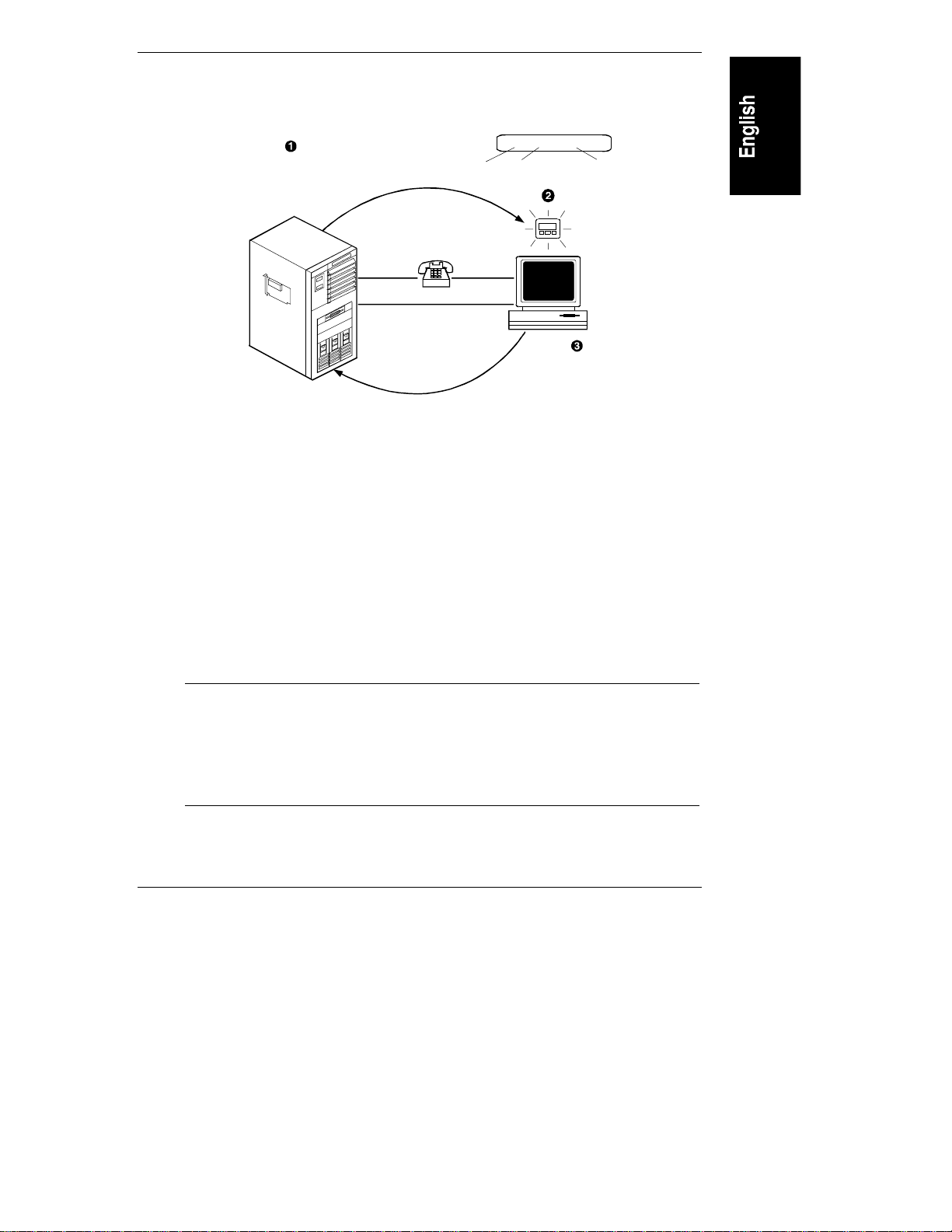
How HP TopTools Remote Control Works
HP TopTools Remote Control operates independent of the server. It has its own
processor chip, a serial and LAN port, and interface. These are completely
separate from the server and the server’s Network Operating System (NOS). The
benefit to network administrators is comprehensive remote server management,
even in the event of a downed server. Thus, HP TopTools Remote Control frees
system administrative staff from direct round-the-clock server monitoring.
When HP TopTools Remote Control detects a problem, it immediately notifies
the assigned administrator by sending a notification message that identifies the
server and the nature of the problem using one or more of the following methods:
• E-mail (server ID and short text message identifying the problem)
• Numeric page (server ID and five-digit event code)
• Alphanumeric page (server ID and short text message identifying the
problem)
Regardless of location, an administrator can log in to the server using a standard
web browser and run HP TopTools Remote Control software to identify and, in
many cases, correct server problems. See Figure 2-1.
6
Page 13
Chapter 2 Introducing TopTools Remote Control
Userreceives an email or a page
(shown below)that identifies the
server andthe event code that
triggeredthe notification.
19010 90021 Memoryerror
Whena notification-enabled
event occurs, HP T opT ools
RemoteControl sends
apage or email to the
configureduser.
PPP
LAN
5-digit
Server ID
5-digitcode
identifies
event
Userconnects to HPT opT ools
Rem o teControl from
aLANor PPPconnected
remote client toobtainmore
informationand rundiagnostics.
0211 TEMPW
T ext description
(ifusingaTAP
pager)
Figure 2-1. HP TopTools Remote Control M anagement Process
Package Contents
Your HP TopTools Remote Control product contains the following:
• An HP TopTools Remote Control PCI card
• A battery pack (including plastic fastening darts)
• An HP NetServer Navigator CD
• An I
NOTE An optional AC/DC adapter for the HP TopTools Remote
2
C/IPMB cable kit
Control card (HP part number D6138A) is available from your
authorized HP dealer. HP recommends use of the adapter
when you want to extend the card’s remote power on feature
beyond the limits of the battery pack’s capability (30 to 60
minutes).
7
Page 14

Chapter 2 Introducing TopTools Remote Control
Documentation
HP TopTools Remote Control includes the following documentation:
• This guide, which describes how to install the HP TopTools Remote
Control and set it up to communicate with the server.
• HP TopTools Remote Control online help, which describes all aspects of
the user interface including how to use HP TopTools Remote Control to
manage your network server.
• pcANYWHERE32 online documentation. The complete pcANYWHERE32
User Guide is in Adobe Acrobat PDF format on the HP NetServer
Navigator CD in the \util\pca32\xx\ subdirecory (where xx rep resent s a
two letter abbreviation for your local language).
• The HP TopTools Remote Control README file located in the \ttrc\us
dir ectory of the HP NetServer Navigator CD, provides up-to-date
information that became available after this guide was printed.
Acronyms
The following acronyms designate hardware and software components that are
associated with HP TopTools Remote Control installation or usage. You will
encounter these acronyms throughout this user guide.
• DHCP: The Dynamic Host Configuration Protocol provides a mechanism
through which computers using TCP/IP can obtain protocol configuration
parameters automatically through the network.
2
• I
C: Inter-Integrated Circuit bus. A multi-master, two-wire, serial bus
used as the basis for the Intelligent Platform Management Bus.
• IPMB: Intelligent Platform Management Bus. Name for the architecture,
protocol, and implementation of the industry-standard server management
bus that interconnects the server’s system board and chassis
instrumentation electronics. TopTools Remote Control connects to the
IPMB via the I
system sensors and the server’s front panel and reset controls.
2
C cable, thus p roviding access to the ser ver’s event log,
• PPP: Point-to-Point Protocol. A standardized network protocol for dial-up
network connectivity.
8
Page 15

Chapter 2 Introducing TopTools Remote Control
• TFTP: Trivial File Transfer Protocol. This file transfer protocol allows
PUT and GET operations with absolute file names and does not require
user authentication. TopTools remote control uses TFTP to implement
firmware upd ates and remote boots.
Who Should Use This Guide
This guide is designed for system administrators and people who are familiar
with installing, managing, and troubleshooting servers on a network. It assumes
that you’r e knowledgeable about using operating systems such as Microsoft
Windows 95 and NT, using web browsers such as Microsoft Internet Expl orer
and Netscape Communicator, and installing software and hardware in PC
systems.
HP TopTools Remote Control Features and
Functions
HP TopTools Remote Control provides a wealth of server management features
that make it a powerful remote management tool. HP TopTools Remote Control
works independently of the server’s state and network operating system. An onboard, web-based user interface is accessed via communications ports (for modem
or LAN) that are functionally independent from the HP NetServer on which the
HP TopTools Remote Control card is installed.
An on-board battery or an optional external AC/DC power adapter keeps HP
TopTools Remote Control functional even if the server loses power.
For security reasons, access privileges are mapped to user groups. In the
following chapters, all features and functions are described from an
administrator’s point of view. However, subsets of the HP TopTools Remote
Control features and functions are also available for use by operators and users.
Remote Control
Remote server console redirection. An administrator at a remote client
(connected to the server via a m odem and or LAN) can view the server cons ol e
screen and take control of the keyboard
server. HP TopTools Remote Control supports chara cter-based server console
screens. Windows NT graphics console redirection is supported using Symantec’s
pcANYWHERE32 software (incl ud ed on the HP NetServer Navigator CD).
Remote access t o ser ver power functions. An administrator at a remote client
has virtual control of the server’s power states. He or she can reset the server with
, performing operations as if seated at the
9
Page 16

Chapter 2 Introducing TopTools Remote Control
a gra ceful shutdown (if th e NetServer SNMP agent software i s i nstalled), a
reboot, or a comp lete p ower cycle. An admi nistrator c an also remote ly power off
the server if, for example, there has been a critical hardware failure. If text
remote contr ol is enabl e d durin g serve r re boot, the actual bootup s c reens can be
viewed at a remote site.
Remote configuration. An administrator at a remote client can reconfigure HP
TopTools Remote Control and change features such as notification actions. An
administrator can also change user and administrator permissions without having
to be at the server.
Management and Security
Remote management security. An administrator can assign access for up to 16
users, providing them with individual login identification, encrypted password
and privileges. User privileges define the right to perform a specific action (for
example, powering down the server). Use management can thus be set up by an
administrator at a remote site without compromising network security. The
TopTools Remote Control login procedure is protected so that the password is not
sent across the LAN.
Dialback option. If a user is using modem communications, the HP TopTools
Remote Control card may be configured for dialback. Dialback authorization
requires the user’s ID. If the ID matches an entry in the user database, HP
TopTools Remote Control initiates an automatic call-back via the external
modem connected to the ca rd.
Server Performance Monitoring
HP TopTools Remote Control monitors I/O performance by gathering statistics
on PCI bus usage. The following server operations and conditions are monitored:
• Bus utilization. The ratio of use to total PCI cycles. This is an indicator of
the server’s I/O load.
• Bus efficiency. The ratio of the amount of data transferred (throughput)
to total PCI data transfer capacity. This is an indicator of how effectively
the s erver’s PCI devices are usi ng th e bu s .
HP TopTools Remote Control monitors the following conditions:
Environment monitoring. HP TopTools Remote Control displays sensor values
for each sensor in the server. These include sensors for voltages, temperatures,
and fan speed.
Logging of server events. HP TopTools Remote Control displays the server’s
System Event Log (SEL) information for viewing by an administrator at a remote
10
Page 17

Chapter 2 Introducing TopTools Remote Control
client. This is the same event log available via TopTools when the server is
online.
Event notification. HP TopTools Remote Control notifies designated users when
an event occurs that has been specified for notification. Using Remote Control
notification, an administrator’s valuable time is freed from constant surveillance
of the server, and server downtime is kept to a minimum. HP TopTools Remote
Control can send notification via email using the Simple Mail Transfer Protocol
(SMTP), numeric pager, or alphanumeric pager using the Telocator
Alphanumeric Protocol (TAP). An administrator can define the notification path
and enable or disable paging for any event group.
TAP paging allows the HP TopTools Remote Control to send meaningful text
notifications to designated pagers. If your mobile phone service provider supports
the TAP protocol, you can use HP TopTools Remote Control to send Short
Message Service (SMS) n oti fications up to 160 characters in length to your
mobile phone.
Diagnostics
Memory diagnostics. If enabled, this function reads continuously through the
complete memory range at a defined maximum performance impact. Single bit
errors are logged and a session count is calculated.
Last screen before Automatic Server Restart (ASR). If the NetSer ver SNMP
agents software is installed, HP TopTools Remote Control automatically captures
a snap shot of the server’s screen (blue scr een on Windows NT servers) up on a n
ASR event, preserving error messages or other screen activity that appeared
before restart. An administrator can view the snapshot from a remote client and
use the screen contents to tr oubl es hoot server problem s .
Other Features
Automatic server shutdown on voltage or temperature emergencies. The HP
TopTools Remote Control card can be configured to automatically shut down
your server if it detects an over-voltage or over-heating condition.
Remote floppy boot of the server. For remote reboot, HP T opTools Re mote
Control allows an administrator to specify a boot floppy image file located on a
TFTP server (see Appendix C for details). The HP NetServer in which the HP
TopTools Remote Control card is installed automatically fetches this boot image
after a reset operation and executes the new boot image. Using this feature, for
example, an administrator can remotely update the HP NetServer’s BIOS, or
remotely run server diagnostics.
11
Page 18

Chapter 2 Introducing TopTools Remote Control
Remotely upgrade firmware. The HP TopTools Remote Control management
program code is stored in Flash ROM on the HP TopTools Remote Control card.
If it is necessary to upgrade the firmware, a newer r evision of the program code
may be downloaded via a TFTP server to the programmable ROM (see Appendix
C for details). When available, new firmware versions can be obtained from the
HP web s ite.
SNMP support. HP TopTools Remote Control includes SNMP support
embedded in firmware on the Remote Control card. SNMP queri es (MIB-II)
provide seamless integration with any SNMP mana g em ent platform including
HP TopTools and HP OpenView. SNMP t raps th a t occur d uring a server hang or
power down may be forwarded to a management console of your choosing. These
management solutions provide in-band (network connected) monitoring of your
servers.
DHCP support. DHCP is based on a client-server paradigm in which the HP
TopTools Remote Control card contacts a DHCP server for configuration
parameters. The DHCP server is typically centrally located and operated by the
network administrator. The HP TopTools Remote Control card can be reliably
and dynamically configured with parameters appropriate to the current network
architecture. These parameters are the IP address, subnet mask and default
gateway.
HP TopTools Remote Control System
Requirements
Minimum Server Requirements
To install and use HP TopTools Remote Control, you will need:
• An HP NetServer system that supports I
slot.
NOTE The HP TopTools Remote Control card is only supported in
HP NetServers that support the I2C/IPMB. Currently, these
includ e systems such a s the HP NetServer LC 3, LH 3 and
LH 4. If you don’t have one of these systems, refer to your HP
NetServer’s system documentation to confirm that it supports
the HP TopTools Remote Control card.
12
2
C/IPMB and has an available PCI
Page 19

Chapter 2 Introducing TopTools Remote Control
• The server must also have been initially set up with a Network Operating
System and the HP NetServer SNMP agent s i nstalled. HP TopTools
Remote Control uses these agents to perform certain functions. If you are
not sur e, refer to the HP NetServer SNMP a g ent installation instructions
available from the Information Assistant program on the HP NetServer
Documentation CD that came with your NetServer.
• An external modem (requir ed only for paging and dia l -up remote access).
A list of recommended modems is included in Appendix B. An updated
(most current) list may be found on the Tested Products List for your
particular HP NetServer. To view this list, refer to Appendix B.
• A dedicated 10Base-T compatible LAN connection (required for email
notification and LAN access) and a unique IP address for the HP
TopTools Remote Control card (either fixed or DHCP).
• For HP NetServers running Windows NT 3.51 or 4.0, full graphics
console redirection to the remote client is available using Symantec’s
pcANYWHERE32 (see Chapt er 6, Setting Up NT Graphics Console
Redirection Using pcANYWHERE32).
Minimu m Remote Client Requ iremen ts
To access HP TopTools Remote Control, you need the following:
• A personal computer with an Intel Pentium processor
• A VGA color display (800 X 600, greater than 256 colors minimum
resolution)
• Micr osoft Windows 95 ( with Ser vice Pack 1), Wind ows 98 , or Windows
NT 4.0 (with service pack 3)
• TCP/IP stack (included with Microsoft Windows software)
LAN C onnect ion Requirements
To access HP TopTools Remote Control via LAN, you need the following:
• LAN connection with 10Mbit support
• Supported Web Browser (see below)
• pcANYWHERE32 Version 8.0 for Windows NT server con sole
redirection (included on HP NetServer Navigator CD)
13
Page 20

Chapter 2 Introducing TopTools Remote Control
Dial-up (PPP) Connect ion Requirements
To access HP TopTools Remote Control via modem, you need:
• A supported modem (refer to Appendix B) and phone line
• MS Windows NT or 95 Dial-up Networking installed. For non-Windows
platforms, suitable PPP software installed.
• A supported Web Browser (see below)
• pcANYWHERE32 Version 8.0 for Windows NT server con sole
redirection (included on HP NetServer Navigator CD)
Supported W eb Br owsers
To access HP TopTools Remote Control’s web-based user interface, one of the
following web browsers must be installed at the remote client:
• Internet Expl orer 4. 01 with Service Pack 1 (version 4.72.3110.8, update
version SP1, as viewed from the "About Internet Explorer" option under
Help) or higher (downloadable from Microsoft’s web site:
www.microsoft.com)
• Netscape Communicator 4.5 (as viewed from the "About Communicator"
option under Help) or higher (downloadable from Netscape’s web site:
www.netscape.com)
14
NOTE Netscape 4.5 does not allow for independently resizing Java
applets i nside HTML frames.
Page 21

3 Hardware Installation and
Configuration
This chapter provides instructions for installing the HP TopTools Remote
Control card in a server and setting up a hardware connection that permits
remote management of the server. (See Chapter 4 for information on setting up
HP TopTools Remote Control management software.) Installation and
configuration of the hardware includes:
• Verifying and, if necessary, updating system BIOS for compatibility with
HP TopTools Remote Control
• Preparing the HP TopTools Remote Control card
• Installing the HP TopTools Remote Control card
• Verifying that the HP TopTools Remote Control card has been installed
correctly
• Running the HP TopTools Remote Control BIOS setup program
15
Page 22

Chapter 3 Hardware Installation and Configuration
Verifying and Updating the Server’ s System BIOS
To verify that the server’s system BIOS is compatible with HP TopTools Remote
Control:
1. Insert the HP NetServer Navigator CD supplied with HP TopTools
Remot e Cont rol i n the NetServer’s CD-RO M dri ve and reboot. Th e
Navigator CD boots and automatically verifies that the system BIOS and
firmware are compatible with HP TopTools Remote Control.
2. If the system BIOS (or associated firmware) is out of date or otherwise
incompatible, update it.
3. Wh en you have finished , remove the HP NetServer Navigator CD and
reboot th e s ystem.
Preparing the HP TopTools Remote Control Card
The HP TopTools Remote Control card can function independently of the server’s
power state (on or off). Power for the card can be supplied through the use of the
included rechargeable on-board battery pack and/or an optional external AC/DC
adapter.
For example, if the server power is not available due to a power failure, HP
TopTools Remote Control switches automatically to an alternate source. The first
priority is to use the external AC/DC adapter, if an AC/DC adapter is not
available, it uses the battery.
NOTE Without an external AC/DC adapter, the battery pack is able
to power the HP TopTools Remote Control card for about one
hour in case of a server power failure. When the server’s
power is on, the battery recharges off the server’s PCI bus.
Mountin g the Batter y Pack
The battery pack must be mounted on the HP TopTools Remote Control card
before the card is installed in the server. Note that the battery’s sides are slotted
so that it can slide onto the pr inted circuit board as shown in Figure 3-1.
16
Page 23

Chapter 3 Hardware Installation and Configuration
CAUTION The HP TopTools Remote Control card is sensitive to static
electricity and can easily be damaged by improper handling.
Use of an antistatic service kit, such as 3M® 8501/8502/8505
or equivalent is recommended.
To mount the battery pack:
1. Place the HP TopTools Remote Control card on a clean non-conductive
surface and disconnect the battery cable from the card.
2. With reference to Figure 3-1, the cooling vents on the battery pack should
be on the same side as the board components. Be sure the battery cable is
situated on the right and can easily reach the battery connector on the
card.
1.Slide battery
onto board
2. Insert darts
fromrear side
of board
Co olingvent s
3. Plug battery
cable into battery
connector.
Figure 3-1. Connecti ng t he Batt er y Pack and Cables
3. Make sure that the battery pack is securely mounted to the card using two
of the supplied plastic darts. These must be pressed in from the back (the
circuit side) of the card. The third dart in the package is a spare.
NOTE In case the battery must be removed (for exchange or
replacement), use a screwdriver or a coin to remove the darts.
17
Page 24
Chapter 3 Hardware Installation and Configuration
4. Plug in the cable leading from the battery pack into the battery connector
on the card (refer to Figure 3-1).
For proper operation make sure that the battery is fully charged after installation
into the server. Charging takes about two hours after the server has been powered
up, or after the optional AC/DC power adapter has been plugged in.
CAUTION The battery pack is already pre-charged. Be careful handling
the battery pack – a short-circuit in the battery cable can
damage the battery pack.
For detailed information about battery operation, replacement, recycling, and
disposal, see Appendix E.
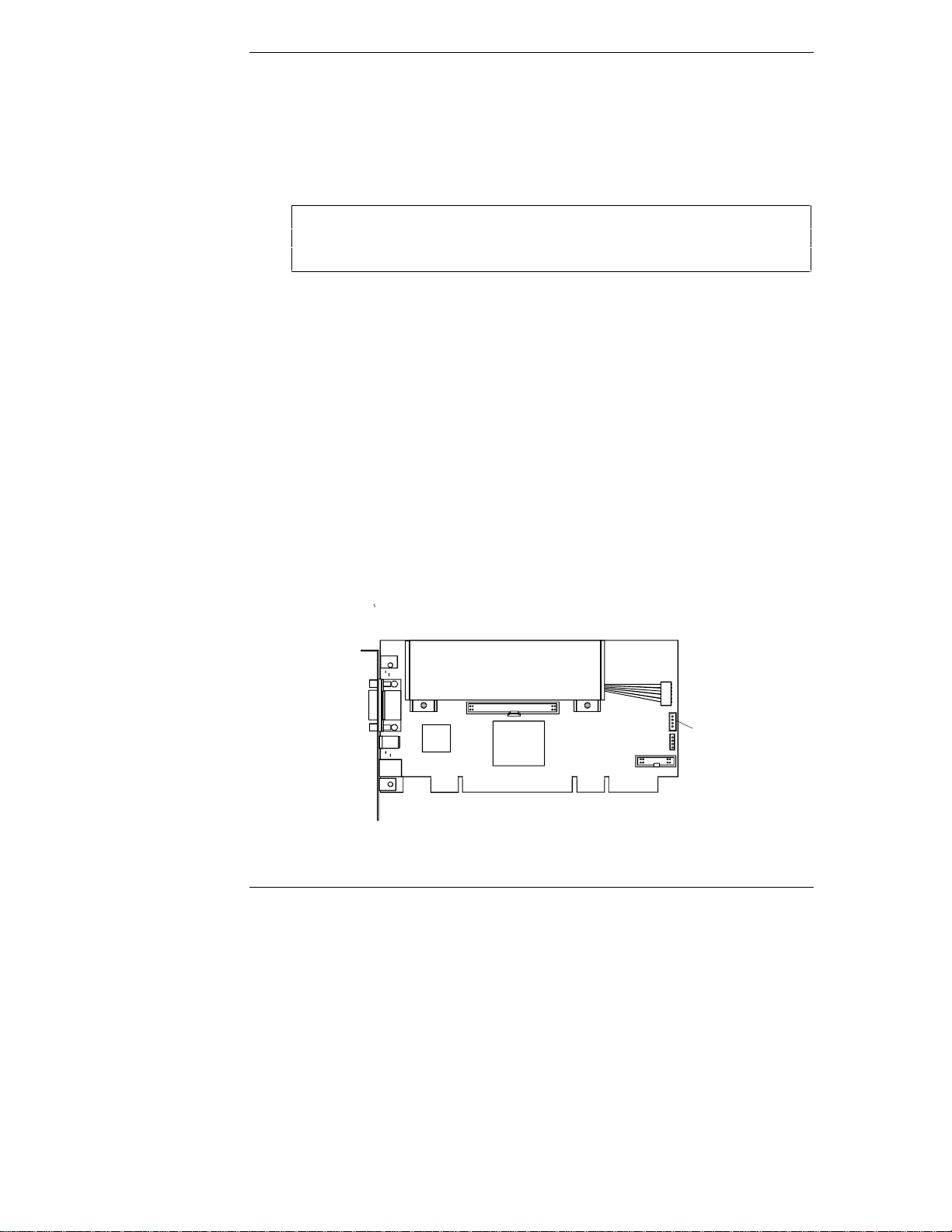
Connecting th e I2C Cable to the Remote Control Card
HP TopTools Remote Control provides an I2C/IPMB interface. This 4-pin
conn ector pr ovid es access to th e I
2
C/IPMB bus on th e ser ver system board . It
allows remote monitoring of all sensors (for example, voltages and temperatures)
built into the system board, as well as access to the System Event Log (SEL) and
control of the front panel power and reset buttons.
Before installing the HP TopTools Remote Control card in the server, you need to
conn ect the I
1. Locate the I
2
C cable t o t he car d . To conn ect the I2C cable:
2
C cable connector on th e HP T op Tools Remote Con trol card.
You'll find it next to and just below the battery pack connector. (Refer to
Figure 3-2.)
2
IC/IPMB
connector
18
Figure 3-2. Locati ng t he I2C/IPMB Connect or
Page 25

Chapter 3 Hardware Installation and Configuration
2. Plug in either en d of the I2C cable (HP Part Number 5183-6569).
2
Note: I Ccable
end connectors
are identical
Figure 3-3: I2C cable
Installing the TopTools Remote Control Card in
the Server
The exact procedure for installing the HP TopTools Remote Control PCI card
depends on your particular server model. For specific information about
installing a PCI card in your server, refer to the user guide supplied with your
server. See Appendix D, "Technical Specifications," for information about the
power requirements for HP TopTools Remote Control.
WARNING Hazardous voltages are present inside the server. Always
disconnect AC power and un pl ug external connecting cables
from the HP NetServer while working inside the unit. Serious
injury may result if this warning is not observed.
Connecting th e I2C Cable to the Ser ver
After you have physically installed the HP TopTools Remote Control card into
your server, you must cable the card t o t he server’s system board. O ne end of the
supplied I
Car d (see previ ou s s ection). Conn ect the other end to the I
the s erver.
2
C/IPM B ca bl e should a lread y be connected to the Remote Control
2
C/IPM B con nector on
19
Page 26
Chapter 3 Hardware Installation and Configuration
NOTE The I2C cable is both color coded and keyed to plug in to the
I2C/IPMB connector only one way. HP does not support
installations of the HP TopTools Remote Control card in
systems that do not include the I
thes e includ e s ystems such a s the HP NetServer LC 3, LH 3
and LH 4. To find out if your server includes an I
2
C/IPMB feature. Currently,
2
C/IPMB
connector, refer to your server documentation.
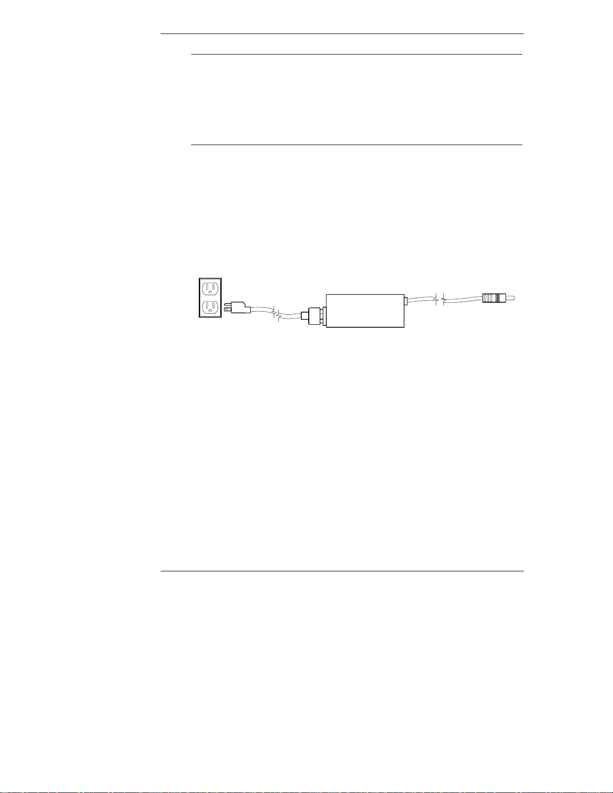
Connecting an Optional AC/DC Adapter
In addition to the battery pack, you may purchase an external AC/DC 5-volt
adapter and use it to supply power to the HP TopTools Remote Control card even
if the server’s power is down. The optional AC/DC adapter (HP part number
D6138A) is available from your authorized HP dealer. HP recommends use of the
adapter when you want to extend the card’s remote power-on feature beyond the
limits of the battery pack’s capability (30 to 60 minutes).
100-240VAC
50-60Hz
Figure 3-4. AC/ DC Adapt e r f or HP TopTools Remote Control car d
5V(±5%)
2.0AMax.
1. Plug the optional AC/DC adapter into an available power receptacle or
Uninterrupt i ble Power Supply (UPS).
2. Plug the power supply cable into the 5-volt DC input on the rear bra cket
of the HP TopTools Remote Control card.
20
Page 27
Chapter 3 Hardware Installation and Configuration
5 volt DC input
Figure 3-5. Pl uggi ng in the Optional AC/ DC Adapter
3. HP recommends that you attach the AC/DC adapter directly to the server
housing using tie wraps to ensure th at t he power supply cable to the card
isn’t accidentally disconnected.
CAUTION Do not power down a server with an installed HP TopTools
Remote Control card if the card’s battery is weak and the card
does not have an AC/DC adapter plugged in. In such a case,
you will not be able to remotely connect to the server until
someone goes to the server site and powers the unit back on.
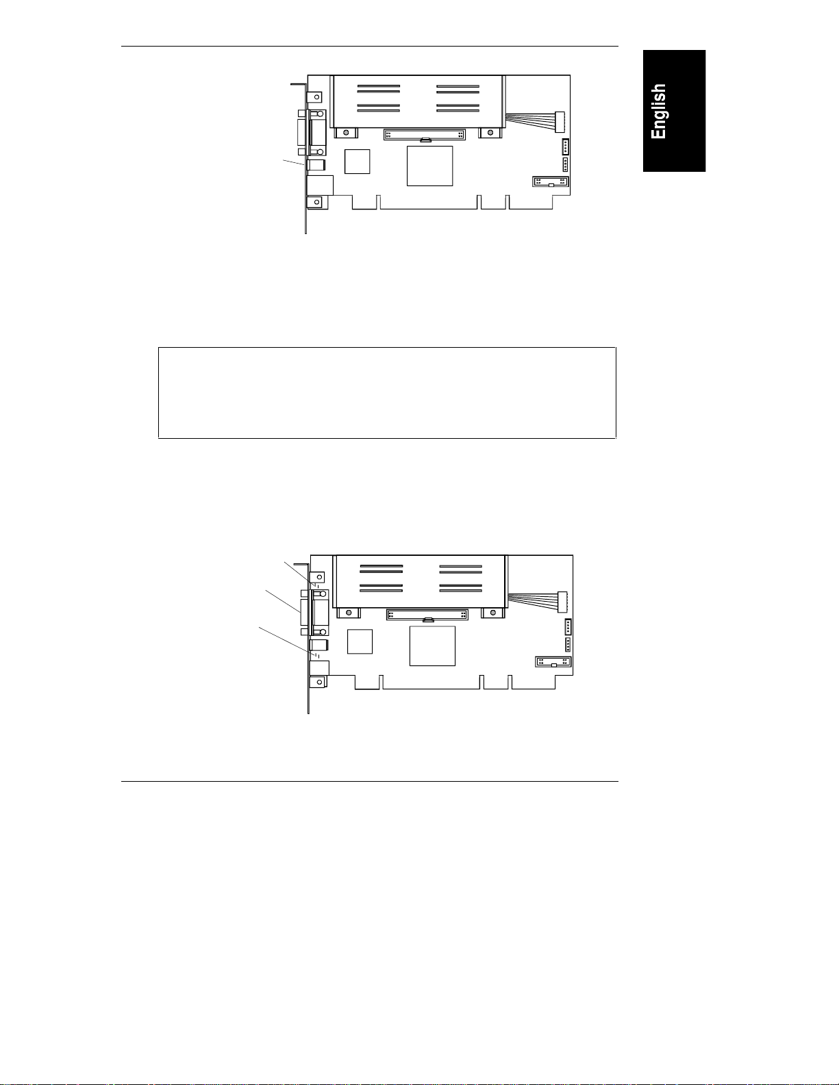
Verifying Card Installation
Each time the HP TopTools Remote Control card is powered up, a built-in
self-test procedure automatically executes.
Diagnostic LEDs
RS-232 port
LAN LEDs
Figure 3-6. HP TopTool s Remote Control PCI Car d LEDs
21
Page 28

Chapter 3 Hardware Installation and Configuration
Self Test Power Up Sequence
During the HP TopTools Remote Control card’s self test, observe the diagnostic
LEDs locat e d just above the card’s RS-232 port (refer to Figure 3-6).
1. The green (heartbeat) LED and the red (error) LED switch on for about 10
seconds.
2. If n o error s are det ected, the green heartbeat LED flash es every 5 seconds,
indicating normal operation. After initial power-up, the red LED should
not be visi ble.
3. If, after power up, the red error LED switches on, a problem with the HP
Remote Control card is indicated. Refer to Appendix F for detailed
information about blinking LED failure codes.
Before you can use HP TopTools Remote Control, an independent
communications link (LAN or modem) must be set up, cabled, and properly
configu red. Proceed to the next chapt er for detailed instructions on how to set up
a remote connection to the HP TopTools Remote Control card.
22
Page 29

4 Setting Up the Remote Connec tion
This chapter describes how to cable and configure the remote communications
link to HP TopTools Remote Control card (LAN or modem). Once
communications have been established, you may control your HP NetServer using
the HP TopTools Remote Control web interface.
NOTE If you have not provided for an independent communications
link to the card (either via a dedicated LAN line or dial-up
modem line), you will be unable to communicate with the HP
TopTools Remote Control card.
Your options for setting up the server for remote connection include one, or both
of the following:
• A connection through the local area network (LAN) via a dedicated line
connected to the HP TopTools Remote Control card’s LAN port
• A connection through an external modem connected to the HP TopTools
Remote Control card’s RS-232 (serial) port
RS-232
connector
10Base-T
10 Mbit LAN
connector
Figure 4-1. Remote Connection Opti ons
23
Page 30

Chapter 4 Setting Up the Remote Connection
Regardless of the type of physical connection joining the TopTools Remote
Control card and remote client, you must initially use the HP TopTools Remote
Control BIOS setup program at the server (described in the next section) to
configure a communications link between the HP TopTools Remote Control card
and a remote client.
Running the HP TopTools Re mote Control BIOS
Setup Program
HP TopTools Remote Control includes its own on-board processor that provides
remote access and server supervision even if the server’s power and operating
system are not functional. Because of the card’s operational independence, the
installation procedure differs from more standard PCI interface cards such as
LAN cards.
Use the card’s BIOS setup program (available at server bootup) to configure the
card for the interface(s) you are currently using or plan to use. For example, if the
HP TopTools Remote Control card is to be accessed via your local area network,
the LAN settings must be defined. If you are planning both local area network
and m odem a ccess, you need to defin e both LAN a nd the PPP settings.
NOTE Once the communications link is initially configured using the
HP TopTools Remote Control BIOS Setup program, you can
change these configuration parameters at your remote client
using the HP TopTools Remote Control web interface
(described in Chapter 5) without rebooting the server.
To configure the HP TopTools Remote Control card:
1. Boot the s e rver .
2. Wait for the monitor to display the message, "HP TopTools Remote
Control card detected, <firmware version> IP Address <xx.xxx.xxx.xxx>"
then press F3 to enter the HP TopTools Remote Control setup routine.
3. Enter the appropriate number to access the required configuration screen.
To exit the configuration and continue with the boot p rocess, press X.
24
Page 31

Chapter 4 Setting Up the Remote Connection
HP TopTools Remote Control for HP NetServers Card Setup
<L> LAN Settings
<P> PPP Settings
<R> Remote Boot Settings
<F> Firmware Update Settings
<X> Exit
Figure 4-2. Main Setup Screen
The displayed value on any of the setting screens is updated as soon as an entered
value is validated.
LAN Configuration
For a remote connection to the TopTools Remote Control card via LAN, the LAN
Settings screen is used to set up the connector on the card. If you are not sure
how to set network parameters, contact your network administrator for the
correct network settings.
NOTE The HP TopTools Remote Control card requires its own
unique IP address (different from the server’s IP address) since
it functions independently of the server on which it is
installed.
Press the desired letter (D, I, N, or G) on the keyboard to chan ge one of your
Local Area Network settings. An entry window pops up that allows the entry of
the new value. Closing this entry window initializes the validation of the new
entry. If it is valid it will be updated on the corresponding setting screen,
otherwise an error message occurs. Press M to return to the Main Setup Screen.
HP TopTools Remote Control for HP NetServers - LAN Settings
<D> Enable DHCP DHCP is DISABLED
<I> Set IP-Address 192.168.10.10
<N> Set Netmask 255.255.255.0
<G> Set Gateway 127.0.0.1
<M> Main Menu
Figure 4-3. Local Area Net work Configuration
25
Page 32

Chapter 4 Setting Up the Remote Connection
If DHCP is enabled, the next time the HP TopTools Remote Control card reboots
it will obtain its network settings (including its IP address) from the DHCP
server. The card will attempt to keep the assigned network settings for as long as
possible so you won’t n eed to go back into the card’s BIOS setup program to view
a new IP address (or view the card’s new address via HP TopTools Device
Manager) every time the card reboots. If, for some re ason, th e IP address on t he
card changes, an event will be generated warning you of the change. You may
configu re th e card to p age you for this event.
NOTE The TopTools Remote Control card always requests the
maximum lease time for network settings so that they do not
change. It will also attempt to renew the lease before the lease
time expires. As long as the card does automatic renewing in
time, it will not lose the leased IP Address. However, if the
card is switched off, and remains off past the lease renewal
date, it will lose its lease on the IP Address and will need to
obtain a new one.
PPP Configuration
For remote connection to the TopTools Remote Control card via a modem, the
Point-to-Point Network configuration must be enabled and defined. This includes
an initialization string for your external modem, a PPP IP address and a PPP
Netmask address. Typically, you leave the PPP IP address an d PPP Netmask at
the factor y defaults si nce your PPP connection does not i nteract with the sit e
network.
26
NOTE The PPP IP ad d ress must be different from the HP TopTools
Remote Control card’s LAN IP address.
HP TopTools Remote Control for HP NetServers - PPP Settings
<P> Enable PPP PPP is DISABLED
<S> Set PPP Initialization String ATL1M1X3E0S0=3
<I> Set PPP IP-Address 192.168.100.10
<N> Set PPP Netmask 255.255.255.0
<M> Main Menu
Figure 4-4. Point-to-Point Configuration
Page 33

Chapter 4 Setting Up the Remote Connection
Remote Boot Configuration
The HP TopTools Remote Control card i s able t o boot the ser ver using a boot
floppy image file located on a TFTP server (see Appendix C for detailed
information about TFTP remote boot setup). This feature can also be configured
at the remote client using the TopTools Remote Control web interface software.
To us e the remot e boot feat ure:
1. Se t Remot e Boot to "on." N ote that once this is set , th e NetServer will
continue to attempt to boot off a remote boot image until you go back into
the HP TopTools Remote Control BIOS setup program and set this option
to "off."
2. De fine the filen ame of t he boot image.
3. Enter the IP Address of the TFTP server where the image file is located.
4. When you are finished running the HP TopTools Remote Control card’s
BIOS Setup program, restart the NetServer and run the NetServer’s BIOS
Setup program (typically, accessed by pressing F2 when prompted during
the boot-up process). Be sure that the floppy drive is listed as a bootable
devic e and is placed fi rst in the boot order.
HP TopTools Remote Control for HP NetServers - Remote Boot Settings
<R> Disable Remote Boot Remote Boot ENABLED
<N> Set Boot Image Filename bootimg.bin
<A> Set IP-Address of Image TFTP Server 127.0.0.1
<M> Main Menu
Figure 4-5. Prepar at i on for Remote Boot
NOTE Instructions for setting up a TFTP server may be found in
Appendix C, or contact your local network administrator for
the correct TFTP server setup and for available boot images. A
TFTP server should typically be located within your company’s
firewall.
Firmware Update C onfigur ation
If a new or backup version of the HP TopTools Remote Control card firmware is
stored on a local TFTP server (see Appendix C for detailed information about
firmware update configuration using TFTP), use the firmware update screen to
27
Page 34

Chapter 4 Setting Up the Remote Connection
download the desired version onto your card. Note that once you select "Start
Firmware Update" the update begins immediately.
HP TopTools Remote Control for HP NetServers - Firmware Update Settings
<S> Start Firmware Update
<F> Set Firmware Image Filename firmimg.bin
<A> Set IP-Address of Firmware TFTP Server 127.0.0.1
<M> Main Menu
Figure 4-6. Prepar at ion for Firmware Updat e
After firmware update is finished you will be prompted to reboot the c ard , so the
new settings can take effect.
NOTE If you don’t see this prompt or the connection to the HP
TopTools Remote Control card is interrupted during the
firmware update, repeat this update before rebooting the card.
Setting Up a LAN Connection
You can communicate with remote clients by connecting to your local 10Base-T
compatible network using the RJ-45 jack located at the rear bracket of the HP
TopTools Remote Control card and an appropriate cable.
The following figure illustrates a LAN connection joining an HP NetServer (with
HP TopTools Remote Control card) and a remote client.
Remote Client
RJ-45
cable
28
Office
LANjack
HPTopTools
Remote Control
cardto10Base-T
or 10/100 Hub
Figure 4-7. Rem ot e Connect i on via the LAN
Page 35

Chapter 4 Setting Up the Remote Connection
To enable remote connection over your local area network, LAN settings must
have been defined in t he card’s BIOS setup program (see previous section).
Remote Client Configuration (LA N)
Your remote client should already be set up and connected to your local area
network. Verify that TCP/IP protocol is set up properly for the client (client’s IP
Address, Subnet Mask, and Gateway) by checking its properties from the
Network program in the Control Panel. Verify your browser’s proxy settings. If
your site uses a proxy server for Internet access, you will need to bypass the proxy
server by entering the IP address of your HP TopTools Remote Control card in
the exceptions list.
When you are rea d y to make your fir s t connection, proceed to Chapter 5.
Setting Up to Use an External Modem
You can communicate with a remote client by connecting an external modem to
the card’s serial communications port. A modem connection at the remote client
is required to complete the data link. The following figure illustrates this type of
connection joining the server and the remote client.
See Appendix B for information on modem support for HP TopTools Remote
Control.
Phone
jack
Modem
cable
Remote
Client PC
Modem
Phone
jack
RJ-11
cable
Modem
Server
Figure 4-8. Remote Connection Through an External Modem
29
Page 36

Chapter 4 Setting Up the Remote Connection
NOTE HP recommends tha t you supply power to your external
modem from an Uninterrupt ible Power Supply (UPS), so that
you can be notified in case of an AC line power failure.
Remote Client Configuration (PPP/Dial-Up Networking)
This section describes using dial-up networking for a Windows NT 4.0 client.
Windows 95 and 98 configuration steps are similar. For other operating systems,
refer to your system documentation for instructions on how to set up a PPP
connection.
In Windows NT 4.0, after running the TopTools Remote Control BIOS setup
program to configure t he card for PPP communication, do the following to set up
the r em ote cli ent for PPP communi cation with the TopTools Remote Control
card:
1. The Dial-Up Networking feature must be installed and a modem must be
configured through the Windows Control Panel|Modems program.
2. If you want to set up dialback with your TopTools Remote Control Card:
◊ From Control Panel|Modems, select on your modem.
◊ Click Properties.
◊ Select the Connection tab.
◊ Click Advanced. Then add the following string in the "extra settings"
field:
x3&c0&d0
The dialback feature cannot function properly if you do not enter this
string in the Extra Settings field as indicated.
3. Configure Dial-Up Networking by double-clicking the "My Computer"
icon and then "Dial-Up Networking."
NOTE If you wish to configure dialback with the HP TopTools
Remote Control card, you need to login to the card first and
set the dial-back number under Configuration|Users.
4. In the Dial-Up Networking window, include phonebook entry and dialin g
information.
30
Page 37

Chapter 4 Setting Up the Remote Connection
Figure 4-9. Example: Configuri ng Di al-Up Networking in Windows NT 4.0
5. Under "More," select "Edit entry and modem properties." Here you can set
up modem configuration using the "Basic" tab.
6. Click the "Server" tab to specify the dial-up server type, network
protocols, and compression. Make sure your settings match the following
figure. (If you have Windows 95, make sure you do not check the "Login
to network" option.)
31
Page 38

Chapter 4 Setting Up the Remote Connection
Figure 4-10. Defi ne t he Dial-Up Server Type
7. Click the "TCP/IP Settings" button (see Figure 4-11). Select the "Server
assigned IP address" option. The client will automatically get an IP
Addr es s from th e HP TopTools Remote C ontrol ca rd. C heck "Speci fy
name server addresses" and make sure all DNS and WINS en try fields are
set to zero (0). Uncheck "Use default gateway on remote network."
Click OK.
32
NOTE The card derives th e ad d ress using t he PPP IP Address of the
card which it increments by "1". If the resulting address is
equal to "0" or "255," it is incr ement ed by "1" again.
Page 39

Chapter 4 Setting Up the Remote Connection
Figure 4-11. Define TCP/IP Settings
8. Click the "Script" tab. To expedite the TopTools Remote Control login
process, use the script provided by HP included on the HP NetServer
Navigator CD in \ttrc\us\ttrc.scp. Copy this script file to your remote
client and enter that path in the script dialog box.
33
Page 40

Chapter 4 Setting Up the Remote Connection
Figure 4-12. Configure Script
If you don’t wish to use the script, select "Pop up a terminal window"
instead.
9. Cl ick the " S ecu rity" ta b a nd select " accept only encrypted a uthentication".
10. You may now dial up to establish the modem connection to the card using
the card’s external modem phone number. Once connected, you will see a
modem connection icon on the task bar of your desktop.
When you are rea d y to make your fir s t connection, proceed to Chapter 5.
34
Page 41

5 Logging In and Using the HP
TopTools Remote Control Web
Interface
After you’ve installed, cabled, and configured the HP TopTools Remote Control
card using the card’s BIOS setup program, you are ready to set options for the
Remote Control card using HP TopTools Remote Control’s management
software.
Using your web browser you can remotely set all card options including:
• Setting up an administrator list (up to 16) for system access and
notification
• Configuring event management operations, including the enabling of
paging and e-mail notification
• Configuring serial communications for external modem
• Config uring LAN access
CAUTION Configuring LAN access during a remote connection is
dangerous. Changing your LAN access settings while logged
on could terminate your connection.
• Viewing a log of server events and PCI utilization
• Viewin g current mea s u remen t sensor s
• Viewing ser ver screen s
• Running diagnostics on the server
• Performing remote firmware or BIOS updates
• Remotely power on, power off, power cycle, or reset the server
35
Page 42

Chapter 5 Logging In and Using the TopTools Remote Control Web Interface
Logging In to HP TopTools Re mote Control
To initiate a connection to HP TopTools Remote Control from the remote client,
connect to HP TopTools Remote Control via LAN or modem connection, as
follows:
1. If you are u sing a m od em ( PPP) at th e remote cli ent (proceed to step 2 if
you are not), make your connection using the Dial-Up Networking
program. Once connected, you will see a modem connection icon on the
task ba r of your desktop, proceed t o step 2.
2. At the remote client, start your web browser software. Make sure that the
proxy settings for your browser have been correctly set. If your site uses a
proxy server, enter the IP address of the TopTools Remote Control card in
the browser’s exceptions list to bypass it.
3. Enter the URL address of the HP TopTools Remote Control card, which
should be one of the foll owing :
◊ If connecting via LAN, enter the card’s IP address (for example:
http://xxx. xxx. xxx. xxx/ ), or a host name, if one has been assigned to
HP TopTools Remote Control in your DNS server (for example:
http://cardname.companyname.com).
36
◊ If connnecting via PPP, enter the card’s PPP IP-address t hat you
entered when you ran the HP TopTools Remote Control BIOS setup
(for example: http://xxx.xxx. xxx. xxx/)
Once you are connected, the TopTools Remote Control Identity page is
displayed in your browser window (see Figure 5-1).
Page 43

Chapter 5 Logging In and Using the TopTools Remote Control Web Interface
Click here for HP TopTools Remote Control Online Help
Figure 5-1. HP TopTools Remote Control Web Interf ace Sof tware
4. Click the Configuration tab. The login prompt is displayed.
5. In the User Name field, enter a valid administrator name. For your first
login, the factory default n a m e i s ADMI N.
6. At the password prompt, enter the password that belongs to the
administrator name. For your first login, the factory default password is
ADMIN.
NOTE The user ID and the access password for HP TopTools Remote
Control software are case sensitive. To avoid a potential
security breach allowing someone to log in using the defaults,
your first task should be to set up an administrator for the
card. Under Configuration|User, create a new user assigned to
the "Administrator" group and assign a new password. Then
delete th e defaul t ADMI N u ser account.
7. Once logged into the HP TopTools Remote Control web interface, create
your user groups and set your communication and notification
preferences. If you have HP TopTools Device Manager, you can perform
37
Page 44

Chapter 5 Logging In and Using the TopTools Remote Control Web Interface
some administration actions on multiple cards at once. See online help for
details (click the "?" button in the upper righ t corner of the browser
window).
Using the HP TopTools R emote Control Web
Interface
You can use HP TopTools Remote Control web interface to remotely manage the
server in which you have installed the HP TopTools Remote Control card. The
following management features are available for setting up and configuring
remote control of the HP NetServer.
NOTE Only one user can be logged on to the HP TopTools Remote
Control card at a time. To log off, using your web browser,
shift to another URL. By default you are automatically logged
off after five minutes of inactivity (you may increase this time
using the TopTools Remote Control web interface).
For detailed information about each tab, click the online help button in the upper
right corner.
• Identity. Description of key information about the HP TopTools Remote
Cont rol car d and the connected server including compu t er na me,
description, location, and IP Address.
• Status. Provides an Event Log and access to environmental data,
including voltage and temperature readings at the server.
• Configuration. This is where you set up information about event
management (how you will be notified of problems), add users, configure
information about the server, and configure information about the card,
includ i ng LAN and PPP a ssi g nments. From here you can al so set up a
remote firmware update of the HP TopTools Remote Control card or you
can set u p th e HP NetServer to boot us ing a remote boot image.
• Diagnostics. Includes a diagnostic test to scan server memory.
• Remote Control. Used to initiate remote control of server functions,
includ ing s e rver c onsole redirection , remote shutdown and server reboot.
To use these options, you must install the included TFTP software. Refer
to Appendix C for details.
38
Page 45

Chapter 5 Logging In and Using the TopTools Remote Control Web Interface
• Support. Provides listings of additional user resources relative to server
configuration and management. Best used when also connected to the
World Wide Web for rea d y access to HP’s web pag es .
• Use with TopTools Device Manager. TopTools Remote Control fully
integrates with the TopTools Device Manager product (version 4.1x an d
above). Access to your TopTool s Remote Control card may be done via
accessing a server page of a server that has the TopTools Remote Control
card installed, or through the Others list under Devices|Device Types.
Group actions on multiple TopTools Remote Control cards may be
performed using TopTools Device Manager by selecting the cards you
want with your mouse and right-clicking. Group actions include adding
and deleting users, changing user passwords, viewing user configurations,
powering on and off the server, and updating card firmware.
Access to the HP TopTools Remote Control management features depend on the
privilege level of the user. For detailed information about user privileges, refer to
HP TopTools Remote Control online help.
39
Page 46

Page 47

6 Setting Up NT Graphics Console
Redirection Using pcA NYWHERE3 2
For NetServer systems r u nnin g Mi crosoft Windows NT 3.51 or 4. 0 , you can
redirect the server’s NT graphics console to a remote PC client to remotely
perform operations as if you were sitting at the server. To do this, you must
install pcANYWHERE32 software. p cANYWHERE32 compon ents must be
installed and configured at both the server and the remote client to use NT
remote control. The figure below show how it works:
At the RemoteClient Using
the user dials into
aModem:
At the Server:
installing pcANYW HER E32
and configuring it for LAN
and/or modem
communications, the
server maybe takenover
by the remote client via a
LAN and/or modem
connection.
after
HPTopT oolsRemote
Control, selects "NTRemote
Control," hangs up and dials
back to the server using
pcANYWHE RE32and takes
full graphicscontrol of the
HP NetServer.
Modem
NetServer
Modem
LAN
Remote
Console
LAN
Figure 6-1. NT Console Redirection to a Rem ot e Cl ient
At the RemoteClient Using
the LAN:
the user launches
pcANYWH ERE32andtakes
full graphics control of the
HP NetServer.
41
Page 48

Chapter 6 Setting Up NT Graphics Console Redirection Using pcANYWHERE32
Installing pcANYWHERE32 on the Server
To enable console redirection (the ability to redirect what’s graphically displayed
on your server) either over the LAN or via modem, you must first install the
pcANYWHERE32 host software, i ncluded with your system, on your HP
NetServer.
NOTE Remember that the HP TopTools Remote Control card
software license authorizes a single administrator for each
copy of software (includi ng Symantec’s pcANYWHERE32).
Console Redirection Over a LAN
If you want console redirection (remote control) of your server over a LAN
(instead of using a modem with pcANYWHERE32), you must have TCP/IP
software installed on your server. TCP/IP is available with the standard Windows
NT product.
Installing pcA NYWHERE 32 Serv er Softwar e
Installing pcANYWHERE32 at the ser ver requires a dministrator privileges in
order to configure the program’s communications features. Your server must be
running either Windows NT 3.51 or 4.0.
To install the pcANYWHERE32 software at your Win d ows NT server :
1. Log in to Windows NT with administrator privileges. You need to be the
system administrator, or have an account that belongs to the administrator
group.
2. Insert the HP NetServer Navigator CD (supplied with HP TopTools
Remote Control) in the CD-ROM drive.
3. If you want to run p cANYWHERE32 via t he modem connected to the HP
TopTools Remote Control card, install the appropriate NT serial driver by
running one of the following NT driver setup programs.
For Windows NT 4.0, the driver is located in:
x
:\ttrc\us\nt40drvr\setup.exe
For Windows NT 3.51, the driver is located in:
x
:\ttrc\us\nt35drvr\setup.exe
where x: is the letter of your CD-ROM drive. Follow the on-screen setup
instructions.
42
Page 49

Chapter 6 Setting Up NT Graphics Console Redirection Using pcANYWHERE32
4. Run the pcANYWHERE32 setup progr am. From t he Windows Start
menu, click "Run" and browse to the setup program’s location:
x
:\util\pca32\us\disk1\setup.exe
where x: is the letter of your CD-ROM drive. Follow the on-screen setup
instructions.
5. When setup is complete, you are prompted to restart. Remove the HP
NetServer Navigator CD and click OK.
Configurin g pcAN YWHE RE32 Ser ver Software
After you have completed pcANYWHERE32 installation at the server, you need
to configure the software to function as a host for graphics console redirection.
Once configured and enabled, the HP NetServer waits on a direct serial
connection via the HP TopTools Remote Control card’s serial port (COM4 by
default).
To configure pcANYWHERE32 on t he server:
1. Run pcANYWHERE32. Eith er double-click the pcANYW HERE32
program icon i n the p cANYWHERE 3 2 p rogram g roup, or access the
program from the Start menu.
2. At the pcANYWHERE32 main screen, click the Be a Host PC action
button.
Menu bar
Action but ton bar
Figure 6-2. pcANYWHERE32 Server-Si de Toolbar
43
Page 50

Chapter 6 Setting Up NT Graphics Console Redirection Using pcANYWHERE32
3. Make a new connection item for your server. Double-click the "Add Be a
Host PC Item".
4. Configure the connection item for LAN or modem use.
◊ LAN connection: Select TCP/IP a s the connection device.
◊ Modem connection: You will be prompted for a Host Name and
conn ection devi ce. Select the COM port (not modem) as signed by the
HP TopTools Remote Control card’s serial driver (see previous
section).
With your selected COM port highlighted, click Details and check the
communications parameters assigned to the port. Configure the port as
shown in Figure 6-3.
44
Figure 6-3. Conf i gur ing the Server-side CO M Port in pcANYWHERE32
NOTE You can configure the pcANYWHERE32 host to wait for both
a modem and LAN connection by checking both a COM port
and TCP/IP in the host icon’s "Properties."
Page 51

Chapter 6 Setting Up NT Graphics Console Redirection Using pcANYWHERE32
5. Click OK then Next and deselect the checkbox to "Automatically launch
after wizard," then click Finish. Your new connection item appears in the
pcANYWHERE32 main window.
6. Right-click your new connection item and click "Properties".
7. From the Properties menu, click the Settings tab and check the "Launch
with Windows" and "Run minimized" checkboxes. Click OK to return to
the main program window.
8. If you want to rename the connection item you just created, right-click the
connection item and click Rename. Type in the new name.
9. Close pcANYWHERE32 an d restart your ser ver . Once restar ted,
pcANYWHERE32 is automatically launched and ready to support a
remote connection.
You can customize your host configuration to allow for more options and greater
security. For example you can create a list of allowed callers, or enable features
such as call-back. Refer to pcANYWHERE32’s on line hel p for more information
on configuration.
Your pcANYWHERE32 server- si d e installation and configuration is complete.
After rest a rting Windows NT, pcANYWHERE32 is automatically launched and
remains ready, in the background, as an NT service. The server is ready to accept
a call from a remote computer runn in g pcANYWHERE32 remote control
software.
Installing pcANYWHERE32 on the Remote Client
After you have installed pcANYWHERE32 host software at t he HP NetServer
hosting the HP TopTools Remote Control card, you need to install the
pcANYWHERE32 remote client software.
NOTE Remember that the software license authorizes the installation
of pcANYWHERE32 on one remote client and one HP
NetServer. If you want to install pcANYWHERE32 on
additional systems, purchase additional licenses from
Symantec.
The instructi ons that follow focus on the use of pcANYWHERE32 with HP
TopTools Remote Control. pcANYWHERE32 supports man y other additional
features that may be useful to you. For details about pcANYWHERE32’s featu res,
refer to the online pcANYWHERE32 Use r Gu i d e .
45
Page 52

Chapter 6 Setting Up NT Graphics Console Redirection Using pcANYWHERE32
Console Redirection Over a LAN
If you want console redirection (remote control) of your server over a LAN
(instead of using a modem with pcANYWHERE32), you must have TCP/IP
software installed on your client. TCP/IP is available with the standard Windows
NT product.
Installing pcA NYWHERE 32 Remote Client Softwar e
pcANYWHERE32 must be already in stalled and configured as a host on your HP
NetServer before you can initiate a call from your remote client. Refer to
"Installing pcANYWHERE32 on the Server" in t his chapt er for installation and
configuration procedures.
Once installed and properly configured, pcANYWHERE32 runs as a startup
service on your server and is therefore always ready and waiting for a call from a
remote client run ning pcANYWHERE32 remote client softwar e.
To install pcANYWHERE32 at a remote client runn i ng eith er Windows 95, NT
3.51, or NT 4.0, run the pcANYWHERE32 setup progr a m. Inser t t he HP
NetServer Navigator CD into the CD-ROM drive and run setup.exe located in
the following directory:
x
:\util\pca32\us\disk1\setup.exe
where x: is the letter of the CD-ROM. Follow the on-screen instructions to
complete installation of pcANYWHERE32 software at t he client.
Once the software is installed, go to the next section and configure
pcANYWHERE32’s remote features to access and g raphi cally redirect your
server’s console to the remote client.
Configuring pcANYWHERE32 Remote Client Software
The first time you start pcANYWHERE32, the Sma rt Setup Wizard helps you
configure your system by prompting you for basic information. Configure the
connection items depending on the type of connection you want to use. If you
wish, you can configure separate LAN and modem connections to the same HP
NetServer.
To configure pcANYWHERE32 a t t he remote client:
1. Run pcANYWHERE32 eit her by double-clicking the pcANYWHERE32
program icon (in the pcANYWHERE32 program group), or by accessing
it from the Start menu.
46
Page 53

Chapter 6 Setting Up NT Graphics Console Redirection Using pcANYWHERE32
2. At the pcANYWHERE32 main screen, click the Remote Control action
button from the action button bar. You will see the Remote Control
connection items displayed.
Figure 6-4. pcANYWHERE32 Rem ot e Control Connection It ems
3. Create a new connection item to access your HP NetServer by doubleclicking the "Add Remote Control Item". An installation Wizard prompts
you for information needed to set up a new connection item.
4. The Wizard first prompts you for the name of a "New Host to Call". Enter
the name of the HP NetServer where you installed the HP TopTools
Remote Control card and click Next.
5. Select a connection device. Configure the connection item depending on
the type of connection you require. Choose either of the following:
◊ LAN connection: If you are setting up a LAN connection item, select
TCP/ I P and proceed to the following LA N s ection.
◊ Modem connection: If you are setting up a modem connection item,
select an installed modem and proceed to the following modem
section.
NOTE For both Windows NT and Windows 95, you must have a
modem already installed to complete the configuration. If the
PC you intend to use as the remote client does not have a
modem installed and recognized by Windows, you must install
one to proceed.
47
Page 54

Chapter 6 Setting Up NT Graphics Console Redirection Using pcANYWHERE32
To complete configuration of the connection item, proceed to the appropriate
section below.
LAN C onnect ion
1. Highlight the TCP/IP option in the list of connection devices and click
"Details".
2. Enter Gateway information if necessary, then click OK.
3. Identify the Host PC’s n am e (or IP Address for the host HP NetServer),
then click "Next". If you leave this field blan k , p cANYWHERE32
provides a list of available server "Hosts" when you run this connection
item. Be sure not to use the HP TopTools Remote Control card’s IP
Address.
4. Uncheck "Automatically begin remote control session upon Wizard
completion", then click Finish.
5. Optional: To automate login to the host HP NetServer, right click the
connection item you just created and click "Properties", then the
"Settings" tab. Fill in the "Login information" section.
NOTE If you intend to acces s the ser ver through the LAN exclusively,
skip the following "Modem C onnection" section and proceed
to "Finishing Your Connection Items".
Modem Conne ction
1. Highlight an in stalled modem from the list of connection devices and
click Details. Microsoft Windows 95 and NT 4.0 present you with a
pre-configured list of Unimodem entries for your selection.
2. Check to be sure that the "Maximum speed" field corresponds to the
capabilities of the installed modem you selected.
3. Enter the phone number of the HP TopTools Remote Control card’s
modem, then click Next.
4. Uncheck "Automatically begin remote control session upon Wizard
completion", then click Finish.
48
Page 55

Chapter 6 Setting Up NT Graphics Console Redirection Using pcANYWHERE32
Customizing Y our Conne ction It ems
If you want to rename a connection item, right-click it, select Rename, and type
in a new name. You can also copy, paste, and reconfigure a connection item to
create an icon for each server you manage.
Installation and configuration of pcANYWHERE32 at the cli ent is now
complet e. Proceed t o t he next section for inst ructi ons on the use of
pcANYWHERE32 to redirect the NT graphics console.
Using NT Graphics Console Redirection
From your remote client, to enable graphics console redirection (the ability to
redirect what’s graphically displayed on your server) either over the LAN or via
modem, follow the directions listed below.
For a LA N conne ction
To initiate NT remote control via the LAN connection, do not go through the
TopTools Remote Control web in t erface. Simply run the pcANYWHERE32
application at your client. Click the Remote Control action button. Then
double-click the connection item you created for the server you want to manage.
Your NetServer’s console is immediately redirected to your client.
For a Modem connec tion
1. From your remote client, connect to server’s HP TopTools Remote Control
card using dial-up networkin g.
2. Once a connection is established, use your web browser to login to HP
TopTools Remote Control and click the Remote Control tab.
3. Click the "NT Remote Control" button. This switches control of the
TopTools Remote Control card serial port to the server. You have 5
minu t es t o esta bli sh a connecti on u si ng pcANYWHERE32 before
TopTools Remote Control resets the serial port.
4. Hang up the dial-up networking connection. Right-click on the dial-up
networking icon on the task bar (shown below) and click "hang up."
49
Page 56

Chapter 6 Setting Up NT Graphics Console Redirection Using pcANYWHERE32
5. Start pcANYWHERE32. Double-click the remote control connection i tem
for the ser ver’s HP TopTools Remote Control card. pcANYWHERE32
conn ects to th e server and begins redi recting th e N T console.
For more information on using Windows NT console redirection, or for details
about pcANYWHERE32 features, refer to the onl i ne pcANYWHERE32 User
Guide.
50
Page 57

7 Troubleshooting
This chapter provides some guidelines for troubleshooting HP TopTools Remote
Control card. Different sections highlight difficulties related to:
• Installation problems
• Paging concerns
• Remote client issues
Problems with Installation
The HP TopTools Remote C ontrol card does not respond.
Make sure that the HP TopTools Remote Control card is securely seated in a PCI
slot.
Ch e ck th e diag nostic LED s locat e d above the RS-232 port on th e back panel of
the card. If the green (heartbeat) light is not alternately flashing, something is
wrong with the card. See Appendix F, "LED Codes," for more information.
Make sure the server’s system BIOS has been updated to the latest release (see
Chapter 3 for details).
I can only vie w two se nsor s built into m y server, but I know that there must be
more.
If the function "Show all Sensors" lists PCI Efficiency and PCI Utilization only,
check that the I
card and the server’s motherboard is installed and that both end connectors are
securely engaged.
2
C cable connecti on between the HP TopTools Remote Control
Paging
I generated a test page from the HP TopTools Remote Contr ol Configur ation pa ge,
but never received it.
Has a pager number and paging string been set up in HP TopTools Remote
Cont rol? Also check to see that the telephone cor d is properly connected to th e
exter nal m od em. Verify that the correct cable is properly connect ed to the card.
51
Page 58

Chapter 7 Troubleshooting
If your pager service generates repetitive tones when it answers, the HP TopTools
Remote Control modem may interpret the tones as a busy signal and attempt to
re-dial. To prevent this, change the X4 command in the modem initialization
string to X0 (blind dialing).
Can I use H P TopTools Remot e Contr ol to page ce llular phone s us ing Short
Message Service (SMS)?
SMS (Short Messa ge Service) enhances paging by providing the ability to send
and receive sh ort messa g es u p to 160 characters over cellular phones. If your
cellular phone service supports the TAP protocol, you can use HP TopTools
Remote Control t o sen d SMS notifications. Here’s how it works: HP TopTools
Remote Control sends a notification to the provider using TAP, and the mobile
service provider transmits the message to the cellular phone using SMS.
A tes t TAP page init iated by my server was never received by my pager.
The following event codes indicate conditions that interfere with successful
paging.
20202: No Connection
Event code 20202 occurs when one of the following conditions is detected:
1. Your terminal is busy and thus was unable to connect.
2. Your modem is not plugged into the phone line.
3. The terminal may be inactive. Paging companies incur occasional
down-time as they make upgrades and repairs to their terminals.
4. You may have select ed the wron g number for your Terminal Access
Number. This number should not be the same as your pager number. After
dialing, you should hear standard handshaking protocols begin upon
connection.
5. Your modem is having trouble connecting at 300 or 1200 baud. Baud rate
difficulties can usually be rectified by entering the correct initialization
string for your modem. Modem initialization strings for modems
supported by HP are listed in Appendix B.
20203 TAP: No ID=Prompt
Event code 20203 occurs when the terminal does not allow the HP TopTools
Remote Control card to log on to the terminal system. The most common cause is
that your modem is unable to connect at 300 Baud. To correct, see 20202 above
(condition number 5).
52
Page 59

Chapter 7 Troubleshooting
20204 TAP: No message go ahead
Event code 20204 occurs when the Termin al Logon is not accept ed . This
indicates that:
1. Your terminal has required more information than HP TopTools Remote
Control is configured to send.
2. Your paging service provider is not completely adhering to the
alphanumeric paging protocols. If this appears to be the case, call HP
Technical Support.
3. It is also possible that you are not dialing the correct modem access
number. Check to see if the number you are dialing responds with typical
modem handshaking protocols. If not, call your pager service provider and
double-check to be sure you are dialing the correct modem access number
(Terminal Number).
20205 TAP: Message not accepted
Event code 20205 occurs when a message is not accepted by the termi nal.
1. Your message ex ceeds the l ength (number of characters per message) of
the service provider’s limits. Make sure that your service provider supports
a message length of 80 characters.
2. Your Pager ID number is invalid. If you use multiple service providers,
make s u re you have selected the correct s ervice pr ovid er for the Pager ID
or PIN number.
3. Your service i s currently not accepting messa g es . Try to sen d your
message later.
4. Call your service provider and ask them to send you a test message. This
helps determine if the problem lies with your service provider, or if you
are using an invalid Pager ID number.
I generated an e-mail test page using HP TopTools Remote C ontrol and never
received it.
Has an e-mail address and a valid IP address of an SMTP server been set up in
the HP TopTools Remote Control? Check with your local network administrator.
53
Page 60

Chapter 7 Troubleshooting
Remote Client
I cannot log into HP TopTools Remote Control f rom t he remote client.
Are you entering th e correct p assword? The login nam e and password are case
sensitive. The factory default login name is ADMIN. Likewise, the factor y
default login password is ADMIN.
I can no longer c omm unicat e with H P TopTools Remote Contr ol from the remote
client.
If DHCP is enabled for the HP TopTools Remote Control card, the IP address on
the card may have changed. Go back into the card’s BIOS setup program to view
the new IP address, or view the card’s new address via HP T op T ool s D evi ce
Manager.
My web browser gives me proxy errors when I try to log into HP TopTools Remote
Control from the remote client.
If your network uses a proxy server for Internet (World Wide Web) access, you
may need to bypass it to communicate with your HP TopTools Remote Control
card. You do this by manually entering the IP address of your HP TopTools
Remote Control card in the "exceptions" list in your browser’s connection
preferences.
While using c onsole r edirection, I clic k "NT Rem ote C ontrol" but do not see any
graphics.
NT gra p hics console redirection is ma naged via pcANYWHERE32. When
connected via modem, clicking "NT Remote Control" from the Remote Control
page simply redirects control of the HP TopTools Remote Control card serial port
to the host server. Once that has been done, you hang up the connection and run
pcANYWHERE32 on the remote client and dial back into the HP TopTools
Remote Control card. If your server is running Microsoft Windows NT, its
console will be redirected to your remote client.
When connected via LAN, you don ’t n eed to use th e HP T opTools Remote
Contr ol i nterface. Just l aunch pC ANYWHERE32 a nd double-click the
connection item you set up for your server.
When conne cte d to HP TopTools Rem ote C ontrol, I a m logged of f aft er several
minutes of ina ctiv ity.
By default, HP TopTools Remote Control automatically terminates a connection
after five minutes of inactivity. This feature prevents a user from monopolizing
54
Page 61

Chapter 7 Troubleshooting
access especially when the connection is forgotten. An administrator may
change the default automatic logout time.
The keys I type from the remote client don’t appear on the server screen.
Type in the keyboard lock password to unlock the keyboard. The keyboard
remains unlocked until the next system reboot. If th e password does not enabl e
the keyboard, try toggling the Numlock key at the server to enable the numeric
keypad.
My power c ontrol func tions a ppear to be disabled.
Power control functions are disabled when the server’s keyboard lock is on. To
turn off keyboard lock, either execute a remote Reset, or type in the keyboard lock
password using Text Remote Control. Verify that the I
2
C cable i s p roperl y
connected both to the HP TopTools Remote Control card and to the HP
NetServer’s system board.
If you are a member of the "User" group, controlling server power functions is
not one of your privileges.
Some of my remote control functions appear to be disabled.
If the server’s power goes down, some HP TopTools Remote Control functions
that r equir e the server to be powered up are also suspended, including console
redirection, PCI Bus Utilization monitoring, and server resets. The battery will
still allow you to connect to the card and perform functions which don’t require
the server to be powered on.
The card does not accept a new connection even if I have closed a previous
connection.
The HP TopTools Remote Control card allows a maximum of 30 HTTP
connections to be opened at the same time. If you are closing an HTTP
connection it may take about two minutes until the socket disappears. During this
time a new connection may be rejected if the total amount of active sockets is
greater than 30.
While using the Ne tscape browser, resizing of the window logs me out .
If the Netscape client browser window displaying the TopTools Remote Control
page is resized or refreshed the remote client will be logged out for security
reasons. Please login again using your login name and password.
55
Page 62

Chapter 7 Troubleshooting
I forgot my pa ss word and c an no longe r log into the card.
If you are the TopTools Remote Control card administrator and have forgotten
your password, there is a special utility on the HP NetServer Navigator CD that
will allow you to reset the TopTools Remote Control user database back to the
factory defaults (Login=ADMIN, Password=ADMIN). Note that doing this will
erase all existing user account information.
To reset the database, go to the server with the TopTools Remote Control card.
Insert the HP NetServer Navigator CD (L.16.00 or above) and reboot the s erver .
Then find and run the Reset TopTools RCC User Database utility (under
NetServer Utilities or Tool b ox from the Navigator Main Menu).
56
Page 63

A Event Codes
The table below describes the event codes that can be listed in the event log and
optionally directed to specified users via e-mail or pager. When the HP TopTools
Remote Control card sends notification about a server event, it includes the
server identifying number and a five-digit code identifying the event. (If you use
email or a TAP pager, you will receive the server nam e and some d es criptive text
as well.)
In the Severity column, an asterisk (*) indicates that the severity rating depends
on particular data for the event. The final column indicates which NOS agents
need to be loaded on the HP NetServer before the particular event is generated.
Refer to the HP NetServer SNMP ag ents documentation (viewable in HP
Information Assista nt on the NetServer Documentation CD) for agent installation
and configuration instructions.
NOTE It’s a good idea to copy appropriate sections of this table and
keep it wi th the pager you use to receive notifications. A
regularly updated list of HP supported event codes is available
via the WWW at http://www.hp.com/go/netserver.
Notification and log messages are limited to a length of 40 characters.
Event
Code Severity Description Agent
System Power
00201 * Vol tage +5V Threshold None
00202 * Vol tage -5V Threshold None
00203 * Vol tage +12V Threshold None
00204 * Vol tage -12V Threshold None
00206 * Vol tage +3. 3V Threshol d None
00207 Warni ng SCSI Termin ator Voltage Limit Exceeded None
00210 * Primary CPU Voltage Threshold None
00211 * Secondary CPU Voltage Threshold None
00800 * Redundant Power Supp ly Removed or Inser ted None
00801 Warni ng Red undant Power Supp ly Aux or DC Power Failure None
00900 Inf ormati onal Redundant Power Supply Un it Red undancy Gained None
57
Page 64

Appendix A Event Codes
Event
Code Severity Description Agent
00901 Warni ng Red undant Power Supp ly Unit Redundan cy Lo st None
00906 Critical Redundant Power Supply Critical # of Power Supply Units None
20100 Inf ormati onal Remote Initiated <Ctrl-Alt-Del> None
20101 Inf ormati onal Remote Initiated Reset None
20102 Inf ormati onal Remote Initiated Power Cyc l e None
20103 Inf ormati onal Remote Initiated Power Down None
20104 Inf ormati onal Remote Initiated Power Up None
20105 Non-recoverable Critical Threshold Power Down None
20106 Warni ng Front Panel Power Off None
20107 Inf ormati onal Auto matic G r acef ul Shutd own None
20108 Inf ormational Grac eful Shutdown Initiated None
Temperature Sensors
00110 * Prim a r y CPU Tempe rature Thr eshold None
00111 * Secondary CPU Temperature Threshold None
00120 * Sys tem Temper ature Thresho ld None
00170 * Pow er Supply Bo ar d Temp erature Threshold None
Fans
00424 * CPU Fan Warning or Failure None
00430 * System Fan Warning or Failur e None
00432 * Sys tem F an 0 or 1 (I/ O area) Warning or Failur e N one
00433 * Sys tem F an 2 or 3 (rear panel) Warning o r Failure None
00434 * Sys tem F an 4 or 5 (rear pair) Warnin g or Fai lure None
00435 * System Fan 6 or 7 ( fron t pair) Warnin g or Failure None
Memory Errors
01200 Inf ormati onal ECC Si ngle -bit Error Correc ted None
01201 Non-recoverable ECC Multi-bit Erro r None
Critical H ardware Errors
01902 Non-rec overable I/O Channel Check None
01904 Warni ng Uncorrectable Bus Er r or None
01905 Warni ng PCI S ystem Error None
01907 Inf ormati onal Correctable Data Er ror None
02502 Warni ng Cache Prot ocol or Parity Error None
System Hang (ASR)
01701 Non-rec overable Server Reset after NOS Han g (ASR) None
58
Page 65

Appendix A Event Codes
Event
Code Severity Description Agent
01703 Non-recoverable OS Watchdog Pow e r Down None
01704 Non-rec overable Server Power Cycled after NOS Hang (ASR) None
01706 Non-rec overable Warning N O S Hang (ASR) None
POST Errors
01520 P O ST Error None
Security
00530 Warni ng Chassis Intrus ion None
20000 Warni ng Illegal Login Threshold None
20001 Inf ormati onal Remote User L ogin None
20002 Inf ormati onal Remote User L ogout None
20003 Informational Aut ologout None
20004 Inf ormati onal Connection Lost None
20005 Inf ormati onal Dialback Failed None
20006 * Configuration Cleared None
System Status
01602 Warni ng Event Log Cleared None
01620 Warni ng Log Area Getting Full None
01801 Inf ormati onal System B oot (POST Complete) None
19900 Inf ormati onal NetS erver Management Controller Restarted None
19901 * NetS erve r Management Controller Sensor Records Cleared None
20901 Inf ormati onal Front Panel Controller Firmware Updated None
20902 Inf ormati onal Prim a ry Hot Swap Controller Firmware Up dated No ne
20903 Inf ormati onal Sec ondary Hot Swap Controller Firmware Updated None
20905 Inf ormati onal NetS erver Management Controller Firmware Updated None
Remote Control
00000,
54321
20206 Warni ng E-mail Notific ation Failed None
20300 Inf ormati onal Mem ory Diagnos tic Started None
20301 Inf ormati onal Mem ory Diagnos tic Completed Successfully None
20302 Inf ormati onal Mem ory Diagnos tic Stopped by User None
20303 * Mem ory Diagnostic Stopped None
20400 Inf ormati onal Remote Control Card Started None
20401 Warni ng Serious E r ror None
20402 Inf ormati onal Firm ware Update None
Informational Test event code None
59
Page 66

Appendix A Event Codes
Event
Code Severity Description Agent
20403 Warni ng Batte r y Low None
20404 Warni ng Batte r y Disconnected None
20405 Warni ng Configuration I nfo. Corrupted ( set t o defaults) None
20406 Inf ormati onal Remote Control Card IP Address C hanged None
Disk Drives and Controllers
00140,
00141
00240,
00241
01300,
01340,
01341
01301,
01340,
01341
01320 Critical Hot-swap Drive Power Fail Hotswap
01321 Inf ormati onal Hot-swap Drive Cage Te mper ature Mo nitor Error Hotswap
01322 Warni ng Hot-swap Drive Cage Te mper ature Warning Hotswap
01323 Critical Hot-swap Drive Cage Temperature Critical Hotswap
01330,
02740,
02741
01331,
02740,
02741
01332,
02840,
02841
01333,
02840,
02841
21001 Warni ng Drive Volume Capacity Minor Threshol d Volcap
21002 Warni ng Drive Volume Capacity Major Threshold Vol cap
21008 Warni ng Drive Volume Capacity Warni ng Threshold Vol cap
21100 Inf ormati onal SCSI Agent SNMP is Down SCSIFLT/
21101 Inf ormati onal SCSI Agent SNMP is Up SCSIFLT/
21107 Warni ng Duplicate Ho st Adapter ID SCSIFLT/
* Hot-swap Drive Cage Temperature Threshold None
Critical System V oltage Failure: Hot-swap Drive Cage o r S CSI
terminator
Warning Hot-swap Drive Removed Hotswap
Information al Hot-swap Drive Inserted Hotswap
Information al Hot-swap Drive Cage SCSI Cabl e Inserted Hotswap
Warning Hot-swap Drive Cage SCSI Cable Removed Hotswap
Information al Hot-swap Drive Cage SCSI Terminator Inserted Hotswap
Warning Hot-swap Drive Cage SCSI Terminator Removed Hotswap
None
SMART
SMART
SMART
60
Page 67

Appendix A Event Codes
Event
Code Severity Description Agent
21108 Inf ormati onal Host Adapter Discov ered SCSIFLT/
21109 Informati onal Host Adapter Chan ged SCSIFLT/
21110 Critical Host Ad apte r F ailed SCSIFLT/
21111 Inf ormati onal Host Adapter Re covered SCSIFLT/
21112 Warni ng Device F a iled SCSIFLT/
21113 Warni ng SCSI D evice Dis covered SCSIFLT/
21114 Warni ng SCSI D evice Recove red SCSIFLT/
21115 Warni ng SCSI D evic e Changed SCSIFLT/
21116 Warni ng SCSI D evice SMART Failure Event SCSIFLT/
21117 Inf ormati onal ASP I Databas e is Cleared SCSIFLT/
21118 Critical ASPI has Crashed SCSIFLT/
21119 Warni ng No Memory Left for ASPI Operati ons SCSIFLT/
21120 Warni ng Unable to Open ASP I File for Wr itin g SCSIFLT/
21121 Warni ng Unable to Open ASP I File SCSIFLT/
21122 Warni ng ASPI Device F ile Do es Not Exist SCSIFLT/
21123 Warni ng ASPI Memory Allocation is Failin g SCSIFLT/
21124 Warning ASP I Unabl e to Read Database File SCSIFLT/
21125 Warni ng ASPI Database is Corrupted SCSIFLT/
21126 Inf ormati onal ASP I Initializing SCSIFLT/
21130 Inf ormati onal SCSIFLT/SMART Agent is Down SCSI FLT/
21131 Inf ormati onal SCSIFLT/SMART Agent is Up SCSIFLT/
SMART
SMART
SMART
SMART
SMART
SMART
SMART
SMART
SMART
SMART
SMART
SMART
SMART
SMART
SMART
SMART
SMART
SMART
SMART
SMART
61
Page 68

Appendix A Event Codes
Event
Code Severity Description Agent
SMART
21138 Inf ormati onal Host Adapter Discov ered SCSIFLT/
21139 Informati onal Host Adapter Chan ged SCSIFLT/
21140 Critical Host Ad apte r F ailed SCSIFLT/
21141 Inf ormati onal Host Adapter Re covered SCSIFLT/
21142 Warni ng SCSI D evice Fail ed SCSIFLT/
21143 Warni ng SCSI D evice Dis covered SCSIFLT/
21144 Warni ng SCSI D evice Recove red SCSIFLT/
21145 Warni ng SCSI D evic e Changed SCSIFLT/
21146 Warni ng SCSI D evice has SMAR T/predictive Fai lure Ev ent SCSIFL T/
21147 S C SI SMART: Internal F ailure SCSIFLT/
21201 Inf ormati onal Disk Array Configuration Update NetRAID
21202 Warning Physical D r ive State Changed NetRAID
21203 Warni ng Logical Dri ve State Chan ged NetRAID
21204 Warni ng Disk Array I nitialize Started NetRAID
21205 Warni ng Disk Array I nitialize Completed NetRAID
21206 Warni ng Disk Array I nitialize Aborted NetRAID
21207 Warni ng Disk Array I nitialize Failed NetRAID
21208 Warni ng Check Consistency Started NetRAID
21209 Warni ng Che ck Consist ency Completed NetRAID
21210 Warni ng Che ck Consist ency Aborted NetRAID
SMART
SMART
SMART
SMART
SMART
SMART
SMART
SMART
SMART
SMART
DAC
DAC
DAC
DAC
DAC
DAC
DAC
DAC
DAC
DAC
62
Page 69

Appendix A Event Codes
Event
Code Severity Description Agent
21211 Warni ng Che ck Consist ency Correcte d NetRAID
21212 Warni ng Che ck Consist ency Failed NetRAID
21213 Warni ng Reconst ructio n Started NetRA ID
21214 Warni ng Reconstructi on Completed NetRAI D
21215 Warni ng Reconstructi on Failed NetRAID
21216 Warni ng Physical D r ive Predictive Failures NetRAID
21217 Warni ng Physical D r ive Fa ilure Pr edic tion Th resh old Ex ceeded NetRAID
21218 Warni ng Physical D r ive Check Conditions NetRAID
21219 Warni ng New Drive Inserted into Array NetRAID
21220 Inf ormational Dis k Array Controller Battery Mis sing NetRAID
21221 Inf ormational Dis k Array Controller Battery Voltage Low NetRAID
21222 Inf ormati onal Disk Array Controller Battery Temperature High NetRAID
21600 Inf ormati onal SNMP is Down SCSIFLT
21605 Warni ng Host Adapter Timeout SCSIFLT
21606 Warni ng Device Timeout SCSIFLT
21608 Inf ormati onal Host Adapter Discov ered SCSIFLT
21609 Informati onal Host Adapter Chan ged SCSIFLT
21610 Critical Host Ad apte r F ailed SCSIFLT
21611 Inf ormati onal Host Adapter Re covered SCSIFLT
21612 Critical SCSI Device F ailed SCSIFLT
21613 Inf ormati onal SCSI D evic e Discove red SCSIFLT
21614 Inf ormati onal SCSI D evic e Rec overed SCSIFL T
21615 Inf ormati onal SCSI D evic e Changed SCSIFLT
21625 Warni ng ASPI Database is Corrupted SCSIFLT
21900 Inf ormati onal A physical device became online FCARRAY
21901 Informational A physical device became a hot spare FCARRAY
DAC
DAC
DAC
DAC
DAC
DAC
DAC
DAC
DAC
DAC
DAC
DAC
63
Page 70

Appendix A Event Codes
Event
Code Severity Description Agent
21902 Critical A physical device reports a hard error FCARRAY
21903 Warning A phys ical device predicted potential failure (PFA/SMART) FCARRAY
21904 Inf ormati onal Auto matic r ebuild started FCARRAY
21905 Informati onal Manual rebuild started FCARRAY
21906 Inf ormati onal Rebuild completed FCARRAY
21907 Inf ormati onal Rebuild canceled FCARR AY
21908 Critical Rebuild error FCARRAY
21909 Critical Rebuild failed due to new physical device FCARRAY
21910 Critical Rebuild failed d ue to logical device failure FCARRAY
21911 Critical A physical device f ailed FCARRAY
21912 Informational A phys ical device was found (Event not to be logged) FCARRAY
21913 Informational A physical device is gone FCARRAY
21914 Informational A physical device is unconfigured FCARRAY
21915 Informati onal Physical device ex pand c a pacity started FCAR RAY
21916 Inf ormati onal Physical device expand capacity finished FCAR RAY
21917 Critical Physical device expand capacity failed FCARRAY
21918 Critical Command to physical device timed out FCARRAY
21919 Critical Phys ical device command aborted FCARRAY
21920 Inf ormati onal Command was retried FCARRAY
21921 Inf ormati onal Parity Error FCAR RAY
21922 Inf ormati onal Soft Error FCAR RAY
21923 Inf ormati onal Miscellaneous erro r FCARRAY
21924 Inf ormati onal Physical D evic e Res et FCARRAY
21925 Inf ormati onal A physical device became an active spare FCARRAY
21926 Informational A physical device became a warm spare FCARRAY
21927 Inf ormational Request Sense data pres ent FCARRAY
21928 Inf ormati onal Consistency check started FCARRA Y
21929 Inf ormati onal Consistency check completed w ith no errors FCAR RAY
21930 Inf ormati onal Consistency canc eled FCARRAY
21931 Critical Consistency check completed w ith an error FCARRAY
21932 Critical Consistency check failed due to logical dev ice FCARRAY
21933 Critical Consistency chec k failed due to physical device failure FCARRAY
21934 Non-recoverable Logical device became of f - lin e FCARRAY
21935 Critical Logical dev i ce became critic al FCARRAY
64
Page 71

Appendix A Event Codes
Event
Code Severity Description Agent
21936 Inf ormati onal Logical device became o n-li ne FCARRAY
21937 Inf ormati onal Auto matic r ebuild started FCARRAY
21938 Informati onal Manual rebuild started FCARRAY
21939 Inf ormati onal Rebuild completed FCARRAY
21940 Inf ormati onal Rebuild canceled FCARR AY
21941 Critical Rebuild error FCARRAY
21942 Critical Rebuild failed due to new physical device FCARRAY
21943 Non-recoverable Rebuil d fail ed due to lo gical devi ce f ailure FCARRAY
21944 Inf ormati onal A lo gical device initializ ation started FCARRAY
21945 Inf ormati onal A lo gical device initialization completed FCARRAY
21946 Inf ormati onal A lo gical device initialization was canceled FCARRAY
21947 Critical A logic al device initialization failed FCARRA Y
21948 Inf ormati onal A lo gical device was found (event not to be logged) FCARRAY
21949 Inf ormati onal A lo gical device is gone FCARRAY
21950 Inf ormati onal Expand capacity started FCARRA Y
21951 Inf ormati onal Expand capacity finished FCARRAY
21952 Critical Expand capacity failed FCARRAY
21953 Warni ng Bad Block was found FCAR RAY
21954 Inf ormati onal A lo gical device size c hange d FCARRAY
21955 Inf ormati onal A lo gical device type changed FCARRAY
21956 Inf ormati onal A bad data block w as found on a logical device FCAR RAY
21957 Inf ormati onal System starte d FCAR RAY
21958 Critical Write Back error FCARRAY
21959 Inf ormati onal State Table is full FCARRAY
21960 Inf ormati onal Cont rolle r is dead FC ARRAY
21961 Inf ormati onal Cont rolle r has reset FCARRAY
21962 Inf ormati onal A Controller was fo und (event not to be logged) FCARRAY
21963 Inf ormati onal A Controller is gone FCARRAY
21964 Inf ormati onal Batte r y Backup Unit found (Eve nt not to be logged) FCARRAY
21965 Warni ng Battery Bac kup Uni t power is low FCARRAY
21966 Inf ormati onal Batte r Backup Unit power is OK FCARRAY
21967 Non-recoverable Controller has been powe red off FCARRAY
21968 Inf ormati onal Cont rolle r has b een powe red on FCARRAY
21969 Inf ormati onal Cont rolle r online FCARRAY
65
Page 72

Appendix A Event Codes
Event
Code Severity Description Agent
21970 Non-recoverable Controller off line FCARR AY
21971 Critical Controller’s partner is gone FCARRAY
21972 Inf ormati onal Batte r y Backup Unit Recondition Start FCARRAY
21973 Inf ormati onal Batte r y Backup Unit Recondition Finished FCARRAY
21974 Inf ormati onal Batte r y Backup Unit Recondition canceled FCARRAY
21975 Inf ormati onal Physical device size table is full FCARRAY
21976 Non-recoverable Storag e cabinet fan Failed FCARRAY
21977 Inf ormati onal Stor age cabinet fan is OK FCARRA Y
21978 Critical Drive Enclosure fan failed FCARRAY
21979 Inf ormati onal Stor age cabinet fan is not pres ent FCARRAY
21980 Non-recoverable Storag e cabinet power supply f a iled FCARRAY
21981 Inf ormati onal Stor age cabinet power sup ply is OK FCAR RAY
21982 Inf ormati onal Stor age cabinet power sup ply is not present FCARRAY
21983 Non-recoverable Storag e cabinet too hot FCARRAY
21984 Critical Storage cabinet is hot FCARRAY
21985 Inf ormati onal Stor age cabinet temperature is OK FCAR RAY
21986 Inf ormati onal Stor age cabinet temperature sensor i s not pres ent FCAR R AY
Network Interface Controllers
21301 Warning NIC Adapter Mism atch NIC
21320 Warning Received errors exceeded relative threshold NIC
21321 Warni ng Trans mit errors exceeded relative threshold NIC
21322 Warni ng Adapter r eset erro rs ex ceeded relative threshold NIC
21323 Warni ng Ali gnment er rors exceeded relative threshold NIC
21324 Warni ng Giant frame error s exceeded relative threshold NIC
21325 Warning Hardw ar e mismatch error s exceeded relative threshold NIC
21326 Warni ng Late collision e rro rs exceeded relative threshold NIC
21327 Warni ng Excessive collision errors exceeded relative threshold NIC
21328 Warni ng Carrier sense errors exceeded relative threshold NIC
21329 Warni ng Deferral errors exceeded relative threshold NIC
21330 Warni ng No ECB errors exceeded relative threshold NIC
21331 Warni ng Rx overflow errors exceeded relative threshold NIC
21332 Warning Utilization c o unt e x ceeded relative threshold NIC
21340 Warning Received errors exceeded threshold NIC
21341 Warni ng Trans mit errors exceeded threshold NIC
66
Page 73

Appendix A Event Codes
Event
Code Severity Description Agent
21342 Warni ng Adapter r eset erro rs ex ceeded absolute threshold NIC
21343 Warni ng Ali gnment er rors exceeded absolute threshold NIC
21344 Warni ng Giant frame error s exceeded absolute threshold NIC
21345 Warning Hardw ar e mismatch error s exceeded absolute threshold NIC
21346 Warni ng Late collision e rro rs exceeded absolute threshold NIC
21347 Warni ng Excessive collision errors exceeded absolute threshold NIC
21348 Warni ng Carrier sense errors exceeded absolute threshold NIC
21349 Warni ng Deferral errors exceeded absolute threshold NIC
21350 Warni ng No ECB errors exceeded absolute threshold NIC
21351 Warni ng Rx overflow errors exceeded absolute threshold NIC
21352 Warning Utilization c o unt e x ceeded absolute threshold NIC
21353 Warni ng Active N IC in Redunda nt group fai led NIC
21354 Warni ng Failed NIC in redundant group b ecame operational NIC
21355 Warni ng Standby NIC in redundant group failed NIC
21356 Critical All NICs in re dundant group failed NIC
21360 Warning Received errors exceeded delta threshold NIC
21361 Warni ng Trans mit errors exceeded delta threshold NIC
21362 Warni ng Adapter r eset erro rs ex ceeded delta threshold NIC
21363 Warni ng Ali gnment er rors exceeded delta threshold NIC
21364 Warni ng Giant frame error s exceeded delta threshold NIC
21365 Warning Hardw ar e mismatch error s exceeded delta threshold NIC
21366 Warni ng Late collision e rro rs exceeded delta threshold NIC
21367 Warni ng Excessive collision errors exceeded delta threshold NIC
21368 Warni ng Carrier sense errors exceeded delta threshold NIC
21369 Warni ng Deferral errors exceeded delta threshold NIC
21370 Warni ng No ECB errors exceeded delta threshold NIC
21371 Warni ng Rx overflow errors exceeded delta threshold NIC
21372 Warning Utilization c o unt e x ceeded delta threshold NIC
Notification (Never Paged)
20201 Inf ormati onal Modem er ror None
20202 Inf ormati onal No Connection None
20203 Inf ormati onal TAP: No ID= Pro mpt None
20204 Inf ormati onal TAP: No Message go ahead None
20205 Inf ormati onal TAP: Message n ot accepted None
67
Page 74

Appendix A Event Codes
Event
Code Severity Description Agent
Other
21401 Warning Tape Read Problems TapeAlert
21402 Warni ng Tape Wr ite Problems TapeAler t
21403 Warning Tape Read/Write Data Error TapeAlert
21404 Warning Tape Faulty Me dia TapeAlert
21405 Warning Tape Read Fault TapeAler t
21406 Warni ng Tape Wr ite Faul t TapeAlert
21407 Warning Tape Worn Out Media TapeAle r t
21408 Warning Tape Substandard Media TapeAlert
21409 Warni ng Tape Wr ite Protec ted TapeAlert
21410 Warning Tape Locked, Ejec t Refused TapeAlert
21411 Warning Tape Media is Cleaning Cartridge TapeAlert
21412 Warni ng Tape U nsupported Media TapeAlert
21413,
21414
21415 Warning Tape Cartridge Mem ory Failed TapeAler t
21416 Warning Tape Cartridge Ejected Dur ing Operation TapeA lert
21417 Warning Tape De tected Read-on ly Media TapeAl ert
21418 Warning Tape has Corrupted Direct ory TapeAlert
21420 Warni ng Tape Drive Ne eds I mmediate Cleaning TapeAlert
21421 Warni ng Tape Drive Ne eds R outine Cleaning TapeAle rt
21422 Warni ng Tape Worn Out Cleaning Cartridge TapeAler t
21423 Warni ng Tape Invalid C leaning Cartr idge TapeAl ert
21429 Warning Tape Requires Preventi ve Maintenance TapeAlert
21430 Warni ng Tape Drive Hardware Fault: Needs Reset TapeAlert
21431 Warni ng Tape Drive Hardware Fault: Needs Power Cycle TapeAlert
21432 Warning Tape Dri ve SCSI Inte rface Fault Tap eAlert
21433 Warning Tape Dri ve Eject Media Request TapeAlert
21434 Warning Tape Dri ve Incorrect Firmware D ownl oad Attempt TapeAlert
21435 Warni ng Tape Device Humidity Specification Exceeded TapeAlert
21436 Warni ng Tape Device Temp. Specifi cation Exceeded TapeAlert
21437 Warni ng Tape Device Voltage Speci ficat ion Exceeded TapeAlert
21438 Warni ng Tape Device Predicte d to Fail: Call Helplin e TapeAlert
21439 Warni ng Tape Device May have Hard ware F ault: Run Diagnostics TapeAlert
21440 Warning Tape A utoload er Com munica tion F ault Tape Alert
Warning Tape Snapped Media TapeAlert
68
Page 75

Appendix A Event Codes
Event
Code Severity Description Agent
21441 Warning Tape A utoload er Stray Tape TapeAlert
21442 Warning Tape A utoload er Mechanism Fault TapeAle rt
21443 Warning Tape A utoload er Door Open TapeAle r t
21444 Warning Tape A utoload er Door Hardwar e Fault: Call Helpline TapeAlert
21445 Warning Tape A utoload er Door Need s Magazine TapeA lert
21446 Warni ng Tape Device Predicte d to Fail: Call Helplin e TapeAlert
21447 Warning Tape A utoload er Door Need s Magazine TapeA lert
21450 Warni ng Library has Communications Fault TapeAlert
21451 Warning Librar y has Change r Mechanism Fault TapeAlert
21452,
21453
21454 Warni ng Library May have Ha rdware Fault: Run Diagnostics TapeAlert
21455 Warni ng Library has Lost I nterface Fault TapeAlert
21456 Warni ng Library Predic ted to Fault: Call Helpline TapeAlert
21457 Warni ng Library Requires Preventive Maintenance TapeAlert
21458 Warni ng Library Humidity Specification Exceeded TapeAlert
21459 Warni ng Library Temperature Spe cifi cation Exceeded TapeAlert
21460 Warni ng Library Voltage Spe cifi cation Exceeded TapeAlert
21461 Warni ng Library Detects Stray Tape in Drive TapeAlert
21462 Warni ng Library has Problems Pic king Car tridg e from Slot TapeAlert
21463 Warni ng Library has Probl ems Placing Cartridge into Slot TapeAlert
21464 Warning Librar y has Problems L oading Cartridge into Drive Tape Alert
21465 Warni ng Library Door is Open TapeAle rt
21466 Warning Librar y has Mechanical F a ult with Mail Slot Tape Alert
21467 Warni ng Library Needs Magazine TapeAlert
21468 Warni ng Library Security has been Compromised TapeAlert
21469 Warni ng Library Security Mode Changed TapeAlert
21470 Warni ng Library Manual ly Turne d Offline TapeAl ert
21471 Warni ng Library Driv e Turned Off line TapeAlert
21472 Warni ng Library has Probl ems R eadin g Barco de Lab els TapeAlert
21473 Warni ng Library Inventory is Inconsi stent TapeAlert
21474 Warni ng Invalid Library Op eratio n Attempted TapeAle r t
21501 Critical APC U P S Co mmunication Lost APC/UPS
21502 Critical APC UP S Overload APC/UPS
21503 Critical APC UP S Self-Test Failed APC/UPS
Warning Library has Hardware Fault: Reset Lib rary TapeAlert
69
Page 76

Appendix A Event Codes
Event
Code Severity Description Agent
21504 Critical APC U P S Discharged Battery APC/UPS
21505 Warni ng APC UPS on Battery APC/UPS
21506 Warning APC UPS Smart-B oost Enabled APC/ UPS
21507 Critical APC U P S Lo w Battery APC/UP S
21508 Inf ormati onal APC UPS Commun ication Est a blished APC/UPS
21509 Inf ormati onal APC UPS A/C Power Restored APC/UPS
21510 Inf ormati onal APC UPS Self-Test Passed APC/UPS
21511 Inf ormati onal APC UPS Return from L ow Battery APC/UPS
21513 Inf ormati onal APC UPS Sleep Mode Enabled APC/UPS
21517 Critical APC U P S Battery Needs Replacement APC/UPS
21518 Critical APC Measure- UPS Contact Fault APC/UPS
21519 Informati onal APC Measure-UPS Contact Nor mal APC/U PS
21520 Critical APC U P S Hardw are F ailure Bypass AP C/UPS
21521 Warni ng APC UPS On Software Bypass APC/UPS
21522 Warning APC UPS On Bypass via Rear Swi tch APC /UPS
21523 Inf ormati onal APC UPS Return from Bypass APC/UPS
21524 Critical APC U P S P o wer Supply Failure Bypass APC/UPS
21525 Critical APC U P S Bas e Fan Failure APC/UPS
21526 Critical APC UP S Battery P ack Com munications Lost APC/UPS
21527 Warni ng APC UPS Battery Pack Commun ications Established APC /UPS
21528 Warni ng APC UPS Run-Tim e Calibration Initiated APC/UPS
70
Page 77

B Recommended Modems
For modem connection to the HP TopTools Remote Control card, an external
modem is required. HP recommends that you use the same model (or at least the
same brand) of modem at the remote client that you use at the server. A list of
recommended modems with their initialization strings for PPP communication
and numeric paging is listed in Table B-1 below.
Table B-1. Recommended Modems and Initialization Strings
Modem Model Initialization String (for PPP and Nume r i c Paging)
Generi c Hayes
Compatible
Diamond SupraExpress
56e SP (K56Flex)
Hayes Optima 33.6 ATQ0V1X4S0=3&K3&C1&Q5&D3S36=7B33
Hayes Accura
56K+FAX(K56Flex)
Motorola
ModemSURFR 56K
MultiTech MT1432L ATQ0&Q1V1X4S0=3&E4&C1$BA0&E1&E13&D3B0
MultiTech MT2834BA ATQ0&Q1V1X4S0=3&E4&C1$BA0&E1&E13&D3B0
MultiTech
MT5600ZDXV
(K56flex)
Microcom Des kPort e
28.8S/14.4S
USR Sportster 56K
Faxmodem(X2)
USR Sportster 33.6
Faxmodem
USR Courier
V.Everything 33.6/28.8
ZyXEL Omni 288S ATQ0V1X4S0=3&H3&C1&B1&K4&D3B0&N0
ATQ0V1X4S0=3&C1&D2
ATQ0V1X4S0=3&K3&C1\N2%C3+MS=V34
ATQ0V1X4S0=3&K3&C1&Q5%C3B0&D3S37=0
ATQ0V1X4S0=3&K3&C1%C2%C3+MS=11
ATQ0V1X4S0=3&K3&C1&Q5\N2%C3&D3B0+MS=11
ATQ0V1X4S0=3\G0&K3&C1&Q5 %C3 &D3B0 +MS=1 1, 1
ATQ0V1X4S0=3&H1&R2&C1&B1&M5&K2&D3B0&N0
ATQ0V1X4S0=3&H1&R2&C1&B1&M5&K2&D3B0&N0
ATQ0&A1V1X4S0=3&H3&R2&I0&C1&B1&M5&K1&D2B0&N0
71
Page 78

Appendix B Recommended Modems
Getting the Latest Recomm ended M odems List
An updated list of recommended modems may be found on the HP NetServer
Tested Products List. To review the Tested Products List, go to either:
• HP NetServer Navigator CD: To access the modem list from the HP
NetServer Navigator CD:
1. Insert the HP NetServer Navigator CD into a client with a CD-ROM
drive.
2. Run Windows Explorer and double-click on the TPL.HLP file located
in the TPL directory.
• HP web site: For the most up-to-date modem list, go to HP’s web site.
Open your browser and enter the following URL:
http://www.hp.com/netserver/support/compatibility/
compatibility.asp
Refer to the "HP NetServer Tested Products Lists."
72
Page 79

C Installing and Using TFTP
Overview: W hat I s TFTP?
TFTP, the Trivial File Transfer Protocol, allows the HP TopTools Remote
Con trol c ard to acces s boot floppy images and new firmware images stored at a
LAN or modem-connected computer. TFTP is built on top of TCP/IP and is
functionally a subset of FTP. As its name indicates, this protocol is used to
transfer data between a "TFTP server" and either the HP TopTools Remote
Control or some other device that acts as the "TFTP client."
NOTE TFTP and the HP TopTools Remote Control card depend on
the TCP/IP protocol. If you are able to view the HP TopTools
Remote Control user interface on your remote computer, this
protocol is already functioning correctly. If not, modification
of eit her your brows er or networking environme nt may be
required.
HP TopTools Remote Control uses the TFTP service to:
• Access boot floppy images that allow administrators to help diagnose HP
NetServer problems and update the server BIOS.
• Update HP TopTools Remote Control firmware.
TFTP file transfer consists of client-side and server-side components. Because the
HP TopTools Remote Control card has the client TFTP service built into its
firmware, you can use TFTP to transfer either firmware images or boot images
from either a local or a remote computer running a TFTP server program, see
Figure C-1.
73
Page 80

Appendix C Installing and Using TFTP
HP NetServer
Local systemwith
TFTP Server Software
and firmware or floppy
image
LAN
with TopTools
Remote Control
card
OR
Remote Client with TFTP
Server Softwa re andfirmware
or floppy image (firmware
update of TopT ools Remote
Control Card NOT allowed
using PPP)
LAN
or
PPP (Modem)
Figure C-1. Usi ng TFTP t o Remotely Supply Updates and Boot Images
TFTP server side software for Windows 95 and Wi ndows NT is supplied on t he
HP NetServer Navigator CD as the file:
\ttrc\us\tftpserv.exe
The s erver software is desi g ned onl y to serve files to a TFTP cli ent, not to r eceive
them. The software provides additional security by allowing the client to retrieve
files only from a directory which is designated on the command line when
starting the server.
NOTE Contact your local network administrator for the correct TFTP
server setup and for available boot images.
For any of the following operations you may also use another available TFTP
server such as the TFTP server daemon normally supplied with UNIX
workstations and servers.
74
Page 81

Appendix C Installing and Using TFTP
TFTP Re q u ir e m e n ts
To use the TFTP service with HP TopTools Remote Control, you must have:
• TFTP client software. The client software is already built into the
firmware of the HP TopTools Remote Control card.
• TFTP server software (tftpserv.exe). To run tftp serv you need one of
the following operating systems:
◊ Microsoft W indows N T 4.0
◊ Mi c rosoft W indows N T 3.51
◊ Mi c rosoft W indows 95 or 98
TFTP server software requires TCP/IP availability on the computer on which it
will run.
Starting the TFTP Server
To start the supplied TFTP server, you must execute the program "tftpserv.exe"
on the server in a DOS window or using the Run… command from the Windows
Start menu. Usage is as follows:
tftpserv.exe [
root
]
where [ root] in dicates the base directory from which a client can retrieve files. If
you do not specify [root], the directory containing the tftpserv.exe file is used as
the ba s e d irectory.
A TFTP client can request files within the base directory or its subdirectories but
does not have access to lower directories. The server software enables the base
directory to act only as a file source, not as a file destination.
Updating HP TopTools Remote Con trol Fir mwar e
If a new or backup version of the HP TopTools Remote Control card firmware is
stored on the TFTP server, you can download the update to your HP TopTools
Remote Control card. This must be done over the LAN. Firmware update of the
TopTools Remote Control card is not supported using a PPP connection.
To update the HP TopTools Remote Control firmware, you must have a firmware
image file stored under the base directory used by the TFTP server.
There are two different methods you can use to update HP TopTools Remote
Control firmware:
• Update Option 1 requires hands-on access to the NetServer.
• Update Option 2 uses the HP TopTools Remote Control web interface.
75
Page 82

Appendix C Installing and Using TFTP
To configure the Remote Control card for firmware updates, use one the
following procedures:
Update Option 1
1. Shut down and reboot the HP NetSer ve r contain ing the HP TopTools
Remote Control card.
2. Enter the BIOS setup interface by pressing F3 when prompted duri ng
HP NetServer boot.
3. Select "<F> Firmware Update Settings", and enter the IP address of the
TFTP server and the filename of the firmware image. The filename you
enter should include a relative path from the base directory.
4. Ensure the TFTP server is running.
5. Select "<S> Start Firmware Update".
Update Option 2
This option may be performed on a single card or, if you have TopTools Device
Manager, multiple cards at once. Instructions for a single card are listed here. To
perform this action on multiple cards, refer to the TopTools Remote Control
online help.
1. From the HP TopTools Remote Control software interface, click the
Configuration tab.
2. Then click the Card Info button.
3. In the Card Maintenance section, fill in the IP address of the TFTP server
and the filename of the firmware. The filename you enter should include a
relative path from the base directory.
4. Ensure the TFTP server is running.
5. To start the firmware update, click Update.
For example, if the TFTP server used \tftp\public as its root and the
firmware image file is named
\tftp\public\hp\fw\ttrc\us\ttrc_rom.bin
you would enter the file name as:
hp\fw\ttrc\us\ttrc_rom.bin
An update can also be performed using a firmware image file and TFTP server at
a remote client (see Figure C-1).
76
Page 83

Appendix C Installing and Using TFTP
NOTE HP recommends that you do not update the HP TopTools
Remote Control card firmware if the link between the TFTP
server and the HP NetServer is a dial-up network connection.
A disconnection during an update can leave the HP TopTools
Remote Control card partially updated and you would need to
repea t the u p d ate before proceeding .
A firmware update takes approximately one minute over a 10Base-T LAN
connection. After the update has completed, the HP TopTools Remote Control
will be reset in order to start the new firmware.
Using the H P TopTools Remote Contr ol Rem ote Boot Featur e
You can us e the HP TopTools Remote Control to r emotel y boot the HP N e tSer ve r
in which you have installed the HP TopTools Remote Control card. The card
boots the HP Ne tSer ve r using a boot floppy image located on a TFTP server.
Starting an HP N e tServe r from a remote boot image requires that you have
already created an alternate bootable floppy image file and that this image is
available in the base directory used by the TFTP server. After the HP TopTools
Remot e Cont rol process es a re mote reboot, the feature is disa bled automatically
so that the next boot will be a local boot.
You use the HP Copydisk utility to create a floppy image file. The 1.44MB file
created contains a sector-by-sector copy of the floppy plus a 32-byte copydisk
header; you can also use generic floppy image files (no header) created with other
utilities. The image file (usually with the extension .DSK), when a ccessed via
TFTP, is interpreted by the HP NetServer with the HP TopTools Remote Control
card as if it were a local floppy disk image. Thus, the HP NetServer boots us ing
this image as if it were accessing a bootable disk stored in floppy drive A.
The ability to create a floppy boot image opens up powerful remote
administration possibilities. A system administrator can create boot floppy
images to:
• update the server BIOS
• change and/or upda t e software drivers
• boot your var ious diagnostic utilities
• boot virus-checkin g software
77
Page 84

Appendix C Installing and Using TFTP
NOTE Check the HP NetServer’s BIOS Setup program (typically,
acces sed by pre s sin g F2 whe n prompted during the boot
process) to ensure that the floppy drive is positioned at the top
of the lis t of bootable devi c e s in t he boot order.
Creating a Floppy Boot Ima ge
Before you c an create a boot image, you must get a copy of the HP utility
"copydisk.exe".
NOTE Do not confuse HP’s copydisk.exe with the DOS utility
diskcopy. e xe su pp l ied with Micr osoft MS-DOS operating
systems.
Copydisk can be found on the HP NetServer Navigator CD in the dir ectory
\ttrc\us
In the following procedure, you format a floppy disk to include system (boot)
capability and load the software (drivers, applications) that you want run during
the boot process. Finally when you have provided all necessary software
components to the disk, you copy an image of the floppy to your TFTP server
using copydisk.exe.
To creat e a floppy boot image:
1. Insert a 1.44MB floppy disk in drive A and format it. This could be at a
Windows 95 or 98 client, but to ensure that the diskette has enough room
for all the files, use a system with MS-DOS 6.x. At a DOS prompt: ent er
the command
format /s a:
The /s parameter instructs DOS to inclu d e the system on the disk , making
the disk bootable.
2. Copy all drivers and software (e.g. BIOS update) to the floppy disk drive.
Create an appropriate autoexec.bat file on the floppy to run the desired
program(s).
3. Using the HP Copydisk utility, create a floppy boot image file in the root
directory of your TFTP server. Use the following syntax:
copydisk a:
78
x:\path\filename.dsk
Page 85

Appendix C Installing and Using TFTP
where a: is the source diskette and
x:\path\filename
is the
destination drive, path and filename with a .dsk extension for your image
file. An image file is created and transferred to the designated directory.
Initiating a Re mote Boot U sing a Floppy Boot Im age
There are t wo ways to boot t he HP NetSer ver using a remote boot image:
• Remot e Boot Option 1 requires "hands-on" access at the HP NetServer.
• Remot e Boot Option 2 uses the HP TopTools Remote Control web
interface.
Remote Boot Option 1
To us e Remote Boot Opti on 1 m e thod, you mus t have pr operl y configured HP
TopTools Remote Control. Refer to "Running the HP TopTools Remote Control
BIOS Setup Program" in Chapter 4.
In Re mote Boot O ption 1, you start from the user interface stored in the HP
TopTools Remote Control ROM based setup options.
1. Boot the HP N e tSer ver.
2. When the HP TopTools Remote Control banner appears, press F3 when
prompted. You are presented with a menu of configurable options.
3. Enable the Remot e Boot feat ure in the BIOS setu p. Be su re it is "on."
4. Ente r the fil e nam e of the boot image.
5. Supply the IP Address of the TFTP server. That is, i dent i fy the IP Address
of the ser ver where the r e mote boot image is located.
6. Reboot. Du ring the HP NetServer r eboot, a messa ge in dicates that the
server is attempting to start from the designated boot image.
Remote Boot Option 2
The secon d remote boot method re quires you to log onto the HP TopTools
Remot e Cont rol web i nterface in order to set up a remot e boot.
To set up a remote boot, using the HP Top Tools Remote Control use r interface:
1. From the HP TopTools Remote Control user interface, select the Remote
Control tab.
2. Under Server Control, select one of the following HP NetServer start-up
options:
79
Page 86

Appendix C Installing and Using TFTP
◊ Power on (if the s erver is off)
◊ Power cycle
◊ Reset
Once you have selected an action that would bring the HP NetServer back
online , you can fur ther sele c t Remote Boot feat ures.
3. Se lect Remote Boot . Th is en ables HP TopTools Remote Con trol to retri e ve
a floppy disk image from the designated remote computer.
4. Ente r the IP Addre ss of the TFT P server and the fil e nam e of the boot
image. The filename you specify should be a relative path from the root
directory.
5. Press "Start Power/Reset Option" to initiate the remote boot.
As an example, if the TFTP server used \tftp\public as its root and the file of
interest is named:
\tftp\public\hp\boot\ttrc\us\dos.dsk
you would enter the file name as:
hp\boot\ttrc\us\dos.dsk
Example s of R emot e Boot Using a Floppy Boot Image
Using the HP utility copydisk.exe, you can remotely administrate numerous
alternate boot routines and a utomate a range of diagnostic procedures for your
HP NetServers.
The following examples demonstrate how an administrator would set up and use
floppy boot images in a typical network:
• Example 1: A remote server BIOS update
• Example 2: A remote boot of HP Diagnosti c Assi sta n t
• Exam p l e 3: A remote DOS file tr ansfer
In these examples a remote client functions as the TFTP server (refer to Figure
C-1). As you review these examples, keep in min d t hat for each scenario, the task
could be accomplished in some other fashion. For example, the TFTP server
could be located elsewhere on the intranet.
80
Page 87

Appendix C Installing and Using TFTP
Example 1: A remote server BIOS update
In this example, the system administrator wants to update the BIOS of a remote
HP NetServer. The administrator first obtains the latest BIOS from the HP web
site and downloads it to a local hard disk. The administrator then runs the self
extracting BIOS update file and copies the biosxyz.dsk file to the tftpserv base
directory. The ad ministrator then uses TopTools Re mote Control to remote boot
the biosxyz.dsk BIOS update disk.
To rem ot ely update t he server BIOS, the administrat or would pr oceed as follows:
1. Obtain up-to-date server BIOS. Go to HP’s web site
(www. hp.com /go/netserver) a nd download the appropriate BIOS upgrade
from the HP NetServer Service and Support page.
2. Ru n the biosxyz.exe s e lf-extra c tin g file to extract th e biosxyz.dsk boot
floppy image file. Copy the biosxyz.dsk file to your TFTP base directory.
3. Run tftpserv.exe. TFTP waits for a request for an image file from the
TopTools Remote Control card.
4. Run the HP TopTools Remote Control web interface. Click the Remote
Con trol tab. S e lect t he Reset and Remote boot option s .
5. In the TFTP IP Address field, type the IP address of your client ma ch i ne.
In the TFTP File Name field, type: biosxyz.dsk.
6. Click "Start Power/Reset Option". The server restarts and TFTP loads the
image file onto the HP TopTools Remote Control card where it is then
supplied to the HP NetServe r as a boot image. The BIOS update executes
automatically. Use Text Remote Control to view the progress of the
update.
Example 2: A remote boot of HP Diagnostic Assistant
In thi s example, th e s ystem administra tor wa nts to boot to HP ’s Diagnostic
Assistant. To do so the adm inistrator obtains a copy of the Diagnostic Assistant
disk from the HP NetServer Navigator CD Diskette Librar y, uses Copydisk to
create a floppy image file, and uses TopTools Remote Control to remote boot the
Diagn osti c Assi st ant disk image.
To remote ly boot Diagnos tic Assist ant, t he administrator would p roceed as
follows:
1. Insert the HP NetServer Navigator CD at the remote Windows client. The
Diskette Library program will auto-start.
81
Page 88

Appendix C Installing and Using TFTP
2. Select HP Diagn ostic Assistant a nd follow the inst ructions to cr ea t e t he
floppy in drive A.
3. Using the Copydisk progra m, create a floppy boot image in the base
directory of your TFTP server. Use the following syntax:
copydisk a: x:\
where a: is the source diskette and
path
\diagasst.dsk
x:\path
is the destination TFTP
base dire c tory on your hard drive .
4. Run tftpserv.exe. TFTP waits for a request for an image file from the
TopTools Remote Control card.
5. Run the HP TopTools Remote Control web interface. Click the Remote
Con trol tab. S e lect t he Reset and Remote boot option s .
6. In the TFTP IP Address field, type the IP address of your client ma ch i ne.
In the TFTP File Name field, type: diagasst.dsk.
7. Click "Start Power/Reset Option". The server restarts and TFTP loads the
image file onto the HP TopTools Remote Control card where it is then
supplied to the HP NetServe r as a boot image. The HP NetServer boots
Diagn osti c Assi st ant.
Example 3: A remote DOS file transfer to update a NetWare driver
In this example, the system administrator at a remote client running Windows 95
wan ts to reboot a remote HP NetServer ru nning N ove ll NetWare in order to l oad
a new SCSI device driver (the old one is believed to be faulty). To do so, the
administrator obtains the latest copy of the driver from HP (AIC7870.dsk) and
copies it to a formatted DOS boot disk, use s c opydisk to create a floppy image
file , and uses TopTools Remote Con trol to remote boot the disk which copie s the
new driver to the DOS par tition. Finally, the administrator uses Text Remote
Console to edit the NetWare startup.ncf file to point to the new driver.
To remote ly reboot and c opy the new driver :
1. Insert a 1.44MB floppy disk in drive A and create a bootable diskette.
This could be at a Windows 95 or 98 client, but to ensure that the diskette
has enough room for all the files, use a system with MS-DOS 6.x. At a
DOS prompt, enter t he command:
format a:/s
The /s parameter instructs DOS to inclu d e the system on the disk , making
the disk bootable.
82
Page 89

Appendix C Installing and Using TFTP
2. Obtain the new driver (in this case AIC7870.dsk). Go to HP’s NetServer
web site (www.hp. c o m/g o /ne tserver) a nd download the appropriate driver
from the HP’s NetServer Service and Support page.
3. Copy the driver file to the formatted floppy in drive A. Copy the DOS
editor to the floppy (in Windows 95, this file is located in:
\windows\command\edit.com).
4. Create an autoexec.bat file on the floppy that includes the following
command lines:
mkdir c:\temp
copy aic7870.dsk c:\temp
edit c:\nw411\startup.ncf
When finished the floppy in a: would include the following files:
command.com
autoexec.bat
aic7870.dsk
edit.com
5. Use the Copydisk progra m to create a flopp y boot image in the base
directory of the TFTP server using the following syntax:
copydisk a:
path
\doscopy.dsk
where path is the TFTP base directory on your hard drive.
6. Run tftpserv.exe. TFTP waits for a request for an image file from the
TopTools Remote Control card.
7. Run the HP TopTools Remote Control web interface. Click the Remote
Con trol tab. S e lect t he Reset and Remote boot option s .
8. In the TFTP IP Address field, type the IP address of your client ma ch i ne.
In the TFTP File Name field, type: doscopy.dsk.
9. Click "Start Power/Reset Option". The server restarts and TFTP loads the
image file onto the HP TopTools Remote Control card where it is then
supplied to the HP NetServe r as a boot image. The HP NetServer boots the
DOS disk an d executes t he autoexec.bat file. It creates a "c:\temp"
dir ectory, copies t he new driver there, and br ings u p the NetWa re
startup.ncf file in the DOS edit or . The administrator uses Text Remote
Console to modify the path to the SCSI driver:
LOAD c:\temp\aic7870.dsk SLOT=10001
The administrator saves the file, exits the editor and runs server.exe to
start the NetWare server.
83
Page 90

Page 91

D Technical Specifications
This appendix provides specifications for the HP TopTools Remote Control PCI
card.
Feature Description
On-Board Features
Physical
Characteristics
Environmental
Conditions
Power
Consumption
Battery
32-bit PCI Bus Master board (occupies a single slot)
with 64 bit form factor
External 9-pin RS-232 connector
External RJ45 for 10Base-T, 10Mbit LAN connector
Rear panel connector for AC/DC adapter
2
I
C/IPMB interface connector
4 MB Static RAM memory
2 MB of Flash ROM memory (firmware is customer-
upgradeable)
Short PCI card
Operating temperature: 5-35 degrees C ambient
Non-operating temperature: -40 degrees to 65 degrees C
Operating humidity: 20% to 80%
Non-operating humidity: 95% non condensing
Operating altitude: 3,046 m
Non-operating altitude: 12,200 m
2 A at +5 V (10 W maximum)
250 mA at +12 V
Custom NiMH rechargeable 4-cell battery
Operating Temperature: 15-35 degrees C ambient*
4.8V, 1100 mAh
Provides up to one hour of standby usage
85
Page 92

Appendix D Technical Specifications
Feature Description
Optiona l AC/DC
Power Adapter
Input voltage: 100 - 240 V AC, 50/60 Hz
Output voltage: 5V ± 5 %
Output current: 2.0 A max.
Operating temperature: 0 degrees to 40 degrees C
Certification: CSA, C22.2 No 950-95, EN 60950, CE
* For optimal battery lifetime, the temperature inside the server should be maintained
below 40 degrees C an d should never exceed 50 degr ees C.
86
Page 93

E Battery Operation
The HP TopTools Remote Control card includes a rechargeable Nickel
Metal-Hydride (NiMH) battery pack that ensures a supply of power to the card
components.
This battery pack contains four cells and is rated at 4.8V at 1100mAH. In case of
a loss of AC power to the server, or a power supply failure, the battery continues
to power the HP TopTools Remote Control for up to one hour. The battery pack,
which is attached to the card with two plastic darts, is designed for easy removal
and repla cement by th e cu stomer.
NOTE HP TopTools Remote Control can continue to perform its
functions with a non-operating battery as long as power is
being supplied to the server or power is being applied by the
optional external AC/DC adapter.
Safety
To reduce the possibility of an electric shock from the local area network, plug
the computer into an AC outlet before connecting to the network. Likewise,
disconnect the network before unplugging t he computer from the AC power
outlet.
Shuttin g Down the Car d to Conserv e Battery Power
In the event that the server must be turned off for an extended period of time and
no external AC/DC adapter is connected, the HP TopTools Remote Control card
should also be shut down. This prevents battery pack discharge while the server
is not in service.
The HP TopTools Remote Control card automatically powers on when AC power
is applied to the server.
Charging
To ensure battery power, the HP TopTools Remote Control card provides two
sources for battery charging. The on-board battery is charged:
• Through the host server’s PCI bus when the host server is powered on, or
• When the card’s optional external AC/DC adapter is connected.
87
Page 94

Appendix E Battery Operation
The HP TopTools Remote Control card also provides the following alternate
charging modes:
• Fast charge. If the card determines that the battery has been depleted, it
begins a fast charge.
• Trickle charge. When the battery is fully charged, the card switches to a
trickle-charge mode of operation.
When power is first applied to the card, the battery is always initially fast
charged. (This is true even if the battery is already fully charged.) After a few
minutes, if the card’s on-board circuitry determines that the battery’s cells are
fully charged, HP TopTools Remote Control automatically switches to
trickle-charge mode.
Battery In itialization
If the server’s power is interrupted, HP TopTools Remote Control automatically
switches to battery operation. HP TopTools Remote Control logs the event and
generates an alert (if so configured). In addition, some HP TopTools Remote
Control functions that require the server to be powered up are also suspended,
including console redirection, PCI Bus Utilization monitoring, and server resets.
If a remote connection is active when power is interrupted, the connection will be
maintained. The HP TopTools Remote Control card will continue to function for
at least one hour on battery power.
NOTE If you are using an external modem with HP TopTools Remote
Control, the modem won’t have access to battery power. To
guarantee power to an external modem, use a modem that is
attached to an Uninterr uptible Power Supply (UPS).
Life Expectancy
The life expectancy of the battery pack varies depending on temperature extremes
and number of charg ing cycles experien ced by the cells. A nominal life
expectancy is over two years. If the card provides less than half an hour of
operation while operating on battery power, it may be time to replace the battery
pack.
88
Page 95

Appendix E Battery Operation
Replacement
To replace the HP TopTools Remote Control battery pack (Part No. 5183-6570)
contact your HP Sales and Service office. In the U.S. call (800) 227-8164. To
order a replacement battery pack from Hewlett-Packard, refer to its Part Number.
Battery Disposal
Nickel Metal-Hydride batteries should be disposed of in a responsible fashion
according to the laws in the country where the card is used.
CAUTION Do not crush, puncture, or incinerate the battery. Do not short
the battery’s external contacts.
89
Page 96

Page 97

F LED Codes
A failure on the HP TopTools Remote Control card is indicated by a flashing
signal pattern displayed by the red diagnostic LED visible above the RS-232 port
(refer to Figure F-1). The other set of LEDs located next to the LAN port indicate
LAN connection activity.
NOTE In the event that more than one error is affecting card
operation, the HP TopTools Remote Control reports only the
first failure discovered.
Diagnostic
LEDs
LAN LEDs
LAN Connector
Figure F-1. HP TopTool s Remote Control LED
NOTE The LEDs mounted on the HP TopTools Remote Control card
are unusually small micro devices that, until activated, appear
as little white dashes on the circuit board.
Each failure is stored as a four-digit code. This allows each code up to 10
"sub-codes" that can be interpreted by the diagnostic utility.
91
Page 98

Appendix F LED Codes
For example, a 2-1-1-2 error (DRAM Error) would appear as:
flash-flash, pause, flash, pause, flash, pause, flash-flash, pause
The failure pattern repeats indefinitely.
Failure C odes
The table below lists the error or report codes, which are flashed by the HP
TopTools Remote Control card’s red diagnostic LED. A flashing red LED always
indicates a problem with the card’s operation.
To determine a Suggested Action, note the first three digits of the error and refer
to the Report Code in the following table. The fourth digit is represented by an
"X" because the number is irrelevant to the analysis.
Table F-1. Fail ur es and Suggest ed Act ions
Report Code
Red LED blink pattern)
(
Failure Reason Suggested
Action
LED on continuously ASIC CPU Subsystem Error See action 1
1111 FLASH-ROM Err or See action 2
211X DRAM Error See action 3
311X LAN Interface Error See action 1
411X RS-232 Interface Error See action 1
511X PCI Inter face Err or See action 1
611X ICMB Error See action 1
The "X" in the report code represents a possible number between 1 and 9 and is
not significant.
Suggested A c tions
The following r emedies refer to the Suggested Actions listed in the last column of
Table F-1 above.
Action 1: First verify the fault. Disconnect the AC/DC adapter from the
card and cycle power at the server to restart HP TopTools Remote Control.
If the same error is reported again, call your local support center.
92
Page 99

Appendix F LED Codes
Action 2: The card firmware may be corrupted and require updating.
You may either use the firmware image that came with the card on the HP
NetServer Navigator CD, or you may download the latest firmware update
image from the HP NetServer BBS or web site (see Technical Support in
Appendix H). This image should be copied to your TFTP server (to use
the TFTP software, refer to Appendix C). If you are unable to complete
this procedure, call your local support center.
Action 3: Call your support center. If you need to call your local support
center, make sure that you have HP TopTools Remote Control product
information on hand including serial and version number. Also be sure to
note the relevant LED code and description.
93
Page 100

 Loading...