

Page 1

hp Integrity cx2600
Installation Guide
Regulatory Model Number: RSVLA-0303-DC
Version 3.0
Manufacturing Part Number: AB216-90001
March 2004
U.S.A.
© Copyright 2004 Hewlett-Packard Development Company, L.P..
Page 2

Legal Notices
Copyright Notices. © Copyright 2004 Hewlett-Packard Development Company, L.P.
The information contained herein is subject to change without notice. The only warranties for HP products
and services are set forth in the express warranty statements accompanying such products and services.
Nothing herein should be construed as constituting an additional warranty. HP shall not be liable for
technical or editorial errors or omissions contained herein.
Adobe and Acrobat are trademarks of Adobe Systems Incorporated. HP-UX Release 10.20 and later and
HP-UX Release 11.00 and later (in both 32 and 64-bit configurations) on all HP 9000 computers are Open
Group UNIX 95 branded products. Intel and Itanium are trademarks or registered trademarks of Intel
Corporation or its subsidiaries in the United States and other countries. Linux is a registered trademark of
Linus Torvalds. UNIX is a registered trademark of The Open Group. Windows is a registered trademark of
Microsoft Corporation.
Printed in the U.S.A.
Reproduction, adaptation, or translation of this document without prior written permission is prohibited,
except as allowed under the copyright laws.
Related Documents. The HP Server Documentation CD-ROM has been provided with your server. It
contains a complete documentation set for the server, including localized versions of key documents. Included
on the CD-ROM are the Site Preparation and Operations and Maintenance guides, which contain in-depth
troubleshooting, installation, and repair information.
The CD will autorun when you insert it into a Windows® workstation, or, point your browser at the index.htm
file located under the Start directory of the CD. All users, including UNIX®/Linux, can access a complete
manual set by viewing the directory manuals. The manuals are in Adobe® Acrobat® Reader (pdf) format.
IMPORTANT The latest versions of these documents, and any updates to these documents, are posted under
the appropriate server at http://docs.hp.com.
Where to Get Help. For online access to technical support information, self-solve tools, online assistance,
community forums of IT experts, broad multivendor knowledge base, and monitoring and diagnostic tools, go
to http://www.hp.com/support.
2
Page 3

1. About This Document
What’s in This Document . . . . . . . . . . . . . . . . . . . . . . . . . . . . . . . . . . . . . . . . . . . . . . . . . . . . . . . . . . . . . . 7
Typographical Conventions . . . . . . . . . . . . . . . . . . . . . . . . . . . . . . . . . . . . . . . . . . . . . . . . . . . . . . . . . . . 7
Related Documents . . . . . . . . . . . . . . . . . . . . . . . . . . . . . . . . . . . . . . . . . . . . . . . . . . . . . . . . . . . . . . . . . . . 8
HP Encourages Your Comments . . . . . . . . . . . . . . . . . . . . . . . . . . . . . . . . . . . . . . . . . . . . . . . . . . . . . . . . . 8
Where to Get Help . . . . . . . . . . . . . . . . . . . . . . . . . . . . . . . . . . . . . . . . . . . . . . . . . . . . . . . . . . . . . . . . . . . . 8
Information to Collect Before You Contact Support . . . . . . . . . . . . . . . . . . . . . . . . . . . . . . . . . . . . . . . . 8
2. Server Overview and Unpacking
Server Overview . . . . . . . . . . . . . . . . . . . . . . . . . . . . . . . . . . . . . . . . . . . . . . . . . . . . . . . . . . . . . . . . . . . . . 11
Unpacking the Server . . . . . . . . . . . . . . . . . . . . . . . . . . . . . . . . . . . . . . . . . . . . . . . . . . . . . . . . . . . . . . . . 13
Unpacking the Server . . . . . . . . . . . . . . . . . . . . . . . . . . . . . . . . . . . . . . . . . . . . . . . . . . . . . . . . . . . . . . . 13
Removing the HP Server from the Shipping Container . . . . . . . . . . . . . . . . . . . . . . . . . . . . . . . . . . . . 13
Installing the HP Server into a Rack. . . . . . . . . . . . . . . . . . . . . . . . . . . . . . . . . . . . . . . . . . . . . . . . . . . 13
3. Installing Additional Components
Safety Information . . . . . . . . . . . . . . . . . . . . . . . . . . . . . . . . . . . . . . . . . . . . . . . . . . . . . . . . . . . . . . . . . . . 15
Service Tools Required. . . . . . . . . . . . . . . . . . . . . . . . . . . . . . . . . . . . . . . . . . . . . . . . . . . . . . . . . . . . . . . . 15
Accessing a Rack Mounted Server . . . . . . . . . . . . . . . . . . . . . . . . . . . . . . . . . . . . . . . . . . . . . . . . . . . . . . 15
Installing Components When the Server is in a Rack . . . . . . . . . . . . . . . . . . . . . . . . . . . . . . . . . . . . . 16
Remove the Server from a Rack. . . . . . . . . . . . . . . . . . . . . . . . . . . . . . . . . . . . . . . . . . . . . . . . . . . . . . . 16
Install the Server into a Rack . . . . . . . . . . . . . . . . . . . . . . . . . . . . . . . . . . . . . . . . . . . . . . . . . . . . . . . . 17
Installing Disk Drives . . . . . . . . . . . . . . . . . . . . . . . . . . . . . . . . . . . . . . . . . . . . . . . . . . . . . . . . . . . . . . . . 18
Removing Hot-Plug Disk Drives . . . . . . . . . . . . . . . . . . . . . . . . . . . . . . . . . . . . . . . . . . . . . . . . . . . . . . 18
Installing Hot-Plug Disk Drives . . . . . . . . . . . . . . . . . . . . . . . . . . . . . . . . . . . . . . . . . . . . . . . . . . . . . . 19
Hot-Swap Power Supply Units . . . . . . . . . . . . . . . . . . . . . . . . . . . . . . . . . . . . . . . . . . . . . . . . . . . . . . . . . 20
Removing and Replacing a Hot-Swap Power Supply . . . . . . . . . . . . . . . . . . . . . . . . . . . . . . . . . . . . . . 21
Front Grill and Top Cover . . . . . . . . . . . . . . . . . . . . . . . . . . . . . . . . . . . . . . . . . . . . . . . . . . . . . . . . . . . . . 23
Removing the Front Grill . . . . . . . . . . . . . . . . . . . . . . . . . . . . . . . . . . . . . . . . . . . . . . . . . . . . . . . . . . . . 24
Replacing the Front Grill . . . . . . . . . . . . . . . . . . . . . . . . . . . . . . . . . . . . . . . . . . . . . . . . . . . . . . . . . . . . 24
Removing the Top Cover. . . . . . . . . . . . . . . . . . . . . . . . . . . . . . . . . . . . . . . . . . . . . . . . . . . . . . . . . . . . . 25
Replacing the Top Cover. . . . . . . . . . . . . . . . . . . . . . . . . . . . . . . . . . . . . . . . . . . . . . . . . . . . . . . . . . . . . 26
Hot-Swap Chassis Fan Units. . . . . . . . . . . . . . . . . . . . . . . . . . . . . . . . . . . . . . . . . . . . . . . . . . . . . . . . . . . 27
Removing and Replacing a Front Panel Hot-Swap Fan . . . . . . . . . . . . . . . . . . . . . . . . . . . . . . . . . . . . 28
Removing and Replacing a Rear Panel Hot-Swap Fan. . . . . . . . . . . . . . . . . . . . . . . . . . . . . . . . . . . . . 29
PCI Card Installation . . . . . . . . . . . . . . . . . . . . . . . . . . . . . . . . . . . . . . . . . . . . . . . . . . . . . . . . . . . . . . . . 31
Removing the PCI Card Cage Assembly . . . . . . . . . . . . . . . . . . . . . . . . . . . . . . . . . . . . . . . . . . . . . . . . 31
Removing a PCI Card . . . . . . . . . . . . . . . . . . . . . . . . . . . . . . . . . . . . . . . . . . . . . . . . . . . . . . . . . . . . . . . 32
Installing a PCI Card . . . . . . . . . . . . . . . . . . . . . . . . . . . . . . . . . . . . . . . . . . . . . . . . . . . . . . . . . . . . . . . 33
Installing the PCI Card Cage Assembly . . . . . . . . . . . . . . . . . . . . . . . . . . . . . . . . . . . . . . . . . . . . . . . . 34
Installing Processors and Memory . . . . . . . . . . . . . . . . . . . . . . . . . . . . . . . . . . . . . . . . . . . . . . . . . . . . . . 36
Removing a Processor . . . . . . . . . . . . . . . . . . . . . . . . . . . . . . . . . . . . . . . . . . . . . . . . . . . . . . . . . . . . . . . 36
Installing a Processor . . . . . . . . . . . . . . . . . . . . . . . . . . . . . . . . . . . . . . . . . . . . . . . . . . . . . . . . . . . . . . . 40
Installing Memory . . . . . . . . . . . . . . . . . . . . . . . . . . . . . . . . . . . . . . . . . . . . . . . . . . . . . . . . . . . . . . . . . 42
Contents
4. Troubleshooting
3
Page 4

Contents
Introduction . . . . . . . . . . . . . . . . . . . . . . . . . . . . . . . . . . . . . . . . . . . . . . . . . . . . . . . . . . . . . . . . . . . . . . . . 47
Troubleshooting Methodology . . . . . . . . . . . . . . . . . . . . . . . . . . . . . . . . . . . . . . . . . . . . . . . . . . . . . . . . . . 47
Using the Front Panel Power Button. . . . . . . . . . . . . . . . . . . . . . . . . . . . . . . . . . . . . . . . . . . . . . . . . . . 48
If the Server Will Not Power Up . . . . . . . . . . . . . . . . . . . . . . . . . . . . . . . . . . . . . . . . . . . . . . . . . . . . . . 48
If EFI Is Not Available . . . . . . . . . . . . . . . . . . . . . . . . . . . . . . . . . . . . . . . . . . . . . . . . . . . . . . . . . . . . . . 49
If the Operating System Will Not Boot . . . . . . . . . . . . . . . . . . . . . . . . . . . . . . . . . . . . . . . . . . . . . . . . . 49
If the Operating System Will Boot. . . . . . . . . . . . . . . . . . . . . . . . . . . . . . . . . . . . . . . . . . . . . . . . . . . . . 49
If Intermittent Server Problems Occur . . . . . . . . . . . . . . . . . . . . . . . . . . . . . . . . . . . . . . . . . . . . . . . . . 49
If DVD Problems Occur . . . . . . . . . . . . . . . . . . . . . . . . . . . . . . . . . . . . . . . . . . . . . . . . . . . . . . . . . . . . . 50
If Hard Drive Problems Occur . . . . . . . . . . . . . . . . . . . . . . . . . . . . . . . . . . . . . . . . . . . . . . . . . . . . . . . . 50
If Console Problems Occur . . . . . . . . . . . . . . . . . . . . . . . . . . . . . . . . . . . . . . . . . . . . . . . . . . . . . . . . . . . 50
Troubleshooting Using Beep Codes (System e-buzzer) . . . . . . . . . . . . . . . . . . . . . . . . . . . . . . . . . . . . . . 50
Troubleshooting Using LED Indicators . . . . . . . . . . . . . . . . . . . . . . . . . . . . . . . . . . . . . . . . . . . . . . . . . . 51
Front Panel LEDs . . . . . . . . . . . . . . . . . . . . . . . . . . . . . . . . . . . . . . . . . . . . . . . . . . . . . . . . . . . . . . . . . . 52
Rear Panel LEDs. . . . . . . . . . . . . . . . . . . . . . . . . . . . . . . . . . . . . . . . . . . . . . . . . . . . . . . . . . . . . . . . . . . 57
Error Messages and Event Logs . . . . . . . . . . . . . . . . . . . . . . . . . . . . . . . . . . . . . . . . . . . . . . . . . . . . . . . . 58
EFI Error and Warning Messages . . . . . . . . . . . . . . . . . . . . . . . . . . . . . . . . . . . . . . . . . . . . . . . . . . . . . 59
Event Logs. . . . . . . . . . . . . . . . . . . . . . . . . . . . . . . . . . . . . . . . . . . . . . . . . . . . . . . . . . . . . . . . . . . . . . . . 62
Management Processor (MP) Event Logs . . . . . . . . . . . . . . . . . . . . . . . . . . . . . . . . . . . . . . . . . . . . . . . 62
Troubleshooting Using Offline Support Tools . . . . . . . . . . . . . . . . . . . . . . . . . . . . . . . . . . . . . . . . . . . . . 63
Offline Diagnostic Environment (ODE). . . . . . . . . . . . . . . . . . . . . . . . . . . . . . . . . . . . . . . . . . . . . . . . . 63
E-Diag Tools . . . . . . . . . . . . . . . . . . . . . . . . . . . . . . . . . . . . . . . . . . . . . . . . . . . . . . . . . . . . . . . . . . . . . . 64
Other Event Logs and General Diagnostic Tools . . . . . . . . . . . . . . . . . . . . . . . . . . . . . . . . . . . . . . . . . 64
Hypothetical Troubleshooting Scenario. . . . . . . . . . . . . . . . . . . . . . . . . . . . . . . . . . . . . . . . . . . . . . . . . 65
5. Cable Connections
Input Power . . . . . . . . . . . . . . . . . . . . . . . . . . . . . . . . . . . . . . . . . . . . . . . . . . . . . . . . . . . . . . . . . . . . . . . . 67
Wire Selection and Terminal Lugs for Connection of DC Power. . . . . . . . . . . . . . . . . . . . . . . . . . . . . . . 68
Core I/O Connections . . . . . . . . . . . . . . . . . . . . . . . . . . . . . . . . . . . . . . . . . . . . . . . . . . . . . . . . . . . . . . . . . 69
Management Processor (MP) . . . . . . . . . . . . . . . . . . . . . . . . . . . . . . . . . . . . . . . . . . . . . . . . . . . . . . . . . 70
Booting the Server . . . . . . . . . . . . . . . . . . . . . . . . . . . . . . . . . . . . . . . . . . . . . . . . . . . . . . . . . . . . . . . . . . . 76
Index . . . . . . . . . . . . . . . . . . . . . . . . . . . . . . . . . . . . . . . . . . . . . . . . . . . . . . . . . . . . . . . . . . . . . . . 77
4
Page 5

Figures
Figure 2-1. hp Integrity cx2600 Server. . . . . . . . . . . . . . . . . . . . . . . . . . . . . . . . . . . . . . . . . . . . . . . . 11
Figure 2-2. hp Integrity cx2600 Server (front view). . . . . . . . . . . . . . . . . . . . . . . . . . . . . . . . . . . . . . 12
Figure 2-3. hp Integrity cx2600 Server (rear view) . . . . . . . . . . . . . . . . . . . . . . . . . . . . . . . . . . . . . . 12
Figure 3-1. Chassis Ground Lug . . . . . . . . . . . . . . . . . . . . . . . . . . . . . . . . . . . . . . . . . . . . . . . . . . . . . 17
Figure 3-2. Front View of the hp Integrity cx2600 Server. . . . . . . . . . . . . . . . . . . . . . . . . . . . . . . . . 18
Figure 3-3. Disk Drives in Server . . . . . . . . . . . . . . . . . . . . . . . . . . . . . . . . . . . . . . . . . . . . . . . . . . . . 19
Figure 3-4. Hot-Swap Power Supplies. . . . . . . . . . . . . . . . . . . . . . . . . . . . . . . . . . . . . . . . . . . . . . . . . 21
Figure 3-5. Removing a Hot-Swap Power Supply. . . . . . . . . . . . . . . . . . . . . . . . . . . . . . . . . . . . . . . . 22
Figure 3-6. Power Supply Terminals. . . . . . . . . . . . . . . . . . . . . . . . . . . . . . . . . . . . . . . . . . . . . . . . . . 23
Figure 3-7. Removing the Front Grill . . . . . . . . . . . . . . . . . . . . . . . . . . . . . . . . . . . . . . . . . . . . . . . . . 24
Figure 3-8. Removing the Top Cover. . . . . . . . . . . . . . . . . . . . . . . . . . . . . . . . . . . . . . . . . . . . . . . . . . 25
Figure 3-9. Removing a Front Panel Hot-Swap Fan . . . . . . . . . . . . . . . . . . . . . . . . . . . . . . . . . . . . . 28
Figure 3-10. Removing a Rear Panel Hot-Swap Fan . . . . . . . . . . . . . . . . . . . . . . . . . . . . . . . . . . . . . 29
Figure 3-11. Removing the PCI Card Cage. . . . . . . . . . . . . . . . . . . . . . . . . . . . . . . . . . . . . . . . . . . . . 32
Figure 3-12. PCI Card Retaining Screws . . . . . . . . . . . . . . . . . . . . . . . . . . . . . . . . . . . . . . . . . . . . . . 33
Figure 3-13. Installing the PCI Card Cage . . . . . . . . . . . . . . . . . . . . . . . . . . . . . . . . . . . . . . . . . . . . . 35
Figure 3-14. Processors in Server Chassis (Top Cover Removed) . . . . . . . . . . . . . . . . . . . . . . . . . . . 36
Figure 3-15. Processor Airflow Guide . . . . . . . . . . . . . . . . . . . . . . . . . . . . . . . . . . . . . . . . . . . . . . . . . 37
Figure 3-16. Disconnecting the Power Module . . . . . . . . . . . . . . . . . . . . . . . . . . . . . . . . . . . . . . . . . . 38
Figure 3-17. Loosen the Turbo Fan Heatsink Screws . . . . . . . . . . . . . . . . . . . . . . . . . . . . . . . . . . . . 39
Figure 3-18. Unlocking the Processor . . . . . . . . . . . . . . . . . . . . . . . . . . . . . . . . . . . . . . . . . . . . . . . . . 39
Figure 3-19. Installing the Turbo Fan and Processor Assembly . . . . . . . . . . . . . . . . . . . . . . . . . . . . 41
Figure 3-20. Memory Airflow Guide . . . . . . . . . . . . . . . . . . . . . . . . . . . . . . . . . . . . . . . . . . . . . . . . . . 43
Figure 3-21. DIMM Slots . . . . . . . . . . . . . . . . . . . . . . . . . . . . . . . . . . . . . . . . . . . . . . . . . . . . . . . . . . . 44
Figure 3-22. Inserting DIMM into a DIMM Socket . . . . . . . . . . . . . . . . . . . . . . . . . . . . . . . . . . . . . . 46
Figure 4-1. Front Panel LEDs . . . . . . . . . . . . . . . . . . . . . . . . . . . . . . . . . . . . . . . . . . . . . . . . . . . . . . . 52
Figure 4-2. Rear Panel LEDs. . . . . . . . . . . . . . . . . . . . . . . . . . . . . . . . . . . . . . . . . . . . . . . . . . . . . . . . 57
Figure 4-3. Offline Diagnostic Main Menu . . . . . . . . . . . . . . . . . . . . . . . . . . . . . . . . . . . . . . . . . . . . . 64
Figure 5-1. hp Integrity cx2600 Power Supply (rear view) . . . . . . . . . . . . . . . . . . . . . . . . . . . . . . . . 67
Figure 5-2. hp Integrity cx2600 Server (rear view) . . . . . . . . . . . . . . . . . . . . . . . . . . . . . . . . . . . . . . 69
5
Page 6

Figures
6
Page 7

1 About This Document
This document describes how to install your hp Integrity cx2600 Server, Regulatory Model Number:
RSVLA-0303-DC.
The document printing date and part number indicate the document’s current edition. The printing date will
change when a new edition is printed. Minor changes may be made at reprint without changing the printing
date. The document part number will change when extensive changes are made.
Document updates may be issued between editions to correct errors or document product changes. To ensure
that you receive the updated or new editions, you should subscribe to the appropriate product support service.
See your HP sales representative for details.
IMPORTANT The latest version of this document can be found online at http://docs.hp.com.
What’s in This Document
The hp Integrity cx2600 Server Installation Guide contains these chapters:
• Chapter 2, “Server Overview and Unpacking.” Use this chapter to learn how to unpack and setup
your hp Integrity cx2600 Server.
• Chapter 3, “Installing Additional Components.” Use this chapter to learn how to install additional
components.
• Chapter 4, “Troubleshooting.” Use this chapter to learn how to perform minimal troubleshooting of
your system.
• Chapter 5, “Cable Connections.” Use this chapter to learn about core I/O ports, SCSI ports, and
management processor LAN ports.
Typographical Conventions
This document uses the following conventions.
Title The title of a document or a CD.
KeyCap The name of a keyboard key. Note that Return and Enter both refer to the same key.
Emphasis Text that is emphasized.
Bold Text that is strongly emphasized, such as the summary text in bulleted paragraphs.
ComputerOutput Text displayed by the computer.
UserInput Commands and other text that you type.
Command A command name or qualified command phrase.
Chapter 1
7
Page 8

About This Document
Related Documents
Related Documents
The HP Server Documentation CD-ROM has been provided with your server. It contains a complete
documentation set for the server, including localized versions of key documents. Included on the CD-ROM are
the Site Preparation and Operations and Maintenance guides, which contain in-depth troubleshooting,
installation, and repair information.
The CD will autorun when you insert it into a Windows workstation, or, point your browser at the index.htm
file located under the Start directory of the CD. All users, including UNIX/Linux, can access a complete
manual set by viewing the directory manuals. The manuals are in Adobe Acrobat Reader (pdf) format.
IMPORTANT The latest version of this document can be found online at http://docs.hp.com.
HP Encourages Your Comments
HP encourages your comments concerning this document. We are truly committed to providing
documentation that meets your needs.
Please send any comments by contacting us at http://docs.hp.com/assistance/index.html.
Please include document title, manufacturing part number, and any comment, error found, or suggestion for
improvement you have concerning this document.
Where to Get Help
For online access to technical support information, self-solve tools, online assistance, community forums of IT
experts, broad multivendor knowledge base, and monitoring and diagnostic tools, go to
http://www.hp.com/support.
For the latest information on HP-UX patches, check the HP IT Resource Center at http://itrc.hp.com.
Information to Collect Before You Contact Support
Before you contact HP support, you should:
Step 1. Check information on troubleshooting and attempt to solve the problem. See Chapter 4,
“Troubleshooting.”
• Note failure symptoms and error indications (LEDs and messages) by checking the SEL and
FPL logs.
• Try to determine precisely what did or did not happen.
Step 2. Collect the following information:
• The model number of your server (for example, cx2600).
8
Chapter 1
Page 9

• The product number of your server. This can be found on the identification label, which is found
at the front of the unit (typically A6837B A6838B, and so on).
• The serial number of your server. This can be found on the identification label.
Step 3. Become familiar with your system configuration:
• Are you using the LAN, RS232, or web interface to monitor the server?
• How many processors, DIMMs, and PCI cards have been installed?
• What versions of processor, memory, and PCI cards are used and where are they installed?
• What accessories are installed?
Step 4. Determine the following:
• Which firmware versions are in use?
• When did the problem start?
• Have recent changes been made to the system?
• Which operating system and version is in use?
About This Document
Where to Get Help
Chapter 1
9
Page 10

About This Document
Where to Get Help
10
Chapter 1
Page 11
2 Server Overview and Unpacking
Server Overview
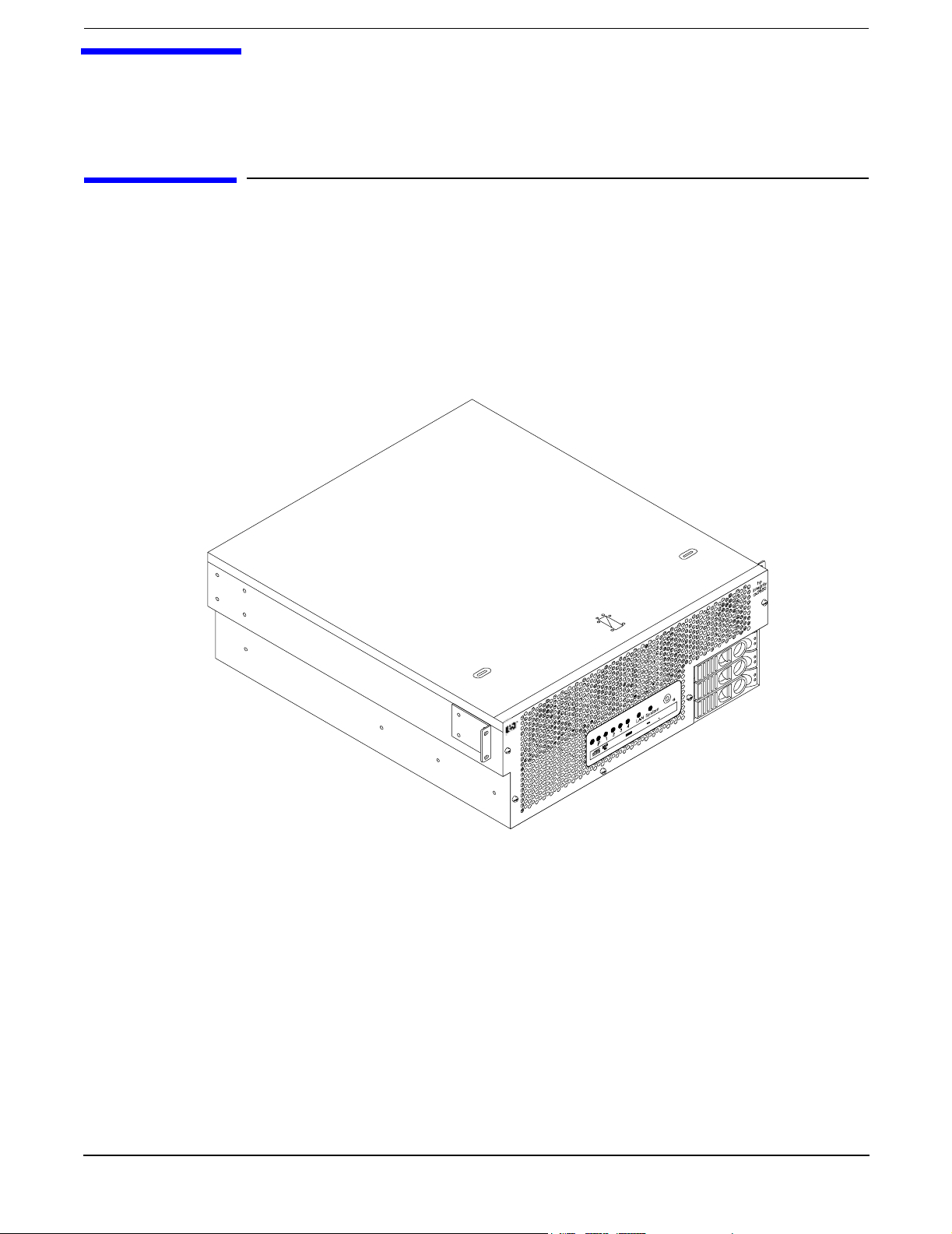
The hp Integrity cx2600 Server (Regulatory Model No. RSVLA-0303-DC) is a 1- or 2-way, IA-64, carrier grade
server based on the Itanium processor family architecture. This server is NEBS level-3 compliant and is
intended for Telco users. The hp Integrity cx2600 Server accommodates 1 or 2 processors, from 4 to 12 DIMMs
(providing 1 to 24 GB of memory), and internal peripherals including up to 3 disks and a CD/DVD-ROM. Its
high availability features include hot-swap fans and power supplies, and hot-plug disk drives. The hp
Integrity cx2600 Server uses the Debian CG 5.0+ operating system (Linux).
Figure 2-1 hp Integrity cx2600 Server
Chapter 2
chasoblq
11
Page 12

Server Overview and Unpacking
Server Overview
Figure 2-2 hp Integrity cx2600 Server (front view)
LAN4321 System
chasfront
Figure 2-3 hp Integrity cx2600 Server (rear view)
hp
integrity
cx2600
rearview
Fault
DC Out DC In
Fault
DC Out DC In
12
Chapter 2
Page 13

Server Overview and Unpacking
Unpacking the Server
Unpacking the Server
Hewlett-Packard shipping containers protect their contents under normal shipping conditions. After the
equipment arrives, carefully inspect each carton for signs of shipping damage. If damage is found, document
the damage with photographs and contact the transport carrier immediately.
If the equipment has any damage, a damage claim form must be obtained from the shipping representative.
The customer should complete the form and return it to the shipping representative.
Unpacking the Server
WARNING Because a filled hp Integrity cx2600 shipping container may weigh as much as 95
pounds (43 kilograms), two people should lift the container together. Do not lift or
carry the HP Server alone. The unit should be transported on a cushioned, wheeled
cart or carrier. Failure to heed this warning could result is serious personnel injury.
Removing the HP Server from the Shipping Container
WARNING The hp Integrity cx2600 Server may weigh as much as 95 pounds (43 kilograms). Two
people are required to lift the unit and remove packing material. Failure to heed this
warning could result in serious personal injury or damage to the HP Server.
The hp Integrity cx2600 Server is shipped in a standard container, but is cushioned against shock. Open the
top of container and lift the HP Server and packing material from the box. Place the unit on a level work
surface and remove the packing material.
Installing the HP Server into a Rack
HP Rack
Any hp Integrity cx2600 Server that is to be installed into a rack is shipped with a mounting kit or equipment
slides. With every mounting kit and slides comes an installation guide. Follow the steps in this installation
guide to determine where and how to place the server into the rack.
Non-HP Rack
There is a guide for evaluating the installation of HP equipment in non-HP racks. This document should be
utilized when there is a need to evaluate and qualify whether any HP equipment can be installed,
maintained, and serviced in a non-HP rack. The guide is located on the Web at:
http://www.hp.com/racksolutions.
Once there, select “mounting information” from the menu on the left side, then select the guide titled
Mounting in Non-HP Racks.
Chapter 2
13
Page 14

Server Overview and Unpacking
Unpacking the Server
14
Chapter 2
Page 15

3 Installing Additional Components
Safety Information
This chapter describes installing additional or optional hardware to your hp Integrity cx2600 Server.
Follow the procedures listed below to ensure safe handling of components and to prevent harm to both you
and the HP Server:
• Use an antistatic wrist strap and a grounding mat, such as those included in the Electrically Conductive
Field Service Grounding Kit (HP 9300-1609).
• Handle accessory boards and components by the edges only. Do not touch any metal-edge connectors or
any electrical components on accessory boards.
• Do not wear clothing that is subject to static charge build-up, such as wool or synthetic materials.
WARNING Hazardous energy is present inside the HP Server. Always remove power from
the server before working inside the unit. Serious injury may result if this
warning is not observed.
Service Tools Required
Service of this product may require one or more of the following tools:
• Electrically Conductive Field Service Kit (P/N 9300-1609)
• 1/4 inch flat blade screwdriver
• ACX-15 torx screwdriver
• ACX-10 torx screwdriver
• IPF CPU install tool (P/N 5069-4551—supplied with processors shipped separately)
Accessing a Rack Mounted Server
The hp Integrity cx2600 Server is designed to be rack mounted. The following procedure explains how to gain
access to an hp Integrity cx2600 Server that is mounted in an approved rack.
WARNING Ensure that all anti-tip features (front and rear anti-tip feet installed; adequate
ballast properly placed, and so on) are employed prior to extending the server.
Chapter 3
15
Page 16

Installing Additional Components
Accessing a Rack Mounted Server
Installing Components When the Server is in a Rack
Power supplies, disks and fans can be installed when the server is fully inserted into a rack. Only front and
rear access is required.
Internal components can be accessed by removing the top cover. Proceed as follows:
WARNING Hazardous energy is present inside the HP Server. Always remove power from the
server before working inside the unit. Serious injury may result if this warning is
not observed.
NOTE Ensure that there is enough area (approximately 1.5 meters [5 ft.]) to fully extend the server
out the front of the rack and work on it.
Step 1. Turn off and disconnect system power. Disconnect power at the DC source end of the power cable(s),
using the disconnect device that is part of the rack or facility power system.
Step 2. Label and disconnect all cables from the unit rear panel connectors.
Step 3. Remove or loosen (as appropriate) the screws that fasten the server to the rack.
Step 4. If the server is slide-mounted, slowly pull the chassis forward (or push from the rear) to extend the
chassis from the rack. The server is fully extended when the rail clips are locked in place. If the
server is tray-mounted, it is not held in the rack and can fall from its mounting. Do not extend the
server from the rack but remove it from the rack for internal access.
Step 5. Remove the top cover. Refer to “Removing the Top Cover” on page 25.
Remove the Server from a Rack
WARNING Do not attempt to lift the server alone. The server may weigh as much as 32
kilograms (70 lbs). Serious injury may result if this warning is not observed.
NOTE Ensure that there is enough area (approximately 1.5 meters [5 ft.]) to fully extend the server
out the front of the rack and work on it.
To remove the server from the rack, perform the following steps:
Step 1. Turn off and disconnect system power. Disconnect power at the DC source end of the power cable(s),
using the disconnect device that is part of the rack or facility power system.
Step 2. Label and disconnect all cables from the unit rear panel connectors.
Step 3. Remove or loosen (as appropriate) the screws that fasten the server to the rack.
Step 4. Label and disconnect the rack/facility ground cable from the chassis rear panel. (See Figure 3-1.)
16
Chapter 3
Page 17
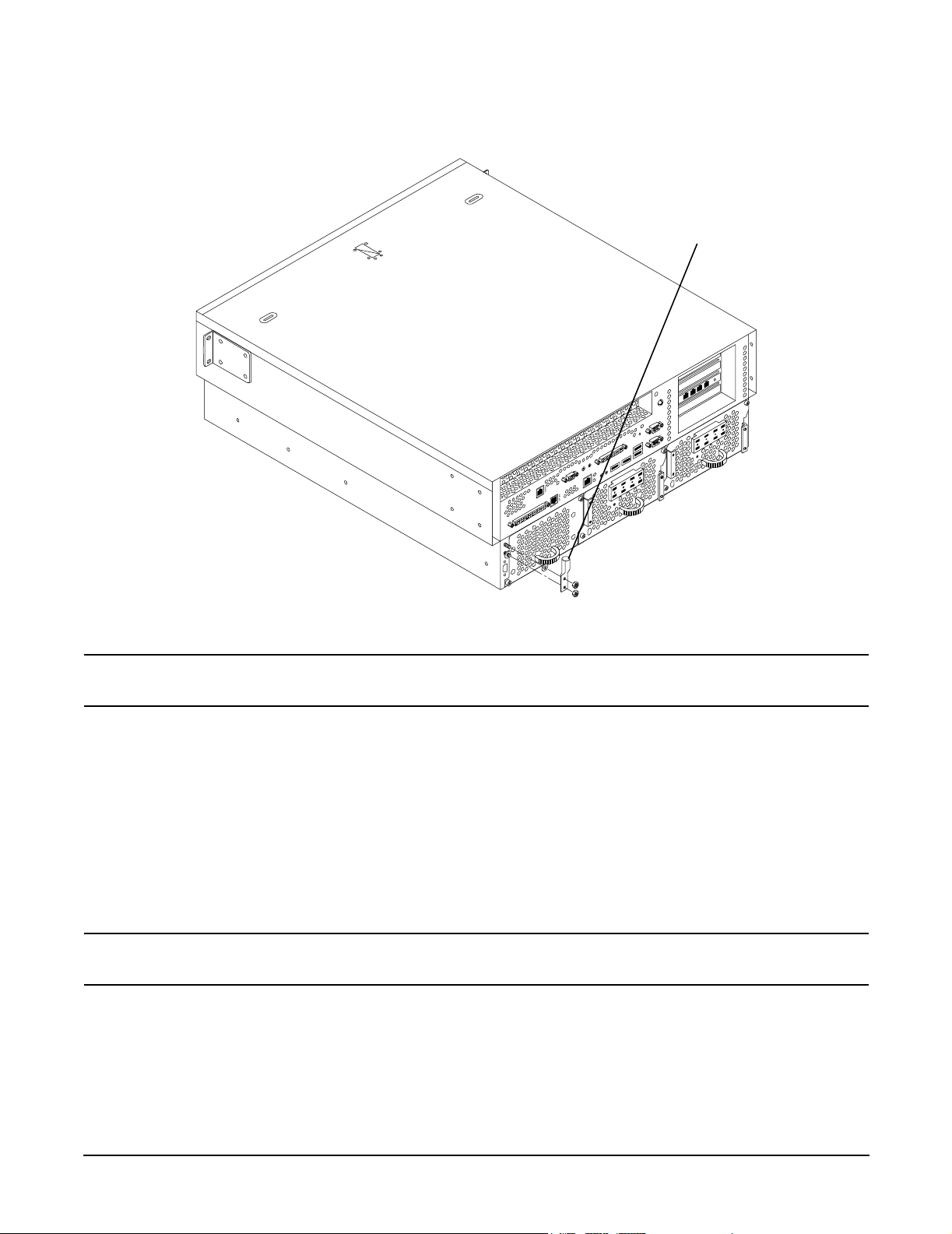
Figure 3-1Chassis Ground Lug
Installing Additional Components
Accessing a Rack Mounted Server
Chassis
Ground
Lug
chasgndlug
WARNING Do not attempt to lift the server alone. The server may weight as much as 32
kilograms (70 lbs). Serious injury may result if this warning is not observed.
Step 5. If the server is slide-mounted, slowly pull the chassis forward (or push from the rear) to extend the
chassis from the rack. The server is fully extended when the rail clips are locked in place. Do not
extend tray-mounted servers. Tray-mounted servers are not locked in place and can fall if extended
from rack.
Step 6. Disengage the slides or mounting hardware and take the server to a static-free work station.
Install the Server into a Rack
To insert the server into the rack, perform the following steps:
WARNING Do not attempt to lift the server alone. The server may weigh as much as 32
kilograms (70 lbs). Serious injury may result if this warning is not observed.
Step 1. Engage the server slides or mounting kit, as appropriate.
Step 2. Slide the server inward and push the server into the rack until it is in position.
Step 3. Connect server cables to rear-panel connectors.
Step 4. Connect rack/facility ground cable to chassis ground lug. (See Figure 3-1.)
Chapter 3
17
Page 18
Installing Additional Components
Installing Disk Drives
Step 5. Replace or tighten (as appropriate) the screws that fasten the server to the rack.
Installing Disk Drives
The supported configuration of an hp Integrity cx2600 Server includes 1, 2 or 3 Low-Voltage-Differential
(LVD), hot-plug disk drives. If any of the three disk drives are not installed a disk filler must be installed in
the disk location.
Hot-plug disk drives are located at the front of the server. The following sections describe removing and
reinstalling a disk drive.
CAUTION A hot-plug device may require interaction with the operating system before the device can be
safely removed from or installed into the server. Determine if the operating system supports
replacement of disk drives while the operating system is running. If the operating system does
not support this feature, shut down the operating system before performing these procedures.
Failure to observe this caution could result in system failure.
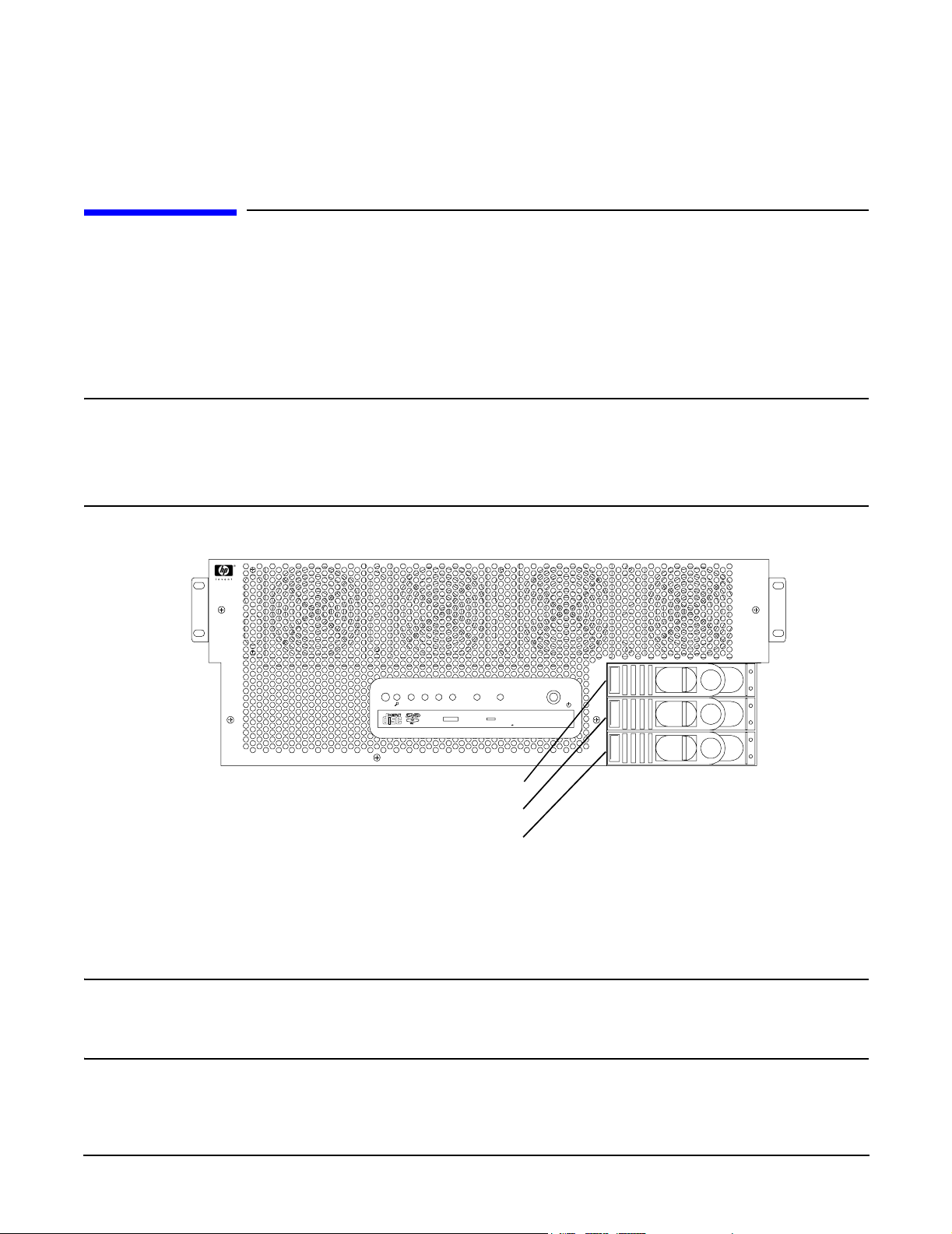
Figure 3-2 Front View of the hp Integrity cx2600 Server
hp
integrity
cx2600
LAN4321 System
chasfront
Disk Slot 2
Disk Slot 1
Disk Slot 0
Removing Hot-Plug Disk Drives
Slots are provided for up to three hot-plug disk drives in your hp Integrity cx2600 Server. When disk drives
are not installed, filler assemblies are installed to prevent air leakage and ensure adequate cooling.
NOTE The filler assemblies are removed and installed in the same manner as described for hard
drives. Simply pull the dummy release lever to pull the filler from the server.
When inserting a filler, simply push the filler into position.
To remove a hot-plug disk drive, perform the following steps:
18
Chapter 3
Page 19
Installing Additional Components
Installing Disk Drives
CAUTION The disk drives in the hp Integrity cx2600 Server are not hot-swappable. They are merely
hot-pluggable. A manual software procedure may be required in order to safely remove or
insert disk drives while the system is running. To avoid damage to the hard drives:
Refer to the documentation provided with the disk drive for additional information about
removing and inserting a drive.
Refer to the operating system documentation for additional information about removing and
inserting hot-plug assemblies.
Step 1. If required (OS does not support hot-plugging devices), stop the operating system.
Step 2. Squeeze inward on the colored release clip and pull the release lever to pull the drive from the
server chassis.
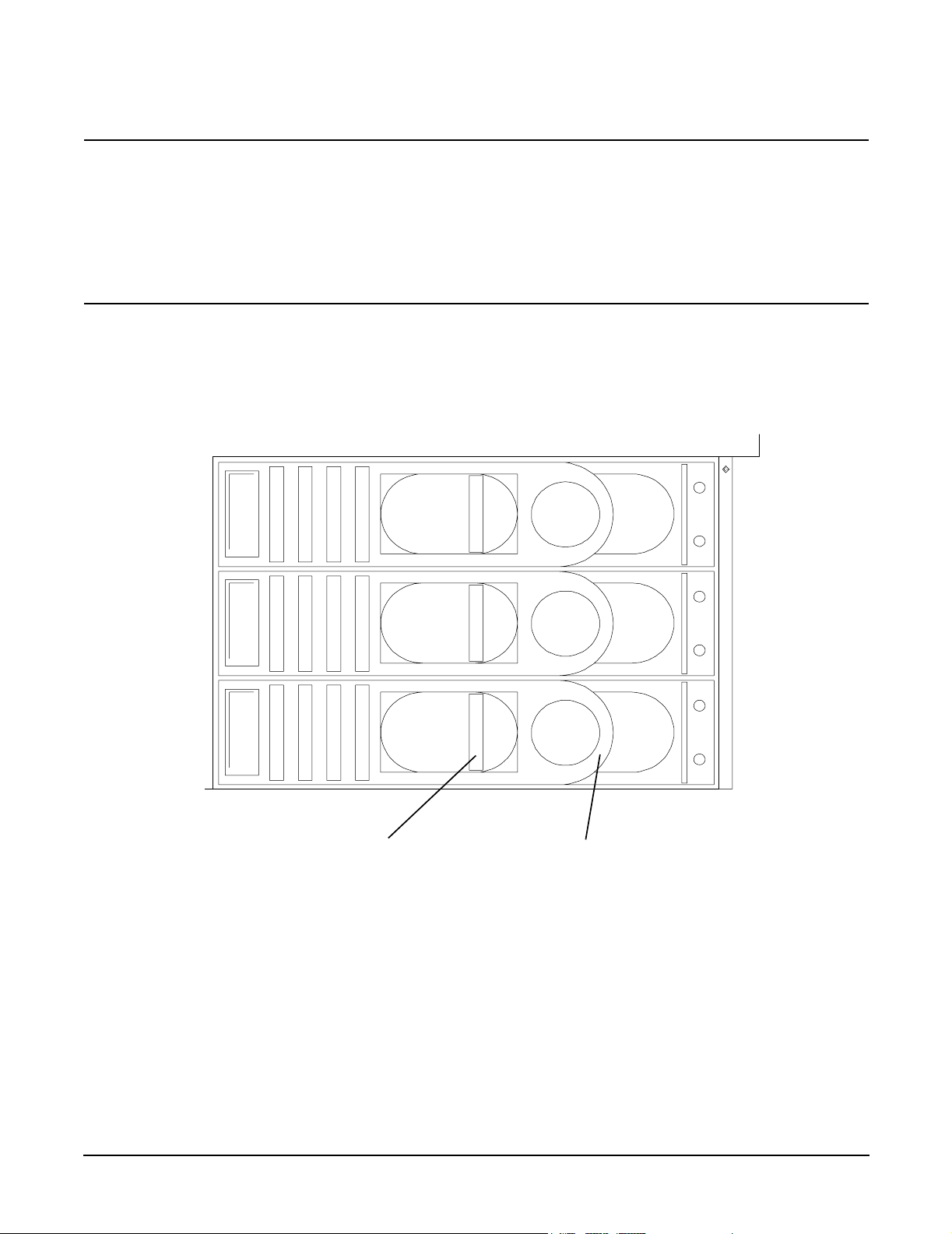
Figure 3-3Disk Drives in Server
2
1
0
S
C
S
I
dskdrvfrnt1
Release Clip
Release Lever
Installing Hot-Plug Disk Drives
Up to three hot-plug disk drives may be installed in your hp Integrity cx2600 Server. Always use low profile
disk drives (1.0" height) in your server.
To install a hot-plug disk drive, perform the following steps:
Step 1. If required (OS does not support hot-plugging devices), stop the operating system.
Step 2. If a disk filler is installed, remove it by pulling the release lever.
Step 3. With the release lever pulled out, slide a hot-plug hard disk into the disk slot until it is seated.
Chapter 3
19
Page 20

Installing Additional Components
Hot-Swap Power Supply Units
Step 4. Press the release lever until it is flush with the front of the server. You will hear it click as it locks
into position.
Step 5. If the operating system was stopped in step 1, reset the system to the EFI Boot Maintenance Menu,
to rescan the hard drives.
Step 6. If the operating system was stopped in step 1, use the EFI shell map command to verify that the
newly inserted drive has been correctly installed. Refer to Chapter 5 of this guide (Cable
Connections) and to the hp Integrity cx2600 Operation and Maintenance Guide for information
about connecting a console and using the EFI shell. (The hp Integrity cx2600 Operation and
Maintenance Guide is included on the CD provided with your system).
Hot-Swap Power Supply Units
The supported configuration of an hp Integrity cx2600 Server requires that two power supplies be installed.
During normal operations, the two power supplies share the load. Each provides power via a separate power
rail. A single power supply can provide all power needed for normal operations, but a second power supply is
installed to provide backup capability.
Hot-swap power supplies 1 and 2 are located at the rear of the chassis. The power supplies are identical and
interchangeable.
NOTE A hot-swap device does not require interaction with the operating system before the device is
removed from or installed into the server. If the second power supply is functioning correctly, a
power supply can be powered down and removed with no effect on server operations.
The power to the server (other power supply) does not have to be off to remove or replace a
hot-swap power supply.
20
Chapter 3
Page 21
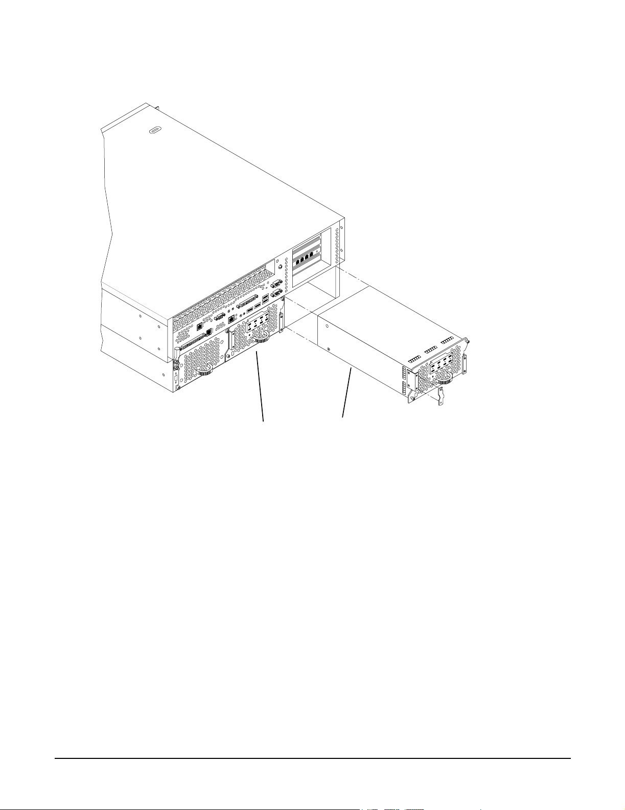
Figure 3-4 Hot-Swap Power Supplies
Installing Additional Components
Hot-Swap Power Supply Units
chaspsxtnd
Power
Supply 1
Power
Supply 2
Removing and Replacing a Hot-Swap Power Supply
A power supply can be replaced while the server is installed in a rack, with the server operating normally.
Removal and installation of a power supply will have no effect on operations if the other power supply is
functioning correctly. To remove and replace a hot-swap power supply, perform the following steps:
Chapter 3
21
Page 22
Installing Additional Components
Hot-Swap Power Supply Units
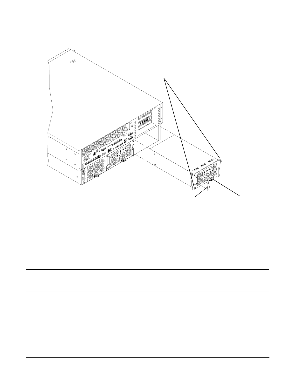
Figure 3-5 Removing a Hot-Swap Power Supply
Mounting
Screws
chaspsxtnd
Cable
Clamp
Handle
Step 1. If rack-mounted, it may be necessary to extend a slide-mounted server out from the rack for better
access. If needed, slide the server out to the fully extended position.
Step 2. Remove power from the power supply being replaced. Disconnect power at the DC source end of the
power cable, using the disconnect device that is part of the rack or facility power system.
Step 3. Loosen the two knurled knobs on the power supply cable clamp to release the power feed leads.
Step 4. Press up on the two lower tabs of the terminal barrier strip cover to snap off the cover.
WARNING Always check that the power cable is not connected to a power source
before attempting to disconnect the power cable from power supply
terminals. Failure to heed this warning could result in injury.
Step 5. Loosen or remove (as appropriate) the screws that secure power cable leads to the terminal strip
and disconnect the power cable leads from the power supply.
Step 6. Reinstall the terminal strip hardware and the barrier strip cover (removed in steps 4 and 5) to
prevent loss. Hang the cover on the upper tabs and snap the cover into place.
Step 7. Using an ACX-15 torx screwdriver, loosen the two captive mounting screws that secure the power
supply to the server chassis.
22
Chapter 3
Page 23
Installing Additional Components
Front Grill and Top Cover
Step 8. Pull the power supply from the server chassis by pulling the curved handle.
Step 9. Orient the replacement power supply such that the securing screws are aligned with the
corresponding holes in the server chassis. Gently push the power supply into position.
Step 10. When the power supply is fully inserted into the server chassis, tighten the two mounting screws to
secure the power supply in place.
Step 11. Press up on the two lower tabs on the terminal barrier strip cover to snap off the cover.
WARNING Always check that the power cable is not connected to a power source
before attempting to connect the power cable to power supply terminals.
Failure to heed this warning could result in injury.
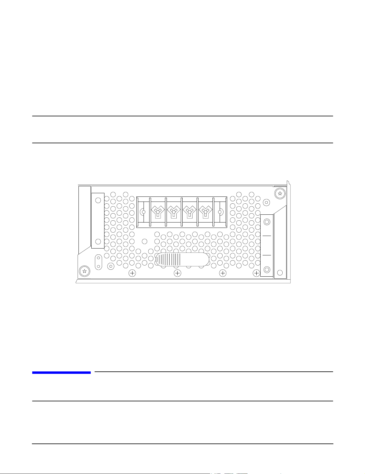
Step 12. Connect the power cable leads to the power supply terminals. (Connect the leads as shown in
Figure 3-6.)
Figure 3-6Power Supply Terminals
++––
Fault
DC Out DC In
psrearpnl2
Step 13. Reinstall the terminal barrier strip cover (removed in step 11). Hang the cover on the upper tabs
and snap the cover into place.
Step 14. Route the power cable through the power supply cable clamp and tighten the two knurled knobs to
secure the cable in place.
Step 15. Connect the power cable to the DC power source.
Front Grill and Top Cover
CAUTION Operation of the HP Server without the front grill and top cover in place will make the server
susceptible to EMI and overheating problems, which can result in system failure. Keep the
front grill and top cover in place during normal operation.
Chapter 3
23
Page 24
Installing Additional Components
Front Grill and Top Cover
Observe all ESD safety precautions while performing this procedure. Failure to follow ESD
safety precautions could result in damage to the server.
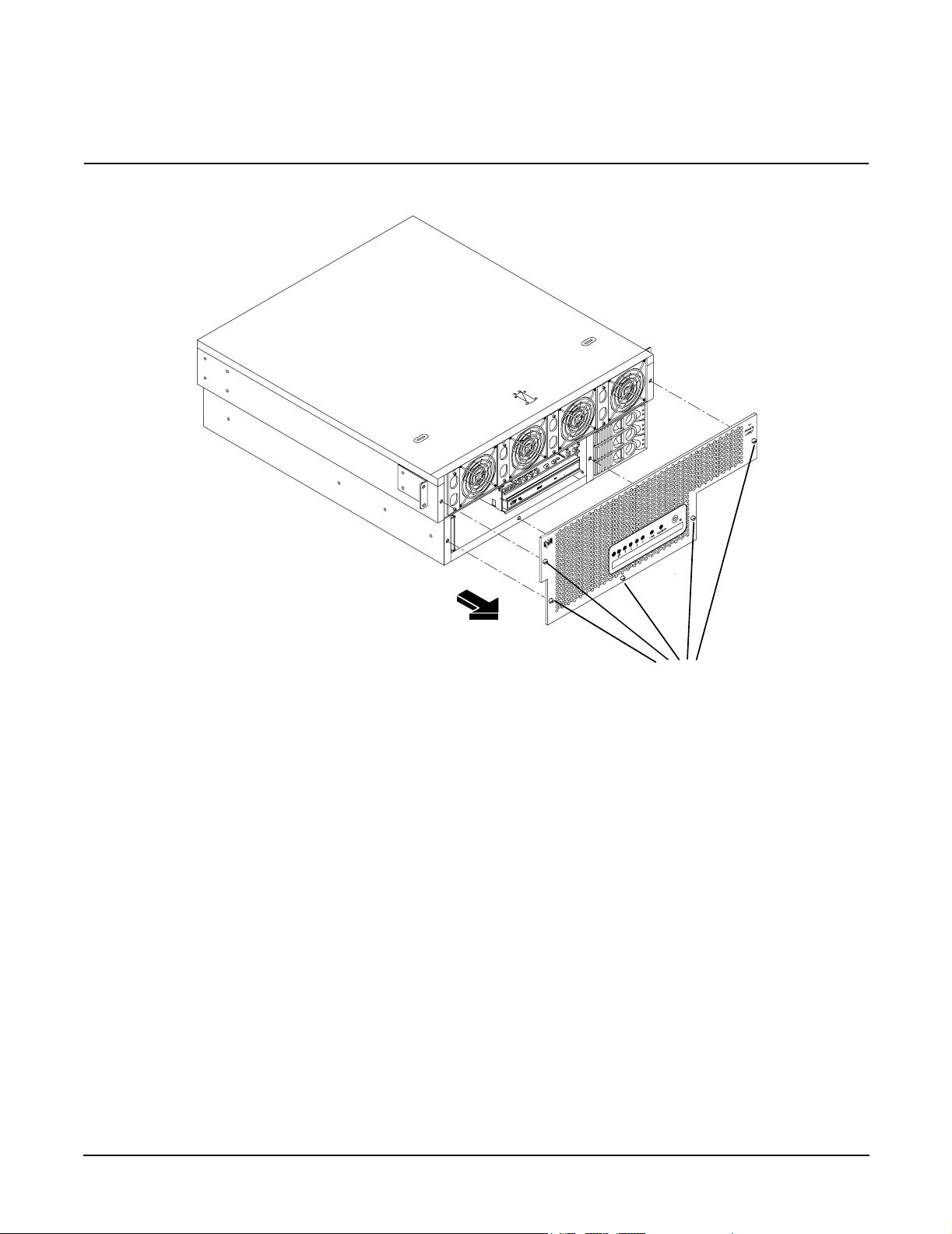
Figure 3-7 Removing the Front Grill
chasfrntoff
Captive Screws
Removing the Front Grill
You must remove the front grill for access to the front mounted fans or the optical drive. To remove the front
grill, perform the following steps:
Step 1. Using an ACX-15 torx screwdriver, loosen the five captive screws that secure the grill to the
chassis.
Step 2. Pull the grill from the front of the server chassis.
Replacing the Front Grill
To replace the front grill, perform the following steps:
Step 1. Hold the grill against the front of the server chassis, in mounting position.
Step 2. Tighten the five captive screws to secure the grill to the server chassis.
24
Chapter 3
Page 25

Removing the Top Cover
Figure 3-8 Removing the Top Cover
Holding
Installing Additional Components
Front Grill and Top Cover
Cover
Screw
Slots for Tabs
in Cover
(2 each side)
ESD Ground
Jack (Connect
wrist strap here)
topupwguide
Cover Tabs
Slots for Tabs
To remove the top cover, perform the following steps:
Chapter 3
25
Page 26

Installing Additional Components
Front Grill and Top Cover
WARNING Hazardous energy is present within the server when power is applied. Do not
remove the server top cover without first turning off and disconnecting power.
Always replace the top cover before turning the system on.
Step 1. Turn off and disconnect system power. Disconnect power at the DC source end of the power cable(s),
using the disconnect device that is part of the rack or facility power system.
Step 2. Slide the server out from the rack until it stops. Refer to “Accessing a Rack Mounted Server” on
page 15.
Step 3. If desired, remove the server from the rack at this time. Refer to “Remove the Server from a Rack”
on page 16.
Step 4. Using an ACX-15 torx screwdriver, loosen the captive screw that holds the top cover in place.
Step 5. Slide the cover toward the rear of the server chassis and lift it straight up.
Replacing the Top Cover
To replace the top cover, perform the following steps:
Step 1. Align each pair of tabs on the left and right sides of the cover with the corresponding slots in the
chassis. Set the cover in place on the chassis.
Step 2. Align the three tabs on the front of the cover with the corresponding apertures at the top front of
the chassis and insert the tabs into the slots.
Step 3. Push the cover forward until it seats on the chassis.
Step 4. Tighten the captive screw to secure the cover in place.
26
Chapter 3
Page 27

Installing Additional Components
Hot-Swap Chassis Fan Units
Hot-Swap Chassis Fan Units
There are five hot-swap chassis fan units in the HP Server. Fan units 1, 2, 3 and 4 are accessible from the
front of the chassis. Fan unit 5 is accessible from the rear of the chassis. Fan units 1, 2, 3 and 4 are identical
and interchangeable.
If a fan failure is total (both rotors), or if the fan has been removed from the chassis for more than 30 seconds,
a system will log the event as a critical error. A critical error will cause the System LED to flash red and will
require a reboot to reset the error status. A total fan failure (including removal) for more than 2 minutes will
result in system shutdown. If you are hot-swapping a fan assembly in response to an error message, and the
system is operating normally, hot-swapping the fan in less than 30 seconds will eliminate the requirement for
a system reboot. Hot-swapping a fan in less than 2 minutes will allow continued operation and prevent
automatic shutdown.
CAUTION Operating the server with the front grill removed will risk EMI. Operate the server with the
front grill removed only when hot-swapping a fan. Always replace the front grill immediately
after replacing the fan.
Observe all ESD safety precautions while performing this procedure. Failure to follow ESD
safety precautions could result in damage to the server.
NOTE A hot-swap device does not require interaction with the operating system before the device is
removed from or installed into the server.
The power to the server does not have to be off to remove or replace a hot-swap chassis fan unit.
Chapter 3
27
Page 28
Installing Additional Components
Hot-Swap Chassis Fan Units
Removing and Replacing a Front Panel Hot-Swap Fan
Figure 3-9 Removing a Front Panel Hot-Swap Fan
Fan 1
chasfan1xtnd
Fan 2
Captive
Screws
Fan 3
Fan 4
The server does not need to be removed or extended from the rack to allow fan replacement. To remove and
replace a hot-swap fan from the front of the server chassis, perform the following steps:
Step 1. Remove the front grill. Refer to “Removing the Front Grill” on page 24.
Step 2. Using an ACX-15 torx screwdriver, loosen the two captive screws on the plastic fan extractor
handle (left side of fan).
CAUTION Hot-swapping a fan can interrupt system operation. If you are hot-swapping a fan
assembly in response to an error message, and the system is operating normally,
hot-swapping the fan in less than 30 seconds will eliminate the requirement for a
system reboot. Hot-swapping the fan in less than 2 minutes will allow continued
operation and prevent automatic shutdown.
Step 3. Using the extractor handle, pull the fan from the server chassis.
Step 4. Orient the replacement fan such that the extractor handle is at the left. Insert the fan into the
chassis opening and press firmly into place.
Step 5. Tighten the two captive screws that secure the fan in place.
28
Chapter 3
Page 29

Removing and Replacing a Rear Panel Hot-Swap Fan
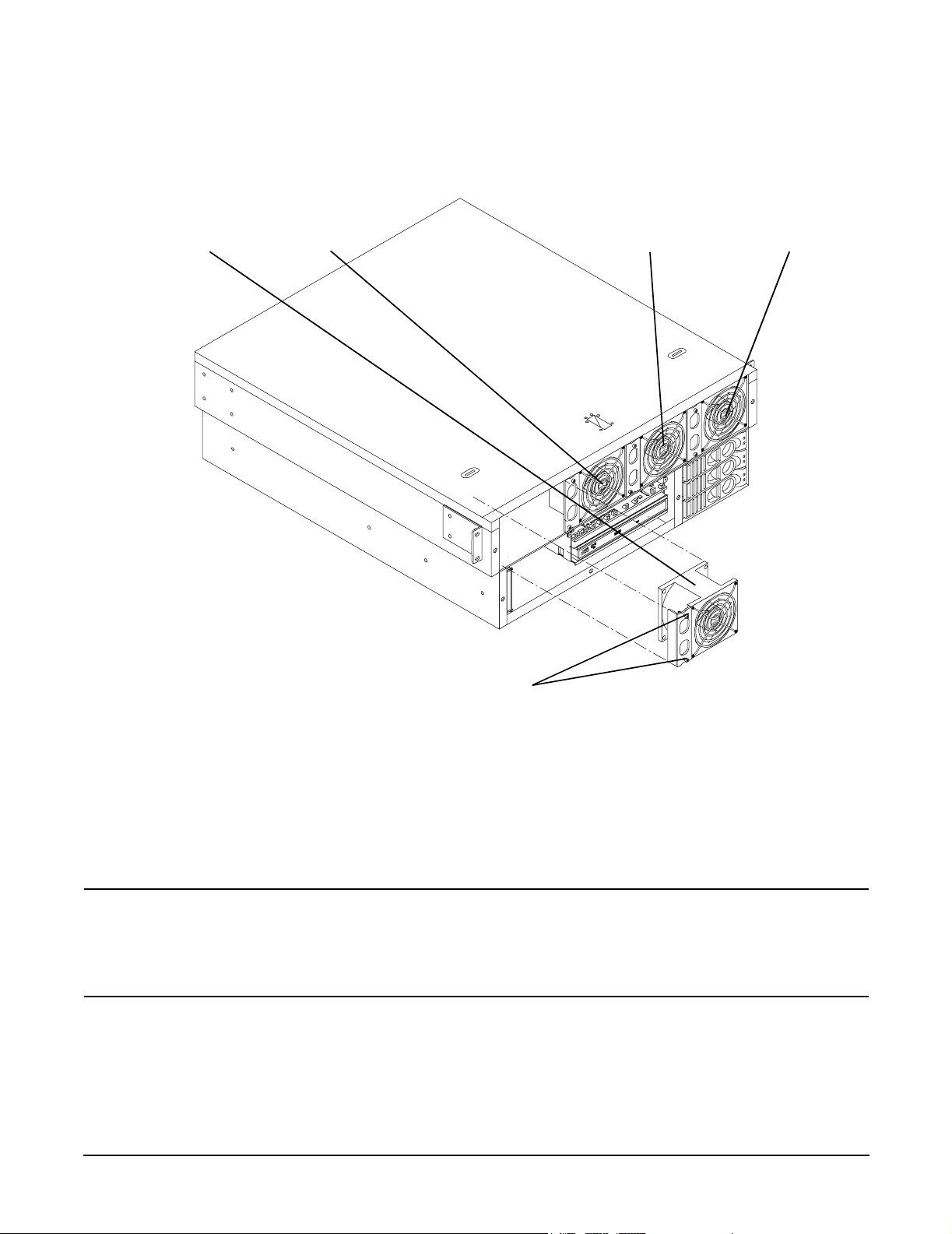
Figure 3-10 Removing a Rear Panel Hot-Swap Fan
Installing Additional Components
Hot-Swap Chassis Fan Units
Fan 5
Mounting
Screws
chasfan5xtnd
To remove and replace the hot-swap fan from the rear of the server chassis, perform the following steps:
NOTE The server does not need to be removed from the rack to allow fan replacement.
Step 1. If rack-mounted, it may be necessary to extend a slide-mounted server out from the rack for better
access. If needed, slide the server out to the fully extended position.
Chapter 3
29
Page 30

Installing Additional Components
Hot-Swap Chassis Fan Units
Step 2. Using an ACX-15 torx screwdriver, loosen the two captive screws that secure the fan unit to the
server chassis.
CAUTION Hot-swapping a fan can interrupt system operation. If you are hot-swapping a fan
assembly and the system is operating normally, hot-swapping the fan in less than 30
seconds will eliminate the requirement for a system reboot. Hot-swapping the fan in
less than 2 minutes will allow continued operation and prevent automatic shutdown.
Step 3. Pull the fan assembly from the server chassis by pulling the curved handle.
Step 4. Orient the replacement fan assembly such that the curved handle is at the bottom. Gently push the
fan unit into position.
Step 5. Tighten the two captive screws that secure the fan unit to the server chassis.
30
Chapter 3
Page 31

Installing Additional Components
PCI Card Installation
PCI Card Installation
The hp Integrity cx2600 Server has four 64-bit, 133 MHz PCI-X accessory card sockets located in a removable
card cage. The PCI card cage must be removed before PCI cards can be removed or installed. The following
sections remove and open the card cage, remove and install PCI cards, and reinstall the card cage.
Removing the PCI Card Cage Assembly
To remove the PCI card cage assembly, perform the following steps:
Step 1. If rack mounted, extend a slide-mounted server out from the rack until it stops. Refer to “Accessing
a Rack Mounted Server” on page 15.
Step 2. Turn off the system. Disconnect all external cables.
Step 3. If desired, remove the server from the rack and place it on an ESD-protected work surface. Refer to
“Remove the Server from a Rack” on page 16.
WARNING Ensure that the system is powered down and all power sources have been
disconnected from the server prior to removing or replacing the PCI card
cage assembly.
Voltages and hazardous energy can be present at various locations within
the server whenever a power source is connected. This hazard is present
even when the power switch is in the off position.
Failure to observe this warning could result in personal injury or damage
to equipment.
Step 4. Remove the top cover from the chassis. Refer to “Removing the Top Cover” on page 25.
CAUTION Observe all ESD safety precautions while performing this procedure. Failure to
follow ESD safety precautions could result in damage to the server.
Step 5. Pull up on the PCI card cage release lever (colored lever) and the back edge of the card cage, then
lift the card cage out of the server chassis.
Chapter 3
31
Page 32

Installing Additional Components
PCI Card Installation
Figure 3-11Removing the PCI Card Cage
PCI Card
Cage
Release
Lever
chaspciccdwn
Step 6. Place the card cage on an ESD-protected work surface.
Step 7. Orient the card cage such that PCI card connectors (within the card cage) are at the bottom, when
viewed through the open side of the card cage, and cards can be removed by lifting them from the
sockets.
Step 8. Remove the cover that is now on top of the card cage by sliding the cover toward the rear of the card
cage and lifting the cover. Remove the cover from the card cage.
NOTE The four connectors within the card cage are identical and have the same capabilities. A
compatible PCI card can be installed in any slot.
Removing a PCI Card
NOTE The PCI card cage must be removed from the server chassis to allow access to the PCI cards.
To remove a PCI card, perform the following steps:
Step 1. Remove the PCI card cage from the server chassis. Refer to “Removing the PCI Card Cage
Assembly” on page 31.
Step 2. Remove the cover from the PCI card cage.
32
Chapter 3
Page 33

Installing Additional Components
PCI Card Installation
CAUTION Observe all ESD safety precautions while performing this procedure. Failure to
follow ESD safety precautions could result in damage to the server.
Step 3. If a cable will block card removal, or if it is connected to the card to be removed, disconnect the
cable(s) from card connector(s) at this time.
Step 4. Using an ACX-15 torx screwdriver, remove the retaining screw that secures the card in place. See
Figure 3-12.
Figure 3-12PCI Card Retaining Screws
Card
Retaining
Screws
pciccscrw2
Step 5. Grasp the card by the two opposing edgers and lift the card from the socket.
Step 6. If no card will be installed in the empty socket, install a blank panel in the bulkhead opening at the
end of the card cage. The blank panel is necessary to ensure correct air flow and EMI protection
when the card cage is installed in a working server.
Installing a PCI Card
NOTE The PCI card cage must be removed from the server chassis to allow installation of PCI cards.
The four connectors in the PCI card cage are identical and have the same capabilities. A compatible PCI card
may be installed in any slot. To install a PCI card, perform the following steps:
Step 1. Remove the PCI card cage from the server chassis. Refer to “Removing the PCI Card Cage
Assembly” on page 31.
Chapter 3
33
Page 34

Installing Additional Components
PCI Card Installation
Step 2. Remove the cover from the PCI card cage.
CAUTION Observe all ESD safety precautions while performing this procedure. Failure to
follow ESD safety precautions could result in damage to the server.
Step 3. If a blank panel is installed at the end of the card cage (for the card position/socket which will be
used), remove the blank panel.
Step 4. Grasp the card to be installed by opposing edges and orient the card such that its connector is
aligned with the card cage socket and the PCI interface connector can be extended through the
opening at the end of the card cage. Insert the card into the desired socket.
Step 5. Secure the card in the card cage using the retaining screw provided.
Step 6. Connect any cables (if appropriate) to card sockets at this time.
Installing the PCI Card Cage Assembly
To install the PCI card cage assembly, perform the following steps:
WARNING Ensure that the system is powered down and all power sources have been
disconnected from the server prior to removing or replacing the PCI card cage
assembly.
Voltages and hazardous energy can be present at various locations within the server
whenever a power source is connected. This hazard is present even when the power
switch is in the off position.
Failure to observe this warning could result in personal injury or damage to
equipment.
CAUTION Observe all ESD safety precautions while performing this procedure. Failure to follow ESD
safety precautions could result in damage to the server.
Step 1. If the card cage cover has been removed, insert the cover tabs (fan end of cover) into the
corresponding slots on the card cage and press the cover into position on the card cage. Slide the
cover toward the front of the card cage to secure the cover in place.
Step 2. Orient the PCI card cage as shown in Figure 3-13. Lift the release lever and hold it in the open
position. Lower the card cage into position and press gently to seat card cage connectors.
34
Chapter 3
Page 35

Figure 3-13Installing the PCI Card Cage
PCI Card
Cage
Installing Additional Components
PCI Card Installation
Release
Lever
chaspciccup
Step 3. Press the release lever down (into position) to lock the card cage in place in the chassis.
Step 4. Reinstall the chassis top cover. Refer to “Replacing the Top Cover” on page 26.
Step 5. Reconnect rear panel cables, and turn on the system.
Step 6. Run info io at the EFI shell to verify that the PCI card(s) has been correctly installed.
Chapter 3
35
Page 36
Installing Additional Components
Installing Processors and Memory
Installing Processors and Memory
This section provides information about removing and installing processors and memory. The processors and
memory are located on the system board and are accessible after removing the top cover and air guides.
Processor 0 (CPU 0) is located closer to the chassis side panel and processor 1 (CPU 1) is located closer to the
DIMM sockets. (See Figure 3-14.)
Your hp Integrity cx2600 Server may be delivered with one or two processors installed. You may wish to
install the second processor, or replace the processors with newer, compatible processors. Additional or larger
DIMMs may be available for installation. The following sections provide detailed procedures for removal and
installation of processors and memory.
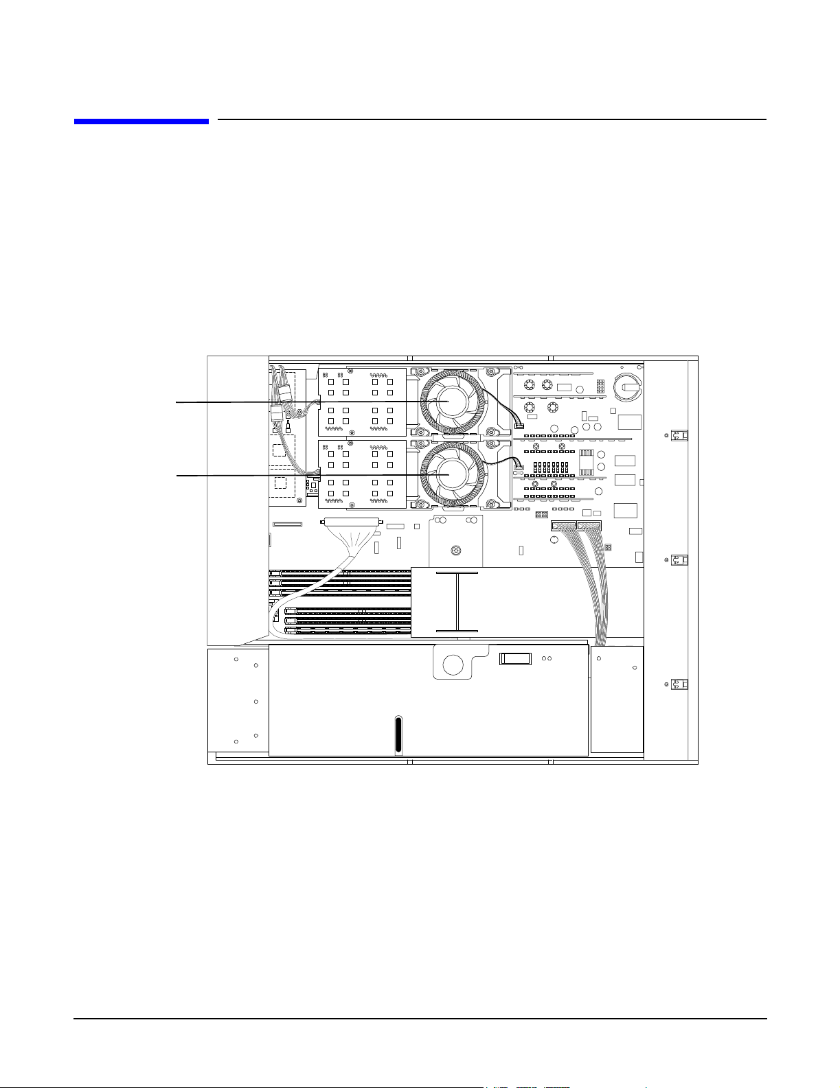
Figure 3-14 Processors in Server Chassis (Top Cover Removed)
CPU 0
CPU 1
chastop2cpus
Removing a Processor
To remove a processor, proceed as follows:
F
R
O
N
T
Step 1. If rack-mounted, extend the server out from the rack on slides until it stops. Refer to “Accessing a
Rack Mounted Server” on page 15.
36
Chapter 3
Page 37

Installing Additional Components
Installing Processors and Memory
WARNING Voltages and hazardous energy can be present at various locations within
the server whenever a power source is connected. This hazard is present
even when the power switch is in the off position.
Ensure that the system is powered down and all power sources have been
disconnected from the server prior to performing the following procedures.
Failure to observe this warning could result in personal injury or damage
to equipment.
Step 2. Turn off the system. Disconnect all external cables.
Step 3. If desired, remove the server from the rack and place it on an ESD-protected work surface. Refer to
“Remove the Server from a Rack” on page 16.
Step 4. Remove the chassis top cover. Refer to “Removing the Top Cover” on page 25.
CAUTION Observe all ESD safety precautions while performing processor removal. Failure to
follow ESD safety precautions could result in damage to the server.
Step 5. Remove the processor airflow guide. (See Figure 3-15).
Figure 3-15Processor Airflow Guide
Processor
Airflow
Guide
chascvroff
Step 6. Unplug the CPU power module cable.
Chapter 3
37
Page 38
Installing Additional Components
Installing Processors and Memory
Step 7. Loosen the power module mounting screws and disconnect the module from its processor by sliding
it toward the back of the chassis.
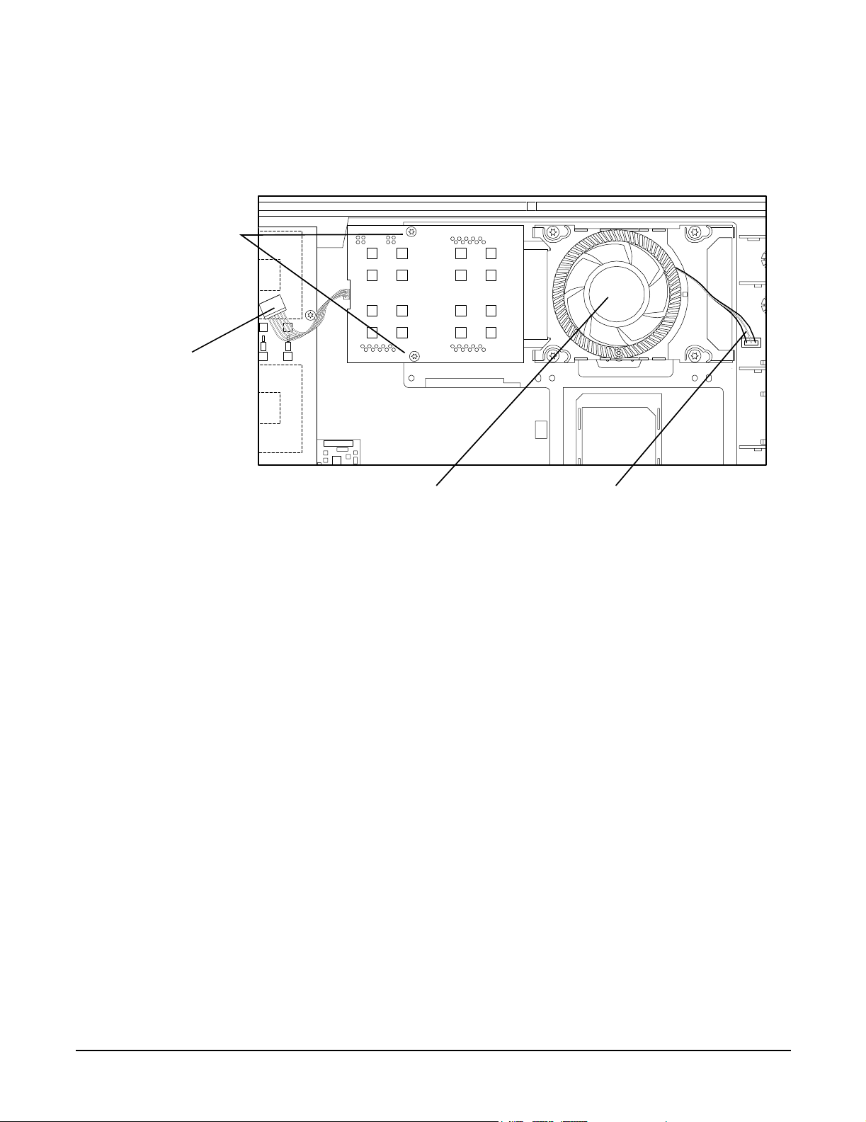
Figure 3-16Disconnecting the Power Module
Power Module
Mounting
Screws
Power
Module
Cable
cpu1wpm1
Processor
Fan
Turbo Fan
Power
Cable
Step 8. Remove the CPU power module from the server chassis.
Step 9. Disconnect the turbo fan power cable.
Step 10. Loosen the four heatsink captive screws using the special processor tool that was shipped with your
processor.
Step 11. Slide the sequencing retainer plate toward the back of the chassis to open the hole in the edge of the
turbo fan heatsink for insertion of the special processor tool into the processor locking mechanism.
38
Chapter 3
Page 39

Figure 3-17Loosen the Turbo Fan Heatsink Screws
Sequencing
Retainer
Plate
Insert Processor
To o l H e re
Installing Additional Components
Installing Processors and Memory
cputopvue
Step 12. Insert the processor tool into the hole that runs down through the edge of the turbo fan heatsink.
Figure 3-18Unlocking the Processor
Insert Processor
To o l H ere
Unlocked
cpusoclock
Locked
Step 13. Unlock the processor locking mechanism by rotating the tool counterclockwise 180 degrees. (See
Figure 3-18).
Step 14. Remove the turbo fan heatsink and processor from the chassis.
Chapter 3
39
Page 40

Installing Additional Components
Installing Processors and Memory
Installing a Processor
The following procedure is applicable to installation of processor 0 or processor 1. Processor 0 must be
installed before installing processor 1. Proceed as follows:
NOTE Installation instructions are provided with replacement processors. Read those instructions
carefully. Changes in processor design (and installation) may have occurred since this
procedure was written. Always follow the instructions provided with a replacement processor.
Step 1. If rack mounted, extend a slide-mounted server out from the rack until it stops. Refer to “Accessing
a Rack Mounted Server” on page 15.
WARNING Voltages and hazardous energy can be present at various locations within
the server whenever a power source is connected. This hazard is present
even when the power switch is in the off position.
Ensure that the system is powered down and all power sources have been
disconnected from the server prior to performing the following procedures.
Failure to observe this warning could result in personal injury or damage
to equipment.
Step 2. Turn off the system. Disconnect all external cables.
Step 3. If desired, remove the server from the rack and place it on an ESD-protected work surface. Refer to
“Remove the Server from a Rack” on page 16.
Step 4. Remove the chassis top cover. Refer to “Removing the Top Cover” on page 25.
CAUTION Observe all ESD safety precautions while performing processor installation. Failure
to follow ESD safety precautions could result in damage to the server.
Step 5. Remove the processor airflow guide. (See Figure 3-15)
Step 6. Ensure that the processor locking mechanism is rotated to the unlocked position. (See Figure 3-18.)
Step 7. Inspect the pins of the processor to be installed. Verify that processor pin(s) are not bent.
Step 8. Use the four locator posts on the heatsink and the turbo fan power cable to properly align the fan
and processor assembly on the system board. The four locator posts will fit in locator holes on the
processor mount of the system board. The turbo fan power cable must be positioned so that it is
located on the side of the heatsink that faces the front of the chassis.
40
Chapter 3
Page 41

Figure 3-19Installing the Turbo Fan and Processor Assembly
Screw 1 (not shown)
(Tighten first)
Screw 4
(Tighten
last)
Locator
Post
Insert Processor
Tool H e r e
Installing Additional Components
Installing Processors and Memory
Screw 3
(Tighten third)
Screw 2
(Tighten
second
Locator
Hole
Locator
Post
Locator
Hole
cpu1noppm3
Step 9. Use the special processor tool shipped with processor assemblies to lock the processor in place on
the system board. To do this, insert the special processor tool into the hole that runs down the side
of the heatsink and rotate it clockwise 180 degrees.
Step 10. Slide the sequencing retainer plate toward the front of the system.
Step 11. Tighten the four captive screws of the heatsink in the order shown in Figure 3-19. Tighten each
screw 1/2 turn, and then tighten the next screw. Continue this sequence until the heatsink is
secured to the system board.
Step 12. Connect the power cable for the processor turbo fan to its connector on the system board.
Step 13. Slide the CPU power module on the system board metal mounting bracket so that the power
module connector aligns with the connector on the processor. Align the two mounting screw holes
on the power module with their screw holes on the system board’s metal mounting bracket. Screw
in the power module mounting screws.
Step 14. Connect the CPU power module power cable.
Step 15. Place the processor airflow guide in position.
Step 16. Install the chassis top cover. Refer to “Replacing the Top Cover” on page 26.
Chapter 3
41
Page 42

Installing Additional Components
Installing Processors and Memory
Step 17. If necessary, reinstall the chassis in the rack. Refer to “Install the Server into a Rack” on page 17.
Step 18. Reconnect power and system cables to rear panel connectors.
Step 19. Turn on the system.
Step 20. Run info cpu at the EFI shell prompt to verify that the processor has been installed correctly. Refer
to Chapter 5 of this guide (Cable Connections) and to the hp Integrity cx2600 Operation and
Maintenance Guide for information about connecting a console and using the EFI shell. (The hp
Integrity cx2600 Operation and Maintenance Guide is included on the CD provided with your
system).
Installing Memory
Your hp Integrity cx2600 Server comes with 4, 8, or 12 DIMMs installed. The system is minimally configured
with 1 GB of memory (four 256 MB DIMMs loaded in quad 0 (slots 0A, 0B, 1A, and 1B). The system is
maximally configured with 24 GB of memory (four 2 GB DIMMs loaded in each of quads 0, 1, and 2 (quad 0
slots 0A, 0B, 1A, and 1B, quad 1 slots 2A, 2B, 3A, and 3B, and quad 2 slots 4A, 4B, 5A, and 5B.
You may replace these DIMMs, or insert DIMMs into unused quads if desired. When adding DIMMs, you
must use a minimum of four like-sized DIMMs in the next available quad.
Supported DIMM Sizes
Supported DIMM sizes are 256 MB, 512 MB, 1 GB, 2 GB. Dissimilar DIMM sizes may be used in the system,
but all four DIMMs in each quad must be identical.
Removing DIMMs
To remove a DIMM, perform the following steps:
WARNING Voltages and hazardous energy can be present at various locations within the server
whenever a power source is connected. This hazard is present even when the power
switch is in the off position.
Ensure that the system is powered down and all power sources have been
disconnected from the server prior to performing the following procedures.
Failure to observe this warning could result in personal injury or damage to
equipment.
Step 1. If rack mounted, extend a slide-mounted server out from the rack until it stops. Refer to “Accessing
a Rack Mounted Server” on page 15.
Step 2. Turn off the system. Disconnect all external cables.
Step 3. If desired, remove the server from the rack and place it on an ESD-protected work surface. Refer to
“Remove the Server from a Rack” on page 16.
Step 4. Remove the top cover from the chassis. Refer to “Front Grill and Top Cover” on page 23.
CAUTION Observe all ESD safety precautions while performing DIMM removal. Failure to
follow ESD safety precautions could result in damage to the server.
Step 5. Remove the memory airflow guide. (See Figure 3-20).
42
Chapter 3
Page 43

Figure 3-20Memory Airflow Guide
Memory
Airflow
Guide
Installing Additional Components
Installing Processors and Memory
chascvroff
Step 6. Locate the DIMM(s) to be removed. (See Figure 3-21).
Chapter 3
43
Page 44

Installing Additional Components
Installing Processors and Memory
Figure 3-21DIMM Slots
0B
4B
2B
0A
4A
2A
sysbrd1cpu
1B
5B
3B
1A
5A
3A
Step 7. Press down on the DIMM retainer clips on either end of the DIMM connector, and lift the DIMM
from the system board socket.
Step 8. If the removed DIMM is functional, store it for future use. (Store the DIMM in a static-free
container.)
Step 9. Repeat steps 6 through 8 for each DIMM to be removed.
Step 10. If DIMMs will not immediately be installed, set the memory airflow guide in position and reinstall
the top cover. Refer to “Replacing the Top Cover” on page 26.
Installing DIMMs
DIMMs must be installed in groups of 4 (quads), and in specific locations. DIMM sockets are shown in
Figure 3-21. The first quad (4 DIMMs) must be installed in sockets 0A, 0B, 1A, and 1B. The second quad must
be installed in sockets 2A, 2B, 3A, and 3B. The third (and final) quad must be installed in sockets 4A, 4B, 5A,
and 5B. If DIMMs of different sizes are to be installed, the smallest DIMMs (least memory) must be installed
in the first quad. DIMMs in the second quad can be equal to or larger (more memory) than the DIMMs in the
first quad. If DIMMs are to be installed in the third quad, they must be equal to or larger than the DIMMs in
the second quad.
To install DIMMs, perform the following steps:
WARNING Voltages and hazardous energy can be present at various locations within the server
whenever a power source is connected. This hazard is present even when the power
switch is in the off position.
Ensure that the system is powered down and all power sources have been
disconnected from the server prior to performing the following procedures.
44
Chapter 3
Page 45

Installing Additional Components
Installing Processors and Memory
Failure to observe this warning could result in personal injury or damage to
equipment.
NOTE DIMMs must be installed in matched groups of four. DIMM sizes can vary between quads, but
all DIMMs within a quad must be identical.
Step 1. If rack mounted, extend a slide-mounted server out from the rack until it stops. Refer to “Accessing
a Rack Mounted Server” on page 15.
Step 2. Turn off the system. Disconnect all external cables.
Step 3. If desired, remove the server from the rack and place it on an ESD-protected work surface. Refer to
“Remove the Server from a Rack” on page 16.
Step 4. Remove the top cover from the chassis. Refer to “Front Grill and Top Cover” on page 23.
CAUTION Observe all ESD safety precautions while performing DIMM installation. Failure to
follow ESD safety precautions could result in damage to the server.
Step 5. Remove the memory airflow guide. (See Figure 3-20).
Step 6. Locate the DIMM sockets in which DIMMs will be installed. See Figure 3-21.
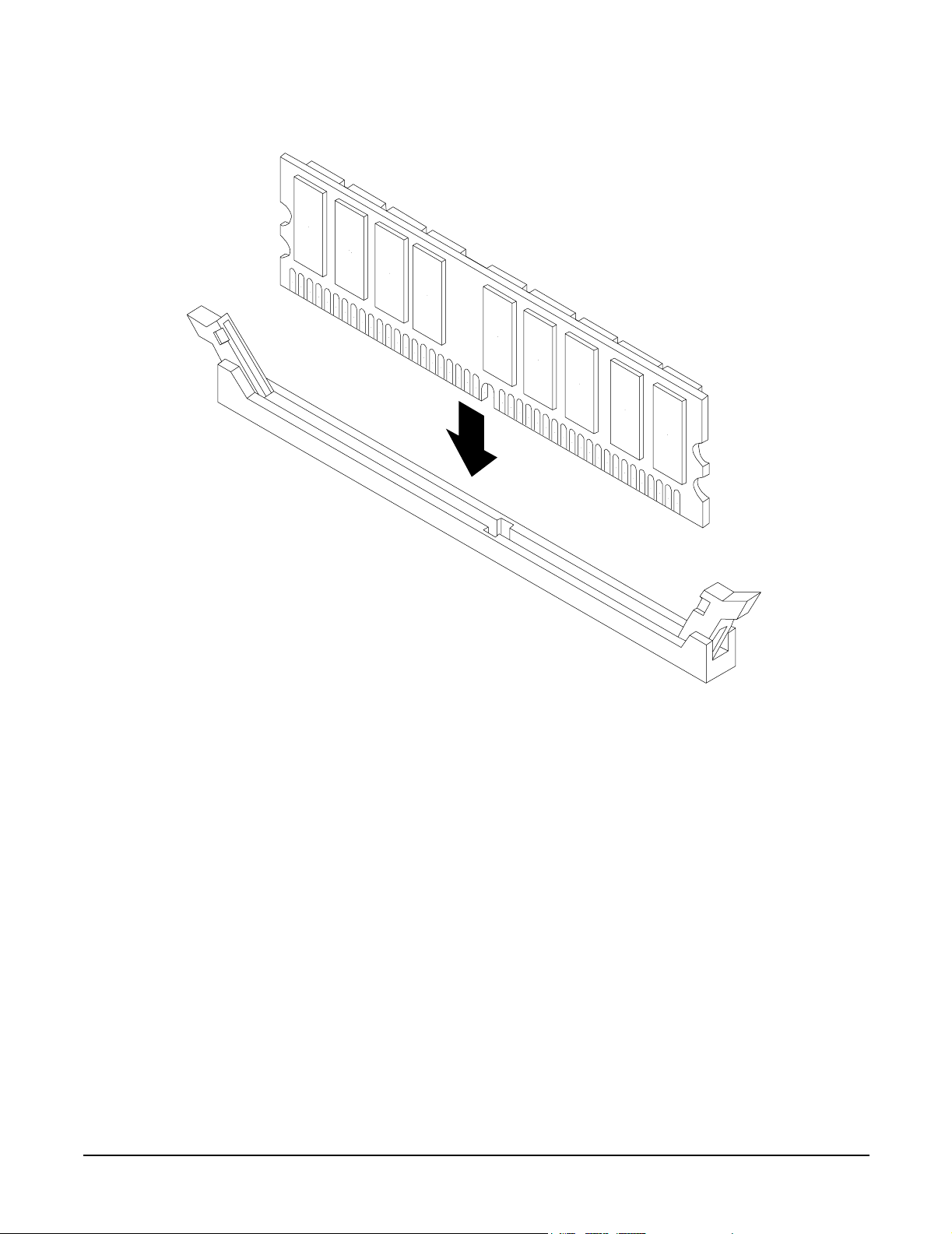
Step 7. Holding the DIMM by its edges, orient the DIMM such that the component side is facing the
processors, then insert the DIMM into the appropriate socket.
NOTE DIMM connectors are keyed so that they can be installed in only the correct
orientation.
Step 8. Gently and evenly push on each side of the DIMM until it seats in the socket. Observe that the
socket retainer clips return to the upright position when the DIMM is fully inserted.
Chapter 3
45
Page 46
Installing Additional Components
Installing Processors and Memory
Figure 3-22Inserting DIMM into a DIMM Socket
dimm_sokt
Step 9. Snap the socket retainer clips into place, ensuring that the DIMM is locked in the socket.
Step 10. Repeat steps 6 through 9 for each DIMM to be installed.
Step 11. Set the memory airflow guide in position and reinstall the top cover.
46
Chapter 3
Page 47

4 Troubleshooting
Introduction
This chapter presents troubleshooting information. Basic tips for start-up problems are presented, audio cues
and LED indicators are described and interpreted, and error messages (and how to retrieve them) are
described. In addition, problems that are associated with I/O functions and paths are discussed here.
Troubleshooting Methodology
WARNING Always disconnect the power cords and unplug telephone cables before removing
the server cover. Disconnect telephone cables to avoid exposure to shock hazard
from telephone ringing voltages. Disconnect the power cords to avoid exposure to
high energy levels that may cause burns when parts are short-circuited by metal
objects such as tools or jewelry.
CAUTION Do not operate the server for more than 2 minutes with any cover (including power supplies
and disk drives) removed. The covers also provide EMI containment and direct airflow within
the chassis. Depending on which cover or assembly is missing, the server may shutdown,
interrupting operations. In addition, damage to system components may result due to
overheating.
You can safely remove the front grill while the HP Server is running to remove and replace
hot-swap fans. The hot-swap power supplies and one hot-swap fan (accessible from the rear of
the chassis) can be replaced at any time. For any other service activity requiring access to
internal components, power down the server and observe all safety precautions.
The server was tested prior to shipping and should be in perfect working order. Failures encountered during
installation may be due to damage that occurred in transit. Reseating connectors may clear problems that
result from rough handling. If you are installing components or assemblies, compatibility problems or
incorrect installations may be the cause of problems. If you are installing components or assemblies, check
that items are correctly installed and that all connectors are fully engaged. If the unit will not power on,
check the power source before proceeding.
If a problem is encountered during initial operation, remove any add-in or optional components and retest the
server before continuing. Verify basic server operation before installing additional cards and configuring
software and hardware for your system requirements.
Troubleshooting is based on observation of server status indications and error messages, and by checking
system event logs. The system e-buzzer will provide an immediate indication of any start-up problems. LED
indicators can be observed on the front and rear of the server. Error messages are displayed on local and
remote consoles. System history (console, event, and history logs) are available through the management
processor, and can be accessed through the console. Additional information about troubleshooting can be
found in the hp Integrity cx2600 Operation and Maintenance Guide.
Chapter 4
47
Page 48

Troubleshooting
Troubleshooting Methodology
Offline troubleshooting programs are available on the resource CD that is shipped with your HP Server. To
troubleshoot your system you should be familiar with the Offline Diagnostics Environment (ODE) which runs
in the Extensible Firmware Interface (EFI). Descriptions and user information about offline troubleshooting
tools are available at http://docs.hp.com. The offline tools are available for downloading at
http://software.hp.com.
Using the Front Panel Power Button
The server power button on the front panel operates differently, depending on how long the button is held in
and on what the system is doing when the button is pressed. You must be aware of its uses to properly
troubleshoot the system.
If the server is off, and power is not connected to server power supplies, pressing the power button has no
effect.
If the server is off, and power is connected to server power supplies, the front panel power LED will blink at a
1-Hz rate. In this state, standby power is available to server circuits, but main power is off. Pressing and
holding the power button will accomplish the following:
• 1 – 3 seconds. System power turns on. The e-buzzer will beep if an error is encountered. (Refer to
“Troubleshooting Using Beep Codes (System e-buzzer)” on page 50 for a description of the e-buzzer.)
• 3 – 5 seconds. The e-buzzer will repeat the last stored error message (beep code).
If the server is on and the system is at the EFI, pressing and holding the power button will accomplish the
following:
• 1 – 3 seconds. System power turns off immediately (hard power down).
• 3 – 5 seconds. The e-buzzer will repeat the last stored error message (beep code).
• 5 seconds or longer. System power turns off immediately (hard power down).
If the server is on and the operating system is running, pressing and holding the power button will
accomplish the following:
• 1 – 3 seconds. System power turns off (software controlled power down).
• 3 – 5 seconds. The e-buzzer will repeat the last stored error message (beep code).
• 5 seconds or longer. System power turns off immediately (hard power down).
If the Server Will Not Power Up
Power problems during installation are usually related to the install process. If your server will not power up,
check the LED indicators on the power supply rear panels. Refer to “Rear Panel LEDs” on page 57 and
perform the following:
• If the DC In indicators are lit, it can be assumed that power is available to the server.
• If a fault indicator is lit, reseat the power supply. If the problem persists, remove and reseat boards within
the server. If the problem still persists, replace the power supply and/or the power supply interface board.
• If the DC Out indicators are lit, it can be assumed that power is supplied to the server circuits. If the
console shows that the server is powered up, but server LEDs indicate that power is off, remove and
reseat connectors on the LED status board. (If the problem still persists, replace the LED status board.) If
the console shows that the server is not powered up (server is off), remove and reseat connectors on the
system board. (If the problem still persists, replace the power supply interface board, the MP board, or the
system board.)
48
Chapter 4
Page 49

Troubleshooting
Troubleshooting Methodology
If EFI Is Not Available
If it is not possible to reach the EFI (from either the main disk partition or CD), then you must use the
following tools to help solve your problem:
• Front panel LEDs (page 52)
• Management processor (MP) (page 62)
— Console messages
— System event logs (SEL)
If the Operating System Will Not Boot
If your operating system will not boot, but you are able to reach the EFI (from either the main disk partition
or CD), then use the following tools to help solve your problem:
• Using the EFI shell, check the system logs and analyze any error messages. Refer to “Error Messages and
Event Logs” on page 58. Refer to Chapter 5 of this guide (Cable Connections) and to the hp Integrity
cx2600 Operation and Maintenance Guide for information about connecting a console and using the EFI
shell. (The hp Integrity cx2600 Operation and Maintenance Guide is included on the CD provided with
your system.)
• Offline Diagnostic Environment (ODE) (page 63)
• E-Diag Tools (page 64)
If the Operating System Will Boot
If your operating system is running and you are experiencing problems, use the following tools to help solve
your problem.
• Beep Codes (page 50)
• LEDs (page 51)
• Error Messages and event logs (page 58)
If Intermittent Server Problems Occur
Intermittent problems that occur during installation can usually be traced to power source problems, to a
loose connector, or to some other hardware problem. If you are experiencing intermittent problems, proceed as
follows:
• Check MP logs and analyze the problem. (Determine if there is more than one symptom and if the
problem is random.) Refer to “Management Processor (MP) Event Logs” on page 62.
• Verify that the DC power source is stable and within the –40 to –72 VDC range.
• Reseat all rear panel connectors.
• Reseat all hot-swappable fans and power supplies.
• Reseat all main memory DIMMs.
• Reseat all internal connectors (cable harness and board connectors).
Chapter 4
49
Page 50

Troubleshooting
Troubleshooting Using Beep Codes (System e-buzzer)
If DVD Problems Occur
DVD problems that occur during installation are usually related to faulty connections. If you are experiencing
DVD problems, proceed as follows:
• Remove and reinsert the disk.
• Replace the disk.
• Remove and reinstall the DVD drive. Check that connectors are fully engaged.
• Replace the DVD drive.
If Hard Drive Problems Occur
Hard drive problems that occur during installation are usually due to rough handling. The drive(s) may not
be correctly seated or may have been damaged in transit. If you are experiencing hard drive problems,
proceed as follows:
• Remove and reinsert the suspect hard drive(s).
• Swap the hard drive with one from another slot or with a known good spare.
• Remove and reinstall the hard drive backplane. Check that connectors are fully engaged.
• Replace the hard drive backplane.
If Console Problems Occur
Console problems during installations can be caused by faulty interconnections. If you are experiencing
monitor, keyboard, or mouse problems, proceed as follows:
• Check the monitor controls. Adjust contrast and brightness as required.
• Inspect all power and interconnecting cables. Check that all console connectors are fully engaged.
• Check that all MP board connectors are fully engaged.
• Exercise the appropriate self-test features of the console software.
Troubleshooting Using Beep Codes (System e-buzzer)
If a problem is detected when the system is booting, or when it is running, the system e-buzzer emits a series
of audible beeps that present an encoded error message. The e-buzzer emits a different number of beeps for
each type of error. If you do not hear the beeps, or may have miscounted beeps, you can repeat the message by
pressing the front panel power button for 3 to 5 seconds. (Release the power button when you first hear the
e-buzzer. Do not press the power button for more than 5 seconds).
The e-buzzer emits a modem-like sound that is repeated three times. Next, the e-buzzer emits a beep code
consisting of 0 to 7 beeps occurring at 1 second intervals. Each beep lasts 1 second. The e-buzzer does not
report all problems—only the error conditions described here. If the e-buzzer describes an error, check the
front panel LEDs and the system logs for additional information.
50
Chapter 4
Page 51

Troubleshooting
Troubleshooting Using LED Indicators
NOTE The error message and identifying information can be sent via telephone line to an authorized
help desk or to an HP Support facility. This telephone signal can be decoded to identify the
server by model and serial number, and to help identify the error. To send this signal to HP
Support via telephone, just hold the telephone next to the Locator button on the server front
panel while the system is booting.
The beep codes provide only general information. If you hear an error code, always check the LEDs and
system logs before replacing components. The LEDs and system error messages can help you identify the
failing item or assembly.
Tabl e 4-1 Beep Code Descrip tions
Number of
Beeps
1 Processor Processor absent or not correctly connected: Reseat or replace
2 Power Supply Power supply failure: Replace power supply.
3 Memory Memory failure: Check that matched DIMMs are correctly installed,
4 MP Card Management processor card malfunction: Reseat or replace the
5 PCI Card PCI I/O card malfunction: Reseat or replace the PCI card.
6 Critical System
Suspect
Component
Fai lur e
Description
processor.
replace DIMMs as appropriate.
Management processor card.
Two minutes have elapsed after BMC system startup and no
BOOT_START event has been logged into the System Event Log.
Possible causes include:
a. System clock failed
b. System board malfunction
c Bad CPU connection to mother board connection
d. CPU power pod malfunction
e. CPU malfunction
f. System firmware bad
7 System Board Defective system board: Contact HP Support for assistance.
Troubleshooting Using LED Indicators
Your hp Integrity cx2600 Server has LED indicators located on the front and rear of the server that you can
use to determine what repair action is required. (Additional LEDs within the server are described in the hp
Integrity cx2600 Operation and Maintenance Guide, which is included on the CD provided with your system.)
Descriptions of front and rear panel LEDs are provided in the following sections.
Chapter 4
51
Page 52

Troubleshooting
Troubleshooting Using LED Indicators
Front Panel LEDs
The front panel LEDs show you the system status at a glance. They include four diagnostic LEDs, and the
System, LAN, and power LEDs. The front panel LEDs are listed in the following tables, together with system
status and/or probable cause descriptions of likely system failures.
Figure 4-1 Front Panel LEDs
Locator
Button
chasfront
E-Buzzer
(behind panel)
Locator
LED
DVD/CD
Eject
Button
Diagnostic
LEDs 1-4
LAN4321 System
DVD/CD
Activity
LED
Table 4-2 Front Panel LED Definitions
LED/
Button
System
State
Flash Rate Color Description
LAN
LED
System
LED
Disk
Status
LED
Power
Button
Disk
Activity
LED
hp
integrity
cx2600
Power
LED
System LED Off Off Off System is off.
System LED Running Flashing at
Green System is booting or running EFI.
0.5 Hz
System LED Running Steady Green System normal—the operating system is up
and running.
System LED Warning Flashing at
1 Hz
Amber Attention required. Check the four diagnostic
LEDs and the MP Status log for information.
The LED will turn off when the MP log is
accessed.
System LED Fault Flashing at
2 Hz
Red Fault detected. Check the four diagnostic
LEDs and the MP Status log for information.
The LED can be turned off by the MP DC
command, or by correcting the problem.
52
Chapter 4
Page 53

Table 4-2 Front Panel LED Definitions (Continued)
Troubleshooting
Troubleshooting Using LED Indicators
LED/
Button
Diag LEDs
(1 thru 4)
LAN LED Off Off N/A The system is off (no power to LAN circuits) or
LAN LED Active Steady Green LAN link is established but LAN is inactive.
LAN LED Active Flashing at
Disk
Activity
LED
Disk
Activity
LED
Disk Status
LED
System
State
-- - Display system error condition (when System
Off Off Off Disk not active.
Active Flashing at
Off Off Off Pass through mode.
Flash Rate Color Description
LED is flashing yellow) or fault condition
(when System LED is flashing red). Refer to
Table 4-3 for error code information.
hardware failure.
Green LAN is active.
rate of LAN
activity
Green Disk is active.
rate of LAN
activity
Disk Status
LED
Disk Status
LED
CD Activity
LED
Locator
LED/Button
Power LED No power Off Off DC power not available to the server.
Power LED Standby
Power LED Main power onSteady Green Power is applied to all server circuits.
Off Steady Amber Drive fault.
Active Steady Green Drive operating normally.
Active Flashing at
rate of LAN
activity
(Flag) Flashing at
1 Hz
Flashing at
power
1 Hz
Green Disk is active.
Blue System locator LED may be remotely or
locally activated/deactivated to call attention
to a particular server.
Green DC power is connected to the server, but
power is off. Standby power (3.3V) is applied
to some server circuits.
Chapter 4
53
Page 54

Troubleshooting
Troubleshooting Using LED Indicators
Table 4-3 Diagnostic LED Displays and Meanings
Diag 1
LED
Off Off Green Red Flashing
Off Green Off Red Flashing
Off Green Green Red Flashing
Off Red Green Red Flashing
Off Red Red Off Flashing
Diag 2
LED
Diag 3
LED
Diag 4
LED
System
LED
Yellow
Yellow
Yellow
Yellow
Yellow
Description
Fan 3 warning. BMC is reporting that one fan
rotor is turning more slowly than expected (or
stopped). Investigate problem at the first
opportunity.
Fan 2 warning. BMC is reporting that one fan
rotor is turning more slowly than expected (or
stopped). Investigate problem at the first
opportunity.
Fan 5 warning. BMC is reporting that one fan
rotor is turning more slowly than expected (or
stopped). Investigate problem at the first
opportunity.
Power supply 2 warning. The power supply is
functioning but reporting an error condition.
Replace the power supply at the first
opportunity.
No video warning. No video output is available
from the management processor. Replace the
MP board.
Green Off Off Red Flashing
Yellow
Green Green Off Red Flashing
Yellow
Green Green Red Off Flashing
Yellow
Green Red Off Red Flashing
Yellow
Red Off Green Green Flashing
Yellow
Red Green Green Red Flashing
Yellow
Red Red Off Green Flashing
Yellow
Fan 1 warning. BMC is reporting that one fan
rotor is turning more slowly than expected (or
stopped). Investigate problem at the first
opportunity.
Fan 4 warning. BMC is reporting that one fan
rotor is turning more slowly than expected (or
stopped). Investigate problem at the first
opportunity.
System battery voltage low. Replace the system
battery.
Power supply 1 warning. The power supply is
functioning but reporting an error condition.
Replace the power supply at the first
opportunity.
Memory load order warning. Verify that DIMMs
are correctly installed.
Intake air temperature hot. Check for blockage.
Clean air intake openings.
CPU 1 temperature warning. Check for
blockages. Investigate the problem at the first
opportunity.
54
Chapter 4
Page 55

Troubleshooting Using LED Indicators
Table 4-3 Diagnostic LED Displays and Meanings (Continued)
Troubleshooting
Diag 1
LED
Red Red Green Off Flashing
Red Red Red Red Flashing
Off Off Green Red Flashing
Off Green Off Red Flashing
Off Green Green Red Flashing
Diag 2
LED
Diag 3
LED
Diag 4
LED
System
LED
Yellow
Yellow
Red
Red
Red
Description
CPU 0 temperature warning. Check for
blockages. Investigate the problem at the first
opportunity.
Undefined error condition (warning only). Check
the SEL for information.
Fan 3 failure. BMC is reporting that both fan
rotors are turning more slowly that expected (or
stopped). Replace the fan, fan control board, or
system board.
Fan 2 failure. BMC is reporting that both fan
rotors are turning more slowly that expected (or
stopped). Replace the fan, fan control board, or
system board.
Fan 5 failure. BMC is reporting that both fan
rotors are turning more slowly that expected (or
stopped). Replace the fan, fan control board, or
system board.
Off Green Red Off Flashing
Red
Off Red Off Off Flashing
Red
Off Red Off Red Flashing
Red
Off Red Green Red Flashing
Red
Green Off Off Red Flashing
Red
Green Off Green Red Flashing
Red
Green Off Red Off Flashing
Red
VRM overvoltage fault. Replace the system
board.
System firmware error. Power down the server,
wait 20 seconds and resume operation. If the
problem continues, replace the system board.
VRM power pod fault. Replace the system
board.
Power supply 2 fault. Replace power supply 2,
the power supply interface board, or the system
board.
Fan 1 failure. BMC is reporting that both fan
rotors are turning more slowly that expected (or
stopped). Replace the fan, fan control board, or
system board.
CPU 1 turbofan failure. Replace CPU 1, the
CPU power module, or the system board.
VRM undervoltage fault. Replace the system
board.
Chapter 4
55
Page 56

Troubleshooting
Troubleshooting Using LED Indicators
Table 4-3 Diagnostic LED Displays and Meanings (Continued)
Diag 1
LED
Green Green Off Red Flashing
Green Green Green Red Flashing
Green Red Off Red Flashing
Green Red Green Red Flashing
Red Off Off Green Flashing
Red Green Off Off Flashing
Diag 2
LED
Diag 3
LED
Diag 4
LED
System
LED
Red
Red
Red
Red
Red
Red
Description
Fan 4 failure. BMC is reporting that both fan
rotors are turning more slowly that expected (or
stopped). Replace the fan, fan control board, or
system board.
CPU 0 turbofan failure. Replace CPU 0, the
CPU power module, or the system board.
Power supply 1 fault. Replace power supply 1,
the power supply interface board, or the system
board.
12V range error. Something is loading the 12V
source. This can be either power supply, the
power supply interface, the system board, or any
using circuit. Replace items (1 at a time) to
identify the cause.
Memory bank error. Verify that DIMMs are
correctly installed.
Memory mismatch fault. DIMMs of different
size are installed in a single quad. Replace
DIMMs as required.
Red Green Green Off Flashing
Red
Red Green Green Green Flashing
Red
Red Green Green Red Flashing
Red
Red Green Red Off Flashing
Red
Red Green Red Green Flashing
Red
Red Red Off Green Flashing
Red
Red Red Green Off Flashing
Red
Red Red Green Green Flashing
Red
Memory access fault. Check error messages in
the SEL. Reseat or replace DIMMs as required.
Memory error detected. Check error messages in
the SEL. Reseat or replace DIMMs as required.
Intake air overtemperature fault. Check for
blockages. Replace the system board.
BMC firmware error. Power down the server,
wait 20 seconds and resume operation. If the
problem continues, replace the system board.
MP firmware error. Power down the server, wait
20 seconds and resume operation. If the problem
continues, replace the management processor.
CPU 1 overtemperature fault. Check for
blockages. Replace CPU 1 or the system board.
CPU 0 overtemperature fault. Check for
blockage. Replace CPU 0 or the system board.
Either or both CPUs not detected. Check CPU
installation and replace CPU, power module, or
system board if necessary.
56
Chapter 4
Page 57
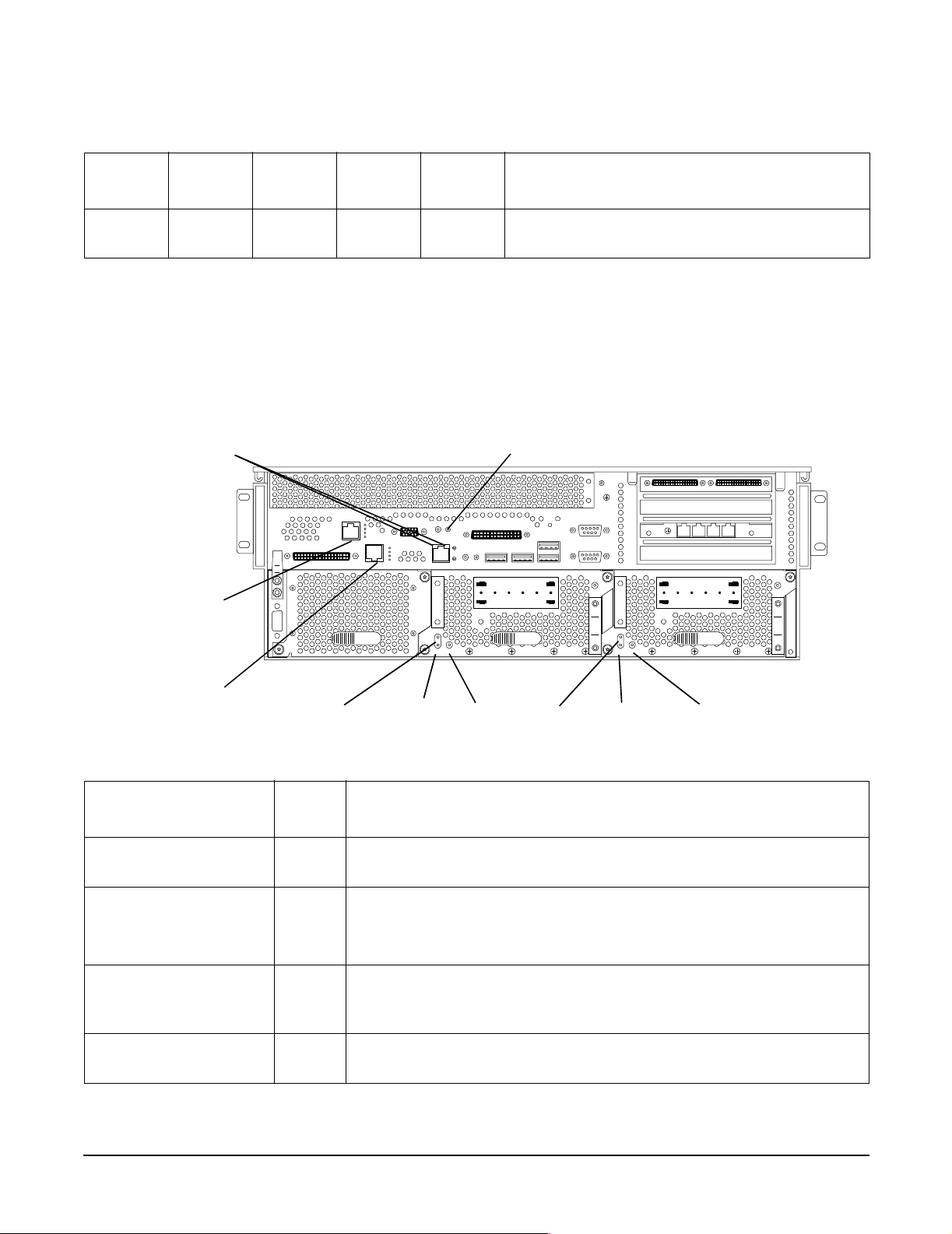
Troubleshooting Using LED Indicators
Table 4-3 Diagnostic LED Displays and Meanings (Continued)
Troubleshooting
Diag 1
LED
Red Red Red Red Flashing
Diag 2
LED
Diag 3
LED
Diag 4
LED
System
LED
Red
Description
Undefined error condition (catastrophic failure).
Check the SEL for information.
Rear Panel LEDs
The rear panel LEDs show you LAN and power supply status at a glance. The rear panel LEDs are listed in
the following table, together with descriptions of LAN and power status indications. Additional information
about these LEDs is provided in the hp Integrity cx2600 Operation and Maintenance Guide. (The hp Integrity
cx2600 Operation and Maintenance Guide is included on the CD provided with your system.)
Figure 4-2 Rear Panel LEDs
10/100 System
Management
LAN LEDs
Management
Processor
LAN LEDs
Gigabit
LAN
LEDs
Fault
DC Out DC In
rearview
Fault
DC InDC Out
Locator
Fault
Fault
DC Out DC In
DC InDC Out
Table 4-4 Rear Panel LED Definitions
LED/
Button
System Management
LAN Activity LED
System Management
LAN Speed LED
Locator Blue Lit by pressing the associated button, by pressing the corresponding
Power Supply Fault Amber Lit when a power supply failure has been detected. Indicates that
Chapter 4
Color Description
Green When lit, shows that port is linked.
Green When off (and Activity LED is lit), shows that port is linked to 10 Mb
LAN.
When lit, shows that port is linked to 100 Mb LAN.
button on the front panel, or by command from a remote location.
Identifies one server among many.
power supply has been cycled down or is not fully functional.
57
Page 58

Troubleshooting
Error Messages and Event Logs
Table 4-4 Rear Panel LED Definitions (Continued)
LED/
Button
Power Supply
DC Out
Power Supply
DC In
Gigabit LAN Gbit LED
(top)
Gigabit LAN 100 Mbit
LED (2nd from top)
Gigabit LAN Link LED
(2nd from bottom)
Gigabit LAN Activity
LED (bottom)
Management Processor
Self Test LED (top)
Management Processor
10BT LED (2nd from
top)
Color Description
Green Lit when a power supply is operating normally. Indicates that DC
power is being supplied to server circuits.
Green Lit when power (–36 to –72 VDC) is being supplied to the power
supply. Indicates that source power is available.
Green When off, no 1000 Mbps link has been detected.
When lit, port is linked at 1000 Mbps.
Green When off, no 100 Mbps link has been detected.
When lit, port is linked at 100 Mbps.
Green When off, no 10 Mbps link has been detected.
When lit, port is linked at 10 Mbps.
Green When off, no LAN activity has been detected.
When lit, port is linked at 1000 Mbps.
Green When off, self test is not active.
When lit, MP is running self test.
Green When off, no link detected or 100BT link is active.
When flashing, indicates 10BT LAN activity.
When lit steady, indicates that 10BT link has been established.
Management Processor
100BT LED (2nd from
bottom)
Management Processor
LAN Standby Power
LED (bottom)
Green When off, no link detected or 10BT link is active.
When flashing, indicates 100BT LAN activity.
When lit steady, indicates that 100BT link has been established.
Green When off, standby power is not applied to Management LAN circuits.
When lit, power is connected to the server but the server is not on.
Error Messages and Event Logs
Server firmware and management features monitor system operation, report errors, and log all significant
events. This section presents error message and log information. Refer to the hp Integrity cx2600 Operation
and Maintenance Guide for additional information and instructions to access error messages and logs.
58
Chapter 4
Page 59

Troubleshooting
Error Messages and Event Logs
EFI Error and Warning Messages
EFI error and warning messages are displayed on the console as part of the boot process. They can also be
retrieved using the EFI command: info warnings. Table 4-5 lists the error messages that may be
encountered during installation. Refer to the hp Integrity cx2600 Operation and Maintenance Guide for
additional information. It can be found on the HP Server Documentation CD-ROM which is provided with
your hp Integrity cx2600 Server.
Table 4-5 EFI Error and Warning Messages
Error
Number
2 Insufficient resources to assign to 1 or
more I/O devices
4 Unexpected hardware I/O configuration Incorrect I/O configuration. Contact the HP
7 No BMC installed in platform Update BMC firmware.
8 BMC cannot be accessed Check system logs for errors. Replace the
9 One or more BMC ports failed Communication with the BMC failed. Check
10 BMC system event log is full Clear the SEL.
11 Platform SCR is bad Contact the HP Support center for
12 Set time to BMC SEL failed Communication with the BMC failed.
13 SEL get info failed Communication with the BMC failed.
Message Description/Solution
Incorrect I/O configuration. Contact the HP
Support center for assistance.
Support center for assistance.
system board.
power. Replace the system board.
assistance.
Replace the system board.
Replace the system board.
14 Initial BMC SEL event failed —Communication with the BMC failed.
Replace the system board.
15 Update of BMC buffered data failed Communication with the BMC failed.
Replace the system board.
16 All ACPI BMC ports bad Communication with the BMC failed.
Replace the system board.
17 Read error on BMC token Communication with the BMC failed.
Replace the system board.
18 BMC token transmit checksum error Communication with the BMC failed.
Replace the system board.
19 Error writing BMC token on download Communication with the BMC failed.
Replace the system board.
20 NVM token access error Communication with the BMC failed.
Replace the system board.
Chapter 4
59
Page 60

Troubleshooting
Error Messages and Event Logs
Table 4-5 EFI Error and Warning Messages (Continued)
Error
Number
21 BMC token write error during NVM write
through
22 Error reading BMC token on upload to
NVM
23 Error reading BMC first boot token Communication with the BMC failed.
24 Primary FIT failed Reflash firmware.
25 Secondary FIT failed Reflash firmware.
26 PAL A warning. One copy of PAL is bad Reflash firmware.
27 PAL A warning. PAL is not compatible with
at least 1 CPU
28 Memory errors detected and PDT is
disabled
30 Memory required reinterleave to get a good
page 0
31 One or more ranks have chipspare disabled Information only, no action required.
Message Description/Solution
Communication with the BMC failed.
Replace the system board.
Communication with the BMC failed.
Replace the system board.
Replace the system board.
Update firmware.
Reseat DIMMs, if error persists replace bad
DIMMs.
Information only, no action required.
33 1 or more memory ranks are mismatched
or deallocated
34 Memory deallocated because of a loading
error
35 Memory load order error Check memory installation. DIMMs must be
36 The PDT is full Clear with pdt clear command in EFI shell.
37 At least one (1) CPU has bad fixed core
ratio
38 All CPUs were slated for compatibility
deconfig
39 Incompatible CPUs detected Check processor installation and match CPU
Check memory installation. Match DIMM
part numbers within each quad.
Check memory installation. DIMMs must be
installed with smallest capacity in the first
quad, an equal or larger capacity in the
second quad, and an equal or largest capacity
in the third quad.
installed with smallest capacity in the first
quad, an equal or larger capacity in the
second quad, and an equal or largest capacity
in the third quad.
Check processor installation. (Verify
installation and that identical processors
have been installed.)
Processor failure. Verify installation, then
replace processor. Contact the HP Support
center for assistance.
part numbers. CPUs must be identical.
60
Chapter 4
Page 61

Table 4-5 EFI Error and Warning Messages (Continued)
Troubleshooting
Error Messages and Event Logs
Error
Number
40 CPUs installed with mixed cache sizes Check processor installation and match CPU
40 CPUs installed with mixed cache sizes Check processor installation and match CPU
41 CPUs installed with mixed steppings Check processor installation and match CPU
42 All CPUs are over clocked Check processor installation and match CPU
43 At least one (1) CPU is over clocked Check processor installation and match CPU
44 Monarch changed to lowest stepping CPU Information only. If the message is repeated,
46 CPUs loaded in wrong order Reload processors in correct order.
48 SAL NVM cleared Information only, no action required.
49 EFI NVM cleared Information only, no action required.
50 EFI NVM failed Reboot the server. If the error message is
Message Description/Solution
part numbers. CPUs must be identical.
part numbers. CPUs must be identical.
part numbers. CPUs must be identical.
part numbers. CPUs must be identical.
part numbers. CPUs must be identical.
contact the HP Support center for assistance.
repeated, contact the HP Support center for
assistance.
51 CPU deconfigured by SAL_B Check processor installation. (Verify
installation.) Replace processor that was
deconfigured.
52 A ROM revision is inconsistent with FIT or
REVBLOCK
53 Error building S MBIOS Contact the HP Support center for
54 Failure constructing the EFI Memory Data
Table (MDT)
55 UUID error Update with sysset command.
56 Error reading CPU S MBUS information
ROM
57 Error accessing FRU information Replace the FRU which was reported. If the
58 Checksum error accessing FRU
information
One or more firmware components (fw, bmc,
mp) is out of date.
assistance.
Contact the HP Support center for
assistance.
Reboot the server. If the error message is
repeated, replace the failing processor.
error message is repeated, contact the HP
Support center for assistance.
Replace the FRU which was reported. If the
error message is repeated, contact the HP
Support center for assistance.
Chapter 4
61
Page 62

Troubleshooting
Error Messages and Event Logs
Table 4-5 EFI Error and Warning Messages (Continued)
Error
Number
59 FRU information version error Replace the FRU which was reported. If the
Message Description/Solution
error message is repeated, contact the HP
Support center for assistance.
Event Logs
The System Event Log (SEL) and Forward Progress Log (FPL), Live Event Log, and Boot logs are available
via the MP. The SEL records system events that are of major importance to system operations. All entries for
the SEL are forwarded to the FPL. The FPL contains system events, forward progress messages from the
BMC, and status/error messages from system firmware, EFI, and from the operating system. The Live Event
and Boot Logs record operating events as they occur.
You can view these logs using the MP. Only basic information is provided here. For complete information,
refer to the hp Integrity cx2600 Operation and Maintenance Guide. It can be found on the HP Server
Documentation CD-ROM which is provided with your hp Integrity cx2600 Server.
Management Processor (MP) Event Logs
The MP interface provides diagnostic and configuration capabilities. To access your MP interface, perform the
following steps:
NOTE The MP interface must be accessed from a terminal console which is attached to the MP via the
MP LAN or MP remote serial connector. Refer to the hp Integrity cx2600 Operation and
Maintenance Guide for additional information.
Step 1. If necessary, press
Step 2. Log in with proper username and password.
Step 3. Press
Step 4. Press
Step 5. Select the desired log for viewing. (For a complete explanation of the management processor and all
cl to display the console logs. This log displays console history from oldest to newest.
sl to display the system logs. The system logs consist of:
•System event
• Forward progress
• Current boot
• Previous boot
• Live events
• Clear SEL/FPL logs
commands see the hp Integrity cx2600 Operation and Maintenance Guide.)
Ctrl+B to access the MP interface.
62
Chapter 4
Page 63
Troubleshooting
Troubleshooting Using Offline Support Tools
Disk and I/O Path Logging
Some failures result in I/O path logging. These paths help to indicate the source of the error and may be
included in the error message or logged into console or event logs. The following table describes the disk drive
and PCI slot paths for your HP Server.
Table 4-6 Disk and DVD Paths
Slot Path
Slot 0 Acpi(HWP0002,100)/Pci(1|0)/Scsi(Pun0,Lun0)
Slot 1 Acpi(HWP0002,100)/Pci(1|0))/Scsi(Pun1,Lun0)
Slot 2 Acpi(HWP0002,100)/Pci(1|1))/Scsi(Pun2,Lun0)
DVD Acpi(HWP0002,0)/Pci(2|0))/Ata(Primary,Master)
Tabl e 4-7 I/O Pat hs
I/O Slot Path
PCI Slot 1 Acpi(HWP0002,400)/Pci(1|0)
PCI Slot 2 Acpi(HWP0002,300)/Pci(1|0)
PCI Slot 3 Acpi(HWP0002,200)/Pci(1|0)
PCI Slot 4 Acpi(HWP0002,600)/Pci(1|0)
Troubleshooting Using Offline Support Tools
You can use offline support tools to troubleshoot your hp Integrity cx2600 Server.
• Offline Diagnostic Environment (ODE)—available on IPF Offline Diagnostics on the resource CD that
comes with your HP Server.
• E-DiagTools—available from IPF Offline Diagnostics on the resource CD that comes with your server.
• Management Processor (MP) event logs—available by logging on to the management processor via the
MP LAN or MP remote serial connectors.
Offline Diagnostic Environment (ODE)
ODE is used to evaluate specific hardware components via a command line interface. To access ODE from the
IPF Offline Diagnostics CD, perform the following steps:
Step 1. Power on your HP Server and insert the IPF Offline Diagnostics CD into the DVD-ROM tray.
Step 2. Do not permit the server to boot into an operating system and at the EFI Boot Manager, select EFI
shell.
Step 3. Determine the file system that represents the CD and enter the appropriate command to access the
CD.
Chapter 4
63
Page 64

Troubleshooting
Troubleshooting Using Offline Support Tools
E-Diag Tools
E-DiagTools is used to evaluate the hardware integrity of your HP Server. To access E-DiagTools from the IPF
Offline Diagnostic CD, perform the following steps:
Step 1. Power on your HP Server and insert the IPF Offline Diagnostics CD into the DVD-ROM tray.
Step 2. Do not permit the server to boot into an operating system and at the EFI Boot Manager, select EFI
shell.
Step 3. Determine the file system that represents the CD and enter the appropriate command to access the
CD.
Step 4. After accessing the CD diagnostic menu, launch e-Diagtools for IPF and run the Basic and
Advanced tests according to the menus.
Figure 4-3 Offline Diagnostic Main Menu
***************************************************************************
****** ******
****** Offline Diagnostic Environment ******
****** ******
****** (C) Copyright Hewlett-Packard Co 1993-2003 ******
****** All Rights Reserved ******
****** ******
****** HP shall not be liable for any damages resulting from the ******
****** use of this program. ******
****** ******
****** TC Version B.00.10 ******
****** SysLib Version B.00.06 ******
****** Mapfile Version B.01.05 ******
****** ******
***************************************************************************
Type HELP for command information.
ODE> ls
Modules on this boot media are:
filename type size created description
-----------------------------------------------------------------------------
CIODIAG2.EFI TM 642560 06/06/2003 Core IO diagnostic
CPUDIAG.EFI TM 737280 06/06/2003 Processor diagnostic
IODIAG.EFI TM 143872 06/06/2003 Runs selftests on I/O modules
MAPPER.EFI TM 1653248 06/06/2003 System mapping utility
MEMDIAG.EFI TM 263168 06/06/2003 Memory diagnostic
PERFVER.EFI TM 814592 06/06/2003 Runs ROM-based selftests on peripherals
PLUTODIAG.EFI TM 514560 06/06/2003 SBA/LBA diagnostic
COPYUTIL.EFI TM 1041920 06/06/2003 Disk-to-tape copy utility
DFDUTIL.EFI TM 850432 06/06/2003 Disk firmware download utility
FCFUPDATE.EFI TM 608256 06/06/2003 FW Update Utility for Fibre Channel
ODE>
Other Event Logs and General Diagnostic Tools
This section describes other general diagnostic tools that will be provided for your HP Server and how to
generate other event logs for troubleshooting diagnosis.
• A general diagnostic tool that is available to support your HP Server is the MCA analyzer
• Event logs not generated by the management processor include:
— Machine check abort log (MCA)
— Corrected machine check log (CMC)
— Corrected platform error log (CPE)
64
Chapter 4
Page 65

Troubleshooting
Troubleshooting Using Offline Support Tools
To access these logs type in at the shell>command line prompt:
errdump mca
errdump cmc
errdump cpe
Hypothetical Troubleshooting Scenario
The following describes a hypothetical troubleshooting scenario that might occur with your hp Integrity
cx2600 Server.
1. This is the entry point to the troubleshooting process. Here, you pick from a set of symptoms, ranging
from very simple (system LED is blinking) to the most difficult (MCA has occurred). The following is a list
of symptom examples:
• System LED blinking
• System will not power up
• System will not boot
• Machine check abort (MCA) occurred
2. This step narrows down the observed problem to the specific troubleshooting procedure required. Here,
you isolate the failure to a specific part of the machine so that you can perform more detailed
troubleshooting. For example:
• Problem—System LED blinking yellow or red
— If the LED corresponds to a system alert message on the control console, analyze recent errors
logged by the management processor.
— If the diagnostic LEDs identify a probable cause, analyze the logged error messages for additional
information.
3. At this point you will probably know which component of your HP Server needs attention. For example, if
the symptom was “System won’t power up” the initial troubleshooting procedure may have led to a
problem with the power supplies.
4. You have now reached the point where the failed Field Replaceable Unit (FRU or FRUs) have been
identified and need to be replaced. You must now perform the specific remove and replace and verification
steps. See the hp Integrity cx2600, Operation and Maintenance Guide on the documentation CD included
with your system for remove and replace procedures on all FRUs in your HP Server.
NOTE If multiple FRUs are identified as part of the solution, a fix may not be complete unless all
identified failed FRUs are replaced.
5. There may be specific recovery procedures you need to perform to finish the repair. For example, if the
management processor is replaced, you will need to restore customer-specific information such as user
profiles, network IDs, and passwords. See the hp Integrity cx2600, Operation and Maintenance Guide on
the documentation CD included with your system for procedures on setting up your management
processor.
Chapter 4
65
Page 66

Troubleshooting
Troubleshooting Using Offline Support Tools
66
Chapter 4
Page 67

5 Cable Connections
Input Power
The hp Integrity cx2600 server comes with two power supplies installed: each powered from its own power
cable. The input for each connector is rated for –48 VDC (–40 to –72 VDC) at up to 15 amps (max.). (See
Figure 5-2 for power supply terminals/connections.) The server will function normally with only one power
supply installed, but N+1 redundancy requires that both power supplies be used during normal operations.
Under normal operating conditions, the two power supplies share the load.
Figure 5-1 hp Integrity cx2600 Power Supply (rear view)
+
–
++––
Fault
DC Out DC In
psrearpnl2
WARNING Voltages and hazardous energy can be present at various locations within the server
whenever a power source is connected. This hazard is present even when the power
switch is in the off position. Failure to observe this warning could result in personal
injury or damage to equipment.
Chapter 5
67
Page 68

Cable Connections
Wire Selection and Terminal Lugs for Connection of DC Power
Wire Selection and Terminal Lugs for Connection of DC Power
WARNING Always check that the power cable is not connected to a power source before
attempting to connect the power cable to server power supply terminals. Failure to
observe this warning could result in personal injury or damage to equipment.
WARNING Failure to use the appropriate wire and terminal lugs when connecting DC power to
the server could result in personal injury or damage to equipment.
A DC power terminal block is provided at the rear of each DC power supply. All four terminals (2+ and 2-)
should be used. HP recommends a minimum #12 AWG or larger copper conductor be used for connecting DC
power. The wire style and insulation type must be appropriately rated for the application.
Aluminum conductors should be avoided. Aluminum has a coefficient of expansion that differs significantly
from that of other metals commonly used in power hardware. Because of this difference, use of aluminum
conductors can cause connector hardware to loosen, overheat, and fail.
The terminal lugs used to connect DC power must be rated to handle the expected load of 15A/PSU. The width
of the lug can be no larger than 0.3 inches (0.762 cm).
68
Chapter 5
Page 69

Cable Connections
Core I/O Connections
Core I/O Connections
The locations of interface connectors on the hp Integrity cx2600 Server rear panel are shown in Figure 5-2.
Each hp Integrity cx2600 server core I/O includes:
Figure 5-2 hp Integrity cx2600 Server (rear view)
MP Reset
Switch
MP LAN
LVD/ SE
SCSI
MP
VGA
rearview
Gigabit
Ethernet
LAN
• One USB Keyboard connector
Locator Button
Fault
DC Out DC In
10/100 System
Management
LAN
and LED
TOC
Button
Console/
Remote/
UPS
Keyboard
USB Port
Serial Port A/
Console
Fault
DC Out DC In
Mouse
USB Port
Serial Port B
USB Port
• One USB Mouse connector
•Two USB ports
• Two serial ports (A and B)
• One tri-port serial connector (Console, Remote, and UPS) for connection breakout cable
• VGA controller connector
• One System Management (10/100) LAN -RJ45
• One 10/100 LAN-RJ45
•One 1 Gb LAN-RJ45
• One Management Processor (MP) LAN -RJ45
• SCSI LVD/SE connector.
• Four PCI Connections (0 to 4 PCI cards may be used)
Chapter 5
69
Page 70

Cable Connections
Core I/O Connections
Management Processor (MP)
The management processor is an independent support system for the server. It provides a way for you to
connect to a server and perform administration or monitoring tasks for the server hardware.
The management processor controls power, reset, transfer of control (TOC) capabilities, provides console
access, displays and records system events, and can display detailed information about the various internal
subsystems. The management processor also provides a virtual front panel which can be used to monitor the
front panel LEDs from a remote location.
The management processor is available whenever the system is connected to a power source, even if the hp
Integrity cx2600 server main power switch is in the off position.
Access to the management processor can be restricted by user accounts. User accounts can be password
protected and provide a specific level of access to the server and management processor commands.
Multiple users can interact with the management processor. Users can select any of the following options
from the MP Main Menu: enter management processor command mode, enter console, view event logs, view
console history, display virtual front panel, enter console session, or connect to another management
processor. Multiple users can select different options from the MP Main Menu at the same time. However,
management processor command mode and console mode are mirrored. The MP allows only one user at a
time to have write access to the shared console.
Accessing the Management Processor
You can connect a console to the management processor using either of the following methods:
• Local access-connect a terminal to the rear panel console/remote/UPS port using a breakout cable.
• Network access-connect via web console or telnet to the management processor LAN port, if login access
through the management processor LAN is enabled.
Local Terminal Access to the Management Processor
Communication with the management processor can be established by connecting a terminal to the local MP
I/O serial port (Console/Remote/UPS connector) on the server rear panel. Install the M (breakout) cable and
connect the terminal to the console connector of the M cable.
A terminal session may be established using a standalone terminal, or using terminal emulation software
such as Reflection 1 running on a PC. Install the breakout (M) cable (connect to the Console/Remote/UPS
connector) and connect the terminal to the Console connector.
During installation, communicating with the management processor enables such tasks as:
• Verifying that the components are present and installed correctly
• Setting the LAN IP addresses
Setting Terminal Parameters
After powering on the terminal, ensure the communications settings are as follows:
•8/none (parity)
• 9600 baud
• None (receive)
•None (transmit)
70
Chapter 5
Page 71

Cable Connections
Core I/O Connections
If the terminal is a PC using Reflection 1, check or change these communications settings by performing the
following steps:
Step 1. From the Reflection 1 Main screen, pull down the Connection menu and select Connection
Setup.
Step 2. Select Serial Port.
Step 3. Select Com1.
Step 4. Check the settings and change, if required.
Go to More Settings to set Xon/Xoff. Click OK to close the More Settings window.
Step 5. Click OK to close the Connection Setup window.
Step 6. Pull down the Setup menu and select Terminal (under the Emulation tab).
Step 7. Select a supported terminal type.
The preferred type is VT100.
Step 8. Click Apply.
This option is not highlighted if the terminal type you want is already selected.
Step 9. Click OK.
Network Access to the Management Processor
By connecting the management processor LAN port to an active network, another host on the same subnet
can set the management processor IP address via the ping command. After the IP address has been set, a
telnet session can be established to configure additional parameters.
To configure the management processor LAN IP address, perform the following steps:
Step 1. Determine the Medium Access Control (MAC) address of the management processor LAN interface
by viewing the label located at the rear of the server.
Step 2. Connect a LAN cable on your local subnet to the MP LAN port.
Step 3. Add an Address Resolution Protocol (ARP) table entry to another host located on your local subnet.
This ARP table entry will map the MAC address of the core I/O LAN interface to the IP address
chosen for that interface.
NOTE Adding an entry to the ARP table is typically done using the ARP command with the
appropriate option. For example, arp -s is used with Windows. Consult your
operating system documentation for more information.
Step 4. Use the ping command from the host that has the new ARP table entry. The destination address is
the IP address that is mapped to the MAC address of the management processor. The management
processor LAN port should now be configured with the appropriate IP address.
Step 5. Use the telnet command to connect to the management processor from a host on the local subnet.
Interacting with the Management Processor
To interact with the management processor, perform the following steps:
Chapter 5
71
Page 72

Cable Connections
Core I/O Connections
NOTE On initial system installation, the MP has two default user accounts. They are:
1. Administrator level user; login=Admin, password=Admin (both are case sensitive).
2. Operator level user; login=Oper, password=Oper (both are case sensitive).
For security reasons, it is recommended that the UC command be used during the initial logon
session (enter CM at the MP prompt, and enter UC at the MP:CM> prompt) to modify default
passwords or to delete and create user accounts.
Step 1. Log in using your management processor user account name and password.
NOTE The management processor will start with the MP Main Menu displayed. To follow
these steps, make sure you are at the Main Menu. If you are not at the Main Menu,
use Ctrl+B to return to the Main Menu.
Step 2. Use the management processor menus and commands as needed. Main Menu commands are shown
in Table 5-1, “Management Processor Commands and Descriptions.” Commands not displayed in
the MP Main Menu can be accessed in command mode by first using the
CM command at the MP
prompt. A list of available commands is presented in and can be displayed by using the
management processor help function (enter
the MP Main Menu by typing
Ctrl+B.
HE followed by LI at the MP>prompt). You can return to
Step 3. Log out using the X command (enter
X at the MP> prompt) after returning to the MP Main Menu.
The MP Main Menu
Main menu commands:
MP MAIN MENU:
CO: Console
VFP: Virtual Front Panel
CM: Command Menu
CL: Console Logs
SL: Show Event Logs
HE: Main Menu Help
X: Exit Connection
Configuring Management Processor LAN Information
LAN information includes the management processor network name, the management processor IP address,
the management processor subnet mask, the management processor gateway address, and the web console
port number.
To set the management processor LAN IP address:
Step 1. At the MP Main Menu prompt (MP>), enter CM to select command mode.
Step 2. At the command mode prompt (MP:CM>), enter LC (for LAN configuration).
The screen displays the default values and asks if you want to modify them. It is good practice to
write down the information, as it may be required for future troubleshooting. See “The LC
Command Screen”.
72
Chapter 5
Page 73

Cable Connections
Core I/O Connections
NOTE The value in the “IP address” field is set at the factory. The customer must provide
the actual management processor LAN IP address.
Step 3. The current lc data is displayed. When prompted to enter a parameter name, A to modify All, or
Q to Quit, enter A to select all parameters.
Step 4. The current IP address is displayed. When prompted to enter a new value or Q, enter the new IP
address.
Step 5. The current host name is displayed. When prompted to enter a new value or Q, enter the new
management processor network name.
This is the host name for the management processor LAN. The name can be up to 64 characters in
length, and can include dashes, underlines, periods and spaces.
Step 6. The current subnet mask name is displayed. When prompted to enter a new value or Q, enter the
new subnet mask name.
Step 7. The current gateway address is displayed. When prompted to enter a new value or Q, enter new the
gateway address.
Step 8. The current web console port number is displayed. When prompted to enter a new value or Q, just
hit
enter. The message -> Current Web Console Port Number has been retained will be
displayed.
Step 9. The current link state information is displayed. When prompted to enter a new value or Q, just
press
enter. The message -> Current Link State has been retained will be displayed.
Step 10. A new lc listing is displayed, including the values entered in the preceding steps. Verify that the
desired values have been accepted. When prompted to enter a parameter for revision, Y to confirm,
or Q to Quit, enter Y to confirm all parameters.
Step 11. Observe the following display:
> LAN Configuration has been updated
-> Reset MP (XD command option ‘R’) for configuration to take effect.
MP Host Name: name (the name entered in step 5)
MP:CM>
Step 12. Enter XD -reset to reset the MP.
Step 13. After the MP resets, log into the MP again. Then enter the MP command mode (enter CM at the MP:
prompt).
Step 14. At the MP:CM> prompt, enter LS to confirm the new LAN settings.
Step 15. Enter SA to enable/disable web console and telnet access after the MP has been reset.
Chapter 5
73
Page 74

Cable Connections
Core I/O Connections
The LC Command Screen
LC commands:
MP:CM> lc -ip 127.0.0.1 -host uninitialized -subnet 255.255.255.0 -gate 127.0.0.1 -web 2003
New LAN Configuration (* modified value):
* IP Address: 127.0.0.1
* MP Host Name: uninitialized
* Subnet Mask: 255.255.255.0
* Gateway Address: 127.0.0.1
Link State: Auto Negotiate
* Web Console Port Number: 2023
Confirm? (Y/ {N}) : y
-> LAN configuration has been updated
-> Reset the MP (XD command option ‘R’ ) for confirmation to take effect.
MP Host Name : uninitialized
MP:CM> xd -reset
74
Chapter 5
Page 75

Management Processor Commands
Table 5-1 Management Processor Commands and Descriptions
Command Description
BP Reset BMC passwords
CA Configure serial port parameters
CE Log a repair in the history buffer
CL Display console history
CG Certificate generator
CM Enter command mode
CO Return to redirected console mode
CSP Connect to another service processor
DATE Display date
Cable Connections
Core I/O Connections
DC Default configuration
DF Display FRUID
DI Disconnect remote or LAN console
FW MP firmware upgrade
HE Display help for menu or command
ID System information
IT Modify MP inactivity timers
LC LAN configuration
LS LAN status
MA Return to MP Main Menu
MR Modem reset
MS Modem status
PC Remote power control
PG Configure paging
PR Power restore policy configuration
PS Power management module status
RB Reset BMC through toggle GPIO pin
RS Request BMC to reset system through RST signal
SA Configure remote/modem-LAN telnet and web access options
SE Activate a system session on locator remote port
Chapter 5
75
Page 76

Cable Connections
Booting the Server
Table 5-1 Management Processor Commands and Descriptions (Continued)
Command Description
SL Show logs
SO Security options and access control
SYSREV Display all firmware revisions
SS System status of processor modules
TC Transfer of control-system reset through INIT signal
TE Tell-send a message to other users
UC User configuration
VFP Virtual front panel
WHO Display connected management processor users
X Exit from MP Main Menu
XD MP diagnostics and/or reset
Booting the Server
To boot the server, press the power switch located on the front panel.
If the autoboot function is enabled, the system will boot to the installed operating system. If autoboot is not
enabled, the system will enter the EFI boot manager. The EFI boot manager allows you to control the server’s
booting environment. For more information about the EFI boot manager, review the Utilities chapter of the
Operations and Maintenance Guide.
76
Chapter 5
Page 77

Index
A
Accessing a rack mounted server
aluminum conductors, DC power, 68
antistatic wrist strap, 15
B
Booting
HP Server
C
Console problems occur
Core I/O
connections
Covers
top, removing
D
DIMMs
installing
removing, 42
Disk drives
installing, 19
removing, 18
Disk drives, Hot-Plug
installing
DVD problems occur, 50
E
E-Diag Tools
EFI error and warning messages, 59
EFI Is not available, 49
Event logs, 62
CMC, 64
CPE, 64
Management processor, 62
MCA, 64
F
Fans, removing and replacing
front fans
rear fans, 29
G
Grill
removing
replacing, 24
Ground lug, 17
H
Hard drive problems occur
Hot Plug
disk drives
Hot Swap
chassis fans, remove and replace
power supplies, 18
Hot-swapping components
front fans
power supplies, 20
, 76
, 50
, 69
, 25
, 44
, 18, 19
, 64
, 28
, 24
, 18, 19
, 28
, 15
, 50
, 20, 27
rear fan, 29
Hypothetical troubleshooting scenario, 65
I
I/O baseboard
I/O, core, 69
Input power, 67
Installing components
disk drives
front grill, 24
memory, 42
PCI card cage, 31
PCI cards, 31
rear fan, 29
top cover, 25
Intermittent Server Problems, 49
IP address
default
L
LEDs, front panel
LEDs, rear panel, 57
Logs, 64
M
Management processor
accessing
configuring for LAN, 72
description, 70
network access, 71
terminal access to, 70
Memory
installing DIMMs
removing DIMMs, 42
supported DIMMs, 42
O
Offline Diagnostic Environment, ODE
Operating System
will boot or will not boot
P
PCI Card
installing
removing fan, 31
PCI card cage
installing, 31
removing fan, 31
Power button, 48
Power connection, 67
Power problems, 48
Power supplies
rear view
removing and replacing, 67
terminals, 23
Processor
installing
removing fan, 36
, 31, 34
, 19
, 72
, 52
, 70
, 42
, 63
, 49
, 31
, 21
, 40
77
Page 78

Index
R
Rack
installing into
Rack Mounted, accessing, 15
Reflection 1, 71
Removing components
disk drives
front fans, 28
front grill, 24
memory, 36
PCI card cage, 31
PCI cards, 31
power supplies, 20
processors, 36
rear fan, 29
top cover, 25
T
terminal lug, DC power
Tools, 15
Top cover
removing, 25
replacing, 26
Troubleshooting
beep codes
console problems occur, 50
DVD problems occur, 50
error messages, 58
front panel LEDs, 52
hard drive problems occur, 50
methodology, 47
offline support tools, 63
operating system, 49
rear panel LEDs, 57
, 13
, 18
, 68
, 50
U
Unpacking the server
W
wire selection, DC power
, 13
, 68
78
 Loading...