

Page 1

Terminal Emulation
User's Guide
Page 2

Trademarks
ADDS Viewpoint A2 is a trademark of Applied Digital Data Systems Inc.
AIX is a registered trademark of International Business Machines Corporation.
DEC, VT52, VT100, VT131, VT220, VT300, VT320, VT340, VT400 and VT420 are
registered trademarks of Digital Equipment Corporation.
Hazeltine is a trademark of Esprit Systems, Inc.
IBM is a registered trademark of International Business Machines Corporation.
Microsoft is a registered trademark of Microsoft Corporation.
TeleVideo is a registered trademark, and TeleVideo 910, 910+ and 925 are trademarks
of TeleVideo Systems, Inc.
WYSE is a registered trademark, and WY-50, WY-50+ and WY-60 are trademarks of
Wyse Technology Inc.
All other product names are trademarks of their respective manufacturers.
Copyright © 2003 by Pericom Software PLC. All rights reserved.
Before reproduction of this material in part or in whole, obtain written
consent from Pericom Software PLC.
Pericom Software PLC, The Stables, Cosgrove, Milton Keynes, MK19 7JJ, UK
Tel: +44 (0) 1908 267111 Fax: +44 (0) 1908 267112
Page 3

Contents
Contents
Introduction....................................................... 1-1
About This User's Guide ............................................................... 1-1
Terms & Conventions.................................................................... 1-2
Getting Started.................................................. 2-1
WBT Session Configuration .......................................................... 2-1
Using The Connection Wizard .......................................................... 2-1
Terminal Emulation Configuration ................................................... 2-6
Emulation Options ...................................................................... 2-6
DEC Suite Options ..................................................................... 2-7
HP 700-92/96 Option..................................................................2-8
IBM 3151 Option........................................................................2-8
IBM 3270 Options ...................................................................... 2-8
IBM 5250 Options ...................................................................... 2-8
TCP/IP Connection Settings ........................................................... 2-10
TN3270 Options .......................................................................2-12
TN5250 Options .......................................................................2-14
5250 Printer Options.................................................................2-16
Serial Connection Settings ..............................................................2-19
Automate Login Process ................................................................. 2-21
Printer Port Settings ......................................................................... 2-23
GUI Overrides .................................................................................2-25
Aux Port Settings.............................................................................2-26
Emulator Window Features ........................................................ 2-27
The Menu Bar.................................................................................. 2-27
The Toolbar ..................................................................................... 2-28
The Soft Buttons..............................................................................2-28
The Status Bar ................................................................................. 2-28
Hotspots ...........................................................................................2-30
Contents-1
Page 4

Contents
Keyboar d Configuration ................................... 3-1
Keyboard Mapping........................................................................ 3-1
Defining Key Functions................................................................. 3-1
Defining A Key Or Key Combination .............................................. 3-2
Entering Control Characters .............................................................. 3-3
Key Combinations & Sequences ....................................................... 3-3
Compose Character Sequences ..................................................... 3-4
Mouse Functions .............................................. 4-1
Introduction ................................................................................... 4-1
Redefining Mouse Functions ......................................................... 4-1
Selecting & Copying Text.............................................................. 4-2
Moving The Cursor In Block Mode............................................... 4-2
Send Keyword................................................................................ 4-3
Show & Action Hotspots ............................................................... 4-3
Emulating Middle Mouse Button .................................................. 4-3
The Toolbar........................................................ 5-1
Using The Toolbar ........................................................................ 5-1
The Predefined Button Tools......................................................... 5-1
Redefining The Toolbar................................................................. 5-3
Adding Button Bitmaps.....................................................................5-3
Assigning Functions To Buttons ....................................................... 5- 4
Removing Button Tools .................................................................... 5-5
Saving The Button Tools .................................................................. 5-5
Setup Menus ..................................................... 6-1
Displaying & Closing Menus ........................................................ 6-1
Using The Menus........................................................................... 6-2
Dialog Boxes ................................................................................. 6-3
Default Settings ............................................................................. 6-4
Specifying Characters In Setup Entries ........................................ 6-4
Creating A Connection Template.................................................. 6-5
Selecting A Connection Template ....................................................6-6
Menu Descriptions ........................................................................ 6-7
Contents-2
Page 5

Contents
File Menu...........................................................................................6-7
Edit Menu ........................................................................................ 6-14
Settings Menu .................................................................................. 6-15
Emulation Settings .......................................................................... 6-17
HP 700-92/96 Settings ..................................................................... 6-20
IBM 3151 Settings...........................................................................6-26
Wyse Settings ..................................................................................6-30
TA6530 Settings .............................................................................. 6-35
IBM 3270 Settings...........................................................................6-37
Notice Board Setup .........................................................................6-41
IBM 5250 Settings...........................................................................6-43
Serial Settings .................................................................................. 6-47
Auxport Setup..................................................................................6-49
Terminal Settings ............................................................................ 6-50
Tab Stops ......................................................................................... 6-56
Local Editing ................................................................................... 6-57
Block Transmission ......................................................................... 6-59
Attributes ......................................................................................... 6-63
Define Keyboard Macros ................................................................ 6-68
Defining A Key Or Key Combination ..................................... 6-69
Specifying Characters ............................................................... 6-70
Soft Buttons .....................................................................................6-71
Programming A Soft Button.....................................................6-71
Specifying Characters ............................................................... 6-72
Mouse Button Actions..................................................................... 6-74
Button Tools ....................................................................................6-76
DEC VT Em ulations .......................................... 7-1
Session Configuration ................................................................... 7-1
WBT Mode ........................................................................................ 7-1
Non-WBT Mode................................................................................7-2
The Status Bar ............................................................................... 7-4
Horizontal Scrolling...................................................................... 7-5
Keyboard Mapping........................................................................ 7-5
DG 410/412 Emulation...................................... 8-1
Session Configuration ................................................................... 8-1
WBT Mode ........................................................................................ 8-1
Non-WBT Mode................................................................................8-2
Keyboard Mapping........................................................................ 8-3
Contents-3
Page 6

Contents
Key Functions.................................................................................... 8-3
Key Codes..........................................................................................8-5
HP 700-92/96 Emulation ................................... 9-1
Session Configuration ................................................................... 9-1
WBT Mode ........................................................................................ 9-1
Non-WBT Mode................................................................................ 9-2
Display Configuration................................................................... 9-3
Keyboard Mapping........................................................................ 9-3
Buttons & Function Keys .............................................................. 9-5
Mode Selection.................................................................................. 9-5
Configuration Selection .................................................................... 9-8
Device Control ................................................................................... 9-8
Device Modes .................................................................................. 9-10
Margins, Tabs & Start Column ....................................................... 9-11
Key Programming ....................................................................... 9-13
Character Display Attributes ...................................................... 9-16
IBM 3270 Emulation........................................ 10-1
Introduction ................................................................................. 10-1
Session Configuration ................................................................. 10-1
WBT Mode ...................................................................................... 10-1
Non-WBT Mode.............................................................................. 10-2
Network Virtual Terminal Mode ................................................. 10-4
Host Selection.............................................................................. 10-4
IBM 3287-1 Printer Support ....................................................... 10-4
SysReq Key Support .................................................................... 10-5
The Status Line ............................................................................ 10-5
Text Display Options................................................................... 10-9
Keyboard Mapping.................................................................... 10-10
Record & Playback Keystrokes Facility ................................... 10-12
Recording Keystrokes ...................................................................10-12
Playback Keystrokes ..................................................................... 10-13
Editing Macros .............................................................................. 10-13
Error Codes.................................................................................... 10-14
Notice Board Facility ................................................................ 10-15
Contents-4
Page 7

Contents
Introduction ................................................................................... 10-15
Key Functions................................................................................10-15
Copying Screen Data To The Display ..........................................10-15
Copying Screen Data To A Function Key .................................... 10-16
IBM 5250 Emulation........................................ 11-1
Introduction ................................................................................. 11-1
Session Configuration ................................................................. 11-1
WBT Mode ...................................................................................... 11-1
Non-WBT Mode..............................................................................11-3
Network Virtual Terminal Mode ................................................. 11-5
The Status Line ............................................................................ 11-5
Keyboard Mapping...................................................................... 11-6
Word Processing Mode ................................................................... 11-6
Text Display Options................................................................... 11-8
Record & Playback Keystrokes Facility ..................................... 11-9
Recording Keystrokes .....................................................................11-9
Playback Keystrokes .....................................................................11-10
Error Codes.................................................................................... 11-10
Fax Image Support .................................................................... 11-11
IBM 3151 Emulation........................................ 12-1
Introduction ................................................................................. 12-1
Session Configuration ................................................................. 12-1
WBT Mode ...................................................................................... 12-1
Non-WBT Mode..............................................................................12-2
The Status Bar ............................................................................. 12-3
Keyboard Mapping...................................................................... 12-4
Defining Function Keys............................................................... 12-6
T A6530 Em ulation........................................... 13-1
Session Configuration ................................................................. 13-1
WBT Mode ...................................................................................... 13-1
Non-WBT Mode..............................................................................13-2
The Status Line ............................................................................ 13-3
Operating Modes......................................................................... 13-4
Contents-5
Page 8

Contents
The Rule Cursor .......................................................................... 13-5
Keyboard Mapping...................................................................... 13-5
Wyse Em ulations ............................................ 14-1
Session Configuration ................................................................. 14-1
WBT Mode ...................................................................................... 14-1
Non-WBT Mode.............................................................................. 14-2
Display Format ........................................................................... 14-4
Status Line Messages .................................................................. 14-4
Keyboard Mapping...................................................................... 14-5
Initialization Commands ................................ 15-1
Introduction ................................................................................. 15-1
Command Summary .................................................................... 15-2
Host Connection .......................................................................... 15-5
Session Configuration ................................................................. 15-7
Display......................................................................................... 15-9
Keyboard & Mouse ................................................................... 15-18
Virtual Key Names ............................................A-1
Character Sets ..................................................B-1
Host Command Summary................................C-1
VT52 Emulation ............................................................................C-1
ANSI VT100 Emulation .................................................................C-2
ANSI VT500 Emulation .................................................................C-6
ANSI VT510 Emulation .................................................................C-9
ANSI VT420 Emulation ...............................................................C-12
AIXTerm Emulation.....................................................................C-15
DG 410/412 Emulation ...............................................................C-19
HP 700-92/96 Emulation ............................................................C-22
IBM 3151 Emulation ...................................................................C-26
SCO Console Emulation .............................................................C-29
Contents-6
Page 9

Contents
TA6530 Emulation ......................................................................C-32
TVI 955 Emulation ......................................................................C-36
Wyse Emulations .........................................................................C-42
Wyse PC Term Emulation ...........................................................C-48
Additional Commands .................................................................C-53
Product Specification.......................................D-1
Contents-7
Page 10

Contents
Notes
Contents-8
Page 11

Introduction
This chapter introduces the contents of this User's Guide.
About This User's Guide
Chapter 1: Introduction
Introduces the contents of this User's Guide.
Chapter 2: Getting Started
Describes how to configure a session and describes various
display features.
Chapter 3: Keyboard Configuration
Describes how to assign functions to keys and how to use the
Compose Character function to generate special characters.
Introduction
1
Chapter 4: Mouse Functions
Describes the special functions assigned to the left mouse button
and how to redefine them.
Chapter 5: The Toolbar
Describes the function of the toolbar buttons and how to redefine
the toolbar.
Chapter 6: Setup Menus
Describes all the commands and setup dialog boxes that can be
accessed via drop-down menus in the menu bar.
Chapter 7: DEC VT Emulations
Describes features of the DEC VT emulations.
Chapter 8: DG 410/412 Emulation
Describes features of the Data General D410/412 emulation.
Chapter 9: HP 700-92/96 Emulation
Describes features of the Hewlett Packard HP 700-92/96
emulation.
1-1
Page 12

Introduction
Chapter 10: IBM 3270 Emulation
Describes features of the IBM 3270 emulation.
Chapter 11: IBM 5250 Emulation
Describes features of the IBM 5250 emulation.
Chapter 12: IBM 3151 Emulation
Describes features of the IBM 3151 emulation.
Chapter 13: TA6530 Emulation
Describes features of the Tandem 6530 emulation.
Chapter 14: Wyse Emulations
Describes features of the Wyse WY-50, WY-50+ and WY-60
emulations.
Chapter 15: Initialization Commands
Describes commands that can be included in the registry and on the
command line to specify the emulator start-up configuration.
Appendix A: Virtual Key Names
Lists all the virtual key names that enable you to include a
specific key function in a user definition for key macros and soft
buttons.
Appendix B: Character Sets
Shows the supported character set code tables.
Appendix C: Host Command Summary
Lists the host commands that are supported in each terminal emulation mode.
Appendix D: Product Specification
Describes the level of support provided by each terminal emulation.
Terms & Conventions
This User's Guide uses the following terms and conventions.
1. When references to keys on the keyboard are shown linked by a + (plus
sign), this means that two or more keys have to be pressed at the same
time. For example, 'press Alt + F' means press and hold down the Alt
key, press the F key then release both keys.
2. 'Click' means position the mouse pointer over an element on the display
then quickly press and release the specified mouse button.
1-2
Page 13
Getting Started
2
Getting Started
This chapter describes how to configure a session and describes various
display features.
WBT Session Configuration
Using The Connection Wizard
This section describes the basic procedure for creating a session configuration in
WBT mode. The options available are described in detail in the following sections.
1. Click the Configure tab in the Terminal Connection Manager then click the
Add button to display the New Connection dialog box.
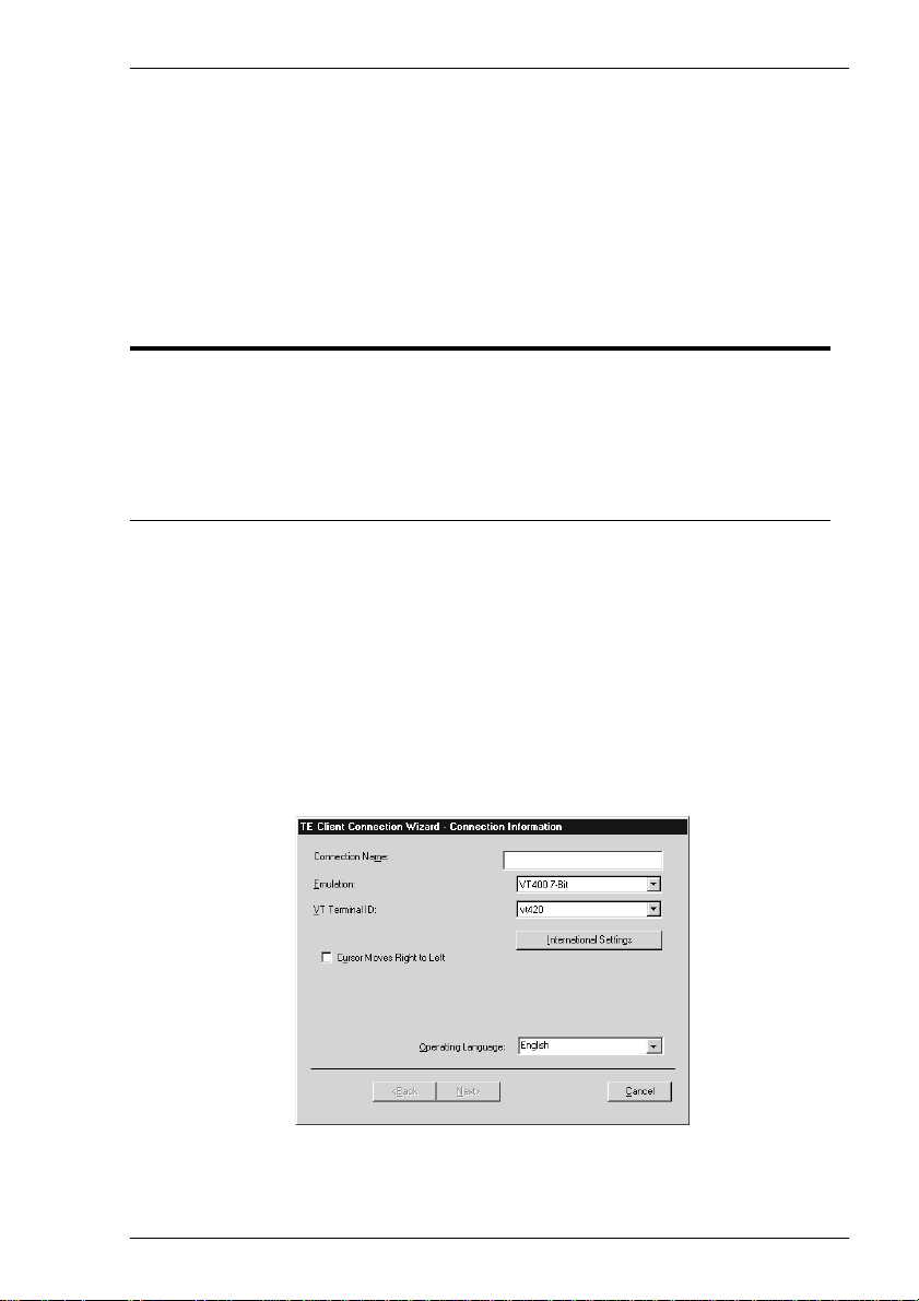
2. Select Terminal Emulation Client and click OK. The Connection Information dialog box will be displayed.
3. Specify the language to be used in all menus and dialog boxes by making a
selection in the Operating Language list at the bottom of the dialog box.
2-1
Page 14

Getting Started
4. Enter a name which will identify this session configuration for future selection in
the Connection Name box.
5. Select the terminal emulation required in the Emulation list box.
6. If additional configuration options are displayed, make the relevant selections.
Refer to the Terminal Emulation Configuration section later in this chapter for
details.
Clicking the International Settings button will display keyboard language and
character set options for the selected terminal emulation. Refer to the relevant
emulation settings dialog box description in the Setup Menus chapter for details.
(Note that the DEC VT options are located in the Emulation and Terminal
Settings dialog boxes.)
7. Click Next to display the Host Information dialog box. If the IBM 3270 emula-
tion was selected, the second dialog box shown below will be displayed.
2-2
Page 15
Getting Started
For a TCP/IP connection, click the TCP/IP button and enter the name or internet
address of the host computer in the Host Name box. Selecting the Host Rollover
On Connection Fail option will present four Host Name entry boxes. The
emulator will attempt to connect to each specified host in turn until one is successful. Click Advanced for Telnet options. Refer to the TCP/IP Connection Settings
section later in this chapter for details.
For a serial connection, click the Serial button, specify the communications port in
the Connect To box, then click Advanced for additional serial options. Refer to
the Serial Connection Settings section later in this chapter for details.
The IBM 3270 emulation enables you to specify up to four hosts and you can use
keyboard commands to switch between the sessions as described in the IBM
3270 Emulation chapter. Enter the name or internet address of the host
computer(s) in the Host box(es), then click Advanced for Telnet options. Refer
to the TCP/IP Connection Settings section later in this chapter for details.
Make the relevant selections then click OK to return to the Host Information
dialog box, then click Next to display the Automate Login Process dialog box.
8. The Automate Login Process dialog box gives you the option to automate part or
all of the host login procedure. Refer to the Automate Login Process section later
in this chapter for details.
Make the relevant selections if required then click Next to display the Printer Port
Settings dialog box.
9. The next dialog box in the Connection Wizard enables you to specify Printer Port
Settings. Refer to the Printer Port Settings section later in this chapter for details.
2-3
Page 16
Getting Started
Make the relevant selections if required then click Next to display the GUI
Overrides dialog box.
10. The GUI Overrides dialog box allows you to disable various GUI items and also
enables you to specify how the emulator responds when the host closes the
connection. Refer to the GUI Overrides section later in this chapter for details.
Make the relevant selections if required then click Next to display the Aux Port
Settings dialog box.
11. The Aux Port Settings dialog box enables you to specify a COM or LPT port for
bidirectional output when in any DEC VT mode, ANSI BBS, Sco Console, HP
700-92/96 or IBM 3151 mode.
2-4
Page 17
Getting Started
12. When you have made your selections, click Finish to return to the Terminal
Connection Manager.
13. In the Terminal Connection Manager, display the Connections list, select the
session name you specified earlier in step 4, then click the Connect button.
2-5
Page 18

Getting Started
T erminal Emulation Configuration
Emulation Options
The Emulation options in the Connection Wizard Connection Information dialog
box are as follows:
The ADDS A2 emulation provides compatibility with software designed to drive the
ADDS Viewpoint A2 terminal, as emulated by the Wyse WY-50/50+/60 terminals.
Refer to the Wyse Emulations chapter for details.
The AIXTerm emulation provides compatibility with software designed to drive an
X terminal using X Windows.
The ANSI BBS emulation is a derivative of the ANSI device driver ANSI.SYS
supplied with all DOS based PCs and which provides the screen management for the
DOS console screen. PC based UNIX systems and Bulletin Board Systems (BBS)
often rely on the ANSI emulation when being accessed by a PC.
The AT 386 emulation provides compatibility with software designed to drive the
AT&T AT 386 terminal.
The DG 410/412 emulation provides compatibility with software designed to drive
the Data General D410 and D412 terminals. Refer to the DG 410/412 Emulation
chapter for details.
The HP 700-92/96 emulation provides compatibility with software designed to drive
the Hewlett Packard 700/92, 2392A, 2622A, 70094 and 70096 terminals. This
emulation is described in detail in the HP 700-92/96 Emulation chapter.
The HZ1500 emulation provides compatibility with software designed to drive the
Hazeltine 1500 terminal, as emulated by the Wyse WY-50/50+/60 terminals. Refer to
the Wyse Emulations chapter for details.
The IBM 3151 emulation provides compatibility with software designed to drive the
IBM 3151 terminal. Refer to the IBM 3151 Emulation chapter for information on this
emulation.
The IBM 3270 emulation provides compatibility with software designed to drive the
IBM 3270 terminal. Note that the initial display will be an ASCII text screen known
as Network Virtual Terminal mode (NVT mode for short). The setting of the IBM
3270 Model option determines the size of the display and whether or not extended
attributes are supported. Refer to the IBM 3270 Emulation chapter for details.
The IBM 5250 emulation provides compatibility with software designed to drive
IBM 5250 type alphanumeric terminals. This emulation can be used for connection to
an IBM AS/400, System/36 or System/38. Note that the initial display will be an
ASCII text screen known as Network Virtual Terminal mode (NVT mode for short).
Refer to the IBM 5250 Emulation chapter for details.
Sco Console is an emulation of the SCO UNIX box.
2-6
Page 19

Getting Started
The TA6530 emulation provides compatibility with software designed to drive the
Tandem 6530 terminal. This emulation is described in the TA6530 Emulation
chapter.
The TVI 910, TVI 920 and TVI 925 emulations provide compatibility with software
designed to drive the TeleVideo 910, 920 and 925 terminals, respectively, as
emulated by the Wyse WY-50/50+/60 terminals. Refer to the Wyse Emulations
chapter for details.
The TVI 950 and TVI 955 emulations provide compatibility with software designed
to drive the TeleVideo 950 and 955 terminals, respectively.
The VT52 and VT100 emulations enable you to run applications written for the DEC
VT52 and VT100 terminals, respectively. Refer to the DEC VT Emulations chapter
for information on these emulations.
The VT500 7-Bit and VT500 8-Bit emulations enable you to run applications written
for the DEC VT320 terminal, the difference is in their treatment of 8-bit control
codes. When VT500 7-Bit is selected, all 8-bit codes are converted to their 7-bit
equivalents, whereas VT500 8-Bit leaves 8-bit codes unchanged. If you are using
VT200 applications, select VT500 7-Bit. Refer to the DEC VT Emulations chapter
for information on these emulations.
The VT PCTerm emulation provides compatibility with software designed for the PC
Term mode supported by DEC. This is the same as the VT510 emulation except that
keyboard scan codes are sent on key press/release instead of ASCII codes by default.
The WYSE PCTerm emulation provides compatibility with software designed for the
PC Term personality supported by Wyse. Keyboard scan codes are sent on key press/
release instead of ASCII codes by default.
The WY50, WY50+ and WY60 emulations provide compatibility with software
designed to drive the Wyse WY-50, WY-50+ and WY-60 terminals, respectively.
Refer to the Wyse Emulations chapter for information on these emulations.
DEC Suite Options
The VT Terminal ID option applies to the DEC VT emulations. It specifies what is
reported back to the host in response to a terminal identification request. (Note that
not all features of the specified terminal may be supported.)
The Cursor Moves Right to Left option applies to the DEC VT, Ansi BBS,
AIXTerm, AT 386 and Sco Console emulations. It enables you change the direction
in which the text cursor moves across the display.
The High Function Terminal option is displayed when the AIXTerm emulation is
selected. This enables you to switch between HFT (High Function Terminal) mode
(default) and VT100 mode.
2-7
Page 20

Getting Started
HP 700-92/96 Option
The HP Model option specifies what is reported back to the host in response to a
terminal identification request. This can be set to 70092 (default), 2392A, 2622A,
70094 or 70096. (Note that not all features of the specified terminal may be
supported.)
IBM 3151 Option
The setting of the Model option identifies the terminal model being emulated in
response to a terminal identification request from the host. Model 11 supports only
one viewport containing 24 or 25 rows and 80 columns. Model 31 supports up to
three viewports (80 or 132 columns wide) and pass-through printing.
IBM 3270 Options
The setting of the IBM 3270 Model option specifies what is reported back to the host
in response to a terminal identification request. (Note that not all features of the
specified terminal may be supported.) TN3287 printing is supported by selecting
3287-1.
One of four display sizes can be selected:
3278/9-2 24 rows by 80 columns
3278/9-3 32 rows by 80 columns
3278/9-4 43 rows by 80 columns
3278/9-5 27 rows by 132 columns
3278 settings with the E extension provide support for the following extended
attributes (these are supported by the 3279 as standard):
3270 Field Attributes
Extended Highlighting
Foreground Colour
Query Reply Inbound Structured Fields
The setting of the Left Ctrl acts as Reset Key option determines whether or not the
left Control key performs the same function as the Reset key.
The setting of the Right Ctrl acts as Enter Key option determines whether or not
the right Control key performs the same function as the keypad Enter key.
IBM 5250 Options
The IBM 5250 Model option specifies what is reported back to the host in response
to a terminal identification request. (Note that not all features of the specified terminal
2-8
Page 21

Getting Started
may be supported.) The terminal models and their display characteristics are listed
below:
Model Display Rows x Columns
5291_1 Monochrome 24 x 80
5292_2 Colour 24 x 80
5251_11 Monochrome 24 x 80
3179_2 Colour 24 x 80 (default)
3196_A1 Monochrome 24 x 80
3180_2 Monochrome 24 x 80 and 27 x 132
3477_FC Colour 24 x 80 and 27 x 132
3477_FG Monochrome 24 x 80 and 27 x 132
3486_BA Monochrome 24 x 80
3487_HA Monochrome 24 x 80
3487_HC Colour 24 x 80
The printer models are listed below:
3812-1 Single byte printer
The setting of the IBM 5250 Monochrome option will match the normal display
characteristic of the selected IBM 5250 model by default. Note that the emulation of
all IBM 5250 models supports both monochrome and colour display. When
monochrome is selected, characters will be displayed in green and intense fields will
be displayed in white. When monochrome is not selected, the settings specified in the
Attributes dialog box (described in the Setup Menus chapter) will be used for the
display.
The setting of the Left Ctrl acts as Reset Key option determines whether or not the
left Control key performs the same function as the Reset key.
The setting of the Right Ctrl acts as Enter Key option determines whether or not
the right Control key performs the same function as the keypad Enter key.
The setting of the Carriage Return acts as Enter Key option determines whether or
not the Return key performs the same function as the keypad Enter key.
2-9
Page 22
Getting Started
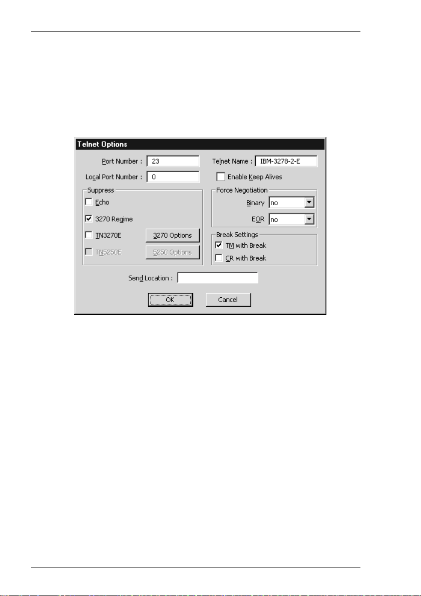
TCP/IP Connection Settings
The TCP/IP Telnet Configuration dialog box can be displayed from the Connection
Wizard Host Information dialog box by setting the Connection Type to TCP/IP
then clicking the Advanced button, or the New Connection dialog box when in non-
WBT mode by selecting TCP/IP in the Type list box then clicking the Configure
button.
Note that the options available and the default settings depend on the current terminal
emulation.
Host Port Number
This enables you to specify the Telnet port number. The default Telnet port number,
23, can be substituted with any valid 16 bit port number. Specifying a number outside
the valid range will cause the setting to default to 1.
Local Port Number
This enables you to specify the local Telnet port number if required. Setting this to 0
will cause the number to be allocated automatically.
Telnet Name
This enables you to override the name that will be reported for the terminal type over
Telnet.
Enable Keep Alives
Selecting this option will prevent the session from being disconnected from the host by
an inactivity timeout.
2-10
Page 23

Getting Started
Suppress Echo
When selected, this will will prevent the emulator from generating the Telnet echo
option on connection.
Suppress 3270 Regime
When running the IBM 3270 emulation, the setting of this option determines whether
or not support for the Telnet "3270 regime" option is suppressed.
Suppress TN3270E
When running the IBM 3270 emulation, the setting of this option determines whether
or not support of TN3270E is suppressed. When this option is not selected (i.e.
TN3270E is not suppressed), additional options are available by clicking the 3270
Options button. These are described in the TN3270 Options section.
Suppress TN5250E
When running the IBM 5250 emulation, the setting of this option determines whether
or not support of TN5250E is suppressed. When this option is not selected (i.e.
TN5250E is not suppressed), additional options are available by clicking the 5250
Options button. These are described in the TN5250 Options section.
Force Negotiation
These settings determine whether or not the Telnet Binary or EOR options are supported. Both are set to no by default.
No Will not force any negotiations. It will leave it up to the
host to decide what to do.
DO Will force negotiation. The host will be informed that the
option is supported.
DONT Will force negotiation. A negotiation packet will be sent
to the host telling it that the option is not supported.
Break Settings
The setting of these options determine whether or not a timing mark (TM) and/or
carriage return (CR) is sent with a Telnet break packet. A timing mark is sent by default.
Send Location
This enables you to enter the location of this terminal which may be used by the host
to provide a list of users currently logged in giving their name and location.
2-11
Page 24
Getting Started
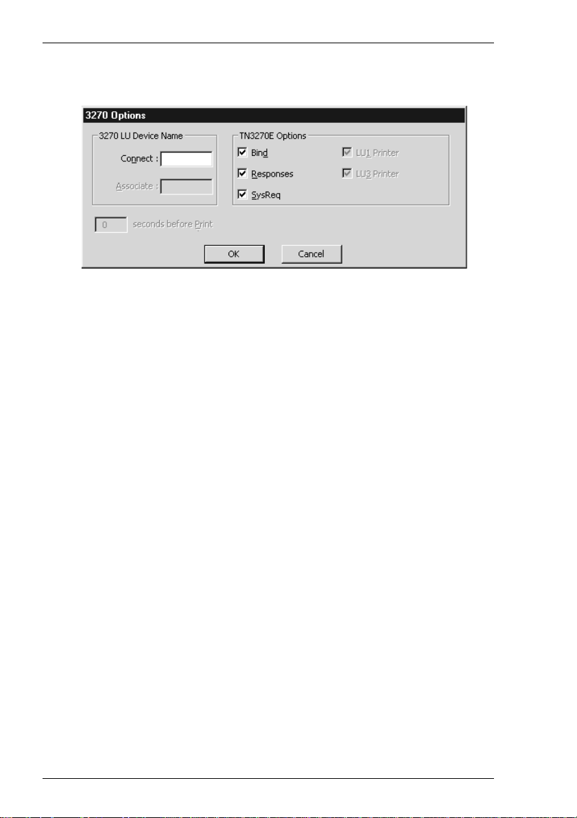
TN3270 Options
This dialog box is displayed by clicking the 3270 Options button in the TCP/IP
Telnet Configuration dialog box when TN3270 is not suppressed.
Connect
This specifies the name of the device which the server will be requested to assign to
the Telnet session; it may be used when requesting either a terminal or a printer
session.
You can return the local host name by entering %s after the device name. To return
the user name, enter %u after the device name. You can specify how many
characters of the name is returned in each case. For example, %.3s will return the
first three characters of the local host name, and %-.3s will return the last three
characters.
To automatically assign a new device name for each successive connection, either
enter %dN% after the name, where N is a decimal value, or %xN%, where N is a
hexadecimal value. Each time the host requests the device name a counter will be
substituted into the device name. If the host rejects the device name as in use the
counter will be incremented modulus N and the name retried until all possibilities
have been tried, at which point the emulation will report a device name rejected error.
For example, TEST%d4% will give TEST1 on all connections until the host rejects
the name as in use, in which case TEST2 will be used. If this is already in use then
TEST3 is used, or if already in use then TEST0. These values are preserved over
power off, so the first connection of any given power on may not be TEST1. Assume
that the start point is random.
Note: There are separate counters for the IBM 3270 and IBM
5250 emulations.
When you achieve a TN3270E connection, the LU device name that you are
connected as will be displayed on the status line. If the specified device is rejected by
the server or host, then an error message box will be displayed indicating the reason.
2-12
Page 25

Getting Started
Associate
This is available when the IBM 3270 Model option is set to 3287-1 (a printer). It is
used to request that the device name of the printer associated with a particular terminal is assigned to this Telnet session. The name of the terminal is specified here.
(This is implemented as described in RFC 1647.)
TN3270E Options
TN3270E in implemented as described in RFC 1647. These options should not be
changed unless required by your System Administrator.
The Bind setting determines whether or not the server is allowed to send the SNA
Bind image and Unbind notification to the emulator.
When Responses is selected, positive and negative response handling is supported. It
allows the server to reflect to the emulator any and all definite, exception, and no
response requests sent by the host application.
When SysReq is selected, some (or all, depending on the server) of the functions of
the SysReq key will be emulated and the server in an SNA environment.
The LU1 and LU3 Printer options are available when the IBM 3270 Model option
is set to 3287-1 (a printer). They enable you to specify which printer type(s) to
support.
2-13
Page 26
Getting Started
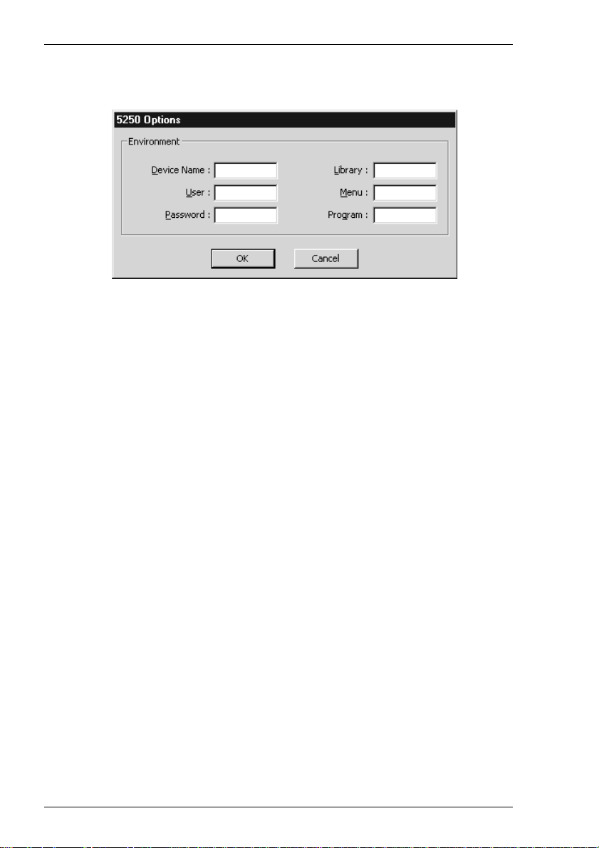
TN5250 Options
This dialog box is displayed by clicking the 5250 Options button in the TCP/IP
Telnet Configuration dialog box when TN5250 is not suppressed and the IBM
5250 Model is not set to a printer. Refer to the next section for 5250 Printer
Options.
Device Name
This enables you to enter the name of the device which the server will be requested
to assign to this Telnet session.
You can return the local host name by entering %s after the device name. To return
the user name, enter %u after the device name. You can specify how many
characters of the name is returned in each case. For example, %.3s will return the
first three characters of the local host name, and %-.3s will return the last three
characters.
To automatically assign a new device name for each successive connection, either
enter %dN% after the name, where N is a decimal value, or %xN%, where N is a
hexadecimal value. Each time the host requests the device name a counter will be
incremented modulus N and substituted into the device name.
For example, TEST%d4% will give TEST1 on first connect, TEST2 on second,
TEST3 on third, TEST0 on fourth, TEST1 on fifth and so on.
TEST%d100% will give TEST1 on first connect, TEST2 on second, ... TEST99 on
99th, TEST0 on 100th, TEST1 on 101st and so on.
These values are preserved over power off, so the first connection of any given
power on may not be TEST1. Assume that the start point is random. In addition there
is a single counter for the unit so concurrent sessions will start from subsequent
values. For example, if session one uses TEST1 then session two will use TEST2.
Where a device name collision occurs (i.e. the device name is already in use on the
host) the host will ask again for the device name during the same connection. In this
case TEST1, TEST2, ... may all be tried in one connection until the host accepts one,
2-14
Page 27

Getting Started
or all possibilities have been tried. In the latter case the same name is sent twice in
succession to indicate to the host all names have been tried.
If concurrent 5250 sessions are started before a previous session has negotiated an
acceptable device name, it is possible that the two sessions will access the counter
simultaneously and not all possible names will be tried by each session. This should
not cause a problem unless the separate sessions use different modulo values (for
example, session one device name TEST%d4% and session two device name
ANOTHER%d100%) or are connecting to different hosts.
Note: There are separate counters for the IBM 3270 and IBM
5250 emulations.
User, Password, Library, Menu
These options enable you to specify the initial entries required on the standard startup
screen so that it can be bypassed. Each entry can be a maximum of ten characters.
Program
This enables you to specify the name of the initial program to run. The entry can be a
maximum of ten characters.
2-15
Page 28
Getting Started
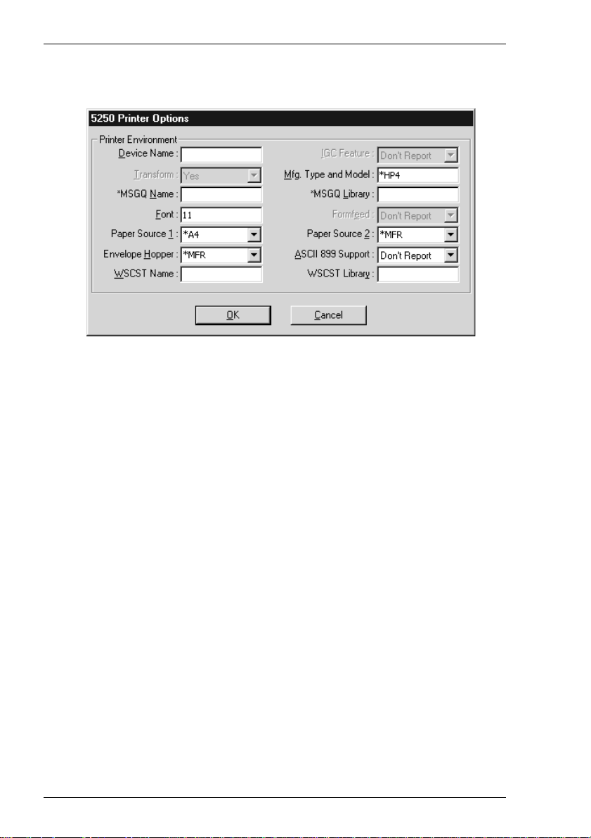
5250 Printer Options
This dialog box is displayed by clicking the 5250 Options button in the TCP/IP
Telnet Configuration dialog box when TN5250 is not suppressed and the IBM
5250 Model is set to 3812-1 (a printer).
Device Name
Specifies the name of the printer device.
IGC Feature
This is always set to Don't Report.
Transform
Specifies whether the printer will use the host print transform function to generate
ASCII printer data. This is always set to Yes. The Mfg. Type and Model option must
specify the printer manufacturer, type and model.
Mfg. Type and Model
Specifies the manufacturer, type and model of the printer. The entry must exactly
match an AS400 printer type string, including the * (asterisk) character. The
following valid entries are for the IBM AS/400 V3R1. Note that the list can change
according to AS/400 settings.
*IBM2380 *IBM2381 *IBM2390 *IBM2391 *IBM3812
*IBM3816 *IBM3912HP *IBM3916HP *IBM39302 *IBM39303
*IBM4019 *IBM4019HP *IBM4029 *IBM4029HP *IBM4037
*IBM4039HP *IBM4070 *IBM4070EP *IBM4072 *IBM4076
*IBM42011 *IBM42012 *IBM42013 *IBM42021 *IBM42022
2-16
Page 29

Getting Started
*IBM42023 *IBM42071 *IBM42072 *IBM42081 *IBM42082
*IBM4212 *IBM4216 *IBM4226 *IBM4230 *IBM4232
*IBM47121 *IBM47122 *IBM47221 *IBM47222 *IBM4770
*IBM5152 *IBM5201 *IBM5202 *IBM5204 *IBM5216
*IBM6404 *IBM6404EP *IBM6408 *IBM6408EP *IBM6412
*IBM6412EP *HPII *HPIID *HPIIP *HPIII
*HPIIID *HPIIIP *HPIIISI *HP4 *HP310
*HP500 *HP520 *HP550C *HP560C *HPPAINT
*CPQPM15 *CPQPM20 *EPAP2250 *EPAP3250 *EPAP5000
*EPAP5500 *EPDFX5000 *EPDFX8000 *EPFX850 *EPFX870
*EPFX1170 *EPLX810 *EPLQ510 *EPLQ570 *EPLQ860
*EPLQ870 *EPLQ1070 *EPLQ1170 *EPLQ2550 *EPSQ870
*EPSQ1170 *EPEPL7000 *EPEPL8000 *NECP2 *NECP2200
*NECP2200XE *NECP5200 *NECP5300 *NECP6200 *NECP6300
*OKI184IBM *OKI320IBM *OKI321IBM *OKI390IBM *OKI391IBM
*OKI393IBM *OKI590IBM *OKI591IBM *OKI400 *OKI800
*OKI810 *OKI820 *OKI3410 *PAN1123EP *PAN1124EP
*PAN1124IEP *PAN1180EP *PAN1180IEP *PAN1191EP *PAN1624EP
*PAN1654EP *PAN1695EP *PAN2123EP *PAN2124EP *PAN2180EP
*PAN2624EP *PAN4410HP *PAN4420HP *PAN4430HP *PAN4450IHP
*PAN4451HP
*MSGQ Name
Specifies the name of the message queue to which operational messages for the
printer are to be sent.
*MSGQ Library
Specifies the message queue library.
Font
Specifies the font identifier and point size used by the single-byte printer (e.g. 11).
Formfeed
This is always set to Don't Report. The Paper Source 1 option is used to specify the
paper format to be used.
Paper Source 1 & 2
These options specify the paper format to be used. The possible settings are:
Don't Report No value returned.
*NONE No paper source is defined.
*MFR The system determines the paper type used based on
the manufacturer, type and model of the printer.
*LET Letter-sized paper (8.5 x 11 inches).
2-17
Page 30

Getting Started
*LEGL Legal-sized paper (8.5 x 14 inches).
*EXEC Executive-sized paper (7.25 x 10.5 inches).
*A4 A4-sized paper (210 mm x 297 mm).
*A5 A5-sized paper (148 mm x 210 mm).
*B5 B5-sized paper (182 mm x 257 mm).
*C80 Continuous-form paper, 8.0 inches wide
(Paper Source 1 only).
*C132 Continuous-form paper, 13.2 inches wide
(Paper Source 1 only).
*A3 A3-sized paper (297 mm x 420 mm).
*B4 B4-sized paper (257 mm x 364 mm).
*LEDG Ledger-sized paper (11 inches x 17 inches).
Envelope Hopper
This specifies the envelope format to be used. The possible settings are:
Don't Report No value returned.
*NONE No envelope source is defined.
*MFR The system determines the envelope type used based on
the manufacturer, type and model of the printer.
*B5 B5-sized envelopes (176mm x 250mm).
*MON Monarch-sized envelopes (3.875 x 7.5 inches).
*N9 Number 9-sized envelopes (3.875 x 8.875 inches).
*N10 Number 10-sized envelopes (4.125 x 9.5 inches).
*C5 C5-sized envelopes (162mm x 229mm).
*DL DL-sized envelopes (110mm x 220mm).
ASCII 899 Support
Specifies whether the single-byte printer has ASCII code page 899 installed. Selecting Don't Report will cause no value to be returned.
WSCST Name
Specifies the name of the object containing pointers to the work station customizing
tables.
WSCST Library
Specifies the library name of the object containing pointers to the work station
customizing tables.
2-18
Page 31

Getting Started
Serial Connection Settings
The Serial Configuration dialog box can be displayed from the Connection Wizard
Host Information dialog box by setting the Connection Type to Serial then
clicking the Advanced button, or the New Connection dialog box when in non-
WBT mode by selecting Serial in the Type list box then clicking the Configure
button.
Baud Rate
Factory default: 9600
This specifies the transmit and receive baud rates for the port selected for host com-
munications.
Parity
Factory default: None
This option specifies the parity mode for each transmitted character. If the number of
Data Bits is 8, set this option to None.
Selecting Odd will cause an eighth bit to be added with a value of 1 if the previous 7
bits add up to an even number, and 0 if the previous 7 bits add up to an odd number.
Selecting Even will cause an eighth bit to be added with a value of 1 if the previous 7
bits add up to an odd number, and 0 if the previous 7 bits add up to an even number.
Mark parity will set every eighth bit to 1 and Space parity every bit to 0.
Flow Control
Factory default: Input
This option specifies the type of flow control used by the line port to communicate
readiness to transmit or receive data from the host.
None - No flow control
Input - XON/XOFF on received data
Output - XON/XOFF on transmitted data
2-19
Page 32

Getting Started
In/Out - XON/XOFF on transmitted & received data
Hardware - DTR/CTS hardware flow control.
Data Bits
Factory default: 8
This option specifies the number of data bits sent for each transmitted character.
Stop Bits
Factory default: 1
This specifies the number of stop bits sent for each transmitted character.
Transmit Rate
Factory default: Unlimited
The setting of this option determines the maximum effective baud rate that the
emulatortransmits terminal reports and data sent as a result of pasting data to the host.
Local Echo
Factory default: Unselected
The setting of this option determines whether keyboard entered characters are dis-
played on the screen as well as sent to the host. When unselected, characters are not
displayed when they are transmitted unless the host 'echoes' them back.
2-20
Page 33

Getting Started
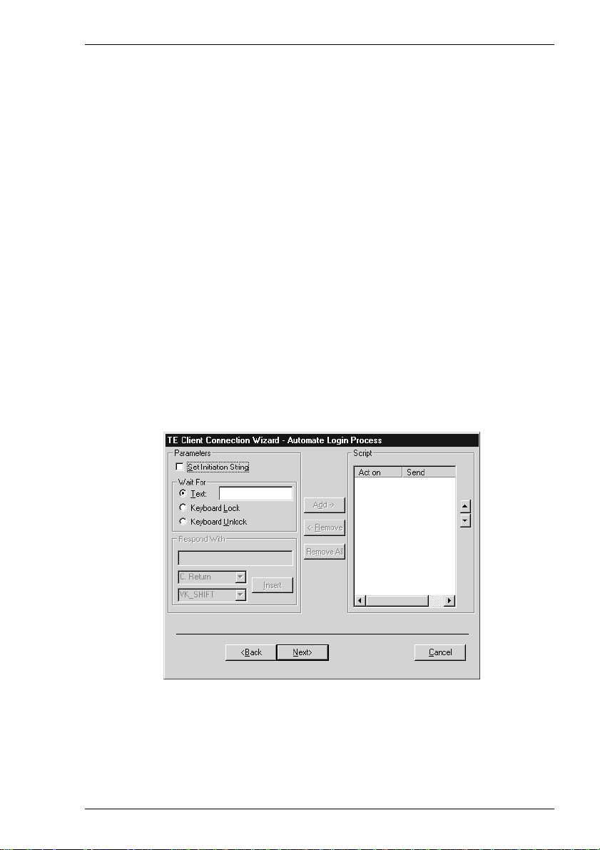
Automate Login Process
The Automate Login Process dialog box enables you to automate part or all of the
host login procedure.
The settings in this dialog box enable you to specify what is sent to the host in
response to prompts displayed on the screen.
1. If an initiation string is required by the host when you first make a connection,
select the Set Initiation String option, enter the required characters in the
Initiate with box (the Respond With box in the illustration above), then click
the Add button. The initiation string will be added to the Script window on the
right.
2. The Wait For options enable you to specify the prompt or keyboard locked or
unlocked command that the automatic login process is to wait for before proceeding. Some systems are case sensitive, so make sure your Text entries follow the
correct conventions for your system.
Note: When running the IBM 3270 or IBM 5250 emulation, Text
entries are only applicable in NVT mode.
3. Enter the response required in the Respond With box. In order for a text entry to
be sent to the host it must be followed by a carriage return command. This is
specified by selecting C. Return in the list of predefined commands in the list
box below then clicking the Insert button. A <CR> will appear in the Respond
With box.
You can also enter a predefined key function in the Respond With box by
selecting Key Definition in the list of predefined commands in the list box
2-21
Page 34

Getting Started
below, selecting one of the virtual key names listed in the box below that, then
clicking the Insert button. The Virtual Key Names appendix lists the predefined
key functions available for each emulation.
The list of predefined commands that can be inserted include UserName
(indicated by <UN>) and Password (indicated by <PW>). Selecting either of
these will cause a dialog box to pop-up when logging on to the host prompting
the user to enter a name or password, respectively. You can also delay the script
response by 2 seconds by inserting Delay (2s) (indicated by <D>) or 0.255
seconds by inserting Pause (0.255) (indicated by <P>).
4. When you have finished specifying the response to a particular prompt, click the
Add button to add the definition to the Script window on the right.
The script will perform the actions in the order displayed in the Script window.
To change the order of the script lines, use the up and down arrow buttons to the
right of the Script window.
5. Repeat this procedure for each prompt as required.
If you want to edit one of the script lines, select the line in the Script window
then click Remove to send it to the edit boxes on the left. Make the change(s)
then click Add to send it back to the script. Note that this will now be the last line
of the script.
6. When the Script window contains all the required responses to the relevant
prompts in the correct order, click Finish.
2-22
Page 35

Getting Started
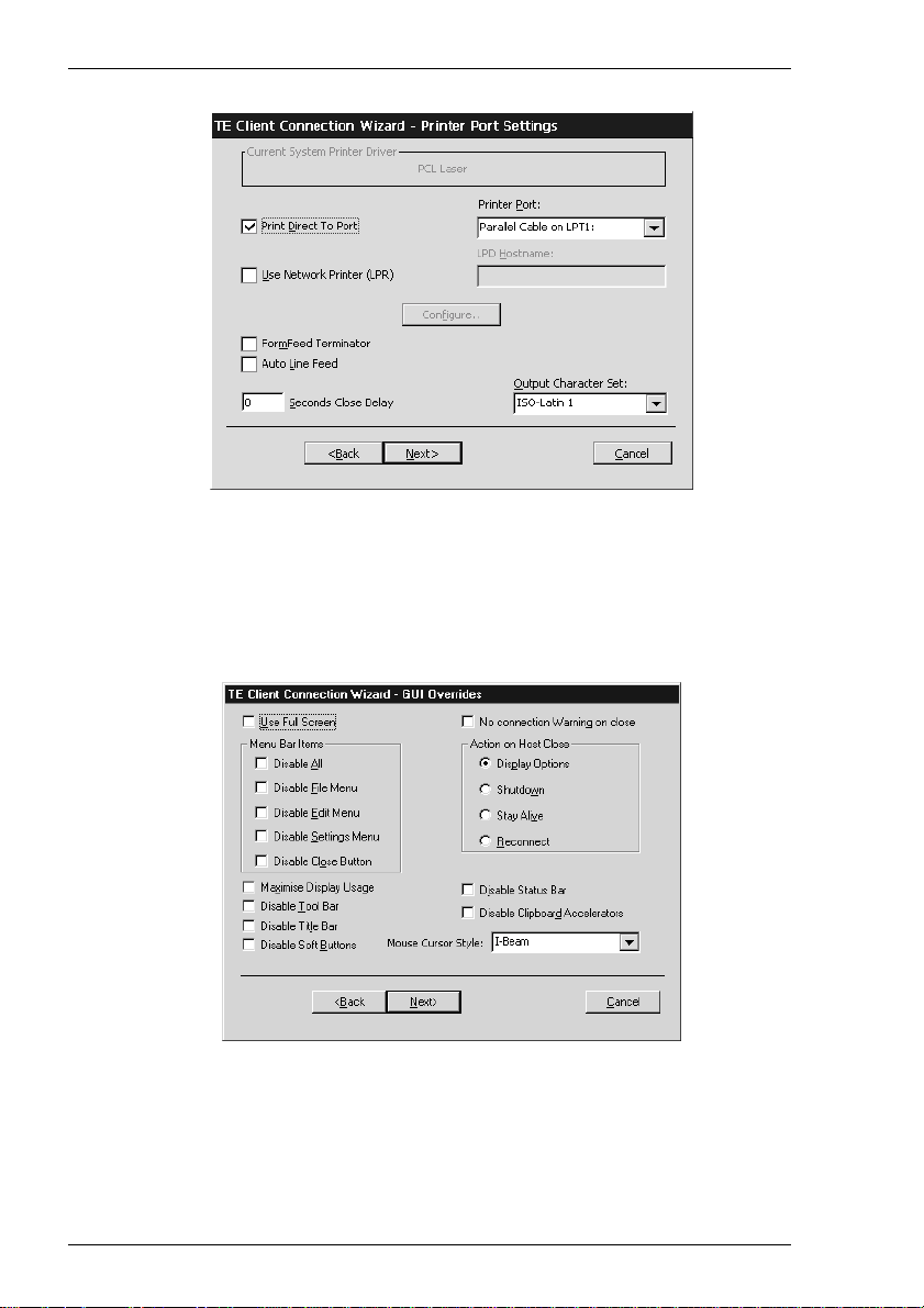
Printer Port Settings
The Printer Port Settings dialog box enables you to direct print data to a printer handled by the Print Manager, a specific port, or a network printer.
Direct Print Data To The Print Manager
The Current System Printer Driver box displays the name of the currently selected
system printer when both the Use Network Printer (LPR) and Print Direct To Port
options are not selected.
Clicking the Configure button will display a Print Manager dialog box which enables
you to specify printer settings.
If you find a through print results in data being split into lines, each treated as a
separate print job, specify a time in the Seconds Close Delay box (e.g. 5 seconds).
This will enable the next line of data to be sent before the print job is assumed to have
finished and therefore prevents the print job from being closed prematurely. When set
to 0, printing will not start until a ‘print end of job’ command is received from the
host. Entering any other number will cause printing to start after the specified number
of seconds have elapsed, regardless of whether the ‘print end of job’ command has
been received from the host.
Direct Print Data To A Specific Port
To direct print data to a specific port, select Print Direct To Port and specify the
Printer Port.
Selecting the FormFeed Terminator option will cause the printer to advance the
paper to the top of the form when it has finished printing.
2-23
Page 36

Getting Started
The Output Character Set option enables you to specify the character set used for
printing when Print Direct To Port is selected. This allows non-ISO Latin-1 printers
to be used.
Selecting Auto Line Feed will cause the printer to print at the beginning of the next
line when a carriage return command is received.
When a serial port is selected, clicking the Configure button will display a dialog box
in which you can specify the baud rate, parity, flow control, data bits and stop bits
settings. These options are described in the Serial Settings section.
Direct Print Data To A Network Printer
To direct print data to a printer on the network, select Use Network Printer (LPR)
and enter the LPD Hostname. Clicking the Configure button will display a dialog
box which enables you to specify various print settings.
You must specify the Printer Name. The Job Name and User Name entries are
optional (the User Name will default to root if none is specified). You can specify
how many times the LPR protocol will attempt to execute the print job before
cancelling by setting the number of Retries and the number of seconds delay between
each attempt. When Add Banner is selected, information about this print job will be
printed with it. You can display a message box which will indicate the progress of the
print job by selecting Debug Information.
2-24
Page 37

Getting Started
GUI Overrides
The GUI Overrides dialog box enables you to disable various GUI items and also enables you to specify how the emulator responds when the host closes the connection.
Selecting the Use Full Screen option will cause the emulation workspace to fill the
entire display while retaining the default number of lines and columns. Note that the
title bar, menu bar, tool bar and soft buttons will not be displayed even if they are
enabled. The menus can be accessed by using the relevant keyboard accelerators.
Selecting the Maximise Display Usage option will cause the teemtalk window to be
displayed at the maximum size possible while retaining the default number of lines
and columns and including all window elements if enabled (title bar, menu bar, etc.).
The Disable options enable you to disable any or all of the menu bar items, the title
bar, tool bar, soft buttons and the status bar.
The Disable Clipboard Accelerators option will disable the Ctrl + C (copy) and
Ctrl + V (paste) keyboard commands.
By default, a warning message will be displayed if you attempt to exit the emulator
while a host connection is still active. You can disable this message by selecting the
No connection warning on close option.
The Action on Host Close options enable you to specify how the emulator responds
when the host closes the connection. Selecting Display Options will cause a dialog
box to be displayed with the following three options. Selecting Shutdown will cause
the emulator to shutdown. Selecting Stay Alive will keep the emulator running.
Selecting Reconnect will cause the emulator to attempt to reconnect to the host.
The Mouse Cursor Style option enables you to choose from a range of cursor styles.
2-25
Page 38

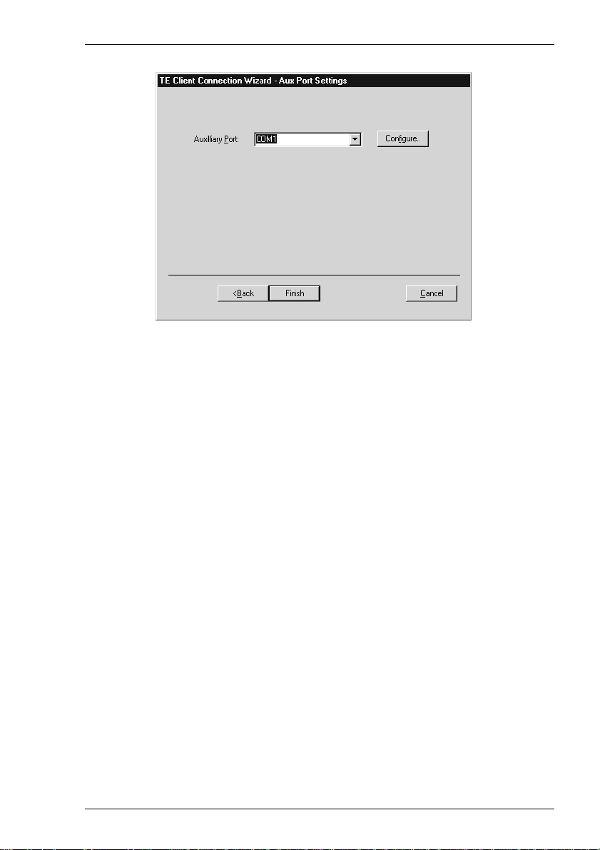
Getting Started
Aux P ort Settings
The Aux Port Settings dialog box enables you to specify a COM or LPT port for
bidirectional output when in any DEC VT mode, ANSI BBS, Sco Console HP 70092/96, or IBM 3151 mode.
Clicking the Configure button will display a dialog box in which you can specify
settings for the COM port. The options in it are described in the Serial Settings
section earlier in this chapter.
2-26
Page 39

Getting Started
Emulator Window Features
The Menu Bar
The menu bar provides access to a series of commands and dialog boxes which enable
you to perform various functions and configure the emulator for compatibility with the
application.
One of three menus may be displayed at any one time. These are headed File, Edit,
and Settings.
Note: The options available in the menus depend on whether or not
you are in WBT mode.
To display a menu:
Mouse: Click the title of the menu required.
Keyboard: Hold down the Alt key and press the key bearing the underlined
character in the menu title. For example, pressing Alt + F will display
the File menu.
When the menu bar is not displayed you can still display the menus by pressing the
following keys:
Alt + F for the File menu
Alt + T for the Edit menu
Alt + S for the Settings menu
Refer to the Setup Menus chapter for a complete description of all the menu options.
2-27
Page 40

Getting Started
The Toolbar
A toolbar is displayed below the menu bar. This displays a series of buttons which
provide a quick way of actioning commands or displaying setup dialog boxes when
clicked.
You can redefine all the buttons and add or remove buttons from the toolbar using the
Button Tools dialog box. Refer to the chapter entitled The Toolbar for a complete
description of all the default buttons and how to redefine the toolbar.
The Soft Buttons
A set of soft buttons can be displayed along the bottom of the emulator window.
These can be programmed so that they perform various functions when clicked.
There are four soft button levels. Each level consists of twelve programmable
buttons, providing a combined total of 48 programmable buttons. You can display all
four levels at the same time if required. All levels are accessible even if not all are
displayed, levels stored off-screen can be 'scrolled' into view by clicking the Level
button.
The soft buttons are programmed using the Soft Buttons dialog box, which is displayed by selecting Settings in the menu bar then Soft Buttons... The setting of the Visible Levels option determines how many soft button levels are displayed. Refer to the Setup Menus chapter for information on programming the buttons.
The Status Bar
Along the bottom of the display is a status bar which shows the status of various
operations and enables you to switch between modes. The information displayed in
the status bar depends on the current terminal emulation. The following description
applies when running any of the DEC VT terminal emulations, though some of the
fields and buttons will be applicable to other emulations as well.
2-28
Page 41

Getting Started
123 4 5 6 7 8 9 10 11
Item 1: This displays two LEDs. The first LED indicates whether or not you are
connected to the host. It will show red when not connected and green
when you are connected. The second LED indicates whether or not data
is being sent to or from the host. It will show dull green when there is no
activity, red when data is being sent to the host, and bright green when
data is being received from the host.
Item 2: This button enables you to switch between Local and Online mode. The
label indicates the mode you will switch to if the button is clicked.
Item 3: This button enables you to Pause or Resume scrolling data in the
window. The label indicates the action that will be taken if the button is
clicked.
Item 4: Indicates the current terminal emulation.
Item 5: This displays the active session (always 1), the current page number
(always 1), and the line,column location of the text cursor.
Item 6: This indicates whether Overstrike Mode or Insert Mode is currently
selected. In Overstrike Mode (default), new characters will replace
already existing characters at the cursor position. When Insert Mode is
selected, new characters will be inserted at the cursor position without
deleting existing characters, which will move to the right.
Item 7: This will display Edit when the terminal emulation is in Edit mode.
Item 8: This will display the time in 24 hour format when in DEC VT500 mode if
the VT525 set time command has been received from the host.
Item 9: Indicates the status of the printer as follows:
None signifies that the printer is not turned on or not connected, or not
installed in Microsoft Windows.
Not Ready signifies that the printer is not ready to receive data for
printing.
Ready signifies that the printer is ready to receive data for printing.
Auto signifies that the emulation is in Auto Print mode in which the
current cursor line is sent to the printer when a command for the cursor to
move to the next line is issued.
2-29
Page 42

Getting Started
Controller signifies that the emulation is in Printer Controller mode in
which the host has direct control over the printer. Print screen commands
issued from the keyboard or mouse will be ignored.
ErrGen indicates that an error has occurred and a message box will be
displayed indicating the error.
Item 10: This indicates the keyboard mode. It will be blank when the keyboard is
in normal mode and will display DEC when in DEC mode. You can
toggle between normal and DEC mode by pressing the keys Alt + Num
Lock together.
Item 11: Indicates the status of the aux port as follows:
Ready indicates that the aux port is ready for bidirectional output.
In Use indicates that the aux port is currently busy.
Hotspots
A hotspot facility is provided which enables you to invoke a function by clicking on
a keyword displayed on the screen. For example, an application may display
information relating to keys you can press to perform a particular function. Instead of
pressing the key on the keyboard, you could invoke the function by holding down the
Control key and clicking the mouse pointer on the key name on the display
(assuming default mouse configuration).
Hotspots are supported in ALL terminal emulation modes. A set of default keywords
is provided for each mode. These keywords relate to key functions specific to the
emulation. For example, in VT500 mode you can tap on the word Help displayed on
the screen and the emulator will execute the function associated with the Help key.
You can identify hotspots that are currently present in display memory by assigning
the Show Hotspots function to a key + mouse button combination using the Mouse
Button Actions dialog box (refer to the Mouse Functions chapter for details).
Holding down the relevant key and left mouse button will cause all colour attributes
to be temporarily removed from the display and the hotspots will be highlighted with
a red background. Releasing the key and left mouse button will return the display to
its original state.
2-30
Page 43

Keyboard Configuration
Keyboard Configuration
This chapter describes how to configure the keyboard, define key
functions and compose special characters.
Keyboard Mapping
The keyboard is mapped as close as possible to the terminal being emulated. An
llustration showing the mapping of key functions on the 101/102 key Enhanced AT
style keyboard layout is shown in each terminal emulation chapter.
Special key functions supported by each terminal emulation can be mapped to keys
using the predefined macros listed in the Define Keyboard Macros dialog box as
described in the next section.
3
Defining Key Functions
You can redefine the function of keys on the keyboard using the Define Keyboard Macros dialog box which is displayed by selecting Keyboard Macros in the Settings menu.
3-1
Page 44

Keyboard Configuration
This enables you to redefine the function of most of the keys on your keyboard,
including the key combinations listed below:
Key
Shift + Key
Control + Key
Control + Shift + Key
Alt + Key
Alt + Shift + Key
Alt + Control + Key
Alt + Control + Shift + Key
Each definition may contain a string of up to 127 characters. The combined total of
all the characters that may be programmed into keys is determined by the 127
character limit per definition and the amount of memory available in your terminal.
The Predefined Macros box enables you to select from a list of standard functions
associated with the current terminal emulation. Clicking the arrow button will display
a list box in which the names of valid key functions (called virtual key names) are
shown.
Note: The Virtual Key Names appendix lists all the functions and
associated virtual key names for each terminal emulation.
Note that a virtual key name will be sent across a network as a single packet, whereas
an escape sequence will be split into several packets. If a required function has a
virtual key name equivalent, use this instead of the escape sequence.
A key definition may be actioned locally or transmitted to the host when the key or
key combination is pressed. This is determined by the setting of the Local check box.
When unchecked the definition will be transmitted to the host.
The Current Macro Definitions box displays the key and key combinations that are
currently defined. You can remove the selected definition or delete all the definitions
by clicking the relevant Remove button.
Defining A Key Or Key Combination
1. Click in the Program Key box then press the key or key combination to define.
The current definition will be displayed.
2. Click in the With box then enter the new definition, or make a selection from the
list of Predefined Macros then click Apply.
3. Check the Local check box to make the key definition action locally, or uncheck
it to transmit the definition to the host when the key or key
combination is pressed.
4. Click the Add button to accept the definition. The new definition will be added to
the Current Macro Definitions list.
3-2
Page 45

Keyboard Configuration
Entering Control Characters
You can enter a control character either as the control key character equivalent or the
decimal value of the ASCII character. For example, the control character for the
Return key function, CR (carriage return), can be entered by typing the characters ^
and M, representing the keys Ctrl + M which, when pressed together would
generate the CR code.
Decimal values are entered as three-digit numbers immediately preceded by an
underscore character. Values with only two digits must be preceded by a zero. For
example, the decimal value of CR is 13, so this would be entered as _013.
Refer to the ASCII character table in the Character Sets appendix for code and
decimal references.
Key Combinations & Sequences
You can program a key to perform the function of a combination or sequence of
keys. For example, you can cause the F1 key to perform the same function as
pressing the keys Alt + F4 together, or pressing the keys F2 then F3 then F4.
Keys are identified by their virtual key names as listed in the Virtual Key Names
appendix. The virtual key name has to be enclosed by the < and > characters in the
key definition box. You may omit the VK_ and VT_ (etc.) parts of the virtual key
name.
To program a key so that it performs the same function as pressing two or more other
keys together, type the < character followed by the virtual key names linked together
with + (plus sign) characters and ending with the > character.
For example, to program the F1 key so that when it is pressed it performs the same
function as pressing the keys Alt + F4 together, enter the following characters in the
key definition box:
<ALT+F4>
To program a key so that it performs the same function as pressing a sequence of
keys one after the other, enter each virtual key name in the order required, enclosing
each virtual key name with the < and > characters. Each enclosed virtual key name
must immediately follow the previous enclosed virtual key name with no spaces. For
example, to program the A key so that when it is pressed it performs the same
function as pressing the keys F2 then F3 then F4 enter the following characters in the
key definition box:
<F2><F3><F4>
3-3
Page 46

Keyboard Configuration
Compose Character Sequences
Compose character sequences can be used to generate codes for characters not
shown on your keyboard. The characters that can be composed depend on the setting
of the Character Set Mode option in the Emulation Settings dialog box and the
Preferred Char. Set option in the Terminal Settings dialog box.
When Character Set Mode is is set to National, only characters found in the
character set that corresponds to the selected keyboard nationality can be composed.
When Multinational is selected, the emulator is in Multinational mode and characters from all national keyboard layouts may be composed.
The tables of characters that are used in Multinational mode depend on the setting of
the Preferred Char. Set option. When this is set to DEC-MCS, the ASCII (7-bit)
and DEC Additional (8-bit) character sets are used. When this option is set to ISO
Latin-1, the ASCII (7-bit) and ISO Latin-1 Additional (8-bit) character sets are used.
The Character Sets appendix shows all the tables of characters that may be selected.
If a character is a diacritical symbol (e.g. ´ or ¨) and this symbol does not appear on
the keyboard, an equivalent character can be used in some cases. The diacritical
symbols and the possible substitutes are shown below. There are no equivalents for
the circumflex accent and tilde mark.
Diacritical Mark Equivalent Character
´ Acute accent ' Apostrophe
¨ Umlaut " Double quote
` Grave accent ' Single quote
° Ring mark * Asterisk or degree sign
To compose a character, first find the character you wish to compose in the left hand
column of the following tables. The two characters shown in the right hand column
are the keys that are used to create it. Several alternatives may be given for
generating the same character. A compose sequence is initiated by pressing the keys
Alt + C together, followed by the key bearing the first character then the key bearing
the second character.
Note: The compose character sequence can also be initiated by
pressing a key defined with the COMPOSE virtual key
name.
A compose character sequence may be abandoned before completion by pressing the
Delete key. Pressing Alt + C (or the key defined with the COMPOSE virtual key
name) again before completing a compose character sequence will cause it to be
abandoned and a second sequence to be started. An invalid compose character
sequence will cause the bell to sound.
3-4
Page 47

Keyboard Configuration
The following tables use several conventions:
The keys bearing the characters used to compose a special character may be
pressed in any order unless (in order) is specified.
(DEC Multinat.) indicates that the character can only be composed if the
Character Set Mode option in the Emulation Settings dialog box is set to
Multinational, and the Preferred Char. Set option in the Terminal Settings
dialog box is set to DEC-MCS.
(Latin-1) indicates that the character can only be composed if the Character
Set Mode option in the Emulation Settings dialog box is set to Multinational and the Preferred Char. Set option in the Terminal Settings dialog
box is set to ISO Latin-1.
If a nationality is specified with the character description, for example
(Dutch), then the character can only be composed when the Character Set
Mode option in the Emulation Settings dialog box is set to National and the
system is configured for the relevant language.
3-5
Page 48

Keyboard Configuration
COMPOSE CHARACTER SEQUENCES
"
#
'
@
[
\
]
^
`
{
|
}
~
¡
¢
£
¥
§
¤
C
quotation mark
number sign
apostrophe
commercial at
opening bracket
back slash
closing bracket
circumflex
accent
grave accent
opening brace
vertical line
closing brace
tilde
inverted !
cent sign
pound sign
yen sign
section
sign
currency sign
copyright sign
(National & Multinational)
National includes s O or S o
¨ space
+ +
' space
a a or A A
(Multinational)
a a or A A or a A
(National)
( (
or / <
/ /
) )
^ space
` space
( / ^
) ~ space
! !
c / or C /
or C |
c |
l -
or L -
or L =
l =
y -
or Y -
y = or Y =
or S O or s !
s o
or s 0 or S 0
S !
x o or X O
or X 0
x 0
c o
or C O
c 0 or C 0
ª
«
°
±
2
3
µ
¶
·
1
º
»
1
/
4
1
/
2
3
/
4
fl
ij
¿
À
Á
Â
Ã
feminine ordinal
indicator
double open
angle brackets
degree sign
plus or
minus sign
superscript 2
superscript 3
micro sign
paragraph sign
centred period
superscript 1
masculine
ordinal indicator
double closed
angle brackets
fraction
one quarter
fraction
one half
fraction three-
quarters (Dutch)
Florin (Dutch)
i j sign (Dutch)
inverted ?
A grave
A acute
A circumflex
A tilde
or A _
a -
< <
0 ^ (Multinational)
space (National)
°
+ 2 ^
3 ^
/ u or / U
(in order)
or P !
p !
. ^
1 ^
o _
or O _
> >
1 4
(in order)
1 2
(in order)
3 4
(in order)
f l
(in order)
i j
(in order)
? ?
A `
A '
A ^
A ~
3-6
Page 49

Keyboard Configuration
COMPOSE CHARACTER SEQUENCES (continued)
Ä
Å
Æ
Ç
È
É
Ê
Ë
Ì
Í
Î
Ï
Ñ
Ò
Ó
A umlaut
A ring
A E diphthong
C cedilla
E grave
E acute
E circumflex
E umlaut
I grave
I acute
I circumflex
I umlaut
N tilde
O grave
O acute
A " or ¨ A
A * or A
(degree sign)
A E
(in order)
/ u or / U
(in order)
E `
E '
E ^
E "
or
¨ E
I `
I '
I ^
I "
or
¨ I
N ~
O `
O '
U circumflex
Û
°
Ü
Ÿ
ß
à
á
â
ã
ä
å
æ
ç
è
é
ê
U umlaut
Y umlaut
(DEC Multinat.)
German small
sharp s
a grave
a acute
a circumflex
a tilde
a umlaut
a ring
a e diphthong
c cedilla
e grave
e acute
e circumflex
U ^
or
¨ U
U "
Y "
or
¨ Y
s s
a `
a '
a ^
a ~
a "
or
¨ a
a * or a
(degree sign)
a e
(in order)
c ,
(comma)
e `
e '
e ^
°
Ô
Õ
Ö
Œ
Ø
Ù
Ú
O circumflex
O tilde
O umlaut
O E diphthong
(DEC Multinat.)
O slash
U grave
U acute
O ^
O ~
O "
or
O E
(in order)
O /
U `
U '
¨ O
ë
ì
í
î
ï
ñ
ò
e umlaut
i grave
i acute
i circumflex
i umlaut
n tilde
o grave
e "
i `
i '
i ^
i "
n ~
o `
or
¨ e
or
¨ i
3-7
Page 50

Keyboard Configuration
COMPOSE CHARACTER SEQUENCES (continued)
œ
N
ó
ô
õ
ö
ø
ù
ú
û
ü
ÿ
S
P
¬
o acute
o circumflex
o tilde
o umlaut
o e diphthong
(DEC Multinat.)
o slash
u grave
u acute
u circumflex
u umlaut
y umlaut
no break space
(Latin-1)
broken vertical
bar (Latin-1)
logical not
(Latin-1)
o '
o ^
o ~
or
¨ o
o "
o e
(in order)
o /
u `
u '
u ^
or
¨ u
u "
or
¨ y
y "
space space
| | or ! ^
- ,
(in order)
—
R
–
3
/
÷
´
¨
Y
´
y
D
4
´
soft (syllable)
hyphen (Latin-1)
registered trademark (Latin-1)
macron
(Latin-1)
three quarters
(Latin-1)
division sign
(Latin-1)
multiplication
sign (Latin-1)
acute accent
(Latin-1)
dieresis (umlaut)
(Latin-1)
Y acute
(Latin-1)
y acute
(Latin-1)
capital Icelandic
thorn (Latin-1)
small Icelandic
thorn (Latin-1)
capital Icelandic
Eth (Latin-1)
small Icelandic
Eth (Latin-1)
- R O
or
_ ^
- ^
3 4
(in order)
- :
x x
' '
" "
or
" space
Y '
y '
T H
(in order)
t h
(in order)
- D
- d
3-8
Page 51

Mouse Functions
Mouse Functions
This chapter describes the special functions assigned to the mouse and
how to redefine them.
Introduction
You can assign up to six special functions to the left and right mouse buttons when
used in conjunction with modifier keys. The following functions are defined by
default:
Left Button Right Button
Normal: Select Edit Copy
Shift: Extend Selection Edit Paste
Control: Action Hotspot Unassigned
Control + Shift: Select Rectangle Unassigned
Alt: Move Cursor Send Keyword
Double Click: Select Word Unassigned
4
Redefining Mouse Functions
You can redefine the functions assigned to the mouse buttons using the Mouse
Button Actions dialog box, which is displayed from the Settings menu.
4-1
Page 52

Mouse Functions
This enables you to specify the function of the left and right mouse buttons when they
are clicked on their own or in conjunction with modifier keys. You can assign up to six
functions toeach button, either entering your own definition in the same format as
described for keyboard macros and soft buttons, or selecting from a list of standard
built-in functions. Clicking one of the arrow buttons will display a drop-down list box
which lists all the standard functions that can be assigned:
Unassigned Send CR
Select Send Keyword
Extend Selection Middle Button
Edit Copy Select Rectangle
Edit Paste Select Word
Show Hotspots Select and Copy
Action Hotspot Cursor Select
Move Cursor Rectangular Select and Copy
The setting of the Highlight When Actioned option determines whether or not a
visual indication is given that a function has been actioned when a hotspot is clicked.
Selecting & Copying Text
You can use the mouse buttons to copy and paste text. The region of the display that
will be selected for copying depends on whether you use the Select, Select and
Copy, Select Rectangle, Rectangular Select and Copy or Select Word function.
The Select function will select all text from the start position to the finish position,
working left to right across the entire width of the display, whereas the Select
Rectangle function will only select text contained within the rectangular area defined
by the start position (top left corner) and the finish position (bottom right corner). The
Select Word function will cause the word under the mouse cursor to be selected.
The Select and Copy function is the same as Select but will also copy the selected data to the Clipboard automatically. The Rectangular Select and Copy function is the same as Select Rectangle but will also copy the selected data to the Clipboard automatically.
Moving The Cursor In Block Mode
When the emulator is in any of the local block modes you can use the mouse instead
of the cursor keys to position the text cursor using the Move Cursor function. To
position the text cursor, move the mouse pointer to the position required, hold down
the Alt key then click the left mouse button.
The Cursor Select function does the same as Move Cursor, but when running the
IBM 3270 or IBM 5250 emulation it also performs a cursor select.
4-2
Page 53

Mouse Functions
Send Keyword
The Send Keyword function enables you to click on any delimited word displayed on the screen and it will be sent to the host, as long as the word is not already defined as a hotspot. Keyword delimiters are space, NULL, / , : = ( ) [ and ].
Show & Action Hotspots
A hotspot facility is provided which enables you to invoke a function by clicking the
mouse pointer on a keyword displayed on the screen. For example, an application
may display information relating to keys you can press to perform a particular
function. Instead of pressing the key on the keyboard, you could invoke the function
by holding down the Alt key and clicking the mouse pointer on the displayed key
name (assuming default mouse configuration).
Hotspots are supported in ALL terminal emulation modes. A set of default hotspot
keywords is provided for each mode. These relate to key functions specific to the
emulation. For example, in VT500 mode you can click on the word Help displayed
on the screen and the emulator will execute the function associated with the Help
key.
You can identify hotspots that are currently present in display memory by using the Show Hotspots function. All colour attributes will be temporarily removed from the display and the hotspots will be highlighted with a red background.
Emulating Middle Mouse Button
You can assign the function of the middle button found on a three button mouse to any
button or button and key combination by using the Middle Button option.
4-3
Page 54

Mouse Functions
Notes
4-4
Page 55

The Toolbar
The Toolbar
This chapter describes how to use and redefine the toolbar.
Using The Toolbar
The toolbar, displayed below the menu bar by default, provides a quick way of
actioning commands or displaying setup dialog boxes by just clicking a button.
The toolbar contains a series of buttons with graphical representations of their
functions. These buttons are predefined with functions found in the setup menus and
are described in the next section. You can redefine all the buttons and add or remove
buttons from the toolbar using options in the Button Tools dialog box, which is
described later.
5
The Predefined Button Tools
The toolbar displayed by default contains a series of buttons defined with functions
found in the setup menus. These functions are listed below and described in the Setup
Menus chapter.
Displays the New Connection dialog box for making a serial
or network host connection.
Displays the Open Session dialog box. This enables you to
load a particular setup configuration.
5-1
Page 56

The Toolbar
Displays the Save Session As dialog box. This enables you to
specify how the current session configuration is to be saved.
Copies selected data to the clipboard.
Pastes clipboard data at the current cursor position.
Displays the Printer Setup dialog box. This enables you to
select any printer that is configured in Microsoft Windows.
Will produce a hardcopy of screen data.
Displays the Attributes dialog box. This enables you to
specify the colours used in the emulation workspace and how
text with attributes is displayed.
Displays the Keyboard Macros dialog box. This shows the
mapping of your keyboard and enables you to redefine the
function of keys.
5-2
Displays the Soft Buttons dialog box for defining the function
of soft buttons.
Displays the Mouse Button Actions dialog box for assigning
up to six functions to the left mouse button.
Displays the Button Tools dialog box for redefining the
toolbar.
Displays information on this version of the terminal emulation.
Page 57

The Toolbar
Redefining The Toolbar
Clicking the last button in the default toolbar, or selecting Button Tools from the
Settings menu will display a dialog box which enables you to redefine the toolbar.
The maximum number of buttons that can be displayed in the toolbar depends on the
display resolution and the size of the window.
A button tool is defined in two stages. The first stage is to specify the button bitmap
for display in the toolbar and the second stage is to assign a function to it.
Adding Button Bitmaps
Clicking the arrow button in the Current Tool box will display a list box showing all
the button bitmaps in the order displayed in the toolbar, together with their functions.
The Current Tool will be highlighted in this list. When you add a new button to the
toolbar it is positioned to the left of the button currently selected in this list. Select the
current tool then close the list box by clicking the arrow button again.
To add a new button, select a button bitmap from the Buttons list box then click the
Insert at Current button. Note that the function of this new button will be the same
as that of the previously selected button tool until you redefine it. You can insert a
space before the current button tool as it is displayed in the toolbar by selecting
[Space] in the Commands list box then clicking the Insert at Current button.
5-3
Page 58

The Toolbar
You are not restricted to the set of predefined button bitmaps displayed in the
Buttons list box. You can add your own customised buttons to the bottom of the list
by clicking the Add Custom... button. This will display the Load Custom Bitmap
dialog box which enables you to select a bitmap file from which a button will be
automatically generated.
Specify the name of the bitmap file to use then click the OK button. The dialog box
will close and you will see the new button bitmap highlighted at the bottom of the
Buttons list box.
If you want to delete a custom button from the Buttons list box, select the button
bitmap then click the Delete Custom button. DO NOT click the Delete Current
button as this will remove the currently selected button tool from the toolbar. Note
that you cannot delete the predefined button bitmaps displayed by default.
Assigning Functions To Buttons
You can assign a variety of functions to the buttons. You can either enter a definition
of your own or you can select a menu command from the Commands list box.
The buttons displayed in the toolbar by default are defined with some of the functions
listed in the setup menus. These enable you to quickly action a command or display a
setup dialog box without having to display the menu first. The Commands list box
displays all the menu items that can be assigned to the buttons.
To assign a function to a button, make sure that the button bitmap required is
displayed in the Current Tool box, enter the new definition in the associated text
box or select a menu command from the Commands list box, then click the Change
Current button to action the change. The toolbar will not be updated until you click
the OK button to close the dialog box.
Entering Control Characters
You can enter a control character in a button tool definition either as the control key
character equivalent or the decimal value of the ASCII character. For example, the
control character for the Return key function, CR (carriage return), can be entered
by typing the characters ^ and M, representing the keys Ctrl + M which, when
pressed together would generate the CR code.
Decimal values are entered as three-digit numbers immediately preceded by an
underscore character. Values with only two digits must be preceded by a zero. For
example, the decimal value of CR is 13, so this would be entered as _013. Refer to
the Character Sets appendix for code and decimal references.
5-4
Page 59

The Toolbar
Key Combinations & Sequences
You can program a button tool to perform the function of a combination or sequence
of keys. For example, you can cause a button to perform the same function as
pressing the keys Alt + F4 together, or pressing the keys F2 then F3 then F4.
Keys are identified by their virtual key names as listed in the Virtual Key Names
appendix. The name has to be enclosed by the < and > characters in the Current
Tool text box. You may omit the VK_, VT_ parts (etc.) of the virtual key name.
To program a button so that it performs the same function as pressing two or more
other keys together, type the < character followed by the virtual key names linked
together with + characters and ending with the > character. For example, to program
a button so that when it is clicked it performs the same function as pressing the keys
Alt + F4 together, enter the following characters in the Current Tool text box:
<ALT+F4>
To program a button so that it performs the same function as pressing a sequence of
keys one after the other, enter each virtual key name in the order required, enclosing
each virtual key name with the < and > characters. Each enclosed virtual key name
must immediately follow the previous enclosed virtual key name with no spaces. For
example, to program a button so that when it is clicked it performs the same function
as pressing the keys F2 then F3 then F4 enter the following characters in the
Current Tool text box:
<F2><F3><F4>
Removing Button Tools
You can remove individual button tools from the toolbar or you can remove the entire
toolbar from the display.
A button tool is removed by selecting it in the Current Tool list box then clicking
the Delete Current button. To remove the toolbar from the display, deselect the
Visible check box.
Saving The Button Tools
When you have finished defining button tools you can save them so that they will be
reasserted when the emulator is loaded or reset by selecting Save Session in the File
menu.
5-5
Page 60

The Toolbar
Notes
5-6
Page 61

Setup Menus
Setup Menus
This chapter describes the options available in the setup menus and
dialog boxes.
Displaying & Closing Menus
The following menus can be displayed from the command bar:
6
Note: The options available in the menus depend on whether or not
you are in WBT mode.
To display a menu:
Mouse: Click on the title of the menu required.
Keyboard: Hold down the Alt key and press the key bearing the underlined
character in the menu title. For example, pressing Alt + F will display
the File menu.
6-1
Page 62

Setup Menus
To close a menu:
Mouse: Click anywhere outside the menu.
Keyboard: Press the Alt key.
Using The Menus
The menu options follow several conventions:
Options that are displayed dimmed are not applicable to the current mode of operation
and cannot be selected. An example of this is the IBM 5250 option in the Settings
menu. This can only be selected when the IBM 5250 emulation is running.
Options that include an underlined character may be actioned by pressing the key
bearing that character. For example, pressing the X key while the File menu is
displayed will cause the emulator to shut down.
Options that are not followed by an ellipsis (...) perform a particular function when
selected. For example, selecting Reset Terminal in the File menu will perform a
terminal reset.
Options that are followed by an ellipsis indicate that a dialog box will be displayed
with all the selections applicable to that option. For example, selecting Emulation... in
the Settings menu will display a dialog box in which you can specify various
emulation settings.
To select a menu option:
Mouse: Click the menu option.
Keyboard: Method 1: If the option includes an underlined character, press the key
bearing that character. For example, pressing X while the File menu is
displayed will cause the emulator to shut down.
Method 2: Use the up or down arrow keys to highlight the option
required then hit Return.
6-2
Page 63

Setup Menus
Dialog Boxes
Selecting an option which is followed by an ellipsis (...) will cause a dialog box to be
displayed. The example shown below is displayed by selecting the Block
Transmission... option in the Settings menu.
There are four basic methods for changing settings within the dialog boxes.
Options preceded by a check box, such as Send Unprotected Only in the example
above, are true or selected when the box contains a tick, and false or unselected when
the box is empty. Click the pointer in the box to toggle the setting on or off, or press
the spacebar on the keyboard.
When a group of options preceded by round buttons are enclosed in a box, such as the
PF Key Effect options in the example above, only one of these options is selected or
true at any one time. The currently selected option is indicated by a button with a dark
centre. These buttons behave just like radio buttons in that clicking one will cause the
previously selected button to be deselected.
Some options require you to type information in a text box, such as the End of Line
Characters option.
When an option has many possible settings, these will be shown in a list box. The
Alpha Emulation option in the Emulation Settings dialog box is an example of this.
To make a selection using the mouse, click the arrow button to display a drop-down
list box then click on the setting required. If the list is long a scroll bar may be
displayed. To make a selection using the keyboard, press the up or down cursor keys
to cycle through the available settings until the one required is highlighted in the box.
6-3
Page 64

Setup Menus
To select a dialog box option:
Mouse: Click the check box, button or list box. The current setting is highlighted
or surrounded by a dotted rectangle, or both.
Keyboard: Move to the option to be changed either by holding down the Alt key
and pressing the key bearing the character underlined in the option, if
one is displayed, or press the Tab key to move forward through the
options (left to right, top to bottom), or Shift + Tab to move backwards,
until the required option is highlighted. Press the Spacebar to toggle
check boxes or buttons on or off.
To close a dialog box without actioning changes:
Mouse: Click the Cancel button.
Keyboard: Press the Tab or Shift + Tab keys to move the cursor until it rests over
the Cancel button and press Return or the Spacebar.
To close a dialog box and action changes:
Mouse: Click the OK button.
Keyboard: Press Return.
Default Settings
You can restore the factory default settings of all the setup options by selecting the
Factory Default option in the File menu.
Some dialog boxes include a Default button to enable the default settings of options
contained in the dialog box to be reasserted.
Specifying Characters In Setup Entries
There are various ways in which you can specify a particular character in a setup entry.
For example, the ESC character can be specified using any one of the following five
entries:
_027 Decimal value (underscore character followed by a 3-digit number).
\033 Octal value (backslash character followed by a 3-digit number).
\u001B Unicode value (backslash and u characters then unicode value).
^[ Control key value (^ represents the control key on the keyboard).
\e Additional value for ESC.
6-4
Page 65

Setup Menus
The following 'backslash' values can be used:
\u Unicode introducer \r Carriage return
\n Line feed \e Escape
Note that as the \ and ^ characters are used as value introducers, to enter these as
character values you need to precede them with a backslash character, i.e. enter \ as \\
and ^ as \^.
The Euro character can be specified by entering the unicode value \u20ac.
Creating A Connection Template
You can save the current session configuration as a connection template. To make the emulator automatically attempt to make a host connection using the same settings the next time it is loaded, display the File menu and select the Save Session option.
You can create multiple connection templates when the terminal is not in WBT mode,
any one of which can be selected for use. The procedure is as follows:
1. In the File menu, select the Save Session As... option to display the following
dialog box.
2. In the Saved Items box, indicate which settings are to be saved by checking the
boxes next to the relevant options.
3. In the Save As File Name text box, enter a descriptive name to enable it to be
identified for future selection. This description will be listed in the Open Session
dialog box.
4. Click the OK button to save the template settings. If you specified a descriptive
name that already exists, a message box will ask you to confirm whether or not
you want to overwrite the existing name with the new settings.
6-5
Page 66

Setup Menus
Selecting A Connection Template
The Open Session dialog box enables you to select a connection template to use when
the terminal is not in WBT mode. This is displayed by selecting Open Session... in the
File menu.
The Defined Sessions list box displays the names of connection templates that were
created using the Save Session As dialog box. The descriptive name of the connection
template currently in use is highlighted. The factory default connection template is
Untitled. Clicking one of the descriptions then the OK button will cause the dialog
box to close and the connection template associated with the chosen description will be
actioned.
You can specify a particular connection template to use by default by clicking the
required description then clicking the Save As Default button. To delete a connection
template, select the description then click the Delete button.
6-6
Page 67

Setup Menus
Menu Descriptions
The following pages describe the options available in all the menus and associated
dialog boxes. The descriptions begin by showing the menu or dialog box as it is
displayed on the screen. The factory default setting is shown below each option title
where applicable.
File Menu
Factory Default...
This will restore the factory default settings of all the setup options. A message box
will be displayed asking you to confirm whether or not you want to assert the factory
default settings. Click the OK button to assert the factory defaults.
Reset Terminal
This will reset the current terminal emulation mode.
6-7
Page 68

Setup Menus
New Connection...
(Not available in WBT mode)
Factory default: TCP/IP
This will display a dialog box which enables you to make a host connection.
The Type list box specifies whether a serial or TCP/IP network host connection is to
be made.
The Connect To box specifies the port or host to communicate with. You can either
make a selection from the list or enter a valid host name or internet address.
The host connection will be closed if you change the settings in the New Connection dialog box and attempt to connect, if you log out of the host, or the host closes the connection. Warning messages will be displayed if the host closes the connection, or you attempt to open a new session or exit the emulator while a session is open.
Making A Serial Host Connection
To connect to a serial host, select Serial in the Type list box, then select the Com port
required in the Connect To list box. Click the Configure... button to display the
Serial Settings dialog box and make sure the settings match that of the host. Click OK
then Connect.
Note: These options are described in the Serial Settings section
later in this chapter and only apply when the connection type
is set to Serial.
6-8
Page 69

Setup Menus
Making A Network Host Connection
To connect to a network host node, select TCP/IP in the Type list box. The Connect
To box will display the available devices on the network. Select the name of the device
required or enter the host name or IP address. If the session was created using the
Connection Wizard and the Host Rollover On Connection Fail option was selected,
you can specify up to three more hosts in the boxes below. The emulator will attempt
to connect to each specified host in turn until one is successful.
Clicking the Telnet Options button will display a dialog box with additional options.
These are described in the Getting Started chapter.
Clicking the Connect button or the name of the host in the Connect To list box twice
will cause the emulator to attempt to connect to the specified host. If a connection
cannot be made because the network driver is not installed or the host node name is
invalid, an error message will indicate this. Failure to connect for any other reason will
result in a Connection Failed message.
Open Session...
(Not available in WBT mode)
This enables you to select a connection template. The following dialog box will be
displayed.
6-9
Page 70

Setup Menus
The Defined Sessions list box displays the names of connection templates that were created using the Save Session As dialog box. The name of the connection template currently in use is highlighted. The factory default connection template is Untitled. Selecting one of the descriptions then clicking the OK button will cause the dialog box to close and the connection template associated with the chosen description to be actioned.
You can specify a particular connection template to use by default by clicking the
required description then clicking the Save As Default button. To delete a connection
template, select the description then click the Delete button.
Close Session
(Not available in WBT mode)
This will close the current session.
Save S
Selecting this option will save the current session configuration.
Save Session As...
(Not available in WBT mode)
This will display a dialog box which enables you to save the current session
configuration as a connection template.
You can create multiple connection templates, any one of which can be selected for
use. The procedure is as follows:
1. In the Saved Items box, indicate which settings are to be saved by checking the
2. In the Save As File Name text box, enter a descriptive name to enable it to be
ession
boxes next to the relevant options.
identified for future selection. This description will be listed in the Open Session
dialog box.
6-10
Page 71
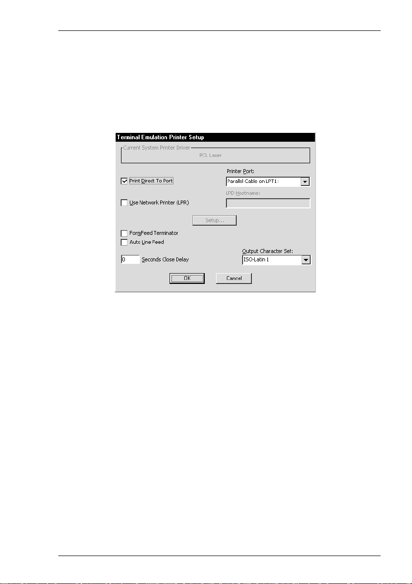
Setup Menus
3. Click the OK button to save the template settings. If you specified a descriptive
name that already exists, a message box will ask you to confirm whether or not
you want to overwrite the existing name with the new settings.
Printer Setup...
This will display a dialog box which enables you to specify print settings.
You can direct print data to a printer handled by the Print Manager, a specific port, or a
network printer.
Direct Print Data To The Print Manager
The Current System Printer Driver box displays the name of the currently selected
system printer when both the Use Network Printer (LPR) and Print Direct To Port
options are not selected.
Clicking the Setup button will display a Print Manager dialog box which enables you
to specify printer settings.
If you find a through print results in data being split into lines, each treated as a
separate print job, specify a time in the Seconds Close Delay box (e.g. 5 seconds).
This will enable the next line of data to be sent before the print job is assumed to have
finished and therefore prevents the print job from being closed prematurely. When set
to 0, printing will not start until a ‘print end of job’ command is received from the
host. Entering any other number will cause printing to start after the specified number
of seconds have elapsed, regardless of whether the ‘print end of job’ command has
been received from the host.
6-11
Page 72

Setup Menus
Direct Print Data To A Specific Port
To direct print data to a specific port, select Print Direct To Port and specify the
Printer Port.
Selecting the FormFeed Terminator option will cause the printer to advance the
paper to the top of the form when it has finished printing.
The Output Character Set option enables you to specify the character set used for
printing when Print Direct To Port is selected. This allows non-ISO Latin-1 printers
to be used.
Selecting Auto Line Feed will cause the printer to print at the beginning of the next
line when a carriage return command is received.
When a serial port is selected, clicking the Setup button will display a dialog box in
which you can specify the baud rate, parity, flow control, data bits and stop bits
settings. These options are described in the Serial Settings section.
Direct Print Data To A Network Printer
To direct print data to a printer on the network, select Use Network Printer (LPR)
and enter the LPD Hostname. Clicking the Setup button will display a dialog box
which enables you to specify various print settings.
6-12
Page 73

Setup Menus
You must specify the Printer Name. The Job Name and User Name entries are
optional (the User Name will default to root if none is specified). You can specify
how many times the LPR protocol will attempt to execute the print job before
cancelling by setting the number of Retries and the number of seconds delay between
each attempt. When Add Banner is selected, information about this print job will be
printed with it. You can display a message box which will indicate the progress of the
print job by selecting Debug Information.
Print Screen
This will perform a print screen.
Print Buffer
This will send a copy of all the data contained in the window buffer to the currently
selected printer.
Auto Print
This toggles auto print mode on and off, as indicated by a tick when auto print mode is
on. Auto print mode causes each line of data to be transmitted to the printer when the
cursor moves to a new line as a result of a carriage return, line feed, vertical tab, or
form feed.
Cancel Print
This will cancel the current Print Screen or Print Buffer function.
Eject Page
This option enables data that has been spooled to the printer to be printed.
Exit
This option will cause the emulator to shut down.
6-13
Page 74
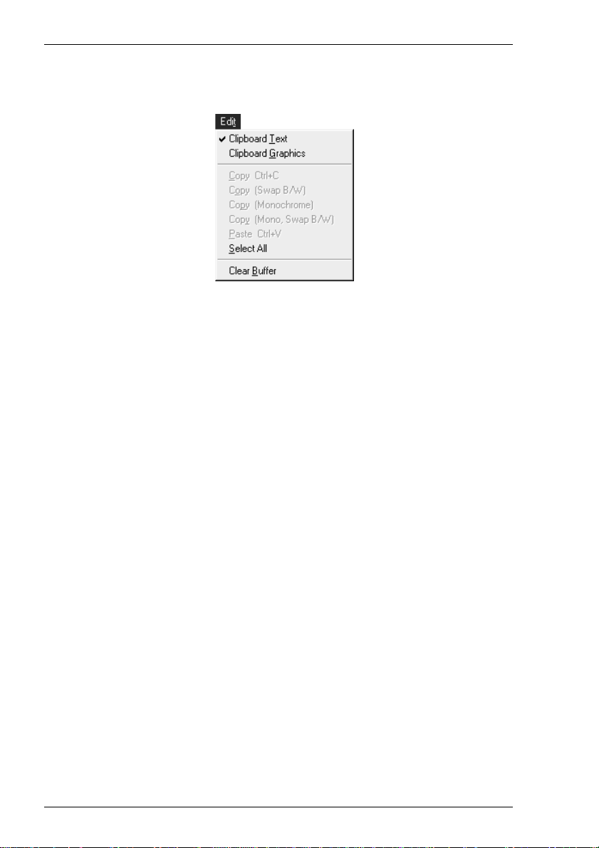
Setup Menus
Edit Menu
Clipboard Text
Clipboard Graphics
Selecting one of these options will enable selected text or graphics to be copied to the
clipboard when the Copy command is used. The Paste and Select All commands will
also be enabled. A tick will be displayed next to the option when it is selected.
Copy
The Copy commands become available when data has been selected. They will cause
the currently selected text or graphics to be copied to the clipboard. The data can then
be inserted in a different position or another file using the Paste command. The next
block of data that is copied will delete the previous block on the clipboard.
The first Copy option enables you to perform a standard copy. The last three options
are only available when Clipboard Graphics is selected. They enable you to copy the
graphics image with black and white reversed, with colour converted to monochrome,
or both.
Paste
This will cause data that has been copied to the clipboard to be pasted at the current
cursor position. The same block of data may be pasted repeatedly as the clipboard
stores it until the Copy command is used again.
Select All
This will cause the window contents (not the entire buffer) to be selected.
Clear Buffer
This will erase the contents of the window and the scroll buffer.
6-14
Page 75

Setup Menus
Settings Menu
Language
This enables you to select the language that will be used in all menus and dialog boxes.
The following dialog boxes can be displayed from this menu. Note that the dialog
boxes used to configure specific emulations can only be displayed when the relevant
emulation is running.
Emulation Settings - for specifying the terminal emulation.
HP 700-92/96 Settings - for configuring the HP 700-92/96 emulation.
IBM 3151 Settings - for configuring the IBM 3151 emulation.
Wyse Settings - for configuring the Wyse 50/50+/60, TVI 910+/
920/925, ADDS A2 and HZ 1500 emulations.
TA 6530 Settings - for configuring the Tandem 6530 emulation.
IBM 3270 Settings - for configuring the IBM 3270 emulation.
IBM 5250 Settings - for configuring the IBM 5250 emulation.
Serial Settings - for specifying serial communication settings.
Auxport Settings - for specifying auxilliary port settings.
Terminal Settings - for specifying terminal and display settings.
Local Editing - for specifying DEC VT Block (Edit) mode local
editing functions.
6-15
Page 76

Setup Menus
Block Transmission - for specifying DEC VT Block (Edit) mode text
formatting and transmission.
Attributes - for assigning colours and specifying how
characters with attributes are displayed.
Keyboard Macros - for redefining the function of keys.
Soft Buttons - for defining soft button functions.
Mouse Button Actions - for defining mouse functions.
Button Tools - for defining buttons on the toolbar.
6-16
Page 77

Setup Menus
Emulation Settings
This dialog box is displayed by selecting Emulation in the Settings menu.
Alpha Emulation
(Not available in WBT mode)
The setting of this option determines the current alpha emulation mode.
The ADDS A2 emulation provides compatibility with software designed to drive the
ADDS Viewpoint A2 terminal, as emulated by the Wyse WY-50/50+/60 terminals.
Refer to the Wyse Emulations chapter for details.
The AIXTerm emulation provides compatibility with software designed to drive an X
terminal using X Windows.
The Ansi BBS emulation is a derivative of the ANSI device driver ANSI.SYS
supplied with all DOS based PCs and which provides the screen management for the
DOS console screen. PC based UNIX systems and Bulletin Board Systems (BBS)
often rely on the ANSI emulation when being accessed by a PC. In ANSI BBS mode
the screen size is adjusted to 25 lines and the Preferred Char. Set option in the
Terminal Settings dialog box is automatically set to Ansi. The setting of the Ansi
Code Page option in this dialog box determines the characters available in the ANSI
BBS set.
The AT 386 emulation provides compatibility with software designed to drive the
AT&T AT 386 terminal.
The DG 410/412 emulation provides compatibility with software designed to drive the
Data General D410 and D412 terminals. Refer to the DG 410/412 Emulation chapter
for details.
6-17
Page 78

Setup Menus
The HP 700-92/96 emulation provides compatibility with software designed to drive
the Hewlett Packard 700/92, 2392A, 2622A, 70094 and 70096 terminals. This
emulation is described in detail in the HP 700-92/96 Emulation chapter.
The HZ1500 emulation provides compatibility with software designed to drive the
Hazeltine 1500 terminal, as emulated by the Wyse WY-50/50+/60 terminals. Refer to
the Wyse Emulations chapter for details.
The IBM 3151 emulation provides compatibility with software designed to drive the
IBM 3151 terminal. Refer to the IBM 3151 Emulation chapter for information on this
emulation.
The IBM 3270 emulation provides compatibility with software designed to drive the
IBM 3270 terminal. Note that the initial display will be an ASCII text screen known as
Network Virtual Terminal mode (NVT mode for short). The setting of the IBM 3270
Model option in the IBM 3270 Settings dialog box determines the size of the display
and whether or not extended attributes are supported. Refer to the IBM 3270
Emulation chapter for details.
The IBM 5250 emulation provides compatibility with software designed to drive IBM
5250 type alphanumeric terminals. This emulation can be used for connection to an
IBM AS/400, System/36 or System/38. Note that the initial display will be an ASCII
text screen known as Network Virtual Terminal mode (NVT mode for short). Refer to
the IBM 5250 Emulation chapter for details.
SCO Console is an emulation of the SCO UNIX box.
The TA6530 emulation provides compatibility with software designed to drive the
Tandem 6530 terminal. This emulation is described in the TA6530 Emulation chapter.
The TVI 910, TVI 920 and TVI 925 emulations provide compatibility with software
designed to drive the TeleVideo 910, 920 and 925 terminals, respectively, as emulated
by the Wyse WY-50/50+/60 terminals. Refer to the Wyse Emulations chapter for
details.
The TVI 950 and TVI 955 emulations provide compatibility with software designed
to drive the TeleVideo 950 and 955 terminals, respectively.
The VT52 and VT100 emulations enable you to run applications written for the DEC
VT52 and VT100 terminals, respectively. Refer to the DEC VT Emulations chapter for
details.
The VT500 7-Bit and VT500 8-Bit emulations enable you to run applications written
for the DEC VT320 terminal, the difference is in their treatment of 8-bit control codes.
When VT500 7-Bit is selected, all 8-bit codes are converted to their 7-bit equivalents,
whereas VT500 8-Bit leaves 8-bit codes unchanged. If you are using VT200
applications, select VT500 7-Bit. Refer to the DEC VT Emulations chapter for details.
The VT PCTerm emulation provides compatibility with software designed for the PC
Term mode supported by DEC. This is the same as the VT510 emulation except that
keyboard scan codes are sent on key press/release instead of ASCII codes by default.
6-18
Page 79

Setup Menus
The WYSE PCTerm emulation provides compatibility with software designed for the
PC Term personality supported by Wyse. Keyboard scan codes are sent on key press/
release instead of ASCII codes by default.
The WY50, WY50+ and WY60 emulations provide compatibility with software
designed to drive the Wyse WY-50, WY-50+ and WY-60 terminals, respectively.
Refer to the Wyse Emulations chapter for information on these emulations.
VT Terminal ID
Factory default: VT420
This specifies what is reported back to the host in response to a terminal identification
request. You can either select from the list of IDs or you can edit the text box and enter
a different terminal identity. (Note that not all features of the specified terminal may be
supported.)
National
Factory default: Unselected
This will only be available if the system is configured for a language that supports
national replacement character sets.
The setting of this option determines the type of character set used to generate
characters. When selected, a character set specific to the selected keyboard nationality
is used. When unselected (default) the emulator is in Multinational mode, a character
set consisting of two tables of characters is used. This enables characters from any
keyboard nationality to be generated.
Tertiary Device Attribute
When the emulator is in VT420 mode (Emulation set to VT500 and Terminal ID set
to VT420), this option enables you to specify the tertiary device attribute report that is
sent in response to a request from the host.
Answerback String
This option enables you to specify the Answerback string that is sent to the host in
response to an ANSI mode enquiry command. The string may be up to 30 characters
long.
Answerback Concealed
Factory default: Unselected
Selecting this option will cause the Answerback string specified in the text box above
to be locked from change and displayed as asterisks. Note that deselecting this option
will cause the Answerback string to be deleted.
6-19
Page 80

Setup Menus
HP 700-92/96 Settings
This dialog box is displayed by selecting HP 700-92/96 in the Settings menu.
Local Echo
Factory default: Unselected
The setting of this option determines whether keyboard entered characters are
displayed on the screen as well as sent to the host. When unselected, characters are not
displayed when they are transmitted to the host unless the host 'echoes' them back.
Caps Lock
Factory default: Unselected
This determines whether the full 128-character ASCII range can be generated, or only
Teletype-compatible codes.
When this option is unselected, all 128 ASCII characters can be generated. When
selected, unshifted alphabetic keys will generate their shifted equivalents. For example,
the A key unshifted will generate an uppercase A, and the {, | and } keys will generate
[, \, and ], respectively. The key for generating ~ and ` is disabled.
XmitFnctn (A)
Factory default: Unselected
This option determines whether escape sequences generated by control and function
keys are sent to the host or only to the terminal emulation.
When unselected, escape sequences are only sent to the terminal emulation. When
selected, escape sequences are sent to the host. If the Local Echo option is selected, the
sequences will also be sent to the terminal emulation.
6-20
Page 81

Setup Menus
SPOW (B)
Factory default: Unselected
The setting of the SPace OverWrite option determines whether or not keyboard
entered spaces overwrite existing characters. When unselected, keyboard entered
spaces will overwrite existing characters.
Selecting this option will cause the SPOW latch to be enabled. The latch can then be
activated by a carriage return. When activated, keyboard entered spaces will cause the
cursor to move forward without deleting characters that already exist. The latch can be
deactivated by a tab, line feed or home-up command. This will cause spaces to
overwrite existing characters as normal.
InhEolWrp (C)
Factory default: Unselected
The Inhibit End of line Wrap option determines whether characters wrap to the next
line when the right margin is reached. When selected (i.e. inhibited), on reaching the
right margin, the last character position will be overwritten with every new character
received until a carriage return or other cursor movement command is issued.
LineTx (D)
Factory default: Unselected
The setting of this option determines whether data is sent a line or a page at a time
when in Edit mode.
When this option is selected, data will be transmitted a line at a time. When unselected,
data will be transmitted a page at a time. Page data will either be from the beginning of
display memory or from the current cursor position.
InhHndShk (G)
InhDC2 (H)
Factory default: Unselected
The combined setting of these two options determine the type of handshaking used
when blocks of data are transmitted to the host.
One of three types of handshake may be used:
1. No handshake. Blocks of data are sent immediately when the relevant transmit key
is pressed.
2. DC1 handshake. Data is only sent to the host when the host sends an ASCII DC1
control code to request it.
3. DC1/DC2/DC1 handshake. The host sends an ASCII DC1 control code, to which
the emulator replies by sending a DC2 code if ready to transmit. The host sends
the DC1 code again to cause the data block to be transmitted.
6-21
Page 82

Setup Menus
The type of handshake used for block transfers is determined by the type of block
transfer to be performed, the mode that the HP 700-92/96 emulation currently
operating in (character, block line, block page, or modify mode), and the setting of
these two options.
The setting of these two options will have the following general effect:
InhHndShk only selected:
The DC1/DC2/DC1 handshake or no handshake will be used.
InhDC2 only selected:
The DC1 handshake or no handshake will be used.
InhHndShk and InhDC2 selected:
No handshake will be used.
Enq/Ack Pacing
Factory default: Selected
The setting of this option determines whether the Hewlett Packard ENQ ACK
handshake is used or not. When selected, the host can send an ASCII ENQ (enquiry)
control code at the end of transmission asking if the data has been processed, to which
the emulator will reply by sending an ACK (acknowledge) code when it has. Note that
this form of handshaking has the lowest priority after hardware and XON/XOFF
handshaking.
EscXfer
Factory default: Unselected
This option determines whether escape sequences relating to the display are sent when
the display memory is transferred to the printer.
When unselected, escape sequences relating to the display are not sent to the printer.
When selected, each line transferred to the printer will begin with an escape sequence
to select the primary character set and stop any character enhancements. When escape
sequences relating to the display are encountered within the data (for example, to
change the character set), they will be sent to the printer.
Destructive Backspace
Factory default: Unselected
The setting of this option determines whether or not pressing the Backspace key will
cause characters to be deleted.
CR = CR/NULL
Factory default: Unselected
This option must only be selected if you are going to use the QEDIT application. It
overcomes a bug within QEDIT that ignores the LF character if the terminal transmits
6-22
Page 83

Setup Menus
CR/LF. Inserting a NULL after the CR character cures the problem.
Display Form Feeds
Factory default: Selected
When selected, this will cause form feeds to be represented on the display as
characters.
Ignore Form Feeds
Factory default: Unselected
When the emulator receives a form feed command from the host it normally results in
a line feed on the display in HP 700-92/96 mode. Selecting this option will cause the
emulator to ignore all form feed commands received from the host.
Return Def
Factory default: ^M (i.e. CR)
This enables you to define the function of the Return key. Up to two characters may
be used to define the key. If a second character is a space, it will be ignored.
To change the current definition, delete the definition displayed in the text box and
type in the new one, either as the control key character equivalent or the decimal value
of the ASCII character.
For example, the default code for the Return key function, CR (carriage return), can
be entered by typing the characters ^ and M, representing the keys Ctrl + M which,
when pressed together would generate the CR code.
Decimal values are entered as three-digit numbers immediately preceded by an
underscore character. Values with only two digits must be preceded by a zero. For
example, the decimal value of CR is 13, so this would be entered as _013. Refer to the
ASCII character table in the Character Sets appendix for code and decimal references.
F
F
Start Column
Factory default: 1
This text box is used to specify the start column for transmitted data when no logical
start-of-text pointer is present and the Return or Enter keys are pressed in Modify
Line or Modify All mode.
Usually a start-of-text pointer is automatically generated to designate the leftmost
character in the current line if it is the last line of data in display memory. This pointer
will remain in display memory until the line is deleted. If the line has no start-of-text
pointer, data transmission will begin at the start column specified by this option. The
column range is from 1 to 80 inclusive.
Note: The setting of this option may be temporarily redefined using
one of the Margin/Tab/Col function keys. See the HP 70092/96 Emulation chapter for details.
6-23
Page 84

Setup Menus
FldSeparator
Factory default: ^_ (i.e. US)
This text box is used to specify the ASCII character used to indicate the end of each
protected field (except the last) that is sent in Edit Mode.
To change the current definition, delete the definition displayed in the text box and
type in the new one, either as the control key character equivalent or the decimal value
of the ASCII character. For example, the default ASCII character US can be entered by
typing the characters ^ and _, representing the keys Ctrl + _ which, when pressed
together would generate the US code.
Decimal values are entered as three-digit numbers immediately preceded by an
underscore character. Values with only two digits must be preceded by a zero. For
example, the decimal value of US is 31, so this would be entered as _031. Refer to the
ASCII character table in the Character Sets appendix for code and decimal references.
BlkTerminator
Factory default: ^^ (i.e. RS)
This text box is used to specify the ASCII character sent to the host to indicate the end
of a data block transmission.
To change the current definition, delete the definition displayed in the text box and
type in the new one, either as the control key character equivalent or the decimal value
of the ASCII character. For example, the default ASCII character RS can be entered by
typing the character ^ twice, representing the keys Ctrl + ^ which, when pressed
together would generate the RS code.
Decimal values are entered as three-digit numbers immediately preceded by an
underscore character. Values with only two digits must be preceded by a zero. For
example, the decimal value of RS is 30, so this would be entered as _030. Refer to the
ASCII character table in the Character Sets appendix for code and decimal references.
Terminal ID
Factory default: 70092
This specifies what is reported back to the host in response to a terminal identification
request. (Note that not all features of the specified terminal may be supported.)
Clicking the arrow button will display a drop-down list box showing the available
settings, 70092, 2392A, 2622A, 70094 or 70096. If you are using the keyboard, press
the up or down arrow keys until the setting required is displayed. You can either select
from this list or enter a different terminal identity in the text box.
6-24
Page 85

Setup Menus
Pages
Factory default: 4
In HP 700-92/96 mode the display area is 80 or 132 columns by 24 lines with 168
lines stored off-screen, giving a total display memory of 192 lines. This option enables
you to specify whether display memory is divided into 2, 4, 6 or 8 pages.
Typeahead Enabled
Factory default: Unselected
When the emulator is connected to an HP 3000, you normally have to wait for the host
to send a prompt before you can enter new data at the keyboard, otherwise the data is
ignored. Selecting this option will enable you to type continuously without waiting for
the prompt. Data is stored in the keyboard buffer and each time the emulator receives a
prompt it will send a line of data to the host. Block mode also supports typeahead.
Host Prompt Character
Factory default: ^Q (i.e. DC1)
Some hosts send a prompt character to the terminal to indicate that they are ready to
receive the next line or block of data. This option enables you to specify the prompt
character for your particular host. Most hosts either use the DC1 (^Q) character (e.g.
HP 3000) or no prompt (^@) character.
When Typeahead Enabled is selected, the emulator will wait for the specified prompt
character from the host before transmitting the next line from the keyboard buffer.
6-25
Page 86

Setup Menus
IBM 3151 Settings
This dialog box is displayed by selecting IBM 3151 in the Settings menu.
Operating Mode
Factory default: Echo
The setting of this option determines how keyboard entered data is sent to the host and
displayed on the screen.
In Echo mode, keyboard entered data is sent only to the host. The host is then
responsible for returning the data to the display.
In Character mode, keyboard entered data is sent simultaneously to the host and the
display.
In Block mode, keyboard entered data is displayed and processed locally, allowing
you to edit it before a block of data is sent to the host.
Row and Column
Factory default: 24 x 80
This option enables you to select one of four display formats:
24 rows x 80 columns
25 rows x 80 columns
24 rows x 132 columns
25 rows x 132 columns
6-26
Page 87

Setup Menus
Note that the contents of the display will be cleared when you change the display
format.
Turnaround Char
Factory default: CR
This option specifies the line turnaround character (LTC) that is generated when a
Read command is received or one of the block data transmission keys is pressed. Note
that selecting DC3 will disable the XON/XOFF inbound and outbound pacing
characters.
Forcing Insert
Factory default: Both
This option specifies how an insert command affects displayed data when the screen is
full.
When set to Off, you will not be able to perform an insert operation.
When set to Line, you will be able to insert one or more lines, using the Ins Ln key for
example. The contents of the current and all following lines will move down the
number of lines inserted, causing the lines originally at the bottom of the display to be
discarded.
When set to Character, you will be able to insert one or more characters in the current
line. Characters to the right of the cursor position will move along. If the Auto Wrap
option is set to No, then characters originally at the end of the current line will be
discarded. If set to Yes, characters on all following lines will move along, forcing
characters at the end of the last line to be discarded.
When set to Both, the function of the Line and Character settings will be enabled.
Insert Character
Factory default: Space
The setting of this option determines the effect of pressing the Insert key.
When set to Space, a space character will be inserted after the current cursor position.
When set to Mode, the emulation will enter Insert mode when the Insert key is
pressed.
Tab Operation
Factory default: Field
The setting of this option determines whether tab stops are according to field attribute
characters or column-tab definitions.
When set to Field, tab stops in a formatted page are provided by field attribute
characters. Column-tab definitions are ignored.
6-27
Page 88

Setup Menus
When set to Column, tab stops are provided by column-tab definitions. Field attribute
characters are ignored.
Enter Key
Factory default: Return
This option enables you to specify whether the Enter key performs the same function
as the Return key or the Send key.
Return Key
Factory default: Field
This option specifies whether or not the cursor can enter a line within a protected field
when the Return key is pressed.
When set to Field, the result of pressing the Return key is determined by the setting of
the Auto New Line option and the cursor will move to the next unprotected line.
When set to New Line, the result of pressing the Return key is determined by the
setting of the Auto New Line option.
Send Operation
Factory default: Page
The setting of this option determines the effect of pressing the Send and Send Line
keys.
When set to Page, the contents of the current page will be sent to the host when Send
is pressed, or the current line if Send Line is pressed.
When set to Line, the contents of the current line will be sent to the host when Send is
pressed, or the current page if Send Line is pressed.
Auto Wrap
Factory default: Selected
The setting of this option determines what happens to the cursor and data sent to the
display when the end of the current line is reached.
When selected, the cursor will automatically move to the beginning of the next line.
Note that this will always be the case in block mode or in a formatted page regardless
of the setting of this option.
When unselected, the cursor will remain at the end of the current line and each new
character sent to the display will overwrite the character already occupying the cursor
position.
6-28
Page 89

Setup Menus
Auto LF
Factory default: Unselected
The setting of this option in conjunction with that of the Auto New Line option
determines the destination of the cursor when the Return key is pressed or the CR
character is received.
When both this and the Auto New Line options are unselected, the cursor will move
to the first position of the current line when the Return key is pressed or the CR
character is received.
When this is unselected and Auto New Line is selected, the cursor will move to the
first position of the next line when the Return key is pressed.
When this is selected and Auto New Line is unselected, the cursor will move to the
first position of the next line when the Return key is pressed or the CR character is
received.
When both this and the Auto New Line options are selected, the cursor will move to
the first position of the line after the next line when the Return key is pressed.
Auto New Line
Factory default: Unselected
The setting of this option determines the effect of pressing the Return key.
When unselected, the Return key will generate a CR (carriage return) character.
When selected, the Return key will generate a CR and an LF (line feed) character.
Terminal ID
Factory default: Unspecified
This specifies what is reported back to the host in response to a terminal identification
request. The terminal ID can be up to 20 characters long. (Note that not all features of
the specified terminal may be supported.)
Model
Factory default: 11
This option identifies the terminal model being emulated in response to a terminal
identification request from the host. Model 11 supports only one viewport containing
24 or 25 rows and 80 columns. Model 31 supports up to three viewports (80 or 132
columns wide) and pass-through printing.
6-29
Page 90
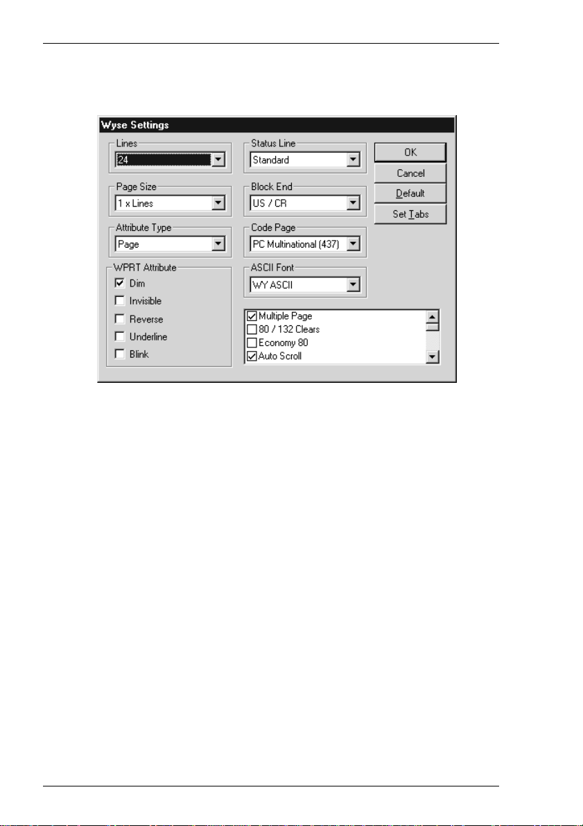
Setup Menus
Wyse Settings
This dialog box is displayed by selecting Wyse in the Settings menu. Note that some
of the settings apply to the TVI 910+, TVI 920, TVI 925, ADDS A2 and HZ 1500
emulations in addition to the Wyse emulations. Also, some settings may not apply to
the particular Wyse emulation currently running. Selecting a setting that is not
applicable to the current emulation will cause the emulator to use the default setting for
that emulation when the dialog box is exited.
Note: The Tab Stops dialog box displayed by clicking the Set Tabs
button is described later in this chapter, after the Terminal
Settings description.
Lines
Factory default: 24
This option applies to the WY-50+ and WY-60 emulations and specifies the number
of data lines displayed on the screen below the status line. Note that the other
emulations only support 24 lines and a label line.
24 24 data lines and a label line at the bottom.
25 25 data lines but no label line.
42 42 data lines and a label line at the bottom.
43 43 data lines but no label line.
6-30
Page 91

Setup Menus
Page Size
Factory default: 1 x Lines
This option applies to the WY-50+ and WY-60 emulations and specifies the size of a
page in display memory in multiples of the Lines setting. Note that the other
emulations only support 1 x Lines.
The 1 + Rest setting will divide the display memory into two pages, the first
containing the number of lines specified by the Lines option, the second containing all
the remaining lines.
Note that changing the page format will cause the entire display memory to be cleared,
the cursor will move to the home position and the scroll margin will be reset.
Status Line
Factory default: Standard
This option applies to all emulations and enables you to specify the type of status line
displayed at the top of the screen, or remove it from the display.
Both the Standard and Extended status lines display messages about the state of the
emulation or application. The Extended status line displays additional editing status
messages. Refer to the Wyse Emulations chapter for details.
Block End
Factory default: US / CR
This option applies to all emulations and specifies the ASCII characters used to
indicate the end of a line and a block when a block of data is sent to the host.
When set to US / CR, the line terminator is a US character and the block terminator is
a CR character. When set to CRLF / ETX, the line terminators are the CR and LF
characters, and the block terminator is an ETX character.
Attribute Type
Factory default: Page
The setting of this option determines whether display attributes are active to the end of
the line or the end of the page. The Character setting only applies to the WY-60
emulation and causes attributes to only apply to characters written to the screen. The
WY-50, ADDS A2 and HZ 1500 emulations only support the Page setting.
Code Page
Factory default: PC Multinational 437
This option determines the set of characters that form the second half of the
multinational character set when in multinational mode (as set by the Character Set
Mode option in the Emulation Settings dialog box).
6-31
Page 92

Setup Menus
ASCII Font
Factory default: WY ASCII
This option determines whether the Wyse ASCII or PC standard character set is used
as the first half of the multinational character set when in multinational mode (as set by
the Character Set Mode option in the Emulation Settings dialog box).
WPRT Attribute
Factory default: Dim
This option applies to all emulations and enables you to specify the appearance of
write-protected characters on the display. They can be displayed in reverse video,
dimmed or blinking. The WY-50+ and WY-60 emulations also support the underline
and invisible attributes.
Multiple Page
Factory default: Unselected
This option applies to the WY-50+, WY-60 and all the TVI emulations. It determines
whether or not more than one page of display memory can be accessed. When selected,
all pages will be accessible. See also the Auto Page option.
Note that the TVI emulations support two pages of 24 lines each when this and the
Auto Page options are selected, regardless of the Lines and Page Size settings.
80 / 132 Clears
Factory default: Unselected
This option applies to the WY-50+ and WY-60 emulations and determines whether or
not data is cleared from the display when the number of columns is changed. The
screen is always cleared when the number of columns is changed in the other
emulations.
Economy 80
Factory default: Unselected
This option applies to the WY-50+ and WY-60 emulations and enables 80 column
display with more lines of display memory.
Auto Scroll
Factory default: Selected
This option applies to all emulations and determines what happens when the cursor is
moved beyond the last line of the current page. When selected, the displayed data
scrolls up and the cursor remains on the last line. When unselected, the cursor moves to
the top of the same page.
6-32
Page 93

Setup Menus
Auto Page
Factory default: Unselected
This option applies to the WY-50+, WY-60 and all the TVI emulations. It determines
what happens when the cursor reaches the top or bottom of the page.
When unselected, the cursor either moves to the top of the same page or data scrolls up
from the bottom, as determined by the setting of the Auto Scroll option. When
selected, a new page of memory will be displayed.
Note: The other emulations will always display a new page of
memory.
Auto Wrap
Factory default: Selected
The setting of this option determines whether characters wrap to the next line when the
right margin is reached. When unselected, on reaching the right margin, the last
character position will be overwritten by every new character received.
DEL = DestBS
Factory default: Unselected
This option applies to the WY-50+ and WY-60 emulations and determines what effect
an ASCII DEL character has on displayed characters. The other emulations ignore the
DEL character.
When unselected, the DEL character is ignored. When selected, the DEL character is
interpreted as a destructive backspace, causing the character to the left of the cursor to
be deleted and the cursor to move into that position.
Margin Bell
Factory default: Unselected
This option applies to all emulations and specifies whether or not an audible warning
sounds when the cursor reaches a specified column. The default bell column number is
72 in 80 column mode and 124 in 132 column mode.
Enhance
Factory default: Selected
When this option is selected, the emulator will recognize an additional set of Wyse
codes which are not normally supported by specific non-Wyse terminals.
Answerback Mode
Factory default: Unselected
This option applies to all emulations and specifies whether or not an answerback
message is automatically sent to the host in response to an ASCII ENQ character.
6-33
Page 94

Setup Menus
Send ACK
Factory default: Selected
This option applies to all emulations and specifies whether or not an ASCII ACK
character is sent to the host port after certain commands have been executed.
Block Mode
Factory default: Unselected
This option applies to all emulations. In Block mode, keyboard entered data is
displayed and processed locally, allowing you to edit it before a block of data is sent to
the host. When Block mode is disabled, data is sent to the host as it is entered at the
keyboard.
Colour Support
Factory default: Unselected
When this option is selected, an additional set of host commands will be recognized to
determine the colours used for the display. Wyse 350 colour commands will be
recognized in all modes except Wyse 60, which will use Wyse 60 colour commands.
Application Key Mode
Factory default: Unselected
When application key mode is selected, the function keys and certain editing keys will
send application codes when pressed, regardless of whether or not the keys have been
redefined. When this option is not selected, the keys will send their programmed
definitions.
CR=CR/NULL
Factory default: Selected
This option allows you to disable the NULL being automatically sent on CR.
6-34
Page 95

Setup Menus
T A6530 Settings
This dialog box is displayed by selecting TA 6530 in the Settings menu.
Power On Mode
Factory default: Conversational
This option determines the operating mode that is in effect when the TA6530
emulation is entered.
Note: Changing the current setting will not take effect until you re-
load the emulation, so you will need to save the new setting
before exiting the emulation.
Conversational and Block modes are normally used for applications running on a
NonStop host system, and ANSI mode for applications running on an LXN host
system. Save the new setting before exiting the emulation by selecting Save Session in
the File menu.
Packet Block
Factory default: OFF
This option specifies whether you want to use packet blocking for X.25 communica-
tions line support, and if so, the size of the packet block. The size may be set to any of
the listed 128-byte increments, or, by setting this option to OFF, the default size of
260 bytes.
Status Border
Factory default: Selected
This option enables you to display a thin border which separates the status line from
the rest of the lines on the display.
6-35
Page 96

Setup Menus
Telserv Format
Factory default: Selected
The setting of this option determines how network data is treated. When selected, data
will be treated in Tandem network server (Telserv) format. When unselected, data will
be treated in serial format.
Return Function
Factory default: Unselected
This option specifies whether or not the function of the Enter key is defined by the
application when in Block mode. When selected, the key is regarded as an application
specific function key. Normally this should be unselected.
Bell On
Factory default: Selected
This option enables or disables an audible tone which is heard when the emulation
warns you about something. This needs to be selected when you want to use the Bell
Column feature.
Bell Column
Factory default: 0
This option enables you to specify a particular column on the display which will cause
an audible warning to sound when the cursor passes through it.
The valid range of column numbers is 1 to 80. Setting this option to 0 will disable the
feature. The Bell On option must be selected for this feature to work.
6-36
Page 97

IBM 3270 Settings
Setup Menus
This dialog box is displayed by selecting IBM 3270 in the Settings menu.
IBM 3270 Model
Factory default: 3278-2-E
This specifies what is reported back to the host in response to a terminal identification
request. (Note that not all features of the specified terminal may be supported.)
TN3287 printing is supported by selecting 3287-1.
One of four display sizes can be selected:
3278/9-2 24 rows by 80 columns
3278/9-3 32 rows by 80 columns
3278/9-4 43 rows by 80 columns
3278/9-5 27 rows by 132 columns
3278 settings with the E extension provide support for the following extended
attributes (these are supported by the 3279 as standard):
3270 Field Attributes
Extended Highlighting
Foreground Colour
Query Reply Inbound Structured Fields
6-37
Page 98

Setup Menus
Numeral Swap
Factory default: Unselected
When using a code page that supports a bilingual keyboard, this will cause all numbers
to be displayed using the National character set when in Latin mode.
Symbol Swap
Factory default: Unselected
Selecting this option will cause symbols such as brackets to be displayed the correct
way round when typing in right-to-left mode.
Rule Line
Factory default: Cross
A rule can be displayed across the emulation workspace at the cursor position by
pressing the keys Alt + Page Down, which toggles it on and off. The setting of this
option determines whether it is displayed as a horizontal rule, vertical rule or both.
Follows Cursor
Factory default: Unselected
When the rule is displayed in the emulation workspace, the setting of this option
determines whether or not the rule follows the cursor when it moves.
Notice Board Setup
This will display the Notice Board Setup dialog box as described in the next section.
Unlock Delay
Factory default: 0
This option is available when the IBM 3270 Model is not set to a printer. When the
keyboard is unlocked by the host, this specifies a delay in milliseconds before
characters are sent.
Print Bypass Character
This option is available when the IBM 3270 Model option is set to a printer. The
Start Seq box enables you to enter the character or sequence of characters that initiate
a print bypass.
The end sequence that terminates the print bypass can be specified either by entering
the actual characters in the End Seq box when Specify End Sequence is selected, or
by specifying the number of characters that make up the end sequence in the End
Length box when End on Non-Hex is selected.
If no End Seq is entered, the bypass is assumed to be for a single pair of characters
only. If an End Seq is specified, characters in the data stream between the start and end
are interpreted as encoded ASCII. For example, “1B0A” becomes ASCII 27 10 (ESC
LF).
6-38
Page 99

Setup Menus
Selecting End on Non-Hex enables you to specify the number of characters that make
up the end sequence in the End Length box. The bypass will then terminate as soon as
a non-hexadecimal character is received (any character except in the range 0 through 9
and A through F) followed by the end sequence.
Characters can be entered in several ways. For example, to specify the ASCII escape
character, you can enter either _027, \u001B, \e, \033, or even ^[.
Font
This enables you to specify the font to be used for displaying characters. The available
settings depend on the fonts installed.
SBCS, APL2 & DBCS
The Single Byte Character Set, APL2 and Double Byte Character Set options enable
you to change the settings used by default for the chosen language. These should only
be changed by the System Administrator. If they have been changed and you wish to
restore the default settings in this dialog box, click the Default button. The following
table shows the default settings. A list of IBM EBCDIC codepages supplied can be
found at the end of the Character Sets appendix.
Note: Double byte character sets may not be supported by this
version of the emulator.
6-39
Page 100

Setup Menus
Default Language, Codepage & Character Set Settings
Language
English (US)
English (UK)
Belgian
Canadian French
Danish
Finnish
German
Dutch
Italian
Swiss French
Swiss German
Swedish
Norwegian
French
Spanish
Portuguese
Japanese Kanji + Katakana
Korean
Simplified Chinese
Traditional Chinese
Hebrew New Code
Hebrew Old Code
Thai
Greek
Cyrillic
Turkish
Russian
Czech
Slovak
Polish
Icelandic
Arabic
Type
SBCS
SBCS
SBCS
SBCS
SBCS
SBCS
SBCS
SBCS
SBCS
SBCS
SBCS
SBCS
SBCS
SBCS
SBCS
SBCS
SBCS
DBCS
SBCS
DBCS
SBCS
DBCS
SBCS
DBCS
SBCS
SBCS
SBCS
SBCS
SBCS
SBCS
SBCS
SBCS
SBCS
SBCS
SBCS
SBCS
Codepage
285
500
277
278
273
280
500
500
278
277
297
284
290
300
833
834
836
837
835
424
803
838
875
880
1026
1025
870
870
870
871
420
37
37
37
37
37
Char Set
697
697
697
697
697
697
697
697
697
697
697
697
697
697
697
697
1172
1001
1173
934
1174
937
1175
935
941
941
1176
925
960
1152
1150
959
959
959
697
697
CCSID
37
285
500
37
277
278
273
37
280
500
500
278
277
297
284
37
290
930
833
933
836
937
37
935
424
424
838
875
880
1026
1025
870
870
870
871
285
6-40
 Loading...