

Page 1

TL881 MiniLibrary Drive Upgrade Procedure
First Edition (May 1999)
Part Number ER-TL881-DA. A01/138248-001
Compaq Computer Corporation
Page 2

Notice
The information in this publication is subject to change without notice.
COMPAQ COMPUTER CORPORATION SHALL NOT BE LIABLE FOR TECHNICAL OR
EDITORIAL ERRORS OR OMISSIONS CONTAINED HEREIN, NOR FOR INCIDENTAL OR
CONSEQUENTIAL DAMAGES RESULTING FROM THE FURNISHING, PERFORMANCE, OR
USE OF THIS MATERIAL. THIS INFORMATION IS PROVIDED “AS IS” AND COMPAQ
COMPUTER CORPORATION DISCLAIMS ANY WARRANTIES, EXPRESS, IMPLIED OR
STATUTORY AND EXPRESSLY DISCLAIMS THE IMPLIED WARRANTIES OF
MERCHANTABILITY, FITNESS FOR PARTICULAR PURPOSE, GOOD TITLE AND AGAINST
INFRINGEMENT.
This publication contains information protected by copyright. No part of this publication may be
photocopied or reproduced in any form without prior written consent from Compaq Computer
Corporation.
© 1999 Compaq Computer Corporation.
All right s re served. Printed in the U.S.A.
The software described in this guide is furnished under a license agreement or nondisclosure agreement.
The software may be used or copied only in accordance with the terms of the agreement.
Com paq, Deskpro, Fastart , C ompaq In sight Manager, Systempro, Sy stempr o/LT, ProLia nt, ROMPaq,
QVision, SmartStart, NetFlex, QuickFind, PaqFax, ProSignia, registered United States Patent and
Trademark Office.
Neoserver, Netelligent, Systempro/XL, SoftPaq, QuickBlank, QuickLock are trademarks and/or service
marks of Compaq Computer Corporation.
Microsoft, MS -DO S, Win dow s, and Windows NT are registered trade ma rks of Microsoft Corp or at ion.
Pentium is a registered trademark and Xeon is a trademark of Intel Corporation.
Other product na me s ment ioned herein may be trad emarks and/or regist ered trademarks of the ir
respective companies.
TL881 MiniLibrary Drive Upgrade Procedure
First Edition (May 1999)
Part Number ER-TL881-DA. A01/138248-001
Page 3

Contents
About This Guide
Text Conventions.................................................................................................... v
Symbols in Text..................................................................................................... vi
Symbols on Equipment..........................................................................................vi
Rack Stability.......................................................................................................vii
Getting Help.........................................................................................................vii
Compaq Technical Support............................................................................vii
Compa q Website...........................................................................................viii
Compaq Authorized Reseller...........................................................................ix
Adding a Second Tape Drive
Parts Lo cation.........................................................................................................1
Overall Procedure...................................................................................................2
Removing and Replacing the Skin Cover (Desktop Models Only).....................3
Removing and Replacing the Cover Plate.........................................................4
Removing and Replaci n g the Drive Caddy Assem bly ....................................... 5
Installing the Second Tape Drive......................................................................7
Index
Page 4

iv TL881 MiniLibrary Drive Upgrade Procedure
List of Figures
Figure 1. Parts Location.........................................................................................1
Figure 2. Removing the Skin Cover........................................................................3
Figure 3. Removing the Cover Plate.......................................................................5
Figure 4. Drive Caddy Assembly Parts...................................................................6
List of Tables
Table 1 Parts Location............................................................................................2
Page 5

This guide is designed to be used as step-by-step instructions for installation
and as a reference for operation, troubleshooting, and future upgrades.
Text Conventions
This document uses the following conventions to distinguish elements of text:
Keys Keys appear in boldface. A plus sign (+) between
About This Guide
two keys indicates that they should be pressed
simultaneously.
USER INPUT
FILENAMES File names appear in uppercase italics.
Menu Options,
Command Names,
Dialog Box Names
COMMANDS,
DIRECTORY NAMES,
and DRIVE NAMES
Type When you are instructed to typ e information, type
Enter
User input appears in a different typeface and in
uppercase.
These el ements app ea r in initial capital lette r s .
These elements appear in uppercase.
the information without pressing the Enter key.
When you are instructed to enter information, type
the information and then press the Enter key.
Page 6
vi TL881 MiniLibrary Drive Upgrade Procedure
Symbols in Text
These symbols may be found in the text of this guide. They have the following
meanings.
WARNING:
in the warning could result in bodily harm or loss of life.
CAUTION:
could res ult in dam a g e to eq ui pme nt or los s of inf or m at io n.
IMPORTANT:
instructions.
NOTE:
Text set off in this manner presents commentary, sidelights, or in teresting points
of informa tion.
Text set off in this manner indicates that failure to follow directions
Text set off in this manner presents clarifying information or s pec ific
Symbols on Equipment
These icons may be located on equipment in areas where hazardous conditions
may exist.
Any surface or area of the equipment marked with these symbols
indicates the presence of electrical shock hazards. Enclosed area
contains no operator serviceable parts.
WARNING:
do not open this enclosur e.
Text set off in this manner indicates that failure to follow directions
To reduce the risk of injury fr om electrical shock hazards,
Any RJ-45 receptacle marked with these symbols indicates a Network
Interface Connection.
WARNING:
the equi pme nt , do no t pl u g tele ph on e or t elecommu nic a ti ons
connectors into this receptacle.
Any surface or area of the equipment marked with these symbols
indicates the presence of a hot surface or hot component. If this
surface is contacted, the potential for injury exists.
WARNING:
the surfac e to cool befor e touchin g.
To reduce the risk of electrical shock, fire , or damage to
To reduce the risk of injury fr om a hot component, allow
Page 7

Rack Stability
About This Guide vii
Power Supplies or Systems marked with these symbols
indicate the equipment is supplied by multiple sources of
power.
WARNING: To reduce the risk of injury from electrical shock,
remove all power cords to completely disconnect power from
the system.
WARNING: To reduce the risk of personal injury or dama ge to the equipment,
be sur e that:
■ The leveling jacks are extended t o the floor.
■
The full weight of the rack rests on the leveling jacks.
■
The stabilizing feet are attache d to the rack if it is a sing le rack
installations.
■
The racks are coupled together in multiple rack installations.
■
A rack may become unstable if more than one component is extended for
any reason. Extend only one component at a time.
Getting Help
If you have a problem and have exhausted the information in this guide, you
can get further information and other help in the following locations.
Compaq Technical Support
You are entitled to free hardware technical telephone support for your product
for as long you own the product. A technical support specialist will help you
diagnose the problem or guide you to the next step in the warranty process.
In North America, call the Compaq Technical Phone Support Center at
1-800-OK-COMPAQ
Outside North America, call the nearest Compaq Technical Support Phone
Center. Telephone numbers for world wide Technical Support Centers are
1
For continuous quality improvement, calls may be recorded or monitored.
1
. This service is available 24 hours a day, 7 days a week.
Page 8

viii TL881 MiniLibrary Drive Upgrade Procedure
listed on the Compaq website. Access the Compaq website by logging on to
the Internet at http://www.compaq.com.
Be sure to have the following information available before you call Compaq:
■
Technical support registration number (if applicable)
■
Product serial number (s)
■
Product model name(s) and numbers(s)
■
Applicable error messages
■
Add-on boards or hardware
■
Third-p arty hardwa re or so ftware
■
Operating system type and revision level
■
Detailed, specific questions
Compaq Website
The Compaq website has information on this product as well as the latest
drivers and Flash ROM images. You can access the Compaq website by
logging on to the Internet at http://www.compaq.com.
Page 9

Compaq Authorized Reseller
For the name of your nearest Compaq Authorized Reseller:
■
In the United States, call 1-800-345-1518.
■
In Canada, call 1-800-263-5868.
■
Elsewhere, see the Compaq website for locations and telephone
numbers.
About This Guide ix
Page 10

Adding a Second Tape Drive
IMPORTANT:
must
step, you might cause premature failure of the mechanism.
Parts Location
Figure 1 shows the location of most of the field replaceable parts. Table 1
describes the parts.
2
1
14
13
All screws that do not use lock washers, captive washers or lock nuts
have Loctite 222 applied when parts are reassembled in the field. If you ignore this
12
5
4
3
8
9
1011
6
7
SHR-1201
Figure 1. Parts Location
Page 11

2 TL881 MiniLibrary Drive Upgrade Procedure
(1) Magazine door
(2) Door opener/Magazine lock
(3) Shuttle cable
(4) Shuttle
(5) Shuttle motor
(6) Drive caddy assembly
(7) Fan
(8) Powe r supply
(9) Controller PWB
(10) AC power switch
Table 1
Parts Location
Number Part
(11) Control panel
(12) Unlock/open switch
(13) Magazine security lock
(14) Leadscrew
Overall Procedure
NOTE:
If the base module is part of an expanded TL881 MiniLibrary subsystem, refer to
the
TL881 Mini Library Service Manual
from the subsystem.
To add a second drive to the ba se modul e you must do t he foll owing ste ps.
1. Remove the skin cover, i f present , using t he proc e dure i n t his
document.
2. Remove the cover plate using the procedure in this document.
3. Remove the drive c addy a ssembl y using the proc edure i n thi s
document.
for information on removing the base module
Page 12

4. Install the new drive using the procedure described in this document.
5. Replace the drive caddy assembly.
6. Replace the cover plate.
7. Replace the skin cover.
Removing and Replacing the Skin Cover (Desktop
Models Only)
The skin cover is held in place by two screws on each side of the base
module (Figure 2).
Adding a Second Tape Drive 3
Figure 2. Removing the Skin Cover
Removing
Do these steps to remove the skin cove r from the ba se modul e .
1. Remove the two screws on each side of the base module.
2. Grasp the cover by the sides at the bottom edge and pull outwards
slightly while lifting the cover straight up and off the chassis.
Replacing
Do these steps to replace the skin cover on the base module.
SHR-1433
Page 13

4 TL881 MiniLibrary Drive Upgrade Procedure
1. Position the skin cover over the base module with the two angled
surfaces facing toward the front.
2. Slide the skin cover over the module until it touches the front panel.
3. Insert the two screws on each side through the skin cover into the base
module; insert and start all four screws before you tighten any of them.
Removing and Replacing the Cover Plate
Removing
Do these steps to remove the cover plate from the base module.
1. If the base module is a desktop model, remove the skin cover as
described in Removing and Re pl aci ng t he Sk i n Cove r (Desktop Mode ls
Only).
2. Disconnect the power and interface cables at the rear of the module.
3. Unscrew the captive screw in the center of the cover plate (Figure 3).
4. Slide the cover plate one-half inch toward the rear of the module.
5. Lift the cover plate off the base module.
Replacing
Do these steps to replace the cover plate on the base module.
1. Place the cover plate on the base module so that it overhangs one-half
inch at the rear of t he modul e (Figure 3).
2. Slide the cover plate toward the front of the base module until the
cover plate touches the front panel.
3. Tighten the captive screw in the center of the cover plate.
4. Connect the power and interface cables at the rear of the module.
5. If the base module is a desktop model, replace the skin cover as
described in Removing and Re pl aci ng t he Sk i n Cove r (Desktop Mode ls
Only).
Page 14
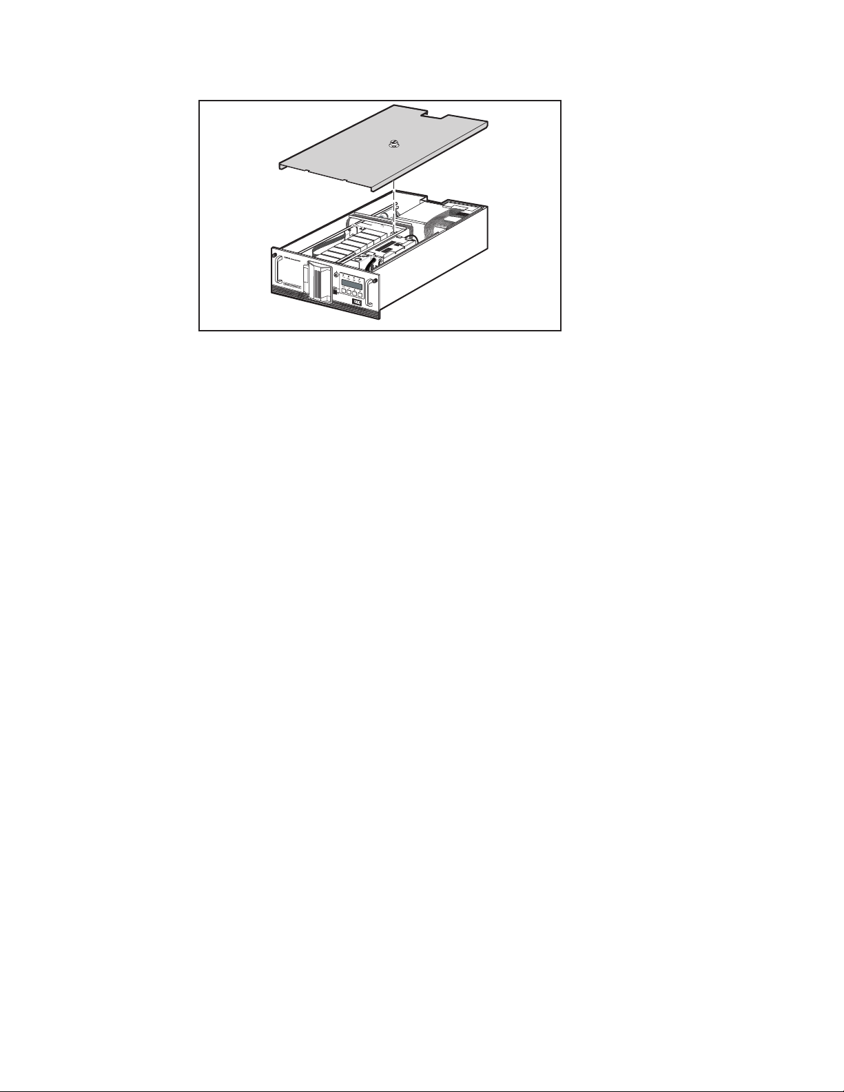
Figure 3. Removing the Cover Plate
Removing and Replacing the Drive Caddy Assembly
The drive caddy assembly i s an e ncl osure t hat hol ds one or two DLT dri ve s
and the interconnecting cables. The assembly includes the SCSI interface
connectors and cables for the ba se modul e , the power c abl e s for the dri ve s,
and communication cables from the drives to the controller PWB.
Adding a Second Tape Drive 5
SHR-1203
66
Removing
Do these steps to remove the drive c addy a ssembl y from t he base m odul e.
1. Remove the cover plate as described in Removing and Replacing the
Cover Plate.
2. Disconnect the SCSI cable connectors (1) ( Figure 4) from the
controller SCSI extension cable.
Page 15

6 TL881 MiniLibrary Drive Upgrade Procedure
5
7
4
7
2
1
5
3
6
4
SHR-1204
Figure 4. Drive Caddy Assembly Parts
3. Disconnect the drive power “Y” cable (2) from the power supply
connector.
4. Disconnect the drive 1 RS-422 cable (3) at the controller PWB end.
5. Remove two M4 x 8mm flat-he ad scre ws (4) along t he uppe r e dge of
the drive caddy assembly.
6. Remove two M4 extension screws (5) at the top of t he drive c addy
assembly.
CAUTION: If you’re not careful, you might break the door levers when you lift
the drive caddy assembly out of the base module in the next step. To prevent
this, steady the caddy so it cannot rock forward as it clears the platform when
you’re lifting it up, and do not allow the door levers to touch the strut across
the top of the base module.
Page 16

Adding a Second Tape Drive 7
7. Grasp the handle on top and li ft t he drive c addy a ssembl y out of t he
base module carefull y; be c a reful t he door l e vers don’t bum p a gai nst
the chassis crossbrace.
8. Set the drive caddy assembly on the work surface and install the
second tape drive as describe d i n Instal li ng t he Se c ond Tape Drive.
Replacing
Do these steps to replace the drive caddy assembly in the base module.
CAUTION:
the drive caddy assembly down in the base module. To prevent this, steady the
assem bly as you lower it by the handle so it cannot rock forward as it
approaches the platform, and do not allow the door levers to touch the strut
across the top of the chassis.
If you’re not careful, you might break the door levers when you set
1. Grasp the drive caddy assembly by t he ha ndl e a nd l ower it i nto
position in the base module; orient it as shown in Figure 4, and be
careful the door levers don’t bump against the chassis crossbrace.
2. Replace the two M4 extension screws (5) at the top of the assembly
3. Coat the threads of the two M4 x 8mm flat-head Phillips screws (4)
with Loctite 222, and replace them on the upper edge of the drive
caddy assembly.
4. Connect the drive 1 and drive 2 RS-422 cables (3) to the controller
PWB.
5. Connect the drive power cable (2) to the power supply connector.
6. Connect the SCSI cable connectors (1) to the controller SCSI extension
cable.
7. Replace the cover plate as described in Removing and Replacing the
Cover Plate.
Page 17

8 TL881 MiniLibrary Drive Upgrade Procedure
Installing the Second Tape Drive
Do the following steps to install the second tape drive.
1. Remove the four 6-32 sems pan-head Phillips screws (7) that hold the
blank panel in place in the drive caddy assembly; there are two on the
top of the assembly (Figure 4) and two on the bot tom of t he a ssembl y.
2. Slide the blank pane l out of t he dri ve ca ddy a ssembly.
3. Disconnect the RS-422 cable toward the front on the top of the drive,
and lift the cable clear of the cable clamps; set it aside.
4. Install the door lever on the flatted shaft at the bottom of the drive.
5. Slide the drive (6) into the drive caddy assembly; position the drive so
the threaded holes in the top and bottom of the drive are aligned with
the screws holes.
6. Install the four 6-32 sems pan-head Phillips screws that were removed
in Step 1.
7. Connect the unused connector on the power Y-cable to the drive just
installed.
8. Connect the unused connector on the SCSI cable to the drive just
installed.
9. Install the RS-422 cable supplied with the kit, sliding it under the
clamps so that the connector is adjacent to the connector on top of the
new drive.
10. Install the RS-422 cable removed in Step 3 over the top of the new RS-
422 cable so that the connector is adjacent to the connector on top of
the original drive.
11. Connect the RS-422 cables to the connectors on the top of the drives,
through the holes in the top of t he drive c addy a ssembl y.
12. Replace the drive caddy assembly as described in Removing and
Replacing the Drive Caddy Assembly.
Page 18

B
base module 2
C
Index
Compaq website viii
Compq authorized resellers,
telephone numbers viii
technical support telephone
numbers vii
http://www.compaq.com viii
CAUTION
door levers 6
Compaq authorized reseller viii
cover plate 2, 4
D
drive 1 RS-422 cable 6
drive caddy assembly 2, 5
drive power "Y" cable 6
F
Field replaceable parts 1
G
getting help vii
H
help
additional sources vii
I
icons
symbols on equipment vi
L
Loctite 222 1
O
Overall Procedure 2
P
power and interface cables 4
R
RJ-45 receptacle vi
Page 19

2 TL881 MiniLibrary Drive Upgrade Procedure
S
SCSI cable connectors 5
second tape drive 7
skin cover 2
symbols in text vi
symbols on equipment vi
T
Table 1 Parts Location 2
technical support viii
telephone numbers viii
text conventions v
W
warnings
electrical shock vii
rack stability vii
www.compaq.com. viii
 Loading...