

Page 1

StorageWorks RAID Array 4000
User Guide
Fourth Edition (June 1999)
Part Number 241377-004
Compaq Computer Corporation
Page 2

Notice
The information in this publication is subject to change without notice.
COMPAQ COMPUTER CORPORATION SHALL NOT BE LIABLE FOR TECHNICAL OR
EDITORIAL ERRORS OR OMISSIONS CONTAINED HEREIN, NOR FOR INCIDENTAL OR
CONSEQUENTIAL DAMAGES RESULTING FROM THE FURNISHING, PERFORMANCE, OR
USE OF THIS MATERIAL. THIS INFORMATION IS PROVIDED “AS IS” AND COMPAQ
COMPUTER CORPORATION DISCLAIMS ANY WARRANTIES, EXPRESS, IMPLIED OR
STATUTORY AND EXPRESSLY DISCLAIMS THE IMPLIED WARRANTIES OF
MERCHANTABILITY, FITNESS FOR PARTICULAR PURPOSE, GOOD TITLE AND AGAINST
INFRINGEMENT.
This publication contains information protected by copyright. No part of this publication may be
photocopied or reproduced in any form without prior written consent from Compaq Computer
Corporation.
© 1999 Compaq Computer Corporation.
All rights reserved. Printed in the U.S.A.
The software described in this guide is furnished under a license agreement or nondisclosure agreement.
The software may be used or copied only in accordance with the terms of the agreement.
Compaq, Deskpro, Fastart, Compaq Insight Manager, Systempro, Systempro/LT, ProLiant, ROMPaq,
QVision, SmartStart, NetFlex, QuickFind, PaqFax, ProSignia, registered United States Patent and
Trademark Office.
Neoserver, Netelligent, Systempro/XL, SoftPaq, QuickBlank, QuickLock are trademarks and/or service
marks of Compaq Computer Corporation.
Microsoft, MS-DOS, Windows, and Windows NT are registered trademarks of Microsoft Corporation.
Pentium is a registered trademark and Xeon is a trademark of Intel Corporation.
Other product names mentioned herein may be trademarks and/or registered trademarks of their
respective companies.
Compaq StorageWorks RAID Array 4000 User Guide
Fourth Edition (June 1999)
Part Number 241377-004
Page 3
Contents
About This Guide
Text Conventions.........................................................................................................ix
Symbols in Text............................................................................................................x
Symbols on Equipment.................................................................................................x
Rack Stability...............................................................................................................xi
Getting Help.................................................................................................................xi
Compaq Technical Support..................................................................................xi
Compaq Website..................................................................................................xii
Compaq Authorized Reseller ..............................................................................xii
Chapter 1
Introduction
Features..................................................................................................................... 1-3
Front Panel Features ................................................................................................. 1-4
Rear Panel Features .................................................................................................. 1-5
Hot-Pluggability........................................................................................................ 1-6
Hot-Pluggable Drives ............................................................................................... 1-7
Maximum Storage..................................................................................................... 1-7
SCSI ID Assignments............................................................................................... 1-8
Compaq StorageWorks RA4000 Controller............................................................. 1-9
Features.............................................................................................................. 1-9
Hard Drive Arrays...........................................................................................1-10
Fault Tolerance................................................................................................ 1-10
Capacity Expansion......................................................................................... 1-11
Array Accelerator............................................................................................ 1-11
Performance Monitoring ................................................................................. 1-12
Automatic Performance Tuning ...................................................................... 1-12
Tagged-Command Queuing ............................................................................ 1-13
System Power.................................................................................................. 1-13
Redundant Power Supply Option ........................................................................... 1-13
Page 4

iv Compaq StorageWorks RAID Array 4000 User Guide
Chapter 2
Installation
Materials Needed.......................................................................................................2-1
Installing the Compaq StorageWorks........................................................................2-3
RAID Array 4000......................................................................................................2-3
Choosing a Location for an RA4000 Tower .............................................................2-4
Choosing a Location for a Rack-Mountable RA4000...............................................2-4
Installing the RA4000 Tower....................................................................................2-4
Installing the Rack-Mountable RA4000....................................................................2-5
Environment ..............................................................................................................2-6
Space Requirements ...........................................................................................2-6
Power Requirements...........................................................................................2-6
Grounding...........................................................................................................2-7
Temperature Requirements ................................................................................2-8
Airflow Requirements........................................................................................2-9
Blanking Panels..................................................................................................2-9
Installation ...............................................................................................................2-10
Installing the Rack-Mountable RA4000 ..........................................................2-10
Installing the Hot-Pluggable Hard Drives...............................................................2-14
Installing the Storage Hub.......................................................................................2-16
Installing the Storage Hub 7.............................................................................2-16
Installing the Storage Hub 12...........................................................................2-17
Installing a Compaq Fibre Host Adapter in a Server ..............................................2-18
Fibre Channel Cables...............................................................................................2-18
Single-Mode Fibre Channel Cable...................................................................2-18
GBIC Option Kit ..............................................................................................2-19
Multi-Mode Fibre Channel Cable ....................................................................2-19
Cable Installation Considerations............................................................................2-20
Rack-Mountable Systems.................................................................................2-20
Tower System..........................................................................................................2-21
Connecting the Power..............................................................................................2-22
Chapter 3
Operation
Applying Power.........................................................................................................3-1
LEDs..........................................................................................................................3-1
Front Panel..........................................................................................................3-2
Power Supply......................................................................................................3-3
Fan Assembly.....................................................................................................3-5
Hard Drives ........................................................................................................3-6
Page 5
Chapter 4
Troubleshooting
Interpreting Component LEDs ................................................................................. 4-1
Hard Drive LEDs............................................................................................... 4-2
Fibre Host Adapter LEDs.................................................................................. 4-3
RA4000 Controller LEDs.................................................................................. 4-4
Fibre Channel Storage Hub LEDs..................................................................... 4-6
Fan Assembly.................................................................................................... 4-9
Power Supply................................................................................................... 4-10
Replacing Components........................................................................................... 4-11
Replacing the RA4000 Controller without RA4000 Redundant Controller... 4-11
Replacing the RA4000 Controller with Redundant Controller....................... 4-13
Replacing the RA4000 Controller Cache........................................................ 4-15
Replacing GBICs............................................................................................. 4-18
Removing Fibre Channel Cables..................................................................... 4-19
Replacing the Power Supply ........................................................................... 4-19
Replacing the Fan Assembly........................................................................... 4-22
Replacing Hard Drives .................................................................................... 4-24
Chapter 5
Installing the Redundant Power Supply Option
Preparing the RA4000 .............................................................................................. 5-1
Installation ................................................................................................................ 5-2
About This Guide v
Chapter 6
Running the Array Configuration Utility
Before You Begin..................................................................................................... 6-2
Starting the Array Configuration Utility .................................................................. 6-2
Accessing Online............................................................................................... 6-3
SmartStart and Support Software CD................................................................ 6-3
Configuration Wizards.............................................................................................. 6-4
Getting Help.............................................................................................................. 6-4
Configuration Procedures......................................................................................... 6-5
Create a New Array........................................................................................... 6-5
Step 1: Choosing a Controller for the Array ..................................................... 6-6
Step 2: Grouping physical drives of the same size into an array ...................... 6-8
Step 3: Creating Logical Drives...................................................................... 6-11
Capacity Expansion......................................................................................... 6-13
Capacity Extension.......................................................................................... 6-16
Online Migration ............................................................................................. 6-18
Redundant Controllers..................................................................................... 6-20
Page 6
vi Compaq StorageWorks RAID Array 4000 User Guide
Running the Array Configuration Utility
continued
Array Configuration Utility Screens........................................................................6-21
Main Configuration Screen..............................................................................6-21
Controller Settings Screen................................................................................6-26
Create Array Screen .........................................................................................6-27
Create Logical Drive Screen ............................................................................6-29
Error and Warning Messages ..................................................................................6-31
NetWare Online Array Configuration Utility (CPQONLIN)..................................6-31
Auto-configuration...........................................................................................6-32
Custom Configuration......................................................................................6-33
Handling Disk Drive Failures...........................................................................6-37
Optimizing Array Controller Performance ......................................................6-38
Chapter 7
Options ROMPaq
Running the Procedure ..............................................................................................7-1
Appendix A
Regulatory Compliance Notices
Regulatory Compliance Identification Numbers......................................................A-1
Federal Communications Commission Notice.........................................................A-1
Modifications.....................................................................................................A-2
Cables ................................................................................................................A-2
Canadian Notice (Avis Canadien)............................................................................A-2
European Union Notice ............................................................................................A-2
Japanese Notice ........................................................................................................A-3
Taiwanese Notice......................................................................................................A-3
Laser Devices............................................................................................................A-3
Laser Safety Warnings ......................................................................................A-3
Compliance with CDRH Regulations ...............................................................A-4
Compliance with International Regulations......................................................A-4
Laser Product Label...........................................................................................A-4
Laser Information..............................................................................................A-4
Battery Replacement Notice.....................................................................................A-5
Appendix B
Electrostatic Discharge
Grounding Methods..................................................................................................B-2
Page 7

About This Guide vii
Appendix C
Specifications
RA4000 (Tower).......................................................................................................C-1
RA4000 (Rack-mountable).......................................................................................C-2
Appendix D
Fibre Channel Technology
Fibre Channel Standards...........................................................................................D-1
Advantages of Fibre Channel ...................................................................................D-1
Fibre Channel and External Storage Systems...........................................................D-2
Point-to-Point Connection.................................................................................D-3
Arbitrated Loop .................................................................................................D-4
Structured Format for Data Transmission ................................................................D-8
Protocol Layers ..................................................................................................D-9
Appendix E
Hard Drive Arrays
The Drive Array........................................................................................................E-1
Drive Arrays ......................................................................................................E-4
Logical Drives ...................................................................................................E-4
Drive Array Benefits.................................................................................................E-5
Data Protection..................................................................................................E-5
Performance Enhancement.....................................................................................E-10
Distributing Data and Data Striping................................................................E-10
Array Accelerator............................................................................................E-12
Concurrent I/O Request Servicing...................................................................E-13
Optimized Request Management .................................................................... E-13
Expanding Storage Capacity...................................................................................E-14
Online Capacity Expansion.............................................................................E-16
Hard Drive Upgrades....................................................................................... E-16
Other Fault Management Features..........................................................................E-17
Auto Reliability Monitoring............................................................................E-17
Dynamic Sector Repairing ..............................................................................E-17
Drive Parameter Tracking ............................................................................... E-17
Drive Failure Alert Features............................................................................E-18
Interim Data Recovery.....................................................................................E-18
Automatic Data Recovery ...............................................................................E-18
Page 8

viii Compaq StorageWorks RAID Array 4000 User Guide
Appendix F
Recovering From Hard Drive Failure
Recognizing a Drive Failure..................................................................................... F-1
Fault Tolerance and Drive Failure............................................................................ F-2
Non-Fault-Tolerant (RAID 0) Logical Drive.................................................... F-2
RAID 1 (Mirroring) Logical Drive ................................................................... F-2
Spare Drives ...................................................................................................... F-3
Replacing a Failed Drive.......................................................................................... F-4
Automatic Data Recovery................................................................................. F-4
Automatic Data Recovery Failure..................................................................... F-5
Compromised Fault Tolerance ................................................................................. F-5
Index
Page 9
This guide is designed to be used as step-by-step instructions for installation
and as a reference for operation, troubleshooting, and future upgrades.
Text Conventions
This document uses the following conventions to distinguish elements of text:
Keys Keys appear in boldface. A plus sign (+) between
USER INPUT User input appears in a different typeface and in
FILENAMES File names appear in uppercase italics.
About This Guide
two keys indicates that they should be pressed
simultaneously.
uppercase.
Menu Options,
Command Names,
Dialog Box Names
COMMANDS,
DIRECTORY NAMES,
and DRIVE NAMES
Type When you are instructed to type information, type
Enter When you are instructed to enter information, type
These elements appear in initial capital letters.
These elements appear in uppercase.
the information without pressing the Enter key.
the information and then press the Enter key.
Page 10
x Compaq StorageWorks RAID Array 4000 User Guide
Symbols in Text
These symbols may be found in the text of this guide. They have the following
meanings.
WARNING:
in the warning could result in bodily harm or loss of life.
CAUTION:
could result in damage to equipment or loss of information.
IMPORTANT:
instructions.
NOTE:
Text set off in this manner presents commentary, sidelights, or interesting points
of information.
Text set off in this manner indicates that failure to follow directions
Text set off in this manner indicates that failure to follow directions
Text set off in this manner presents clarifying information or specific
Symbols on Equipment
These icons may be located on equipment in areas where hazardous conditions
may exist.
Any surface or area of the equipment marked with these symbols
indicates the presence of electrical shock hazards. Enclosed area
contains no operator serviceable parts.
WARNING:
do not open this enclosure.
To reduce the risk of injury from electrical shock hazards,
Any RJ-45 receptacle marked with these symbols indicates a Network
Interface Connection.
WARNING:
the equipment, do not plug telephone or telecommunications
connectors into this receptacle.
To reduce the risk of electrical shock, fire, or damage to
Page 11
About This Guide xi
Any surface or area of the equipment marked with these symbols
indicates the presence of a hot surface or hot component. If this
surface is contacted, the potential for injury exists.
Rack Stability
WARNING:
the surface to cool before touching.
WARNING:
be sure that:
n The leveling jacks are extended to the floor.
n The full weight of the rack rests on the leveling jacks.
n The stabilizing feet are attached to the rack, if it is a single rack
installation.
n The racks are coupled in multiple rack installations.
n A rack may become unstable if more than one component is extended for
any reason. Extend only one component at a time.
To reduce the risk of injury from a hot component, allow
Power Supplies or Systems marked with these symbols
indicate the equipment is supplied by multiple sources of
power.
WARNING:
remove all power cords to completely disconnect power from
the system.
To reduce the risk of personal injury or damage to the equipment,
To reduce the risk of injury from electrical shock,
Getting Help
If you have a problem and have exhausted the information in this guide, you
can get further information and other help in the following locations.
Compaq Technical Support
You are entitled to free hardware technical telephone support for your product
for as long you own the product. A technical support specialist will help you
diagnose the problem or guide you to the next step in the warranty process.
Page 12
xii Compaq StorageWorks RAID Array 4000 User Guide
In North America, call the Compaq Technical Phone Support Center at
1-800-OK-COMPAQ
Outside North America, call the nearest Compaq Technical Support Phone
Center. Telephone numbers for world wide Technical Support Centers are
listed on the Compaq website. Access the Compaq website by logging on to
the Internet:
http://www.compaq.com
Be sure to have the following information available before you call Compaq:
n Technical support registration number (if applicable)
n Product serial number(s)
n Product model name(s) and numbers(s)
n Applicable error messages
n Add-on boards or hardware
n Third-party hardware or software
n Operating system type and revision level
n Detailed, specific questions
Compaq Website
1
. This service is available 24 hours a day, 7 days a week.
The Compaq website has information on this product as well as the latest
drivers and Flash ROM images. You can access the Compaq website:
http://www.compaq.com
Compaq Authorized Reseller
For the name of your nearest Compaq Authorized Reseller:
n In the United States, call 1-800-345-1518.
n In Canada, call 1-800-263-5868.
n Elsewhere, see the Compaq website for locations and telephone
numbers.
1
For continuous quality improvement, calls may be recorded or monitored.
Page 13

Chapter
Introduction
The Compaq StorageWorks RAID Array 4000 is a high-performance, external
system using various Fibre Channel devices and the Fibre Channel I/O
Standard to connect servers to external storage systems.
The Compaq StorageWorks RAID Array 4000 supports the following
components:
n Rack-mountable or Tower model Compaq RA4000
n Compaq RA4000 Controller (installed in the Compaq RA4000)
n Compaq StorageWorks Fibre Channel Storage Hub 7 or 12
n Fibre Channel cables
q Multi-mode for distances between 2 and 500 meters.
q Single-mode for distances of more than 500 meters and up to
10 kilometers
n GigaBit Interface Converter (GBIC) modules
q Shortwave GBICs for use with multi-mode cables
q Longwave GBIC for use with single-mode cables (optional)
n Hot-pluggable power supply
n Hot-pluggable Redundant Fan Assembly
n SmartStart and Support Software CD
Page 14
1-2
Compaq StorageWorks RAID Array 4000 User Guide
n Wide-Ultra SCSI-3, Fast-Wide SCSI, or Fast SCSI-2 hard drive support
n Redundant Hot-pluggable Power Supply (optional)
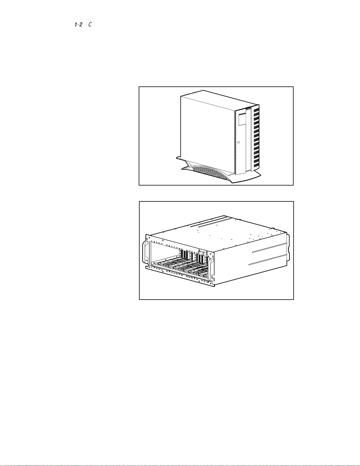
The Compaq StorageWorks RA4000 comes in either a rack-mountable or a
tower model, as shown in Figure 1-1 and Figure 1-2.
TROJ001.EPS
Figure 1-1. Compaq StorageWorks RA4000 (tower model)
TROJ002.EPS
Figure 1-2. Compaq StorageWorks RA4000 (rack-mountable model)
Page 15
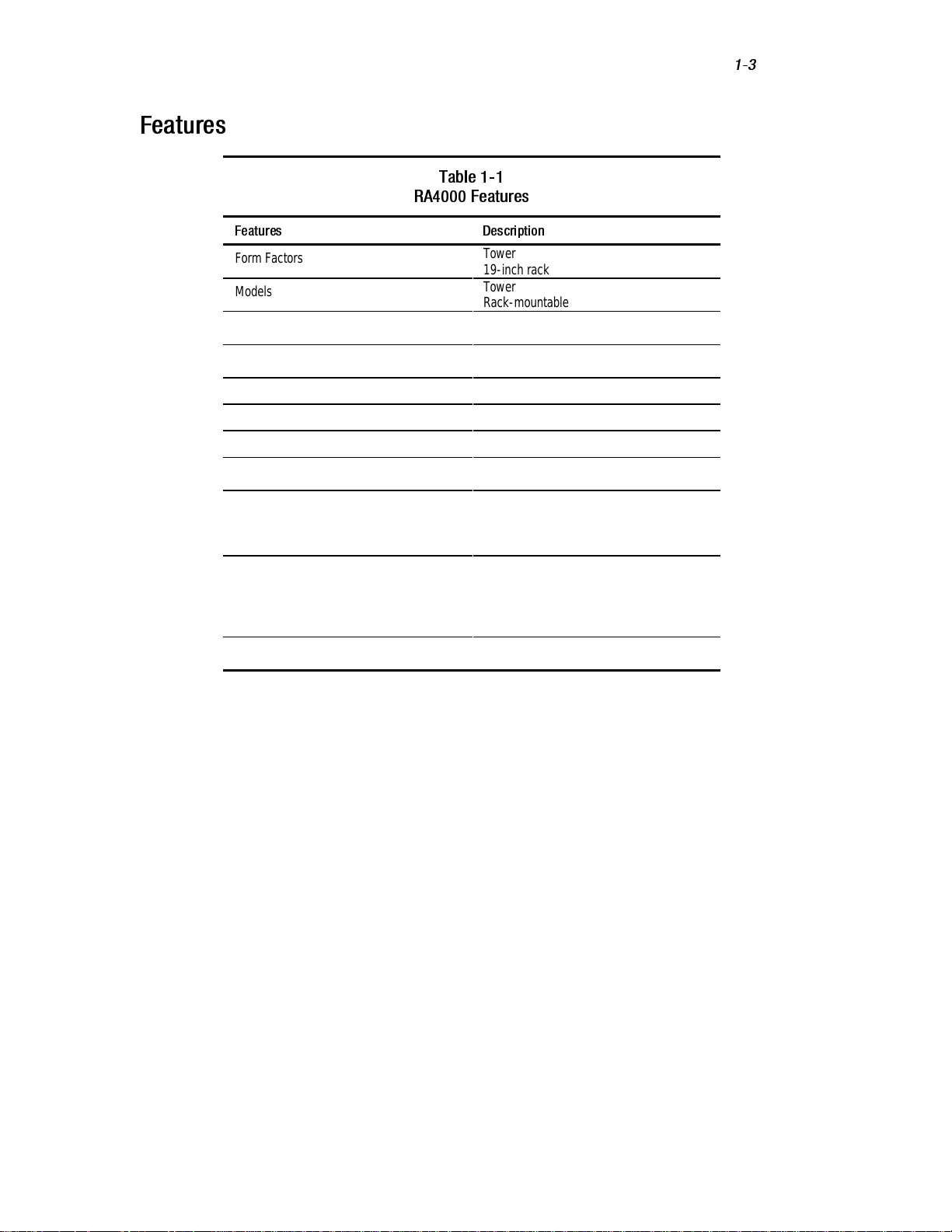
Features
Table 1-1
RA4000 Features
Features Description
Form Factors
Models
Controller
Maximum Number of Drives
Hard Drive Interface Wide-Ultra SCSI-3
Host Interface Fibre Channel Arbitrated Loop
SCSI ID Select Automatic
Options
Hot-Pluggable Components
LEDs
Warranty
Tower
19-inch rack
Tower
Rack-mountable
RAID 0, 1, 4, and 5
64-MB Read/Write Cache
12 (1-inch)
8 (1.6-inch)
Redundant Power Supply
Longwave GBIC
Drives
Fan Assembly
Power Supply (in redundant power supply
configurations)
Hard Drives
Storage System Front Panel
Fan Assembly
RA4000 Controller
Power Supply
Three-years parts and labor
On-site where available
Introduction
1-3
Page 16
1-4
Compaq StorageWorks RAID Array 4000 User Guide
Front Panel Features
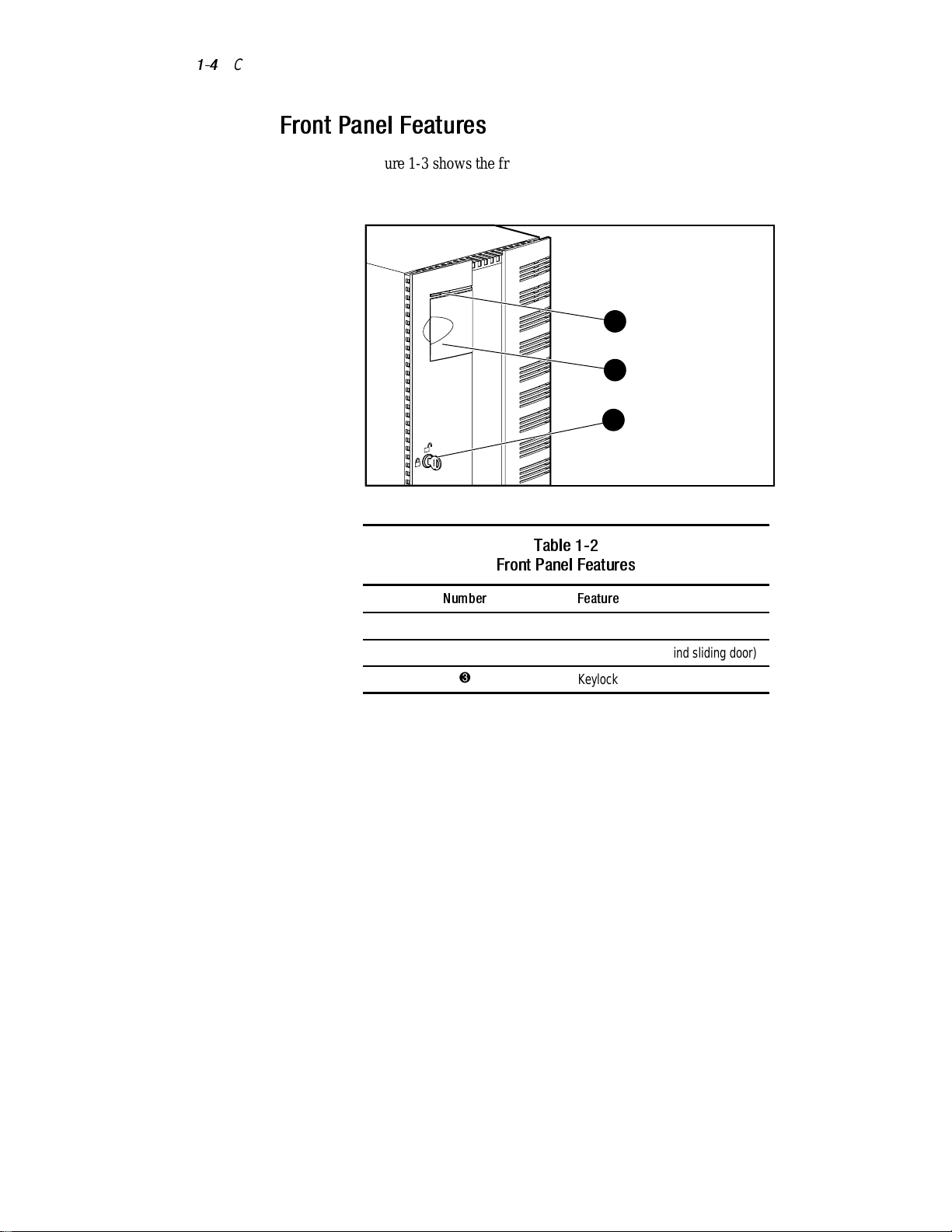
Figure 1-3 shows the front panel controls accessible to the user. The
rack-mountable model has the LEDs and power switch, but does not have a
plastic door.
Figure 1-3. Front panel feature (tower model shown)
1
2
3
Table 1-2
Front Panel Features
Number Feature
1
2
3
LEDs
Power switch (behind sliding door)
Keylock
Page 17
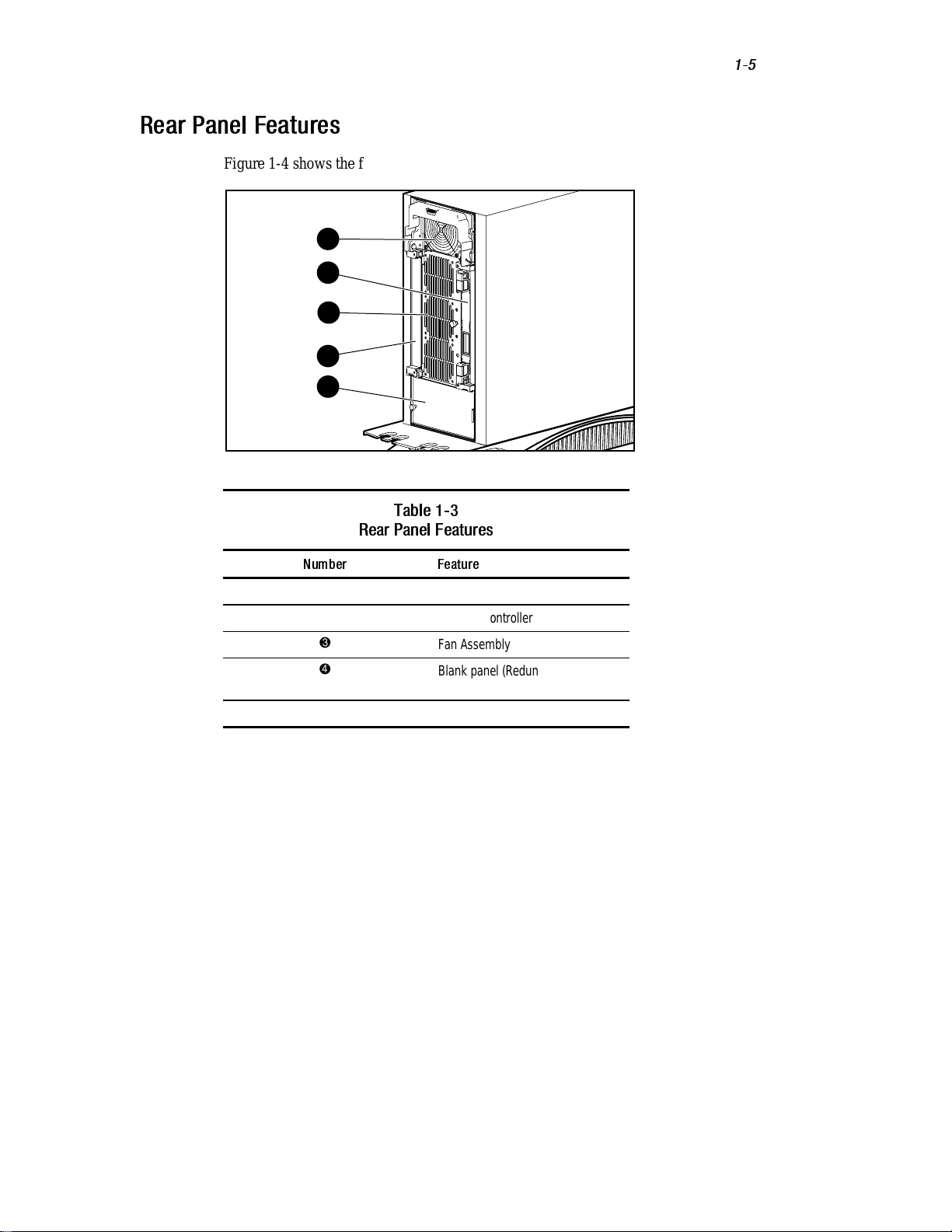
Rear Panel Features
Figure 1-4 shows the features and accessible components on the rear panel.
1
2
3
4
5
Figure 1-4. Rear panel features (tower model shown)
Table 1-3
Rear Panel Features
Introduction
1-5
Number Feature
1
2
3
4
5
Power supply
RA4000 Controller
Fan Assembly
Blank panel (Redundant RA4000
Controller)
Redundant power supply bay
Page 18

1-6
Compaq StorageWorks RAID Array 4000 User Guide
Hot-Pluggability
Hot-pluggability refers to the ability to remove and replace components
without powering down the system. There are four components in the Compaq
RA4000 that are considered hot-pluggable:
Hard Drives—Failed hot-pluggable drives in fault-tolerant configurations
RAID 1, 4, and 5 can be replaced without interrupting system operation. The
data on the failed drive will be restored automatically on the replacement drive
online.
Fan Assembly—If one of the cooling fans in the assembly should fail (the fan
LED is amber), the Fan Assembly can be removed and replaced. The fan
assembly must be replaced within five minutes to ensure system operation
continues without interruption.
Power supply—Only in systems with the optional redundant power supply
installed, either power supply may be removed and replaced without
interrupting system operation.
RA4000 Controller—If the failed RA4000 Controller cache is replaced with
the same size cache on the existing RA4000 Controller, the controller can be
removed, the cache replaced, and the controller reinstalled without interrupting
system operation. Changing the cache size requires that you power down the
system.
See Chapter 4, “Troubleshooting,” for specific limitations when replacing
hot-pluggable components.
Page 19
Hot-Pluggable Drives
The Compaq RA4000 supports these Compaq hot-pluggable drives:
n 1.6-inch Fast SCSI-2
n 1.6-inch Fast-Wide SCSI-2
n 1.6-inch Wide-Ultra SCSI-3
n 1-inch Fast SCSI-2
n 1-inch Fast-Wide SCSI-2
n 1-inch Wide-Ultra SCSI-3
The RA4000 accepts both 1-inch and 1.6-inch standard height drives. The
drives must be mounted on Compaq hot-pluggable drive trays. SCSI IDs are
assigned automatically according to the drive location, allowing 1-inch and
1.6-inch drives to be intermixed easily.
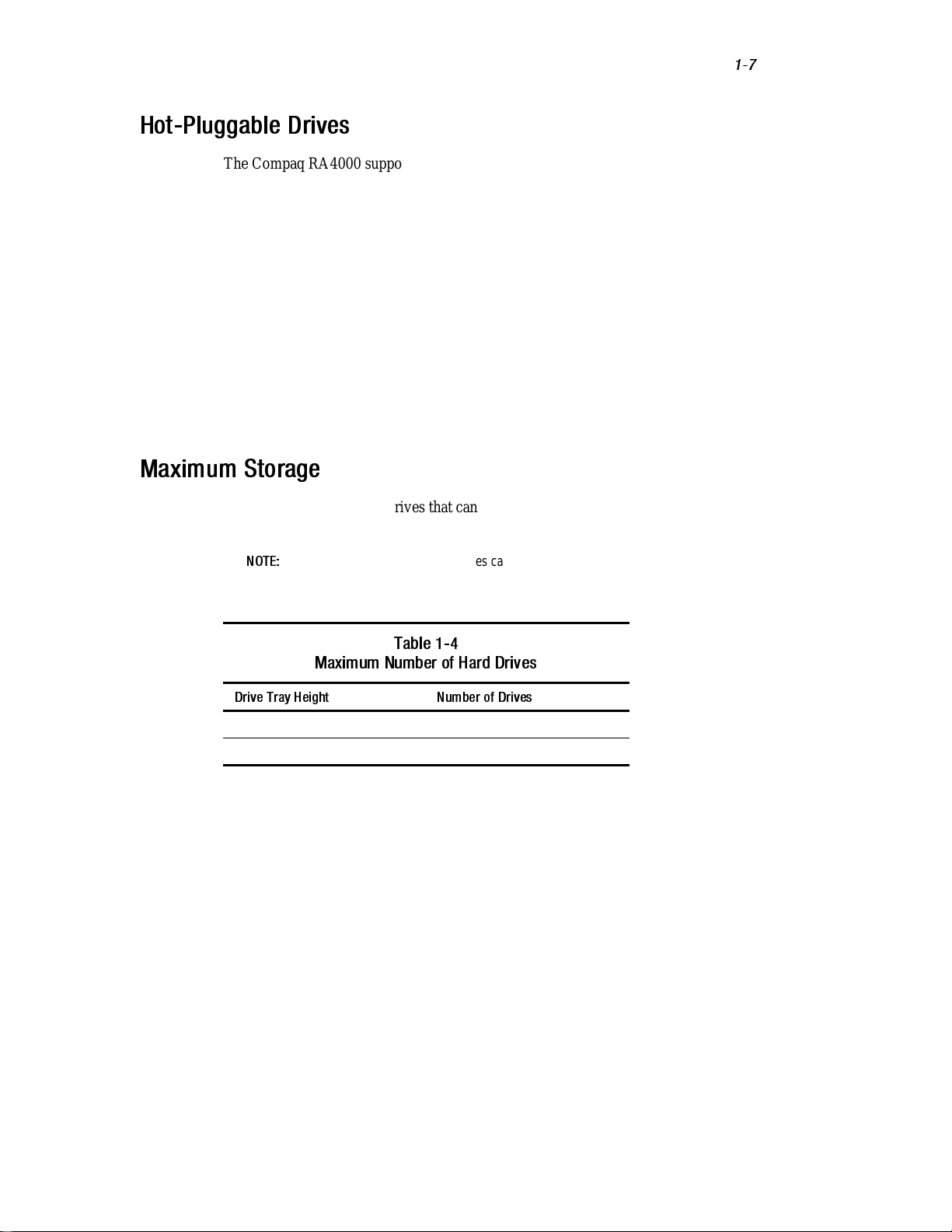
Maximum Storage
The maximum number of drives that can be installed in the Compaq RA4000
is shown in the table below.
Introduction
1-7
NOTE:
Both the 1-inch and 6-inch hard drives can be intermixed when installed in the
Compaq RA4000. To optimize capacity when intermixing drives, refer to the shadow
markings on the faceplate for appropriate 1-inch and 6-inch drive positions.
Table 1-4
Maximum Number of Hard Drives
Drive Tray Height Number of Drives
1-inch 12
1.6-inch 8
Page 20
1-8
Compaq StorageWorks RAID Array 4000 User Guide
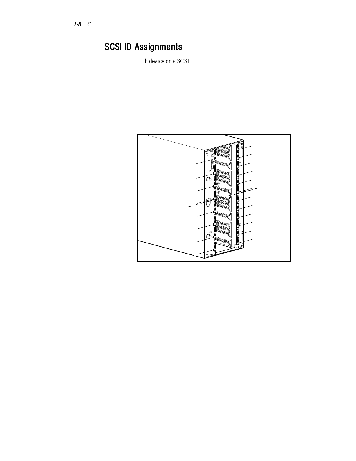
SCSI ID Assignments
Each device on a SCSI bus must have a unique identification number in the
range of 0 to 6. The SCSI ID determines the device priority when attempting
to use the SCSI bus. The highest priority, SCSI ID 7, is reserved for the
controller.
SCSI IDs are assigned automatically in the storage system according to the
drive bay used for each drive. It is not necessary to assign SCSI IDs manually.
The SCSI ID for each bay is indicated on the front panel.
The SCSI IDs assigned to drive bays in the Compaq StorageWorks RA4000
are shown in Figure 1-5.
Bus 2
SCSI ID's
1.6" Drives
Bus 1
5
4
3
2
1
0
5
4
3
2
1
0
Bus 2
Bus 1
SCSI ID's
1" Drives
4
3
1
0
4
3
1
0
Figure 1-5. SCSI ID numbering in the RA4000
TROJ006.EPS
Page 21
Compaq StorageWorks RA4000 Controller
The RA4000 Controller is a drive array controller designed for installation in
the RA4000. The RA4000 Controller supports Wide-Ultra SCSI-3, Fast-Wide
SCSI-2, and Fast SCSI-2. The RA4000 is equipped with one installed RA4000
Controller.
Features
The advanced features supported by the RA4000 Controller are:
n Support for RAID 0, 1, 4, and 5 fault-tolerance options
n Fibre Channel support for connection to the server
n Support for Wide-Ultra SCSI-3, Fast-Wide SCSI-2, and Fast SCSI-2
hard drives
n Online Capacity Expansion (Microsoft Windows NT and Novell
NetWare only)
n Online Volume Extension
n Online Stripe Size Migration
Introduction
1-9
n Online RAID Migration
n Removable RA4000 Controller Cache
n Battery-backed 64-MB Cache with ECC memory
n Controller board containing a 16-MB Read Cache
n Performance monitoring through Compaq Insight Manager
n Automatic performance tuning
n Pre-failure notification on hard disk drives
n Array Configuration Utility (ACU)
n Read-ahead caching
n Tagged-command queuing
n Multiple logical drives per RA4000
n Array Diagnostics Utility (ADU)
Page 22

1-10
Compaq StorageWorks RAID Array 4000 User Guide
Hard Drive Arrays
Drive array technology distributes data across a series of hard drives to unite
these physical drives into one or more higher performance logical drives.
Distributing the data makes it possible to access it concurrently from multiple
drives in the array, yielding faster I/O rates than nonarrayed drives. Each
logical drive in the array can be set to a different fault-tolerant configuration.
The RA4000 Controller manages the drive array independent of the host
processor.
There are several ways to configure each set of hardware. The Array
Configuration Utility is used to help you configure the hardware in the way
that best suits your needs. For more information on storage expansion, see
Appendix E, “Hard Drive Arrays.” See Chapter 6, “Running the Array
Configuration Utility,” for information on the Array Configuration Utility.
Fault Tolerance
Fault tolerance refers to several possible methods used to protect your system
from data loss in the event of a hardware failure somewhere in the storage
system. Each method has its advantages; choosing one requires careful
planning for your particular requirements.
The fault-tolerance methods supported by the RA4000 Controller and the
Compaq Array Configuration Utility include:
n Distributed data guarding (RAID 5)
n Data guarding (RAID 4)
n Drive mirroring (RAID 1)
n No fault tolerance (RAID 0)
Further data protection can be achieved by assigning an online spare to any
RAID 1, RAID 4, or RAID 5 configuration. For more information on the fault
tolerance settings, see Appendix E, “Hard Drive Arrays.”
Page 23
Capacity Expansion
Capacity Expansion refers to the ability to add storage capacity to an existing
array by adding hard drives.
The Array Configuration Utility lets you perform Capacity Expansion, even in
fault-tolerant configurations, without requiring a data backup and restore
cycle. If you are using Microsoft Windows NT or Novell NetWare operating
systems, the storage expansion can also be performed online, without leaving
the server operating system. For more information on storage expansion, see
Appendix E, “Hard Drive Arrays.”
Array Accelerator
Introduction
1-11
CAUTION:
not handled properly. For precautions regarding batteries, see Appendix A,
“Regulatory Compliance Notices.”
The Array Accelerator consists of the 16-MB Read Cache on the controller
board and 48-MB Read/Write ECC battery-backed removable cache.
The RA4000 Controller Array Accelerator improves performance on data
access to the drive array by serving as a posted-write cache and read-ahead
cache. The write cache can accept data from the server, then write the data to
the drives at a later time. The read-ahead cache uses a multi-threaded
algorithm to predict the next likely read operation for the array. That data is
then read into the Array Accelerator from the drives. When the RA4000
Controller receives a read request for the cached data, it is sent immediately
into the system. The Array Accelerator feature may be disabled by the Array
Configuration Utility if desired.
The Array Accelerator has Error Checking and Correcting (ECC) memory,
providing a high level of data integrity. ECC memory detects and corrects hard
and soft memory errors without affecting performance.
Onboard rechargeable batteries in the Array Accelerator ensure that the data
temporarily held (cached) there is safe even with equipment failure or power
outage. This is particularly important for data that has been cached by a
posted-write cache but has not yet been written to the hard drives. The
batteries preserve data in the Array Accelerator for up to four days.
The batteries in the Array Accelerator can be dangerous if they are
Page 24
1-12
Compaq StorageWorks RAID Array 4000 User Guide
IMPORTANT:
when the board is first installed. During power up with discharged Array Accelerator
batteries, the Array Accelerator is disabled. This is not a problem that requires user action
on your part. The Array Accelerator is automatically enabled when the batteries are
charged to 90% of their capacity.
It may take up to 36 hours for the internal circuitry to fully charge the batteries. During
this time, the Array Accelerator will be disabled, but the RA4000 Controller will function
properly, although without the performance advantage of the Array Accelerator.
The Array Accelerator, with backup batteries, is located on a removable
daughterboard. In the unlikely event of an RA4000 Controller failure, the
Array Accelerator can be detached from the failed RA4000 Controller and
attached to a replacement RA4000 Controller. If the configuration information
stored in the Array Accelerator matches that stored on the drives, any valid
posted-write data being held in the cache is written automatically to the drives
attached to the replacement RA4000 Controller. Thus, data being held in the
Array Accelerator memory can be recovered despite failure of the main
RA4000 Controller.
The rechargeable batteries on a new RA4000 Controller can be discharged
Performance Monitoring
Compaq Insight Manager can be used to monitor the performance of several
RA4000 Controller parameters. The displayed parameters include CPU usage,
total number of read and write commands processed, and average time to
process a read or write command. Also displayed for each logical drive are
total I/O count, number of read and write requests, and number of sectors read
or written. Compaq recommends using Insight Manager to monitor the
performance of your drive arrays.
Automatic Performance Tuning
The RA4000 Controller has the ability to adjust or tune its performance
without manual intervention. For example, if caching is enabled but the
RA4000 Controller determines that it is no longer beneficial, caching is
automatically disabled. If write or read-ahead caching would improve
performance, but it has been automatically disabled, the RA4000 Controller
enables it again.
Tagged-Command Queuing
The RA4000 Controller also supports tagged-command queuing, which allows
SCSI hard drives to queue and sort multiple commands, then execute the
commands in the optimal order for highest drive performance.
Page 25
System Power
System power in the Compaq RA4000 does not shut off completely with the
power switch. The two positions of the front panel power switch should be
considered as ON and STANDBY, rather than ON and OFF. The STANDBY
position removes power from most of the electronics and the drives, but
portions of the power supply and some internal circuitry remain active.
Consequently, to remove all power from the system, you must disconnect the
power cord from the storage system. In systems with multiple power supplies,
you must disconnect all the power cords to remove power completely from the
system.
Introduction
1-13
WARNING:
disconnect power from the storage system by unplugging all power cords from
either the electrical outlet or the storage system.
To reduce the risk of electric shock or damage to the equipment,
Redundant Power Supply Option
The Compaq RA4000 has provisions for adding a second power supply, which
acts as a redundant supply when it is installed. The redundant power supply is
identical to the primary supply and shares the electrical load equally. If either
supply should fail or be removed, the other supply takes over the full load
without interruption. Hot-pluggability permits replacing the failed supply
without shutting the system down.
The Redundant Power Supply can be installed by the user at any time by
simply plugging it in to the storage system. No tools are needed and there is no
need to bring the system down. See Chapter 5, “Installing the Redundant
Power Supply Option” for more information on installing and using this
option.
Page 26
This chapter provides information about the installation and configuration of
the Compaq StorageWorks RAID Array 4000.
NOTE:
Because of the similarities between the tower and the rack-mountable models of
the RA4000, most of this information applies to both models. Therefore, to avoid
repetition, these instructions will be directed generally to the tower model of the storage
system. Where the differences are important, specific instructions are given for each
model.
Materials Needed
Chapter
Installation
IMPORTANT:
firmware update, check the Compaq website at www.compaq.com.
To take advantage of all features and make sure you have the latest
To install the Compaq StorageWorks RAID Array 4000, you will need the
following materials:
■ Compaq RA4000 (Tower or Rack-Mountable)
■ Rack mounting hardware (Rack-Mountable only)
q Left and right mounting brackets (supplied)
q Mounting screws and cage nuts (supplied)
q #2 Phillips screwdriver (not supplied)
■ Hot-pluggable SCSI hard drive(s)
■ Compaq StorageWorks RA4000 Controller (pre-installed)
Page 27

2-2
Compaq StorageWorks RAID Array 4000 User Guide
■
Compaq StorageWorks Fibre Channel Host Adapter/P or Compaq
StorageWorks Fibre Channel Host Adapter/E
■
Compaq StorageWorks Fibre Channel Storage Hub 7 or 12 and
mounting hardware (if required)
■
GigaBit Interface Converter (GBIC) modules (Two GBICs are required
for each Fibre Channel cable installed.)
q Shortwave GBIC option kit for use with multi-mode cables
(part number 234459-B21)
NOTE:
Two Shortwave GBICs are provided with each RA4000 and Fibre Host
Adapter.
q Longwave GBIC option kit for use with single-mode cables
(part number 340412-B21)
NOTE:
Single-mode Fibre Channel cables are not provided with this kit. A list of
Fibre Channel cable suppliers can be found at the Compaq website:
www.compaq.com
■ Fibre Channel cable
q Multi-mode for distances from 2 meters to 500 meters
q 2-meter multi-mode cable kit, part number 234457-B21
q 5-meter multi-mode cable kit, part number 234457-B22
q 15-meter multi-mode cable kit, part number 234457-B23
q Single-mode for distances of more than 500 meters and up to
10 kilometers
■ AC power cord (supplied)
■ Pencil (not supplied)
■ Cage nut installation tool (for rack only—not supplied)
Page 28

Installing the Compaq StorageWorks
RAID Array 4000
To install the Compaq StorageWorks RAID Array 4000, you will need to:
1. Choose a location.
2. Install the RA4000 in the rack (rack model only) or in the location
chosen for the tower model.
3. Install the hot-pluggable drive(s).
4. Install the Compaq StorageWorks Fibre Channel Storage Hub. Refer to
the documentation supplied with this device for details on installation
and rack mounting.
5. Install the Fibre Host Adapter in an available slot in the server. Refer to
the Compaq StorageWorks Fibre Channel Host Bus Adapter Installation
Guide and the server documentation for details about installing option
boards.
6. Install a GigaBit Interface Converter (GBIC) module in the receptacle
provided at the Fibre Host Adapter and the RA4000 Controller. The
Fibre Channel Storage Hub requires two GBICs-- one for each cable
attached.
Installation
2-3
7. Connect the Fibre Host Adapter, the RA4000 Controller, and the Fibre
Channel Storage Hub together using appropriate lengths of Fibre
Channel cable.
8. Plug in the power cord(s).
9. Apply power to the equipment in the following order:
a. Fibre Channel Storage Hub
b. RA4000
c. Server
10. Run System ROMPaq and install operating system drivers supporting
the Fibre Host Adapter, using the Compaq SmartStart and Support
Software CD.
11. Run the Array Configuration Utility. (See Chapter 6, “Running the
Array Configuration Utility,” for more information.)
Page 29
2-4
Compaq StorageWorks RAID Array 4000 User Guide
Choosing a Location for an RA4000
Tower
Choose an installation location with the following features:
■
A sturdy, level surface—preferably on or near the floor
■
At least 8 inches (20 cm) of clearance at the front of the storage system
for access to the hot-pluggable drives
■
At least 12 inches (30.5 cm) of clearance at the back of the storage
system for proper ventilation, cable access, and maintenance access to
replaceable components
■
A grounded electrical outlet that is easily accessible and is located as
close to the storage system as possible
Choosing a Location for a
Rack-Mountable RA4000
Choose an installation location with the following features:
■ Higher in the rack than many other components
IMPORTANT:
following documentation:
■ Rack Resource CD Kit (shipped with Compaq racks or available through a Compaq
■ Rack Builder Configuration Tool CD (available on the Compaq website or can be
■ Rack Information Library CD (available on the Compaq website or can be ordered
■ A grounded electrical outlet that is easily accessible and located as near
For help in placing the storage system in the 19-inch rack, refer to the
authorized reseller)
ordered with the Rack Resource CD Kit)
with the Rack Resource CD Kit)
the storage system as possible
Installing the RA4000 Tower
Place the RA4000 in its chosen location. Proceed to “Installing the
Hot-Pluggable Hard Drives” later in this chapter.
Page 30
Installing the Rack-Mountable RA4000
Before beginning these procedures, make sure you understand the following
warnings and caution:
Installation
2-5
WARNING:
To reduce the risk of personal injury or damage to the equipment,
be sure that:
■
The leveling jacks are extended to the floor.
■
The full weight of the rack rests on the leveling jacks.
■
The stabilizing feet are attached to the rack, if it is a single rack
installation.
■
The racks are coupled in multiple rack installations.
■
A rack may become unstable if more than one component is extended for
any reason. Extend only one component at a time.
WARNING:
■ Do not disable the power cord grounding plug. The grounding plug is an
To reduce the risk of electric shock or damage to the equipment:
important safety feature.
■ Plug the power cord into a grounded (earthed) electrical outlet that is
easily accessible at all times.
■ Install the power supply before connecting the power cord to the power
supply.
■ Unplug the power cord before removing the power supply.
■ If the system has multiple power supplies, disconnect power from the
system by unplugging all power cords from the power supplies.
CAUTION:
The Compaq RA4000 must always be operated with the system unit
cover on. Proper cooling will not be achieved if the system unit cover is
removed.
Page 31

2-6
Compaq StorageWorks RAID Array 4000 User Guide
Environment
When installing your Compaq RA4000 in a rack, certain temperature
standards and power requirements must be met.
Space Requirements
The following requirements must be considered when deciding where to install
your rack:
■
Clearance in the front of the rack should be a minimum of 25 inches for
the front door to open all the way and for adequate airflow.
■
Clearance in the back of the rack should be a minimum of 30 inches to
allow for servicing and for adequate airflow.
■ Clearance on each side should be a minimum of 15 inches to allow for
servicing the power supply.
Power Requirements
WARNING:
equipment, do not overload the AC supply branch circuit that provides power to
the rack. Consult the electrical authority having jurisdiction over your facility
wiring and installation requirements.
■ The power load needs to be balanced between available AC supply
To reduce the risk of personal injury, fire, or damage to the
branch circuits.
■ The overall system AC current load must not exceed 80 percent of the
branch circuit AC current rating.
■ If power strips are used, the load should not exceed 80 percent of the
power strips marked electrical current rating.
The installation of this equipment shall be in accordance with Local/Regional
electrical regulations governing the installation of Information Technology
Equipment by licensed electricians. This equipment is designed to operate in
installations covered by the National Electric Code (ANSI/NFPA 70, 1993)
and the code for Protection of Electronic Computer/Data Processing
Equipment (NFPA-75, 1992).
For electrical power ratings on options, refer to the product’s rating label or to
the user documentation supplied with that option.
Page 32

Grounding
Installation
For proper operation and safety, this equipment is required to be grounded
properly in accordance with NFPA 70-1993, Article 250. All power
distribution devices, branch wiring, and receptacles must be listed grounding
type devices.
Due to the higher ground leakage currents associated with the equipment,
Compaq recommends the use of a Power Distribution Unit (PDU) that
provides a supplementary ground conductor. This supplementary ground
conductor should be permanently connected to a suitable building ground
terminal. The use of common power outlet strips for this equipment is not
recommended.
For proper operation and safety, this equipment is required to be properly
grounded. In the United States, install the equipment in accordance with
NFPA 70-1993 (National Electric Code) Article 250, as well as any local and
regional building codes. In Canada, the equipment should be installed in
accordance with Canadian Standards Association, CSA C22.1, Canadian
Electrical Code. In all other countries, the installation should follow any
regional or national electrical wiring codes, such as the International
Electrotechnical Commission (IEC) 364 parts 1 through 7. All power
distribution devices used in the installation, including branch wiring,
receptacles, etc., should be Listed or Certified ground-type devices.
2-7
WARNING:
a reliable grounded connection (earthed) is essential, before connecting the unit
to an AC supply.
To reduce the risk of electrical shock, due to high leakage currents,
When using power strips for electrical distribution, make sure that ground
integrity is maintained for each connection made. Plug each component into a
reliably grounded outlet.
Page 33

2-8
Compaq StorageWorks RAID Array 4000 User Guide
Temperature Requirements
To ensure continued safe and reliable operation of the equipment, locate the
system in a well-ventilated, climate-controlled environment.
The Compaq Maximum Recommended Ambient Operating Temperature
(TMRA) for most products is 35°C (95°F). Therefore, the temperature in the
room where the rack is located should not exceed
The operating temperature inside the rack will always be higher than the room
temperature, and will depend on the configuration of equipment in your rack.
The TMRA for each piece of equipment should be checked before installation.
The maximum internal rack temperature for your configuration should not
exceed the values in the following table:
Rack Internal Temperature Maximums
Equipment Included Maximum Internal Rack Temperature
Rack-Mountable Compaq RA4000 40 degrees C/104 degrees F
Compaq Rack-Mountable options 40 degrees C/104 degrees F
35°C (95°F).
Table 2-1
Other manufacturer’s options See other manufacturers’ specifications
CAUTION:
party options:
■ Make sure that the options equipment does not impede airflow airflow to
■ Make sure that the Manufacturer’s Maximum Recommended Ambient
To reduce the risk of damage to the equipment when installing third-
the Rack-Mountable Compaq RA4000 or increase the internal rack
temperature beyond the Compaq specified maximum rating.
Operating Temperature of the option equipment is not exceeded when
installed in the rack.
Page 34

Airflow Requirements
The Rack-Mountable Compaq RA4000 draws cool air in through the front
door and exhausts warm air out through the rear of the server. Therefore, the
front door of the rack must be adequately ventilated to allow ambient room air
to enter the cabinet, and the rear door must be adequately ventilated to allow
the warm air to escape from the cabinet. Do not block the ventilation
apertures.
Installation
2-9
Blanking Panels
If all the vertical space in the rack is not filled by components, the gaps that
are left will cause a change in airflow through the rack and across the
components. These gaps need to be covered with blanking panels.
CAUTION:
should be observed to ensure adequate airflow and to prevent damage to the
equipment:
■
■ Side: The clearance between the installed equipment and the side panels
■ Rear: The clearance between the back and the wall should be a minimum
If a third-party rack is used, the following minimum requirements
Front: The front door must have a minimum of 120 square inches of
unrestricted ventilation openings distributed evenly over the surface of the
door. If not, operate the equipment with the front door removed.
of the rack should be a minimum of 2.75 inches.
of 30 inches, and the equipment should be operated without a rear door.
Page 35

2-10
Compaq StorageWorks RAID Array 4000 User Guide
Installation
Installing the Rack-Mountable RA4000
To install the rack-mountable RA4000 in a 19-inch rack, you must perform
these steps.
1. Remove any blank panels from the chosen rack location.
2. Use the supplied template to mark the location of the mounting
hardware on the vertical mounting rails of the rack cabinet. One side of
the template is used for the front rails of the rack and the other side for
the rear rails. Instructions are included on the template.
3. If there is a rack component immediately below the position of the
storage system, place the template against the front rails and rest it on
the top of the previously installed component.
4. Push back the tabs in the top of the template (marked ★) and place them
in the correct holes in the mounting rails. The hole pattern indicated on
the sides of the template should match the hole pattern in the rails.
TROJ032.EPS
C
M
M
Figure 2-1. Measuring with the template
5. Use a pencil to outline the square holes in the front mounting rails
indicated on the template (marked M and C) that will be used to secure
the mounting brackets and the storage system to the rack cabinet.
C
M
M
Page 36

Installation
6. Use the reverse side of the template to mark the equivalent mounting
holes (marked C) on the rear mounting rails of the rack cabinet.
2-11
CAUTION:
mounting brackets must be level. If the brackets are not level, the RackMountable RA4000 cannot be installed correctly.
To reduce the risk of injury or damage to the equipment, the
7. Use the tick-marks as a reference for determining the correct mounting
position. Each tick-mark (a small dimple on the edge of the vertical
mounting rails) is one “U” or 1.75 inches. The markings on the template
will match the tick-marks on the rear mounting rails when the alignment
is correct.
8. Use the number of holes between the bottom of the rack and the
mounting brackets as a reference.
9. Install the cage nuts in the marked locations on the front and rear
vertical mounting rails in the rack cabinet.
Figure 2-2. Installing the cage nuts
TROJO33.EPS
Page 37

2-12
Compaq StorageWorks RAID Array 4000 User Guide
10. Identify the front of the right and left mounting brackets. The tabs help
align the bracket for correct mounting position.
TROJ026.eps
Figure 2-3. Mounting brackets with alignment tabs
11. Attach the brackets to the front mounting rails with the two screws
provided. Tighten the screws securely.
TROJ034.eps
Figure 2-4. Attaching the brackets to the front mounting rail
Page 38

12. Attach the brackets to the rear mounting rails with the two screws
provided. Tighten the screws securely.
Rail
Top View
TROJ035.eps
Figure 2-5. Attaching the brackets to the rear mounting rails
13. Place the Rack-Mountable RA4000 on the mounting brackets and slide
it fully into the rack.
Installation
2-13
TROJ038.EPS
Figure 2-6. Installing a Rack-Mountable RA4000 into the rack
14. Secure the RA4000 in the rack with the two thumbscrews in the corners
of the front panel.
Page 39

2-14
Compaq StorageWorks RAID Array 4000 User Guide
Installing the Hot-Pluggable Hard Drives
To install the Hot-Pluggable drives into the RA4000:
1. Open the front door of the RA4000 (tower only).
2. Choose the bay location (SCSI ID) of the drive.
3. Refer to the markings on storage system front panel to find the correct
location of the drive tray. Markings for 1.6-inch drives are on the left
(top in rack systems), while 1-inch drives are on the right (bottom). The
1-inch and 1.6-inch drives can be intermixed as long as they conform to
the appropriate front panel markings.
4. Squeeze the latches on the drive tray 1and pivot the ejector levers
into the fully open position 2. Insert the drive into the correct drive bay.
1
2
Figure 2-7. Opening the latches
2
1
Page 40

5. Slide the drive into the bay as far as it will go. Make sure the ejector
levers are in the fully open position to ensure a correct latch while
installing.
Figure 2-8. Sliding the drive tray into the RA4000
6. Close both latches against the front of the drive until they snap into
place 1 Levers on each latch should catch behind the metal lip of the
bay, drawing the drive into position and securing it in place 2.
Installation
2-15
1
2
Figure 2-9. Latching the drive into place
IMPORTANT:
are able to remove the drive without releasing the latches, open the latches all the way
and try again to seat the drive, ensuring that the levers engage the front panel and pull
the drive into position.
After installing the drive, pull it to see if the tray is properly seated. If you
Page 41

2-16
Compaq StorageWorks RAID Array 4000 User Guide
Installing the Storage Hub
The StorageWorks RAID 4000 supports the Storage Hub 7 or the Storage
Hub 12.
Installing the Storage Hub 7
The Storage Hub 7 provides a central point of connectivity for the Fibre
Channel Arbitrated Loop and should be mounted in a convenient location.
To install the Storage Hub 7:
1. Find a convenient location in the rack or at another location. For more
information on mounting the Storage Hub in a rack, refer to the
documentation that came with the device.
2. Install a GigaBit Interface Converter (GBIC) module in each Storage
Hub 7 receptacle to be used.
Figure 2-10. Storage Hub 7 receptacle locations (rear view)
3. Connect Fibre Channel cables to the GBIC modules installed at the
Storage Hub 7.
CAUTION:
ties or other supports so that little weight is placed on the Fibre Channel
connectors. This is necessary to prevent a cable bend radius of less than
3 inches at the connector or along the cable.
4. Check all cable connections to make sure they are tightly seated.
Make certain that the Fibre Channel cables are supported with cable
Page 42

Installing the Storage Hub 12
The Storage Hub 12 provides a central point of connectivity for the Fibre
Channel Arbitrated Loop and should be mounted in a convenient location.
To install the Storage Hub 12:
1. Find a convenient location in the rack or at another location. For more
information on mounting the Storage Hub in a rack, refer to the
documentation that came with the device.
2. Install a GigaBit Interface Converter (GBIC) module in each Storage
Hub 12 receptacle to be used.
Installation
2-17
Figure 2-11. Storage Hub 12 receptacle locations (rear view)
3. Connect the Fibre Channel cables to the GBIC modules installed at the
Storage Hub 12.
CAUTION:
ties or other supports so that little weight is placed on the Fibre Channel
connectors. This is necessary to prevent a cable bend radius of less than
3 inches at the connector or along the cable.
4. Check all cable connections to make sure they are tightly seated.
Make certain that the Fibre Channel cables are supported with cable
Installing a Compaq Fibre Host Adapter in
a Server
1. Refer to the server documentation for specific instructions on how to
install an EISA or a PCI option board in the server.
Page 43

2-18
Compaq StorageWorks RAID Array 4000 User Guide
2. Refer to the Compaq StorageWorks Fibre Channel Host Bus Adapter
Installation Guide for installation instructions specific to the Fibre Host
Adapter. Hardware, operating system, and device driver installation
instructions are included in the installation guide.
Fibre Channel Cables
Single-Mode Fibre Channel Cable
NOTE:
Single-mode Fibre Channel cables are not provided. A list of Fibre Channel cable
suppliers can be found at the Compaq website: www.compaq.com
Single-mode Fibre Channel cables are capable of supporting distances of
500 meters to 10 kilometers. These cables are for use with Longwave GBICs
only. To ensure product integrity, Compaq recommends a 9/125 µm, singlemode optical fiber that complies with Bellcore GR409. The cable assembly
should be terminated with SC Duplex Connectors at each end which are
NNT-SC-, Bellcore 326-, and IEC-874-19 SC-compliant.
Page 44

GBIC Option Kit
Two types of GBIC option kits are available. The option kits:
■
Shortwave option kit #234459-B21 for distances of 2-500 meters
■
Longwave option kit #340412-021 for distances of 2-10,000 meters
NOTE:
system verification.
Installation
The longwave kit includes an 0 meter, single mode cable for pre-deployment
2-19
Figure 2-12. GigaBit Interface Converter Module (GBIC)
Multi-Mode Fibre Channel Cable
Multi-mode Fibre Channel cables are capable of supporting distances of
2 meters to 500 meters. These cables are for use with Shortwave GBICs only.
To ease the installation of the Compaq StorageWorks RAID 4000, three
multi-mode Fibre Channel cable option kits are available from Compaq. Each
kit contains a multi-mode Fibre Channel cable with a connector attached to
each end. The available kits are:
■ 2-meter multi-mode Fibre Channel Cable option kit
(part number 234457-B21)
■ 5-meter multi-mode Fibre Channel Cable option kit
(part number 234457-B22)
■ 15-meter multi-mode Fibre Channel Cable option kit
(part number 234457-B23)
Page 45

2-20
Compaq StorageWorks RAID Array 4000 User Guide
To customize your system with multi-mode Fibre Channel cable at distances
of 15 meters to 500 meters, contact an independent Fibre Channel cable
supplier.
If you are using an existing 62.5-micron cable, you must obtain a 62.5-micron
jumper from an independent source. A 50-micron cable cannot be spliced with
a 62.5-micron cable.
Cable Installation Considerations
Cabling requirements vary, depending on the system configuration. Cabling
instructions for rack-mountable and towering systems are described in the
following configuration sections. instructions.
Rack-Mountable Systems
To ensure the cabling in the back of a rack system does not interfere with
system operation or maintenance, follow these suggestions for cable
management.
This configuration allows removal of either hot-pluggable power supply in
redundant power supply systems without disturbing system operation. With
the cables out of the way, LEDs are easily visible.
CAUTION:
result.
■ All cables, including Fibre Channel and power for each RA4000, should
Do not overtighten the cable ties. Damage to the optical cables may
be bundled along the plane of the top of the system. Use one or more
cable ties to hold the cables together securely at the back of the unit.
■ All cables should run through the cable channel on the left side of the
rack. See Figure 2-12.
CAUTION:
so that no excess weight is placed on the Fibre Channel connectors. This is
necessary to prevent damage to the connector and cable and to prevent a cable
bend radius less than 3 inches at the connector and along the cable length.
Excess Fibre Channel cable should be coiled and tied out of the way, being
careful not to coil the cable in a tight loop with a bend radius of less than
3 inches.
Make certain the Fibre Channel cables are installed and supported
Page 46

Figure 2-13. Cable management using cable ties
Tower System
Be sure to route the power and Fibre Channel cables so that access to the
power supply and Fan Assembly is not obstructed. Support the Fibre Channel
cable so that a bend radius at the cable connector is not less than 3 inches.
Installation
2-21
TROJ008.EPS
Figure 2-14. Fibre Channel cable connection to the RA4000 Controller
Page 47

2-22
Compaq StorageWorks RAID Array 4000 User Guide
Connecting the Power
After all hardware components are installed and the unit is in place, the power
can be connected.
1. Plug the AC power cord into the RA4000. The power supply
automatically senses the input voltage. It is not necessary to select the
correct main voltage.
TROJ011.EPS
Figure 2-15. Connecting the power cord
WARNING:
■ Do not disable the power cord grounding plug. The grounding plug is an
■ Plug the power cord into a grounded (earthed) electrical outlet that is
■ Disconnect power from the storage system by unplugging all power cords
To reduce the risk of electric shock or damage to the equipment:
important safety feature.
easily accessible at all times.
from either the electrical outlet or storage system.
2. Plug the power cord into a nearby, grounded outlet.
3. If a Redundant Power Supply has been installed, plug its AC power cord
into the power supply and then into a grounded outlet.
This completes the hardware installation of the Compaq StorageWorks
RAID 4000.
Page 48

This section describes the operational features of the Compaq StorageWorks
RAID 4000.
Applying Power
Before applying power to the RA4000, all components of the storage system
must be installed and connected to the Storage Hub. Hard drives should be
installed in the RA4000 so that they can be identified and configured at power
up.
Chapter
Operation
LEDs
The StorageWorks RAID 4000 components must be powered up in the
following order:
1. Storage Hub(s)—Power is applied when the AC power cord is
plugged in.
2. RA4000(s)—Powered on with the power switch located in the upper left
corner of the front panel on tower systems or upper right on rack
systems.
3. Server(s).
The RA4000 is equipped with a series of LEDs located on strategic
components. With the exception of the LEDs located on the front panel, these
LEDs relate only to individual components.
Page 49

3-2
Compaq StorageWorks RAID Array 4000 User Guide
Front Panel
The front panel LEDs are found on the RA4000.
Figure 3-1. Front panel LEDs
TROJ017.EPS
2
1
Table 3-1
Front Panel LEDs
Number LED Condition Meaning
1
2
IMPORTANT:
power switch. STANDBY removes power from most of the electronics and the drives, but
portions of the power supply and some internal circuitry remain active. To remove the
power completely, disconnect all power cords from the equipment.
The system power in the RA4000 does not shut off completely with the
Power Green System power
ON
Off System in
STANDBY or
system power
has been
removed
Fault Amber Fault detected
in one or more
sub-systems
Off No faults
detected
Page 50

Power Supply
The LEDs shown in Figure 3-2 apply only to the power supply on which they
are located.
Figure 3-2. Power supply LEDs
Operation
1
2
2
1
3-3
Table 3-2
Power Supply LEDs
Number LED Condition Meaning
1
Status Amber Fault detected in
this power supply.
Amber flashing Failed self-test.
Green/Amber
alternating
Green flashing Power supply will
Power supply failed
to restart after a
prolonged fault.
-OR-
Power supply is not
installed correctly.
Check for damaged
connector pins and
reinstall.
restart within
20 seconds.
continued
Page 51

3-4
Compaq StorageWorks RAID Array 4000 User Guide
Table 3-2
Power Supply LEDs
Number LED Condition Meaning
2
continued
Green No fault detected in
this power supply.
AC Power Green AC power is
connected to this
power supply.
Off No AC power is
connected to this
supply.
Page 52
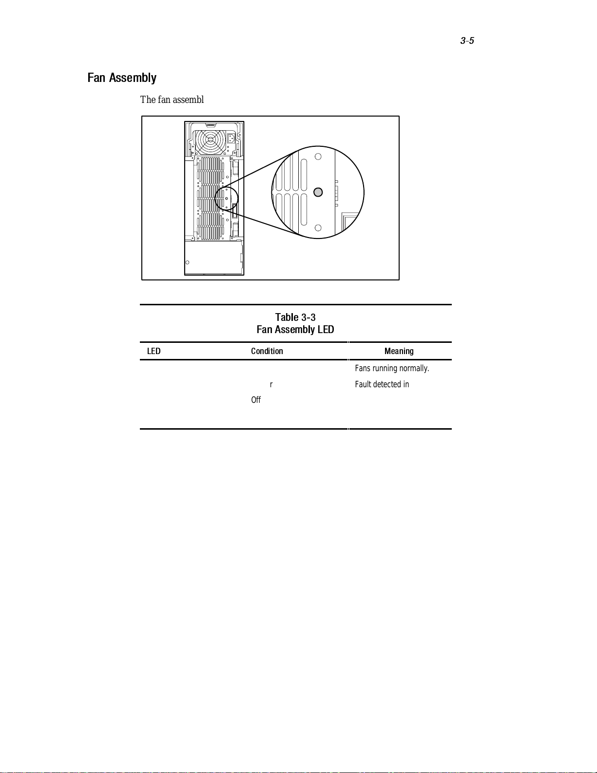
Fan Assembly
The fan assembly LED applies only to that module.
Figure 3-3. Fan Assembly LED
Table 3-3
Fan Assembly LED
Operation
3-5
LED Condition Meaning
Status Green
Amber
Off
Fans running normally.
Fault detected in one or
more fans.
No power connected to fan
array module.
Page 53

3-6
Compaq StorageWorks RAID Array 4000 User Guide
Hard Drives
The hard drive LEDs apply to the hard drive on which they are located.
Figure 3-4. Hard drive LEDs
Table 3-4
Hard Drive LEDs
LED Condition Meaning
Green Drive is configured and recognized by the controller.
Online Flashing Volume reconstruction or expansion is in progress.
DO NOT REMOVE THE DRIVE
Off Drive is inactive.
Green Drive is being accessed by the controller.
Drive Access Off Drive is not being accessed.
Amber Drive has failed and may be replaced.
Drive Failure Off Drive has not failed.
Page 54

This chapter contains troubleshooting procedures and suggestions that should
be followed to diagnose problems quickly and to minimize their impact on the
Compaq StorageWorks RAID Array 4000 operation.
Interpreting Component LEDs
If the fault LED on the front panel of the RA4000 is amber, or if Compaq
Insight Manager indicates a fault, determine the reason for this alert
immediately. Examine the component LEDs to see if any indicates a fault.
Chapter
Troubleshooting
Page 55

4-2
Compaq StorageWorks RAID Array 4000 User Guide
Hard Drive LEDs
CAUTION:
data.
Failure to observe the instructions in this section can result in loss of
Look for an amber Drive Failure LED on any hot-pluggable drive tray.
Figure 4-1. Drive Failure LED
If any Drive Failure LED is amber, replace that drive as soon as possible.
See “Replacing Components” later in this chapter for important information on
when it is safe to replace drives.
Page 56

Fibre Host Adapter LEDs
The Fibre Host Adapter has two status LEDs. The Transmit LED 1 indicates
that the Fibre Host Adapter is transmitting data over the Fibre Channel
Arbitrated Loop (FC-AL). The Receive LED 2 indicates that the Fibre Host
Adapter is receiving data.
1
2
Figure 4-2. Fibre Host Adapter/P LEDs
Troubleshooting
4-3
Figure 4-3. Fibre Host Adapter/E LEDs
2
1
Page 57

4-4
Compaq StorageWorks RAID Array 4000 User Guide
RA4000 Controller LEDs
During normal runtime, the RA4000 Controller has 18 LEDs that indicate
activity or malfunction of the controller. They are the Transmit LED 1, the
Receive LED 2, and sixteen status LEDs labeled 0-15. Table 4-1 describes the
purpose and function of each LED.
Figure 4-4. RA4000 Controller LEDs
1
1514 13 12 1110 9 8
76 54 32 10
2
Table 4-1
RA4000 Controller LED Descriptions
LED Function Description
0-2 Busy status ON = All LEDs on indicate this array controller is
idle
OFF = All LEDs off indicate this array controller is
operating at full capacity
3-7 Fibre Channel ID Indicates the 5-bit Arbitrated Loop Physical Address
(ALPA) assigned to this array controller
8 Heartbeat Blinks at 1Hz rate, indicating interrupts are enabled
and the array controller is functioning.
continued
Page 58

Troubleshooting
Table 4-1
RA4000 Controller LED Descriptions
LED Function Description
9 Active/Standby ON=Controller is active
10 WCXC active ON = Cache transfers are active
11 Logical I/O active ON = Currently processing logical requests from the
12 SCSI Bus 0 active ON = Indicates requests are outstanding on the first
13 SCSI Bus 1 active ON = Indicates requests are outstanding on the
14 Cache Activity/Error ON = Cache failure
15 Drive failure ON = A configured hard drive has filed in the array
continued
OFF=Controller is in standby
Host Adapter
SCSI bus
second SCSI bus
OFF = No cache activity
Blinking = Cache transfer pending
4-5
Transmit
LED
Receive
LED
Transmit mode ON = Indicates the array controller is transmitting
data over the FC-AL
Receive mode ON = Indicates the array controller is receiving data
over the FC-AL
Page 59

4-6
Compaq StorageWorks RAID Array 4000 User Guide
Fibre Channel Storage Hub LEDs
Storage Hub 7
The Fibre Channel Storage Hub 7 has two rows of LEDs. The top green LED
is lit when a GBIC is installed correctly in the receptacle.
Figure 4-5. GBIC-Installed LED on the Storage Hub 7
The bottom row of amber LEDs indicates when a specific port of the storage
hub is in bypass mode. When a GBIC is installed correctly and the port is not
in the bypass mode (normal), the LED is not lit.
Figure 4-6. Bypass mode LED on the Storage Hub 7
Page 60

Troubleshooting
Storage Hub 12
When power is applied, all LEDs will turn on during the self test, which lasts
15 to 60 seconds. After the power self test, the Power LED 1 stays lit and the
Fault LED 2 turns off.
2
1
Figure 4-7. Power and Fault LEDs on the Storage Hub 12
4-7
The GBIC-Installed LEDs are the upper green LEDs associated with each
GBIC receptacle. When a GBIC module is installed correctly, the
corresponding green LED turns on.
Figure 4-8. GBIC-Installed LED on the Storage Hub 12
Page 61
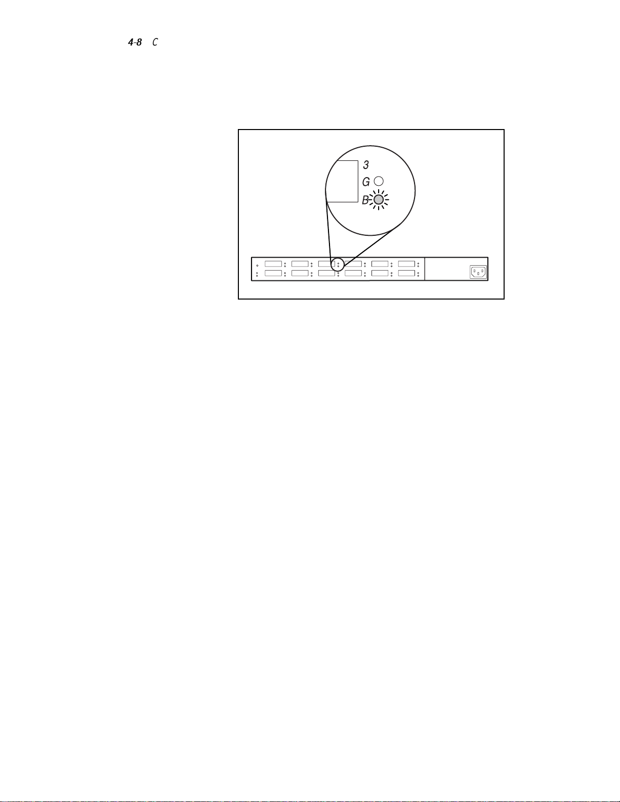
4-8
Compaq StorageWorks RAID Array 4000 User Guide
The lower amber LED is the Bypass Port LED, which indicates that the
associated port is in bypass mode. Ports that do not detect valid FC-AL links
are placed in bypass mode by the hub. The amber LED is turned on for each
port in the bypass mode.
Figure 4-9. Bypass mode LED on the Storage Hub 12
Page 62

Fan Assembly
Troubleshooting
4-9
CAUTION:
component damage.
Failure to follow the instructions in this section can result in
If the fan assembly LED is amber, the fan assembly must be replaced as soon
as possible.
Figure 4-10. Fan Assembly LED
See “Replacing Components” later in this chapter for important information on
how to replace this module.
CAUTION:
without a working Fan Assembly in place. Operation longer than this with no
forced air cooling, especially in arrays with a full complement of drives, may
permanently damage the drives or electronics in the RA4000 and result in data
loss.
When hot-plugging the Fan Assembly, be sure to have everything ready before
you begin the procedure, which should normally take no more than one minute.
Do not allow the RA4000 to operate for more than five minutes
Page 63

4-10
Compaq StorageWorks RAID Array 4000 User Guide
Power Supply
CAUTION:
data.
Failure to follow the instructions in this section can result in loss of
If the power 1 and status 2 LEDs are both OFF on one supply of a redundant
power supply system, check the AC power source to the supply. Redundant
operation is not assured until power is returned to the device.
Verify that the status LED 2 on the standard or redundant power supply
(if present) is amber.
1
2
Figure 4-11. Power supply LED
If this LED is amber, flashing amber, or alternating green/amber, replace the
power supply as soon as possible. See “Replacing Components” later in this
chapter for important information on how to replace the power supply.
Page 64

Replacing Components
Troubleshooting
4-11
CAUTION:
components in the RA4000. If the procedure is done improperly, it is possible to
lose data or damage equipment.
IMPORTANT:
(www.compaq.com) to make sure you have the latest firmware update.
It is important to follow these instructions when replacing
To take advantage of all features, check the Compaq website
Replacing the RA4000 Controller without RA4000
Redundant Controller
When an RA4000 Controller fails in an online active:
1. Perform a normal system shutdown of the servers that are using the
RA4000.
2. Power down the RA4000.
3. Unplug all power cords for the RA4000.
4. Remove the Fibre Channel cable 1 attached to the GBIC in the failed
RA4000 Controller.
5. Squeeze the tabs on either side of the GBIC 2, then remove the GBIC
by pulling it straight out of the RA4000 Controller 3.
2
3
1
Figure 4-12. Removing the Fibre Channel cable and GBIC
6. Squeeze the latches 1 and pivot open the two ejector levers 2 securing
the RA4000 Controller.
2
Page 65

4-12
Compaq StorageWorks RAID Array 4000 User Guide
7. Remove the RA4000 Controller by pulling it straight out of the
chassis 3.
1
2
Figure 4-13. Removing the RA4000 Controller
8. Install the replacement RA4000 Controller by inserting it into the tracks
in the rear panel opening.
9. Push the controller in as far as it will go 1 and close both latches
against the rear panel 2. The levers on each latch should catch behind
the metal lip, drawing the board into position and securing it into place.
1
3
2
1
2
Figure 4-14. Installing the RA4000 Controller
10. Replace the GBIC and connect the Fibre Channel cable.
11. Reconnect the power cords.
12. Power up the RA4000.
Page 66

13. Power up the servers attached to the RA4000.
The fault LED on the front panel of the RA4000 should now be green,
indicating a fully functioning system.
Replacing the RA4000 Controller with Redundant
Controller
1. Remove the Fibre Channel cable 1 attached to the GBIC in the failed
RA4000 Controller.
2. Squeeze the tabs on either side of the GBIC 2, then remove the GBIC
by pulling it straight out of the RA4000 Controller 3.
2
Troubleshooting
4-13
3
1
Figure 4-15. Removing the Fibre Channel cable and GBIC
3. Squeeze the latches 1 and pivot open the two ejector levers 2 securing
the RA4000 Controller.
2
Page 67

4-14
Compaq StorageWorks RAID Array 4000 User Guide
4. Remove the RA4000 Controller by pulling it straight out of the
chassis 3.
1
2
Figure 4-16. Removing the RA4000 Controller
5. Install the replacement RA4000 Controller by inserting it into the tracks
in the rear panel opening.
6. Push the controller in as far as it will go 1 and close both latches
against the rear panel 2. The levers on each latch should catch behind
the metal lip, drawing the board into position and securing it into place.
1
3
2
1
2
Figure 4-17. Installing the RA4000 Controller
7. Replace the GBIC and connect the Fibre Channel cable.
Page 68

Replacing the RA4000 Controller Cache
Troubleshooting
4-15
IMPORTANT:
require that you power down the system. If the cache is upgraded, or a different RA4000
Controller is to be reinstalled in the system, you must power down the system.
Replacing the RA4000 Controller cache with the same size cache does not
1. If you will be upgrading the cache or reinstalling a different RA4000
Controller, power down the servers attached to the RA4000, then power
down the RA4000.
2. Remove the Fibre Channel cable and GBIC from the existing RA4000
Controller.
3. Squeeze the front latches 1 and open the two ejector levers 2 securing
the RA4000 Controller.
4. Remove the RA4000 Controller by pulling it straight out of the
chassis 3.
1
1
2
3
Figure 4-18. Removing the RA4000 controller
Page 69

4-16
Compaq StorageWorks RAID Array 4000 User Guide
5. Twist the latch that is holding the daughterboard to the RA4000
Controller 90 degrees to allow the standoff to pull through the controller
board 1.
6. Carefully pull the daughterboard away from the controller board 2,
unplugging the signal connectors.
1
Figure 4-19. Removing the daughterboard
7. Align the connectors of the new daughterboard with the controller
board; plug the daughterboard onto the RA4000 Controller 1. Be sure
the connectors are fully mated by squeezing the boards together at the
connector side.
2
8. Align the plastic standoff on the daughterboard with the slot in the
controller board. Push it through and rotate the latch 90 degrees to lock
the board in place 2.
Page 70

Troubleshooting
1
2
Figure 4-20. Installing the daughterboard
9. With the daughterboard installed, push the RA4000 Controller in as far
as it will go 1.
10. Close both latches against the rear panel 2. The levers on each latch
should catch behind the metal lip, drawing the board into place and
securing it.
4-17
2
1
2
Figure 4-21. Replacing the RA4000 Controller
11. Replace the GBIC and reconnect the Fibre Channel cable.
12. If the system was powered down, power on the RA4000, and then
power on the attached servers.
Page 71

4-18
Compaq StorageWorks RAID Array 4000 User Guide
Replacing GBICs
If a GBIC fails, follow this procedure to replace the failed GBIC. It is not
necessary to power down the system.
1. Remove the Fibre Channel cable from the back of the failed GBIC.
Replace the protective covers on the cable 1.
2. Insert the dust plug covers into the GBIC module.
3. Squeeze the tabs on either side of the module 2 or, if equipped with a
locking mechanism, flip the bail to the unlocked position.
4. Pull the GBIC out of the device 3.
2
3
1
Figure 4-22. Removing the failed GBIC
2
5. To insert a new GBIC, reverse steps 1 through 4.
CAUTION:
excessive force when inserting the GBIC module.
To reduce the risk of damage to the equipment, do not use
Page 72

Removing Fibre Channel Cables
If a Fibre Channel cable fails, follow this procedure to replace the failed cable.
It is not necessary to power down the system.
1. Remove the failed Fibre Channel cable from the GBICs at both ends. If
a replacement cable cannot be connected to the GBICs immediately,
insert dust plug covers into the GBICs to protect them from
contamination.
2. Remove the protectors from the replacement Fibre Channel cable.
3. Insert the cable connectors into the GBIC modules.
Replacing the Power Supply
The power supply in the RA4000 is hot-pluggable if a redundant power supply
is installed. The power supply can be easily replaced by simply unplugging the
failed power supply, removing it, and plugging in a replacement. The second
power supply takes over for the first in this type of redundant configuration.
Single and redundant systems are described in the following two sections.
Follow the procedure that applies to your system.
Troubleshooting
4-19
WARNING:
the following precautions when connecting and disconnecting power to the
power supplies:
■ Install the power supply before connecting the power cord to the power
■ Unplug the power cord before removing the power supply from the
■ To completely remove power from a system, unplug all power cords from
IMPORTANT:
(www.compaq.com) to make sure you have the latest firmware update.
To reduce the risk of injury or damage to the equipment, observe
supply.
equipment.
the power supplies.
To take advantage of all features, check the Compaq website
Page 73

4-20
Compaq StorageWorks RAID Array 4000 User Guide
Single Power Supply Systems
1. Unplug the power cord for the failed power supply.
2. Press the latch on the power supply handle 1 and pivot the handle
open 2 to release the power supply. Pull the power supply away from
the chassis 3.
1
2
3
Figure 4-23. Removing the power supply
Page 74

Troubleshooting
3. With the handle fully open, insert the replacement power supply into the
opening and slide it in along the rails as far as it will go 1.
4. Pivot the handle closed until it snaps into place 2. This secures the
power supply in the chassis.
2
1
TROJ022.EPS
Figure 4-24. Installing the power supply
5. Plug in the power supply power cord.
4-21
The status LED on the power supply and the fault LED on the front panel of
the RA4000 should now be green, indicating that the new supply and the
storage system are fully operational.
Redundant Power Supply Option
In an RA4000 with the Redundant Power Supply option installed, two
identical power supplies power the RA4000. If either supply is faulty (amber
LED on the supply is lit), it can be replaced with the RA4000 power on,
without affecting normal system operation.
1. Unplug the power cord from the failed supply.
CAUTION:
the other power supply.
2. Press the catch on the power supply handle and pivot the handle open to
release the power supply. Pull the supply from the chassis.
See Figure 4-23.
If the system is running, be careful not to disturb the power cord for
Page 75

4-22
Compaq StorageWorks RAID Array 4000 User Guide
CAUTION:
power supply location open. Internal cooling air flow will be disrupted without a
power supply or blank cover installed in both locations. This could cause
overheating of internal components and possible data loss. In Redundant Power
Supply systems, retain the blank power supply cover for reuse in case it is
necessary to remove one of the supplies.
Do not operate the RA4000 for extended periods of time with either
3. With the handle fully open, insert the replacement power supply into the
opening and slide it in along the rails as far as it will go. It may be
necessary to wiggle the power supply from side to side, slightly, if any
resistance is felt along the rails.
4. Pivot the handle closed until it snaps into place. This secures the power
supply in the chassis. See Figure 4-24.
5. Plug the power cord into the new power supply.
The status LEDs on both power supplies and the fault LEDs on the front panel
of the RA4000 should now be green, indicating that power supply redundancy
has been restored.
Replacing the Fan Assembly
If the LED on the Fan Assembly is amber, a problem has been detected in at
least one of the three fans in the array. The entire module is hot-pluggable and
can be replaced without affecting normal system operation.
CAUTION:
without a working fan array module in place. Operation longer than this with no
forced air cooling, especially in systems with a full complement of drives, may
permanently damage the drives or electronics in the RA4000 and result in data
loss.
If the temperature gets too high, the RA4000 will automatically shut down the
power supply and redundant power supply, if installed.
When hot-plugging the fan assembly, be sure to have everything ready before
you begin the procedure, which should normally take no more than one minute.
Do not allow the RA4000 to operate for more than five minutes
Page 76

Troubleshooting
1. Loosen the two thumbscrews 1 securing the Fan Assembly to the
chassis.
2. Remove the Fan Assembly by pulling it straight out of the chassis 2.
1
2
Figure 4-25. Removing the Fan Assembly
3. Install the replacement Fan Assembly by sliding it into the opening
along the tracks as far as it will go 1, making sure that the connectors
mate.
4-23
4. Secure the Fan Assembly in place by tightening the two
thumbscrews 2.
2
1
Figure 4-26. Installing the Fan Assembly Module
Page 77

4-24
Compaq StorageWorks RAID Array 4000 User Guide
The three fans should start turning immediately. The status LED on the Fan
Assembly and the fault LED on the front panel will turn green after a few
seconds, indicating a fully functioning Fan Assembly.
Replacing Hard Drives
CAUTION:
follow the guidelines in this section. Failure to do so could result in data loss
and could void your warranty.
If you must replace a hot-pluggable drive, it is important that you
RAID 0 is not a fault-tolerant configuration. Never remove a drive from a
RAID 0 array unless it has failed. Drive failure is indicated by an amber Drive
Failure LED (see Figure 4-25). If you are using a RAID 0 configuration,
removal of an operating drive is not allowed and will result in loss of data. To
remove a working drive without losing data, the entire array must be backed
up, the drive must be replaced, and the entire array must be restored. Backing
up a single drive and replacing it will not restore the array.
There are some instances in which you may replace a drive in
RAID 1, 4, or 5 configurations. Figure 4-25 illustrates the conditions when
you may or may not remove a drive in a fault-tolerant system.
Page 78

Troubleshooting
4-25
troj016.EPS
Drive Indicators
OK to remove drive if not part
of fault-tolerant configuration
OK to remove failed drive
DO NOT remove drive
DO NOT remove drive
DO NOT remove drive
DO NOT remove drive
OFF ON Online Drive Access Drive Failure
Figure 4-27. Hot-pluggable drive replacement conditions
Page 79

4-26
Compaq StorageWorks RAID Array 4000 User Guide
To replace a drive:
Be sure that the Online and Drive Access LEDs are both OFF. See
Figure 4-10.
1. Squeeze the latches on the hard drive 1.
2. Pivot the ejector levers to the full open position 2.
1
Figure 4-28. Opening the drive tray latches
1
2
2
1
1
3. Pull the drive out of the storage system drive cage.
4. Open the latches fully on the replacement drive and insert the drive into
the same bay as the drive just removed, sliding it in as far as it will go.
Make sure the ejector levers are in the full open position to ensure a
correct latch.
Figure 4-29. Inserting the drive
Page 80

Troubleshooting
5. Close both latches against the front of the drive until they snap into
place 1. Levers on each latch should catch behind the metal lip at the
front of the bay 2, drawing the drive into position and securing it in
place.
1
1
2
Figure 4-30. Latching the drive into place
The drive tray LEDs light one at a time and then turn off together to indicate
that the system has recognized the new drive. In fault-tolerant configurations,
allow the replacement drive to be reconstructed automatically with data from
the other drives. While reconstruction is in progress, the Online LED flashes.
4-27
Page 81

Installing the Redundant Power Supply
The Redundant Power Supply option provides a second power supply to
supplement the standard supply so that one is always online.
Preparing the RA4000
Because this is a hot-pluggable option, it is not necessary to power down the
RA4000. However, be sure to observe these precautions.
Chapter
Option
WARNING:
the following guidelines when connecting and disconnecting power to the power
supplies:
■ Install the power supply before connecting the power cord to the power
■ Unplug the power cord before removing the power supply from the
CAUTION:
errors, damage to hard drives, and possible loss of data.
To reduce the risk of injury or damage to the equipment, observe
supply.
equipment.
Do not move a working storage system. This could cause hard drive
Page 82

5-2
Compaq StorageWorks RAID Array 4000 User Guide
Installation
Perform the following steps to install the Redundant Power Supply option in
the Compaq RA4000.
CAUTION:
cables on the back of a working RA4000. Accidentally disconnecting a cable
could cause loss of data.
CAUTION:
power supply location open. Internal cooling air flow will be disrupted without a
power supply or blanking panel installed in both locations. This could cause
overheating of internal components and possible data loss. In Redundant Power
Supply systems, retain the blank power supply cover in case it is necessary to
remove one of the supplies again in the future.
Be careful when working around the power and Fibre Channel
Do not operate the RA4000 for extended periods of time with either
1. Loosen the thumbscrew securing the blanking panel over the lower
power supply opening and remove the panel.
TROJ044.EPS
Figure 5-1. Removing the power supply blanking panel
2. Press the latch and pivot the handle on the Redundant Power Supply to
the fully open position.
Page 83

Installing the Redundant Power Supply Option
3. Align the power supply with the rail in its opening and push the supply
in as far as it will go 1.
4. Pivot the handle closed until it latches into place 2. This secures the
supply in the chassis.
2
1
Figure 5-2. Installing the redundant power supply
5-3
WARNING:
■ Do not disable the power cord grounding plug. The grounding plug is an
■ Plug the power cord into a grounded (earthed) electrical outlet that is
■ Disconnect power from the storage system by unplugging all power cords
To reduce the risk of electric shock or damage to the equipment:
important safety feature.
easily accessible at all times.
from either the electrical outlet or storage system.
5. Plug the new AC power cord into the Redundant Power Supply, then
into a grounded AC outlet.
The Power LED on the Redundant Power Supply will be green, indicating that
there is AC power available to the new supply. The Status LED on each
supply will also be green, indicating that no fault is detected. When the LEDs
on both power supplies are green, the RA4000 is protected against power
supply failure.
This completes the installation of the Redundant Power Supply option.
Page 84

Chapter
Running the Array Configuration Utility
This chapter provides instructions for using the Compaq Array Configuration
Utility (ACU) and describes methods for configuring your controller quickly
and easily. The Array Configuration Utility is located on the SmartStart and
Support Software CD.
The utility uses a graphic interface to help you configure the RA4000. You can
use the interface to configure the RA4000 initially, to add additional disk
drives to an existing configuration, or to reconfigure an array controller.
The Array Configuration Utility is supported online for the following
operating systems:
■ Microsoft Windows NT
■ Novell NetWare
ACU is an offline utility for all other supported operating systems.
This chapter includes the following sections:
■ Before You Begin
■ Starting the Compaq Array Configuration Utility
■ Configuration Wizards
■ Online Help
■ Configuration Procedures
■ Array Configuration Utility Screens
Page 85

6-2
Compaq StorageWorks RAID Array 4000 User Guide
■
Error and Warning Messages
■
NetWare Online Array Configuration Utility
The Array Configuration Utility:
■
Uses easy-to-understand graphics to illustrate controller configuration
■
Describes various configuration errors
■
Uses wizards that guide you through the configuration process
■
Suggests optimal configuration and fault tolerance for unconfigured
controllers
Before You Begin
During a first-time installation and configuration of the RA4000, complete the
following:
1. Update the system ROM with System ROMPaq.
2. Run Options ROMPaq to update the controller firmware, option ROM,
and drive firmware.
3. Run the System Configuration Utility to verify the controller order
settings.
4. Determine which fault-tolerance method and array configuration to use.
Starting the Array Configuration Utility
You can access and start version 2.30 or later of the Array Configuration
Utility online, or by using the SmartStart and Support Software CD.
NOTE:
In multi-initiator environments, only one instance of the ACU can be used to
configure drive arrays on a Fibre Channel Arbitrated Loop at one time.
Page 86

Accessing Online
If the server you are configuring is running Windows NT, you can install and
run the Array Configuration Utility online.
When the Compaq Software Support Diskette for Microsoft Windows NT
(NT SSD) is installed, the diskette prompts you to insert the Array
Configuration Utility diskette to install the utility. A program icon is created
automatically. Select the icon to run the Array Configuration Utility.
NOTE:
See the section “NetWare Online Configuration Utility” in this chapter for
information on accessing and using this online utility. The NetWare utility uses a menudriven, non-graphic interface. To use the graphic interface, select one of the methods
explained in the following sections to use the Compaq Array Configuration Utility offline.
SmartStart and Support Software CD
To run the Array Configuration Utility from the SmartStart and Support
Software CD:
1. Insert the SmartStart and Support Software CD in the CD drive and
power up the server. A menu is displayed.
Running the Array Configuration Utility
6-3
2. Select the Array Configuration Utility.
3. After completing the configuration, remove the CD and restart the
server.
Page 87
6-4
Compaq StorageWorks RAID Array 4000 User Guide
Configuration Wizards
When the Array Configuration Utility is started, the software checks the
configuration of the RA4000 and its drive arrays. If the arrays are
unconfigured or if the configuration is less than optimal, the configuration
wizard guides you through the configuration process. The configuration
wizard recognizes the following conditions:
■
Unconfigured controller—When the Array Configuration Utility
detects an unconfigured controller, the configuration wizard leads you
through the controller configuration process.
■
Unused physical drives—When the Array Configuration Utility detects
unused physical drives, the configuration wizard provides an easy way
to add them to an array. The “capacity expansion” capability of the
RA4000 allows the Array Configuration Utility to add new physical
drives to an existing array without destroying data on the existing
logical drives.
■ Unused space on an array—If the Array Configuration Utility detects
unused capacity in an array, the configuration wizard leads you through
the process of configuring the space into one or more logical drives.
Getting Help
Press F1 or click the Help button to activate context-sensitive, online help for
each screen. A status bar at the bottom of the screen also displays help
messages describing the current selection.
Page 88

Configuration Procedures
If you are configuring a new array, the configuration wizard leads you through
the process. You can, however, bypass the wizard and manually:
■
Create a new array
■
Expand the capacity of an array
■
Extend the capacity of a logical drive
■
Perform online stripe size migration
■
Perform online RAID level migration
Use the procedures in the following sections to configure your array manually.
Create a New Array
Creating a New Array Procedure
There are three general steps for creating a new array:
1. Choose a controller for the array.
Running the Array Configuration Utility
6-5
2. Group physical drives of the same size into an array.
3. Create logical drives. (Divide the array into one or more logical drives.)
Creating a New Array Example
For this example, use the following assumptions:
■ Four 4.3-GB drives and two 9.1-GB drives are connected to the
RA4000.
■ There will be two arrays. Array A consists of three 4.3-GB drives, with
the fourth 4.3-GB drive used as a spare. Array B has two 9.1-GB drives.
■ The fault-tolerance method for all logical drives on Array A is RAID 5,
Distributed Data Guarding. The fault-tolerance method for all logical
drives on Array B is RAID 1, Drive Mirroring.
Step 1: Choosing a Controller for the Array
1. In the Array Configuration Utility Main Configuration Screen, select the
Controller Selection box. You can also select Controller/Select from the
menu bar.
Page 89

6-6
Compaq StorageWorks RAID Array 4000 User Guide
2. Select one of the listed controllers.
Figure 6-1. Controller Selection list
3. Click the Controller Settings button shown in the following figure.
Figure 6-2. Controller buttons
Page 90

Running the Array Configuration Utility
The controller setting screen displays, as shown in Figure 6-3.
4. Select the correct operating system on the Controller Settings screen.
6-7
Figure 6-3. Controller Settings screen
Page 91
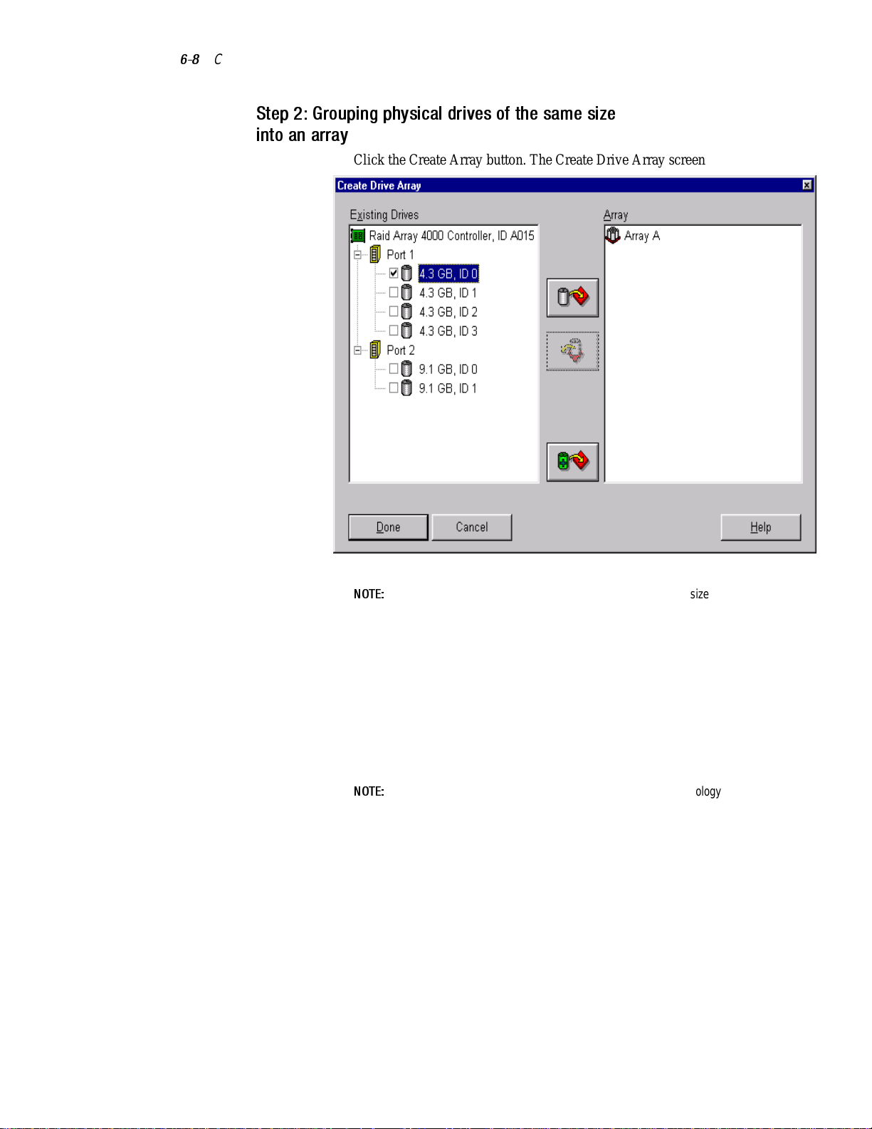
6-8
Compaq StorageWorks RAID Array 4000 User Guide
Step 2: Grouping physical drives of the same size
into an array
1. Click the Create Array button. The Create Drive Array screen appears.
Figure 6-4. Create Drive Array screen
NOTE:
Always group physical drives of the same size. If you mix drive sizes, the capacity
of the larger drives is wasted.
Select the three drives you want to make up the array from the drives on
the left. For this example, the following drives were selected:
q Port 1:SCSI ID 0
q Port 1:SCSI ID 1
q Port 1:SCSI ID 2
2. Click the Assign Drive(s) to Array button.
NOTE:
Given the reliability of a particular generation of hard drive technology, the
probability of an array experiencing a drive failure increases with the number of drives in
an array. Compaq recommends that you limit the number of drives in an array to 14.
Page 92

Running the Array Configuration Utility
3. Select the drive at Port 1:SCSI ID 3 and click the Assign Spare to Array
button update as advised. The Create Array screen should look similar
to the following figure.
6-9
Figure 6-5. Example Array A
NOTE:
The same spare drive can be assigned to multiple arrays. However, spare drives
should have the same or greater capacity as the drives in the array.
Page 93

6-10
Compaq StorageWorks RAID Array 4000 User Guide
4. Click the Done button to return to the Main Configuration screen. The
Logical Configuration View area should look similar to the following
figure.
Figure 6-6. Example Array - Logical Configuration View with one Array
5. Select the controller, then click the Create Array button to create
Array B.
6. Assign both 9.1-GB drives to the array, then click the Done button.
NOTE:
In this example, each array was created using drives from the same SCSI Port.
You can achieve better performance by selecting drives from both ports for an array,
assuming you installed the correct drives in both ports before you ran the Array
Configuration Utility.
Page 94

Step 3: Creating Logical Drives
When creating a logical drive, you can select a fault-tolerance (RAID level)
option and provide information regarding the drive size, array accelerator, and
stripe size.
1. Select Array A or the Unused Space icon under Array A in the Logical
Configuration View.
2. Click the Create Logical Drive button. A screen similar to the following
figure is displayed.
Running the Array Configuration Utility
6-11
Figure 6-7. Create Logical Drive screen
3. In the upper-left area of this screen, click the Distributed Data Guarding
(RAID 5) option button.
4. Click the Array Accelerator Enable button.
5. Stripe Size can be left at the default for the selected RAID level, or set
to another value. See the section titled “Creating Logical Drive Screen”
later in this chapter for a detailed description.
Page 95

6-12
Compaq StorageWorks RAID Array 4000 User Guide
6. The Logical Drive Size area includes a graphical representation of the
storage capacity available. To create a single logical drive across this
array, accept the default values. See the section titled “Creating Logical
Drive Screen” for a detailed description.
7. Click the Done button.
8. Click Array B or the Unused Space icon under Array B in the Logical
Configuration View.
9. Repeat steps 3 through 7 to create a single logical drive on Array B, this
time selecting RAID 1 fault tolerance.
10. The Configuration View screen should look like Figure 6-8.
Figure 6-8. Example array - Configuration View screen with two Arrays
Page 96

Capacity Expansion
Capacity expansion involves adding storage capacity to an array that has
already been configured. If an existing array is nearly full of data, you can
expand the capacity without disturbing the existing data. The RA4000 capacity
expansion feature allows new physical drives to be added to the array.
When the Array Configuration Utility runs, the program checks the drive
hardware and configuration. If the Array Configuration Utility discovers a
physical drive that is not being used, the configuration wizard leads you
through the steps for adding the drive.
Expanding Array Capacity Procedure
To bypass the configuration wizard:
1. Install the new physical drives.
NOTE:
Always group physical drives of the same size. If you mix drive sizes, the capacity
of the larger drives is wasted.
2. Assign the new physical drives to an existing array. Existing logical
drives will automatically expand across the physical drives, including
the newly added ones.
Running the Array Configuration Utility
6-13
3. Create a new logical drive to use the extra space on the expanded array.
See the following example.
Page 97

6-14
Compaq StorageWorks RAID Array 4000 User Guide
Expanding Array Capacity Example
For this example, assume a configuration similar to the previous one, except
that the fourth 4.3-GB drive was added later (where Array A does not have a
spare). Expand Array A to include the fourth drive. This scenario is
represented in the following figure with a single 4.3-GB drive unassigned.
Figure 6-9. Array expansion example - Configuration View screen
To expand the capacity of Array A and create Logical Drive 2:
1. Select Array A.
2. Click the Expand button.
3. Select the unassigned 4.3-GB drive.
4. Click Assign Drives to Array.
Page 98

Running the Array Configuration Utility
5. Click the Next button at the bottom of the screen. A screen similar to the
following figure is displayed.
6-15
Figure 6-10. Expansion wizards - Logical Drive screen
6. Click the Create Logical Drive button.
7. Set the fault tolerance, array accelerator, stripe size, and size for Logical
Drive 2.
8. Click the Done button.
Page 99

6-16
Compaq StorageWorks RAID Array 4000 User Guide
9. At the main screen, select Controller, Save Configuration from the
menu bar. This saves the new settings for Logical Drive 2 and starts the
capacity expansion process.
NOTE:
completed on Logical Drive 1.
Capacity Extension
Logical drive extension allows you to increase the size of existing logical
drives without disturbing the data on those logical drives. If an existing logical
drive is full of data, you can extend the logical drive when there is free space
on the array. If there is no free space on the array, add drives to the array and
extend the logical drive.
IMPORTANT:
extend logical drives that are used with an operating system that supports extension.
Extending Logical Drives Operating Systems
The following operating systems support logical drive extension:
■ Microsoft Windows NT 4.0
CAUTION:
temporarily stored in the Array Accelerator memory. To prevent the loss of data
in the expanding logical drive, do not interchange RA4000 controllers or Array
Accelerator boards during a capacity expansion process.
Logical Drive 2 will not be accessible until the capacity expansion process has
In case of power loss, capacity expansion process information is
Logical drive extension is not supported by all operating systems. Only
■ NetWare 5.0
■ OS/2 WarpConnect
■ OS/2 WarpServer
■ OS/2 WarpServer (Advanced)
■ OS/2 WarpServer SMP
■ OS/2 Warp 4.0
■ SCO OpenServer 5
■ SCO UnixWare 7
■ SCO UnixWare 2
Page 100

Running the Array Configuration Utility
If your operating system is not listed, check your operating system
documentation or contact your operating system vendor before extending
logical drives.
Extending Logical Drives Procedure
To extend the capacity of a logical drive:
1. Click the logical drive that you want to extend.
2. Click the Drive menu.
3. Select Extend Logical Drive.
NOTE:
The Extend Logical Drive screen displays the current capacity and RAID overhead
of the selected logical drive (Figure 6-11).
6-17
Figure 6-11. Extend Logical Drive screen
4. Click the slider control to change (increase) the size of the logical drive.
NOTE:
You cannot reduce the size of the logical drive from this screen.
5. Click Done.
6. Save the logical drive by clicking the Controller menu and selecting the
Save Configuration option.
The logical drive will be restructured so that its data is preserved. Refer to the
status gauge at the lower right of the screen to monitor the progress.
 Loading...