

Hp COMPAQ PROSIGNIA 200, COMPAQ PROSIGNIA 740, COMPAQ PROLIANT 2000 Compaq Recovery Server Solutions for SAP R/3 on Various Database Platforms
Page 1
WWHITE HITE PPAPERAPER
switchover process, a second identically configured server becomes the active server and is
.
.
[December 1996, Version 1.0
Compaq Computer Corporation
CONTENTS
IntroductionIntroduction .................................... 44
Compaq RecoveryCompaq Recovery
Server SolutionsServer Solutions
OverviewOverview ............................................ 44
SAP R/3 andSAP R/3 and
Recovery ServerRecovery Server
SolutionsSolutions
ImplementationImplementation
ConsiderationsConsiderations ............................ 55
Standby RecoveryStandby Recovery
Server TechnologyServer Technology.................. 66
Normal Operation ............. 7
Switchover Events ............ 8
Switchover Time..............10
Faults ............................10
Servicing the Failed Server12
Restoring the Configuration
After Switchover..............12
Client Behavior ...............12
Disk Subsystem
Considerations ................13
Setting Up aSetting Up a
Standby RecoveryStandby Recovery
ServerServer.................................................. 1414
System Configuration.......14
Testing the Configuration .15
R/3 Software Specific
Settings .........................16
On-Line RecoveryOn-Line Recovery
Server TechnologyServer Technology................1717
SAP R/3SAP R/3
ImplementationImplementation
considerations forconsiderations for
On-line RecoveryOn-line Recovery
ServerServer.................................................. 2121
Normal Operation ............22
Switchover Events ...........23
Application Notification ....23
Switchover Time..............24
Planned Shutdown ...........25
Faults ............................26
Cable Fault.....................26
Servicing the Failed
Server............................26
Restoring the Configuration
After Switchover..............26
Client Behavior ...............27
Performance
Considerations ................27
ContinuedContinued
Doc Number 465A/1196
.
.
.
Compaq Recovery Server Solutions for SAPCompaq Recovery Server Solutions for SAP
.
.
.
.
.
.
.
R/3 on Various Database PlatformsR/3 on Various Database Platforms
.
.
.
.
.
.
.
.
.
.
EXECUTIVE SUMMARY
.
.
.
.
Compaq has developed a number of products to minimize downtime for business-critical
.
.
.
.
application servers like those running SAP R/3. Several features like redundant power
.
.
.
supply, backup processor, ECC memory, hot-pluggable disks, and disk array fault
.
.
.
tolerance make the likelihood of a server failure extremely low. Nevertheless, Compaq
.
.
.
keeps working on increasing the availability and dependability of its platforms and has
.
.
.
released two new products that further guarantee the reliability of Compaq platforms:
.
.
.
Standby Recovery Server and On-Line Recovery Server.
.
.
.
.
.
The Compaq Standby Recovery Server offers minimum downtime for customers with SAP
.
.
.
R/3 servers where on-site technical expertise is not available. With the Compaq automated
.
.
.
.
.
.
.
back on-line in a matter of minutes.
.
.
.
.
.
.
.
.
R/3-Database
.
.
.
Server
.
.
.
.
.
.
.
.
.
.
.
.
.
.
.
.
.
.
.
.
.
.
.
.
.
.
.
.
.
.
.
.
.
.
.
.
.
.
.
.
.
.
.
.
.
.
.
.
.
.
.
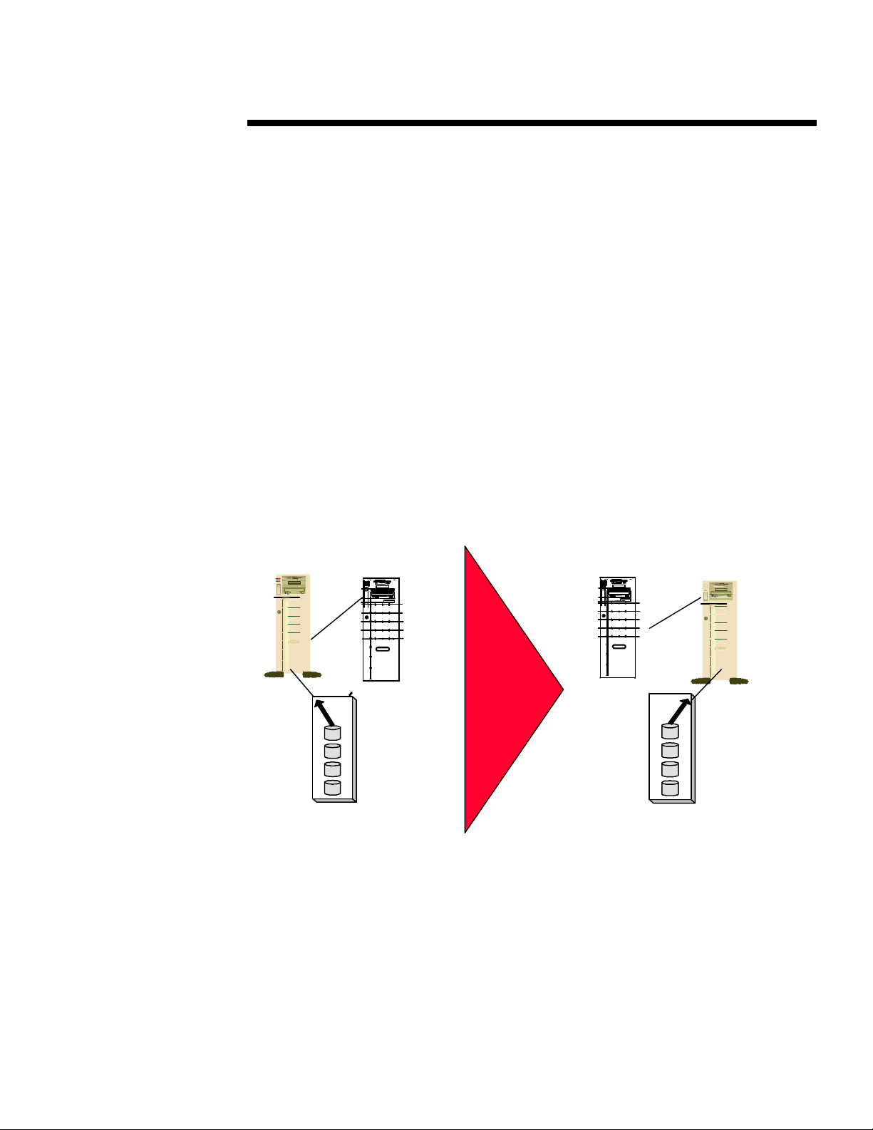
Figure 1. Standby Recovery Server
.
.
.
.
.
.
In the Standby Recovery Server configuration, two Compaq ProLiant servers are
.
.
.
attached to a Compaq ProLiant Storage System containing a copy of the Microsoft
.
.
.
.
Windows NT operating system, R/3 application software, database software, and the
.
.
.
database itself. If the R/3-Database server fails, the ProLiant Storage System
.
.
.
automatically switches to the recovery server. The recovery server then boots, and the
.
.
.
system is back on-line in minutes without administrator intervention.
.
.
.
.
.
.
.
.
.
.
.
.
.
11
ProLiant
Storage System
Data
Data
Data
Data
Recovery
Server
Off-line
Off-line
Off-line
Off-line
R/3-Database
Server
ProLiant
Storage System
R/3-Database
Server
Data
Data
Data
Data
Page 2
WWHITE HITE PPAPERAPER (cont.)
SW
Data
Data
Data
O.S.
O.S.
O.S.
O.S.
SW
Data
Data
Data
O.S.
O.S.
O.S.
O.S.
.
.
Setting Up an On-Setting Up an OnLine RecoveryLine Recovery
ServerServer.................................................. 2828
System Configuration.......29
On-Line Recovery Server
Software Installation........30
Testing the Configuration.33
R/3-DatabaseR/3-Database
Server SpecificServer Specific
SettingsSettings ............................................3535
GlossaryGlossary ..........................................4141
APPENDIX 1:APPENDIX 1:
Windows NTWindows NT
Resource Kit ToolsResource Kit Tools ..............4343
APPENDIX 2:APPENDIX 2:
CPQIPSETCPQIPSET......................................4545
APPENDIX 3: Post-APPENDIX 3: Post-
Switchover ScriptSwitchover Script ..................4646
APPENDIX 4: PostAPPENDIX 4: Post
Switchover INI-Switchover INI-
FilesFiles...................................................... 5151
APPENDIX 5:APPENDIX 5:
Sample AlternateSample Alternate
Profiles forProfiles for
Recovery ServerRecovery Server ......................5353
APPENDIX 6:APPENDIX 6:
Sample Profiles forSample Profiles for
Application ServerApplication Server ................5555
APPENDIX 7:APPENDIX 7:
Sample AlternateSample Alternate
Profiles forProfiles for
Application ServerApplication Server ................5656
APPENDIX 8:APPENDIX 8:
Sample UnswitchSample Unswitch
Batch FileBatch File ........................................5858
Doc Number 465A/1196
The Compaq On-Line Recovery Server offers a cost-effective means of increasing
.
.
.
.
capacity and availability of business-critical SAP R/3 applications for customers with
.
.
.
numerous servers operating in the Windows NT 3.5x environment. This Recovery Server
.
.
.
solution pairs two independently operating Compaq ProLiant servers as hot (on-line)
.
.
.
partners for each other while maintaining flexibility for multiple server configurations.
.
.
.
.
.
.
.
.
.
.
R/3-Database - Server
.
.
.
.
.
.
.
.
.
.
.
.
.
.
.
.
.
.
.
.
.
.
.
.
.
.
.
.
.
.
.
.
.
.
.
.
.
.
.
.
.
ProLiant
.
.
Storage
.
.
System
.
.
.
.
.
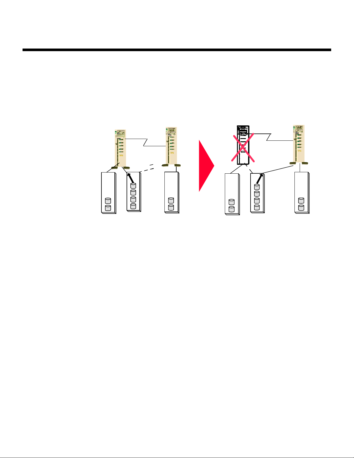
Figure 2. On-Line Recovery Server in an Asymmetrical Configuration
.
.
.
.
.
.
.
The On-Line Recovery Server allows users from one system to be supported by another
.
.
.
.
system automatically in the event of a failure. The On-Line Recovery Server allows
.
.
.
applications to be up and running with minimal interruption, and is designed to work
.
.
.
with the comprehensive alert features of Compaq Insight Manager. The On-Line
.
.
.
Recovery Server also allows servers to be serviced or replaced easily.
.
.
.
.
.
Details associated with operating environment, application software, and existing
.
.
.
hardware should be examined before making final decisions to deploy the Recovery
.
.
.
Server solutions. This white paper focuses on configuration and implementation aspects
.
.
.
that are specific to SAP R/3 platforms.
.
.
.
.
.
The solutions described in this white paper are available for Microsoft SQL Server 6.5 ,
.
.
.
Oracle 7.2, and Software AG ADABAS/D 6.1.1.
.
.
.
.
.
.
.
.
.
.
.
.
.
.
.
.
.
.
.
.
.
.
.
.
.
.
.
.
.
.
.
.
.
.
.
.
.
.
.
.
22
Switchable
Proliant
Storage
System
Server 2
ProLiant
Storage
System
R/3-Database Server
Server 1
Server 1
Fails
Fails
ProLiant
Storage
System
Switchable
Proliant
Storage
System
R/3-Database Server
ProLiant
Storage
System
Page 3

WWHITE HITE PPAPERAPER (cont.)
.
.
.
NOTICE
.
.
.
.
.
.
The information in this publication is subject to change without notice.
.
Doc Number 465A/1196
.
.
.
.
Compaq Computer Corporation shall not be liable for technical or editorial errors or
.
.
omissions contained herein, nor for incidental or consequential damages resulting from the
.
.
.
furnishing, performance, or use of this material.
.
.
.
.
.
This publication does not constitute an endorsement of the product or products that were tested.
.
.
.
The configuration or configurations tested or described may or may not be the only available
.
.
.
solution. This test is not a determination of product quality or correctness, nor does it ensure
.
.
.
compliance with any federal, state or local requirements. Compaq does not warrant products
.
.
.
other than its own strictly as stated in Compaq product warranties.
.
.
.
.
Product names mentioned herein may be trademarks and/or registered trademarks of their
.
.
.
respective companies.
.
.
.
.
Compaq, Contura, Deskpro, Fastart, Compaq Insight Manager, LTE, PageMarq, Systempro,
.
.
.
Systempro/LT, ProLiant, TwinTray, LicensePaq, QVision, SLT, ProLinea, SmartStart, NetFlex,
.
.
.
DirectPlus, QuickFind, RemotePaq, BackPaq, TechPaq, SpeedPaq, QuickBack, PaqFax,
.
.
.
registered United States Patent and Trademark Office.
.
.
.
.
.
Aero, Concerto, QuickChoice, ProSignia, Systempro/XL, Net1, SilentCool, LTE Elite, Presario,
.
.
.
SmartStation, MiniStation, Vocalyst, PageMate, SoftPaq, FirstPaq, SolutionPaq, EasyPoint, EZ
.
.
Help, MaxLight, MultiLock, QuickBlank, QuickLock, TriFlex Architecture and UltraView,
.
.
.
CompaqCare and the Innovate logo, are trademarks and/or service marks of Compaq Computer
.
.
.
Corporation.
.
.
.
.
.
Other product names mentioned herein may be trademarks and/or registered trademarks of their
.
.
.
respective companies.
.
.
.
.
©1996 Compaq Computer Corporation. Printed in the U.S.A.
.
.
.
.
.
Microsoft, Windows, Windows NT, Windows NT Advanced Server, SQL Server for Windows
.
.
NT are trademarks and/or registered trademarks of Microsoft Corporation.
.
.
.
.
.
ADABAS /D is trademark and/or registered trademark of Software AG.
.
.
.
.
.
.
.
.
.
.
.
.
.
Compaq Recovery Server Solutions for SAP R/3 on various platforms
.
.
.
.
.
.
.
First Edition (December 1996)
.
.
Document Number 465A/1196
.
.
.
.
.
.
.
.
.
.
.
.
.
.
.
.
.
.
.
.
.
.
.
.
.
.
.
.
.
.
.
.
.
.
.
.
.
.
.
33
Page 4

WWHITE HITE PPAPERAPER (cont.)
.
.
.
.
.
.
INTRODUCTION
.
.
.
.
.
Doc Number 465A/1196
The purpose of this White Paper is to help customers implement Compaq Recovery Server
.
.
.
solutions in an environment using SAP R/3 with its related database platform. This White Paper
.
.
.
addresses the process for:
.
.
.
.
• Setting-up the platforms for either Compaq Standby Recover Server or Compaq On-Line
.
.
.
.
.
.
.
.
.
.
.
.
.
.
.
.
.
.
.
.
.
.
.
.
.
.
.
.
.
.
.
.
.
.
.
.
.
.
.
.
.
.
.
.
.
.
.
.
.
.
.
.
.
.
.
.
.
.
.
.
.
.
.
.
.
.
.
.
.
.
.
.
.
.
.
.
.
.
.
.
.
.
.
.
.
.
.
.
.
.
.
.
.
.
.
.
.
.
.
.
.
.
.
.
.
.
.
.
.
.
.
.
.
.
.
.
.
.
.
.
.
.
.
.
.
.
.
.
.
.
.
.
.
.
.
.
Recovery Server
• Configuration specifications necessary for SAP R/3
• Using the database to be implemented in a recovery mode
This White Paper includes information extracted from other Compaq White Papers and technical
documentation. The level of detail in this White Paper should explain the technical concepts fully
and provide information on implementing the concepts in practical situations. You can find
additional details in the following Compaq White Papers:
Compaq Standby Recovery Server (document number 180B/0495)
Compaq On-Line Recovery Server (document number 043A/1095)
You can also find details in the Recovery Server Option User Guide (part number
213818-002), which comes with the Recovery Server Option Kit and is also available as an
independent product.
The majority of this White Paper discusses the On-Line Recovery Server implementation.
Because the Standby Recovery Server solution is application-independent, SAP R/3 requires no
special or specific configuration changes. The On-Line Recovery Server solution requires specific
configuration and implementation processes to automatically start up the database and the SAP
R/3 instance on the recovery server. This process of starting the database and R/3 is illustrated by
means of script files, which are platform-specific and must be adapted to the particular
configuration of each platform.
The modular, distributed architecture of SAP R/3 makes it suitable for either of the Compaq
Recovery Server solutions. Due to the sophistication of this architecture, and the critical nature of
a R/3 system, the recovery procedures must be fully compliant with the specifications for recovery
software provided by the SAP High Availability Guide. This document describes methods and
techniques that have been tested as specified in that guide.
COMPAQ RECOVERY SERVER SOLUTIONS OVERVIEW
In the Standby Recovery Server configuration, one server functions as the primary server and
another server functions as a hot standby recovery server that remains idle until a there is a
switchover. All disk storage is external to both servers. The disk storage switches from the
primary server to the recovery server when a fault is detected via the Compaq Recovery Server
Switch. The Recovery Server Switch is an electrically controlled SCSI switch that allows selected
storage devices to be switched dynamically from the failed server to the surviving server.
The On-Line Recovery Server configuration pairs an independently operating Compaq server as
an automatic, hot standby for the primary server. If the primary server fails, the ProLiant Storage
System(s) attached to the failed server will be automatically switched over to the surviving server
via the Compaq Recovery Server Switch.
Table 1 summarizes the differences between the two recovery server configurations.
44
Page 5

WWHITE HITE PPAPERAPER (cont.)
.
.
.
.
.
.
.
.
.
.
Doc Number 465A/1196
.
.
.
.
.
.
.
.
.
.
.
.
.
.
.
.
.
.
.
.
.
.
.
.
.
.
.
.
.
.
.
.
.
.
.
.
.
.
.
.
.
.
.
.
.
.
.
.
.
.
.
.
.
.
.
.
.
.
.
.
.
.
.
.
.
.
.
.
.
.
.
.
.
.
.
.
.
.
.
.
.
.
.
.
.
.
.
.
.
.
.
.
.
.
.
.
.
.
.
.
.
.
.
.
.
.
.
.
.
.
.
.
.
.
.
.
.
.
.
.
.
.
.
.
.
.
.
.
.
.
.
.
.
.
.
.
.
.
.
.
.
.
.
.
.
.
.
COMPARISON OF STANDBY AND ON-LINE CONFIGURATION
StandbyStandby On-LineOn-Line
Single network identity. Only the primary server is active
on the network.
Single active server. Two active servers.
Switchover restores operating system and applications. Switchover restores only switched disks. Operating
Benefits all applications. Benefits specific application(s).
No local disks. Local disk (to contain at least the operating system)
SAP R/3 AND RECOVERY SERVER SOLUTIONS
IMPLEMENTATION C ONSIDERATIONS
A typical R/3 platform consists of one database server and a variable number of application
servers, depending on the processing requirements imposed by the workload. SAP R/3 services
are distributed among these servers according to processing requirements imposed by the user
workload. Some of these services can have several instances running on different servers, but
others must run just once on a certain server in the configuration. These are single points of
failure of a R/3 system.
To minimize unplanned R/3 system downtime, all single points of failure in a system should be
secured. A single point of failure can be defined as a component that will lead to (severe) service
loss in case of failure.
Table 2 shows the services offered by the R/3 system. Single points of failure appear in italics and
are underlined.
ServiceService Number of InstancesNumber of Instances
DBMS 1 per R/3 System
Dispatcher 1 per App-Server
Dialog service 1 ... n per App-Server
Update service 0 ... n per App-Server
Enqueue service 1 per R/3 System
Batch service 0 ... n per App-Server
Message service 1 per R/3 System
Gateway service 1 per R/3 Instance
Spool service 1 per App-Server
55
TABLE 1
Two network identities. The primary on recovery server
are active servers on the network.
system is stored and runs of on local disks.
required along with switched disks.
TABLE 2
R3 SERVICES
Page 6

WWHITE HITE PPAPERAPER (cont.)
.
.
If only one single point of failure is protected, some R/3 services will still be left unprotected. If
.
.
.
one of the remaining single points of failure subsequently fails, the R/3 system will be
.
.
.
unavailable (until R/3 has been reconfigured and restarted). It is therefore recommended to
.
.
.
Doc Number 465A/1196
concentrate all single points of failure on a server that is protected by one of the Compaq
.
.
.
Recovery Server solutions.
.
.
.
.
The database server, also running the enqueue and message services, as well as sapcomm and
.
.
.
saprouter, is a primary candidate for a recovery server implementation because its availability is
.
.
.
crucial to the functioning of the whole R/3 system. If an R/3 application server fails, users are
.
.
.
still able to work because they can reconnect to a dialog instance running on a different
.
.
.
application server or on the database server. Furthermore in such a case, the reconnection could
.
.
.
be automatically provided by the R/3 load balancing mechanism.
.
.
.
.
.
.
.
STANDBY RECOVERY SERVER TECHNOLOGY
.
.
.
.
.
The Standby Recovery Server solution automatically switches all shared disk storage from a
.
.
failed R/3-Database server to a standby recovery server that is waiting to boot the Windows NT
.
.
.
operating system and re-establish access to database files that are stored on the shared drives.
.
.
.
When a switchover occurs, the recovery server electrically switches all of the disk storage from
.
.
.
the primary server to the disk controller contained in the recovery server. When the switchover
.
.
.
is complete, the recovery server begins a normal operating system boot sequence using the same
.
.
.
disks that were previously attached to the primary server.
.
.
.
.
.
The primary and recovery server systems are not required to be identical. However, there are
.
.
.
configurations guidelines that must be met in order for the Standby Recover Server
.
.
configuration to function properly. Although, Compaq recommends that the two servers be
.
.
.
identical.
.
.
.
.
.
Both the primary server and recovery server are connected by a SCSI cable to a Compaq
.
.
.
ProLiant Storage System, which holds a single copy of the Windows NT operating system, R/3
.
.
.
application software, database executables, and the database.
.
.
.
.
The Recovery Server Switch, an electrically controlled SCSI switch, must be installed in each
.
.
.
switchable Compaq ProLiant Storage System. This Recovery Server Switch actually
.
.
.
accomplishes the electrical switching of the disk storage that has a SCSI cable connection to the
.
.
.
primary and recovery servers. All disk storage in Standby Recovery Server configurations must
.
.
.
be contained in external ProLiant Storage Systems that have had the Recovery Server Switch
.
.
.
installed. No disks can be installed internal to the Compaq server. No disks can be attached to the
.
.
.
integrated SCSI controller of the Compaq server. The integrated SCSI controller can however be
.
.
.
used for CD-ROM drives and tape drives.
.
.
.
.
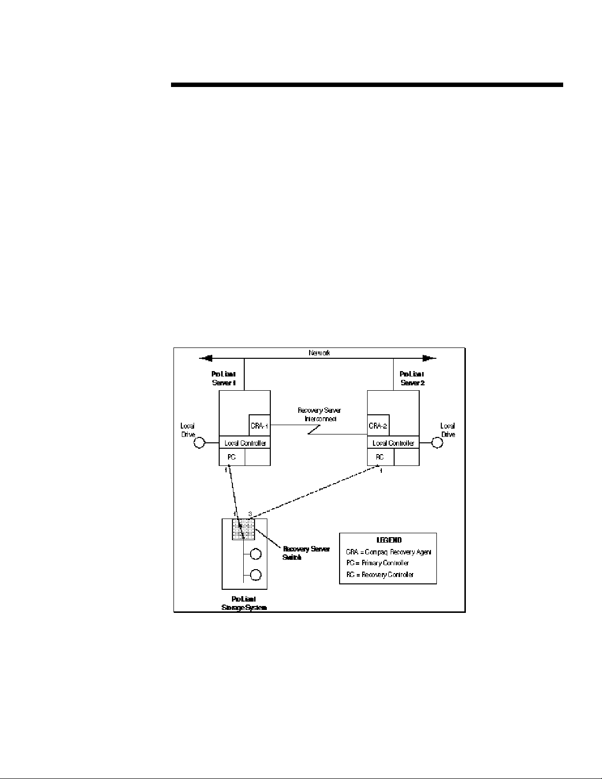
The primary and recovery servers are physically linked as shown in Figure 3 by the Recovery
.
.
.
Server Interconnect, a RS-232 serial cable with specific pinout connections required for the
.
.
.
Standby Recovery Server solution. The Recovery Server Interconnect is required for proper
.
.
.
operation.
.
.
.
.
NOTE: The Standby Recovery Server solution will NOT function with other serial
.
.
.
cables such as null modem cables.
.
.
.
.
.
The primary and recovery server’s hardware configuration should be identical down to the slot
.
.
.
number of each controller board. Theoretically the servers could differ in memory and CPU
.
.
.
configuration as these are dynamically determined by the Windows NT operating system during
.
.
.
the boot process. However, Compaq strongly recommends that the primary and recovery servers
.
.
have identical hardware configurations.
.
.
.
.
.
.
.
.
.
.
66
Page 7

WWHITE HITE PPAPERAPER (cont.)
.
.
Each server contains at least one SMART SCSI Array Controller or SMART-2 SCSI Array
.
.
.
Controller. SMART and SMART-2 Array Controllers can only be attached to disk drives that are
.
.
.
contained in external ProLiant Storage Systems that have the Recovery Server Switch installed.
.
.
.
Doc Number 465A/1196
Corresponding array controllers in primary and recovery servers that are connected to the same
.
.
.
ProLiant Storage System MUST be of the same type - either both SMART Array Controllers or
.
.
.
both SMART-2 Array Controllers. Corresponding array controllers in the primary and recovery
.
.
.
servers MUST have the same slot placement in each system.
.
.
.
.
Each server’s network interface controller (NIC) must be identical in type, slot placement, and
.
.
.
configuration. Integrated NICs can only be used if they are identical between the primary and
.
.
.
recovery servers. Otherwise, the integrated NIC must be disabled and identical NICs must be
.
.
.
installed in the same expansion slot number and identically configured in each server.
.
.
.
.
The Recovery Server Option Driver must be installed on the Windows NT Server configured as
.
.
.
the primary server. The Standby Recovery Server failure detection mechanism is based on the
.
.
.
Recovery Server Option Driver running on the primary server. As long as the recovery server
.
.
.
receives the heartbeat message within the time-out interval, it assumes that the primary server
.
.
.
has not failed. Any failure in the primary server that stops the Recovery Server Option Driver
.
.
.
from generating the periodic heartbeat message will be a detectable failure. The Recovery Server
.
.
.
Option Driver can be obtained from the Compaq Support Software Diskette for Microsoft
.
.
.
Windows NT (Windows NT SSD).
.
.
.
.
.
.
Normal Operation
.
.
.
.
.
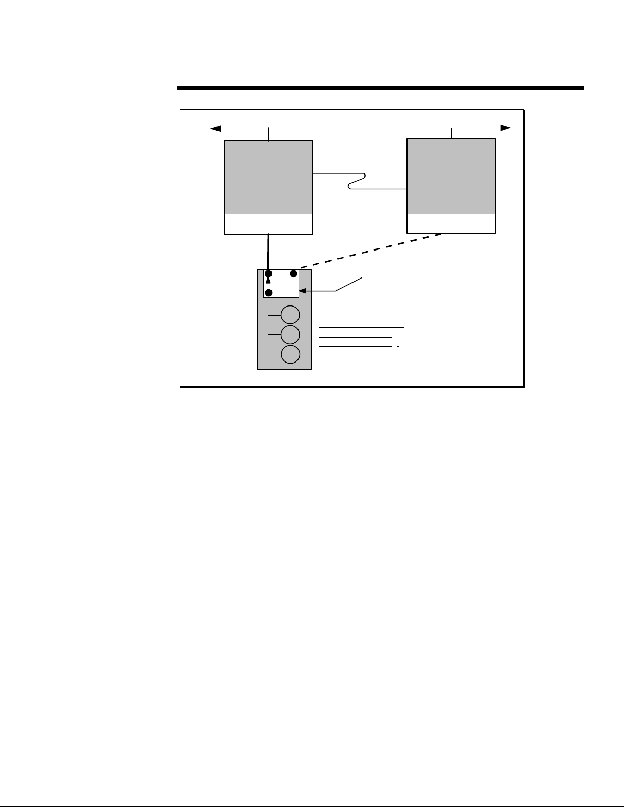
Figure 3 illustrates normal operation of Standby Recovery Server. Both the primary and recovery
.
.
.
servers are attached to the same network. The primary R/3-Database server supports users
.
.
.
attached to it via the network and the standby recovery server is idle.
.
.
.
.
Under normal operation, as soon as the recovery server has completed its power-on self test
.
.
.
(POST) sequence, it executes the Compaq Recovery Agent contained in the system ROM BIOS.
.
.
.
The Recovery Agent monitors a periodic “heartbeat message” transmitted by the Recovery Server
.
.
.
Option Driver to the recovery server via the Recovery Server Interconnect. At this point, no
.
.
.
operating system is loaded on the recovery server. Thus, the standby recovery server is
.
.
.
electronically attached to the network but is not accessible via the network. Its only function is to
.
.
.
wait for the R/3-Database server to fail.
.
.
.
.
The receipt of the heartbeat message within a configured time-out period indicates that the
.
.
.
R/3-Database server is functioning properly. The recovery server responds to each heartbeat
.
.
.
with an acknowledgment message across the serial connection. As long as the recovery server
.
.
.
continues to receive heartbeats according to schedule, it remains in the idle mode.
.
.
.
.
The Recovery Server Option is an extension of the Automatic Server Recovery (ASR) functions
.
.
.
currently supported in Compaq ProLiant servers. See the Compaq Hardware documentation that
.
.
.
came with the server for more information about ASR.
.
.
.
.
.
.
.
.
.
.
.
.
.
.
.
.
.
.
.
.
.
.
.
.
.
.
.
.
.
.
.
.
.
.
.
.
.
77
Page 8
WWHITE HITE PPAPERAPER (cont.)
.
.
.
.
.
.
.
.
.
.
Doc Number 465A/1196
.
.
.
.
.
.
.
.
.
.
.
.
.
.
.
.
.
.
.
.
.
.
R/3-Database Server
.
.
.
.
.
.
.
.
.
.
.
.
.
.
.
.
.
.
.
.
.
.
.
.
.
.
.
.
.
.
.
.
.
.
.
.
.
Figure 3. Standby Recovery Server—Normal Operation
.
.
.
.
.
.
.
Switchover Events
.
.
.
.
.
Switchover from the R/3-Database primary server to the standby recovery server occurs when
.
.
the R/3-Database server fails. If the recovery server does not receive a heartbeat message within
.
.
.
the time-out value set by the system configuration utility, the recovery server presumes that the
.
.
.
R/3- Database server has failed. (Loss of the heartbeat message could occur either because the
.
.
.
R/3- Database server has failed or because the connection of the Recovery Server Interconnect
.
.
.
cable has been broken.)
.
.
.
.
.
The switchover events occur as follows:
.
.
.
.
1. The Compaq Recovery Agent in the system ROM BIOS sends commands over the SCSI
.
.
.
.
.
.
.
.
.
.
.
.
.
.
.
.
.
.
.
.
.
.
.
.
.
.
.
.
.
.
.
.
.
.
.
.
.
.
.
.
.
.
.
.
.
.
.
.
.
.
.
.
.
bus to the Recovery Server Switch installed in the common set of ProLiant Storage
Systems. These commands cause the switch to disconnect the storage drives electrically
from the primary R/3-Database server and then to connect them electrically to the standby
recovery server.
2. The standby recovery server proceeds through a normal boot sequence using the disk
storage that was previously attached to the R/3-Database server.
3. Because the servers are identically configured, when the boot process is completed, the
recovery server assumes the logical network identity that was previously held by the
primary R/3-Database server.
4. The Application Server R/3 instances are restarted.
5. At this point, after restarting the database and R/3, the users can log on to R/3.
With the Compaq automated switchover process, the recovery server becomes the active server
and is back on-line in a matter of minutes, without administrator intervention.
R/3 and Database
Recovery Server
Option Driver
Windows NT
SMART-2
ProLiant
ProLiant Storage System
SCSI Cable
88
Network
Recovery Server
Interconnect
SCSI Cable
Recovery Server Switch
All storage is located
here and contains
database and R/3
System ROM BIOS
.
Recovery Agent
No OS loaded
SMART-2
Recovery Server
ProLiant
Page 9
WWHITE HITE PPAPERAPER (cont.)
.
.
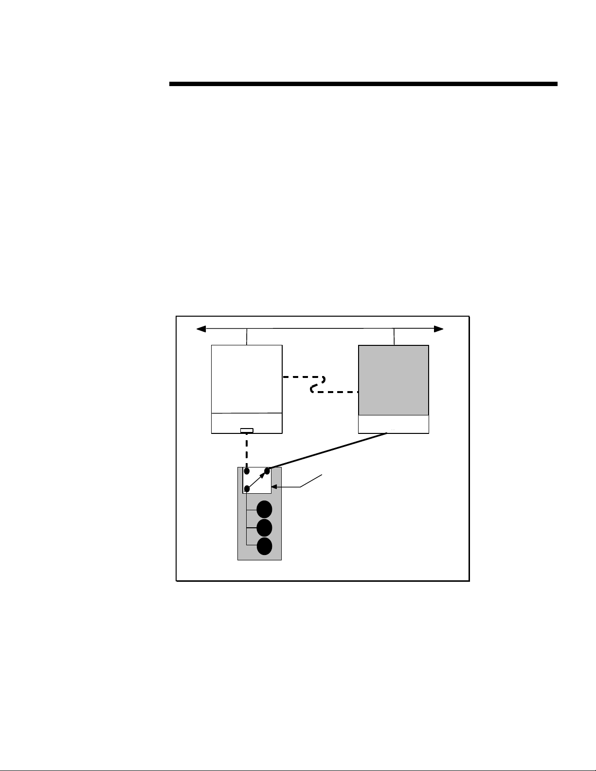
Figure 4 illustrates a standby recovery server configuration after the switchover has occurred.
.
.
.
The recovery server has assumed the function of the R/3-Database server. The R/3-Database
.
.
.
server has completed an ASR reboot and is waiting to be serviced. The effects of server failure
.
.
.
Doc Number 465A/1196
and switchover on clients are discussed later in this paper, in the section entitled “Client
.
.
.
Behavior.” See the Compaq Hardware documentation that came with the server for more
.
.
.
information about the ASR reboot.
.
.
.
.
If power is lost to both servers in a Standby Recovery Server configuration, the R/3-Database
.
.
.
server will not boot in an unattended manner when the power is restored. An external power
.
.
.
failure of this type will be recorded in the R/3-Database server NVRAM as a server failure
.
.
.
requiring service, not as a power outage. Thus, when the R/3-Database server is powered on, the
.
.
.
administrator is prompted to run diagnostics or to press F8F8 to continue a normal boot sequence.
.
.
.
This illustrates the importance of an uninterruptible power supply.
.
.
.
.
If the system is unattended when the power is restored, the recovery server times out, switches the
.
.
.
storage disks, and boots from the disks because the R/3-Database server is not sending the
.
.
.
heartbeat message to the standby server.
.
.
.
.
.
.
.
.
.
.
.
.
.
.
.
.
.
.
.
.
.
.
.
.
.
.
.
.
.
.
.
.
.
.
.
.
.
.
.
Failed Server
.
.
.
.
.
.
.
.
.
.
.
.
.
.
.
.
.
.
.
.
.
.
.
.
.
.
.
.
.
.
.
.
.
.
.
.
.
.
.
Figure 4. Standby Recovery Server—After Switchover
.
.
.
.
.
.
.
.
.
.
.
.
.
.
.
.
.
.
.
.
.
.
.
.
.
.
.
.
.
.
.
.
.
Waiting for Service,
No OS loaded
System ROM BIOS
SMART-2
ProLiant
ProLiant Storage System
SCSI Cable
Network
Recovery Server
Interconnect
SCSI Cable
Recovery Server Switch
99
R/3 and SQL
Windows NT
SMART-2
R/3-SQL Server
ProLiant
Page 10

WWHITE HITE PPAPERAPER (cont.)
.
.
.
.
.
.
Switchover Time
.
.
.
.
The Standby Recovery Server is designed for business-critical servers that cannot sustain
Doc Number 465A/1196
.
.
.
periods of downtime exceeding several minutes. The time required for the recovery server to
.
.
.
assume the function of the R/3-Database server is the sum of the following six factors:
.
.
.
.
1. The time that elapses from the moment at which a failure occurs in the primary processor to
.
.
.
.
.
.
.
.
.
.
.
.
.
.
.
.
.
.
.
.
.
.
.
.
.
.
.
.
.
.
.
.
.
.
.
.
.
.
.
.
.
.
.
.
.
.
.
.
.
.
.
.
.
.
.
.
.
.
.
.
.
.
.
.
.
.
.
.
.
.
.
.
.
.
.
.
.
.
.
.
.
.
.
.
.
.
.
.
.
.
.
.
.
.
.
.
.
.
.
.
.
.
.
.
.
.
.
.
.
.
.
.
.
.
.
.
.
.
.
.
.
.
.
.
.
.
.
.
.
.
.
.
.
.
.
.
.
the moment at which that failure manifests itself in the loss of a heartbeat message. This
time period may be very short (a few seconds) in the case of catastrophic failures such as
loss of the processor, or it may be relatively long (several minutes) in the case of certain
software failures.
2. The defined time-out period that the Recovery Agent in the system ROM BIOS waits for a
heartbeat message before initiating a switchover is the ASR time-out value. It is set in the
system configuration with a default value of 10 minutes. Available values range from 5 to 30
minutes.
3. Once a switchover has been initiated, the time required to initialize the SMART
Controllers and begin the Windows NT operating system boot process from the drives,
which by this time are electrically connected to the recovery server. This is typically
between 2 and 4 minutes.
4. The time required for the Windows NT operating system to boot. This is dependent upon
the size and number of disk drives that are attached, but is usually accomplished within 3
minutes.
5. The time required for the database to start and recover from the previous failure once the
Windows NT operating system is active and the time required for R/3 to start and be
available to users. This phase depends on the length of the database recovery period, which
is difficult to predict, but generally takes less than 5 minutes.
6. The time for the users to login.
Faults
Many factors affect server operation. In the Standby Recovery Server configuration, several types
of faults can occur such as the following:
• Failures of the R/3-Database server, the types of faults for which the Recovery Server Option
was designed
• Loss of heartbeat resulting from serial cable problems, not from server problems
• Failures that affect operation of the R/3-Database server but do not cause a switchover
1010
Page 11

WWHITE HITE PPAPERAPER (cont.)
.
.
.
.
.
Failure DetectionFailure Detection
.
.
.
.
The failure detection mechanism in the Standby Recovery Server is based on the Recovery Server
.
Doc Number 465A/1196
.
.
Option Driver software that runs in the R/3-Database server. As long as the recovery server
.
.
.
receives the heartbeat message within the time-out period, it presumes that the R/3-Database
.
.
.
server has not failed. Any failure in the R/3-Database server that stops the Recovery Server
.
.
.
Option Driver from generating the periodic heartbeat message will be a detectable failure.
.
.
.
Examples of detectable failures include:
.
.
.
.
• Catastrophic and unrecoverable hardware failure in the R/3-Database server such as loss of
.
.
.
.
.
.
.
.
.
.
.
.
.
.
.
.
.
.
.
.
.
.
.
.
.
.
.
.
.
.
.
.
.
.
.
.
.
.
.
.
.
.
.
.
.
.
.
.
.
.
.
.
.
.
.
.
.
.
.
.
.
.
.
.
.
.
.
.
.
.
.
.
.
.
.
.
.
.
.
.
.
.
.
.
.
.
.
.
.
.
.
.
.
.
.
.
.
.
.
.
.
.
.
.
.
.
.
.
.
.
.
.
.
.
.
.
.
.
.
.
.
.
.
.
.
.
.
.
.
the processor or uncorrectable memory errors
• Loss of the R/3-Database server power supply
Generally, any failure that is detected by ASR will be detected and acted upon by the recovery
server.
NOTE: There is a class of failures that causes the R/3-Database server to malfunction
without causing loss of the heartbeat message. For example, failure of the Network
Interface Controller could render the R/3-Database server unusable, but the Recovery
Server Option Driver would still send the heartbeat message to the recovery server.
Failures of this type cannot be detected by the recovery server; therefore, an automatic
switchover will not occur. Generally, the failures detected by the recovery server are the
same ones that are detected by the ASR mechanism.
Potential Interconnect FailuresPotential Interconnect Failures
The Recovery Server Interconnect can experience three types of failures. These failures and the
behavior they cause are described as follows.
NOTE: This discussion assumes that Compaq Insight Manager is being used.
• R/3-Database Server Cable Failure
If the Recovery Server Interconnect is disconnected from the R/3-Database server, the
recovery server cannot receive the heartbeat message. The Recovery Server Option Driver
in the R/3-Database server can detect this condition. It sends an Insight Manager alarm
indicating that the R/3-Database server has detected a cable fault and that it is shutting
down the Windows NT operating system in anticipation of the switchover that will occur
because the recovery server is no longer receiving the heartbeat message.
• Recovery Server Cable Failure
If the Recovery Server Interconnect is disconnected from the recovery server, the recovery
server detects this condition and does not attribute loss of the heartbeat message to failure of
the R/3-Database server. Because the R/3-Database server can no longer receive the
acknowledgment message from the recovery server, however, the R/3-Database server sends
an Insight Manager alarm indicating possible failure of the recovery server.
• Damaged Cable
If the Recovery Server Interconnect is physically cut, the heartbeat message and the
acknowledgment message cannot travel between the R/3-Database server and the recovery
server. Loss of the acknowledgment message causes the R/3-Database server to send an
Insight Manager alarm indicating possible failure of the recovery server. Meanwhile, loss of
the heartbeat message for longer than the time-out period causes the recovery server to
switch the storage disks from the R/3-Database server to the recovery server and then boot.
1111
Page 12

WWHITE HITE PPAPERAPER (cont.)
.
.
Upon failure, the R/3-Database server normally becomes totally inactive. In the case of a
.
.
.
.
.
.
.
.
Doc Number 465A/1196
.
.
.
.
.
.
.
.
.
.
.
.
.
.
.
.
.
.
.
.
.
.
.
.
.
.
.
.
.
.
.
.
.
.
.
.
.
.
.
.
.
.
.
.
.
.
.
.
.
.
.
.
.
.
.
.
.
.
.
.
.
.
.
.
.
.
.
.
.
.
.
.
.
.
.
.
.
.
.
.
.
.
.
.
.
.
.
.
.
.
.
.
.
.
.
.
.
.
.
.
.
.
.
.
.
.
.
.
.
.
.
.
.
.
.
.
.
.
.
.
.
.
.
.
.
.
.
.
.
.
.
.
.
.
.
.
.
.
.
.
.
.
.
.
.
.
.
damaged cable, however, the R/3-Database server continues running after its connection to
the storage disks has been lost and the recovery server has booted. The Windows NT
operating system on the R/3-Database server can no longer function correctly, but the
network protocol portion of the Windows NT operating system is still active.
When the recovery server boots, it presents the same network identification as that used by
the original R/3-Database server. As a result, network clients might not be able to log in to
the server because both the primary and recovery servers are using the same network
identification.
This type of failure is unlikely and is preventable with simple precautionary steps to protect
the serial cable and its connections. Screw the serial cable down securely; and for maximum
cable protection, rack mount the servers.
Servicing the Failed Server
To re-establish Standby Recovery Server operation after a switchover, a failed R/3-Database
server must be repaired or replaced and brought back on-line. The Standby Recovery Server
makes it possible for the system administrator to schedule service on the R/3-Database server at
a convenient time while the recovery server is active. The R/3-Database server hardware can be
serviced on site or off site.
Once a switchover occurs, no drives are electrically attached to the disk controllers in the
R/3-Database server For this reason, there might be some constraints on diagnostic activities
that can be performed on the failed R/3-Database server on site. However, by disconnecting the
R/3-Database server from the Recovery Server Interconnect and adding other drives to the
R/3-Database server, full on-site diagnosis can be performed on the failed R/3-Database server
while the recovery server is running, The failed R/3-Database server can also be disconnected
from the recovery server and the ProLiant Storage System and moved off site for service.
Restoring the Configuration After Switchover
After the R/3-Database server has been serviced or replaced, restore the original configuration.
The recovery server and ProLiant Storage Systems must be power cycled to reinitialize the
Recovery Server Switch. The disk drives will be electrically connected to the original R/3Database server and it will boot the Windows NT operating system. The recovery server will
return to its role of listening for the heartbeat message from the R/3-Database server.
After setting up and configuring both the primary and recovery servers, verify that both servers
operate correctly and will switch over when needed.
Client Behavior
When a failure of the R/3-Database server occurs, users attached to it experience a service
outage. The length of this outage is described previously in section “Switchover Time.” The
symptoms experienced by the users vary depending on whether their dialog instance was on the
R/3-Database server or on a dedicated application server. In the former case, an error message
displays, communicating to the user that the application server has been shutdown. In the latter
case, the SAPGUI will become unresponsive.
1212
Page 13

WWHITE HITE PPAPERAPER (cont.)
.
.
.
.
.
.
Disk Subsystem Considerations
.
.
.
.
The following sections discuss disk subsystem considerations, which include disk integrity, disk
Doc Number 465A/1196
.
.
.
volume configuration for Windows NT, and performance considerations.
.
.
.
.
Disk IntegrityDisk Integrity
.
.
.
.
.
Failure of the R/3-Database server can be caused by several different conditions ranging from
.
.
.
software faults in the Windows NT operating system to hardware failure. Depending on the
.
.
.
nature of the fault and the disk activities occurring at the time of the fault, the disk data
.
.
structures can be corrupted and might require corrective processing before the recovery server
.
.
.
boots the Windows NT operating system. In Microsoft Windows NT 3.5x, the disk integrity
.
.
.
check and corrective processing are performed automatically.
.
.
.
.
.
.
Disk Volume Configuration for Windows NT 3.5XDisk Volume Configuration for Windows NT 3.5X
.
.
.
.
.
Compaq recommends that the NTFS file system be used for all Windows NT disk partitions.
.
.
Additionally, Compaq recommends that the Windows NT system disk and other executables be
.
.
.
placed on a separate SMART or SMART-2 controller logical drive. Use other logical drives to
.
.
.
store data.
.
.
.
.
.
.
Performance ConsiderationsPerformance Considerations
.
.
.
.
.
In a Standby Recovery Server configuration, the Array Accelerator, which serves as a read/write
.
.
cache for I/O requests directed to the SMART or SMART-2 Array Controller, must be disabled
.
.
.
when using a SMART controller or changed to 100% read cache when using a SMART-2
.
.
.
controller.
.
.
.
.
.
For the SMART controller, the Compaq System Configuration Utility automatically disables the
.
.
.
Array Accelerator when the SMART controller is attached to switchable disks in a Standby
.
.
.
Recovery Server configuration. For the SMART-2 controller, the Compaq Array Configuration
.
.
.
Utility automatically changes the Array Accelerator to 100% read cache when the SMART-2
.
.
.
controller is attached to switchable disks in a Standby Recovery Server configuration.
.
.
.
.
The system performance impact of changing the Array Accelerator configuration is determined
.
.
.
by the interaction of the controllers with software and other hardware in the system and by tuning
.
.
.
of the system. As a result, the performance of the overall system(s) needs to be considered to
.
.
.
determine if adjustments are required to compensate for this factor. In certain cases, changing the
.
.
.
Array Accelerator configuration will degrade system(s) performance.
.
.
.
.
For example, the database might be tuned so that it is processor constrained and not I/O
.
.
.
constrained. In this case, enabling or disabling the SMART Controller Array Accelerator would
.
.
.
have little effect on overall system performance. However, an I/O-constrained system, disabling
.
.
.
the Array Accelerator would lower the system performance. In all cases, system performance
.
.
.
should be considered when planning for a Standby Recovery Server configuration.
.
.
.
.
.
.
.
.
.
.
.
.
.
.
.
.
.
.
.
.
.
.
.
.
.
.
.
.
.
.
.
.
.
.
1313
Page 14

WWHITE HITE PPAPERAPER (cont.)
.
.
.
.
SETTING UP A STANDBY RECOVERY SERVER
.
.
.
.
.
The following sections discuss setting up a Standby Recovery Server, which include information
.
Doc Number 465A/1196
.
.
on system configuration, testing the configuration, and R/3- Database specific settings.
.
.
.
.
.
.
System Configuration
.
.
.
.
.
The primary and the recovery server must have identical hardware configurations, including
.
.
identical slot locations of all controller boards. Anytime there is a change to both the primary and
.
.
.
the recovery server, you must run the Compaq System Configuration Utility on each system.
.
.
.
.
.
NOTE: When configuring the SMART controller that is connected to the Recovery
.
.
.
Server Switch, set the Array Accelerator Status to Disabled on both the primary server
.
.
.
and the recovery server. When configuring the SMART-2 controller that is connected to
.
.
.
the Recovery Server Switch, set the Array Accelerator to 100% read cache on both the
.
.
.
primary server and the recovery server. Failure to properly configure the Array
.
.
.
Accelerators could result in the disk drives attached to the controller becoming corrupted
.
.
after returning to the primary server from the recovery server.
.
.
.
.
.
When configuring the recovery server, be sure to set the ASR time-out value higher than the total
.
.
.
time required for the primary server to boot and become operational.
.
.
.
.
A finite amount of time is required for the primary server to boot from the operating system and
.
.
.
become operational. If the Automatic Server Recovery (ASR) time-out value is set for less than
.
.
.
that amount of time, then the recovery server times out and triggers a switchover, even though no
.
.
.
server failure has occurred.
.
.
.
.
If the original, verified system configuration is changed, it is necessary to reconfigure the system
.
.
.
and to verify that the new configuration is correct. For example, if you add a disk drive, you must
.
.
.
reconfigure the system.
.
.
.
.
.
To reconfigure the system, follow these steps:
.
.
.
.
1. Shut down the application software and operating system on the primary server.
.
.
.
.
.
2. Turn off the primary server.
.
.
.
.
3. Turn off the recovery server.
.
.
.
.
4. Turn off the ProLiant Storage System(s).
.
.
.
.
.
5. Make the hardware changes: Add or remove disks, add or remove adapter cards, etc.
.
.
.
.
6. Power on the ProLiant Storage System(s).
.
.
.
.
.
7. Power on the primary server.
.
.
.
.
8. Run the System Configuration Utility to configure the primary server if necessary. If using a
.
.
.
.
.
.
.
.
.
.
.
.
.
.
.
.
.
.
.
.
.
.
.
.
.
.
.
.
.
.
.
.
.
.
.
.
SMART Controller, ensure that the Array Accelerators are disabled. If using a SMART-2
Controller, ensure that the Array Accelerators are set to 100% read cache.
NOTE: If you are using a SMART-2 Controller and you have made changes to the disk
configuration, you will need to run the Compaq Array Configuration Utility to configure the
Array Accelerator setting.
9. Verify that the application software and the operating system are functioning correctly.
10. Shut down the application software and the operating system on the primary server.
11. Turn off the primary server.
1414
Page 15

WWHITE HITE PPAPERAPER (cont.)
.
.
12. Turn on the recovery server.
.
.
.
.
.
13. Press the F8 key on the recovery server to switch the storage disks manually to the
.
.
.
Doc Number 465A/1196
.
.
.
.
.
.
.
.
.
.
.
.
.
.
.
.
.
.
.
.
.
.
.
.
.
.
.
.
.
.
.
.
.
.
.
.
.
.
.
.
.
.
.
.
.
.
.
.
.
.
.
.
.
.
.
.
.
.
.
.
.
.
.
.
.
.
.
.
.
.
.
.
.
.
.
.
.
.
.
.
.
.
.
.
.
.
.
.
.
.
.
.
.
.
.
.
.
.
.
.
.
.
.
.
.
.
.
.
.
.
.
.
.
.
.
.
.
.
.
.
.
.
.
.
.
.
.
.
.
.
.
.
.
.
.
.
.
.
.
.
.
.
.
.
.
.
.
recovery server.
14. Run the System Configuration Utility to configure the recovery server if necessary. Verify
that all SMART Controller Array Accelerators are disabled. Verify that all SMART-2
Controller Array Accelerators are set to 100% read cache.
NOTE: If you are using a SMART-2 Controller and you have made changes to the disk
configuration, you will need to run the Compaq Array Configuration Utility to configure the
Array Accelerator setting.
15. Verify that the application software and the operating system are functioning correctly.
16. Shut down the application software and the operating system on the recovery server.
17. Turn off the recovery server.
18. Turn off the ProLiant Storage System(s).
19. Turn on the ProLiant Storage System(s).
20. Turn on the primary server.
21. Turn on the recovery server.
22. The primary server should boot. The recovery server should begin monitoring the
primary server.
23. Test the configuration to verify that it will switch over properly to the recovery server.
Testing the Configuration
Once you have set up and configured both the primary and recovery servers, you must verify that
both servers operate correctly and will switchover when needed. You can use two methods to
perform a switchover test, which are:
• Recommended Switchover Test
• Alternate Switchover Test
Recommended Switchover Test MethodRecommended Switchover Test Method
Compaq recommends testing a configuration by powering down the primary server while the
operating system is running. This allows the recovery server to detect that the primary server is
not available, to switch access to the storage disks from the primary server to the recovery server,
and to boot the operating system on the recovery server.
To perform this test, turn off the primary server while it is active with the operating system and
applications. After the recovery server ASR time-out period expires, the recovery server switches
the storage system(s) from the primary to the recovery server. The recovery server then boots
from the storage disks. This test verifies the configuration and demonstrates the effect of the
failure and switchover event.
Alternate Switchover Test MethodAlternate Switchover Test Method
You can also perform a manual switchover from the primary server to the recovery server.
1515
Page 16

WWHITE HITE PPAPERAPER (cont.)
.
.
.
.
To perform this test, follow these steps:
.
.
.
.
1. Shut down the operating system and power off the system on the primary server.
.
.
.
Doc Number 465A/1196
.
.
.
2. Press the F8 key while this message displays on the recovery server:
.
.
.
.
.
.
.
.
.
.
.
.
.
.
.
.
.
.
.
.
.
.
.
.
.
.
.
.
.
.
.
.
.
.
.
.
.
.
.
.
.
.
.
.
.
.
.
.
.
.
.
.
.
.
.
.
.
.
.
.
.
.
.
.
.
.
.
.
.
.
.
.
.
.
.
.
.
.
.
.
.
.
.
.
.
.
.
.
.
.
.
.
.
.
.
.
.
.
.
.
.
.
.
.
.
.
.
.
.
.
.
.
.
.
.
.
.
.
.
.
.
.
.
.
.
.
.
.
.
.
.
.
.
.
.
.
.
.
.
.
.
.
.
Press F8 to switch now.
3. Press the Y key to confirm your selection on the recovery server.
After a brief period, the recovery server boots the operating system and assumes the role of the
primary server. If the recovery server does not boot, check your configuration and repeat the test.
R/3 Software Specific Settings
Because of the application-independence of this solution, no special SAP R/3 Database specific
configuration is required. Of course the surviving application server has to stop and start their
SAP application services to bind to the physical different machine. However, ensure that R/3 and
the database automatically start at boot time so that after a switchover no intervention is required.
You can ensure this by developing a script to perform the necessary tasks and installing it as a
service with Automatic startup. You can set this up with a Microsoft Windows NT Resource Kit
tool called SRVANY.
The following steps describe the installation procedure:
1. Copy SRVANY.EXE to your system and install it as a Windows NT service with a
meaningful name, for example:
INSTSRV R3UP c:\reskit35\srvany.exe
2. Configure as automatic via the Services applet ("Startup..." dialog) of the Control Panel.
3. Set the account for the service (the SAP administrator) via the Services applet ("Startup..."
dialog) of the Control Panel.
4. Run the Registry Editor (REGEDT32.EXE):
a) Create a “Parameters” key under the following:
KEY_LOCAL_MACHINE\SYSTEM\CURRENTCONTROLSET\SERVICES\R3UP
b) Under the Parameters key, create an “Application” value of type REG_SZ and specify
there the full path of your application executable (including the extension). For example:
Application: REG_SZ: C:\WINNT35\SYSTEM32\R3UP.BAT
1616
Page 17

WWHITE HITE PPAPERAPER (cont.)
.
.
.
.
The R/3 and database startup scripts could be similar to the following:
.
.
.
echo off
.
.
.
cls
Doc Number 465A/1196
.
.
.
rem Windows NT Resource Kit must be installed on all servers
.
.
.
REM Stopping the R/3 Instance on other application servers
.
.
.
d:\usr\sap\cpq\sys\exe\run\sapsrvkill CPQAPP2_CPQ_05
.
.
.
........
.
.
.
rem CHANGE DIRECTORY AND SERVICE NAMES ACCORDING TO YOUR
.
.
.
CONFIGURATION
.
.
.
rem Add one pair of lines similar to the following per application server
.
.
.
netsvc SAPOsCol \\CPQAPP /start 2>&1 > c:\users\cpqadm\r3up.log
.
.
.
netsvc SAPCPQ_05 \\CPQAPP /start 2>&1 > c:\users\cpqadm\r3up.log
.
.
.
.
.
rem Starting SAP R/3 on DB server
.
.
.
rem CHANGE PATHS AND PROFILE NAMES ACCORDING TO YOUR CONFIGURATION
.
.
.
d:\usr\sap\CPQ\sys\exe\run\sapstart pf=d:\usr\sap\CPQ\sys\profile\START_DVEBMGS00 2>&1
.
.
.
>> c:\users\cpqadm\r3up.log
.
.
.
.
.
.
rem Starting SAP R/3 on App. servers.
.
.
.
rem CHANGE PATHS AND PROFILE NAMES ACCORDING TO YOUR CONFIGURATION
.
.
.
d:\usr\sap\CPQ\sys\exe\run\sapstart pf=d:\usr\sap\CPQ\sys\profile\CPQ_D05
.
.
.
SAPDIAHOST=CPQAPP 2>&1 >> c:\users\cpqadm\r3up.log
.
.
.
exit
.
.
.
Sample Automatic Start-Up Command File: R3UP.BAT
.
.
.
.
.
NOTE: Two licenses need to be ordered for the SAP R/3 system, since the license key
.
.
.
is issued for a specific customer key. The customer key is based on information specific
.
.
to the server where “saplicense - get” is executed.
.
.
.
.
.
.
.
.
ON-LINE R ECOVERY SERVER TECHNOLOGY
.
.
.
.
The On-Line Recovery Server configuration pairs two independently operating Compaq ProLiant
.
.
.
Servers as automatic, hot standbys for each other. The two active servers are interconnected via
.
.
.
the Recovery Server Interconnect cable so that ProLiant Storage Systems attached to either server
.
.
.
remain accessible to clients even if one server fails. The Recovery Server Interconnect is a RS-
.
.
.
232 serial cable with specific pinout connections required for the On-Line Recovery Server
.
.
.
solution. The Recovery Server Interconnect is required for the proper operation of the On-Line
.
.
.
Recovery Server solution. The solution will NOT function with other serial cables such as null
.
.
.
modem cables.
.
.
.
.
The Recovery Server Option Driver must be installed on the Windows NT Servers configured in
.
.
.
the On-Line Recovery Server partnership. The failure detection mechanism is based on the
.
.
.
Recovery Server Option Driver running on the servers. As long as the recovery server receives
.
.
.
the heartbeat message within the time-out interval, it assumes that the primary server has not
.
.
.
failed. Any failure in the primary server that stops the Recovery Server Option Driver from
.
.
.
generating the periodic heartbeat message will be a detectable failure. The Recovery Server
.
.
.
Option Driver can be obtained from the Compaq Support Software Diskette for Microsoft
.
.
.
Windows NT (Windows NT SSD).
.
.
.
.
.
.
.
.
.
.
.
.
.
.
.
.
.
1717
Page 18
WWHITE HITE PPAPERAPER (cont.)
.
.
.
.
If one server fails, the ProLiant Storage System(s) attached to the failed server automatically
.
.
.
switches over to the surviving server via the Recovery Server Switch—without administrator
.
.
intervention. The Recovery Server Switch is an electrically controlled SCSI switch that must be
.
Doc Number 465A/1196
.
.
installed in each switchable Compaq ProLiant Storage System.
.
.
.
.
.
When the switchover of the shared drives occurs, the operating system on the surviving server
.
.
.
need not be restarted. Selected applications running on the surviving server are notified of the
.
.
.
switchover. As a result, clients of the failed server can quickly regain access to their data and
.
.
.
programs from the surviving server.
.
.
.
.
NOTE: A variety of configurations are possible with the On-Line Recovery Server. The
.
.
.
configuration which Compaq recommends in SAP R/3 environments is the
.
.
.
“asymmetrical configuration.” In this configuration, switchover only takes place in one
.
.
.
direction, from the R/3 database server to another server.
.
.
.
.
Because all configurations work in a similar fashion, the easiest way to understand how the On-
.
.
.
Line Recovery Server works is to look at an example. Figure 6 illustrates a pre-switchover
.
.
.
asymmetrical configuration in which only one of the paired servers has switchable external
.
.
.
storage. The servers switch in only one direction. The primary and recovery controllers are
.
.
.
standard SMART Controllers which perform the specified roles.
.
.
.
.
.
.
.
.
.
.
.
.
.
.
.
.
.
.
.
.
.
.
.
.
.
.
.
.
.
.
.
.
.
.
.
.
.
.
.
.
.
.
.
.
.
.
.
.
.
.
.
.
.
.
.
.
.
.
.
.
.
.
.
.
.
.
.
.
.
.
.
.
.
.
Figure 6. Normal Operation of an Asymmetrical Configuration Before Switchover
.
.
.
.
.
.
.
.
Figure 7 illustrates the pair after a switchover.
.
.
.
.
.
.
.
.
.
.
.
.
.
.
.
.
.
.
.
.
1818
Page 19

WWHITE HITE PPAPERAPER (cont.)
.
.
.
.
.
.
.
.
.
.
Doc Number 465A/1196
.
.
.
.
.
.
.
.
.
.
.
.
.
.
.
.
.
.
.
.
.
.
.
.
.
.
.
.
.
.
.
.
.
.
.
.
.
.
.
.
.
.
.
.
.
.
.
.
.
.
.
.
.
.
.
.
.
.
Figure 7. An Asymmetrical Switchover Configuration
.
.
.
.
.
Two things about this configuration are particularly important:
.
.
.
.
1. The ProLiant Storage System(s) are not shared by the two servers. That is, they are not
.
.
.
.
.
.
.
.
.
.
.
.
.
.
.
.
.
.
.
.
.
.
.
.
.
.
.
.
.
.
.
.
.
.
.
.
.
.
.
.
.
.
.
.
.
.
.
.
.
.
.
.
.
.
.
.
.
.
.
.
.
.
.
.
.
.
.
.
.
.
.
.
.
.
.
.
.
.
.
.
electrically connected to both servers at the same time.
2. A Recovery Server Switch must be installed in each switchable ProLiant Storage System.
IMPORTANT: If the primary controller is a SMART Array Controller, the recovery controller connected
to the same ProLiant Storage System must also be a SMART Array Controller. If the primary controller is
a SMART-2 Array Controller, the recovery controller connected to the same ProLiant Storage System
must also be a SMART-2 Array Controller. SMART and SMART-2 Array Controllers MUST NOT be mixed
when connected to the same storage system.
For each SMART Controller involved in switchover in the Primary Server there has to be a
corresponding SMART Controller in the Recovery Server.
• The SMART controller in the Primary Server , called Primary Controller, connects the
Primary Server to its own switchable ProLiant Storage System during normal operation.
During normal operation. the data flow to/from the switchable ProLiant Storage System takes
place via the Primary Controller.
• The SMART controller in the Recovery Server, called Recovery Controller, is only
electrically connected to the switchable ProLiant Storage System AFTER the fail-over has
occurred. Now, after the fail-over the data flow to and from the switchable ProLiant Storage
System takes place via the Recovery Controller.
1919
Page 20

WWHITE HITE PPAPERAPER (cont.)
.
.
.
.
Each SMART Controller has two ports for SCSI connectors and can support either one or two
.
.
.
ProLiant Storage System(s). For each Primary Controller in the Primary Server there must be
.
.
an associated Recovery Controller in the paired server. Therefore, if one or both servers in an
.
Doc Number 465A/1196
.
.
On-Line Server Pair have more than two switchable ProLiant Storage Systems, you need
.
.
.
additional SMART Controllers.
.
.
.
.
.
A local controller in one or both paired servers can be a SMART Controller. However, this local
.
.
.
controller cannot be connected to a switchable ProLiant Storage System. In the On-line Recovery
.
.
.
Server configuration SMART controllers have to be exclusively dedicated to switchable ProLiant
.
.
.
Storage Systems and their function cannot be split between local storage and switchable storage.
.
.
.
.
The serial ports of the two paired servers are connected by a Recovery Server Interconnect cable.
.
.
.
Each server runs a Compaq Recovery Agent (CRA), software that communicates with its
.
.
.
counterpart in the other server via this cable.
.
.
.
.
To indicate that the server is still on-line and operating normally, the CRA periodically transmits
.
.
.
a heartbeat message to the CRA in the paired server. Each CRA listens for heartbeats from the
.
.
.
other server. If it receives the expected heartbeat, the CRA transmits an acknowledgment
.
.
.
message to the other CRA. If the expected heartbeat is not received within the time-out interval
.
.
.
defined in the System configuration, the CRA presumes that the other server has failed and
.
.
.
initiates a switchover.
.
.
.
.
An LED indicator located on the back of each ProLiant Storage System indicates if a switchover
.
.
.
has occurred. During normal operation the LED glows green. It changes to amber if the storage
.
.
.
system is switched over to the other server.
.
.
.
.
.
.
.
.
.
.
.
.
.
.
.
.
.
.
.
.
.
.
.
.
.
.
.
.
.
.
.
.
.
.
.
.
.
.
.
.
.
.
.
.
.
.
.
.
.
.
.
.
.
.
.
.
.
.
.
.
.
.
.
.
.
.
.
.
.
.
.
.
.
.
.
.
.
.
.
.
.
.
.
.
.
.
.
.
.
2020
Page 21

WWHITE HITE PPAPERAPER (cont.)
.
.
.
.
.
.
SAP R/3 IMPLEMENTATION CONSIDERATIONS FOR ON-LINE
.
.
.
RECOVERY SERVER
.
Doc Number 465A/1196
.
.
.
When a site has more than one server, either because the R/3 platform is distributed or because
.
.
.
there are other Compaq servers, it could be possible to set up one of them as the On-Line
.
.
.
Recovery Server for the database or R/3 server. It should be carefully considered whether the
.
.
.
availability of the candidate Recovery Server is guaranteed. It might happen that a test server
.
.
.
that plays the role of Recovery Server is temporarily out of order because of a running test. If the
.
.
.
Primary Server fails at that time, the switchover would not take place and R/3 would not be
.
.
.
restarted and made available to users. Besides, a test server is very likely to have a different
.
.
.
operating system version, which might make the switchover not work. Therefore Compaq
.
.
.
recommends not to use a test server as a recovery server. The wisest choice would be to
.
.
.
configure one of the application servers as Recovery Servers. Application servers are
.
.
.
normally available and not used for purposes other than running the R/3 system. In these
.
.
.
scenarios, it is also possible to dedicate an additional server exclusively as a Standby or
.
.
.
On-Line Recovery Server.
.
.
.
.
The configuration of the On-Line Recovery Server has a number of implications which must be
.
.
.
considered before implementing the solution, which are:
.
.
.
.
• Disk Layout of the R/3- Database Server
.
.
.
.
.
.
.
.
.
.
.
.
.
.
.
.
.
.
.
.
.
.
.
.
.
.
.
.
.
.
.
.
.
.
.
.
.
.
.
.
.
.
.
.
.
.
.
.
.
.
.
.
.
.
.
.
.
.
.
.
.
.
.
.
.
.
.
.
.
.
.
.
.
.
.
.
.
.
.
.
.
.
.
.
.
.
.
.
.
.
.
.
.
.
.
.
.
The SAP and used database software, as well as the database owned data and log files,
should be located in partitions on disks in external storage cabinets so that they can be
switched over after a server failure. The Windows NT operating system should be on an
independent disk or logical volume that could be either internal or external, but not
switchable. Although On-line Recovery Server supports drive letter change after a
switchover, it is desirable for the sake of simplicity, to avoid such a situation by making sure
that letters assigned to the recovery server drives do not match those of the switchable drives
of the primary server.
• Processing Requirements
If the recovery server has less processing power than the R/3-Database server, the recovery
server could not support the same load and number of users. The situation would be even
worse if the recovery server must still perform its normal role. Compaq recommends
configuring the recovery server with at least the same number and types of processors, and
suspending its normal role while it functions as an R/3-Database server. Alternatively,
because the switchover is a momentary situation, users might be willing to accept a certain
amount of performance degradation. In this case alternative profiles for the R/3 instance
should be prepared according to the less powerful configuration of the recovery server.
• Memory Capacity
After the switchover occurs, the recovery server supports the database instance (with all
related services) and the R/3 instance. This requires as much memory as there was before on
the failed R/3-Database server if the performance level is to be maintained.
• Page File Size
As a result of the previous point, the page file(s) of the recovery server should be large
enough to accommodate the paging needs of the database and R/3.
• Backup Devices
Typically, the R/3-Database server has the necessary backup devices to back up its own disks
and those of the other server(s). The recovery server might be equipped with some backup
devices to allow it to perform incremental backups while the R/3-Database server is down.
2121
Page 22

WWHITE HITE PPAPERAPER (cont.)
.
.
• Primary Domain Controller Setup
.
.
.
.
.
.
.
.
Doc Number 465A/1196
.
.
.
.
.
.
.
.
.
.
.
.
.
.
.
.
.
.
.
.
.
.
.
.
.
.
.
.
.
.
.
.
.
.
.
.
.
.
.
.
.
.
.
.
.
.
.
.
.
.
.
.
.
.
.
.
.
.
.
.
.
.
.
.
.
.
.
.
.
.
.
.
.
.
.
.
.
.
.
.
.
.
.
.
.
.
.
.
.
.
.
.
.
.
.
.
.
.
.
.
.
.
.
.
.
.
.
.
.
.
.
.
.
.
.
.
.
.
.
.
.
.
.
.
.
.
.
.
.
.
.
.
.
.
.
.
.
.
.
.
.
.
.
.
.
.
.
Compaq does not recommend setting up the R/3-Database server as a Primary Domain
Controller, because it would take CPU cycles away from its main activity. If it is, then the
Recovery Server or any other server in the network should be configured as a Backup
Domain Controller. That would allow Domain users to log on to the domain after an
eventual switchover.
• IP identity
Communication between the components of the R/3 System is mostly based on TCP/IP
sockets, although the Windows NT implementation also uses named pipes. In order to reach
a specified process on a particular host from a location external to the node, TCP/IP uses an
address pair which consists of the IP address and port number (the port number specifies the
process to be addressed). Clients do not normally use the IP address, but use logical
hostnames instead, which are mapped to the IP address with some sort of address database
service (such as c:\winnt\system32\drivers\etc\hosts, DNS, WINS). On the lower layers, IP
addresses are translated into ethernet addresses (48 bits) using the Address Resolution
Protocol (ARP). Processes running on the node often use system calls or commands to get
the local name of the machine. Although the local names and the external (i.e. network)
names do not necessarily need to match, they usually do; however, they represent two
different concepts.
With On-line Recovery Server, the IP address and hostname of the failed primary server
must be taken over after the switchover. This allows external clients to reattach to the service
using the same address as before.
• License
Two licenses need to be ordered for the R/3 system, since the license key is issued for a
specific customer key, which is based on information specific to the server where “saplicense
-get” is executed.
Normal Operation
Beginning with startup, On-Line Recovery Server operation can shift through several phases.
Some phases are optional and depend on the user’s choice of configuration parameters.
Once the On-Line Recovery Server hardware and software are installed and configuration is
complete, the On-Line server pair is ready for startup.
When all ProLiant Storage Systems and both servers have been turned on, the CRA in each
server listens for an “All is well” heartbeat message from its counterpart in the other server. If
the expected heartbeat message arrives at both CRAs within the startup time-out period specified
during installation, then the servers shift immediately into normal operation. However, if the
heartbeat message does not reach one of the CRAs within the startup time-out value, one of two
things occur:
• If the startup time-out was not enabled during installation, the CRA that did not receive the
heartbeat message waits indefinitely for a heartbeat.
• If the startup time-out was enabled during installation, the CRA that did not receive the
heartbeat message within the startup time-out period initiates a switchover. This allows one
server to come on-line handling its own workload and supporting the ProLiant Storage
System(s) switched over from the other server.
If power is lost to paired servers at roughly the same time and then is restored to both at roughly
the same time, the CRAs respond exactly as they do at System startup.
2222
Page 23

WWHITE HITE PPAPERAPER (cont.)
.
.
The CRA in each server monitors heartbeat messages. If both systems have connected over the
.
.
.
Interconnect and at some later point in time one of the CRAs does not detect a heartbeat, this
.
.
.
CRA checks the status of the Recovery Server Interconnect. If it appears to be working normally,
.
.
.
Doc Number 465A/1196
the CRA presumes that the paired server has failed and initiates a switchover sequence.
.
.
.
.
The On-Line Recovery Server can detect only those faults that cause loss of the heartbeat
.
.
.
messages from a server; in other words, only those faults that are detectable by Automatic Server
.
.
.
Recovery (ASR). For example, loss of the processor power supply will be detected. On the other
.
.
.
hand, failure of a network interface card will not be detected unless it stops the CRA that sends
.
.
.
the heartbeat message. Compaq Insight Manager would detect the loss of a network interface
.
.
.
card independently from the On-Line Recovery Server.
.
.
.
.
During normal operation, the CRAs monitor the status of the Recovery Server Interconnect. If a
.
.
.
CRA detects a cable fault, the fault is noted in the Windows NT Event Log and the CRA sends a
.
.
.
cable fault message to the Compaq Insight Manager console. The most likely cause of a cable
.
.
.
fault is an unplugged cable. Other possibilities are failure of a serial port, a software problem
.
.
.
preventing transmission of the heartbeat message, or physical damage to the cable.
.
.
.
.
.
.
.
Switchover Events
.
.
.
.
To simplify the explanation of switchover events, refer to the previous figures and presume
.
.
.
the following:
.
.
.
.
1. The heartbeat from Server 1 has been lost.
.
.
.
.
.
2. The Recovery Server Interconnect is functioning normally.
.
.
.
.
3. The CRA in Server 2 (CRA-2) initiates a switchover. CRA-2 sends a switchover command
.
.
.
.
.
.
.
.
.
.
.
.
.
.
.
.
.
.
.
.
.
.
.
.
.
.
.
.
.
.
.
.
.
.
.
.
.
.
.
.
.
.
.
.
.
.
.
.
.
.
.
.
.
.
.
.
.
.
.
.
.
.
.
.
.
.
.
.
.
.
.
.
.
.
.
.
.
.
.
.
.
.
.
.
to the Recovery Controller in Server 2 (RC-2). RC-2 then sends a command to the Recovery
Server Switch in ProLiant Storage System 1, causing it to toggle the electrical connection of
Storage System 1 from the Primary Controller in Server 1 (PC-1) to RC-2 in Server 2.
4. CRA-2 commands the operating system on System 2 to mount the switchable drives of
Storage System 1. CRA-2 assigns new drive letters to the switched disk drives. When that is
done, normal operation resumes with RC-2 controlling communication between Server 2 and
the switched disk drives in the ProLiant Storage System 1. Notice of the successful
switchover is entered in the Windows NT Event Log and sent to the Compaq Insight
Manager console.
Application Notification
The On-Line Recovery Server includes an Application Notification Interface. It is a Compaq
Application Program Interface (API) that allows software provided by the customer to register
with the CRA. When a switchover occurs, registered software is immediately informed of the
switchover and notified of the new drive letters the CRA has assigned to the switched disk drives.
Software whose primary purpose is to launch another application or applications is termed an
application launcher. Compaq supplies a generic Windows NT application launcher on the
Compaq Support Software diskette for Microsoft Windows NT, included in the On-Line
Recovery Server Kit. This launcher (CPQRSGL) allows customers to execute a batch command
file when a switchover occurs. This batch command file can be used to set up execution
environments and start other applications on the surviving server using the new drive letters.
Applications to be launched after switchover can reside either on the local disk(s) of the
surviving server or on the switched ProLiant Storage Systems. Once an instance of a registered
application has been started on the surviving server, clients of the failed server can log on to the
2323
Page 24

WWHITE HITE PPAPERAPER (cont.)
.
.
.
.
.
.
surviving server and resume their work. Use of the application notification and launcher
.
.
.
.
.
.
.
.
.
capabilities of the On-Line Recovery Server significantly reduces the time required for clients of
.
.
.
.
.
.
.
.
.
the failed server to regain access to business-critical programs and data after a switchover.
.
.
.
.
.
.
.
.
Doc Number 465A/1196
.
.
.
.
The Compaq generic launcher works in the following sequence:
.
.
.
.
.
.
.
.
.
.
.
.
.
.
.
1. The customer writes a batch command file using dummy parameters for the drive letters
.
.
.
.
.
.
.
.
.
.
.
.
.
.
.
.
.
.
.
.
.
.
.
.
.
.
.
.
.
.
.
.
.
.
.
.
.
.
.
.
.
.
.
.
.
.
.
.
.
.
.
.
.
.
.
.
.
.
.
.
.
.
.
.
.
.
.
.
.
.
.
.
.
.
.
.
.
.
.
.
.
.
.
.
.
.
.
.
.
.
.
.
.
.
.
.
.
.
.
.
.
.
.
.
.
.
.
.
.
.
.
.
.
.
.
.
.
.
.
.
.
.
.
.
.
.
.
.
.
.
.
.
.
.
.
.
.
.
.
.
.
.
.
.
.
.
.
.
.
.
.
.
.
.
.
.
.
.
.
.
.
.
.
.
.
.
.
.
.
.
.
.
.
.
.
.
.
.
.
.
.
.
.
.
.
.
.
.
.
.
.
.
.
.
.
.
.
.
.
.
.
.
.
.
.
.
.
.
.
.
.
.
.
.
.
.
.
.
.
.
.
.
.
.
.
.
.
.
.
.
.
.
.
.
.
.
.
.
.
.
.
.
.
.
.
.
.
.
.
.
.
.
.
.
.
.
.
.
.
.
.
.
.
.
.
.
.
.
.
.
.
.
.
.
.
.
.
.
.
.
.
.
.
.
.
.
.
.
.
.
.
.
.
.
.
.
.
.
.
.
.
.
.
.
.
.
.
.
.
.
.
.
.
.
.
.
.
.
.
.
.
.
.
.
.
.
.
.
.
.
.
.
.
.
.
.
.
.
.
.
.
.
.
.
.
.
.
.
.
.
.
.
.
.
.
.
.
.
.
.
.
.
.
.
.
.
.
.
.
.
.
.
.
.
.
.
.
.
.
.
.
.
.
.
.
.
.
.
.
.
.
.
.
.
.
.
.
.
.
.
.
.
.
.
.
.
.
.
.
.
.
.
.
.
.
.
.
.
.
.
(d1, d2, . . .dn) to start the application or applications. (The On-Line Recovery Server Kit
contains a sample batch file that illustrates the use of these dummy parameters.)
2. CPQRSGL, the Compaq generic application launcher, is a Windows NT command line
application. It accepts a single command line parameter which is the name of the batch file
that is invoked when a switchover occurs. When CPQRSGL begins execution, it registers
with the CRA and its execution is blocked until a switchover occurs.
3. When the switchover occurs, the batch file specified in the command line parameter is
invoked with a set of parameters that include the newly assigned drive letters and other
status information that can be used by the batch file. The batch file typically contains
commands to launch the desired application or applications that process the data on the disks
that have been switched over to the surviving server.
Switchover Time
The time required to cause a switchover is composed of five sequential activities or time
intervals. These are as follows:
1. Loss of heartbeat
This is the activity that causes loss of heartbeat. The time required for this activity can be
very short such as when a power supply fails in a server. The time can take longer in the case
of software faults where the system operation degrades over a period of time until the thread
that sends the heartbeat message is no longer scheduled to run (operating system lockup) and
the heartbeat is lost.
2. Time-out
This is the time period during which the heartbeat must be absent in order for the Recovery
Agent to declare that its partner server has failed.
3. Switchable Disk Recovery
This is the time required to effect the electrical switchover of the disks from the failed system
and to have the recovery SMART Controllers comprehend these disks. The Recovery Agent
logic activates the recovery SMART Controllers in parallel so that their operations overlap.
The time required for this activity is approximately one minute.
4. File System Integrity Check
During this activity, the Windows NT CHKDSK program is run against each new disk
partition (new assigned drive letter.) The instances of CHKDSK are run simultaneously on
all disks.
5. Database and R/3 startup
The time required by the database to be started up depends on the duration of the automatic
recovery, which in turn depends on the “dirtiness” of the database buffer at the time the R/3Database server failed. Generally this phase is completed within five minutes, but could take
longer on large databases.
To illustrate the effect of these factors, consider the example of an On-Line Recovery Server
configuration consisting of two Compaq ProLiant 4500 servers. The R/3-Database server has:
2424
Page 25

WWHITE HITE PPAPERAPER (cont.)
• Two 100-Mhz Pentium processors
• 256 Megabytes of memory
• Two internal 2.1-Gigabyte disks attached to a SMART controller
• Five external 2.1-Gigabyte drives in a switchable storage expansion cabinet attached to a
second SMART Controller
The recovery server has:
• One 100-Mhz Pentium processor
• 128 Megabytes of memory
• Two internal 2.1-Gigabyte drives attached to a SMART Controller
The recorded times for an automated switchover event of this configuration are shown for a
sample installation in Table 3:
TABLE 3
ON-LINE RECOVERY SERVER
AUTOMATED SWITCHOVER TIME
ActivityActivity TimeTime
Time-out after an R/3-Database failure (Time-out set to 30 seconds) 90 seconds
Switchover 72 seconds
Disk verification by Windows NT 152 seconds
database and R/3 startup 274 seconds
TOTAL 9.8 minutes
Planned Shutdown
The On-Line Recovery Server allows the system administrator to perform a planned shutdown
of one server in the On-Line pair without triggering an automatic switchover. Performing a
normal Windows NT system shutdown does not cause a time-out and switchover.
The On-Line Recovery Server also allows the system administrator to force an immediate
switchover. This capability is used at startup to test the configuration and to verify that an
automatic switchover can be performed if one of the paired servers fails.
Doc Number 465A/1196
2525
Page 26

WWHITE HITE PPAPERAPER (cont.)
.
.
.
.
.
.
.
.
.
.
.
.
Faults
.
.
.
.
.
.
.
.
.
.
.
.
.
.
.
The only faults that are detectable by On-Line Recovery Server are those that cause loss of the
.
.
.
.
.
Doc Number 465A/1196
.
heartbeat messages from a server. This is the same class of faults that are detectable by
.
.
.
.
.
.
.
.
.
Automatic Server Recovery (ASR.) Therefore, loss of processor power supply would be detected.
.
.
.
.
.
.
.
.
.
Failure of a Network Interface Controller (NIC) will not be detected unless it locks up the
.
.
.
.
.
.
.
.
.
Windows NT scheduler and the Recovery Agent thread that sends the heartbeat message is no
.
.
.
.
.
.
.
.
.
longer scheduled. However, with Compaq Insight Manager, loss of the NIC would be detected,
.
.
.
.
.
.
.
.
.
independent of the On-Line Recovery Server
.
.
.
.
.
.
.
.
.
.
.
.
.
.
.
.
.
.
.
.
.
Cable Fault
.
.
.
.
.
.
.
.
.
.
.
.
Cable faults occur when the serial interconnect cable is either unplugged or is severed. It is
.
.
.
.
.
.
.
.
.
important to attach the serial interconnect cable securely to the two servers. Additionally, it is
.
.
.
.
.
.
.
.
.
important to protect the cable from damage. The different cable fault failure cases and their
.
.
.
.
.
.
.
.
.
results are as follows:
.
.
.
.
.
.
.
.
.
.
.
.
1. Local cable fault - In this case, the Recovery agent detects that the serial interconnect has
.
.
.
.
.
.
.
.
.
.
.
.
.
.
.
.
.
.
.
.
.
.
.
.
.
.
.
.
.
.
.
.
.
.
.
.
.
.
.
.
.
.
.
.
.
.
.
.
.
.
.
.
.
.
.
.
.
.
.
.
.
.
.
.
.
.
.
.
.
.
.
.
.
.
.
.
.
.
.
.
.
.
.
.
.
.
.
.
.
.
.
.
.
.
.
.
.
.
.
.
.
.
.
.
.
.
.
.
.
.
.
.
.
.
.
.
.
.
.
.
.
.
.
.
.
.
.
.
.
.
.
.
.
.
.
.
.
.
.
.
.
.
.
.
.
.
.
.
.
.
.
.
.
.
.
.
.
.
.
.
.
.
.
.
.
.
.
.
.
.
.
.
.
.
.
.
.
.
.
.
.
.
.
.
.
.
.
.
.
.
.
.
.
.
.
.
.
.
.
.
.
.
.
.
.
.
.
.
.
.
.
.
.
.
.
.
.
.
.
.
.
.
.
.
.
.
.
.
.
.
.
.
.
.
.
.
.
.
.
.
.
.
.
.
.
.
.
.
.
.
.
.
.
.
.
.
.
.
.
.
.
.
.
.
.
.
.
.
.
.
.
.
.
.
.
.
.
.
.
.
.
.
.
.
.
.
.
.
.
.
.
.
.
.
.
.
.
.
.
.
.
.
.
.
.
.
.
.
.
.
.
.
.
.
.
.
.
.
.
.
.
been unplugged locally, that is, from this server, not from the partner server. After the timeout period elapses, the Recovery Agent commences a shutdown of the operating system in
preparation for a switchover of its switchable disks to the other system. This is due to the fact
that the other system will have lost the heartbeat message since the serial interconnect was
unplugged from this server.
2. Remote cable fault - The Recovery Agent has a limited ability to determine that a cable has
been unplugged from its partner server. If the Recovery Agent loses the heartbeat message for
the switchover time-out period and the possibility of a remote cable fault is indicated, it will
wait an additional 60 seconds after the switchover time-out before switching over the disks
from its partner server. This is to allow adequate time for the other system to shutdown.
3. Severed cable - In this case the serial interconnect has been physically cut. Both systems will
sense this as a remote cable fault and both will initiate a switchover of their partner server’s
switchable disks as documented in the previous step.
Servicing the Failed Server
After a switchover occurs, the failed server must be repaired or replaced to restore the server pair
to their normal, high availability operation. The On-Line Recovery Server enables the system
administrator to schedule service on the failed server while the surviving server is active.
Maintenance on the failed server can be performed on or off site by disconnecting the Recovery
Server Interconnect and SCSI buses from the failed server.
After the failed server is serviced or replaced, the original On-Line Recovery Server
configuration must be restored. This can be done only by power-cycling both servers and all
external storage systems.
Restoring the Configuration After Switchover
The following section discuss restoring the configuration after a switchover, which include
information on repairing the failed server.
2626
Page 27

WWHITE HITE PPAPERAPER (cont.)
.
.
.
.
.
Repairing the Failed ServerRepairing the Failed Server
.
.
.
.
A switchover occurs because a detectable fault has occurred. After the switchover, the surviving
.
Doc Number 465A/1196
.
.
server has all switchable disks attached to it. Assuming that it is doing productive work, it is
.
.
.
important to not disturb its operation while repairs are being performed on the failed server.
.
.
.
.
.
If the failed server is capable of booting Windows NT, it is important to run the control panel
.
.
.
applet for the Recovery Server Option Agent and disable “switchover” for the failed server. This
.
.
.
will ensure that during the time that repairs are being performed, the Recovery Agent in the
.
.
failed system will not attempt a switchover since the Recovery Agent in the surviving server is
.
.
.
not running in this state.
.
.
.
.
.
.
.
Client Behavior
.
.
.
.
During a switchover, clients of the failed server experience a service outage of several minutes.
.
.
.
Because the two paired servers in the On-Line Recovery Server configuration have different
.
.
.
network addresses, clients of the failed server must log on to the surviving server manually to
.
.
.
connect to it and regain access to storage disks that have been switched over.
.
.
.
.
By knowing the address or name of the recovery server, it is possible to program logic into client
.
.
.
software to effect an automated switchover to the surviving server. This programming could
.
.
.
reduce the duration of the service outage experienced by clients during a switchover.
.
.
.
Nevertheless, there would still be a time interval during which the switched drives were not
.
.
.
available to the client.
.
.
.
.
.
.
.
Performance Considerations
.
.
.
.
In an On-Line Recovery Server configuration, the Array Accelerator, which serves as a
.
.
.
read/write cache for I/O requests directed to the SMART or SMART-2 Array Controller, must be
.
.
.
disabled when using a SMART controller or changed to 100% read cache when using a SMART-
.
.
.
2 controller.
.
.
.
.
For the SMART controller, the Compaq System Configuration Utility automatically disables the
.
.
.
Array Accelerator when the SMART controller is attached to switchable disks in an On-Line
.
.
.
Recovery Server configuration. For the SMART-2 controller, the Compaq Array Configuration
.
.
.
Utility automatically changes the Array Accelerator to 100% read cache when the SMART-2
.
.
.
controller is attached to switchable disks in an On-Line Recovery Server configuration. These
.
.
.
change of the cache setting of course reduce the performance of the system overall.
.
.
.
Measurements in the lab led to a reduction about 10% overall of the database server.
.
.
.
.
The system performance impact of changing the Array Accelerator configuration is determined
.
.
.
by the interaction of the controllers with software and other hardware in the system and by tuning
.
.
.
of the system. As a result, the performance of the overall system(s) needs to be considered to
.
.
.
determine if adjustments are required to compensate for this factor. In certain cases, changing
.
.
.
the Array Accelerator configuration will degrade system(s) performance.
.
.
.
.
.
For example, the database engine might be tuned so that it is processor-constrained and not I/O-
.
.
constrained. In this case, enabling, disabling, or changing the Array Accelerator configuration
.
.
.
would have little effect on overall system performance. However, an I/O-constrained system,
.
.
.
disabling or changing the Array Accelerator could lower the system performance. In all cases,
.
.
.
system performance should be considered when planning for an On-Line Recovery Server
.
.
.
configuration.
.
.
.
.
.
.
.
.
.
.
.
.
.
2727
Page 28

WWHITE HITE PPAPERAPER (cont.)
.
.
SETTING UP AN ON-LINE RECOVERY SERVER
.
.
.
.
The On-Line Recovery Server includes both software and hardware components. On-Line
.
.
.
Recovery Server software is a specific installation item on the Compaq SSD for Microsoft
.
Doc Number 465A/1196
.
.
Windows NT. This software is provided in the Compaq Recovery Server Option Kit (Compaq
.
.
.
part number 213817). The software and hardware requirements for On-Line Recovery Server
.
.
.
are described in the Table 4.
.
.
.
.
.
.
.
.
.
.
.
.
.
.
.
.
.
.
.
.
.
.
.
.
.
.
.
.
.
.
.
.
.
.
.
.
.
.
.
.
.
.
.
.
.
.
.
.
.
.
.
.
.
.
.
.
.
.
.
.
.
.
.
.
.
.
.
.
.
.
.
.
.
.
.
.
.
.
.
.
.
.
.
.
.
.
.
.
.
.
.
.
.
.
.
.
.
.
.
.
.
.
.
.
.
.
.
.
.
.
.
.
.
.
.
.
.
.
.
.
.
.
.
.
.
.
.
.
.
.
.
.
.
.
.
.
.
.
.
SYSTEM REQUIREMENTS FOR THE ON-LINE RECOVERY SERVER
System ComponentSystem Component RequirementRequirement Installation NotesInstallation Notes
Network operating system Microsoft Windows NT 3.5X Must be stored in local storage.
Application software The On-Line Recovery Server can support any
application for which an appropriate application
launcher is available.
Recovery Server Option Kit One kit for each switchable ProLiant Storage
System.
Servers Two Compaq ProLiant servers including any of
these models in any combination: Compaq
ProLiant 5000, 5000R, 4500, 4500R, 4000,
4000R, 2000, 2000R, 1500, or 1500R.
SMART Controllers The number required depends on the
configuration. Primary and Recovery
Controllers in the On-Line Recovery Server
configuration must be SMART Controllers. Use
of SMART Controllers with local storage disks
is optional.
Each SMART Controller can support up to two
ProLiant Storage Systems. However, the
SMART Controller must be dedicated to only
one function: either Primary Controller or
Recovery Controller.
Disk Controllers One for each server to support its local disk
drives (non-switchable, internal or external
drives).
Internal Hard Drives in Server Can be used only as local disk drives. They are
non-switchable.
COM Port One serial port on each server for
communication between the paired servers.
continued
2828
TABLE 4
Application software designed to
behave predictably upon system
failure will have less chance of data
corruption during a service outage.
See the Recovery Server Option User
Guide kit contents and installation
instructions.
The two servers need not have
identical hardware configurations.
They must, however, be located within
3 meters of each other.
The Array Accelerator on the SMART
Controllers must be disabled. For the
On-Line Recovery Server, the System
Configuration Utility forces the Array
Accelerators to be disabled for
controllers attached to switchable disks.
The Array Accelerator on the SMART-2
Controllers must be set to 100% read
cache. For the On-Line Recovery
Server, the Compaq Array Configuration
Utility forces the Array Accelerators to
be set to 100% read cache for
controllers attached to switchable disks.
Compaq 32-Bit SCSI-2 Controllers or
SMART Controllers (recommended)
may be used with local storage disks.
For internal CD-ROM and tape drives,
integrated controllers may be used.
The same COM port need not be used
on both servers.
Page 29

WWHITE HITE PPAPERAPER (cont.)
.
.
.
.
System Requirements for the On-Line Recovery Server continued
.
.
.
.
.
.
.
.
System ComponentSystem Component RequirementRequirement Installation NotesInstallation Notes
.
.
.
.
.
.
.
.
External SCSI Cables Standard-to-wide cables required to connect
.
Doc Number 465A/1196
.
.
.
.
.
.
.
.
.
.
.
.
.
.
.
.
.
.
.
.
.
.
.
Switchable External Disk
.
.
.
.
.
.
Storage
.
.
.
.
.
.
.
.
.
.
.
.
.
.
.
.
.
.
.
.
.
.
.
.
.
.
Local Disk Drives Each ProLiant Server must have a minimum of
.
.
.
.
.
.
.
.
.
.
.
.
.
.
.
.
.
.
.
.
.
.
.
.
.
.
A number of hardware configurations steps must be performed according to the instructions on
.
.
.
.
.
.
the Recovery Server User Guide delivered with the Recovery Server Option Kit. These steps are:
.
.
.
.
.
.
.
.
• Install the SMART Controllers
.
.
.
.
.
.
.
.
.
.
• Install Recovery Server Switches required for this configuration
.
.
.
.
.
.
.
.
• Connect SCSI Cabling
.
.
.
.
.
.
.
.
.
.
• Connect Serial Interconnect Cabling
.
.
.
.
.
.
.
.
.
.
.
.
System Configuration
.
.
.
.
.
.
.
.
The following sections discuss the system configuration, which include updating the SMART
.
.
.
.
.
.
controller firmware, configuring the system, installing the SMART controller driver, and setting
.
.
.
.
.
.
up a switchable storage.
.
.
.
.
.
.
.
.
.
.
.
.
Updating the SMART Controller FirmwareUpdating the SMART Controller Firmware
.
.
.
.
.
.
.
.
On each of the two servers, the Compaq Options ROMPaq diskette is used to install and update
.
.
.
.
.
.
SMART Controller firmware that is required for the On-Line Recovery Server. To update the
.
.
.
.
.
.
firmware, follow these steps:
.
.
.
.
.
.
.
.
.
.
1. Boot each server using the Options ROMPaq disk.
.
.
.
.
.
.
.
.
2. Follow the instructions on the screen to update the SMART Controller firmware.
.
.
.
.
.
.
.
.
.
.
.
.
Configuring the SystemConfiguring the System
.
.
.
.
.
.
.
.
You must use the Compaq System Configuration Utility to configure the two servers. On each of
.
.
.
.
.
.
the servers, follow these steps:
.
.
.
.
.
.
.
.
.
.
1. Run the Compaq System Configuration Utility. Compaq recommends that you obtain the
.
.
.
.
.
.
.
.
.
.
.
.
.
.
.
.
.
.
.
.
.
.
.
.
.
.
.
.
.
.
.
.
.
.
.
.
.
.
.
.
.
.
.
.
.
.
.
.
.
.
.
.
latest version of the Compaq System Configuration Utility since there could be changes
incorporated into the new releases that affect On-Line Recovery Server and Compaq
hardware. The selections for the On-Line Recovery Server appears in the SMART
Controller configuration section.
Primary and Recovery Controllers in each
server to the Recovery Server Switch in the
associated storage system(s).
A minimum of one switchable ProLiant Storage
System between the paired servers. Any
ProLiant Storage System may be used except
Compaq part numbers 146700 (North America)
and 146750 (outside North America).
one local (non-switchable) disk drive on which
the operating system is stored.
2929
See the Recovery Server Option User
Guide for cabling requirements.
All switchable disk drives must be
located in an external storage unit. A
Recovery Server Switch must be
installed in each switchable external
storage unit.
Application software may also be
stored on local disk drives; however,
nothing stored on local disk drives
switches over if a server fails.
Page 30

WWHITE HITE PPAPERAPER (cont.)
.
.
2. Designate each SMART Controller that is attached to a switchable ProLiant Storage
.
.
.
.
.
.
.
.
Doc Number 465A/1196
.
.
.
.
.
.
.
.
.
.
.
.
.
.
.
.
.
.
.
.
.
.
.
.
.
.
.
.
.
.
.
.
.
.
.
.
.
.
.
.
.
.
.
.
.
.
.
.
.
.
.
.
.
.
.
.
.
.
.
.
.
.
.
.
.
.
.
.
.
.
.
.
.
.
.
.
.
.
.
.
.
.
.
.
.
.
.
.
.
.
.
.
.
.
.
.
.
.
.
.
.
.
.
.
.
.
.
.
.
.
.
.
.
.
.
.
.
.
.
.
.
.
.
.
.
.
.
.
.
.
.
.
.
.
.
.
.
.
.
.
.
.
.
.
.
.
.
System as being an On-Line Recovery Server “primary” or an On-Line Recovery Server
“recovery” controller in the SMART Controller configuration section. All SMART
Controllers used for local storage will be designated as On-Line Recovery Server
“disabled.”
3. Configure Automatic Server Recovery to “Boot Compaq Utilities.”
4. Complete all other configuration activities.
5. Exit the configuration utility.
6. Restart Windows NT.
Installing the SMART Controller DriverInstalling the SMART Controller Driver
Depending on the hardware configuration and the procedure that was used to install
Windows NT, it might be necessary to install the SMART controller device driver. The
driver is located on the Compaq SSD for Microsoft Windows NT. Normally the drivers are
installed by default using the Compaq SmartStart. In any case you should check the version
and test if the right and most update driver is installed on your system.
A subject of attention is the order of the Smart Controller in both servers. To avoid future
extensions and changes, which may prevent the SAP R/3 installation from starting on the
recovery server, the order of the controller and the used slot number must be the same in
both systems. This means if the first Smart Controller is positioned in slot 1 in the primary
server the corresponding Smart Controller must be positioned in the same slot in recovery
server. The same must be done for the further Smart Controller. This avoids problems with
the enumeration of the partitions during the failover.
To make it easier to identify the failover devices, the used drive letters in the primary server
should be selected in a way that after the failover the drive letters correspond to that on the
recovery server. In the other case, the adaptation for the failover scripts (see appendix) and
the related Windows NT services is much more complex and will reach beyond the limit of
this white paper.
Setting Up Switchable StorageSetting Up Switchable Storage
At this point, you can use the Windows NT Disk Administrator to initialize the switchable disks
that are attached to the Primary SMART Controllers. Compaq recommends using NTFS as the
file system for these switchable disks. Once these drives are formatted, they are available for use.
On-Line Recovery Server Software Installation
This section describes the installation of the On-Line Recovery Server software from the Compaq
SSD for Microsoft Windows NT. The installation process installs the software components and
sets configuration values. After the setup process is completed, the installation of the Recovery
Agent is verified. The Windows dialog box that is used to prompt for configuration values during
the installation process is the same as that used by the Configuration and Control applet. Certain
testing functions are disabled during the installation process.
Installing and Configuring the On-Line Recovery Server SoftwareInstalling and Configuring the On-Line Recovery Server Software
To install the On-Line Recovery Server software components, execute the file SETUP.CMD that
is found on the Compaq SSD for Microsoft Windows NT. This starts the setup process to install
the On-Line Recovery Server software.
3030
Page 31

WWHITE HITE PPAPERAPER (cont.)
.
.
During the execution of SETUP.CMD, the “On-Line Recovery Server” item is selected for
.
.
.
installation. Installation of the On-Line Recovery Server option requires installation of the
.
.
.
Compaq System Management support. If System Management is not explicitly selected, the
.
.
.
Doc Number 465A/1196
SETUP program makes sure that it is installed in addition to the Recovery Server software
.
.
.
components.
.
.
.
.
During the SETUP installation process, you are prompted to set configuration parameters for the
.
.
.
On-Line Recovery Server.
.
.
.
.
.
Table 5 lists these parameters and their settings:
.
.
.
.
.
.
.
.
.
.
.
.
.
.
.
.
.
.
.
.
.
.
.
.
.
.
Enable/Disable Switchover Switchover is normally enabled. The only time it is not enabled is when an asymmetrical
.
.
.
.
.
.
.
Communications Port The communications port default is COM1 unless the installation software determines that the
.
.
.
.
.
.
.
Switchover Time-out This is the time period that is used to determine if the partner server has failed. If no heartbeat
.
.
.
.
.
.
.
.
.
.
Enable/Disable Startup Time-Out Use this checkbox to enable or disable the startup time-out function.
.
.
.
.
Startup Time-out With the startup time-out disabled, the On-Line Recovery Server Recovery Agent waits
.
.
.
.
.
.
.
.
.
.
.
.
.
.
.
.
.
.
.
.
.
.
.
.
.
.
.
.
.
.
.
.
.
.
.
.
.
.
.
Enable/Disable Network
.
.
Connectivity Check
.
.
.
.
.
Paired Server Name This is the server name of this server’s partner server. This name is used as the network
.
.
.
.
.
.
.
.
.
.
.
.
Windows NT Security ConsiderationsWindows NT Security Considerations
.
.
.
.
In the case of a switchover, disk drives are attached to the partner server. It is necessary to plan
.
.
.
the security configuration of the partner Windows NT systems so that clients can log in to the
.
.
.
partner server (that is, the surviving server of the pair) and be able to access the drives that have
.
.
.
been switched over.
.
.
.
.
.
.
ParameterParameter DescriptionDescription
ON-LINE RECOVERY SERVER
CONFIGURATION PARAMETERS
configuration is being used and the switchover only occurs in one direction.
port is used by another service. The next port used is COM2, and so on through COM4.
message is received during a time interval of this length, then the partner server will be
considered to have failed.
indefinitely for a serial interconnect heartbeat without timing out and initiating a switchover. If the
startup time-out is enabled, the Recovery Agent will time-out on initial startup if it does not
receive a heartbeat within the startup time-out period.
The use of the startup time-out is an operational decision. For example, if both servers suffer a
simultaneous power interruption and during restoration of power one of the servers fail, then it
would be desirable for the Recovery Agents to be configured with a startup time-out enabled.
This allows the surviving server to switchover the disks from the failed server. If you enable the
startup time-out, Compaq suggests that you select a value that is large enough to cover the
differences in the operating system times between the two servers in the On-Line Recovery
Server pair. That is, if one server boots much more rapidly than the other server and its startup
time-out value is too short, it might time-out and switchover before the other server has a chance
to start the Recovery Agent service and produce a heartbeat.
This is enabled by default. You must supply the server name of the partner server if you enable
the network connectivity check.
address for the network connectivity function. The two servers must be in the same Windows NT
domain.
3131
TABLE 5
Page 32

WWHITE HITE PPAPERAPER (cont.)
.
.
.
.
.
Recovery Agent Service Security ContextRecovery Agent Service Security Context
.
.
.
.
The default user ID that the Compaq Recovery Agent CRA service CPQRSYS executes under
.
Doc Number 465A/1196
.
.
is System Account. This default user ID has resource access limitations such as network
.
.
.
access. If you wish to change the user ID under which CPQSYS executes, use the Windows
.
.
.
NT Control Panel Applet Services Manager.
.
.
.
.
.
NOTE: From the software examples attached that in the case of handling SAP R/3
.
.
.
this user account HAS to be changed to the administrative account of the R/3 system,
.
.
<SID>adm.
.
.
.
.
.
.
Generic Application LauncherGeneric Application Launcher
.
.
.
.
.
The Generic Application Launcher, CPQRSGL.EXE, is provided with the On-Line Recovery
.
.
.
Server. It provides a mechanism for launching applications or Windows NT commands in
.
.
.
response to a switchover. CPQRSGL.EXE is a command-line Windows NT program and is
.
.
installed during the installation of the Compaq Recovery Agent.
.
.
.
.
.
The Generic Application Launcher replaces the need to write software that calls the Application
.
.
.
Notification API.
.
.
.
.
The generic application launcher is invoked from the Windows NT command line as follows:
.
.
.
.
.
CPQRSGL <launched-file-name>
.
.
.
.
Where <launched-file-name> is the name of a file such as a .BAT, .CMD, or .EXE that is
.
.
.
invoked when a switchover occurs.
.
.
.
.
When a switchover occurs, the launched-file-name executes. The command line that is created
.
.
.
by CPQRSGL.EXE is as follows:
.
.
.
.
.
Example: <launched-file-name> <status>…
.
.
.
.
where <launched-file-name> is the name of the file to execute
.
.
.
.
.
.
.
.
.
launched-file-name status disks partitions d1 d2 d3 d4...dn
.
.
.
.
Where launched-file-name is the string supplied as a command line parameter to
.
.
.
CPQRSGL.EXE, status is the status byte value returned by the Application Notification API after
.
.
.
a switchover, disks is the number of new disks acquired as a result of the switchover,
.
.
.
partitions is the number of new partitions that were acquired during the switchover,
.
.
.
d1, d2, ... dn are the drive letters that were assigned during the switchover.
.
.
.
.
.
The status byte values indicate if the switchover was successful. The returned values are as
.
.
.
follows:
.
.
.
.
• 0 = The switchover was successful
.
.
.
.
• 1 = Unable to switch drives
.
.
.
.
.
.
.
.
.
.
.
• 2 = Error in mounting drives.
.
.
.
.
.
.
.
• 3 = Error in getting drive letters assigned to the switched drives.
.
.
.
.
.
.
.
.
.
.
.
<status> is the status byte value returned…etc.
This indicates a that a low-level error occurred while the drive switching operation was
executed.
This indicates that the operation to have Windows NT mount the switched drives failed.
Insufficient free drive letters may have been available for assignment.
3232
Page 33

WWHITE HITE PPAPERAPER (cont.)
.
.
.
.
.
.
• 4 = Non-zero CHKDSK return code.
.
.
.
.
.
.
.
.
.
.
.
.
.
.
.
.
.
.
.
.
.
.
.
.
.
.
Doc Number 465A/1196
.
.
.
.
.
.
.
.
.
.
.
.
.
.
.
.
.
.
.
.
.
.
.
.
.
.
.
.
.
.
.
.
.
.
.
.
.
.
.
.
.
.
.
.
.
.
.
.
.
.
.
.
.
.
.
.
.
.
.
.
.
.
.
.
.
.
.
.
.
.
.
.
.
.
.
.
.
.
.
.
.
.
.
.
.
.
.
.
.
.
.
.
.
.
.
.
.
.
.
.
.
.
.
.
.
.
.
.
.
.
.
.
.
.
.
.
.
.
.
.
.
.
.
.
.
.
.
.
.
.
.
.
.
.
.
.
.
.
.
.
.
.
.
.
.
.
.
.
.
.
.
.
.
.
.
.
.
.
.
.
.
.
.
.
.
.
.
.
.
.
.
.
.
.
.
.
.
.
.
.
.
.
.
.
.
.
.
.
.
.
.
.
.
.
.
.
.
.
.
.
.
.
.
.
.
.
.
.
.
.
.
.
.
.
.
.
.
.
.
.
.
.
.
.
.
.
.
.
.
.
.
.
.
.
.
.
.
.
.
.
.
.
.
.
.
.
.
.
.
.
.
.
.
.
.
.
.
.
.
.
.
.
.
.
.
.
.
.
.
.
.
.
.
.
.
.
.
.
.
.
.
.
.
.
.
.
.
.
.
.
.
.
.
.
.
.
.
.
.
.
.
.
.
.
.
.
.
.
.
.
.
.
.
.
.
.
.
.
.
.
.
.
.
.
.
.
.
.
.
.
.
.
.
.
.
.
.
.
.
.
.
.
.
.
.
.
.
.
.
.
.
.
.
.
.
.
.
.
.
.
.
.
.
.
.
.
.
.
.
.
.
.
.
.
.
.
.
.
.
.
.
.
.
.
.
.
.
.
.
.
.
.
.
.
.
.
.
.
.
.
.
.
.
.
.
.
.
.
.
.
.
.
.
.
.
.
.
.
.
.
.
.
.
.
.
.
.
.
.
.
.
.
.
.
.
.
.
.
.
CHKDSK reported possible errors during its check of the file system on one or more of the
switchable disks. Refer to the Windows NT event log for details.
When CPQRSGL.EXE registers with the Compaq Recovery Agent, its execution is suspended
until a switchover occurs and it is notified of the switchover. When this happens, CPQRSGL
creates a new Windows NT process for the command line that it launches (Windows NT exec
function). The launched program executes with its own virtual command line console. The
command line is launched regardless of the status returned by the Application Notification API.
Auto Launch Command FileAuto Launch Command File
To aid in automatically starting an application launcher or other program, the Compaq Recovery
Agent service executes a .CMD file when it begins execution. The file name is CPQRSYS.CMD.
This file is located in the directory %SYSTEMROOT%\SYSTEM32.
When the On-Line Recovery Server software is installed, a CPQRSYS.CMD file is created. The
installed CPQRSYS.CMD file contains no commands. You can edit this file or create one of the
same name. The commands in the file are executed after the Recovery Agent has completed its
initialization activities before it attempts to receive its partner server’s heartbeat message.
This file can be used to start an Application Launcher automatically. If CPQRSYS.CMD is not
present, no error occurs. However, the Recovery Agent puts an informational message to that
effect in the Windows NT event log. The programs executed from CPQRSYS.CMD execute
before anyone has logged into the system. Hence, there is no window or command line
environment in which they can display output.
Testing the Configuration
This section describes how to verify that the system is operating properly in the
On-Line Recovery Server configuration. To test the configuration, follow these steps:
1. Shut down and restart both Windows NT systems.
2. Run the Windows NT Services control panel applet to verify that the On-Line Recovery
Server Recovery Agent service is started and running.
3. Run the Configuration and Control (CC) panel applet on both systems and make certain that
both systems are enabled for switchover.
4. Go to the Windows NT Administrative Tools program group when these steps have been
completed on both servers, and start the On-Line Recovery Server monitoring application on
both servers.
If the system is operating properly, the On-Line Recovery Server monitoring application should
display a status of the following on both systems:
Normal State: Serial interconnect heartbeat is being received
3333
Page 34

WWHITE HITE PPAPERAPER (cont.)
.
.
.
.
.
Verification of Network ConnectivityVerification of Network Connectivity
.
.
.
.
To verify the network connectivity, follow these steps:
.
Doc Number 465A/1196
.
.
.
.
1. Enabled the Network Connectivity check, which its operation must be verified.
.
.
.
.
2. Run the CC applet.
.
.
.
.
.
3. Select Test Network Connectivity. If the Network Connectivity check is successful, the
.
.
.
.
.
.
.
.
.
.
.
.
.
.
.
.
.
.
.
.
.
.
.
.
.
.
.
.
.
.
.
.
.
.
.
.
.
.
.
.
.
.
.
.
.
.
.
.
.
.
.
.
.
.
.
.
.
.
.
.
.
.
.
.
.
.
.
.
.
.
.
.
.
.
.
.
.
.
.
.
.
.
.
.
.
.
.
.
.
.
.
.
.
.
.
.
.
.
.
.
.
.
.
.
.
.
.
.
.
.
.
.
.
.
.
.
.
.
.
.
.
.
.
.
.
.
.
.
.
.
.
.
.
.
following displays:
Network Connectivity Check
Successful
If the Network Connectivity check is not successful, the following displays:
Network Connectivity Check
Failed
Verify SwitchoverVerify Switchover
It is important to verify proper system operation by testing the switchover function. The
Configuration and Control applet (CC) provides a command that causes an immediate
switchover. Before using this command, Compaq recommends that you perform a normal system
shutdown on the partner server before the disks are switched to the other system.
For example, assuming that both servers are up and running Windows NT, follow these steps:
1. Perform a normal Windows NT system shutdown on the Primary Server.
2. Run the CC applet on the Recovery Server.
3. Select Perform immediate switchover.
4. Observe the On-Line Recovery Server monitoring application. In a short time it should
indicate that a switchover occurred and display the new drive letters that were assigned to
the switched drives.
5. Use the file manager or other application to examine the switched drives to verify that they
were successfully switched.
6. Shutdown both servers and all external storage units.
7. Cycle the power and perform the same sequence on Recovery Server. If you have installed
the Compaq Insight Manager, each switchover sends an alarm to the Compaq Insight
Manager console to communicate that a switchover event has occurred and is either
successful or unsuccessful.
3434
Page 35

WWHITE HITE PPAPERAPER (cont.)
.
.
.
.
.
RestoringRestoring the Configuration the Configuration
.
.
.
.
After you verify the switchover, you need to restore the configuration of the On-Line Recovery
.
Doc Number 465A/1196
.
.
Server. To restore the configuration, follow these steps:
.
.
.
.
.
1. Restore the initial configuration by shutting down both Windows NT systems.
.
.
.
.
2. Power cycle all components; servers and the ProLiant Storage Systems. Power cycling the
.
.
.
.
.
.
.
.
.
.
.
.
.
.
.
.
.
.
.
.
.
.
.
.
.
.
.
.
.
.
.
.
.
.
.
.
.
.
.
.
.
.
.
.
.
.
.
.
.
.
.
.
.
.
.
.
.
.
.
.
.
.
.
.
.
.
.
.
.
.
.
.
.
.
.
.
.
.
.
.
.
.
.
.
.
.
.
.
.
.
.
.
.
.
.
.
.
.
.
.
.
.
.
.
.
.
.
.
.
.
.
.
.
.
.
.
.
.
.
.
.
.
.
.
.
.
.
.
.
.
.
.
.
.
.
.
ProLiant Storage Systems resets the Recovery Server Option switches to their default setting.
Port 1 is connected to the drives.
3. Start both Windows NT systems.
4. Use the On-Line Recovery Server monitoring application on both systems to verify
proper operation.
R/3-Database Server Specific Settings
The application-specific actions required on the recovery server after a switchover depend on
whether this server is an R/3 application server, or another kind of server. For another kind of
server, the actions consist of adding the necessary profiles, registry entries, services, and shares
required by the R/3 instance.
For an R/3 application server, the profiles, registry entries, services, and shares related to the
application instance must be disabled or removed. Once the preparations before failure have
been completed, then you will need to create a batch file to perform the necessary steps after a
failure has occurred.
The following steps provide a general overview of what needs to be done for an application server
to become the recovery server of a failed primary server:
1. Remove share ‘saploc’ pointing to the application server instance directory
2. Create ‘sapmnt’ and ‘saploc’ shares pointing to the directories of the switched disks,
according to the drive letters after the switchover.
3. Stop R/3 application server instance on the recovery server.
4. Stop R/3 instances on all the other application servers.
5. Stop R/3 services SAPOsCol and SAP<Instance>_<InstanceNumber> of the application
server instance on the recovery server
6. Stop the SAP<Instance>_<InstanceNumber> service on all the other application servers.
7. Set the IP address of the Recovery Server to that of the failed Primary Server.
8. Set the hostname of the Recovery Server to that of the failed Primary Server.
9. Set user environment paths.
10. Create alternative SAP R/3 start and instance profiles for the central instance to run on the
application server after the switchover.
11. Create alternative SAP R/3 start and instance profiles for the other application servers to
access the recovery server after the switchover.
12. Prepare the adapted registry settings for the database instance (comaptible to the installation
on the primary server).
3535
Page 36

WWHITE HITE PPAPERAPER (cont.)
.
.
.
.
13. Start the database services:
.
.
.
.
.
.
.
.
.
.
.
.
.
.
.
.
.
Doc Number 465A/1196
.
.
.
.
.
.
.
.
.
14. Create and start the services SAPOSCol and SAP<Instance>_<InstanceNumber> of the
.
.
.
.
.
.
.
.
.
.
.
.
.
.
.
.
15. Start the SAP<Instance>_<InstanceNumber> services on the other application servers.
.
.
.
.
.
.
.
.
16. Start the R/3 central instance on recovery server.
.
.
.
.
.
.
.
.
.
.
17. Start R/3 instances on the other application servers.
.
.
.
.
.
.
.
.
The following sections provide more detailed information on how to setup the systems.
.
.
.
.
.
.
.
.
.
.
.
.
Naming Conventions and ConfigurationsNaming Conventions and Configurations
.
.
.
.
.
.
.
.
For the sake of simplicity, actual names are used instead of placeholders from now on, according
.
.
.
.
.
.
to the following configuration:
.
.
.
.
.
.
.
.
• R/3 System
.
.
.
.
.
.
.
.
.
.
.
.
.
.
.
.
.
.
.
.
.
.
.
.
.
.
.
.
• Primary Server/Database and Central Instance
.
.
.
.
.
.
.
.
.
.
.
.
.
.
.
.
.
.
.
.
.
.
.
.
.
.
.
.
.
.
.
.
.
.
.
.
.
.
.
.
.
.
.
.
.
.
.
.
.
.
.
.
.
.
.
.
.
.
.
.
.
.
.
.
.
.
.
.
.
.
• Recovery Server/Application Server 1
.
.
.
.
.
.
.
.
.
.
.
.
.
.
.
.
.
.
.
.
.
.
.
.
.
.
.
.
.
.
.
.
.
.
.
.
.
.
.
.
.
.
.
.
.
.
.
.
.
.
.
.
.
.
.
.
.
.
.
.
.
.
.
.
.
.
.
.
.
.
.
.
.
.
.
.
.
.
.
.
.
.
.
.
.
.
.
.
.
.
.
.
.
.
.
.
.
.
.
.
.
.
.
.
.
.
.
.
.
.
ADABAS: “ADABAS: <SID>” and the “XServer”.
ORACLE: “OracleService<SID>”, “OracleTPCListener”
MSSQL: “Microsoft SQL Server” and “SQLExecutive”
central instance to run on the recovery server.
SAP Instance Name (SID) CPQ
R/3 Administrator Account (SIDadm) cpqadm
used database ORACLE
R/3-Database Server
Computer and Host Name primary
SAP Instance Number 00
IP Address of Primary Server pri-ip
Location of operating system C:\WINNT35
Location of SAP R/3 E:\usr\SAP
Location of database executables E:\ORANT
Location of the Log Files G:\cpqlog
Location of R/3 Database F:\cpqdata
CD-ROM Drive D:
R/3-Database Server
Computer and Host Name recovery
SAP Instance Number 01
IP Address of Primary Server rec-ip
Location of operating system C:\WINNT35
Location of R/3 Software Directory
(before recovery) C:\usr\SAP
(after recovery) E:\usr\SAP
Location of database executables
(before recovery) C:\ORANT
(after recovery) E:\ORANT
CD-ROM Drive D:
3636
Page 37

WWHITE HITE PPAPERAPER (cont.)
.
.
.
.
• Application Server 2
.
.
.
R/3-Application Server
.
.
.
Computer and Host Name app-srv
Doc Number 465A/1196
.
.
.
SAP Instance Number 02
.
.
.
Location of operating system C:\WINNT35
.
.
.
Location of R/3 Software Directory C:\usr\SAP
.
.
.
Location of database client tools C:\ORANT
.
.
.
CD-ROM Drive G:
.
.
.
.
.
.
Preliminary Preparation APreliminary Preparation Actionsctions
.
.
.
.
To prepare, follow these steps:
.
.
.
.
.
1. Install a full copy of the database into the subdirectory c:\orant on RECOVERY. Use the
.
.
.
.
.
.
.
.
.
.
.
.
.
.
.
.
.
.
.
.
.
.
.
.
.
.
.
.
.
.
.
.
.
.
.
.
.
.
.
.
.
.
.
.
.
.
.
.
.
.
.
.
.
.
.
.
.
.
.
.
.
.
.
.
.
.
.
.
.
.
.
.
.
.
.
.
.
.
.
.
.
.
.
.
.
.
.
.
.
.
.
.
.
.
.
.
.
.
.
.
.
.
.
.
.
.
.
.
.
.
.
.
.
.
.
.
.
same values as was used during the original install of R/3. (Normally no changes on the
defaults.) This enables the database related network components on the server side. The
equivalents for ADABAS/D are c:\adabas and MSSQL c:\mssql.
2. Install the necessary services for R/3 (“SAPCPQ_00”) on RECOVERY and for the database
using instsrv.exe from the Windows NT Resource Kit:
ORACLE: OracleServiceCPQ
MSSQL: automatical during setup - no extra services required
ADABAS/D: “Xserver” as described in the SAP R/3 manual and
the “ADABAS: CPQ” service
DO NOT SET THE STARTUP TYPE IN THE CONTROL PANEL TO “AUTOMATIC”.
3. Prepare the Registry entries for the file ORS_ORA_REG.INI which is later used for the
adoption of the switched over database (see appendix) and the counterpart
ORG_ORA_REG.INI. ORS_ORA_REG.INI bases on the information of PRIMARY and
is executed during the switchover, ORG_ORA_REG.INI bases on the information of
RECOVERY and is used for the restoration of the original content of RECOVERY during
the failback. Make the same for the two other databases (see appendix)
4. Create the following subdirectories on PRIMARY:
e:\usr\sap\prfclog
e:\usr\sap\put
5. Create alternate profiles for the recovery server on PRIMARY in the
e:\usr\sap\cpq\sys\profile subdirectory. (see Appendix 1)
6. Copy the file START_D02_app-srv to START_D02_app-srv.org on the PRIMARY in the
e:\usr\sap\cpq\sys\profile subdirectory.
7. Create alternate profiles for the application server on the PRIMARY in the
e:\usr\sap\cpq\sys\profile subdirectory. (see Appendix 3)
8. Share the subdirectory e:\usr\sap\cpq\sys\profile as profs on PRIMARY.
9. Create a profile directory: c:\usr\sap\cpq\D02\profile on the APP-SRV, and copy the
following files from the profs share on primary (\\primary\profs):
START_D02_app-srv
START_D02_app-srv.org
START_D02_app-srv.ors
CPQ_D02_app-srv
CPQ_D02_app-srv.org
3737
Page 38

WWHITE HITE PPAPERAPER (cont.)
.
.
.
.
.
.
10. Edit the registry values for the Image Path of SAPCPQ_02 on the APP-SRV to:
.
.
.
.
.
.
.
.
.
c:\usr\sap\CPQ\D02\exe\SAPNTSTARTB.EXE
.
.
.
.
.
.
.
.
.
pf=c:\usr\sap\CPQ\D02\profile\START_D02_app-srv
.
.
.
.
.
.
.
.
Doc Number 465A/1196
.
.
.
.
.
.
.
11. Modify the User Environment variable PATH on the APP-SRV to be:
.
.
.
.
.
.
.
.
.
PATH = c:\usr\SAP\CPQ\D02\exe
.
.
.
.
.
.
.
.
.
.
.
.
12. Modify the account information on the On-Line Recovery Server Agent on RECOVERY in
.
.
.
.
.
.
.
.
.
.
.
.
.
.
.
.
.
.
.
.
.
.
.
.
.
.
.
.
.
.
.
.
.
.
.
.
.
.
.
.
.
.
.
.
.
.
.
.
.
.
.
.
.
.
.
.
.
.
.
.
.
.
.
.
.
.
.
.
.
.
.
.
.
.
.
.
.
.
.
.
.
.
.
.
.
.
.
.
.
.
.
.
.
.
.
.
.
.
.
.
.
.
.
.
.
.
.
.
.
.
.
.
.
.
.
.
.
.
.
.
.
.
.
.
.
.
.
.
.
.
.
.
.
.
.
.
.
.
.
.
.
.
.
.
.
.
.
.
.
.
.
.
.
.
.
.
.
.
.
.
.
.
.
.
.
.
.
.
.
.
.
.
.
.
.
.
.
.
.
.
.
.
.
.
.
.
.
.
.
.
.
.
.
.
.
.
.
.
.
.
.
.
.
.
.
.
.
.
.
.
.
.
.
.
.
.
.
.
.
.
.
.
.
.
.
.
.
.
.
.
.
.
.
.
.
.
.
.
.
.
.
.
.
.
.
.
.
.
.
.
.
.
.
.
.
.
.
.
.
.
.
.
.
.
.
.
.
.
.
.
.
.
.
.
.
.
.
.
.
.
.
.
.
.
.
.
.
.
.
.
.
.
.
.
.
.
.
.
.
.
.
.
.
.
.
.
.
.
.
.
.
.
.
.
.
.
.
.
.
.
.
.
.
.
.
.
.
.
.
.
.
.
.
.
.
.
.
.
.
.
.
.
.
.
.
.
.
.
.
.
.
.
.
.
.
.
.
.
.
.
.
.
.
.
.
.
.
.
.
.
.
.
.
.
.
.
.
.
.
.
.
.
.
.
.
.
.
.
.
.
.
.
.
.
.
.
.
.
.
.
.
.
.
.
.
.
.
.
.
.
.
order to enable the switchover program to control the R/3 services.
13. Set the account to CPQADM and enter the password in the Startup dialog box of the Service
control panel applet.
In order to comply with SAP’s requirement of the recovery server taking over the IP address of
the primary server, Compaq has implemented this by a Compaq specific tool named CPQIPSET.
This tool does not require the server to reboot for the IP address change to take effect which save
time and is necessary for the correct functioning of the Online Recovery Server. For the best
usage, identify the NIC MAC address using “ipconfig /all” from the Windows NT Resource Kit.
Handling Switchover with a ScriptHandling Switchover with a Script
This method is appropriate when the switchover characteristics are known in advance, and
particularly if drive letter changes can be avoided. The best way to avoid drive letter changes is to
ensure that the original drive letters of the switchable partitions on the R/3-MSSQL Server are
the first ones available on the recovery server. In these circumstances, all the required steps can
be carried out from a simple command file.
1. Create the switchover script, SWITCH.BAT. (see Appendix 4)
2. Create the host related registry input file for SWITCH.BAT. (see Appendix 4)
3. Execute the script, SWITCH.BAT, when a switchover occurs by the Compaq Generic
Launcher (CPQRSGL.EXE), which is registered with the Compaq Recovery Agent by
invoking the CQPRSYS.CMD command file. To capture the output of SWITCH.BAT, you
must use an intermediate command (LSWITCH.BAT) file. For example:
CPQRSYS.CMD
%SystemRoot%\system32\cpqrsgl.exe c:\users\cpqadm\lswitch.bat
LSWITCH.BAT
c:\users\cpqadm\switch.bat 2>&1 c:\users\cpqadm\switch.log
CPQRSGL.EXE is provided by Compaq and installed together with the Recovery Driver.
5. Make a copy of the SAP Service Manager CPQ_01 icon and modify the following:
Description: SAP Service Manager CPQ_00 ORS
Cmd Line: c:\usr\SAP\CPQ\D01\exe\sservmgr.exe CPQ_00
Working Dir: c:\usr\SAP\CPQ\D01\exe
Figure 8 illustrates the sequence of actions when a switchover occurs.
3838
Page 39

WWHITE HITE PPAPERAPER (cont.)
Course of actions
on the Recovery
Server
.
.
.
.
.
.
.
.
.
.
.
.
.
.
.
.
.
.
.
.
.
Doc Number 465A/1196
.
.
.
.
.
.
.
.
.
.
.
.
.
.
.
.
.
.
.
.
.
.
.
.
.
.
.
.
.
.
.
.
.
.
.
.
.
.
.
.
.
.
.
.
.
.
.
.
.
.
.
.
.
.
.
.
.
.
.
.
.
.
.
.
.
.
.
.
.
.
.
.
.
.
.
.
.
.
.
.
.
.
.
.
.
.
.
.
.
.
.
.
.
.
.
.
.
.
.
.
.
.
.
.
.
.
.
.
.
.
.
.
.
.
.
.
.
.
.
.
.
.
.
.
.
.
.
.
.
.
.
.
.
.
.
.
.
.
.
.
.
.
.
.
.
.
.
.
.
.
.
.
.
.
.
.
.
.
.
.
.
.
.
.
.
.
.
.
.
.
.
.
.
.
.
.
.
.
.
.
.
.
.
.
.
.
.
.
.
.
.
.
.
.
.
.
.
.
.
.
.
.
.
.
.
.
.
.
.
.
.
.
.
.
.
.
.
.
.
.
.
.
.
.
.
.
.
.
.
.
.
.
.
.
.
.
.
.
.
.
.
.
.
.
.
.
.
.
.
.
.
.
.
.
.
.
.
.
.
.
.
.
.
.
.
.
.
.
.
.
.
.
.
.
.
.
.
.
.
.
.
.
.
.
.
.
.
.
.
.
.
.
.
Parameter File:
NEW_HOST_REG.INI
Is read by
Output File:
SWITCH.LOG
Figure 8. Switchover Sequence
After a switchover occurs and once the primary server is repaired and is ready to go back in
production, the Recovery Server must be reset to keep playing the role it had before the
switchover. Basically, all the changes that were made to it must be undone.
Handling Restore from Switchover with a ScriptHandling Restore from Switchover with a Script
The script UNSWITCH.BAT (see Appendix 6), which would be manually executed by the
system administrator, shows the necessary undo actions.
After running this script, the recovery server can be shutdown and switched off. The switched
storage expansion cabinets must be then switched off so when they are switched on again, they
are electrically connected to the repaired primary server.
If you must shut down the recovery server before the primary server has been repaired, follow
these steps:
1. Run the “undo” script previously mentioned. (see Appendix 6)
2. Make sure that the Startup Time-out is enabled and set to a short interval before shutting
down the recovery server.
3. Shut down the recovery server.
4. Switch off and on again the switchable storage expansion cabinets.
5. Reboot the recovery server.
3939
Recovery Agent:
CPQRSYS.DLL
Calls right after boot
Auto Launch:
CPQRSYS.CMD
Calls when switchover occurs
Intermediate:
LSWITCH.BAT
Calls when switchover occurs
Generic Launcher:
CPQRSGL.EXE
Calls when switchover occurs
Switchover Program:
SWITCH.BAT
Writes
Started as a service at boot time
Page 40

WWHITE HITE PPAPERAPER (cont.)
.
.
Because the storage expansion cabinets would have been switched off and on again, the SCSI
.
.
.
switch would be on Port 1 (electrically attached to the failed primary server). Otherwise, they
.
.
.
would still be attached to the recovery server, which would complain at boot time because its
.
.
.
Doc Number 465A/1196
EISA configuration was not aware of any disks attached to the recovery SMART controller.
.
.
.
Once the recovery server is rebooted, the recovery server agent will miss the heartbeat from the
.
.
.
primary server, and after the startup time-out interval, a switchover will be triggered and, as a
.
.
.
result, Microsoft SQL Server and R/3 will be started up and made available to users.
.
.
.
.
.
.
.
.
.
.
.
.
.
.
.
.
.
.
.
.
.
.
.
.
.
.
.
.
.
.
.
.
.
.
.
.
.
.
.
.
.
.
.
.
.
.
.
.
.
.
.
.
.
.
.
.
.
.
.
.
.
.
.
.
.
.
.
.
.
.
.
.
.
.
.
.
.
.
.
.
.
.
.
.
.
.
.
.
.
.
.
.
.
.
.
.
.
.
.
.
.
.
.
.
.
.
.
.
.
.
.
.
.
.
.
.
.
.
.
.
.
.
.
.
.
.
.
.
.
.
.
.
.
.
.
.
.
4040
Page 41

WWHITE HITE PPAPERAPER (cont.)
.
.
GLOSSARY
.
.
.
.
.
.
.
.
.
Doc Number 465A/1196
Application
.
.
Launcher
.
.
.
.
.
.
.
.
.
.
.
.
.
.
.
.
.
.
.
.
.
.
.
.
.
Application
.
.
.
Notification
.
.
.
Interface (API)
.
.
.
.
.
.
.
.
.
.
.
Compaq Recovery
.
.
.
Agent (CRA)
.
.
.
.
.
.
.
.
.
.
.
.
.
.
.
.
.
.
.
.
.
.
.
.
.
.
.
.
.
.
.
.
.
Local Disk Drive A non-switchable disk drive attached to only one server in an on-line
.
.
.
.
.
.
.
.
.
.
.
.
.
.
.
.
.
On-Line Recovery
.
.
.
Server
.
.
.
.
.
.
.
.
.
.
.
.
.
On-Line Server Pair A pair of ProLiant servers in an On-Line Recovery Server configuration.
.
.
.
.
Primary Controller In an on-line server pair, a SMART Array Controller physically attached
.
.
.
.
.
.
.
.
.
.
.
.
.
.
.
.
.
.
.
.
.
.
.
.
.
.
.
.
.
Software that registers with the Compaq Recovery Agent (CRA)
Application Notification Interface and whose function is to initiate
execution of another application or applications after switchover has
occurred. Application launchers will use the information provided by the
CRA, such as the drive letters of the newly acquired disk drives, to
prepare the execution environment for the application that they will
initiate. Compaq supplies a generic Windows NT application launcher
with the On-Line Recovery Server. It can be used to invoke a batch
command file after a switchover has occurred.
A Compaq API for the On-Line Recovery Server. The purpose of this
API is to allow an application to register with a Compaq Recovery Agent
(CRA). If a switchover occurs, registered applications on the surviving
server are notified that a switchover has occurred and that new drive
letters have been assigned to the switched disk drives.
An OS agent in each server in an on-line server pair. It performs four
functions:
• Sends heartbeats to the paired server via the Recovery Server
Interconnect.
• Monitors and answers heartbeat messages received from the paired
server via the Recovery Server Interconnect.
• Sends commands to the switchable SMART Array Controllers to
initiate an automatic switchover.
• Notifies application programs registered with the CRA on the
surviving server that a switchover has occurred.
server pair. In the On-Line Recovery Server configuration, each of the
paired ProLiant servers must have at least one local disk drive that serves
as the Windows NT boot disk. A local disk drive can be either internal or
external to the server.
A two-server configuration using the Recovery Server Option in which
both ProLiant servers are active and operate independently of each other.
If one of the servers fails, customer-selected ProLiant Storage Systems
attached to that server are automatically switched over to the surviving
server. The surviving server takes on the workload of both servers.
by SCSI bus to port 1 of a ProLiant Storage System containing a
Recovery Server Switch. During normal server operation, switchable
disk drives are electrically attached to the primary controller.
4141
Page 42

WWHITE HITE PPAPERAPER (cont.)
.
.
.
.
.
.
.
.
Recovery Controller In an on-line server pair, a SMART Array Controller physically attached
.
.
Doc Number 465A/1196
.
.
.
.
.
.
.
.
.
.
.
.
.
.
.
.
.
.
.
.
Recovery Server
.
.
.
Interconnect
.
.
.
.
.
.
.
Recovery Server
.
.
.
Option
.
.
.
.
.
.
.
.
.
.
.
.
.
.
.
.
Recovery Server
.
.
.
Switch
.
.
.
.
.
.
.
.
SCSI Cable An I/O bus used to connect ProLiant servers to ProLiant Storage Systems.
.
.
.
.
.
.
.
.
.
.
.
.
.
Standby Recovery
.
.
.
Server
.
.
.
.
.
.
.
.
.
.
.
.
.
.
.
.
.
.
.
Switchable Disk
.
.
.
Drives
.
.
.
.
.
.
.
.
.
.
.
.
.
.
.
.
.
.
.
.
.
.
.
.
.
.
.
.
.
.
.
.
.
.
.
.
.
.
.
.
.
.
.
.
.
.
.
.
.
by SCSI bus to port 3 of a ProLiant Storage System containing a
Recovery Server Switch. During normal server operation, switchable
disk drives are not electrically attached to the Recovery Controller. A
switchover electrically detaches the switchable disk drives from their
Primary Controller in the failed server and electrically attaches them to
their Recovery Controller in the surviving server.
The serial cable that connects paired ProLiant servers when the Recovery
Server Option is used in either the Standby Recovery Server mode or the
On-Line Recovery Server mode.
The Compaq option kit used to configure either the Standby Recovery
Server or the On-Line Recovery Server. It includes the Recovery Server
Switch (an optional board), the Recovery Server Interconnect cable to
connect the paired servers, software for the Standby Recovery Server,
software for the On-Line Recovery Server, internal cables, and user
documentation.
The intelligent SCSI switch installed in a ProLiant Storage System that
switches the electrical connection of the storage system from one server to
another in the event of a server failure.
In the On-Line Recovery Server configuration, SCSI cables from the two
servers attach to Recovery Server Switches installed in switchable
ProLiant Storage Systems.
A configuration in which two identical ProLiant servers (an active
primary server and an inactive standby server) are attached to a common
set of ProLiant Storage Systems that contains a single copy of the
operating system, applications, and stored data. If the primary server
fails, the ProLiant Storage Systems automatically switch over from the
primary to the recovery server. The recovery server then boots, and the
system is back on-line in minutes without administrator intervention.
In an On-Line Recovery Server configuration, disk drives in a ProLiant
Storage System that has been modified by the installation of the Recovery
Server Switch Option. These disk drives contain data and applications
that will switch over if their primary server should fail.
4242
Page 43

WWHITE HITE PPAPERAPER (cont.)
.
.
.
.
.
.
APPENDIX 1: W INDOWS NT RESOURCE KIT TOOLS
.
.
.
.
.
Doc Number 465A/1196
In this appendix, a short introduction is provided for the tools from the Windows NT Resource
.
.
.
Kit that are used for the failover. If the reader is interested in a more detailed description, see the
.
.
.
original documentation from Microsoft.
.
.
.
.
NOTE: Only the parameter and settings used for the failover scenario are referred to.
.
.
.
.
.
.
.
INSTSRV
.
.
.
.
.
For the correct operation of the SAP R/3 system we have to prepare some services which are no
.
.
existing on the Recovery Server by default or without the full installation of SAP R/3. Under
.
.
.
normal operation these services remain idle, and in case of a switchover, the script starts them by
.
.
.
means of the Windows NT Resource Kit utility NETSVC. The utility INSTSRV.EXE from the
.
.
.
Windows NT Resource Kit allows the installation of Windows NT services in a convinient way.
.
.
.
.
.
The utility receives as a command line argument the complete path to the service binary image,
.
.
.
which must exist at the time the service is created. Because the binary is located on one of the
.
.
.
switched partitions, it is not available at the time the services are created on the recovery server.
.
.
.
As an example we install the SAPCPQ_00 service.
.
.
.
.
.
.
.
.
.
.
.
.
.
.
.
.
.
.
.
.
.
.
.
.
.
.
.
.
.
.
.
.
.
.
.
.
.
.
.
.
.
.
.
.
.
.
.
.
.
.
.
.
.
.
.
.
.
.
.
.
REGINI
.
.
.
.
This tool allows the editing of registry keys in a Windows NT system. It gets an ini-file as the
.
.
.
input with the following syntax:
.
.
.
.
\Registry\Path ...\Key
.
.
.
.
.
.
.
.
.
.
.
.
.
.
.
.
.
.
.
.
.
.
.
.
.
.
.
.
• From a command line type the following (we use notepad.exe as a dummy. It can be
any executable which is available on the system):
instsrv SAPCPQ_00 c:\winnt35\notepad.exe
• In the “Startup” dialog box of the services control panel applet, set the startup mode
to “Manual” for the service just created. Also set the logon account as
SAPDOM\CPQADM, with the corresponding password, for the SAPCPQ_00
service.
• Change the startup parameter from automatically to manual.
• Modify the following registry entry for SAPCPQ_00 to change it to a senseful
executable.
HKEY_LOCAL_MACHINE\SYSTEM\CURRENTCONTROLSET\SERVICES
ImagePath: REG_SZ: e:\usr\sap\CPQ\sys\exe\run\sapntstartb.exe
pf=e:\usr\sap\CPQ\sys\profile\START_DVEBMGS00_primary.ORS
Value = Value_Type “Value_contents”
4343
Page 44

WWHITE HITE PPAPERAPER (cont.)
.
.
.
.
The Windows NT terminology differentiate between key and value. In general a key is a class of
.
.
.
values while the value itself is the container of the information. A typical example is the prompt
.
.
variable of the environment (it deifnes the look of the command prompt) which is saved in the
.
Doc Number 465A/1196
.
.
registry as well:
.
.
.
.
.
path: \Registry\MACHINE\SYSTEM\CurrentControlSet\Control\Session Manager
.
.
.
.
key: environment
.
.
.
.
.
key: prompt
.
.
.
.
value: $p$g
.
.
.
.
A setting to change this value will look like:
.
.
.
.
.
.
.
.
\Registry\MACHINE\SYSTEM\CurrentControlSet\Control\Session Manager\environment
.
.
.
.
.
.
.
If we save this to a file like myprompt.ini we can use it for the input into regini.exe.
.
.
.
.
.
.
.
.
.
.
.
.
NETSVC
.
.
.
.
NETSVC is the startup utility for Windows NT services. It offers the possibility to start and stop
.
.
.
on the local machine as well as on a remote server. For the remote use it is important that the
.
.
.
calling account has the right to access the start and stop a service.
.
.
.
.
We use NETSVC in all cases in the same systax:
.
.
.
.
.
netsvc \\SERVERNAME “The Service” /Start
.
.
.
.
where servername is the name of the system (even necessary for the local system), “The Service”
.
.
.
is the identifier for the service like it appears in the control panel service applet and the last
.
.
.
option is “/Start” or “/Stop”. The quotes for the service name are necessary if the identifier
.
.
.
consists of more than one word like in the example.
.
.
.
.
.
.
.
.
.
.
.
.
.
.
.
.
.
.
.
.
.
.
.
.
.
.
.
.
.
.
.
.
.
.
.
.
.
.
.
.
.
.
.
.
.
.
.
.
.
.
.
.
.
.
.
.
.
.
.
.
.
.
.
.
prompt = REG_SZ ‘$p$g’
4444
Page 45

WWHITE HITE PPAPERAPER (cont.)
.
.
.
.
.
.
APPENDIX 2: CPQIPSET
.
.
.
.
.
Doc Number 465A/1196
This tool is the Compaq implementation of the TCPIP switching for online recovery. It switches
.
.
.
the ip address for a designated network interface card including the subnet mask and the gateway
.
.
.
address.
.
.
.
.
The calling convention is
.
.
.
.
cpqipset -i ip_address -s subnet_mask -g gateway -a adapter
.
.
.
.
.
The parameter are
.
.
.
.
-i : this is the new ip address (normally the ip address of the PRIMARY server)
.
.
.
.
.
-s : this is the new subnet mask, it can be set only together with the gateway
.
.
.
.
-g : this is the new gateway address related to a new subnet mask
.
.
.
.
-a : this is the identifier for the adapter which should get the new binding
.
.
.
.
.
.
.
.
.
The fourth parameter is only necessary if there are more than one adapter cards in the system.
.
.
.
The right adapter can be identified using the program “ipconfig /all”. This program returns the
.
.
.
list of the installed adapters and there properties. This makes it simple to identify the right
.
.
.
adapter which should be changed.
.
.
.
.
.
Example:
.
.
.
.
cpqipset -i 129.13.13.100 -s 255.0.0.0 -g 129.0.0.254 -a cpqnf31
.
.
.
.
.
.
.
.
.
.
.
.
.
.
.
.
.
.
.
.
.
.
.
.
.
.
.
.
.
.
.
.
.
.
.
.
.
.
.
.
.
.
.
.
.
.
.
.
.
.
.
.
.
.
.
.
.
.
.
.
.
.
.
.
.
.
.
.
.
.
.
.
.
.
.
.
.
.
.
.
.
.
.
4545
Page 46

WWHITE HITE PPAPERAPER (cont.)
.
.
.
.
.
.
APPENDIX 3: P OST-SWITCHOVER SCRIPT
.
.
.
.
Doc Number 465A/1196
.
.
.
.
.
Table 7 summarizes the actions taking place and implemented by the sample script shown after
.
.
.
the table.
.
.
.
.
.
.
.
.
.
.
.
.
.
.
.
.
.
.
.
.
.
.
.
.
.
.
.
Stop R/3 application server instance. Recovery Server After switchover SWITCH.BAT
.
.
.
.
Stop R/3 instances in other servers. Recovery Server After switchover SWITCH.BAT
.
.
.
.
Stop R/3 services SAPOsCol and
.
.
.
SAPFAI_<InstanceNumber> of the application server
.
.
.
instance on the recovery server.
.
.
.
.
Stop the SAP<Instance>_<InstanceNumber> service of the
.
.
.
other application servers.
.
.
.
.
Remove share ‘saploc’ pointing to the application server
.
.
.
instance directory (usually <drive>:\USR\SAP).
.
.
.
.
Change Recovery Server´s IP address and hostname Recovery Server After switchover SWITCH.BAT
.
.
.
.
.
Create alternative SAP R/3 profiles for the central instance
.
.
.
to run on the application server after the switchover.
.
.
.
.
Create alternative SAP R/3 profiles for the other application
.
.
.
servers to access the recovery server after the switchover.
.
.
.
.
Save registry hives that must be modified: SYSTEM and
.
.
.
SOFTWARE under HKEY_LOCAL_MACHINE
.
.
.
.
Add/Change environment variables required by the central
.
.
.
instance and the database to run, according to the drive
.
.
.
letters after the switchover.
.
.
.
.
Start database instances Recovery Server After switchover SWITCH.BAT
.
.
.
.
Create ‘sapmnt’ and ‘saploc’ shares pointing to the
.
.
.
directories of the switched disks, according to the drive
.
.
.
letters after the switchover.
.
.
.
.
Create the service SAP<Instance>_<InstanceNumber> of
.
.
.
the central instance to run on the application server.
.
.
.
.
continued
.
.
.
.
.
.
.
.
.
.
.
.
.
.
.
.
.
.
.
.
.
.
.
ACTIONS TAKING PLACE AROUND SWITCHOVER
ActionAction Executes onExecutes on WhenWhen By WhomBy Whom
4646
TABLE 7
Recovery Server After switchover SWITCH.BAT
Recovery Server After switchover SWITCH.BAT
Recovery Server After switchover SWITCH.BAT
Primary Server Additional setup
step
Application Servers Additional setup
step
Recovery Server After switchover SWITCH.BAT
Recovery Server After switchover SWITCH.BAT
Recovery Server After switchover SWITCH.BAT
Recovery Server During Setup Administrator
Administrator
Administrator
Page 47

WWHITE HITE PPAPERAPER (cont.)
.
.
Actions taking place around switchover continued
.
.
.
.
ActionAction Executes onExecutes on WhenWhen By WhomBy Whom
.
.
.
.
Doc Number 465A/1196
.
.
.
.
Start the services SAPOsCol and SAP<XXX>_<XX> of the
.
.
.
central instance on the application server.
.
.
.
.
Start the SAPFAI_<InstanceNumber> services on the other
.
.
.
application servers.
.
.
.
.
Start the R/3 central instance on recovery server Recovery Server After switchover SWITCH.BAT
.
.
.
.
.
Start R/3 instances on the other application servers. Recovery Server After switchover SWITCH.BAT
.
.
.
.
Undo all configuration changes Recovery Server After Primary
.
.
.
.
.
.
.
.
.
.
.
.
.
.
.
.
.
.
.
.
SWITCH.BAT
.
.
.
.
.
.
.
.
rem switch script for SAP R/3 3.0c with ADABAS 6.1.1, ORACLE 7.2, MS SQL 6.5
.
.
.
rem
.
.
.
rem This script is initiated by the CPQRSGL.EXE
.
.
.
rem
.
.
.
rem copyright by Compaq Computer EMEA GmbH 1996
.
.
rem
.
.
.
rem Version 1.0
.
.
.
rem
.
.
.
rem ***************************************************
.
.
.
.
.
.
echo. start failover script now !
.
.
.
.
.
.
rem Change the environment first
.
.
.
rem change here the driveletter
.
.
.
.
.
.
.
.
.
.
.
.
.
.
.
.
.
.
rem ***************************************************
.
.
.
rem the following section must be customized for the used database
.
.
.
rem uncomment the used database and patch where it is necessay
.
.
rem ***************************************************
.
.
.
rem ORACLE ONLY *************************************
.
.
.
rem ***************************************************
.
.
.
rem set ORACLE_HOME=e:\orant
.
.
.
rem set SAPARCH=e:\oracle\saparch
.
.
.
rem set SAPBACKUP=e:\oracle\sapbackup
.
.
.
rem set SAPCHECK=e:\oracle\sapcheck
.
.
.
rem set SAPREORG=e:\oracle\sapreorg
.
.
.
.
.
.
.
set SAPMNT=e:\usr\sap
set path=%path%;%SAPMNT%\CPQ\sys\exe\run
4747
Recovery Server After switchover SWITCH.BAT
Recovery Server After switchover SWITCH.BAT
Server is repaired
UNSWITCH_BAT
executed by
Administrator
Page 48

WWHITE HITE PPAPERAPER (cont.)
.
.
.
rem set SAPSTAT=e:\oracle\sapstat
.
.
.
rem set SAPTRACE=e:\oracle\saptrace
.
.
.
rem set ORACLE_SID=CPQ
.
Doc Number 465A/1196
.
.
rem ***************************************************
.
.
rem ORACLE ONLY END ***********************************
.
.
.
rem ***************************************************
.
.
.
rem
.
.
.
rem Change the timeout depending on your performance
.
.
.
rem DEFAULT = 8, slow 15, fast= 6
.
.
.
.
.
.
.
.
.
rem Now we stop all existing Instances of the existing R/3
.
.
.
rem we stop the application server first
.
.
.
rem If you have further application server remove the remarks
.
.
.
rem as necessary and change the appropriate servernames, e.g.
.
.
.
rem sapsrvkill app-srv_CPQ_02
.
.
.
rem sapsrvkill <SERVERNAME>_<SID>_<INSTANCE>
.
.
.
rem .....
.
.
.
.
.
.
rem now we stop the central instance
.
.
.
rem change here recovery server name, sid and instance of the recovery server:
.
.
rem sapsrvkill recoveryservername_sid_instance
.
.
.
.
.
.
.
.
.
rem now we wait for the services to terminate
.
.
.
.
.
.
.
.
.
rem the NT based R/3 services are the next parts to be stopped
.
.
.
rem change here the SID, the instance and the name of the recovery server
.
.
.
.
.
.
.
.
.
.
.
.
.
.
.
rem the same must be done for the application server
.
.
.
rem change here the SID, the instance and the name of the application server
.
.
.
.
.
.
.
.
.
rem remove the remarks for the appropriate server number
.
.
rem and replicate the following lines
.
.
.
rem netsvc SAPCPQ_03 \\APPLICATIONSERVER3 /Stop
.
.
.
rem netsvc SAPOsCol \\APPLICATIONSERVER3 /Stop
.
.
.
rem ....
.
.
.
.
.
.
.
.
.
rem now we switch the shares to the privious locations
.
.
.
rem of the PRIMARY on the switched devices
.
.
.
rem change here NOTHING
.
.
.
.
.
.
.
.
.
.
.
.
.
.
.
.
.
.
.
set SAPTIMEOUT=8
sapsrvkill recovery_CPQ_01
sleep %SAPTIMEOUT%
netsvc SAPCPQ_01 \\RECOVERY /STOP
netsvc SAPOsCol \\RECOVERY /Stop
sleep %SAPTIMEOUT%
netsvc SAPCPQ_02 \\app-srv /Stop
netsvc SAPOsCol \\app-srv /Stop
sleep %SAPTIMEOUT%
net share saploc /DELETE /Y
net share sapmnt /DELETE /Y
net share saploc=%SAPMNT% /unlimited
net share sapmnt=%SAPMNT% /unlimited
4848
Page 49

WWHITE HITE PPAPERAPER (cont.)
.
.
.
.
.
.
.
.
.
rem here we change the ip address using cpqipset
.
Doc Number 465A/1196
.
.
rem change here all necessary parameters
.
.
.
.
.
.
.
.
.
.
.
rem change here the file new_host_reg.ini
.
.
.
.
.
.
.
.
.
rem ***************************************************
.
.
.
rem now follow the database related parts
.
.
.
rem remove the comments for the used database and adapt the parameter for
.
.
.
rem the appropriate drive letters and paths
.
.
.
rem ***************************************************
.
.
.
rem ADABAS ONLY ***************************************
.
.
.
rem ***************************************************
.
.
.
rem initialize the ADABAS databas for R/3 on the RECOVERY
.
.
.
rem regini c:\users\cpqadm\ors_adasvc_reg.ini
.
.
.
rem
.
.
.
rem the ADABAS specific XServer must be started now
.
.
rem
.
.
.
rem netsvc \\RECOVERY "XServer" /Start
.
.
.
rem netsvc \\RECOVERY "ADABAS: CPQ" /Start
.
.
.
rem sleep %SAPTIMEOUT%
.
.
.
rem ***************************************************
.
.
.
rem ADABAS ONLY END************************************
.
.
.
rem ***************************************************
.
.
.
.
.
.
rem ***************************************************
.
.
.
rem MSSQL ONLY ****************************************
.
.
.
rem ***************************************************
.
.
.
rem initialize the MSSQL database for R/3 on the RECOVERY
.
.
.
rem regini c:\users\cpqadm\ors_mssql_reg.ini
.
.
.
rem
.
.
.
rem netsvc \\RECOVERY "MSSQLServer" /Start
.
.
.
rem netsvc \\RECOVERY "SQLExecutive" /Start
.
.
.
rem sleep %SAPTIMEOUT%
.
.
rem ***************************************************
.
.
.
rem MSSQL ONLY END ************************************
.
.
.
rem ***************************************************
.
.
.
.
.
.
rem ***************************************************
.
.
.
rem ORACLE ONLY ***************************************
.
.
.
rem ***************************************************
.
.
.
rem regini c:\users\cpqadm\ors_ora_reg.ini
.
.
.
rem netsvc \\RECOVERY OracleServiceCPQ /Start
.
.
.
rem netsvc \\RECOVERY OracleTCPListener /Start
.
.
.
rem ***************************************************
.
.
.
rem ORACLE ONLY END ***********************************
.
.
.
rem ***************************************************
.
.
.
.
.
.
.
sleep %SAPTIMEOUT%
c:\users\cpqadm\cpqipset -i 193.141.225.12 -s 255.255.255.0 -g 193.141.225.12
-a CpqNF31
regini c:\users\cpqadm\new_host_reg.ini
4949
Page 50

WWHITE HITE PPAPERAPER (cont.)
.
.
.
.
.
.
rem now follow the two SAP servcies
.
.
.
rem change here the SID, the instance and the recover server name
.
Doc Number 465A/1196
.
.
.
.
.
.
.
.
.
.
.
.
.
rem start the central instance
.
.
.
rem change here the server names (PRIMARY and RECOVERY !) and the SID
.
.
.
.
.
.
pf=\\RECOVERY\sapmnt\CPQ\SYS\profile\START_DVEBMGS00_primary.ors
.
.
.
.
.
.
.
.
.
rem At the end we take a look at the other application servers.
.
.
.
rem First we copy the new appropriate configuration files then
.
.
.
rem we restart all related services.
.
.
.
rem change here the application server name, the SID and the instance
.
.
.
rem and replicate the following lines for as many application servers as needed
.
.
.
.
.
.
.
.
.
.
.
.
.
.
.
.
.
.
.
.
.
.
.
.
.
.
echo ... End of switch.bat script switch.bat
.
.
.
.
Sample Command File: SWITCH.BAT
.
.
.
.
.
.
.
.
.
.
.
.
.
.
.
.
.
.
.
.
.
.
.
.
.
.
.
.
.
.
.
.
.
.
.
.
.
.
.
.
.
.
.
.
.
.
.
.
.
.
.
.
.
.
.
.
.
.
.
.
.
.
.
.
.
.
.
.
.
.
.
.
.
.
netsvc SAPOsCol \\RECOVERY /Start
netsvc SAPCPQ_00 \\RECOVERY /Start
sleep %SAPTIMEOUT%
sapstart
sleep %SAPTIMEOUT%
copy \\app-srv\saploc\CPQ\D02\profile\START_D02_app-srv.ors
\\app-srv\saploc\CPQ\D02\profile\START_D02_app-srv
netsvc SAPOsCol \\app-srv /Start
netsvc SAPCPQ_02 \\app-srv /Start
sleep %SAPTIMEOUT%
sapstart pf=\\app-srv\saploc\CPQ\D02\profile\START_D02_app-srv
SAPDIAHOST=app-srv
5050
Page 51

WWHITE HITE PPAPERAPER (cont.)
.
.
.
.
.
.
APPENDIX 4: P OST SWITCHOVER INI-FILES
.
.
.
.
Doc Number 465A/1196
.
.
.
.
.
In the file NEW_HOST_REG.INI we need the security token from the <SID>ADM.
.
.
.
.
\registry\user\S-1-5-21-2062420453-699613232-848847219-1001\environment
.
.
.
.
.
.
Sample Command File: NEW_HOST_REG.INI
.
.
.
.
.
.
.
.
.
Now follow the ini-files for the used databases in alphabetical order. The first one is the
.
.
.
switchover ini-file, the following always the unswitch ini-file which reverts the conversion. All
.
.
.
samples are related to our sample installation. Attention: Please be aware that your own
.
.
.
installation may use different drive letters or directories. Before you change any existing
.
.
parameter please write down the original value and check any change carefully.
.
.
.
.
.
ADABAS/D:
.
.
.
.
.
.
.
.
\Registry\MACHINE\SYSTEM\CurrentControlSet\Services\ADABAS-CPQ\Parameters
.
.
.
.
.
.
.
.
.
.
.
.
\Registry\MACHINE\SYSTEM\CurrentControlSet\Control\Session Manager\environment
.
.
.
.
.
.
.
.
.
.
.
.
.
.
"%SystemRoot%\system32;%SystemRoot%;C:\RESKIT\;%DBROOT%\bin;%DBROOT%\pgm;
.
.
.
%DBROOT%\sap"
.
.
.
.
.
.
.
Sample Command File: ORS_ADASVC_REG.INI
.
.
.
.
.
.
.
\Registry\MACHINE\SYSTEM\CurrentControlSet\Services\ADABAS-CPQ\Parameters
.
.
.
.
.
.
.
.
.
.
.
.
\Registry\MACHINE\SYSTEM\CurrentControlSet\Control\Session Manager\environment
.
.
.
.
.
.
.
.
.
.
.
.
.
.
.
"%SystemRoot%\system32;%SystemRoot%;C:\RESKIT\;%DBROOT%\bin;%DBROOT%\pgm;
.
.
.
%DBROOT%\sap"
.
.
.
.
.
.
Sample Command File: ORG_ADASVC_REG.INI
.
.
.
.
.
.
.
.
.
.
.
.
.
.
.
.
.
.
.
.
PATH = REG_SZ ‘e:\usr\SAP\CPQ\sys\exe\run’
DBRoot = REG_SZ "E:\ADABAS"
Version = REG_SZ "C-RTE 6.1.1 NT/INTEL DATE 1995-09-12"
DBROOT = REG_SZ "E:\ADABAS"
lib = REG_EXPAND_SZ "%DBROOT%\lib"
include = REG_EXPAND_SZ "%DBROOT%\incl"
Path = REG_EXPAND_SZ
DBRoot = REG_SZ "C:\ADABAS"
Version = REG_SZ "C-RTE 6.1.1 NT/INTEL DATE 1995-09-12"
DBROOT = REG_SZ "C:\ADABAS"
lib = REG_EXPAND_SZ "%DBROOT%\lib"
include = REG_EXPAND_SZ "%DBROOT%\incl"
Path = REG_EXPAND_SZ
5151
Page 52

WWHITE HITE PPAPERAPER (cont.)
.
.
MSSQL:
.
.
.
.
\Registry\MACHINE\Software\Microsoft\MSSQLServer\MSSQLServer\Parameters
.
.
.
.
Doc Number 465A/1196
.
.
.
.
.
Sample Command File: ORS_MSSQL_REG.INI
.
.
.
.
.
.
.
.
\Registry\MACHINE\Software\Microsoft\MSSQLServer\MSSQLServer\Parameters
.
.
.
.
.
.
.
.
.
Sample Command File: ORG_MSSQL_REG.INI
.
.
.
.
ORACLE:
.
.
.
.
\Registry\Machine\Software\Oracle
.
.
.
.
.
.
.
.
.
.
.
.
.
.
.
.
.
.
.
.
.
.
.
.
.
.
.
.
.
.
.
.
.
.
.
.
.
.
.
.
.
.
.
.
.
.
.
.
.
.
Sample Command File: ORS_ORA_REG.INI
.
.
.
.
.
.
.
.
\Registry\Machine\Software\Oracle
.
.
.
.
.
.
.
.
.
.
.
.
.
.
.
.
.
.
.
.
.
.
.
.
.
.
.
.
.
.
.
.
.
.
.
.
.
.
.
.
.
.
.
.
.
.
.
.
.
.
.
Sample Command File: ORG_ORA_REG.INI
.
.
.
.
.
.
.
.
SQLArg0 = REG_SZ "-dE:\MSSQL\DATA\MASTER.DAT"
SQLArg1 = REG_SZ "-eE:\MSSQL\LOG\ERRORLOG"
SQLArg0 = REG_SZ "-dC:\MSSQL\DATA\MASTER.DAT"
SQLArg1 = REG_SZ "-eC:\MSSQL\LOG\ERRORLOG"
API=REG_EXPAND_SZ 'E:\ORANT\DBS'
DBA_CPQ_AUTHORIZATION = REG_SZ 'BYPASS'
MSHELP_TOOLS = REG_EXPAND_SZ 'E:\ORANT\MSHELP'
NLS_LANG = REG_EXPAND_SZ 'AMERICAN_AMERICA.US7ASCII'
NLSRTL31 = REG_EXPAND_SZ 'E:\ORANT\NLSRTL31'
ORA_NLS = REG_EXPAND_SZ 'E:\ORANT\NLSRTL31\DATA'
ORACLE_GROUP_NAME = REG_EXPAND_SZ 'Oracle for Windows NT'
ORACLE_HOME = REG_EXPAND_SZ 'E:\ORANT'
PLSQL21 = REG_EXPAND_SZ 'E:\ORANT\PLSQL21'
PLSQL22 = REG_EXPAND_SZ 'E:\orant\plsql22'
PRO17 = REG_EXPAND_SZ 'E:\ORANT\PRO17'
RDBMS71 = REG_EXPAND_SZ 'E:\orant\RDBMS71'
RDBMS72 = REG_EXPAND_SZ 'E:\ORANT\RDBMS72'
RDBMS72_ARCHIVE = REG_EXPAND_SZ 'E:\ORANT\DATABASE\ARCHIVE'
RDBMS72_CONTROL = REG_EXPAND_SZ 'E:\ORANT\DATABASE'
VS10 = REG_EXPAND_SZ 'E:\ORANT\BIN'
API=REG_EXPAND_SZ 'C:\ORANT\DBS'
DBA_CPQ_AUTHORIZATION = REG_SZ 'BYPASS'
MSHELP_TOOLS = REG_EXPAND_SZ 'C:\ORANT\MSHELP'
NLS_LANG = REG_EXPAND_SZ 'AMERICAN_AMERICA.US7ASCII'
NLSRTL31 = REG_EXPAND_SZ 'C:\ORANT\NLSRTL31'
ORA_NLS = REG_EXPAND_SZ 'C:\ORANT\NLSRTL31\DATA'
ORACLE_GROUP_NAME = REG_EXPAND_SZ 'Oracle for Windows NT'
ORACLE_HOME = REG_EXPAND_SZ 'C:\ORANT'
PLSQL21 = REG_EXPAND_SZ 'C:\ORANT\PLSQL21'
PLSQL22 = REG_EXPAND_SZ 'C:\orant\plsql22'
PRO17 = REG_EXPAND_SZ 'C:\ORANT\PRO17'
RDBMS71 = REG_EXPAND_SZ 'C:\orant\RDBMS71'
RDBMS72 = REG_EXPAND_SZ 'C:\ORANT\RDBMS72'
RDBMS72_ARCHIVE = REG_EXPAND_SZ 'C:\ORANT\DATABASE\ARCHIVE'
RDBMS72_CONTROL = REG_EXPAND_SZ 'C:\ORANT\DATABASE'
VS10 = REG_EXPAND_SZ 'C:\ORANT\BIN'
5252
Page 53

WWHITE HITE PPAPERAPER (cont.)
.
.
.
.
.
.
APPENDIX 5: S AMPLE ALTERNATE PROFILES FOR
.
.
.
RECOVERY SERVER
.
Doc Number 465A/1196
.
.
.
.
.
.
.
.
START_DVEBMGS00_primary.ORS
.
.
.
.
.
.
.
.
SAPSYSTEMNAME = CPQ
.
.
.
INSTANCE_NAME = DVEBMGS00
.
.
.
SAPSYSTEM = 00
.
.
.
SAPGLOBALHOST = primary
.
.
.
SAPLOCALHOST = recovery
.
.
.
DIR_EXECUTABLE =\\recovery\sapmnt\CPQ\sys\exe\run
.
.
DIR_EPS_ROOT =\\recovery\sapmnt\trans\eps
.
.
.
DIR_EPS =\\recovery\sapmnt\trans
.
.
.
DIR_INSTALL =\\recovery\sapmnt\CPQ\SYS
.
.
.
DIR_INSTANCE =\\recovery\sapmnt\CPQ\DVEBMGS00
.
.
.
DIR_PERF =\\recovery\sapmnt\PRFCLOG
.
.
.
DIR_PUT =\\recovery\sapmnt\put
.
.
.
DIR_TRANS =\\recovery\sapmnt\trans
.
.
.
DIR_PROFILE =\\recovery\sapmnt\CPQ\SYS\profile
.
.
.
#-----------------------------------------------------------------------
.
.
.
# start database
.
.
.
#-----------------------------------------------------------------------
.
.
.
.
.
.
_DB = strdbs.cmd
.
.
.
Start_Program_01 = immediate $(DIR_EXECUTABLE)\$(_DB) $(SAPSYSTEMNAME)
.
.
.
.
.
.
#-----------------------------------------------------------------------
.
.
# start message server
.
.
.
#-----------------------------------------------------------------------
.
.
.
.
.
.
_MS = msg_server.exe
.
.
.
Start_Program_02 = local $(DIR_EXECUTABLE)\$(_MS)
.
.
.
.
.
.
.
.
.
#-----------------------------------------------------------------------
.
.
.
# start application server
.
.
.
#-----------------------------------------------------------------------
.
.
.
.
.
.
_DW = disp+work.exe
.
.
.
Start_Program_03 = local $(DIR_EXECUTABLE)\$(_DW)
.
.
.
.
.
.
Sample Alternative Profile for Recovery Server: START_DVEBMGS00_primary.ORS
.
.
.
.
.
.
.
.
.
.
.
.
.
.
.
.
.
.
.
.
.
.
.
.
.
pf=$(DIR_PROFILE)\CPQ_DVEBMGS00_primary.ors
pf=$(DIR_PROFILE)\CPQ_DVEBMGS00_primary.ors
5353
Page 54

WWHITE HITE PPAPERAPER (cont.)
.
.
.
CPQ_DVEBMGS00_primary.ORS
.
.
.
.
.
.
SAPSYSTEMNAME = CPQ
.
Doc Number 465A/1196
.
.
INSTANCE_NAME = DVEBMGS00
.
.
.
SAPSYSTEM = 00
.
.
.
.
.
.
SAPGLOBALHOST = primary
.
.
.
SAPLOCALHOST = primary
.
.
.
.
.
.
DIR_EPS_ROOT = \\recovery\sapmnt\trans\EPS
.
.
.
DIR_EPS = \\recovery\sapmnt\trans\
.
.
.
DIR_INSTALL = \\recovery\sapmnt\CPQ\SYS
.
.
.
DIR_INSTANCE = \\recovery\sapmnt\CPQ\DVEBMGS00
.
.
.
DIR_PERF = \\recovery\sapmnt\PRFCLOG
.
.
DIR_PUT = \\recovery\sapmnt\put
.
.
.
DIR_TRANS = \\recovery\sapmnt\trans
.
.
.
.
.
.
#.*************************************************
.
.
.
#.* FOR MSSQL ONLY
.
.
.
#.*************************************************
.
.
.
#. rsdb/mssql/server = recovery
.
.
.
#. rsdb/mssql/sync_table_lists = D010LINF+D010L+TPFBA,D010L
.
.
.
#. rsdb/rclu/lockrblog = 1
.
.
.
#. rsdb/update_max_attempt_no= 6
.
.
.
#. rsdb/locale_ctype = american_america.1252
.
.
.
#.*************************************************
.
.
.
#.* FOR MSSQL ONLY END
.
.
.
#.*************************************************
.
.
.
.
.
.
#.*************************************************
.
.
.
#.* FOR ORACLE ONLY
.
.
#.*************************************************
.
.
.
#. SAPDBHOST =primary
.
.
.
#. rsdb/oracle_home =E:\ORANT
.
.
.
#.*************************************************
.
.
.
#.* FOR ORACLE ONLY END
.
.
.
#.*************************************************
.
.
.
.
.
.
.
.
.
rdisp/wp_no_dia = 2
.
.
.
rdisp/wp_no_vb = 1
.
.
.
rdisp/wp_no_vb2 = 1
.
.
.
rdisp/wp_no_enq = 1
.
.
.
rdisp/wp_no_btc = 1
.
.
.
rdisp/wp_no_spo = 1
.
.
.
.
.
.
.
.
…………….. continues ……
.
.
.
.
Sample Alternative Profile for Recovery Server: CPQ_DVEBMGS00_primary.ORS
.
.
.
.
.
.
.
.
.
.
.
.
5454
Page 55

WWHITE HITE PPAPERAPER (cont.)
.
.
.
.
.
.
APPENDIX 6: S AMPLE PROFILES FOR APPLICATION SERVER
.
.
.
.
Doc Number 465A/1196
.
.
START_D02_app-srv
.
.
.
.
#.*
.
.
.
#.* generated by: R3INST
.
.
.
#.*
.
.
.
#.*------------------------------------
.
.
.
SAPSYSTEMNAME = CPQ
.
.
.
INSTANCE_NAME = D02
.
.
.
SAPSYSTEM = 02
.
.
.
SAPGLOBALHOST = primary
.
.
.
DIR_EXECUTABLE = $(DIR_INSTANCE)\exe
.
.
.
.
.
#-----------------------------------------------------------------------
.
.
.
# start replication
.
.
.
#-----------------------------------------------------------------------
.
.
.
.
.
.
_CP = sapcpe.exe
.
.
.
Start_Program_01 = immediate $(DIR_EXECUTABLE)\$(_CP)
.
.
.
.
.
.
.
.
.
#-----------------------------------------------------------------------
.
.
.
# start application server
.
.
.
#-----------------------------------------------------------------------
.
.
.
.
.
.
_DW = disp+work.exe
.
.
.
Start_Program_02 = local $(DIR_EXECUTABLE)\$(_DW)
.
.
.
.
.
.
Sample Application Server Local Profile File: START_D02_app-srv
.
.
.
.
.
.
CPQ_D02_app-srv
.
.
.
.
SAPSYSTEMNAME = CPQ
.
.
.
INSTANCE_NAME = D02
.
.
SAPSYSTEM = 02
.
.
.
SAPGLOBALHOST = primary
.
.
.
DIR_EXECUTABLE = $(DIR_INSTANCE)\exe
.
.
.
DIR_CT_RUN = $(DIR_INSTALL)\exe\run
.
.
.
rdisp/wp_no_dia = 2
.
.
.
.
.
.
.
.
.
….. continues ….
.
.
.
Sample Application Server Local Profile File: CPQ_D02_app-srv
.
.
.
.
.
.
.
.
.
.
.
.
.
.
.
.
.
.
.
.
.
.
.
.
.
.
.
.
pf=$(DIR_PROFILE)\CPQ_D02_app-srv
pf=$(DIR_PROFILE)\CPQ_D02_app-srv
5555
Page 56

WWHITE HITE PPAPERAPER (cont.)
.
.
.
.
.
.
.
.
.
.
.
.
APPENDIX 7: S AMPLE ALTERNATE PROFILES FOR
.
.
.
.
.
.
APPLICATION SERVER
.
.
.
Doc Number 465A/1196
.
.
.
.
.
.
.
.
.
.
.
.
.
START_D02_APP-SRV.ORS
.
.
.
.
.
.
SAPSYSTEMNAME = CPQ
.
.
.
.
.
.
INSTANCE_NAME = D02
.
.
.
.
.
.
SAPSYSTEM = 02
.
.
.
.
.
.
SAPGLOBALHOST = primary
.
.
.
.
.
.
SAPLOCALHOST = app-srv
.
.
.
.
.
.
DIR_EPS_ROOT = \\recovery\sapmnt\trans\EPS
.
.
.
.
.
.
DIR_EPS = \\recovery\sapmnt\trans\
.
.
.
.
.
.
DIR_INSTALL = \\recovery\sapmnt\CPQ\SYS
.
.
.
.
.
.
DIR_INSTANCE = \\app-srv\saploc\CPQ\D02
.
.
.
.
.
.
DIR_PERF = \\recovery\sapmnt\PRFCLOG
.
.
.
.
.
.
DIR_PUT = \\recovery\sapmnt\put
.
.
.
.
.
.
DIR_TRANS = \\recovery\sapmnt\trans
.
.
.
.
.
.
DIR_EXECUTABLE = $(DIR_INSTANCE)\exe
.
.
.
.
.
.
DIR_PROFILE = \\app-srv\saploc\CPQ\D02\profile
.
.
.
.
.
.
.
.
.
.
.
.
#-----------------------------------------------------------------------
.
.
.
.
# start replication
.
.
.
.
.
.
#-----------------------------------------------------------------------
.
.
.
.
.
.
.
.
.
.
.
.
_CP = sapcpe.exe
.
.
.
.
.
.
Start_Program_01 = immediate $(DIR_EXECUTABLE)\$(_CP)
.
.
.
.
.
.
.
.
.
.
.
.
.
.
.
.
.
.
#-----------------------------------------------------------------------
.
.
.
.
.
.
# start application server
.
.
.
.
.
.
#-----------------------------------------------------------------------
.
.
.
.
.
.
.
.
.
.
.
.
_DW = disp+work.exe
.
.
.
.
.
.
Start_Program_02 = local $(DIR_EXECUTABLE)\$(_DW)
.
.
.
.
.
.
.
.
.
.
.
.
Sample Application Server Alternative Profile File: START_D02_APP-SRV.ORS
.
.
.
.
.
.
.
.
.
.
.
.
.
.
.
.
.
.
.
.
.
.
.
.
.
.
.
.
.
.
.
.
.
.
.
.
.
.
.
.
.
.
.
.
.
.
.
.
.
.
.
.
.
.
.
.
.
.
.
.
.
.
.
.
.
.
.
.
.
.
.
.
.
.
.
.
.
.
.
.
.
.
.
.
.
.
.
.
.
.
.
.
.
.
.
.
pf=$(DIR_PROFILE)\CPQ_D02_app-srv.ors
pf=$(DIR_PROFILE)\CPQ_D02_app-srv.ors
5656
Page 57

WWHITE HITE PPAPERAPER (cont.)
.
.
.
CPQ_D02_APP-SRV.ORS
.
.
.
SAPSYSTEMNAME = CPQ
.
.
.
INSTANCE_NAME = D02
.
Doc Number 465A/1196
.
.
SAPSYSTEM = 02
.
.
.
SAPGLOBALHOST = primary
.
.
.
SAPLOCALHOST = app-srv
.
.
.
DIR_EPS_ROOT = \\recovery\sapmnt\trans\EPS
.
.
.
DIR_EPS = \\recovery\sapmnt\trans\
.
.
.
DIR_INSTALL = \\recovery\sapmnt\CPQ\SYS
.
.
.
DIR_INSTANCE = \\app-srv\saploc\CPQ\D02
.
.
.
DIR_PERF = \\recovery\sapmnt\PRFCLOG
.
.
.
DIR_PUT = \\recovery\sapmnt\put
.
.
.
DIR_TRANS = \\recovery\sapmnt\trans
.
.
.
.
.
DIR_EXECUTABLE = $(DIR_INSTANCE)\exe
.
.
.
DIR_CT_RUN = $(DIR_INSTALL)\exe\run
.
.
.
.
.
.
#.***** the following line oracle only
.
.
.
#. rsdb/oracle_home =C:\ORANT
.
.
.
.
.
.
rdisp/wp_no_dia = 2
.
.
.
rdisp/wp_no_spo = 1
.
.
.
.
.
.
…………. Continues ……..
.
.
.
.
.
.
.
.
.
Sample Application Server Alternative Profile File: CPQ_D02_APP-SRV.ORS
.
.
.
.
.
.
.
.
.
.
.
.
.
.
.
.
.
.
.
.
.
.
.
.
.
.
.
.
.
.
.
.
.
.
.
.
.
.
.
.
.
.
.
.
.
.
.
.
.
.
.
.
.
.
.
.
.
.
.
.
.
.
.
.
.
.
.
.
.
.
.
.
.
.
.
.
.
5757
Page 58

WWHITE HITE PPAPERAPER (cont.)
.
.
.
.
.
.
APPENDIX 8: S AMPLE UNSWITCH BATCH FILE
.
.
.
.
Doc Number 465A/1196
.
.
.
.
.
.
UNSWITCH.BAT
.
.
.
rem switch script for SAP R/3 3.0c with ADABAS 6.1.1, ORACLE 7.2, MS SQL 6.5
.
.
.
rem
.
.
.
rem This script is initiated by the SID account !!!!
.
.
.
Rem It switches the databse back to the primary server...
.
.
.
rem
.
.
.
rem copyright by Compaq Computer EMEA GmbH 1996
.
.
.
rem
.
.
.
rem Version 1.0
.
.
.
rem
.
.
.
rem ***************************************************
.
.
.
.
.
.
echo start unswitch now !
.
.
.
.
.
set SAPTIMEOUT= 8
.
.
.
.
.
.
rem stop the SAP instances first
.
.
.
.
.
.
.
.
.
.
.
.
.
.
.
rem shutdown the R/3 instance service
.
.
.
.
.
.
.
.
.
.
.
.
.
.
.
rem ***************************************************
.
.
.
rem ADABAS ONLY ***************************************
.
.
.
rem ***************************************************
.
.
.
rem shutdown the ADABAS
.
.
rem netsvc \\RECOVERY "ADABAS: CPQ" /Stop
.
.
.
rem netsvc \\RECOVERY "XServer" /Stop
.
.
.
rem regini c:\users\cpqadm\org_adasvc_reg.ini
.
.
.
rem ***************************************************
.
.
.
rem ADABAS ONLY END************************************
.
.
.
rem ***************************************************
.
.
.
.
.
.
rem ***************************************************
.
.
.
rem MSSQL ONLY ****************************************
.
.
.
rem ***************************************************
.
.
.
rem netsvc \\RECOVERY "MSSQLServer" /Stop
.
.
.
rem netsvc \\RECOVERY "SQLExecutive" /Stop
.
.
.
rem regini c:\users\cpqadm\org_mssql_reg.ini
.
.
.
rem ***************************************************
.
.
.
rem MSSQL ONLY END ************************************
.
.
.
rem ***************************************************
.
.
.
.
.
.
.
.
c:\usr\sap\CPQ\D01\exe\sapsrvkill RECOVERY_CPQ_00
sleep %SAPTIMEOUT%
netsvc \\RECOVERY SAPCPQ_00 /Stop
sleep %SAPTIMEOUT%
5858
Page 59

WWHITE HITE PPAPERAPER (cont.)
.
.
.
.
.
.
rem ***************************************************
.
.
.
rem ORACLE ONLY ***************************************
.
Doc Number 465A/1196
.
.
rem ***************************************************
.
.
.
.
.
.
.
.
.
.
.
rem ***************************************************
.
.
.
rem ORACLE ONLY END ***********************************
.
.
.
rem ***************************************************
.
.
.
.
.
.
rem restore the hostname
.
.
.
.
.
.
.
.
.
rem stop, restore and start all other application server
.
.
.
.
.
.
.
.
.
.
.
.
.
.
.
srv\saploc\CPQ\D02\profile\START_D02_app-srv
.
.
.
.
.
.
.
.
.
.
.
.
.
.
SAPDIAHOST=app-srv
.
.
.
rem do the same with all other application servers
.
.
.
.
.
.
rem restore the shares on the server
.
.
.
.
.
.
.
.
.
.
.
.
.
.
.
.
.
.
.
.
.
.
.
.
CpqNF31
.
.
.
.
.
.
echo \n\nNow bring up the whole system (DISKS / PRIMARY /RECOVERY).
.
.
pause
.
.
.
.
.
.
.
.
.
.
.
.
.
.
.
.
.
.
.
.
.
.
.
.
.
.
.
.
.
.
.
.
.
.
.
.
.
.
.
.
.
.
.
netsvc \\RECOVERY OracleTCPListener /Stop
netsvc \\RECOVERY OracleServiceCPQ /Stop
regini c:\users\cpqadm\org_ora_reg.ini
regini c:\users\cpqadm\org_host_reg.ini
netsvc SAPCPQ_02 \\app-srv /Stop
netsvc SAPOsCol \\app-srv /Stop
sleep %SAPTIMEOUT%
copy \\app-srv\saploc\CPQ\D02\profile\START_D02_app-srv.org \\app-
netsvc SAPOsCol \\app-srv /Start
netsvc SAPCPQ_02 \\app-srv /Start
sleep %SAPTIMEOUT%
sapstart pf=\\app-srv\saploc\CPQ\D02\profile\START_D02_app-srv
net share sapmnt /delete /Y
net share saploc /delete /Y
net share saploc=c:\usr\sap /unlimited
set path = %PATH%
c:\users\cpqadm\cpqipset -i 193.141.225.13 -s 255.255.255.0 -g 193.141.225.13 -a
5959
 Loading...