

Page 1

Notice
The information in this guide is subject to change without notice.
Compaq Computer Corporation shall not be liable for technical or editorial
errors or omissions contained herein; nor for incidental or consequential
damages resulting from the furnishing, performance, or use of this
material.
This guide contains information protected by copyright. No part of this
guide may be photocopied or reproduced in any form without prior written
consent from Compaq Computer Corporation.
Copyright 1995 Compaq Computer Corporation.
All rights reserved. Printed in the U.S.A.
Compaq, Deskpro, LTE, Contura
Registered U. S. Patent and Trademark Office.
ProLinea is a trademark of Compaq Computer Corporation.
Microsoft and MS-DOS are registered trademarks of Microsoft Corporation.
Windows is a trademark of Microsoft Corporation.
The software described in this guide is furnished under a license
agreement or nondisclosure agreement. The software may be used or copied
only in accordance with the terms of the agreement.
Product names mentioned herein may be trademarks and/or registered
trademarks of their respective companies.
MAINTENANCE AND SERVICE GUIDE
COMPAQ PROLINEA FAMILY OF PERSONAL COMPUTERS
DESKTOP 3 SLOT/3 BAY
DESKTOP 4 SLOT/4 BAY
First Edition (February 1995)
Spare Part Number 172638-001
Documentation Part Number 172834-001
Page 2

Preface
This Maintenance and Service Guide is a troubleshooting guide that can be
used for reference when servicing the Desktop 3 slot/3 bay and Desktop 4
slot/4 bay models of the Compaq ProLinea Family of Personal Computers.
Additional information is available in the SERVICE QUICK REFERENCE GUIDE.
Compaq Computer Corporation reserves the right to make changes to the
Compaq ProLinea Family of Personal Computers without notice.
Symbols
The following words and symbols mark special messages throughout this
guide:
>>>>>>>>>>>>>>>>>>>>>>>>>>>>>>>>> WARNING <<<<<<<<<<<<<<<<<<<<<<<<<<<<<<<<<
Text set off in this manner indicates that failure to follow directions in
the warning could result in bodily harm or loss of life.
>>>>>>>>>>>>>>>>>>>>>>>>>>>>>>>>>>>>><<<<<<<<<<<<<<<<<<<<<<<<<<<<<<<<<<<<<<
>>>>>>>>>>>>>>>>>>>>>>>>>>>>>>>>> CAUTION <<<<<<<<<<<<<<<<<<<<<<<<<<<<<<<<<
Text set off in this manner indicates that failure to follow
directions could result in damage to equipment or loss of data.
>>>>>>>>>>>>>>>>>>>>>>>>>>>>>>>>>>>>><<<<<<<<<<<<<<<<<<<<<<<<<<<<<<<<<<<<<<
IMPORTANT: Text set off in this manner presents clarifying information or
specific instructions.
NOTE: Text set off in this manner presents commentary, sidelights, or
interesting points of information.
Technician Notes
>>>>>>>>>>>>>>>>>>>>>>>>>>>>>>>>> WARNING <<<<<<<<<<<<<<<<<<<<<<<<<<<<<<<<<
Only authorized technicians trained by Compaq should attempt to repair
this equipment. All troubleshooting and repair procedures are detailed to
allow only subassembly/module level repair. Because of the complexity of
the individual boards and subassemblies, no one should attempt to make
repairs at the component level or to make modifications to any printed
wiring board. Improper repairs can create a safety hazard. Any indication
of component replacement or printed wiring board modifications may void
any warranty or exchange allowances.
>>>>>>>>>>>>>>>>>>>>>>>>>>>>>>>>>>>>><<<<<<<<<<<<<<<<<<<<<<<<<<<<<<<<<<<<<<
>>>>>>>>>>>>>>>>>>>>>>>>>>>>>>>>> CAUTION <<<<<<<<<<<<<<<<<<<<<<<<<<<<<<<<<
To properly ventilate your system, you must provide at least 3 inches
(7.62 cm) of clearance on the front and back of the computer.
>>>>>>>>>>>>>>>>>>>>>>>>>>>>>>>>>>>>><<<<<<<<<<<<<<<<<<<<<<<<<<<<<<<<<<<<<<
Page 3

>>>>>>>>>>>>>>>>>>>>>>>>>>>>>>>>> WARNING <<<<<<<<<<<<<<<<<<<<<<<<<<<<<<<<<
The computer is designed to be electrically grounded. To ensure proper
operation, plug the AC power cord into a properly grounded electrical
outlet only.
>>>>>>>>>>>>>>>>>>>>>>>>>>>>>>>>>>>>><<<<<<<<<<<<<<<<<<<<<<<<<<<<<<<<<<<<<<
System Serial Number
The system serial number is displayed in two locations on the Compaq
ProLinea Family of Personal Computers: on the right side of the computer
near the front, and below the top expansion slot on the rear of the
computer.
Locating Additional Information
The following documentation is available to support the Compaq ProLinea
Family of Personal Computers:
o ABOUT YOUR COMPUTER (online document)
o COMPAQ DICTIONARY (online document)
o COMPAQ QUICK SETUP GUIDE
o COMPAQ BEYOND SETUP GUIDE
o MICROSOFT WINDOWS & MS-DOS 6 USER'S GUIDE
o Technical Training Guides
o Compaq Service Advisories and Bulletins
o COMPAQ QUICKFIND
o TECHNICAL REFERENCE GUIDE
o COMPAQ SERVICE QUICK REFERENCE GUIDE
Page 4
Chapter 1. Product Description
Chapter 1.1 Models and Features
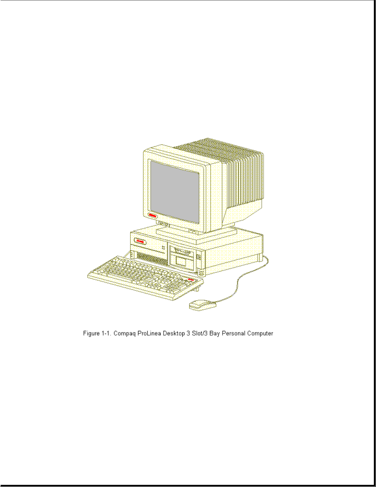
The Compaq ProLinea Family of Personal Computers introduces a new
generation of desktop computers designed for the business environment. The
family includes Desktop 3 slot/3 bay (DT3) and Desktop 4 slot/4 bay (DT4)
models. This chapter describes the model offerings and features of the DT3
and DT4 computers.
Page 5
Chapter 1.2 Models
The Compaq ProLinea Family of Personal Computers is available in the
desktop models described in the following sections.
Compaq ProLinea Personal Computer DT3 Models
The Compaq ProLinea Personal Computer is available in the DT3 models
described in Table 1-1. These desktop computers have two ISA expansion
slots, one shared PCI/ISA expansion slot, one Compaq option slot, and
three mass storage bays. All models include a 3.5-inch diskette drive.
Table 1-1. Compaq ProLinea Personal Computer DT3 Models *
===========================================================================
Model Processor Drive Memory Graphics Cache CD-ROM
===========================================================================
ProLinea 450 486DX2/50 None 8 MB PCI Local No
ProLinea 450 486DX2/50 270 MB 8 MB PCI Local No
ProLinea 450 486DX2/50 270 MB 4 MB PCI Local No
Hard
Bus
Bus
Bus
Page 6

ProLinea 466 486DX2/66 None 8 MB PCI Local No
Bus
ProLinea 466 486DX2/66 270 MB 8 MB PCI Local No
Bus
ProLinea 466 486DX2/66 420 MB 8 MB PCI Local No
Bus
ProLinea 4100 486DX4/100 None 8 MB PCI Local 128 KB No
Bus
ProLinea 4100 486DX4/100 270 MB 8 MB PCI Local 128 KB No
Bus
ProLinea 4100 486DX4/100 420 MB 8 MB PCI Local 128 KB No
Bus
ProLinea 575 586/75 None 8 MB PCI Local 256 KB No
Bus
ProLinea 575 586/75 270 MB 8 MB PCI Local 256 KB No
Bus
ProLinea 575 586/75 420 MB 8 MB PCI Local 256 KB No
Bus
--------------------------------------------------------------------------* Not all models are available in all geographic regions.
===========================================================================
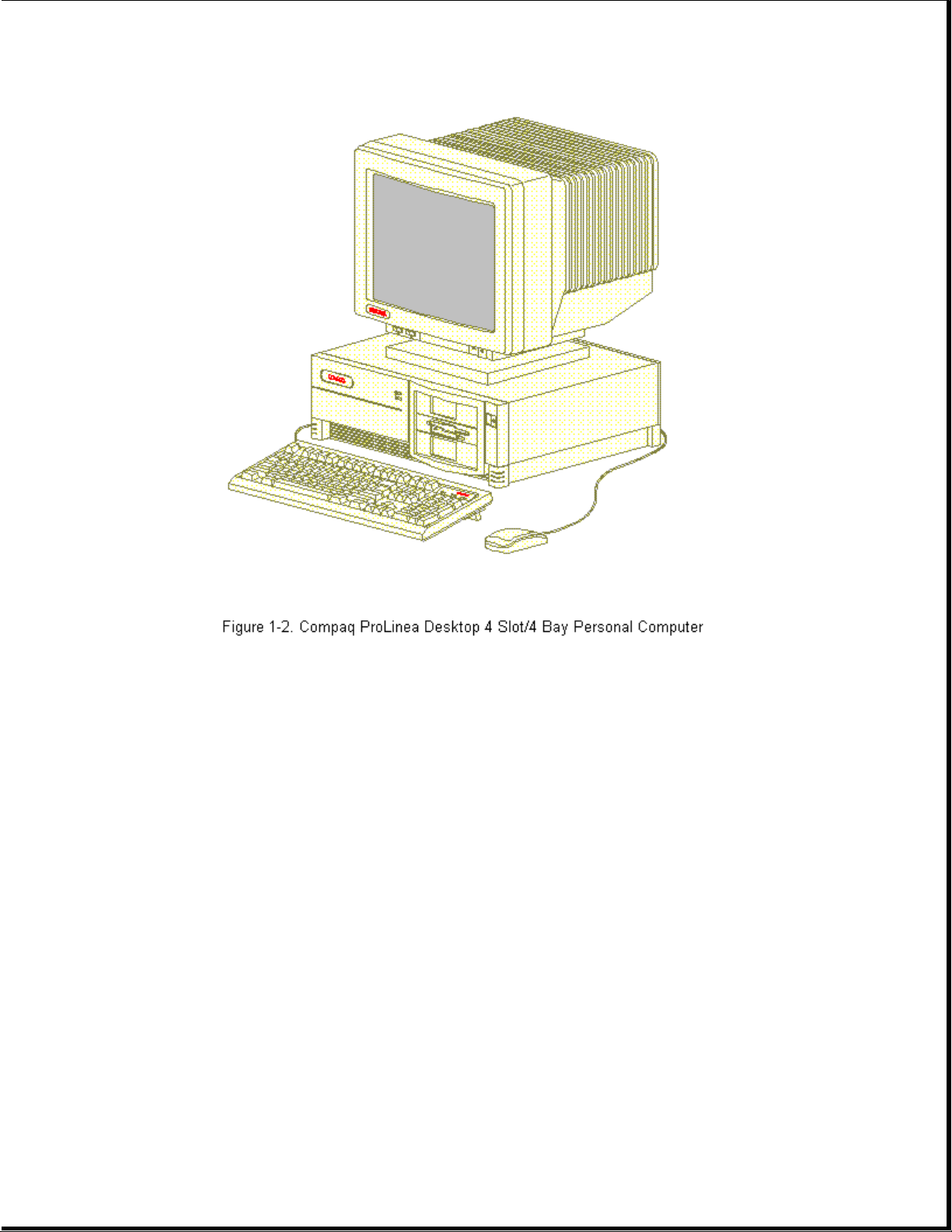
Compaq ProLinea Personal Computer DT4
Models
The Compaq ProLinea Personal Computer is available in the DT4 models
described in Table 1-2. These desktop computers have two ISA expansion
slots, two shared PCI/ISA expansion slots, one Compaq option slot, and
four mass storage bays. All models include a 3.5-inch diskette drive.
Table 1-2. Compaq ProLinea Personal Computer DT4 Models *
===========================================================================
Hard
Model Processor Drive Memory Graphics Cache CD-ROM
===========================================================================
ProLinea 450 486DX2/50 None 8 MB PCI Local No
Bus
ProLinea 450 486DX2/50 270 MB 8 MB PCI Local No
Bus
ProLinea 466 486DX2/66 None 8 MB PCI Local No
Bus
ProLinea 466 486DX2/66 270 MB 8 MB PCI Local No
Bus
ProLinea 466 486DX2/66 420 MB 8 MB PCI Local No
Page 7

Bus
ProLinea 466 486DX2/66 420 MB 8 MB PCI Local Yes
Bus
ProLinea 4100 486DX4/100 None 8 MB PCI Local 128 KB No
Bus
ProLinea 4100 486DX4/100 420 MB 8 MB PCI Local 128 KB No
Bus
ProLinea 4100 486DX4/100 420 MB 8 MB PCI Local 128 KB Yes
Bus
ProLinea 575 586/75 None 8 MB PCI Local 256 KB No
Bus
ProLinea 575 586/75 420 MB 8 MB PCI Local 256 KB No
Bus
ProLinea 575 586/75 420 MB 8 MB PCI Local 256 KB No
Bus
ProLinea 575 586/75 720 MB 16 MB QVision 256 KB No
2000+
ProLinea 575 586/75 720 MB 16 MB PCI Local 256 KB No
Bus
ProLinea 590 586/90 None 8 MB PCI Local 256 KB No
Bus
ProLinea 590 586/90 420 MB 8 MB PCI Local 256 KB No
Bus
ProLinea 590 586/90 420 MB 8 MB PCI Local 256 KB Yes
Bus
ProLinea 590 586/90 720 MB 16 MB QVision 256 KB No
2000+
ProLinea 590 586/90 720 MB 16 MB PCI Local 256 KB No
Bus
--------------------------------------------------------------------------* Not all models are available in all geographic regions.
===========================================================================
Chapter 1.3 Standard Features
The Compaq ProLinea Desktop Personal Computers have the following standard
features:
o 486DX2/50, 486DX2/66, 486DX4/100, 586/75, and 586/90 processors
o 4 MB (SIMM), 8 MB (soldered down) or 16 MB (soldered down) memory,
depending on model (see Table 1-4 for memory upgrade schedule)
Page 8

o 128 KB write back cache on 486DX4/100 models, 256 KB write back cache on
586/75 and 586/90 models
o 270, 420, or 720 MB IDE IntelliSafe hard drive (models available
without hard drive)
o Enhanced PCI local bus graphics:
- PCI Local Bus Integrated Graphics Controller on selected 486 and 586
models
- QVision 2000+ Graphics Controller on selected 586 models
o DT3 form factor includes: one PCI/ISA shared slot, two ISA slots, Compaq
option slot, one internal third-height drive bay, and two external
half-height drive bays
o DT4 form factor includes: two PCI/ISA shared slots, two ISA slots,
Compaq option slot, one internal third-height drive bay, one external
third-height drive bay, and two external half-height drive bays
o CD-ROM drive with Enhanced Business Audio on selected models
o PCI local bus IDE interface for hard drive and CD-ROM (up to 4 drives)
o Power conservation features
o Plug and play design
o One mouse port (PS/2 style Compaq mouse)
o Preloaded software
o Diagnostics/Setup software
o Security management
o Three-year limited warranty
Preloaded Software
The following software is preloaded on the Compaq ProLinea Desktop
Personal Computers:
o Microsoft Windows 3.1
o Diagnostics for Windows
o MS-DOS 6
o Windows Sound System 2.0 (CDS models only)
o ESS 688 Audio Drivers (CDS models only)
o Compaq Welcome Center, Compaq Control Center, and Compaq Learning Center
o Drivers for graphics and IDE CD-ROM
o Power Management
Page 9

o Security Management (see Section 1.6)
o Online documentation
Security Management
The following security management features are designed into the Compaq
ProLinea Desktop Personal Computers. These features can help prevent
unauthorized access to critical data and theft of the computer.
o Cable lock provision allows the user to physically secure the computer
hardware to protect against theft.
o Diskette boot control prevents the computer from being booted from a
diskette.
o Diskette drive control allows disabling of the diskette drive.
o Diskette write control prevents unauthorized writing of data to a
diskette.
o Hard drive control allows disabling of the hard drive.
o Flash ROM lock prevents unauthorized changes to the flash ROM.
o Keyboard password allows the computer to boot up but prevents data input
until the password is entered.
o Parallel interface control prevents transfer of data through the
parallel interface connector.
o Power-on password prevents unauthorized persons from booting up the
computer.
o QuickLock/QuickBlank allows the user to lock the keyboard and/or blank
the screen.
o Serial interface control prevents transfer of data through the serial
interface connector.
o Setup password prevents unauthorized changes to the system configuration.
Chapter 1.4 Options
The options that are available from Compaq for the Compaq ProLinea Family
of Personal Computers are described in the following sections.
Processor Upgrade
The processors in Compaq ProLinea Family of Personal Computers can be
upgraded according to the schedule in Table 1-3. Upgrade kits are
available from Compaq.
Table 1-3. Processor Upgrades
===========================================================================
Page 10

Base processor Can be upgraded to
===========================================================================
486DX2/50 486DX2/66, or 486DX4/100
486DX2/66 486DX4/100
586/75 586/90
===========================================================================
System Memory Options
The system memory options that are available from Compaq for the Compaq
ProLinea Family of Personal Computers are listed below. The memory modules
are SIMM, 70ns, without parity.
o 4 MB memory module
o 8 MB memory module
o 16 MB memory module
o 32 MB memory module
System memory can be upgraded according to the schedule in Table 1-4:
Table 1-4. Upgrade Schedule
===========================================================================
Processor Standard Memory Expandable to SIMM Sockets
===========================================================================
486DX2/50 4 MB 128 MB 4
486DX2/50 8 MB 136 MB 4
486DX2/66 8 MB 136 MB 4
486DX4/100 8 MB 136 MB 4
586/75 8 MB 192 MB 6
586/75 16 MB 192 MB 6
586/90 8 MB 192 MB 6
586/90 16 MB 192 MB 6
===========================================================================
Secondary Cache
Secondary cache memory option cards (128 KB or 256 KB) are available for
the 486DX2/50, 486DX2/66, and 486DX4/100 models of the Compaq ProLinea
Family of Personal Computers.
NOTE: All 586-class models have 256 KB secondary cache soldered to the
system board.
Page 11

Mass Storage Options
The following mass storage options are available from Compaq for the
Compaq ProLinea Family of Personal Computers:
o 1.2 MB diskette drive, 5.25-inch, half-height
o 1.44 MB diskette drive, 3.5-inch, third-height
o 270 MB IDE hard drive
o 420 MB IDE hard drive
o 540 MB IDE hard drive
o 720 MB IDE hard drive
o 1 GB IDE hard drive
o 535 MB SCSI-2 hard drive
o 1.05 GB SCSI-2 hard drive
o 2.1 GB SCSI-2 hard drive
o 120/250 MB tape drive with compression
o 340/680 MB tape drive
o 525 MB tape drive
o 1.2 GB ACA tape drive
o 2/8 GB Turbo DAT tape drive
o Internal Quad-Speed IDE CD-ROM drive
Monitor Options
The following monitor options are available from Compaq for the Compaq
ProLinea Family of Desktop Personal Computers:
o QVision 200 Color Monitor with AssetControl
o QVision 172 Color Monitor with AssetControl
o VGA 14-Inch Monochrome Monitor
o SVGA Color Monitor with low emissions and energy saver
o VGA Color Monitor with low emissions
o Compaq 14-Inch 1024 Color Monitor
o Compaq 151 FS Color Monitor with low emissions and AssetControl
Page 12

o Compaq 171 FS Color Monitor with low emissions and AssetControl
NOTE: The Compaq ProLinea Family of Personal Computers does not support
the AssetControl feature.
Graphics Controllers and Memory Options
The following graphics controller and memory options are available from
Compaq for the Compaq ProLinea Family of Personal Computers:
o QVision 2000+ Graphics Controller with 2 MB VRAM
o QVision 1280/I Graphics Controller with 2 MB VRAM
o QVision 1280/P+ Graphics Controller with 1 MB VRAM (has VAFC connector)
o 1 MB DRAM graphics memory module for PCI Local Bus Integrated Graphics
Controller
o 1 MB VRAM graphics memory module for QVision 1280/P+ Graphics Controller
o 2 MB VRAM graphics memory module for QVision 2000+ Graphics Controller
Serial/Parallel Interface Board
Ther serial/parallel board option is available from Compaq for the
ProLinea Family of Personal Computers. This board uses an expansion slot
and provides additional serial and parallel device support to the computer.
Modem
The SpeedPaq 144/I internal fax/modem is available from Compaq for the
Compaq ProLinea Family of Personal Computer:
Software Options
The following software options are available from Compaq for the Compaq
ProLinea Family of Personal Computer:
o MS-DOS 6 (3.5-inch diskettes)
o Corporate license agreements for MS-DOS 6
o MS-DOS 6 LicensePaq
o MS-DOS 6 corporate upgrade (100+ users)
o MS-DOS 6 LicensePaq upgrade
o SCO UNIX O/S from Compaq version 4.1 (with media kit)
o SCO UNIX network bundle from Compaq version 4.1 (with media kit)
o SCO UNIX and TCP/IP Development System from Compaq release 1.2
Page 13
o SCO XSight Runtime version 4.1
o Open Desktop Development System, release 3.0
o Windows NT
o Sytos Plus Tape software for MS-DOS
o Sytos Plus Tape software for OS/2
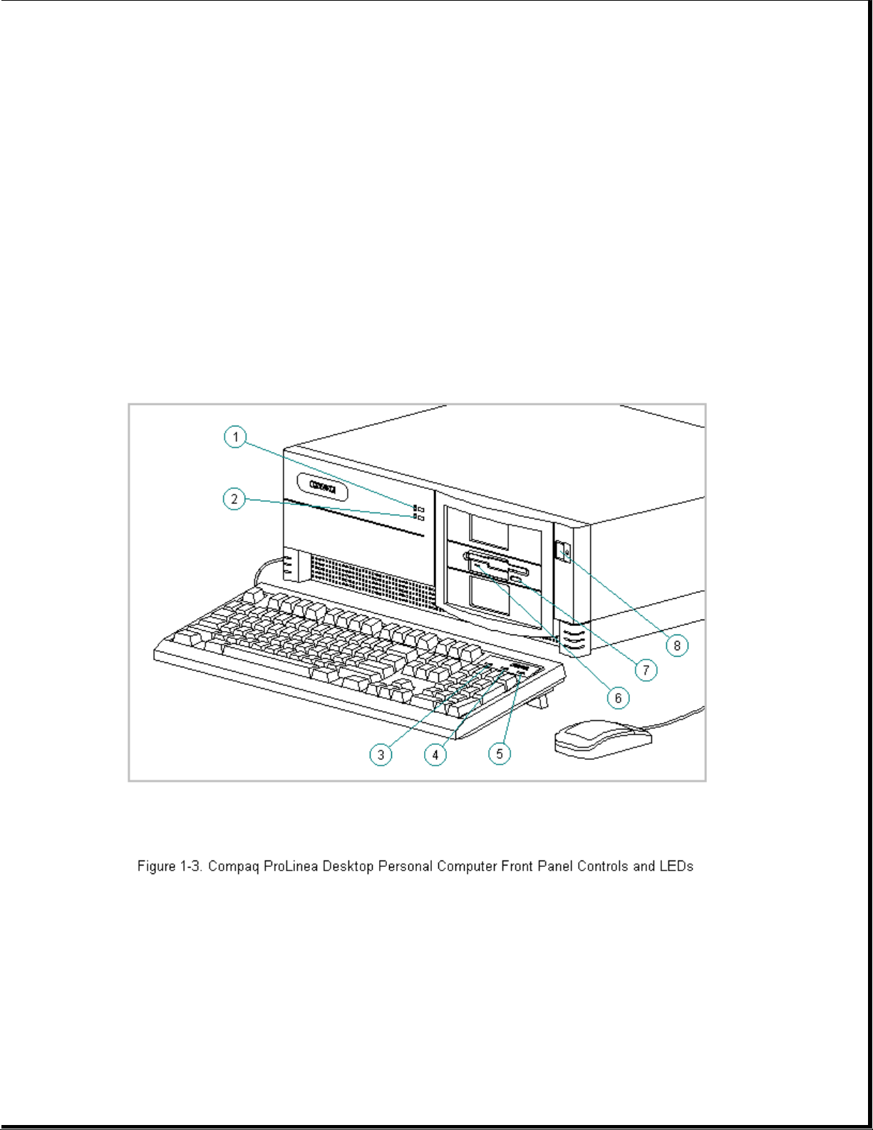
Chapter 1.5 Front Panel Controls and LEDs
The front panel controls and LEDs for the DT3 and DT4 are almost
identical. The controls and LEDs are identified in Figure 1-3 and
described in Table 1-5.
Table 1-5. Front Panel Controls and LEDs
===========================================================================
Item Description Function
===========================================================================
1 Power-On Light Turns on when the computer is turned on and
blinks (optional) in Energy Saver mode.
2 Hard Drive Activity Turns on when the hard drive is reading or
Page 14

Light writing.
3 Num Lock Light When the Num Lock light is on, the numeric
keypad is activated.
4 Caps Lock Light When the Caps Lock light is on, all letters
typed will be capitalized.
5 Scroll Lock Light When the Scroll Lock light is on, the
screen will not scroll.
6 Diskette Drive Turns on when the diskette drive is reading
Activity Light or writing.
7 Diskette Eject Button Ejects a loaded diskette.
8 Power (On/Off) Switch Turns the computer on and off.
===========================================================================
Chapter 1.6 Rear Panel Controls and Connectors
The controls and connectors located on the rear of the DT3 and DT4 are
almost identical. They are identified in Figure 1-4 and described in
Table 1-6. See Appendix A for connector pin assignments.
Page 15
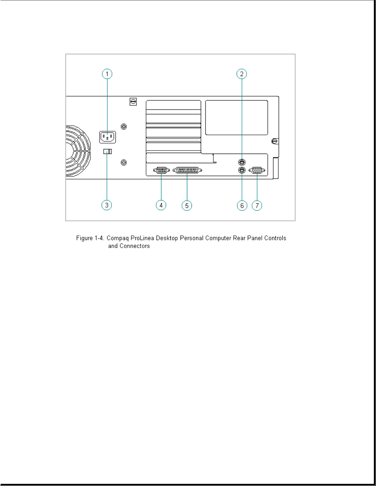
Table 1-6. Rear Panel Controls and Connectors *
===========================================================================
Item Description Function
===========================================================================
1 Power Cord Connector Connects the computer to an electrical power
outlet.
2 Mouse Connector Connects the mouse.
3 Voltage Select Switch Switches voltage between 115 VAC (US) and
230 VAC to match geographical requirements.
4 Serial Port Connects to serial devices, such as a serial
printer.
5 Parallel Port Connects to parallel devices, such as a
parallel printer.
6 Keyboard Connector Connects the keyboard.
7 Monitor Connector Connects the monitor.
--------------------------------------------------------------------------* Actual connectors will vary with models.
===========================================================================
Page 16

Chapter 1.7 System Design
This section presents a design overview and functional descriptions of the
key components of the Compaq ProLinea Family of Personal Computers. All
replaceable components are identified in Chapter 3 and removal/replacement
instructions are presented in Chapter 5.
Design Overview
The Compaq ProLinea Family of Personal Computers has a conventional design
that uses a pan-type chassis to house the system board, expansion cards,
power supply, and mass storage devices. The chassis is divided into two
sections by a permanent panel that extends from the front to the rear of
the chassis. This panel provides a mounting surface for the backplane
board and separates the system board section from the section that houses
the power supply and mass storage devices.
All internal components are immediately accessible when the unit cover,
held in place by three thumb screws, is removed. The front bezel is
mounted to the unit cover. Torx T-15 screws are used throughout the system
except for the CD-ROM drive bracket which requires Torx T-10 screws.
The system board is easily removed by sliding it out from the side of the
chassis after the unit cover is removed. The system board bracket,
attached to the system board with three Torx screws, forms the right side
of the chassis when the system board is installed. The system board shares
the common backplane board with the expansion cards. No mounting screws
are used with the system board.
Expansion boards are installed horizontally above the system board,
engaging the backplane board which is attached to the central panel. A
single screw attaches the expansion board to the rear panel of the
chassis.
The power supply is mounted in the right rear corner of the chassis.
Integrated clips on the bottom of the power supply engage cutouts in the
floor of the chassis. The power supply is held in place by four Torx
screws that are installed through the rear panel of the chassis.
The mass storage drive cage is located on the right side of the chassis,
directly in front of the power supply. The drive cage can be tilted up
from the rear to provide access to cable connections. The drive cage can
accommodate one internal hard drive attached to the side of the cage and
provides two or three (model dependent) drive bays for accessible mass
storage devices.
Detailed descriptions of the system components are presented in the
sections that follow.
System Board
The Compaq ProLinea Family of Personal Computers uses four basic system
board configurations. All of the boards use SIMMs for expanded memory;
four SIMM sockets on 486 models and six SIMM sockets on 586 models. The
486 models have 8 MB RAM soldered down on the system board; one of the 486
models has 4 MB RAM soldered down. The 586 models have either 8 MB or
16 MB SIMMs for RAM. The configurations are described in the following
sections.
Page 17

486-Based Board With 4 MB RAM
The 486-based system board with 4 MB RAM has the following characteristics:
o Used on 3-slot/3-bay and 4-slot/4-bay computers
o 4 MB SIMMs
o 4 SIMM sockets for memory expansion
o PCI Local Bus integrated graphics controller
o Accommodates 486DX2/50, 486DX2/66, and 486DX4/100 processors (238-pin
ZIF socket)
o 128 KB cache memory standard on 486DX4/100 models only; 128 KB and
256 KB options for 486DX2 models
o Measures 8.5 x 11.5 inches (21.6 x 29.2 cm)
486-Based Board With 8 MB RAM
The 486-based system board with 8 MB RAM has the following
characteristics:
o Used on 3-slot/3-bay and 4-slot/4-bay computers
o Integrated 8 MB RAM on the system board
o 4 SIMM sockets for memory expansion
o PCI Local Bus integrated graphics controller
o Accommodates 486DX2/50, 486DX2/66, and 486DX4/100 processors (238-pin
ZIF socket)
o 128 KB cache memory standard on 486DX4/100 models only; 128 KB and
256 KB options for 486DX2 models
o Measures 8.5 x 11.5 inches (21.6 x 29.2 cm)
586-Based Board With DRAM Graphics
The 586-based system board with integrated DRAM graphics has the following
characteristics:
o Used on 3-slot/3-bay and 4-slot/4-bay computers
o PCI Local Bus integrated graphics controller
o Six SIMM sockets for memory expansion
o Accommodates 586/75 and 586/90 processors (320-pin ZIF socket)
o 256 KB cache memory
Page 18

o Measures 8.5 x 13.75 inches (21.6 x 34.9 cm)
586-Based Board Without Integrated Graphics
The 586-based system board without integrated graphics has the following
characteristics:
o Used on 3-slot/3-bay and 4-slot/4-bay computers
o Designed for use with QVision 2000+ Graphics Controller in a PCI slot
o Six SIMM sockets for memory expansion
o Accommodates 586/75 and 586/90 processors (320-pin ZIF socket)
o 256 KB cache memory
o Measures 8.5 x 13.75 inches (21.6 x 34.9 cm)
IDE Interface
The IDE interface consists of two IDE connectors that support up to four
IDE devices. Each connector can be individually disabled so that option
card IDE interfaces will work.
Diskette Drive Interface
The diskette drive interface is 8477 compatible.
Serial Port
The serial port is RS-232C compatible.
Parallel Port
The following parallel support modes are supported:
o SPP (Bi-directional Standard Parallel Port)
o EPP (Enhanced Parallel Port)
o ECP (Extended Capabilities Port)
Keyboard/Mouse
All system boards will accommodate a standard 8042 keyboard/mouse
controller.
Processor
The 486-based system boards support a variety of 486 processors at bus
frequencies of 25-MHz and 33-MHz. These boards have a reconfigurable ZIF
socket to accommodate the variety of processor pinouts and supports 3.3V
and 5V processors. These system boards can be upgraded to a 486DX4/100
Page 19

processor.
The 586-based system boards support the 586 processor running at bus
frequencies of 50-MHz and 60-MHz.
Memory
All of the computers use 70ns enhanced page-mode DRAMs. Memory parity is
not supported.
The 486-based system boards accommodate a total of four double-sided
SIMMs. Either a single-sided 4 MB SIMM or 8 MB of soldered down DRAMs is
installed for base memory.
The 586-based system boards accommodate a total of six double-sided SIMMs.
Either two single-sided 4 MB SIMMs or two double-side 8 MB SIMMs are
installed for base memory.
Memory Expansion
The SIMM sockets on the 486-based system board can be populated with 4,
8, 16, or 32 MB SIMMs in any order. The SIMM sockets on the 586-based
system boards must be populated in pairs of equal size in sequential
slots. The SIMMs must be 70ns or faster.
IMPORTANT: SIMMS with tin-lead pins must be used for memory upgrades.
Cache
All of the computers support a second level write-back cache. 486DX2/XX
and 486DX4/100 models support an optional 128 KB or 256 KB cache board.
586 models support an integrated 256 KB cache.
Graphics
The Compaq ProLinea Family of Personal Computers is supported with a
2-tiered graphics strategy.
The 486-based system boards and selected 586-based system boards are
shipped with a PCI Local Bus integrated graphics controller. These system
boards are provided with 1 MB DRAM. Additional memory is provided with a
daughter card. The PCI Local Bus integrated graphics controller supports
the following maximum screen resolutions:
o 1024 x 768 x 256 colors with 1 MB DRAM
o 1280 x 1024 x 256 colors with 2 MB DRAM
Selected 586-based system boards are designed to be used with a QVision
2000+ Graphics Controller in a PCI slot. This will provide the following
maximum screen resolutions:
o 1280 x 1024 x 256 colors with 2 MB VRAM
o 1280 x 1024 x 16.7M colors with 4 MB VRAM
Page 20

Chapter 2. Troubleshooting
Chapter 2.0 Introduction
This chapter describes the three levels of troubleshooting for the
computer:
o Power-On Self-Test (POST)
o Compaq diagnostics
o Troubleshooting without diagnostics
POST messages, diagnostic error codes, and memory error codes are
included. The messages and codes appear in tables that include a
description of the error, the probable cause, and the recommended action
to resolve the error condition. Adherence to the procedures and
precautions described in this chapter is essential for proper service.
Chapter 2.1 Power-On Password
The power-on password prevents use of the computer until the password is
entered. To clear the power-on password, you must remove and replace a
jumper on the system board. If you do not know the power-on password, use
the following procedure to clear the password to allow troubleshooting:
1. Complete the preparation for disassembly procedures in Section 5.3.
2. Remove the unit cover as described in Section 5.4.
3. Move the jumper on E6 (Figure 2-1) from pins 1 and 2 and to pins 2
and 3.
Page 21
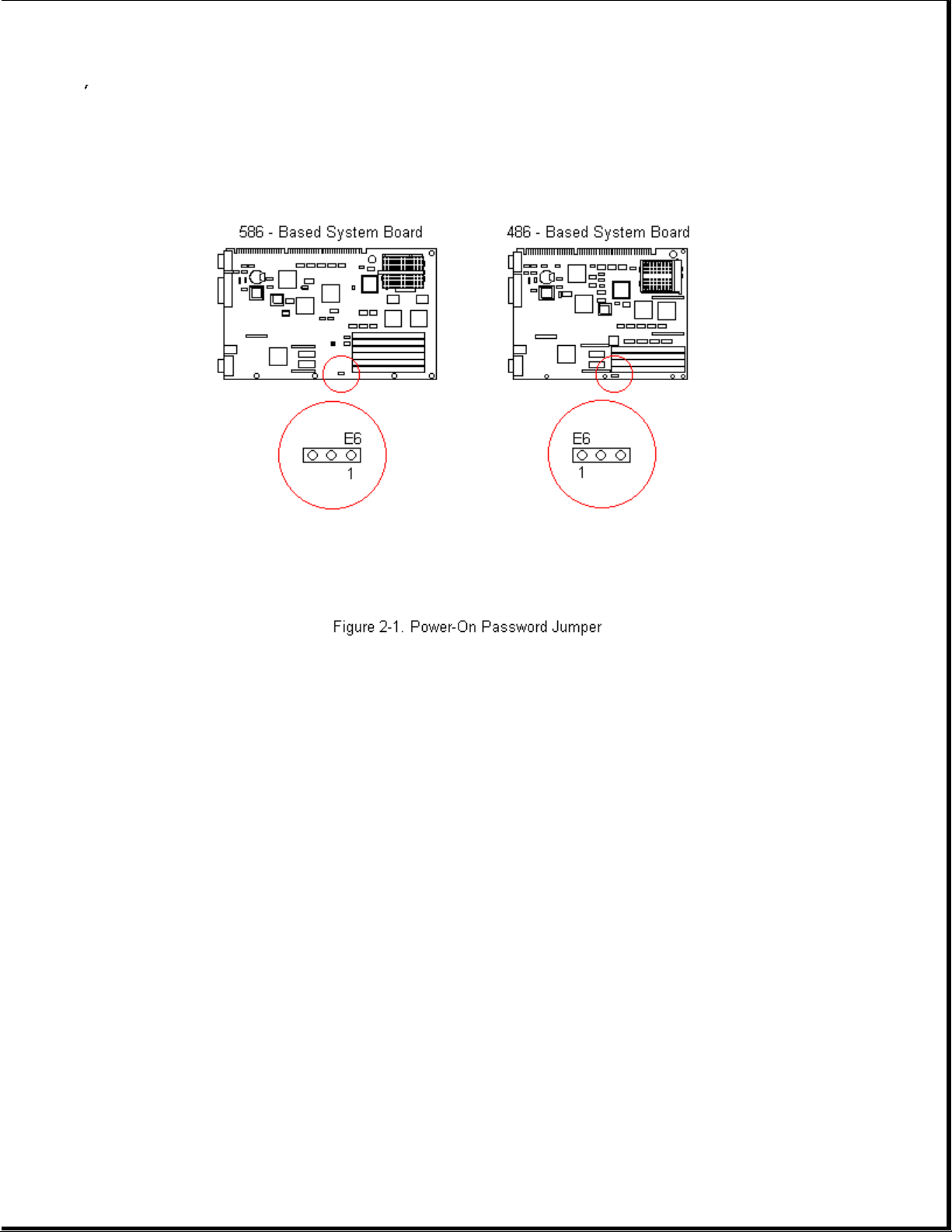
4. Replace the unit cover and perform the desired troubleshooting.
Chapter 2.2 Power-On Self-Test
Power-on Self-Test (POST) is a series of diagnostic tests that runs
automatically when the system is turned on. POST checks the following
assemblies to ensure that the computer system is functioning properly:
o Keyboard
o Power supply
o System board
o System memory
o Memory modules
o Controllers
o Graphics system
o Diskette drives
Page 22

o Hard drives
POST also detects the type of mass storage devices installed in the
computer. If POST finds an error in the system, an error condition is
indicated by an audible and/or visual message.
Power-on Self-Test Messages
An error message results if a problem is encountered during the Power-On
Self-Test utility. Table 2-1 lists the messages for POST, the audible
(beep) message, probable cause, and recommended action. The procedures
referenced under "Recommended Action" are described in Sections 2.3 and
2.4 of this chapter.
Table 2-1. Power-On Self-Test Messages
===========================================================================
Message Beeps Probable Cause Recommended Action
===========================================================================
101 - ROM Error 1 Long, System ROM checksum 1. Inspect the ROM
1 Short placement.
2. Verify the
correct ROM.
3. Replace the ROM.
--------------------------------------------------------------------------101 - I/0 ROM None Option ROM checksum 1. Inspect the ROM
Error placement.
2. Verify the
correct ROM.
3. Replace the ROM.
--------------------------------------------------------------------------102 - System None DMA, timers, etc. Replace the system
Board Failure board.
--------------------------------------------------------------------------162 - System 2 Short No diskette drive or Run Computer Setup.
Options Error mismatch in drive
type
--------------------------------------------------------------------------162 - System 2 Short Configuration Run Computer Setup.
Options Not incorrect
Set
--------------------------------------------------------------------------163 - Time & 2 Short Invalid time or date Run Computer Setup.
Date Not Set in configuration
memory
--------------------------------------------------------------------------164 - Memory 2 Short Configuration Run Computer Setup.
Size Error memory incorrect
--------------------------------------------------------------------------174 - ISA 1 Short Plug & Play ISA Run the
Configuration/ board not found Configuration and
Slot Mismatch Diagnostics
Utilities.
--------------------------------------------------------------------------175 - ISA 1 Short Plug & Play ISA Run the
Configuration/ board added, Configuration
Slot Mismatch configuration not and Diagnostics
updated Utilities.
Page 23

--------------------------------------------------------------------------178 - Processor None Processor type or Run Computer Setup.
Configuration step do not match
Invalid configuration
memory
--------------------------------------------------------------------------201 - Memory None RAM failure 1. Run Computer
Error Setup.
2. Replace the
memory module(s)
(if any).
3. Replace system
board.
--------------------------------------------------------------------------203 - Memory None RAM failure 1. Run Computer
Address Error Setup.
2. Replace the
memory module(s)
(if any).
3. Replace system
board.
--------------------------------------------------------------------------Message Beeps Probable Cause Recommended Action
---------------------------------------------------------------------------
205 - Memory Error None Cache memory error Run the
Configuration and
Diagnostics
Utilities.
--------------------------------------------------------------------------206 - Secondary None Cache memory Run the
cache controller controller or RAM Configuration
Failure failure and Diagnostics
Utilities.
--------------------------------------------------------------------------301 - Keyboard None Keyboard Failure Reconnect keyboard
Error with computer
turned off.
--------------------------------------------------------------------------301 - Keyboard None Keyboard Failure Replace the
Error or Text keyboard.
Fixture Installed
--------------------------------------------------------------------------303 - Keyboard None I/O board keyboard Replace the system
Controller Error controller board.
--------------------------------------------------------------------------304 - Keyboard or None Keyboard 1. Replace the
System Unit Error keyboard.
2. Replace the
system board.
--------------------------------------------------------------------------40X - Parallel 2 Short Both external and Run Computer Setup.
Port X Address internal ports are
Assignment assigned to parallel
Conflict port X
--------------------------------------------------------------------------402 - Monochrome 1 Long, Monochrome display Replace the
Adapter Failure 2 Short controller monochrome display
controller.
Page 24

--------------------------------------------------------------------------501 - Display 1 Long, Video display Replace the video
Adapter Failure 2 Short controller board.
--------------------------------------------------------------------------601 - Diskette None Diskette controller 1. Check and/or
Controller Error circuitry replace cables.
2. Replace the
system board.
--------------------------------------------------------------------------602 - Diskette None Diskette in drive A Replace the
Boot not bootable diskette.
--------------------------------------------------------------------------605 - Diskette 2 Short Mismatch in drive Run Computer Setup.
Drive Error type
--------------------------------------------------------------------------611 - Primary 2 Short Configuration error Run Computer Setup.
Floppy Port
Address Assignment
Conflict
--------------------------------------------------------------------------612 - Secondary 2 Short Configuration error Run Computer Setup.
Floppy Port
Address Assignment
Conflict
--------------------------------------------------------------------------702 - A None Configuration error Run Computer Setup.
Coprocessor Has
Been Detected That
Is Not Reported In
CMOS
--------------------------------------------------------------------------703 - CMOS Reports 2 Short Configuration error Run Computer Setup.
a Coprocessor That
Has Not Been
Detected By POST
--------------------------------------------------------------------------Message Beeps Probable Cause Recommended Action
---------------------------------------------------------------------------
1151 - COM Port 1 2 Short Both external and Run Computer Setup.
Address Assignment internal serial ports
Conflict are assigned to COM1
--------------------------------------------------------------------------1152 - COM Port 2 2 Short Both external and Run Computer Setup.
Address Assignment internal serial ports
Conflict are assigned to COM2
--------------------------------------------------------------------------1153 - COM Port 3 2 Short Both external and Run Computer Setup.
Address Assignment internal serial ports
Conflict are assigned to COM3
--------------------------------------------------------------------------1154 - COM Port 4 2 Short Both external and Run Computer Setup.
Address Assignment internal serial ports
Conflict are assigned to COM4
--------------------------------------------------------------------------1771 - Primary 2 Short Internal and external Run Computer Setup.
Disk Port Address hard drive
Assignment controllers are both
Conflict assigned to
Page 25

primary address
--------------------------------------------------------------------------1772 - Secondary 2 Short Internal and external Run Computer Setup.
Disk Port Address hard drive
Assignment controllers are both
Conflict assigned to the
secondary address
--------------------------------------------------------------------------1780 - Disk 0 None Hard drive/format Run the
Failure error Configuration and
Diagnostics
Utilities.
--------------------------------------------------------------------------1781 - Disk 1 None Hard drive/format Run the
Failure error Configuration and
Diagnostics
Utilities.
--------------------------------------------------------------------------1782 - Disk None Hard drive circuitry Run the
Controller error Configuration and
Diagnostics
Utilities.
--------------------------------------------------------------------------1790 - Disk 0 None Hard drive error or Run the
Failure wrong drive type Configuration and
Diagnostics
Utilities.
--------------------------------------------------------------------------1791 - Disk 1 None Hard drive error or Run the
Failure wrong drive type Configuration and
Diagnostics
Utilities.
--------------------------------------------------------------------------XX000Y ZZ Parity None Parity RAM failure Run the
Check 2 Configuration and
Diagnostics
Utilities.
--------------------------------------------------------------------------Hard Drive 3 Long Configuration or Run the
Parameter Table or hardware failure Configuration and
BIOS Error system Diagnostics
Halted Utilities.
--------------------------------------------------------------------------IOCHECK Active None Defective board in Run the
Slot X slot X Configuration and
Diagnostics
Utilities.
--------------------------------------------------------------------------Bus Master Timeout None Defective board in Run the
Slot X slot X Configuration and
Diagnostics
Utilities.
--------------------------------------------------------------------------Audible 1 Short Power-on successful None.
--------------------------------------------------------------------------Audible 2 Short Power-on successful None.
--------------------------------------------------------------------------(RESUME = F1 KEY) None As indicated Press the F1 key.
to continue
===========================================================================
Page 26

Chapter 2.3 Compaq Diagnostics
This section explains how to use the Configuration and Diagnostics
utilities installed on the computer.
IMPORTANT: If you are planning to run an alternate operating system (e.g.,
OS/2 or UNIX), you will need to configure your system using the
Compaq Diagnostics diskette. Failure to do so can result in
loss of data and reduced hard drive capacity.
Both Windows and DOS have configuration and diagnostic utilities that
should be accessed in the following instances:
o When a system configuration error is detected during the Power-On
Self-Test (POST).
o To change factory default settings for some of the computer features.
o To change the system configuration, which is sometimes necessary when
you add or remove optional hardware.
o To set system configuration features.
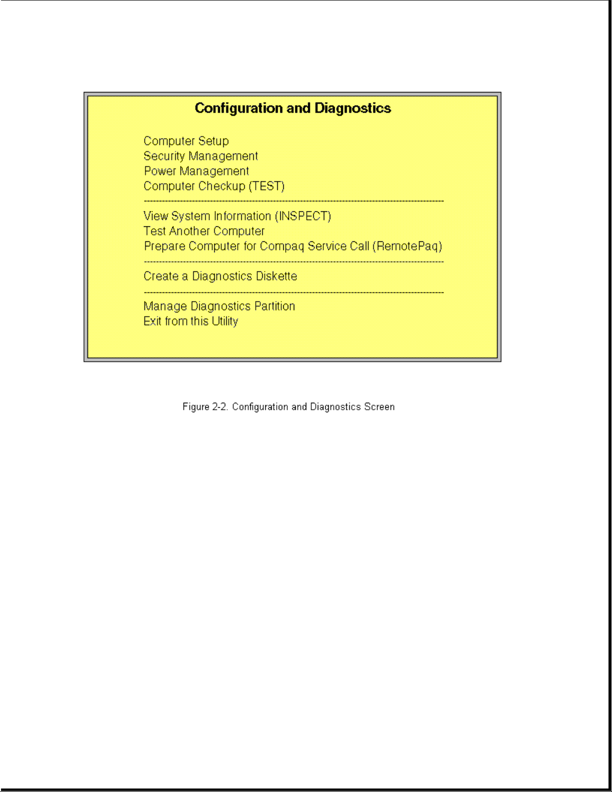
The same utilities are available by selecting options on a menu called
"Configuration and Diagnostics." To display this menu, restart the
computer, then press the F10 key when the square cursor displays in the
upper-right corner of the screen. Full instructions are presented later in
this section. Diagnostics are available by selecting the Computer Checkup
(TEST) utility on the Configuration and Diagnostics menu.
Compaq Diagnostics are installed on the hard drive of the Compaq ProLinea
Personal Computer. The diagnostics are also available on diskettes.
IMPORTANT: The diagnostics and setup utilities are located on a hard disk
partition in the computer, not on ROM. Details for recreating
the diagnostics/setup partition are presented in Section 2.4 of
this chapter.
You can access the diagnostics at startup from the hard drive or from the
diskettes. Procedures for both methods are presented below. Both
procedures will result in the Configuration and Diagnostics menu being
displayed. Your particular menu may differ slightly from the one shown in
Figure 2-2.
Page 27
Accessing the Configuration and Diagnostics Menu at Startup
To display the menu immediately after startup, complete the following
steps:
1. Turn on or restart the computer (Ctrl+Alt+Delete).
2. Press the F10 key as soon as the cursor moves to the upper-right corner
of the screen. This occurs immediately: The Power-On Self-Test (POST)
runs, you hear two beeps, then the cursor moves to the upper-right
corner.
3. If prompted, select the desired language.
4. A menu similar to the one shown in Figure 2-2 will be displayed. You
will be prompted through any procedure that you select.
Accessing the Configuration and Diagnostics Menu from Diskette
You can load either the Setup or Diagnostics diskette with this procedure.
To load either of the diskettes, complete the following steps:
1. Insert the diskette into drive A.
Page 28

2. Turn on or restart the computer (Ctrl+Alt+Delete).
3. If prompted, select the desired language.
4. If you load the Diagnostics diskette, a menu similar to the one shown
in Figure 2-2 will be displayed. If you select Computer Setup from this
menu, you will be prompted to insert the Setup diskette. You will be
prompted through any procedure that you select.
Compaq Diagnostics for Windows
Compaq Diagnostics for Windows utility contains the same functionality as
the DOS-based INSPECT program but in a Windows environment. To use the
Compaq Diagnostics for Windows utility, select the Compaq Diagnostics icon
from the Compaq Utilities group box. Once the program is running, you can
use the tool bar or the menus to browse through the information. Some
examples of the information you can view are:
o Product name
o CPU information
o Cache size and type
o Mouse driver versions
o COM ports, LPT ports, modems
o ISA and PCI slot information
o Version of certain software (MS-DOS, Windows)
o ROM version
o Storage information
o Power Management settings
o Multimedia devices information
The MS-DOS version of INSPECT is available on the system partition and is
accessible as explained earlier in this section.
Chapter 2.4 Configuration and Diagnostics Menu Options
The Configuration and Diagnostics menu contains the following
troubleshooting utilities:
o Computer Setup
o Computer Checkup (TEST)
o View System Information (INSPECT)
o Test another computer
Page 29

o Prepare computer for Compaq Service Call (RemotePaq)
o Create a Diagnostics Diskette
See the user documentation for descriptions of the Security Management and
Power Management utilities. A brief description of each of the
troubleshooting utilities is presented below. Ample prompting is provided
with each of these utilities.
Computer Setup
The Computer Setup utility is preinstalled on the hard drive and on
diskette. It gives a snapshot of the computer's hardware configuration,
aids in troubleshooting, and allows you to set custom features. Computer
Setup recognizes a newly installed internal or external device and
automatically updates the Computer Setup screen. Among the parameters
checked are the following:
o Date and time
o Installed devices
o Memory status
o Password status
o Interface configurations
o Graphics configuration
o Computer serial number
o Controller status
The following activities can be performed from this screen:
o Press the Esc key to exit the screen and return to the startup
procedure.
o Press the F1 key for instructions on how to navigate around the screen.
Computer Checkup (TEST)
Computer Checkup (TEST) is a utility that confirms if the various computer
devices are recognized by the system and functioning properly. Use the
TEST utility to help set up and test the computer and to install the
operating system. The TEST menu offers the following:
o Quick Check Diagnostics runs a quick, general test on each device with a
minimal number of prompts. If errors occur, they are displayed when the
test is complete.
o Automatic Diagnostics runs unattended and provides maximum testing of
Page 30

each device with minimal prompts. You can choose how many times to run
the tests, to stop on errors, or to print or file a log of errors.
o Prompted Diagnostics allows maximum control over the device testing
process. You can choose attended or unattended testing, decide to stop
on errors, or choose to print or file a log of errors.
The TEST option checks the following:
o CPU (main system)
o Keyboard
o Pointing device interface
o Parallel interfaces
o Graphics controllers
o Diskette drives
o Fixed disks
o Serial interfaces
o Installed Compaq devices (tape drive, SCSI device, or network status)
View System Information (INSPECT)
This utility allows you to inspect the status and configuration of the
following parameters:
o System
o System ROM
o Keyboard
o System ports
o System storage
o Graphics
o Memory
o Operating system
o System files
o Windows files
o Network status
o Miscellaneous
Page 31

The options available from this utility are:
o Print the inspect status.
o Save the inspect status to a file.
o Add comments to a parameter status.
o Exit the utility.
Test Another Computer
This utility allows you to download Computer Checkup (TEST), View System
Information (INSPECT), or Computer Setup utilities through your computer's
serial interface to a supported Compaq product that does not have a
diskette drive.
RemotePaq
This utility is available in some geographical areas and requires a modem.
The utility prepares your computer for a call from Compaq Service via
modem. It allows Compaq Customer Support to automatically run diagnostics
on your machine.
Create a Diagnostics Diskette
This option allows you to back up the diagnostics software onto two
diskettes.
IMPORTANT: Compaq highly recommends that backup diagnostics diskettes are
created as soon as the system is configured. This software is
required to troubleshoot the system if the hard drive cannot be
accessed or must be replaced.
Manage Diagnostics Partition
This option allows you to create, delete, or upgrade the diagnostics
software on your computer. If the diagnostics partition is deleted, it can
be recreated without deleting the DOS partition. The most likely use of
this option is to upgrade the utilities.
Chapter 2.5 Diagnostic Error Codes
Diagnostic error codes occur if the system recognizes a problem while
running the Compaq Diagnostic program. These error codes help identify
possibly defective subassemblies.
Tables 2-2 through 2-15 list possible error codes, a description of the
error condition, and the action required to resolve the error condition.
IMPORTANT: Retest the system after completing each step. If the problem
has been resolved, do not proceed with the remaining steps.
Page 32

For assistance in the removal and replacement of a particular subassembly,
see Chapter 5, "Removal and Replacement Procedures."
Table 2-2. Processor Test Error Codes
===========================================================================
Error
Code Description Recommended Action
===========================================================================
101 - xx CPU test failed Replace the system board and retest.
---------------------------------------------------------------------------
102 - xx Coprocessor or Weitek 1. Run the Configuration and
Error Diagnostics Utilities.
2. Replace the coprocessor and retest.
3. Replace the processor
(if applicable) and retest.
--------------------------------------------------------------------------103 - xx DMA page registers Replace the system board and retest.
test failed
104 - xx Interrupt controller
master test failed
105 - xx Port 61 error
106 - xx Keyboard controller
self-test failed
--------------------------------------------------------------------------107 - xx CMOS RAM test failed The following steps apply to 107 - xx
through 109 - xx:
108 - xx CMOS interrupt test
failed 1. Replace the battery/clock module and
retest.
109 - xx CMOS clock test 2. Replace the system board and retest.
failed
--------------------------------------------------------------------------110 - xx Programmable timer Replace the system board and retest.
load data test failed
113 - xx Protected mode test
failed
--------------------------------------------------------------------------114 - 01 Speaker test failed 1. Check system configuration.
2. Verify cable connections to speaker.
3. Replace the system board and retest.
===========================================================================
Table 2-3. Memory Test Error Codes
===========================================================================
Error
Code Description Recommended Action
===========================================================================
200 - xx Memory machine ID The following steps apply to 200 - xx and
test failed 202 - xx:
202 - xx Memory system ROM 1. Replace the system ROM and retest.
checksum failed 2. Replace the system board and retest.
--------------------------------------------------------------------------203 - xx Write/Read test The following steps apply to 203 - xx
Page 33

failed through 215 - xx:
204 - xx Address test failed 1. Remove the memory modules one at a
time until the error goes away.
211 - xx Random pattern test 2. Replace the good modules one at a
failed time while making sure the error code
does not return.
214 - xx Noise test failed 3. Replace the bad modules and retest.
215 - xx Random address test
failed
===========================================================================
Table 2-4. Keyboard Test Error Codes
===========================================================================
Error
Code Description Recommended Action
===========================================================================
300 - xx Failed ID Test The following steps apply to 300 - xx
through 304 - xx:
301 - xx Failed Self-test/
Interface Test 1. Check the keyboard connection. If
disconnected, turn off the computer
302 - xx Failed Individual and connect the keyboard.
Key Test 2. Replace the keyboard and retest.
3. Replace the system board and retest.
304 - xx Failed Keyboard
Repeat Test
===========================================================================
Table 2-5. Parallel Printer Test Error Codes
===========================================================================
Error
Code Description Recommended Action
===========================================================================
401 - xx Printer failed or The following steps apply to 401 - xx
not connected through 403 - xx:
402 - xx Failed Port Test 1. Connect the printer.
2. Check power to the printer.
403 - xx Printer pattern test 3. Install the loop-back connector and
failed retest.
4. Check switch on the Serial/Parallel
Interface board, if applicable.
5. Replace the Serial/Parallel Interface
board, if applicable.
6. Replace the system board and retest.
===========================================================================
Table 2-6. Diskette Drive Test
===========================================================================
Error
Code Description Recommended Action
===========================================================================
600 - xx Diskette ID drive The following steps apply to 600 - xx
types test failed through 698 - xx error codes:
601 - xx Diskette format 1. Replace the diskette media and retest.
failed 2. Check and/or replace the diskette
power and signal cables and retest.
Page 34

602 - xx Diskette read test 3. Replace the diskette drive and retest.
failed 4. Replace the system board and retest.
603 - xx Diskette write,
read compare test
failed
604 - xx Diskette random read
test failed
605 - xx Diskette ID media
failed
606 - xx Diskette speed test
failed
609 - xx Diskette reset
controller test
failed
610 - xx Diskette change line
test failed
697 - xx Diskette type error
698 - xx Diskette drive speed
not within limits
--------------------------------------------------------------------------699 - xx Diskette drive/ 1. Replace media.
media ID error 2. Run the Configuration and Diagnostics
Utilities.
===========================================================================
Table 2-7. Serial Test Error Codes
===========================================================================
Error
Code Description Recommended Action
===========================================================================
1101 - xx Serial port test 1. Check switch settings on the
failed Serial/Parallel Interface Board, if
applicable.
2. Replace the system Board.
3. Replace the system board and retest.
===========================================================================
Table 2-8. Modem Communications Test Error Codes
===========================================================================
Error
Code Description Recommended Action
===========================================================================
1201 - xx Modem internal The following steps apply to 1201 - xx
loopback test failed through 1210 - xx:
1203 - xx Modem External 1. Refer to modem documentation for
Termination Test correct Computer Setup procedures.
failed 2. Check the modem line.
3. Replace the modem and retest.
1204 - xx Modem Auto Originate
Test failed
Page 35

1205 - xx Auto answer Test
failed
1210 - xx Modem Direct Connect
Test failed
===========================================================================
Table 2-9. Hard Drive Test Error Codes
===========================================================================
Error
Code Description Recommended Action
===========================================================================
1701 - xx Hard drive format The following steps apply to 1701 - xx
test failed through 1736 - xx:
1702 - xx Hard drive read test 1. Run the Configuration and
failed Diagnostics Utilities and verify
drive type.
1703 - xx Hard drive write/read 2. Replace the hard drive signal and
/compare test failed power cables and retest.
3. Replace the hard drive controller
1704 - xx Hard drive random board and retest (if applicable).
seek test failed 4. Replace the hard drive and retest
(if applicable).
1705 - xx Hard drive controller 5. Replace the system board and retest.
test failed
1706 - xx Hard drive ready test
failed
1707 - xx Hard drive
recalibration test
failed
1708 - xx Hard drive format bad
track test failed
1709 - xx Hard drive reset
controller test
failed
1710 - xx Hard drive park head
test failed
1715 - xx Hard drive head
select test failed
1716 - xx Hard drive
conditional format
test failed
1717 - xx Hard drive ECC *
test failed
1719 - xx Hard drive power mode
test failed
1724 - xx Network preparation
test failed
Page 36

1736 - xx Drive monitoring test
failed
--------------------------------------------------------------------------* ECC = Error Correction Code
===========================================================================
Table 2-10. Tape Drive Test Error Codes
===========================================================================
Error
Code Description Recommended Action
===========================================================================
1900 - xx Tape ID failed The following steps apply to 1900 - xx
through 1906 - xx error codes:
1901 - xx Tape servo write
failed 1. Replace the tape cartridge and
retest.
1902 - xx Tape format failed 2. Check the switch settings on the
adapter board.
1903 - xx Tape drive sensor 3. Check and/or replace the signal
test failed cable and retest.
4. Replace the tape adapter board
1904 - xx Tape BOT/EOT test (if applicable) and retest.
failed 5. Replace the tape drive and retest.
6. Replace the system board and retest.
1905 - xx Tape read test failed
1906 - xx Tape write/read/
compare test failed
===========================================================================
Table 2-11. Video Test Error Codes
===========================================================================
Error
Code Description Recommended Action
===========================================================================
501 - xx Video controller test The following error codes apply to
failed 501 - xx through 516 - xx error codes:
502 - xx Video memory test 1. Replace the monitor and retest.
failed 2. Replace the system board.
503 - xx Video attribute test
failed
504 - xx Video character set
test failed
505 - xx Video 80 x 25 mode
9 x 14 character cell
test failed
506 - xx Video 80 x 25 mode
8 x 8 character cell
test failed
507 - xx Video 40 x 25 mode
test failed
508 - xx Video 320 x 200 mode
color set 0 test
Page 37

failed
509 - xx Video 320 x 200 mode
color set 1 test
failed
510 - xx Video 640 x 200 mode
test failed
511 - xx Video screen memory
page test failed
512 - xx Video gray scale test
failed
514 - xx Video white screen
test failed
516 - xx Video noise pattern
test failed
--------------------------------------------------------------------------Error
Code Description Recommended Action
--------------------------------------------------------------------------2402 - xx Video memory test The following steps apply to 2402 - xx
failed through 2456 - xx error codes:
2403 - xx Video attribute test 1. Run the Configuration and
failed Diagnostics Utilities.
2. Replace the monitor and retest.
2404 - xx Video character set 3. Replace the video board and retest.
test failed
2405 - xx Video 80 x 25 mode
9 x 14 character
cell test failed
2406 - xx Video 80 x 25 mode
8 x 8 character
cell test failed
2408 - xx Video 320 x 200 mode
color set 0 test
failed
2409 - xx Video 320 x 200 mode
color set 1 test
failed
2410 - xx Video 640 x 200 mode
test failed
2411 - xx Video screen memory
page test failed
2412 - xx Video gray scale test
failed
2414 - xx Video white screen
test failed
Page 38

2416 - xx Video noise pattern
test failed
2418 - xx ECG/VGC memory test
failed
--------------------------------------------------------------------------Error
Code Description Recommended Action
--------------------------------------------------------------------------2419 - xx ECG/VGC ROM The following steps apply to 2402 - xx
checksum test failed through 2456 - xx error codes:
2421 - xx ECG/VGC 640 x 200 1. Run the Configuration and
graphics mode test Diagnostics Utilities.
failed 2. Replace the monitor and retest.
3. Replace the video board and retest.
2422 - xx ECG/VGC 640 x 350 16
color set test failed
2423 - xx ECG/VGC 640 x 350 64
color set test failed
2424 - xx ECG/VGC monochrome
text mode test failed
2425 - xx ECG/VGC monochrome
graphics mode test
failed
2431 - xx 640 x 480 graphics
test failure
2432 - xx 320 x 200 graphics
(256 color mode) test
failure
2448 - xx Advanced VGA
Controller test
failed
2451 - xx 132-column Advanced
VGA test failed
2456 - xx Advanced VGA 256
Color test failed
--------------------------------------------------------------------------2458 - xx Advanced VGA BitBLT The following steps apply to 2458 - xx
test through 2480 - xx error codes:
2468 - xx Advanced VGA DAC test 1. Replace the video board.
2. Replace the system board and retest.
2477 - xx Advanced VGA data
path test
2478 - xx Advanced VGA BitBLT
test
2480 - xx Advanced VGA Linedraw
test
Page 39

===========================================================================
Table 2-12. Audio Test Error Codes
===========================================================================
Error
Code Description Recommended Action
===========================================================================
3206 - xx Audio System Internal Replace the audio board and retest.
Error
===========================================================================
Table 2-13. Pointing Device Interface Test Error Codes
===========================================================================
Error
Code Description Recommended Action
===========================================================================
8601 - xx Mouse test failed The following steps apply to 8601 - xx
and 8602 - xx:
8602 - xx Interface test failed
1. Replace with a working pointing
device and retest.
2. Replace pointing device interface
board and retest (if applicable).
3. Replace the system board and retest.
===========================================================================
Table 2-14. CD-ROM Test Error Codes
===========================================================================
Error
Code Description Recommended Action
===========================================================================
3301 - xx CD-ROM drive read The following steps apply to error
test failed codes 3301 - xx through 3305 - xx and
6600 - xx through 6623 - xx:
3305 - xx CD-ROM drive seek
test failed 1. Replace the CD and retest.
2. Check the jumper settings on the
6600 - xx ID test failed adapter board.
3. Verify that the speakers are
6605 - xx Read test failed connected.
4. Check and/or replace the power and
6608 - xx Controller test signal cables and retest.
failed 5. Replace the CD-ROM drive and retest.
6623 - xx Random read test
failed
===========================================================================
The SCSI error codes are written in the format AABB-CC and can be
determined by looking up the respective parts of the code in the three
corresponding tables numbered 2-15A, 2-15B, and 2-15C shown below. AA
(Table 2-15A) identifies the drive type being tested. BB (Table 2-15B)
identifies the type of test. CC (Table 2-15C) identifies the exact error
received.
For example, if you received a diagnostic error code of 6523-05, you would
look at Table 2-15A to identify the meaning of the first two numbers, 65.
This indicates a hard drive problem. The second set of two numbers, 23,
refers to a random read, as shown in Table 2-15B. The last two numbers,
Page 40

05, indicate a seek failure, as listed in Table 2-15C. When you combine
this information, you know that the diagnostics program was testing the
random-read functioning of the hard drive and received a seek failure.
The device is faulty and must be replaced.
Table 2-15A. SCSI Device Names
===========================================================================
65XX - XX Hard Drive
66XX - XX CD-ROM Drive
67XX - XX Tape Drive
===========================================================================
Table 2-15B. SCSI Test Names
===========================================================================
XX00 - XX ID
XX03 - XX Power Check
XX05 - XX Read
XX06 - XX SA/Media
XX08 - XX Controller
XX23 - XX Random Read
XX28 - XX Media load/unload
===========================================================================
Table 2-15C. SCSI Test Error Codes
===========================================================================
Error
Code Description Recommended Action
===========================================================================
XXXX - 02 Drive not installed Check cable connections.
--------------------------------------------------------------------------XXXX - 03 Media not in drive Install DATA CD/write-enabled tape in
drive.
--------------------------------------------------------------------------XXXX - 05 Seek failure Replace the indicated device.
XXXX - 06 Drive timed out
XXXX - 07 Drive busy
XXXX - 08 Drive already reserved
XXXX - 09 Unknown
XXXX - 10 Unknown
XXXX - 11 Media soft error
XXXX - 12 Drive not ready
XXXX - 13 Media error
Page 41

XXXX - 14 Drive hardware error
--------------------------------------------------------------------------XXXX - 15 Illegal drive command Replace the indicated device.
--------------------------------------------------------------------------XXXX - 16 Media was changed Replace the indicated device.
--------------------------------------------------------------------------XXXX - 17 Tape write protected 1. Disable write protect on tape
cartridge.
2. Replace tape drive.
--------------------------------------------------------------------------XXXX - 18 No data detected Replace the indicated device.
--------------------------------------------------------------------------XXXX - 21 Drive command aborted Replace the indicated device.
--------------------------------------------------------------------------65XX - 24 Media hard error 1. Back up data and perform Surface
Analysis to reallocate defect.
2. Replace drive.
--------------------------------------------------------------------------66XX - 24 Media hard error 1. Replace current DATA CD with
different DATA CD
2. Replace drive.
--------------------------------------------------------------------------67XX - 24 Media hard error 1. Ensure correct media type for this
tape drive.
2. Replace current tape with new tape.
3. Replace tape drive.
--------------------------------------------------------------------------XXXX - 25 Unknown
--------------------------------------------------------------------------Error
Code Description Recommended Action
---------------------------------------------------------------------------
XXXX - 30 Controller timed out Replace the indicated device.
XXXX - 31 Unrecoverable error
XXXX - 32 Controller/drive
disconnected
XXXX - 33 Illegal controller
command
XXXX - 34 Invalid SCSI bus phase
XXXX - 35 Invalid SCSI bus phase
XXXX - 36 Invalid SCSI bus phase
XXXX - 39 Error status from
drive
XXXX - 40 Target timed out
XXXX - 41 SCSI bus stayed busy
XXXX - 42 ACK/REQ lines bad
XXXX - 43 ACK did not deassert
Page 42

XXXX - 44 Parity error
XXXX - 50 Data pins bad
XXXX - 51 Data line 7 bad
XXXX - 52 MSG, C/D and/or I/O
lines bad
XXXX - 53 BSY never went busy
XXXX - 54 BSY stayed busy
XXXX - 60 Controller CONFIG-1
register bad
XXXX - 61 Controller CONFIG-2
register bad
XXXX - 65 Media not unloaded
--------------------------------------------------------------------------Error
Code Description Recommended Action
---------------------------------------------------------------------------
XXXX - 90 Fan failure 1. Ensure fan(s) connected.
2. Replace non-functional fan(s).
--------------------------------------------------------------------------XXXX - 91 Over Temperature 1. Ensure proper air flow.
2. Perform required maintenance and
cleaning.
--------------------------------------------------------------------------XXXX - 92 Side panel not N/A
installed
--------------------------------------------------------------------------XXXX - 93 Primary redundant
power supply failed,
alternate supply
active
--------------------------------------------------------------------------XXXX - 99 Autoloader reported 1. Install tape(s) in autoloader tape
tapes not loaded drive according to test
properly instructions.
2. Change autoloader magazine.
===========================================================================
Chapter 2.6 Troubleshooting Without Diagnostics
This section describes some simple, preliminary test and guidelines for
troubleshooting the computer without using the diagnostics.
Checklist for Solving Minor Problems
If you encounter some minor problem with the computer or software
application, review the following checklist for possible solutions before
running any of the diagnostic utilities:
Page 43

o Is the computer connected to a working power outlet?
o Is the computer turned on and the power light illuminated?
o Are all cables connected properly and seated?
o Are all of the necessary device drivers installed?
o Is the CONFIG.SYS file correct?
o Is the AUTOEXEC.BAT file (MS-DOS) or STARTUP.CMD file (OS/2) correct?
o Was a nonbootable diskette loaded in the diskette drive at powerup?
o Are all switch settings correct?
o Was Computer Setup run after installing options (memory, disk drives,
etc.) and before installing industry standard architecture (ISA) boards?
Power Problems
This section identifies some quick checks for power related problems.
Table 2-16. Solutions for Power Problems
===========================================================================
Problem Possible Solution
===========================================================================
Computer will not turn on. Ensure that the computer is connected to a
power source.
--------------------------------------------------------------------------Computer does not The Real Time Clock (RTC) battery may need
automatically display the to be replaced. See Chapter 5 for
date and time. replacement procedures.
--------------------------------------------------------------------------Computer powered off The unit temperature may have been exceeded.
automatically. Check the fan for function and blockage.
===========================================================================
Diskette Drive Problems
This section identifies some quick checks for diskette drive related
problems.
Table 2-17. Solutions for Diskette Drive Problems
===========================================================================
Problem Possible Solution
===========================================================================
Diskette drive light stays 1. Diskette can be damaged. Run CHKDSK on
on. the diskette.
2. Diskette could be installed incorrectly.
Remove the diskette and reinsert.
3. Software program may be damaged. Check
the program diskettes.
---------------------------------------------------------------------------
Page 44

Diskette drive cannot write 1. Diskette is not formatted. Format the
to a diskette. diskette.
2. Diskette is write protected. Either use
another diskette that is not write
protected or disable the write protection
on the diskette.
3. Writing to the wrong drive. Check the
drive letter in your path statement.
4. Not enough space is left on the diskette.
Use another diskette to write the
information.
--------------------------------------------------------------------------Diskette drive cannot 1. Diskette is not formatted. Format the
read a diskette. diskette.
2. Using the wrong diskette type for the
drive type. Use a diskette that is
compatible with the drive.
3. Reading the wrong drive. Check the drive
letter in your path statement.
4. Diskette drive has been disabled by
Computer Setup. Run Computer Setup and
enable the diskette drive.
===========================================================================
Monitor Problems
This section identifies some quick checks for monitor related problems.
Table 2-18. Solutions for Monitor Problems
===========================================================================
Problem Possible Solution
===========================================================================
Characters are dim. The brightness control is not set properly.
Adjust the brightness control.
--------------------------------------------------------------------------Screen is blank. 1. A screen blanking utility could be
installed. Press any key. If the display
reappears, you have a screen blanking
utility installed.
2. The brightness needs adjusting. Adjust
the brightness control.
3. Screen save has been initiated. Press any
key or move the mouse to light the
screen.
--------------------------------------------------------------------------No sound. Check the adjustment of the volume control
on the WSS Sound Board on the rear of the
computer.
--------------------------------------------------------------------------Garbled characters on the The ANSI.SYS driver is not in the CONFIG.SYS
screen are mixed with text. file. Add the ANSI.SYS driver to the
CONFIG.SYS file by adding the following
line: DEVICE = C:\DOS\ANSI.SYS
--------------------------------------------------------------------------Monitor overheats. There is not enough ventilation space for
proper airflow. Leave at least 3 inches
(7.6 cm) of ventilation space. Also, be sure
there is nothing on top of the monitor to
Page 45

obstruct air flow.
--------------------------------------------------------------------------Cursor will not move using The Num Lock key is on. Press the Num Lock
the arrow keys on the key. The Num Lock light should not be on
numeric keypad. when you want to use the arrow keys.
===========================================================================
Hard Drive Problems
This section identifies some quick checks for hard drive related problems.
IMPORTANT: The IntelliSafe hard drive stores pre-failure information on
certain parameters during drive operation. At some point, this
information indicates that the drive should fail sometime in
the future even though it is currently working fine. When you
run diagnostics, if there is any pre-failure information stored
on the drive, the computer will fail the hard drive diagnostics
test. Proof of this test failure is required when returning a
hard drive to Compaq as a failed hard drive.
The information provided by the diagnostics test includes: error code,
system serial number, drive serial number, drive model, and drive firmware
revision. Specific details of the drive failure are not included.
When you run the diagnostics, the test results are stored in a log. After
completing the test, you can print this log to a local printer or save it
to a file. Alternatively, before running the test, you can configure the
test options to send the results to a local printer or file.
Solutions for some typical hard drive problems are presented in
Table 2-19.
Table 2-19. Solutions for Hard Drive Problems
===========================================================================
Problem Possible Solution
===========================================================================
Hard drive error occurs. Hard disk has bad sectors or has failed.
Reformat the hard disk.
--------------------------------------------------------------------------Disk transaction problem. Either the directory structure is bad or
there is a problem with a file.
At the C:\> prompt, run CHKDSK to check for
problems. If problems exist, run CHKDSK /F
to correct the problems. If a large number
of lost allocation units is found, run the
MS-DOS defragmentation program DEFRAG. See
the MICROSOFT WINDOWS & MS-DOS 6.2 USER'S
GUIDE for more information.
Alternatively, at the C:\> prompt, run
SCANDISK to check for problems. If problems
exist, run SCANDISK/AUTOFIX to correct the
problems. If a large number of lost
allocation units is found, run the MS-DOS
defragmentation program DEFRAG. Type HELP
SCANDISK for more information.
---------------------------------------------------------------------------
Page 46

Drive not found. Cable could be loose. Check cable
connections.
--------------------------------------------------------------------------Nonsystem disk message. 1. The system is trying to start from a
diskette that is not bootable. Remove the
diskette from the diskette drive.
2. The system is trying to start from the
hard drive but the hard disk has been
damaged. Insert a bootable diskette into
the diskette drive and restart the
computer with Ctrl+Alt+Del.
3. Diskette boot has been disabled in
Computer Setup. Run Computer Setup and
enable diskette boot.
--------------------------------------------------------------------------Hard drive operation seems The hard disk files may be fragmented.
slow. At the C:\> prompt, run CHKDSK to check for
problems. If problems exist, run CHKDSK /F
to correct the problems. If a large number
of lost allocation units is found, run the
MS-DOS defragmentation program DEFRAG. See
the MICROSOFT WINDOWS & MS-DOS 6.2 USER'S
GUIDE for more information.
Alternatively, at the C:\> prompt, run
SCANDISK to check for problems. If problems
exist, run SCANDISK/AUTOFIX to correct the
problems. If a large number of lost
allocation units is found, run the MS-DOS
defragmentation program DEFRAG. Type HELP
SCANDISK for more information.
--------------------------------------------------------------------------Hard drive activity light The hard disk files may be fragmented.
is not on, or stays on At the C:\> prompt, run CHKDSK to check for
without blinking. problems. If problems exist, run CHKDSK /F
to correct the problems. If a large number
of lost allocation units is found, run the
MS-DOS defragmentation program DEFRAG. See
the MICROSOFT WINDOWS & MS-DOS 6.2 USER'S
GUIDE for more information.
Alternatively, at the C:\> prompt, run
SCANDISK to check for problems. If problems
exist, run SCANDISK/AUTOFIX to correct the
problems. If a large number of lost
allocation units is found, run the MS-DOS
defragmentation program DEFRAG. Type HELP
SCANDISK for more information.
===========================================================================
Hardware Installation Problems
This section identifies some quick checks for a hardware problems.
Table 2-20. Solutions for Hardware Installation Problems
===========================================================================
Problem Possible Solutions
===========================================================================
A new device is not 1. When the system advised you of changes to
recognized as part the configuration, they were ignored.
Page 47

of the computer system. Reboot the computer and follow the
instructions for accepting the changes.
2. The system may not have automatically
recognized the new device. Run Computer
Setup and identify the new device.
3. The cables for the new external device
are loose or the power cables are
unplugged. Check all cables.
4. The power switch for the new external
device is not turned on. Turn off the
computer, turn on the external device,
and then turn the computer on to
integrate the new device with the
computer.
===========================================================================
CD-ROM Problems
This section identifies some quick checks for CD-ROM drive problems.
Table 2-21. Solutions for CD-ROM Problems
===========================================================================
Problem Possible Solution
===========================================================================
Cannot read compact disc. 1. CD is not properly seated in the drive.
Eject the CD, press down on the CD firmly
to correctly seat in the drive, then
reload.
2. CD has been loaded upside down. Eject the
CD, turn it over, then reload.
--------------------------------------------------------------------------Cannot eject compact disc. CD is not properly seated in the drive. Turn
off the computer and insert a small
jeweler's screwdriver (1/16-inch) into the
emergency eject hole and push firmly. Slowly
pull the tray out from the drive until the
tray is fully extended, then remove the CD.
--------------------------------------------------------------------------CD-ROM devices are not CD-ROM drive is not connected properly. Open
detected; driver is not the computer and check to see that the drive
loaded. cable is connected properly.
===========================================================================
Page 48

Chapter 3. Illustrated Parts Catalog
Chapter 3.0 Introduction
This chapter provides an illustrated parts breakdown and a reference for
spare parts for the DT3 and DT4 models of the Compaq ProLinea Family of
Personal Computers. Spare part numbers and warranty tier are included.
Chapter 3.1 System Unit
Table 3-1. System Unit Spare Parts
===========================================================================
Spare Part Warranty
Description Number Tier
===========================================================================
1. Hood Assembly w/Front Bezel (DT3) **
(Order logo separately) 172634-002 A
---------------------------------------------------------------------------
1. Hood Assembly w/Front Bezel (DT4)
(Order logo separately) 172634-004 A
---------------------------------------------------------------------------
2. Front Bezel (DT3) ** (Order logo separately) 172632-002 A
---------------------------------------------------------------------------
Page 49

2. Front Bezel (DT4) (Order logo separately) 172632-004 A
---------------------------------------------------------------------------
3. Logo Kit (includes logos for ProLinea 450,
ProLinea 466, ProLinea 4100, ProLinea 575,
and ProLinea 590) 172331-001 D
---------------------------------------------------------------------------
4. Blank Bezel Kit, Includes:
a. 1/2-height bezel
b. 1/6-height bezel
c. 3.5-inch diskette drive bezel
d. Shield (for Minitower) ** 171748-001 D
---------------------------------------------------------------------------
5. Miscellaneous Plastic Parts Kit, Includes:
a. 3.5" Diskette Drive Bezel
b. Drive Cage Lock
c. Switch Holder
d. Switch Cap (DT3 & DT4, ProLinea Desktops (V))
e. Switch Cap (DT3 & DT4, ProLinea Desktops (N)) **
f. Option card guide (DT4)
g. Option card guide (DT3) **
h. System board guide (DT3 & DT4)
i. Insulator strip
j. Rear corner bezel (Quantity = 2)
k. Cable clip **
l. Front corner bezel (Quantity = 2)
m. Power switch 172795-001 D
---------------------------------------------------------------------------
6. Power Supply, 145 W (US) * 172765-001 B
---------------------------------------------------------------------------
6. Power Supply, 145 W (PFC, outside of US) * 172766-001 B
---------------------------------------------------------------------------
7. Miscellaneous Hardware Kit ***, Includes:
a. Hard Drive Bracket
b. 3.5" Disk Drive Brkt w/adapter **
c. Thumbscrew (Quantity = 3)
d. CD-ROM left drive rail **
e. CD-ROM right drive rail **
f. 3.5" Diskette/Hard Drive left rail **
g. 3.5" Diskette/Hard Drive right rail **
h. System board bracket (Minitower) ** 172796-001 D
---------------------------------------------------------------------------
8. Chassis (shown for reference only)
---------------------------------------------------------------------------
9. Feet, Rubber (Quantity = 10) 141332-001 D
---------------------------------------------------------------------------
10. Speaker w/o bracket (CDS models only) 141336-001 A
---------------------------------------------------------------------------
11. Slot Cover 141081-001 D
---------------------------------------------------------------------------
12. Rear Bezel (DT3) ** 171747-001 A
---------------------------------------------------------------------------
12. Rear Bezel (DT4) 172633-001 A
--------------------------------------------------------------------------* Includes Power Switch, Switch Holder, and Switch Cap
** Not shown
*** See Section 3.7 for details
===========================================================================
Page 50

Chapter 3.2 Mass Storage Devices
Table 3-2. Hard Drives
===========================================================================
Spare Part Warranty
Description Number Tier
===========================================================================
1. Hard Drive (270 MB IDE, w/o Bracket) 172778-001 B
2. Hard Drive (420 MB IDE, w/o Bracket) 172780-001 B
3. Hard Drive (540 MB IDE, w/o Bracket) 188666-001 B
4. Hard Drive (720 MB IDE, w/o Bracket) 172842-001 B
5. Hard Drive (1 GB IDE, w/o Bracket) 172941-001 B
6. Hard Drive (535 MB Fast SCSI-2 w/o Bracket) 148286-001 B
7. Hard Drive (1.05 GB Fast SCSI-2 w/o Bracket) 142039-001 B
8. Hard Drive (2.1 GB Fast SCSI-2 w/o Bracket) 142272-001 B
===========================================================================
Page 51

Table 3-3. Diskette Drives, CD-ROM Drives, and Tape Drives
===========================================================================
Spare Part Warranty
Description Number Tier
===========================================================================
1. Diskette Drive (3.5", 1.44 MB, 3-mode,
1/3-height without bracket and bezel) 160788-201 B
2. Diskette Drive (5.25", 1.2 MB, 1/2-height) 141367-201 B
3. CD-ROM Drive (Internal Quad Speed, IDE) 172717-001 B
4. Tape Drive (120/250 MB w/Compression) 187657-001 B
5. Tape Drive (340/680 MB w/Compression) 187658-001 B
6. Tape Drive (525 MB ACA) 142073-001 B
7. Tape Drive (1.2 GB ACA/not shown) 199615-001 B
8. Tape Drive
(2/8 GB DAT w/Compression/not shown) 142074-001 B
===========================================================================
Chapter 3.3 Cables
Page 52

Table 3-4. Cables
===========================================================================
Spare Part Warranty
Description Number Tier
===========================================================================
1. Cable kit, includes: 172478-001 B
a. IDE CD-ROM/hard drive cable, (Quantity = 2)
b. Audio cable, (Quantity = 2)
2. Cable, Diskette Drive (DT3) 172477-001 B
3. Cable, Diskette Drive (DT4) 172797-001 A
4. Power cord, AC, Gray
(US, Canada, Latin America, Taiwan,
Korea, Brazil, Thailand) 121258-001 A
4. Power cord, AC, Black (Australia/New Zealand) 100661-001 A
(no longer
available)
4. Power cord, AC, Gray (Europe) 100614-002 A
4. Power cord, AC, Gray (Denmark) 130627-002 A
4. Power cord, AC, Gray (Italy) 109197-002 A
Page 53

4. Power cord, AC, Black (Japan) 139867-005 A
4. Power cord, AC, Gray (Switzerland) 150304-002 A
4. Power cord, AC, Gray
(UK, Hong Kong, Singapore) 100613-002 A
5. Cable, 2-device SCSI (3-Connector) 146997-001 A
6. Cable, hard drive (cable-select) 172945-001 A
7. Cable, LED Assembly 172531-001 A
8. Adapter, AUI to BNC Ethernet Transceiver
(not shown) 192768-001 A
9. Cable, Token Ring (not shown) 172844-001 A
10. Cable kit, audio Includes: 171139-001 B
a. Desktop audio cable, (Quantity = 1)
b. Minitower audio cable, (Quantity = 1)
===========================================================================
Chapter 3.4 Standard and Optional Boards
Page 54

Table 3-5 Standard and Optional Boards
===========================================================================
Spare Part Warranty
Description Number Tier
===========================================================================
1. Memory Module (SIMM, 4 MB/70ns/Nonparity) 172718-001 A
1. Memory Module (SIMM, 8 MB/70ns/Nonparity) 172719-001 A
1. Memory Module (SIMM, 16 MB/70ns/Nonparity) 172938-001 A
1. Memory Module (SIMM, 32 MB/70ns/Nonparity) 172939-001 A
2. Cache Memory (L2/256 KB/12ns) 172894-001 A
3. Cache Memory (L2/128 KB/15ns) 172085-001 A
4. Processor (486DX2/50 MHz) 172937-001 A
4. Processor (486DX2/66 MHz) 194395-001 A
4. Processor (486DX4/100 MHz) 172673-001 A
5. Processor (586/75 MHz) 172671-001 A
5. Processor (586/90 MHz) 172670-001 A
5. Processor (586/100 MHz) 172760-001 A
6. VRAM (2 MB) for QVision 2000+ Graphics
Controller 137895-001 A
7. VRAM (1 MB) for QVision 1280/P+ Graphics
Controller 172467-001 A
8. DRAM (1 MB) for PCI local bus integrated
graphics 171044-001 A
9. Controller, 6260 SCSI-2 133880-001 A
10. Controller, QVision 2000+ Graphics 137897-001 A
11. IBM-Compatible Auto 16/4 Token Ring ISA
Controller (with cable and option slot bracket) 172194-001 A
12. IBM-Compatible Auto 16/4 Token Ring ISA
Controller (w/o cable and option slot bracket) no longer
available A
13. Enhanced Business Audio Board 172078-001 A
12. Controller, IDE disk drive 171745-001 A
14. Modem, SpeedPaq 144/I Internal Fax/Modem (US) 147453-001 D
15. Controller, Ethernet ISA (includes expansion
slot bracket) 147220-001 A
Page 55

16. Serial/Parallel Interface Board 106886-002 A
17. Controller, QVision 1280/I Graphics w/2 MB
VRAM (not shown) 139182-001 A
18. Controller, QVision 1280/P+ Graphics w/1 MB
VRAM (not shown) 137898-001 A
===========================================================================
Table 3-6. System and Backplane Boards
===========================================================================
Spare Part Warranty
Description Number Tier
===========================================================================
1. System Board (586-based, PCI Local Bus
Integrated Graphics, for DT-3 and DT-4) * 172019-001 A
2. System Board (586-based, for use with QVision
2000+ Graphics Controller, for DT-3 and DT-4) * 172024-001 A
3. System Board (486-based, PCI Local Bus
Integrated Graphics, 8 MB RAM down, for DT-3
and DT-4) 172170-001 A
4. System Board (486-based, PCI Local Bus
Page 56

Integrated Graphics, No RAM down, for DT-3
and DT-4) * 172174-001 A
5. Backplane Board, DT3 172622-001 B
6. Backplane Board, DT4 172623-001 B
---------------------------------------------------------------------------
* Ships without microprocessor and SIMMs
NOTE: The spare part number is not printed on the system board. Use the
configuration code from the system serial number and Tables 3-7 and
3-8 to determine the correct spare part number.
===========================================================================
The configuration code for the Compaq ProLinea Personal Computer is
located in the fifth, sixth, seventh, and eighth digits of the system
serial number, for example:
XXXXHLH1XXXX
where HLH1 is the configuration code.
Use the configuration code and Table 3-7 or Table 3-8 to find the correct
spare part number for a replacement system board.
Table 3-7. DT3 Configuration Codes
===========================================================================
Configuration Code PCA Number System Board Spare Part No.
===========================================================================
GKX2 3910-003 172170-001
GKX3 3910-003 172170-001
HKX1 3910-003 172170-001
HKX2 3910-003 172170-001
HKX3 3910-003 172170-001
GKY2 3910-001 172170-001
GKY3 3922-001 172174-001
HKY1 3910-001 172170-001
HKY2 3910-001 172170-001
HKY3 3922-001 172174-001
GKZ2 3910-002 172170-001
GKZ3 3910-002 172170-001
HKZ1 3910-002 172170-001
HKZ2 3910-002 172170-001
HKZ3 3910-002 172170-001
Page 57

GMZ2 3816-002 172019-001
GMZ3 3816-002 172019-001
HMZ1 3816-002 172019-001
HMZ2 3816-002 172019-001
HMZ3 3816-002 172019-001
===========================================================================
Table 3-7. DT4 Configuration Codes
===========================================================================
Configuration Code PCA Number System Board Spare Part No.
===========================================================================
GLA2 3910-001 172170-001
HLA1 3910-001 172170-001
HLA2 3910-001 172170-001
GLB2 3910-002 172170-001
GLB3 3910-002 172170-001
GLB4 3910-002 172170-001
HLB1 3910-002 172170-001
HLB2 3910-002 172170-001
HLB3 3910-002 172170-001
HLB4 3910-002 172174-001
GLC2 3910-003 172170-001
GLC2 3910-003 172170-001
HLC1 3910-003 172170-001
HLC2 3910-003 172170-001
HLC3 3910-003 172170-001
GLD2 3816-001 172019-001
GLD3 3816-001 172019-001
GLD4 3819-001 172024-001
GLD5 3816-001 172019-001
HLD1 3816-001 172019-001
HLD2 3816-001 172019-001
HLD3 3816-001 172019-001
Page 58

HLD4 3819-001 172024-001
HLD5 3816-001 172019-001
GNA2 3816-002 172019-001
GNA3 3816-002 172019-001
GNA4 3819-002 172024-001
GNA5 3816-002 172019-001
HNA1 3816-002 172019-001
HNA2 3816-002 172019-001
HNA3 3816-002 172019-001
HNA4 3819-002 172024-001
HNA5 3816-002 172019-001
===========================================================================
Chapter 3.5 Keyboards
Page 59

Table 3-9. Keyboards
===========================================================================
Spare Part Warranty
Description Number Tier
===========================================================================
1. Keyboard, Spacesaver (Albanian *) 160648-226 A
2. Keyboard, Spacesaver (Arabic *) 160648-217 A
3. Keyboard, Spacesaver (Belgian *) 160648-218 A
4. Keyboard, Spacesaver (Brazil *) 160648-235 A
5. Keyboard, Spacesaver (BHCSY *) 160648-220 A
6. Keyboard, Spacesaver (Bulgarian *) 160648-225 A
7. Keyboard, Spacesaver (Canada *) 160648-231 A
8. Keyboard, Spacesaver (Beijing *) 160648-232 A
9. Keyboard, Spacesaver (Czech *) 160648-229 A
10. Keyboard, Spacesaver (Danish *) 160648-208 A
11. Keyboard, Spacesaver (French *) 160648-205 A
12. Keyboard, Spacesaver (French Canadian *) 160648-212 A
13. Keyboard, Spacesaver (German *) 160648-204 A
14. Keyboard, Spacesaver (Greek *) 160648-215 A
15. Keyboard, Spacesaver (Hungarian *) 160648-221 A
16. Keyboard, Spacesaver (Italian *) 160648-206 A
17. Keyboard, Spacesaver (Japan *) 160648-219 A
18. Keyboard, Spacesaver (Korean *) 160648-233 A
19. Keyboard, Spacesaver (Latin American *) 160648-216 A
---------------------------------------------------------------------------
Spare Part Warranty
Description Number Tier
---------------------------------------------------------------------------
20. Keyboard, Spacesaver (Norwegian *) 160648-209 A
21. Keyboard, Spacesaver (Poland *) 160648-222 A
22. Keyboard, Spacesaver (Portuguese *) 160648-213 A
23. Keyboard, Spacesaver (Romania *) 160648-227 A
24. Keyboard, Spacesaver (Russian *) 160648-224 A
25. Keyboard, Spacesaver (Slovakian *) 160648-223 A
26. Keyboard, Spacesaver (Spanish *) 160648-207 A
Page 60

27. Keyboard, Spacesaver (Swedish/Finnish *) 160648-210 A
28. Keyboard, Spacesaver (Swiss *) 160648-211 A
29. Keyboard, Spacesaver (Taiwanese *) 160648-234 A
30. Keyboard, Spacesaver (Turkish *) 160648-214 A
31. Keyboard, Spacesaver, (UK English *) 160648-203 A
32. Keyboard, Spacesaver (US) 160648-201 A
33. Keyboard, Spacesaver (Yugoslavia *) 160648-228 A
--------------------------------------------------------------------------* Not shown in Figure 3-7.
===========================================================================
Chapter 3.6 Monitors
Table 3-10. Monitors Spare Parts
===========================================================================
Page 61

Spare Part Warranty
Description Number Tier
===========================================================================
1. VGA 14" Monochrome Monitor (NA) 194962-001 A
1. VGA 14" Monochrome Monitor (NH) 194962-002 A
1. VGA 14" Monochrome Monitor (SH) 194962-003 A
2. VGA 14" Color Monitor, Low Emissions (NA) 143654-501 A
2. VGA 14" Color Monitor, Low Emissions (NH,
470AP) 143654-502 A
2. VGA 14" Color Monitor, Low Emissions (SH,
470AP) 143654-504 A
2. VGA 14" Color Monitor, Low Emissions (NH,
470P) 143654-505 A
2. VGA 14" Color Monitor, Low Emissions (SH,
470P) 143654-506 A
3. SVGA 14" Color Monitor, Low Emissions/Energy
Saver (NA, 471P) 143804-501 A
3. SVGA 14" Color Monitor, Low Emissions/Energy
Saver (NH, 471P) 143805-501 A
3. SVGA 14" Color Monitor, Low Emissions/Energy
Saver (SH, 471P) 143806-501 A
3. SVGA 14" Color Monitor, Low Emissions/Energy
Saver (NH, 472P) 143807-501 A
3. SVGA 14" Color Monitor, Low Emissions/Energy
Saver (NA, 472P) 143807-502 A
3. SVGA 14" Color Monitor, Low Emissions/Energy
Saver (SH, 472P) 143808-501 A
4. 1024 14" Color Monitor (NH, 460P) 141568-502 A
4. 1024 14" Color Monitor (SH, 460P) 141568-504 A
4. 1024 14" Color Monitor (NH, 461P) 141568-505 A
4. 1024 14" Color Monitor (SH, 461P) 141568-506 A
4. 1024 14" Color Monitor, AssetControl
(NH, 462) 141568-602 A
4. 1024 14" Color Monitor, AssetControl
(SH, 462) 141568-603 A
---------------------------------------------------------------------------
Spare Part Warranty
Description Number Tier
---------------------------------------------------------------------------
4. 1024 14" Color Monitor, AssetControl
(GSA, 462) 141568-604 A
Page 62

5. 151 FS Color Monitor, Low Emissions
(NA, 441P) 147265-501 A
5. 151 FS Color Monitor, Low Emissions
(NH, 443P) 147265-502 A
5. 151 FS Color Monitor, Low Emissions
(NA, 443P) 147265-503 A
5. 151 FS Color Monitor, Low Emissions
(SH, 443P) 147265-504 A
5. 151 FS Color Monitor, Low Emissions
(NH, 441P) 147265-505 A
5. 151 FS Color Monitor, Low Emissions
(SH, 441P) 147265-506 A
5. 151 FS Color Monitor,
Low Emissions/AssetControl (NH, 444) 147265-601 A
5. 151 FS Color Monitor,
Low Emissions/AssetControl (TCO, NH, 444) 147265-602 A
5. 151 FS Color Monitor,
Low Emissions/AssetControl (SH, 444) 147265-603 A
5. 151 FS Color Monitor,
Low Emissions/AssetControl (GSA, 444) 147265-604 A
6. 171 FS Color Monitor, Low Emissions (NA, 490) 190916-001 A
6. 171 FS Color Monitor, Low Emissions (NH, 490) 190916-002 A
---------------------------------------------------------------------------
Spare Part Warranty
Description Number Tier
---------------------------------------------------------------------------
6. 171 FS Color Monitor, Low Emissions (SH, 490) 190916-003 A
6. 171 FS Color Monitor,
Low Emissions/AssetControl (NA, 491) 190916-601 A
6. 171 FS Color Monitor,
Low Emissions/AssetControl (TCO, NH, 491) 190916-602 A
6. 171 FS Color Monitor,
Low Emissions/AssetControl (SH, 491) 190916-603 A
6. 171 FS Color Monitor,
Low Emissions/AssetControl (GSA, 491) 190916-604 A
7. QVision 172 Color Monitor, AssetControl (NA) 143547-602 A
7. QVision 172 Color Monitor, AssetControl
(TCO NH) 143547-604 A
7. QVision 172 Color Monitor, AssetControl (SH) 143547-603 A
8. QVision 200 Color Monitor, AssetControl (NA) 143372-601 A
Page 63

8. QVision 200 Color Monitor, AssetControl (NH) 143372-602 A
8. QVision 200 Color Monitor, AssetControl (SH) 143372-604 A
--------------------------------------------------------------------------NOTE: AssetControl feature is not available on the Compaq ProLinea
Personal Computer.
===========================================================================
Chapter 3.7 Miscellaneous Hardware Kit
Table 3-11. Miscellaneous Hardware Kit
===========================================================================
Spare Part Warranty
Description Number Tier
===========================================================================
1. Miscellaneous Hardware Kit 172796-001 D
2. 3.5" Diskette Drive Bracket with adapter
3. Thumbscrew (Quantity = 3)
Page 64

4. CD-ROM left drive rail
5. CD-ROM right drive rail
6. System board bracket (Minitower only/not
shown)
7. 3.5" Diskette/Hard Drive left rail
8. 3.5" Diskette/Hard Drive right rail
9. Main panel clip for Minitower (not shown)
10. Access panel clip for Minitower (not shown)
11. Drive Shield for Minitower (not shown)
===========================================================================
Chapter 3.8 Miscellaneous Plastics Kit
Page 65

Table 3-12. Miscellaneous Plastics Kit
===========================================================================
Spare Part Warranty
Description Number Tier
===========================================================================
1. 3.5" Diskette Drive Bezel 172795-001 D
2. Drive Cage Lock
3. Switch Holder
4. Switch Cap (DT3 & DT4)
5. Switch cap (V3 & V4)
6. Option Card Guide (DT3)
7. Option Card Guide (DT4)
8. System Board Guide (DT3 & DT4)
9. Insulator Strip
10. Cable clip
11. Front Corner Bezel (V3 & V4/Quantity = 2)
12. Rear Corner Bezel (Quantity = 2)
13. Power switch
===========================================================================
Chapter 3.9 Miscellaneous Parts
Page 66

Table 3-13. Miscellaneous Spare Parts
===========================================================================
Spare Part Warranty
Description Number Tier
===========================================================================
1. Compaq Mouse 141189-201 D
2. Battery, Real-Time Clock (External) 160274-001 A
3. Tape Cartridge, 250 MB 115298-001 D
4. Tape Cartridge, 525 MB 119504-001 D
5. Option slot cover 173007-001 D
6. DAT Cartridge, 2.0 GB (Not shown) 131148-001 D
7. DDS2 Cartridge, 5.0 GB (Not shown) 199496-001 D
8. Tape Cartridge, 340/680 MB (Not shown) 184299-001 D
9. Screw Kit (6-32 x 5/16", slotted Torx) 141385-001 D
===========================================================================
Chapter 3.10 Shipping Boxes
Page 67

===========================================================================
Spare Part Warranty
Description Number Tier
===========================================================================
DT3 Shipping Box, (Quantity = 5) 172141-001 D
DT4 Shipping Box, (Quantity = 5) 172142-001 D
Packing cushion (DT4) 172682-001 D
Packing cushion (DT3) 172683-001 D
Box and Packing, QV200 Color Monitor 143393-001 D
Shipping Box, QV200 Color Monitor (Quantity = 5) 143394-001 D
Box and Packing, QV172 Color Monitor 149408-001 D
Shipping Box, QV172 Color Monitor (Quantity = 5) 149409-001 D
Box and Packing, 151FS Monitor 189573-001 D
Shipping Box, 151FS Monitor (Quantity = 5) 189576-001 D
Box and Packing, 171FS Monitor 189574-001 D
Shipping Box, 171FS Monitor (Quantity = 5) 189577-001 D
Box and Packing, 1024 Monitor 189575-001 D
Shipping Box, 1024 Monitor (Quantity = 5) 189578-001 D
===========================================================================
Chapter 3.11 Documentation
===========================================================================
Description Number Tier
===========================================================================
Kit, ProLinea Quick Setup Guide & Beyond Setup
Guide (Arabic) 172636-171 D
Kit, ProLinea Quick Setup Guide & Beyond Setup
Guide (Brazilian Portuguese) 172636-201 D
Kit, ProLinea Quick Setup Guide & Beyond Setup
Guide (Chinese) 172636-AA1 D
Kit, ProLinea Quick Setup Guide & Beyond Setup
Guide (Czech) 172636-221 D
Spare Part Warranty
Kit, ProLinea Quick Setup Guide & Beyond Setup
Guide (Danish) 172636-081 D
Kit, ProLinea Quick Setup Guide & Beyond Setup
Guide (English) 172636-001 D
Kit, ProLinea Quick Setup Guide & Beyond Setup
Page 68

Guide (German) 172636-041 D
Kit, ProLinea Quick Setup Guide & Beyond Setup
Guide (French) 172636-051 D
Kit, ProLinea Quick Setup Guide & Beyond Setup
Guide (Finnish) 172636-351 D
Kit, ProLinea Quick Setup Guide & Beyond Setup
Guide (Hungarian) 172636-211 D
Kit, ProLinea Quick Setup Guide & Beyond Setup
Guide (Italian) 172636-061 D
Kit, ProLinea Quick Setup Guide & Beyond Setup
Guide (Japanese) 172636-191 D
Kit, ProLinea Quick Setup Guide & Beyond Setup
Guide (Korean) 172636-AD1 D
Kit, ProLinea Quick Setup Guide & Beyond Setup
Guide (Latin American Spanish) 172636-161 D
Kit, ProLinea Quick Setup Gde & Beyond Setup
Guide (Netherlands) 172636-331 D
Kit, ProLinea Quick Setup Guide & Beyond Setup
Guide (Norwegian) 172636-091 D
Kit, ProLinea Quick Setup Guide & Beyond Setup
Guide (Polish) 172636-241 D
---------------------------------------------------------------------------
Spare Part Warranty
Description Number Tier
--------------------------------------------------------------------------Kit, ProLinea Quick Setup Guide & Beyond Setup
Guide (Spanish) 172636-071 D
Kit, ProLinea Quick Setup Guide & Beyond Setup
Guide (Swedish) 172636-101 D
Kit, ProLinea Quick Setup Guide & Beyond Setup
Guide (Thai) 172636-281 D
Kit, ProLinea Quick Setup Guide & Beyond Setup
Guide (Taiwanese) 172636-AB1 D
Kit, ProLinea PC Maintenance and Service Guide
(Desktop & MT) 172638-001 D
Manual, Windows Sound System Essentials
(English, French, and German) 172999-001 D
Manual, Windows Sound System Essentials
(English) 173006-001 D
User's Guide, QVision 200 Color Monitor 143395-001 D
User's Guide, QVision 172 Color Monitor 149410-001 D
Page 69

User's Guide, QVision 171 Color Monitor 189571-001 D
User's Guide, Compaq 1024/151FS 189572-001 D
===========================================================================
Chapter 3.12 Software
===========================================================================
Description Number Tier
===========================================================================
Advanced Diagnostics 3.5-inch Diskette Kit (US) 109728-001 D
Advanced Diagnostics 3.5-inch Diskette Kit
(German) 109728-041 D
Advanced Diagnostics 3.5-inch Diskette Kit
(French) 109728-051 D
Advanced Diagnostics 3.5-inch Diskette Kit
(Italian) 109728-061 D
Advanced Diagnostics 3.5-inch Diskette Kit
(Spanish) 109728-071 D
Microsoft Windows 3.5-inch Diskette Kit (US/UK) 133413-001 D
Microsoft Windows 3.5-inch Diskette Kit (German) 133413-041 D
Microsoft Windows 3.5-inch Diskette Kit (French) 133413-051 D
Spare Part Warranty
Microsoft Windows 3.5-inch Diskette Kit (Italian) 133413-061 D
Microsoft Windows 3.5-inch Diskette Kit (Spanish) 133413-071 D
Microsoft Windows 3.5-inch Diskette Kit (Danish) 133413-081 D
Microsoft Windows 3.5-inch Diskette Kit
(Norwegian) 133413-091 D
Microsoft Windows 3.5-inch Diskette Kit (Swedish) 133413-101 D
Microsoft Windows 3.5-inch Diskette Kit
(Portuguese) 133413-131 D
Microsoft Windows 3.5-inch Diskette Kit (Dutch) 133413-331 D
Microsoft Windows 3.5-inch Diskette Kit (Finnish) 133413-351 D
AMD NIC/SCSI Software Kit 181102-001 D
IBM Auto 16/4TR Token Ring Driver Kit 194309-001 D
IDE CD-ROM Driver Diskette Kit (English) 181456-001 D
IDE CD-ROM Driver Diskette Kit (German) 181456-041 D
IDE CD-ROM Driver Diskette Kit (French) 181456-051 D
Page 70

IDE CD-ROM Driver Diskette Kit (Italian) 181456-061 D
IDE CD-ROM Driver Diskette Kit (Spanish) 181456-071 D
IDE CD-ROM Driver Diskette Kit (Danish) 181456-081 D
IDE CD-ROM Driver Diskette Kit (Norwegian) 181456-091 D
IDE CD-ROM Driver Diskette Kit (Swedish) 181456-101 D
IDE CD-ROM Driver Diskette Kit (Portuguese) 181456-131 D
IDE CD-ROM Driver Diskette Kit (Dutch) 181456-331 D
IDE CD-ROM Driver Diskette Kit (Finnish) 181456-351 D
Mouse Driver Kit (US/UK) 133421-001 D
Mouse Driver Kit (German) 133421-041 D
Mouse Driver Kit (French) 133421-051 D
Mouse Driver Kit (Italian) 133421-061 D
Mouse Driver Kit (Spanish) 133421-071 D
---------------------------------------------------------------------------
Spare Part Warranty
Description Number Tier
--------------------------------------------------------------------------SCO Unix Support Drivers 125873-001 D
OS/2 Support Drivers 196004-001 D
Windows NT Support Drivers 196012-001 D
Flash for System ROM 148218-001 D
QVision 2000+ Windows Display Software 148213-001 D
QVision 1280/P Windows Display Software
(for QVision 1280/P+ Controller) 196153-001 D
PCI Local Bus Display Software (CL 5434) 181207-001 D
ESS 688 Audio Drivers 181208-001 D
Microsoft Windows Sound System (English) 195831-001 D
Microsoft Windows Sound System (German) 195831-041 D
Microsoft Windows Sound System (French) 195831-051 D
Diagnostics for Windows (Danish) 181533-081 D
Diagnostics for Windows (Dutch) 181533-331 D
Diagnostics for Windows (English) 181533-001 D
Diagnostics for Windows (German) 181533-041 D
Page 71

Diagnostics for Windows (French) 181533-051 D
Diagnostics for Windows (Italian) 181533-061 D
Diagnostics for Windows (Spanish) 181533-071 D
Diagnostics for Windows (Norwegian) 181533-091 D
Diagnostics for Windows (Swedish) 181533-101 D
Diagnostics for Windows (Portuguese) 181533-131 D
Diagnostics for Windows (Finnish) 181533-351 D
About Your Computer (Brazilian Portuguese) 181833-201 D
About Your Computer (Chinese) 181833-AA1 D
About Your Computer (Danish) 181833-081 D
About Your Computer (English) 181833-001 D
About Your Computer (Finnish) 181833-351 D
About Your Computer (French) 181833-051 D
About Your Computer (German) 181833-041 D
About Your Computer (Italian) 181833-061 D
About Your Computer (Korean) 181833-AD1 D
About Your Computer (Latin American Spanish) 181833-161 D
About Your Computer (Netherlands) 181833-331 D
About Your Computer (Norwegian) 181833-091 D
About Your Computer (Spanish) 181833-071 D
About Your Computer (Swedish) 181833-101 D
About Your Computer (Taiwan) 181833-AB1 D
About Your Computer (Thailand) 181833-281 D
QuickFind for Windows CD-ROM Kit (US) 137906-0XX ** D
QuickFind for Windows CD-ROM Kit (Outside US) 137907-0XX ** D
---------------------------------------------------------------------------
* International spares are not available from Houston. North American
customers can order backup sets of all software on diskette format from
the Compaq Order Center.
** QuickFind is updated monthly. To complete the QuickFind part number,
add the suffix from Table 3-17 for the desired month. If you do not
specify the 3-digit suffix, the default is the current month in which
the order is placed.
===========================================================================
Page 72

Table 3-17. QuickFind Part Number Suffix
===========================================================================
Suffix Month Suffix Month
===========================================================================
- 001 January - 007 July
- 002 February - 008 August
- 003 March - 009 September
- 004 April - 010 October
- 005 May - 011 November
- 006 June - 012 December
===========================================================================
Page 73

Chapter 4. Removal and Replacement Preliminaries
Chapter 4.0 Introduction
This chapter provides general service information for the computer.
Adherence to the procedures and precautions described in this chapter is
essential for proper service.
Chapter 4.1 Electrostatic Discharge Information
A sudden discharge of static electricity from your finger or other
conductor can destroy static-sensitive devices or microcircuitry. Often
the spark is neither felt nor heard, but damage occurs. An electronic
device exposed to electrostatic discharge (ESD) may not be affected at all
and can work perfectly throughout a normal cycle. Or it may function
normally for a while, then degrade in the internal layers, reducing its
life expectancy.
Networks built into many integrated circuits provide some protection, but
in many cases, the discharge contains enough power to alter device
parameters or melt silicon junctions.
Generating Static
Table 4-1 shows how different activities generate static electricity and
at different electrostatic voltage levels.
Table 4-1. Typical Electrostatic Voltages
===========================================================================
Event 10% 40% 55%
===========================================================================
Walking across carpet 35,000 V 15,000 V 7,500 V
Relative Humidity
Walking across vinyl floor 12,000 V 5,000 V 3,000 V
Motions of bench worker 6,000 V 800 V 400 V
Removing DIPS from plastic tube 2,000 V 700 V 400 V
Removing DIPS from vinyl tray 11,500 V 4,000 V 2,000 V
Removing DIPS from Styrofoam 14,500 V 5,000 V 3,500 V
Removing bubble pack from PCB 26,500 V 20,000 V 7,000 V
Packing PCBs in foam-lined box 21,000 V 11,000 V 5,000 V
--------------------------------------------------------------------------NOTE: 700 volts can degrade a product.
===========================================================================
Preventing Electrostatic Damage to Equipment
Many electronic components are sensitive to ESD. Circuitry design and
structure determine the degree of sensitivity. The following proper
Page 74

packaging and ground precautions are necessary to prevent damage.
o To avoid hand contact, transport products in static-safe containers such
as tubes, bags, or boxes.
o Protect all electrostatic parts and assemblies with conductive or
approved containers or packaging.
o Keep electrostatic sensitive parts in their containers until they arrive
at static-free stations.
o Place items on a grounded surface before removing them from their
container.
o Always be properly grounded when touching a sensitive component or
assembly.
o Place reusable electrostatic-sensitive parts from assemblies in
protective packaging or conductive foam.
Use transporters and conveyors made of antistatic belts and roller
bushings. Mechanized equipment used for moving materials must be wired to
ground and proper materials selected to avoid static charging. When
grounding is not possible, use an ionizer to dissipate electric charges.
Preventing Damage to Drives
To prevent static damage to diskette drives and hard drives, use the
following precautions:
o Handle drives gently, using static-guarding techniques.
o Store drives in the original shipping containers.
o Avoid dropping drives from any height onto any surface.
o Handle drives on surfaces that have at least one inch of shock-proof
foam.
o Always place the drives PCB assembly side down on the foam.
Grounding Methods
The method for grounding must include either a wrist strap or a foot strap
at a grounded workstation. When seated, wear a wrist strap connected to a
grounded system. When standing, use footstraps and a grounded floor mat.
Table 4-2. Static Shielding Protection Levels
===========================================================================
Method Voltage
===========================================================================
Antistatic plastic 1,500 V
Carbon-loaded plastic 7,500 V
Page 75

Metallized laminate 15,000 V
===========================================================================
Grounding Workstations
To prevent static damage at the workstation, use the following precautions:
o Cover the workstation with approved static-dissipative material. Provide
a wrist strap connected to the work surface and properly grounded tools
and equipment.
o Use static-dissipative mats, foot straps, or air ionizers to give added
protection.
o Handle electrostatic sensitive components, parts, and assemblies by the
case or PCM laminate. Handle them only at static-free workstations.
o Avoid contact with pins, leads, or circuitry.
o Turn off power and input signals before inserting and removing
connectors or test equipment.
o Use fixtures made of static-safe materials when fixtures must directly
contact dissipative surfaces.
o Keep work area free of nonconductive materials such as ordinary plastic
assembly aids and Styrofoam.
o Use field service tools, such as cutters, screwdrivers, and vacuums,
that are conductive.
o Use a portable field service kit with a static-dissipative vinyl pouch
that folds out of a work mat. Also, use a wrist strap and a ground cord
for the work surface. Ground the cord to the chassis of the equipment
undergoing test or repair.
Grounding Equipment
Use the following equipment to prevent static electricity damage to
equipment:
Wrist Straps are flexible straps with a minimum of one megohm +/- 10%
resistance in the ground cords. To provide proper ground, a strap must be
worn snug against the skin. On grounded mats with more banana-plug
connectors, connect a wrist strap with alligator clips.
Heelstraps/Toestraps/Bootstraps can be used at standing workstations and
are compatible with most types of shoes or boots. On conductive floors or
dissipative floor mats, use them on both feet with a minimum of one-megohm
resistance between the operator and ground. To be effective, the
conductive strips must be worn in contact with the skin.
Recommended Materials and Equipment
Other materials and equipment that are recommended for use in preventing
static electricity include:
Page 76

o Antistatic tape
o Antistatic smocks, aprons, or sleeve protectors
o Conductive bins and other assembly or soldering aids
o Conductive foam
o Conductive table-top workstations with ground cord of one-megohm
resistance
o Static-dissipative table or floor mats with hard tie to ground
o Field service kits
o Static awareness labels
o Wrist straps and footwear straps providing one-megohm +/- 10% resistance
o Material handling packages
o Conductive plastic bags
o Conductive plastic tubes
o Conductive tote boxes
o Metal tote boxes
o Opaque shielding bags
o Transparent metallized shielding bags
o Transparent shielding tubes
Chapter 4.2 Service Considerations
Listed below are some of the considerations that you should keep in mind
during the disassembly and assembly of the computer.
Tools and Software Requirements
To service the computer, you need the following:
o Torx T-10 and T-15 screwdrivers
o Flat-bladed screwdriver
o Diagnostics software
Screws
The screws used in the computer are not interchangeable. If an incorrect
screw is used during the reassembly process, it can damage the unit.
Compaq strongly recommends that all screws removed during disassembly be
Page 77

kept with the part that was removed, then returned to their proper
locations.
IMPORTANT: As each subassembly is removed from the computer, it should be
placed away from the work area to prevent damage.
Cables and Connectors
Most cables used throughout the unit are flat flexible cables. These
cables must be handled with extreme care to avoid damage. Apply only the
tension required to seat or unseat the cables during insertion or removal
from the connector. Handle cables by the connector whenever possible. In
all cases, avoid bending, twisting, or tearing the cables, and ensure that
the cables are routed in such a way that they cannot be caught or snagged
by parts being removed or replaced.
>>>>>>>>>>>>>>>>>>>>>>>>>>>>>>>>> CAUTION <<<<<<<<<<<<<<<<<<<<<<<<<<<<<<<<<
When servicing this computer, ensure that cables are placed in their
proper location during the reassembly process. Improper cable placement
can damage the computer.
>>>>>>>>>>>>>>>>>>>>>>>>>>>>>>>>>>>>><<<<<<<<<<<<<<<<<<<<<<<<<<<<<<<<<<<<<<
Plastic Parts
Plastic parts can be damaged by the use of excessive force during
disassembly and reassembly. When handling the plastic parts, use care. Do
not use a screwdriver or similar tool to pry apart the plastic components.
Page 78

Chapter 5. Removal and Replacement Procedures
Chapter 5.0 Introduction
This chapter presents the removal and replacement procedures for the DT3
and DT4 models of the Compaq ProLinea Family of Personal Computers.
Chapter 5.1 System Serial Number
The system serial number should be provided to Compaq when requesting
information or ordering spare parts. The system serial number is displayed
in two locations: on the right side of the computer near the front, and
between the top and middle expansion slots on the rear of the computer.
Chapter 5.2 Disassembly Sequence Chart
Use the chart below to determine the section number and disassembly
sequence for removing components from the computer.
Page 79

Chapter 5.3 Preparation for Disassembly
To prepare the computer for the removal and replacement procedures,
complete the following steps:
1. Remove any diskette, compact disc, or tape from the computer.
2. Turn off the computer and any peripheral devices that are connected to
the computer.
Page 80

>>>>>>>>>>>>>>>>>>>>>>>>>>>>>>>>> CAUTION <<<<<<<<<<<<<<<<<<<<<<<<<<<<<<<<<
The computer power switch should be turned off before you disconnect any
cables.
>>>>>>>>>>>>>>>>>>>>>>>>>>>>>>>>>>>>><<<<<<<<<<<<<<<<<<<<<<<<<<<<<<<<<<<<<<
3. Disconnect the power cord from the electrical outlet and then from the
computer.
4. Disconnect all peripheral device cables from the computer.
IMPORTANT: During disassembly, label each cable as you remove it, noting
its position and routing.
Chapter 5.4 External Components
This section describes removal and/or replacement procedures that do not
require access to the internal components of the computer. This includes:
o Compaq Logo
o Rear Corner Bezels
o Feet
o Cable Lock
o Unit Cover
o Front Bezel
o Rear Bezel
Compaq Logo
The Compaq logo is secured to the front bezel with adhesive. If the
original logo came off, complete the following steps to replace the logo
without removing the unit cover assembly:
1. Clean the recessed area in the front bezel where the logo is to be
installed with a clean, damp cloth.
2. Remove the protective cover from the back of the replacement logo and
press it into place as shown in Figure 5-3.
Page 81

If the original logo is still installed and it is necessary to replace it,
complete the following steps:
1. Remove the unit cover assembly as described later in this section.
2. From the inside of the front bezel, use a small screwdriver at the two
holes shown in Figure 5-3 to apply pressure to the logo and remove it
from the front bezel.
3. Clean the recessed area in the front bezel where the logo is to be
installed with a clean, damp cloth.
4. Remove the protective cover from the back of the replacement logo and
press it into place as shown in Figure 5-3.
Rear Corner Bezels
The rear corner bezels are not designed for removal; it is difficult to
remove the bezels without damaging them. The right rear bezel is mounted
to the chassis; the left rear corner bezel is mounted to the system board
bracket. There is usually no reason to remove these bezels. Replacement
bezels can be installed without removing the unit cover assembly. The
bezels snap into place as shown in Figure 5-4.
Page 82

Feet
Four rubber feet are mounted to the underside of the base pan. No parts
have to be removed to gain access to the feet. The feet have an adhesive
surface and are shipped with a protective strip in place. If necessary,
use a small flat-bladed screwdriver to remove the old feet. Remove the
protective strip, and install the replacement feet (Figure 5-5).
Page 83

Cable Lock Installation
The center thumbscrew is the recommended location for installation of the
optional cable lock . Remove the thumbscrew and install the cable lock
U-bolt as shown in Figure 5-6).
Page 84

Unit Cover Removal and Replacement
To remove the unit cover assembly, complete the following steps:
1. Perform preparation procedures described in section 5.3.
2. Loosen the three thumbscrews on the rear of the computer to release the
cover (Figure 5-7). You may need a flat-bladed screwdriver to loosen
the screws.
NOTE: If the computer has a cable lock mechanism installed in place of
one of the thumbscrews, see Cable Lock Installation presented
earlier in this section.
Page 85

3. Slide the cover toward the front of the computer and lift it up and
away from the chassis (Figure 5-7).
The internal components of the computer are now accessible for service. To
replace the unit cover, reverse the above procedure.
>>>>>>>>>>>>>>>>>>>>>>>>>>>>>>>>> CAUTION <<<<<<<<<<<<<<<<<<<<<<<<<<<<<<<<<
The system board bracket serves as the left chassis panel and is not
rigidly fastened to the chassis. Lifting the computer by using this
bracket as a handle results in the system board with bracket attached
being removed from the computer. To avoid damage to the computer and
possible personal injury, do not attempt to lift the computer by the
system board bracket.
>>>>>>>>>>>>>>>>>>>>>>>>>>>>>>>>>>>>><<<<<<<<<<<<<<<<<<<<<<<<<<<<<<<<<<<<<<
Front Bezel
The front bezel is mounted to the computer cover with five screws. The
mounting screws also serve to hold the grounding clips in place along the
top inside edge of the bezel. To replace the front bezel, complete the
following steps.
Page 86

1. Perform the preparation procedures described in Section 5.3.
2. Remove the cover assembly as described earlier in this section.
3. Remove the five screws the secure the front bezel to the cover (Figure
5-8) and separate the bezel from the cover.
IMPORTANT: Note the locations and orientations of the grounding clips so
they can be replaced in their original locations and
orientations.
4. Reverse steps 1 through 3 to install a front bezel, taking care to
properly position and orient the grounding clips.
Rear Bezel
The rear bezel is not designed to be removed. It is secured to the rear
panel of the base pan with snap-action tabs. It is difficult to remove the
bezel without damaging the snap tabs.
To install a rear bezel, complete the following steps:
1. Complete the steps in Section 5.3 to prepare the computer for
Page 87

disassembly.
y
2. Completely remove the three thumbscrews that secure the unit cover
assembly (Figure 5-7).
3. Remove the power supply mounting screws (Figure 5-10).
NOTE: If the computer has a cable lock mechanism installed in place of
one of the thumbscrews, see Cable Lock Installation presented
earlier in this section.
4. If the existing rear bezel is still in place, note the locations of the
snap action tabs (Figure 5-9) and carefully pry the bezel away from the
rear panel of the base pan.
5. To install a rear bezel, align the three snap tabs with their holes in
the rear chassis panel and snap the bezel into place (Figure 5-9).
6. Install the four power supply mounting screws (Figure 5-10) and replace
the unit cover (Figure 5-7). See Section 5.4.4 for installation
procedures if a cable lock is present.
Chapter 5.5 Power Suppl
Page 88

The power supply assembly includes the power supply, attached cables with
connectors, power switch, power switch holder, and power switch cap. The
power supply is located in the right rear corner of the computer assembly.
Removing the Power Supply
To remove the power supply, complete the following steps:
>>>>>>>>>>>>>>>>>>>>>>>>>>>>>>>>> CAUTION <<<<<<<<<<<<<<<<<<<<<<<<<<<<<<<<<
Note the orientation and routing of each power supply cable before you
disconnect it. Damage to the computer can result if the cables are
inserted incorrectly.
>>>>>>>>>>>>>>>>>>>>>>>>>>>>>>>>>>>>><<<<<<<<<<<<<<<<<<<<<<<<<<<<<<<<<<<<<<
1. Complete the steps in Section 5.3 to prepare the computer for
disassembly.
2. Complete the steps in Section 5.4 to remove the unit cover assembly to
gain access to the power supply.
3. Remove the four screws securing the power supply to the back of the
chassis (Figure 5-10).
Page 89

4. Disconnect the power switch (Figure 5-11).
5. Release the drive cage lock (plastic) on the top of the drive cage by
rotating it clockwise as shown in the top view in the inset in
Figure 5-12.
Page 90

6. Elevating the drive cage will provide access to the drive cable
connectors and power switch cable clamps on the floor of the chassis.
Push the metal drive cage release (Figure 5-13) away from the drive
cage and elevate the back end of the drive cage. The drive cage
release will engage a cutout in the side of the drive cage when it has
been elevated the proper amount (Figure 5-13).
Page 91

7. Release the wires going to the power switch from the clamps on the base
pan (Figure 5-14).
Page 92

8. Disconnect the power supply cables from the hard drive (Figure 5-15),
CD-ROM drive (Figure 5-16), and diskette drive (Figure 5-17). Any other
mass storage device will disconnect in the same manner.
Page 93

Page 94

Page 95

9. Slide the power supply forward to disengage it from the base pan. Then
lift it out slightly and disconnect the two power supply cables from
the connectors on the backplane board (Figure 5-18). These connectors
are not the same size so they can not be replaced incorrectly.
Page 96

10. The power supply is now disconnected from the computer and can be
lifted out of the chassis.
Installing the Power Supply
To install the power supply, complete the following steps:
1. Position the power supply in its approximate mounting position and
connect the two power supply cables to the connectors on the backplane
(Figure 5-18).
2. Move the power supply into its mounting position, making certain that
it engages the tabs in the floor of the base pan, and install the four
power supply mounting screws (Figure 5-10).
3. Connect the power supply cables to the mass storage devices (Figures
5-15 through 5-17). These connectors are identical so they cannot be
connected improperly.
4. Route the power switch wires forward and engage the wires in the clips
provided on the floor of the base pan (Figure 5-14).
>>>>>>>>>>>>>>>>>>>>>>>>>>>>>>>>> WARNING <<<<<<<<<<<<<<<<<<<<<<<<<<<<<<<<<
Page 97

When returning the drive cage from its elevated position to its resting
position, lower the cage slowly and keep fingers clear of its travel path.
>>>>>>>>>>>>>>>>>>>>>>>>>>>>>>>>>>>>><<<<<<<<<<<<<<<<<<<<<<<<<<<<<<<<<<<<<<
>>>>>>>>>>>>>>>>>>>>>>>>>>>>>>>>> CAUTION <<<<<<<<<<<<<<<<<<<<<<<<<<<<<<<<<
When returning the drive cage to its resting position, ensure that none of
the cables are pinched between the drive cage and the base pan.
>>>>>>>>>>>>>>>>>>>>>>>>>>>>>>>>>>>>><<<<<<<<<<<<<<<<<<<<<<<<<<<<<<<<<<<<<<
5. Connect the power switch (Figure 5-11).
6. Release the metal drive cage release (Figure 5-13) and lower the drive
cage to its seated position.
7. Install the unit cover assembly (Figure 5-7).
>>>>>>>>>>>>>>>>>>>>>>>>>>>>>>>>> CAUTION <<<<<<<<<<<<<<<<<<<<<<<<<<<<<<<<<
Verify that the power supply voltage select switch is set to the proper
voltage before applying power to the system.
>>>>>>>>>>>>>>>>>>>>>>>>>>>>>>>>>>>>><<<<<<<<<<<<<<<<<<<<<<<<<<<<<<<<<<<<<<
Chapter 5.6 Power Switch
To remove and replace the power switch, complete the following steps:
1. Complete the steps in Section 5.3 to prepare the computer for
disassembly.
2. Complete the steps in Section 5.4 to remove the unit cover assembly to
gain access to the power switch.
3. Remove the switch cap; it easily slides off the front of the switch
(Figure 5-19).
Page 98

4. Disconnect the power switch as shown in the inset in Figure 5-19. Large
hard drives can obstruct the removal of the power switch wires. If it is
necessary to move or remove the hard drive, see Section 5.7 for
details.
5. Press on the switch holder tabs and slide the switch holder and switch
out of the front of the chassis panel.
6. If the switch is to be installed again, remove the switch from the
switch holder by spreading the tabs and sliding the switch out of the
back of the switch holder. It may be necessary to break the tabs to
free the switch.
7. Reverse the above procedure to install a switch.
IMPORTANT: Spreading the switch holder tabs to release the switch
fatigues the plastic and renders it less reliable for
retaining the switch. Compaq recommends that the switch
holder should be discarded and not used for another switch
installation.
Chapter 5.7 Hard Drive
The internal hard drive is mounted on the right side of the accessible
Page 99

drive bays cage (Figure 5-20). To remove and replace the internal hard
drive, complete the following steps:
IMPORTANT: Pay particular attention to the routing and folding of the
power and signal cables for the hard drive. If it becomes
necessary to replace one of these cables, it is essential that
the cable is folded and routed in a similar manner at
installation.
1. Complete the steps in Section 5.3 to prepare the computer for
disassembly.
2. Complete the steps in Section 5.4 to remove the unit cover to gain
access to the hard drive.
3. Disconnect the power and signal cables from the hard drive
(Figure 5-20).
NOTE: The hard drive cables are accessible without elevating the drive
cage. However, if you find it necessary to elevate the drive cage
to disconnect these cables from the hard drive, see steps 9 and
10 in Section 5.5 to elevate the drive cage.
4. Remove the single screw holding the hard drive bracket to the
Page 100

accessible bay drive cage and remove the hard drive with bracket
attached (Figure 5-21).
NOTE: Offset flanges on the hard drive bracket engage cutouts in the
side of the drive cage. Be sure to engage these flanges when
installing the hard drive.
5. Remove the four screws securing the bracket to the hard drive and
remove the bracket (Figure 5-22). Retain the bracket and screws for use
on the replacement hard drive.
 Loading...