

Page 1

ProLiant CL1850
Software User Guide
First Edition (October 1999)
Part Number 157839-001
Compaq Computer Corporation
Page 2

Notice
The information in this publication is subject to change without notice.
COMPAQ COMPUTER CORPORATION SHALL NOT BE LIABLE FOR TECHNICAL OR
EDITORIAL ERRORS OR OMISSIONS CONTAINED HEREIN, NOR FOR INCIDENTAL OR
CONSEQUENTIAL DAMAGES RESULTING FROM THE FURNISHING, PERFORMANCE, OR
USE OF THIS MATERIAL. THIS INFORMATION IS PROVIDED “AS IS” AND COMPAQ
COMPUTER CORPORATION DISCLAIMS ANY WARRANTIES, EXPRESS, IMPLIED OR
STATUTORY AND EXPRESSLY DISCLAIMS THE IMPLIED WARRANTIES OF
MERCHANTABILITY, FITNESS FOR PARTICULAR PURPOSE, GOOD TITLE AND AGAINST
INFRINGEMENT.
This publication contains informati on protected by copyright. No part of this publication may be
photocopied or reproduced in any form without prior written consent from Compaq Computer
Corporation.
© 1999 Compaq Com puter Corporation.
All rights reserved. Printed in the U.S.A.
The software described in thi s guide is furnished under a li cense agreement or nondisclosure agreement.
The software may be used or copied only in acc or dance with the terms of t he agreement.
Compaq, Deskpro, F astart, Compaq Insight Manager, Systempro, Systempro/LT, ProLi a nt, ROMPaq,
QVision, SmartStart , NetFlex, QuickFind, PaqFax, ProSignia, registered United States Patent and
Trademark Office.
Neoserver, Netelligent, Systempro/XL, SoftPaq, QuickBlank, QuickLock are trademarks and/or service
marks of Compaq Computer Corporation.
Microsoft, MS-DOS, Windows, and Windows NT are regi stered trademarks of Microsoft Corporation.
Pentium is a registered trademark and Xeon is a t rademark of Intel Corporation.
Other product names mentioned herein may be trademarks and/or r egistered trademarks of t heir
respective companies.
Compaq ProLiant CL1850 Software User Guide
First Edition (October 1999)
Part Number 157839-001
Page 3

Contents
About This Guide
Text Conventions......................................................................................................viii
Symbols in Text..........................................................................................................ix
Symbols on Equipment...............................................................................................ix
Getting Help................................................................................................................x
Compaq Technical Support..................................................................................x
Compaq Website.................................................................................................xi
Compaq Authorized Reseller ..............................................................................xi
Chapter 1
System Setup and Configuration for Microsoft Windows NT Server 4.0, Enterprise
Edition
Configuring the System ............................................................................................1-2
Preconfiguration Checks...................................................................................1-2
Configuring Server Node 1...............................................................................1-2
Configuring Server Node 2...............................................................................1-4
Manual Installation Using SmartStart ......................................................................1-5
Configuring Server Node 1...............................................................................1-6
Configuring Server Node 2...............................................................................1-7
Verifying Creation of the Cluster.............................................................................1-8
Verifying Server Node Failover........................................................................1-9
Verifying Network Client Failover .................................................................1-10
Setting Up Cluster Groups and Cluster Resources.................................................1-11
Page 4

iv Compaq ProLiant CL1850 Software User Guide
Chapter 2
System Setup and Configuration for Novell NetWare
Configuring the System........................................................................................... 2-2
Preconfiguration Checks................................................................................... 2-2
Configuring the Shared Storage Array............................................................. 2-2
Configuring Server Node 1............................................................................... 2-2
Configuring Server Node 2............................................................................... 2-3
Configuring the Cluster for NetWare 4.2.................................................................2-5
Preparations for Installing NHAS..................................................................... 2-5
Installation of NHAS........................................................................................ 2-6
Verifying Functionality of the Cluster.............................................................. 2-7
Verifying Direct and NetWare Links................................................................ 2-7
Verifying Server Node Failover ....................................................................... 2-8
Configuring the Cluster for NetWare 5....................................................................2-8
Verifying NCS Cluster Creation....................................................................... 2-9
Chapter 3
CR3500 Configuration Utility
Online Help.............................................................................................................. 3-2
Before You Begin.................................................................................................... 3-2
CR3500 Configuration Utility Features................................................................... 3-3
SCSI Connection.............................................................................................. 3-3
Serial Connection ............................................................................................. 3-4
Configuration Utility Features................................................................................. 3-6
Main Window................................................................................................... 3-6
Main Window Menu Bar.................................................................................. 3-7
Main Window Toolbar ..................................................................................... 3-7
Logical Drives window..................................................................................... 3-8
Physical Drives Window................................................................................ 3-11
Configuration Procedures...................................................................................... 3-13
Adding a Controller........................................................................................ 3-13
Configuring the CR3500 Controller............................................................... 3-13
Adding Physical Drives.................................................................................. 3-18
Adding Logical Drives ................................................................................... 3-19
Replacing a Failed Controller......................................................................... 3-24
Replacing a Failed Drive................................................................................ 3-25
Setting a Physical Drive as a Spare ................................................................ 3-26
Deleting Logical Drives.................................................................................. 3-27
Using Configuration Files............................................................................... 3-27
Updating Firmware................................................................................................ 3-28
Upgrading from a Single Controller to Redundant Controllers............................. 3-28
Error and Warning Messages................................................................................. 3-29
Page 5

Contents v
Chapter 4
Integrated Management Log
Multiple Ways of Viewing the Log..........................................................................4-2
Compaq Insight Manager..................................................................................4-2
Compaq Survey Utility......................................................................................4-3
List of Events............................................................................................................4-4
Chapter 5
System Management for Microsoft Windows NT Server 4.0, Enterprise Edition
Cluster Management Concepts Using Microsoft Windows NT...............................5-2
Managing a Cluster without Interrupting Applications or Services..................5-2
Managing a Cluster in a Degraded Condition...................................................5-2
Managing Hardware Components of Individual Server Nodes.........................5-2
Managing Network Clients Connected to a Cluster..........................................5-3
Managing a Cluster’s Shared Storage...............................................................5-3
Remotely Managing a Cluster...........................................................................5-4
Cluster Events ...................................................................................................5-4
Compaq Insight Manager.........................................................................................5-4
Explorer Device List Screen..............................................................................5-5
Cluster Management Screen..............................................................................5-6
Cluster Shared Resources Screen......................................................................5-7
Cluster Group Hierarchy...................................................................................5-8
Filter Groups Dialog Box..................................................................................5-9
Cluster Address.................................................................................................5-9
Microsoft Cluster Administrator ............................................................................5-10
Modifying Physical Cluster Resources...................................................................5-10
Removing Shared Storage...............................................................................5-10
Adding Shared Storage....................................................................................5-11
Adding or Removing Shared Storage Drives..................................................5-12
Backing Up Your Cluster.......................................................................................5-14
Managing Cluster Performance..............................................................................5-15
Index
Page 6

About This Guide
This guide is designed to be used as step-by-step instruct ions for hardware and
software installation and as a reference for operation, troubleshooting, and
future upgrades.
This guide serves as a quick way for customers experienced in server
installation to install the software for the Compaq ProLiant CL1850.
Use this guide with the technical information on the configuration and
installation poster, the access panel labels, the Systems Reference Library CD,
the SmartStart and Support Software CD, and the Management CD for
complete reference source materials. Now you can also quickly access much
of the system’s configuration and installa tion information by using the poster
or access panel labels that shipped with your Compaq ProLiant CL1850.
Page 7

viii Compaq ProLiant CL1850 Software User Guide
Text Conventions
This document uses the following conv entions to distinguish elements of text:
Keys Keys appear in boldface. A plus sign (+) between
USER INPUT User input appears in a different typeface and in
FILENAMES File names appear in uppercase italics.
two keys indicates that they should be pressed
simultaneously.
uppercase.
Menu Options,
Command Names,
Dialog Box Names
COMMANDS,
DIRECTORY NAMES,
and DRIVE NAMES
Type When you are instructed to type information, type
Enter When you are instructed to enter inform atio n, type
These elements appear in initial capital letters.
These elements appear in uppercase.
the information without pressing the Enter key.
the informat ion and then pr ess the Enter key.
Page 8
Symbols in Text
These symbols may be found in the text of this guide. They have the following
meanings.
WARNING: Text set off in this manner indicates that failure to follow directions
in the warning could result in bodily harm or loss of life.
CAUTION: Text set off in this manner indicates that failure to follow directions
could result in damage to equipment or loss of information.
IMPORTANT: Text set off in this manner presents clarifying information or specific
instructions.
NOTE: Text set off in this manner presents commentary, sidelights, or interesting points
of information.
Symbols on Equipment
About This Guide ix
These icons may be located on equipment in areas where hazardous conditions
may exist.
Any surface or area of the equipment marked with these symbols
indicates the presence of electrical shock hazards. Enclosed area
contains no operator serviceable parts.
WARNING: To reduce the risk of injury from electrical shock hazards,
do not open this enclosure.
Any RJ-45 receptacle marked with these symbols indicates a Network
Interface Connection.
WARNING: To reduce the risk of electrical shock, fire, or damage to
the equipment, do not plug telephone or telecommunications
connectors into this receptacle.
Page 9
x Compaq ProLiant CL1850 Software User Guide
Getting Help
If you have a problem and have exhausted the inform ation in this guide, you
can get further informat ion and other help in the f ollowing locations.
Any surface or area of the equipment marked with these symbols
indicates the presence of a hot surface or hot component. If this
surface is contacted, the potential for injury exists.
WARNING: To reduce the risk of injury from a hot component, allow
the surface to cool before touching.
Power supplies or systems marked with these symbols indicate
the equipment is supplied by multiple sources of power.
WARNING: To reduce the risk of injury from electrical shock,
remove all power cords to completely disconnect power from
the system.
Compaq Technical Support
In North America, call the Compaq Technical Phone Support Center at
1-800-OK-COMPAQ
Outside North America, call the nearest Compaq Technical Support Phone
Center. Telephone numbers for worldwide Technical Support Centers are
listed on the Compaq website. Visit the Compaq website:
http://www.compaq.com
Be sure to have the following informat ion available before you call Compaq:
■ Technical support registration number (if applicable)
■ Product seria l numbe rs
■ Product model names and numbers
■ Applicable error messages
■ Add-on boards or har dware
1
For continuous quality improvement, calls may be recorded or monitored.
1
. This service is available 24 hours a day, 7 days a week.
Page 10

■
Third-part y har dwa re or softwa re
■ Operati ng system type and revision le vel
■ Detailed, specific questions
Compaq Website
The Compaq website has information on this product as well as the latest
drivers and Flash ROM images. Visit the Compaq website:
http://www.compaq.com
Compaq Authorized Reseller
For the name of your nearest Compaq authorized reseller:
■ In the United States, ca ll 1-800-345-1518.
■ In Canada, call 1-800-263-5868.
■ Elsewhere, see the Compaq website for locations and telephone
numbers.
About This Guide xi
Page 11

Chapter 1
System Setup and Configuration
for Microsoft Windows NT Server 4.0,
Enterprise Edition
Have the following items available as you configure your Compaq
ProLiant CL1850.
■ Hardware Configurati on and Installation Poster
■ Compaq SmartStart and Support Software CD
■ Compaq SmartStart Installation Poster
■ Compaq Insight Manager Installation Poster
■ Operating system documentation
■ Microsof t Windows NT Server 4.0, Enterpr i se Edition
■ Microsoft Windows NT Server 4.0, Enterprise Edition A dm inistrator’s
Guide
■ Microsoft Cluster Serv e r Admini str at or’s Gui de
Page 12

1-2 Compaq ProLiant CL1850 Software User Guide
Configuring the System
The sections below provide instruction s for configuring your ProLi ant CL1850
system.
Preconfiguration Checks
■ Be sure you have sufficient software rights to install the operating
system and software applications on each server node.
■ All hardware must be installed bef ore you install the software.
Configuring Server Node 1
1. Apply pow er to the shared storage ar ray and boot server node 1 with the
SmartStart and Support Software CD in the CD-ROM drive.
2. When the system boots, you will see the Select Language screen. Select
the langua ge you would like to use and fol low the installation process.
3. When prompted to select an installation path, select the Assisted
Integration path. Follow the guided installation process. If you need
help, refer to the online help by clicking on the Help button.
After the operating system has been selected, SmartStart runs the
System Configuration Utility and configures the server node hardware.
It is very important that the adapter card in each server node, connected
to the shared storage RAID controller, have a unique SCSI ID number.
4. To verify or change the SCSI ID number after the system configuration
is done, select Review or Modify Hardware Sett ings then press Enter.
This allows you to see all of the hardware settings.
5. Select Step 3: View or Edit Details.
6. Arrow down to Compaq 64-Bit D ual Channel Wide Ultra2 SCSI
Controller (Port1). Underneath this heading is a s ubheading titled SCSI
ID. To change the SCSI ID setti ng, highlight the SCSI ID opti on then
press Enter. After making a new selection, press Enter to accept the
change.
IMPORTANT: Make a note of the SCSI ID setting. When server node 2 is configured, it
cannot have the same ID as server node 1. For example, if server node 1 is set for SCSI
ID 7 then server node 2 must be set to ID 6.
7. Press F10 to exit.
Page 13

System Setup and Configuration for Microsoft Windows NT S/E 4.0 1-3
8. Select Step 5: Save and Exit then press Enter.
9. The Product Selection wi ndow appears. Continue to follow the guided
installation process, selecting options as needed. I f you need help, refer
to the online help by clicking on the Help button.
10. At the end of the Windows NT installat ion, you have the option of
viewing the E rror Log. You may view the log by clicking on Yes. When
you select No, the system reboots.
11. Log on to Windows NT .
12. If you elected to install Compaq Insig ht Agents, a configuration sc reen
appears. Configure the agents as needed.
13. A prompt to load Service Pack 3 appears. Insert the Microsoft
Windows NT Server 4.0, Enter prise Edition CD #1 and click OK. When
the Confirm File Replace window appears, select No To All.
14. After Service Pack 3 is loaded, remove the CD and click OK. The
system reboots.
15. Log on to Windows NT. Exit the installation of Enterprise Edition
Installer.
16. Start the CR3500 Configuration Ut ility found in the Compaq System
Tools Folder. This utility allows you to configure the shared storage
RAID controllers and set up the logical drives. See Chapter 3, “CR3500
Configuration Utility,” for detailed information on this utility.
NOTE: When using the CR3500 Configuration Utility, it is only necessary to configure the
shared drives during server node 1 setup. When configuring server node 2, the utility
shows the results of the shared drives configured during the server node 1 setup.
NOTE: Compaq recommends that you create a 100-MB quorum drive to store cluster
information.
17. After the shared storage drives have been config ured, run the
Windows NT Disk Administrator to create volumes out of the logical
drives. Be sure to assign drive letters and format the volumes for NTFS.
18. Close Disk Administrator and restart Windows NT.
19. At the Enterprise Edition Installer, install Micros oft Cluster Server
(MCCS) Administrator. Refer to MSCS documentation for installation
steps.
20. After installing MSCS, install the latest Service Pack, if applicable.
Page 14

1-4 Compaq ProLiant CL1850 Software User Guide
21. To ensure that the latest Compaq drivers have not been over w r itten by
the service pack, rerun the Server Support Software.
Configuring Server Node 2
1. Press Print Screen to access the KVM (Keyboard/Video/Mouse) switch
and choose server node 2 from the list.
NOTE: For detailed instructions on using the KVM switch, refer to the Compaq
ProLiant CL1850 User Guide.
2. Boot server node 2 with the SmartStart CD in the CD-ROM drive.
3. When the system boots, you will see the Select Language screen. Select
which lang uage you would like to use and follow the installation
process.
4. When prompted to select an installation path, select the Assisted
Integration path. Follow the guided installation process. If you need
help, refer to the online help by clicking on the Help button.
After the operating system has been selected, SmartStart runs the
System Configuration Utility and configures the server node’s hardware.
It is very important that the adapter card in each server node connected
to the shared storage RAID cont roller have a unique SCSI ID number.
IMPORTANT: Server node 2 cannot have the same SCSI ID as server node 1. For
example, if server node 1 is set for SCSI ID 7 then server node 2 must be set to ID 6.
5. To verify or change the SCSI ID number after the system configuration
is done, select Review or Modify Hardware Sett ings then press Enter.
This allows you to see all of the hardware settings.
6. Select Step 3: View or Edit Details.
7. Arrow down to Compaq 64-Bit D ual Channel Wide Ultra2 SCSI
Controller (Port1). Underneath this heading is a s ubheading titled SCSI
ID. To change the SCSI ID setti ng, highlight the SCSI ID opti on then
press Enter. After making a new selection, press Enter to accept the
change.
8. Press F10 to exit.
9. Select Step 5: Save and Exit then press Enter.
10. The Product Selection wi ndow appears. Continue to follow the guided
installation process, selecting options as needed. I f you need help, refer
to the online help by clicking on the Help button.
Page 15

System Setup and Configuration for Microsoft Windows NT S/E 4.0 1-5
11. At the end of the Windows NT installat ion, you have the option to view
the Error Log. You may view the log by clicking on Yes. When you
select No, the system reboots.
12. Log on to Windows NT .
13. If you elected to install Compaq Insight Agents, a configuration screen
will appear. Configure the Agents as needed.
14. A prompt to load Service Pack 3 appears. Insert the Window s NT 4.0,
Enterprise Edition CD #1 and click OK. When the Confirm File Replace
window appears, select No To All.
15. After Service Pack 3 is loaded, remove the CD and click OK. The
system reboots.
NOTE: It is only necessary to configure the shared drives during server node 1 setup.
When configuring server node 2, the CR3500 Configuration Utility shows the results of the
shared drives configured during server node 1 setup.
16. At the Enterprise Edition Installer, install Micros oft Cluster Server
Administrator. Refer to MSCS documentation for installation steps.
17. After installing MSCS, install the latest Service Pack if applicable.
18. To ensure that the latest Compaq drivers have not been overwritten by
the service pack, rerun the Server Support Software.
Manual Installation Using SmartStart
Performing a manual installation with SmartStart mi nimizes SmartStart’s
involvement. The manual installati on routine runs Compaq’s Syst em
Configuration Utility. When you are prompte d for the Microsoft Windows NT
Server 4.0, Enterprise Edition CD, SmartStart transfers the insta llation
procedure t o Windows NT. Follow the instr uctions on the Windows NT
installation screens.
To perform a manual installation of cluster software using SmartStart, you
need the following:
■ Compaq SmartStart 4.40 or later
■ Microsof t Windows NT Server 4.0, Enterpr i se Edition
■ SmartStart installation poster
Page 16

1-6 Compaq ProLiant CL1850 Software User Guide
Configuring Server Node 1
1. Apply power to the shared storage area and boot server node 1 from the
SmartStart CD.
2. When the system boots, you will see the Select Language screen. Select
which lang uage you would like to use and follow the installation
process.
3. When prompted to select an installation path, select the Manual
Configuration path. Follow the guided installation process. If you need
help, refer to the online help by clicking on the Help button.
After the operating system has been selected, SmartStart runs the
System Configuration Utility and configures the server node’s hardware.
It is very important that the adapter card in each server node connected
to the shared storage RAID cont roller have a unique SCSI ID number.
4. To verify or change the SCSI ID number after the system configuration
is done, select Review or Modify Hardware Sett ings then press Enter.
This allows you to see all of the hardware settings.
5. Select Step 3: View or Edit Details.
6. Arrow down to Compaq 64-Bit D ual Channel Wide Ultra2 SCSI
Controller (Port1). Underneath this heading is a s ubheading titled SCSI
ID. To change the SCSI ID setti ng, highlight the SCSI ID opti on and
press Enter. After making a new selection, press Enter to accept the
change.
IMPORTANT: Make a note of SCSI ID setting. When server node 2 is configured, it cannot
have the same ID as server node 1. For example, if server node 1 is set for SCSI ID 7 then
server node 2 must be set to ID 6.
7. Press F10 to exit.
8. Select Step 5: Save and Exit, then press Enter.
9. Select Save the Configuration and Restart the Computer, then press
Enter.
10. SmartStart is no longer involved in the installation process. Follow the
instructions offered by Windows NT.
11. After installing Windows NT and Service Pack 3, it will be necessary to
configure the shared storage area. Install the CR3500 Configuration
Utility located on the SmartStart CD.
Page 17

System Setup and Configuration for Microsoft Windows NT S/E 4.0 1-7
12. Start the CR3500 Configuration Ut ility found in the Compaq System
Tools Folder. This utility allows you to configure the shared storage
RAID controllers and set up the logical drives. See Chapter 3, “CR3500
Configuration Utility,” for detailed information on this utility.
NOTE: When using the CR3500 Configuration Utility, it is only necessary to configure the
shared drives during server node 1 setup. When configuring server node 2, the utility
shows the results of the shared drives configured during server node 1 setup.
13. After the shared storage drives have been config ured, run the
Windows NT Disk Administrator to create volumes out of the logical
drives. Be sure to assign drive letters and format the volumes for NTFS.
14. Close Disk Administrator and restart Windows NT.
15. At the Enterprise Edition Installer, install Micros oft Cluster Server
Administrator (MSCS.) Refer to MSCS documentation for installation
steps.
16. After installing MSCS install the latest Service Pack if applicable.
17. To ensure latest Compaq drivers have not been overwritten by the
service pack, rerun the Server Support Software.
Configuring Server Node 2
1. Press Print Screen to access the KVM (Keyboard/Video/Mouse)
switch and ch oose server node 2 from the list.
NOTE: For detailed instructions on using the KVM switch, refer to the Compaq
ProLiant CL1850 User Guide.
2. Boot server node 2 with the SmartStart CD in the CD-ROM drive.
3. When the system boots, you will see the Select Language screen. Select
which lang uage you would like to use and follow the installation
process.
4. When prompted to select an installati on path select the Manual
Configuration path. Follow the guided installation process. If you need
help, refer to the online help by clicking on the Help button.
After the operating system has been selected, SmartStart runs the
System Configuration Utility and configures the server node’s hardware.
It is very important that the adapter card in each server node connected
to the shared storage RAID cont roller have a unique SCSI ID number.
Page 18

1-8 Compaq ProLiant CL1850 Software User Guide
IMPORTANT: Server node 2 cannot have the same SCSI ID as server node 1. For
example, if server node 1 is set for SCSI ID 7 then server node 2 must be set to ID 6.
5. To verify or change the SCSI ID number after the system configuration
is done, select Review or Modify Hardware Sett ings then press Enter.
This allows you to see all of the hardware settings.
6. Select Step 3: View or Edit Details.
7. Arrow down to Compaq 64-Bit D ual Channel Wide Ultra2 SCSI
Controller (Port1). Underneath this heading is a s ubheading titled SCSI
ID. To change the setting, highlight the SCSI ID option then press
Enter. After making a new selection, press Enter to accept the change.
8. Press F10 to exit.
9. Select Step 5: Save and Exit then press Enter.
10. Select Save the Configuration and Restart the Computer, then press
Enter.
11. From now on SmartStart is no longer involved in the installation
process. Follow the instructions offered by Windows NT.
12. After Windows NT, Service Pack 3, and MSCS are installed, install the
latest Service Pack if applicable.
13. To ensure latest Compaq drivers have not been overwritten by the
service pack, rerun the Server Support Software.
Verifying Creation of the Cluster
Now that the software is installed, use the following steps to verify the
creation of the cluster.
1. Shut down and power down both server nodes.
2. Power down and then power up the shared storage area.
3. Power up both server nodes.
When Windows NT finishes booting up on both server nodes, follow the s e
steps to use Microsoft Clust er Administrator to verify cr eation of the cluster:
1. From the desktop on either server node, select Start, Programs,
Administrative Tools (Common), Cluster Administrator.
2. When prompted for the cluster or serve r name, enter the name or IP
address of one of the serve r nod es.
Page 19
System Setup and Configuration for Microsoft Windows NT S/E 4.0 1-9
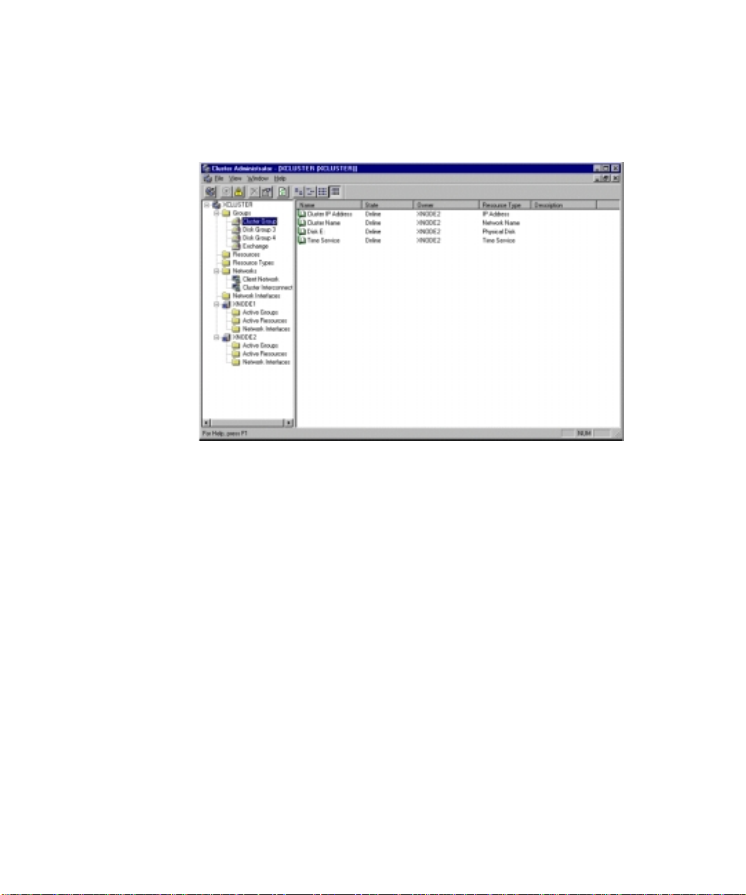
3. If the cluster has been created correctly, the names of both server nodes
appear on the l eft side of the Cluster Administrator window (see Figur e
1-1). Note the cluster name.
Figure 1-1. Microsoft Cluster Administrator
Verifying Server Node Failover
NOTE: When running the failover test, start with the least complex test. Do not run any
client activity while testing failover events.
Follow these steps to verify failover of a server node:
1. From the desktop on both server nodes, select Start, Programs,
Administrative Tools (Common), Cluster Administrator.
2. When prompted for the cluster or serve r name, enter the name or IP
address of one of the serve r nod es.
3. Make sure all predefined resources and groups are online. Verify that
some of the resources and groups are owned by the serve r node you are
powering down so that a failure event will result in failover of resources
and groups.
Page 20

1-10 Compaq ProLiant CL1850 Software User Guide
4. Power down one of the server nodes.
5. Within several seconds, Cluster Administrator running on the surviving
server node should bring online all of the predefined resources and
groups that were previously owned by the powered-down server node.
If, after a minute, nothing appears to have happened, refresh the sc reen
by selecting Refr esh (F5).
Verifying Network Client Failover
Now that you have verified that each server node is running correctly as a part
of the cluster , the next step is to verify that network cl ients can interact with
the cluster.
The followi ng steps will le ad you through this validation procedure.
1. Ensure bot h server nodes are running, and verify, using Cluster
Administrator, that all groups and res ources are online.
2. For each hard drive in the shared storage, Cluster Server automatically
creates a cluster group that consists of a single resource, the hard drive.
Using Cluster Administrat or, add an existing IP addre ss as another
resource to one of these grou ps. (DO NOT use t he Cluster Group.) Save
the changes and return to the main Cluster Administrator screen.
3. Open a DOS window on a ne twork client machine.
4. Ensure the network client can access the IP address, added in Step 2.
From the network client, e xe cute a PING command, using the cluster IP
address as the argument.
NOTE: Regardless of whether you are using WINS or DHCP, you can execute the DOS
command “PING” to check the connection.
The client has successfully accessed the cluster resource if you get a
response similar t o:
Reply from <IP Address>: bytes=xx time=xxxms TTL=xx.
The client has not successfully accessed the cluster resource if you get a
response of:
Reply from <IP Address>: Destination host unreachable
5. Following the completion of the PING comma nd, use Cluster
Administrator to perform a manual failover of the cluster group that
contains the IP address.
6. After the manual failover completes, execute the PING command again.
Page 21

System Setup and Configuration for Microsoft Windows NT S/E 4.0 1-11
7. As soon as the other server node brings the cluster group online, a
response similar to the one n ot ed in Step 4 should be returned. If the
client successfully accessed the failed over IP address, your cluster is
working. If t he client was unsuccessful, eit her the cluster group was not
configured correctly, t he failover did not occur, or the PING comma nd
was performed before the failover activity completed.
NOTE: To verify a more extreme case, rather than fail over the IP address, power down
the primary cluster server node and verify that the resource fails over to the other server
node.
Setting Up Cluster Groups and Cluster Resources
You have now set up and configured all y our clustering hardware. Microsoft
Windows NT Server 4.0, Enterprise Edition and Cluster Server are installed on
both servers. You have done some minima l validation of your cluster and
everything is working as planned. Now i t is time to set up your applications to
utilize the capabilities of clustering.
If you have defined your cluster needs correctly and determined how to fit
your applications and environment into a cluster, configuring your applications
will be a straightforward task.
Although details of these procedures are beyond the scope of this guide,
several doc uments are avai lable from both Microsoft and Compaq to assist
you with these final steps.
The best source of information concerning the steps to configure cluster
groups and cluster resourc es is Micros oft’s Cluster Serv er Administr at or’s
Guide. Refer to that guide for detailed setup information.
Compaq has worked directly with several application vendors throughout the
developmen t of Compaq ProLi ant Clusters. As a result of thes e efforts,
Compaq provides a number of Integrati on TechNotes t o assist you with
installing these applications in a Compaq ProLiant cluster environment.
The following TechNotes are included with your Compaq ProLiant cluster
documentation:
■ Microsoft File and Print Service Failover Using Microsoft Cluster
Server (MSCS)
■ Microsoft Internet Information Server (IIS) 3.0 Service Failover Using
MSCS
Page 22

1-12 Compaq ProLiant CL1850 Software User Guide
■
Microsoft IIS 3.0 Resource Failover Usi ng MSCS
The following Integration TechNotes are available on the Compaq website:
http://www.compaq.com
Visit the Com paq website to download the most current versions of these and
other techni cal documents:
■ Microsoft SQL Server Service Failover Using MSCS
■ Oracle Service Failover Using MSCS
■ Resource Failover Using Oracle FailSafe 2.0x and MSCS
■ Lotus Domino Server 4.51 Service Failover Using MSCS
Page 23

Chapter 2
System Setup and Configuration
for Novell NetWare
Have the following items available as you configure your Compaq
ProLiant CL1850.
■ Hardware Configurati on and Installation Poster
■ Compaq SmartStart and Server Management CD
■ Compaq SmartStart Installation Poster
■ Compaq Insight Manager Installation Poster
■ Operating system documentation
■ Novell NetWare 4.2 or NetWare 5
■ Novell High Availability Server for NetWare 4.2 or Novell Cluster
Services for NetWare 5
Page 24

2-2 Compaq ProLiant CL1850 Software User Guide
Configuring the System
The sections below provide instruction s for configuring your ProLiant CL1850
system.
Preconfiguration Checks
1. Be sure you have sufficient software rights to install the operating
system and software applications on each server.
2. All hardware must be installed before y ou install the software.
Configuring the Shared Storage Array
1. Place the appropriate number of disk drives in the shared storage array
for your RAID configurati on and drive si ze requirements.
2. Power up the shared storage array.
3. Configure the shared storage array using the CR3 500 Configuration
Utility. For instructions on using this utility, refer to Chapter 3,
“CR3500 Configuration Utility.”
Configuring Server Node 1
1. Apply power to the shared storage area and boot server node 1 with the
SmartStart and Support Software CD in the CD-ROM drive.
2. When the system boots, you will see the Select Language screen. Select
which lang uage you would like to use and follow the installation
process.
3. When prompted to select the installation pat h, select the Assisted
Integration Path. Follow the guided installation process. If you need
help, refer to the online help by clicking on the help button.
After the operating system has been selected, SmartStart runs the
System Configuration Utility and configures the server node’s hardware.
It is very important that the adapter card in each server node connected
to the shared storage RAID cont roller have a unique SCSI ID number.
4. To verify or change the SCSI ID number after the system configuration
is done, select Review or Modify Hardware Sett ings then press Enter.
This allows you to see all of the hardware settings.
5. Select Step 3: View or Edit Details.
Page 25

System Setup and Configuration for Novell NetWare 2-3
6. Arrow down to Compaq 64-Bit D ual Channel Wide Ultra2 SCSI
Controller (Port1). Underneath this heading is a s ubheading titled SCSI
ID. To change the SCSI ID setti ng, highlight the SCSI ID opti on then
press Enter. After making a new selection, press Enter to accept the
change.
IMPORTANT: Make a note of the SCSI ID setting. When server node 2 is configured, it
cannot have the same ID as server node 1. For example, if server node 1 is set for SCSI
ID 6 then server node 2 must be set to ID 7.
7. Press F10 to exit.
8. Select Step 5: Save and Exit, then press Enter.
9. The Product Selection Window appears. Follow the guided installation
process. If you need help refer to the online help by clicking on the Help
button.
10. Once NetWare has been loaded, type Load Install (for NetWare 4.2) or
Nwconfig (for NetWare 5) at the NetWare Console prompt. This allows
you to set up the NetWare disk partitions and to create or modify the
volumes that the system will use.
NOTE: The Compaq 53c876 is the local controller for the internal hard disk drives on the
server nodes. The Compaq 53c896 is the controller device for the shared array controller.
Always install the SYS volume on the local non-shared drives.
Configuring Server Node 2
1. Press Print Screen to access the KVM (Keyboard/Video/Mouse) switch
and choose server node 2 from the list.
For detailed instructions on using the KVM switch, refer to the Compaq
ProLiant CL 1850 User Guide.
2. Boot server node 2 with the SmartStart CD in the CD-ROM drive.
3. When the system boots, you will see the Select Language screen. Select
which lang uage you would like to use and follow the installation
process.
Page 26

2-4 Compaq ProLiant CL1850 Software User Guide
4. When prompted to select the installation pat h, select the Assisted
Integration Path. Follow the guided installation process. If you need
help, refer to the online help by clicking on the Help button.
After the operating system has been selected, SmartStart runs the
System Configuration Utility and configures the server node’s hardware.
It is very important that the adapter card in each server node connected
to the shared storage RAID cont roller have a unique SCSI ID number.
5. To verify or change the SCSI ID number after the system configuration
is done, select Review or Modify Hardware Sett ings then press Enter.
This allows you to see all of the hardware settings.
6. Select Step 3: View or Edit Details.
7. Arrow down to Compaq 64-Bit D ual Channel Wide Ultra2 SCSI
Controller (Port1). Underneath this heading is a s ubheading titled SCSI
ID. To change the SCSI ID setti ng, highlight the SCSI ID opti on then
press Enter. After making a new selection, press Enter to accept the
change.
IMPORTANT: Make a note of this setting. When server node 2 is configured, it cannot
have the same ID as server node 1. For example, if server node 1 is set for SCSI ID 6 then
server node 2 must be set to ID 7.
8. Press F10 to exit.
9. Select Step 5: Save and Exit, then press Enter.
10. The Product Selection Window appears. Follow the guided installation
process. If you need help, r efer to the onl ine help by clicking on the
Help button.
11. Once NetWare has been loaded, type Load Install (for NetWare 4.2) or
Nwconfig (for NetWare 5) at the NetWare Console prompt. This allows
you to set up the NetWare disk partitions and to create or modify the
volumes that the system will use.
12. After the operating system has been successfully insta lled on both server
nodes, install the appropriate Novell clustering software.
Page 27

System Setup and Configuration for Novell NetWare 2-5
Configuring the Cluster for NetWare 4.2
Novell High Availability Server (NHAS) is the software needed to run the
clustering a spect of the ProL iant CL1850 when runnin g N etWare 4.2. This
software must be installed after each server node has NetWare 4.2 loaded and
at least one volume from the shared storage array has been mounted to each
server node. NHAS will allow you to accomplish the following:
■ Configure the cluster
■ Pause the cluster
■ Manual failover
■ Manual failback
■ Automatic failover
■ Automatic failback
For instructions on NHAS installation and detailed use of these functions,
please refer to the
Preparations for Installing NHAS
Novell High Availability Server User’s Guide from Novell.
The following is a list of preparations needed prior to installation of NHAS.
■ Check network connections to and from each server using Display
Servers command at NetWare console.
■ Use the Config command to check all IP addresses and to make sure
there is a network connection bounded to the IPX protocol for t he Direct
Link. Label this network port as such for simplicity in recognition
during the NHAS installat ion. A second network connection shoul d
exist for public NetWare Link.
■ Be sure to allocate and mount at least one shared volume for each server
by using the Volume Options in the Install utility. Multiple volumes will
imply the same rule. Try to gauge which applications will be installed so
the volumes’ File Compre ssion and Block Suballocation settings are
appropriate. Otherwise, you will need to reinstall NHAS later.
■ Each server in the cluster must have an internal hard drive that is not
part of the shared subsystem. A SYS: volume on the shared subsystem
would be confusing and potentially da maging.
Page 28

2-6 Compaq ProLiant CL1850 Software User Guide
■
NetWare volumes can span multiple drives. When a volume spans more
than one drive, all of the drives that it spans must be shared or all of
them must be not shared. Otherwise if one drive fails, there will be no
access to the volume from either cluster server.
■ NHAS cluster server will function within different containers in the
NDS tree, but they must reside in the same directory tree to ensure
smoother failover of NDS resource objects.
■ It is not necessary for servers in the cluster to contain NDS replicas as
long as multiple trusted replicas exist on the network. If one server in
the cluster contains a trusted NDS replica, then for NDS availability
reasons, both servers should contain a replica.
NOTE: You must install the latest NetWare Support Pack and then the NSSD before
installing NHAS.
Installation of NHAS
NHAS is installed by mounting the NHAS CD on a server and using the
CD-Mount HA command, then entering the following on the console.
LOAD HA:HASERVER/HASINST
When prompt ed to select the other server node of the cluster pair, enter the
“V” command at the NetWare console of the other server node. From the first
server node, you will then select the Direct Link. When the file copy is
complete, finish the installation by pressing Enter, Down, Exit, and Restart
both servers.
Page 29

Verifying Functionality of the Cluster
Now that the software is installed, you can verify the creation of the cluster
from the NHAS Console. All three links under Connection Status will show
Connected. See Figure 2-1.
System Setup and Configuration for Novell NetWare 2-7
Figure 2-1. NHAS: Connected
Verifying Direct and NetWare Links
To test Direct Link Disconnect:
1. Remove the network cabl e from the server’s network card to which
Direct Link is dedicated. The Direct Link status on the NHAS screen
should change from Connected to Not Connected.
2. Reconnect the network cable to the network card. The Direct Link status
should change from Not Connected to Connected.
Page 30

2-8 Compaq ProLiant CL1850 Software User Guide
To test NetWare Link Disconnect:
1. Remove the network cabl e from the server’s network card to which
NetWare Link is dedicated. The NetWare Link status should change
from Connec t ed to Not Connected.
2. Reconnect the network cable to the network card. The NetWare Link
status should change from Not Connected to Connected.
Verifying Server Node Failover
When running the failover test, it is recommended to start with the least
complex test, so do not run any client activity while testing failover eve nt s.
For instructions on testing NHAS Failover, please refer to the NHAS user’s
guide from Novell.
Configuring the Cluster for NetWare 5
Do the following preparations before installation.
1. Install all necessary Support Packs and NSSDs.
2. Ten MB of free space that is not part of an NSS or DDFS partition on
the shared storage array is required for the split brain partition. Be sure
this partition can be readily seen through both server nodes.
3. If you want to zone the intra-cluster links and separa t e it from the main
public netw ork link, be sur e to assign it an IP address of a different
subnet on a NIC through NetWare. You will have the option to choose
the specific NIC during NCS installation.
The Novell Cluster Services Installation creates a new cluster object and
installs Novell Cluster Services software o n the ser ver n odes you specify to be
part of your cluster. This installation is done from a remote client workstation
machine.
1. Insert the NCS CD into the CD-ROM drive o n the client workstation
with administration rights to the directory tree to which the server nodes
reside.
2. From the initial splash screen, launch the Novell Cl uster Services
installation. Continue through the in stallation screens until you get to the
screen that prompts you to create a new cluster.
3. Select Create a New Cluster. Then click Next.
4. Enter a name for the new cluster object you are cre ating and specify the
directory tree and context where you want it created. Then click Next.
Page 31

System Setup and Configuration for Novell NetWare 2-9
5. Enter the name of the server node you want to add to the cluster, or
browse and select one from the list, and then click Add to Cluster.
Repeat this step for the second server node to add to the cluster. When
you add a server node to a clus t er, Novell Cluster Services automatically
detects the server node’s IP address. If the server node you are adding
has more than one IP address, y ou will be prompted to select t he IP
address you want Novell Cluster Services to use.
6. Specify that your cluster has a shared disk system, then select the drive
where you want the small cluster partition created. Novell Cluster
Services requires a small cluster partition on the shared disk system.
You are also given the option of mirroring the parti t ion for great er fault
tolerance.
IMPORTANT: You must have a small amount of free space on one of the shared disk
drives to create the cluster partition. If no free space is available, the shared disk drives
will be unusable by Novell Cluster Services.
7. Continue through the final installation screen. The Novell Cluster
Services installation program will then create a new cluster for you and
add the server nodes you specified in the install to the cluster.
After creating a new cluster, you now need to create cluster resources and
configure t hose resources. You also should consider adding NetWare volumes
to the cluster and creating cluster resource templates.
Verifying NCS Cluster Creation
Create a simple application cluster resource object via a “load monitor.” Be
sure to add the server nodes to the resource so the resources can startup. Start
up the resource and force a migration. On the local server console screens you
should be able to see the monitor utility load and unload.
Create a simple volume object (note you will need to create a NSS volume
from NetWare first). Be sure to add the server nodes to the resource so the
resources can startup. Start up the resource and force a migration. On the local
server consol e screens you should be able to see the monitor utility load and
unload.
Page 32

Chapter 3
CR3500 Configuration Utility
This chapter provides instructions for using the Compaq CR3500
Configuration Utility and describes methods to configure your CR3500
controller quickly and easily. The CR3500 Configuration Utility is located on
the Compaq SmartStart and Support Software CD.
The utility uses a graphical user interface (GUI) to help you configure the
CR3500 controller. You can use the utility to configure a controller initially or
to reconfigure a controller.
The CR3500 Configuration Utility can create arrays (a group of physical
drives that are similar in size) called logical drives. Logical drives are created
using the CR3500 Configuration Utility’s A dd L ogical Drive Wizard. You can
create:
■ Single-device arrays (JBODs)
■ Striped arrays (RAID 0)
■ Mirrored arrays (RAID 1)
■ Striped mirrored arrays (RAID 0+1)
■ Striped parity arrays with fixed parity disk (RAID 4)
■ Striped parity arrays w ith floating parity disk (RA ID 5)
For more information on RAID levels, refer to the Online Help.
Page 33

3-2 Compaq ProLiant CL1850 Software User Guide
This chapter includes the following sections:
■ Online Help
■ Before You Begin
■ CR3500 Configuration Utilit y Feat ures
■ Configuration Procedures
■ Error and Warning Messages
The CR3500 Configuration Utility:
■ Uses eas y-to-unders tand graphics to illustrate controller configuration
■ Uses a wiz ard that guides you through the confi guration proc ess
Online Help
Press the F1 key to activate context-sensitive, online help for each screen.
Help is also available by clicking the Help heading on the toolbar. A status bar
at the bottom of the screen also displays help messages describing the c urrent
selection.
Before You Begin
Before a first-time installation and configuration of the system, complete the
following:
■ Install a redundant CR3500 controlle r (optional). To install a redundant
CR3500 controller, refer to the Compaq ProLiant CL1850 User Guide.
■ Determ ine which faul t tolerance m ethod and logical drive configuration
you want to use. For more information on RAID levels, refer to the
Online Help.
Page 34
CR3500 Configuration Utility Features
There are two methods you can use to run the CR3500 Configuration Utility.
■ SCSI connection—Th is option is only for systems runni ng
Windows NT.
■ Serial cable connection—For server nodes not running Windows NT , a
separate system running Windows 95/98/NT is require d. A serial cable
is used to connect the separate system to the CR3500 RAID controller
through a connection in the back of the shared storage area.
SCSI Connection
The system mu st be running Windows NT to connect online via the SCSI
interface.
1. Insert the SmartStart CD into the server node.
2. From Windows NT Explorer, go to the CR3500 direct ory on the
SmartStart CD and run SETUP.EXE. This will install the CR3500
Configuration Utility to the server node.
3. Go to Start, Compaq System Tools, CR3500 Utility t o run the utilit y.
CR3500 Configuration Utility 3-3
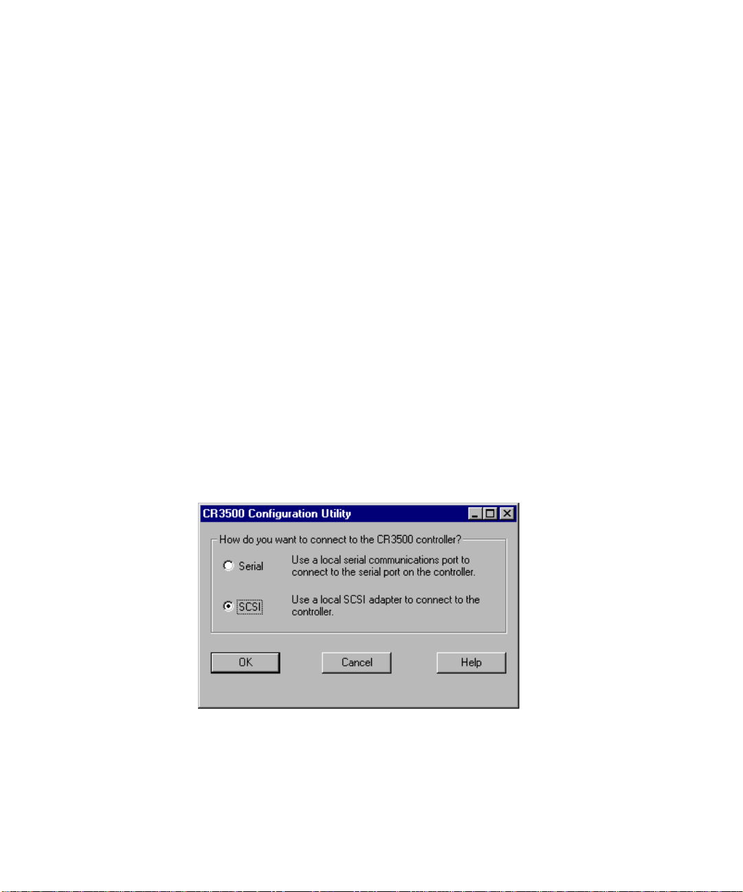
4. A connection window appears (Figure 3-1).
Figure 3-1. CR3500 Configuration Utility SCSI connection
5. Select SCSI and click OK. You will then be taken to the main window
of the utility.
Page 35
3-4 Compaq ProLiant CL1850 Software User Guide
Serial Connection
This method uses a separate system running Windows 95/NT.
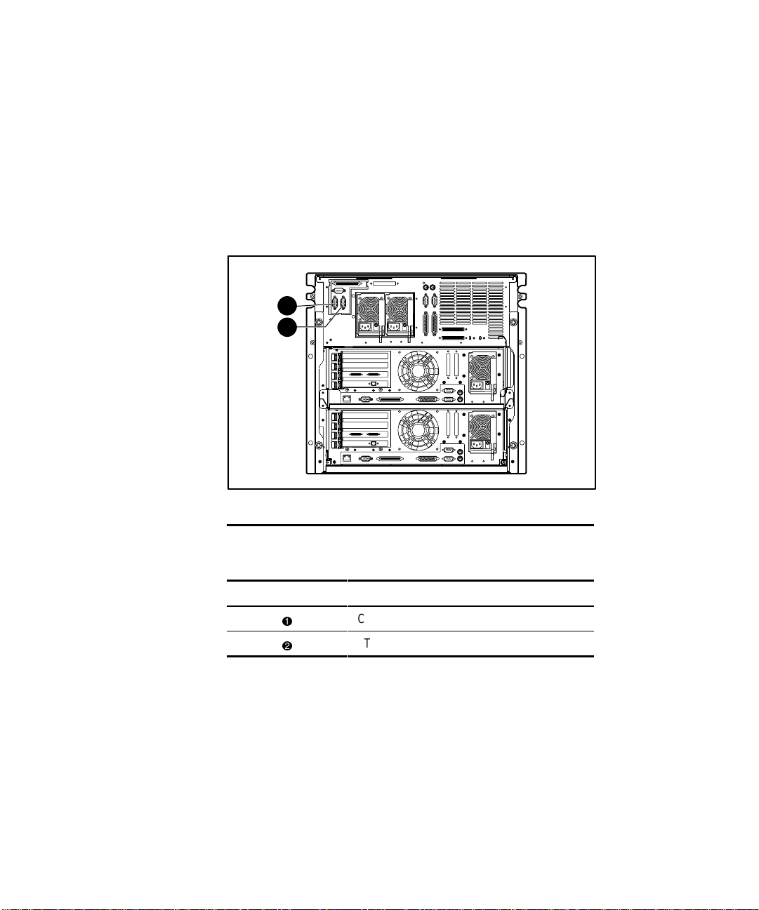
1. Connect the Windows 95/ 98/NT system to t he port labeled CTRL-1 on
the back of the shared storage area using a serial cable. If using
redundant controllers, connect anothe r serial cable from the Win95/NT
system to the port labeled CTRL 2. See Figure 3- 2 for connection
locations.
1
2
Figure 3-2. Shared storage array ports
Table 3-1
Shared Storage Arra y Connection
Identifier Description
1
2
2. Insert the SmartStart CD into the system r unning Windows 95/NT.
3. From Windows Explorer, go to the CR3500 directory on the SmartStart
CD and run SETUP.EXE. This will install the CR 3500 Configuration
Utility.
4. Go to Start, Compaq System Tools, CR3500 Utility t o run the utilit y.
CTRL-1 connection (top controller)
CTRL-2 connection (bottom controller)
Page 36
CR3500 Configuration Utility 3-5
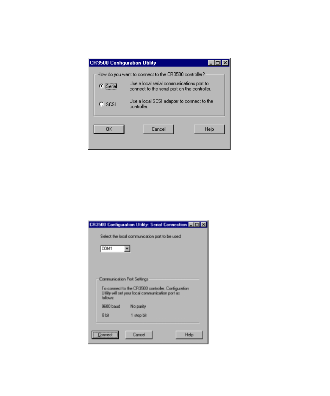
5. A connection window appears (Figure 3-3).
Figure 3-3. CR3500 Configuration Utility Serial connection
6. Select Serial, then click OK.
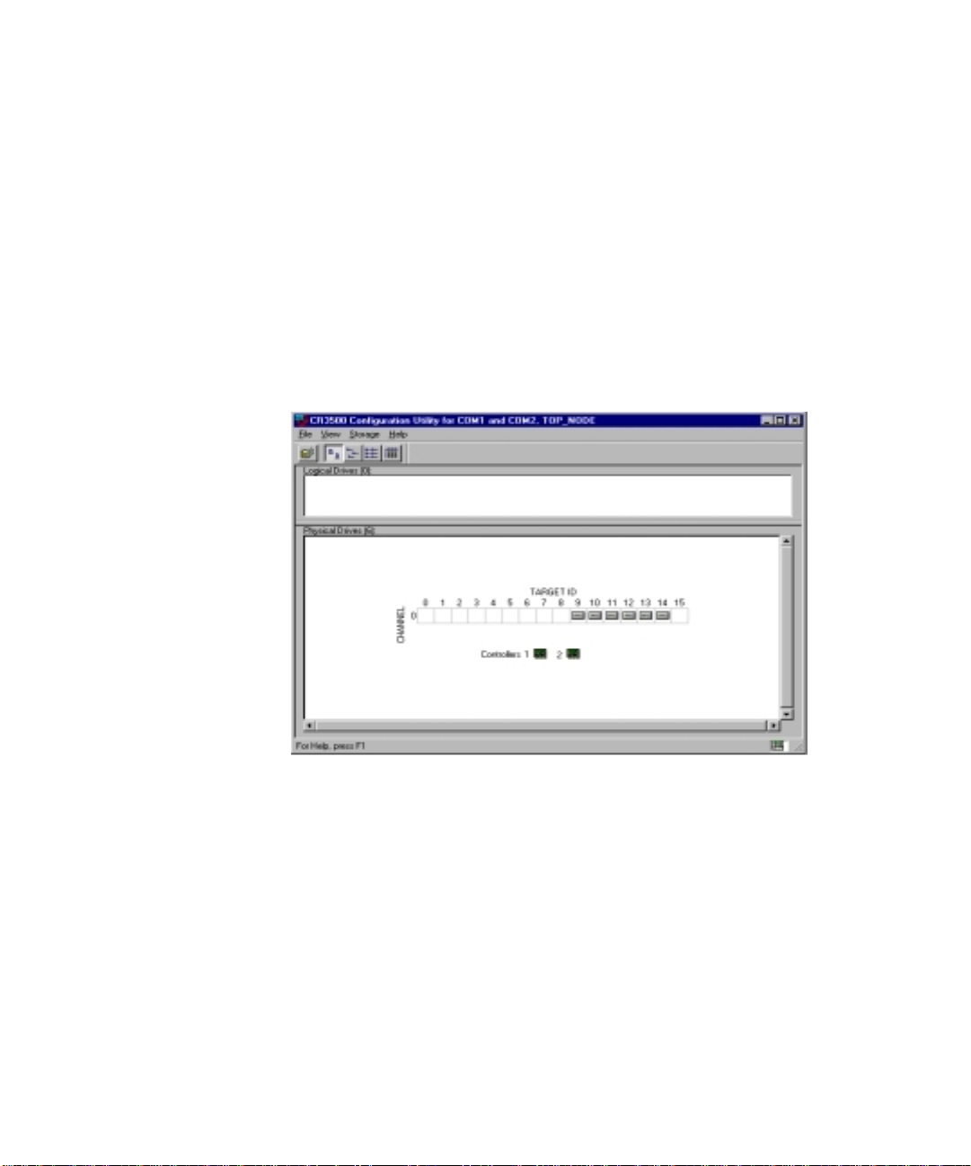
7. Next you will see the Serial Connection window (Fi gure 3-4). Choose
the COM port (usually COM1) used to make the connection to the
shared storage array. Click Connect. If you are using a dual controller
setup, a second serial connection window will appear and you must
select the COM port (usually COM2) for the second controller. After
Connect is clicked, the main window will appear.
Figure 3-4. CR3500 Configuration Utility: Serial Connection
Page 37
3-6 Compaq ProLiant CL1850 Software User Guide
Configuration Utility Features
Main Window
The CR3500 Configuration Utility main window (Figure 3-5) has four areas:
■ The menu bar
■ The tool bar
■ The logic al drives window
■ The physi cal drives window
Figure 3-5. CR3500 Utility main window
Drop-Down Menus
The main window has menu bars and drop-down menus. For more
information, see the “Main Window Menu Ba r” section later in this chapter.
Each drop- down menu pres ents a group of related functions.
Menu and Command Access Methods
You can use the mouse or the keyboard to access menus and commands. For
keyboard access, simultaneously press the Alt key and the underlined letter in
the name of the menu. Next, press the underlined letter of a command name
shown in the drop-down list.
Page 38
Shortcut Menus
Frequently used commands can also be accessed by clicking the right mouse
button on the system, logi cal drive, de vice, or folder icon.
Main Window Menu Bar
The menu bar (Figure 3-6) provides cascading menu sele ctions for most of the
functions you can perform in the configuration utility.
There are f our, drop-dow n menus in the m enu bar:
■ The File menu
■ The View menu
■ The Storage menu
■ The Help menu
You can reach any menu command using a keyboard shortcut. Each shortcut is
formed by pressing the Alt key along with the letter underlined on the menu
bar. You can reach sub menu commands by appending an additional character,
shown underlined in the sub menu’s menu bar.
CR3500 Configuration Utility 3-7
Figure 3-6. Main window menu bar
For more information on these menus and their commands, access the Online
Help by pressing F1.
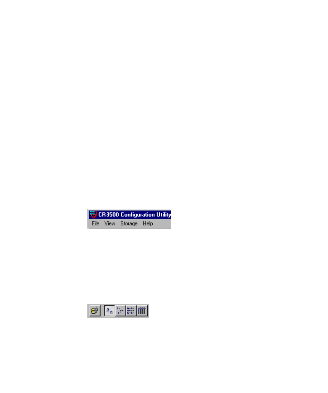
Main Window Toolbar
The tool bar (Figure 3-7) provides buttons with which you can perform many
of the functions available in the CR3500 Config uration Utility.
Figure 3-7. Main window toolbar
Page 39
3-8 Compaq ProLiant CL1850 Software User Guide
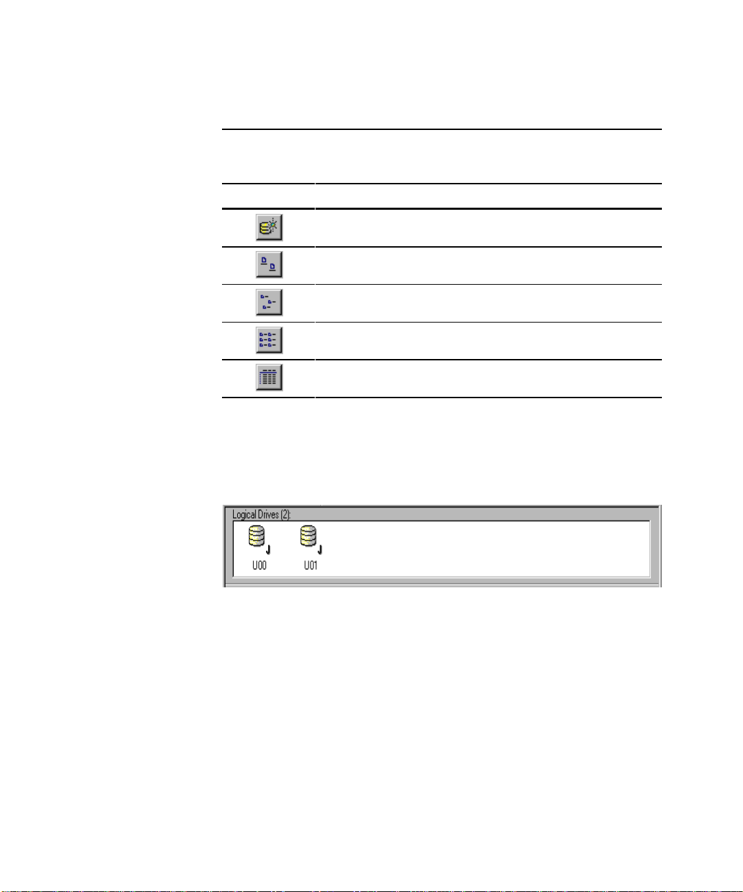
Each tool bar icon is described in Table 3-2.
Icon Icon Name Description
Add logical drive button Enables you to add a new logical drive
Large icons button Displays your logical drives as large
Small icons button Displays your logical drives as small
List button Displays your logical drives in a list of
Details button Displays your logical drives in a detailed
Logical Drives Window
Table 3-2
Storage Window Tool Bar Icons
to your storage subsystem
icons
icons
small icons
list
The Logical Drives win dow (Figure 3-8) provides detailed information a bout
the logical drives you ha ve configured in your storage subsystem.
Figure 3-8. Logical Drives window
View Options
You have fo ur options for viewing the information in the Logical D rives
window:
■ Large icons
■ Small icons
■ List
■ Details
Page 40

CR3500 Configuration Utility 3-9
Large Icons, Small Icons, and List Views
If you choose t he Large Icons, Small Icons, or List options in the Logical
Drives View menu, the pro gram uses icons to indicate the underlying structure
of the logical drives in the Logical Drives window. The logical drive types and
their corresponding icons are shown in Table 3-3.
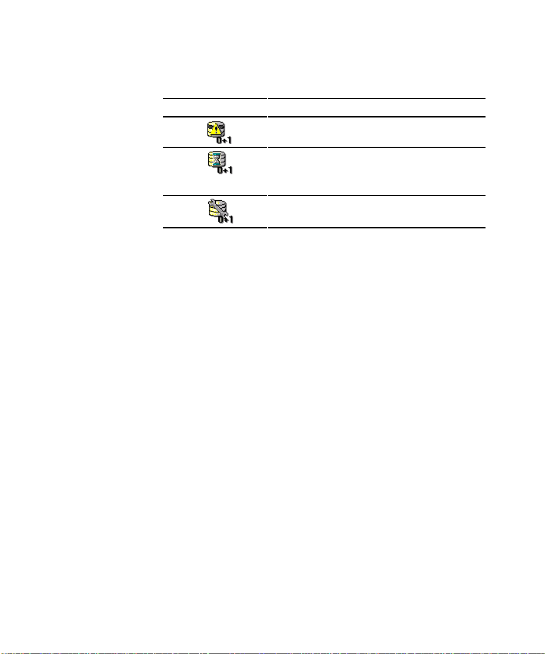
Table 3-3
Logical Drive Types
Logical Drive Type Description
Indicates a JBOD (single-disk) logical drive
Indicates a RAID 0 logical drive
Indicates a RAID 1 logical drive
Indicates a RAID 0+1 logical drive
Indicates a RAID 4 logical drive
Indicates a RAID 5 logical drive
The program also uses icons to indicate the status of the logical drives in the
Logical Drives window. The logical drive status and corresponding icons are
shown in Tabl e 3-4.
Table 3-4
Logical Drive Status
Logical Drive State Icon State Description
Good Logical drive is operating normally.
Failed Logical drive is not working.
continued
Page 41
3-10 Compaq ProLiant CL1850 Software User Guide
Table 3-4
Logical Drive Status
Logical Drives State Icon State Description
continued
Details View
If you choose the Details option in the V i ew menu, the l ogical drive window
displays four information fields:
■ Name—The name the utility has given your logical drive
■ State—The current operational state of the logical drive
Reduced One physical drive in a logical drive has
failed.
Initializing The program is creating a starting parity
for a logical drive that has parity, or is
starting data for a logical drive that does
not have parity.
Reconstructing A failed physical drive’s data is being
regenerated on a spare disk.
■ Capacity—The maximum amount of data, in bytes, that the logical drive
can contain
■ RAID level—The underlying structure of the logica l drive
NOTE: You can change the width of an information field by dragging on one of its
borders.
Logical Drives Propert y Sh eets
You can view very detailed attributes of your logical drives by accessing their
property sheets. You can access a logical drive’s property sheet directly by
double clicking the logic al drive’s icon in any view. You can also right-click
the icon and select Properties from the shortcut menu. For more information
regarding l ogical drive properties, r efer to the Online Help.
Locating Logical Drive Memb e rs
You can locate the members of any logical drive by clicking on the logical
drive icon in the Logical Drive window. The drive’s members are shown as
shaded physical drive icons in the Physical Drive window.
Page 42

Physical Drives Window
The Physical Drives window (Figure 3-9) provides detailed information about
the physical drives you have configured in your storage subsys tem.
Figure 3-9. Physical Drives window
CR3500 Configuration Utility 3-11
Page 43
3-12 Compaq ProLiant CL1850 Software User Guide
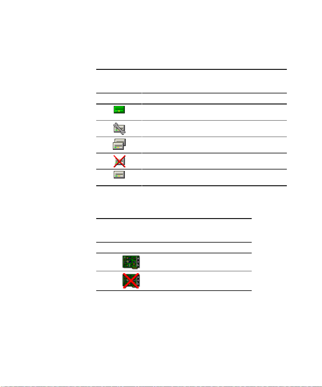
The CR3500 Configuration Utility uses icons to indicate the status of the dis ks
in the disk window. The physical drive states and corresponding icons are
shown in Tabl e 3-5.
Drive State Icon State Description
Good Physical drive is operating normally as part of a
Reconstructing Reconstruction data is being written to this
Spare Physical drive is available to replace a failed
Failed Physical drive is not available but is installed.
Available Physical drive is available for use in a logical
Icons representing the Shared Storage RAID controllers are arranged just
below the physical drives. The utility uses icons to indicate the status of yo ur
controllers, as shown in Table 3-6.
Table 3-5
Physical Drive States
logical drive.
physical drive.
physical drive that is a group member.
drive or as a spare.
Table 3-6
Controller status
Controller Status Icon Description
Indicates an operational controller
Indicates a controller that is not operational
Page 44

Configuration Procedures
Adding a Controller
A second CR3500 controlle r may be added for redundancy of the shared
storage array. To install a second controller, refer to the Compaq
ProLiant CL1850 User Guide.
Configuring the CR3500 Controller
Each installed controller has configuration properties that can be modified
using the CR3500 Configuration Utility. When the contr ollers are installed, the
utility assigns them default settings. You can cha nge these settings to meet
your own needs.
To access the controller properties, right-click the controller icon and select
Properties. You may also select the controller and then choose Properties from
the File pull-down menu.
The Controller Properties screen (Figure 3-10) appears showing the four
property tabs. They are:
■ General
CR3500 Configuration Utility 3-13
■ Host Ports
■ Environment
■ Cache
Page 45

3-14 Compaq ProLiant CL1850 Software User Guide
Figure 3-10. Controller Properties window, General tab
The General tab has the following properties.
■ System Name—Show s the system name as it is known by the operating
system.
■ Failover Mode—Shows the failover mode selected: high pe rformance
(active/active), high availability (active/passive), or stand-alone (single
controller). High availability is only available with two controller s.
■ Read-ahead cache limit—Enter the desired read-ahead limit (0-16). If
you enter 0, the read-ahead is disable d. Each increment equals 32 blocks
of data that are read ahead in the cache. For example, 2 would equal
64 blocks read ahead.
■ Controller mode—Show s the controller mode, which is active or
unavailable.
■ Rebuild rate—Enter the desired rebuild rate, which ranges from
1 to 100. The controller rebuilds while it handles I/O activity. A rate
below 50 emphasizes I/O response over the RAID rebuild. A rate above
50 puts a higher priority on the RAID rebuild at the expense of I/O
activity.
Page 46

CR3500 Configuration Utility 3-15
■
Create rate—Enter the desired create rate, which ranges from 1 to 100.
The controller creates RAID sets while it handles I/O activity. A rate
below 50 emphasizes I/O response over the RAID set creation. A rate
above 50 puts a higher priority on the RAID set creation at the expense
of I/O activity.
■ Firmware revision—Shows the current software revision.
■ Serial number—Shows the serial number of the controller.
■ Connection type—Show s the connection type, which can be serial or
SCSI.
Page 47

3-16 Compaq ProLiant CL1850 Software User Guide
The next tab, Host Ports (Figure 3-11), has the followi ng properties.
Figure 3-11. Controller Properties window, Host Ports tab
■ Failover Mode—Enter the desired failover mode: Performance
(active/active) or High Availability (active/passive). High availability is
only available with two controllers. If two control l ers are present, both
must be set to the same failover mode.
NOTE: Compaq recommends running in active/active mode only.
■ Host I/O channel 0—Enter the desired host I/O channel mode, which
can be active or passive.
■ Channel 0 Target ID—The physical addres s a bus initiator uses to
connect with a bus target. Each bus target is assigned a unique target
address. You must select an I D between 0 an d 15 for a 16-bit module, or
between 0 and 7 for an 8-bi t module. Make sure the ID you select does
not conflict with other IDs. Target IDs are also referred to as the SCSI
ID.
NOTE: Compaq recommends using the default values for the Channel 0 Target ID.
■ Bus width—E nt er the desired bus width, 8 bit or 16 bit.
Page 48
CR3500 Configuration Utility 3-17
■
SCSI transfer rate—Enter the desired SCSI transfer rate. You can
choose from 5 MB to 40 MB.
■ Tag queuing—If your host adapter sup ports tag queuing check here . Tag
queuing permits each initiator to have multiple c ommands outstanding
and each target to optimize the commands it receives.
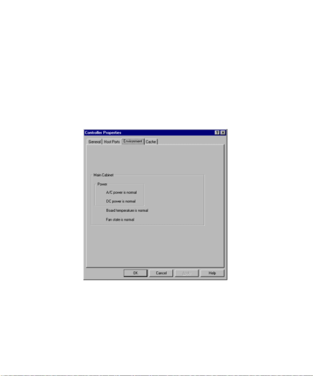
The Environment tab (Fi gure 3-12) monitors the f ollowing items:
■ Power
■ Temperature
■ Fan State
Figure 3-12. Controller Properties window, Environment tab
Refer to the Online Help for more information regarding each area’s warning
icon and meaning.
Page 49
3-18 Compaq ProLiant CL1850 Software User Guide
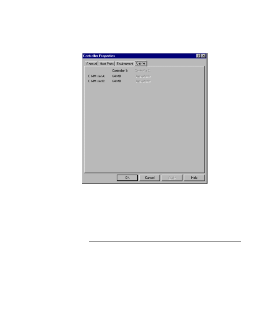
The Cache tab (Figure 3-13) indicates the cache memory size for each
occupied slot in a controller’s memory.
Figure 3-13. Controller Properties window, Cache tab
Adding Physical Drives
The system’s CR3500 RAID Controllers must recognize the physical drives in
the shared storage area before you can create logical drives from them. The
controller will recognize all physical drives at start up. To add physical drives
to your configuration after the controll er has started, follow these st eps:
IMPORTANT: Before adding physical drives that have previously been used by another
ProLiant CL1850, it is necessary to delete any configuration settings on the drives. Failure
to do so can cause conflicting RAID settings on the CR3500 controller.
1. Physically add the drives to the system.
2. Run the CR3500 Configuration Utili ty to configure the drives.
NOTE: You cannot increase the capacity of an existing logical drive.
Page 50
3. From the Main window, click Physical Drive, then click New.
4. The Add New Physical Drive Window appears. Enter the channel
number and Target ID for the new physical drive. The Target ID is
displayed on the gr id.
NOTE: An alternate method for adding drives is to click on an empty cell in the grid, then
right click and select New. This presents the Add New Physical Drive window with the
channel number and target ID currently assigned.
5. Click the OK button. The program adds your physical drive to your
configuration and refre shes the main screen.
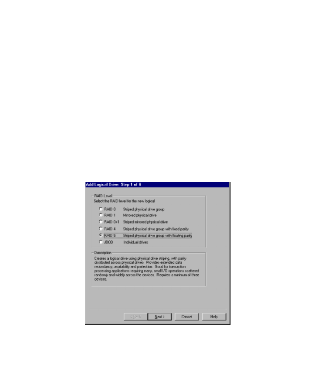
Adding Logical Drives
From the Storage pull-down menu, select Add Logical Drive. There is a
six-step Wizard to assist you in adding a logical drive.
1. Select the RAID level for the new logical drive (Figure 3-14). Click the
Next button to continue.
CR3500 Configuration Utility 3-19
Figure 3-14. Add Logical Drive: Step 1
Page 51
3-20 Compaq ProLiant CL1850 Software User Guide
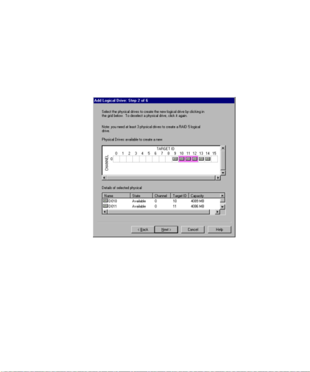
2. Select the physical drives for the new logical drive (Figure 3-15). The
number of physical drives you choose will determine the amount of
storage that will be available for the new logical drive. To select a
physical drive, click on an available physical drive and it will be added
to the selected physical drive list.
The Next button is disabled until the minimum number of disks is
chosen.
Figure 3-15. Add Logical Drive: Step 2
Page 52
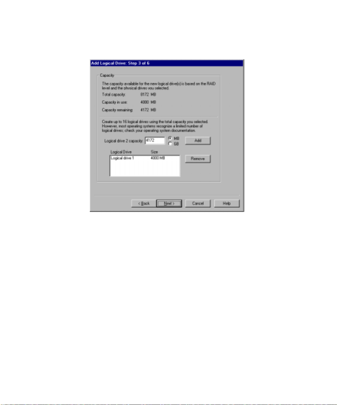
CR3500 Configuration Utility 3-21
3. Add the capacity for the logical drive (Figure 3-16).
Figure 3-16. Add Logical Drive: Step 3
■ To create a single logical drive using the total capacity available, click
Add. The capacity remaining changes to 0. The new logical drive will
appear in the bottom window, along with its capacity size. Click Next to
continue.
■ To create more than one logical drive, enter a number less than the
amount appearing in the Logical Drive Capacity window and click Add.
The capacity remaining changes to reflect the new amount of capacity in
use. Repeat this step if you want to create another logical drive, or click
Next to continue.
Page 53

3-22 Compaq ProLiant CL1850 Software User Guide
4. Define the strip size and the host port f or the new logical drives
(Figure 3-1 7). Click Next to continue. For more information on strip
size and host ports, refer to the Online Help.
Figure 3-17. Adding Logical Drive: Step 4
Page 54

CR3500 Configuration Utility 3-23
5. Select a Logical Unit Number (LUN) for the logical drive (Figure 3-18).
The Step 5 screen also gives yo u the option of enabling the Writeback
Cache to improve host performance. For more information on LUNs and
Writeback Cache, refer to the Online Help.
Figure 3-18. Adding Logical Drive: Step 5
Page 55
3-24 Compaq ProLiant CL1850 Software User Guide
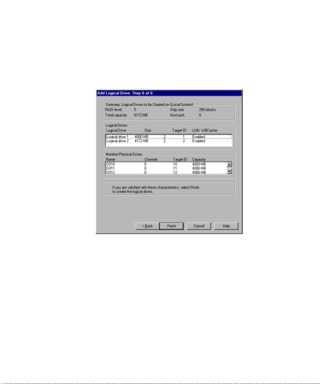
6. View a summary of the new logical drives (Figure 3-19). In this
summary you will find the RAID level, capacity, cache options, and
member physical drives that you selected for each new logical drive. If
you are not satisfied with these characteristics, you can go back and
make changes by clicking on t he Back Button. If you are sa tisfied with
the summary, click Finish.
Figure 3-19. Adding Logical Drive: Step 6
Replacing a Failed Controller
Replacing a Failed Controller in a Single
Controller Environme nt
1. Power down the shared storage array.
2. Remove the failed controller.
3. Insert the new controller.
4. Restore the configuration settings. See the section “Restoring
Configuration Setting from a File” for this procedure.
Page 56

Replacing a Failed Controller in a Redundant
Controller Environme nt
A failed controller can be replaced without powering down the shared storage
array. To replace a failed controller:
1. Remove the failed controller.
2. Insert the new controller.
Replacing a Failed Drive
A failed drive can be repla ced without powering down the share d storage
array. When a drive fails, two things can happen:
■ The logical drive associated with the failed drive utilizes a spare a nd
rebuilds the spare drive to join the logical drive. The logical drive will
be in a reconstructing state.
■ The logical drive stays in a reduced state until a new drive is a dded.
To replace the failed drive:
1. Remove the failed drive.
CR3500 Configuration Utility 3-25
2. Insert the new drive.
3. See the “Adding Physical Drives” section for procedures to make the
new drive known.
4. Set the new drive status.
If a spare drive was used to reconstruct the affected logical drive, set the
new drive as a spare drive.
If there was no spare drive to use, the logical drive is still in a reduced
state. Add the new physical drive to the logical drive and reconstruction
can start.
a. Select the logical drive in reduced status.
b. Select Logical Drive from the Storage pull down menu.
c. Select Rec onstr uct.
d. A list appears showing you available drives. Select the drive you just
added.
e. Rec onstruction begins.
Page 57

3-26 Compaq ProLiant CL1850 Software User Guide
Setting a Physical Drive as a Spare
NOTE: Spare drives serve as spares to all logical drives. They are not grouped with a
particular logical drive.
How a Spare Works
■ If a physic al drive fails in a RAID 1, RAID 0+1, RAID 4, or RAID 5
logical drive, the spare automatically replaces the failed physical drive
and the controller reconst ructs all logical drives the failed physical drive
was a member of.
■ Once the controller writes data to a spare, the spare becomes part of the
same device group in whic h a device failed.
■ Once the controller writes data to a spare, the status of the spare changes
to Good.
To Define a Spare Physical Drive
1. In the main window, click the physical drive to be used as a spare. The
physical drive must be in the Available state.
2. From the Storage menu, choose Physical Drive, then choose Make
Spare.
NOTE: The spare must have a capacity equal to or greater than the failed physical drive
for an automatic reconstruct to start.
Managing Spare Physical Drives
Making a spare physical drive part of a logical drive will protect the integrity
of the RAID setup. This proves especially true for logical drives that have
RAID requir ements of tw o or more physical drives. Should one physical drive
fail, the logical drive will automatically activate the spare physical drive as an
instant replacement for the failed one.
Managing Failed Physical Drives
To return a failed physical drive to a nonfailed state, from the Storage menu,
select Physical Drive, and then select Clear Failure.
You can easily identify a failed physical drive from the main screen because
the failed icon will appear. See Table 3-5 for the physical drive icons.
Page 58

Deleting Logical Drives
CAUTION: If you delete a logical drive, all of your data on that logical drive will
be lost. The logical drives in your storage subsystem are logical units that
contain your user data. Although they do not exist in a physical sense, it is their
logical structure that ties together the physical pieces of your data spread
across their members. Use extreme caution when deleting a logical drive.
1. Click the logical drive s that you wa nt to delete.
2. From the Storage pull-down menu, select Logical Drive, then select
Delete. A syste m message appears, asking if you want to delet e all disks
in the group.
3. Click Yes to delete all the disks in the group.
Using Configuration Files
You can use a configuration file to save the configuration settings of the
CR3500 RAID Controllers and disk drive s and view or rec onstruct the se t tings
at a later time. You also can revert to one of these saved configurations at any
time. The CR3500 Configuration Utility reads the c onfiguration file you
choose and sets up your subs yst em accordingly.
CR3500 Configuration Utility 3-27
Saving Configuration Settings to a File
From the Storage pull-down menu, select Controller, then select
Configuration, then select Save. The current configuration settings, including
caches, LUNs, host ports, and strip size will be saved.
CAUTION: When saving a configuration, all controller data and RAID set data is
preserved at the time of the Save operation. When restoring a configuration, the
configuration being restored must match EXACTLY the configuration when it
was saved. Any RAID sets in existence when the Restore Configuration operation
takes place that were not in existence when the configuration was saved will be
reinitialized, and any data on those RAID sets will be lost. Make sure you have a
recent backup copy of your configuration data before you execute this operation.
Restoring Configuration Settings from a File
You can automatically re store or configure your entire storage subsystem from
a previously saved configuration file. The CR3500 Configuration Utility can
configure your subsystem from a file only if the file corresponds t o your
subsystem’s hard w ar e conf i gur a tio n.
Page 59

3-28 Compaq ProLiant CL1850 Software User Guide
From the Storage pull-down menu, select Controller, then select
Configuration, then select Restore.
All of the configuration se ttings, including caches, LUNs, host port, and strip
size will be restored to their original condition.
CAUTION: When restoring a configuration, the configuration being restored
must match EXACTLY the configuration as it was saved. Any RAID sets in
existence when the Restore Configuration operation takes place that were not in
existence when the configuration was saved will be reinitialized, and any data
on those RAID sets will be lost.
You will not be able to restore the original configuration settings if the original
hardware and connections have been replaced or if the original configuration
settings were not saved before implementing the changes.
Updating Firmware
At some time, new firmware may be released for the CR3500 RAID
Controller. This firmware can be obtained from the Compaq website. To
update the firmware on the controller, select Update Firmware from the
Storage pull–down menu from the main screen. Enter the new firmware file
location and click Update.
IMPORTANT: Microsoft Cluster Server service, SNMP service, and any I/O must be
stopped during the firmware update.
Upgrading from a Si ngle Controller to Redundant Controllers
To upgrade your system from a single CR3500 RAID Controller to a
redundant CR3500 RAID Controller co nfiguration, follow these steps.
1. Save the existing single controller configuration using the Save
Configuration function.
2. Suspend all I/O and power down the shared storage subsystem.
Page 60

3. Install the redundant controller in the bottom c ontroller slot of the
shared storage subsystem.
4. Power up the shared storage subsystem.
5. Restore the controller configuration settings that you saved in Step 1.
NOTE: If restoring configuration settings using a serial connection, both controllers must
be attached to the host machine.
Error and Warnin g Messages
When you start the CR3500 Configuratio n Utility, the software checks each
controller to detect errors in its configuration. I f a problem is f ound, the
CR3500 Configuration Utility displays an error warning message that
describes the problem.
IMPORTANT: If a warning message indicates “Internal Error Has Been Detected” and
cites an error code number, the problem requires assistance from Compaq technical
support. See the “About This Guide” section at the beginning of this book for technical
support phone numbers.
CR3500 Configuration Utility 3-29
Refer to the Online Help for more information.
Page 61

Chapter 4
Integrated Management Log
NOTE: The Compaq Integrated Management Log (IML) only records events for the server
nodes. The IML does not record events in the shared storage array.
The Compaq Integrated Management Log (IML) records events and stores
them in an easily viewable form. The Compaq Integrated Management Log
records hundreds of events and then marks each event with a time-stamp with
one-minute granularit y.
Events listed in the Compaq Integrated Management Log are categorized as
one of four e vent severity levels:
■ Status–indicates that the message is informational only.
■ Repaired–indicates that corrective action has been taken.
■ Caution–indicates a nonfatal error condition.
■ Critical–indicates a component failure.
The Compaq Integrated Management Log requires Compaq Operating
System-dependent drivers. Refer to the Compaq SmartStart and Support
Software CD f or instructions on installing the appropriate drivers.
Page 62

4-2 Compaq ProLiant CL1850 Software User Guide
Multiple Ways of Viewing the Log
You can view an event in the Compaq Integrated Management Log two ways:
■ From withi n Compaq Insight Manager
■ From within Compaq Survey Utility
Compaq Insight Manager
Compaq Insi ght Manager is a server management tool providing in-depth
fault, configuration, and performance monitoring of hundreds of Compaq
servers from a single manage ment console. The system parameters that are
monitored describe the status of all key server node com ponents.
By being able to view the e vents that occur, you can take immediate action.
You can view and print the e vent list from within Compaq Insight Manager by
following the instructions below. You can also mark a critical or caution event
as repaired after the affected component has been replaced, for example, if a
fan that has fa iled has been replaced. Y ou can lower the severity of the event
by marking it as repaired.
Viewing the Event Li st
1. From Compaq Insight Manager, select the appropriate server node; the n
select View Device Data.
The selected se rver node is displayed wit h buttons around its perimeter .
2. Select the Recovery button.
3. Select Compaq Integrated Managemen t Log.
NOTE: You can only view the list from the Recovery/Integrated Management screen. To
print the list, follow the instructions in the following section.
4. If a failed component has been replaced, select the event from the list
and then select Mark Repaired.
Page 63

Printing the Event List
NOTE: You can only view the list from the Recovery/Integrated Management Log screen
as described above. To print the list, follow the instructions below.
1. From Compaq Insight Manager, select the appropriate server node. The
selected server node displays with buttons around its perimeter.
2. Click the Configuration button.
3. Click the Recovery button.
4. Click Print.
Compaq Survey Utility
The Compaq Survey Utility is a serviceability tool available for Microsoft
Windows NT and Novell NetWare that delivers online configuration capture
and comparison to maximize server node availability. It is deli vered on the
Compaq Management CD in the Cluster Set up and Management pack, or is
available on the Compaq website. Refer to the Compaq Management CD for
information on installing and running the Survey Utility.
Integrated Management Log 4-3
After you have run the Survey Utility, you can view the Compaq Integrated
Management Log by loading the output of the utility (typically called
SURVEY.TXT) into a text viewer such as Microsoft Notepad. The event list
follows the system slot inf ormation. Once you have opened the text file, you
can print it using the print feature of the viewer.
Page 64

4-4 Compaq ProLiant CL1850 Software User Guide
List of Events
The event list displays the affected components and the associated error
messages. Although the same basic informat ion is displayed, the format of the
list may be different de pending on how you are view ing it from within
Compaq Insight Manager or the Compaq Survey Utility.
The following table identifies the event types (affected components) and
associated event messages.
Event Type Event Message
Machine Environment
Fan Failure
Fans Not Redundant
Overheat Condition
Main Memory
Correctable Error Threshold
exceeded
Uncorrectable Error Uncorrectable Memory Error (Slot X, Memory Module X)
Processor
Correctable Error Threshold
exceeded
Uncorrectable Error
Host Bus Error
PCI Bus Error PCI Bus Error (Slot X, Bus X, Device X, Function X)
POST Error POST Error: Error message
Table 4-1
Event Messages
System Fan Failure (Fan X, Location)
System Fans Not Redundant
System Overheating (Zone X, Location)
Corrected Memory Error threshold passed (Slot X, Memory Module X)
Corrected Memory Error threshold passed (System Memory)
Corrected Memory Error threshold passed (Memory Module unknown)
Uncorrectable Memory Error (System Memory)
Uncorrectable Memory Error (Module unknown)
Processor Correctable Error Threshold passed (Slot X, Socket X)
Processor Uncorrectable internal error (Slot X, Socket X)
Unrecoverable Host Bus Data Parity Error
Unrecoverable Host Bus Address Parity Error
continued
Page 65

Table 4-1
Event Messages
Power Subsystem
Power Supply Failure
Power Supply Inserted
Power Supply Removed
Power Supply Not Redundant
System Configuration
Battery Low
Power Module Failure
AC Voltage Problem
Power AC Overload
Automatic Server Recovery
System Lockup ASR Lockup Detected: Cause
Operating System
System Crash
Automatic OS Shutdown
continued
Event Type Event Message
System Power Supply Failure (Power Supply X)
System Power Supply Inserted (Power Supply X)
System Power Supply Removed (Power Supply X)
System Power Supplies Not Redundant
Real-Time Clock Battery Failing
A CPU Power Module (System Board, Socket X)
A CPU Power Module (Slot X, Socket X)
System AC Power Problem (Power Supply X)
System AC Power Overload (Power Supply X)
Blue Screen Trap: Cause [NT]
Kernel Panic: Cause [UNIX]
Abnormal Program Termination: Cause [NetWare]
Automatic Operating System Shutdown Initiated Due to Fan Failure
Automatic Operating System Shutdown Initiated Due to Overheat
Condition
Fatal Exception (Number X, Cause)
Integrated Management Log 4-5
Page 66

Chapter 5
System Management for Microsoft
Windows NT Server 4.0,
Enterprise Edition
Throughout the life of your Compaq ProLiant CL1850 you will encounter the
need to improve performance, upgrade hardware components, upgrade
software, increase storage capacity, restructure cluster groups, back up cluster
data, or merely monitor ongoing activities. This chapter describes these
management c oncepts as the y pertain to Microsoft Cluster Server (MSCS)
clusters. The chapter also details the utilities and programs used in the ongoing
management of your system. The topics addressed in this chapter include:
■ Cluster M anagement Concepts
■ Compaq I nsight Manager
■ Microsoft Cluster Administrator
■ Modifying Physical Cluster Resources
■ Backing Up Your Cluster
■ Managing Cluster Performance
Page 67

5-2 Compaq ProLiant CL1850 Software User Guide
Cluster Managemen t Conc ep ts Usi ng Microsoft Windows NT
Managing a Cluster without Interrupting Applications or Services
At some time during the life of your system, it is likely you will need t o
perform an operation on a server node that will require it to be powered down.
Always use Cluster Administrator to fail over (or at a minimum, bring offline)
clustered applications be fore powering down the ser ver.
Managing a Cluster in a Degraded Condition
Due to the high-availability nature of clustering, applications and network
clients remain operational even while some cluster components do not. When
the cluster is in this degraded condition, it is important to follo w thi s process:
1. Understand what caused the degrada tion.
2. Determine whether the condition will continually worsen.
3. Determine how critical it is to repair the problem.
a. If the problem is c onsidered noncritical, wait until a nonpeak time to
service the problem.
b. If the problem is considered critical, fail over all clustered
applications and resources to the other server node before servicing
the problem.
Managing Hardware Components of Individual Server Nodes
Compaq Insight Manager has been enhanc ed to operate with the Compaq
ProLiant CL1850. While Compaq Insig ht Mana ger maintains its current
features of viewing and managing servers and their components, it now allows
you to view tw o server nodes a s a single cluste r entity. A comprehensive
overview of Compaq Insight Manager’s cluster capabilities appears later in
this chapter.
Page 68

System Management for Microsoft Windows NT Server 4.0, Enterprise Edition 5-3
Managing Network Clients Connected to a Cluster
An important aspect of managing network clients is to inform the users that
their applications are now running on a cluster. Since users will experience
some disruption of service, and possibly a performance degradation during
failover, they might become concerned about the availability and stability of
their applications. As the cluster is initially brought into a production
environment, it might be beneficial to describe in a memorandum t he effects a
cluster will have o n the users’ information systems needs.
When a failover or failback event occurs, the users’ perspective will be only
that they cannot access their application or data. When users have been
properly forewarned of the effects of operating in a clustered environment,
they will more readily recognize when a failover or failback event is occurring
or has occurred. Most will wait several minutes before tr ying to reconnect to
their application or data.
Managing a Cluster’s Shared Storage
Compaq Insight Manager monitors the cluster. The physical drives and
hardware are monitored via the Mass Storage Overview screen, accessed from
the Device View screen.
The shared logical drives (as well as other cluster resources and services) are
monitored via the Cluster Management a nd Cluster Shar ed Resources screens,
accessed from a cluster folder in the Device List.
Because this storage system is shared, either server node could be the owner of
any shared logical drive. While only one server node can own the logical drive
at any given time, ownership can switc h from one server node to another.
Compaq Insight Manager reports the curr ent owner of a l ogical drive and
updates this information dynamicall y if a failover occurs.
NOTE: Compaq Insight Manager shows the shared logical drives as cluster resources
owned by a particular server node. It shows the cluster hardware as a physical resource
of both servers in the cluster.
When viewing the Compaq I nsight Manager Cluster Shared Resources scr een,
you can determine which logical drive contains a particular dr ive by looking at
the Physical ID field under the Shared Resources heading.
Page 69

5-4 Compaq ProLiant CL1850 Software User Guide
Remotely Managing a Cluster
Both Compaq Insight Manager and Microsoft Cluster Administrator can be
run from net work client machines. Each program al lows monitoring of
multiple clusters from a single remote client. See the corresponding
documentation to determine how to set up and configure each of these
programs to run remotely.
Cluster Events
Cluster events are logged in the Windows NT Event Log. Use the
Windows NT Event Viewer to view the data in the Event Log.
Compaq Insight Mana ger
Compaq Insi ght Manager is the Compaq a pplication for easily managing
network devices. Compaq Insight Manager delivers intelligent monitoring and
alerting as well as visual control of your networked systems. Compaq Insight
Manager 4.50 or greater has been updated to recogn i ze and monit or the
Compaq ProLiant CL1850. T he following is an overview of the clusterspecific features found in Compaq Insight Manager.
NOTE: The term cluster group used in this section refers to Compaq Insight Manager, not
to Microsoft Cluster Server.
Page 70
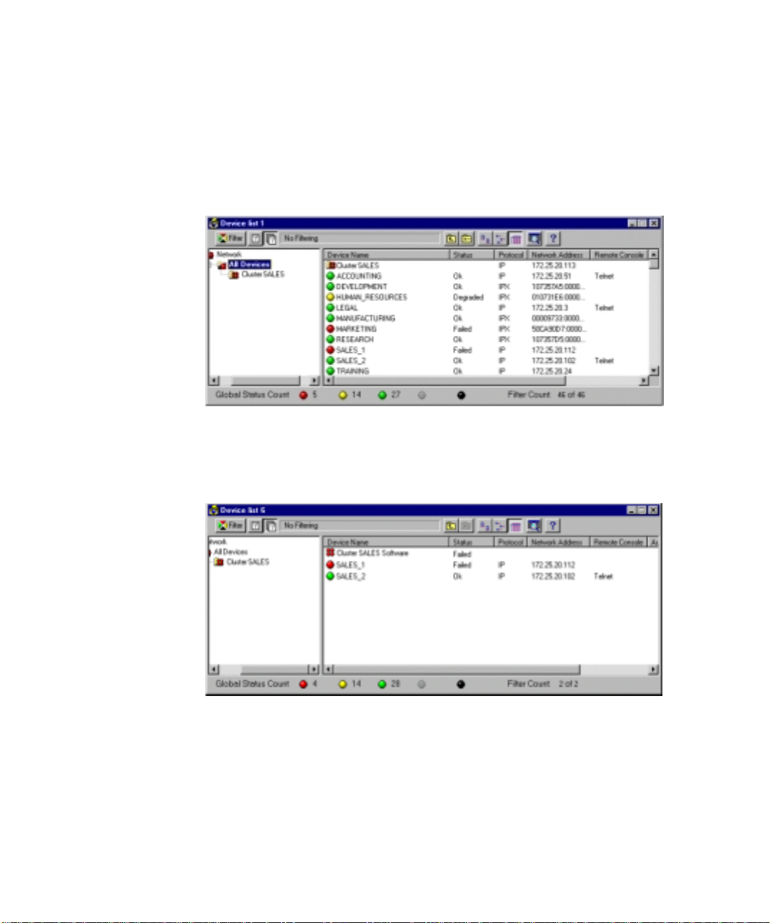
System Management for Microsoft Windows NT Server 4.0, Enterprise Edition 5-5
Explorer Device List Screen
When Compaq Insight Mana ger discovers a c luster, a clust er group is
automatically created and added to the Group window of Insight Manager’s
Explorer Device List screen (Figure 5-1) . The cluster protocol an d address are
also displaye d.
Figure 5-1. Insight Manager Explorer Device list screen
When the clus t er group is sel ected in the Gr oup window, the two server nodes
and a generic Cluster Software item are listed in the Device window of Insight
Manager’s E xplorer Device List screen (Figure 5-2).
Figure 5-2. Explorer Device list screen, Cluster Group selected
Page 71
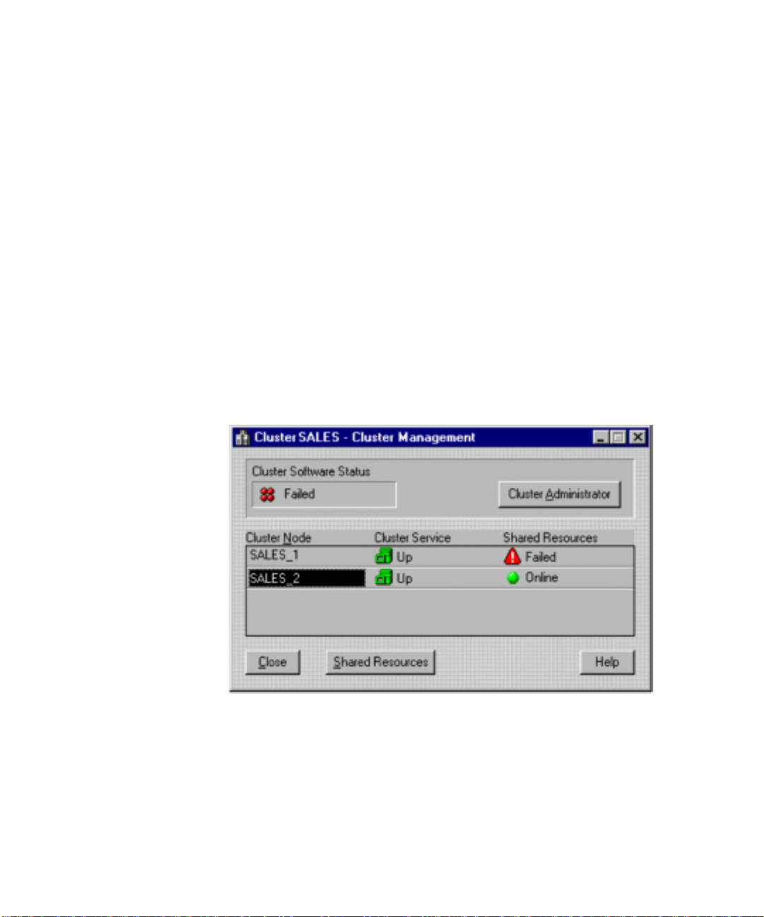
5-6 Compaq ProLiant CL1850 Software User Guide
Cluster Management Screen
Compaq Insight Manager inc ludes a Cluster Management sc reen. From the
Cluster Management screen you can:
■ Launch Microsoft Cluster Administrator
■ Bring up t he Compaq Insight Manager Clust er Shared Resources screen
■ View the status of the cluster service running on each server node
■ View the overall status of all cluster resources. This information is
updated dy namically.
You can launch the Cluster Management screen (Figure 5-3) by using any of
the following methods:
■ Select from the Task List or right-mouse menu of a clustered device.
■ Select from the right-mouse menu of the Cluster Software item.
■ Double-c l ick on the Cluster Software item.
Figure 5-3. Cluster Management screen
If Microsoft Cluster Administrator is installed on t he Compaq I nsight Manager
console, you can launch Cluster Admini st rator by clicking on the Cl uster
Administrator button near the upper-right corner of the screen, or by selecting
an option from the right-mouse menu of the Cluster Software item. Cluster
Administrator will launch directly to the cluster represented by the Cluster
Management screen.
Page 72
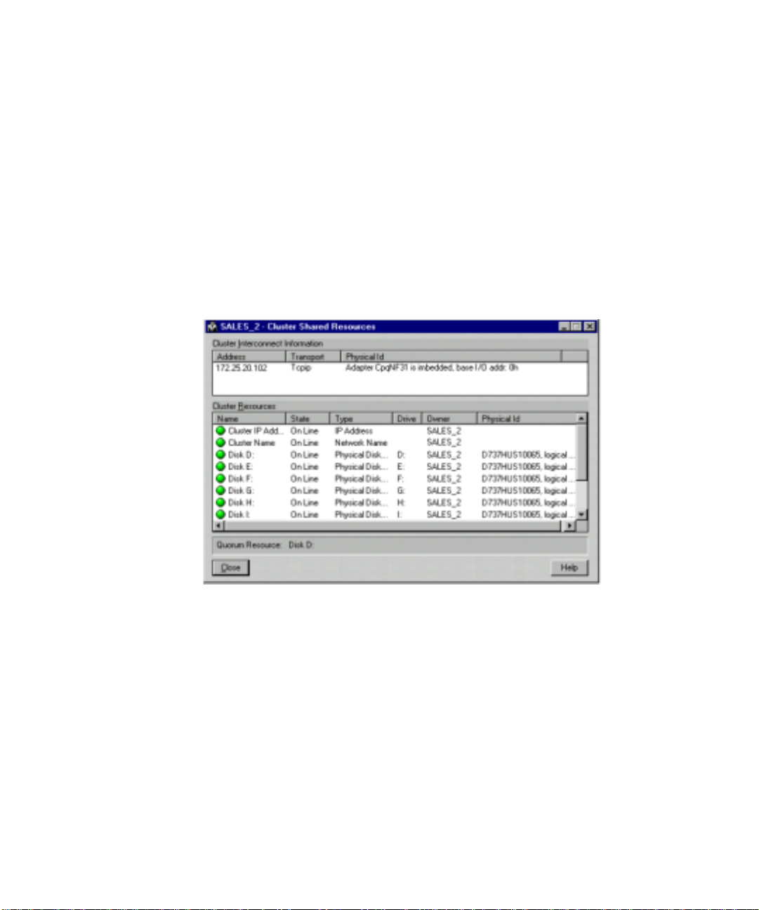
System Management for Microsoft Windows NT Server 4.0, Enterprise Edition 5-7
Cluster Shared Resources Screen
The Cluster Shared Resources screen (Figure 5-4) contains specific
information about the cluster interconnect and all cluster resources r unning on
the server node.
From the Compaq Insight Mana ger Cluster Shared Resources screen you can:
■ View address, transpor t protocol, and physical ID of all cluster
interconnects
■ View the current state of all cluster resources
■ Sort the interconnect information and resources by multiple criteria
Figure 5-4. Cluster Shared Resources screen
All displayed interconnect and resource informat ion is polled and updated
dynamically, includin g status and ow nership.
For example, assume two drive volumes are defined in your shared storage.
The primary owner of the drive volume labeled E: is server node 1. The
primary owner of the drive volume label ed F: is server node 2. When the
cluster is in a normal state, Insight Manager will show E: as being owned by
server node 1, and F: as being owned by serve r node 2. Whe n a failover e vent
occurs, ownership of the drives change s. Assume server node 1 exper iences a
failure and its resources fail over to server node 2. When the failover is
complete and Insight Ma nager polls the cluster, server node 2 wil l be
identified as the owner of both F: and E:.
Page 73
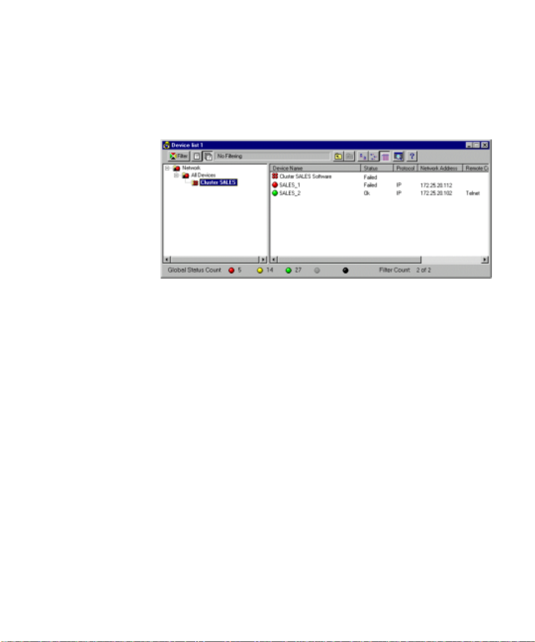
5-8 Compaq ProLiant CL1850 Software User Guide
Cluster Group Hierarchy
You can manage cluster groups at an appropriate level in the group hierarchy.
Cluster groups are always displayed at the All Devices level (Figur e 5-5), but
cluster gro up shortcuts can be added to other groups.
Figure 5-5. Sample group hierarchy
Page 74

System Management for Microsoft Windows NT Server 4.0, Enterprise Edition 5-9
Filter Groups Dialog Box
The Filter Groups dialog box (Figure 5-6) is used to create, edit, or delete
groups in the group list hie rarchy.
Follow these steps to launch the Filter Groups dialog:
1. From the Group window in the Device List w indow, selec t the group
you want to w ork with. (For example, if you want to create a group
within Network, select Network.)
2. Select the Set Up Group button on the control bar.
Figure 5-6. Filter Groups dialog box
The Insert cluster shortcut button allows you to create shortcuts for existing
cluster groups and place them in different levels in the group hierarchy.
Cluster Address
A cluster address acts as a proxy, communicating with dif ferent servers i n the
cluster depending on the state of the cluster. A Compaq Insight Manager
device using a cluster address may switch communication from one physical
device to another, which m ay result in er roneous inf ormation being delivered.
Consequentl y, Compaq Insight Manager does not allow management of a
device that uses a known clust er address.
Page 75

5-10 Compaq ProLiant CL1850 Software User Guide
Microsoft Cluster Administrato r
While the pri mary responsibility of Compaq Insight Manager is t o monitor the
overall status of the cluster hardware, services, and resources, Microsoft’s
Cluster Administrator is most adept at managing the groups, resources, and
operating state of the cluster. Cluster Administrator gives you the ability to:
■ View the current statu s of cluster groups and resources
■ Bring gr oups and resources online and offline
■ Manually move groups and resources to another server node
■ Manually move groups and resources to their pre ferred server
■ Pause groups and resour ces
■ Restructure a group’s resource dependency tree
Cluster Administrator can be run remotely or on a server node. If Cluster
Administrator is installed remotely, the remote node must be in the same
domain as the server node. When running Cluster Administrator rem ot ely, you
should connect to the cluster via Compaq Insight Mana ger or by using the
cluster IP address or cluster name.
NOTE: The remote feature is not supported in Microsoft Windows 95/98.
Refer to the Microsoft Cluster Server Administrator’ s Guide for a thor ough
description of Cluster Adm inistrator’s features and specifics on how to use the
utility.
Modifying Physical Cluster Resources
Removing Shared Storage
Each server node, and the cluster as a whole, depends on the shared storage for
data, log, and, possibly, application program files. If the shared storage is
removed, all clustered applications that are dependent on that shared storage
system will be offline. Clearly, network clients will not have access to the
clustered applications.
Before removing a shared storage system (that is, the cluster), use Cluster
Administrator to bring of fline all cluster groups and r esources on b oth server
nodes. This ensures the groups and resources are gracefully brought offline,
rather than c ausing an abr upt interrupti on of service b y powering down the
cluster.
Page 76

System Management for Microsoft Windows NT Server 4.0, Enterprise Edition 5-11
Adding Shared Storage
A ProLiant st orage system ca nnot be added while the cluster is running.
Follow these steps to add another shared storage system to an existing cluster.
1. Use Microsoft Cluster A dministrator to bring all c l uster groups and
resources offline.
2. When installing the new storage system, you do not wa nt the cluster
service to start automatically. On each server node, go into the
Windows NT Services Control Panel applet and set the cluster service to
Manual.
3. Shut down and power off both server nodes and the shar ed storage
array.
4. Plug all of the SCSI drives into the shared storage array.
5. Power up the newly added storage system and the CL1850 shared
storage array.
6. Power up server node 1 and run the CR3500 Configuration Utility. Set
up the logical drives.
IMPORTANT: Be sure you understand your cluster groupings of applications and
resources whose data, log, and program files may reside on these drives. See Chapter 4
for information on creating cluster group.
7. Run Disk Administrator to a ssign permanent letters to the drive
volumes.
8. Shut down the server node 1.
9. Power up the server node 2.
IMPORTANT: Do not run the CR3500 Configuration Utility on the second server node. The
information entered from the first server node is maintained on the drives; therefore, the
drives are already configured for the second server node.
10. Boot Wind ows NT on server node 2, then run Disk Administrator.
Verify that the drive letters displayed are the same as those assigned
from the first server node.
11. Power on server node 1 and allow it to boot into Windows NT. Go into
the Service Control Panel applet and start the cluster service. Start
Cluster Administrator and verify that the added dri ves are visible as
unassigned physical disk resources.
Page 77

5-12 Compaq ProLiant CL1850 Software User Guide
12. On server node 2, go into the Service Control Panel applet and start the
cluster service. Start Cluster Administrator and verify that the added
drives are visible as unassigned physical disk resources.
13. On the server node 1, create the groups or resources that use the new
physical disk resources.
14. Ensure that all applications and resources are still offline on both ser ver
nodes. If not, take them offl ine.
15. On each server node, go into the Service Control Panel applet and set
the cluster service to start automatically.
16. Shut down and power down both server nodes.
17. Wait several seconds, then power up both se rver nodes. Windows NT
will start, followed by the execution of Cluster Server.
18. Run Cluster Administr ator and verify that the original groups and
resources are in their expected states. Then verify that the added groups
and resources are in their expected states.
Adding or Removing Shared Storage Drives
There are two situations in which you w ould add or remove drives from the
shared storage:
■ When one of the drives fails. In this case, you are simply exchanging the
failed drive for a new one.
■ When you want to add ca pacity to your cluster.
In both situations, it is assumed you ar e employing RAID 1, 0+1, 4, or 5 for all
the devices in the storage unit.
Replacing a Failed Drive
The procedure for replacing a failed drive is completed within the storage area.
Neither Cluster Server nor Windows NT is aware of the change, and operation
of both continues without interrupti on.
IMPORTANT: If the failed drive was not configured to use RAID 1, 0+1, 4, or 5 (that is,
your drives have no fault tolerance), you may lose some or all of the data on the failed
drive.
See Chapter 3, “CR3500 Configuration Utility,” for instructions on replacing a
failed drive.
Page 78

System Management for Microsoft Windows NT Server 4.0, Enterprise Edition 5-13
Adding a Drive to Increase Storage Capacity
It is foreseeable that during the life of your ProLiant CL1850 you will need to
expand the capacity of your storage system. The following steps describe how
to add a drive to the system and to allocate it to Cluster Server.
NOTE: You cannot increase the capacity of an existing logical drive in the shared storage
array.
1. Physically add the drives to the system.
2. Run the CR3500 Configuration Utili ty to configure the drives.
3. Run Windows NT Disk Administrator from server node 1 to assign a
drive letter to the newly created RAID volume.
4. While still running Disk Administr a tor, format the drives using NTFS.
5. Cluster Server requires a reboot of each server node following the
addition of a drive. Shut down both servers and reboot them.
6. Followin g the reboot, start Cluster A dministrator and verify all newly
added drive volumes appear to the cluster as available disk resources.
Page 79

5-14 Compaq ProLiant CL1850 Software User Guide
Backing Up Your Cluster
The need for c l uster backup is essential for both business-critical and nonbusiness-critical data. As data becomes an increasingly valued company asset,
it needs to be backed up on a re gular basis. The process of backing up data
will ensure that a company’s assets are secure and available when a disaster
strikes. The cluster itself provides a hi gh degree of application a vailability but
does not prevent a user from deleting or corrupting a f ile or set of files.
Backing up a cluster’s data will increase the overall level of data availability.
Compaq currently suggests the use of one of the following solutions:
■ The first solution uses two tape backup subsystems, one tape backup
subsystem atta ched to each server node.
■ The second solution shares a SCSI tape backup subsystem between the
two server nodes.
Each solution has its limitations from both the hard ware and software
perspective. The limitations are due to the fact that tape backup software for
use with Windows NT has not be en updated for clustering. As Windows NT
clustering becomes more prevalent, tape backup vendors will update their
software to become cluster-aware.
The lack of cluster-aware tape backup software presents the user with two
problems:
■ First, there may be an inability to locate files when the cluster is in a
degraded state. For example, assume server node 1 owns a shared drive,
G:. A tape backup is performed from ser ver node 1 an d drive G: is
backed up. At some point in the future, a need arises to restore some
files to drive G:. However, drive G: is in a failover state and is currently
owned by server node 2. An a ttempted restoration of the files from
server node 1 may fail if the tape backup software is unable to
comprehend the shared characteristic of drive G:.
■ Second, if a failover or failback eve nt occurs whi l e a backup is
executing, you may not be able to conti nue the backup; you may be
required to restart the backup from the beginning. For example, if you
are backing up drive G: from server node 1 and a failover event moves
drive G: to server node 2, the backup process will abort since drive G: is
no longer accessible from server node 1. The backup process, if
configured a s a cluster group and if the backup software supports a
restart, can possibly be automatically restarted on server node 2. Still,
the restarted backup will start at the beginning; the data placed on tape
by the interr upted backup process on server node 1 is lost.
Page 80

System Management for Microsoft Windows NT Server 4.0, Enterprise Edition 5-15
Managing Cluster Performance
As applications or resources transfer from one server to another, the
performance of the clustered servers will likely change. The extent of the
performance change depends greatly on how well equipped the other server
node is to handle the increase in workload. This is especially obvious after a
server failure, where all of the cluster resources may move to the other server.
You can use the Windows NT Performance Monitor to observe and track
system performance. Some applications may also have their own internal
performance measurement capabilities. Constant monitoring of each system’s
performance in a cluster may identify a disparity in the workload being
performed by e ach server. Adjust the distribution of the cluster applications so
that the overall cluster performance is maximized.
Dynamic load balancin g is not availa ble in the initial release of Microsoft ’s
Cluster Server. However, Cluster Server does offer the ability to manually
load balance your server nodes. You can use information obtained from
Performance Monitor to determine whether either of the server nodes is
operating at too high a performance level. Use Cluster Administrator to fail
over as many cluster groups as necessary to balance the load of each server
node.
The timing of manually m oving a cluster group to balance the load should
depend strongly on what type of group needs to be moved and how many
clients are using the grou p. File and print services are nor mally not
business-critical, nor do they sustain an extremely high utilization rate. For
these reasons, file and print services are good candidates to move whenever
load balancing needs to occur, even when the overall cluster utilization is high.
However, some applicati ons, such as databases, should not be moved f rom one
server to ano t her during peak processing periods. When a database i s moved
from one serve r to another, the database must be shut down and restarted.
During the time it takes the database to restart, users do not have access to the
database. In these cases, moving a database group to another server should be
performed during nonpeak hours.
Page 81

Index
A
access panel labels vii
active/active 3-14, 3-16
active/passive 3-14, 3-16
add logical drive wizard 3-1
administrative tools 1-8, 1-9
applications
configuring 1-11
installing 1-11
setting up 1-11
arrays 3-1
mirrored 3-1
single device 3-1
striped 3-1
mirrored 3-1
parity 3-1
assisted integration path 1-2, 1-4,
1-6, 2-2, 2-4
B
boards, add-on xi
bus width 3-16
buttons
add logical drive 3-8
configuration 4-3
CR3500 Configuration
Utility 3-7
details 3-8
help 1-3, 1-4, 1-6, 1-7, 2-2,
2-4
accessing 1-2, 1-4
large icons 3-8
list 3-8
recovery 4-3
small icons 3-8
C
cables, network 2-7
cache 3-27, 3-28
limit 3-14
memory size 3-18
options 3-24
tab 3-13
writeback 3-23
capacity 3-24
adding 3-21
cards
network 2-7
SCSI ID 1-4, 1-6, 1-7
cautions
configurations
restoring 3-2 8
saving 3-27
logical drives 3-27
CDs
Compaq SmartStart 2-1
Management vii
Page 82

2 Compaq ProLiant CL1850 Software User Guide
Microsoft Windows NT
Enterprise Edition 1-3, 1-5
SmartStart 1-1, 1-2
SmartStart and Support
Software vii
Systems Reference Library vii
cluster
capabilities 1-11
configuring 2-5
creating 1-8, 2-8, 2-9
documentat ion 1-11
group
bringing o nline 1-11
configuring 1-11
setting up 1-11
interacting with 1-10
IP address 1-10
name 1-8, 2- 8
object 2-8
partition 2-9
pausing 2-5
resources 1-11
configuring 1-11, 2-9
creating 2-9
testing 2-7
verifying 1-8, 2-7
Cluster Administrator See
Microsoft, Cluster
Administrator
commands viii
accessing 3-6
Compaq
authorized reseller xi
telephone numbers xi
Insight Agents 1-3, 1-5
Insight Manager 1-1
installation poster 1-1
Integration TechNotes 1-11
service hours x
SmartStart 1- 1, 1-4, 2-1
installation poster 1-1
manual installation 1-5
Survey Utility 4-3
System Tools 3- 3, 3-4
System Tools Folder 1-7
Technical Phone Support
Center x
website x, xi , 1-12, 3-28
configuration
logical drive 3-2
Novell NetWare 2-1
procedure s 3-2, 3-13
reconstructing 3-27
restoring 3-2 9
saving 3-27, 3-28
server node 1-4
settings
caches 3-27
host ports 3-27
LUNs 3-27
restoring 3-2 7
saving 3-27
strip size 3-27
system 1-2
using files 3-27
viewing 3-27
connection
checking 1-10
CTRL-1 3-4
CTRL-2 3-4
network 3-15
online 3-3
SCSI 3-15
serial 3-5, 3-15, 3-29
status 2-7
console, HA Server 2-7
controllers
active 3-14
adding 3-13
configurat i on settings 3- 27
configuring 1-3, 1-7, 3-1, 3-13
dual 3-5
errors 3-29
failed, repl acing 3-24
icons 3-12
memory 3-18
mode 3-14
modifying properties 3-13
operationa l 3-12
optional 3-2
reconfiguring 3-1
Page 83

Index 3
redundant 3-2, 3-13
installing 3-29
serial connection 3-3
serial number 3-15
setting up 2-3 , 2-4
shared storage 1-6
single 3-14
status 3-12
unavailable 3-14
Wide Ultra2 S CSI 1-2, 1-4,
1-6, 1-8, 2-3, 2- 4
writing data 3-26
CR3500 Configuration Utility 1-3,
1-5, 1-7, 2-3, 2- 4, 3- 1
features 3-2
installing 1-6, 3-3, 3-4
running 3-3, 3-4
warning messages 3-29
create rate 3-15
D
desktop 1-8
DHCP 1-10
Disk Administrator 1-3
documentation
cluster 1-11
Microsoft Cl uster Server
Administrator 1-3, 1-7
MSCS 1-5
operating system 1-1, 2-1
technical 1-12
drivers 1-3, 1-5, 1-7, 1-8
information on xi
drives
adding 3-18
assigning letters 1-3
configurat i on settings 3- 27
failed 3-9
managing 3-26
replacing 3-25
good 3-9
initializing 3-10
logical 1-3, 1-7, 2- 3, 2- 4, 3- 8
adding 3-19
creating 3-1
defined 3-1
deleting 3-27
locating members 3-10
property sheets 3-10
RAID 0+1 3-26
RAID 1 3-26
RAID 4 3-26
RAID 5 3-26
window 3-10
parity
fixed 3-1
floating 3-1
physical 3-10
adding 3-18
information 3-11
setting as spar e 3-26
target ID 3-19
quorum 1-3
reconstructing 3-10
reduced 3-1 0
selecting 2-9
shared stora ge 1-3, 1-5, 1-10
spare 3-25
defining 3-26
managing 3-26
E
environments
cluster 1-11
controller properties 3-18
machine 4-4
redundant 3-25
single controller 3-24
tab 3-17
Error Log 1-3, 1-4
error messages x
errors
correctable 4-4
host bus
address pari ty 4-4
data parity 4-4
Page 84

4 Compaq ProLiant CL1850 Software User Guide
PCI bus 4-4
uncorrecta ble 4-4
unrecoverable 4-4
event
messages
associated 4-4
log 4-4
table 4-4
severity levels
caution 4-1
critical 4-1
repaired 4-1
status 4-1
type 4-4, 4-5
event list
IML 4-4
printing 4-3
viewing 4-2
F
failback
automatic 2-5
manual 2-5
failover 1-9 , 2-8
automatic 2-5
Lotus Domino Server 1-12
manual 1-10, 2-5
mode 3-14, 3-16
resource 1-12
using Oracle 1-12
FailSafe, Oracle 1-12
failure, clearing 3-26
fans, monit oring 3-17
fault tolerance 2-9
determining 3-2
method 3-2
features
configuration utility
main window 3-6
online conne ction 3-3
serial cable connection 3-3
SmartStart CD 3-3
file names viii
files, confi guration 3-27
firmware
updating 3-28
firmware revision 3-15
Flash ROM xi
G
getting help x
graphical user interface 3-1
groups
deleting members 3-27
device 3-26
predefined 1-9
H
HA Server 2-5, 2-7. See also
Novell, High Availability Server
documentat ion 2-8
failover 2-8
hardware
add-on xi
cluster 1-11
configuration 3-27
configurat i on and installation
poster 1-1, 2-1
configuring 1-2, 1-4, 1-6, 1-7
installing 1-2, 2-2
modificati on 1-2, 1-4, 1-6
modifying 1-8
review 1-2, 1-4, 1-6, 1-8
settings 1-2, 2-2, 2-4
third-party xi
help
additional sources x
Compaq
authorized resellers xi
website xi
menu 3-7
online 1-2, 1-3, 1-4, 1- 6, 1-7,
2-2, 2-4, 3-2, 3- 7, 3- 1 7,
3-29
technical support x
telephone numbers x
toolbar 3-2
high availability 3-14, 3-16
Page 85

Index 5
high perfor mance 3-14
http://www.compaq.com x, xi, 1-12
I
I/O
activity 3-14
channel mode 3-16
host 3-16
response 3-14
icons
add logical drive 3-8
controllers 3-12
detail button 3-8
failed drive 3-26
JBOD 3-9
large 3-8
list button 3-8
logical drive 3-10
logical drive state 3-9, 3-10
physical drive 3-10, 3-26
RAID 0 3-9
RAID 0+1 3-9
RAID 1 3-9
RAID 4 3-9
RAID 5 3-9
small 3-8
status 3-12
symbols on e quipment ix
tool bar 3-8
using 3-7
warning 3-17
IIS 1-11
IMD 4-2
IML
defined 4-1
event list 4-4
printing from Insight
Manager 4-2
requireme nt s 4-1
severity le vels 4-1
viewing
from Insight M anager 4-2
log 4-2
using Survey Utility 4-3
information
capacity 3-10
name 3-10
RAID level 3-10
setup 1-11
sources 1-11
state 3-10
storing 1-3
technical vii
installation
final screen 2-9
HA Server 2-5
hardware 2-2
manual 1-5
Novell Cluster Services 2-8
operating s ystem 2-2
overview 2-2
poster 2-1
software 2-2
Integrated Management
Display See IMD
Integrated Management Log See
IML
IP addresses 1- 8, 1-9, 1-10, 2-9
J
JBOD 3-1
K
KVM switch 1-4, 1-7, 2-3
L
labels, access panel vii
languages, selecting 1-2
logical drives 1-7
adding 3-19, 3-25
capacity 3-21
attributes 3-10
creating 3-1, 3-18
defined 3-1
deleting 3-27
display 3-8
icons 3-8, 3-9
Page 86

6 Compaq ProLiant CL1850 Software User Guide
increasing capacity 3-18
locating members 3-10
name 3-10
reconstructing 3-25
reduced state 3-25
setting up 2-3 , 2-4
state 3-10
status 3-9
storage available 3-20
strip size 3-22
types 3-9
window 3-9, 3-10
wizard 3-1
Logical Unit Number See LUN
Lotus Domino Server 1-12
LUN 3-23, 3-27, 3-28
M
management
CD vii
Insight Manager 4-2
tool 4-2
manual configuration 1-6
manual configuration path 1-7
manual installation 1-5, 1-6
memory
cache 3-18
main 4-4
size 3-18
menu bar 3-7
menus
accessing 3-6
file 3-7
help 3-7
shortcut 3-7
storage 3-7, 3-26
view 3-7
messages
error 3-2, 3-29
warning 3-2, 3-29
Microsoft
Cluster Administrator 1-8,
1-9, 1-10
Cluster Server 3-28
Administrator 1-3, 1-5
administrator’s guide 1-1, 1-11
Disk Administrator 1-3, 1-7
Enterprise Edition
Installer 1-3 , 1-5, 1-7
file service 1-11
Internet Information
Server 1-11
Notepad 4-3
NTFS 1-3, 1-7
print service 1-11
resource failover using
MSCS 1-12
service failover 1-11
using MSCS 1- 11
SQL Server 1-12
Windows NT
administrator’s guide 1-1
configuration 1-1
Explorer 3-3
installation 1-3
logging in 1-3
system setup 1-1
MSCS 1-1, 1-7
administrator 1-3, 1-5, 1-7
Internet Information
Server 1-11
N
names
cluster 1-9
directory viii
drive viii
server node 1-9
NCS See Novell, Cluster Services
Page 87

Index 7
network
cable 2-8
card 2-7
client
failover 1-1 0
connection type
SCSI 3-15
serial 3-15
machine 1-10
nodes See server nodes
Novell
Cluster Services 2-8, 2-9
documentat ion 2-5
High Availability Server 2-1
NetWare
4.2 2-1, 2-5
5 2-1
configuration 2-1
link discon nect 2-7
setup 2-1
testing 2-7
volumes 2-9
NTFS 1-3
O
online conne ction 3-3
operating s ystem 3-14
documentat ion 1-1, 2-1
installing 2-2
revision level xi
selecting 1-2, 1-4, 1-6, 1-7
shutdown 4-5
software rights 1-2
type xi
options view 3-8
Oracle
FailSafe 1-12
service failover 1-12
using MSCS 1- 12
P
partition 2-9
physical drives
available 3- 12, 3-20
failed 3-12
good 3-12
recognizi ng 3-18
reconstructing 3-12
spare 3-12
states 3-12
PING command 1-10
ports
COM1 3-5
COM2 3-5
CTRL-1 3-4
CTRL-2 3-4
host 3-22, 3- 27, 3-28
posters
Hardware Configuration and
Installation 1-1, 2-1
Insight Manager
Installation 1-1, 2-1
SmartStart Installation 1-1,
2-1
power
monitoring 3-17
supplies
failure 4-5
inserted 4-5
removed 4-5
preconfiguration checks 1-2, 2-2
product
information on xi
model
names x
numbers x
numbers
model x
serial x
property sheets 3-10
Page 88

8 Compaq ProLiant CL1850 Software User Guide
R
RAID
0 3-1
0+1 3-1, 3-26
1 3-1, 3-26
4 3-1, 3-26
5 3-1, 3-26
cache options 3-24
capacity 3-24
integrity 3-26
level 3-1, 3-2, 3-24
selecting 3-1 9
member physical drives 3-24
requireme nt s 3-26
sets 3-27, 3-28
rebuild rate 3-14
reconstruction 3-25
registration number x
resources
accessing 1-10
cluster 1-9
configuring 2-9
creating 2-9
failover 1-1 2
online 1-10
predefined 1-9
templates 2-9
RJ-45 receptacle ix
S
screens
add new physical drive 3-19
Cluster Administrator 1-10
configuration 1-3, 1-5
confirm file replace 1-3, 1-5
connectio n 3-3, 3-5
controller properties 3-13
DOS 1-10
final installation 2-9
help 3-2
initial splash 2-8
installation 2-8
logical drive 3-6, 3-8
menu bar 3-6
physical drive 3-6, 3-11
product selection 1-3, 1- 4,
2-3, 2-4
refreshing 1-10
select lang uage 1-2, 1-4, 1-6,
1-7, 2-2, 2-3
status bar 3-2
tool bar 3-6
Windows NT installation 1-5
SCSI
connection 3-3
ID 1-2, 1-4, 1-6, 1-7, 1- 8, 2- 3,
2-4
transfer rate 3-17
Wide Ultra2 controller 1-2,
1-4, 1-8, 2-3, 2- 4
serial numbers x, 3-15
server nodes
adding to cluster 2-9
booting 1-4 , 1-6, 1-7, 2-2, 2-3
configuring 1-2, 1-4, 1-7, 2-2,
2-3
failover 1-9
hardware, c onfiguring 1-2
name 1-8
powering off 1-8
powering on 1-8
SCSI ID 1-2
shutting down 1-8
software rights 1-2
Service Pack 3 1-3, 1-5
SETUP.EXE 3-3, 3-4
shared storage
applying power 1-6, 2-2
configuring 1-6
connecting 3-5
connection 3-4
serial 3-4
controllers 1-6
drives 1-10
physical drives 3-18
powering down 3-28
powering off 1-8
powering on 1-8, 3-29
serial connection 3-3
Page 89

Index 9
SmartStart
CD vii
manual installation 1-5
SmartStart and Support Software
CD 1-2
software
applications 2-2
cluster 1-5
installing 1-2, 2-2
NCS 2-8
Novell
High Availability 2-5
revision 3-1 5
rights 1-2, 2-2
third-party xi
spare 3-25
spares 3-26
activating 3-26
capacity 3-26
defining 3-26
managing 3-26
status 3-26
stand-alone 3-14
storage subsystem 3-8
storage, am ount available 3-20
strip size 3-22, 3-27, 3- 28
symbols in text ix
symbols on e quipment ix
system
booting 1-2 , 1-4, 1-6, 1-7, 2-2,
2-3
configuring 1-1, 2-2
message 3-27
name 3-14
Novell NetWare
configuration 2-1
setup 2-1
rebooting 1-3, 1-4, 1-5
shared disk 2-9
Windows NT 3-3
System Configuration Uti lity 1-2,
1-4, 1-5, 1-6, 1- 7
Systems Reference Library CD vii
T
tables
controller status 3-12
event messages 4-4
logical drive
status 3-9
logical drive types 3-9
physical drive states 3-12
shared storage area
connection 3-4
storage window tool bar
icons 3-8
tabs
cache 3-13
environment 3-13
general 3-13, 3-14
host ports 3-13
TechNotes 1-11, 1-12
temperature
monitoring 3-17
testing
client failover 1-10
cluster creation 2-7
text
conventions viii
tools
administrative 1-8, 1-9
management 4-2
U
utilities
CR3500 2-3, 2-4
CR3500 Configuration 1-3,
1-5, 1-7, 2-3, 2- 4, 3- 1
installing 3-3, 3-4
running 3-3
Survey 4-3
System Configuration 1-2,
1-4, 1-5, 1-6, 1- 7
Page 90

10 Compaq ProLiant CL1850 Software User Guide
V
verifying
client failover 1-10
cluster creation 2-7
direct links 2-7
NetWare 2-7
volumes
creating 1-3
formatting 1-3
mounting 2-5
NetWare 2-9
W
warnings
electrical shock x
website 1-12
Compaq x, xi
Windows NT
installing 1-4
logging on 1- 5
WINS 1-10
wizard, add logical drive 3-1
writeback cache 3-23
www.compaq.com x, xi
 Loading...