

Page 1

ProLiant 8500 Server
Maintenance and Service Guide
Third Edition (April 2000)
Part Number 124847-003
Spare Part Number 123190-003
Compaq Computer Corporation
Page 2

Notice
© 2000 Compaq Computer Corporation.
Compaq, Compaq Insight Manager, ProLiant, QuickFind, ROMPaq, SmartStart, and the Compaq logo
Registered in U. S. Patent and Trademark Office. Netelligent and QuickLock are trademarks and/or service
marks of Compaq Information Technologies Group, L.P. Microsoft, MS-DOS, Windows, and
Windows NT are registered trademarks of Microsoft Corporation. Intel Pentium, and Xeon are trademarks
of Intel Corporation. UNIX is a registered trademark of The Open Group. All other product names
mentioned herein may be trademarks or registered trademarks of their respective companies.
The information in this publication is subject to change without notice and is provided “AS IS” WITHOUT
WARRANTY OF ANY KIND. THE ENTIRE RISK ARISING OUT OF THE USE OF THIS
INFORMATION REMAINS WITH RECIPIENT. IN NO EVENT SHALL COMPAQ BE LIABLE FOR
ANY DIRECT, CONSEQUENTIAL, INCIDENTAL, SPECIAL, PUNITIVE OR OTHER DAMAGES
WHATSOEVER (INCLUDING WITHOUT LIMITATION, DAMAGES FOR LOSS OF BUSINESS
PROFITS, BUSINESS INTERRUPTION OR LOSS OF BUSINESS INFORMATION), EVEN IF
COMPAQ HAS BEEN ADVISED OF THE POSSIBILITY OF SUCH DAMAGES.
SHALL APPLY REGARDLESS OF THE NEGLIGENCE OR OTHER FAULT OF EITHER PARTY
AND REGARDLESS OF WHETHER SUCH LIABILITY SOUNDS IN CONTRACT, NEGLIGENCE,
TORT, OR ANY OTHER THEORY OF LEGAL LIABILITY, AND NOTWITHSTANDING ANY
FAILURE OF ESSENTIAL PURPOSE OF ANY LIMITED REMEDY.
The limited warranties for Compaq products are exclusively set forth in the documentation accompanying
such products. Nothing herein should be construed as constituting a further or additional warranty.
Compaq ProLiant 8500 Server Maintenance and Service Guide
Third Edition (April 2000)
Part Number 124847-003
Spare Part Number 123190-003
THE FOREGOING
Page 3

About This Guide
Text Conventions ......................................................................................................vii
Symbols in Text........................................................................................................viii
Symbols on Equipment.............................................................................................viii
Rack Stability .............................................................................................................ix
Compaq Technician Notes .........................................................................................ix
Getting Help ................................................................................................................ x
Integrated Management Display...........................................................................x
Compaq Technical Support................................................................................. xi
Compaq Website .................................................................................................xi
Compaq Authorized Reseller ..............................................................................xi
Chapter 1
Illustrated Parts Catalog
Mechanical Parts Exploded View.............................................................................1-2
Processor and Memory Module Exploded View......................................................1-4
Media Module Exploded View.................................................................................1-7
I/O Module Exploded View .....................................................................................1-9
Contents
Chapter 2
Removal and Replacement Procedures
Electrostatic Discharge Information.........................................................................2-2
System Interconnect Status Indicators......................................................................2-2
Preparation Procedures.............................................................................................2-3
Hot-Pluggable Parts...........................................................................................2-3
Non-Hot-Pluggable Parts ..................................................................................2-3
Weight Warning................................................................................................2-4
Rack Warnings..................................................................................................2-4
Server Warnings and Precautions......................................................................2-5
Compaq ProLiant 8500 Server .................................................................................2-6
Server Modules.........................................................................................................2-7
Top Access Panel .....................................................................................................2-8
Media Module Assembly .........................................................................................2-9
Media Module Bezel .......................................................................................2-10
Media Module .................................................................................................2-11
Integrated Management Display......................................................................2-13
Hard Drive Blank ............................................................................................2-15
Hot-Pluggable Drive Replacement Guidelines................................................2-16
Hot-Pluggable Drive Replacement Precautions ..............................................2-16
Media Module Cable Routing Diagram ..........................................................2-18
Page 4

iv Compaq ProLiant 8500 Server Maintenance and Service Guide
Removal and Replacement Procedures
continued
Processor and Memory Module..............................................................................2-19
Shipping Screw ...............................................................................................2-19
Opening and Removing the Processor and Memory Module..........................2-20
Memory Board ................................................................................................2-22
Dual Inline Memory Modules ......................................................................... 2-23
Processor Board Layout ..................................................................................2-26
Processor .........................................................................................................2-27
Processor Power Module.................................................................................2-29
Processor Terminator Board............................................................................2-30
Middle Air Baffle............................................................................................2-31
Cache Accelerators..........................................................................................2-32
Processor Board...............................................................................................2-33
I/O Module .............................................................................................................2-34
Removing the I/O Module from Tower Model Servers ..................................2-34
Removing the I/O Module from a Rack-Mounted Server ............................... 2-36
Locating the I/O Expansion Slots....................................................................2-38
I/O Expansion Slot Cover................................................................................2-39
PCI Expansion Board......................................................................................2-40
9-Slot Hot-Pluggable Basket...........................................................................2-42
Hot-Pluggable Fans.........................................................................................2-44
Fan Cage Assembly.........................................................................................2-46
I/O Module Central Support Bracket ..............................................................2-47
I/O Plenum Top and Plenum...........................................................................2-48
Fan Cage Plenum ............................................................................................2-49
2-Slot Plenum..................................................................................................2-50
Hot-Pluggable Power Supply and Midplane Assembly .........................................2-51
Hot-Pluggable Power Supply .......................................................................... 2-51
System Midplane Assembly............................................................................2-52
Power On/Standby Switch Assembly..............................................................2-53
Internal Battery.......................................................................................................2-55
Chapter 3
Diagnostic Tools
Diagnostic Tools Utility Overview...........................................................................3-2
Default Configuration...............................................................................................3-4
Default Configuration Messages.......................................................................3-4
Inspect Utility....................................................................................................3-4
Utilities Access.........................................................................................................3-5
Running Compaq Utilities.................................................................................3-5
Power-On Self-Test..................................................................................................3-6
POST Error Messages .......................................................................................3-7
Page 5

Diagnostic Tools
continued
Diagnostics Software..............................................................................................3-30
Steps for Diagnostics.......................................................................................3-30
100 – 199, Primary Processor Test Error Codes .............................................3-31
200 – 299, Memory Test Error Codes ............................................................. 3-32
300 – 399, Keyboard Test Error Codes ........................................................... 3-32
400 – 499, Parallel Printer Test Error Codes...................................................3-33
500 – 599, Video Display Unit Test Error Codes............................................3-33
600 – 699, Diskette Drive Test Error Codes ...................................................3-34
800 – 899, Monochrome Video Board Test Error Codes................................3-35
1100 – 1199, Serial Test Error Codes .............................................................3-35
1200 – 1299, Modem Communications Test Error Codes ..............................3-36
1700 – 1799, Hard Drive Test Error Codes.....................................................3-36
1900 – 1999, Tape Drive Test Error Codes.....................................................3-37
2400 – 2499, Advanced VGA Board Test Error Codes ..................................3-38
6000 – 6099, Compaq NIC Boards Test Error Codes .....................................3-39
6500 – 6599, SCSI Hard Drive Test Error Codes ...........................................3-40
6600 – 6699, SCSI/IDE CD-ROM Drive Test Error Codes............................3-40
6700 – 6799, SCSI Tape Drive Test Error Codes ...........................................3-41
7000 – 7099, Server Manager/R Board Test Error Codes...............................3-41
8600 – 8699, Pointing Device Interface Test Error Codes..............................3-42
Array Diagnostic Utility.........................................................................................3-43
Starting ADU...................................................................................................3-43
Integrated Management Log...................................................................................3-53
Multiple Ways of Viewing the Log.................................................................3-53
Event List ........................................................................................................3-55
Event Messages...............................................................................................3-55
Rapid Error Recovery.............................................................................................3-57
Automatic Server Recovery-2.........................................................................3-58
Server Health Logs..........................................................................................3-67
ASR-2 Integrated Management Log Messages...............................................3-67
Storage Fault Recovery Tracking.................................................................... 3-69
Storage Automatic Reconstruction..................................................................3-70
Network Interface Fault Recovery Tracking...................................................3-70
Memory Fault Recovery Tracking ..................................................................3-70
Remote Service Features ........................................................................................3-70
ROMPaq Error Recovery Options..........................................................................3-71
ROMPaq Disaster Recovery ...........................................................................3-71
Redundant ROM Image Recovery ..................................................................3-72
Compaq Insight Manager .......................................................................................3-73
Features of Compaq Insight Manager .............................................................3-73
Compaq Insight Management Software Architecture .....................................3-74
Contents v
Chapter 4
Connectors, Switches, and LED Indicators
Connectors................................................................................................................4-2
Rear Panel .........................................................................................................4-2
I/O Board...........................................................................................................4-3
Processor Board.................................................................................................4-4
Switches ...................................................................................................................4-5
I/O Board Switches ...........................................................................................4-5
Processor Board.................................................................................................4-6
SW1 - SW4 Processor Board Bus/Core Frequency Ratio .................................4-7
Page 6

vi Compaq ProLiant 8500 Server Maintenance and Service Guide
Connectors, Switches, and LED Indicators
continued
LED Indicators .........................................................................................................4-8
System Interconnect Status Indicator LED Indicators.......................................4-8
Hot-Pluggable I/O Fan LED Indicators.............................................................4-9
PCI Hot Plug LED Indicators..........................................................................4-10
Power Supply LED Indicators.........................................................................4-12
Hot-Pluggable SCSI Hard Drive Indicators ....................................................4-13
Chapter 5
Physical, Operating, and Performance Specifications
System Unit .............................................................................................................. 5-2
Power Supply ...........................................................................................................5-3
Dual Inline Memory Module (DIMM).....................................................................5-4
1.44-MB Diskette Drive ........................................................................................... 5-4
24X Max IDE CD-ROM Drive ................................................................................5-5
Hot-Pluggable Wide Ultra2 SCSI Hard Drives........................................................5-6
Hot-Pluggable Wide Ultra3 SCSI Hard Drives........................................................5-7
Compaq Integrated Smart Array Controller .............................................................5-8
Compaq NC3131 Fast Ethernet Controller/ 64 PCI Dual Port 10/100 .....................5-9
Index
Page 7

This maintenance and service guide can be used for reference when servicing Compaq
ProLiant 8500 servers.
IMPORTANT: The installation of options and servicing of this product shall be performed by individuals
who are knowledgeable of the procedures, precautions, and hazards associated with equipment
containing hazardous energy circuits.
Text Conventions
This document uses the following conventions to distinguish elements of text:
About This Guide
WARNING: To reduce the risk of personal injury from electric shock and hazardous energy
levels, only authorized service technicians should attempt to repair this equipment. Improper
repairs could create conditions that are hazardous.
Keys
USER INPUT
FILENAMES
Menu Options,
Command Names,
Dialog Box Names
COMMANDS,
DIRECTORY NAMES,
and DRIVE NAMES
Type When you are instructed to type information, type
Enter When you are instructed to enter information, type
Keys appear in boldface. A plus sign (+) between
two keys indicates that they should be pressed
simultaneously.
User input appears in a different typeface and in
uppercase.
File names appear in uppercase italics.
These elements appear in initial capital letters.
These elements appear in uppercase.
the information without pressing the Enter key.
the information and then press the Enter key.
Page 8
viii Compaq ProLiant 8500 Server Maintenance and Service Guide
Symbols in Text
These symbols may be found in the text of this guide. They have the following meanings.
WARNING: Text set off in this manner indicates that failure to follow directions in the warning
could result in bodily harm or loss of life.
CAUTION: Text set off in this manner indicates that failure to follow directions could result in
damage to equipment or loss of information.
IMPORTANT: Text set off in this manner presents clarifying information or specific instructions.
NOTE: Text set off in this manner presents commentary, sidelights, or interesting points of information.
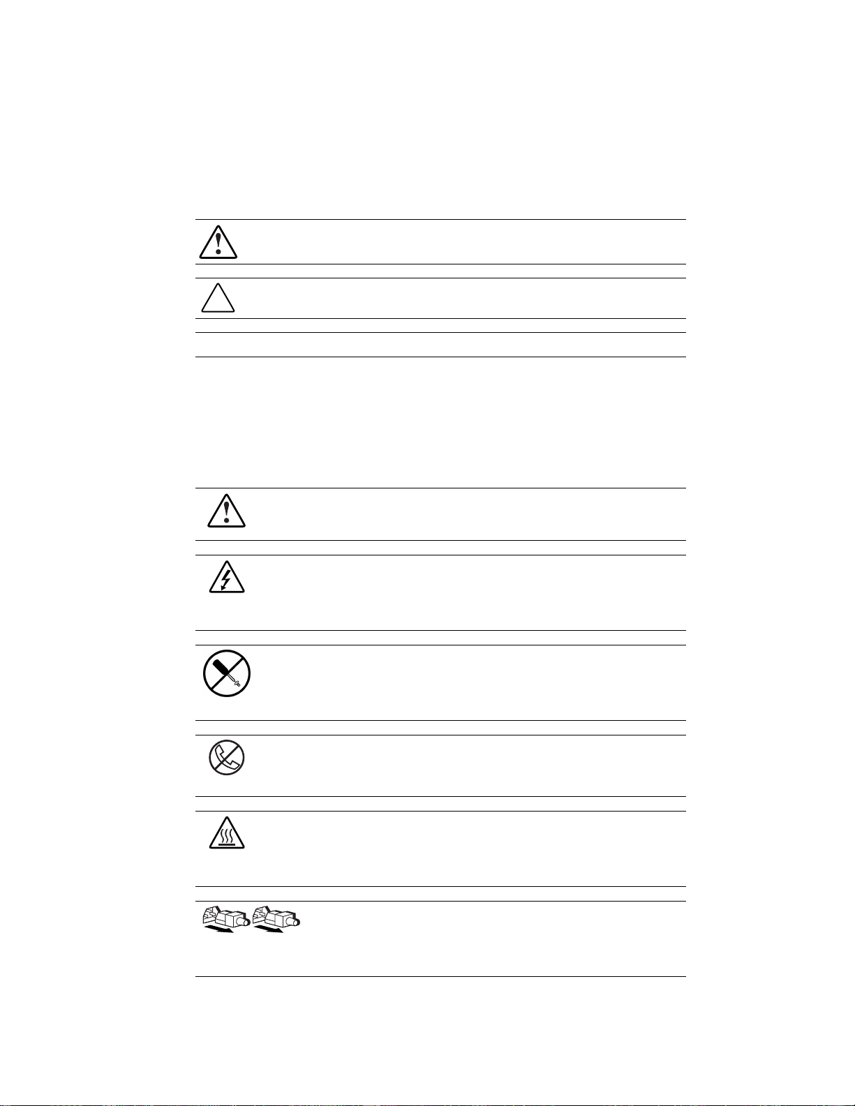
Symbols on Equipment
These symbols may be located on equipment in areas where hazardous conditions may exist.
This symbol in conjunction with any of the following symbols indicates the presence of a
potential hazard. The potential for injury exists if warnings are not observed. Consult your
documentation for specific details.
This symbol indicates the presence of hazardous energy circuits or electric shock hazards.
Refer all servicing to qualified personnel.
WARNING: To reduce the risk of injury from electric shock hazards, do not open this
enclosure. Refer all maintenance, upgrades, and servicing to qualified personnel.
This symbol indicates the presence of electric shock hazards. The area contains no user- or
field-serviceable parts. Do not open for any reason.
WARNING: To reduce the risk of injury from electric shock hazards, do not open this
enclosure.
This symbol on an RJ-45 receptacle indicates a Network Interface Connection.
WARNING: To reduce the risk of electric shock, fire, or damage to the equipment, do not
plug telephone or telecommunications connectors into this receptacle.
This symbol indicates the presence of a hot surface or hot component. If this surface is
contacted, the potential for injury exists.
WARNING: To reduce the risk of injury from a hot component, allow the surface to cool
before touching it.
These symbols on power supplies or systems indicate the equipment is supplied
by multiple sources of power.
WARNING: To reduce the risk of injury from electric shock, remove all power
cords to completely disconnect power from the system.
Page 9
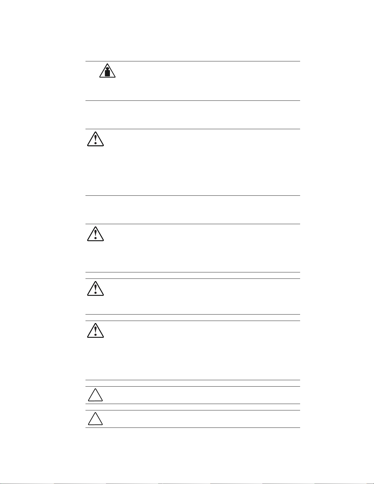
This symbol indicates that the component exceeds the recommended weight for
one individual to handle safely.
42 - 62 kg
93 - 137 lb
WARNING: To reduce the risk of personal injury or damage to the equipment,
observe local occupational health and safety requirements and guidelines for
manual material handling.
Rack Stability
WARNING: To reduce the risk of personal injury or damage to the equipment, be sure that:
■ The leveling jacks are extended to the floor.
■ The full weight of the rack rests on the leveling jacks.
■ The stabilizing feet are attached to the rack if it is a single rack installation.
■ The racks are coupled together in multiple rack installations.
■ Only one component is extended at a time. A rack may become unstable if more than one
component is extended for any reason.
Compaq Technician Notes
About This Guide ix
WARNING: Only authorized technicians trained by Compaq should attempt to repair this
equipment. All troubleshooting and repair procedures are detailed to allow only
subassembly/module-level repair. Because of the complexity of the individual boards and
subassemblies, no one should attempt to make repairs at the component level or to make
modifications to any printed wiring board. Improper repairs can create a safety hazard. Any
indications of component replacement or printed wiring board modifications may void any
warranty.
WARNING: To reduce the risk of personal injury from electric shock and hazardous energy
levels, do not exceed the level of repair specified in these procedures. Because of the
complexity of the individual boards and subassemblies, do not attempt to make repairs at the
component level or to make modifications to any printed wiring board. Improper repairs could
create conditions that are hazardous.
WARNING: To reduce the risk of electric shock or damage to the equipment:
■ If the system has multiple power supplies, disconnect power from the system by
unplugging all power cords from the power supplies.
■ Do not disable the power cord grounding plug. The grounding plug is an important safety
feature.
■ Plug the power cord into a grounded (earthed) electrical outlet that is easily accessible at
all times.
CAUTION: To properly ventilate your system, you must provide at least 30.5 cm (12 inches) of
clearance at the front and back of the computer.
CAUTION: The computer is designed to be electrically grounded. To ensure proper operation,
plug the AC power cord into a properly grounded AC outlet only.
Page 10

x Compaq ProLiant 8500 Server Maintenance and Service Guide
Getting Help
If you have a problem and have exhausted the information in this guide, you can get further
information and other help in the following locations:
■ User documentation
■ Compaq Service Quick Reference Guide
■ Service training guides
■ Compaq service advisories and bulletins
■ Compaq QuickFind
■ Compaq Insight Manager
■ Compaq Download Facility: Call 1-281-518-1418
Integrated Management Display
Some Compaq server models include a Compaq Integrated Management Display (IMD), an
integrated, 16 x 4 character display mounted on the front of the server. This display provides
easy-to-use menu-driven access to server information, including model number, LCD firmware
revision, and POST operations.
Page 11

Compaq Technical Support
In North America, call the Compaq Technical Phone Support Center at 1-800-OK-COMPAQ.
This service is available 24 hours a day, 7 days a week. For continuous quality improvement,
calls may be recorded or monitored.
Outside North America, call the nearest Compaq Technical Support Phone Center. Telephone
numbers for worldwide Technical Support Centers are listed on the Compaq website. Access the
Compaq website by logging on to the Internet:
http://www.compaq.com
Be sure to have the following information available before you call Compaq:
■ Technical support registration number (if applicable)
■ Product serial number
■ Product model name and number
■ Applicable error messages
■ Add-on boards or hardware
About This Guide xi
■ Third-party hardware or software
■ Operating system type and revision level
Compaq Website
The Compaq website has information on this product as well as the latest drivers and
Flash ROM images. You can access the Compaq website by logging on to the Internet:
http://www.compaq.com
Compaq Authorized Reseller
For the name of your nearest Compaq authorized reseller:
■ In the United States, call 1-800-345-1518.
■ In Canada, call 1-800-263-5868.
Elsewhere, see the Compaq website for locations and telephone numbers.
Page 12

Chapter 1
Illustrated Parts Catalog
This chapter provides the illustrated parts breakdown and a spare parts list for the
Compaq ProLiant™ 8500 Server with Intel Pentium III Xeon processor. See the table following
each illustration for the names of referenced spare parts.
Page 13
1-2 Compaq ProLiant 8500 Server Maintenance and Service Guide
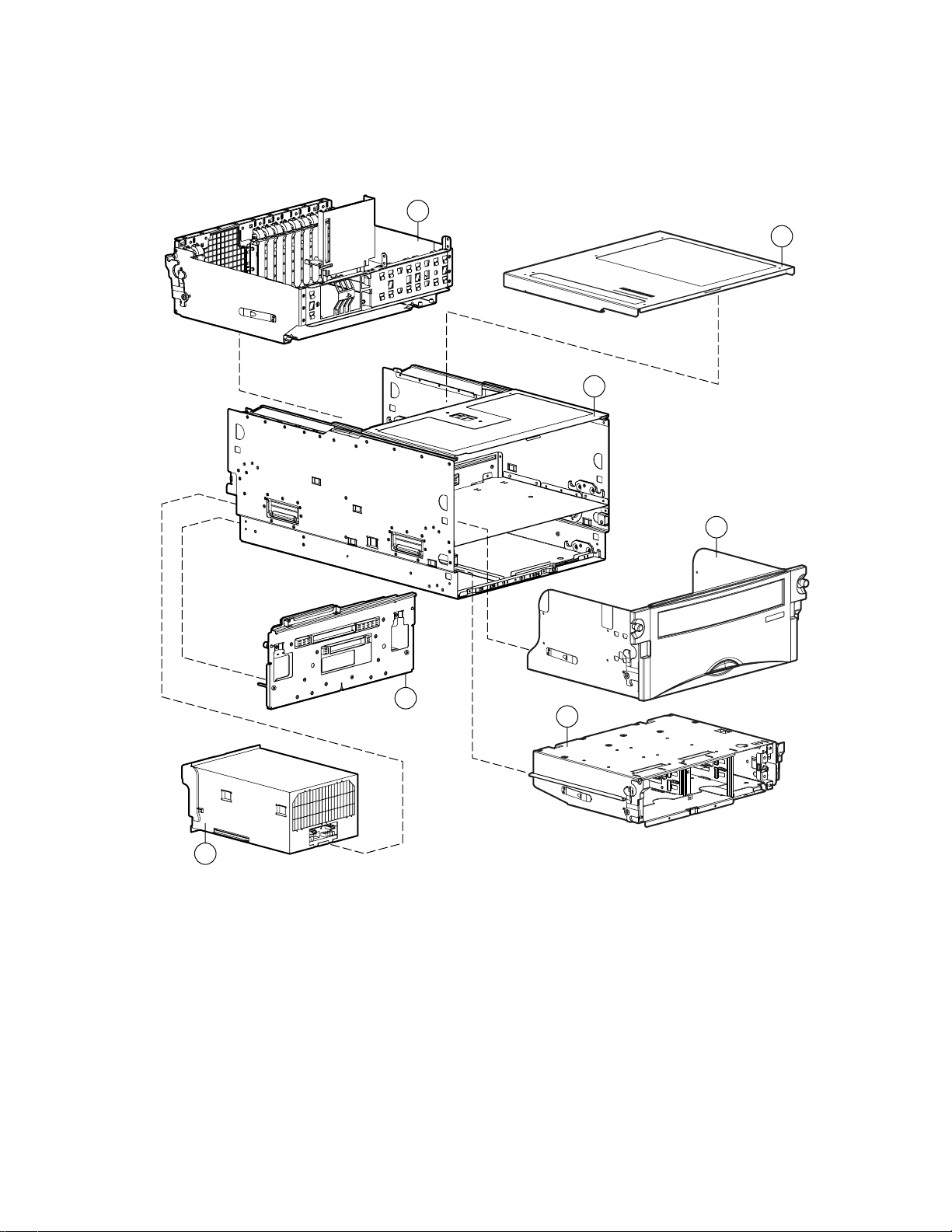
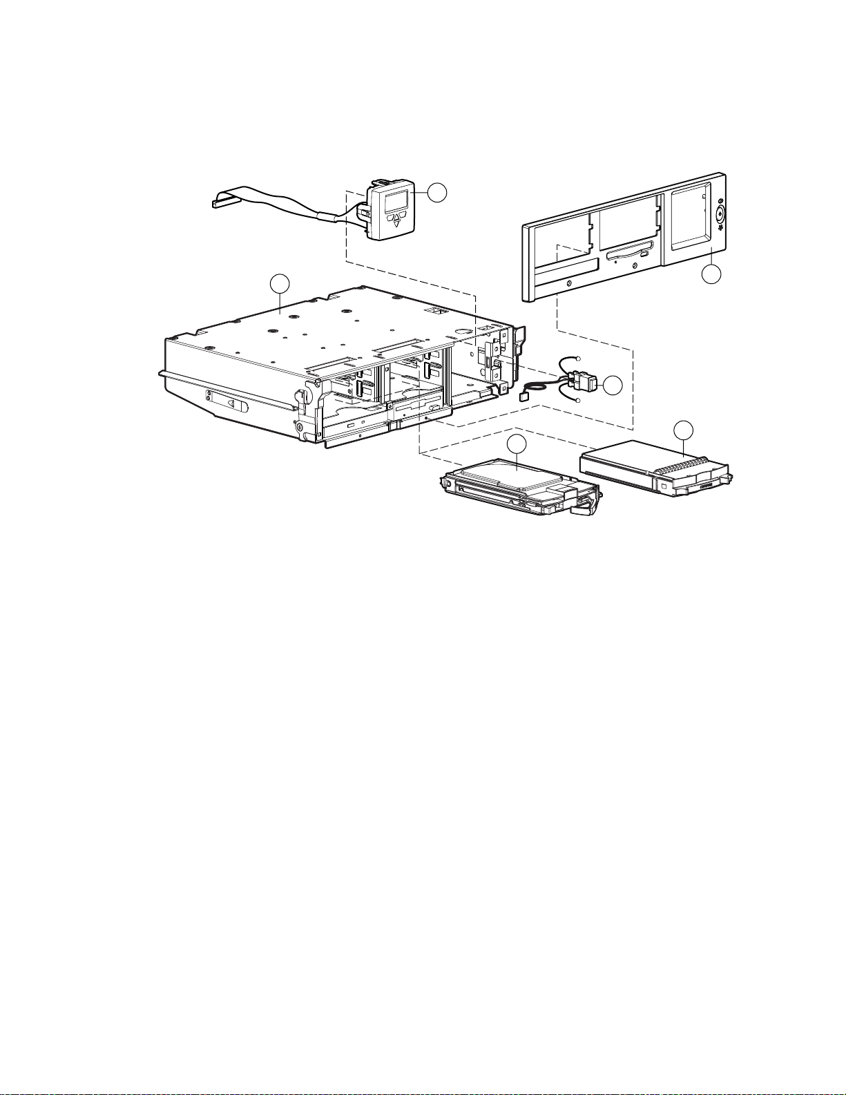
Mechanical Parts Exploded View
5
2
1
3
7
6
Figure 1-1. Mechanical parts exploded view
4
Page 14

Illustrated Parts Catalog 1-3
Table 1-1
Mechanical Spare Parts List
Item Description Spares Part Number
Chassis
1 Chassis 122231-001
2 Top access panel 122214-001
3 Processor module (with processor board) 122216-001
4 Media module
a) Drive tray drawer*
b) Drive tray bezel assembly*
c) Drive cage assembly*
d) Integrated Management Display (IMD)*
e) CD-ROM/1.44-MB diskette drive*
f) Media module bezel*
g) Bezel screws (qty 4)*
5 I/O module with I/O board 122229-001
System Components
6 Hot-pluggable power supply 500/1150 W 122235-001
Boards
7 System midplane assembly 122234-001
*Not shown
146446-001
Page 15
1-4 Compaq ProLiant 8500 Server Maintenance and Service Guide
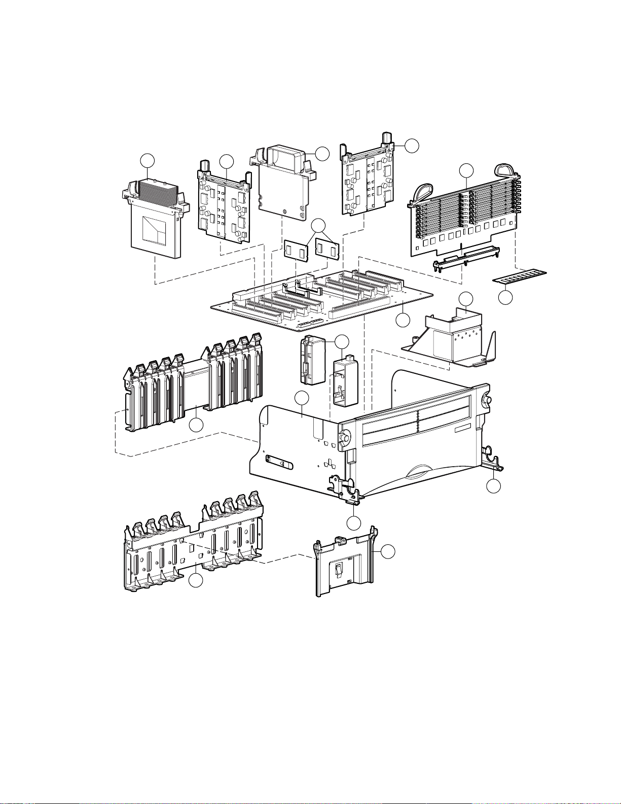
Processor and Memory Module Exploded View
8b
10a
12
16a
13
9
10b
8d
11
14
15a
8a
8c
Figure 1-2. Processor and memory module exploded view
15c
15d
15b
Page 16

Illustrated Parts Catalog 1-5
Table 1-2
Processor and Memory Module Spare Parts List
Item Description Spares Part Number
Boards
8 Processor module with processor board
a) Processor drawer
b) Processor/Memory host board
c) Processor guide, front
d) Processor guide, rear
e) Processor Power Module guide*
f) Memory guide (qty 2)*
g) Memory board insertion guide*
h) Air baffle assembly*
i) Neoprene bumpers (qty 2)*
j) Black keeper*
9 Processor, 550 MHz with 2-MB cache with heatpipe 153098-001
10 Processor Power Module
a) Redundant (Termination)
b) Redundant
11 Processor terminator board 122224-001
12 Memory board 122215-001
122216-001
312257-001
continued
Page 17

1-6 Compaq ProLiant 8500 Server Maintenance and Service Guide
Table 1-2
Processor and Memory Module Spare Parts List
Item Description Spares Part Number
13 Memory module, 256 MB, 60 ns 146489-001
14 Cache Accelerator (qty 2) 143887-001
continued
15 Miscellaneous plastics kit
a) Memory guide right and left (qty 2)
b) Terminator PPM guide
c) Drawer ejector right front
d) Drawer ejector left front
e) Fan cage plenum*
f) Plenum, 9 slot, top*
g) Plenum, 2 slot*
h) I/O plenum, 9 slot*
i) Port PCI retainers (qty 11)*
j) I/O slot double guide*
k) I/O slot triple guide*
l) Black keeper*
m) CPU drawer ejector, right*
n) CPU drawer ejector, left*
16 Miscellaneous hardware kit
a) Processor drawer air baffle cover
b) I/O center support bracket*
123185-001
123187-001
*Not shown
Page 18
Media Module Exploded View
Illustrated Parts Catalog 1-7
19
18
Figure 1-3. Media module exploded view
17b
20
22
21
Page 19

1-8 Compaq ProLiant 8500 Server Maintenance and Service Guide
Table 1-3
Media Module Spare Parts List
Item Description Spares Part Number
Chassis
17 Front bezel kit
a) Processor bezel*
b) Media bezel
c) IMD blank panel*
Assemblies
18 Media module 146446-001
19 IMD with cable 122223-001
20 Power switch assembly with LED 122233-001
Mass Storage
21 Wide Ultra2 hard drive with tray, 9 GB 1 inch 386536-001
22 LVDS 1-inch hard drive blank 122759-001
*Not shown
122236-001
Page 20
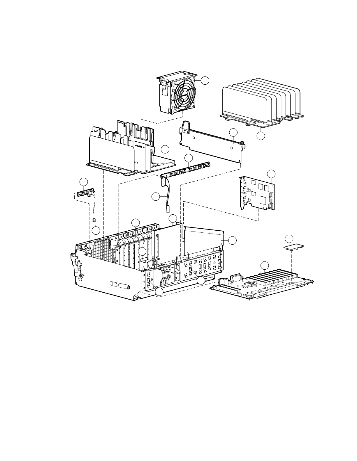
I/O Module Exploded View
Illustrated Parts Catalog 1-9
25
26a
26d
29i
29g
26c
29k
23d
29e
26b
29l
28b
29f
24
27
23b
23a
Figure 1-4. I/O module exploded view
Page 21

1-10 Compaq ProLiant 8500 Server Maintenance and Service Guide
Table 1-4
I/O Module Spare Parts List
Item Description Spare Part Number
Chassis
23 I/O Module (with I/O board)
a) I/O board
b) Array enabler board (replacement part is Item 40, Table 1-5)
c) I/O drawer sheet metal and plastics*
d) Fan cage
e) Fiber optic fan cage CA assembly*
f) Hot-pluggable fan interface*
g) PCI POC divider*
h) Fiber optic fan plenum CA assembly*
i) Hot-pluggable basket, 9 slot*
j) PCI Hot Plug switch cable, 9 slot*
k) PCI Hot Plug switch cable, 2 slot*
Assemblies
24 Hot-pluggable basket, 9 slot 122230-001
25 Hot-pluggable I/O fan 122225-001
Boards
26 PCI Hot Plug interface board with cables*
a) Lever PCB with insulation and latches, 2 slot
b) Lever PCB with insulation and latches, 9 slot
c) PCI Hot Plug switch cable, 9 slot
d) PCI Hot Plug switch cable, 2 slot
122229-001
122228-001
27 Compaq Netelligent™ 3131 Network Interface Controller (NIC) 152270-001
Miscellaneous
28 Miscellaneous hardware kit*
a) Processor drawer air baffle cover*
b) I/O center support bracket
123187-001
continued
Page 22

Illustrated Parts Catalog 1-11
Table 1-4
I/O Module Spare Parts List
Item Description Spare Part Number
continued
29 Miscellaneous plastics kit*
a) Memory guide right and left (qty 2)*
b) Terminator PPM guide*
c) Drawer ejector right front (qty 2)*
d) Drawer ejector left front (qty 2)*
e) Fan cage plenum
f) Plenum, 9 slot, top
g) Plenum, 2 slot
h) I/O plenum, 9 slot*
i) Port PCI retainers (qty 11)
j) Memory board connector guide front*
k) I/O slot double guide
l) I/O slot triple guide
m) Black keeper*
n) CPU drawer ejector, right*
o) CPU drawer ejector, left*
*Not shown
123185-001
Table 1-5
Miscellaneous and Options Spare Parts List
Item Description Spare Part Number
30 Miscellaneous screw kit*
a) Drawer ejector screws (qty 6)*
b) Diskette drive shoulder screws (qty 3)*
c) Diskette drive fastening screw*
31 Miscellaneous cable kit*
a) PCI Hot Plug switch cable, 9 slot*
b) PCI Hot Plug switch cable, 2 slot*
c) Diskette drive power cable*
d) CD-ROM drive cable*
e) Diskette drive data cable*
32 Cable management arm, 28-inch rails, slides* 123188-001
33 SCSI adapter (50/68)* 189638-001
123186-001
123184-001
continued
Page 23

1-12 Compaq ProLiant 8500 Server Maintenance and Service Guide
Table 1-5
Miscellaneous and Options Spare Parts List
Item Description Spare Part Number
34 Country kit* 152406-001
35 Return kit* 123189-001
36 Carton and buns, international* 123189-002
37 Maintenance and service guide* 124847-003
38 Illustrated parts map* 125792-003
39 Internal battery* 179322-001
40 Integrated Array Enabler Board* 122232-001
Options
41 Ethernet loopback RJ-45* 317465-001
42 Wide Ultra2 hard drive with tray, 9 GB, 1 inch, 7200 rpm* 104665-001
43 Wide Ultra2 hard drive with tray, 18 GB, 1 inch,7200 rpm* 104663-001
44 Wide Ultra3 hard drive with tray, 9.1 GB, 1 inch, 10000 rpm* 152188-001
45 Wide Ultra3 hard drive with tray, 18.2 GB, 1 inch, 10000 rpm* 152190-001
continued
46 Processor, 550 MHz with 512-KB cache and heatpipe* 153096-001
47 Processor, 550 MHz with 1-MB cache and heatpipe* 153097-001
48 Processor, 550 MHz with 2-MB cache and heatpipe* 153098-001
49 Processor, 700 MHz with 1-MB cache and heatpipe* 178943-001
50 Processor, 700 MHz with 2-MB cache and heatpipe* 178944-001
51 Memory module, 128 MB, 64 Mb, CL2 (qty 1)* 146488-001
52 Memory module, 256 MB, 128 Mb, CL2 (shown in Figure 1-2, Item 13) 146489-001
53 Memory module, 512 MB, 128 Mb, CL2 (qty 1)* 170515-001
54 Memory module, 256 MB, 64 Mb, CL2 (qty 1)* 170514-001
55 Memory module, 512 MB, 256 Mb, CL2 (qty 1)* 170515-001
56 Memory module, 512 MB, 128 Mb, CL3 (qty 1)* 170516-001
57 Memory module, 512 MB, 256 Mb, CL3 (qty 1)* 170517-001
58 Memory module 1 GB, 256 Mb, CL2 (qty 1)* 170518-001
59 Memory module 1 GB, 256 Mb, CL3 (qty 1)* 170519-001
*Not shown
Page 24

Chapter 2
Removal and Replacement Procedures
This chapter provides subassembly/module-level removal and replacement procedures for
Compaq ProLiant 8500 servers. After completing all necessary removal and replacement
procedures, run the Diagnostics program to verify that all components operate properly.
To service Compaq ProLiant 8500 servers, you might need the following:
Flat-blade screwdriver (four millimeter)
Torx T-15 screwdriver
Phillips screwdriver
From the Compaq SmartStart™ and Support Software CD:
System Configuration Utility software
Drive Array Advanced Diagnostics software (DAAD)
Array Diagnostics Utility software (ADU)
Diagnostics software
Page 25

2-2 Compaq ProLiant 8500 Server Maintenance and Service Guide
Electrostatic Discharge Information
A discharge of static electricity can damage static-sensitive devices or microcircuitry. Proper
packaging and grounding techniques are necessary precautions to prevent damage. To prevent
electrostatic damage, observe the following precautions:
Transport products in static-safe containers such as conductive tubes, bags, or boxes.
Keep electrostatic-sensitive parts in their containers until they arrive at static-free stations.
Cover workstations with approved static-dissipating material. Provide a wrist strap
connected to the work surface and properly grounded tools and equipment.
Keep the work area free of nonconductive materials, such as ordinary plastic assembly
aids and foam packing.
Make sure you are always properly grounded when touching a static-sensitive component
or assembly.
Avoid touching pins, leads, or circuitry.
Always place drives PCB assembly-side down.
Use conductive field service tools.
System Interconnect Status Indicators
Compaq ProLiant 8500 servers ship with system interconnect status indicators. System
interconnect status indicators consist of 17 LEDs that provide a closed-loop checking
mechanism for verifying proper component mating and interconnections between critical server
components. The indicators provide a visual aid to assist in isolating which components to
check if the server will not power up. These LEDs are located in the I/O module and can be
viewed through the top access panel. See Chapter 4, “Connectors, Switches, and LED
Indicators,” for more information.
Page 26
Preparation Procedures
System power in Compaq ProLiant 8500 servers does not completely shut off with the front
panel Power On/Standby switch. The switch toggles between On and Standby, rather than On
and Off. The Standby position removes power from most electronics and the drives, but portions
of the power supply, the Integrated Management Display (IMD), the system interlock circuitry,
and some internal circuitry remain active. You must disconnect all power cords from the server
to completely remove all power from the system.
WARNING: To reduce the risk of electric shock or damage to the equipment, disconnect power
from the server by unplugging all power cords from either the electrical outlet or the server.
IMPORTANT: To completely remove all power from the system, you must disconnect the power cord
from the server. In systems with multiple power supplies, you must disconnect all the power cords to
completely remove power from the system.
IMPORTANT: It is necessary to be knowledgeable of electrostatic discharge information before
conducting the preparation procedures. For electrostatic discharge information, see “Electrostatic
Discharge Information” earlier in this chapter.
Removal and Replacement Procedures 2-3
Hot-Pluggable Parts
Before beginning the removal of any serviceable parts, determine whether the part is
hot-pluggable or non-hot-pluggable. If it is hot-pluggable, do not perform a power shutdown of
the server. The access panels can be removed while the server is powered up without causing a
system shutdown. When the server is in Standby mode, portions of the power supply, auxiliary
power (+5V), and some internal circuitry will remain active.
Non-Hot-Pluggable Parts
If any serviceable parts are non-hot-pluggable, then the server must be shut down.
Non-hot-pluggable parts include the processor, Processor Power Module, system board,
memory board, and DIMMs. Refer to “Turning Off the Server” later in this chapter for complete
instructions.
IMPORTANT: It is not necessary to turn off the server to replace hot-pluggable devices, such as
PCI Hot Plug power supplies or hot-pluggable fans.
Page 27
2-4 Compaq ProLiant 8500 Server Maintenance and Service Guide
Before beginning any of the removal and replacement procedures for non-hot-pluggable
devices:
1. Press the Power On/Standby switch to Standby. This places the server in Standby mode,
thereby disabling the main power supply output and providing auxiliary power (+5V) to
the server. Standby does not disable main input power.
2. Verify that the system LED on the front panel, near the Power On/Standby switch, is off
and that the fan noise stops.
3. Disconnect all power cords from the server to disable all power to the server.
4. For some removal and replacement procedures, you must remove the server from the rack
and place it on a sturdy table or workbench. Refer to the Compaq ProLiant 8500 Setup
and Installation Guide for instructions.
Weight Warning
WARNING The Compaq ProLiant 8500 weighs 62 kilograms (137 pounds) when fully
assembled. To reduce the risk of personal injury or damage to the equipment:
Rack Warnings
42-62 kg
93-137 lb
■ Observe local health and safety requirements and guidelines for manual material
handling.
■ Obtain adequate assistance to lift and stabilize the product during installation or
removal.
■ Remove all pluggable modules and power supplies to reduce the overall weight of
the product.
WARNING: To reduce the risk of personal injury or damage to the equipment, be sure that:
■ The leveling jacks are extended to the floor.
■ The full weight of the rack rests on the leveling jacks.
■ The stabilizers are attached to the rack if it is a single-rack installation.
■ The racks are coupled together in multiple-rack installations.
■ Only one component is extended at a time. A rack may become unstable if more than one
component is extended for any reason.
Page 28
Server Warnings and Precautions
WARNING: To reduce the risk of personal injury from electric shock and hazardous energy
levels, only authorized service technicians should attempt to repair this equipment. Improper
repairs could create conditions that are hazardous.
WARNING: To reduce the risk of personal injury from hazardous energy or damage to the
equipment when working on energized servers:
■ Remove all watches, rings, and any other loose-fitting jewelry.
■ Do not use conductive tools inside the server that could bridge live parts.
WARNING: To reduce the risk of electric shock or damage to the equipment:
■ Do not disable the power cord grounding plug. The grounding plug is an important safety
feature.
■ Plug the power cord into a grounded electrical outlet that is easily accessible at all times.
■ Install the power supply before connecting the power cord to the power supply.
■ Unplug the power cord before removing the power supply from the server.
■ If the system has multiple power supplies, disconnect power from the system by
unplugging all power cords from the power supplies.
Removal and Replacement Procedures 2-5
WARNING: To reduce the risk of personal injury from hot surfaces, allow the internal system
components to cool before touching them.
CAUTION: Because the Compaq ProLiant 8500 server does not have safety interlocks, it is
possible for a unit to be operated without the cover and air baffles properly installed. This could
cause thermal damage in the system and may void your warranty. The rack-mountable
Compaq ProLiant 8500 server should always be operated with the system unit cover on. Proper
cooling will not be achieved if the system unit cover is removed for extended periods of time.
CAUTION: Protect the server from power fluctuations and temporary interruptions with a
regulating uninterruptible power supply (UPS). This device protects the hardware from damage
caused by power surges and voltage spikes and keeps the system in operation during a power
failure.
IMPORTANT: The installation of options and servicing of this product shall be performed by individuals
who are knowledgeable of the procedures, precautions, and hazards associated with equipment
containing hazardous energy circuits.
Page 29

2-6 Compaq ProLiant 8500 Server Maintenance and Service Guide
Compaq ProLiant 8500 Server
In Compaq ProLiant 8500 servers, options, and accessories are easily accessed through a sliding
top access panel and three removable modules: the processor and memory module, the media
module, and the I/O module. See Figure 2-1, Figure 2-2, Table 2-1, and Table 2-2 for
identification of these modules and other components.
1
2
5
4
3
Figure 2-1. Compaq ProLiant 8500 server – front view
Table 2-1
Front Components
Item Description
Processor and memory module
Media module
24X Max IDE CD-ROM drive
1.44-MB diskette drive
Integrated Management Display (IMD
Page 30
Removal and Replacement Procedures 2-7
1
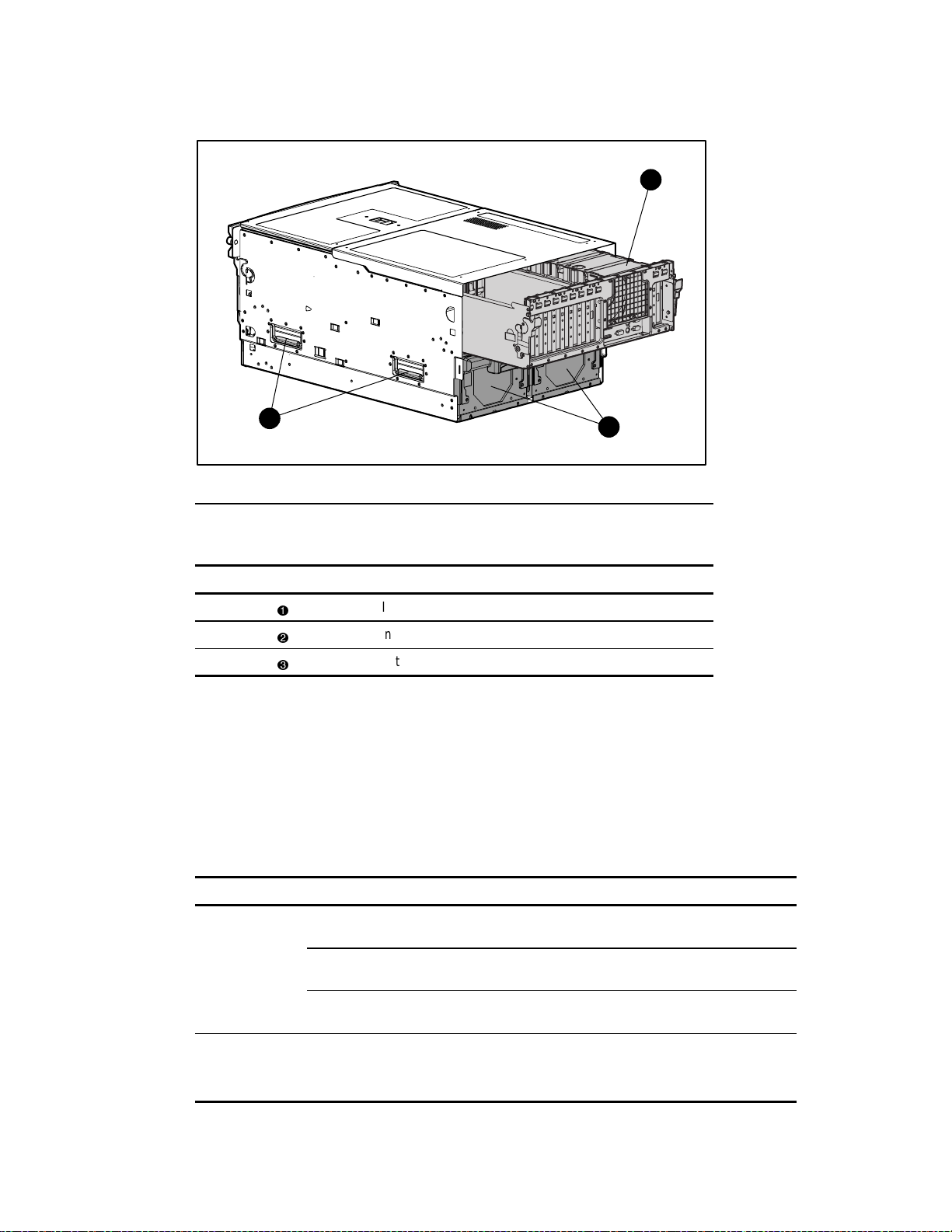
Figure 2-2. Compaq ProLiant 8500 server – rear view
Server Modules
The Compaq ProLiant 8500 server chassis facilitates the replacement or installation of hardware
using three removable modules and a sliding top access panel. Table 2-3 describes the contents
of the modules and how to access the components.
2
Table 2-2
Rear Components
Item Description
I/O module with system fans
Integrated server lift handles
Hot-pluggable power supplies
Module and Bay Components
3
Table 2-3
Module Contents To Access
PCI Hot Plug expansion slots Slide top access panel toward the front of the
server
I/O module and
system fans
Processor and
Memory Module
Configuration switches Slide top access panel toward the front of the
server.
Fans 1 and 2 Slide top access panel toward the front of the
server.
Processor (CPU) sockets Remove processor and memory module.
Processor Power Modules Remove processor and memory module.
continued
Page 31

2-8 Compaq ProLiant 8500 Server Maintenance and Service Guide
Table 2-3
Module and Bay Components
Module Contents To Access
continued
Processor and
memory module
Media module CD-ROM/diskette drives Remove media module.
Hard drive bays Hot-pluggable hard drives Access directly at front of server.
Top Access Panel
WARNING: To reduce the risk of personal injury from hot surfaces, allow the internal system
components to cool before touching them.
CAUTION: When the server is powered on, the access panel must be installed for proper
system cooling. Otherwise, component stress and permanent equipment damage may result.
The top access panel is opened to access the PCI Hot Plug expansion slots, system fans, and
configuration switches.
To open the top access panel:
1. Perform the preparation procedures. See “Preparation Procedures” earlier in this chapter.
Processor bus/core ratio switches Remove processor and memory module.
Cache Accelerator Remove processor and memory module.
Memory (DIMMs) Open processor and memory module. Remove
memory board.
2. Insert the access tool (Torx T-15 screwdriver or equivalent) into the access lock (if locked)
and turn the tool counter-clockwise .
1
2
Figure 2-3. Opening the access lock
Page 32

Removal and Replacement Procedures 2-9
NOTE: Compaq recommends leaving the top access panel locked during normal use.
3. Lift the forward-most edges of the top access panel
front of the server
Figure 2-4. Opening the top access panel
.
2
1
Reverse steps 1 through 3 to replace the top access panel.
, and then slide the panel toward the
1
Media Module Assembly
Mass storage in Compaq ProLiant 8500 servers is located in the media module. The media
module is capable of configuring a maximum of four 1-inch hot-pluggable Wide Ultra2 or
Wide Ultra3 SCSI hard drives. The media module supports two non-hot-pluggable media drive
bays:
One third-height drive bay occupied by a 1.44-MB diskette drive
One third-height drive bay occupied by a 24X Max (or higher) IDE CD-ROM drive
Page 33

2-10 Compaq ProLiant 8500 Server Maintenance and Service Guide
Media Module Bezel
To remove the media module bezel:
1. Perform the preparation procedures. See “Preparation Procedures” earlier in this chapter.
2. Remove the four screws securing the bezel to the module.
3. Lift up and pull the bezel away from the chassis.
Figure 2-5. Removing the bezel from the media module
Reverse steps 1 through 3 to replace the media module bezel.
Page 34

Media Module
To remove the media module from the server:
Removal and Replacement Procedures 2-11
CAUTION: Removable media blank bezels and hot-pluggable drive cage blanking panels must
be installed over unused mass storage and removable media device bays to maintain proper
airflow.
1. Perform the preparation procedures. See “Preparation Procedures Preparation Procedures”
earlier in this chapter.
2. Push in the sides of the cam levers
downward
1
Figure 2-6. Removing the media module
.
2
WARNING: To reduce the risk of personal injury from hot surfaces, allow the internal system
components to cool before touching them.
on the media module and rotate the top of the levers
Page 35

2-12 Compaq ProLiant 8500 Server Maintenance and Service Guide
3. Pull the media module out of the chassis until it contacts the module stop latch
4. Press in the module stop latches, then pull the module out of the chassis
3
3
Figure 2-7. Media module opened to stops
4
Reverse steps 2 and 4 to reinstall the module.
.
.
NOTE: Check the System Interconnect Status Indicator LEDs to ensure that the module is properly
seated. See Chapter 4, “Connectors, Switches, and LED Indicators.”
Page 36

Integrated Management Display
To remove the Integrated Management Display (IMD):
1. Perform the preparation procedures. See “Preparation Procedures” earlier in this chapter.
2. Remove the bezel. See “Media Module Bezel” earlier in this chapter.
3. Remove the media module. See “Media Module” earlier in this chapter.
Removal and Replacement Procedures 2-13
4. Disconnect the IMD cable from the media backplane board
Routing Diagram” later in this chapter.
Figure 2-8. Removing the IMD cable
. See “Media Module Cable
1
Page 37

2-14 Compaq ProLiant 8500 Server Maintenance and Service Guide
5. Press inward the two locking tabs on the rear of the display panel
6. Pull the IMD from the front of the server
2
Figure 2-9. Removing the IMD
.
Reverse steps 1 through 6 to replace the IMD.
.
2
3
2
Page 38

Hard Drive Blank
To remove a hard drive blank from a hard drive bay:
Removal and Replacement Procedures 2-15
1. Push the side of the retaining clip inward
2. Pull the hard drive blank from the bay
Figure 2-10. Removing a hard drive blank
.
.
2
Reverse steps 1 and 2 to replace a hard drive blank.
1
Page 39

2-16 Compaq ProLiant 8500 Server Maintenance and Service Guide
Hot-Pluggable Drive Replacement Guidelines
You should be able to hot-plug a drive during normal activity. Be aware, however, that
hot-plugging a disk drive will affect system performance and fault tolerance.
NOTE: Depending upon your configuration, a drive failure and the subsequent rebuild process will cause
storage subsystem performance degradation. For example, the replacement of a single drive on an array
with 50 logical drives will have less impact than if the array has three logical drives.
Although the system is operational, the disk subsystem may no longer be fault tolerant when a
disk drive is hot-plugged.
CAUTION: Fault tolerance will be lost until the removed drive is replaced and the rebuild
operation is completed (this will take several hours, even if the system is not busy while the
rebuild is in progress). If another drive in the array incurs an error during the period when fault
tolerance is unavailable, a fatal system error could result. If another drive fails during this
period, the entire contents of the array will be lost.
IMPORTANT: Perform a disk drive replacement during low activity periods whenever possible. In
addition, have a current valid backup available for the logical drives in the array of the drive being
replaced, even if drive replacement is being made during server downtime.
Hot-Pluggable Drive Replacement Precautions
Be aware of the following Compaq guidelines for safe hot-plug replacement:
Do not remove a degraded drive if any other member of the array is offline (the online
LED is off). No other drive in the array can be hot-plugged without data loss, unless
RAID 0+1 is used as a fault tolerant form. In this case, drives are mirrored in pairs. More
than one drive can fail and be replaced as long as the drive or drives they are mirroring are
online.
Refer to your Smart Array Controller user guide for information on fault tolerance
options.
Do not remove a degraded drive if any member of an array is missing (previously
removed and not yet replaced).
Do not remove a degraded drive if any member of an array is being rebuilt, unless the
drive being rebuilt has been configured as an online spare. The online LED for the drive
being rebuilt will flash, indicating that a replaced drive is being rebuilt from data stored on
the other drives.
NOTE: An online spare will not activate and start rebuilding after a predictive failure alert because the
degraded drive is still online. The online spare activates only after a drive in the array has failed.
Do not replace multiple degraded drives at the same time (for example, when the system is
off), or the fault tolerance may be compromised. When a drive is replaced, the controller
uses data from the other drives in the array to reconstruct data on the replacement drive. If
more than one drive is removed, a complete data set is not available to reconstruct data on
the replacement drive or drives, and permanent data loss could occur.
Page 40

CAUTION: Do not turn off an attached disk drive enclosure when the server containing the
Smart Array Controller is powered on. Also, do not turn on the server before turning on the disk
enclosure. If these ordering rules are not followed, the Smart Array Controller may mark the
drives in this enclosure as “failed,” which could result in permanent data loss.
CAUTION: Replace a hot-pluggable SCSI hard drive only when the drive LED is amber. Do not
remove a hot-pluggable SCSI hard drive if the online LED is green.
To remove a hot-pluggable SCSI hard drive:
Removal and Replacement Procedures 2-17
1. Push the tab to unlock the drive
.
2. Rotate the hot-pluggable drive ejector lever outward
3. Pull the hot-pluggable drive from the drive bay
Figure 2-11. Removing a hot-pluggable SCSI hard drive
.
.
1
2
3
Reverse steps 1 through 3 to replace a hot-pluggable SCSI hard drive.
Page 41

2-18 Compaq ProLiant 8500 Server Maintenance and Service Guide
Media Module Cable Routing Diagram
1 2 3 4 5
Figure 2-12. Media module cable routing diagram
Media Module Cable Routing
Item Description
CD-ROM drive signal cable
Diskette drive control and data cable
Diskette drive power cable
IMD cable
Power switch/LED/ambient air temperature sensor cable
Table 2-4
Page 42

Processor and Memory Module
Shipping Screw
To loosen the shipping screw:
1. Perform the preparation procedures. See “Preparation Procedures” earlier in this chapter.
2. Open the top access panel. See “Top Access Panel” earlier in this chapter.
Removal and Replacement Procedures 2-19
3. Lift up the fan intake plenum
4. Loosen the thumbscrew
Figure 2-13. Loosening the shipping screw
To tighten the shipping screw, repeat steps 1 through 3 and tighten the screw.
.
.
1
2
Page 43

2-20 Compaq ProLiant 8500 Server Maintenance and Service Guide
Opening and Removing the Processor and Memory Module
To open the processor and memory module:
1. Perform the preparation procedures. See “Preparation Procedures” earlier in this chapter.
2. Push in the sides of the cam levers
top of the levers downward
Figure 2-14. Opening the processor and memory module
on the processor and memory module, and rotate the
.
1
2
Page 44

Removal and Replacement Procedures 2-21
3. Pull the processor and memory module out of the chassis until it contacts the module
stop latches
.
4. Push the module stop latches inward, and slide the processor and memory module out of
the chassis
.
4
3
Figure 2-15. Removing the processor and memory module
Reverse steps 1 through 4 to reinstall and close the processor and memory module.
Page 45

2-22 Compaq ProLiant 8500 Server Maintenance and Service Guide
Memory Board
WARNING: To reduce the risk of personal injury from hot surfaces, allow the internal system
components to cool before touching them.
To remove a memory board:
1. Perform the preparation procedures. See “Preparation Procedures” earlier in this chapter.
2. Open the processor and memory module drawer. See “Memory Board Opening and
Removing the Processor and Memory Module” earlier in this chapter.
3. Rotate the memory board ejectors outward
the processor board
.
, and then remove the memory board from
4. Place the memory expansion board, components facing up, on a flat surface.
1
1
Figure 2-16. Removing the memory board
2
IMPORTANT: The memory board is part of the system interconnect scheme and must be seated
properly for server startup.
Reverse steps 1 through 4 to replace the memory board.
Page 46

Dual Inline Memory Modules
Compaq ProLiant 8500 servers ship with 128-MB, 256-MB, 512-MB, or 1-GB Synchronous
DRAM (SDRAM) Dual Inline Memory Modules (DIMMs) installed. Memory can be expanded
to a maximum of 16 GB. Install SDRAM DIMM module pairs, one module at a time, into the
proper sockets.
CAUTION: Compaq recommends using only Compaq SDRAM DIMMs. DIMMs from other
sources may adversely affect data integrity.
Adhere to the following guidelines when installing or replacing memory:
DIMMs must be installed in pairs.
Use only 128-MB, 256-MB, 512-MB, or 1-GB SDRAM DIMMs.
Both DIMMs of a given bank must be the same size, type, and speed.
The recommended SDRAM DIMM installation order is to begin with Bank 1, DIMMs 1 and 2,
then populate toward Bank 8.
Figure 2-17 shows DIMM memory bank locations 1 through 8 and DIMMs 1 through 16 on the
memory expansion board in Compaq ProLiant 8500 servers.
Removal and Replacement Procedures 2-23
Memory
DIMM 2
DIMM 4
DIMM 6
DIMM 8
DIMM 10
DIMM 12
DIMM 14
DIMM 16
Banks
1
2
3
4
5
6
7
8
Figure 2-17. Locating DIMM sockets on memory banks 1 through 8
DIMM 1
DIMM 3
DIMM 5
DIMM 7
DIMM 9
DIMM 11
DIMM 13
DIMM 15
Page 47

2-24 Compaq ProLiant 8500 Server Maintenance and Service Guide
Any combination of SDRAM DIMMs can be used as long as the guidelines explained earlier are
followed. Examples of possible SDRAM DIMM upgrade combinations for each memory board
are shown in Table 2-5.
Table 2-5
Examples of SDRAM DIMM Upgrade Combinations
Total
Memory Bank 1 Bank 2 Bank 3 Bank 4 Bank 5 Bank 6 Bank 7 Bank 8
256 MB 2 x 128 MB
512 MB 2 x 128 MB 2 x 128 MB
1 GB 2 x 128 MB 2 x 128 MB 2 x 128 MB 2 x 128 MB
1.5 GB 2 x 128 MB 2 x 128 MB 2 x 128 MB 2 x 128 MB 2 x 128 MB 2 x 128 MB
2 GB 2 x 256 MB 2 x 256 MB 2 x 256 MB 2 x 256 MB
4 GB 2 x 256 MB 2 x 256 MB 2 x 256 MB 2 x 256 MB 2 x 256 MB 2 x 256 MB 2 x 256 MB 2 x 256 MB
4 GB 2 x 512 MB 2 x 512 MB 2 x 512 MB 2 x 512 MB
6 GB 2 x 512 MB 2 x 512 MB 2 x 512 MB 2 x 512 MB 2 x 512 MB 2 x 512 MB
8 GB 2 x 512 MB 2 x 512 MB 2 x 512 MB 2 x 512 MB 2 x 512 MB 2 x 512 MB 2 x 512 MB 2 x 512 MB
16 GB 2 x 1 GB 2 x 1 GB 2 x 1 GB 2 x 1 GB 2 x 1 GB 2 x 1 GB 2 x 1 GB 2 x 1 GB
Page 48

Removal and Replacement Procedures 2-25
To remove a DIMM:
1. Perform the preparation procedures. See “Preparation Procedures” earlier in this chapter.
2. Remove the processor and memory module drawer. See “Opening and Removing the
Processor and Memory Module” earlier in this chapter.
3. Remove the memory board. See “Media Module” earlier in this chapter.
4. Press outward on the socket latches at each end of the DIMM
5. Remove the DIMM from the memory expansion board
2
1
Figure 2-18. Removing a DIMM from the memory board
Reverse steps 1 through 5 to replace a DIMM.
.
.
1
CAUTION: The ejectors prevent the memory expansion board from lying completely flat.
Inserting a DIMM without counter pressure applied behind the socket to the back of the
expansion board can cause the memory expansion board to flex and could result in damage.
Always support the memory expansion board or apply counter pressure while inserting a DIMM.
IMPORTANT: Make sure that both latches are secured when the DIMM is installed.
Page 49

2-26 Compaq ProLiant 8500 Server Maintenance and Service Guide
Processor Board Layout
Figure 2-19 and Table 2-6 show the processor board layout and processor socket numbering.
12
1
11
8765432
13
14
Figure 2-19. Processor board layout
Item Description
Processor socket 1 and associated power module socket
Processor socket 2 and associated power module socket
Processor socket 3 and associated power module socket
Processor socket 4 and associated power module socket
Processor socket 5 and associated power module socket
Processor socket 6 and associated power module socket
Processor socket 7 and associated power module socket
Processor socket 8 and associated power module socket
Processor bus termination power module
Memory board socket
Bus 1 cache accelerator socket
9
10
Table 2-6
Processor Board Layout
Bus 2 cache accelerator socket
Bus 1 processor/core ratio switch (SW1)
Bus 2 processor/core ratio switch (SW2)
Page 50

Processor
Removal and Replacement Procedures 2-27
CAUTION: Handle the processor only by the ejectors. If you must set the processor down, lay it
down on the side with the hologram to prevent damage to the heat pipes and fins.
IMPORTANT: If you remove a processor, a processor terminator board must be reinstalled in the slot
before powering up the server.
To remove a processor:
1. Perform the preparation procedures. See “Preparation Procedures” earlier in this chapter.
2. Remove the processor and memory module. See “Opening and Removing the Processor
and Memory Module” earlier in this chapter.
3. Rotate the front and rear ejector levers on the processor outward until the processor is
disconnected from the connector
.
4. Remove the processor by lifting up on the ejectors
1
1
2
Figure 2-20. Removing a processor
Reverse steps 1 through 4 to replace a processor.
.
Page 51

2-28 Compaq ProLiant 8500 Server Maintenance and Service Guide
CAUTION: The Processor Power Module must be installed before you install the accompanying
processor. Attempting to install the Processor Power Module afterward could damage its
electronic components.
CAUTION: The server will NOT boot if Intel Pentium III Xeon 500/550-MHz processors and
Pentium III Xeon 700-MHz or higher speed processors are installed in the same server.
IMPORTANT: When installing a processor, push down on both levers simultaneously. The server may
not recognize the processor if it is not properly installed.
NOTE: The System ROM will automatically detect the presence of the new processor and clear the POST
processor failure message.
Page 52

Processor Power Module
CAUTION: The processor must be removed before you remove the Processor Power Module.
Attempting to remove the Processor Power Module before removing the processor could
damage its electronic components.
To remove a Processor Power Module:
1. Perform the preparation procedures. See “Preparation Procedures” earlier in this chapter.
2. Remove the processor and memory module. See “Opening and Removing the Processor
and Memory Module” earlier in this chapter.
Removal and Replacement Procedures 2-29
3. Rotate the ejector levers on the Processor Power Module outward
4. Remove the Processor Power Module
1
2
Figure 2-21. Removing a Processor Power Module
.
Reverse steps 1 through 4 to replace the Processor Power Module.
.
CAUTION: The Processor Power Module must be installed before you install the accompanying
processor. Attempting to install the Processor Power Module afterward could damage its
electronic components.
NOTE: The Processor Power Module is keyed for correct alignment.
Page 53

2-30 Compaq ProLiant 8500 Server Maintenance and Service Guide
Processor Terminator Board
To remove a processor terminator board:
1. Rotate the ejector levers on the processor terminator board
2. Remove the processor terminator board
2
1
Figure 2-22. Removing a processor terminator board
.
2
1
Reverse steps 1 and 2 to replace a processor terminator board.
outward.
Page 54

Middle Air Baffle
IMPORTANT: The middle air baffle must be installed during operation of the server to ensure proper
processor cooling.
To remove the middle air baffle:
Removal and Replacement Procedures 2-31
1. Loosen the thumbscrew of the middle air baffle
2. Lift the baffle upward
3. Remove the middle air baffle
1
Figure 2-23. Removing the middle air baffle
.
.
2
.
3
Reverse steps 1 through 3 to replace the middle air baffle.
Page 55

2-32 Compaq ProLiant 8500 Server Maintenance and Service Guide
Cache Accelerators
IMPORTANT: Cache accelerators must be installed when processors are installed on both buses.
To remove a cache accelerator:
1. Perform the preparation procedures. See “Preparation Procedures” earlier in this chapter.
2. Remove the processor and memory module. See “Opening and Removing the Processor
and Memory Module” earlier in this chapter.
3. Loosen the thumbscrew of the middle air baffle and lift the baffle upward to allow access
to the cache accelerator. See “Middle Air Baffle” earlier in this chapter.
4. Locate the cache accelerator.
5. Push down on the release lever on the side of the cache accelerator slot
6. Remove the cache accelerator
1
2
Figure 2-24. Removing a cache accelerator
.
Reverse steps 1 through 6 to replace the cache accelerator.
.
NOTE: Cache accelerator modules are keyed to ensure correct alignment.
Page 56

After replacing the cache accelerator, complete the following steps to clear the cache accelerator
POST Error 220:
1. Reboot the server and press F9 to enter the ROM-based System Configuration Utility.
2. Once in the utility, select Advanced Options.
3. Select Set Cache Accelerator Corrected.
4. Select the slot, either 1 or 2, that has been corrected.
5. Press ESC twice, and then press F10 to save.
The bit in NVRAM is cleared at this point. If the cache accelerator replacement has been
successful, POST Error 220 should no longer appear at reboot.
Processor Board
The processor board is located at the bottom of the processor and memory module and should
not be removed. If there is a need to replace the processor board, a new processor module with
system board must be ordered. The new processor board will be attached to the bottom of the
module, along with processor guide rails.
Removal and Replacement Procedures 2-33
Page 57

2-34 Compaq ProLiant 8500 Server Maintenance and Service Guide
I/O Module
The I/O module is located at the rear of the server. Remove it to replace or service
non-hot-pluggable components or to access other components in the I/O module.
Removing the I/O Module from Tower Model Servers
To remove the I/O module:
1. Perform the preparation procedures. See “Preparation Procedures” earlier in this chapter.
2. Open the top access panel. See “Top Access Panel” earlier in this chapter.
3. Loosen the shipping screw, if necessary. See “Shipping Screw” earlier in this chapter.
4. Push in on the sides of the stop latches
downward
5. Pull the I/O module out of the chassis
Figure 2-25. Partially removing the I/O module
.
1
2
on the I/O module, and rotate the cam levers
until it catches on the module stop latch.
3
Page 58

Removal and Replacement Procedures 2-35
6. To completely remove the I/O module from the chassis, press in on the module stop
latches
Figure 2-26. Removing the I/O module
, and pull the module out of the chassis .
4
5
Reverse steps 1 through 6 to reinstall the module in the server.
Page 59

2-36 Compaq ProLiant 8500 Server Maintenance and Service Guide
Removing the I/O Module from a Rack-Mounted Server
To remove the I/O module from a rack-mounted server:
1. Slide the top access panel forward. See “Top Access Panel” earlier in this chapter.
2. Loosen the internal shipping screw. See “Shipping Screw” earlier in this chapter.
3. Disconnect all cables from the rear of the I/O module.
4. Loosen the green thumbscrew that secures the cable management arm and bracket to the
I/O module
5. Move the bracket, with cable management arm attached, slightly up and then back from
the server
.
so that it is possible to access the cam levers on the I/O module (Step 7).
2
1
Figure 2-27. Disconnecting the cable management bracket from the I/O module
Page 60

Removal and Replacement Procedures 2-37
6. Rotate the cable management arm to the left and out of the way
3
Figure 2-28. Rotating the cable management arm to the left
.
7. Push in on the sides of the stop latches and rotate the cam levers downward.
See “Removing the I/O Module from Tower Model Servers” earlier in this chapter.
8. Press the stop latches inward, and remove the I/O module just enough to clear the stops.
See “Removing the I/O Module from Tower Model Servers” earlier in this chapter.
9. Reach into the rack and pull out the I/O module, making sure that the I/O module stop
latches clear the sides of the rack.
Reverse steps 1 through 9 to reinstall the I/O module in the server.
Page 61

2-38 Compaq ProLiant 8500 Server Maintenance and Service Guide
Locating the I/O Expansion Slots
The I/O expansion slots are located on the I/O board in the I/O module. The I/O board in the
Compaq ProLiant 8500 server uses two 33-MHz PCI buses and one 66-MHz bus. The
PCI expansion slots associated with each of the three PCI buses are identified in Figure 2-29,
Figure 2-30, and Table 2-7. Bus balancing is not required.
WARNING: To reduce the risk of personal injury from hot surfaces, allow the internal system
components to cool before touching them.
2 1 3
1 2 3 4 5 6 7 8 9 10 11
Figure 2-29. Diagram of I/O slot connections from the rear of the server
67891011
4
5
Figure 2-30. Bus distribution of PCI Hot Plug slots
123
Page 62

Removal and Replacement Procedures 2-39
Table 2-7
Bus Distribution of PCI Hot Plug Slots
Bus Number Associated PCI Bus PCI Hot Plug Slot Number
1
2
3
NOTE: The I/O expansion board slots are numbered from right to left as you face the front of the server.
I/O Expansion Slot Cover
To remove the I/O expansion slot cover:
1. Press down on the top of the expansion slot release lever
2. Remove the expansion slot cover
2
PCI bus primary, 64 bit, 33 MHz
PCI bus secondary 64 bit, 33 MHz
PCI bus tertiary 64 bit, 66 MHz
.
1
Slots through
Slots through
Slots and
and push the lever up .
3
Figure 2-31. Removing the I/O expansion slot cover
Reverse steps 1 and 2 to replace the I/O expansion slot cover.
Page 63

2-40 Compaq ProLiant 8500 Server Maintenance and Service Guide
PCI Expansion Board
CAUTION: DO NOT open the slot release lever unless the green PCI Hot Plug LED indicator is
off. System power down and subsequent data loss could occur.
To remove a PCI expansion board:
1. Perform the preparation procedures. See “Preparation Procedures” earlier in this chapter.
2. Open the top access panel. See “Top Access Panel” earlier in this chapter.
3. Use the PCI Hot Plug button to turn power off to the slot
. The green LED flashes
during the power down transition and turns off when power down is complete. For more
information on PCI Hot Plug LED indicators, see Chapter 4, “Connectors, Switches, and
LED Indicators.”
NOTE: Pressing the PCI Hot Plug button within five seconds of the first press cancels the action.
1
Figure 2-32. Accessing the PCI Hot Plug button
Page 64

Removal and Replacement Procedures 2-41
4. When the green LED is off, disconnect the cables to the PCI expansion board.
5. Press down on the top of the expansion slot
6. Lift up the I/O plenum
7. Remove the PCI expansion board
.
.
, and open the slot release lever .
8. Return power to the slot through the PCI Hot Plug button. The green LED will flash
during the power up transition and will glow steadily when power up is complete. For
more information on PCI Hot Plug LED indicators, see Chapter 4, “Connectors, Switches,
and LED Indicators.”
5
2
3
4
Figure 2-33. Removing a PCI expansion board
Reverse steps 1 through 8 to replace the PCI expansion board.
IMPORTANT: If you have installed the Integrated Array Bypass kit, you will not be able to use it with the
options installed in slots 10 or 11.
IMPORTANT: If only removing the board, install an expansion slot cover in the slot.
IMPORTANT: Remove any shipping brackets from the replacement board prior to installation.
Page 65

2-42 Compaq ProLiant 8500 Server Maintenance and Service Guide
9-Slot Hot-Pluggable Basket
To remove the 9-slot hot-pluggable basket:
1. Perform the preparation procedures. See “Preparation Procedures” earlier in this chapter.
2. Open the top access panel. See “Top Access Panel” earlier in this chapter.
3. Remove all installed boards in slots 1 through 9. See “PCI Expansion Board” earlier in
this chapter.
4. Flex the snap tab holding the array enabler daughterboard
1
Figure 2-34. Removing the array enabler daughterboard
and remove the board .
2
Page 66

Removal and Replacement Procedures 2-43
5. Remove the screw
6. Disengage the two hot-pluggable basket tabs
securing the hot-pluggable basket to the chassis.
near slot 1 from the I/O module chassis.
7. Remove the hot-pluggable basket from of the I/O module
5
Figure 2-35. Removing the 9-slot hot-pluggable basket
.
4
4
3
Reverse steps 1 through 7 to replace the 9-slot hot-pluggable basket.
Page 67

2-44 Compaq ProLiant 8500 Server Maintenance and Service Guide
Hot-Pluggable Fans
The Compaq ProLiant 8500 server ships with two hot-pluggable fans. Fan 1 is closest to the rear
of the server. Each fan has LEDs that indicate the status of the fan. For more information on the
hot-pluggable fan LEDs, see Chapter 4, “Connectors, Switches, and LED Indicators.”
1
2
Figure 2-36. Top view of hot-pluggable fans
Hot-Pluggable Fans
Item Description
Hot-pluggable fan 1
Hot-pluggable fan 2
Table 2-8
Page 68

Removal and Replacement Procedures 2-45
To remove a hot-pluggable fan from the server:
CAUTION: Never remove both hot-pluggable fans while the server is powered up. Overheating
and damage to hardware could result. If the appropriate Compaq software drivers are installed,
the operating system software will initiate a power shutdown in the event of overheating.
1. Perform the preparation procedures. See “Preparation Procedures” earlier in this chapter.
2. Open the top access panel. See “Top Access Panel” earlier in this chapter.
3. Press in the locking latches
of the module
1
Figure 2-37. Removing a hot-pluggable fan
.
and remove the failed hot-pluggable fan (either 1 or 2) from
2
Reverse steps 1 through 3 to replace a hot-pluggable fan.
Page 69

2-46 Compaq ProLiant 8500 Server Maintenance and Service Guide
Fan Cage Assembly
To remove the fan cage assembly:
1. Perform the preparation procedures. See “Preparation Procedures” earlier in this chapter.
2. Remove the I/O module. See the sections on removing the I/O Modules earlier in this
chapter.
3. Remove any PCI expansion boards in slots 10 and 11. See “PCI Expansion Board” earlier
in this chapter.
4. Remove the hot-pluggable I/O fans. See “Hot-Pluggable Fans” earlier in this chapter.
5. Loosen the three screws securing the fan cage assembly to the I/O module
6. Remove the fan cage assembly
2
Figure 2-38. Removing the fan cage assembly
.
1
Reverse steps 1 through 6 to replace the fan cage assembly.
.
Page 70

I/O Module Central Support Bracket
To remove the I/O module central support bracket:
1. Perform the preparation procedures. See “Preparation Procedures” earlier in this chapter.
2. Remove the I/O module. See the sections on removing the I/O modules earlier in this
chapter.
3. Remove the fan cage assembly. See “Fan Cage Assembly” earlier in this chapter.
Removal and Replacement Procedures 2-47
4. Loosen the thumbscrew securing the bracket to the chassis
5. Remove the bracket
Figure 2-39. Removing the I/O module central support bracket
.
2
.
1
Reverse steps 1 through 5 to replace the I/O module central support bracket.
Page 71

2-48 Compaq ProLiant 8500 Server Maintenance and Service Guide
I/O Plenum Top and Plenum
To remove the I/O plenum top and plenum:
1. Lift up the plenum top
2. Remove the plenum top
3
Figure 2-40. Removing the I/O plenum top
3. Lift up the plenum
, and flex each end to release the catches .
.
1
, and flex each end to release the catches .
2
4. Remove the plenum
6
Figure 2-41. Removing the I/O plenum
.
4
5
Reverse steps 1 through 4 to replace the I/O plenum and plenum top.
Page 72

Fan Cage Plenum
To remove the fan cage plenum from the I/O module:
Removal and Replacement Procedures 2-49
1. Lift up the fan cage plenum
2. Remove the plenum
2
Figure 2-42. Removing the fan cage plenum
, and flex each end until the catches are released .
.
3
1
Reverse steps 1 and 2 to replace the fan cage plenum.
Page 73

2-50 Compaq ProLiant 8500 Server Maintenance and Service Guide
2-Slot Plenum
To remove the 2-slot plenum:
1. Locate the 2-slot plenum attached to the side of the fan cage plenum.
2. Remove the fan cage plenum. See “Fan Cage Plenum” earlier in this chapter.
3. Slightly separate the fan cage plenum walls that trap the 2-slot plenum.
4. Remove the 2-slot plenum.
Figure 2-43. Removing the 2-slot plenum
Reverse steps 1 through 4 to replace the 2-slot plenum.
Page 74

Removal and Replacement Procedures 2-51
Hot-Pluggable Power Supply and Midplane Assembly
Compaq ProLiant 8500 servers support up to two hot-pluggable, redundant power supplies.
Hot-Pluggable Power Supply
The system power in the Compaq ProLiant 8500 server does not have to be shut off to replace
one of the power supplies.
To replace a hot-pluggable power supply with the system power on:
1. Remove the power cord from the power supply.
2. Squeeze upward on the release tab in the middle of the power supply handle
.
3. Pull the power supply handle down and slide the power supply out of the chassis
IMPORTANT: Use only power supply part number 122235-001 for the Compaq ProLiant 8500 server.
Power supplies from other servers will not fit.
NOTE: When you remove the power supply, a spring-loaded trap door closes to block the opening. This
door preserves the air path required to cool the internal components of the server.
1
3
2
.
Figure 2-44. Removing a hot-pluggable power supply
Reverse steps 1 through 3 to replace the hot-pluggable power supply.
Page 75

2-52 Compaq ProLiant 8500 Server Maintenance and Service Guide
System Midplane Assembly
To remove the system midplane assembly:
1. Perform the preparation procedures. See “Preparation Procedures” earlier in this chapter.
2. Open the top access panel. See “Top Access Panel” earlier in this chapter.
3. Remove and disconnect all modules and power supplies. See sections on removing the I/O
module, “Media Module,” “Processor and Memory Module,” and “Hot-Pluggable Power
Supply” earlier in this chapter.
4. Loosen the two thumbscrews securing the system midplane assembly to the chassis
5. Remove the board from the chassis
Figure 2-45. Removing the system midplane assembly
.
1
2
Reverse steps 1 through 5 to replace the system midplane assembly.
.
Page 76

Power On/Standby Switch Assembly
To remove the Power On/Standby switch:
1. Perform the preparation procedures. See “Preparation Procedures” earlier in this chapter.
2. Remove the media module bezel. See “Media Module Bezel” earlier in this chapter.
3. Remove the media module. See “Media Module” earlier in this chapter.
4. Unplug the IMD cable from the media backplane board. See “Media Module Cable
Routing Diagram” earlier in this chapter.
5. Remove the IMD. See “Integrated Management Display” earlier in this chapter.
Removal and Replacement Procedures 2-53
6. Disconnect the Power On/Standby switch connector from the media backplane board
See “Media Module Cable Routing Diagram” earlier in this chapter.
7. Loosen the thumbscrew that secures the power switch plate to the media backplane
board
Figure 2-46. Unplugging the power switch cable and loosening the thumbscrew
.
2
1
.
Page 77

2-54 Compaq ProLiant 8500 Server Maintenance and Service Guide
8. Remove the power switch plate from the media module
3
Figure 2-47. Removing the power switch plate from the media module
.
9. Squeeze the grommets around the LEDs, and remove the LEDs from the grommets.
Remove the thermistor from the bracket assembly
10. Pull the switch assembly out of the power switch plate
.
.
4
5
4
Figure 2-48. Removing the Power On/Standby switch from the power switch plate
Reverse steps 1 through 10 to replace the Power On/Standby switch assembly.
NOTE: The Power On/Standby switch LED is in the top position, and the thermistor is in the bottom
position.
Page 78

Internal Battery
To remove the internal battery:
1. Perform the preparation procedures. See “Preparation Procedures” earlier in this chapter.
2. Open the top access panel. See “Top Access Panel” earlier in this chapter.
3. Locate the battery on the I/O board behind slots 10 and 11.
Removal and Replacement Procedures 2-55
4. Pull the battery out of the battery socket
CAUTION: Replace the battery within 15 minutes of removal to avoid data loss.
1
Figure 2-49. Removing the internal battery (fan guide and other plastics not shown)
.
2
Reverse steps 1 through 4 to replace the battery .
CAUTION: Loss of BIOS settings will occur if the lithium battery is removed. BIOS settings must
be reconfigured whenever the battery is replaced.
CAUTION: Batteries, battery packs, and accumulators should not be disposed of
together with the general household waste. In order to forward them to recycling
or proper disposal, please use the public collection system or return them to
Compaq, your authorized Compaq Partners, or their agents.
Page 79

Chapter 3
Diagnostic Tools
This chapter describes software and firmware diagnostic tools available for all Compaq server
products. The sections in this chapter are:
■ Diagnostic Tools Utility Overview
■ Default Configuration
■ Utilities Access
■ Power-On Self-Test (POST)
■ Diagnostics Software
■ Array Diagnostic Utility (ADU)
■ Integrated Management Log
■ Rapid Error Recovery
■ Remote Service Features
■ Compaq ROMPaq™ Error Recovery Options
■ Compaq Insight Manager™
Page 80

3-2 Compaq ProLiant 8500 Server Maintenance and Service Guide
Diagnostic Tools Utility Overview
Compaq has developed utilities to assist in diagnosing problems, testing the hardware, and
monitoring and managing Compaq server hardware.
Table 3-1
Diagnostic Tools
Tool What it is How to run it
Compaq Diagnostics
Program
Compaq Inspect
Utility
Compaq Insight
Manager
Compaq Survey
Utility
A utility to assist in testing or verifying
operation of Compaq hardware. If
problems are found, Compaq
Diagnostics isolates failures down to
replaceable part, whenever possible.
A utility that provides a report detailing
system information.
A client/server application used to
remotely manage Compaq hardware in
a network environment. Reports
hardware fault conditions (both failure
and pre-failure) and collects data for
reporting and graphing.
An online information gathering agent
that runs on servers, gathering critical
hardware and software information
from various sources. The Survey Utility
is used on servers running Microsoft
Windows NT or NetWare.
If a significant change occurs between
data gathering intervals, previous
information is marked, and the survey
text file is overwritten to reflect the
latest configuration and changes since
the last configuration. This provides a
historical record of change events for
server hardware and software.
Diagnostics and utilities are located on
the system partition on the hard drive
and must be accessed when a system
configuration error is detected during
Power-On Self-Test (POST). Compaq
Diagnostics software is also available on
the Compaq SmartStart and Support
Software CD. A Diagnostics diskette can
be created from SmartStart and Support
Software CD, to run Diagnostics from
diskette.
The Inspect utility can be run from either
the main menu of the System
Configuration utility or the Compaq
Diagnostics program.
For more information, refer to the
Compaq Management CD and the
Compaq Insight Manager User Guide.
More information on viewing and printing
the event list can be found in the
“Compaq Insight Manager” section of
this chapter.
Install the Survey Utility from SmartStar t,
the Compaq Integration Maintenance
Utility, or the Compaq Management CD.
continued
Page 81

Table 3-1
Diagnostic Tools
Tool What it is How to run it
continued
Diagnostic Tools 3-3
Array Diagnostics
Utility (ADU)
Drive Array
Advanced
Diagnostics (DAAD)
Integrated
Management Log
A Windows-based tool designed to run
on all Compaq systems that support
Compaq array controllers. Two main
functions of ADU are to collect all
possible information about the array
controllers in the system and to
generate a list of detected problems.
This tool is available for all Compaq
servers covered by this guide.
The predecessor to ADU, DAAD is a
DOS-based tool for Compaq servers
with SMART Array Controllers. DAAD
collects information about the array
controllers in the system and offers a
list of detected problems.
A log of system events, such as system
failures or nonfatal error conditions.
Events in the Integrated Management
Log are displayed:
■ On the Integrated Management
Display
■ From within Compaq Insight
Manager
■ From within Compaq Survey Utility
Use the information provided in “Array
Diagnostics Utility” later in this chapter.
For a list of Compaq servers still
supported by this tool, visit the Compaq
website:
http://www.compaq.com
The Integrated Management Log requires
Compaq operating system-dependent
drivers. Refer to the Compaq Support
Software CD for instructions on installing
the appropriate drivers.
System
Configuration Utility
A utility to easily configure the hardware
installed in or connected to the server.
Specifically, it can:
■ Resolve resource conflicts in areas
such as memory, port addresses,
and interrupts (IRQs)
■ Configure PCI boards automatically
■ Provide switch and jumper settings
■ Manage installation of memory,
processor upgrades, and mass
storage devices such as hard
drives, tape drives, and diskette
drives
■ Store configuration information in
nonvolatile memory
■ Assist in installation of an operating
system
■ Assist in running diagnostic tools
such as TEST and INSPECT
If the server has a bootable CD-ROM
drive, run Compaq System Configuration
Utility directly from Support Software CD
supplied with SMART Controller Option
Kit, or SmartStart and Support
Software CD supplied with server. Use
the CD supplied for the latest version
supporting SMART Controller.
If the server does not have a bootable
CD-ROM drive, create diskettes with the
latest version of the System
Configuration Utility from Support
Software CD, or SmartStart and Support
Software CD.
Page 82

3-4 Compaq ProLiant 8500 Server Maintenance and Service Guide
Default Configuration
When the system is first turned on, the system ROM detects the unconfigured state of the
hardware and provides default configuration settings for most devices. By providing this
initialization, the system can run Diagnostics and other software applications before running the
normal Compaq SmartStart and System Configuration programs.
Default Configuration Messages
IMPORTANT: Formatting and partitioning the boot drive before running SmartStart and the System
Configuration programs may prohibit creating a system partition and the off-line remote management
features that a partition provides.
If you insert a System Configuration, Diagnostics, or SmartStart and Support Software CD into
the CD-ROM drive before powering on the server, the system ROM boots to that utility. If the
system ROM does not detect one of those CDs, you will be prompted for the intended operating
system. The system reboots if any operating system-dependent configurations have changed
with the new operating system selection. If the selected operating system-dependent
configurations are the same as the current configurations, the system boots normally. If you
enter a wrong choice, you can change the operating system on subsequent reboots by
pressing F9 when prompted to invoke ROM Default Configuration.
Inspect Utility
The Inspect Utility provides configuration information such as the contents of the operating
system startup files, the current memory configuration, the ROM version, and Integrated
Management Log information. It operates with MS-DOS and in the MS-DOS emulation mode
of IBM OS/2.
Running the Inspect Utility
Printing the Inspect Listing
Select Print on the Inspect screen to print a copy of the Inspect listing. Keep a copy of the listing
with each server for later reference.
1. Turn the server off, then back on. Then press F10 when the cursor appears in the upper
right corner of the screen.
2. At the main menu, select Diagnostics and Utilities.
3. Press Enter.
4. Select Inspect Computer and press Enter.
NOTE: If the Diagnostics diskette is not installed on the hard drive, the System Configuration utility
prompts you to insert the Diagnostics diskette in drive A.
5. Follow the instructions on the screen. The first time the Inspect Utility displays, select
Entire System and press Enter.
Page 83

Utilities Access
The SmartStart and Support Software CD contains the SmartStart program and many of the
Compaq utilities needed to maintain the system, including:
■ System Configuration Utility
■ Array Configuration Utility
■ Array Diagnostic Utility
■ ROMPaq Firmware Upgrade Utilities
■ Compaq Diagnostics
CAUTION: Do not select the Erase Utility when running the SmartStart and Support
Software CD. Selecting the Erase Utility will result in data loss to the entire system.
Running Compaq Utilities
There are three ways to access Compaq Utilities: from the system partition on the hard drive,
from diskette, and from the SmartStart and Support Software CD.
Diagnostic Tools 3-5
Running the Utilities from the System Partition
If the system was installed using SmartStart, the Compaq utilities will automatically be
available on the system partition. The system partition could also have been created during a
manual system installation.
To run the utilities on the system partition, boot the system and press F10 when you see:
Press F10 for system partition utilities.
Then select the utilities from the menu:
■ The System Configuration Utility is available under the System Configuration menu.
■ The Array Configuration Utility is available under the System Configuration menu.
■ Compaq Diagnostics (Test and Inspect) are available under the Diagnostics and Utilities
menu.
■ The ROMPaq Firmware Upgrade Utility is available under the Diagnostics and Utilities
menu.
Running the Utilities from Diskette
■ Run the utilities from their individual diskettes. If you have a utility diskette newer than
the version on the SmartStart and Support Software CD, use that diskette.
■ Create a diskette version of the utility from the SmartStart and Support Software CD.
Page 84

3-6 Compaq ProLiant 8500 Server Maintenance and Service Guide
To create diskette versions of the utilities from the CD:
1. Boot the SmartStart and Support Software CD.
2. From the Compaq System Utilities screen, select Create Support Software Disks then
select Next.
3. Select the diskette you would like to create from the list. Then follow the instructions on
the screen.
Running the Utilities from the Compaq SmartStart and Support
Software CD
IMPORTANT: Only the System Configuration Utility, the Array Configuration Utility, and the Array
Diagnostic Utility can be executed from the SmartStart and Support Software CD. All other utilities must
be executed from the system partition or from diskette.
To run these utilities directly from the SmartStart and Support Software CD:
1. Boot the Compaq SmartStart and Support Software CD.
2. From the Compaq System Utilities screen, select the utility you wish to run. Then
select Next.
To execute the System Configuration Utility, select Run System Configuration Utility.
To execute the Array Configuration Utility, select Run Array Configuration Utility.
To execute the Array Diagnostic Utility, select Run Array Diagnostic Utility.
Power-On Self-Test
The Power-On Self-Test (POST) is a series of diagnostic tests that run automatically on
Compaq computers when the system is turned on. POST checks the following assemblies to
ensure that the computer system is functioning properly:
■ System ROM
■ Keyboard
■ System board
■ Memory
■ Memory expansion boards
■ Controllers
■ Diskette drives
■ Hard drives
■ Processor Power Modules
■ Fans
Page 85

POST Error Messages
If POST finds an error in the system, an error condition is indicated by an audible or visual
message. If an error code displays on the screen during POST or after resetting the system,
follow the instructions in the POST Error Messages table.
NOTE: Many of the actions listed in the POST Error Message table require you to run the Diagnostics or
the Compaq System Configuration Utility. Steps for running these utilities are provided after the POST
Error Messages tables.
The Recommended Action Column in the POST Error Message table lists the steps necessary to
correct the problem. After completing each step, run the Diagnostics program to verify whether
the error condition has been corrected. If the error code reappears, perform the next step, then
run the Diagnostics program again. Follow this procedure until the Diagnostics Utility no longer
detects an error condition.
Error Code Audible Beeps Probable Source of Problem Recommended Action
Diagnostic Tools 3-7
Table 3-2
POST Error Messages
A Correctable
Memory Error
occurred prior to
this power-up
A Critical Error
occurred prior to this
power-up
None A memory module has
experienced an error which,
while recoverable, has generated
a predictive failure warning.
None A catastrophic system error,
which caused the server to
crash, has been logged.
Beeps only 2 long No valid memory is present in
the system.
Beeps only 2 long, 2 short The power has cycled because
the temperature is too hot. The
processor fan is not installed, or
is not spinning.
Run Compaq Diagnostics to
identify and replace the
appropriate memory module.
Run Diagnostics. Replace failed
assembly as indicated.
1. If no memory modules are
present, install at least one
memory module to
conform to minimum
hardware configuration
specifications.
2. Reseat all installed
memory modules.
3. If the system contains
more than one memory
module, remove one
module, and restart the
server. Repeat as needed
to isolate the bad memory
module.
Check fans.
continued
Page 86

3-8 Compaq ProLiant 8500 Server Maintenance and Service Guide
Table 3-2
POST Error Messages
Error Code Audible Beeps Probable Source of Problem Recommended Action
continued
Critical Fan Failure
Detected – System
Shutting Down
System Halted
ECC Multiple Bit Error
Detected in DIMM:
FATAL ROM ERROR:
The System ROM is
not properly
programmed
Initialization failure.
Re-seat the
processor and
Processor Power
Module before
attempting
replacement
Invalid electronic
serial number
No SCSI Devices
Detected
None A critical fan is not spinning. 1. Check fans.
2. Check fan cable
connections.
None A memory module failure
generated a multiple bit error
that could not be corrected.
1 long, 1 short The System ROM is not properly
programmed.
None Processor was not fully seated.
A processor internal failure
occurred.
None Serial number in BIOS is
incorrect.
None No SCSI devices are connected
to the boot controller.
Run Compaq Diagnostics and
replace failed memory module
as indicated.
Flash the ROM as explained in
Chapter 6, ROMPaq Disaster
Recovery Options, or call a
Compaq authorized service
provider.
1. Reseat the processor.
2. Replace the processor if
the failure recurs.
Run the server setup utility to
program serial number.
Verify configuration. Check SCSI
cable, attached drives, and SCSI
IDs.
Non-System disk
or disk error
Parity Check 2 None A PCI device generated a parity
(RESUME – F1 key)
(Run System
Configuration Utility –
F10 key)
None No bootable disk partition was
found on the boot drive.
error 2.
None As indicated to continue
None A configuration error occurred
during POST.
1. Remove diskette from
diskette drive.
2. Check controller order in
server setup utility.
3. Check boot order in server
setup utility.
4. Reinstall operating system.
Remove recently added PCI
adapters. Re-add the adapters
one at a time to determine
which is generating errors.
Replace the failed device.
Press F1.
Press F10 to run server setup
utility.
continued
Page 87

Diagnostic Tools 3-9
Table 3-2
POST Error Messages
Error Code Audible Beeps Probable Source of Problem Recommended Action
continued
Unsupported
Processor Detected
System Halted.
101-ROM Error 1 long, 1 short System ROM checksum Run Compaq Diagnostics.
101-I/O ROM Error None Options ROM checksum Run Compaq Diagnostics.
102-System Board
Failure
104-ASR-2 Timer
Failure
105-Current System
ROM is corrupt –
now booting
redundant System
ROM
162-System Options
Not Set
163-Time & Date Not
Set
1 long, 1 short Processor not supported by
current system ROM.
None 8237 DMA controllers, 8254
timers, etc.
None System board failure Run Compaq Diagnostics.
2 long Non-booted ROM image is
corrupted
2 short Configuration incorrect Run the server setup utility and
2 short Invalid time or date in
configuration memory
Check documentation for
supported processors. If
supported, remove the
processor and update system to
latest ROM.
Replace failed assembly as
indicated.
Replace failed assembly as
indicated.
Replace the system board. Run
the server setup utility.
Replace failed assembly as
indicated.
Flash the ROM using ROMPaq.
correct.
Run the server setup utility and
correct.
164-Memory Size
Error
172-Configuration
Non-volatile Memory
Invalid
173-Slot ID
Mismatch
174-Configuration/
Slot Mismatch Device
Not Found
175-Configuration/
Slot Mismatch Device
Found
177-Configuration
Not Complete
178-Processor
Configuration Invalid
2 short Configuration memory incorrect Run the server setup utility and
correct.
None Nonvolatile configuration corrupt
or jumper installed
None Board replaced, configuration not
updated
None EISA or PCI board not found Run the server setup utility and
None EISA or PCI board added,
configuration not updated
None Incomplete System Config urati on
detected.
None Processor type or step does not
match configuration memory.
Run the server setup utility and
correct.
Run the server setup utility and
correct.
correct.
Run the server setup utility and
correct.
Run the server setup utility and
correct.
Run the server setup utility and
correct.
continued
Page 88

3-10 Compaq ProLiant 8500 Server Maintenance and Service Guide
Table 3-2
POST Error Messages
Error Code Audible Beeps Probable Source of Problem Recommended Action
continued
180-Log Reinitialized None The Integrated Management Log
has been reinitialized, probably
due to corruption of the log.
201-Memory Error None RAM failure detected Run Diagnostics. Replace failed
202-Memory Type
Mismatch
203-Memory
Address Error
207-ECC Corrected
Single Bits Errors in
DIMM in Memory
Module Socket
207-Invalid Memory
Configuration Check DIMM
Installation
208-Invalid Memory
Speed - Check DIMM
Installation
2 short An incompatible memory module
is installed in the system.
None RAM failure detected Run Diagnostics. Replace failed
2 short A memory module is
malfunctioning.
None Memory module installed
incorrectly
1 long, 1 short The speed of the memory is not
compatible.
Event message, no action
needed.
assembly as indicated.
Compare Compaq part numbers
from installed memory modules
with the manual.
If not listed, the memory
modules are incompatible and
should be replaced or removed.
assembly as indicated.
Run Compaq Diagnostics.
Replace or remove
malfunctioning memory module
as indicated.
Verify placement of memory
modules.
Verify the speed of the memory
modules installed, then check
your server user documentation
and replace as indicated.
209-Memory
Detection Failure Check Memory
Installation
211 Invalid Voltage
Regulator Module
installed for
Processor X
212-System
Processor Failed/
Mapped out
214-Processor PPM
Failed Module X
215-Non-functioning
Voltage Regulator
Module for
Processors
1 long, 1 short Unable to size memory Check memory module
installation. If error persists, call
Compaq authorized service
provider.
None Non-redundant Processor Power
Module (PPM) installed in
indicated processor slot.
1 short Processor in slot X failed Run Compaq Diagnostics and
None Indicated Processor Power
Module (PPM) failed.
None Indicated Processor Power
Module PPM (DC-DC Converter)
has failed or lost redundancy.
Replace with a PPM that
supports redundancy.
replace failed processor.
Replace failed PPM assembly as
indicated.
Run Compaq Diagnostics.
Replace failed assembly if
necessary
continued
Page 89

Diagnostic Tools 3-11
Table 3-2
POST Error Messages
Error Code Audible Beeps Probable Source of Problem Recommended Action
continued
216-Voltage
Regulator Module for
Processor X no
longer redundant
216-Processor PPM
has lost Redundancy,
Module X
218-Cache
Accelerators Not
Installed. System
Halted.
219-Tag Update
Rules SRAM Failure.
System Halted
219-Snoop Rules
SRAM Failure.
System Halted.
220-Cache
Accelerator Slot X
Initialization Failed.
System Halted.
None Redundancy failed in Processor
Power Module (PPM)
None Indicated Power Processor
Module (PPM) has lost
redundancy.
None Cache Accelerators not installed
or improperly installed
None Catastrophic chipset failure
occurred.
None Catastrophic chipset failure
occurred.
None Cache Accelerator in slot X
improperly installed or bad
To restore redundancy, replace
the PPM.
Replace failed PPM assembly as
indicated.
Check Cache Accelerator
installation.
Call Compaq authorized service
provider.
Call Compaq authorized service
provider.
Check Cache Accelerator
installation and if not properly
installed, replace.
If the Cache Accelerator is
properly installed, see
Chapter 2, “Removal and
Replacement Procedures,” for
instructions on clearing the
error.
221-Power Fault On
Processor Bus X
301-Keyboard Error None Keyboard failure occurred. Turn off the computer. Then
301-Keyboard Error
or Test Fixture
Installed
ZZ-301-Keyboard
Error
303-Keyboard
Controller Error
None A Processor Power Module (PPM)
on indicated bus is in a failed
state.
None Keyboard failure occurred. Replace the keyboard.
None Keyboard failure occurred. (ZZ
represents the Keyboard Scan
Code.)
None System board, keyboard, or
mouse controller failure
occurred.
Run Compaq Diagnostics.
Replace failed PPM assembly as
indicated.
reconnect the keyboard.
1. A key is stuck. Try to
free it.
2. Replace the keyboard.
1. Run Compaq Diagnostics.
2. Replace failed assembly
as indicated.
continued
Page 90

3-12 Compaq ProLiant 8500 Server Maintenance and Service Guide
Table 3-2
POST Error Messages
Error Code Audible Beeps Probable Source of Problem Recommended Action
continued
304-Keyboard or
System Unit Error
40X-Parallel Port X
Address Assignment
Conflict
404-Parallel Port
Address Conflict
Detected.
A hardware conflict
in your system is
keeping some
system components
from working
correctly. If you have
recently added new
hardware, remove it
to see if it is the
cause of the conflict.
Alternatively, use
Computer Setup or
your operating
system to ensure
that no conflicts
exist.
None Keyboard, keyboard cable, or
system board failure occurred.
2 short Both external and internal ports
are assigned to parallel port X.
2 short A hardware conflict in your
system is preventing the parallel
port from working correctly.
1. Make sure the keyboard is
attached.
2. Run Compaq Diagnostics
to determine which part is
in error.
3. Replace the part indicated.
Run the server setup utility to
correct the part assignment.
1. If you have recently added
new hardware, remove it
to see if the hardware is
the cause of the conflict.
2. Run your server setup
utility to reassign
resources for the parallel
port and manually resolve
the resource conflict.
3. Run Compaq Diagnostics
to resolve the issue.
601-Diskette
Controller Error
602-Diskette Boot
Record Error
605-Diskette Drive
Type Error
None Diskette controller circuitry
failure occurred.
None The boot sector on the boot disk
is corrupt.
2 short Mismatch in drive type occurred. Run the server setup utility to
1. Make sure the diskette
drive cables are attached.
2. Replace the diskette drive,
the cable, or both.
3. Research and replace
failed assembly as
indicated.
1. Remove diskette from the
diskette drive.
2. Replace diskette in drive.
3. Reformat diskette.
set diskette drive type correctly.
continued
Page 91

Diagnostic Tools 3-13
Table 3-2
POST Error Messages
Error Code Audible Beeps Probable Source of Problem Recommended Action
continued
800-Server Feature
Board must be
installed in slot 1 for
proper operation
801-Server Feature
Board is not properly
cabled to the system.
Verify that the server
management
information cable
from the system
board to the Server
Feature Board in slot
1 is intact and fully
seated at both ends.
802-Processor X is
missing or terminator
board is not present.
System Halted.
None The system has detected the
absence of the Server Feature
Board.
None The system has detected that the
server management information
cable is not properly installed.
None The system detected that the
indicated processor is empty.
1. Install the Server Feature
Board in PCI slot 1.
2. Reseat the Server Feature
Board.
3. Verify that the Server
Feature Board is from this
system.
1. Check to make sure that a
server management
information cable is
installed in the system.
2. Inspect the server
management information
cable for signs of damage.
3. Reseat the server
management information
cable on the system board
and on the Server Feature
Board.
1. Verify that a processor or
processor terminator card
is installed in each
processor slot.
2. Reseat the processor or
processor terminator card
in each processor slot.
3. Verify that each processor
has a corresponding
Processor Power Module
installed.
4. Try replacing each
processor with a processor
terminator card to detect a
failed processor or
Processor Power Module.
continued
Page 92

3-14 Compaq ProLiant 8500 Server Maintenance and Service Guide
Table 3-2
POST Error Messages
Error Code Audible Beeps Probable Source of Problem Recommended Action
continued
803-Processor
speeds must match
for system operation.
System Halted.
804-100 MHz
memory is
incompatible. System
Halted.
805-The bootstrap
processor is not the
lowest stepping
processor in the
system. This is an
unsupported
configuration. Swap
the position of the
processor on the
system board to
correct this issue.
None Two processors with different
speed ratings are installed in the
system.
All installed processors must
have the same speed rating for
safe operation.
None A memory module other than
133-MHz ECC registered SDRAM
DIMM has been detected.
None The system has detected that the
processors in the system are not
the same stepping and that the
processor in processor slot 1 has
a lower stepping than the
processor in processor slot 2.
The processor in processor slot 2
must have the same or lower
stepping than the processor in
processor slot 1. (Processor
stepping is a designation that
reflects the processor
generation.)
1. Replace one of the
processors with a
processor terminator card.
2. Replace one of the
processors with an
alternate processor rated
for the same operating
speed as the installed
processor.
1. Reseat all memory
modules in the system.
2. Remove incompatible
memory modules.
3. Sequentially try each
memory module
individually in DIMM slot 1
to identify the
incompatible memory
module.
1. Remove the processor
from processor slot 1.
2. Remove the processor
from processor slot 2.
3. Install the processor from
processor slot 1 into
processor slot 2.
4. Install the remaining
processor in the available
processor slot.
continued
Page 93

Diagnostic Tools 3-15
Table 3-2
POST Error Messages
Error Code Audible Beeps Probable Source of Problem Recommended Action
continued
806-NVRAM has
been reset.
Please power off the
system and restore
SW1.2 to default
position. Run BIOS
Setup to set default
values.
807-The Setup
password is cleared.
Please power off and
restore the clear
password switch
(SW1).
None The system board configuration
switch (SW`1) position 2 has
been turned on and the system
configuration data has been
cleared from CMOS. This switch
must be returned to the default
off position for normal operation
and the ability to save
configuration setup data.
The system must be
reconfigured.
None The system board configuration
switch SW1.1 has been turned
on and the system configuration
password has been cleared.
SW1.1 must be returned to the
default off position for normal
operation and the ability to set a
password with the server setup
utility.
1. Remove power from the
system.
2. Locate the system board
configuration switch
(SW1). Refer to the user
documentation for
instructions.
3. Return position 2 to the off
position.
4. Restart the system.
5. Press F10 to run the
server setup utility and
configure the system.
6. Select the primary
operating system.
7. Set the date and time.
8. Complete additional
configuration as needed.
1. Remove power from the
system.
2. Locate the system board
configuration switch.
3. Return SW1.1 to the off
position. Restart the
system.
4. Press F10 and use the
server setup utility to set a
new password.
1151-Com Port 1
Address Assignment
Conflict
1151-Serial Port A
Address Conflict
Detected
1152-Com Port 2, 3,
or 4 Address
Assignment Conflict
1152-Serial Port B
Address Conflict
Detected
2 short Both external and internal serial
ports are assigned to COM1.
2 short A hardware conflict is preventing
the normal operation of a serial
port.
2 short Both external and internal serial
ports are assigned to COM2,
COM3, or COM4.
2 short A hardware conflict is preventing
the normal operation of a serial
port.
Run the server setup utility and
correct.
Run the server setup utility to
reassign the serial port address
and manually resolve the
conflict.
Run the System Configuration
Utility and correct.
Run the server setup utility to
reassign the serial port address
and manually resolve the
conflict.
continued
Page 94

3-16 Compaq ProLiant 8500 Server Maintenance and Service Guide
Table 3-2
POST Error Messages
Error Code Audible Beeps Probable Source of Problem Recommended Action
continued
1155-Serial Port
Address Conflict
Detected
1610-Temperature
violation detected.
Waiting for system to
cool.
1611-CPU Fan failure
detected
1611-CPU Fan not
present
1611-CPU fan (Fan X)
failure detected
1611-I/O fan (Fan X)
failure detected
1611-Fan failure
detected
1611-System Fan
failure detected
2 short A hardware conflict is preventing
the normal operation of a serial
port.
2 short Ambient system temperature too
hot
None Required fan is not spinning. Check fans.
None Required fan is not installed. Check fans.
2 short CPU fan has failed. Replace the failed fan.
2 short I/O fan has failed. Replace the failed fan.
2 short Required fan not installed or
spinning.
None Required fan is not spinning. Check fans.
Run the server setup utility to
reassign the serial port address
and manually resolve the
conflict.
Check fan in system
environment.
Reseat fan cable.
Replace fan.
Reseat fan cable.
Install missing fan.
Check fans in system
environment.
Reseat fan cable.
Replace fan.
1611-System Fan
not present
1612-Primary power
supply failure
1613-Low System
Battery
1615-Power Supply
Failure, Power
Supply Unplugged, or
Power Supply Fan
Failure in Bay X
None Required fan not installed. Check fans.
Reseat fan cable.
Install missing fan.
2 short Primary power supply has failed. Replace power supply as soon
as possible.
None Real-time clock system battery is
running low on power.
None A power supply has failed. Reseat power supply firmly.
Replace battery (or add external
battery) as soon as possible.
-Or-
Replace power supply as soon
as possible.
continued
Page 95

Diagnostic Tools 3-17
Table 3-2
POST Error Messages
Error Code Audible Beeps Probable Source of Problem Recommended Action
continued
1615-Power supply
configuration error
1617-Fan controller
not responding.
System halted.
1617-I/O Fan
controller not
responding.
System halted.
1617-CPU Fan
controller not
responding.
System halted.
1618-PCI slots
powered down.
Check PCI Hot-Plug
enabler connectors.
1620-Locked SCSI
Bus Detected. Verify
SCSI bus cabling.
System halted.
None Your configuration requires an
additional power supply. A
moving bar will display,
indicating that the system is
waiting for another power supply
to be installed.
Install the additional power
supply.
2 short Fan controller failure detected. Check and replace failed
controller assembly.
2 short I/O fan controller failure detected. Check and replace failed
controller assembly.
2 short CPU fan controller failure
detected.
None PCI Hot Plug enabler is missing
or failed.
Check and replace failed
controller assembly.
Check and replace missing or
failed assembly.
None SCSI bus failure detected. Ensure that the integrated SCSI
controller has SCSI termination
attached.
1621-Current SCSI
bus cable
configuration is not
recommended
1622-Internal SCSI
Jumper Board Not
Installed
1702-SCSI Cable
Error Detected
None Improper SCSI bus cabling
detected.
None The system has detected that the
array enabler board is not
installed.
None SCSI cable has failed. 1. Reseat the SCSI cable on
Check documentation for proper
SCSI bus cabling.
Install the array enabler board.
the controller and all
attached devices.
2. Check the SCSI cable at all
connectors for bent pins.
3. Replace SCSI cable.
continued
Page 96

3-18 Compaq ProLiant 8500 Server Maintenance and Service Guide
Table 3-2
POST Error Messages
Error Code Audible Beeps Probable Source of Problem Recommended Action
continued
1720-Slot X Drive
Array – S.M.A.R.T.
Hard Drive(s) Detect
Imminent Failure
SCSI: Port Y:
SCSI ID Z.
1721-Slot X Drive
Array – Drive
parameter tracking
predicts imminent
failure. The following
devices should be
replaced when
conditions permit. Do
not replace drive
unless all other
drives in the array
are on-line! Back up
data before replacing
drive(s) if using
RAID 0.
1721- SMART SCSI
Hard Drive detects
imminent failure
1724-Slot X Drive
Array – Physical
Drive Position
Change(s) Detected –
Logical drive
configuration has
automatically been
updated.
RESUME = F1 KEY
None Hard drive predictive failure
condition detected.
None Monitor and Performance
thresholds exceeded condition.
None Indicated drive has reported a
SMART predictive-failure
condition and may fail at some
time in the future.
The indicated drive has reported
a SMART predictive failure
condition. It may fail at some
time in the future. If this drive is
part of a non-fault-tolerant
configuration, back up all data
before replacing the drive and
restore all data afterward. If this
drive is part of a fault-tolerant
configuration, do not replace
this drive unless all other drives
in the array are online. Press
F1 key to resume.
Replace the drive when it is
reasonable for you to do so. The
drive has not failed, but Compaq
recommends you replace the
drive.
If this drive is part of a non-fault
tolerant configuration, back up
all data before replacing the
drive, and restore all data
afterward.
-Or-
If this drive is part of a fault
tolerant configuration, do not
replace this drive unless all
other drives in the array are
online.
Press F1 key to resume.
None Drive change detected. This message indicates that
logical drive configuration has
been updated automatically
following physical drive position
changes. Press F1 key to
resume.
continued
Page 97

Diagnostic Tools 3-19
Table 3-2
POST Error Messages
Error Code Audible Beeps Probable Source of Problem Recommended Action
continued
1726-Slot X Drive
Array – Array
Accelerator Memory
Size Change
Detected. – Array
Accelerator
configuration has
been updated
automatically.
1727-Slot X Drive
Array – New Logical
Drive(s) Attachment
Detected. If more
than 32 logical
drives, this message
will be followed by:
“Auto-configuration
failed: Too many
logical drives.”
1729-Slot 1 Drive
Array – Disk
Consistency
Initialization in
Progress – RAID 4/5
performance may be
lower until Auto
Reliability Monitoring
has completed
Automatic
Background Parity
Consistency
Initialization.
None Configuration updated. This message indicates that the
array accelerator configuration
has been updated automatically
due to replacement of the array
accelerator (or controller), with
one having different cache
memory size. Press F1 key to
resume operation.
None Additional drives detected. This message indicates that the
controller has detected an
additional array of drives that
was attached when the power
was off. The logical drive
configuration information has
been updated to add the new
logical drives. The maximum
number of logical drives
supported is 32. Additional
logical drives will not be added
to the configuration. Press F1
key to resume operation.
None Initial RAID configuration in
progress.
This message is normal
following the initial
configuration of RAID 4 or
RAID 5 logical drives.
Performance of the controller
will improve after the parity data
has been initialized by ARM (an
automatic process that runs in
the background on the
controller).
1730-Fixed Disk 0
does not support
DMA Mode.
1731-Fixed Disk 1
does not support
DMA Mode.
1740-Fixed Disk 0
failed Set Block
Mode command
1741-Fixed Disk 1
failed Set Block
Mode command
1750-Fixed Disk 0
failed Identify
command
None Fixed disk drive error detected. Run the server setup utility and
correct.
None Fixed disk drive error detected. Run the server setup utility and
correct.
None
None
None Fixed disk drive error detected. Run the server setup utility and
Fixed disk drive error detected. Run the server setup utility and
correct.
Fixed disk drive error detected. Run the server setup utility and
correct.
correct.
continued
Page 98

3-20 Compaq ProLiant 8500 Server Maintenance and Service Guide
Table 3-2
POST Error Messages
Error Code Audible Beeps Probable Source of Problem Recommended Action
continued
1751-Fixed Disk 1
failed Identify
command
1752-Slot X Drive
Array – This
controller is not
supported in systems
with more than 3 GB
of memory. The array
controller will be
disabled. (RESUME =
F1 KEY)
1760-Fixed Disk 0
does not support
Block Mode
1761-Fixed Disk 1
does not support
Block Mode
1764-Slot X Drive Array - Capacity Expansion Process is temporarily disabled
(followed by one of the following):
■ Expansion will resume when Array Accelerator has been reattached.
■ Expansion will resume when Array Accelerator has been replaced.
■ Expansion will resume when Array Accelerator RAM allocation is successful.
■ Expansion will resume when Array Accelerator battery reaches full charge.
■ Expansion will resume when automatic data recovery has been completed.
None
None The array controller cannot
None
None
Fixed disk drive error detected. Run the server setup utility and
access physical system memory
above the 3 GB address range.
Fixed disk drive error detected. Run the server setup utility and
Fixed disk drive error detected. Run the server setup utility and
correct.
Remove the array controller and
replace with a version that will
address memory in the required
range.
correct.
correct.
Reattach or replace array
accelerator. Wait until the array
accelerator batteries have
charged or for Automatic Data
Recovery to complete, as
indicated.
1765-Slot X Drive Array Option ROM Appears to Conflict with an ISA Card. ISA
cards with 16-bit memory cannot be configured in memory range C0000 to DFFFF
along with the SMART-2/E 8-bit Option ROM due to EISA bus limitations.
Please remove or reconfigure the ISA card.
1766-Slot X Drive Array requires System ROM Upgrade. Run Systems ROMPaq
Utility.
1767-Slot X Drive Array Option ROM is not programmed correctly or may conflict
with the Memory Address Range of an ISA Card. Check the Memory Address
Configuration of installed ISA Card(s) or run Options ROMPaq Utility to attempt
SMART-2/E Option ROM Reprogramming.
1768-Slot X Drive
Array - Resuming
logical drive
expansion process.
None SMART-2 Controller error No action required. Message
Remove or reconfigure
conflicting ISA cards. Disable
shared memory on any ISA
network cards that may be
installed.
Run the latest Systems ROMPaq
Utility to upgrade the system
ROMs.
Remove or reconfigure
conflicting ISA cards, especially
any cards that are not
recognized by the System
Configuration Utility. Try
reprogramming the ROM on the
SMART-2/E controller using the
latest Options ROMPaq
(version 2.29 or higher).
appears whenever a controller
reset or power cycle occurs
while array expansion is in
progress.
continued
Page 99

Diagnostic Tools 3-21
Table 3-2
POST Error Messages
Error Code Audible Beeps Probable Source of Problem Recommended Action
continued
1769-Slot X Drive
Array - Drive(s)
disabled due to
failure during
expand. Select F1 to
continue with logical
drives disabled.
Select F2 to accept
data loss and to reenable logical drives.
1771-Primary Disk
Port Address
Assignment Conflict
1772-Secondary
Disk Port Address
Assignment Conflict
1773-Primary Fixed
Disk Port Assignment
Conflict
1774-Slot X Drive
Array - Obsolete data
found in Array
Accelerator.
Select F1 to discard
contents of Array
Accelerator.
Select F2 to write
contents of Array
Accelerator to drives.
None SMART-2 Controller error
detected.
None Internal and external hard drive
controllers are both assigned to
the primary address.
None Address Assignment Conflict.
Internal and external hard drive
controllers are both assigned to
the secondary address.
None Fixed disk drive error detected Run the server setup utility and
None
SMART-2 Controller error
detected.
Data has been lost while
expanding the array; therefore,
the drives have been
temporarily disabled. Press F2
to accept the data loss and
reenable the logical drives.
Restore data from backup.
Run the server setup utility and
correct the address assignment.
Run the server setup utility and
correct the address assignment.
correct .
Data found in array accelerator
is older than data found on
drives. Press F1 to discard the
older data in the array
accelerator and retain the
newer data on the drives.
1775-Slot X Drive
Array - ProLiant
Storage System Not
Responding SCSI
Port (Y): Check
storage system
power switch and
cables. Turn the
system power off
while checking the
ProLiant power and
cable connections,
then turn the system
power back on to
retry.
None
Storage system problem
detected.
Turn off power to system.
Check external ProLiant power
switch – external drives must all
be powered up before or at the
same time as the main system.
Check cables. If retry does not
help, try replacing the cable,
firmware, backplane, or the
Smart Array Controller.
continued
Page 100

3-22 Compaq ProLiant 8500 Server Maintenance and Service Guide
Table 3-2
POST Error Messages
Error Code Audible Beeps Probable Source of Problem Recommended Action
continued
1776-Slot X Drive
Array – SCSI Bus
Termination Error –
Internal and external
drives cannot both be
attached to the same
SCSI port.
SCSI port Y: Check
cables
RESUME = F1 Key
1777-Slot X Drive
Array – ProLiant
Drive Storage
Enclosure Problem
Detected (followed by
one or more of the
following):
SCSI Port Y: Cooling
Fan Malfunction
Detected
SCSI Port Y:
Overheated Condition
Detected
SCSI Port Y:
Side-Panel must be
Closed to Prevent
Overheating
SCSI Port Y:
Redundant Power
Supply Malfunction
Detected
SCSI Port Y: Wide
SCSI Transfer Failed
SCSI Port Y: Interrupt
Signal Inoperative
(RESUME = F1 KEY)
None External and internal connectors
of the specified SCSI ports are
both attached to drives. The
indicated SCSI bus is disabled
until this problem is resolved.
None Temperature violation detected. Check cooling fan operation by
The SCSI bus is not properly
terminated when internal and
external drives are attached
concurrently to the same SCSI
bus.
1. Turn off power to the
server.
2. Verify cabling to the
specified port.
3. Reconfigure drives as
indicated.
placing hand over fan. Verify
internal plenum cooling fan in
tower servers or storage
systems is operational. If fan is
not operating, check for
obstructions and verify all
internal connections. Replace
unit side panel if removed.
If the ProLiant Storage System
power LED is amber instead of
green, this indicates a
redundant power supply failure.
Check SCSI cables. If the
message indicates to check
SCSI cables, verify your cabling
against the diagrams in your
Compaq Smart Array Controller
user guide. If the routing is
correct, replace cables on the
specified port until the POST
message is eliminated.
1778-Drive Array
resuming Automatic
Data Recovery
process
None This message displays whenever
a controller reset or power cycle
occurs while Automatic Data
Recovery is in progress.
No action necessary.
continued
 Loading...