

Hp COMPAQ PROLIANT 8500, COMPAQ PROLIANT 6400R Parallel Database Cluster Model PDC/O1000 for Oracle8i and Windows 2000 Administrator Guide
Page 1

Parallel Database Cluster Model
PDC/O1000 for Oracle8i and
Windows 2000
Administrator Guide
Second Edition (June 2001)
Part Number 225083-002
Compaq Computer Corporation
Page 2

Notice
© 2001 Compaq Computer Corporation
Compaq, the Compaq logo, Compaq Insight Manager, SmartStart, Rompaq, ProLiant, and
StorageWorks Registered in U.S. Patent and Trademark Office. ActiveAnswers is a trademark of
Compaq Information Technologies Group, L.P. in the United States and other countries.
Microsoft, Windows, and Windows NT are trademarks of Microsoft Corporation in the United States
and other countries.
All other product names mentioned herein may be trademarks of their respective companies.
Compaq shall not be liable for technical or editorial errors or omissions contained herein. The
information in this document is provided “as is” without warranty of any kind and is subject to change
without notice. The warranties for Compaq products are set forth in the express limited warranty
statements accompanying such products. Nothing herein should be construed as constituting an
additional warranty.
Parallel Database Cluster Model PDC/O1000 for Oracle8i and Windows 2000
Second Edition (June 2001)
Part Number 225083-002
Page 3

Contents
About This Guide
Purpose .................................................................................................................... xiii
Audience.................................................................................................................. xiii
Scope ........................................................................................................................xiv
Referenced Manuals ..................................................................................................xv
Supplemental Documents .........................................................................................xvi
Text Conventions.....................................................................................................xvii
Symbols in Text.......................................................................................................xvii
Symbols on Equipment.......................................................................................... xviii
Rack Stability ...........................................................................................................xix
Getting Help .............................................................................................................xix
Compaq Technical Support ...............................................................................xix
Compaq Website.................................................................................................xx
Compaq Authorized Reseller..............................................................................xx
Chapter 1
Clustering Overview
Clusters Defined ...................................................................................................... 1-2
Availability .............................................................................................................. 1-3
Scalability ................................................................................................................ 1-3
Compaq Parallel Database Cluster Overview.......................................................... 1-4
Page 4

iv Compaq Parallel Database Cluster Model PDC/O1000 for Oracle8i and Windows 2000 Administrator Guide
Chapter 2
Architecture
Compaq ProLiant Servers ........................................................................................ 2-2
High-Availability Features of ProLiant Servers ............................................... 2-3
Shared Storage Components.................................................................................... 2-3
RA4000 Array................................................................................................... 2-4
RA4100 Array................................................................................................... 2-4
RA4000 Array Controller ................................................................................. 2-5
Fibre Channel SAN Switch............................................................................... 2-5
Storage Hub ...................................................................................................... 2-6
FC-AL Switch................................................................................................... 2-7
Fibre Host Adapters.......................................................................................... 2-7
Gigabit Interface Converter-Shortwave Modules ............................................. 2-8
Fibre Channel Cables........................................................................................ 2-8
Availability Features of the Shared Storage Components................................. 2-9
I/O Path Configurations in a Non-Redundant Fibre Channel Fabric ....................... 2-9
Overview of Fibre Channel Fabric SAN Topology .......................................... 2-9
Non-Redundant Fibre Channel Fabric............................................................ 2-10
Using Multiple Non-Redundant Fibre Channel Fabrics ................................. 2-11
Maximum Distances Between Cluster Nodes and Shared Storage
Subsystem Components in a Non-Redundant Fibre Channel Fabric.............. 2-13
I/O Data Paths for a Non-Redundant Fibre Channel Fabric ...........................2-13
I/O Path Configurations in a Non-Redundant Fibre Channel Arbitrated Loop...... 2-16
Overview of FC-AL SAN Topology .............................................................. 2-16
Non-Redundant Fibre Channel Arbitrated Loop............................................. 2-16
Using Multiple Non-Redundant Fibre Channel Arbitrated Loops.................. 2-18
Maximum Distances Between Cluster Nodes and Shared Storage
Subsystem Components in a Non-Redundant FC-AL .................................... 2-20
I/O Data Paths for a Non-Redundant FC-AL.................................................. 2-20
Cluster Interconnect Options.................................................................................. 2-23
Ethernet Cluster Interconnect..........................................................................2-23
Local Area Network........................................................................................ 2-29
Page 5

Chapter 3
Cluster Software Components
Overview of the Cluster Software............................................................................ 3-1
Microsoft Windows 2000 Advanced Server............................................................ 3-2
Compaq Software .................................................................................................... 3-2
Compaq SmartStart and Support Software....................................................... 3-2
Compaq System Configuration Utility ............................................................. 3-3
Compaq Array Configuration Utility................................................................ 3-3
Fibre Channel Fault Isolation Utility................................................................ 3-3
Compaq Insight Manager ................................................................................. 3-4
Compaq Insight Manager XE ........................................................................... 3-4
Compaq Options ROMPaq............................................................................... 3-4
Compaq Operating System Dependent Modules.............................................. 3-5
Oracle Software ....................................................................................................... 3-5
Oracle8i Server Enterprise Edition................................................................... 3-5
Oracle8i Server................................................................................................. 3-6
Oracle8i Parallel Server Option........................................................................ 3-6
Oracle8i Enterprise Manager............................................................................ 3-6
Oracle8i Certification ....................................................................................... 3-7
Application Failover and Reconnection Software ................................................... 3-7
Chapter 4
Cluster Planning
Site Planning............................................................................................................ 4-2
Capacity Planning for Cluster Hardware ................................................................. 4-3
Compaq ProLiant Servers................................................................................. 4-3
Planning Shared Storage Components for Non-Redundant Fibre Channel
Fabrics .............................................................................................................. 4-4
Planning Shared Storage Components for Non-Redundant Fibre Channel
Arbitrated Loops............................................................................................... 4-5
Planning Cluster Interconnect and Client LAN Components........................... 4-6
Planning Cluster Configurations for Non-Redundant Fibre Channel Fabrics ......... 4-7
Sample Midsize Cluster with One Non-Redundant Fibre Channel Fabric....... 4-8
Sample Large Cluster with One Non-Redundant Fibre Channel Fabric........... 4-9
Planning Cluster Configurations for Non-Redundant Fibre Channel Arbitrated
Loops ..................................................................................................................... 4-10
Sample Midsize Cluster with One Non-Redundant FC-AL ........................... 4-10
Sample Large Cluster with One Non-Redundant FC-AL............................... 4-11
RAID Planning ...................................................................................................... 4-12
Supported RAID Levels ................................................................................. 4-14
Raw Data Storage and Database Size............................................................. 4-15
Selecting the Appropriate RAID Levels......................................................... 4-16
Planning the Grouping of Physical Disk Storage Space ........................................ 4-17
Contents v
Page 6

vi Compaq Parallel Database Cluster Model PDC/O1000 for Oracle8i and Windows 2000 Administrator Guide
Cluster Planning
continued
Disk Drive Planning............................................................................................... 4-18
Nonshared Disk Drives................................................................................... 4-18
Shared Disk Drives ......................................................................................... 4-18
Network Planning .................................................................................................. 4-19
Windows 2000 Advanced Server Hosts Files for an Ethernet Cluster
Interconnect ....................................................................................................4-19
Client LAN ..................................................................................................... 4-20
Chapter 5
Installation and Configuration
Installation Overview............................................................................................... 5-2
Installing the Hardware............................................................................................ 5-3
Setting Up the Nodes ........................................................................................ 5-3
Installing the Fibre Host Adapters .................................................................... 5-4
Installing GBIC-SW Modules for the Fibre Host Adapters.............................. 5-4
Cabling the Fibre Host Adapters to the Storage Hub, FC-AL Switch, or
Fibre Channel SAN Switch............................................................................... 5-5
Installing the Cluster Interconnect Adapters..................................................... 5-6
Installing the Client LAN Adapters .................................................................. 5-7
Setting Up the RA4000/RA4100 Arrays........................................................... 5-8
Installing GBIC-SW Modules for the RA4000 Array Controller ..................... 5-9
Cabling the Storage Hub, FC-AL Switch, or Fibre Channel SAN Switch to
the RA4000 Array Controllers.......................................................................... 5-9
Installing Additional Fibre Channel Fabrics or FC-ALs................................. 5-10
Cabling the Ethernet Cluster Interconnect...................................................... 5-11
Cabling the Client LAN.................................................................................. 5-16
Installing Operating System Software and Configuring the RA4000/RA4100
Arrays..................................................................................................................... 5-17
Guidelines for Clusters ...................................................................................5-17
Automated Installation Using SmartStart ....................................................... 5-18
Installing Compaq OSDs ....................................................................................... 5-22
Verifying Cluster Communications ................................................................ 5-22
Mounting Remote Drives and Verifying Administrator Privileges ................ 5-23
Installing the Ethernet OSDs .......................................................................... 5-24
Installing Oracle Software ..................................................................................... 5-36
Configuring Oracle Software ................................................................................. 5-36
Installing Object Link Manager ............................................................................. 5-36
Additional Notes on Configuring Oracle Software......................................... 5-37
Page 7

Installation and Configuration
continued
Verifying the Hardware and Software Installation ................................................ 5-38
Cluster Communications ................................................................................ 5-38
Access to Shared Storage from All Nodes...................................................... 5-38
OSDs .............................................................................................................. 5-38
Other Verification Tasks ................................................................................ 5-39
Power Distribution and Power Sequencing Guidelines ......................................... 5-39
Server Power Distribution .............................................................................. 5-40
RA4000/RA4100 Array Power Distribution .................................................. 5-40
Power Sequencing .......................................................................................... 5-41
Chapter 6
Cluster Management
Cluster Management Concepts ................................................................................ 6-2
Powering Off a Node Without Interrupting Cluster Services ........................... 6-2
Managing a Cluster in a Degraded Condition................................................... 6-2
Managing Network Clients Connected to a Cluster ......................................... 6-3
Cluster Events................................................................................................... 6-3
Management Applications ....................................................................................... 6-4
Monitoring Server and Network Hardware ...................................................... 6-4
Managing Shared Drives .................................................................................. 6-5
Monitoring Non-Redundant Fibre Channel Fabrics ......................................... 6-5
Monitoring Non-Redundant Fibre Channel Arbitrated Loops.......................... 6-6
Monitoring the Database .................................................................................. 6-6
Remotely Managing a Cluster .......................................................................... 6-7
Software Maintenance for Oracle8i......................................................................... 6-8
Deinstalling the OSDs ...................................................................................... 6-8
Upgrading Oracle8i Server ............................................................................. 6-11
Upgrading the OSDs....................................................................................... 6-11
Deinstalling a Partial OSD Installation........................................................... 6-13
Upgrading Oracle8i Server ............................................................................. 6-14
Managing Changes to Shared Storage Components.............................................. 6-14
Replacing a Failed Disk.................................................................................. 6-14
Adding Disk Drives to Increase Shared Storage Capacity ............................. 6-15
Adding an RA4000/RA4100 Array................................................................ 6-16
Replacing a Failed Fibre Host Adapter........................................................... 6-17
Replacing a Cluster Node ...................................................................................... 6-18
Removing the Node........................................................................................ 6-18
Adding the Replacement Node....................................................................... 6-19
Contents vii
Page 8

viii Compaq Parallel Database Cluster Model PDC/O1000 for Oracle8i and Windows 2000 Administrator Guide
Cluster Management
continued
Adding a Cluster Node........................................................................................... 6-21
Preparing the New Node................................................................................. 6-22
Preparing the Existing Cluster Nodes ............................................................. 6-23
Installing the Cluster Software for Oracle8i ................................................... 6-23
Monitoring Cluster Operation................................................................................ 6-25
Tools Overview............................................................................................... 6-25
Chapter 7
Troubleshooting
Basic Troubleshooting Tips ..................................................................................... 7-2
Power ................................................................................................................ 7-2
Physical Connections........................................................................................ 7-2
Access to Cluster Components .........................................................................7-3
Software Revisions ........................................................................................... 7-3
Firmware Revisions .......................................................................................... 7-4
Troubleshooting Oracle8i and OSD Installation Problems and Error Messages ..... 7-5
Potential Difficulties Installing the OSDs with the Oracle Universal
Installer ............................................................................................................. 7-5
Unable to Start OracleCMService..................................................................... 7-6
Unable to Start OracleNMService .................................................................... 7-7
Unable to Start the Database............................................................................. 7-7
Initialization of the Dynamic Link Library NM.DLL Failed............................ 7-8
Troubleshooting Node-to-Node Connectivity Problems.......................................... 7-8
Nodes Are Unable to Communicate with Each Other ...................................... 7-8
Unable to Ping the Cluster Interconnect or the Client LAN ............................. 7-9
Node or Nodes Unable to Rejoin the Cluster.................................................. 7-10
Troubleshooting Client-to-Cluster Connectivity Problems.................................... 7-10
A Network Client Cannot Communicate with the Cluster.............................. 7-10
Troubleshooting Shared Storage Problems............................................................ 7-11
Verifying Connectivity to a Non-Redundant Fibre Channel Fabric ............... 7-11
Verifying Connectivity to a Non-Redundant Fibre Channel Arbitrated
Loop................................................................................................................ 7-12
Shared Disks in the RA4000/RA4100 Arrays Are Not Recognized By One
or More Nodes ................................................................................................ 7-12
A Cluster Node Cannot Connect to the Shared Drives ................................... 7-14
Page 9

Appendix A
Diagnosing and Resolving Shared Disk Problems
Introduction .............................................................................................................A-1
Run Object Link Manager On All Nodes ................................................................A-3
Restart All Affected Nodes in the Cluster ...............................................................A-4
Rerun and Validate Object Link Manager On All Affected Nodes .........................A-4
Run Disk Management On All Nodes .....................................................................A-5
Run and Validate the Array Configuration Utility On All Nodes............................A-5
Perform Cluster Software and Firmware Checks ....................................................A-6
Perform Cluster Hardware Checks ..........................................................................A-6
Contact Your Compaq Support Representative.......................................................A-7
Glossary
Index
Contents ix
Page 10

x Compaq Parallel Database Cluster Model PDC/O1000 for Oracle8i and Windows 2000 Administrator Guide
List of Figures
Figure 1-1. Example of a six-node Compaq Parallel Database Cluster
Model PDC/O1000............................................................................................. 1-2
Figure 2-1. Fibre Host Adapters in a two-node PDC/O1000 cluster....................... 2-7
Figure 2-2. Two-node PDC/O1000 cluster with one non-redundant Fibre
Channel Fabric ................................................................................................. 2-11
Figure 2-3. PDC/O1000 cluster with two non-redundant Fibre Channel
Fabrics.............................................................................................................. 2-12
Figure 2-4. Maximum distances between cluster nodes and shared
storage components in a non-redundant Fibre Channel Fabric ........................ 2-13
Figure 2-5. Fibre Host Adapter-to-Fibre Channel SAN Switch I/O data
paths ................................................................................................................. 2-14
Figure 2-6. Fibre Channel SAN Switch-to-array controller I/O data path ............ 2-15
Figure 2-7. Two-node PDC/O1000 cluster with one non-redundant FC-AL........ 2-17
Figure 2-8. PDC/O1000 cluster with two non-redundant FC-ALs ....................... 2-19
Figure 2-9. Maximum distances between cluster nodes and shared
storage components in a non-redundant FC-AL............................................... 2-20
Figure 2-10. Fibre Host Adapter-to-Storage Hub/FC-AL Switch I/O data
paths ................................................................................................................. 2-21
Figure 2-11. Storage Hub/FC-AL Switch-to-array controller I/O data path ......... 2-22
Figure 2-12. Non-redundant Ethernet cluster interconnect using a
crossover cable ................................................................................................. 2-26
Figure 2-13. Non-redundant Ethernet cluster using an Ethernet switch or
hub.................................................................................................................... 2-27
Figure 2-14. Redundant Ethernet cluster interconnect for a two-node
PDC/O1000 cluster .......................................................................................... 2-28
Figure 4-1. Midsize PDC/O1000 cluster with one non-redundant Fibre
Channel Fabric ................................................................................................... 4-8
Figure 4-2. Larger PDC/O1000 cluster with one non-redundant Fibre
Channel Fabric ................................................................................................... 4-9
Figure 4-3. Midsize PDC/O1000 cluster with one non-redundant FC-AL ........... 4-10
Figure 4-4. Larger PDC/O1000 cluster with one non-redundant FC-AL.............. 4-11
Figure 4-5. RA4000/RA4100 Array disk grouping for a PDC/O1000 cluster...... 4-17
Figure 5-1. Connecting Fibre Host Adapters to a Storage Hub, FC-AL
Switch, or Fibre Channel SAN Switch............................................................... 5-6
Figure 5-2. Cabling a Storage Hub, FC-AL Switch, or Fibre Channel SAN
Switch to an RA4000 Array Controller.............................................................. 5-9
Figure 5-3. PDC/O1000 cluster with two non-redundant Fibre Channel
Fabrics or non-redundant FC-ALs.................................................................... 5-11
Page 11

Figure 5-4. Non-redundant Ethernet cluster interconnect using a crossover
cable................................................................................................................. 5-13
Figure 5-5. Non-redundant Ethernet cluster interconnect using an Ethernet
switch or hub.................................................................................................... 5-14
Figure 5-6. Redundant Ethernet cluster interconnect for a two-node
PDC/O1000 cluster .......................................................................................... 5-15
Figure 5-7. Server power distribution in a three-node cluster............................... 5-40
Figure A-1. Tasks for diagnosing and resolving shared disk problems..................A-2
List of Tables
Table 2-1 High-Availability Components of ProLiant Servers ............................... 2-3
Contents xi
Page 12

Purpose
Audience
About This Guide
This administrator guide provides information about the planning, installation,
configuration, implementation, management, and troubleshooting of the
Compaq Parallel Database Cluster Model PDC/O1000 running Oracle8i
software on the Microsoft Windows 2000 Advanced Server operating system.
The expected audience of this guide consists primarily of MIS professionals
whose jobs include designing, installing, configuring, and maintaining
Compaq Parallel Database Clusters.
The audience of this guide must have a working knowledge of Microsoft
Windows 2000 Advanced Server and of Oracle databases or have the
assistance of a database administrator.
This guide contains information for network administrators, database
administrators, installation technicians, systems integrators, and other
technical personnel in the enterprise environment for the purpose of cluster
planning, installation, implementation, and maintenance.
IMPORTANT: This guide contains installation, configuration, and maintenance
information that can be valuable for a variety of users. If you are installing the PDC/O1000
but will not be administering the cluster on a daily basis, please make this guide available
to the person or persons who will be responsible for the clustered servers after you have
completed the installation.
Page 13

xiv Compaq Parallel Database Cluster Model PDC/O1000 for Oracle8i and Windows 2000 Administrator Guide
Scope
This guide offers significant background information about clusters as well as
basic concepts associated with designing clusters. It also contains detailed
product descriptions and installation steps.
This administrator guide is designed to assist you in the following objectives:
■ Understanding basic concepts of clustering technology
■ Recognizing and using the high-availability features of the PDC/O1000
■ Planning and designing a PDC/O1000 cluster configuration to meet your
business needs
■ Installing and configuring PDC/O1000 hardware and software
■ Managing the PDC/O1000
■ Troubleshooting the PDC/O1000
The following summarizes the contents of this guide:
■ Chapter 1, “Clustering Overview,” provides an introduction to
clustering technology features and benefits.
■ Chapter 2, “Cluster Architecture,” describes the hardware components
of the PDC/O1000 and provides detailed information about I/O path
configurations and cluster interconnect options.
■ Chapter 3, “Cluster Software Components,” describes software
components used with the PDC/O1000.
■ Chapter 4, “Cluster Planning,” outlines approaches to planning and
designing PDC/O1000 cluster configurations that meet your business
needs.
■ Chapter 5, “Installation and Configuration,” outlines the steps you will
take to install and configure the PDC/O1000 hardware and software.
■ Chapter 6, “Cluster Management,” includes techniques for managing
and maintaining the PDC/O1000.
■ Chapter 7, “Troubleshooting,” contains troubleshooting information for
the PDC/O1000.
■ Appendix A, “Diagnosing and Resolving Shared Disk Problems,”
describes procedures to diagnose and resolve shared disk problems.
■ Glossary contains definitions of terms used in this guide.
Page 14

Some clustering topics are mentioned, but not detailed, in this guide. For
example, this guide does not describe how to install and configure Oracle8i on
a PDC/O1000 cluster. For information about these topics, see the documents
referenced in the guide sections or refer to the documentation provided with
the Oracle8i software.
Referenced Manuals
For additional information, refer to documentation related to the specific
hardware and software components of the Compaq Parallel Database Cluster.
These related manuals include, but are not limited to:
■ Documentation related to the ProLiant servers you are clustering (for
example, guides, posters, and performance and tuning guides)
■ Compaq StorageWorks documentation
G Compaq StorageWorks RAID Array 4000 User Guide
G Compaq StorageWorks RAID Array 4100 User Guide
G Compaq StorageWorks Fibre Channel SAN Switch 8 Installation
and Hardware Guide
G Compaq StorageWorks Fibre Channel SAN Switch 16 Installation
and Hardware Guide
About This Guide xv
G Compaq StorageWorks Fibre Channel SAN Switch Management
Guide provided with the Fibre Channel SAN Switch
G Compaq StorageWorks Fibre Channel Arbitrated Loop Switch
(FC-AL Switch) User Guide
G Compaq StorageWorks Fibre Channel Storage Hub 7 Installation
Guide
G Compaq StorageWorks Fibre Channel Storage Hub 12 Installation
Guide
G Compaq StorageWorks Fibre Channel Host Bus Adapter Installation
Guide
G Compaq StorageWorks 64-Bit/66-MHz Fibre Channel Host Adapter
Installation Guide
■ Microsoft Windows 2000 Advanced Server documentation
G Microsoft Windows 2000 Advanced Server Administrator’s Guide
■ Oracle8i documentation, including:
G Oracle8i Parallel Server Setup and Configuration Guide
Page 15

xvi Compaq Parallel Database Cluster Model PDC/O1000 for Oracle8i and Windows 2000 Administrator Guide
G
Oracle8i Parallel Server Concepts
G Oracle8i Parallel Server Administration, Deployment, and
Performance
G Oracle Enterprise Manager Administrator’s Guide
G Oracle Enterprise Manager Configuration Guide
G Oracle Enterprise Manager Concepts Guide
Supplemental Documents
The following technical documents contain important supplemental
information for the Compaq Parallel Database Cluster Model PDC/O1000:
■ Supported Ethernet Interconnects for Compaq Parallel Database
Clusters Using Oracle Parallel Server (ECG062/0299), at
www.compaq.com/support/techpubs/whitepapers
■ Compaq Parallel Database Cluster Model PDC/O1000 Certification
Matrix for Windows 2000, at
www.compaq.com/enterprise/ha-pdc.html
■ Various technical white papers on Oracle and cluster sizing, which are
available from Compaq ActiveAnswers website, at
www.compaq.com/activeanswers
Page 16

Text Conventions
This document uses the following conventions to distinguish elements of text:
User Input, GUI
Selections
About This Guide xvii
Text a user types or enters appears in boldface.
Items a user selects from a GUI, such as tabs,
buttons, or menu items, also appear in boldface.
User input and GUI selections can appear in
uppercase and lowercase letters.
File Names, Command
Names, Directory
Names, Drive Names
Menu Options, Dialog
Box Names
Type When you are instructed to type information, type
Enter When you are instructed to enter information, type
Symbols in Text
These symbols may be found in the text of this guide. They have the following
meanings:
These elements can appear in uppercase and
lowercase letters.
These elements appear in initial capital letters and
may be bolded for emphasis.
the information without pressing the Enter key.
the information and then press the Enter key.
WARNING: Text set off in this manner indicates that failure to follow directions
in the warning could result in bodily harm or loss of life.
CAUTION: Text set off in this manner indicates that failure to follow directions
could result in damage to equipment or loss of information.
IMPORTANT: Text set off in this manner presents clarifying information or specific
instructions.
NOTE: Text set off in this manner presents commentary, sidelights, or interesting points
of information.
Page 17
xviii Compaq Parallel Database Cluster Model PDC/O1000 for Oracle8i and Windows 2000 Administrator Guide
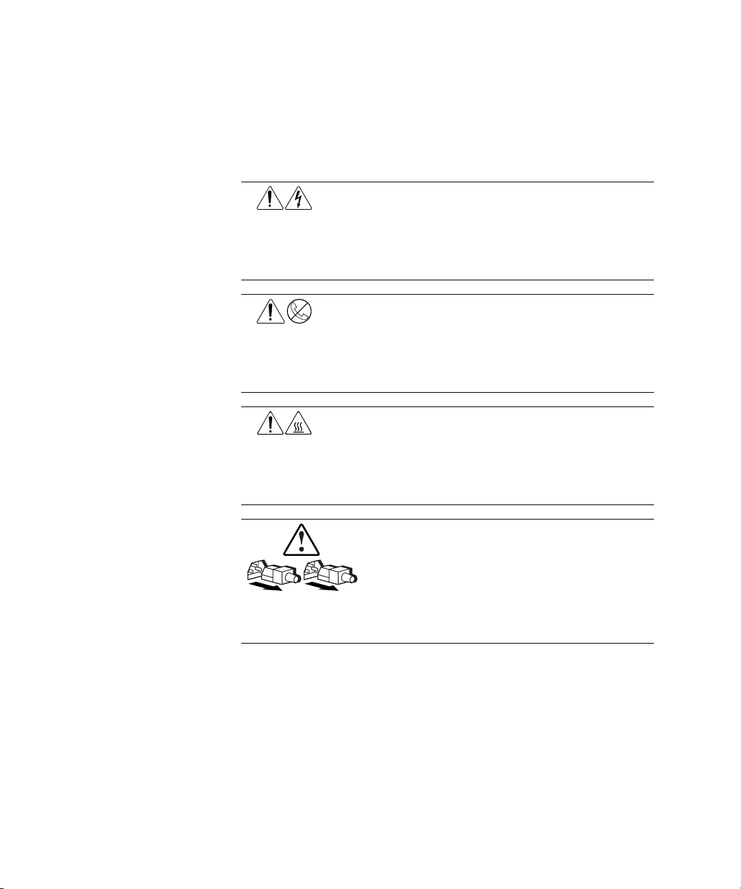
Symbols on Equipment
These icons may be located on equipment in areas where hazardous conditions
may exist.
Any surface or area of the equipment marked with these symbols
indicates the presence of electrical shock hazards. Enclosed area
contains no operator serviceable parts.
WARNING: To reduce the risk of injury from electrical shock hazards,
do not open this enclosure.
Any RJ-45 receptacle marked with these symbols indicates a Network
Interface Connection.
WARNING: To reduce the risk of electrical shock, fire, or damage to
the equipment, do not plug telephone or telecommunications
connectors into this receptacle.
Any surface or area of the equipment marked with these symbols
indicates the presence of a hot surface or hot component. If this
surface is contacted, the potential for injury exists.
WARNING: To reduce the risk of injury from a hot component, allow
the surface to cool before touching.
Power Supplies or Systems marked with these symbols
indicate the equipment is supplied by multiple sources of
power.
WARNING: To reduce the risk of injury from electrical shock,
remove all power cords to completely disconnect power from
the system.
Page 18

Rack Stability
WARNING: To reduce the risk of personal injury or damage to the equipment,
be sure that:
■ The leveling jacks are extended to the floor.
■ The full weight of the rack rests on the leveling jacks.
■ The stabilizing feet are attached to the rack if it is a single rack
installations.
■ The racks are coupled together in multiple rack installations.
■ Only one component is extended at a time. A rack may become unstable if
more than one component is extended for any reason.
Getting Help
If you have a problem and have exhausted the information in this guide, you
can get further information and other help in the following locations.
Compaq Technical Support
About This Guide xix
In North America, call the Compaq Technical Phone Support Center at
1-800-OK-COMPAQ. This service is available 24 hours a day, 7 days a week.
For continuous quality improvement, calls may be recorded or monitored.
Outside North America, call the nearest Compaq Technical Support Phone
Center. Telephone numbers for worldwide Technical Support Centers are
listed on the Compaq website. Access the Compaq website by logging on to
the Internet at
www.compaq.com
Be sure to have the following information available before you call Compaq:
■ Technical support registration number (if applicable)
■ Product serial number
■ Product model name and number
■ Applicable error messages
■ Add-on boards or hardware
■ Third-party hardware or software
■ Operating system type and revision level
Page 19

xx Compaq Parallel Database Cluster Model PDC/O1000 for Oracle8i and Windows 2000 Administrator Guide
Compaq Website
The Compaq website has information on this product as well as the latest
drivers and Flash ROM images. You can access the Compaq website by
logging on to the Internet at
www.compaq.com
Compaq Authorized Reseller
For the name of your nearest Compaq Authorized Reseller:
■ In the United States, call 1-800-345-1518.
■ In Canada, call 1-800-263-5868.
■ Elsewhere, see the Compaq website for locations and telephone
numbers.
Page 20

Chapter 1
Clustering Overview
For many years, companies have depended on clustered computer systems to
fulfill two key requirements: to ensure users can access and process
information that is critical to the ongoing operation of their business, and to
increase the performance and throughput of their computer systems at minimal
cost. These requirements are known as availability and scalability,
respectively.
Historically, these requirements have been fulfilled with clustered systems
built on proprietary technology. Over the years, open systems have
progressively and aggressively moved proprietary technologies into
industry-standard products. Clustering is no exception. Its primary features,
availability and scalability, have been moving into client/server products for
the last few years.
The absorption of clustering technologies into open systems products is
creating less expensive, non-proprietary solutions that deliver levels of
functionality commonly found in traditional clusters. While some uses of the
proprietary solutions will always exist—such as those controlling stock
exchange trading floors and aerospace mission controls—many critical
applications can reach the desired levels of availability and scalability with
non-proprietary client/server-based clustering.
These clustering solutions use industry-standard hardware and software,
thereby providing key clustering features at a lower price than proprietary
clustering systems. Before examining the features and benefits of the
Compaq Parallel Database Cluster Model PDC/O1000 (referred to here as the
PDC/O1000), it is helpful to understand the concepts and terminology of
clustered systems.
Page 21
1-2 Compaq Parallel Database Cluster Model PDC/O1000 for Oracle8i on Windows 2000 Administrator Guide
Clusters Defined
A cluster is an integration of software and hardware products that enables a set
of loosely coupled servers and shared storage subsystem components to
present a single system image to clients and to operate as a single system. As a
cluster, the group of servers and shared storage subsystem components offers a
level of availability and scalability far exceeding that obtained if each cluster
node operated as a standalone server.
The PDC/O1000 uses Oracle8i Parallel Server, which is a parallel database
that can distribute its workload among the cluster nodes.
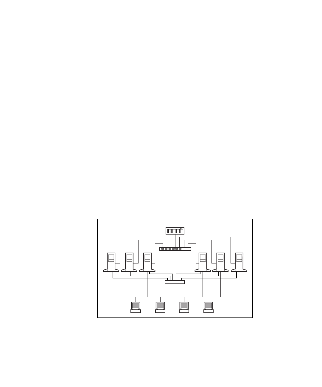
Figure 1-1 shows a PDC/O1000 cluster that contains:
■ Six cluster nodes (ProLiant
■ One Compaq StorageWorks
TM
servers)
TM
RAID Array 4000 (RA4000 Array) or
4100 (RA4100 Array)
■ One Compaq StorageWorks Fibre Channel Storage Hub (Storage Hub),
Compaq StorageWorks FC-AL Switch (FC-AL Switch), or
Compaq StorageWorks Fibre Channel SAN Switch
(Fibre Channel SAN Switch)
■ An Ethernet cluster interconnect
■ A client local area network (LAN)
RA4000/4100 Array
Node 2 Node 4 Node 6
Client LAN
Clients
Node 1Node 3Node 5
Storage Hub/Switch
(Cluster Interconnect)
Switch
Figure 1-1. Example of a six-node Compaq Parallel Database Cluster
Model PDC/
O1000
Page 22

The PDC/O1000 uses non-redundant Fibre Channel Fabric Storage Area
Network (SAN) and non-redundant Fibre Channel Arbitrated Loop (FC-AL)
SAN topologies for its shared storage I/O data paths. These two SAN
topologies support the use of multiple non-redundant fabrics and loops,
respectively. In the example shown in Figure 1-1, the clustered nodes are
connected to the database on the shared storage subsystems through a
non-redundant Fibre Channel Fabric or non-redundant FC-AL. Clients access
the database through the client LAN, and the cluster nodes communicate
across an Ethernet cluster interconnect.
Availability
When computer systems experience outages, the amount of time the system is
unavailable is referred to as downtime. Downtime has several primary causes:
hardware faults, software faults, planned service, operator error, and
environmental factors. Minimizing downtime is a primary goal of a cluster.
Simply defined, availability is the measure of how well a computer system can
continuously deliver services to clients.
Availability is a system-wide endeavor. The hardware, the operating system,
and the applications must be designed for availability. Clustering requires
stability in these components, then couples them in such a way that failure of
one item does not render the system unusable. By using redundant components
and mechanisms that detect and recover from faults, clusters can greatly
increase the availability of applications critical to business operations.
Clustering Overview 1-3
Scalability
Simply defined, scalability is a computer system characteristic that enables
improved performance or throughput when supplementary hardware resources
are added. Scalable systems allow increased throughput by adding components
to an existing system without the expense of adding a new system.
In a stand-alone server configuration, scalable systems allow increased
throughput by adding processors or more memory. In a cluster configuration,
this result is usually obtained by adding cluster nodes.
Not only must the hardware benefit from additional components, but also
software must be constructed in such a way as to take advantage of the
additional processing power. Oracle8i Parallel Server distribute the workload
among the cluster nodes. As more nodes are added to the cluster, cluster-aware
applications can use the parallel features of Oracle8i Parallel Server to
distribute workload among more servers, thereby obtaining greater throughput.
Page 23

1-4 Compaq Parallel Database Cluster Model PDC/O1000 for Oracle8i on Windows 2000 Administrator Guide
Compaq Parallel Database Cluster Overview
As traditional clustering technology has moved into the open systems of
client/server computing, Compaq has provided innovative, customer-focused
solutions. The PDC/O1000 moves client/server computing one step closer to
the capabilities found in expensive, proprietary cluster solutions, at a fraction
of the cost.
The PDC/O1000 combines the Microsoft Windows 2000 Advanced Server
operating system and the industry-leading Oracle8i Parallel Server with
award-winning Compaq ProLiant servers and shared storage subsystems.
Together, these hardware and software components provide improved
performance through a truly scalable parallel application and improved
availability using clustering software that rapidly recovers from detectable
faults. These components also provide improved availability through
concurrent multinode database access using Oracle8i Parallel Server.
Page 24

Chapter 2
Architecture
The Compaq Parallel Database Cluster Model PDC/O1000 (referred to here as
the PDC/O1000) is an integration of a number of different hardware and
software products. This chapter discusses how each of the hardware products
plays a role in bringing a complete clustering solution to your computing
environment.
The hardware products include:
■ Compaq Proliant servers
■ Shared storage components
G Compaq StorageWorks RAID Array 4100s (RA4100 Arrays) or
Compaq StorageWorks RAID Array 4000s (RA4000 Arrays)
G Compaq StorageWorks RAID Array 4000 Controller (RA4000
Array Controller) installed in each RA4000 Array or RA4100 Array
G Compaq StorageWorks Fibre Channel SAN Switch (Fibre Channel
SAN Switch) for each non-redundant Fibre Channel Fabric
G Compaq StorageWorks Storage Hub (Storage Hub) or
Compaq StorageWorks FC-AL Switch (FC-AL Switch) for each
non-redundant Fibre Channel Arbitrated Loop
G Compaq StorageWorks 64-bit/66 MHz Fibre Channel Host Adapter
or Compaq StorageWorks Fibre Channel Host Adapter/P (Fibre Host
Adapter) installed in each server
Page 25

2-2 Compaq Parallel Database Cluster Model PDC/O1000 for Oracle8i and Windows 2000 Administrator Guide
Gigabit Interface Converter-Shortwave (GBIC-SW) modules
G
G Fibre Channel cables
■ Cluster interconnect components
G Ethernet NIC adapters
G Ethernet cables
G Ethernet switches or hubs
The software products include:
■ Microsoft Windows 2000 Advanced Server with Service Pack 1 or later
■ Compaq drivers and utilities
■ Oracle8i Enterprise Edition with the Oracle8i Parallel Server Option
Refer to Chapter 3, “Cluster Software Components,” for a description of the
software products used with the PDC/O1000.
Compaq ProLiant Servers
A primary component of any cluster is the server. Each PDC/O1000 consists
of two or more cluster nodes. Each node is a Compaq ProLiant server.
With some exceptions, all nodes in a PDC/O1000 cluster must be identical in
model. In addition, all components common to all nodes in a cluster, such as
memory, number of CPUs, and the interconnect adapters, must be identical
and identically configured.
NOTE: Certain restrictions apply to the server models and server configurations that are
supported by the PDC/O1000. For a current list of PDC-certified servers and details on
supported configurations, refer to the Compaq Parallel Database Cluster Model
PDC/O1000 for Windows 2000 Certification Matrix at
www.compaq.com/solutions/enterprise/ha-pdc.html
Page 26

High-Availability Features of ProLiant Servers
In addition to the increased application and data availability enabled by
clustering, ProLiant servers include many reliability features that provide a
solid foundation for effective clustered server solutions. The PDC/O1000 is
based on ProLiant servers, most of which offer excellent reliability through
redundant power supplies, redundant cooling fans, and Error Checking and
Correcting (ECC) memory. The high-availability features of ProLiant servers
are a critical foundation of Compaq clustering products. Table 2-1 lists the
high-availability features found in many ProLiant servers.
Table 2-1
High-Availability Components of ProLiant Servers
Hot-pluggable hard drives Redundant power supplies
Digital Linear Tape (DLT) Array (optional) ECC-protected processor-memory bus
Uninterruptible power supplies (optional) Redundant processor power modules
ECC memory PCI Hot Plug slots (in some servers)
Offline backup processor Redundant cooling fans
Architectur e 2-3
Shared Storage Components
The PDC/O1000 is based on a cluster architecture known as “shared storage
clustering,” in which clustered nodes share access to a common set of shared
disk drives. For the PDC/O1000, the shared storage includes these hardware
components:
■ RA4000 Arrays or RA4100 Arrays
■ One RA4000 Array Controller in each RA4000 Array or RA4100 Array
■ One Fibre Channel SAN Switch for each non-redundant Fibre Channel
Fabric
■ One Storage Hub or FC-AL Switch for each non-redundant Fibre
Channel Arbitrated Loop
■ Fibre Host Adapters
■ GBIC-SW modules
■ Fibre Channel cables
Page 27

2-4 Compaq Parallel Database Cluster Model PDC/O1000 for Oracle8i and Windows 2000 Administrator Guide
RA4000 Array
The RA4000 Array is one shared storage solution for the PDC/O1000. Each
non-redundant Fibre Channel Fabric or non-redundant Fibre Channel
Arbitrated Loop (FC-AL) can contain one or more RA4000 Arrays. Each
RA4000 Array contains one single-port RA4000 Array Controller. The array
controller connects the RA4000 Array to one Storage Hub, FC-AL Switch, or
Fibre Channel SAN Switch, which in turn is connected to one Fibre Host
Adapter in each cluster node.
The RA4000 Array can hold up to twelve 1-inch or eight 1.6-inch Wide-Ultra
SCSI drives. The drives must be mounted on Compaq hot-pluggable drive
trays. SCSI IDs are assigned automatically according to their drive location,
allowing 1-inch and 1.6-inch drives to be intermixed within the same RA4000
Array.
The RA4000 Array comes in either a rack-mountable or a tower model.
For more information about the RA4000 Array, refer to the
Compaq StorageWorks RAID Array 4000 User Guide.
RA4100 Array
The RA4100 Array is another shared storage solution for the PDC/O1000.
Each non-redundant Fibre Channel Fabric or non-redundant Fibre Channel
Arbitrated Loop (FC-AL) can contain one or more RA4100 Arrays. Each
RA4100 Array contains one single-port RA4000 Array Controller. The array
controller connects the RA4100 Array to one Storage Hub, FC-AL Switch, or
Fibre Channel SAN Switch, which in turn is connected to one Fibre Host
Adapter in each cluster node.
The RA4100 Array can hold up to twelve 1-inch Compaq Hot Plug Ultra2
Disk Drives. The drives must be mounted on Compaq hot-pluggable drive
trays. SCSI IDs are assigned automatically according to their drive location.
The RA4100 Array comes in a rack-mountable model.
For more information about the RA4100 Array, refer to the
Compaq StorageWorks RAID Array 4100 User Guide.
Page 28

RA4000 Array Controller
One single-port RA4000 Array Controller is installed in each RA4000 Array
or RA4100 Array. If the array controller fails, the cluster nodes cannot access
the shared storage disks in that array.
From the perspective of the cluster nodes, the RA4000 Array Controller is
simply another device connected to one of the cluster’s I/O paths.
Consequently, each node sends its I/O requests to the RA4000 Array
Controller just as it would to any SCSI device. The RA4000 Array Controller
receives the I/O requests from the nodes and directs them to the shared storage
disks to which it has been configured. Because the array controller processes
the I/O requests, the cluster nodes are not burdened with the I/O processing
tasks associated with reading and writing data to multiple shared storage
devices.
For more information about the RA4000 Array Controller, refer to
the Compaq StorageWorks RAID Array 4000 User Guide or the
Compaq StorageWorks RAID Array 4100 User Guide.
Fibre Channel SAN Switch
Architectur e 2-5
One Fibre Channel SAN Switch is installed between cluster nodes and shared
storage arrays in a PDC/O1000 cluster to create a non-redundant Fibre
Channel Fabric.
An 8-port or 16-port Fibre Channel SAN Switch can be used. The choice of an
8-port or 16-port Fibre Channel SAN Switch is determined by your hardware
requirements. For example, a non-redundant Fibre Channel Fabric with four
Fibre Host Adapters and five or more RA4000/RA4100 Arrays would require
a 16-port Fibre Channel SAN Switch.
The Fibre Channel SAN Switch provides full 100 MBps bandwidth on every
port. Adding new devices to ports on the Fibre Channel SAN Switch increases
the aggregate bandwidth.
Fibre Channel SAN Switch is used to connect one Fibre Host Adapter in each
cluster node to the array controller in the RA4000/RA4100 Arrays. The Fibre
Host Adapter in each node, the Fibre Channel SAN Switch, and the
RA4000/RA41000 Arrays to which they are connected belong to the same
non-redundant Fibre Channel Fabric.
Page 29

2-6 Compaq Parallel Database Cluster Model PDC/O1000 for Oracle8i and Windows 2000 Administrator Guide
For further information, refer to these manuals provided with the Fibre
Channel SAN Switch:
■ Compaq StorageWorks Fibre Channel SAN Switch 8 Installation and
Hardware Guide
■ Compaq StorageWorks Fibre Channel SAN Switch 16 Installation and
Hardware Guide
■ Compaq StorageWorks Fibre Channel SAN Switch Management Guide
provided with the Fibre Channel SAN Switch
Storage Hub
One Storage Hub can be installed between cluster nodes and shared storage
arrays in a PDC/O1000 cluster to create a non-redundant Fibre Channel
Arbitrated Loop (FC-AL).
The Storage Hub is one method for connecting one Fibre Host Adapter in each
node with the array controller in the RA4000/RA4100 Array. The Fibre Host
Adapter in each node, the Storage Hub, and the RA4000/RA41000 Arrays to
which they are connected belong to the same non-redundant FC-AL.
On the Storage Hub, one port is used by a Fibre Host Adapter in each node
and one port is used to connect to the array controller in each
RA4000/RA4100 Array.
The PDC/O1000 allows the use of either the Storage Hub 7 (with 7 ports) or
the Storage Hub 12 (with 12 ports). Using the Storage Hub 7 limits the total
number of nodes and RA4000/RA4100 Arrays you can install in a
non-redundant. For example, a non-redundant FC-AL with four Fibre Host
Adapters and four or more RA4000/RA4100 Arrays requires a Storage Hub
with at least 8 ports (a Storage Hub 12). In your selection of a Storage Hub,
you should also consider the likelihood of cluster growth.
Refer to the Compaq StorageWorks Fibre Channel Storage Hub 7 Installation
Guide and the Compaq StorageWorks Fibre Channel Storage Hub 12
Installation Guide for further information about these products.
Page 30
FC-AL Switch
One FC-AL Switch can also be installed between cluster nodes and shared
storage arrays in a PDC/O1000 cluster to create a non-redundant Fibre
Channel Arbitrated Loop (FC-AL).
The FC-AL Switch is another device for connecting one Fibre Host Adapter in
each node with the array controller in the RA4000/RA4100 Array. The Fibre
Host Adapter in each node, the FC-AL Switch, and the RA4000/RA41000
Arrays to which they are connected belong to the same non-redundant FC-AL.
The FC-AL Switch 8 supports eight ports. With the addition of the 3-port
Expansion Module (PEM), the switch supports 11 ports.
For further information, refer to the Compaq StorageWorks Fibre Channel
Arbitrated Loop Switch (FC-AL Switch) User Guide.
Fibre Host Adapters
Fibre Host Adapters are the interface between the cluster nodes (servers) and
the RA4000/RA4100 Arrays to which they are connected. As Figure 2-1
shows, a Fibre Channel cable runs from one Fibre Host Adapter in each cluster
node to a port on the Fibre Channel SAN Switch, FC-AL Switch, or
Storage Hub.
Architectur e 2-7
RA4000/4100
Array
Fibre
Host Adapter
ProLiant
Server
Figure 2-1. Fibre Host Adapters in a two-node PDC/O1000 cluster
Node 1
Client LAN
RA4000/4100
Array
Storage Hub/Switch
Switch
(Cluster Interconnect)
RA4000/4100
Array
Node 2
Fibre
Host Adapter
ProLiant
Server
Page 31

2-8 Compaq Parallel Database Cluster Model PDC/O1000 for Oracle8i and Windows 2000 Administrator Guide
Each non-redundant Fibre Channel Fabric or non-redundant FC-AL contains
one dedicated Fibre Host Adapter in every cluster node. Across nodes, Fibre
Host Adapters for the same Fibre Channel Fabric or FC-AL must be installed
in the same server slot and connected to the same Fibre Channel SAN Switch,
FC-AL Switch, or Storage Hub.
If the PDC/O1000 cluster contains multiple non-redundant Fibre Channel
Fabrics or FC-ALs, then each Fibre Channel Fabric or FC-AL has its own
dedicated Fibre Host Adapter in each cluster node.
For more information about the Fibre Channel Host Adapter, refer to the
Compaq StorageWorks Fibre Channel Host Bus Adapter Installation Guide or
the Compaq StorageWorks 64-Bit/66-MHz Fibre Channel Host Adapter
Installation Guide.
Gigabit Interface Converter-Shortwave Modules
A Gigabit Interface Converter-Shortwave (GBIC-SW) module must be
installed at both ends of a Fibre Channel cable. One GBIC-SW module is
installed into each Fibre Host Adapter, each active port on a Fibre Channel
SAN Switch, FC-AL Switch, or Storage Hub, and each RA4000 Array
Controller.
GBIC-SW modules provide 100 MB/second performance. Fibre Channel
cables connected to these modules can be up to 500 meters in length.
Fibre Channel Cables
Shortwave (multi-mode) fibre optic Fibre Channel cables are used to connect
the Fibre Host Adapters, Storage Hubs or FC-AL Switches, and
RA4000/RA4100 Arrays in a PDC/O1000 cluster.
Page 32

Availability Features of the Shared Storage Components
An important part of a high-availability system is the ability to improve data
availability, traditionally accomplished by implementing RAID technology.
Hardware RAID is an important part of the RA4000/RA4100 Array storage
subsystem. RAID is implemented on the RA4000 Array Controller in the
RA4000/RA4100 Array. The RA4000/RA4100 Array also accepts redundant,
hot-pluggable power supplies and a hot-pluggable fan module.
The RA4000 Array Controller supports pre-failure notification on hard drives
and provides an Array Accelerator made with ECC memory. The Array
Accelerator is backed with onboard rechargeable batteries, ensuring that the
data temporarily held (cached) is safe even with equipment failure or power
outage. For a complete list of features and accompanying descriptions, refer to
the Compaq StorageWorks RAID Array 4000 User Guide or the
Compaq StorageWorks RAID Array 4100 User Guide.
I/O Path Configurations in a
Non-Redundant Fibre Channel Fabric
Architectur e 2-9
Overview of Fibre Channel Fabric SAN Topology
Fibre Channel standards define a multi-layered architecture for moving data
across the storage area network (SAN). This layered architecture can be
implemented using the Fibre Channel Fabric or the Fibre Channel Arbitrated
Loop (FC-AL) topology. The PDC/O1000 supports both topologies.
Fibre Channel SAN Switches provide full 100 MBps bandwidth per switch
port. Whereas the introduction of new devices to a FC-AL Storage Hub further
divides its shared bandwidth, adding new devices to a Fibre Channel SAN
Switch increases the aggregate bandwidth.
Page 33

2-10 Compaq Parallel Database Cluster Model PDC/O1000 for Oracle8i and Windows 2000 Administrator Guide
Non-Redundant Fibre Channel Fabric
The PDC/O1000 supports non-redundant Fibre Channel Fabrics. A
non-redundant Fibre Channel Fabric provides one I/O path between each
cluster node and its Fibre Channel SAN Switch and one I/O data path between
the Fibre Channel SAN Switch and each of its RA4000/RA4100 Arrays.
The switching hardware used distinguishes a non-redundant Fibre Channel
Fabric from a non-redundant FC-AL. A non-redundant Fibre Channel Fabric
uses one Fibre Channel SAN Switch installed between one Fibre Host Adapter
in each cluster node and the RA4000 Array Controller in each
RA4000/RA4100 Array for that fabric. These hardware components cannot be
shared by other non-redundant Fibre Channel Fabrics or non-redundant
FC-ALs in the PDC/O1000 cluster.
Each non-redundant Fibre Channel Fabric consists of the following hardware:
■ One Fibre Host Adapter in each node
■ One Fibre Channel SAN Switch
■ One or more RA4000/RA4100 Arrays, each containing one single-port
RA4000 Array Controller
■ A GBIC-SW module installed in each Fibre Host Adapter, each active
port on the Fibre Channel SAN Switch, and each array controller
■ Fibre Channel cables used to connect the Fibre Host Adapter in each
node to the Fibre Channel SAN Switch and the Fibre Channel SAN
Switch to each array controller
Page 34

Architectur e 2-11
Figure 2-2 shows a two-node PDC/O1000 with one non-redundant Fibre
Channel Fabric.
Fibre
Host Adapter
ProLiant
Server
RA4000/4100
Array
Node 1
Client LAN
RA4000/4100
Array
Fibre Channel
SAN Switch
Switch
(Cluster Interconnect)
RA4000/4100
Figure 2-2. Two-node PDC/O1000 cluster with one non-redundant Fibre
Channel Fabric
Using Multiple Non-Redundant Fibre Channel
Fabrics
The PDC/O1000 supports the use of multiple non-redundant Fibre Channel
Fabrics within the same cluster. Physically, this means that within each cluster
node, multiple Fibre Host Adapters are used to connect the nodes to different
sets of RA4000/RA4100 Arrays.
Array
Node 2
Fibre
Host Adapter
ProLiant
Server
NOTE: The PDC/O1000 supports the mixing of non-redundant Fibre Channel Fabrics and
non-redundant FC-ALs in the same cluster.
You would install additional non-redundant Fibre Channel Fabrics in a
PDC/O1000 cluster to:
■ Increase the amount of shared storage available to the cluster’s servers
when the Fibre Channel SAN Switch in your first Fibre Channel Fabric
is filled to capacity. With just one Fibre Channel Fabric present, your
shared storage resources are restricted by the number of ports available
on its Fibre Channel SAN Switch.
■ Increase the PDC/O1000 cluster’s I/O performance.
Page 35

2-12 Compaq Parallel Database Cluster Model PDC/O1000 for Oracle8i and Windows 2000 Administrator Guide
Adding a second non-redundant Fibre Channel Fabric to the PDC/O1000
involves duplicating the hardware components used in the first Fibre Channel
Fabric.
The maximum number of non-redundant Fibre Channel Fabrics you can install
in a PDC/O1000 is restricted by the number of Fibre Host Adapters your
Compaq ProLiant servers support. Refer to the Compaq ProLiant server
documentation for this information.
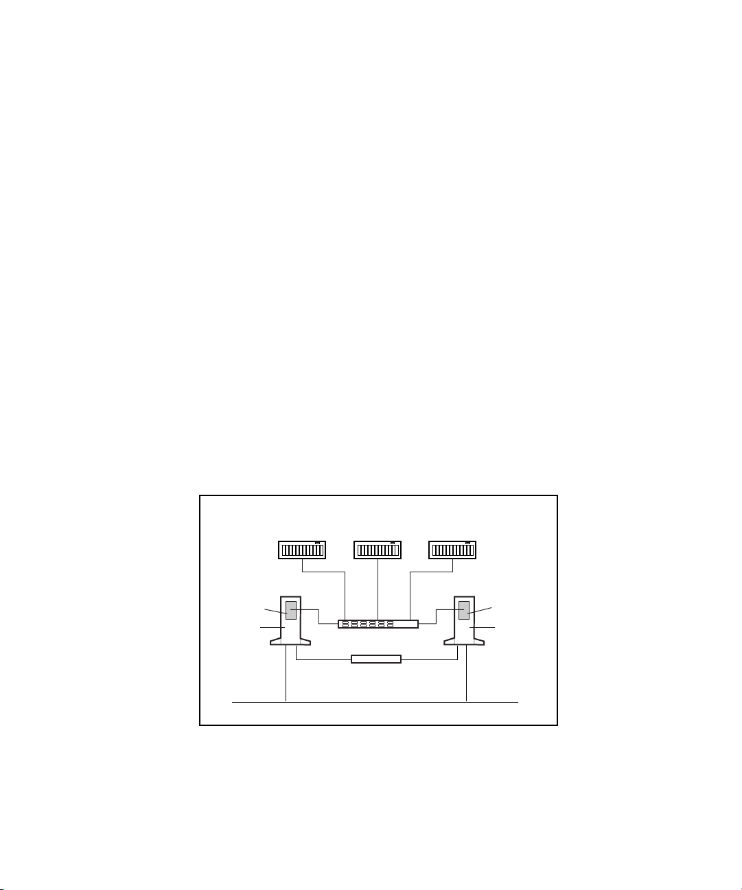
Figure 2-3 shows a four-node PDC/O1000 cluster with two non-redundant
Fibre Channel Fabrics. Each Fibre Channel Fabric has its own Fibre Host
Adapter in every node, one Fibre Channel SAN Switch, and one or more
RA4000/RA4100 Arrays. In Figure 2-3, the hardware components that
constitute the second Fibre Channel Fabric are shaded.
RA4000/4100
Arrays (8)
Fibre
Host Adapters
RA4000/4100
Arrays (4)
Fibre Channel
SAN Switches
Fibre
Host Adapters
Figure 2-3. PDC/O1000 cluster with two non-redundant Fibre Channel Fabrics
In Figure 2-3, the original non-redundant Fibre Channel Fabric connects to
eight RA4000/RA4100 Arrays. The second Fibre Channel Fabric connects to
four RA4000/RA4100 Arrays.
Page 36

Maximum Distances Between Cluster Nodes and
Shared Storage Subsystem Components in a
Non-Redundant Fibre Channel Fabric
By using standard short-wave Fibre Channel cables and GBIC-SW modules,
an RA4000/RA4100 Array can be placed up to 500 meters from the Fibre
Channel SAN Switch, and the Fibre Channel SAN Switch can be placed up to
500 meters from the Fibre Host Adapter in each cluster node. See Figure 2-4.
RA4000/4100 Array
Architectur e 2-13
500 m
Node 1Node 3
500 m
Fibre Channel
SAN Switch
Figure 2-4. Maximum distances between cluster nodes and shared
storage components in a non-redundant Fibre Channel Fabric
500 m
Node 2 Node 4
500 m
I/O Data Paths for a Non-Redundant Fibre Channel
Fabric
The shared storage components in a non-redundant Fibre Channel Fabric use
two distinct I/O data paths, separated by the Fibre Channel SAN Switch:
■ One path runs from the Fibre Host Adapter in each node to the Fibre
Channel SAN Switch.
■ Another path runs from the Fibre Channel SAN Switch to the RA4000
Array Controller in each RA4000/RA4100 Array of that Fibre Channel
Fabric.
500 m
Page 37

2-14 Compaq Parallel Database Cluster Model PDC/O1000 for Oracle8i and Windows 2000 Administrator Guide
Fibre Host Adapter-to-Fibre Channel SAN Switch Paths
Figure 2-5 highlights the I/O data paths that run between the Fibre Host
Adapter in each cluster node and the Fibre Channel SAN Switch. There is one
I/O path for each Fibre Host Adapter.
Client LAN
Fibre
Host Adapters
Switch
(Cluster Interconnect)
ProLiant
Servers
Fibre Channel
SAN Switch
RA4000/4100 Array
Figure 2-5. Fibre Host Adapter-to-Fibre Channel SAN Switch I/O data paths
Fibre
Host Adapters
ProLiant
Servers
If one of these connections experiences a fault, the connections from the other
nodes ensure continued access to the database. The fault results in the eviction
of the cluster node with the failed connection. All network clients accessing
the database through that node must reconnect through another cluster node.
The effect of this failure is relatively minor. It affects only those users who are
connected to the database through the affected node. The duration of
downtime includes the time to detect the failure, the time to reconfigure from
the failure, and the time required for the network clients to reconnect to the
database through another node.
Note that Compaq Insight Manager
TM
monitors the health of each
RA4000/RA4100 Array. If any part of the I/O data path disrupts a node’s
access to an RA4000/RA4100 Array, the status of the array controller in that
RA4000/RA4100 Array changes to “Failed” and the condition is red. The red
condition is reported to higher-level Insight Manager screens, and eventually
to the device list. Refer to the Compaq Insight Manager Guide for details.
Page 38

Architectur e 2-15
Fibre Channel SAN Switch-to-Array Controller Paths
Figure 2-6 highlights the I/O data path that runs between the Fibre Channel
SAN Switch and the RA4000 Array Controller in each RA4000/RA4100
Array of a Fibre Channel Fabric. There is one path for each array controller.
Client LAN
Fibre
Host Adapters
Switch
(Cluster Interconnect)
ProLiant
Servers
Fibre Channel
SAN Switch
RA4000/4100 Array
Figure 2-6. Fibre Channel SAN Switch-to-array controller I/O data path
Fibre
Host Adapters
ProLiant
Servers
If this connection experiences a fault, the affected RA4000/RA4100 Array
cannot be accessed from any of the cluster nodes. Because the nodes do not
have access to the affected RA4000/RA4100 Array, users cannot reach the
data contained on that array. The data, however, is unharmed and remains
safely stored on the physical disks inside the RA4000/RA4100 Array.
As with the Fibre Host Adapter-to-Fibre Channel SAN Switch data path,
Compaq Insight Manager detects this fault, changes the affected
RA4000/RA4100 Array’s status to “Failed,” and changes its condition to red.
Page 39

2-16 Compaq Parallel Database Cluster Model PDC/O1000 for Oracle8i and Windows 2000 Administrator Guide
I/O Path Configurations in a
Non-Redundant Fibre Channel Arbitrated
Loop
Overview of FC-AL SAN Topology
Fibre Channel standards define a multi-layered architecture for moving data
across the storage area network (SAN). This layered architecture can be
implemented using the Fibre Channel Fabric SAN or the Fibre Channel
Arbitrated Loop (FC-AL) SAN topology. The PDC/O1000 supports both
topologies.
When you use a Storage Hub to connect Fibre Host Adapters with
RA4000/RA4100 Arrays, the FC-AL SAN acts as a shared gigabit transport
with a total 100 MB/second bandwidth divided among all Storage Hub ports.
The functional bandwidth available to any one device on a Storage Hub port is
determined by the total population on the segment and the level of activity of
devices on other ports. The more devices used, the less bandwidth that is
available for each port.
When you use a FC-AL Switch, the FC-AL SAN supports multiple
100 MB/second point-to-point connections in parallel. The FC-AL Switch
provides multiple dedicated, non-blocking connections between Fibre Host
Adapters and array controllers (as contrasted with the shared connections on a
Storage Hub). The FC-AL Switch also eliminates the shared bandwidth speed
limitations of the Storage Hub.
Non-Redundant Fibre Channel Arbitrated Loop
The PDC/O1000 supports non-redundant Fibre Channel Arbitrated Loops
(FC-ALs). A non-redundant FC-AL provides one I/O path between each
cluster node and its Storage Hub or FC-AL Switch and one I/O data path
between the Storage Hub or FC-AL Switch and the array controller in each of
its RA4000/RA4100 Arrays.
The switching hardware used distinguishes a non-redundant FC-AL from a
non-redundant Fibre Channel Fabric. A non-redundant FC-AL uses one
Storage Hub or FC-AL Switch installed between one Fibre Host Adapter in
each cluster node and the RA4000 Array Controller in each RA4000/RA4100
Array for that loop. These hardware components cannot be shared by other
non-redundant FC-ALs or non-redundant Fibre Channel Fabrics in the
PDC/O1000 cluster.
Page 40

Architectur e 2-17
Each non-redundant FC-AL consists of the following hardware:
■ One Fibre Host Adapter in each node
■ One Storage Hub or FC-AL Switch
■ One or more RA4000/RA4100 Arrays, each containing one single-port
RA4000 Array Controller
■ A GBIC-SW module installed in each Fibre Host Adapter, each active
port on the Storage Hub or FC-AL Switch, and each array controller
■ Fibre Channel cables used to connect the Fibre Host Adapter in each
node to the Storage Hub or FC-AL Switch and the Storage Hub or
FC-AL Switch to each array controller
Figure 2-7 shows a two-node PDC/O1000 with one non-redundant FC-AL.
Fibre
Host Adapter
ProLiant
Server
RA4000/4100
Array
Node 1
Client LAN
RA4000/4100
Array
Storage Hub/
FC-AL Switch
Switch
(Cluster Interconnect)
RA4000/4100
Array
Node 2
Fibre
Host Adapter
ProLiant
Server
Figure 2-7. Two-node PDC/O1000 cluster with one non-redundant FC-AL
Page 41

2-18 Compaq Parallel Database Cluster Model PDC/O1000 for Oracle8i and Windows 2000 Administrator Guide
Using Multiple Non-Redundant Fibre Channel Arbitrated Loops
The PDC/O1000 supports the use of multiple non-redundant FC-ALs within
the same cluster. Physically, this means that within each cluster node, multiple
Fibre Host Adapters are used to connect the nodes to different sets of
RA4000/RA4100 Arrays.
NOTE: The PDC/O1000 supports the mixing of non-redundant FC-ALs and non-redundant
Fibre Channel Fabrics in the same cluster.
You would install additional non-redundant FC-ALs in a PDC/O1000
cluster to:
■ Increase the amount of shared storage available to the cluster’s servers
when the Storage Hub or FC-AL Switch in your first FC-AL is filled to
capacity. With just one FC-AL present, your shared storage resources
are restricted by the number of ports available on its Storage Hub or
FC-AL Switch.
■ Increase the PDC/O1000 cluster’s I/O performance.
Adding a second non-redundant FC-AL to the PDC/O1000 involves
duplicating the hardware components used in the first FC-AL.
The maximum number of non-redundant FC-ALs you can install in a
PDC/O1000 is restricted by the number of Fibre Host Adapters your
Compaq ProLiant servers support. Refer to the Compaq ProLiant server
documentation for this information.
Page 42

Architectur e 2-19
Figure 2-8 shows a four-node PDC/O1000 cluster with two non-redundant
FC-ALs. Each FC-AL has its own Fibre Host Adapter in every node, one
Storage Hub or FC-AL Switch, and one or more RA4000/RA4100 Arrays. In
Figure 2-8, the hardware components that constitute the second non-redundant
FC-AL are shaded.
RA4000/4100
Arrays (8)
Fibre
Host Adapters
RA4000/4100
Arrays (4)
Storage Hubs/
FC-AL Switches
Fibre
Host Adapters
Figure 2-8. PDC/O1000 cluster with two non-redundant FC-ALs
In Figure 2-8, the original non-redundant FC-AL connects to eight
RA4000/RA4100 Arrays. The second non-redundant FC-AL connects to four
RA4000/RA4100 Arrays.
Page 43

2-20 Compaq Parallel Database Cluster Model PDC/O1000 for Oracle8i and Windows 2000 Administrator Guide
Maximum Distances Between Cluster Nodes and
Shared Storage Subsystem Components in a
Non-Redundant FC-AL
By using standard short-wave Fibre Channel cables and GBIC-SW modules,
an RA4000/RA4100 Array can be placed up to 500 meters from the Storage
Hub or FC-AL Switch, and the Storage Hub or FC-AL Switch can be placed
up to 500 meters from the Fibre Host Adapter in each cluster node. See
Figure 2-9.
RA4000/4100 Array
500 m
Node 1Node 3
500 m
Storage Hub/FC-AL Switch
Figure 2-9. Maximum distances between cluster nodes and shared
storage components in a non-redundant FC-AL
I/O Data Paths for a Non-Redundant FC-AL
The shared storage components in a non-redundant FC-AL use two distinct
I/O data paths, separated by the Storage Hub or FC-AL Switch:
■ One path runs from the Fibre Host Adapter in each node to the Storage
Hub or FC-AL Switch.
■ Another path runs from the Storage Hub or FC-AL Switch to the
RA4000 Array Controller in each RA4000/RA4100 Array of that
non-redundant FC-AL.
500 m
Node 2 Node 4
500 m
500 m
Page 44

Architectur e 2-21
Fibre Host Adapter-to-Storage Hub/FC-AL
Switch Paths
Figure 2-10 highlights the I/O data paths that run between the Fibre Host
Adapter in each cluster node and the Storage Hub or FC-AL Switch. There is
one I/O path for each Fibre Host Adapter.
Client LAN
Fibre
Host Adapters
Switch
(Cluster Interconnect)
ProLiant
Servers
Storage Hub/FC-AL Switch
RA4000/4100 Array
Figure 2-10. Fibre Host Adapter-to-Storage Hub/FC-AL Switch I/O data paths
Fibre
Host Adapters
ProLiant
Servers
If one of these connections experiences a fault, the connections from the other
nodes ensure continued access to the database. The fault results in the eviction
of the cluster node with the failed connection. All network clients accessing
the database through that node must reconnect through another cluster node.
The effect of this failure is relatively minor. It affects only those users who are
connected to the database through the affected node. The duration of
downtime includes the time to detect the failure, the time to reconfigure from
the failure, and the time required for the network clients to reconnect to the
database through another node.
Note that Compaq Insight Manager monitors the health of each
RA4000/RA4100 Array. If any part of the I/O data path disrupts a node’s
access to an RA4000/RA4100 Array, the status of the array controller in that
RA4000/RA4100 Array changes to “Failed” and the condition is red. The red
condition is reported to higher-level Insight Manager screens, and eventually
to the device list. Refer to the Compaq Insight Manager Guide for details.
Page 45

2-22 Compaq Parallel Database Cluster Model PDC/O1000 for Oracle8i and Windows 2000 Administrator Guide
Storage Hub/FC-AL Switch-to-Array Controller Paths
Figure 2-11 highlights the I/O data path that runs between the Storage Hub or
FC-AL Switch and the RA4000 Array Controller in each RA4000/RA4100
Array of the FC-AL. There is one path for each array controller.
Client LAN
Fibre
Host Adapters
Switch
(Cluster Interconnect)
ProLiant
Servers
Storage Hub/FC-AL Switch
RA4000/4100 Array
Figure 2-11. Storage Hub/FC-AL Switch-to-array controller I/O data path
Fibre
Host Adapters
ProLiant
Servers
If this connection experiences a fault, the affected RA4000/RA4100 Array
cannot be accessed from any of the cluster nodes. Because the nodes do not
have access to the affected RA4000/RA4100 Array, users cannot reach the
data contained on that array. The data, however, is unharmed and remains
safely stored on the physical disks inside the RA4000/RA4100 Array.
As with the Fibre Host Adapter-to-Storage Hub/FC-AL Switch data path,
Compaq Insight Manager detects this fault, changes the affected
RA4000/RA4100 Array’s status to “Failed,” and changes its condition to red.
Page 46

Cluster Interconnect Options
The cluster interconnect is the data path over which all of the nodes in a
cluster communicate. The nodes use the cluster interconnect data path to:
■ Communicate individual resource and overall cluster status.
■ Send and receive heartbeat signals.
■ Coordinate database locks through the Oracle Integrated Distributed
Lock Manager.
NOTE: Several terms for cluster interconnect are used throughout the industry. Others
are: private LAN, private interconnect, system area network (SAN), and private network.
Throughout this guide, the term cluster interconnect is used.
A PDC/O1000 cluster running Oracle8i Parallel Server uses an Ethernet
cluster interconnect. The Ethernet cluster interconnect can be redundant or
non-redundant. A redundant cluster interconnect is recommended because it
uses redundant hardware to provide fault tolerance along the entire cluster
interconnect path.
Ethernet Cluster Interconnect
Architectur e 2-23
IMPORTANT: The cluster management software for the Ethernet cluster interconnect
requires the use of TCP/IP. When configuring the Ethernet cluster interconnect, be sure to
enable TCP/IP.
NOTE: Refer to the technical white paper Supported Ethernet Interconnects for Compaq
Parallel Database Clusters Using Oracle Parallel Server (ECG062/0299) for detailed
information about configuring redundant and non-redundant Ethernet cluster
interconnects. This document is available at
www.compaq.com/support/techpubs/whitepapers
Page 47

2-24 Compaq Parallel Database Cluster Model PDC/O1000 for Oracle8i and Windows 2000 Administrator Guide
Non-Redundant Ethernet Cluster Interconnect Components
The following components are used in a non-redundant Ethernet cluster
interconnect:
■ One Ethernet adapter in each cluster node
■ Ethernet cables and a switch or hub
G For two-node PDC/O1000 clusters, you can either use one Ethernet
crossover cable or one 100-Mbit/second Ethernet switch or hub and
standard Ethernet cables to connect the two servers.
G For PDC/O1000 clusters with three or more nodes, you use one
100-Mbit/second Ethernet switch and standard Ethernet cables to
connect the servers.
Redundant Ethernet Cluster Interconnect Components
The following components are used in a redundant Ethernet cluster
interconnect:
■ Two Ethernet adapters in each cluster node
■ Ethernet cables and switches or hubs
G For two-node PDC/O1000 clusters, you can use two
100-Mbit/second Ethernet switches or hubs with cables to connect
the servers.
G For PDC/O1000 clusters with three or more nodes, you use two
100-Mbit/second Ethernet switches connected by Ethernet cables to
a separate Ethernet adapter in each server.
NOTE: In a redundant Ethernet cluster configuration, one Ethernet crossover cable must
be installed between the two Ethernet switches or hubs that are dedicated to the cluster
interconnect.
Ethernet Cluster Interconnect Adapters
To implement the Ethernet cluster interconnect, each cluster node must be
equipped with Ethernet adapters capable of 100-Mbit/second transfer rates.
Some adapters may be capable of operating at both 10-Mbit/second and
100-Mbit/second; however, Ethernet adapters used for the cluster interconnect
must run at 100-Mbit/second.
Page 48

Architectur e 2-25
The Ethernet adapters must have passed Windows 2000 Advanced HCT
certification.
NOTE: If you are using dual-port Ethernet adapters in a non-redundant Ethernet cluster
interconnect, you can use one port for the Ethernet cluster interconnect and the second
port for the client LAN. Refer to the technical white paper Supported Ethernet
Interconnects for Compaq Parallel Database Clusters Using Oracle Parallel Server for
detailed information about configuring redundant Ethernet cluster interconnects. This
document is available at
www.compaq.com/support/techpubs/whitepapers
For detailed information about installing an Ethernet cluster interconnect; see
Chapter 5, “Installation and Configuration.”
Ethernet Switch
IMPORTANT: The Ethernet switch or switches used with the Ethernet cluster
interconnect must be dedicated to the cluster interconnect. They cannot be connected to
the client network (LAN) or to servers that are not part of the PDC/O1000 cluster.
When an Ethernet cluster interconnect is used in a cluster with three or more
nodes, a 100-Mbit/second Ethernet switch is required for the cluster
interconnect path. The 100-Mbit/second Ethernet switch handles the higher
network loads essential to the uninterrupted operation of the cluster. An
Ethernet hub cannot be used.
Page 49

2-26 Compaq Parallel Database Cluster Model PDC/O1000 for Oracle8i and Windows 2000 Administrator Guide
Ethernet Cluster Interconnect Diagrams
Figure 2-12 shows the non-redundant Ethernet cluster interconnect
components used in a two-node PDC/O1000 cluster. These components
include a dual-port Ethernet adapter in each node. The top port on each adapter
connects by Ethernet crossover cable to the top port on the adapter in the other
node. The bottom port on each adapter connects by Ethernet cable to the client
LAN switch or hub.
Ethernet Crossover Cable
Dual-port
Ethernet
Adapter
for Ethernet Cluster Interconnect
Ethernet Cables
for Client LAN
Dual-port
Ethernet
Adapter
Node 1
Client LAN
Hub or Switch
Node 2
Figure 2-12. Non-redundant Ethernet cluster interconnect using a
crossover cable
Page 50

Architectur e 2-27
Figure 2-13 shows another option for a non-redundant Ethernet cluster
interconnect in a two-node PDC/O1000 cluster. These include an Ethernet
adapter in each node connected by Ethernet cables to an Ethernet switch
or hub.
RA4000/4100 Array
Storage Hub/Switch
Ethernet Adapter Ethernet Adapter
Node 1
Storage Hub/Switch
Ethernet
cables
Client LAN
Node 2
Figure 2-13. Non-redundant Ethernet cluster using an Ethernet switch or hub
Page 51

2-28 Compaq Parallel Database Cluster Model PDC/O1000 for Oracle8i and Windows 2000 Administrator Guide
Because Ethernet switches are required in PDC/O1000 clusters with three or
more nodes, using an Ethernet switch instead of a crossover cable makes it
easier to upgrade the cluster interconnect if more servers are added to the
cluster.
IMPORTANT: Crossover cables and Ethernet hubs cannot be used in PDC/O1000 clusters
with a redundant Ethernet cluster interconnect or in PDC/O1000 clusters with three or
more nodes.
Figure 2-14 shows the redundant Ethernet cluster interconnect components
used in a two-node PDC/O1000 cluster.
Ethernet Switch/Hub #1
for Cluster Interconnect
Ethernet Switch/Hub #2
for Cluster Interconnect
Crossover
Cable
Dual-port
Ethernet
Adapters (2)
Node 1
Crossover
Cable
Client LAN
Hub/Switch #2
Node 2
Client LAN
Hub/Switch #1
Dual-port
Ethernet
Adapters (2)
Figure 2-14. Redundant Ethernet cluster interconnect for a two-node
PDC/O1000 cluster
These components include two dual-port Ethernet adapters in each cluster
node. The top port on each adapter connects by Ethernet cable to one of two
Ethernet switches or hubs provided for the cluster interconnect. The bottom
port on each adapter connects by Ethernet cable to the client LAN for the
cluster. A crossover cable is installed between the two Ethernet switches or
hubs used in the Ethernet cluster interconnect.
Page 52

Local Area Network
NOTE: For the PDC/O1000, the client LAN and the cluster interconnect must be treated as
separate networks. Do not use either network to handle the other network’s traffic.
Every client/server application requires a local area network, or LAN, over
which client machines and servers communicate. In the case of a cluster, the
hardware components of the client LAN are no different than in a standalone
server configuration.
The software components used by network clients should have the ability to
detect node failures and automatically reconnect the client to another cluster
node. For example, Net8, Oracle Call Interface (OCI) and Transaction Process
Monitors can be used to address this issue.
NOTE: For complete information on how to ensure client auto-reconnect in an Oracle8i
Parallel Server environment, contact your Oracle representative.
Architectur e 2-29
Page 53

Cluster Software Components
Overview of the Cluster Software
The Compaq Parallel Database Cluster Model PDC/O1000 (referred to here as
the PDC/O1000) combines software from several leading computer vendors.
The integration of these components creates a stable cluster management
environment in which the Oracle database can operate.
For the PDC/O1000, the cluster management software is a combination of
Compaq operating system dependent modules (OSDs) and this Oracle
software:
■ Oracle8i Enterprise Edition with the Oracle8i Parallel Server Option
NOTE: For information about currently-supported software revisions for the, refer to the
Compaq Parallel Database Cluster Model PDC/O1000 for Windows 2000 Certification
Matrix at
www.compaq.com/solutions/enterprise/ha-pdc.html
Chapter 3
Page 54

3-2 Compaq Parallel Database Cluster Model PDC/O1000 for Oracle8i and Windows 2000 Administrator Guide
Microsoft Windows 2000 Advanced Server
This version of the PDC/O1000 supports only Microsoft Windows 2000
Advanced Server with Service Pack 1 or later.
NOTE: The PDC/O1000 does not work in conjunction with Microsoft Cluster Server. Do
not install Microsoft Cluster Server on any of the cluster nodes.
Compaq Software
Compaq offers an extensive set of features and optional tools to support
effective configuration and management of the PDC/O1000:
■ Compaq SmartStart™ and Support Software
■ Compaq System Configuration Utility
■ Compaq Array Configuration Utility
■ Fibre Channel Fault Isolation Utility
■ Compaq Insight Manager
■ Compaq Insight Manager XE
■ Compaq Options ROMPaq™
■ Compaq operating system dependent modules (OSDs)
Compaq SmartStart and Support Software
SmartStart, which is located on the SmartStart and Support Software CD, is
the best way to configure the Compaq ProLiant servers in a PDC/O1000
cluster. SmartStart uses an automated step-by-step process to configure the
operating system and load the system software.
The Compaq SmartStart and Support Software CD also contains device drivers
and utilities that enable you to take advantage of specific capabilities offered
on Compaq products. These drivers are provided for use with Compaq
hardware only.
The PDC/O1000 requires version 4.9 or later of the SmartStart and Support
Software CD. For information about SmartStart, refer to the Compaq Server
Setup and Management pack.
Page 55

Compaq System Configuration Utility
The SmartStart and Support Software CD also contains the Compaq System
Configuration Utility. This utility is the primary means to configure hardware
devices within your servers, such as I/O addresses, boot order of disk
controllers, and so on.
For information about the System Configuration Utility, see the
Compaq Server Setup and Management pack.
Compaq Array Configuration Utility
The Compaq Array Configuration Utility, found on the Compaq SmartStart
and Support Software CD, is used to configure the hardware aspects of any
disk drives attached to an array controller, including the non-shared drives in
the servers and the shared drives in the Compaq StorageWorks RAID Array
4000s (RA4000 Arrays) or Compaq StorageWorks RAID Array 4100s
(RA4100 Arrays).
The Array Configuration Utility also allows you to configure RAID levels and
to add disk drives or RA4000/RA4100 Arrays to an existing configuration.
Cluster Software Components 3-3
For information about the Array Configuration Utility, see the
Compaq StorageWorks RAID Array 4000 User Guide or
the Compaq StorageWorks RAID Array 4100 User Guide.
Fibre Channel Fault Isolation Utility
The SmartStart and Support Software CD also contains the Fibre Channel
Fault Isolation Utility (FFIU). The FFIU verifies the integrity of a new or
existing non-redundant Fibre Channel Fabric or non-redundant FC-AL. This
utility provides fault detection and help in locating a failing device on a
non-redundant Fibre Channel Fabric or non-redundant FC-AL.
For more information about the FFIU, see the Compaq SmartStart and Support
Software CD.
Page 56

3-4 Compaq Parallel Database Cluster Model PDC/O1000 for Oracle8i and Windows 2000 Administrator Guide
Compaq Insight Manager
Compaq Insight Manager, loaded from the Compaq Management CD, is a
software utility used to collect information about the servers in the cluster.
Compaq Insight Manager performs these functions:
■ Monitors server fault conditions and status
■ Forwards server alert fault conditions
■ Remotely controls servers
The Integrated Management Log is used to collect and feed data to
Compaq Insight Manager. This log is used with the Compaq Integrated
Management Display (IMD), the optional Remote Insight controller, and
SmartStart.
In Compaq servers, each hardware subsystem, such as non-shared disk
storage, system memory, and system processor, has a robust set of
management capabilities. Compaq Full Spectrum Fault Management notifies
the end user of impending fault conditions.
For information about Compaq Insight Manager, refer to the documentation
you received with your Compaq ProLiant server.
Compaq Insight Manager XE
Compaq Insight Manager XE is a Web-based management system. It can be
used in conjunction with Compaq Insight Manager agents as well as its own
Web-enabled agents. This browser-based utility provides increased flexibility
and efficiency for the administrator.
Compaq Insight Manager XE is an optional CD available upon request from
the Compaq System Management website at
www.compaq.com/sysmanage
Compaq Options ROMPaq
The Compaq Options ROMPaq diskettes allow a user to upgrade the ROM
Firmware images for Compaq System product options, such as array
controllers, disk drives, and tape drives used for non-shared storage.
Page 57

Compaq Operating System Dependent Modules
Compaq supplies low-level services, called operating system dependent
modules (OSDs), which are required by Oracle8i Parallel Server. The OSD
layer monitors critical clustering hardware components, constantly relaying
cluster state information to Oracle8i Parallel Server. Oracle8i Parallel Server
monitors this information and takes pertinent action as needed.
For example, the OSD layer is responsible for monitoring the cluster
interconnect of each node in the cluster. The OSD layer determines if one of
the nodes is no longer responding to the cluster heartbeat. If the node still does
not respond, the OSD layer determines it is unavailable. The OSD layer evicts
the node from the cluster and informs Oracle8i Parallel Server.
Oracle8i Parallel Server recovers the part of the database affected by that
node, and reconfigures the cluster with the remaining nodes.
OSDs for Oracle8i Parallel Server
For a detailed description of how the OSD layer interacts with
Oracle8i Parallel Server, refer to the Oracle8i Parallel Server Setup and
Configuration Guide. Also refer to “Installing Compaq OSDs” in Chapter 5,
“Installation and Configuration.”
Cluster Software Components 3-5
The OSD software is found on the Compaq Parallel Database Cluster
Clustering Software for Oracle8i on Microsoft Windows 2000 CD. This CD is
provided in the cluster kit for the PDC/O1000.
Oracle Software
The PDC/O1000 supports Oracle8i software. If you are using a release other
than Oracle8i Release 8.1.7, confirm that the release has been certified for the
PDC/O1000 on the Compaq website at
www.compaq.com/solutions/enterprise/ha-pdc.html
Oracle8i Server Enterprise Edition
The Oracle8i Server Enterprise Edition provides the following:
■ Oracle8i Server
■ Oracle8i Parallel Server Option
■ Oracle8i Enterprise Manager
Page 58

3-6 Compaq Parallel Database Cluster Model PDC/O1000 for Oracle8i and Windows 2000 Administrator Guide
Oracle8i Server
Oracle8i Server is the database application software and must be installed on
each node in the PDC/O1000.
Refer to the documentation provided with the Oracle8i Server software for
additional information.
Oracle8i Parallel Server Option
Oracle8i Parallel Server Option is the key component in the Oracle8i
clustering architecture. Oracle8i Parallel Server allows the database server to
divide its workload among the physical cluster nodes. This is accomplished by
running a distinct instance of Oracle8i Server on each node in the PDC/O1000.
Oracle8i Parallel Server manages the interaction between these instances.
Through its Integrated Distributed Lock Manager, Oracle8i Parallel Server
manages the ownership of database records that are requested by multiple
instances.
At a lower level, Oracle8i Parallel Server monitors cluster membership. It
interacts with the OSDs, exchanging information about the state of each
cluster node.
For additional information, refer to:
■ Oracle8i Parallel Server Setup and Configuration Guide
■ Other Oracle documentation for Oracle8i Server and Oracle8i Parallel
Server provided with the Oracle software
Oracle8i Enterprise Manager
Oracle8i Enterprise Manager is responsible for monitoring the state of both the
database entities and the cluster members. It primarily manages the software
components of the cluster. Hardware components are managed with
Compaq Insight Manager.
To conserve space for cluster resources (memory, processes), you should not
install Oracle8i Enterprise Manager on any of the PDC/O1000 cluster nodes.
Instead, it should be installed on a separate server that is running Oracle8i and
has network access to the cluster nodes. Before installing Oracle8i Enterprise
Manager, read its documentation to ensure it is installed and configured
correctly for an Oracle8i Parallel Server environment.
Page 59

Oracle8i Certification
To ensure that Oracle8i Parallel Server is used in a compatible hardware
environment, Oracle has established a certification process, which is a series
of test suites designed to stress an Oracle8i Parallel Server implementation and
verify stability and full functionality.
All hardware providers who choose to deliver platforms for use with
Oracle8i Parallel Server must demonstrate the successful completion of the
Oracle8i Parallel Server for Windows 2000 Certification. Neither Oracle nor
Compaq will support any implementation of Oracle8i Parallel Server that does
not strictly conform to the configurations certified with this process. For a
complete list of certified Compaq servers, see the Compaq Parallel Database
Cluster Model PDC/01000 Certification Matrix for Windows 2000 at
www.compaq.com/solutions/enterprise/ha-pdc.html
Application Failover and Reconnection Software
When a network client computer operates in a clustered environment, it must
be more resilient than when operating with a stand-alone server. Because a
client can access the database through any of the cluster nodes, the failure of
the connection to a node does not have to prevent the client from reattaching to
the cluster and continuing its work.
Cluster Software Components 3-7
Oracle clustering software provides the capability to allow the automatic
reconnection of a client and application failover in the event of a node failure.
To implement this application and connection failover, a software interface
between the Oracle software and the client must be written.
Such a software interface would be responsible for detecting when the client’s
cluster node is no longer available and then connecting the client to one of the
remaining, operational cluster nodes.
NOTE: For complete information on how to ensure client auto-reconnect in an Oracle
Parallel Server environment, contact your Oracle representative.
Page 60

Chapter 4
Cluster Planning
Before connecting any cables or powering on any hardware on your
Compaq Parallel Database Cluster Model PDC/O1000 (referred to here as the
PDC/O1000), it is important that you understand how all the various cluster
components fit together to meet your operational requirements. The major
topics discussed in this chapter are:
■ Site planning
■ Capacity planning for cluster hardware
■ Planning cluster configurations for non-redundant Fibre Channel Fabrics
■ Planning cluster configurations for non-redundant Fibre Channel
Arbitrated Loops
■ RAID planning
■ Planning the grouping of physical disk storage space
■ Disk drive planning
■ Network planning
Page 61

4-2 Compaq Parallel Database Cluster Model PDC/O1000 for Oracle8i and Windows 2000 Administrator Guide
Site Planning
You must carefully select and prepare the site to ensure a smooth installation
and a safe and efficient work environment. To select and prepare a location for
your cluster, consider the following:
■ The path from the receiving dock to the installation area
■ Availability of appropriate equipment and qualified personnel
■ Space for unpacking, installing, and servicing the computer equipment
■ Sufficient floor strength for the computer equipment
■ Cabling requirements, including the placement of network and Fibre
Channel cables within one room (under the subfloor, on the floor, or
overhead) and possibly between rooms
■ Client LAN resource planning, including the number of hubs or
switches and cables to connect to the cluster nodes
■ Environmental conditions, including temperature, humidity, and air
quality
■ Power, including voltage, current, grounding, noise, outlet type, and
equipment proximity
IMPORTANT: Carefully review the power requirements for your cluster components to
identify special electrical supply needs in advance.
Page 62

Capacity Planning for Cluster Hardware
Capacity planning determines how much computer hardware is needed to
support the applications and data on your clustered servers. Given the size of
your database and the performance you expect, you must decide how many
servers and shared storage arrays the cluster needs.
Compaq ProLiant Servers
The number of servers you install in a PDC/O1000 cluster should take into
account the levels of availability and scalability your site requires. Start by
planning your cluster so that the failure of a single node will not adversely
impact cluster operations. For example, when running a two-node cluster, the
failure of one node leaves the one remaining node to service all clients. This
could result in an unacceptable level of performance.
Within each server, the appropriate number and speed of the CPUs and
memory size are all determined by several factors. These include the types of
database applications being used and the number of clients connecting to the
servers.
NOTE: Certain restrictions apply to the server models and server configurations that are
supported by the Compaq Parallel Database Cluster. For a current list of
PDC/O1000-certified servers and details on supported configurations, refer to the
Compaq Parallel Database Cluster Model PDC/O1000 Certification Matrix for
Windows 2000. This document is available on the Compaq website at
www.compaq.com/solutions/enterprise/ha-pdc.html
Cluster Planning 4-3
Page 63

4-4 Compaq Parallel Database Cluster Model PDC/O1000 for Oracle8i and Windows 2000 Administrator Guide
Planning Shared Storage Components for
Non-Redundant Fibre Channel Fabrics
Several key components make up the shared storage subsystem for the
PDC/O1000. Each non-redundant Fibre Channel Fabric in a PDC/O1000 uses
these hardware components:
■ One Compaq StorageWorks 64-bit/66-MHz Fibre Channel Host Adapter
or Compaq StorageWorks Fibre Channel Host Bus Adapter/P (Fibre
Host Adapter) in each node
■ One Compaq StorageWorks Fibre Channel SAN Switch (Fibre Channel
SAN Switch)
■ One or more Compaq StorageWorks RAID Array 4000s (RA4000
Arrays) or Compaq StorageWorks RAID Array 4100s (RA4100 Arrays)
■ One single-port Compaq StorageWorks RAID Array 4000 Controller
(RA4000 Array Controller) installed in each RA4000/RA4100 Array
NOTE: For more information about non-redundant Fibre Channel Fabrics in a PDC/O1000
cluster, see Chapter 2, “Cluster Architecture.”
The Fibre Channel SAN Switch is available in 8-port and 16-port models.
To determine which Fibre Channel SAN Switch model is appropriate for a
non-redundant Fibre Channel Fabric in your cluster, identify the total number
of Fibre Host Adapters and RA4000/RA4100 Arrays connected to that
non-redundant Fibre Channel Fabric. If the combined number of Fibre Host
Adapters and RA4000/RA4100 Arrays exceeds eight, you must use a 16-port
Fibre Channel SAN Switch. Also consider the possibility of future cluster
growth when you select your model.
The number of RA4000/RA4100 Arrays and shared disk drives used in a
PDC/O1000 depends on the amount of shared storage space required by the
database, the hardware RAID levels used on the shared storage disks, and the
number and storage capacity of disk drives installed in the enclosures. Refer to
“Raw Data Storage and Database Size” in this chapter for more details.
NOTE: For improved I/O performance and cluster integrity, as you increase the number of
nodes in a PDC/O1000 cluster, you should also increase the aggregate bandwidth of the
shared storage subsystem by adding more or higher-capacity disk drives.
Page 64

Planning Shared Storage Components for
Non-Redundant Fibre Channel Arbitrated Loops
Each non-redundant Fibre Channel Arbitrated Loop (FC-AL) in a PDC/O1000
uses these hardware components:
■ One Fibre Host Adapter in each node
■ One Compaq StorageWorks Storage Hub (Storage Hub) or
Compaq StorageWorks FC-AL Switch (FC-AL Switch)
■ One or more RA4000 Arrays or RA4100 Arrays
■ One single-port RA4000 Array Controller installed in each
RA4000/RA4100 Array
NOTE: For more information about redundant Fibre Channel Arbitrated Loops (FC-ALs) in
a PDC/O1000 cluster, see Chapter 2, “Cluster Architecture.”
The FC-AL Switch is available in an 8-port model that can be expanded to
11 ports. The Storage Hub is available in 7-port and 12-port models.
To determine which FC-AL Switch or Storage Hub model is appropriate for a
non-redundant FC-AL in your cluster, identify the total number of Fibre Host
Adapters and RA4000/RA4100 Arrays connected to that non-redundant
FC-AL. For the FC-AL Switch, if the combined number of Fibre Host
Adapters and arrays exceeds eight, you must use an 11-port FC-AL Switch.
For the Storage Hub, if the combined number of Fibre Host Adapters and
arrays exceeds seven, you must use a Storage Hub 12. Also consider the
possibility of future cluster growth when you select your model.
Cluster Planning 4-5
The number of RA4000/RA4100 Arrays and shared disk drives used in a
PDC/O1000 depends on the amount of shared storage space required by the
database, the hardware RAID levels used on the shared storage disks, and the
number and storage capacity of disk drives installed in the enclosures. Refer to
“Raw Data Storage and Database Size” in this chapter for more details.
NOTE: For improved I/O performance and cluster integrity, as you increase the number of
nodes in a PDC/O1000 cluster, you should also increase the aggregate bandwidth of the
shared storage subsystem by adding more or higher-capacity disk drives.
Page 65

4-6 Compaq Parallel Database Cluster Model PDC/O1000 for Oracle8i and Windows 2000 Administrator Guide
Planning Cluster Interconnect and Client LAN Components
PDC/O1000 clusters running Oracle8i Parallel Server can use a redundant or
non-redundant Ethernet cluster interconnect. A redundant cluster interconnect
is recommended because it provides fault tolerance along the entire cluster
interconnect path.
Planning an Ethernet Cluster Interconnect
NOTE: Refer to the technical white paper Supported Ethernet Interconnects for
Compaq Parallel Database Clusters Using Oracle Parallel Server for detailed information
about configuring redundant Ethernet cluster interconnects. This document is available at
www.compaq.com/support/techpubs/whitepapers
Before you install an Ethernet cluster interconnect in a PDC/O1000 cluster,
review these planning considerations:
■ Whether to use a redundant or non-redundant Ethernet cluster
interconnect. A redundant Ethernet cluster interconnect is recommended
because it provides fault tolerance across the cluster interconnect.
■ Whether to use two Ethernet switches or two Ethernet hubs for the
cluster interconnect. If your cluster will contain or grow to three or more
nodes, you must use two Ethernet switches.
■ Whether to use two dual-port Ethernet adapters in each node that will
connect to both the cluster interconnect and the client LAN or to use
separate single-port adapters for the Ethernet cluster interconnect and
the client LAN.
Page 66

Planning the Client LAN
Every client/server application requires a local area network (LAN) over
which client machines and servers communicate. In the case of a cluster, the
hardware components of the client LAN are no different than in a stand-alone
server configuration.
In keeping with the redundant architecture of a redundant cluster interconnect,
you may choose to install a redundant client LAN, with redundant Ethernet
adapters and redundant Ethernet switches or hubs.
Planning Cluster Configurations for
Non-Redundant Fibre Channel Fabrics
Once you have investigated your requirements with respect to particular parts
of the cluster (ProLiant servers, shared storage components, cluster
interconnect components, client LAN components), you need to plan the
configuration of the entire PDC/O1000 cluster. This section describes sample
configurations for midsize and larger clusters that use non-redundant Fibre
Channel Fabrics.
Cluster Planning 4-7
IMPORTANT: Use the Oracle documentation identified in the front matter of this guide to
obtain detailed information about planning for the Oracle software. Once the required level
of performance, the size of the database, and the type of database have been determined,
use this Oracle documentation to continue the planning of the cluster’s physical
components.
Page 67

4-8 Compaq Parallel Database Cluster Model PDC/O1000 for Oracle8i and Windows 2000 Administrator Guide
Sample Midsize Cluster with One Non-Redundant
Fibre Channel Fabric
Figure 4-1 shows an example of a midsize PDC/O1000 cluster with one
non-redundant Fibre Channel Fabric that contains four cluster nodes and three
RA4000/RA4100 Arrays.
RA4000/4100
Array
Node 1Node 3
RA4000/4100
Array
Fibre Channel
SAN Switch
Switch
(Cluster Interconnect)
RA4000/4100
Array
Node 2 Node 4
Client LAN
Figure 4-1. Midsize PDC/O1000 cluster with one non-redundant Fibre
Channel Fabric
The sample midsize cluster configuration shown in Figure 4-1 contains these
hardware components:
■ Four ProLiant servers (cluster nodes)
■ One Fibre Host Adapter in each cluster node
■ One Fibre Channel SAN Switch installed between the Fibre Host
Adapters and the shared storage arrays
■ Three RA4000/RA4100 Arrays
■ One RA4000 Array Controller in each RA4000/RA4100 Array
■ Cluster interconnect hardware (not shown)
G Ethernet NIC adapters, cables, and Ethernet switches or hubs for an
Ethernet cluster interconnect or
■ Ethernet NIC adapters, switches or hubs, and cables for the client LAN
(not shown)
Page 68

Sample Large Cluster with One Non-Redundant Fibre Channel Fabric
Figure 4-2 shows an example of a larger PDC/O1000 cluster with one
non-redundant Fibre Channel Fabric that contains six cluster nodes and six
RA4000/RA4100 Arrays.
RA4000/4100
Arrays (6)
Fibre Channel SAN Switch
Cluster Planning 4-9
Node 3Node 5 Node 1
Cluster
(
Switch
Interconnect)
Node 2 Node 4 Node 6
Client
LAN
Figure 4-2. Larger PDC/O1000 cluster with one non-redundant Fibre Channel
Fabric
The larger configuration shown in Figure 4-2 contains these hardware
components:
■ Six ProLiant servers (cluster nodes)
■ One Fibre Host Adapter in each cluster node
■ One Fibre Channel SAN Switch to connect the RA4000/RA4100 Arrays
to the Fibre Host Adapters
■ Six RA4000/RA4100 Arrays
■ One RA4000 Array Controller in each RA4000/RA4100 Array
■ Ethernet NIC adapters, cables, and Ethernet switches or hubs for the
Ethernet cluster interconnect (not shown)
■ Ethernet NIC adapters, cables, and switches or hubs for the client LAN
(not shown)
Page 69

4-10 Compaq Parallel Database Cluster Model PDC/O1000 for Oracle8i and Windows 2000 Administrator Guide
Planning Cluster Configurations for
Non-Redundant Fibre Channel Arbitrated
Loops
This section describes sample configurations for midsize and larger clusters
that use non-redundant Fibre Channel Arbitrated Loops (FC-ALs).
IMPORTANT: Use the Oracle documentation identified in the front matter of this guide to
obtain detailed information about planning for the Oracle software. Once the required level
of performance, the size of the database, and the type of database have been determined,
use this Oracle documentation to continue the planning of the cluster’s physical
components.
Sample Midsize Cluster with One Non-Redundant
FC-AL
Figure 4-3 shows an example of a midsize PDC/O1000 cluster with one
non-redundant FC-AL that contains four cluster nodes and three
RA4000/RA4100 Arrays.
RA4000/4100
Array
Node 1Node 3
Figure 4-3. Midsize PDC/O1000 cluster with one non-redundant FC-AL
RA4000/4100
Array
Storage Hub/
FC-AL Switch
Switch
(Cluster Interconnect)
RA4000/4100
Array
Node 2 Node 4
Client LAN
Page 70

The sample midsize cluster configuration shown in Figure 4-3 contains these
hardware components:
■ Four ProLiant servers (cluster nodes)
■ One Fibre Host Adapter in each cluster node
■ One Storage Hub or FC-AL Switch installed between the Fibre Host
Adapters and the shared storage arrays
■ Three RA4000/RA4100 Arrays
■ One RA4000 Array Controller in each RA4000/RA4100 Array
■ Ethernet NIC adapters, cables, and Ethernet switches or hubs for the
Ethernet cluster interconnect (not shown)
■ Ethernet NIC adapters, switches or hubs, and cables for the client LAN
(not shown)
Sample Large Cluster with One Non-Redundant
FC-AL
Figure 4-4 shows an example of a larger PDC/O1000 cluster with one
non-redundant Fibre Channel Fabric that contains six cluster nodes and six
RA4000/RA4100 Arrays.
Cluster Planning 4-11
RA4000/4100
Arrays (6)
Storage Hub/FC-AL Switch
Node 3Node 5 Node 1
Cluster
(
Switch
Interconnect)
Node 2 Node 4 Node 6
Client
LAN
Figure 4-4. Larger PDC/O1000 cluster with one non-redundant FC-AL
Page 71

4-12 Compaq Parallel Database Cluster Model PDC/O1000 for Oracle8i and Windows 2000 Administrator Guide
The larger configuration shown in Figure 4-4 contains these hardware
components:
■ Six ProLiant servers (cluster nodes)
■ One Fibre Host Adapter in each cluster node
■ One Storage Hub or FC-AL Switch to connect the RA4000/RA4100
Arrays to the Fibre Host Adapters
■ Six RA4000/RA4100 Arrays
■ One RA4000 Array Controller in each RA4000/RA4100 Array
■ Ethernet NIC adapters, cables, and Ethernet switches or hubs for the
Ethernet cluster interconnect (not shown)
■ Ethernet NIC adapters, cables, and switches or hubs for the client LAN
(not shown)
RAID Planning
Shared storage subsystem performance is one of the most important aspects of
tuning database cluster servers for optimal performance. Efforts to plan,
configure, and tune a PDC/O1000 cluster should focus on getting the most out
of each shared disk drive and having an appropriate number of shared drives in
the cluster. When properly configured, the shared storage subsystem should
not be the limiting factor in overall cluster performance.
RAID technology provides cluster servers with more consistent performance,
higher levels of fault tolerance, and easier fault recovery than non-RAID
systems. RAID uses redundant information stored on different disks to ensure
that the cluster can survive the loss of any disk in the array without affecting
the availability of data to users.
RAID also uses the technique of striping, which involves partitioning each
drive’s storage space into units ranging from a sector (512 bytes) up to several
megabytes. The stripes of all the disks are interleaved and addressed in order.
Page 72

Cluster Planning 4-13
In a PDC/O1000 cluster, each node is connected to shared storage disk drives
housed in RA4000/RA4100 Arrays. When planning the amount of shared
storage for your cluster, you must consider the following:
■ The maximum allowable number of shared storage arrays in one cluster.
This maximum depends on several factors, including limits on the
number of RA4000/RA4100 Arrays you can install in each
non-redundant Fibre Channel Fabric or non-redundant FC-AL and how
many Fibre Channel Fabrics and/or FC-ALs you plan to install in the
cluster.
■ The number of non-redundant Fibre Channel Fabrics or non-redundant
FC-ALs allowed in a cluster, in turn, depends upon the maximum
number of Fibre Host Adapters that can be installed in the ProLiant
server model you will be using. Refer to the server documentation for
this information.
■ The appropriate number of shared storage arrays in a cluster is
determined by the performance requirements of your cluster.
Refer to “Planning Shared Storage Components for Non-Redundant Fibre
Channel Fabrics” and “Planning Shared Storage Components for
Non-Redundant Fibre Channel Arbitrated Loops” in this chapter for more
information.
The PDC/O1000 implements RAID at the hardware level, which is faster than
software RAID. When you implement RAID on shared storage arrays, you use
the hardware RAID to perform such functions as making copies of the data or
calculating checksums. Use the Compaq Array Configuration Utility to
implement RAID on your logical disks.
NOTE: Do not use the software RAID offered by the operating system to configure your
shared storage disks.
Page 73

4-14 Compaq Parallel Database Cluster Model PDC/O1000 for Oracle8i and Windows 2000 Administrator Guide
Supported RAID Levels
RAID provides several fault-tolerant options to protect your cluster’s shared
data. However, each RAID level offers a different mix of performance,
reliability, and cost.
The RA4000/RA4100 Array and its RA4000 Array Controller support these
RAID levels:
■ RAID 0
■ RAID 0+1
■ RAID 1
■ RAID 4
■ RAID 5
NOTE: RAID 0 does not provide the fault tolerance feature of other RAID levels.
For RAID level definitions and information about configuring hardware
RAID, refer to the following:
■ Refer to the information about RAID configuration contained in the
Compaq StorageWorks RAID Array 4000 User Guide or
the Compaq StorageWorks RAID Array 4100 User Guide.
■ Refer to the Compaq white paper Configuring Compaq RAID
Technology for Database Servers, #ECG 011/0598, available at the
Compaq website at
www.compaq.com
■ Refer to the various white papers on Oracle8i, which are available at the
Compaq ActiveAnswers
www.compaq/activeanswers
TM
website at
Page 74

Raw Data Storage and Database Size
Raw data storage is the amount of storage available before any RAID levels
have been configured. It is called raw data storage because RAID volumes
require some overhead. The maximum size of a database stored in a RAID
system will always be less than the amount of raw data storage available.
To calculate the amount of raw data storage in a PDC/O1000 cluster,
determine the total amount of shared storage space available to the cluster. To
do this, you need to know the following:
■ The number of RA4000/RA4100 Arrays in the cluster
■ The number and storage capacities of the physical drives installed in
each RA4000/RA4100 Array
Add together the planned storage capacity of all RA4000/RA4100 Arrays to
calculate the total amount of raw data storage in the PDC/O1000 cluster. The
maximum amount of raw data storage in an RA4000/RA4100 Array depends
on the type of physical drives you install in it. For example, using 1-inch high,
9-GB drives provides a maximum storage capacity of 108 GB per
RA4000/RA4100 Array (twelve 9-GB drives). Using the 1.6-inch high, 18-GB
drives provides a maximum storage capacity of 144 GB per RA4000/RA4100
Array (eight 18-GB drives).
Cluster Planning 4-15
The amount of shared disk space required for a given database size is affected
by the RAID levels you select and the overhead required for indexes, I/O
buffers, and logs. Consult with your Oracle representative for further details.
Page 75

4-16 Compaq Parallel Database Cluster Model PDC/O1000 for Oracle8i and Windows 2000 Administrator Guide
Selecting the Appropriate RAID Levels
Many factors affect which RAID levels you select for your cluster database.
These include the specific availability, performance, reliability, and recovery
capabilities required from the database. Each cluster must be evaluated
individually by qualified personnel.
The following general guidelines apply to RAID selection for a cluster with
RA4000/RA4100 Arrays using Oracle8i Parallel Server:
■ Oracle recommends that some form of disk fault tolerance be
implemented in the cluster.
■ In order to ease the difficulty of managing dynamic space allocation in
an Oracle Parallel Server raw volume environment, Oracle recommends
the creation of “spare” raw volumes that can be used to dynamically
extend tablespaces when the existing datafiles approach capacity. The
number of these spare raw volumes should represent from 10 to
30 percent of the total database size. To allow for effective load
balancing, the spares should be spread across a number of disks and
controllers. The database administrator should decide, on a case by case
basis, which spare volume to use based on which volume would have
the least impact on scalability (for both speedup and scaleup).
Page 76

Planning the Grouping of Physical Disk Storage Space
Figure 4-5 shows how the physical storage space in one RA4000/RA4100
Array that contains eight physical disk drives might be grouped for an
Oracle8i Parallel Server database.
RA4000/4100 Array
Disk
Disk
Disk
Disk
Drive
Drive
Drive
Drive
Disk
Drive
Disk
Drive
Disk
Drive
Cluster Planning 4-17
Disk
Drive
Create logical drive
arrays with
Compaq Array
Configuration Utility
Create extended
partitions with
Disk Management
Create logical
partitions with
Disk Management
RAID 5
Disk Array
Extended
Partition
/ D / E / F / G /H / I / J /
RAID 1
Disk Array
Extended
Partition
/ K / L / / M / N /
RAID 1
Disk Array
Extended
Partition
Figure 4-5. RA4000/RA4100 Array disk grouping for a PDC/O1000 cluster
Using the Compaq Array Configuration Utility, group the RA4000/RA4100
Array disk drives into RAID disk arrays at specific RAID levels. This example
shows four disk drives grouped into one RAID disk array at RAID level 5. It
also shows two RAID level 1 disk arrays containing two disk drives each.
A logical drive is what you see labeled as Disk 1, Disk 2, and so on, from the
Disk Management utility. For information about RAID disk arrays and logical
drives, refer to the information on drive arrays in the Compaq StorageWorks
RAID Array 4000 User Guide or the Compaq StorageWorks RAID Array 4100
User Guide.
Page 77

4-18 Compaq Parallel Database Cluster Model PDC/O1000 for Oracle8i and Windows 2000 Administrator Guide
Use Disk Management to define one extended partition per RAID logical
drive. Also using Disk Management, divide the extended partitions into logical
partitions, each having its own drive letter. (Windows 2000 Advanced Server
logical partitions are called “logical drives” in the Oracle documentation.)
IMPORTANT: To performing partitioning, all required drivers must already be installed for
each server. For information about drivers, refer to the Compaq Parallel Database Cluster
Model PDC/O1000 Certification Matrix for Windows 2000.
Disk Drive Planning
Nonshared Disk Drives
Nonshared disk drives, or local storage, operate the same way in a cluster as
they do in a single-server environment. These drives can be in the server drive
bays or in an external storage enclosure. As long as they are not accessible by
multiple servers, they are considered nonshared.
Treat nonshared drives in a clustered environment as you would in a
non-clustered environment. In most cases, some form of RAID is used to
protect the drives and aid in restoration of a failed drive. Since the
Oracle Parallel Server application files are stored on these drives, it is
recommended that you use hardware RAID.
Hardware RAID is the recommended solution for RAID configuration because
of its superior performance. For the PDC/O1000, hardware RAID for
nonshared drives can be implemented with a Compaq SMART-2 controller or
by using dedicated RA4000/RA4100 Arrays for nonshared storage.
Shared Disk Drives
Shared disk drives are contained in the RA4000/RA4100 Arrays and are
accessible to each node in the PDC/O1000.
If a logical drive is configured with a RAID level that does not support fault
tolerance (for example, RAID 0), then the failure of the shared disk drives in
that logical drive will disrupt service to all Oracle databases that are dependent
on that disk drive. See “Selecting the Appropriate RAID Levels” earlier in this
chapter.
As with other types of failures, Compaq Insight Manager monitors the status
of shared disk drives and will mark a failed drive as “Failed.”
Page 78

Network Planning
Windows 2000 Advanced Server Hosts Files for an Ethernet Cluster Interconnect
When an Ethernet cluster interconnect is installed between cluster nodes, the
Compaq operating system dependent modules (OSDs) require a unique entry
in the hosts and lmhosts files located at %SystemRoot%\system32\drivers\etc
for each network port on each node.
Each node needs to be identified by the IP address assigned to the Ethernet
adapter port used by the Ethernet cluster interconnect and by the IP address
assigned to the Ethernet adapter port used by the client LAN. The suffix
“_san” stands for system area network.
The following list identifies the format of the hosts and lmhosts files for a
four-node PDC/O1000 cluster with an Ethernet cluster interconnect:
IP address node1
IP address node1_san
IP address node2
IP address node2_san
Cluster Planning 4-19
IP address node3
IP address node3_san
IP address node4
IP address node4_san
Page 79

4-20 Compaq Parallel Database Cluster Model PDC/O1000 for Oracle8i and Windows 2000 Administrator Guide
Client LAN
Physically, the structure of the client network is no different than that used for
a nonclustered configuration.
To ensure continued access to the database when a cluster node is evicted from
the cluster, each network client should have physical network access to all of
the cluster nodes.
Software used by the client to communicate to the database must be able to
reconnect to another cluster node in the event of a node eviction. For example,
clients connected to cluster node1 need the ability to automatically reconnect
to another cluster if cluster node1 fails.
Page 80

Chapter 5
Installation and Configuration
This chapter provides instructions for installing and configuring the
Compaq Parallel Database Cluster Model PDC/O1000 (referred to here as the
PDC/O1000) for use with Oracle8i software.
A PDC/O1000 is a combination of several individually available products. As
you set up your cluster, have the following materials available during
installation. You will find references to them throughout this chapter.
■ User guides for the clustered Compaq ProLiant servers
■ Installation posters for the clustered ProLiant servers
■ Installation guides for the cluster interconnect and client LAN
interconnect adapters
■ Compaq StorageWorks RAID Array 4000 User Guide
■ Compaq StorageWorks RAID Array 4100 User Guide
■ Compaq StorageWorks Fibre Channel Host Adapter Installation Guide
or Compaq StorageWorks 64-Bit/66 MHz Fibre Channel Host Adapter
Installation Guide
■ Compaq StorageWorks Fibre Channel Arbitrated Loop Switch
(FC-AL Switch) User Guide
■ Compaq StorageWorks Storage Hub 7 Installation Guide
■ Compaq StorageWorks Storage Hub 12 Installation Guide
■ Compaq StorageWorks Fibre Channel SAN Switch 8 Installation and
Hardware Guide
Page 81

5-2 Compaq Parallel Database Cluster Model PDC/O1000 for Oracle8i and Windows 2000 Administrator Guide
Compaq StorageWorks Fibre Channel SAN Switch 16 Installation and
■
Hardware Guide
■ Compaq StorageWorks Fibre Channel SAN Switch Management Guide
■ Compaq SmartStart Installation poster
■ Compaq SmartStart and Support Software CD
■ Microsoft Windows 2000 Advanced Server Administrator’s Guide
■ Microsoft Windows 2000 Advanced Server CD with Service Pack 1 or
later
■ Compaq Parallel Database Cluster Clustering Software for Oracle8i on
Microsoft Windows 2000 CD
■ Oracle8i Enterprise Edition CD
■ Oracle8i Parallel Server Setup and Configuration Guide
■ Other documentation provided with the Oracle8i software
Installation Overview
The following summarizes the installation and setup of your PDC/O1000:
■ Installing the hardware, including:
G Proliant servers
G Compaq StorageWorks 64-Bit/66 Fibre Channel Host Adapters
(Fibre Host Adapters) or Compaq StorageWorks Fibre Channel Host
Adapters
G Gigabit Interface Converter-Shortwave (GBIC-SW) modules
G Compaq StorageWorks Fibre Channel SAN Switches (Fibre Channel
SAN Switches) for non-redundant Fibre Channel Fabrics
G Compaq StorageWorks Storage Hubs (Storage Hubs) or
Compaq StorageWorks FC-AL Switches (FC-AL Switches) for
non-redundant Fibre Channel Arbitrated Loops
G Compaq StorageWorks RAID Array 4000s (RA4000 Arrays)
G Compaq StorageWorks RAID Array 4100s (RA4100 Arrays)
G Cluster interconnect and client LAN adapters
G Ethernet hubs or switches
Page 82

Installation and Configuration 5-3
Installing and configuring operating system software, including:
■
G SmartStart 4.9 or later
G Microsoft Windows 2000 Advanced Server with Service Pack 1 or
later
■ Installing and configuring the Compaq operating system dependent
modules (OSDs), including:
G Using Oracle Universal Installer to install OSDs for an Ethernet
cluster interconnect
■ Installing and configuring Oracle software, including:
G Oracle8i Enterprise Edition with the Oracle8i Parallel Server Option
■ Installing Object Link Manager
■ Verifying the hardware and software installation, including:
G Cluster communications
G Access to shared storage from all nodes
G Client access to the Oracle8i database
■ Power distribution and power sequencing guidelines
Installing the Hardware
Setting Up the Nodes
Physically preparing the nodes (servers) for a cluster is not very different than
preparing them for individual use. You will install all necessary adapters and
insert all internal hard disks. You will attach network cables and plug in SCSI
and Fibre Channel cables. The primary difference is in setting up the shared
storage subsystem.
Page 83

5-4 Compaq Parallel Database Cluster Model PDC/O1000 for Oracle8i and Windows 2000 Administrator Guide
Set up the hardware on one node completely, then set up the rest of the nodes
identically to the first one. Do not load any software on any cluster node until
all the hardware has been installed in all cluster nodes. Before loading
software, read “Installing Operating System Software and Configuring the
RA4000/RA4100 Arrays” in this chapter to understand the idiosyncrasies of
configuring a cluster.
IMPORTANT: With some possible exceptions, the servers in the cluster must be set up
identically. The cluster components common to all nodes in the cluster must be identical,
for example, the ProLiant server model, cluster interconnect adapters, amount of memory,
cache, and number of CPUs must be the same for each cluster node. It also means that
Fibre host adapters of the same model type must be installed into the same PCI slots in
each server.
While setting up the physical hardware, follow the installation instructions in
your Compaq ProLiant Server Setup and Installation Guide and in your
Compaq ProLiant Server installation poster. When you are ready to install the
Fibre Host Adapters and your cluster interconnect adapters, refer to the
instructions in the pages that follow.
Installing the Fibre Host Adapters
Each non-redundant Fibre Channel Fabric or non-redundant Fibre Channel
Arbitrated Loop (FC-AL) requires one Fibre Host Adapter in each cluster
node. Install these devices as you would any other PCI adapter.
Install one Fibre Host Adapter on the same PCI bus and in the same PCI slot in
each server. If you need specific instructions, see the Compaq StorageWorks
Fibre Channel Host Bus Adapter Installation Guide or the Compaq
StorageWorks 64-Bit/66 MHz Fibre Channel Host Adapter Installation Guide.
Installing GBIC-SW Modules for the Fibre Host Adapters
Each Fibre Host Adapter ships with two GBIC-SW modules. Verify that one
module is installed in the Fibre Host Adapter and the other in the correct port
on its Storage Hub, FC-AL Switch, or Fibre Channel SAN Switch. Each end
of the Fibre Channel cable connecting a Fibre Host Adapter to a Storage Hub,
FC-AL Switch, or Fibre Channel SAN Switch plugs into a GBIC-SW module.
Page 84

To install GBIC-SW modules:
1. Verify that a GBIC-SW module has been installed in each Fibre Host
Adapter in a server.
2. Insert a GBIC-SW module into the port for the Fibre Host Adapter on its
Storage Hub, FC-AL Switch, or Fibre Channel SAN Switch.
Cabling the Fibre Host Adapters to the Storage Hub, FC-AL Switch, or Fibre Channel SAN Switch
Each non-redundant Fibre Channel Fabric requires on Fibre Channel SAN
Switch. Each non-redundant FC-AL requires one Storage Hub or one FC-AL
Switch. To cable the Fibre Host Adapters to the Storage Hub, FC-AL Switch
or Fibre Channel SAN Switch:
1. Identify the Fibre Host Adapters, Storage Hub, FC-AL Switch or Fibre
Channel SAN Switch, and Fibre Channel cables for the non-redundant
Fibre Channel Fabric or non-redundant FC-AL.
2. Using Fibre Channel cables, connect the Fibre Host Adapter in each
server to the Storage Hub, FC-AL Switch, or Fibre Channel SAN
Switch.
Installation and Configuration 5-5
IMPORTANT: When connecting a Fibre Host Adapter to a Storage Hub, FC-AL Switch or
Fibre Channel SAN Switch, do not mount the Fibre Channel cables on cable management
arms. Support the Fibre Channel cable so that a bend radius at the cable connector is not
less than 3 inches.
Page 85

5-6 Compaq Parallel Database Cluster Model PDC/O1000 for Oracle8i and Windows 2000 Administrator Guide
Figure 5-1 shows the Fibre Host Adapters in four nodes connected to one
Storage Hub, FC-AL Switch, or Fibre Channel SAN Switch.
Client LAN
Fibre
Host Adapters
Switch
(Cluster Interconnect)
ProLiant
Servers
Storage Hub/Switch
RA4000/4100 Array
Figure 5-1. Connecting Fibre Host Adapters to a Storage Hub, FC-AL Switch,
or Fibre Channel SAN Switch
Fibre
Host Adapters
ProLiant
Servers
For more information about the Storage Hubs, see the Compaq StorageWorks
Storage Hub 7 Installation Guide and the Compaq StorageWorks Storage Hub
12 Installation Guide.
For more information about the FC-AL Switch, see the Compaq StorageWorks
Fibre Channel Arbitrated Loop Switch (FC-AL Switch) User Guide.
For more information about the Fibre Channel SAN Switch, see the
Compaq StorageWorks Fibre Channel SAN Switch 8 Installation and
Hardware Guide, the Compaq StorageWorks Fibre Channel SAN Switch 16
Installation and Hardware Guide, and the Compaq StorageWorks Fibre
Channel SAN Switch Management Guide provided with the Fibre Channel
SAN Switch.
Installing the Cluster Interconnect Adapters
A PDC/O1000 running Oracle8i software uses an Ethernet cluster
interconnect. Both redundant and non-redundant cluster interconnects are
supported. However, a redundant cluster interconnect is recommended because
if provides fault tolerance along the entire cluster interconnect path.
Page 86

Ethernet Cluster Interconnect Adapters
For a non-redundant Ethernet cluster interconnect, install one single-port or
dual-port Ethernet adapter into each cluster node. For a redundant Ethernet
cluster interconnect, install two single-port or two dual-port Ethernet adapters
into each cluster node.
For recommended dual-port and single-port Ethernet adapters, see the
Compaq Parallel Database Cluster Model PDC/O1000 Certification Matrix
for Windows 2000 at
www.compaq.com/solutions/enterprise/ha-pdc.html
If you need specific instructions on how to install an Ethernet adapter, refer to
the documentation of the Ethernet adapter you are installing or refer to the user
guide of the ProLiant server you are using.
Refer to the section “Cabling the Ethernet Cluster Interconnect” for more
information about building an Ethernet cluster interconnect.
Installing the Client LAN Adapters
Unlike other clustering solutions, the PDC/O1000 does not allow transmission
of intra-cluster communication across the client LAN. All such
communication must be sent over the cluster interconnect.
Installation and Configuration 5-7
Install a NIC into each cluster node for the client LAN. Configuration of the
client LAN is defined by site requirements. To avoid a single point of failure
in the cluster, install a redundant client LAN.
If you need specific instructions on how to install an adapter, refer to the
documentation for the adapter you are installing or refer to the user guide of
the ProLiant server you are using.
Page 87

5-8 Compaq Parallel Database Cluster Model PDC/O1000 for Oracle8i and Windows 2000 Administrator Guide
Setting Up the RA4000/RA4100 Arrays
Unless otherwise indicated in this guide, follow the instructions
in the Compaq StorageWorks RAID Array 4000 User Guide or
the Compaq StorageWorks RAID Array 4100 User Guide to set up shared
storage subsystem components. For example, these user guides show you how
to install shared storage subsystem components for a single server; however, a
PDC/O1000 contains multiple servers connected to one or more
RA4000/RA4100 Arrays through independent I/O data paths.
IMPORTANT: Although you can configure the RA4000/RA4100 Array with a single drive
installed, it is strongly recommended for cluster configuration that all shared drives be in
the RA4000/RA4100 Array before running the Compaq Array Configuration Utility.
Compaq Array Configuration Utility
The Array Configuration Utility is used to set up the hardware aspects of any
drives attached to an array controller, including the drives in the shared
RA4000/RA4100 Arrays. The Array Configuration Utility stores the drive
configuration information on the drives themselves; therefore, after you have
configured the drives from one of the cluster nodes, it is not necessary to
configure the drives from the other cluster node.
Before you run the Array Configuration to set up your drive arrays during the
SmartStart installation, review the instructions in the “Installing Operating
System Software and Configuring the RA4000/RA4100 Arrays” section of
this chapter. These instructions include clustering information that is not
included in the Compaq StorageWorks RAID Array 4000 User Guide or the
Compaq StorageWorks RAID Array 4100 User Guide.
For detailed information about configuring the drives using the Array
Configuration Utility, see the Compaq StorageWorks RAID Array 4000 User
Guide or the Compaq StorageWorks RAID Array 4100 User Guide.
For information about configuring your shared storage subsystem with RAID,
see Chapter 4, “Cluster Planning.”
Page 88

Installing GBIC-SW Modules for the RA4000 Array Controller
For the PDC/O1000, each RA4000/RA4100 Array contains one single-port
Compaq StorageWorks RAID Array 4000 Controller (RA4000 Array
Controller) and ships with GBIC-SW modules. Insert one module into the
RA4000 Array Controller and the other module into the Storage Hub, FC-AL
Switch, or Fibre Channel SAN Switch port for the controller.
To install GBIC-SW modules for an RA4000 Array Controller:
1. Insert one GBIC-SW module into the RA4000 Array Controller in each
RA4000/RA4100 Array.
2. Insert a GBIC-SW module into the port on the Storage Hub, FC-AL
Switch or Fibre Channel SAN Switch for that RA4000 Array controller.
3. Repeat steps 1 and 2 for all other RA4000/RA4100 Arrays in the
non-redundant Fibre Channel Fabric or non-redundant FC-AL.
Cabling the Storage Hub, FC-AL Switch, or Fibre Channel SAN Switch to the RA4000 Array Controllers
Installation and Configuration 5-9
Figure 5-2 shows one Storage Hub, FC-AL Switch, or Fibre Channel SAN
Switch connected to the RA4000 Array Controller in one RA4000/RA4100
Array.
Client LAN
Fibre
Host Adapters
Switch
(Cluster Interconnect)
ProLiant
Servers
Storage Hub/Switch
RA4000/4100 Array
Figure 5-2. Cabling a Storage Hub, FC-AL Switch, or Fibre Channel SAN
Switch to an RA4000 Array Controller
Fibre
Host Adapters
ProLiant
Servers
Page 89

5-10 Compaq Parallel Database Cluster Model PDC/O1000 for Oracle8i and Windows 2000 Administrator Guide
Installing Additional Fibre Channel Fabrics or
FC-ALs
At this point, you have installed the hardware for one non-redundant Fibre
Channel Fabric or one non-redundant FC-AL. To add another non-redundant
Fibre Channel Fabric or non-redundant FC-AL to the PDC/O1000, install the
hardware for it, including:
■ One Fibre Host Adapter in each server
■ One Fibre Channel SAN Switch for each non-redundant Fibre Channel
Fabric
■ One Storage Hub or FC-AL Switch for each non-redundant FC-AL
■ Fibre Channel cables connecting the Fibre Host Adapter in each node to
the Storage Hub, FC-AL Switch, or Fibre Channel SAN Switch
■ One or more RA4000/RA4100 Arrays
■ Fibre Channel cables connecting the Storage Hub, FC-AL Switch, or
Fibre Channel SAN Switch to the array controller in each
RA4000/RA4100 Array
■ GBIC-SW modules for the Fibre Host Adapters, Storage Hub, FC-AL
Switch, or Fibre Channel SAN Switch, and the RA4000 Array
Controllers
Page 90

Installation and Configuration 5-11
Figure 5-3 shows a PDC/O1000 with two non-redundant Fibre Channel
Fabrics or two non-redundant FC-ALs. The hardware for the second Fibre
Channel Fabric or FC-AL is shaded.
NOTE: You can mix non-redundant Fibre Channel Fabrics and non-redundant FC-ALs in
the same PDC/O1000 cluster.
RA4000/4100
Arrays (8)
Fibre
Host Adapters
RA4000/4100
Arrays (4)
Storage Hubs/Switches
Figure 5-3. PDC/O1000 cluster with two non-redundant Fibre Channel Fabrics
or non-redundant FC-ALs
Cabling the Ethernet Cluster Interconnect
A PDC/O1000 running Oracle8i software is an Ethernet cluster interconnect.
The following components are used in a non-redundant Ethernet cluster
interconnect:
■ One Ethernet adapter in each cluster node
■ Ethernet cables and a switch or hub
G For two-node PDC/O1000 clusters, you can either use one Ethernet
crossover cable or one 100-Mbit/second Ethernet switch or hub and
standard Ethernet cables to connect the two servers.
Fibre
Host Adapters
G For PDC/O1000 clusters with three or more nodes, you use one
100-Mbit/second Ethernet switch and standard Ethernet cables to
connect the servers.
Page 91

5-12 Compaq Parallel Database Cluster Model PDC/O1000 for Oracle8i and Windows 2000 Administrator Guide
The following components are used in a redundant Ethernet cluster
interconnect:
■ Two Ethernet adapters in each cluster node
■ Ethernet cables and switches or hubs
G For two-node PDC/O1000 clusters, you can use two 100-Mbit/sec
Ethernet switches or hubs with cables to connect the servers.
G For PDC/O1000 clusters with three or more nodes, you use two
100-Mbit/sec Ethernet switches connected by Ethernet cables to a
separate Ethernet adapter in each server.
NOTE: In a redundant Ethernet cluster configuration, one Ethernet crossover cable must
be installed between the two Ethernet switches or hubs that are dedicated to the cluster
interconnect.
To connect two nodes in a non-redundant Ethernet cluster interconnect using
an Ethernet crossover cable:
1. In both nodes, install the Ethernet crossover cable into the port on the
Ethernet adapter that is designated for the Ethernet cluster interconnect.
2. If you have a dual-port Ethernet adapter in each node, you can use the
second (lower) port on each to connect to a client LAN hub or switch.
Page 92

Installation and Configuration 5-13
Figure 5-4 shows the non-redundant Ethernet cluster interconnect components
used in a two-node PDC/O1000 cluster. These components include a dual-port
Ethernet adapter in each node. The top port on each adapter connects by
Ethernet crossover cable to the top port on the adapter in the other node. The
bottom port on each adapter connects by Ethernet cable to the client LAN
switch or hub.
Ethernet Crossover Cable
Dual-port
Ethernet
Adapter
for Ethernet Cluster Interconnect
Ethernet Cables
for Client LAN
Dual-port
Ethernet
Adapter
Node 1
Client LAN
Hub or Switch
Node 2
Figure 5-4. Non-redundant Ethernet cluster interconnect using a crossover
cable
To connect two or more nodes in a non-redundant Ethernet cluster
interconnect using an Ethernet switch or hub:
1. Install a standard Ethernet cable between an Ethernet adapter in one
node and one Ethernet hub or switch.
2. Repeat step 1 for every other node in the cluster.
Page 93

5-14 Compaq Parallel Database Cluster Model PDC/O1000 for Oracle8i and Windows 2000 Administrator Guide
Figure 5-5 shows another option for a non-redundant Ethernet cluster
interconnect in a two-node PDC/O1000 cluster. These include an Ethernet
adapter in each node connected by Ethernet cables to an Ethernet switch
or hub.
RA4000/4100 Array
Storage Hub/Switch
Ethernet Adapter Ethernet Adapter
Node 1
Figure 5-5. Non-redundant Ethernet cluster interconnect using an Ethernet
switch or hub
Storage Hub/Switch
Ethernet
cables
Client LAN
Node 2
To connect two or more nodes in a redundant Ethernet cluster interconnect:
1. Insert the ends of two Ethernet cables into two Ethernet adapter ports
designated for the cluster interconnect.
2. Connect the other end of one Ethernet cable to an Ethernet hub or
switch. Connect the other end of the second Ethernet cable to the second
Ethernet hub or switch.
3. Repeat steps 1 and 2 for all other nodes in the cluster.
4. Install one crossover cable between the Ethernet hubs or switches.
Page 94

Installation and Configuration 5-15
Figure 5-6 shows the redundant Ethernet cluster interconnect components used
in a PDC/O1000 with two or more nodes.
Ethernet Switch/Hub #1
for Cluster Interconnect
Ethernet Switch/Hub #2
for Cluster Interconnect
Crossover
Cable
Dual-port
Ethernet
Adapters (2)
Node 1
Crossover
Cable
Client LAN
Hub/Switch #2
Node 2
Client LAN
Hub/Switch #1
Dual-port
Ethernet
Adapters (2)
Figure 5-6. Redundant Ethernet cluster interconnect for a two-node
PDC/O1000 cluster
These components include two dual-port Ethernet adapters in each cluster
node. The top port on each adapter connects by Ethernet cable to one of two
Ethernet switches or hubs provided for the cluster interconnect. The bottom
port on each adapter connects by Ethernet cable to the client LAN for the
cluster. A crossover cable is installed between the two Ethernet switches or
hubs used in the Ethernet cluster interconnect.
For clusters of three or more nodes using a redundant Ethernet cluster
interconnect, Compaq requires that you use two Ethernet 100-Mbit/sec
switches to maintain good network performance across the cluster. If there are
only two nodes in a cluster, you can use either Ethernet hubs or switches and
standard Ethernet cables to connect the nodes.
For more information on configuring Ethernet connections in a redundant or
non-redundant cluster interconnect, including enabling failover from one
Ethernet path to another, see Supported Ethernet Interconnects for
Compaq Parallel Database Clusters Using Oracle Parallel Server at
www.compaq.com/support/techpubs/whitepapers
Page 95

5-16 Compaq Parallel Database Cluster Model PDC/O1000 for Oracle8i and Windows 2000 Administrator Guide
Cabling the Client LAN
You can use any TCP/IP network to connect to a client LAN. The following
procedure contains instructions for cabling an Ethernet client LAN.
To cable an Ethernet client LAN:
1. Insert one end of an Ethernet cable into an Ethernet adapter port
designated for the client LAN in a cluster node.
If you are using a recommended dual-port Ethernet adapter for the
cluster interconnect, connect the client LAN to the empty port.
If you are using a recommended single-port adapter for the cluster
interconnect, connect the client LAN to the port on the embedded
adapter or to another single-port Ethernet adapter.
2. Connect the node to the client LAN by inserting the other end of the
client LAN Ethernet cable to a port in the Ethernet hub or switch.
3. Repeat steps 1 and 2 for all other cluster nodes.
Redundant Client LAN
If you elect to install an Ethernet client LAN, you must provide two
single-port Ethernet adapters or one dual-port Ethernet adapter for the client
LAN in each cluster node. You must also have two Ethernet hubs or switches,
and one Ethernet crossover cable must be installed between the Ethernet hubs
or switches. Installing redundant crossover cables directly between the nodes
is not supported.
For information on configuring Ethernet connections in a redundant client
LAN, including enabling failover from one Ethernet path to another, see
Supported Ethernet Interconnects for Compaq Parallel Database Clusters
Using Oracle Parallel Server at
www.compaq.com/support/techpubs/whitepapers
Page 96

Installing Operating System Software and Configuring the RA4000/RA4100 Arrays
You will follow an automated procedure using Compaq SmartStart to install
the operating system software and configure the shared storage on the
RA4000/RA4100 Arrays.
Guidelines for Clusters
Installing clustering software requires several specific steps and guidelines that
might not be necessary when installing software on a single server. Be sure to
read and understand the following items before proceeding with the specific
software installation steps in “Automated Installation Steps.”
■ Because a PDC/O1000 contains multiple servers, have sufficient
software licensing rights to install Windows 2000 Advanced Server
software applications on each server.
■ Be sure your servers, adapters, hubs, and switches are installed and
cabled before you install the software.
■ Power on the cluster as instructed later in this chapter in “Power
Distribution and Power Sequencing Guidelines.”
Installation and Configuration 5-17
■ SmartStart runs the Compaq Array Configuration Utility, which is used
to configure the drives in the RA4000/RA4100 Arrays. The Array
Configuration Utility stores the drive configuration information on the
drives themselves. After you have configured the shared drives from one
of the cluster nodes, it is not necessary to configure the drives from the
other cluster nodes.
When the Array Configuration Utility runs on the first cluster node, use
it to configure the shared drives in the RA4000/RA4100 Array. When
SmartStart runs the utility on the other cluster nodes, you will be
presented with the information on the shared drives that was entered
when the Array Configuration Utility was run on the first node. Accept
the information as presented and continue.
NOTE: Local drives on each cluster node still need to be configured.
■ When you set up an Ethernet cluster interconnect, be sure to select
TCP/IP as the network protocol. The Ethernet cluster interconnect
should be on its own subnet.
IMPORTANT: The IP addresses of the Ethernet cluster interconnect must be static, not
dynamically assigned by DHCP.
Page 97

5-18 Compaq Parallel Database Cluster Model PDC/O1000 for Oracle8i and Windows 2000 Administrator Guide
Be sure to set up unique IP addresses and node names for each node in
■
the hosts and lmhosts files at %SystemRoot%\system32\drivers\etc.
G For an Ethernet cluster interconnect, one IP address and node name
is for the cluster interconnect, and the other IP address and node
name is for the client LAN. Both entries are required for each node
in the cluster.
G After setting up these file entries, be sure to restart the node so it
picks up the correct IP addresses.
■ After you have installed Windows 2000 Advanced Server, run Disk
Management on each node to verify you can see the shared storage
subsystem resources on all RA4000/RA4100 Arrays, then select
Commit Changes in Disk Management. Restart all nodes.
Automated Installation Using SmartStart
CAUTION: Automated installation using SmartStart assumes that it is being
installed on new servers. If there is any existing data on the servers, it will be
destroyed.
You will need the following during SmartStart installation:
■ SmartStart and Support Software CD 4.9 or later
■ Microsoft Windows 2000 Advanced Server with Service Pack 1 or later
■ SmartStart Installation poster
■ Server Profile diskette
Cluster-Specific SmartStart Installation
The SmartStart Installation poster describes the general flow of configuring
and installing software on a single server. The installation for a PDC/O1000
will be very similar.
The one difference is that through the Array Configuration Utility, SmartStart
gives you the opportunity to configure the shared drives on all servers. For
cluster configuration, you should configure the drives on the first server, then
accept the same settings for the shared drives when given the option on the
other servers.
Page 98

Installation and Configuration 5-19
Automated Installation Steps
You will perform the following automated installation steps to install
operating system software on every node in the cluster.
1. Power up the following cluster components in this order:
G RA4000/RA4100 Arrays
G Storage Hubs, FC-AL Switches, or Fibre Channel SAN Switches
G Ethernet hubs or switches
2. Power up a cluster node and put the SmartStart and Support Software
CD into the CD-ROM drive.
3. Select the Assisted Integration installation path.
4. When prompted, insert the Server Profile diskette into the floppy disk
drive.
5. Select Windows 2000 Advanced Server as the operating system.
6. Continue with the Assisted Integration installation. Windows 2000
Advanced Server is installed as part of this process.
NOTE: For clustered servers, take the default for Automatic Server Recovery (ASR) and
select standalone as the server type.
NOTE: When prompted to use the Array Configuration Utility, it is only necessary to
configure the shared drives during the first node’s setup. When configuring the other
nodes, the utility shows the results of the shared drives configured during the first node’s
setup.
NOTE: Do not install Microsoft Cluster Server.
7. From Start, select Settings and then select Network and Dial-up
Connections. Select the first connection and right click. Select
Properties. Select the Internet Protocol (TCP/IP) box and click OK.
8. Double-click on TCP/IP and the Internet Protocol (TCP/IP)
Properties screen is displayed. Enter the IP address as appropriate for
each of the port connections.
Page 99

5-20 Compaq Parallel Database Cluster Model PDC/O1000 for Oracle8i and Windows 2000 Administrator Guide
9. Enter unique IP addresses and node names for each node in the hosts
and lmhosts files located at %SystemRoot%\system32\drivers\etc.
Record this information:
G For the Ethernet cluster interconnect, one IP address and node name
is for the redundant cluster interconnect, and the other IP address and
node name is for the client LAN. For example, node1 for the client
LAN and node1_san for the cluster interconnect. (The “_san” stands
for system area network.)
Due to the complexity of Windows 2000 Advanced Server and
multiple-NIC servers, you need to verify that the correct IP addresses
are assigned to the correct ports/NICs and that the Ethernet cables are
connected to the correct ports. If IP addresses are not assigned to the
correct port, Oracle software and external programs cannot
communicate over the proper network link. The next step describes how
to perform this verification.
10. Verify that the IP addresses for the client LAN and cluster interconnect
are correctly assigned by pinging the machine host name. (Find this
name by selecting the Network ID tab on the System Properties menu
in the System Control Panel.) The IP address returned by the ping utility
is one of the IP addresses you specified; it is the IP address that
Windows 2000 Advanced Server assigned to the client LAN.
11. If the ping command does not return the IP address you specified in the
TCP/IP Properties dialog box for the client LAN port and you are
using Service Pack 1 or later:
a. Double-click the Network and Dial-up Connections icon in the
Control Panel. From the Advanced menu, click Advanced Settings.
A list of Ethernet connections are shown. The first on the list is the
Primary Connection.
b. Select all protocols in the Show Bindings for scroll box.
c. Click + (plus sign) next to the TCP/IP protocol. A list of all installed
Ethernet NICs appears, including the slot number and port number
of each. Windows 2000 Advanced Server uses the NIC at the top of
the list for the client LAN.
d. Change the binding order of the NICs to put the NIC you specified
for the client LAN at the top of the list. Find the client LAN NIC in
the list and select it.
Page 100

Installation and Configuration 5-21
e. With the client LAN NIC selected, click Move Up to position this
NIC to the top of the list.
f. Click OK on the dialog box and restart the node when prompted.
IMPORTANT: Record the cluster interconnect node name, the client LAN node name, and
the IP addresses assigned to them. You will need this information later when installing
Compaq OSDs.
12. If you are installing node1, open Disk Management to create extended
disk partitions and logical partitions within the extended partitions on all
RA4000/RA4100 Arrays. (If you are installing a node other than node1,
skip to step 13.)
Create all disk partitions on the RA4000/RA4100 Arrays from node1,
select Commit Changes Now from the Partition menu, and restart the
node.
For more information on creating partitions, see the Oracle8i Parallel
Server Setup and Configuration Guide.
13. If you are installing a node other than node1, open Disk Management to
verify that the same shared disk resources are seen from this node as are
seen from other installed nodes in the cluster. If they are not, restart the
node and review the shared disk resources again.
14. Repeat steps 2 through 13 on all other cluster nodes.
15. After configuring all nodes in the cluster, verify the client LAN
connections by pinging all nodes in the cluster from each cluster node.
Use the client LAN node name, (for example, node1) with the ping
command. If you are using a redundant Ethernet cluster interconnect,
verify the cluster interconnect connections by using the Ethernet cluster
interconnect node name (for example, node1_san) with the ping
command.
16. Power down the cluster nodes and client LAN Ethernet switches
or hubs.
 Loading...