

Page 1

ProLiant 8000 Intel Pentium III Xeon
700MHz Servers
Maintenance and Service Guide
First Edition (April 2000)
Part Number 187242-001
Spare Part Number 192848-001
Compaq Computer Corporation
Page 2

Notice
© 2000 Compaq Computer Corporation.
Compaq, Deskpro, Compaq Insight Manager, ProLiant, ROMPaq, SmartStart, NetFlex, and the Compaq
logo Registered in U.S. Patent and Trademark Office. Netelligent, is trademark and/or service mark of
Compaq Information Technologies Group, L.P. Microsoft, MS-DOS, Windows 2000, and Windows NT
are registered trademarks of Microsoft Corporation in the United States and/or other countries. Intel and
Pentium are registered trademarks and Xeon is a trademark of Intel Corporation in the United States and/or
other countries. UNIX is a registered trademark of The Open Group. All other product names mentioned
herein may be trademarks or registered trademarks of their respective companies.
The information in this publication is subject to change without notice and is provided “AS IS” WITHOUT
WARRANTY OF ANY KIND. THE ENTIRE RISK ARISING OUT OF THE USE OF THIS
INFORMATION REMAINS WITH RECIPIENT. IN NO EVENT SHALL COMPAQ BE LIABLE FOR
ANY DIRECT, CONSEQUENTIAL, INCIDENTAL, SPECIAL, PUNITIVE OR OTHER DAMAGES
WHATSOEVER (INCLUDING WITHOUT LIMITATION, DAMAGES FOR LOSS OF BUSINESS
PROFITS, BUSINESS INTERRUPTION OR LOSS OF BUSINESS INFORMATION), EVEN IF
COMPAQ HAS BEEN ADVISED OF THE POSSIBILITY OF SUCH DAMAGES.
The limited warranties for Compaq products are exclusively set forth in the documentation
accompanying such products. Nothing herein should be construed as constituting a further or
additional warranty.
Compaq ProLiant 8000 Intel Pentium III Xeon 700MHz Servers
Maintenance and Service Guide
First Edition (April 2000)
Part Number 187242-001
Spare Part Number 192848-001
Page 3

About This Guide
Symbols in Text.........................................................................................................vii
Compaq Technician Notes .......................................................................................viii
Where to Go for Additional Help.............................................................................viii
Integrated Management Display..........................................................................ix
Telephone Numbers ............................................................................................ix
Chapter 1
Illustrated Parts Catalog
Mechanical Parts Exploded View.............................................................................1-2
Mechanical Spare Parts List ..................................................................................... 1-3
System Components Exploded View ....................................................................... 1-5
System Components Spare Parts List....................................................................... 1-6
Chapter 2
Removal and Replacement Procedures
Electrostatic Discharge Information.........................................................................2-1
Symbols in Equipment .............................................................................................2-2
System Interlocks .....................................................................................................2-3
Preparation Procedures.............................................................................................2-3
Hot-Pluggable Parts...........................................................................................2-3
Non-Hot-Pluggable Parts ..................................................................................2-3
Turning Off the Server ...................................................................................... 2-4
Rack Warnings..................................................................................................2-5
Servers Warnings and Precautions....................................................................2-5
Top Access Panel .....................................................................................................2-6
Right Side Access Panel...........................................................................................2-7
Left Side Access Panel ............................................................................................. 2-8
Casters ...................................................................................................................... 2-9
Front Air Baffle......................................................................................................2-10
Rear Air Baffle .......................................................................................................2-11
Main Processor Air Baffle......................................................................................2-12
Face Plates..............................................................................................................2-13
Removable Media Trim...................................................................................2-13
Front Bezel ......................................................................................................2-14
Mass Storage and Removable Media Devices........................................................2-15
Removable Media Blanking Panel..................................................................2-16
Removable Media Devices..............................................................................2-17
Hard Drive Blanking Panels............................................................................2-18
Hot-Plug Drive Replacement Guidelines ........................................................ 2-19
Hot-Plug Drive Replacement Precautions.......................................................2-19
Contents
Page 4

iv Compaq ProLiant 8000 Intel Pentium III Xeon 700MHz Servers Maintenance and Service Guide
Removal and Replacement Procedures
continued
Drive Cage with Backplane Board .........................................................................2-21
Power On/Standby Switch......................................................................................2-22
Power Supply Lock Bar..........................................................................................2-24
Power Supplies.......................................................................................................2-25
Power Supply Blanking Panel.........................................................................2-26
Hot-Plug Power Supplies ................................................................................2-27
Power Backplane Board .........................................................................................2-29
Fans ........................................................................................................................2-30
Hot-Plug Rear Processor Fan ..........................................................................2-30
Redundant Rear Processor Fan........................................................................2-31
Hot-Plug Front Processor Fan Assembly ........................................................2-32
Redundant Front Processor Fan Assembly......................................................2-33
Hot-Plug Front I/O Fans..................................................................................2-34
Hot-Plug I/O Fan Board .........................................................................................2-36
SDRAM Memory ...................................................................................................2-37
Dual Inline Memory Modules .........................................................................2-37
Memory Expansion Board...............................................................................2-38
Cache Accelerators................................................................................................. 2-42
Processors, Processor Power Modules, Processor Terminator Boards, Processor
Board with Tray......................................................................................................2-45
Processor .........................................................................................................2-46
Processor Power Modules ...............................................................................2-50
Processor Terminator Boards..........................................................................2-54
Lower Processor Support Structure........................................................................2-55
Upper Processor Support Structure ........................................................................2-57
Processor Board with Tray..............................................................................2-58
Integrated Management Display.............................................................................2-62
I/O Expansion Slots and Related Components....................................................... 2-63
Array Controllers with Extended SCSI ........................................................... 2-67
Extended SCSI Dividers..................................................................................2-70
I/O Expansion Boards .....................................................................................2-71
Cabling Diagrams...................................................................................................2-72
Hot-Plug Basket Insulator ......................................................................................2-74
Expansion Board Guide..........................................................................................2-75
PCI Hot Plug Interface Board.................................................................................2-76
I/O Board................................................................................................................ 2-77
External Battery......................................................................................................2-79
Chapter 3
Diagnostics and Troubleshooting
Diagnostic Tools Utility Overview...........................................................................3-2
Default Configuration...............................................................................................3-4
Default Configuration Messages.......................................................................3-4
Inspect Utility....................................................................................................3-4
Utilities Access.........................................................................................................3-5
Running Compaq Utilities.................................................................................3-5
Power-On Self-Test..................................................................................................3-7
POST Error Messages ....................................................................................... 3-7
Page 5

Diagnostics and Troubleshooting
continued
Diagnostics Software..............................................................................................3-33
Steps for Diagnostics.......................................................................................3-33
100 – 199, Primary Processor Test Error Codes .............................................3-34
200 – 299, Memory Test Error Codes .............................................................3-35
300 – 399, Keyboard Test Error Codes ...........................................................3-37
400 – 499, Parallel Printer Test Error Codes...................................................3-37
500 – 599, Video Display Unit Test Error Codes............................................3-38
600 – 699, Diskette Drive Test Error Codes ...................................................3-39
1100 – 1199, Serial Test Error Codes .............................................................3-40
1200 – 1299, Modem Communications Test Error Codes .............................. 3-40
6000 – 6099, Compaq NIC Boards Test Error Codes ..................................... 3-41
6500 – 6599, SCSI Hard Drive Test Error Codes ...........................................3-41
6600 – 6699, SCSI/IDE CD-ROM Drive Test Error Codes............................3-42
6700 – 6799, SCSI Tape Drive Test Error Codes ...........................................3-42
8600 – 8699, Pointing Device Interface Test Error Codes..............................3-43
Array Diagnostic Utility.........................................................................................3-44
Starting ADU...................................................................................................3-44
Integrated Management Log...................................................................................3-65
Multiple Ways of Viewing the Log.................................................................3-65
Event List ........................................................................................................3-67
Event Messages...............................................................................................3-67
Rapid Error Recovery.............................................................................................3-70
Automatic Server Recovery-2.........................................................................3-70
Server Health Logs..........................................................................................3-80
ASR-2 Integrated Management Log Messages...............................................3-80
Storage Fault Recovery Tracking.................................................................... 3-83
Storage Automatic Reconstruction..................................................................3-83
Network Interface Fault Recovery Tracking...................................................3-83
Memory Fault Recovery Tracking ..................................................................3-83
Remote Service Features ........................................................................................ 3-84
ROMPaq Error Recovery Options..........................................................................3-84
ROMPaq Disaster Recovery ...........................................................................3-85
Redundant ROM Image Recovery ..................................................................3-86
Compaq Insight Manager .......................................................................................3-87
Features of Compaq Insight Management.......................................................3-87
Compaq Insight Management Software Architecture .....................................3-88
Contents v
Chapter 4
Connectors, Switches, and Status Indicators
Connectors................................................................................................................4-1
Rear Panel .........................................................................................................4-2
I/O Board...........................................................................................................4-3
Processor Board.................................................................................................4-4
Switches ...................................................................................................................4-5
Processor Board Bus/Core Frequency Ratio Switch Settings ...........................4-5
Internal/External Battery Switch Settings .........................................................4-6
Page 6

vi Compaq ProLiant 8000 Intel Pentium III Xeon 700MHz Servers Maintenance and Service Guide
Connectors, Switches, and Status Indicators
continued
Status Indicators .......................................................................................................4-7
Front Panel System Interlock LED Status Indicators........................................4-7
I/O Board System Power Interlock LED Indicators.......................................... 4-8
Processor Board LED Status Indicators .......................................................... 4-10
Hot-Plug I/O Fan LED Status Indicators.........................................................4-11
PCI Hot Plug LED Status Indicators...............................................................4-12
Hot-Plug Hard Drive LED Status Indicators................................................... 4-13
Power Supply LED Status Indicators..............................................................4-14
CD-ROM/Diskette Drive LED Status Indicators ............................................4-15
Chapter 5
Specifications
System Unit ..............................................................................................................5-2
Power Supply ...........................................................................................................5-3
Dual Inline Memory Module....................................................................................5-4
1.44-MB Diskette Drive ...........................................................................................5-4
IDE Max Slimline CD-ROM Drive..........................................................................5-5
Hot-Plug Wide Ultra2 SCSI Hard Drives.................................................................5-7
Hot-Plug Wide Ultra3 SCSI Hard Drives.................................................................5-8
Smart Array 4250ES Controller ............................................................................... 5-9
NC3131 Fast Ethernet NIC 64 PCI Dual 10/100 Controller ..................................5-10
Index
Page 7
This maintenance and service guide can be used for reference when servicing Compaq
ProLiantä 8000 servers.
IMPORTANT: The installation of options and servicing of this product shall be performed by individuals
who are knowledgeable of the procedures, precautions, and hazards associated with equipment
containing hazardous energy circuits.
Symbols in Text
About This Guide
WARNING: To reduce the risk of personal injury from electric shock and hazardous energy
levels, only authorized service technicians should attempt to repair this equipment. Improper
repairs could create conditions that are hazardous.
These symbols may be found in the text of this guide. They have the following meanings.
WARNING: Text set off in this manner indicates that failure to follow directions in the warning
could result in bodily harm or loss of life.
CAUTION: Text set off in this manner indicates that failure to follow directions could result in
damage to equipment or loss of information.
IMPORTANT: Text set off in this manner presents clarifying information or specific instructions.
NOTE: Text set off in this manner presents commentary, sidelights, or interesting points of information.
Page 8
viii Compaq ProLiant 8000 Intel Pentium III Xeon 700MHz Servers Maintenance and Service Guide
Compaq Technician Notes
Any product or assembly marked with these symbols indicates that the component
Weight in kg
Weight in lb
WARNING: Only authorized technicians trained by Compaq should attempt to repair this
equipment. All troubleshooting and repair procedures are detailed to allow only
subassembly/module-level repair. Any indications of component replacement or printed wiring
board modifications may void any warranty.
WARNING: To reduce the risk of personal injury from electric shock and hazardous energy
levels, do not exceed the level of repair specified in these procedures. Because of the
complexity of the individual boards and subassemblies, do not attempt to make repairs at the
component level or to make modifications to any printed wiring board. Improper repairs could
create conditions that are hazardous.
WARNING: To reduce the risk of electric shock or damage to the equipment:
■ If the system has multiple power supplies, disconnect power from the system by
■ Do not disable the power cord grounding plug. The grounding plug is an important
■ Plug the power cord into a grounded (earthed) electrical outlet that is easily accessible at
exceeds the recommended weight for one individual to handle safely.
WARNING: To reduce the risk of personal injury or damage to the equipment,
observe local occupational health and safety requirements and guidelines for
manual material handling.
unplugging all power cords from the power supplies.
safety feature. The computer is designed to be electrically grounded. Plug the AC power
cord into a properly grounded AC outlet only.
all times.
CAUTION: To properly ventilate your system, you must provide at least 12 inches (30.5 cm) of
clearance at the front and back of the computer.
CAUTION: The computer is designed to be electrically grounded. To ensure proper operation,
plug the AC power cord into a properly grounded AC outlet only.
Where to Go for Additional Help
In addition to this guide, the following information sources are available:
■ User Documentation
■ Compaq Service Quick Reference Guide
■ Service Training Guides
■ Compaq Service Advisories and Bulletins
■ Compaq QuickFind
■ Compaq Insight Manager
■ Compaq Download Facility: Call 1-281-518-1418
Page 9

Integrated Management Display
All Compaq ProLiant 8000 servers include a Compaq Integrated Management Display (IMD),
which is an integrated, 16 x 4 character display mounted on the front of the server. This display
provides easy-to-use, menu-driven access to server information, including model number, LCD
firmware revision, and POST operations.
Telephone Numbers
For the name of your nearest Compaq authorized reseller:
■ In the United States, call 1-800-345-1518
■ In Canada, call 1-800-263-5868
For Compaq technical support:
■ In the United States and Canada, call 1-800-386-2172
■ For Compaq technical support phone numbers outside the United States and Canada, visit
the Compaq website at:
http://www.compaq.com
About This Guide ix
Page 10

Chapter 1
Illustrated Parts Catalog
This chapter provides the illustrated parts breakdown and a spare parts list for the
ProLiant 8000 server. Table 1-1 contains mechanical part descriptions and spare part numbers.
Table 1-2 contains system component descriptions and spare part numbers
Page 11
1-2 Compaq ProLiant 8000 Intel Pentium III Xeon 700MHz Servers Maintenance and Service Guide
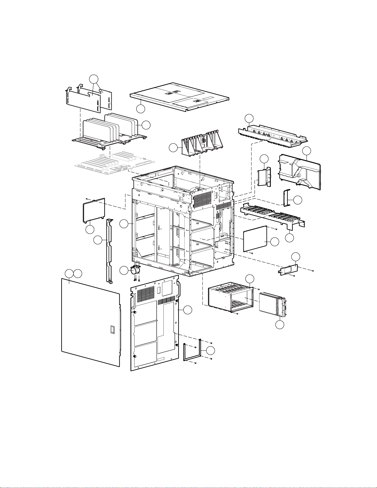
Mechanical Parts Exploded View
11e
3
2a
7
6g
14c
11f
12
4
5
1
11k
13
9
8a
10
14a
14b
2b
6a
Figure 1-1. Mechanical parts exploded view
8b
Page 12

Mechanical Spare Parts List
Item Description Spare Part Number
Chassis
1 Chassis 126978-001
2 Upper and lower processor guides 126972-001
a) Upper processor support structure
b) Lower processor support structure
3 Top access panel with access key 126979-001
4 Right side access panel 126991-001
5 Left side access panel 126991-001
6 Miscellaneous plastics kit 126983-001
a) Removable media blanking panel
Illustrated Parts Catalog 1-3
Table 1-1
Mechanical Spare Parts List
b) Flat ribbon cable clips*
c) Slide fillers*
d) LED holder clip*
e) Expansion board locking lever*
f) Cable grommet*
g) Expansion board guide
7 Hot-plug basket insulator 126980-001
Assemblies
8 Front bezel kit 126992-001
a) Front bezel, opal
b) Removable media trim, opal
9 Ultra2 drive cage with backplane board 126994-001
Miscellaneous
10 Hard drive blanking panel 122759-001
continued
Page 13

1-4 Compaq ProLiant 8000 Intel Pentium III Xeon 700MHz Servers Maintenance and Service Guide
Table 1-1
Mechanical Spare Parts List
Item Description Spare Part Number
11 Miscellaneous hardware kit 126984-001
a) Memory board retention bracket*
b) Expansion board blanking panel*
c) External SCSI slot blanking panel*
d) Redundant fan slot cover*
e) Extended SCSI dividers
f) Power supply blanking panel
g) Removable media blanking panel EMI shield*
h) Processor cage support brace*
i) Processor board support retainer*
j) Processor board support*
k) Hot-plug drive cage blanking panel
12 Power supply lock bar with lock kit 296201-001
continued
13 Casters 296227-001
14 Baffle kit 126993-001
a) Processor and VRM air baffle
b) Front air baffle
c) Rear air baffle
*Not shown
Page 14
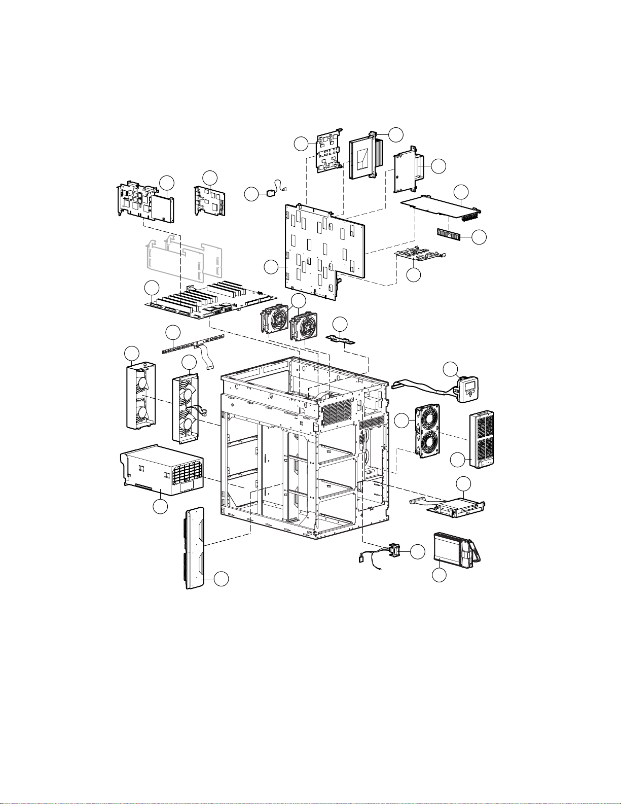
System Components Exploded View
Illustrated Parts Catalog 1-5
15
32
24
33
16
25
37
28
30
29
31
27
26
30
19
34
21
17
22
23
Figure 1-2. System components exploded view
18
35
20
36
Page 15

1-6 Compaq ProLiant 8000 Intel Pentium III Xeon 700MHz Servers Maintenance and Service Guide
System Components Spare Parts List
Table 1-2
System Components Spare Parts List
Item Description Spare Part Number
Assemblies
15 Hot-plug rear processor fans 126987-001
16 Redundant rear processor fans 126988-001
17 Redundant front processor fans 126990-001
18 Hot-plug front processor fans 126989-001
19 Hot-plug front I/O fan(s) 153312-001
20 Power On/Standby switch with cable and LED 126977-001
21 Integrated Management Display panel with cable 122223-001
System Components
22 Hot-plug power supply, 1150W 122235-001
Boards
23 Power backplane board, 12-blade 126975-001
24 Smart Array 4250ES controller 401858-001
25 NC3131 10/100 TX UTP Network Interface Controller (NIC) 338478-001
26 Memory module, 128-MB, 64-Mb CL2 (Quantity 1) 146488-001
27 Memory board 122215-001
28 Processor board with tray 126973-001
29 Processor, 700 MHz with 1-MB cache and heatpipe 178943-001
30 Processor Power Module (VRM) 312257-001
31 Processor terminator board 312334-001
32 I/O system board 126982-001
33 PCI Hot Plug switch board with cable 126981-001
34 Hot Plug I/O fan board assembly 312344-001
Mass Storage
35 24X Max IDE slimline CD-ROM/1.44-MB diskette drive assembly 126974-001
36 4.3-GB 1-inch 7,200 rpm Ultra2 hard drive with tray 242622-001
Miscellaneous
37 4.5V battery replacement 160274-001
continued
Page 16

Illustrated Parts Catalog 1-7
Table 1-2
System Components Spare Parts List
Item Description Spare Part Number
38 Miscellaneous screw kit* 154954-001
a) Screw, taptite, T-15, oval-head
b) Screw, 6-32x.312 inch, TF, HI/TP
c) Screw, shoulder, 6-32x.335 inch, Torx-15
d) Screw/washer
39 Miscellaneous power cable kit* 126986-001
a) 10-position, 6A, 6-inch power cable
b) 8-inch signal/power cable
c) Media bay 2 device power cable
d) External fan hot-plug power cable
e) Internal fan hot-plug power cable
f) 16-position, 9A, 17-inch power cable
g) 18-position, 9A, 19-inch power cable
continued
h) PCI Hot Plug, 50P, 8-inch power cable
I) 22-position, 9A, 18-inch power cable
40 Miscellaneous signal cable kit* 126985-001
a) 68-position A, B, C SCSI cable
b) 68-position, 46-inch, signal cable
c) CD-ROM/diskette drive, 30-inch, data power/signal cable
d) Wide SCSI signal cable with terminator
e) Internal bypass and thermistor, 8-inch cable
f) Fan hot-plug upstairs, 13-inch cable
41 Tower conversion kit* 126976-001
42 Rack mount kit* 161666-001
43 Country kit* 190418-001
44 Return kit* 306370-001
45 Carton and buns, international* 306370-002
46 Maintenance and service guide* 192848-001
continued
Page 17

1-8 Compaq ProLiant 8000 Intel Pentium III Xeon 700MHz Servers Maintenance and Service Guide
Table 1-2
System Components Spare Parts List
Item Description Spare Part Number
47 Illustrated parts map* 192847-001
Options
48 Keyboard* 160648-XXX
49 Ethernet loopback RJ-45* 317465-001
50 4.3-GB 1-inch 10,000 rpm Ultra2 hard drive with tray* 336380-001
51 9.1-GB 1-inch 7,200 rpm Ultra2 hard drive with tray* 104665-001
52 9.1-GB 1-inch 10,000 rpm Ultra2 hard drive with tray* 386536-001
53 18.2-GB 1-inch 7,200 rpm Ultra2 hard drive with tray* 104663-001
54 18.2-GB 1-inch 10,000 rpm Ultra2 hard drive with tray* 143920-001
55 9.1-GB 1-inch 10,000 rpm Ultra3 hard drive with tray 152188-001
56 18.2-GB 1-inch 10,000 rpm Ultra3 hard drive with tray 152190-001
57 Processor, 700 MHz with 2-MB cache and heatpipe* 178944-001
58 Cache Accelerator* 143887-001
continued
59 Memory module, 256-MB, 128-Mb, CL3 (Quantity 1)*
60 Memory module, 512-MB, 128-Mb, CL2 (Quantity 1)* 170515-001
61 Memory module, 256-MB, 64-Mb, CL2 (Quantity 1)* 170514-001
62 Memory module, 512-MB, 256-Mb, CL2 (Quantity 1)* 170515-001
63 Memory module, 512-MB, 128-Mb, CL3 (Quantity 1)* 170516-001
64 Memory module, 512-MB, 256-Mb, CL3 (Quantity 1)* 170517-001
65 Memory module, 1-GB, 256-Mb, CL2 (Quantity 1)* 170518-001
66 Memory module, 1-GB, 256-Mb, CL3 (Quantity 1)* 170519-001
*Not shown
146489-001
Page 18

Chapter 2
Removal and Replacement Procedures
This chapter provides subassembly/module-level removal and replacement procedures for
Compaq ProLiant 8000 servers. After completing all necessary removal and replacement
procedures, run the Diagnostics program to verify that all components operate properly.
To service Compaq ProLiant 8000 servers, you might need the following:
■ Flatblade screwdriver
■ Phillips screwdriver
■ Torx T-15 screwdriver
■ From the Compaq SmartStart and Support Software CD:
System Configuration Utility software
Drive Array Advanced Diagnostics software
Diagnostics software
Electrostatic Discharge Information
A discharge of static electricity can damage static-sensitive devices or microcircuitry. Proper
packaging and grounding techniques are necessary precautions to prevent damage. To prevent
electrostatic damage, observe the following precautions:
■ Transport products in static-safe containers such as conductive tubes, bags, or boxes.
■ Keep electrostatic-sensitive parts in their containers until they arrive at static-free stations.
■ Cover workstations with approved static-dissipating material. Provide a wrist strap
connected to the work surface and properly grounded tools and equipment.
■ Keep the work area free of nonconductive materials, such as plastic assembly aids and
foam packing.
■ Make sure you are always properly grounded when touching a static-sensitive component
or assembly.
■ Avoid touching pins, leads, or circuitry.
■ Always place drives PCB assembly-side down.
■ Use conductive field service tools.
Page 19
2-2 Compaq ProLiant 8000 Intel Pentium III Xeon 700MHz Servers Maintenance and Service Guide
Symbols in Equipment
WARNING: Any surface or area of the equipment marked with these symbols
indicates the presence of a hot surface or hot component.
If this surface is contacted, the potential for injury exists. To reduce the risk of
injury from a hot component, allow the surface to cool before touching it.
WARNING: Any surface or area of the equipment marked with these symbols
indicates the presence of electric shock hazards. The enclosed area contains no
operator-serviceable parts. To reduce the risk of injury from electric shock, do
not open this enclosure.
WARNING: Any product or assembly marked with these symbols indicates that the
weight in kg
weight in lb
component exceeds the recommended weight for one individual to handle safely.
To reduce the risk of personal injury or damage to the equipment, observe local
occupational health and safety requirements and guidelines for manual
material handling.
WARNING: Any RJ-45 receptacle marked with these symbols indicates a
Network Interface Connection. To reduce the risk of electric shock, fire, or
damage to the equipment, do not plug telephone or telecommunications
connectors into this receptacle.
CLASS 1 LASER PRODUCT
WARNING: This label or equivalent is located on the surface of your CD-ROM
drive. This label indicates that the product is classified as a CLASS 1 LASER
PRODUCT.
WARNING: To reduce the risk of injury from electric shock, remove all power
cords to completely disconnect power from the system. Power supplies marked
with these symbols indicate the equipment is supplied by multiple sources of
power.
Page 20
System Interlocks
Compaq ProLiant 8000 servers ship with system interlocks. System interlocks consist of three
LEDs providing a closed-loop checking mechanism for verifying proper cabling interconnects
between critical server components. These LEDs are located on both the I/O and the processor
boards. They provide a visual aid to assist in isolating components to check if the server will not
power up because of a broken interlock chain. The I/O board is located directly beneath the
PCI Hot Plug access doors under the top access panel. An amber system power LED on the
front of the server will illuminate whenever the interlock chain is broken.
Preparation Procedures
Hot-Pluggable Parts
Before beginning the removal of any serviceable parts, determine whether the part is
hot-pluggable or non-hot-pluggable. If it is hot-pluggable, do not perform a power shutdown of
the server. The access panels can be removed while the server is powered up without causing a
system shutdown. When the server is in Standby mode, portions of the power supply, auxiliary
power (+5V), and some internal circuitry will remain active.
Removal and Replacement Procedures 2-3
Non-Hot-Pluggable Parts
If any serviceable parts are non-hot-pluggable, then the server must be shut down.
Non-hot-pluggable parts include the processor, Processor Power Module, system board,
memory board, and DIMMs. Refer to “Turning Off the Server” later in this chapter for complete
instructions.
WARNING: To reduce the risk of injury from electric shock, remove all power
cords to completely disconnect power from the system. Power supplies
marked with these symbols indicate the equipment is supplied by multiple
sources of power.
Page 21
2-4 Compaq ProLiant 8000 Intel Pentium III Xeon 700MHz Servers Maintenance and Service Guide
Turning Off the Server
The ProLiant 8000 server’s Power On/Standby switch does not shut off the system power
completely. The switch functions as On and Standby, rather than On and Off. Standby mode
removes power from most of the electronics and the drives, but portions of the power supply
and some internal circuitry remain active.
IMPORTANT: To completely remove all power from the system, you must disconnect the power cord
from the server. In systems with multiple power supplies, you must disconnect all power cords to
completely remove power from the system.
IMPORTANT: It is not necessary to turn off the server to replace hot-plug devices, such as PCI Hot Plug
power supplies or hot-plug fans.
NOTE: It is necessary to be knowledgeable of electrostatic discharge information before performing the
preparation procedures. For electrostatic discharge information, see “Electrostatic Discharge
Information” earlier in this chapter.
Before beginning any removal and replacement procedure for non-hot-plug devices:
1. Press the Power On/Standby switch to Standby mode. This disables the main power
supply output and provides auxiliary power (+5V) to the server. Standby does not disable
main AC power.
2. Verify that the system LED on the front panel, near the Power On/Standby switch, is off
and that the fan noise abates.
3. Disconnect all power cords from the server.
4. For some removal and replacement procedures, you must remove the server from the rack
and place it on a sturdy table or workbench. Refer to the Compaq ProLiant 8000 Setup
and Installation Guide for instructions.
WARNING: To reduce the risk of personal injury or damage to the equipment:
46 – 109 kg
100 – 240 lb
WARNING: Because the rack allows you to stack computer components on a vertical rather
than horizontal plane, you must take precautions to provide for rack stability and safety. These
precautions also protect both personnel and property. Follow all cautions and warnings
throughout the installation instructions that came with the server.
■ Observe local Occupational Safety requirements and guidelines for heavy
equipment handling.
■ Obtain adequate assistance to lift and stabilize the product during installation or
removal.
■ Remove all pluggable power supplies and modules to reduce the weight of the
product.
■ Stabilize the server by keeping the unit on the rails.
Page 22
Rack Warnings
Removal and Replacement Procedures 2-5
WARNING: To reduce the risk of electric shock or damage to the equipment:
■ If the system has multiple power supplies, disconnect power from the system by
unplugging all power cords from the power supplies.
■ Do not disable the power cord grounding plug. The grounding plug is an important
safety feature.
■ Plug the power cord into a grounded (earthed) electric outlet that is easily accessible at
all times.
WARNING: To reduce the risk of personal injury or damage to the equipment, be sure that:
■ The leveling jacks are extended to the floor.
■ The full weight of the rack rests on the leveling jacks.
■ The stabilizers are attached to the rack if it is a single-rack installation.
■ The racks are coupled together in multiple-rack installations.
■ The rack is adequately stabilized before extending a component outside the rack.
■ One component is extended at a time.
WARNING: To reduce the risk of electric shock or damage to the equipment:
■ Do not disable the power cord grounding plug. The grounding plug is an important safety
feature.
■ Plug the power cord into a grounded (earthed) electric outlet that is easily accessible at all
times.
■ Install the power supply before connecting the power cord to the power supply.
■ Unplug the power cord before removing the power supply from the server.
■ If the system has multiple power supplies, disconnect power from the system by
unplugging all power cords from the power supplies.
CAUTION: Compaq ProLiant 8000 servers must always be operated with the system unit cover
on. Proper cooling will not be achieved if the system unit cover is removed.
Servers Warnings and Precautions
WARNING: To reduce the risk of personal injury from hot surfaces, allow the internal
system components to cool before touching them.
CAUTION: Protect the server from power fluctuations and temporary interruptions with a
regulating uninterruptible power supply (UPS). This device protects the hardware from damage
caused by power surges and voltage spikes and keeps the system in operation during a
power failure.
Page 23
2-6 Compaq ProLiant 8000 Intel Pentium III Xeon 700MHz Servers Maintenance and Service Guide
Top Access Panel
WARNING: To reduce the risk of personal injury from hot surfaces, allow the internal
system components to cool before touching them.
CAUTION: When the server is powered up, the access panel must be installed for proper
system cooling. Otherwise, component stress and permanent damage may result.
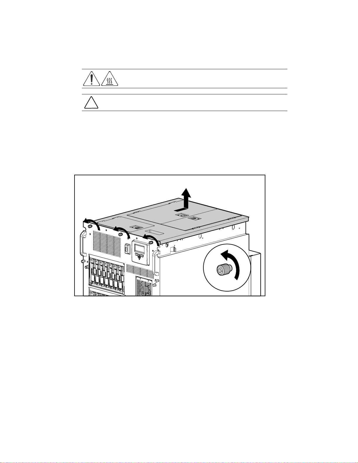
To remove the top access panel:
1. Perform the preparation procedures. See “Preparation Procedures” earlier in this chapter.
2. Loosen the three top thumbscrews located on the front of the chassis. The center screw has
no knurling and requires a T-15 screwdriver.
3. Using the top access panel handle, slide the top access panel back. Then lift it from
the chassis.
Figure 2-1. Removing the top access panel
Reverse steps 1 through 3 to replace the top access panel.
Page 24
Right Side Access Panel
WARNING: To reduce the risk of personal injury from hot surfaces, allow the internal
system components to cool before touching them.
CAUTION: When the server is powered on, the access panels must be installed for proper
system cooling. Otherwise, component stress and permanent damage may result.
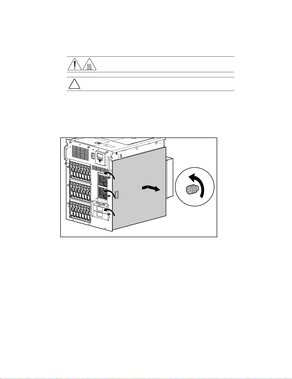
To remove the right side access panel:
1. Perform the preparation procedures. See “Preparation Procedures” earlier in this chapter.
2. Loosen the three side access panel screws on the front of the server. The center screw has
no knurling and requires a T-15 screwdriver.
3. Slide the right side access panel back, then pull it away from the chassis.
Removal and Replacement Procedures 2-7
Figure 2-2. Removing the right side access panel
Reverse steps 1 through 3 to replace the right side access panel.
Page 25
2-8 Compaq ProLiant 8000 Intel Pentium III Xeon 700MHz Servers Maintenance and Service Guide
Left Side Access Panel
WARNING: To reduce the risk of personal injury from hot surfaces, allow the internal
system components to cool before touching them.
CAUTION: When the server is powered on, the access panels must be installed for proper
system cooling. Otherwise, component stress and permanent damage may result.
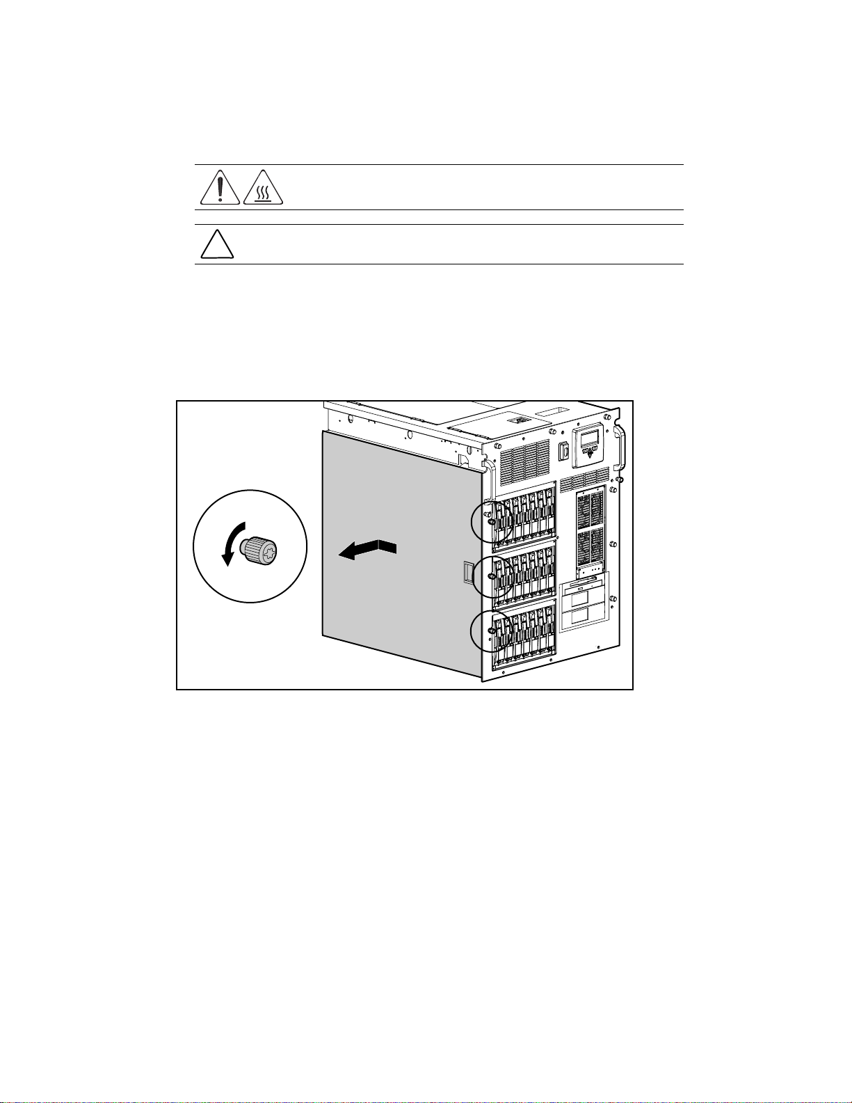
To remove the left side access panel:
1. Perform the preparation procedures. See “Preparation Procedures” earlier in this chapter.
2. Loosen the three side access panel screws on the front of the server. The center screw has
no knurling and requires a T-15 screwdriver.
3. Slide the left side access panel back, then pull it away from the chassis.
Figure 2-3. Removing the left side access panel
Reverse steps 1 through 3 to replace the left side access panel.
Page 26
Casters
Removal and Replacement Procedures 2-9
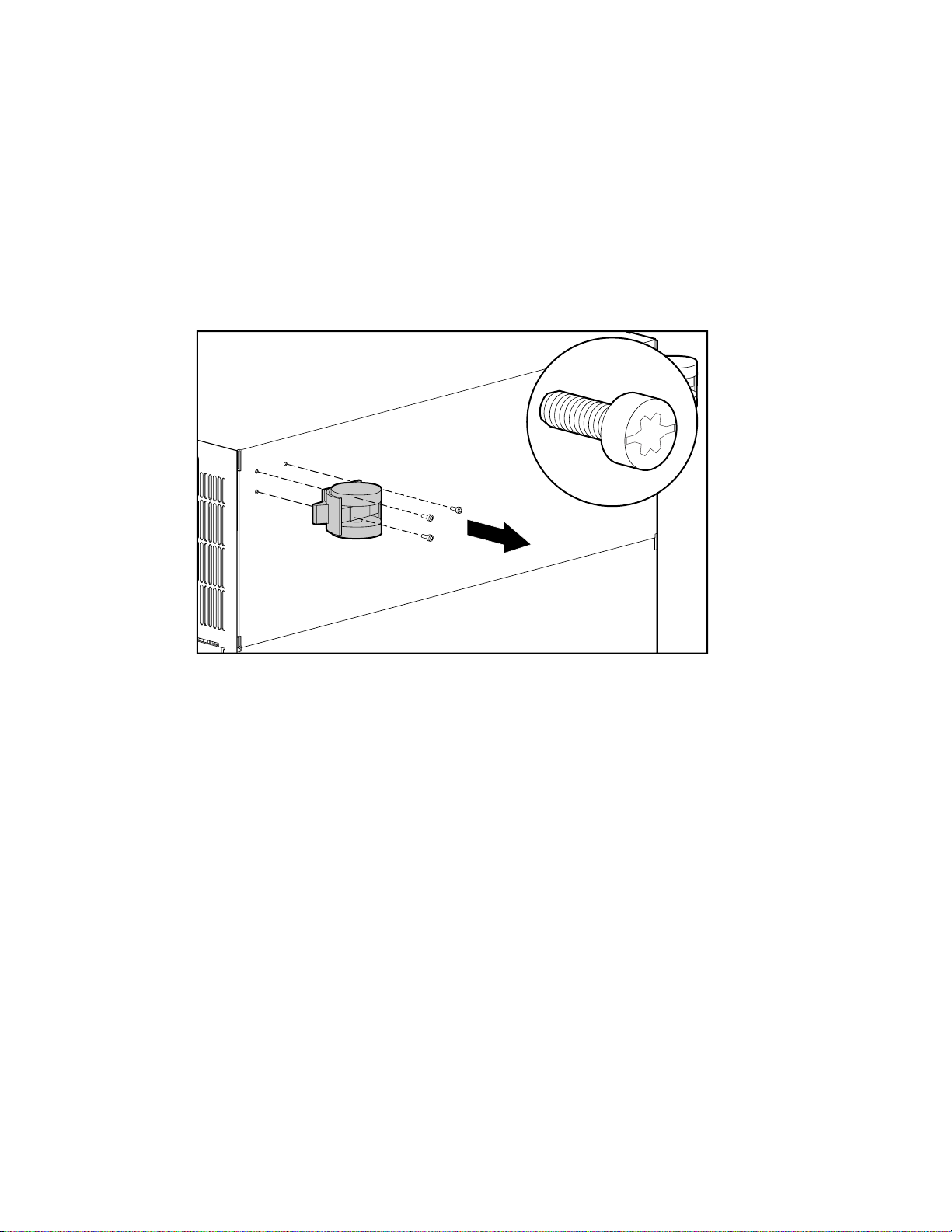
To remove the casters:
1. Perform the preparation procedures. See “Preparation Procedures” earlier in this chapter.
2. Place the server on its side.
3. Remove the three T-15 screws securing each caster to the bottom of the server.
4. Pull the casters away from the server.
Figure 2-4. Removing the casters
Reverse steps 1 through 4 to replace the casters.
Page 27

2-10 Compaq ProLiant 8000 Intel Pentium III Xeon 700MHz Servers Maintenance and Service Guide
Front Air Baffle
To remove the front air baffle:
1. Perform the preparation procedures. See “Preparation Procedures” earlier in this chapter.
2. Remove the right side access panel. See “Right Side Access Panel” earlier in this chapter.
3. Press in on the locking tabs at each end of the front air baffle
4. Pull the front air baffle out of the front fan assembly area
1
2
1
Figure 2-5. Removing the front air baffle
Reverse steps 1 through 4 to replace the front air baffle.
.
.
Page 28
Rear Air Baffle
To remove the rear air baffle:
1. Perform the preparation procedures. See “Preparation Procedures” earlier in this chapter.
2. Remove the right side access panel. See “Right Side Access Panel” earlier in this chapter.
Removal and Replacement Procedures 2-11
3. Press the release tab
server
Figure 2-6. Removing the rear air baffle
Reverse steps 1 through 3 to replace the rear air baffle.
(next to the rear fan assembly).
, then pivot and remove the rear air baffle from the rear of the
2
1
Page 29
2-12 Compaq ProLiant 8000 Intel Pentium III Xeon 700MHz Servers Maintenance and Service Guide
Main Processor Air Baffle
To remove the main processor air baffle:
1. Perform the preparation procedures. See “Preparation Procedures” earlier in this chapter.
2. Remove the right side access panel. See “Right Side Access Panel” earlier in this chapter.
3. Insert your thumb and index finger into the finger-grips
air baffle out
4. Lift the main processor air baffle out from the side of the server.
Figure 2-7. Removing the main processor air baffle
Reverse steps 1 through 4 to replace the main processor air baffle.
and away from the chassis.
2
1
, then pivot the main processor
Page 30
Face Plates
NOTE: The front bezel and the removable media trim can be removed independently of each other.
Removable Media Trim
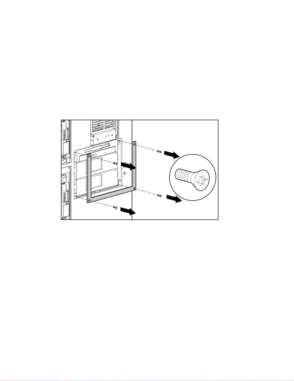
To remove the removable media trim:
1. Remove the four T-15 screws securing the removable media trim to the front of the
chassis.
2. Pull the frame away from the chassis.
Removal and Replacement Procedures 2-13
Figure 2-8. Removing the removable media trim
Reverse steps 1 and 2 to replace the removable media trim.
Page 31

2-14 Compaq ProLiant 8000 Intel Pentium III Xeon 700MHz Servers Maintenance and Service Guide
Front Bezel
To remove the front bezel:
1. Remove the twelve T-15 screws securing the front bezel to the chassis.
2. Pull the front bezel away from the server.
Figure 2-9. Removing the front bezel
Reverse steps 1 and 2 to replace the front bezel.
Page 32

Mass Storage and Removable Media Devices
Mass storage in Compaq ProLiant 8000 servers is divided between three hot-plug hard drive cages and
a removable media area. Mass storage and removable media devices include the following:
■ Up to seven 1-inch form factor Ultra2 hard drives (SCSI IDs 0 to 5, and 8) per drive cage
■ One slim-line combination CD-ROM/1.44-MB diskette drive
■ Two additional media bays
Figure 2-10 and Table 2-1 show the standard shipping configuration of the removable media
area and possible configurations for the hot-plug and Ultra2 SCSI drive cages in Compaq
ProLiant 8000 servers.
CAUTION: Removable media blank bezels and hot-plug drive cage blanking panels must be
installed over unused mass storage and removable media device bays to maintain proper air
flow.
Removal and Replacement Procedures 2-15
Cage #3
Cage #2
0 1 2 3 4 5 8
0 1 2 3 4 5 8
2
1
Cage #1
Figure 2-10. Mass storage and removable media areas
0 1 2 3 4 5 8
0
Table 2-1
Mass Storage and Removable Media Area Configurations
Drive Positions
Location
Hot-plug drive cage #3 0-5 and 8 Example of 1-inch hot-plug hard drives
Hot-plug drive cage #2 0-5 and 8 Example of 1-inch hot-plug hard drives
Hot-plug drive cage #1 0-5 and 8 Example of 1-inch hot-plug hard drives
Removable media bay 2 Non-hot-plug, integrated, 1.44 MB, 3.5-inch diskette
(SCSI Identification) Configuration
drive
Removable media bay 2 Non-hot-plug 24X Max IDE slimline CD-ROM drive
Removable media bay 0-1 Non-hot-plug mass storage devices
Page 33

2-16 Compaq ProLiant 8000 Intel Pentium III Xeon 700MHz Servers Maintenance and Service Guide
Removable Media Blanking Panel
To remove a removable media blanking panel from the removable media area:
1. Remove the removable media trim. See “Removable Media Trim” earlier in this chapter.
2. Remove the two T-15 screws securing the blank bezel to the chassis
3. Pull the blanking panel away from the front of the server
2
1
Figure 2-11. Removing a removable media blanking panel
.
1
Reverse steps 1 through 3 to replace the removable media blanking panel.
.
Page 34

Removable Media Devices
To remove a removable media device from the removable media area:
1. Perform the preparation procedures. See “Preparation Procedures” earlier in this chapter.
2. Remove the right side access panel. See “Right Side Access Panel” earlier in this chapter.
3. Disconnect the power and signal cables from the removable media device.
4. Remove the removable media trim. See “Removable Media Trim” earlier in this chapter.
Removal and Replacement Procedures 2-17
5. Remove the two retaining screws securing the removable media device to the chassis
6. Pull the removable media device from the removable media bay
1
Figure 2-12. Removing a removable media device
.
1
2
Reverse steps 1 through 6 to replace a removable media device in the removable media area.
.
Page 35

2-18 Compaq ProLiant 8000 Intel Pentium III Xeon 700MHz Servers Maintenance and Service Guide
Hard Drive Blanking Panels
To remove a hard drive blanking panel from a hard drive bay:
1. Press the lower release button
.
2. Pull the hard drive blanking panel away from the server
2
1
Figure 2-13. Removing a hard drive blanking panel from a hard drive bay
Reverse steps 1 and 2 to replace a hard drive blanking panel.
.
Page 36

Hot-Plug Drive Replacement Guidelines
You should be able to hot-plug a drive during normal activity. Be aware, however, that
hot-plugging a disk drive will affect system performance and fault tolerance.
NOTE: Depending upon your configuration, a drive failure and the subsequent rebuild process will cause
storage subsystem performance degradation. For example, the replacement of a single drive on an array
with 50 logical drives will have less impact than if the array has three logical drives.
When a disk drive is hot-plugged, although the system is functionally operational, the disk
subsystem may no longer be fault tolerant.
CAUTION: Fault tolerance will be lost until the removed drive is replaced and the rebuild
operation is completed (this will take several hours, even if the system is not busy while the
rebuild is in progress). If another drive in the array incurs an error during the period when fault
tolerance is unavailable, a fatal system error could result.. If another drive fails during this
period, the entire contents of the array will be lost.
IMPORTANT: Perform a disk drive replacement during low activity periods whenever possible. In
addition, have a current valid backup available for the logical drives in the array of the drive being
replaced, even if drive replacement is being made during server downtime.
Removal and Replacement Procedures 2-19
Hot-Plug Drive Replacement Precautions
Be aware of the following Compaq guidelines for safe hot-plug replacement:
■ Do not remove a degraded drive if any other member of the array is offline (the online
LED is off). No other drive in the array can be hot-plugged without data loss, unless
RAID 0+1 is used as a fault tolerant form. In this case, drives are mirrored in pairs. More
than one drive can fail and be replaced as long as the drive or drives they are mirroring are
online.
Refer to your Smart Array Controller user guide for information on fault tolerance
options.
■ Do not remove a degraded drive if any member of an array is missing (previously
removed and not yet replaced).
■ Do not remove a degraded drive if any member of an array is being rebuilt, unless the
drive being rebuilt has been configured as an online spare. The online LED for the drive
being rebuilt will flash, indicating that a replaced drive is being rebuilt from data stored on
the other drives.
NOTE: An online spare will not activate and start rebuilding after a predictive failure alert because the
degraded drive is still online. The online spare activates only after a drive in the array has failed.
■ Do not replace multiple degraded drives at the same time (for example, when the system is
off), or the fault tolerance may be compromised. When a drive is replaced, the controller
uses data from the other drives in the array to reconstruct data on the replacement drive. If
more than one drive is removed, a complete data set is not available to reconstruct data on
the replacement drive or drives, and permanent data loss could occur.
Page 37

2-20 Compaq ProLiant 8000 Intel Pentium III Xeon 700MHz Servers Maintenance and Service Guide
CAUTION: Do not turn off an attached disk drive enclosure when the server containing the
Smart Array Controller is powered on. Also, do not turn on the server before turning on the disk
enclosure. If these ordering rules are not followed, the Smart Array Controller may mark the
drives in this enclosure as “failed,” which could result in permanent data loss.
NOTE: For more information on hard drive LED statuses, refer to Chapter 4.
To remove a hot-plug SCSI hard drive:
CAUTION: Replace a hot-plug SCSI hard drive only when the drive LED is amber. Do not
remove a hot-plug SCSI hard drive if the online LED is green.
1. Press the release button for the SCSI hard drive ejector lever
2. Pull the locking release lever
3. Pull the hard drive from the drive cage
1
2
Figure 2-14. Removing a hot-plug SCSI hard drive
forward.
3
.
.
Reverse steps 1 through 3 to replace a hot-plug SCSI hard drive.
Page 38

Drive Cage with Backplane Board
To remove a drive cage with backplane board:
1. Perform the preparation procedures. See “Preparation Procedures” earlier in this chapter.
2. Remove the left side access panel. See “Left Side Access Panel” earlier in this chapter.
3. Disconnect the power and SCSI cables from the backplane board.
4. Remove all drives from the drive cage. See “Hot-Plug Drive Replacement Guidelines”
earlier in this chapter.
CAUTION: Hard drives removed from the drive bays must be replaced into the same slots from
which they were removed to preserve data integrity.
5. Remove the two slotted T-15 screws from the front of the drive cage.
6. Pull out the drive cage assembly.
Removal and Replacement Procedures 2-21
Figure 2-15. Removing the drive cage with backplane board
Reverse steps 1 through 6 to replace the drive cage with backplane board.
CAUTION: If an internal drive cage bay does not contain a drive cage, you must install a
hot-plug drive cage blanking panel to ensure proper system cooling.
Page 39

2-22 Compaq ProLiant 8000 Intel Pentium III Xeon 700MHz Servers Maintenance and Service Guide
Power On/Standby Switch
To remove the Power On/Standby switch:
1. Perform the preparation procedures. See “Preparation Procedures” earlier in this chapter.
2. Remove the top access panel. See “Top Access Panel” earlier in this chapter.
3. Disconnect the Power On/Standby switch connector from the I/O board location shown in
Figure 2-16.
4. Remove the power LED from the plastic LED holder on the chassis.
Figure 2-16. Disconnecting the Power On/Standby switch connector from the I/O board
Page 40

Removal and Replacement Procedures 2-23
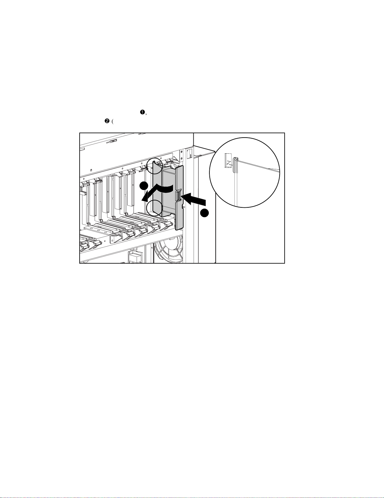
5. If the plastic switch cover is installed, remove it by prying outward on the upper or lower
catch
Figure 2-17. Removing the plastic switch cover
with a 4-mm flatblade screwdriver. Then pull the cover off the switch .
1
2
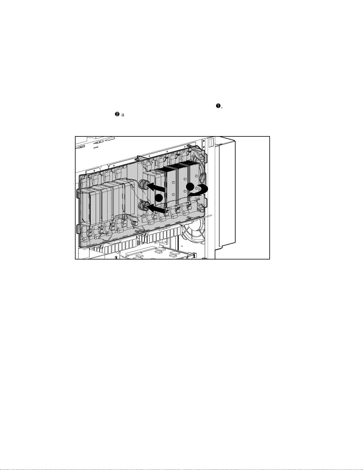
6. Press in on the release tabs
unit, push the assembly out of the front of the server
3
4
3
Figure 2-18. Removing the Power On/Standby switch and LED
on the Power On/Standby switch assembly. From behind the
.
Reverse steps 1 through 6 to replace the Power On/Standby switch and LED.
Page 41

2-24 Compaq ProLiant 8000 Intel Pentium III Xeon 700MHz Servers Maintenance and Service Guide
Power Supply Lock Bar
To remove the power supply lock bar:
1. Unlock the padlock securing the top end of the lock bar
2. Pull the top of the lock bar from its secured position
the server
Figure 2-19. Removing the power supply lock bar from its locking position
.
2
1
. Then lift the lock bar away from
.
3
Reverse steps 1 and 2 to replace the power supply lock bar.
Page 42

Power Supplies
Compaq ProLiant 8000 servers support up to three hot-plug power supplies. Compaq
ProLiant 8000 servers ship with two hot-plug, redundant, dual-rated, load sharing, 1150-Watt
power supplies in power supply bays 1 and 2. Depending on the system load configuration,
more than one power supply might be required to power the system. Table 2-2 shows the
minimal power supply loading requirements. To provide redundancy, add another power supply
to the ones shown in Table 2-2.
Figure 2-20 shows the position of the power supplies in the rear of the server.
Removal and Replacement Procedures 2-25
Power Supply #3
Power Supply #2
Power Supply #1
Figure 2-20. Power supply positioning (power supply #3 not shown)
CAUTION: To reduce the risk of data loss or damage to the equipment, any power supply bay
that is not populated with a power supply must be covered with a power supply blanking panel.
This ensures adequate airflow inside the server.
Table 2-2
Power Supply Requirements for System Load Configurations
Power
Supplies
Required
1 110 1 to 2 2 to 4 256 MB 1 to 3
1 220 1 to 4 15 to 21 256 MB to 4 GB 3 to 8
2 110 1 to 4 5 to 9 256 MB to 4 GB 3 to 6
2 220 1 to 8 15 to 21 256 MB to 16 GB 3 to 11
Note: Compaq recommends that 220 VAC power is used for all deployments. This will ensure that the server can
support its maximum configurations and remain in a redundant power supply state. This table does not imply that a
given power supply configuration can support the maximum number of processors, hard drives, memory, and PCI
expansion boards listed. Each power supply has a status and an AC power indicator. See Chapter 4, “Connectors,
Switches, and Status Indicators,” for descriptions and explanations of the power supply indicators.
Power Line
Voltage (VAC)
Number of
Processors
Number of
Hard Drives
Total Memory Number of
PCI/ISA Cards
Page 43

2-26 Compaq ProLiant 8000 Intel Pentium III Xeon 700MHz Servers Maintenance and Service Guide
Power Supply Blanking Panel
To remove a power supply blanking panel:
1. If installed, remove the power supply lock bar. See “Power Supply Lock Bar” earlier in
this chapter.
2. Remove the T-15 screw from the top of the blanking panel
.
3. Tilt the blanking panel outward 45 degrees. Then lift it away from the rear of the server
1
2
Figure 2-21. Removing a power supply blanking panel
Reverse steps 1 through 3 to replace a power supply blanking panel.
.
Page 44

Hot-Plug Power Supplies
To remove a hot-plug power supply:
1. In a redundant power supply configuration, it is unnecessary to turn off the power for a
hot-plug power supply replacement. For a non-redundant configuration, perform the
preparation procedures. See “Preparation Procedures” earlier in this chapter.
CAUTION: At least one power supply must be in place when changing out a hot-plug power
supply. If all three power supplies are to be changed out, perform a server shutdown.
2. Disconnect the power cord from the power supply. Use wire cutters to snip the
tie-wrap
, if one is present.
Removal and Replacement Procedures 2-27
1
Figure 2-22. Disconnecting the power cord
3. If installed, remove the power supply lock bar. See “Power Supply Lock Bar” earlier in
this chapter.
Page 45

2-28 Compaq ProLiant 8000 Intel Pentium III Xeon 700MHz Servers Maintenance and Service Guide
4. Press the center release lever of the power supply handle
downward to detach the power supply from the power backplane board
, then pull the handle
.
5. Using the handle, slide the power supply out the rear of the server while carefully
supporting the weight of the power supply
3
Figure 2-23. Removing a hot-plug power supply
.
2
1
Reverse steps 1 through 5 to replace a hot-plug power supply.
CAUTION: To reduce the risk of data loss or damage to the equipment, any power supply bay
that is not populated with a power supply must be covered with a blanking panel. This ensures
adequate airflow inside the server.
Page 46

Power Backplane Board
To remove the power backplane board:
1. Perform the preparation procedures. See “Preparation Procedures” earlier in this chapter.
2. Remove the left side access panel. See “Left Side Access Panel” earlier in this chapter.
3. Pull out the power supplies from the rear of the server far enough to disengage them from
the power backplane board
4. Unplug all cables from the power backplane board.
Removal and Replacement Procedures 2-29
. See “Hot-Plug Power Supplies” earlier in this chapter.
5. Loosen the two thumbscrews on the power backplane board
.
6. Rotate the power backplane board forward, then lift it out the left side of the server
2
2
3
Figure 2-24. Removing the power backplane board
1
1
Reverse steps 1 through 6 to replace the power backplane board.
.
IMPORTANT: Ensure that the ribbon cable is installed before turning on the server. When installing the
power backplane board, make sure the board is engaged in the upper and lower metal guides.
Page 47

2-30 Compaq ProLiant 8000 Intel Pentium III Xeon 700MHz Servers Maintenance and Service Guide
Fans
ProLiant 8000 servers ship with 10 cooling fans. There are four fan assemblies at the processor
area, two at the front and two at the rear of the server. An I/O fan assembly is located at the top
of the server. All fans become active at startup. After reaching proper operating conditions, the
redundant front and the redundant rear processor fans shut off. This is the normal fan sequence
for all ProLiant 8000 servers.
Hot-Plug Rear Processor Fan
To remove the hot-plug rear processor fan:
1. Loosen the captive retaining screw at the top of the external processor fan
2. Tilt the rear processor fan back
1
Figure 2-25. Removing the hot-plug rear processor fan
Reverse steps 1 and 2 to replace the hot-plug rear processor fan.
then pull it away from the chassis .
2
3
.
Page 48

Redundant Rear Processor Fan
To remove the redundant rear processor fan:
1. Perform the preparation procedures. See “Preparation Procedures” earlier in this chapter.
2. Remove the hot-plug rear processor fan to gain access to the redundant rear processor fan
retaining screws. See “Hot-Plug Rear Processor Fan” earlier in this chapter.
Removal and Replacement Procedures 2-31
3. Loosen the four T-15 screws
one quarter turn using a Torx screwdriver. Then remove
the screws by hand.
4. Disconnect the two fan cables from the processor board
5. Pull the redundant rear processor fan out the rear of the unit
2
Figure 2-26. Removing the redundant rear processor fan
.
.
1
3
1
Reverse steps 1 through 5 to replace redundant rear processor fan.
Page 49

2-32 Compaq ProLiant 8000 Intel Pentium III Xeon 700MHz Servers Maintenance and Service Guide
Hot-Plug Front Processor Fan Assembly
To remove the hot-plug front processor fan assembly:
1. Pull the lower fan ejector lever out
2. Rotate the fan assembly up
Figure 2-27. Removing the hot-plug front processor fan assembly
to release the hot-plug front processor fan assembly.
. Then lift the assembly away from the front of the server.
2
1
Reverse steps 1 and 2 to replace the hot-plug front processor fan assembly.
Page 50

Redundant Front Processor Fan Assembly
To remove the redundant front processor fan assembly:
1. Perform the preparation procedures. See “Preparation Procedures” earlier in this chapter.
2. Remove the hot-plug front processor fan assembly. See “Hot-Plug Front Processor Fan
Assembly” earlier in this chapter.
Removal and Replacement Procedures 2-33
3. Remove the two T-15 screws from the top of the redundant front processor fan assembly
4. Pull the upper part of the assembly forward
and unhook the bottom tab from the
lower slot.
5. Unplug the fan power cable
6. Lift out the fan assembly
1
at the terminal connector.
and fan power cable.
4
2
3
.
Figure 2-28. Removing the redundant front processor fan assembly
Reverse steps 1 through 6 to replace the redundant front processor fan assembly.
Page 51

2-34 Compaq ProLiant 8000 Intel Pentium III Xeon 700MHz Servers Maintenance and Service Guide
Hot-Plug Front I/O Fans
The two hot-plug front I/O fans are housed together in a cage assembly, but they can be
removed individually.
CAUTION: Never remove both hot-plug I/O fans while the server is powered up. Overheating
and damage to hardware could result. If appropriate Compaq software drivers are installed, the
operating system software will initiate a power shutdown if overheating occurs.
To remove a hot-plug front I/O fan:
1. Use the access key to unlock and open the hot-plug I/O fan access door in the top access
panel
. See “I/O Expansion Slots and Related Components” later in this chapter.
2. Hook one finger through the thumbstrap
the thumbstrap.
3. Lift the hot-plug I/O fan out of the fan cage
3
1
Figure 2-29. Removing a hot-plug front I/O fan
and push the locking latch toward
.
2
4
Page 52

To replace a hot-plug front I/O fan:
Removal and Replacement Procedures 2-35
1. Hook one finger through the thumbstrap and push the locking latch
toward
the thumbstrap.
2. Securely seat the hot-plug front I/O fan into the I/O fan cage
NOTE: An audible click should occur when the fan is fully seated.
.
3. Close and lock the hot-plug front I/O fan access door in the top access cover
2
1
3
.
Figure 2-30. Replacing a hot-plug front I/O fan
NOTE: When a hot-plug front I/O fan is properly installed, the fan produces air flow and the fan LED light
is green.
Page 53

2-36 Compaq ProLiant 8000 Intel Pentium III Xeon 700MHz Servers Maintenance and Service Guide
Hot-Plug I/O Fan Board
To remove the hot-plug I/O fan board:
1. Remove the top access panel. See “Top Access Panel” earlier in this chapter.
2. Remove the hot-plug front I/O fans. See “Hot-Plug Front I/O Fans” earlier in this chapter.
3. Remove the two Torx T-8 screws securing the hot-plug I/O fan board to the fan cage
4. Slide the board from beneath the hot-plug I/O fan cage, then lift it out of the server
1
2
Figure 2-31. Removing the hot-plug I/O fan board
Reverse steps 1 through 4 to replace the hot-plug I/O fan board.
.
.
Page 54

SDRAM Memory
Compaq ProLiant 8000 servers use industry-standard synchronous dynamic RAM (SDRAM)
dual inline memory modules (DIMMs) with single-bit error correction and single/multiple-bit
error detection down to a single DIMM. Memory is expandable to 16 GB (16 x 1-GB DIMMs)
by using all 16 DIMM sockets, two DIMM sockets to a bank. Both DIMMs in a bank must be
the same size, type, and speed, and both DIMMs in a bank must be installed at the same time.
Compaq ProLiant 8000 servers support 128-MB, 256-MB, 512-MB, and 1-GB 100-MHz
SDRAM DIMMs.
IMPORTANT: The Power-On Self-Test (POST) warns of non-supported DIMMs. Mixing of memory speeds
on a memory expansion board is allowed, but the memory expansion board will run at the slowest
memory speed installed.
Dual Inline Memory Modules
Table 2-3 gives examples of DIMM upgrade combinations for Compaq ProLiant 8000 servers.
Examples of DIMM Upgrade Combinations
Removal and Replacement Procedures 2-37
Table 2-3
Total
Memory Bank 1 Bank 2 Bank 3 Bank 4 Bank 5 Bank 6 Bank 7 Bank 8
512 MB 2 x 128 MB 2 x 128 MB
1 GB 2 x 128 MB 2 x 128 MB 2 x 128 MB 2 x 128 MB
1.5 GB 2 x 128 MB 2 x 128 MB 2 x 128 MB 2 x 128 MB 2 x 128 MB 2 x 128 MB
2 GB 2 x 256 MB 2 x 256 MB 2 x 256 MB 2 x 256 MB
4 GB 2 x 256 MB 2 x 256 MB 2 x 256 MB 2 x 256 MB 2 x 256 MB 2 x 256 MB 2 x 256 MB 2 x 256 MB
4.0 GB 2 x 512 MB 2 x 512 MB 2 x 512 MB 2 x 512 MB
6.1 GB 2 x 512 MB 2 x 512 MB 2 x 512 MB 2 x 512 MB 2 x 512 MB 2 x 512 MB
8 GB 2 x 512 MB 2 x 512 MB 2 x 512 MB 2 x 512 MB 2 x 512 MB 2 x 512 MB 2 x 512 MB 2 x 512 MB
16 GB 2 x 1 GB 2 x 1 GB 2 x 1 GB 2 x 1 GB 2 x 1 GB 2 x 1 GB 2 x 1 GB 2 x 1 GB
IMPORTANT: Compaq recommends using only Compaq DIMMs. DIMMs from other sources can
adversely affect data integrity. Refer to the Compaq ProLiant 8000 Setup and Installation Guide for
information on achieving optimum performance of the memory system.
Page 55

2-38 Compaq ProLiant 8000 Intel Pentium III Xeon 700MHz Servers Maintenance and Service Guide
Memory Expansion Board
Figure 2-32 shows the DIMM socket and memory bank locations on the memory expansion
board for ProLiant 8000 servers.
DIMM 2
DIMM 4
DIMM 6
DIMM 8
DIMM 10
DIMM 12
DIMM 14
BANK
1
2
3
4
5
6
7
8
DIMM 16
Figure 2-32. DIMM socket and memory bank locations on the memory expansion board
CAUTION: Compaq recommends using only Compaq DIMMs. DIMMs from other sources
might adversely affect data integrity.
IMPORTANT: Memory must be installed in identical pairs. Ensure all modules in a logical bank of two
have the same 9-digit Compaq part number. Populate bank 1 (slots 1 and 2) first. Continue populating
the memory banks in sequential order. Populate bank 8 last. If the memory is not matched as stated,
then the server will experience POST Error 207.
DIMM 1
DIMM 3
DIMM 5
DIMM 7
DIMM 9
DIMM 11
DIMM 13
DIMM 15
Page 56

Removal and Replacement Procedures 2-39
To remove the memory expansion board:
1. Perform the preparation procedures. See “Preparation Procedures” earlier in this chapter.
2. Remove the right side access panel. See “Right Side Access Panel” earlier in this chapter.
3. Remove the memory expansion board retention bracket by loosening the thumbscrew
swinging the left side of the bracket out of the slot
left and out the side of the unit
2
Figure 2-33. Removing the memory expansion board retention bracket
.
3
, and then pulling the bracket to the
1
,
Page 57

2-40 Compaq ProLiant 8000 Intel Pentium III Xeon 700MHz Servers Maintenance and Service Guide
4. Rotate the ejector levers outward
slide the board out of the server
Figure 2-34. Removing the memory expansion board
on each side of the memory expansion board. Then
.
5
4
Reverse steps 1 through 4 to replace the memory expansion board.
4
IMPORTANT: When installing a memory expansion board, verify that the board aligns with the
connectors on the processor board. If the memory expansion board is not properly seated, the system
interlock circuitry prevents the system from powering up.
IMPORTANT: Secure the thumbscrews in order for the unit to operate properly. See the warning label on
the processor board cage for the service screw locations.
NOTE: Remember to remove any memory modules from the replaced memory expansion board and
insert them into the proper sockets on the new memory expansion board.
Page 58

Removal and Replacement Procedures 2-41
To remove a DIMM:
1. Perform the preparation procedures. See “Preparation Procedures” earlier in this chapter.
2. Remove the memory expansion board containing the DIMM modules. See “Memory
Expansion Board” earlier in this chapter.
3. Support the underside of the memory expansion board.
CAUTION: The ejectors prevent the memory expansion board from lying completely flat.
Inserting a DIMM without proper support behind the socket on the expansion board can cause
the board to flex and could result in damage to the board.
4. Push down on the release levers at each end of the selected DIMM
5. Lift the DIMM from the memory expansion board
1
Figure 2-35. Removing a DIMM
.
2
.
1
Reverse steps 1 through 5 to replace a DIMM. Align the key slot on the bottom edge of each
DIMM with the tab in the DIMM socket before seating the DIMM in the socket. If the
alignment notches do not line up, it is not the correct memory specification.
IMPORTANT: Be certain the release levers are completely closed.
Page 59

2-42 Compaq ProLiant 8000 Intel Pentium III Xeon 700MHz Servers Maintenance and Service Guide
Cache Accelerators
Cache accelerators are found where more than one processor bus is used. Figure 2-36 shows the
location of cache accelerators
and .
1
2
Figure 2-36. Cache accelerators
CAUTION: Cache accelerators are susceptible to damage from electrostatic discharge. Do not
touch the metal chassis while removing the accelerators.
IMPORTANT: For best performance, install the first four processors in processor slots 1-4. Cache
accelerators must be used if processors are installed on both buses.
Operating the server with processors installed in both buses but without the cache accelerators will
prevent the system from booting and will cause an error message to be displayed.
Page 60

Removal and Replacement Procedures 2-43
To remove a cache accelerator:
1. Perform the preparation procedures. See “Preparation Procedures” earlier in this chapter.
2. Remove the right side access panel. See “Right Side Access Panel” earlier in this chapter.
3. Remove the main processor air baffle. See “Main Processor Air Baffle” earlier in
this chapter.
4. Remove the processor support brace by loosening the two thumbscrews
brace away from the server
Figure 2-37. Removing the processor support brace
.
2
1
. Then pull the
Page 61

2-44 Compaq ProLiant 8000 Intel Pentium III Xeon 700MHz Servers Maintenance and Service Guide
5. Open the lower ejector tab securing the cache accelerator
6. Remove the accelerator from the socket
Figure 2-38. Removing a cache accelerator
.
Reverse steps 1 through 6 to replace a cache accelerator.
.
4
3
After replacing the cache accelerator, complete the following steps to clear the cache accelerator
POST Error 220.
1. Reboot the server and press F9 to enter the ROM-based System Configuration Utility.
2. When in the utility, select Advanced Options.
3. Select Set Cache Accelerator Corrected.
4. Select the slot that has been corrected (1 or 2).
5. Press ESC twice and then F10 to save.
At this point the bit in NVRAM is cleared. If the cache accelerator replacement has been
successful, then POST Error 220 will no longer display at reboot.
Page 62

Removal and Replacement Procedures 2-45
Processors, Processor Power Modules, Processor Terminator Boards, Processor Board with Tray
The processor board with tray seats up to eight processors and eight Processor Power Modules.
CAUTION: Terminator boards must be installed in each unoccupied processor slot to complete
the system interlock feature.
Figure 2-39 and Table 2-4 show processor, Processor Power Module, and terminator slot
numbers and locations.
6 7 8 9 10 11 12
5
4
3
2
1
Figure 2-39. Processor, Processor Power Module, and terminator board slot locations
Table 2-4
Processor Board Slot Locations
Item Description Item Description
Processor slot 8
Processor Power Module 8
Processor slot 7
Processor Power Module 7
Processor slot 6
Processor Power Module 6
Processor slot 5
Processor Power Module 5
Processor slot 4
Processor Power Module 4
Processor slot 3
Processor Power Module 3
Processor slot 2
Processor Power Module 2
Processor slot 1
Processor Power Module 1
13
14
15
16
Page 63

2-46 Compaq ProLiant 8000 Intel Pentium III Xeon 700MHz Servers Maintenance and Service Guide
Processor
Each processor bus in ProLiant 8000 servers supports four processors. Figure 2-40 illustrates
how the processors are properly removed using the ejectors.
o
90
Figure 2-40. Unlocking and ejecting the processor
90
o
120
o
120
o
To remove a processor:
1. Perform the preparation procedures. See “Preparation Procedures” earlier in this chapter.
2. Remove the right side access panel. See “Right Side Access Panel” earlier in this chapter.
3. Remove the main processor air baffle. See “Main Processor Air Baffle” earlier in
this chapter.
4. Unlock the processor by opening the side ejector levers outward 90 degrees.
NOTE: Processor side ejectors unlock at 90 degrees and eject the processor from the processor slot at
120 degrees.
Page 64

Removal and Replacement Procedures 2-47
5. Eject the processor from the processor slot by opening the ejector levers 120 degrees
6. Remove the processor from the processor slot
Figure 2-41. Removing a processor
.
1
2
1
When installing new processors, follow these guidelines:
■ Use Intel Pentium III Xeon processors. ProLiant 8000 servers do not support Pentium II
Xeon processors.
.
■ ProLiant 8000 servers will not boot if Intel Pentium III Xeon 500/550-MHz processors
and Pentium III Xeon 700-MHz or higher speed processors are installed in the same
server.
■ When installing processors, be sure to install the Processor Power Module first.
■ Processors must be installed starting from the slot closest to the rear of the server (slot 1).
■ Each pair of processor slots must contain processors of the same cache size (processor slot
pairs are Slots 1 and 2; Slots 3 and 4; Slots 5 and 6; and Slots 7 and 8). If there is no match
for a processor, the second slot in the pair must be filled with a processor terminator
board.
■ The processor pair with the lowest cache size should be installed in the lowest numbered
processor slot. If a second pair of processors has a larger cache size, it should be installed
in the next pair of slots.
■ The cache size of processors on a bus must not differ by more than two cache size options.
■ All slots must have either a processor or terminator board installed.
Page 65

2-48 Compaq ProLiant 8000 Intel Pentium III Xeon 700MHz Servers Maintenance and Service Guide
Table 2-5 shows examples of processors installed using these guidelines.
Table 2-5
Examples of Processor Mixing by Cache Size
Example Processors 1 and 2 Processors 3 and 4 Processors 5 and 6 Processors 7 and 8
1
2
1 MB 1 MB 1 MB 2 MB
1 MB 1 MB Terminator Board 2 MB
1 MB 2 MB 2 MB Terminator Board
1 MB 2 MB Terminator Board Terminator Board
With the bus/core ratio switches in the default position, the system ROM automatically detects
the speed of processors installed on both processor buses. The processors automatically run at
the speed of the slowest processor installed in the server.
The default setting for the bus/core ratio switches has all switches in the Off position. Compaq
recommends that the bus/core ratio switches remain on the default setting to allow the system
ROM to detect the correct speed automatically. If necessary, the bus/core ratio switches can be
manually set to force processor speed settings. See “Processor Board Bus/Core Frequency Ratio
Switch Settings” in Chapter 4 for manual bus/core frequency switch settings.
CAUTION: If the bus/core ratio switches are set to a speed higher than the slowest processor,
the server will not boot. Failure to properly set the bus/core ratio switches could damage the
server and void the warranty.
Page 66

Removal and Replacement Procedures 2-49
To install a processor:
CAUTION: When installing processors, be sure to install the Processor Power Module first to
ensure proper processor operation.
1. Gently guide the processor into the processor slot.
IMPORTANT: If the processor is not properly seated, the system interlock prevents the system from
powering up.
2. Fully seat the processor
NOTE: The processor is keyed to ensure correct alignment.
CAUTION: Do not lock the ejector levers before fully seating the processor into the slot.
IMPORTANT: When installing a processor, push down on both levers simultaneously. The server may
not recognize the processor if it is not properly installed.
3. Push both side ejector levers on the processor inward
.
to lock the processor in place.
2
1
2
Figure 2-42. Installing a processor
4. Replace the main air baffle and access covers.
5. Restart the server.
IMPORTANT: Verify that the processor board bus/core switch settings are correct. See Chapter 4,
“Connectors, Switches, and Status Indicators,” for the correct bus/core switch settings.
Page 67

2-50 Compaq ProLiant 8000 Intel Pentium III Xeon 700MHz Servers Maintenance and Service Guide
Processor Power Modules
The Processor Power Modules (which are also called VRMs) of Compaq ProLiant 8000 servers
have built-in redundancy to prevent the system from powering down if a Processor Power
Module fails. There is one redundant Processor Power Module per server. The redundant
Processor board Processor Power Module (ninth VRM), located below the eight processor slots,
ships with every server model.
To remove the redundant processor board Processor Power Module:
1. Perform the preparation procedures. See “Preparation Procedures” earlier in this chapter.
2. Remove the right side access panel. See “Right Side Access Panel” earlier in this chapter.
3. Loosen the thumbscrew securing the Processor Power Module support bracket. Then pull
out the bracket
.
4. Rotate the side ejector levers on the module outward
right side of the server
Figure 2-43. Removing the processor board Processor Power Module
.
3
. Then slide the module out the
2
1
Reverse steps 1 through 4 to replace the processor board Processor Power Module.
Page 68

Removal and Replacement Procedures 2-51
To remove a Processor Power Module:
1. Perform the preparation procedures. See “Preparation Procedures” earlier in this chapter.
2. Remove the right side access panel. See “Right Side Access Panel” earlier in this chapter.
3. Remove the main processor air baffle. See “Main Processor Air Baffle” earlier in
this chapter.
4. Remove the processor associated with the Processor Power Module being replaced. Refer
to Figure 2-39 and the “
Page 69

2-52 Compaq ProLiant 8000 Intel Pentium III Xeon 700MHz Servers Maintenance and Service Guide
Processors, Processor Power Modules, Processor Terminator Boards, Processor Board
with Tray” section earlier in this chapter.
5. Rotate the side ejector levers on the module outward
right side of the server
Figure 2-44. Removing a Processor Power Module
.
. Then slide the module out the
1
2
1
Page 70

Removal and Replacement Procedures 2-53
To install a Processor Power Module:
CAUTION: The redundant Processor Power Module must be installed before the processor.
Attempting to install the Processor Power Module after installing the processor could damage
the electronic components on the Processor Power Module.
1. Line up the Processor Power Module with the guides in the processor cage at the
appropriate processor board slot
.
2. Open the Processor Power Module ejector levers to 90 degree angles. Then fully seat the
Processor Power Module into its processor board slot.
CAUTION: Do not push the Processor Power Module into place by pushing on the
ejector levers.
3. Push the Processor Power Module onto the processor board until the levers lower to a flat
position
NOTE: An audible click should occur, indicating that the Processor Power Module is fully seated.
.
Figure 2-45. Replacing a Processor Power Module
NOTE: The Processor Power Module is keyed for correct alignment.
2
1
2
Page 71

2-54 Compaq ProLiant 8000 Intel Pentium III Xeon 700MHz Servers Maintenance and Service Guide
Processor Terminator Boards
Processor terminator boards occupy unused processor sockets on the processor board.
To remove a processor terminator board:
1. Perform the preparation procedures. See “Preparation Procedures” earlier in this chapter.
2. Remove the right side access panel. See “Right Side Access Panel” earlier in this chapter.
3. Remove the main processor air baffle. See “Main Processor Air Baffle” earlier in
this chapter.
4. Rotate the side ejector levers on the processor terminator board outward approximately
120 degrees
, then slide the processor terminator board out the right side of the server .
1
2
1
Figure 2-46. Removing a processor terminator board
Reverse steps 1 through 4 to replace a processor terminator board.
IMPORTANT: If the processor terminator board is not properly seated, the system interlock prevents the
system from powering up.
Page 72

Lower Processor Support Structure
To remove the lower processor support structure:
1. Perform the preparation procedures. See “Preparation Procedures” earlier in this chapter.
2. Remove the right side access panel. See “Right Side Access Panel” earlier in this chapter.
3. Remove the front and rear air baffles. See “Front Air Baffle” and “Rear Air Baffle” earlier
in this chapter.
4. Remove the main processor air baffle. See “Main Processor Air Baffle” earlier in
this chapter.
5. Remove all processors, Processor Power Modules, and terminator boards. See “
Removal and Replacement Procedures 2-55
Page 73

2-56 Compaq ProLiant 8000 Intel Pentium III Xeon 700MHz Servers Maintenance and Service Guide
Processors, Processor Power Modules, Processor Terminator Boards, Processor Board
with Tray” earlier in this chapter.
6. Remove the processor support brace. See “Cache Accelerators” earlier in this chapter.
7. Loosen the two thumbscrews at each end of the lower processor support structure
8. Move the lower processor support structure forward slightly. Then pull it out from the
right side of the chassis
Figure 2-47. Removing the lower processor support structure
.
1
2
Reverse steps 1 through 8 to replace the lower processor support structure.
.
Page 74

Upper Processor Support Structure
To remove the upper processor support structure:
1. Perform the preparation procedures. See “Preparation Procedures” earlier in this chapter.
2. Remove the lower processor support structure. See “Lower Processor Support Structure”
earlier in this chapter.
3. Remove the five T-15 screws located along the top of the upper processor support
structure.
4. Pull out the upper processor support structure.
Removal and Replacement Procedures 2-57
Figure 2-48. Removing the upper processor support structure
Reverse steps 1 through 4 to replace the upper processor support structure.
Page 75

2-58 Compaq ProLiant 8000 Intel Pentium III Xeon 700MHz Servers Maintenance and Service Guide
Processor Board with Tray
To remove the processor board with tray:
1. Perform the preparation procedures. See “Preparation Procedures” earlier in this chapter.
2. Remove the top access panel. See “Top Access Panel” earlier in this chapter.
3. Remove the right side access panel. See “Right Side Access Panel” earlier in this chapter.
4. Remove the memory expansion board. See “Memory Expansion Board” earlier in
this chapter.
5. Remove the main processor air baffle. See “Main Processor Air Baffle” earlier in
this chapter.
6. Remove all Processor Power Modules except the Processor board Processor Power
Module (ninth VRM), processors, and terminator boards. See “
Page 76

Removal and Replacement Procedures 2-59
Processors, Processor Power Modules, Processor Terminator Boards, Processor Board
with Tray” earlier in this chapter.
7. Remove the front and rear air baffles. See “Front Air Baffle” and “Rear Air Baffle” earlier
in this chapter.
8. Loosen the two processor support brace thumbscrews
support brace
Figure 2-49. Removing the processor support brace
.
2
. Then lift out the processor
1
9. Remove the lower processor support structure. See “Lower Processor Support Structure”
earlier in this chapter.
10. Remove the Processor board Processor Power Module (ninth VRM). See “Processor
Power Modules” earlier in this chapter.
Page 77

2-60 Compaq ProLiant 8000 Intel Pentium III Xeon 700MHz Servers Maintenance and Service Guide
11. Loosen the two thumbscrews
support structure. Then remove the support structure
Figure 2-50. Removing the Processor board Processor Power Module support structure
securing the Processor board Processor Power Module
from the processor board.
4
3
12. Disconnect all internal cables from the processor board.
13. Disconnect the exterior serial port keyboard, mouse, and printer cables from the rear of the
I/O board.
14. Loosen the two thumbscrews securing the I/O board to the processor board
5
5
Figure 2-51. Loosening the two thumbscrews joining the I/O (system) and processor boards
.
Page 78

Removal and Replacement Procedures 2-61
15. Loosen the two thumbscrews securing the processor board with tray to the chassis
16. Press the lock lever button with a finger or thumb
handle
.
17. Lower the processor board with tray from the back of the chassis
the board from the chassis
9
10
.
and pull down the processor board
. Then tilt and unhook
6
6
7
8
2
.
Figure 2-52. Removing the processor board with tray
Reverse steps 1 through 17 to replace the processor board with tray.
IMPORTANT: If the processor board is not properly seated, the system interlock prevents the system
from powering up. Secure the service thumbscrews so the unit will operate properly. See the warning
label on the processor board cage for the service screw locations.
NOTE: Ensure that all cables are out of the way when reseating the processor board and tray.
Page 79

2-62 Compaq ProLiant 8000 Intel Pentium III Xeon 700MHz Servers Maintenance and Service Guide
Integrated Management Display
To remove the Integrated Management Display (IMD):
1. Perform the preparation procedures. See “Preparation Procedures” earlier in this chapter.
2. Remove the top access panel. See “Top Access Panel” earlier in this chapter.
3. Disconnect the IMD cable from the I/O board.
4. Press in on the four locking tabs on the rear of the IMD
5. Pull the IMD from the front of the server
1
1
1
2
1
Figure 2-53. Removing the IMD
.
Reverse steps 1 through 5 to replace the IMD.
.
Page 80

I/O Expansion Slots and Related Components
The I/O expansion slots are located on the I/O board directly beneath the top access panel and
are accessed using the PCI Hot Plug access doors.
To access the I/O expansion slots:
Removal and Replacement Procedures 2-63
1. Insert the access key into the PCI Hot Plug access door and turn it counter-clockwise
NOTE: Compaq recommends leaving the PCI Hot Plug access doors locked during normal use.
1
Figure 2-54. Unlocking the PCI Hot Plug access doors
WARNING: To reduce the risk of personal injury from hot surfaces, allow the internal system
components to cool before touching them.
.
Page 81

2-64 Compaq ProLiant 8000 Intel Pentium III Xeon 700MHz Servers Maintenance and Service Guide
2. Slide back the locking lever on the PCI Hot Plug access door
3. Open the PCI Hot Plug access doors
3
Figure 2-55. Opening the PCI Hot Plug access doors
.
.
2
Page 82

Removal and Replacement Procedures 2-65
Figure 2-56 shows the Compaq ProLiant 8000 I/O expansion board slot positions from the top
of the server and; Figure 2-57 shows the slot positions from the back of the server. Table 2-6
shows which devices the slots can support.
NOTE: The I/O expansion board slots are numbered from right to left as you face the front of the server.
3
2
1
Figure 2-56. Top view of the I/O expansion board slots
Table 2-6
I/O Expansion Board Slots
Item Description
32-bit PCI Hot Plug (slot 1)
64-bit PCI Hot Plug (slots 2 through 9)
64-bit PCI Hot Plug with Extended SCSI (slots 10 and 11)
Page 83

2-66 Compaq ProLiant 8000 Intel Pentium III Xeon 700MHz Servers Maintenance and Service Guide
1 2 3
Figure 2-57. Rear view of the I/O expansion board slots
4
5 6 7 8 9 10 11
Table 2-7
I/O Expansion Board Slots
Item Description
, ,
, , ,
32-bit/33-MHz PCI Hot Plug (universal or 5-V keying)
32-bit or 64-bit/33-MHz PCI Hot Plug (universal or 5-V keying)
32-bit or 64-bit/33-MHz PCI Hot Plug, NC 3131 Fast Ethernet Dual 10/100 NIC
32-bit or 64-bit/33-MHz PCI Hot Plug (universal or 5-V keying)
Note: Hot-plug I/O expansion board slots (11 total) can be accessed through the PCI Hot Plug access doors.
64-bit/66-MHz hot-plug with Extended SCSI, Smart Array 4250ES Controller or other
Extended SCSI controller
64-bit/66-MHz hot-plug with Extended SCSI
Page 84

Array Controllers with Extended SCSI
To remove an array controller with Extended SCSI architecture:
1. Unlock then open the PCI Hot Plug access doors. See “I/O Expansion Slots” earlier in
this chapter.
2. Deactivate the expansion board slot LED by pressing the square button on the
PCI switchboard
CAUTION: Do not open the slot release lever unless the green PCI Hot Plug LED indicator for
the slot is off. System power down and subsequent data loss could occur. Never remove an
active controller unless it is in a redundant configuration.
.
Removal and Replacement Procedures 2-67
3. When the green LED is off, push down on the slot release lever
free the array controller.
4. Slide the slot keeper
4
Figure 2-58. Releasing an array controller with Extended SCSI
to the open position.
1
then push it back to
2
3
Page 85

2-68 Compaq ProLiant 8000 Intel Pentium III Xeon 700MHz Servers Maintenance and Service Guide
5. Pull the ejector levers outward
Figure 2-59. Removing an array controller with Extended SCSI
. Then lift the board from the unit .
5
5
6
Page 86

To replace an array controller with Extended SCSI:
Removal and Replacement Procedures 2-69
1. Line up the controller with the appropriate slot
.
2. Push the controller into the bus slot.
NOTE: Seat the controller into the slot using the ejector levers to ensure complete board connection.
3. Press the ejector levers inward to lock the long side of the control board into position
4. Push the slot release lever inward to lock the rear section of the controller into position
NOTE: An audible click should occur, indicating that the controller is fully seated.
2
3
1
.
.
Figure 2-60. Replacing an array controller with Extended SCSI
Page 87

2-70 Compaq ProLiant 8000 Intel Pentium III Xeon 700MHz Servers Maintenance and Service Guide
Extended SCSI Dividers
Extended SCSI dividers, adjacent to slots 10 and 11, provide leverage for removing and
replacing extended SCSI array controllers and add insulation to any PCI board plugged into
these slots.
To remove an Extended SCSI divider:
1. Perform the preparation procedures. See “Preparation Procedures” earlier in this chapter.
2. Remove the top access panel. See “Top Access Panel” earlier in this chapter.
3. Remove the array controllers with Extended SCSI. See “Array Controllers with Extended
SCSI” earlier in this chapter.
4. Pull up the single push-pull fastener
.
5. Push in the locking lever on the expansion board guide
divider out of the unit
2
Figure 2-61. Removing an Extended SCSI divider
.
3
and lift the Extended SCSI
1
Reverse steps 1 through 5 to replace an Extended SCSI divider.
Page 88

I/O Expansion Boards
This removal and replacement section is for standard I/O expansion boards that are available as
options. The board pictured in Figure 2-62 is an Extended SCSI type I/O expansion board.
To remove an I/O expansion board:
1. Unlock and open the PCI Hot Plug access door. See “I/O Expansion Slots” earlier in this
chapter.
2. Use the PCI Hot Plug button or software application to turn off power to the slot. The green LED
flashes during the power down transition and turns off when system shutdown is complete. For
more information refer, to the Compaq ProLiant 8000 Servers Setup and Installation Guide.
CAUTION: DO NOT open the slot release lever unless the green PCI Hot Plug LED power
indicator for the slot is off. If the lever is opened before power to the slot is turned off, system
power down and subsequent data loss could occur. For more information on the power LEDs,
refer to Chapter 4, “Connectors, Switches, and Status Indicators.”
3. When the green LED for the slot is off, disconnect the cables to the selected PCI
expansion board.
Removal and Replacement Procedures 2-71
4. Push the tab on the slot release lever
, then swing the slot release lever back to unlock
the expansion board.
5. Slide the slot keeper to the open position if the expansion board is full length
6. Disconnect any cables plugged into the selected expansion board.
7. Lift the expansion board through the top of the server
1
2
.
3
4
.
Figure 2-62. Removing an I/O expansion board
Reverse steps 1 through 7 to replace the I/O expansion board.
IMPORTANT: Installing a 33-MHz expansion board into a 66-MHz slot will cause the adjoining expansion
slot to run at 33-MHz even if it is populated by a 66-MHz expansion board. Both populated slots will run
at the slower 33-MHz rate.
Page 89

2-72 Compaq ProLiant 8000 Intel Pentium III Xeon 700MHz Servers Maintenance and Service Guide
Cabling Diagrams
Figure 2-63. Connecting the PCI SCSI controller board to removable media bays (typical)
Page 90

Removal and Replacement Procedures 2-73
Cage 3
Cage 2
Cage 1
Figure 2-64. Connecting an array controller with Extended SCSI to drive cage 1, 2, or 3
Page 91

2-74 Compaq ProLiant 8000 Intel Pentium III Xeon 700MHz Servers Maintenance and Service Guide
Hot-Plug Basket Insulator
To remove the hot-plug basket insulator:
1. Perform the preparation procedures. See “Preparation Procedures” earlier in this chapter.
2. Remove the top access panel. See “Top Access Panel” earlier in this chapter.
3. Remove the NC3131 Fast Ethernet NIC. See “I/O Expansion Boards” earlier in this
chapter.
4. Remove the array controller with Extended SCSI. See “Array Controllers with Extended
SCSI” earlier in this chapter.
5. Remove the Extended SCSI dividers. See “Extended SCSI Dividers” earlier in
this chapter.
6. Remove any installed I/O expansion boards. See “I/O Expansion Boards” earlier in
this chapter.
7. Disconnect cables for the power switch, the PCI Hot-Plug interface, and the fan and
speaker.
8. Pull up on the hot-plug basket insulator tab to release the basket
forward to release it from the keyholes.
9. Lift the hot-plug basket insulator out the top of the server
2
1
Figure 2-65. Removing the hot-plug basket insulator
Reverse steps 1 through 9 to replace the hot-plug basket insulator.
.
. Then move the basket
Page 92

Expansion Board Guide
To remove the expansion board guide:
1. Perform the preparation procedures. See “Preparation Procedures” earlier in this chapter.
2. Remove the top access panel. See “Top Access Panel” earlier in this chapter.
3. Remove any full-length expansion boards from the expansion board slots. See “I/O
Expansion Boards” earlier in this chapter.
4. Remove the cables for the fan, speaker, and power switch from the I/O board.
5. Slide the cables through the expansion board guide.
6. Disconnect the Power On/Standby switch cable from the I/O board.
7. Remove the Extended SCSI dividers. See “Extended SCSI Dividers” earlier in
this chapter.
Removal and Replacement Procedures 2-75
8. Press down on the two release grips on the board guide
9. Push the expansion board guide firmly toward the rear of the unit. Then lift the board
out
of the server.
2
Figure 2-66. Removing the expansion board guide
Reverse steps 1 through 9 to replace the expansion board guide.
.
1
Page 93

2-76 Compaq ProLiant 8000 Intel Pentium III Xeon 700MHz Servers Maintenance and Service Guide
PCI Hot Plug Interface Board
To remove the PCI Hot Plug interface board:
1. Remove the top access panel. See “Top Access Panel” earlier in this chapter.
2. Disconnect the cable securing the interface board to the system board
.
3. Remove the extended SCSI dividers. See “Extended SCSI Dividers” earlier in
this chapter.
4. Remove all I/O expansion boards. See “I/O Expansion Boards” earlier in this chapter.
5. Open the PCI expansion slot levers.
6. Pull the six push-pull fasteners to release the interface board
7. Pull the interface board away from the sheet metal
3
2
.
.
1
Figure 2-67. Removing the PCI Hot Plug interface board
Reverse steps 1 through 7 to replace the PCI Hot Plug interface board.
Page 94

I/O Board
Removal and Replacement Procedures 2-77
To remove the I/O board:
1. Perform the preparation procedures. See “Preparation Procedures” earlier in this chapter.
2. Remove the array controller with Extended SCSI. See “Array Controllers with Extended
SCSI” earlier in this chapter.
3. Remove any I/O expansion boards. See “I/O Expansion Boards” earlier in this chapter.
4. Remove the Extended SCSI Dividers. See “Extended SCSI Dividers” earlier in
this chapter.
5. Remove the hot-plug basket insulator. See “Hot-Plug Basket Insulator” earlier in
this chapter.
6. Disconnect all cables from the I/O board.
7. Loosen the I/O board captive thumbscrews
8. Lift up on the ejector lever to release the I/O board
to release them from the push-pull pins
3
2
Figure 2-68. Removing the I/O board
.
.
. Then gently pull up the board ends
1
Page 95

2-78 Compaq ProLiant 8000 Intel Pentium III Xeon 700MHz Servers Maintenance and Service Guide
9. Tilt the board from the back of server to clear the video connector
10. Lift the I/O board through the top of the server
Figure 2-69. Clearing the video connector area of the I/O board
.
4
5
Reverse steps 1 through 10 to replace the I/O board.
.
Page 96

External Battery
To install the external replacement battery:
1. Perform the preparation procedures. See “Preparation Procedures” earlier in this chapter.
2. Remove the right side access panel. See “Right Side Access Panel” earlier in this chapter.
Removal and Replacement Procedures 2-79
CAUTION: Do not remove the lithium battery from the processor board or permanent damage
may occur. If the battery fails, use the external battery as a replacement.
CAUTION: Batteries, battery packs, and accumulators should not be disposed of
together with the general household waste. In order to forward them to recycling or
proper disposal, use the public collection system or return them to Compaq, your
authorized Compaq Partners, or their agents.
3. Connect the battery cable to battery header E1 on the processor board
IMPORTANT: Compaq ProLiant 8000 servers provide two external battery headers for replacement
batteries. Header E1 provides connection for an external battery if the onboard battery fails. Header E2
provides connection for a second replacement battery, if necessary. Plug the second replacement battery
to header E2, attach the second replacement battery to the chassis, then unplug and remove the first
replacement battery.
.
4. Remove the adhesive backing from the hook-and-loop fastener strip.
5. Place the battery and the hook-and-loop fastener strip on the chassis
6. Change the switch setting on the processor board from INT BATT to EXT BATT
3
.
1
.
2
Figure 2-70. Installing the external replacement battery
Page 97

2-80 Compaq ProLiant 8000 Intel Pentium III Xeon 700MHz Servers Maintenance and Service Guide
7. Place the sticker included with your battery kit on the back of your server above the
power connector.
IMPORTANT: You must run the Compaq System Configuration Utility to reconfigure the server after
installing a replacement battery.
Page 98

Chapter 3
Diagnostics and Troubleshooting
This chapter describes software and firmware diagnostic tools available for all Compaq server
products. The sections in this chapter are:
■ Diagnostic Tools Utility Overview
■ Default Configuration
■ Utilities Access
■ Power-On Self-Test
■ Diagnostics Software
■ Array Diagnostic Utility
■ Integrated Management Log
■ Rapid Error Recovery
■ Remote Service Features
■ ROMPaq Error Recovery Options
■ Compaq Insight Manager
Page 99

3-2 Compaq ProLiant 8000 Intel Pentium III Xeon 700MHz Servers Maintenance and Service Guide
Diagnostic Tools Utility Overview
These utilities were developed to assist in diagnosing problems, testing the hardware, and
monitoring and managing Compaq server hardware.
Table 3-1
Diagnostic Tools
Tool What it is How to run it
Compaq Diagnostics
Program
Compaq Inspect
Utility
Compaq Insight
Manager
Compaq Survey
Utility
Utility to assist testing and/or verifying
operation of Compaq hardware. If
problems are found, Compaq
Diagnostics isolates failure(s) down to
replaceable part, whenever possible.
The Inspect Utility provides a report
detailing system information.
A client/server application used to
remotely manage Compaq hardware in
a network environment. Reports
hardware fault conditions (both failure
and pre-failure) and collects data for
reporting and graphing.
An online information gathering agent
that runs on servers, gathering critical
hardware and software information
from various sources. A utility for
servers running Windows NT or
NetWare.
If a significant change occurs between
data gathering intervals, previous
information is marked, and the survey
text file is overwritten to reflect the
latest configuration and changes since
last configuration. This allows a
historical record of change events for
server hardware and software.
Diagnostics and Utilities are located on
the system partition on the hard drive
and must be accessed when a system
configuration error is detected during
Power-On Self-Test (POST). Compaq
Diagnostics software is also available on
the Compaq SmartStart and Support
Software CD. A Diagnostics diskette can
be created from SmartStart and Support
Software CD.
The Inspect Utility can be run from either
the main menu of the System
Configuration Utility or the Compaq
Diagnostics program.
For more information, refer to the
Compaq Management CD and the
Compaq Insight Manager User Guide.
More information on viewing and printing
the event list can be found in the Compaq
Insight Manager section of this chapter.
Install Survey Utility from the SmartStart
and Support Software CD, Compaq
Integration Maintenance Utility, or from
Compaq Management CD.
continued
Page 100

Table 3-1
Diagnostic Tools
Tool What it is How to run it
continued
Diagnostics and Troubleshooting 3-3
Array Diagnostics
Utility (ADU)
Drive Array
Advanced
Diagnostics (DAAD)
Integrated
Management Log
A Windows-based tool designed to run
on all Compaq systems that support
Compaq array controllers. Two main
functions of ADU are to collect all
possible information about the array
controllers in the system and to
generate a list of detected problems.
This tool is available for all Compaq
servers covered by this guide.
The predecessor to ADU, DAAD is a
DOS-based tool for Compaq servers
with Smart Array Controllers. DAAD
collects information about the array
controllers in the system and offers a
list of detected problems.
A log of system events, such as system
failures or nonfatal error conditions.
View events in the Integrated
Management Log:
■ On the Integrated Management
Display
■ From within Compaq Insight
Manager
■ From within Compaq Survey Utility
Use the information provided in Array
Diagnostics Utility (ADU) later in this
chapter.
For a list of Compaq servers still
supported by this tool, visit the Compaq
website:
http://www.compaq.com
The Integrated Management Log requires
Compaq operating system-dependent
drivers. Refer to the Compaq Support
Software CD for instructions on installing
the appropriate drivers.
System
Configuration Utility
A utility to easily configure the hardware
installed in or connected to the server.
Specifically, it can:
■ Resolve resource conflicts in areas
such as memory, port addresses,
and interrupts (IRQs)
■ Configure PCI boards automatically
■ Provide switch and jumper settings
■ Manage installation of memory,
processor upgrades, and mass
storage devices such as hard
drives, tape drives, and diskette
drives
■ Store configuration information in
nonvolatile memory
■ Assist in installation of an operating
system
■ Assist in running diagnostic tools
such as TEST and INSPECT
If the server has bootable CD-ROM drive,
run Compaq System Configuration Utility
directly from Support Software CD
supplied with the Smart Controller Option
Kit, or SmartStart and Support
Software CD supplied with server. Use
the CD supplied for latest version
supporting SMART Controller.
If the server does not have a bootable
CD-ROM drive, create diskettes with
latest version of the System
Configuration Utility from Support
Software CD, or SmartStart and Support
Software CD.
 Loading...