

Page 1

ONLINE STORAGE
CONTROLLER RECOVERY
OPTION
USER GUIDE
Page 2

. . . . . . . . . . . . . . . . . . . . . . . . . . . . . .
Online Storage Controller
Recovery Option
User Guide
First Edition (September 1997)
Part Number
Compaq Computer Corporation
295586-001
Page 3

. . . . . . . . . . . . . . . . . . . . . . . . . . . . .
Notice
The information in this publication is subject to change without notice.
COMPAQ COMPUTER CORPORATION SHALL NOT BE LIABLE FOR TECHNICAL OR
EDITORIAL ERRORS OR OMISSIONS CONTAINED HEREIN, NOR FOR INCIDENTAL OR
CONSEQUENTIAL DAMAGES RESULTING FROM THE FURNISHING, PERFORMANCE, OR
USE OF THIS MATERIAL. THIS INFORMATION IS PROVIDED “AS IS” AND COMPAQ
COMPUTER CORPORATION DISCLAIMS ANY WARRANTIES, EXPRESS, IMPLIED OR
STATUTORY AND EXPRESSLY DISCLAIMS THE IMPLIED WARRANTIES OF
MERCHANTABILITY, FITNESS FOR PARTICULAR PURPOSE, GOOD TITLE AND AGAINST
INFRINGEMENT.
This publication contains information protected by copyright. No part of this publication may be
photocopied or reproduced in any form without prior written consent from Compaq Computer
Corporation.
1997 Compaq Computer Corporation.
All rights reserved. Printed in the U.S.A.
The software described in this guide is furnished under a license agreement or nondisclosure agreement.
The software may be used or copied only in accordance with the terms of the agreement.
This publication does not constitute an endorsement of the product or products that were tested. The
configuration or configurations tested or described may or may not be the only available solution. This
test is not a determination of product quality or correctness, nor does it ensure compliance with any
federal, state, or local requirements. Compaq does not warrant products other than its own strictly as
stated in Compaq product warranties.
Compaq, SMART-2, ProLiant, and NetFlex are registered with the United States Patent and Trademark
Office.
Netelligent and ProSignia are trademarks and/or service marks of Compaq Computer Corporation.
Microsoft, Windows, and Windows NT are registered trademarks of Microsoft Corporation.
Product names mentioned herein may be trademarks and/or registered trademarks of their respective
companies.
Online Storage Controller Recovery Option User Guide
First Edition (September 1997)
Part Number 295586-001
Page 4

. . . . . . . . . . . . . . . . . . . . . . . . . . . . . .
iii
Contents
How To Use This Guide
How this Guide is Arranged.......................................................................................... vii
Symbols In Text............................................................................................................ viii
Symbols in Equipment ....................................................................................................ix
Getting Help ....................................................................................................................xi
Telephone Numbers .................................................................................................xi
Compaq Web Site.................................................................................................. xiii
Chapter 1
Elements of the Online Storage Controller Recovery Option Solution
Hardware Requirements............................................................................................... 1-1
Software Requirements ................................................................................................ 1-2
Kit Contents..................................................................................................................1-3
Chapter 2
Functionality and Configuration Options
Redundancy at the Mass Storage Controller Level...................................................... 2-1
Merging two SMART-2 Controllers into a Controlled Pair ........................................ 2-2
Configuration Options.................................................................................................. 2-4
Single-Channel Configuration .............................................................................. 2-6
Dual-Channel Configuration................................................................................. 2-8
Multiple Controller Pairs....................................................................................... 2-9
Internal vs. External Boot Device....................................................................... 2-10
Online Storage Controller Recovery Option User Guide
Page 5

. . . . . . . . . . . . . . . . . . . . . . . . . . . . . .
iv
Chapter 3
Planning and Installing the Online Storage Controller Recovery Option
Hardware Planning....................................................................................................... 3-1
Controllers for OSCRO Implementation .............................................................. 3-1
Dual-Channel Configuration Considerations........................................................3-2
Knockout Panels.................................................................................................... 3-2
OSCRO Planning Implications..................................................................................... 3-3
Potential Impact on Unattended Reboot ............................................................... 3-4
Boot Device Configuration Planning.................................................................... 3-4
Array Acceleration Disabled.................................................................................3-5
Recovery Server Option Incompatibility.............................................................. 3-5
Setting Up for OSCRO Installation..............................................................................3-5
Installing the Recovery Server Switch in the ProLiant Storage System/F or /U.. 3-6
Upgrading the SMART-2 Array Controller Firmware .........................................3-9
Updating the SMART-2 Array Controller Device Drivers................................. 3-10
Loading the Compaq SSD for Windows NT ...................................................... 3-10
Installation.................................................................................................................. 3-13
Installing the Controllers.....................................................................................3-14
Labeling the Cables.............................................................................................3-15
Connecting the Cables......................................................................................... 3-16
Merging Two Controllers into a Controller Pair................................................. 3-20
Testing and Verifying the Installation........................................................................3-22
Chapter 4
Compaq Online Storage Controller Recovery Utility
Major Functions............................................................................................................ 4-1
Right-Click Functionality.............................................................................................4-2
Mass Storage Controller Icons .....................................................................................4-3
Viewing Device Properties...........................................................................................4-6
Setting Machine Options............................................................................................ 4-10
Page 6

. . . . . . . . . . . . . . . . . . . . . . . . . . . . . .
Chapter 5
Troubleshooting
Controllers Must Be Matched ...................................................................................... 5-1
Planning for OSCRO when RSO is in Use .................................................................. 5-1
Incorrect Cabling.......................................................................................................... 5-1
Cross Connection .................................................................................................. 5-2
Unilateral Connection ........................................................................................... 5-4
Mismatched Controller Pairs................................................................................. 5-6
Clearing a Cable Check Error....................................................................................... 5-7
Verify Does Not Switch Back...................................................................................... 5-7
Wrong Device Driver ...................................................................................................5-7
Controller Not Seen on the Online Storage Controller Recovery Utility ....................5-7
Boot Device Considerations......................................................................................... 5-8
Chapter 6
Recovering from Mass Storage Controller Failure
Recovering from Mass Storage Controller Failure Using PCI Hot Plug
Technology................................................................................................................... 6-1
Recovering from Mass Storage Controller Failure Without PCI Hot Plug
Technology................................................................................................................... 6-3
Boot Device Considerations......................................................................................... 6-3
v
Chapter 7
Dissolving a Controller Pair.........................................................................
Appendix A
Electrostatic Discharge
Preventing Electrostatic Damage ............................................................................... A-1
Grounding Methods....................................................................................................A-1
Online Storage Controller Recovery Option User Guide
7-1
Page 7

. . . . . . . . . . . . . . . . . . . . . . . . . . . . . .
vi
Appendix B
Regulatory Compliance Notices
Class A Equipment......................................................................................................B-1
Modifications........................................................................................................B-1
Cables................................................................................................................... B-1
Canadian Notice (Avis Canadien)...............................................................................B-1
Class A Equipment...............................................................................................B-1
European Union Notice................................................................................................B-2
Japanese Notice ...........................................................................................................B-3
Australian Notice.........................................................................................................B-3
Appendix C
Building Diskettes from the SmartStart and Support Software CD
Building Diskettes for the SMART-2 Array Controller Firmware Upgrade..............C-1
Building Diskettes for the Compaq System Configuration Utility
version 2.36 rev. A ......................................................................................................C-4
Index
Page 8

. . . . . . . . . . . . . . . . . . . . . . . . . . . . . .
vii
How To Use This Guide
This guide provides procedures for configuring, installing, maintaining, and
supporting the Online Storage Controller Recovery Option (OSCRO). It is
designed to be a reference for implementing and troubleshooting OSCRO
configurations. The other high-availability options in the Recovery Server
Option/F kit, Standby Recovery Server and On-Line Recovery Server, are covered
in the Recovery Server Option User Guide (part number 213818-004), which is
also in the kit.
How this Guide is Arranged
The manual is divided into the following chapters:
■ Chapter 1 - Elements of the Online Storage Controller Recovery
Option Solution
This section covers the hardware and software requirements of the
Online Storage Controller Recovery Option and provides a breakdown
of the contents of the kit.
■ Chapter 2 - Functionality and Configuration Options
This section describes the basic functionality and benefits of OSCRO
and details configuration options.
■ Chapter 3 - Planning and Installing the Online Storage Controller
Recovery Option
This section provides step-by-step instructions for planning and
installing OSCRO.
■ Chapter 4 - Compaq Online Storage Recovery Utility
This section describes the use of the Compaq Online Storage Controller
Recovery Utility.
■ Chapter 5 - Troubleshooting
This section describes error conditions and incorrect configurations of
OSCRO.
■ Chapter 6 - Recovery from Mass Storage Controller Failure
This section details recovery procedures to be used when a mass storage
controller fails under OSCRO.
■ Chapter 7 - Dissolving a Controller Pair
This section explains how and when to dissolve a controller pair.
Online Storage Controller Recovery Option User Guide
Page 9
. . . . . . . . . . . . . . . . . . . . . . . . . . . . . .
viii How To Use This Guide
■ Appendixes include important information related to electrostatic
discharge, regulatory compliance notices, and how to build diskettes
from the SmartStart and Support Software CD.
Symbols In Text
WARNING: Text set off in this manner indicates that failure to follow
directions in the warning can result in bodily harm or loss of life.
CAUTION: Text set off in this manner indicates that failure to follow
directions can result in damage to equipment or loss of information.
IMPORTANT: Text set off in this manner presents clarifying information or specific
instructions.
NOTE: Text set off in this manner presents commentary, sidelights, or interesting
points of information.
Page 10

. . . . . . . . . . . . . . . . . . . . . . . . . . . . . .
ix
Text Conventions
Convention Use
Keys
USER INPUT User input appears in a different typeface
Keys appear in boldface. A plus sign (+)
between two keys indicates that they
should be pressed simultaneously.
and in uppercase
FILENAMES
Menu Options, Command Names,
Dialog Box Names
COMMANDS, DIRECTORY NAMES,
and DRIVE NAMES
Type When you are instructed
Enter When you are instructed
Symbols in Equipment
WARNING: Any surface or area of the equipment marked with
these symbols indicates the presence of a hot surface or hot
component. If this surface is contacted, the potential for injury
exists. To reduce the risk of injury from a hot component, allow the
surface to cool before touching.
File names appear in uppercase italics
These appear in initial capital letters
These always appear in uppercase
to type
information, type the information
pressing the
information, type the information and
then press the
Enter
Enter
key
key
without
to enter
Online Storage Controller Recovery Option User Guide
Page 11
. . . . . . . . . . . . . . . . . . . . . . . . . . . . . .
x How To Use This Guide
WARNING: Any surface or area of the equipment marked with
these symbols indicates the presence of electrical shock hazards.
Enclosed area contains no operator-serviceable parts. To reduce
the risk of injury from electrical shock hazards, do not open this
enclosure.
WARNING: Any RJ-45 receptacle marked with these symbols
indicates a Network Interface Connection. To reduce the risk of
electrical shock, fire, or damage to the equipment, do not plug
telephones or telecommunications connectors into this receptacle.
WARNING: Some products are equipped with a three-wire, electrical
grounding-type plug that has a third pin for grounding. This plug only fits
into a grounded electrical outlet. This is a safety feature. Do not defeat the
safety purpose of the grounding-type plug by trying to insert it into a nongrounded outlet. If you cannot insert the plug into the outlet, contact your
electrician to replace the obsolete outlet.
Page 12

. . . . . . . . . . . . . . . . . . . . . . . . . . . . . .
A
A
A
A
xi
Getting Help
If you have a problem and have exhausted the information in this guide, you
can get further information and other help in the following locations.
Telephone Numbers
Contact your nearest Compaq Authorized Reseller or Service Provider for more
information.
■ For the name of your nearest Compaq Authorized Reseller:
❏ In the United States, call 1-800-345-1518
❏ In Canada, call 1-800-263-5868
■ For Compaq technical support:
❏ In the United States and Canada, call 1-800-386-2172
❏ Elsewhere, call one of the numbers listed below
Compaq Worldwide Technical Support Telephone Numbers
Location Voice FAX
PD 65-7503030 65-7504909
rgentina 54-1 313 3100 54-1 313 3100 Ext 21
ustralia 61-2-9911-1955 61-2-9911-1900
ustria 0222-87816-16 0222-87816-82
Bahrain 973-210-214
Belgium (02) 716-96-96 (02) 725-22-13
Brazil 55 11 5505-3600 55 11 5505-3922 Ext 4336
Canada 1-800-386-2172
Caribbean 1-800-345-1518
Central America 713-378-2206
Continued
Online Storage Controller Recovery Option User Guide
Page 13

. . . . . . . . . . . . . . . . . . . . . . . . . . . . . .
xii How To Use This Guide
Compaq Worldwide Technical Support Telephone Numbers
Location Voice FAX
Chile 562-274-3007
China 86-10-834-6721 86-10-834-6713
Colombia 571-345-0266 571-312-0157
Czech Republic 42-2-232-8772 42-2-232-8773
Denmark 45-90-4545 45-90-4595
Ecuador 593-2504540
Europe/Middle East/Africa (49) 089-9933-2891
Finland 9800-206-720
(358-800-1-206720)
France (33 1) 41-33-4455 (33 1) 41-33-4263
Germany 0180-5-212111 089-9933-3399
Hong Kong 852-90116633 852-28671734
Hungary 36-1-201-8776 36-1-201-9696
India (91-80) 559-6023
Italy 392-57-90300 392-575-00686
Japan 0120-101589 81 3-5402-5959
Korea 82-2-523-3575 82-2-3471-0321
Malaysia (603) 718-1636
Mexico (525) 229-7910 (525) 229-7988
Netherlands 06-91681616 06-8991116
New Zealand 649-307-3969
Norway 22-072-020 22-072-021
Poland 48-2-630-3535 48-2-630-3553
Portugal 351-1-4120132 351-1-4120654
Singapore 65-7503030 65-7504909
South Africa 27-11-728-6999 27-11-728-3335
Spain 341-640-1302 341-640-0124
Sweden (46) 8 703 5240 (46) 8 703 5222
Switzerland 411 838 410/2222 01-837-0969
Taiwan (886) 2-3761170 (886) 2-7322660
Thailand 62-2-679-6222 62-2-679-6220
United Kingdom 44-81-332-3888 44-81-332-3409
United States 1-800-386-2172 1-800-345-1518
Venezuela (582) 953.69.44 (582) 952.86.70
Continued
90-6155-9899
(358-0-61559899
Page 14

. . . . . . . . . . . . . . . . . . . . . . . . . . . . . .
xiii
Compaq Web Site
The Compaq Web site has information on this product as well as the latest
drivers and Flash ROM images. You can access the Compaq Web site by
logging on to the Internet at http://www.compaq.com.
OSCRO Suggestions and Comments
For suggestions and comments about OSCRO, please send e-mail to:
CompaqNT@compaq.com
using OSCRO in the Subject line.
We regret we are unable to respond individually to e-mail suggestions.
Please do not send support questions to this address.
Online Storage Controller Recovery Option User Guide
Page 15

. . . . . . . . . . . . . . . . . . . . . . . . . . . . . .
1-1
Chapter 1
Elements of the Online Storage
Controller Recovery Option
Solution
The Online Storage Controller Recovery Option (OSCRO), which is a part of
the Recovery Server Option kit, includes hardware and software elements, and
requires careful configuration and setup. You must understand what can and
cannot be done with existing hardware and the other options in the Recovery
Server Option /U kit.
There are three high-availability option solutions in the Recovery Server
Option /U kit. They are:
Standby Recovery Server
■
On-Line Recovery Server
■
Online Storage Controller Recovery Option
■
If you want to install either the Standby Recovery Server or the On-Line
Recovery Server option, please direct your attention to the
Option User Guide
(part number 213818-004).
Recovery Server
Hardware Requirements
The following hardware components are required for OSCRO:
Compaq ProLiant or ProSignia server
■
For some server models, a knockout panel
■
Two Compaq SMART-2 Array Controllers of the same type
■
Compaq ProLiant Storage System(s)/F or /U
■
Fast-Wide SCSI cables (either 6 or 12 feet in length) to connect
■
SMART-2 controllers to the ProLiant Storage System(s)/F or /U
Recovery Server Switch
■
Online Storage Controller Recovery Option User Guide
Page 16
. . . . . . . . . . . . . . . . . . . . . . . . . . . . . .
1-2
Elements of the Online Storage Recovery Option Solution
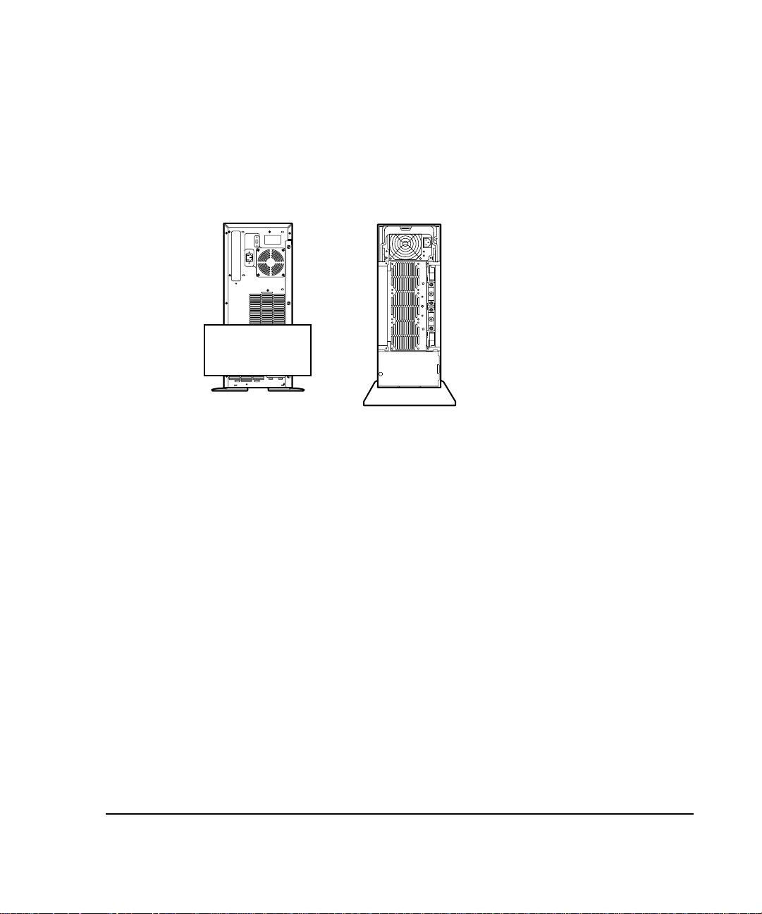
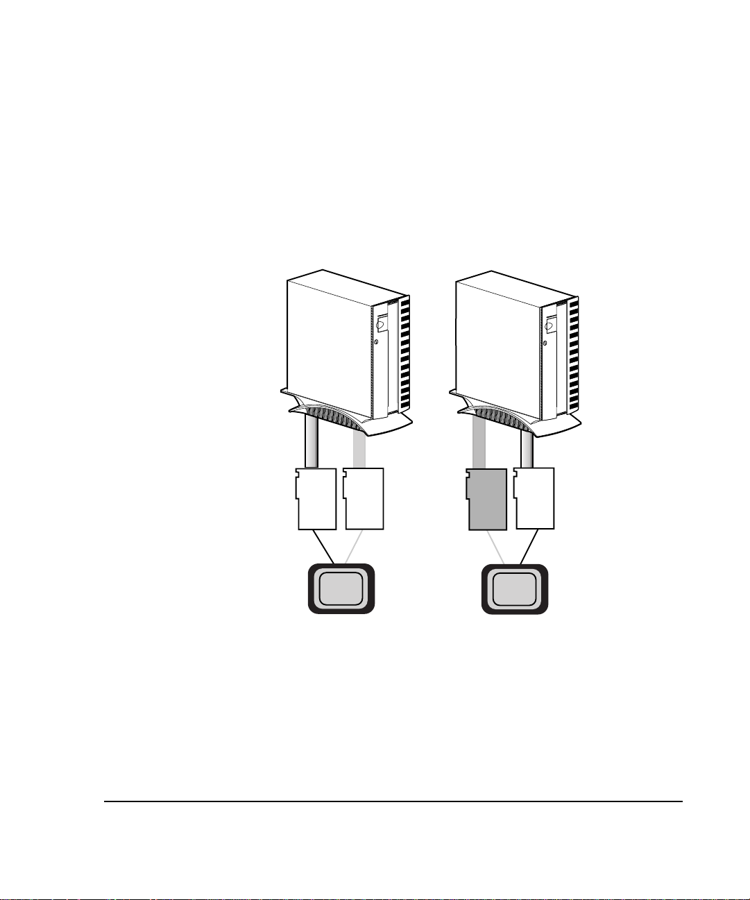
NOTE: OSCRO is supported for the single bus versions of the ProLiant Storage
System/F and /U units, in both the tower and rack-mount configurations. Older
ProLiant Storage Systems and duplex versions of the ProLiant Storage System are
not supported by OSCRO. The ProLiant Storage System/F and /U units that are and
are not supported are pictured in Figure 1-1.
Not
Supported
US Part Number 146700
189600
Intl. Part Number 146750
Figure 1-1.
197100
189640
197150
Compaq ProLiant Storage Systems
Software Requirements
OSCRO is supported only under Windows NT 4.0.
All software required to implement OSCRO is on the Compaq SmartStart and
Support Software CD included in the kit. This CD includes the Compaq Support
Software for Microsoft Windows NT (SSD) (version 2.02 or later) and updated
firmware and device drivers for the Compaq SMART-2 Array Controllers. For
instructions on how to build diskettes from the CD, see Appendix C “Building
Diskettes from the SmartStart and Support Software CD.”
US Part Number 272800
272900
304100-B21
304110-B21
Intl. Part Number 272804
272904
304104-B31
304114-B31
Page 17

. . . . . . . . . . . . . . . . . . . . . . . . . . . . . .
1-3
The Compaq SSD for Windows NT includes the following elements required to
implement OSCRO:
Compaq Online Storage Controller Recovery Utility
■
Updated Compaq SMART-2 Array Controller device driver
■
(CPQARRAY.SYS)
■
■
OSCRO also requires installation of the Remote Procedure Call (RPC)
Service, which is part of the Windows NT operating system. If OSCRO is
also to be used to manage remote servers, you need to install a routable
protocol that supports RPC (such as TCP/IP).
The ROMPaq for the SMART-2 firmware upgrade (version 1.94 or later) is
included on the SmartStart and Support Software CD in the Recovery Server
Option /U kit. It can also be found on the Compaq Web site.
Kit Contents
The Recovery Server Option /U kit (part number 304117-B21) includes
hardware and software required for implementation of OSCRO and some
additional parts (that would be used if you were installing either the Standby
Recovery Server or On-Line Recovery Server option).
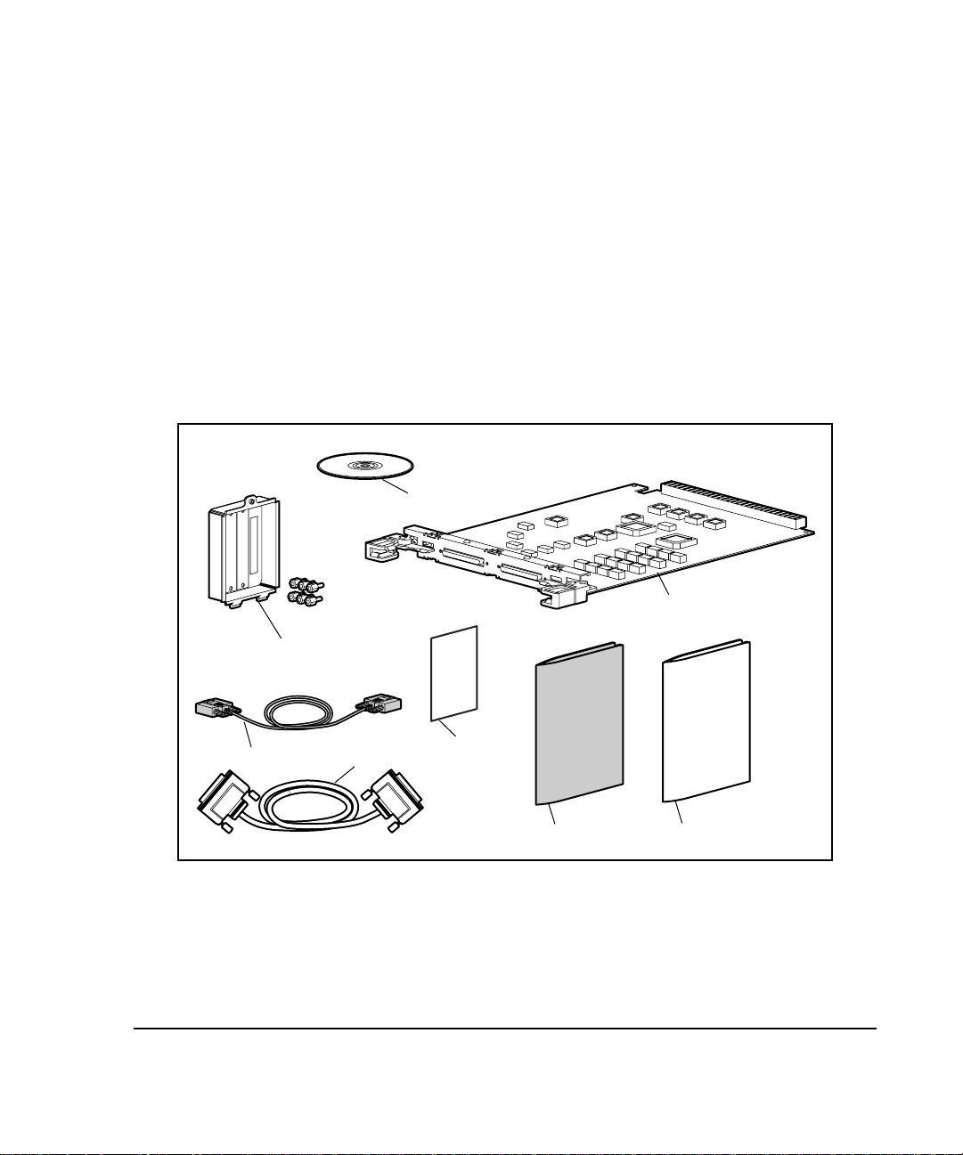
Check Figure 1-2 to verify that you have all of the necessary items for OSCRO
implementation. The items in the kit that relate to OSCRO are:
■
■
Compaq System Management driver
Compaq Remote Monitoring service
(SYSMGMT.SYS)
(CPQRCMC.EXE)
One Recovery Server Switch (part number 007678-001)
One Knockout Panel Assembly (part number 189620-001)
One External Fast-Wide SCSI Cable (part number 189646-003)
■
Compaq SmartStart and Support Software CD (part number 196268-
■
001), which includes all of the software and drivers required for the
Online Storage Controller Recovery Option
The
■
Online Storage Controller Recovery Option User Guide
Online Storage Controller Recovery Option User Guide
(this document)
Page 18
. . . . . . . . . . . . . . . . . . . . . . . . . . . . . .
1-4
Elements of the Online Storage Recovery Option Solution
The contents of the Recovery Server Option /U kit are illustrated in
Figure 1-2. When implementing OSCRO, not all of the parts in the kit will
be needed. Those that are not needed for OSCRO are shaded in the figure.
To implement OSCRO, you may also need one or more additional internal
SCSI ribbon cables (part number 199595-002). These are the original cables
that came with your SMART-2 Array Controllers. If you do not have the
correct cables and you are planning a dual-channel configuration (see
Chapter 2), you also need one or more Spares kits (part number 198639-
001). Spares kits include the required ribbon cable, screws, and screwlocks
required for OSCRO implementation.
Verify that you have all the necessary items before beginning the installation.
196268
007678
189620
213807
Figure 1-2.
189646
Kit Contents (Part Number 304117-B21)
Important
Card
RSO User Guide
OSCRO User Guide
After verifying that you have all the required elements for the OSCRO
implementation you are planning, proceed to Chapter 2 to learn more about
OSCRO.
Page 19

. . . . . . . . . . . . . . . . . . . . . . . . . . . . . .
2-1
Chapter 2
Functionality and Configuration
Options
There are three high-availability option solutions in the Recovery Server
Option /U kit:
■ Standby Recovery Server
■ On-Line Recovery Server
■ Online Storage Controller Recovery Option (OSCRO)
The first two option solutions minimize server downtime by automatically
transferring operations from a failed server to a backup server.
OSCRO, on the other hand, provides a way to reduce or eliminate downtime
associated with mass storage controller failure. In this chapter, we examine how
OSCRO provides this benefit.
Redundancy at the Mass Storage
Controller Level
In the past, the effort to improve the reliability of I/O subsystems focused on
redundant arrays of independent disks (RAID). RAID protects data if a disk
drive fails but offers no protection against mass storage controller failure.
Windows NT provides the option to implement a fully redundant I/O subsystem
in a configuration called Disk Duplexing. Disk Duplexing implemented at the
software level provides protection against failure of the disk as well as the mass
storage controller. Disk Duplexing requires complete redundancy of all I/O
subsystem components, however, which makes it very costly to implement and
limits the extensibility of the system.
With the introduction of OSCRO and its two-way switching capability,
Compaq offers fault tolerance for mass storage controllers implemented at the
hardware level, providing increased reliability without the need for complete
I/O subsystem redundancy.
Online Storage Controller Recovery Option User Guide
Page 20
. . . . . . . . . . . . . . . . . . . . . . . . . . . . . .
2-2
Functionality and Configuration Options
Merging two SMART-2 Controllers
into a Controlled Pair
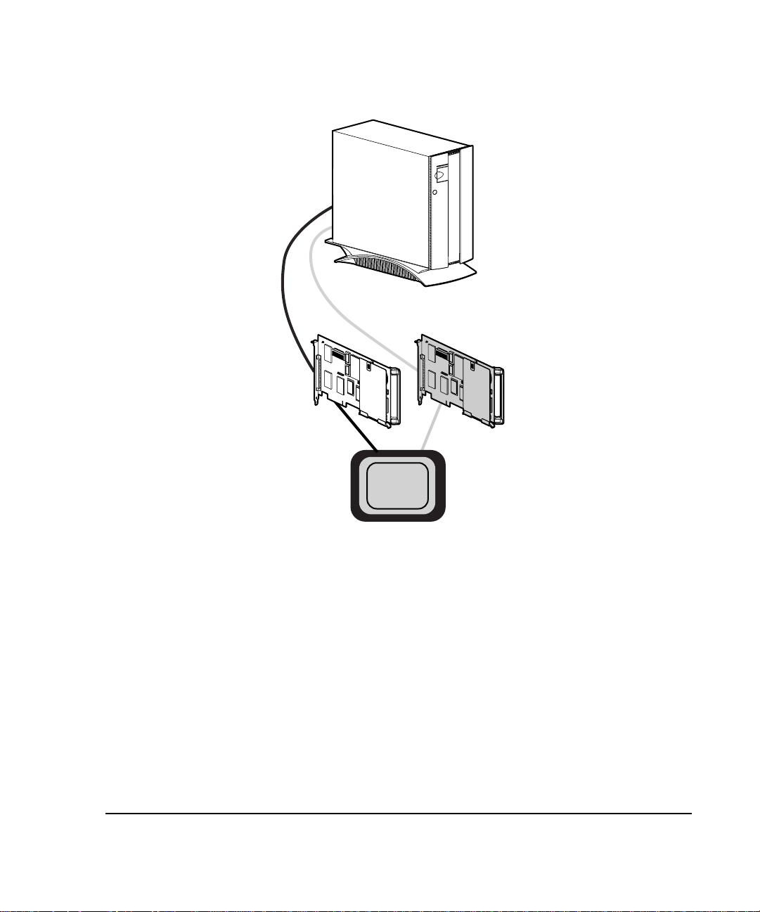
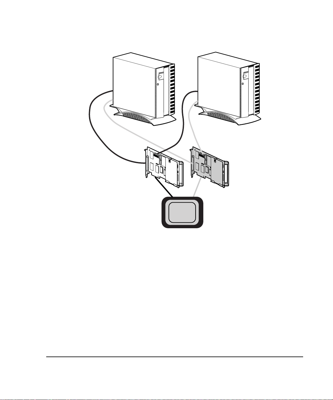
OSCRO allows you to merge two matched SMART-2 controllers into a
controller pair. In such a pair, one controller is active and the other remains
in standby mode. Should a problem occur with the active controller, the
SMART-2 device driver switches traffic to the standby controller without
loss of data or interruption of service (see Figure 2-1).
1
0
1
0
1
0
1
Figure 2-1.
Standby
Active
Device
Driver
A controller pair
is established.
Online Storage Controller Recovery Option Overview
If the active controller fails, the standby
Failed
controller is promoted to active.
Device
Driver
Active
Page 21

. . . . . . . . . . . . . . . . . . . . . . . . . . . . . .
2-3
Previously, implementing mass storage controller redundancy required
duplication of the mass storage controllers, as well as the disk drives. By
pairing OSCRO with RAID 5 arrays, you gain the benefits of fault tolerance for
the disks and the controllers without the additional costs of complete disk drive
redundancy.
OSCRO extends the reliability of Windows NT servers by ensuring continuing
operation of the system, even when a mass storage controller fails. The Compaq
Online Storage Controller Recovery Utility for Windows NT provides a means
of managing the mass storage controllers of the entire Windows NT network
from a single management station.
OSCRO is a natural partner for Compaq PCI Hot Plug technology. The
combination of the two eliminates the need to shut the system down when a
mass storage controller fails. OSCRO permits the system to continue operating
after a controller failure, and PCI Hot Plug technology allows replacement of
the failed controller without shutting the system down.
Online Storage Controller Recovery Option User Guide
Page 22

. . . . . . . . . . . . . . . . . . . . . . . . . . . . . .
2-4
Functionality and Configuration Options
Configuration Options
This section outlines the configuration guidelines involved in establishing
highly reliable I/O using OSCRO. Table 2-1 lists the RAID options available
and details the requirements and benefits of each option.
Table 2-1
Configuration Options
Raid
Level
0 No 1 1 0% No Data unavailable
0 Yes 2 1 0% No Data unavailable if
1 No 1 2 50% No Data unavailable if
1 Yes 2 2 50% Yes Complete
5 No 1 3 33% to 7% No Data unavailable if
5 Yes 2 3 33% to 7% Yes Complete
Controller
Pairing
Controllers
Required
Min. # of
Drives
Storage Space
Overhead for
Redundancy
Recommended Comments
if drive or
controller fails.
drive fails.
controller fails.
redundancy, high
overhead.
controller fails.
redundancy,
lowest overhead.
Page 23

. . . . . . . . . . . . . . . . . . . . . . . . . . . . . .
2-5
SMART-2 Array Controllers implement RAID fault tolerance at the hardware
level, eliminating the overhead associated with implementing RAID in the
software. Another advantage of implementing RAID at the hardware level is
the ability to apply any of the RAID configuration options to the system disk, as
indicated in Table 2-2.
Table 2-2
SMART-2 Array Controller Configuration Options
0 No Fault Tolerance Yes Maximum availability of storage, no
1 Drive Mirroring Yes Half the space given up for RAID overhead;
5 Distributed Data
Yes Lower percentage of space given up to RAID
Guarding
protection of data.
half of the mirror set can fail without data
loss. No system performance overhead, as
write operations are performed by
hardware. Recommended when data
availability is most important.
overhead; one device of the stripe set can
fail without data loss. System performance
may be improved by reducing disk latency.
Recommended when data availability, cost,
and performance are important criteria in I/O
subsystem design.
Using OSCRO with RAID 0 provides protection against failure of a SMART-2
Array Controller, but does not provide any data protection if a disk fails.
Online Storage Controller Recovery Option User Guide
Page 24

. . . . . . . . . . . . . . . . . . . . . . . . . . . . . .
2-6
Functionality and Configuration Options
The combination of OSCRO and RAID 1 provides all the advantages of
traditional disk duplexing. This combination provides the additional advantage
of implementing all the fault tolerance features at the hardware level, thus
eliminating the overhead associated with implementing fault tolerance in the
software.
Pairing redundant SMART-2 Array Controllers with RAID 5 disk arrays
provides the data protection of the RAID implementation and the fault tolerance
of redundant controllers.
Conceptually, there are two ways to configure an OSCRO implementation:
single channel and dual channel. OSCRO can also be set up in more complex
combinations of single-channel and/or dual-channel configurations.
Single-Channel Configuration
The simplest OSCRO configuration involves two SMART-2 Array Controllers
and a single ProLiant Storage System/F or /U equipped with the Recovery
Server Switch. The Compaq Online Storage Controller Recovery Utility is used
to merge the independent controllers into a controller pair. One controller is the
active controller, and the other is designated the standby controller. Both
controllers are physically wired to the ProLiant Storage System/F or /U through
the Recovery Server Switch, as illustrated in Figure 2-2.
Any two SMART-2 controllers with the same channel count can be used to
form a basic controller pair. When using a single-channel controller, such as the
SMART-2SL, the single-channel configuration is the only feasible OSCRO
configuration.
IMPORTANT:
installed from an earlier version of the Recovery Server Option kit, you must
disable that option, upgrade the Recovery Server Switch in the ProLiant
Storage System/F or /U, and reconfigure the cabling in order to implement
OSCRO. RSO and OSCRO cannot be implemented in the same devices at the
same time.
If you already have the Recovery Server Option (RSO)
Page 25
. . . . . . . . . . . . . . . . . . . . . . . . . . . . . .
2-7
ProLiant
Storage
System
1
/F or /U
2
Standby
Figure 2-2.
Active
Device
Driver
Single Controller Pair Configuration -- Logical Diagram
The single-channel configuration provides the foundation for understanding
how to configure OSCRO. Note that in the example shown in Figure 2-2, the
active controller is connected to the primary port on the ProLiant Storage
System.
The active controller should always be connected to the primary port of the
ProLiant Storage System to provide consistent recovery after complete power
loss to the server and the storage system. When the power is cycled on the
ProLiant Storage System, the Recovery Server Switch inside is reset and the
primary port becomes the active port by default. By aligning the primary port of
the ProLiant Storage System with the active controller of the controller pair, the
system recovers from a power failure using the power-up defaults.
Online Storage Controller Recovery Option User Guide
Page 26

. . . . . . . . . . . . . . . . . . . . . . . . . . . . . .
2-8
Functionality and Configuration Options
This configuration rule is especially significant when the system boot device is
connected to a controller pair. Because the boot device controller is selected
during System Configuration by setting the Controller Order to First, no other
controller can be used to boot the system. Therefore, the boot device controller
must be given default access to the ProLiant Storage System after power is
restored.
Dual-Channel Configuration
Dual-channel SMART-2 Array Controllers are capable of supporting two
ProLiant Storage Systems. A controller pair can support a pair of ProLiant
Storage Systems as long as the cabling is done properly. Figure 2-3 shows a
logical diagram of such a configuration.
When forming dual-channel controller pairs, both controllers must be dualchannel controllers. Do not attempt to use single-channel controllers such as the
SMART-2SL in a dual-channel configuration.
Page 27
. . . . . . . . . . . . . . . . . . . . . . . . . . . . . .
2-9
Figure 2-3.
ProLiant
Storage
System
1
/F or /U
2
1
Active
Device
Driver
Dual-Channel Controller Pair -- Logical Diagram
1
2
ProLiant
Storage
System
/F or /U
2
Standby
Multiple Controller Pairs
An OSCRO multiple controller pair configuration would be required in an
installation that needs mass storage controller redundancy for more than 14
spindles of data. A controller pair in a multiple controller pair configuration
can be a single-channel or dual-channel pair. The capability to define multiple
controller pairs extends the configurable size of the fault-tolerant I/O
subsystem. With increased flexibility comes an increased need for planning
and care during configuration and installation.
Online Storage Controller Recovery Option User Guide
Page 28

. . . . . . . . . . . . . . . . . . . . . . . . . . . . . .
2-10
Functionality and Configuration Options
The number of possible controller pairs may be limited by the number of
knockout panels or slots (see Figure 3-6) available on the server as well as the
number of available expansion slots for SMART-2 controllers. Some older
ProSignia servers have only one knockout panel with four slots. Such systems
are limited to implementing two dual-channel configurations.
NOTE
: Newer ProLiant servers have knockout slots built in to the case and do not
require installation of the knockout panel assembly.
Internal vs. External Boot Device
OSCRO implementation does not require you to include the boot device
controller in an OSCRO controller pair. There are advantages to doing so, and
there are advantages to not doing so.
Having the operating system on a drive protected by an OSCRO controller pair
protects the operating system as well as the data on the disks. There are,
however, boot device considerations with OSCRO. For a discussion of these,
see the “Boot Device Configuration Planning” section in Chapter 3.
One way to improve performance is to segregate system I/O traffic from
application I/O traffic. This can be achieved by creating a separate OSCRO
controller pair for the boot device controller, or by leaving the boot device
controller as a standalone device. When the embedded SCSI controller is used
as the boot device controller, segregation of I/O traffic is achieved, but OSCRO
does not allow use of the embedded SCSI controller in a controller pair.
Page 29

. . . . . . . . . . . . . . . . . . . . . . . . . . . . . .
3-1
Chapter 3
Planning and Installing the
Online Storage Controller
Recovery Option
To implement OSCRO, you must perform some or all of the following planning
and installation steps:
1. Plan the hardware configuration, taking related issues into account.
2. Install new controllers, if necessary. Minimally, you should label the cables
you will use for OSCRO and connect them based on the OSCRO
configuration you have selected.
3. Upgrade the SMART-2 controller firmware and device drivers.
4. Load the OSCRO software.
5. Use the Compaq Online Storage Controller Recovery Utility to merge
controllers in OSCRO controller pairs.
Hardware Planning
The first step toward OSCRO implementation is hardware planning. You must
have at least one Compaq ProLiant or ProSignia server, at least two
SMART-2 Array Controllers of the same type, and at least one Compaq
ProLiant Storage System/F or /U.
Controllers for OSCRO Implementation
There are two types of SMART-2 Array Controllers that can be made into
OSCRO redundant controller pairs. They are:
■ Single channel (SMART-2SL)
■ Dual channel (SMART-2/P, SMART-2/E, SMART-2DH)
Online Storage Controller Recovery Option User Guide
Page 30

. . . . . . . . . . . . . . . . . . . . . . . . . . . . . .
3-2
Planning and Installing the Online Storage Controller
CAUTION: SMART-2 Array Controllers use different disk geometries than
standard SCSI adapters. Consequently, disks cannot be interchanged
between SCSI adapters and SMART-2 Array Controllers without complete
loss of data on the disk.
Dual-Channel Configuration Considerations
You may want to consider a dual-channel OSCRO configuration when you
want mass storage controller redundancy for more than seven spindles of data.
There are a few things you should consider when planning for a dual-channel
OSCRO configuration or a multiple controller pair configuration that involves a
dual-channel controller pair. They are:
1. When forming dual-channel controller pairs, both controllers must be
dual-channel controllers. Do not attempt to use a single-channel
controller, such as the SMART-2SL, in a dual-channel configuration.
2. You may need a knockout panel(s) (see Figure 3-6) on the back of the
server where the External Wide SCSI connectors will be mounted. If the
knockout panel has no slots, you can replace it with the knockout panel
included in the Recovery Server Option /U kit. Newer ProLiant servers
are equipped with knockout slots and thus do not require knockout panel
installation
Knockout Panels
The number of possible controller pairs in your OSCRO implementation may
be limited by the number of knockout panels or slots available on the server.
Some older ProSignia servers have only one knockout panel with four slots.
Such systems are limited to implementing two dual-channel OSCRO
configurations. Some servers have integrated knockout slots rather than
knockout panels.
IMPORTANT: Some older ProSignia systems do not have any knockout
panels and cannot be used in dual-channel OSCRO implementations.
Page 31

. . . . . . . . . . . . . . . . . . . . . . . . . . . . . .
3-3
OSCRO Planning Implications
There are several things to consider before installing OSCRO. They include
thinking about your current environment in terms of the following:
■ The Recovery Server Option /U kit contains parts for three different
high-availability option solutions. Because these are mutually exclusive
options, if you are going to implement OSCRO and you already have
either Standby Recovery Server or On-Line Recovery Server installed
on your existing server, you need to de-install the Recovery Server
Option now in place.
■ If you have a duplexed ProLiant Storage System/F or /U, you may not
want to implement OSCRO, because OSCRO does not support duplexed
storage systems. If you decide to implement OSCRO, you will need to
de-install the duplexed ProLiant Storage System and potentially rebuild
all of your disk arrays and logical drives.
■ If you have an older ProLiant Storage System, you need to upgrade to
the ProLiant Storage System/F or /U.
■ For each upgrade of Windows NT or device drivers, the OSCRO
controller pairs must be dissolved before the upgrade, and re-established
after the upgrade is completed.
Upgrading controllers requires dissolving and re-merging OSCRO controller
pairs only when you are upgrading the device drivers or switching from
single-channel to dual-channel controllers. Upgrading from SMART-2/P to
SMART-2DH, for example, has no direct impact on an OSCRO controller
pair. Moving controllers to different PCI or EISA slots, on the other hand,
requires dissolving and re-merging a controller pair.
Online Storage Controller Recovery Option User Guide
Page 32

. . . . . . . . . . . . . . . . . . . . . . . . . . . . . .
3-4
Planning and Installing the Online Storage Controller
Potential Impact on Unattended Reboot
Installation of OSCRO effectively sets up a standby mass storage controller.
Consequently, in an OSCRO implementation, at least one of the SMART-2
Array Controllers on the system is not electrically connected to the ProLiant
Storage System at boot time. This condition, which is detected during Power
On Self Test (POST), causes the system to prompt for the system administrator
to press F1 to continue or F10 to run system partition utilities. Because this
prompt does not time out, unattended reboots may be inhibited.
To facilitate unattended reboots, disable the F1 Boot Prompt using the System
Configuration Utility before OSCRO is installed. For detailed instruction on
how to do this, see the “Installing the Controllers” section later on in this
chapter. It is also recommended that you retain the bootable System
Configuration disk to facilitate subsequent configuration changes.
Boot Device Configuration Planning
Connecting the boot device to a controller pair requires careful planning. Only
the primary mass storage controller, designated First in Controller Order by
the System Configuration Utility, can act as the boot device controller.
When configuring a boot device in an OSCRO controller pair, keep in mind
that:
■ The primary mass storage controller must be the active controller of the
controller pair at boot time.
■ The primary mass storage controller must be connected to the port of the
ProLiant Storage System/F or /U that activates immediately after
powering up the ProLiant Storage System. In a tower system, this is the
top port; in a rack-mount, it is the left port as you face the back of the
system.
This configuration provides fault tolerance for the boot device controller, which
enables the server to continue operating even if the primary mass storage
controller fails.
Page 33

. . . . . . . . . . . . . . . . . . . . . . . . . . . . . .
3-5
Array Acceleration Disabled
To ensure data integrity in the event of controller failure, implementing
OSCRO automatically disables the Array Accelerator feature of the SMART-2
Array Controller. This preserves coherency between the controllers in case of a
failovera switch from the active (failed) controller to the standby controller.
Under no circumstances should array acceleration be enabled on a SMART-2
Array Controller that is a member of an OSCRO controller pair.
The system performance implications of disabling the array accelerator vary
according to the application type and load placed on the system.
Recovery Server Option Incompatibility
Compaq Recovery Server Option consists of the Standby Recovery Server and
the On-Line Recovery Server. OSCRO cannot be run in conjunction with either
Recovery Server Option because both require hardware connectivity to
ProLiant Storage Systems through the same interfaces and, although the cables
are the same type, the cabling requirements are not compatible.
Setting Up for OSCRO Installation
There are several tasks that need to be accomplished to fully implement the
Online Storage Controller Recovery Option. They include:
1. Installing the Recovery Server Switch in the ProLiant Storage System/F
or /U
2. Upgrading the SMART-2 Array Controller firmware
3. Updating the SMART-2 device drivers
4. Loading the OSCRO software from the Compaq Support Software for
Microsoft Windows NT (SSD)
Online Storage Controller Recovery Option User Guide
Page 34

. . . . . . . . . . . . . . . . . . . . . . . . . . . . . .
3-6
Planning and Installing the Online Storage Controller
These tasks, which should be performed in the order presented, are described in
this section. You will need diskettes for step 2. Steps 3 and 4 can be done
directly from the SmartStart and Support Software CD. If you do not have the
diskettes required for Step 2, see Appendix C, “Building Diskettes from the
SmartStart and Support Software CD,” for instructions on how to create them.
Installing the Recovery Server Switch in the
ProLiant Storage System/F or /U
The Recovery Server Switch must be installed in the ProLiant Storage
System/F or /U that will be controlled by an OSCRO pair. The switch fits in
either a tower or rack-mount ProLiant Storage System/F or /U. Installation
differs, as described in the next sections.
Switch Installation in a Tower
To install the Recovery Server Switch in a tower ProLiant Storage System/F
or /U:
1. Make sure the power switch on the ProLiant Storage System is turned off.
2. Looking at the back of the ProLiant Storage System/F or /U, locate the
Fast-Wide SCSI interface module. Press the release tabs and remove the
module as shown in Figure 3-1.
Page 35

. . . . . . . . . . . . . . . . . . . . . . . . . . . . . .
3-7
FIG059.EPS
Figure 3-1.
Removing the Fast-Wide SCSI Interface Module in a Tower Server
3. Carefully slide in the Recovery Server Switch (Part Number 007678-001)
as shown in Figure 3-2. Close the release tabs to lock the module in place.
FIG060.EPS
Figure 3-2.
Sliding in the OSCRO Switch in a Tower Server
Online Storage Controller Recovery Option User Guide
Page 36

. . . . . . . . . . . . . . . . . . . . . . . . . . . . . .
3-8
Planning and Installing the Online Storage Controller
Switch Installation in a Rack Mount
To install the Recovery Server Switch in a rack-mount ProLiant Storage
System/F or /U:
1. Make sure the power on the ProLiant Storage System is turned off.
2. Looking at the back of the ProLiant Storage System, locate the original
Fast-Wide SCSI interface module. Press the release tabs and remove the
module as shown in Figure 3-3.
FIG061.EPS
Figure 3-3.
3. Carefully slide in the Recovery Server Switch (part number 007678-001)
Removing the Fast-Wide SCSI Interface Module in a Rack-Mount Server
as shown in Figure 3-4. Close the release tabs to lock the module
into place.
Page 37

. . . . . . . . . . . . . . . . . . . . . . . . . . . . . .
3-9
FIG062.EPS
Figure 3-4.
Sliding in the Recovery Server Switch in a Rack-Mount Server
Upgrading the SMART-2 Array Controller
Firmware
The firmware upgrade for SMART-2 Array Controllers is on the Compaq
SmartStart and Support Software CD. To upgrade the firmware, follow the
instructions on the ROMPaq (version 2.39, which contains SMART-2 Array
Controller firmware 1.94), heeding all of the warnings and restriction
instructions. If you have previously upgraded your firmware to a version above
1.94, do not do this upgrade. For more information about the firmware, please
refer to the white paper “Implementing Online Storage Controller Recovery
Option Under Windows NT,” available on the Compaq Web site.
If you do not have the diskettes required for this upgrade, see Appendix C,
“Building Diskettes from the SmartStart and Support software CD” for
instructions on how to create them.
Online Storage Controller Recovery Option User Guide
Page 38

. . . . . . . . . . . . . . . . . . . . . . . . . . . . . .
3-10
Planning and Installing the Online Storage Controller
Updating the SMART-2 Array Controller
Device Drivers
Updated device drivers for the SMART-2 Array Controllers are on the
Compaq SSD for Windows NT (version 2.02 or later), which is on the
Compaq SmartStart and Support Software CD included in the Recovery
Server Option /U kit. Instructions for installing the Compaq SSD for
Windows NT are given below.
Loading the Compaq SSD for Windows NT
The software required for OSCRO is included on the Compaq SSD for
Windows NT, which is on the Compaq SmartStart and Support Software CD
included in the kit.
The Compaq SSD for Windows NT also provides the updated Compaq Remote
Monitor Service and the System Management driver, both of which are
required for OSCRO.
Run SETUP.EXE from CPQSUPSW\NTSSD. When the Setup Utility for the
Compaq SSD for Windows NT is running, the screen shown in Figure 3-5 is
displayed. This screen lists the options available. To install OSCRO, highlight
the Compaq Online Storage Controller Recovery line and click the Install or
Update button.
Page 39

. . . . . . . . . . . . . . . . . . . . . . . . . . . . . .
3-11
Figure 3-5.
The screen shown in Figure 3-5 shows all of the components provided by the
Compaq SSD for Windows NT. Table 3-1 describes the components that are
and are not required for implementing the Online Storage Controller Recovery
Option.
Compaq SSD for Windows NT Setup Screen
Online Storage Controller Recovery Option User Guide
Page 40

. . . . . . . . . . . . . . . . . . . . . . . . . . . . . .
3-12
Planning and Installing the Online Storage Controller
Table 3-1
Compaq SSD for Windows NT Components
SSD Component Required
for
OSCRO
Uniprocessor/Multiprocessor
HAL and Kernel
HAL Recovery Option
Compaq System Management
Driver
Compaq Remote Monitor
Service
Compaq PCI Hot Plug
Continued
No
No
Yes
Yes
No
Allows you to upgrade or downgrade the HAL and kernel to match
the configuration of the server.
Allows a user with a multiprocessor system to recover from bluescreen traps resulting from mismatched HAL and hardware,
mismatched HAL and kernel, and HAL corruption. Although not
required for OSCRO, it is highly recommended for multiprocessorcapable servers.
This component is required on the local server when implementing
OSCRO. It provides a communications path between the SMART-2
device drivers and the Compaq Online Storage Controller Recovery
Utility.
The CPQRCMC service is required when implementing OSCRO on
the local server or when setting up remote management capability.
CPQRCMC acts as the central communications point for the Compaq
Online Storage Controller Recovery Utility as well as the PCI Hot Plug
Utility.
The PCI Hot Plug utility allows you to control the PCI Hot Plug slots
on the local system or on a remote system. Although not required
for OSCRO, it is useful in the OSCRO environment to prevent
downtime.
Description
Page 41

. . . . . . . . . . . . . . . . . . . . . . . . . . . . . .
3-13
Compaq SSD for Windows NT Components
SSD Component Required
for
OSCRO
Compaq Online Storage
Controller Recovery Utility
Compaq Fast SCSI-2
Controller
Compaq SMART-2 Array
Controller
Compaq ProLiant Storage
System
Compaq Netelligent/NetFlex-3
Network Controller(s)
Power Down Manager No Controls the intelligent power down switch in newer ProLiant
Yes
No
Yes
No
No
Continued
Description
The Online Storage Controller Recovery Utility manages OSCRO on
the local system and on remote systems.
Device drivers for Compaq SCSI-2 controllers.
Updated device drivers for Compaq SMART-2 Array Controllers are
required to implement OSCRO on the local server.
Provides support for Compaq ProLiant Storage Systems only when
attached to Compaq SCSI-2 controllers.
Device drivers for Compaq network controllers.
servers.
Using the Express option directs Setup to detect the devices and software
options installed on your system that could be updated with the newer versions
on the Compaq SSD for Windows NT. After clicking the Express button, a
screen is displayed that shows the options Setup will install. From this screen
you can select or deselect any of the options shown.
Installation
Although some of the OSCRO installation steps may already have been
completed on your system, all of the steps required for OSCRO implementation
are detailed in this section. The basic steps are:
■ Installing and configuring the hardware
■ Configuring the SMART-2 Array Controllers
Online Storage Controller Recovery Option User Guide
Page 42

. . . . . . . . . . . . . . . . . . . . . . . . . . . . . .
3-14
Planning and Installing the Online Storage Controller
■ Installing the OSCRO software
■ Making one or more controller pairs
If the controllers you will be using for OSCRO are already installed and
configured, go to the next section, “Labeling the Cables.”
Installing the Controllers
The SMART-2 Array Controllers must be installed and configured using the
Array Configuration Utility. For additional information, refer to the SMART-2
Array Controller Installation Guide that came with the controllers you will be
using for OSCRO.
To install SMART-2 Array Controllers:
1. Back up the entire data environment of the server.
2. Shut down Windows NT, and power down the server.
3. Insert the SMART-2 controller(s) necessary for your OSCRO
configuration into available PCI slot(s).
4. Power up the system.
5. Boot the system into the System Configuration Utility (version 2.34A or
above) using the System Configuration diskette built from the SmartStart
and Support Software CD included in the kit. If you do not have the
diskettes required for this step, see Appendix C, “Building Diskettes from
the SmartStart and Support Software CD,” for instructions on how to create
them.
6. Disable the F1 Boot Prompt using the Advanced Mode of the System
Configuration Utility by performing these steps:
❏ After passing through the initial screen(s), the Main Menu is
displayed. Press Ctrl + A. A notice pops up stating that Advanced
Mode is enabled.
❏ On the Main Menu, select System Configuration.
Page 43

. . . . . . . . . . . . . . . . . . . . . . . . . . . . . .
3-15
❏ On the System Configuration Menu, select Configure Hardware.
❏ When the automatic configuration is completed, you are given the
option to Save changes and exit, or Review and modify hardware
settings. Select Review and modify hardware settings.
❏ On the Steps in Configuring Your Computer menu, select Step 3:
View or edit details. Scroll down to the Advanced Features section
and locate the option labeled F1 Boot Prompt. Select that option
and press Enter to change it.
❏ Select Disabled - Skip Prompt and press Enter.
❏ Scroll down to the device that is to be the boot device controller.
Locate the parameter called Controller Order and press Enter. On
the pop-up menu that is displayed, select First and press Enter. A
warning that the controller previously marked as First is being
reconfigured is displayed.
❏ Press F10 and then save the system settings.
7. Press Enter to reboot the server.
Labeling the Cables
Cables should be marked to indicate proper orientation and allow visual
verification when you have completed implementation.
You should label the cables in a way that is specific to your implementation of
OSCRO. One example would be to mark the cables and the ports based on the
example in Table 3-2.
Online Storage Controller Recovery Option User Guide
Page 44

. . . . . . . . . . . . . . . . . . . . . . . . . . . . . .
3-16
Planning and Installing the Online Storage Controller
Table 3-2
Cable Labeling Example
Cable Label Description
AI-1
Active controller, Internal interface, first controller pair
AX-1
BI-1
BX-1
More complex configurations would use more than one cable of each type.
Following our example, you would increment the sequence number for each
controller pair.
Connecting the Cables
Cable connection is based on the OSCRO configuration selected during the
planning process.
Single-Channel Configuration
For a single controller-pair configuration, connect the cable from the external
ports of the SMART-2 controllers to the ProLiant Storage System
connectors, connecting the active controller to the primary port. In a tower
system, this is the top port; in a rack-mount, it is the left port as you face the
back of the system.
Dual-Channel Configuration
Active controller, External interface, first controller pair
Backup controller, Internal interface, first controller pair
Backup controller, External interface, first controller pair
To implement a dual-channel OSCRO configuration, perform the following
steps:
1. Shut down Windows NT, and turn off the power to the server.
Page 45

. . . . . . . . . . . . . . . . . . . . . . . . . . . . . .
3-17
2. Depending on which server you have, you may need to look on the back of
the server case and locate the knockout panel or the plate that covers the
hole for the knockout panel. Unscrew the top screw and remove the unit as
shown in Figure 3-6. If your server case has integrated knockout slots,
expose two of them and skip to step 4.
1
2
3
4
Figure 3-6.
Removing the Knockout Panel Unit
3. Using either the knockout panel included with the Recovery Server
Option /U kit or the one removed from the server, remove two of the
plates as above, exposing the slots.
4. Locate the internal ribbon cables (part number 199595) and the black
case mount bolts. Attach the cables to the external SCSI slots as shown
in Figure 3-7.
Online Storage Controller Recovery Option User Guide
Page 46

. . . . . . . . . . . . . . . . . . . . . . . . . . . . . .
3-18
Planning and Installing the Online Storage Controller
1
2
3
4
Stripe
Figure 3-7.
Attaching the Ribbon Cable to the External SCSI Slot
5. When all internal ribbon cables are connected to the knockout panel (if
you used a knockout panel), install it on the server and bolt it into place
with the black case mount bolts. If your server case has integrated
knockout slots, skip this step.
6. Connect the internal ribbon connectors to the internal ports of the dual-
channel SMART-2 controllers (see Figure 3-8).
7. Label the ports on the knockout panel so that it is easy to distinguish
which connector is connected to each of the SMART-2 controllers.
Page 47

. . . . . . . . . . . . . . . . . . . . . . . . . . . . . .
3-19
Internal
Connector
External
Connector
Figure 3-8.
Dual-Channel SMART-2 Array Controller Connectors
8. Locate the four external cables used to connect the server to the
ProLiant Storage Systems (part number 189646-003).
CAUTION: It is extremely important that the cables be connected
correctly. Incorrect cabling could nullify the effectiveness of OSCRO and
could result in data loss or disk unavailability.
9. Make sure that both ends of the external cables are labeled to avoid
confusion.
10. Connect the external connector from the active SMART-2 controller to
the first interface on the primary ProLiant Storage System.
11. Connect the internal interface from the active controller to the first
interface on the secondary ProLiant Storage System.
12. Connect the external connector from the standby SMART-2 controller to
the second interface on the primary ProLiant Storage System.
13. Connect the internal interface from the standby controller to the second
interface on the secondary ProLiant Storage System.
Online Storage Controller Recovery Option User Guide
Page 48

. . . . . . . . . . . . . . . . . . . . . . . . . . . . . .
3-20
Planning and Installing the Online Storage Controller
Merging Two Controllers into a Controller Pair
To make a controller pair:
1. Access the Compaq Online Storage Controller Recovery Utility by
double-clicking the Compaq Online Storage Recovery applet in the
Control Panel, or in the Compaq System Tools folder.
2. Confirm that the controllers you want to merge are properly connected
to the ProLiant Storage System using theRecovery Server Switch. While
verifying the connection, make note of the physical slot number of the
controllers connected to the ProLiant Storage System. This eliminates
any possible confusion when performing the merge operation.
3. When you are certain the connections are correct, select one of the two
controllers by clicking it. Hold down the Ctrl key and click the second
controller you want to be part of the pair. Doing so highlights both
selected controllers and activates the Merge button, as shown in
Figure 3-9.
Figure 3-9.
Merging Two Controllers Into a Controller Pair
Page 49

. . . . . . . . . . . . . . . . . . . . . . . . . . . . . .
3-21
4. Click the Merge button to continue the process. The Compaq Online
Storage Controller Recovery Utility prompts you to confirm the decision
to merge the two controllers by displaying the dialog box shown in
Figure 3-10.
Figure 3-10.
5. By clicking the Yes button, you complete the merge operation; the
Merge Confirmation Dialog Box
controller pair is formed. Figure 3-11 shows the Compaq Online Storage
Controller Recovery Utility with an active controller pair.
Online Storage Controller Recovery Option User Guide
Page 50

. . . . . . . . . . . . . . . . . . . . . . . . . . . . . .
3-22
Planning and Installing the Online Storage Controller
Figure 3-11.
The active controller icon is green; the standby controller icon is gray. The icon
for the controller pair is white.
Merge Completed and Pair Active
Testing and Verifying the Installation
The last step of the OSCRO installation is to perform a Verify function on each
controller pairif you have not already done so. To Verify an OSCRO
controller pair, perform these steps:
1. Right-click the controller pair (the line with the white icon on the left), and
select Verify.
2. In a minute and a half or so, you either see a controller marked with a red
X (indicating failure) or the screen returns to its normal state (indicating
success).
Page 51

. . . . . . . . . . . . . . . . . . . . . . . . . . . . . .
3-23
3. If failure is indicated, make sure the cables are all attached and correctly
configured, then rerun the Verify process.
The Verify function in the Compaq Online Storage Controller Recovery Utility
takes over 80 seconds. During this process, all three icons have yellow X’s over
them indicating the controllers and the pair are Not Ready for use. As the test
progresses, each yellow X is removed, indicating that the configuration has
been deemed valid, or one or more yellow Xs are replaced by a red X,
indicating a cable fault. When the test concludes, the primary controller is
returned to active status.
IMPORTANT: If your configuration does not Verify and/or does not look
like one of the configurations described in Chapter 2, see Chapter 5,
“Troubleshooting.”
Online Storage Controller Recovery Option User Guide
Page 52

. . . . . . . . . . . . . . . . . . . . . . . . . . . . . .
4-1
Chapter 4
Compaq Online Storage
Controller Recovery Utility
The Compaq Online Storage Controller Recovery Utility is used to manage
OSCRO controller pairs.
This utility can be accessed from the Compaq Online Storage Recovery
applet in either the Control Panel or the Compaq System Tools folder. Each
SMART-2 Array Controller is displayed showing its controller type and its
physical location. The color of the icon indicates whether it is part of a
controller pair.
The Compaq Online Storage Controller Utility includes a browser that allows
you to configure and manage the mass storage controllers on the entire network
from a single management station. This browser works like the Network
Neighborhood function of Windows NT.
Major Functions
The primary functions of the Compaq Online Storage Controller Recovery
Utility are Merge, Dissolve, Properties, Browse, Refresh, and Help.
Merge combines two like controllers into an OSCRO controller pair.
Dissolve splits an OSCRO controller pair into two independent controllers.
Properties provides detailed information about controllers.
Browse locates other systems on the network and allows you to manage them
remotely. You must have a privileged account on the remote node in order to
manage the mass storage controllers on that system.
Refresh forces the main screen of the Compaq Online Storage Controller
Recovery Utility to update its information display.
Help provides online help on use of the Compaq Online Storage Controller
Recovery Utility and configuring OSCRO controller pairs.
Online Storage Controller Recovery Option User Guide
Page 53

. . . . . . . . . . . . . . . . . . . . . . . . . . . . . .
4-2
Compaq Online Storage Controller Recovery Utility
Right-Click Functionality
In addition to the primary functions, the Compaq Online Storage Controller
Recovery Utility provides several secondary functions that are available by
right-clicking the mouse button on a selected controller or controller pair.
Figure 4-1.
Figure 4-2.
As shown in Figures 4-1 and 4-2, the specific functions offered by the rightclick depend on whether the highlighted device is a controller or a controller
pair. The functions available for a controller are Fail/Unfail, Merge, and
Properties.
Fail / Unfail can be used to manually fail or unfail a controller.
Merge combines two like controllers into a controller pair. This is the
functional equivalent of the Merge button on the screen. This function is only
available when you highlight two controllers.
Right-Click Functions for Controllers
Right-Click Functions for Controller Pairs
Page 54

. . . . . . . . . . . . . . . . . . . . . . . . . . . . . .
4-3
Properties provides detailed information abut an individual controller. This
function is not available when a controller pair is selected. More detail of this
function is given in the “Viewing Device Properties” section below.
The functions available on a controller pair are Dissolve, Switch, and Verify.
Dissolve splits an OSCRO controller pair into two independent controllers.
This is the functional equivalent of the Dissolve button on the screen.
Switch performs a manual switch, promoting the standby controller of a
controller pair to active status. This function provides a way to switch which
controller is active.
Verify performs two Switch operations in order to verify that both controllers
of the controller pair are capable of becoming active, and that the cables are
physically connected.
Mass Storage Controller Icons
There are eight different mass storage controller icons that display on the left
side of Compaq Online Storage Controller Recovery Utility main screen.
Table 4-1 describes each icon.
Online Storage Controller Recovery Option User Guide
Page 55

. . . . . . . . . . . . . . . . . . . . . . . . . . . . . .
4-4
Compaq Online Storage Controller Recovery Utility
Table 4-1
Mass Storage Controller Icons
Controller
Icon
Color Description
Green Mass storage controller currently connected to
logical drives. Also indicates active controller in
controller pair.
Gray Mass storage controller not currently connected
to logical drives. Also indicates standby
controller in controller pair.
White Controller pair.
Black Mass storage controller is powered off.
Green
with
Yellow X
Gray
with
Yellow X
Green
with
Red X
Gray
with
Red X
Failed mass storage controller is not ready but
is connected to logical drives.
Failed mass storage controller that is not ready
and is not connected to logical drives.
Failed mass storage controller that is connected
to logical drives.
Failed controller with no logical units or drivers,
or a failed standby controller in an OSCRO pair.
Page 56

. . . . . . . . . . . . . . . . . . . . . . . . . . . . . .
4-5
Figure 4-3 shows the main screen of the Compaq Online Storage Controller
Recovery Utility when two SMART-2 controllers are connected to a ProLiant
Storage System/F or /U through the Recovery Server Switch. One shows an
active connection (green), while the other shows an inactive connection (gray).
Figure 4-3.
When a controller pair is formed, a new icon representing the union of the two
individual controllers is displayed.
The normal controller pair icon is white. When a controller fails, the white icon
is covered with a red X. If there is no power to either controller in the pair, the
icon is black. If both controllers are failed or one is failed and the other has no
power, a white icon appears with a red X over it. If one of the controllers is not
ready or failed (this is the state during a Verify), the white icon for the pair is
covered with a yellow X. You also see a yellow X if one of the controllers in a
pair requires action to get OSCRO to a ready state.
Compaq Online Storage Controller Recovery Utility Main Screen
Online Storage Controller Recovery Option User Guide
Page 57

. . . . . . . . . . . . . . . . . . . . . . . . . . . . . .
4-6
Compaq Online Storage Controller Recovery Utility
These icons are shown in Table 4-2. This table shows how the status of the
individual controllers affects the status of the icon representing the controller
pair.
Table 4-2
Status Icons for Controller Pairs
Status of Controller #1 of a Controller Pair
Power Off Failed Not Ready Normal
Status of Power off
Controller #2 Failed
of a Controller Not Ready
Pair Normal
Viewing Device Properties
When a specific mass storage controller is selected on the Compaq Online
Storage Controller Recovery Utility screen, the General and Status properties of
that controller can be displayed. Selection can be made by double-clicking a
specific controller or selecting the Properties function on the right-click menu.
Select the tab based on the properties you want to see.
Page 58

. . . . . . . . . . . . . . . . . . . . . . . . . . . . . .
4-7
The General properties screen shown in Figure 4-4 provides information about
the physical and logical locations of the device. The board name, device driver
name, and the physical I/O address are also provided.
Figure 4-4.
General Properties Screen
Online Storage Controller Recovery Option User Guide
Page 59

. . . . . . . . . . . . . . . . . . . . . . . . . . . . . .
4-8
Compaq Online Storage Controller Recovery Utility
The Status properties page shown in Figure 4-5 provides information about the
status of the PCI Hot Plug slot (when applicable) and the mass storage
controller. The screen below shows the Status properties page of a device that is
not plugged into a PCI Hot Plug slot.
Figure 4-5.
The status information includes the indicators described in Table 4-3.
NOTE
Power Fault are not valid on non-PCI Hot Plug slots or systems.
Status Properties Screen
: The PCI Hot Plug indicators Slot Lever Closed, Power, Board Present, and
Page 60

. . . . . . . . . . . . . . . . . . . . . . . . . . . . . .
4-9
Table 4-3
Status Properties Indicators
Slot Lever Closed Slot release lever is in the
closed position.
Power Power to the slot is turned on. Power to the slot is turned off.
Board Present A PCI adapter has been detected
in the slot.
Not Ready The PCI adapter is not ready for
software access.
Power Fault A power fault has occurred
on the slot.
Diagnostics Diagnostic tests are being
performed on the PCI adapter.
Failure: Failed The PCI adapter has failed. The PCI adapter is not reporting
Failure: Code Used for debugging device failures. No failure is reported.
Failure: Text The reason for failure is given. No failure is reported.
Failure The PCI adapter has failed. The PCI adapter is not reporting
Paired: No The PCI adapter is not part of a
controller pair.
Slot release lever is in the open
position.
No PCI adapter is detected
in the slot.
The PCI adapter is ready for
software access.
No power faults have occurred
on the slot.
No diagnostics are being run
on the PCI device.
a Failed status.
a Failed status.
The PCI adapter is part of a
controller pair.
Paired: Yes Active
Paired: Yes Standby
The PCI adapter is the
active member of a controller
pair.
The PCI adapter is the
standby member of a
controller pair.
The PCI adapter is not the
active member of a controller
pair.
The PCI adapter is not the
standby member of a controller
pair.
Online Storage Controller Recovery Option User Guide
Page 61

. . . . . . . . . . . . . . . . . . . . . . . . . . . . . .
4-10
Compaq Online Storage Controller Recovery Utility
Setting Machine Options
Right-clicking the title bar of the Online Storage Controller Recovery Utility
brings up the System menu for the utility. Selecting Options allows you to set
the General options.
The General options page, shown in Figure 4-6, allows you to disable
confirmations. Selecting this option prevents the display of the confirmation
dialog boxes when you perform an Online Storage Controller Recovery Utility
function.
Figure 4-6.
For additional information about the Online Storage Controller Recovery
Utility and how it works, please refer to the white paper entitled “Implementing
Online Storage Controller Recovery Option Under Windows NT,” available at
the Compaq Web site.
General Options Page
Page 62

. . . . . . . . . . . . . . . . . . . . . . . . . . . . . .
5-1
Chapter 5
Troubleshooting
If you are unable to perform a task associated with OSCRO, make sure you
have the privilege associated with the task. Other problems you encounter may
relate to reconfigured hardware or upgrading software related to OSCRO,
including Windows NT itself.
Controllers Must Be Matched
Setting up OSCRO requires that both members of a controller pair are capable
of sharing a single instance of the device driver. For this reason, the Online
Storage Controller Recovery Utility does not allow you to create a mismatched
controller pair.
Planning for OSCRO when RSO is in Use
Because the Standby Recovery Server, On-Line Recovery Server, and OSCRO
are mutually exclusive option solutions, an invalid configuration results from
implementing OSCRO when one of the other Recovery Server Options has
been installed and has not been de-installed.
It is also important to understand that the cabling for the Standby Recovery
Server and On-Line Recovery Server options is incompatible with OSCRO.
The cables are the same type but they must be reconfigured for OSCRO. If the
system already has one of the Recovery Server Options installed, you must
reconfigure the cabling before implementing OSCRO.
Incorrect Cabling
There are several ways to cable OSCRO configurations that may appear correct
but are incorrect. These cabling errors can lead to data loss if OSCRO is
implemented and a controller fails. The examples that follow involve crossconnected, unilateral, and mismatched cabling. These configuration errors must
be avoided.
Online Storage Controller Recovery Option User Guide
Page 63

. . . . . . . . . . . . . . . . . . . . . . . . . . . . . .
5-2
Configuration Errors to Avoid
It is important to understand that the Online Storage Controller Recovery
Utility detects cabling errors when the Verify function is used to test all OSCRO
controller pairs. If you are having a problem, run the Verify function.
Cross Connection
In the example shown in Figure 5-1, the cables are cross connected, that is, the
external connector from the active SMART-2 controller is attached to the same
ProLiant Storage System/F or /U as the internal connector of the standby
SMART-2 controller. The Online Storage Controller Recovery Utility may not
detect this error, and it may not manifest any problems until the switch occurs
from the active controller to the standby controller. When the active controller
fails with the cables this way, the system will not be able to locate the disks
because their logical SCSI port numbers will change.
Page 64

. . . . . . . . . . . . . . . . . . . . . . . . . . . . . .
5-3
1
2
ProLiant
Storage
System
/F or /U
1
Active
ProLiant
Storage
System
1
/F or /U
2
I N V A L I D
Device
Driver
2
Standby
Figure 5-1.
This configuration error demonstrates the need to pay close attention to the
labeling and cabling of OSCRO controller pairs. Although this error would be
detected by performing a Verify function, cabling errors such as this are most
likely to occur when the cables are not labeled properly. To avoid such errors,
see the “Labeling the Cables” section in Chapter 3.
Invalid Configuration -- Cross-Connected Cables - Logical Diagram
Online Storage Controller Recovery Option User Guide
Page 65

. . . . . . . . . . . . . . . . . . . . . . . . . . . . . .
5-4
Configuration Errors to Avoid
Unilateral Connection
In the example shown in Figure 5-2, both the internal and external cables from
the active controller are connected to the same ProLiant Storage System/F
or /U. Likewise, the internal and external cables from the standby controller are
connected to the second ProLiant Storage System/F or /U. This is also an error
that the Verify function of the Online Storage Controller Recovery Utility flags.
In addition, if there are drives in both ProLiant Storage Systems, both of the
SMART-2 controllers will be attached to active SCSI buses, and the Online
Storage Controller Recovery Utility will not allow the controllers to be merged.
In the unlikely event that no drives were installed in the second ProLiant
Storage System/F or /U, however, the Online Storage Controller Recovery
Utility does not detect this error unless the Verify function is used.
Page 66

. . . . . . . . . . . . . . . . . . . . . . . . . . . . . .
5-5
ProLiant
Storage
System
1
/F or /U
2
1
Active
ProLiant
Storage
System
1
/F or /U
2
I N V A L I D
Device
Driver
2
Standby
Figure 5-2.
This configuration error also highlights the need to label the interfaces attached
to the internal connectors of the SMART-2 controllers (as discussed in the
“Labeling the Cables” section in Chapter 3). The labels allow you to determine
which interface is connected to the active controller and which is connected to
the standby controller, without opening the system.
Invalid Configuration -- Unilateral Cabling - Logical Diagram
Online Storage Controller Recovery Option User Guide
Page 67

. . . . . . . . . . . . . . . . . . . . . . . . . . . . . .
5-6
Configuration Errors to Avoid
Mismatched Controller Pairs
OSCRO allows you to form multiple controller pairs in a single server. Each
controller pair must conform to the configuration guidelines for single-channel
or dual-channel controller pairs. Incorrect configurations can result from
connecting the cables incorrectly, as shown in Figure 5-3. Connecting the
secondary (idle) interface of the wrong ProLiant Storage System/F or /U, for
example, causes an incorrect configuration that the Online Storage Controller
Recovery Utility can detect only if you run a Verify. If you do not run a Verify,
you will be able to merge the controllers into a controller pair but the
configuration will not function if either of the active controllers fails.
Figure 5-3.
1
2
Active
ProLiant
Storage
System
/F or /U
1
Standby
1
2
ProLiant
Storage
System
/F or /U
2
Active
I N V A L I D
Device
Driver
Invalid Configuration -- Mismatched Controller Pairs - Logical Diagram
Device
Driver
Standby
Page 68

. . . . . . . . . . . . . . . . . . . . . . . . . . . . . .
5-7
Clearing a Cable Check Error
When using PCI Hot Plug technology, a Cable Check error can be cleared by
using the PCI Hot Plug Utility to cycle power to the PCI slot housing the failed
controller. Without PCI Hot Plug technology, the server must be rebooted to
clear a Cable Check.
Verify Does Not Switch Back
If you are running a Verify operation that does not perform both switch
operations and return the controller you have designated as the active controller
to that state, the most probable cause is that you are trying to install OSCRO
with a Recovery Server Switch that has not been upgraded. If you previously
implemented either Standby Recovery Server or On-Line Recovery Server,
check to see if the original Recovery Server Switch you installed is still in
place. If so, replace it with the Recovery Server Switch that came in the
Recovery Server Option /U kit.
Wrong Device Driver
If you get the message
unknown error 0xed0e0000
you are running with old device drivers. Use the Compaq SSD for
Windows NT that is included in the Recovery Server Option /U kit, to update
the controller device drivers.
Controller Not Seen on the Online
Storage Controller Recovery Utility
If the controller you are looking for does not appear on the Online Storage
Controller Recovery Utility main screen, it is probably not a controller
supported by OSCRO. Only the following SMART-2 Array Controllers can be
made into OSCRO redundant pairs: SMART-2SL, SMART-2/P, SMART-2/E,
and SMART-2DH.
Online Storage Controller Recovery Option User Guide
Page 69

. . . . . . . . . . . . . . . . . . . . . . . . . . . . . .
5-8
Configuration Errors to Avoid
Boot Device Considerations
After a controller failover, there are situations in which the system will not be
able to boot. If you get the following error message:
Non-system disk or disk error
Replace and strike any key when ready
you may be in the situation described in Chapter 6 under “Boot Device
Considerations.” The procedure for recovering from this situation is detailed
there.
Page 70

. . . . . . . . . . . . . . . . . . . . . . . . . . . . . .
6-1
Chapter 6
Recovering from Mass Storage
Controller Failure
OSCRO enables the server to continue operating even when a mass storage
controller fails. This section outlines the steps to replace a failed controller and
recover the fault-tolerant state of the I/O subsystem.
Recovering from mass storage controller failure differs depending on whether
the server utilizes PCI Hot Plug technology. If the controller that failed is your
boot device controller, you may need to take some action. You must make sure
the boot device controller is connected to the primary port of the ProLiant
Storage System/F or /U, that is, the one that is active after the power is cycled
on the ProLiant Storage System/F or /U.
When the power is cycled on the ProLiant Storage System/F or /U, the
Recovery Server Switch inside is reset and the primary port becomes the active
port by default. By aligning the primary port of the ProLiant Storage System/F
or /U with the active controller of the controller pair, the system recovers from
a power failure using the power-up defaults.
Recovering from Mass Storage
Controller Failure Using PCI Hot Plug
Technology
PCI Hot Plug technology and OSCRO work together to provide a means for
replacing a failed mass storage controller without shutting down the system.
The steps involved are:
1. Using the PCI Hot Plug Utility, power off the PCI slot containing the
controller.
2. Replace the controller.
3. Use the PCI Hot Plug Utility to power on the PCI slot containing the
replacement controller.
Online Storage Controller Recovery Option User Guide
Page 71

. . . . . . . . . . . . . . . . . . . . . . . . . . . . . .
6-2
Recoving from Mass Storage Controller Failure
4. Use the Online Storage Controller Recovery Utility to perform a manual
Switch operation, thus making the controller the active controller of the
controller pair (see Figure 6-1).
1
0
1
0
Active
1
0
1
Device
Driver
A controller pair
is established.
Figure 6-1.
Compaq PCI Hot Plug Technology Recovery from Controller Failure with OSCRO
Standby
1
0
1
Device
Driver
Active
1
0
1
Failed
If a controller fails,
standby becomes active.
controller removed.
1
0
1
Active
1
0
1
Device
Driver
PCI slot powered
down and failed
Standby
Active
1
Device
Driver
Controller replaced and
controller pair is
re-established.
Using this procedure, the fault-tolerant state of the I/O subsystem is restored
without shutting down the system or interrupting the availability of the data.
1
0
1
1
0
Page 72

. . . . . . . . . . . . . . . . . . . . . . . . . . . . . .
6-3
Recovering from Mass Storage
Controller Failure Without PCI Hot
Plug Technology
The steps for recovering from mass storage controller failure when you do not
have PCI Hot Plug Technology are:
1. Schedule a time when the server can be shut down.
2. Shut down the server at the scheduled time, and turn off the power.
3. Turn off the power to the ProLiant Storage System(s)/F or /U. This
resets the Recovery Server Switch.
4. Replace the failed controller.
5. Turn on the power to the ProLiant Storage System(s)/F or /U.
6. Reboot the server.
By following this procedure, the mass storage controller is replaced when
convenient for the System Administrator, restoring the I/O subsystem to a faulttolerant state.
Boot Device Considerations
A problem arises as a result of recovering from primary mass storage controller
failure without PCI Hot Plug technology in a specific case. The conditions that
present this case are:
1. The boot device controller is a member of a controller pair.
2. The boot device controller fails.
3. The backup controller takes over.
4. The server is shut down while the backup controller is acting on behalf
of the boot device controller.
5. The boot device controller is NOT repaired while the server is shut down.
Online Storage Controller Recovery Option User Guide
Page 73

. . . . . . . . . . . . . . . . . . . . . . . . . . . . . .
6-4
Recoving from Mass Storage Controller Failure
We strongly suggest you repair the boot device controller while the server is
shut down. If for some reason you cannot repair the boot device controller
while the server is shut down, the server will not be able to find the boot device;
the standby controller is not capable of acting as the boot device controller. To
recover from this situation, perform the following steps, assuming the failed
primary controller is Controller A and the standby controller is Controller B:
1. Turn off the power to the server.
2. Disconnect both cables from SMART-2 Array Controller B.
3. Move SMART-2 controller B into the slot previously occupied by the
primary controller (A). This step promotes the other SMART-2
controller (B) so it can act as the boot device controller. It does this by
positioning it in the slot designated as First in Controller Order.
4. Connect the external and internal cables for the primary controller (A) to
Controller B.
5. Cycle the power on the ProLiant Storage Systems to ensure that the
Recovery Server Switches inside are reset.
6. When the failed mass storage controller (A) is replaced, introduce it into
the configuration as the new backup controller.
7. Run the System Configuration Utility (version 2.34A or later) to specify
the new PCI/EISA bus configuration.
Performing these steps promotes the standby controller to the new boot device
controller and ensures its connection to the primary port of the ProLiant Storage
System/F or /U. These steps are necessary to allow the system to recover
cleanly from complete power failure.
Page 74

. . . . . . . . . . . . . . . . . . . . . . . . . . . . . .
7-1
Chapter 7
Dissolving a Controller Pair
OSCRO uses updated versions of the SMART-2 device drivers to establish and
maintain controller pair(s). Windows NT upgrades include default versions of
the device drivers built to be compatible with the versions of Windows NT
being installed. The device drivers included with the operating system,
however, may not be the same as those installed under previous versions of
Windows NT. For that reason, all controller pairs should be dissolved before
installing a Windows NT upgrade. These pairs can be re-merged after the
upgrade.
You will also want to dissolve OSCRO controller pairs before doing any device
driver or controller upgrades.
NOTE: Upgrading controllers only requires dissolving and re-merging OSCRO
controller pairs when it involves upgrading the device drivers or switching from
single channel to dual channel. Upgrading from SMART-2/P to SMART-2DH, for
example, has no direct impact on an OSCRO controller pair. Moving controllers to
different PCI or EISA slots, on the other hand, does require dissolving and remerging a controller pair.
CAUTION: When dissolving a controller pair, do not reconfigure the cables
until the pair is dissolved.
Dissolving a controller pair using the Online Storage Controller Recovery
Utility is easy. To dissolve a controller pair:
1. Make sure that the controller pair does not contain any failed controllers.
Controller pairs that include a failed controller cannot be dissolved until
the failed controller is repaired.
2. Access the Online Storage Controller Recovery Utility from the Compaq
Online Storage Recovery applet on the Control Panel, or from the Compaq
System Tools folder.
3. Highlight the controller pair you want to dissolve (the highlighted line
must have a white icon). This activates the Dissolve button.
Online Storage Controller Recovery Option User Guide
Page 75

. . . . . . . . . . . . . . . . . . . . . . . . . . . . . .
7-2
Dissolving a Controller Pair
4. Click the Dissolve button. A dialog box asks you to confirm that you want
to dissolve the controller pair (see Figure 7-1).
Figure 7-1.
5. Clicking the Yes button dissolves the controller pair, leaving you with two
Now you can perform the desired upgrade or reconfiguration.
Dissolve Confirmation Dialog Box
independent controllers.
CAUTION: Because one of the two array controllers is still electrically
disconnected from the ProLiant Storage System, it should be inactive (gray)
after dissolving the controller pair. You should not reconfigure the cabling
of the controllers until the controller pair has been dissolved.
Page 76

. . . . . . . . . . . . . . . . . . . . . . . . . . . . . .
A-1
Appendix A
Electrostatic Discharge
A discharge of static electricity from a finger or other conductor may damage
printed circuit boards or other static-sensitive devices. This type of damage may
reduce the life expectancy of the device.
Preventing Electrostatic Damage
To prevent electrostatic damage, observe the following procedures:
■ Avoid hand contact by transporting and storing parts in static-safe
containers.
■ Keep electrostatic-sensitive parts in their containers until they arrive at
static-free workstations.
■ Place parts on a grounded surface before removing them from their
container,
■ Avoid touching pins, leads, or circuitry.
■ Always be properly grounded when touching a static-sensitive
component or assembly.
Grounding Methods
There are several methods for grounding. Use one or more of the following
measures when handling or installing electrostatic-sensitive parts:
■ Use a wrist strap connected by a ground cord to a grounded workstation
or the computer chassis. Wrist straps are flexible straps with a minimum
of 1 megohm +/- 10 percent resistance in the ground cords.
■ Use heel straps, toe straps, or bootstraps at standing workstations. Wear
the straps on both feet when standing on conductive floors or dissipating
floor mats.
■ Use conductive field service tools.
■ Use a portable field service kit with a folding static-dissipating work
mat.
Online Storage Controller Recovery Option User Guide
Page 77

. . . . . . . . . . . . . . . . . . . . . . . . . . . . . .
A-2
Appendix A
If you do not have any of the suggested equipment for proper grounding, have
an Authorized Compaq Service Provider install the part.
NOTE: For additional information on static electricity or assistance with the
installation of the product, contact your Authorized Compaq Service Provider or
refer to the
Maintenance and Service Guide.
Page 78

. . . . . . . . . . . . . . . . . . . . . . . . . . . . . .
B-1
Appendix B
Regulatory Compliance Notices
Class A Equipment
This equipment has been tested and found to comply with the limits for a Class
A digital device, pursuant to Part 15 of the FCC Rules. These limits are
designed to provide reasonable protection against harmful interference when
the equipment is operated in a commercial environment. This equipment
generates, uses, and can radiate radio frequency energy and, if not installed and
used in accordance with the instructions, may cause harmful interference to
radio communications. Operation of this equipment in a residential area is
likely to cause harmful interference, in which case the user will be required to
correct the interference at personal expense.
Modifications
The FCC requires the user to be notified that any changes or modifications
made to this device that are not expressly approved by Compaq Computer
Corporation may void the user's authority to operate the equipment.
Cables
Connections to this device must be made with shielded cables with metallic
RFI/EMI connector hoods in order to maintain compliance with FCC Rules and
Regulations.
Canadian Notice (Avis Canadien)
Class A Equipment
This Class A digital apparatus meets all requirements of the Canadian
Interference-Causing Equipment Regulations.
Cet appareil numérique de la classe A respecte toutes les exigences du
Règlement sur le matériel brouilleur du Canada.
Online Storage Controller Recovery Option User Guide
Page 79

. . . . . . . . . . . . . . . . . . . . . . . . . . . . . .
B-2
Regulatory Compliance Notices
European Union Notice
Products with the CE Marking comply with both the EMC Directive
(89/336/EEC) and the Low Voltage Directive (73/23/EEC) issued by the
Commission of the European Community.
Compliance with these directives implies conformity to the following European
Norms (in brackets are the equivalent international standards):
■ EN55022 (CISPR 22) - Electromagnetic Interference
■ EN50082-1 (IEC801-2, IEC801-3, IEC801-4) - Electromagnetic
Immunity
■ EN60950 (IEC950) - Product Safety
Japanese Notice
Page 80

. . . . . . . . . . . . . . . . . . . . . . . . . . . . . .
B-3
Australian Notice
This customer equipment is to be installed and maintained by service personnel
as defined by AS/NZS 3260 Clause 1.2.14.3. Service Personnel. Incorrect
connection of connected equipment to the General Purpose Outlet could result
in a hazardous situation.
Safety requirements are not fulfilled unless the equipment is connected to a
wall socket outlet with protective earth contact.
Online Storage Controller Recovery Option User Guide
Page 81

. . . . . . . . . . . . . . . . . . . . . . . . . . . . . .
C-1
Appendix C
Building Diskettes from the
SmartStart and Support
Software CD
Building Diskettes for the SMART-2
Array Controller Firmware Upgrade
To build diskettes for upgrading SMART-2 Array Controller firmware from the
SmartStart and Support Software CD 3.42 and above included in the kit,
perform the following steps:
1. Insert the SmartStart and Support Software CD into the CD drive. If
you are running Windows NT 4.0, the setup application starts
automatically.
2. The first screen presents the software license agreement and asks you
agree to the terms. If you do, put a check in the box that says I Agree
and click OK.
3. The Compaq SmartStart - Diskette Builder screen (see Figure C-1)
offers the option to build the diskettes from the CD only or build them
from the Integration Server and the CD. If you choose the latter option,
you must supply a server name and password for the Integration Server.
If you do not have an Integration Server in your environment, or if the
Integration Server does not have the latest software, you should select
the CD Only option, then click Next>.
4. The Compaq SmartStart - Diskette Builder screen changes to a browser
screen.
Online Storage Controller Recovery Option User Guide
Page 82

. . . . . . . . . . . . . . . . . . . . . . . . . . . . . .
C-2
Building Diskettes from the SmartStart CD
Figure C-1.
SmartStart Diskette Builder Screen
5. Scroll down to the entry called Options ROMPaq 2.39. Place an X in
the box.
6. A message that you need 4 diskettes is displayed. Click Next> to
continue the process.
7. Place the first diskette into the drive. The next screen (see Figure C-2)
advises you how to label the diskette. Click the OK button when you
are ready to write the first diskette.
Page 83

. . . . . . . . . . . . . . . . . . . . . . . . . . . . . .
C-3
Figure C-2.
Diskette Builder Verification Screen
8. If the diskette is not blank, you are warned that the operation will
destroy all data on the diskette. If that is all right, press Yes.
9. Continue inserting diskettes and clicking OK until the diskettes are
completely built. Click Finish.
10. Put the first diskette in the server, and it will boot into a DOS Utility
that updates the firmware on all the SMART-2 Array Controllers in the
system.
Online Storage Controller Recovery Option User Guide
Page 84

. . . . . . . . . . . . . . . . . . . . . . . . . . . . . .
C-4
Building Diskettes from the SmartStart CD
Building Diskettes for the Compaq
System Configuration Utility
version 2.36 rev. A
To build diskettes for updating SMART-2 Array Controller device drivers
from the SmartStart and Support Software CD 3.42 and above included in
the kit, perform the following steps:
1. Insert the SmartStart and Support Software CD into the CD drive. If
you are running Windows NT 4.0, the setup application starts
automatically.
2. The first screen presents the software license agreement and asks you
agree to the terms. If you do, put a check in the box that says I Agree
and click OK.
3. The Compaq SmartStart - Diskette Builder screen offers the option to
build the diskettes from the CD only or build them from the Integration
Server and the CD. If you choose the latter option, you must supply a
server name and password for the Integration Server. If you do not
have an Integration Server in your environment, or if the Integration
Server does not have the latest software, you should select the CD
Only option, then click Next>.
4. The Compaq SmartStart - Diskette Builder screen changes to a browser
screen (see in Figure C-3).
Page 85

. . . . . . . . . . . . . . . . . . . . . . . . . . . . . .
C-5
Figure C-3.
SmartStart Diskette Builder Screen
5. Scroll down to the entry called System Configuration Utility. Place
an X in the box.
6. A message that you need 4 diskettes is displayed. Click Next> to
continue the process.
7. Place the first diskette into the drive. The next screen (see Figure C-4)
advises you how to label the diskette. Click the OK button when you
are ready to write the first diskette.
Online Storage Controller Recovery Option User Guide
Page 86

. . . . . . . . . . . . . . . . . . . . . . . . . . . . . .
C-6
Building Diskettes from the SmartStart CD
Figure C-4.
Diskette Builder Verification Screen
8. If the diskette is not blank, you are warned that the operation will
destroy all data on the diskette. If that is all right, press Yes.
9. Continue inserting diskettes and clicking OK until the diskettes are
completely built. Click Finish.
10. Put the first diskette in the server, and it will allow you to run the
System Configuration Utility to configure the SMART-2 Array
Controllers in the system.
Page 87

. . . . . . . . . . . . . . . . . . . . . . . . . . . . . .
I-1
Index
A
Array Acceleration 3-5
B
Boot Device
configuration planning 3-4
considerations 6-3
internal vs. external 2-10
not finding the 6-4
Boot prompt 3-4
disabling 3-15
Browse 4-1
Building diskettes
for the device driver update C-4
for the firmware upgrade C-1
C
Cable connection 3-16
Cables
cross-connected 5-2
labeling the 3-15
unilaterally connected 5-4
Cabling
incorrect 5-1
mismatched controller pairs
5-6
Comments
where to send xiii
Compaq Online Storage Controller
Recovery Utility 3-19, 4-1 to
4-10, 7-1
Compliance notices B-1
Configuration
dual-channel 2-8
multiple-channel 2-9
single-channel 2-6, 3-16
Configuration planning
boot device 3-4
Configuring
the controllers 3-15
Connecting the cables 3-16
Controller failure
recovery 6-1, 6-3
Controller pair 4-5
dissolving 7-1
making a 3-19
Controllers 3-1
upgrade 3-3, 7-1
Cross-connected cables 5-2
D
Device drivers
updating 3-10
upgrade 3-3
Device properties
viewing 4-6
Discharge
electrostatic A-1
Disk duplexing 2-1
Diskette building
for the device driver update C-4
for the firmware upgrade C-1
Dissolve 4-1, 4-3, 7-1
Dissolving
a controller pair 7-1
Dual-channel configuration 2-8
E
Electrostatic discharge A-1
Email address xiii
Online Storage Controller Recovery Option User Guide
Page 88

. . . . . . . . . . . . . . . . . . . . . . . . . . . . . .
I-2
Index
F
F1 boot prompt 3-4
disabling 3-15
Fail/Unfail 4-2
Firmware
upgrading 3-9
Functions
right-click 4-2
G
General options
setting 4-10
Grounding methods A-1
H
Hardware
planning 3-1
Hardware requirements 1-1
Help 4-1
where to get xi
I
Icons 4-5, 4-6
mass storage controller 4-3, 4-4
Installation 3-13
setting up for 3-5
testing and verifying the 3-22
Installing
the controllers 3-14
the Recovery Server Switch 3-6
K
Kit contents 1-3
Knockout panels 3-2
L
Labeling the cables 3-15
M
Machine options
setting 4-10
Making a controller pair 3-19
Manual
organization vii
Merge 3-21, 4-1, 4-2
Merging controllers 3-19
Mismatched controller pairs 5-6
Multiple controller pairs 2-9
mismatched 5-6
O
Online Storage Controller Recovery
Utility 4-1 to 4-10, 7-1
P
Pair
controller 4-5
PCI Hot Plug slot 4-8
PCI Hot Plug technology 2-3, 6-1
Planning
hardware 3-1
implications 3-3
Primary mass storage controller 3-4
ProLiant Storage System
duplexed 3-3
older 3-3
Properties 4-1, 4-3
device 4-6
general 4-6, 4-7
status 4-6, 4-8
Page 89

. . . . . . . . . . . . . . . . . . . . . . . . . . . . . .
I-3
R
RAID 2-1, 2-5
Reboot
unattended 3-4
Recovery
from mass storage controller
failure 6-1, 6-3
Recovery Server Option 3-3, 5-1
Refresh 4-1
Requirements
hardware 1-1
software 1-2
Right-click functionality 4-2
S
Single-channel configuration 2-6,
3-16
Software requirements 1-2
SSD
components 3-12
Setup Utility 3-10
Status properties
indicators 4-9
Suggestions
where to send xiii
Switch 4-3
installation 3-6
in a rack-mount 3-8
in a tower 3-6
Symbols viii, ix
Symbols conventions ix
U
Unattended reboot 3-4
Unilaterally connected cables 5-4
V
Verify 3-22, 4-3
Verifying
the installation 3-22
W
Web site
Compaq xiii
Windows NT
upgrade 3-3
Windows NT Support Software
components 3-12
T
Telephone numbers xi
Testing
the installation 3-22
Troubleshooting 5-1
Online Storage Controller Recovery Option User Guide
 Loading...