

HP Compaq Presario CQ61-103TU, Compaq Presario CQ61-108TU, Compaq Presario CQ61-110TU, Compaq Presario CQ61-110TX, Compaq Presario CQ61-111TX Service Guide
...Page 1

Compaq Presario CQ61 Notebook PC
HP G61 Notebook PC
Maintenance and Service Guide
Document Part Number: 518438-001
May 2009
This guide is a troubleshooting reference used for maintaining and servicing the computer. It provides
comprehensive information on identifying computer features, components, and spare parts; and performing
computer disassembly procedures.
Page 2

© Copyright 2009 Hewlett-Packard Development Company, L.P.
Bluetooth is a trademark owned by its proprietor and used by Hewlett-Packard Company under license. Intel, Celeron, Core, and
Pentium are trademarks of Intel Corporation in the U.S. and other countries. Microsoft, Windows, and Windows Vista are U.S.
registered trademarks of Microsoft Corporation. SD Logo is a trademark of its proprietor.
The information contained herein is subject to change without notice. The only warranties for HP products and services are set forth in
the express warranty statements accompanying such products and services. Nothing herein should be construed as constituting an
additional warranty. HP shall not be liable for technical or editorial errors or omissions contained herein.
First Edition: May 2009
Document Part Number: 518438-001
Safety warning notice
WARNING: To reduce the possibility of heat-related injuries or of overheating the computer, do not place the computer directly
Å
on your lap or obstruct the computer air vents. Use the computer only on a hard, flat surface. Do not allow another hard surface,
such as an adjoining optional printer, or a soft surface, such as pillows or rugs or clothing, to block airflow. Also, do not allow
the AC adapter to contact the skin or a soft surface, such as pillows or rugs or clothing, during operation. The computer and the
AC adapter comply with the user-accessible surface temperature limits defined by the International Standard for Safety of
Information Technology Equipment (IEC 60950).
Page 3

Contents
1 Product description
2 External component identification
Top components. . . . . . . . . . . . . . . . . . . . . . . . . . . . . . . . . . . . . . . . . . . . . . . . . . . . . . . . . . . . . . . . . . . . . . 2–1
TouchPad . . . . . . . . . . . . . . . . . . . . . . . . . . . . . . . . . . . . . . . . . . . . . . . . . . . . . . . . . . . . . . . . . . . . . . . 2–1
Lights . . . . . . . . . . . . . . . . . . . . . . . . . . . . . . . . . . . . . . . . . . . . . . . . . . . . . . . . . . . . . . . . . . . . . . . . . . 2–2
Buttons . . . . . . . . . . . . . . . . . . . . . . . . . . . . . . . . . . . . . . . . . . . . . . . . . . . . . . . . . . . . . . . . . . . . . . . . . 2–3
Keys . . . . . . . . . . . . . . . . . . . . . . . . . . . . . . . . . . . . . . . . . . . . . . . . . . . . . . . . . . . . . . . . . . . . . . . . . . . 2–4
Front components. . . . . . . . . . . . . . . . . . . . . . . . . . . . . . . . . . . . . . . . . . . . . . . . . . . . . . . . . . . . . . . . . . . . . 2–5
Rear components . . . . . . . . . . . . . . . . . . . . . . . . . . . . . . . . . . . . . . . . . . . . . . . . . . . . . . . . . . . . . . . . . . . . . 2–5
Left-side components . . . . . . . . . . . . . . . . . . . . . . . . . . . . . . . . . . . . . . . . . . . . . . . . . . . . . . . . . . . . . . . . . . 2–6
Right-side components. . . . . . . . . . . . . . . . . . . . . . . . . . . . . . . . . . . . . . . . . . . . . . . . . . . . . . . . . . . . . . . . . 2–7
Bottom components . . . . . . . . . . . . . . . . . . . . . . . . . . . . . . . . . . . . . . . . . . . . . . . . . . . . . . . . . . . . . . . . . . . 2–8
Display components . . . . . . . . . . . . . . . . . . . . . . . . . . . . . . . . . . . . . . . . . . . . . . . . . . . . . . . . . . . . . . . . . . . 2–9
Wireless antennas. . . . . . . . . . . . . . . . . . . . . . . . . . . . . . . . . . . . . . . . . . . . . . . . . . . . . . . . . . . . . . . . . . . . 2–10
Additional hardware components . . . . . . . . . . . . . . . . . . . . . . . . . . . . . . . . . . . . . . . . . . . . . . . . . . . . . . . 2–11
3 Illustrated parts catalog
Service tag . . . . . . . . . . . . . . . . . . . . . . . . . . . . . . . . . . . . . . . . . . . . . . . . . . . . . . . . . . . . . . . . . . . . . . . . . . 3–1
Computer major components . . . . . . . . . . . . . . . . . . . . . . . . . . . . . . . . . . . . . . . . . . . . . . . . . . . . . . . . . . . . 3–2
Display assembly components . . . . . . . . . . . . . . . . . . . . . . . . . . . . . . . . . . . . . . . . . . . . . . . . . . . . . . . . . . 3–10
Plastics Kit . . . . . . . . . . . . . . . . . . . . . . . . . . . . . . . . . . . . . . . . . . . . . . . . . . . . . . . . . . . . . . . . . . . . . . . . . 3–12
Mass storage devices . . . . . . . . . . . . . . . . . . . . . . . . . . . . . . . . . . . . . . . . . . . . . . . . . . . . . . . . . . . . . . . . . 3–12
Miscellaneous parts . . . . . . . . . . . . . . . . . . . . . . . . . . . . . . . . . . . . . . . . . . . . . . . . . . . . . . . . . . . . . . . . . . 3–13
Sequential part number listing . . . . . . . . . . . . . . . . . . . . . . . . . . . . . . . . . . . . . . . . . . . . . . . . . . . . . . . . . . 3–14
Maintenance and Service Guide iv
Page 4

Contents
4 Removal and replacement procedures
Preliminary replacement requirements . . . . . . . . . . . . . . . . . . . . . . . . . . . . . . . . . . . . . . . . . . . . . . . . . . . . 4–1
Tools required . . . . . . . . . . . . . . . . . . . . . . . . . . . . . . . . . . . . . . . . . . . . . . . . . . . . . . . . . . . . . . . . . . . . 4–1
Service considerations. . . . . . . . . . . . . . . . . . . . . . . . . . . . . . . . . . . . . . . . . . . . . . . . . . . . . . . . . . . . . . 4–1
Grounding guidelines . . . . . . . . . . . . . . . . . . . . . . . . . . . . . . . . . . . . . . . . . . . . . . . . . . . . . . . . . . . . . . 4–2
Component replacement procedures . . . . . . . . . . . . . . . . . . . . . . . . . . . . . . . . . . . . . . . . . . . . . . . . . . . . . . 4–5
Service tag. . . . . . . . . . . . . . . . . . . . . . . . . . . . . . . . . . . . . . . . . . . . . . . . . . . . . . . . . . . . . . . . . . . . . . . 4–5
Computer feet . . . . . . . . . . . . . . . . . . . . . . . . . . . . . . . . . . . . . . . . . . . . . . . . . . . . . . . . . . . . . . . . . . . . 4–6
Battery. . . . . . . . . . . . . . . . . . . . . . . . . . . . . . . . . . . . . . . . . . . . . . . . . . . . . . . . . . . . . . . . . . . . . . . . . . 4–7
Optical drive . . . . . . . . . . . . . . . . . . . . . . . . . . . . . . . . . . . . . . . . . . . . . . . . . . . . . . . . . . . . . . . . . . . . . 4–8
Hard drive . . . . . . . . . . . . . . . . . . . . . . . . . . . . . . . . . . . . . . . . . . . . . . . . . . . . . . . . . . . . . . . . . . . . . . 4–10
RTC battery. . . . . . . . . . . . . . . . . . . . . . . . . . . . . . . . . . . . . . . . . . . . . . . . . . . . . . . . . . . . . . . . . . . . . 4–12
Memory module . . . . . . . . . . . . . . . . . . . . . . . . . . . . . . . . . . . . . . . . . . . . . . . . . . . . . . . . . . . . . . . . . 4–13
Wireless module . . . . . . . . . . . . . . . . . . . . . . . . . . . . . . . . . . . . . . . . . . . . . . . . . . . . . . . . . . . . . . . . . 4–14
Modem . . . . . . . . . . . . . . . . . . . . . . . . . . . . . . . . . . . . . . . . . . . . . . . . . . . . . . . . . . . . . . . . . . . . . . . . 4–16
Keyboard. . . . . . . . . . . . . . . . . . . . . . . . . . . . . . . . . . . . . . . . . . . . . . . . . . . . . . . . . . . . . . . . . . . . . . . 4–17
Switch cover . . . . . . . . . . . . . . . . . . . . . . . . . . . . . . . . . . . . . . . . . . . . . . . . . . . . . . . . . . . . . . . . . . . . 4–20
Power button board . . . . . . . . . . . . . . . . . . . . . . . . . . . . . . . . . . . . . . . . . . . . . . . . . . . . . . . . . . . . . . . 4–22
Display assembly . . . . . . . . . . . . . . . . . . . . . . . . . . . . . . . . . . . . . . . . . . . . . . . . . . . . . . . . . . . . . . . . 4–23
Top cover . . . . . . . . . . . . . . . . . . . . . . . . . . . . . . . . . . . . . . . . . . . . . . . . . . . . . . . . . . . . . . . . . . . . . . 4–30
Audio board. . . . . . . . . . . . . . . . . . . . . . . . . . . . . . . . . . . . . . . . . . . . . . . . . . . . . . . . . . . . . . . . . . . . . 4–32
Speakers . . . . . . . . . . . . . . . . . . . . . . . . . . . . . . . . . . . . . . . . . . . . . . . . . . . . . . . . . . . . . . . . . . . . . . . 4–33
USB board. . . . . . . . . . . . . . . . . . . . . . . . . . . . . . . . . . . . . . . . . . . . . . . . . . . . . . . . . . . . . . . . . . . . . . 4–34
Bluetooth module . . . . . . . . . . . . . . . . . . . . . . . . . . . . . . . . . . . . . . . . . . . . . . . . . . . . . . . . . . . . . . . . 4–35
System board. . . . . . . . . . . . . . . . . . . . . . . . . . . . . . . . . . . . . . . . . . . . . . . . . . . . . . . . . . . . . . . . . . . . 4–36
Fan/heat sink assembly . . . . . . . . . . . . . . . . . . . . . . . . . . . . . . . . . . . . . . . . . . . . . . . . . . . . . . . . . . . . 4–38
Processor . . . . . . . . . . . . . . . . . . . . . . . . . . . . . . . . . . . . . . . . . . . . . . . . . . . . . . . . . . .
Power connector cable . . . . . . . . . . . . . . . . . . . . . . . . . . . . . . . . . . . . . . . . . . . . . . . . . . . . . . . . . . . . 4–44
RJ-11 connector . . . . . . . . . . . . . . . . . . . . . . . . . . . . . . . . . . . . . . . . . . . . . . . . . . . . . . . . . . . . . . . . . 4–45
. . . . . . . . . . . . 4–42
5 Setup Utility
Starting Setup Utility . . . . . . . . . . . . . . . . . . . . . . . . . . . . . . . . . . . . . . . . . . . . . . . . . . . . . . . . . . . . . . . . . . 5–1
Changing the language of the Setup Utility . . . . . . . . . . . . . . . . . . . . . . . . . . . . . . . . . . . . . . . . . . . . . . . . 5–1
Navigating and selecting in the Setup Utility . . . . . . . . . . . . . . . . . . . . . . . . . . . . . . . . . . . . . . . . . . . . . . . 5–2
Displaying system information . . . . . . . . . . . . . . . . . . . . . . . . . . . . . . . . . . . . . . . . . . . . . . . . . . . . . . . . . . 5–2
Restoring default settings in Setup Utility . . . . . . . . . . . . . . . . . . . . . . . . . . . . . . . . . . . . . . . . . . . . . . . . . 5–2
Exiting Setup Utility . . . . . . . . . . . . . . . . . . . . . . . . . . . . . . . . . . . . . . . . . . . . . . . . . . . . . . . . . . . . . . . . . . 5–3
Setup Utility menus . . . . . . . . . . . . . . . . . . . . . . . . . . . . . . . . . . . . . . . . . . . . . . . . . . . . . . . . . . . . . . . . . . . 5–3
Main menu . . . . . . . . . . . . . . . . . . . . . . . . . . . . . . . . . . . . . . . . . . . . . . . . . . . . . . . . . . . . . . . . . . . . . . 5–3
Security menu . . . . . . . . . . . . . . . . . . . . . . . . . . . . . . . . . . . . . . . . . . . . . . . . . . . . . . . . . . . . . . . . . . . . 5–3
System Configuration menu . . . . . . . . . . . . . . . . . . . . . . . . . . . . . . . . . . . . . . . . . . . . . . . . . . . . . . . . . 5–4
Diagnostics menu . . . . . . . . . . . . . . . . . . . . . . . . . . . . . . . . . . . . . . . . . . . . . . . . . . . . . . . . . . . . . . . . . 5–4
v Maintenance and Service Guide
Page 5

6 Specifications
Computer specifications. . . . . . . . . . . . . . . . . . . . . . . . . . . . . . . . . . . . . . . . . . . . . . . . . . . . . . . . . . . . . . . . 6–1
16-inch WXGA display specifications. . . . . . . . . . . . . . . . . . . . . . . . . . . . . . . . . . . . . . . . . . . . . . . . . . . . . 6–2
15.6-inch WXGA display specifications . . . . . . . . . . . . . . . . . . . . . . . . . . . . . . . . . . . . . . . . . . . . . . . . . . . 6–2
Hard drive specifications . . . . . . . . . . . . . . . . . . . . . . . . . . . . . . . . . . . . . . . . . . . . . . . . . . . . . . . . . . . . . . . 6–3
DVD±RW and CD-RW SuperMulti Double-Layer Combo Drive with LightScribe specifications. . . . . . 6–4
Blu-ray ROM with LightScribe DVD±R/RW SuperMulti Double-Layer Drive specifications . . . . . . . . . 6–5
System DMA specifications. . . . . . . . . . . . . . . . . . . . . . . . . . . . . . . . . . . . . . . . . . . . . . . . . . . . . . . . . . . . . 6–5
System interrupt specifications . . . . . . . . . . . . . . . . . . . . . . . . . . . . . . . . . . . . . . . . . . . . . . . . . . . . . . . . . . 6–6
System I/O address specifications . . . . . . . . . . . . . . . . . . . . . . . . . . . . . . . . . . . . . . . . . . . . . . . . . . . . . . . . 6–6
System memory map specifications. . . . . . . . . . . . . . . . . . . . . . . . . . . . . . . . . . . . . . . . . . . . . . . . . . . . . . . 6–8
7 Screw listing
Phillips PM2.0×3.0 screw . . . . . . . . . . . . . . . . . . . . . . . . . . . . . . . . . . . . . . . . . . . . . . . . . . . . . . . . . . . . . . 7–1
Phillips PM2.5×5.0 screw . . . . . . . . . . . . . . . . . . . . . . . . . . . . . . . . . . . . . . . . . . . . . . . . . . . . . . . . . . . . . . 7–4
Phillips PM2.5×6.0 screw . . . . . . . . . . . . . . . . . . . . . . . . . . . . . . . . . . . . . . . . . . . . . . . . . . . . . . . . . . . . . . 7–5
Phillips PM2.5×6.0 captive screw . . . . . . . . . . . . . . . . . . . . . . . . . . . . . . . . . . . . . . . . . . . . . . . . . . . . . . . . 7–8
Phillips PM2.5×7.0 screw . . . . . . . . . . . . . . . . . . . . . . . . . . . . . . . . . . . . . . . . . . . . . . . . . . . . . . . . . . . . . 7–10
Phillips PM2.5×8.0 screw . . . . . . . . . . . . . . . . . . . . . . . . . . . . . . . . . . . . . . . . . . . . . . . . . . . . . . . . . . . . . 7–13
Phillips PM3.0×4.0 screw . . . . . . . . . . . . . . . . . . . . . . . . . . . . . . . . . . . . . . . . . . . . . . . . . . . . . . . . . . . . . 7–14
Contents
8 Backup and recovery
Creating recovery discs . . . . . . . . . . . . . . . . . . . . . . . . . . . . . . . . . . . . . . . . . . . . . . . . . . . . . . . . . . . . . . . . 8–1
When to back up . . . . . . . . . . . . . . . . . . . . . . . . . . . . . . . . . . . . . . . . . . . . . . . . . . . . . . . . . . . . . . . . . . 8–2
Backup suggestions. . . . . . . . . . . . . . . . . . . . . . . . . . . . . . . . . . . . . . . . . . . . . . . . . . . . . . . . . . . . . . . . 8–2
Using system restore points . . . . . . . . . . . . . . . . . . . . . . . . . . . . . . . . . . . . . . . . . . . . . . . . . . . . . . . . . 8–3
Performing a recovery . . . . . . . . . . . . . . . . . . . . . . . . . . . . . . . . . . . . . . . . . . . . . . . . . . . . . . . . . . . . . . . . . 8–4
Recovering from the recovery discs . . . . . . . . . . . . . . . . . . . . . . . . . . . . . . . . . . . . . . . . . . . . . . . . . . . 8–4
Recovering from the dedicated recovery partition (select models only) . . . . . . . . . . . . . . . . . . . . . . . 8–4
Maintenance and Service Guide vi
Page 6

Contents
9 Connector pin assignments
Audio-in (microphone). . . . . . . . . . . . . . . . . . . . . . . . . . . . . . . . . . . . . . . . . . . . . . . . . . . . . . . . . . . . . . . . . 9–1
Audio-out (headphone) . . . . . . . . . . . . . . . . . . . . . . . . . . . . . . . . . . . . . . . . . . . . . . . . . . . . . . . . . . . . . . . . 9–1
External monitor. . . . . . . . . . . . . . . . . . . . . . . . . . . . . . . . . . . . . . . . . . . . . . . . . . . . . . . . . . . . . . . . . . . . . . 9–2
HDMI . . . . . . . . . . . . . . . . . . . . . . . . . . . . . . . . . . . . . . . . . . . . . . . . . . . . . . . . . . . . . . . . . . . . . . . . . . . . . . 9–3
RJ-11 (modem). . . . . . . . . . . . . . . . . . . . . . . . . . . . . . . . . . . . . . . . . . . . . . . . . . . . . . . . . . . . . . . . . . . . . . . 9–4
RJ-45 (network) . . . . . . . . . . . . . . . . . . . . . . . . . . . . . . . . . . . . . . . . . . . . . . . . . . . . . . . . . . . . . . . . . . . . . . 9–4
Universal Serial Bus. . . . . . . . . . . . . . . . . . . . . . . . . . . . . . . . . . . . . . . . . . . . . . . . . . . . . . . . . . . . . . . . . . . 9–5
10Power cord set requirements
Requirements for all countries and regions . . . . . . . . . . . . . . . . . . . . . . . . . . . . . . . . . . . . . . . . . . . . . . . . 10–1
Requirements for specific countries and regions . . . . . . . . . . . . . . . . . . . . . . . . . . . . . . . . . . . . . . . . . . . . 10–2
11Recycling
Battery . . . . . . . . . . . . . . . . . . . . . . . . . . . . . . . . . . . . . . . . . . . . . . . . . . . . . . . . . . . . . . . . . . . . . . . . . . . . 11–1
Display . . . . . . . . . . . . . . . . . . . . . . . . . . . . . . . . . . . . . . . . . . . . . . . . . . . . . . . . . . . . . . . . . . . . . . . . . . . . 11–1
Index
vii Maintenance and Service Guide
Page 7

1
Product description
Presario
Presario
CQ61
Category Description
Product name Compaq Presario CQ61 Notebook PC X X
HP G61 Notebook PC X X X X
Processors Intel® Core™2 Duo processors
(3-MB L2 cache, 1066-MHz front side
bus (FSB))
■ P8700 2.53-GHz processor X X X X X X
■ P7450 2.13-GHz processor X X X X X X
Intel Core2 Duo processors
(2-MB L2 cache, 800-MHz FSB)
■ T6600 2.2-GHz processor X X X X X X
■ T6400 2.0-GHz processor X X X X X X
Intel Pentium® Dual-Core processor
(1-MB L2 cache, 667-MHz FSB)
■ T3400 2.16-GHz processor X X X X X X
Intel Pentium Dual-Core processors
(1-MB L2 cache, 800-MHz FSB)
■ T4200 2.0-GHz processor X X X X X X
Intel UMA
CQ61
Intel
Discrete
HP G61
Intel UMA
Silver
HP G61
Intel
Discrete
Silver
HP G61
UMA
HP G61
Discrete
Intel Celeron® processors
(1-MB L2 cache, 667-MHz FSB)
■ 585 2.16-GHz processor X X X
Intel Celeron 900 processors
(1-MB L2 cache, 667-MHz FSB)
■ T1700 1.83-GHz processor X X X
■ T1600 1.66-GHz processor X X X
(Continued)
Maintenance and Service Guide 1–1
Page 8

Product description
Presario
Presario
CQ61
Category Description
Chipset Intel GM45 X X X
Intel GL40 X X X
Intel PM45 X X X
Southbridge ICH9M X X X X X
Graphics Intel Graphics Media Accelerator
4500MHD (Shared)
Unified Memory Architecture (UMA)
graphics memory integrated with shared
video memory
■ Up to 1759 MB of graphics subsystem
memory when total system Random
Assess Memory (RAM) equals or is
greater than 4096 MB (64-bit)
■ Up to 1309 MB of graphics subsystem
memory when total system RAM
equals or is greater than 4096 MB
(32-bit)
■ Up to 1309 MB of graphics subsystem
memory when total system RAM
equals or is greater than 3072 MB
Intel UMA
XXX
XXX
XXX
XXX
CQ61
Intel
Discrete
HP G61
Intel UMA
Silver
HP G61
Intel
Discrete
Silver
HP G61
UMA
HP G61
Discrete
■ Up to 797 MB of graphics subsystem
memory when total system RAM
equals or is greater than 2048 MB
■ Up to 285 MB of graphics subsystem
memory when total system RAM
equals or is greater than 1024 MB
NVIDIA N10M-GE2-S with 512 MB of
dedicated video memory (64M × 16
DDR2 × 4 PCs)
Total available video memory
■ Up to 2302 MB of graphics subsystem
memory when total system RAM
equals or is greater than 4096 MB
(64-bit)
■ Up to 1790 MB of graphics subsystem
memory when total system RAM
equals or is greater than 4096 MB
(32-bit)
■ Up to 1790 MB of graphics subsystem
memory when total system RAM
equals or is greater than 3072 MB
■ Up to 1278 MB of graphics subsystem
memory when total system RAM
equals or is greater than 2048 MB
XXX
XXX
XXX
XXX
XXX
XXX
XXX
■ Up to 767 MB of graphics subsystem
memory when total system RAM
equals or is greater than 1024 MB
XXX
(Continued)
1–2 Maintenance and Service Guide
Page 9

Product description
Category Description
Panel 16-inch HD BrightView display panel
(1366 × 768)
15.6-inch HD BrightView display panel
(1366 × 768)
16:9 Wide Aspect Ratio X X X X X X
Memory 2 customer-accessible/upgradable
SODIMM slots
Supports dual-channel memory
DDR2 800 MHz dual-channel support
Supports up to 8 GB of system memory X X X X X X
Supports the following configurations:
■ 8192-MB total system memory
(4096 × 2)
■ 4096-MB total system memory
(2048 × 2)
■ 3072-MB total system memory
(2048 × 1 + 1024 × 1)
■ 2048-MB total system memory
(2048 × 1, 1024 × 2)
Presario
Presario
CQ61
Intel UMA
XXXXXX
XXXXXX
XXXXXX
XXXXXX
XXXXXX
XXXXXX
XXXXXX
XXXXXX
CQ61
Intel
Discrete
HP G61
Intel UMA
Silver
HP G61
Intel
Discrete
Silver
HP G61
UMA
HP G61
Discrete
■ 1024-MB total system memory
(1024 × 1)
Hard drives Supports all 9.5-mm, 6.35-cm (2.50-in)
SATA hard drives
Customer accessible X X X X X X
Single hard drive configurations:
■ 500-GB, 5400-rpm X X X X X X
■ 320-GB, 5400-rpm X X X X X X
■ 250-GB, 5400-rpm X X X X X X
■ 160-GB, 5400-rpm X X X X X X
Optical drives 12.7-mm fixed SATA tray load X X X X X X
DVD±RW and CD-RW SuperMulti
Double-Layer Combo Drive with
LightScribe
Blue-ray ROM with LightScribe
DVD±R/RW SuperMulti Double-Layer
Drive
XXXXXX
XXXXXX
XXXXXX
XXXXXX
(Continued)
Maintenance and Service Guide 1–3
Page 10

Product description
Presario
Presario
CQ61
Category Description
Webcam VGA camera, fixed angle with activity
light
Microphone Integrated single analog microphone X X X X X
Audio High-definition audio supports Microsoft
premium requirements
Modem 56K V.92 data/fax modem
(select models only; computer models
not equipped with a modem have a cover
over the RJ-11 jack opening)
Supports all worldwide certification
requirements
Ethernet Integrated 10/100 network interface
card (NIC)
Realtek 8102E X X X X X X
Wireless Integrated wireless local area network
(WLAN) by way of wireless module:
2 wireless antennas built into display
assembly
Intel UMA
XXXXXX
XXXXXX
XXXXXX
XXXXXX
XXXXXX
XXXXXX
CQ61
Intel
Discrete
HP G61
Intel UMA
Silver
HP G61
Intel
Discrete
Silver
HP G61
UMA
HP G61
Discrete
External
media cards
Support for no-WLAN option X X X X X X
Support for the following WLAN formats: X X
■ Atheros AR9280 802.11a/g/n X X X X X X
■ Atheros AR2425 802.11b/g X X X X X X
■ Atheros 802.11 b/g/n X X X X X X
■ Atheros 802.11 a/b/g/n X X X X X
■ Broadcom BCM4312 802.11b/g X X X X X X
■ Intel Wi-Fi 5100 802.11 a/b/g X X X X X
Digital Media Slot supporting SD, MMC,
MS, MSPro, xD cards. With adapter (not
included), supports mini versions of SD,
MMC, MS Duo.
XXXXXX
(Continued)
1–4 Maintenance and Service Guide
Page 11

Product description
Presario
Presario
CQ61
Category Description
Ports Audio-in (stereo microphone) X X X X X X
Audio-out (stereo headphone) X X X X X X
High-Definition Multimedia Interface
(HDMI) version 1.3 supporting
1080p with High-bandwidth Digital
Content Protection (HDCP) key (select
models only)
RJ-11 (modem) X X X X X X
RJ-45 (Ethernet) X X X X X X
USB (3; one is an eSATA/USB port) X X X X X X
VGA (Dsub 15-pin) supporting
1920 × 1200 external resolution at 75 Hz,
1600 × 1200 external resolution at 75 Hz
Multi-pin AC power X X X X X X
Docking None
Keyboard and
TouchPad
Full-size keyboard, 40.64-cm (16.00-in)
with numeric keypad
Intel UMA
XXXXXX
XXXXXX
XXXXXX
CQ61
Intel
Discrete
HP G61
Intel UMA
Silver
HP G61
Intel
Discrete
Silver
HP G61
UMA
HP G61
Discrete
TouchPad with 2 TouchPad buttons X X X X X
Supports 2-way scroll with legend X X X X X X
Taps enabled as default X X X X X X
Power
requirements
Security Kensington Security Lock X X X X X X
Operating
system
65-W AC adapter with localized cable
plug support
90-W AC adapter with localized cable
plug support
6-cell, 2.20-Ah, 47-Wh battery X X X X X
Preinstalled: X
Windows Vista® Business 32-bit X X X X X X
Windows Vista Premium 32- and
64-bit
Windows Vista Home Basic 32-bit X X X X X X
FreeDOS X X X
RedFlag Linux X X X
XXXX
XXX
XXXXX
(Continued)
Maintenance and Service Guide 1–5
Page 12

Product description
Category Description
Serviceability
End-user replaceable parts:
AC adapter X X X X X
Battery (system) X X X X X
Hard drive X X X X X X
Memory module X X X X X X
Optical drive X X X X X X
Mini Card components X X X X X X
Presario
CQ61
Intel UMA
Presario
CQ61
Intel
Discrete
HP G61
Intel UMA
Silver
HP G61
Intel
Discrete
Silver
HP G61
UMA
HP G61
Discrete
1–6 Maintenance and Service Guide
Page 13
Top components
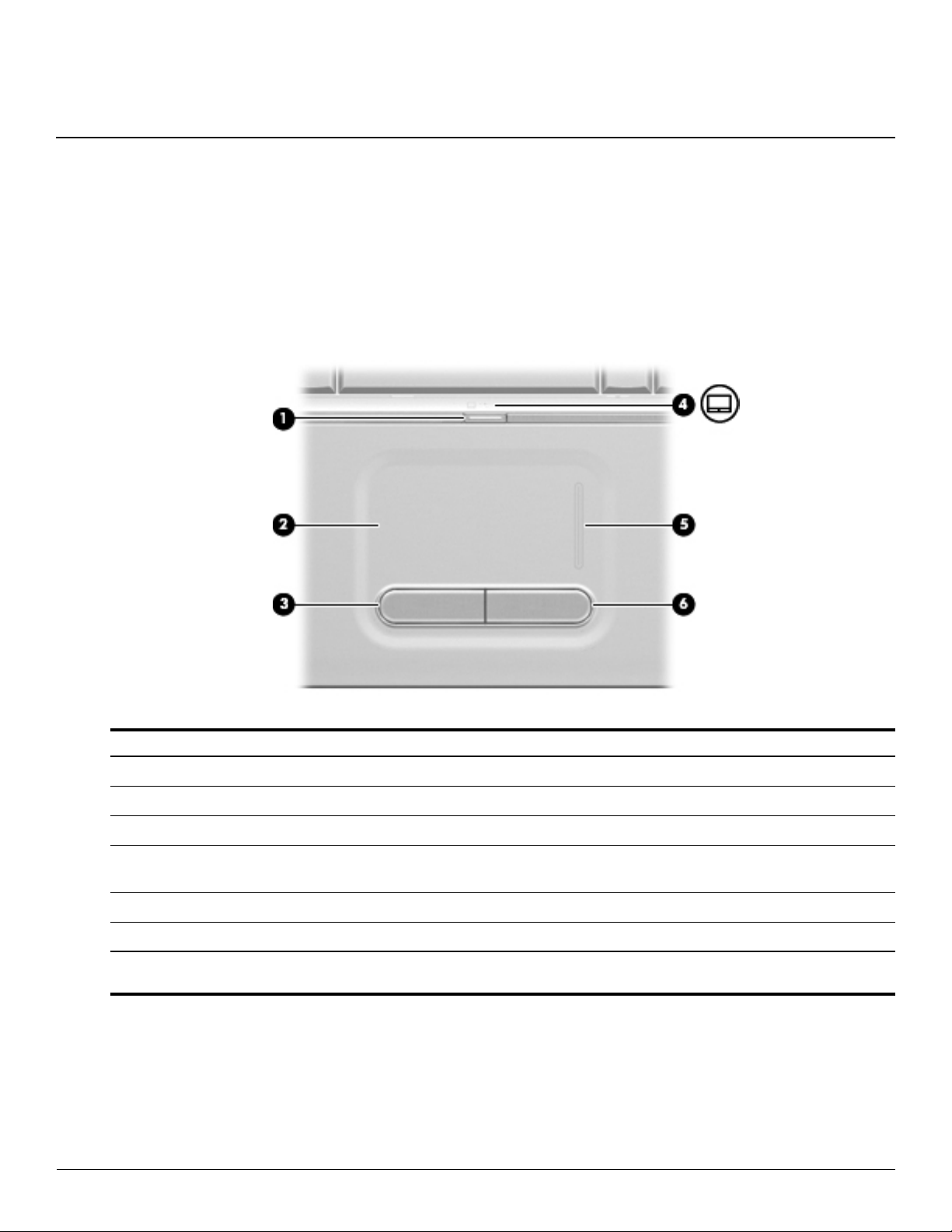
TouchPad
2
External component identification
Item Component Function
TouchPad on/off button Enables/disables the TouchPad.
1
TouchPad* Moves the pointer and selects or activates items on the screen.
2
Left TouchPad button* Functions like the left button on an external mouse.
3
TouchPad light ■ White: TouchPad is enabled.
4
■ Amber: TouchPad is disabled.
TouchPad scroll zone Scrolls up or down.
5
Right TouchPad button* Functions like the right button on an external mouse.
6
*This table describes factory settings. To view and change pointing device preferences, select Start > Control Panel >
Hardware and Sound > Mouse.
Maintenance and Service Guide 2–1
Page 14
External component identification
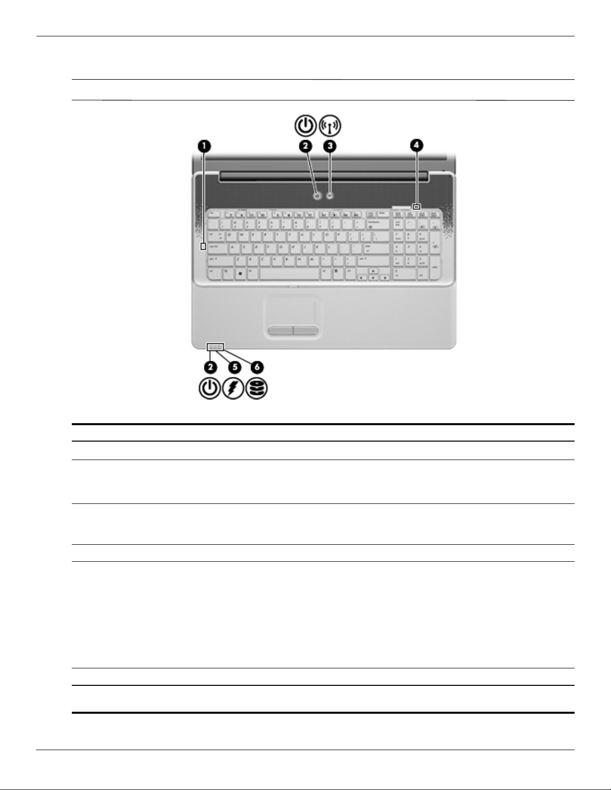
Lights
Your computer may look slightly different from the illustration in this section.
✎
Item Component Description
Caps lock light On: Caps lock is on.
1
2 Power lights (2)* ■ On: The computer is on.
■ Blinking: The computer is in the Sleep state.
■ Off: The computer is off or in Hibernation.
3 Wireless light ■ Blue: An integrated wireless device, such as a wireless local area
network (WLAN) device and/or a Bluetooth® device, is on.
■ Amber: All wireless devices are off.
4 Num lock light On: Keypad numeric function is enabled.
5 Battery light ■ On: A battery is charging.
■ Blinking: A battery that is the only available power source has
reached a low battery level. When the battery reaches a critical
battery level, the battery light begins blinking rapidly.
■ Off: If the computer is plugged into an external power source, the
light is turned off when all batteries in the computer are fully
charged. If the computer is not plugged into an external power
source, the light stays off until the battery reaches a low battery
level.
6 Drive light Blinking: The hard drive or optical drive is being accessed.
*The 2 power lights display the same information. The light on the power button is visible only when the computer is open. The
power light on the front of the computer is visible whether the computer is open or closed.
2–2 Maintenance and Service Guide
Page 15
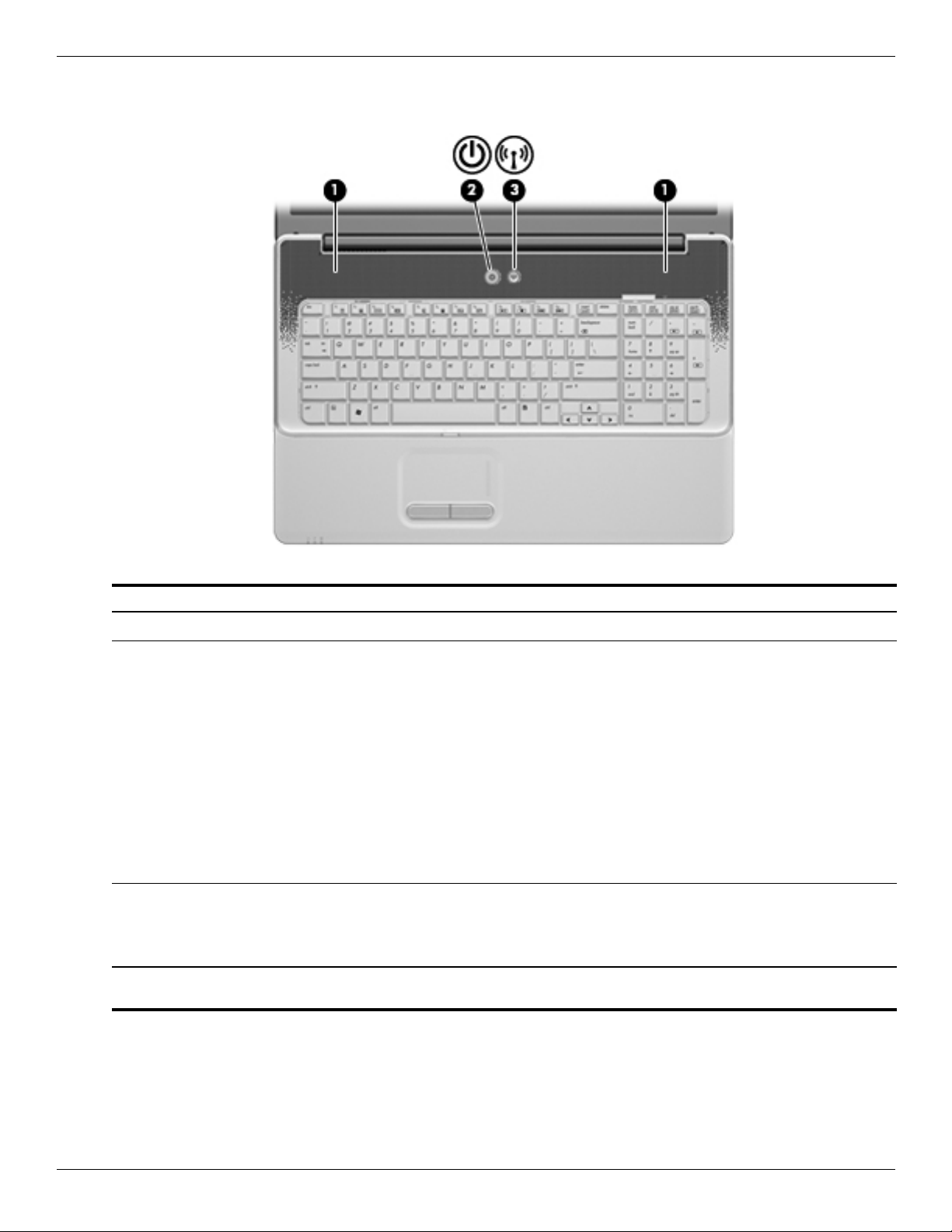
Buttons
External component identification
Item Component Description
Speakers (2) Produce sound.
1
Powe r button* ■ When the computer is off, press the button to turn on the
2
Wireless button Turns the wireless feature on or off but does not create a wireless
3
*This table describes factory settings. For information about changing factory settings, refer to the user guides located in Help
and Support.
computer.
■ When the computer is on, press the button briefly to initiate
Sleep.
■ When the computer is in the Sleep state, press the button
briefly to exit Sleep.
■ When the computer is in Hibernation, press the button briefly to
exit Hibernation.
If the computer has stopped responding and Windows®
shutdown procedures are ineffective, press and hold the power
button for at least 5 seconds to turn off the computer.
To learn more about your power settings, select Start > Control
Panel > System and Maintenance > Power Options.
connection.
To establish a wireless connection, a wireless network
✎
must already be set up.
Maintenance and Service Guide 2–3
Page 16
External component identification
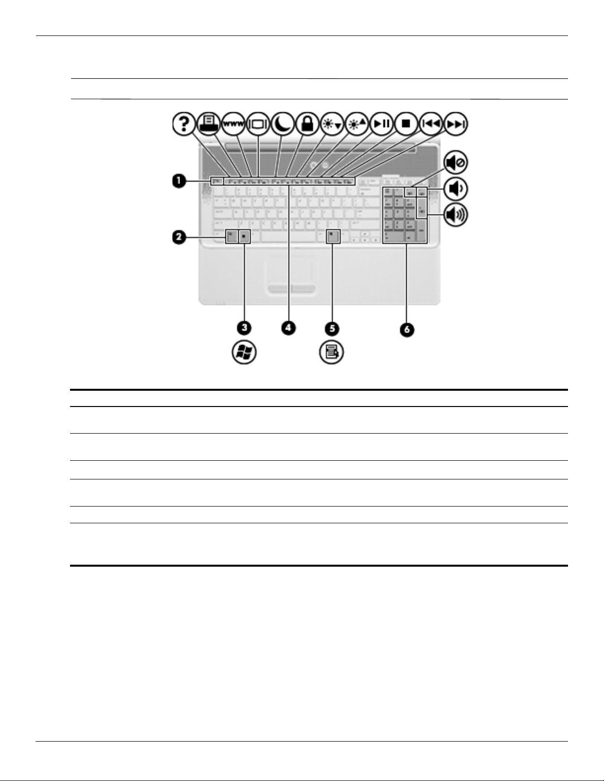
Keys
Your computer may look slightly different from the illustration in this section.
✎
Item Component Description
1 esc key Displays system information when pressed in combination with
fn key.
the
2 fn key Executes frequently used system functions when pressed in
combination with a function key or the
Windows logo key Displays the Windows Start menu.
3
esc key.
4 Function keys Execute frequently used system functions when pressed in
combination with the
fn key.
5 Windows applications key Displays a shortcut menu for items beneath the pointer.
6 Integrated numeric keypad and volume hotkeys ■ Can be used like the keys on an external numeric keypad.
■ Adjusts system volume when the asterisk (*), minus sign (-),
or plus sign (+) is pressed in combination with the
fn key.
2–4 Maintenance and Service Guide
Page 17
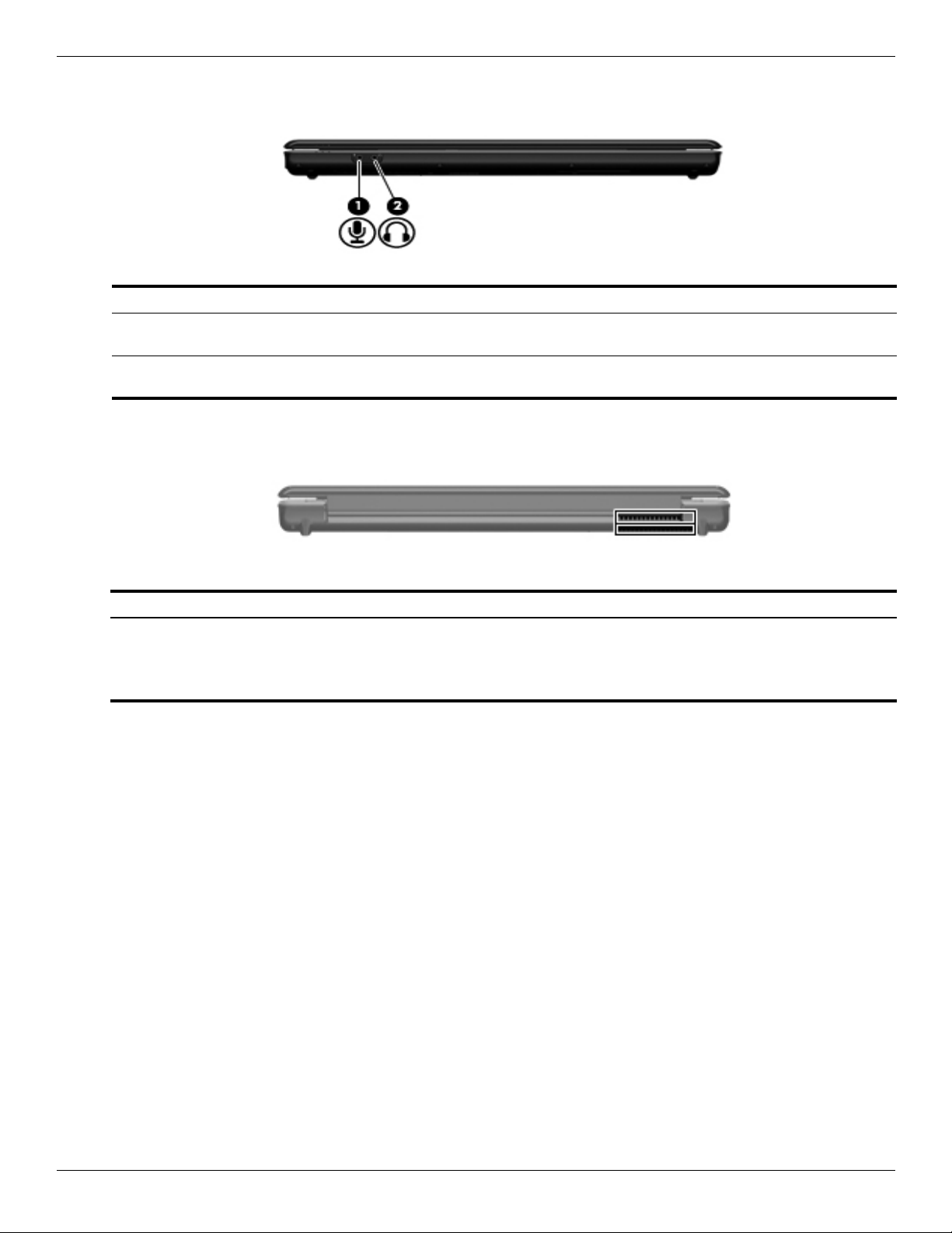
Front components
Item Component Description
1 Audio-in (microphone) jack Connects an optional computer headset microphone, stereo array
2 Audio-out (headphone) jack Produces sound when connected to optional powered stereo
Rear components
External component identification
microphone, or monaural microphone.
speakers, headphones, ear buds, a headset, or television audio.
Component Function
Vents (2) Enable airflow to cool internal components.
The computer fan starts up automatically to cool internal
✎
components and prevent overheating. It is normal for the
internal fan to cycle on and off during routine operation.
Maintenance and Service Guide 2–5
Page 18
External component identification
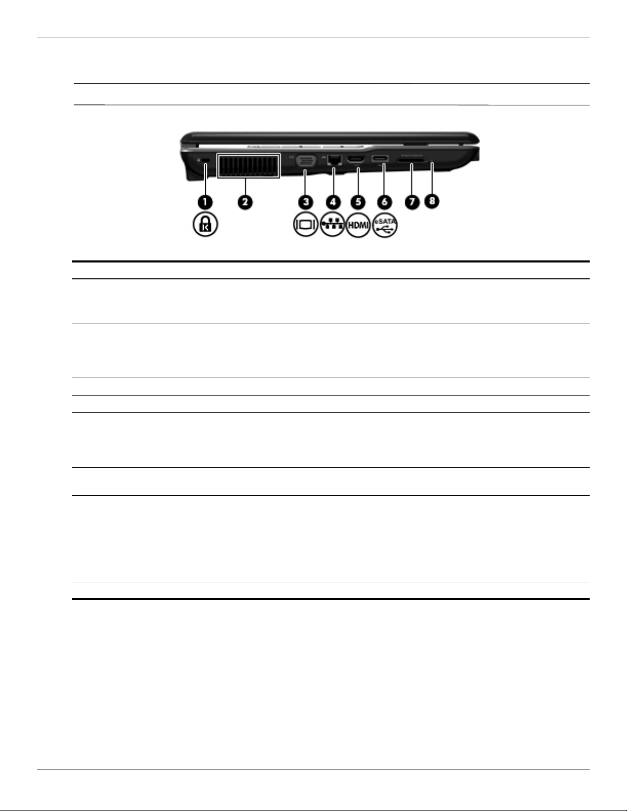
Left-side components
Your computer may look slightly different from the illustration in this section.
✎
Item Component Function
1 Security cable slot Attaches an optional security cable to the computer.
2 Vent Enables airflow to cool internal components.
The security cable is designed to act as a deterrent, but it may
✎
not prevent the computer from being mishandled or stolen.
The computer fan starts up automatically to cool internal
✎
components and prevent overheating. It is normal for the
internal fan to cycle on and off during routine operation.
3 External monitor port Connects an external VGA monitor or projector.
4 RJ-45 (network) jack Connects a network cable.
5 HDMI port (select models only) Connects an optional video or audio device, such as a high-definition
television, or any compatible digital or audio component.
Depending on your computer model, the computer may include
✎
an HDMI port or a USB port at this location.
eSATA/USB port Connects a high-performance eSATA component, such as an eSATA
6
Digital Media Slot (select models only) Supports the following digital card formats:
7
8 Digital Media Slot light (select models only) On: The Digital Media Slot is in use.
external hard drive, or connects an optional USB device.
■ Memory Stick (MS)
■ Memory Stick Pro (MSP)
■ MultiMediaCard (MMC)
■ Secure Digital (SD) Memory Card
■ xD-Picture Card (XD)
2–6 Maintenance and Service Guide
Page 19
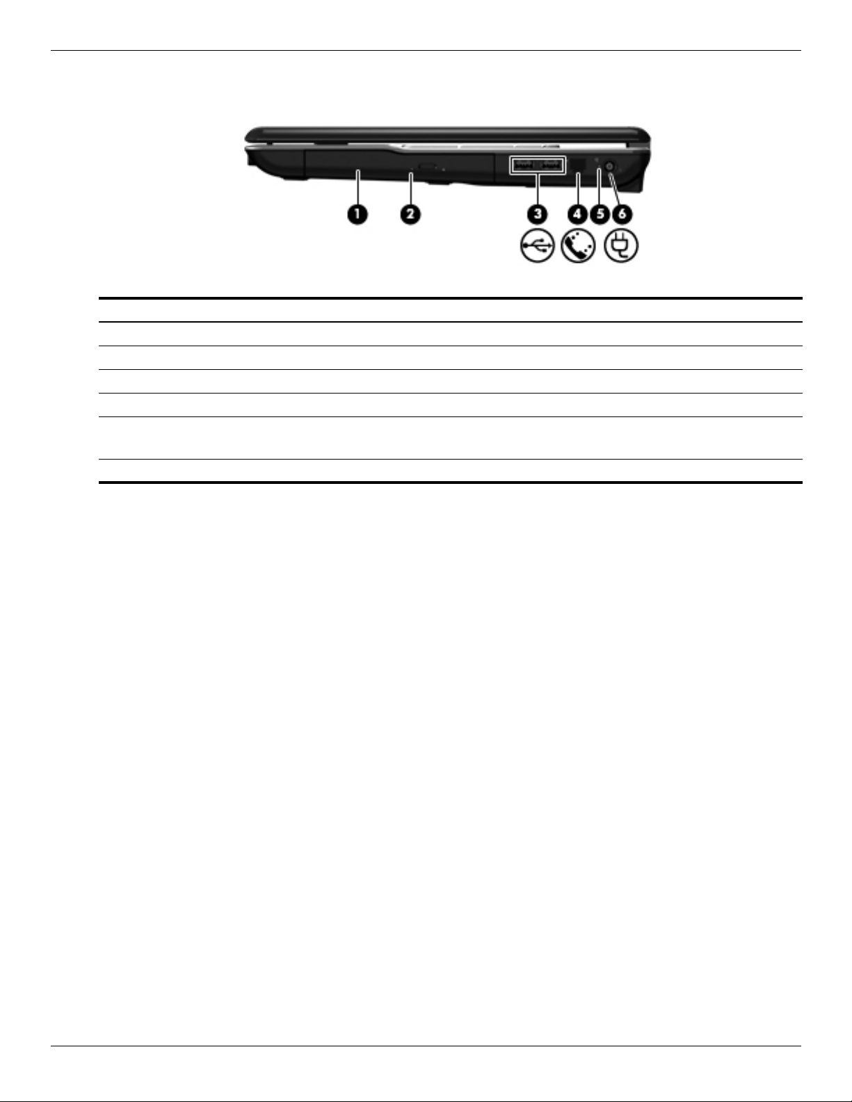
Right-side components
Item Component Function
1 Optical drive Reads optical discs and, on select models, also writes to optical discs.
2 Optical drive light Blinking: The optical drive is being accessed.
3 USB ports (2) Connect optional USB devices.
4 RJ-11 (modem) jack (select models only) Connects a modem cable.
5 AC adapter light ■ On: The computer is connected to external power.
External component identification
■ Off: The computer is not connected to external power.
6 Power connector Connects an AC adapter.
Maintenance and Service Guide 2–7
Page 20
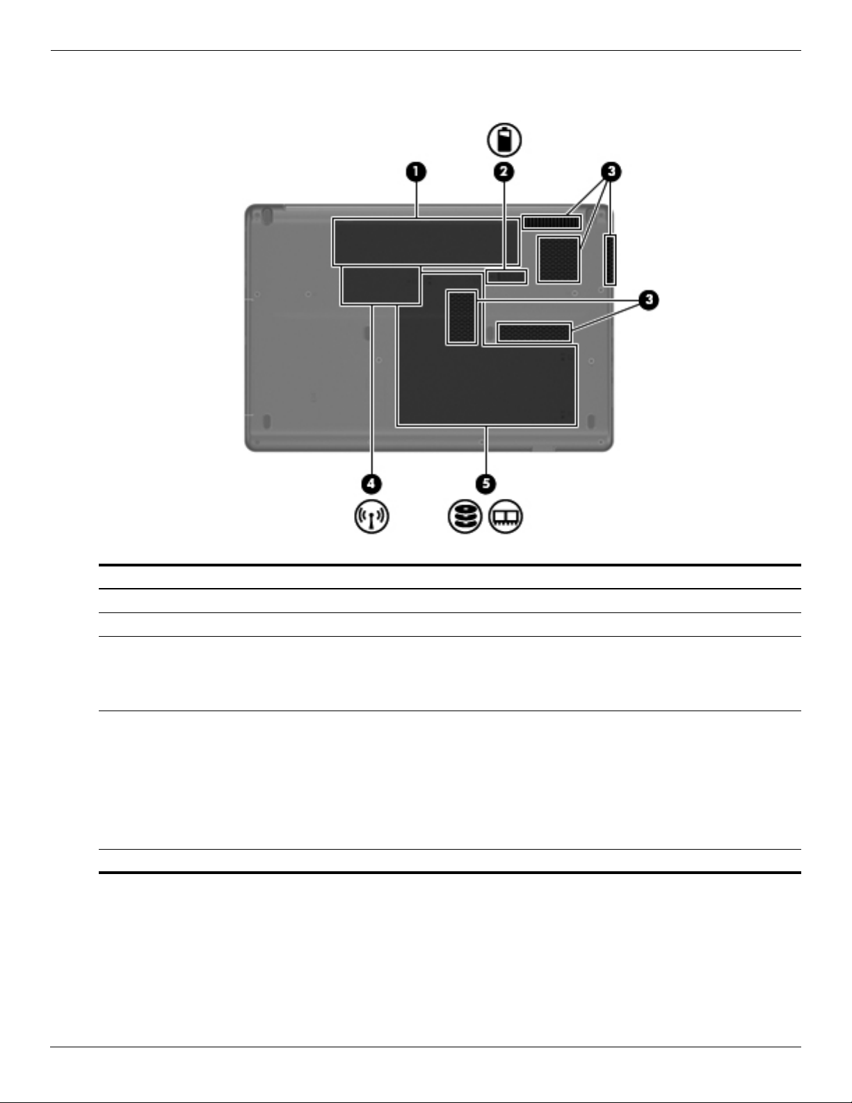
External component identification
Bottom components
Item Component Function
1 Battery bay Holds the battery.
2 Battery release latch Releases the battery from the battery bay.
3 Vents (5) Enable airflow to cool internal components.
The computer fan starts up automatically to cool internal
✎
components and prevent overheating. It is normal for the
internal fan to cycle on and off during routine operation.
4 Wireless module compartment Holds a wireless LAN module.
To prevent an unresponsive system, replace the wireless
Ä
module with only a wireless module authorized for use in
the computer by the governmental agency that regulates
wireless devices in your country or region. If you replace
the module and then receive a warning message, remove
the module to restore computer functionality, and then
contact technical support through Help and Support.
5 Hard drive bay Holds the hard drive and contains the memory module slots.
2–8 Maintenance and Service Guide
Page 21
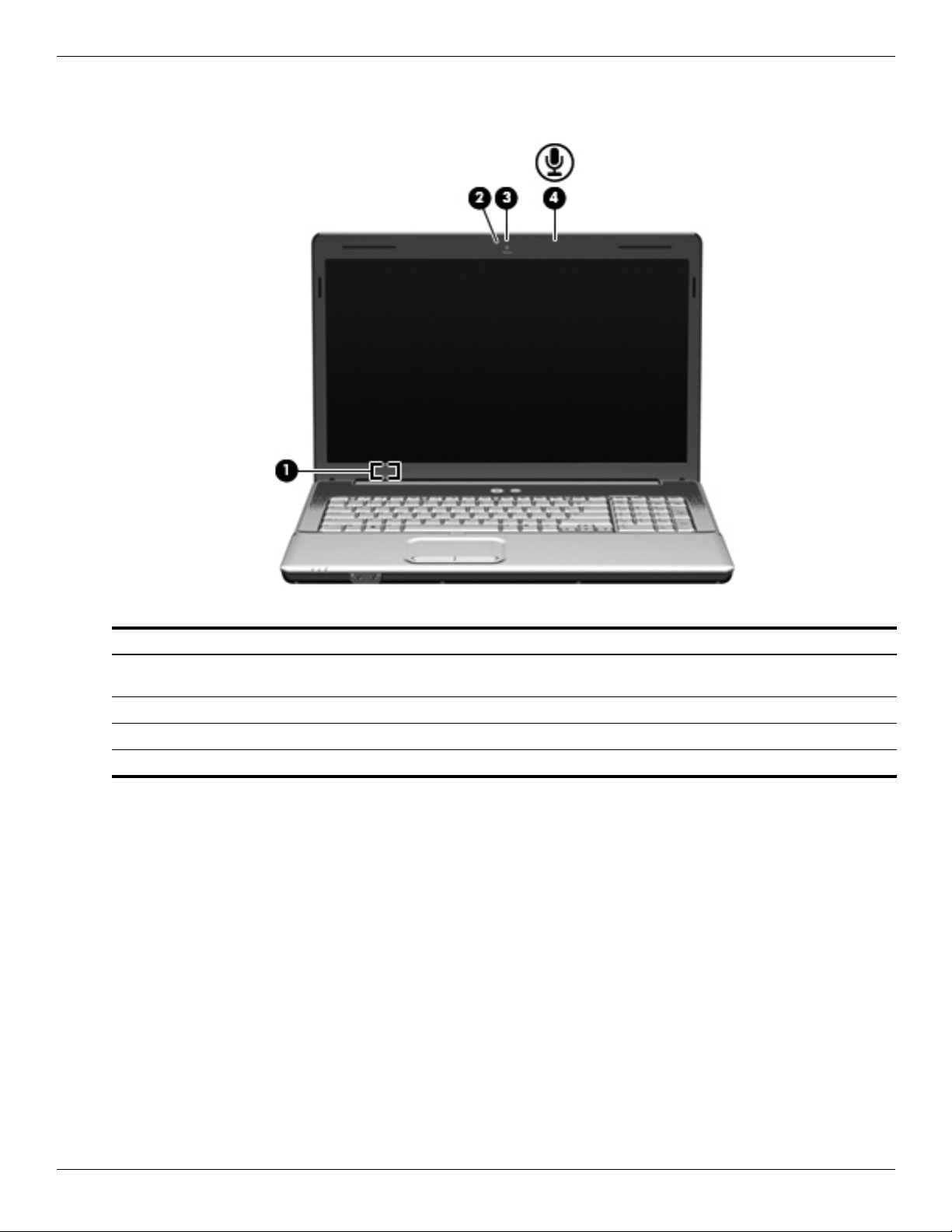
Display components
External component identification
Item Component Description
1 Internal display switch Turns off the display and initiates Sleep if the display is closed
while the power is on.
2 Webcam light (select models only) On: The webcam is in use.
3 Webcam (select models only) Records audio and video and captures still photographs.
4 Internal microphone Records sound.
Maintenance and Service Guide 2–9
Page 22
External component identification
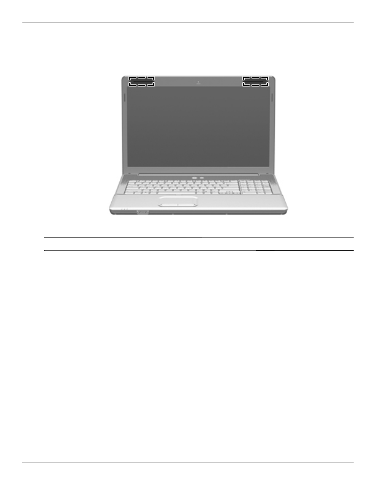
Wireless antennas
Your computer model has at least 2 antennas that send and receive signals from one or more wireless devices.
These antennas are not visible from the outside of the computer.
For optimal transmission, keep the areas immediately around the antennas free from obstructions.
✎
To see wireless regulatory notices, refer to the section of the Regulatory, Safety and Environmental Notices that
applies to your country or region. These notices are located in Help and Support.
2–10 Maintenance and Service Guide
Page 23
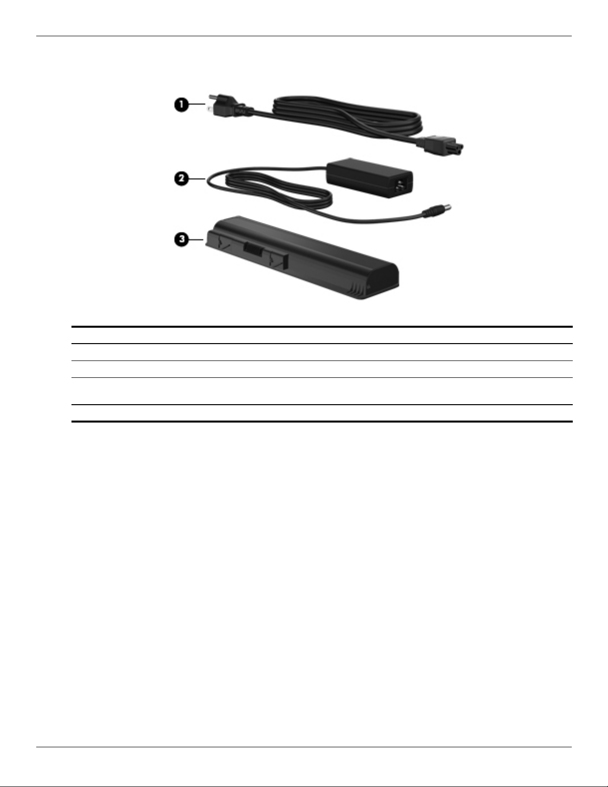
Additional hardware components
External component identification
Item Component Description
1 Power cord* Connects an AC adapter to an AC outlet.
2 AC adapter Converts AC power to DC power.
3 Battery* Powers the computer when the computer is not plugged into
external power.
*Batteries and power cords vary in appearance by region and country.
Maintenance and Service Guide 2–11
Page 24
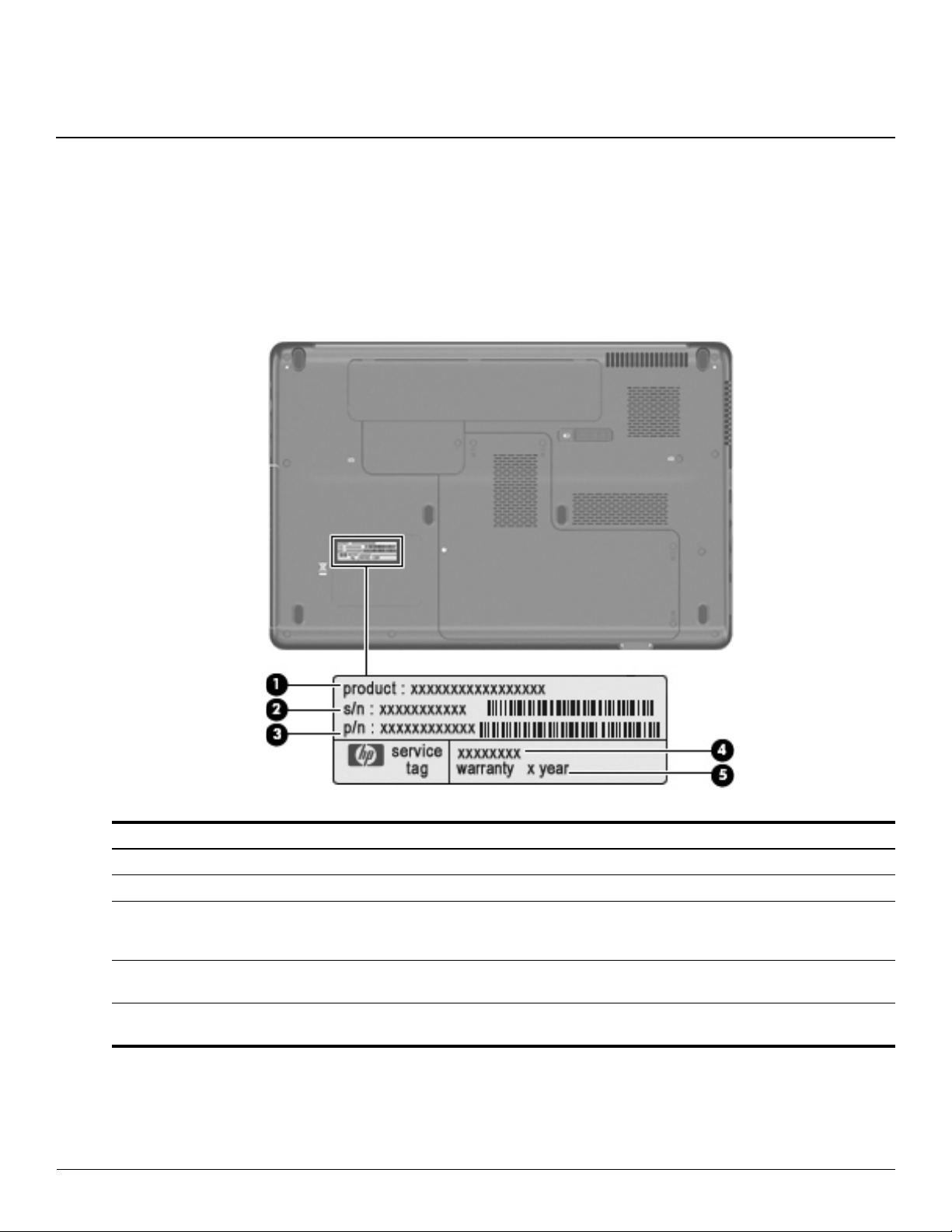
Service tag
When ordering parts or requesting information, provide the computer serial number and model number located on
the service tag.
3
Illustrated parts catalog
Component Description
1 Product name This is the product name affixed to the front of your computer.
2 Serial number (s/n) This is an alphanumeric identifier that is unique to each product.
3 Part number/ product number
(p/n)
4 Model description This is the alphanumeric identifier you use to locate documents, drivers, and
5 Warranty period This number describes the duration (in years) of the warranty period for this
Maintenance and Service Guide 3–1
This number provides specific information about the product’s hardware
components. The part number helps a service technician to determine what
components and parts are needed.
support for your computer.
computer.
Page 25
Illustrated parts catalog
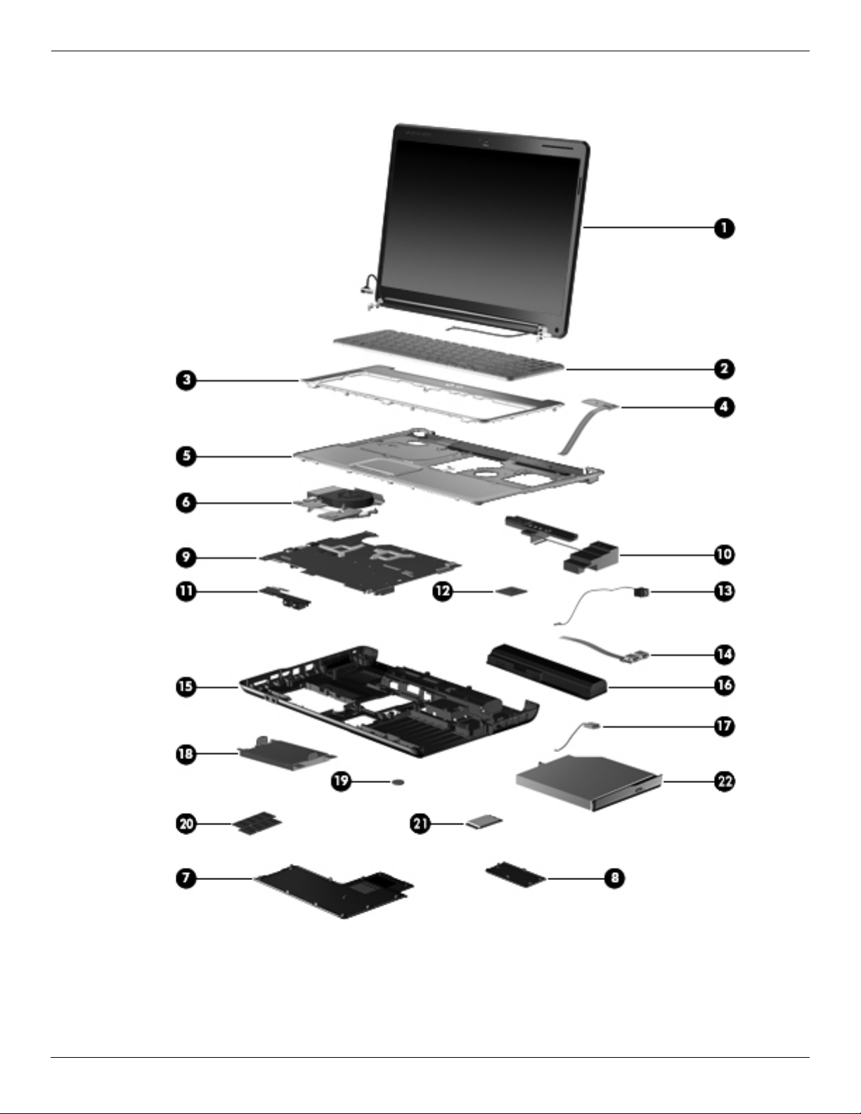
Computer major components
3–2 Maintenance and Service Guide
Page 26

Illustrated parts catalog
Item Description Spare Part Number
(1) 16-in High Definition (HD), light-emitting diode (LED) display assembly
For use in HP G61 computer models (includes webcam module and cable, 2 WLAN antenna
transceivers and cables, microphone and cable, and logo)
530981-001
For use in Presario G61 computer models (includes webcam module and cable, 2 WLAN
antenna transceivers and cables, microphone and cable, and logo)
15.6-in HD, light-emitting diode display assembly
For use in Presario CQ61 computer models (includes microphone and cable, and logo) 530979-001
For use in Presario CQ61 computer models (includes webcam module and cable, 2 WLAN
antenna transceivers and cables, microphone and cable, and logo)
For use in HP G61 computer models (includes microphone and cable, and logo) 530983-001
For use in HP G61 computer models (includes webcam module and cable, 2 WLAN antenna
transceivers and cables, microphone and cable, and logo)
(2) Keyboard (includes keyboard cable)
For use in Brazil 517865-201
For use in Canada 517865-121
For use in the Czech Republic 517865-221
For use in Belgium 517865-A41
For use in France 517865-051
For use in Germany 517865-041
For use in Greece 517865-151
For use in Hungry 517865-211
For use in Israel 517865-BB1
530977-001
530978-001
530982-001
For use in Italy 517865-061
For international use 517865-B31
For use in Latin America 517865-161
For us in Japan 517865-291
For used in Norway 517865-091
For use in Portugal 517865-131
For use in Russia 517865-251
For use in Saudi Arabia 517865-171
For use in South Korea 517865-AD1
For use in Spain 517865-071
For use in Switzerland 517865-BG1
For use in Thailand 517865-281
For use in Turkey 517865-141
For use in Taiwan 517865-AB1
For use in the United Kingdom 517865-031
For use in the United States 517865-001
(3) Switch cover 531207-001
(Continued)
Maintenance and Service Guide 3–3
Page 27

Illustrated parts catalog
Item Description Spare Part Number
(4) Power button board (includes power button board cable) 531215-001
(5) Top cover (includes TouchPad board) 531206-001
(6) Fan/heat sink assembly for use with UMA systems (includes replacement thermal material) 531210-001
Fan/heat sink assembly for use with discrete systems (includes replacement thermal
material)
Plastics Kit (see “Plastics Kit” on page 12 for contents) 531517-001
(7) Hard drive cover
(8) Wireless module compartment cover
(9) System board
GM45 UMA system board for use with select UMA computer models (includes built-in
modem, Digital Media Slot, HDMI port, and replacement thermal material)
GM45 UMA system board for use with select UMA computer models (includes built-in
modem, Digital Media Slot, and replacement thermal material)
GL40 UMA system board for use only with select UMA computer models (includes built-in
modem, Digital Media Slot, and replacement thermal material)
GL40 UMA system board for use with select UMA computer models (includes built-in
modem, Digital Media Slot, HDMI port, and replacement thermal material)
GL40 UMA system board for use with select UMA computer models (includes built-in
modem, Digital Media Slot, HDMI port and replacement thermal material)
PM45 Discrete system board for use with select Discrete computer models (includes built-in
modem, Digital Media Slot, HDMI port, and replacement thermal material)
PM45 Discrete system board for use with select Discrete computer models (includes built-in
modem, Digital Media Slot, and replacement thermal material)
(10) Speakers (include left and right speakers and cables)
531220-001
517839-001
517832-001
517836-001
517835-001
570246-001
517837-001
517838-001
For use in India only 572082-001
For use in all countries and regions except India 531209-001
(11) Audio board (includes audio board cable) 531208-001
(12) Processor (includes replacement thermal material)
Intel Core2 Duo processors (3-MB L2 cache, 1066-MHz FSB)
■ P8700 2.53-GHz processor 507960-001
■ P7550 2.26-GHz processor 573076-001
■ P7450 2.13-GHz processor 507965-001
■ T6600 2.20-GHz processor 513593-001
■ T6500 2.10 GHz processor 572928-001
■ T6400 2.06-GHz processor 513592-001
Intel Pentium Dual-Core processors (1-MB L2 cache, 667-MHz FSB)
■ T3400 2.16-GHz processor 509549-001
Intel Pentium Dual-Core processors (1-MB L2 cache, 800-MHz FSB)
■ T4200 2.06-GHz processor 513599-001
(Continued)
3–4 Maintenance and Service Guide
Page 28

Illustrated parts catalog
Item Description Spare Part Number
Intel Celeron processors (1-MB L2 cache, 667-MHz FSB)
■ 900 2.20-GHz processor 534419-001
■ 585 2.16-GHz processor 519898-001
■ T1700 1.83-GHz processor 534084-001
■ T1600 1.66-GHz processor 532324-001
(13) Power connector cable 533465-001
(14) USB board (does not include USB board cable) 531866-001
USB board cable (included in “Cable Kit” on page 13)
(15) Base enclosure (with card reader, includes rubber feet) 531205-001
Rubber Kit (not illustrated, includes 6 rubber feet) 531213-001
(16) Battery, 6-cell, 2.20-Ah, 47-Wh 531775-001
(17) Bluetooth® module (does not include Bluetooth cable) 483113-001
Bluetooth cable (not illustrated) (included in “Cable Kit” on page 13)
(18) Hard drive (includes hard drive bracket and connector)
500-GB, 5400-rpm 517848-001
320-GB, 5400-rpm 517847-001
250-GB, 5400-rpm 517846-001
160-GB, 5400-rpm 517845-001
Hard Drive Hardware Kit (not illustrated, includes connector, bracket, and screws) 531204-001
(19) RTC battery 449729-001
(20) Memory modules
PC2-6400, 800-MHz, DDR2
2-GB 517844-001
1-GB 517843-001
(21) Wireless (WLAN) module
Atheros AR9280 802.11 a/g/n WLAN module:
■ For use in Canada, the Cayman Islands, Guam, Puerto Rico, the U.S. Virgin Islands, and
the United States
482260-001
(Continued)
Maintenance and Service Guide 3–5
Page 29

Illustrated parts catalog
Item Description Spare Part Number
■ For use in Afghanistan, Albania, Algeria, Andorra, Angola, Antigua and Barbuda,
Argentina, Armenia, Aruba, Australia, Austria, Azerbaijan, the Bahamas, Bahrain,
Bangladesh, Barbados, Belarus, Belgium, Belize, Benin, Bermuda, Bhutan, Bolivia,
Bosnia and Herzegovina, Botswana, Brazil, the British Virgin Islands, Brunei, Bulgaria,
Burkina Faso, Burundi, Cameroon, Cape Verde, the Central African Republic, Chad,
Chile, Colombia, Comoros, the Congo, Costa Rica, Croatia, Cyprus, the Czech Republic,
Denmark, Djibouti, Dominica, the Dominican Republic, East Timor, Ecuador, Egypt, El
Salvador, Equitorial Guinea, Eritrea, Estonia, Ethiopia, Fiji, Finland, France, French
Guiana, Gabon, Gambia, Georgia, Germany, Ghana, Gibraltar, Greece, Grenada,
Guadeloupe, Guatemala, Guinea, Guinea-Bissau, Guyana, Haiti, Honduras, Hong Kong,
Hungary, Iceland, India, Ireland, Israel, Italy, the Ivory Coast, Jamaica, Jordan,
Kazakhstan, Kenya, Kiribati, Kyrgyzstan, Laos, Latvia, Lebanon, Lesotho, Liberia,
Liechtenstein, Lithuania, Luxembourg, Macedonia, Madagascar, Malawi, Malaysia, the
Maldives, Mali, Malta, the Marshall Islands, Martinique, Mauritania, Mauritius, Mexico,
Micronesia, Monaco, Mongolia, Montenegro, Morocco, Mozambique, Namibia, Nauru,
Nepal, the Nether Antilles, the Netherlands, New Zealand, Nicaragua, Niger, Nigeria,
Norway, Oman, Pakistan, Palau, Panama, Papua New Guinea, Paraguay, the People's
Republic of China, Peru, the Philippines, Poland, Portugal, the Republic of Moldova,
Romania, Russia, Rwanda, Samoa, San Marino, Sao Tome and Principe, Saudi Arabia,
Senegal, Serbia and Montenegro, the Seychelles, Sierra Leone, Singapore, Slovakia,
Slovenia, the Solomon Islands, Somalia, South Africa, South Korea, Spain, Sri Lanka, St.
Kitts and Nevis, St. Lucia, St. Vincent and the Grenadines, Suriname, Swaziland,
Sweden, Switzerland, Taiwan, Tajikistan, Tanzania, Togo, Tonga, Trinidad and Tobago,
Tunisia, Turkey, Turkmenistan, Tuvalu, Uganda, Ukraine, the United Arab Emirates, the
United Kingdom, Uruguay, Uzbekistan, Vanuatu, Venezuela, Vietnam, Yemen, Zaire,
Zambia, and Zimbabwe
Atheros AR2425 802.11b/g WLAN module:
■ For use in Canada, the Cayman Islands, Guam, Puerto Rico, the U.S. Virgin Islands, and
the United States
482260-002
459339-003
■ For use in Afghanistan, Albania, Algeria, Andorra, Angola, Antigua and Barbuda,
Argentina, Armenia, Aruba, Australia, Austria, Azerbaijan, the Bahamas, Bahrain,
Bangladesh, Barbados, Belarus, Belgium, Belize, Benin, Bermuda, Bhutan, Bolivia,
Bosnia and Herzegovina, Botswana, Brazil, the British Virgin Islands, Brunei, Bulgaria,
Burkina Faso, Burundi, Cambodia, Cameroon, Cape Verde, the Central African Republic,
Chad, Chile, Colombia, Comoros, Congo, Costa Rica, Croatia, Cyprus, the Czech
Republic, Denmark, Djibouti, Dominica, the Dominican Republic, East Timor, Ecuador,
Egypt, El Salvador, Equitorial Guinea, Eritrea, Estonia, Ethiopia, Fiji, Finland, France,
French Guiana, Gabon, Gambia, Georgia, Germany, Ghana, Gibraltar, Greece, Grenada,
Guadeloupe, Guatemala, Guinea, Guinea-Bissau, Guyana, Haiti, Honduras, Hong Kong,
Hungary, Iceland, India, Indonesia, Ireland, Israel, Italy, the Ivory Coast, Jamaica, Japan,
Jordan, Kazakhstan, Kenya, Kiribati, Kuwait, Kyrgyzstan, Laos, Latvia, Lebanon, Lesotho,
Liberia, Liechtenstein, Lithuania, Luxembourg, Macedonia, Madagascar, Malawi,
Malaysia, the Maldives, Mali, Malta, the Marshall Islands, Martinique, Mauritania,
Mauritius, Mexico, Micronesia, Monaco, Mongolia, Montenegro, Morocco, Mozambique,
Namibia, Nauru, Nepal, the Nether Antilles, the Netherlands, New Zealand, Nicaragua,
Niger, Nigeria, Norway, Oman, Pakistan, Palau, Panama, Papua New Guinea, Paraguay,
the People's Republic of China, Peru, the Philippines, Poland, Portugal, Qatar, the
Republic of Moldova, Romania, Russia, Rwanda, Samoa, San Marino, Sao Tome and
Principe, Saudi Arabia, Senegal, Serbia and Montenegro, Seychelles, Sierra Leone,
Singapore, Slovakia, Slovenia, the Solomon Islands, Somalia, South Africa, South Korea,
Spain, Sri Lanka, St. Kitts and Nevis, St. Lucia, St. Vincent and the Grenadines,
Suriname, Swaziland, Sweden, Switzerland, Syria, Taiwan, Tajikistan, Tanzania,
Thailand, Togo, Tonga, Trinidad and Tobago, Tu n i si a , Tu rkey, Tu rk m e n is t a n , Tuva l u ,
Uganda, Ukraine, the United Arab Emirates, the United Kingdom, Uruguay, Uzbekistan,
Vanuatu, Venezuela, Vietnam, Yemen, Zaire, Zambia, and Zimbabwe
Atheros 802.11 b/g/n
459339-004
■ For use in Canada, the Cayman Islands, Guam, Puerto Rico, the U.S. Virgin Islands, and
the United States
518436-001
(Continued)
3–6 Maintenance and Service Guide
Page 30

Illustrated parts catalog
Item Description Spare Part Number
■ For use in Afghanistan, Albania, Algeria, Andorra, Angola, Antigua and Barbuda,
Argentina, Armenia, Aruba, Australia, Austria, Azerbaijan, the Bahamas, Bahrain,
Bangladesh, Barbados, Belarus, Belgium, Belize, Benin, Bermuda, Bhutan, Bolivia,
Bosnia and Herzegovina, Botswana, Brazil, the British Virgin Islands, Brunei, Bulgaria,
Burkina Faso, Burundi, Cambodia, Cameroon, Cape Verde, the Central African Republic,
Chad, Chile, Colombia, Comoros, Congo, Costa Rica, Croatia, Cyprus, the Czech
Republic, Denmark, Djibouti, Dominica, the Dominican Republic, East Timor, Ecuador,
Egypt, El Salvador, Equitorial Guinea, Eritrea, Estonia, Ethiopia, Fiji, Finland, France,
French Guiana, Gabon, Gambia, Georgia, Germany, Ghana, Gibraltar, Greece, Grenada,
Guadeloupe, Guatemala, Guinea, Guinea-Bissau, Guyana, Haiti, Honduras, Hong Kong,
Hungary, Iceland, India, Indonesia, Ireland, Israel, Italy, the Ivory Coast, Jamaica, Japan,
Jordan, Kazakhstan, Kenya, Kiribati, Kuwait, Kyrgyzstan, Laos, Latvia, Lebanon, Lesotho,
Liberia, Liechtenstein, Lithuania, Luxembourg, Macedonia, Madagascar, Malawi,
Malaysia, the Maldives, Mali, Malta, the Marshall Islands, Martinique, Mauritania,
Mauritius, Mexico, Micronesia, Monaco, Mongolia, Montenegro, Morocco, Mozambique,
Namibia, Nauru, Nepal, the Nether Antilles, the Netherlands, New Zealand, Nicaragua,
Niger, Nigeria, Norway, Oman, Pakistan, Palau, Panama, Papua New Guinea, Paraguay,
the People's Republic of China, Peru, the Philippines, Poland, Portugal, Qatar, the
Republic of Moldova, Romania, Russia, Rwanda, Samoa, San Marino, Sao Tome and
Principe, Saudi Arabia, Senegal, Serbia and Montenegro, Seychelles, Sierra Leone,
Singapore, Slovakia, Slovenia, the Solomon Islands, Somalia, South Africa, South Korea,
Spain, Sri Lanka, St. Kitts and Nevis, St. Lucia, St. Vincent and the Grenadines,
Suriname, Swaziland, Sweden, Switzerland, Syria, Taiwan, Tajikistan, Tanzania,
Thailand, Togo, Tonga, Trinidad and Tobago, Tu n i si a , Tu rkey, Tu rk m e n is t a n , Tuva l u ,
Uganda, Ukraine, the United Arab Emirates, the United Kingdom, Uruguay, Uzbekistan,
Vanuatu, Venezuela, Vietnam, Yemen, Zaire, Zambia, and Zimbabwe
Atheros 802.11 a/b/g/n WLAN module
■ For use in Canada, the Cayman Islands, Guam, Puerto Rico, the U.S. Virgin Islands, and
the United States
518436-002
518437-001
■ For use in Afghanistan, Albania, Algeria, Andorra, Angola, Antigua and Barbuda,
Argentina, Armenia, Aruba, Australia, Austria, Azerbaijan, the Bahamas, Bahrain,
Bangladesh, Barbados, Belarus, Belgium, Belize, Benin, Bermuda, Bhutan, Bolivia,
Bosnia and Herzegovina, Botswana, Brazil, the British Virgin Islands, Brunei, Bulgaria,
Burkina Faso, Burundi, Cambodia, Cameroon, Cape Verde, the Central African Republic,
Chad, Chile, Colombia, Comoros, Congo, Costa Rica, Croatia, Cyprus, the Czech
Republic, Denmark, Djibouti, Dominica, the Dominican Republic, East Timor, Ecuador,
Egypt, El Salvador, Equitorial Guinea, Eritrea, Estonia, Ethiopia, Fiji, Finland, France,
French Guiana, Gabon, Gambia, Georgia, Germany, Ghana, Gibraltar, Greece, Grenada,
Guadeloupe, Guatemala, Guinea, Guinea-Bissau, Guyana, Haiti, Honduras, Hong Kong,
Hungary, Iceland, India, Indonesia, Ireland, Israel, Italy, the Ivory Coast, Jamaica, Japan,
Jordan, Kazakhstan, Kenya, Kiribati, Kuwait, Kyrgyzstan, Laos, Latvia, Lebanon, Lesotho,
Liberia, Liechtenstein, Lithuania, Luxembourg, Macedonia, Madagascar, Malawi,
Malaysia, the Maldives, Mali, Malta, the Marshall Islands, Martinique, Mauritania,
Mauritius, Mexico, Micronesia, Monaco, Mongolia, Montenegro, Morocco, Mozambique,
Namibia, Nauru, Nepal, the Nether Antilles, the Netherlands, New Zealand, Nicaragua,
Niger, Nigeria, Norway, Oman, Pakistan, Palau, Panama, Papua New Guinea, Paraguay,
the People's Republic of China, Peru, the Philippines, Poland, Portugal, Qatar, the
Republic of Moldova, Romania, Russia, Rwanda, Samoa, San Marino, Sao Tome and
Principe, Saudi Arabia, Senegal, Serbia and Montenegro, Seychelles, Sierra Leone,
Singapore, Slovakia, Slovenia, the Solomon Islands, Somalia, South Africa, South Korea,
Spain, Sri Lanka, St. Kitts and Nevis, St. Lucia, St. Vincent and the Grenadines,
Suriname, Swaziland, Sweden, Switzerland, Syria, Taiwan, Tajikistan, Tanzania,
Thailand, Togo, Tonga, Trinidad and Tobago, Tu n i si a , Tu rkey, Tu rk m e n is t a n , Tuva l u ,
Uganda, Ukraine, the United Arab Emirates, the United Kingdom, Uruguay, Uzbekistan,
Vanuatu, Venezuela, Vietnam, Yemen, Zaire, Zambia, and Zimbabwe
518437-002
(Continued)
Maintenance and Service Guide 3–7
Page 31

Illustrated parts catalog
Item Description Spare Part Number
Broadcom BCM4312 802.11b/g WLAN module:
■ For use in Canada, the Cayman Islands, Guam, Puerto Rico, the U.S. Virgin Islands, and
the United States
459263-001
■ For use in Afghanistan, Albania, Algeria, Andorra, Angola, Antigua and Barbuda,
Argentina, Armenia, Aruba, Australia, Austria, Azerbaijan, the Bahamas, Bahrain,
Bangladesh, Barbados, Belarus, Belgium, Belize, Benin, Bermuda, Bhutan, Bolivia,
Bosnia and Herzegovina, Botswana, Brazil, the British Virgin Islands, Brunei, Bulgaria,
Burkina Faso, Burundi, Cameroon, Cape Verde, the Central African Republic, Chad,
Chile, Colombia, Comoros, the Congo, Costa Rica, Croatia, Cyprus, the Czech Republic,
Denmark, Djibouti, Dominica, the Dominican Republic, East Timor, Ecuador, Egypt, El
Salvador, Equitorial Guinea, Eritrea, Estonia, Ethiopia, Fiji, Finland, France, French
Guiana, Gabon, Gambia, Georgia, Germany, Ghana, Gibraltar, Greece, Grenada,
Guadeloupe, Guatemala, Guinea, Guinea-Bissau, Guyana, Haiti, Honduras, Hong Kong,
Hungary, Iceland, India, Ireland, Israel, Italy, the Ivory Coast, Jamaica, Jordan,
Kazakhstan, Kenya, Kiribati, Kyrgyzstan, Laos, Latvia, Lebanon, Lesotho, Liberia,
Liechtenstein, Lithuania, Luxembourg, Macedonia, Madagascar, Malawi, Malaysia, the
Maldives, Mali, Malta, the Marshall Islands, Martinique, Mauritania, Mauritius, Mexico,
Micronesia, Monaco, Mongolia, Montenegro, Morocco, Mozambique, Namibia, Nauru,
Nepal, the Nether Antilles, the Netherlands, New Zealand, Nicaragua, Niger, Nigeria,
Norway, Oman, Pakistan, Palau, Panama, Papua New Guinea, Paraguay, the People's
Republic of China, Peru, the Philippines, Poland, Portugal, the Republic of Moldova,
Romania, Russia, Rwanda, Samoa, San Marino, Sao Tome and Principe, Saudi Arabia,
Senegal, Serbia and Montenegro, the Seychelles, Sierra Leone, Singapore, Slovakia,
Slovenia, the Solomon Islands, Somalia, South Africa, South Korea, Spain, Sri Lanka, St.
Kitts and Nevis, St. Lucia, St. Vincent and the Grenadines, Suriname, Swaziland,
Sweden, Switzerland, Taiwan, Tajikistan, Tanzania, Togo, Tonga, Trinidad and Tobago,
Tunisia, Turkey, Turkmenistan, Tuvalu, Uganda, Ukraine, the United Arab Emirates, the
United Kingdom, Uruguay, Uzbekistan, Vanuatu, Venezuela, Vietnam, Yemen, Zaire,
Zambia, and Zimbabwe
Intel Wi-Fi 5100 802.11 a/b/g for use only with Presario G61 computer models
459263-002
■ For use in Russia, Ukraine, and Pakistan 482957-001
(Continued)
3–8 Maintenance and Service Guide
Page 32

Illustrated parts catalog
Item Description Spare Part Number
■ Intel Wi-Fi 5100 802.11 a/b/g
■ For use in Afghanistan, Albania, Algeria, Andorra, Angola, Antigua and Barbuda,
Argentina, Armenia, Aruba, Australia, Austria, Azerbaijan, the Bahamas, Bahrain,
Bangladesh, Barbados, Belarus, Belgium, Belize, Benin, Bermuda, Bhutan, Bolivia,
Bosnia and Herzegovina, Botswana, Brazil, the British Virgin Islands, Brunei, Bulgaria,
Burkina Faso, Burundi, Cameroon, Cape Verde, the Central African Republic, Chad,
Chile, Colombia, Comoros, the Congo, Costa Rica, Croatia, Cyprus, the Czech Republic,
Denmark, Djibouti, Dominica, the Dominican Republic, East Timor, Ecuador, Egypt, El
Salvador, Equitorial Guinea, Eritrea, Estonia, Ethiopia, Fiji, Finland, France, French
Guiana, Gabon, Gambia, Georgia, Germany, Ghana, Gibraltar, Greece, Grenada,
Guadeloupe, Guatemala, Guinea, Guinea-Bissau, Guyana, Haiti, Honduras, Hong Kong,
Hungary, Iceland, India, Ireland, Israel, Italy, the Ivory Coast, Jamaica, Jordan,
Kazakhstan, Kenya, Kiribati, Kyrgyzstan, Laos, Latvia, Lebanon, Lesotho, Liberia,
Liechtenstein, Lithuania, Luxembourg, Macedonia, Madagascar, Malawi, Malaysia, the
Maldives, Mali, Malta, the Marshall Islands, Martinique, Mauritania, Mauritius, Mexico,
Micronesia, Monaco, Mongolia, Montenegro, Morocco, Mozambique, Namibia, Nauru,
Nepal, the Nether Antilles, the Netherlands, New Zealand, Nicaragua, Niger, Nigeria,
Norway, Oman, Pakistan, Palau, Panama, Papua New Guinea, Paraguay, the People's
Republic of China, Peru, the Philippines, Poland, Portugal, the Republic of Moldova,
Romania, Russia, Rwanda, Samoa, San Marino, Sao Tome and Principe, Saudi Arabia,
Senegal, Serbia and Montenegro, the Seychelles, Sierra Leone, Singapore, Slovakia,
Slovenia, the Solomon Islands, Somalia, South Africa, South Korea, Spain, Sri Lanka, St.
Kitts and Nevis, St. Lucia, St. Vincent and the Grenadines, Suriname, Swaziland,
Sweden, Switzerland, Taiwan, Tajikistan, Tanzania, Togo, Tonga, Trinidad and Tobago,
Tunisia, Turkey, Turkmenistan, Tuvalu, Uganda, Ukraine, the United Arab Emirates, the
United Kingdom, Uruguay, Uzbekistan, Vanuatu, Venezuela, Vietnam, Yemen, Zaire,
Zambia, and Zimbabwe
(22) Optical drive (includes optical drive bezel and bracket)
480985-001
DVD±RW and CD-RW SuperMulti Double-Layer Combo Drive with LightScribe 517850-001
Blu-ray ROM with LightScribe DVD±R/RW SuperMulti Double-Layer Drive 517852-001
Maintenance and Service Guide 3–9
Page 33

Illustrated parts catalog
Display assembly components
3–10 Maintenance and Service Guide
Page 34

Illustrated parts catalog
Item Description Spare Part Number
(1) Display bezel
For use only with 16-in HP G61 display (includes microphone and webcam) 530478-001
For use only with 15.6-in HP G61 display (includes microphone and webcam) 530992-001
For use only with 15.6-in HP G61 display (includes microphone) 534992-001
For use with 16-in Presario CQ-61 display (includes microphone and webcam) 534994-001
For use with 15.6-in Presario CQ-61 display (includes microphone and webcam) 534993-001
For use with 15.6-in Presario CQ-61 display (includes microphone) 534995-001
(2) Webcam module (webcam module cable included in Display Panel Cable Kit, 534077-001) 531202-001
(3) High Definition display panel (includes display panel and backlight cables)
For use only with 16-in display 531216-001
For use only with 15.6-in display 517842-001
(4) Display panel bracket (includes left and right brackets)
For use with 16-in display panels 530996-001
For use with 15.6-in display panels 530995-001
Display Panel Cable Kit with webcam cable (not illustrated) 534077-001
(5) Display Hinge Kit (includes left and right display hinges) 530993-001
(6) Wireless Antenna Kit (includes wireless antenna transceivers and cable)
(7) Microphone and caps lock cable (includes receiver and cable) 531203-001
(8) Display enclosure (includes logo)
For use only with HP G61 computer models 530990-001
For use only with Presario CQ61 computer models 530989-001
Display Rubber Kit (not illustrated, includes display bezel rubber screw covers) 530999-001
Display Screw Kit (not illustrated)
■ Phillips PM2.5x5.0 screw
■ Phillips PM2.0x3.0 screw
■ Phillips PM2.5x6.5 screw
531201-001
Maintenance and Service Guide 3–11
Page 35

Illustrated parts catalog
Plastics Kit
Item Description Spare part number
Plastics Kit: 513517-001
1 Hard drive cover (includes 4 captive screws, secured by C-clips)
2 Wireless module compartment cover (includes 1 captive screw, secured by a C-clip)
Mass storage devices
Item Description Spare part number
1 Hard drive (includes connector and bracket)
500-GB, 5400-rpm 517848-001
320-GB, 5400-rpm 517847-001
250-GB, 5400-rpm 517846-001
160-GB, 5400-rpm 517845-001
Hard Drive Hardware Kit (not illustrated, includes connector, bracket, and screws) 531204-001
2 Optical drive (includes bezel and bracket)
DVD±RW and CD-RW SuperMulti Double-Layer Combo Drive with LightScribe 517850-001
Blu-ray ROM with LightScribe DVD±R/RW SuperMulti Double-Layer Drive 517852-001
3–12 Maintenance and Service Guide
Page 36

Miscellaneous parts
Description Spare part number
AC adapter:
65-W AC adapter 463958-001
90-W AC adapter 463955-001
Cable Kit
■ Audio cable
■ Num lock cable
■ Power button cable
■ RJ-11 cable
■ TouchPad cable
■ USB cable
Modem
56K V.92 data/fax modem for use in the United Sates (select models only) 510100-001
56K V.92 data/fax modem for use in Australia (select models only) 510100-011
Power cord (for use with both HP G61 and Presario CQ 61 computer models)
Illustrated parts catalog
531211-001
For use in Argentina 490371-D01
For use in Australia 490371-011
For use in Brazil 490371-201
For use in Denmark 490371-081
For use in Europe 490371-021
For use in India 490371-D61
For use in Israel 490371-BB1
For use in Italy 490371-061
For use in Japan 490371-291
For use in North America 430971-001
For use in the People’s Republic of China 490371-AA1
For use in South Africa 490371-AR1
For use in South Korea 490371-AD1
For use in Switzerland 490371-111
For use in Taiwan 490371-AB1
For use in the United Kingdom and Singapore 490371-031
Screw Kit
■ Phillips PM2.5x4.0 screw
■ Phillips PM2.0x3.0 screw
■ Phillips PM2.5x6.5 screw
531212-001
Drop in Box (DIB)
HP carrying case 418162-001
Wired headset 371693-001
Wireless laser mouse (includes wireless receiver) 430958-001
Maintenance and Service Guide 3–13
Page 37

Illustrated parts catalog
Sequential part number listing
Spare part number Description number
371693-001 Wired headset
418162-001 HP carrying case
430958-001 Wireless laser mouse (includes wireless receiver)
449729-001 RTC battery
459263-001 Broadcom BCM4312 802.11b/g WLAN module for use in Canada, the Cayman Islands, Guam, Puerto
Rico, the U.S. Virgin Islands, and the United States
459263-002 Broadcom BCM4312 802.11b/g WLAN module for use in Afghanistan, Albania, Algeria, Andorra,
Angola, Antigua and Barbuda, Argentina, Armenia, Aruba, Australia, Austria, Azerbaijan, the Bahamas,
Bahrain, Bangladesh, Barbados, Belarus, Belgium, Belize, Benin, Bermuda, Bhutan, Bolivia, Bosnia
and Herzegovina, Botswana, Brazil, the British Virgin Islands, Brunei, Bulgaria, Burkina Faso, Burundi,
Cameroon, Cape Verde, the Central African Republic, Chad, Chile, Colombia, Comoros, the Congo,
Costa Rica, Croatia, Cyprus, the Czech Republic, Denmark, Djibouti, Dominica, the Dominican
Republic, East Timor, Ecuador, Egypt, El Salvador, Equitorial Guinea, Eritrea, Estonia, Ethiopia, Fiji,
Finland, France, French Guiana, Gabon, Gambia, Georgia, Germany, Ghana, Gibraltar, Greece,
Grenada, Guadeloupe, Guatemala, Guinea, Guinea- Bissau, Guyana, Haiti, Honduras, Hong Kong,
Hungary, Iceland, India, Ireland, Israel, Italy, the Ivory Coast, Jamaica, Jordan, Kazakhstan, Kenya,
Kiribati, Kyrgyzstan, Laos, Latvia, Lebanon, Lesotho, Liberia, Liechtenstein, Lithuania, Luxembourg,
Macedonia, Madagascar, Malawi, Malaysia, the Maldives, Mali, Malta, the Marshall Islands, Martinique,
Mauritania, Mauritius, Mexico, Micronesia, Monaco, Mongolia, Montenegro, Morocco, Mozambique,
Namibia, Nauru, Nepal, the Nether Antilles, the Netherlands, New Zealand, Nicaragua, Niger, Nigeria,
Norway, Oman, Pakistan, Palau, Panama, Papua New Guinea, Paraguay, the People's Republic of
China, Peru, the Philippines, Poland, Portugal, the Republic of Moldova, Romania, Russia, Rwanda,
Samoa, San Marino, Sao Tome and Principe, Saudi Arabia, Senegal, Serbia and Montenegro, the
Seychelles, Sierra Leone, Singapore, Slovakia, Slovenia, the Solomon Islands, Somalia, South Africa,
South Korea, Spain, Sri Lanka, St. Kitts and Nevis, St. Lucia, St. Vincent and the Grenadines,
Suriname, Swaziland, Sweden, Switzerland, Taiwan, Tajikistan, Tanzania, Togo, Tonga, Trinidad and
Tob a g o, Tuni s i a , Tu r k e y, Tur k men i s t an , Tu v a lu, U g a nd a , Ukraine, the United Arab Emirates, the United
Kingdom, Uruguay, Uzbekistan, Vanuatu, Venezuela, Vietnam, Yemen, Zaire, Zambia, and Zimbabwe
459339-003 Atheros AR2425 802.11b/g WLAN module for use in Canada, the Cayman Islands, Guam, Puerto
Rico, the U.S. Virgin Islands, and the United States
459339-004 Atheros AR2425 802.11b/g WLAN module for use in Afghanistan, Albania, Algeria, Andorra, Angola,
Antigua and Barbuda, Argentina, Armenia, Aruba, Australia, Austria, Azerbaijan, the Bahamas,
Bahrain, Bangladesh, Barbados, Belarus, Belgium, Belize, Benin, Bermuda, Bhutan, Bolivia, Bosnia
and Herzegovina, Botswana, Brazil, the British Virgin Islands, Brunei, Bulgaria, Burkina Faso, Burundi,
Cameroon, Cape Verde, the Central African Republic, Chad, Chile, Colombia, Comoros, the Congo,
Costa Rica, Croatia, Cyprus, the Czech Republic, Denmark, Djibouti, Dominica, the Dominican
Republic, East Timor, Ecuador, Egypt, El Salvador, Equitorial Guinea, Eritrea, Estonia, Ethiopia, Fiji,
Finland, France, French Guiana, Gabon, Gambia, Georgia, Germany, Ghana, Gibraltar, Greece,
Grenada, Guadeloupe, Guatemala, Guinea, Guinea- Bissau, Guyana, Haiti, Honduras, Hong Kong,
Hungary, Iceland, India, Ireland, Israel, Italy, the Ivory Coast, Jamaica, Jordan, Kazakhstan, Kenya,
Kiribati, Kyrgyzstan, Laos, Latvia, Lebanon, Lesotho, Liberia, Liechtenstein, Lithuania, Luxembourg,
Macedonia, Madagascar, Malawi, Malaysia, the Maldives, Mali, Malta, the Marshall Islands, Martinique,
Mauritania, Mauritius, Mexico, Micronesia, Monaco, Mongolia, Montenegro, Morocco, Mozambique,
Namibia, Nauru, Nepal, the Nether Antilles, the Netherlands, New Zealand, Nicaragua, Niger, Nigeria,
Norway, Oman, Pakistan, Palau, Panama, Papua New Guinea, Paraguay, the People's Republic of
China, Peru, the Philippines, Poland, Portugal, the Republic of Moldova, Romania, Russia, Rwanda,
Samoa, San Marino, Sao Tome and Principe, Saudi Arabia, Senegal, Serbia and Montenegro, the
Seychelles, Sierra Leone, Singapore, Slovakia, Slovenia, the Solomon Islands, Somalia, South Africa,
South Korea, Spain, Sri Lanka, St. Kitts and Nevis, St. Lucia, St. Vincent and the Grenadines,
Suriname, Swaziland, Sweden, Switzerland, Taiwan, Tajikistan, Tanzania, Togo, Tonga, Trinidad and
Tob a g o, Tuni s i a , Tu r k e y, Tur k men i s t an , Tu v a lu, U g a nd a , Ukraine, the United Arab Emirates, the United
Kingdom, Uruguay, Uzbekistan, Vanuatu, Venezuela, Vietnam, Yemen, Zaire, Zambia, and Zimbabwe
(Continued)
3–14 Maintenance and Service Guide
Page 38

Illustrated parts catalog
Spare part number Description number
463955-001 90-W AC adapter
463598-001 65-W AC adapter
480985-001 Intel Wi-Fi 5100 802.11 a/b/g/n WLAN module for use in Afghanistan, Albania, Algeria, Andorra,
Angola, Antigua and Barbuda, Argentina, Armenia, Aruba, Australia, Austria, Azerbaijan, the Bahamas,
Bahrain, Bangladesh, Barbados, Belarus, Belgium, Belize, Benin, Bermuda, Bhutan, Bolivia, Bosnia
and Herzegovina, Botswana, Brazil, the British Virgin Islands, Brunei, Bulgaria, Burkina Faso, Burundi,
Cameroon, Cape Verde, the Central African Republic, Chad, Chile, Colombia, Comoros, the Congo,
Costa Rica, Croatia, Cyprus, the Czech Republic, Denmark, Djibouti, Dominica, the Dominican
Republic, East Timor, Ecuador, Egypt, El Salvador, Equitorial Guinea, Eritrea, Estonia, Ethiopia, Fiji,
Finland, France, French Guiana, Gabon, Gambia, Georgia, Germany, Ghana, Gibraltar, Greece,
Grenada, Guadeloupe, Guatemala, Guinea, Guinea-Bissau, Guyana, Haiti, Honduras, Hong Kong,
Hungary, Iceland, India, Ireland, Israel, Italy, the Ivory Coast, Jamaica, Jordan, Kazakhstan, Kenya,
Kiribati, Kyrgyzstan, Laos, Latvia, Lebanon, Lesotho, Liberia, Liechtenstein, Lithuania, Luxembourg,
Macedonia, Madagascar, Malawi, Malaysia, the Maldives, Mali, Malta, the Marshall Islands, Martinique,
Mauritania, Mauritius, Mexico, Micronesia, Monaco, Mongolia, Montenegro, Morocco, Mozambique,
Namibia, Nauru, Nepal, the Nether Antilles, the Netherlands, New Zealand, Nicaragua, Niger, Nigeria,
Norway, Oman, Pakistan, Palau, Panama, Papua New Guinea, Paraguay, the People's Republic of
China, Peru, the Philippines, Poland, Portugal, the Republic of Moldova, Romania, Russia, Rwanda,
Samoa, San Marino, Sao Tome and Principe, Saudi Arabia, Senegal, Serbia and Montenegro, the
Seychelles, Sierra Leone, Singapore, Slovakia, Slovenia, the Solomon Islands, Somalia, South Africa,
South Korea, Spain, Sri Lanka, St. Kitts and Nevis, St. Lucia, St. Vincent and the Grenadines,
Suriname, Swaziland, Sweden, Switzerland, Taiwan, Tajikistan, Tanzania, Togo, Tonga, Trinidad and
Tob a g o, Tuni s i a , Tu r k e y, Tur k men i s t an , Tu v a lu, U g a nd a , Ukraine, the United Arab Emirates, the United
Kingdom, Uruguay, Uzbekistan, Vanuatu, Venezuela, Vietnam, Yemen, Zaire, Zambia, and Zimbabwe
482260-001 Atheros AR9280 802.11a/g/n WLAN module for use in Canada, the Cayman Islands, Guam, Puerto
Rico, the U.S. Virgin Islands, and the United States
482260-002 Atheros AR9280 802.11a/g/n WLAN module for use in Afghanistan, Albania, Algeria, Andorra, Angola,
Antigua and Barbuda, Argentina, Armenia, Aruba, Australia, Austria, Azerbaijan, the Bahamas,
Bahrain, Bangladesh, Barbados, Belarus, Belgium, Belize, Benin, Bermuda, Bhutan, Bolivia, Bosnia
and Herzegovina, Botswana, Brazil, the British Virgin Islands, Brunei, Bulgaria, Burkina Faso, Burundi,
Cameroon, Cape Verde, the Central African Republic, Chad, Chile, Colombia, Comoros, the Congo,
Costa Rica, Croatia, Cyprus, the Czech Republic, Denmark, Djibouti, Dominica, the Dominican
Republic, East Timor, Ecuador, Egypt, El Salvador, Equitorial Guinea, Eritrea, Estonia, Ethiopia, Fiji,
Finland, France, French Guiana, Gabon, Gambia, Georgia, Germany, Ghana, Gibraltar, Greece,
Grenada, Guadeloupe, Guatemala, Guinea, Guinea- Bissau, Guyana, Haiti, Honduras, Hong Kong,
Hungary, Iceland, India, Ireland, Israel, Italy, the Ivory Coast, Jamaica, Jordan, Kazakhstan, Kenya,
Kiribati, Kyrgyzstan, Laos, Latvia, Lebanon, Lesotho, Liberia, Liechtenstein, Lithuania, Luxembourg,
Macedonia, Madagascar, Malawi, Malaysia, the Maldives, Mali, Malta, the Marshall Islands, Martinique,
Mauritania, Mauritius, Mexico, Micronesia, Monaco, Mongolia, Montenegro, Morocco, Mozambique,
Namibia, Nauru, Nepal, the Nether Antilles, the Netherlands, New Zealand, Nicaragua, Niger, Nigeria,
Norway, Oman, Palau, Panama, Papua New Guinea, Paraguay, the People's Republic of China, Peru,
the Philippines, Poland, Portugal, the Republic of Moldova, Romania, Rwanda, Samoa, San Marino,
Sao Tome and Principe, Saudi Arabia, Senegal, Serbia and Montenegro, the Seychelles, Sierra Leone,
Singapore, Slovakia, Slovenia, the Solomon Islands, Somalia, South Africa, South Korea, Spain, Sri
Lanka, St. Kitts and Nevis, St. Lucia, St. Vincent and the Grenadines, Suriname, Swaziland, Sweden,
Switzerland, Taiwan, Tajikistan, Tanzania, Togo, Tonga, Trinidad and Tobago, Tunisia, Turkey,
Turkmenistan, Tuvalu, Uganda, the United Arab Emirates, the United Kingdom, Uruguay, Uzbekistan,
Vanuatu, Venezuela, Vietnam, Yemen, Zaire, Zambia, and Zimbabwe
482957-001 Intel Wi-Fi 5100 802.11 a/b/g for use in Russia, Ukraine, and Pakistan
483113-001 Bluetooth module (for Bluetooth cable see “Cable Kit” on page 13))
490371-001 Power cord for use in the United States with both HP G61 and Presario CQ61 computer models
490371-011 Power cord for use in Australia with both HP G61 and Presario CQ 61 computer models
490371-021 Power cord for use in Europe with both HP G61 and Presario CQ 61 computer models
490371-031 Power cord for use in the United Kingdom and Singapore with both HP G61 and Presario CQ 61
computer models
(Continued)
Maintenance and Service Guide 3–15
Page 39

Illustrated parts catalog
Spare part number Description number
490371-061 Power cord for use in Italy with both HP G61 and Presario CQ 61 computer models
490371-081 Power cord for use in Denmark with both HP G61 and Presario CQ 61 computer models
490371-111 Power cord for use in Sweden with both HP G61 and Presario CQ 61 computer models
490371-201 Power cord for use in Brazil with both HP G61 and Presario CQ 61 computer models
490371-291 Power cord for use in Japan with both HP G61 and Presario CQ 61 computer models
490371-AA1 Power cord for use in the People’s Republic of China with both HP G61 and Presario CQ 61 computer
490371-AB1 Power cord for use in Taiwan with both HP G61 and Presario CQ 61 computer models
490371-AD1 Power cord for use in South Korea with both HP G61 and Presario CQ 61 computer models
490371-AR1 Power cord for use in South Africa with both HP G61 and Presario CQ 61 computer models
490371-BB1 Power cord for use in Israel with both HP G61 and Presario CQ 61 computer models
490371-D01 Power cord for use in Argentina with both HP G61 and Presario CQ 61 computer models
490371-D61 Power cord for use in India with both HP G61 and Presario CQ 61 computer models
507960-001 Intel Core2 Duo P8700 2.53-GHZ processor (3-MB L2 cache, 1066-MHz FSB)
507965-001 Intel Core2 Duo P7450 2.13-GHz processor (3-MB L2 cache, 1066-MHz FSB)
509549-001 Intel Pentium T3400 2.16-GHz processor (1-MB L2 cache, 667-MHz FSB)
models
510100-001 56K V.92 data/fax modem (select models only, for use in the United Sates)
510100-011 56K V.92 data/fax modem (select models only, for use in Australia)
513592-001 Intel Core2 Duo T6400 2.06-GHz processor (2-MB L2 cache, 800-MHz FSB)
513593-001 Intel Core2 Duo T6600 2.2-GHZ processor (2-MB L2 cache, 800-MHz FSB)
513 599-001 Intel Pentium T4200 2.0-GHz processor (1-MB L2 cache, 800-MHz FSB)
513775-001 Battery, 6-cell, 2.20-Ah, 47-Wh
517832-001 GM45 UMA system board (includes Digital Media Slot and replacement thermal material)
517833-001 GM47 UMA system board (includes Digital Media Slot and replacement thermal material)
517834-001 GM47 UMA system board (includes Digital Media Slot, HDMI port, and replacement thermal material)
517835-001 GL40 UMA system board (includes Digital Media Slot, HDMI port, and replacement thermal material)
517836-001 GL40 UMA system board (includes Digital Media Slot and replacement thermal material)
517837-001 PM45 Discrete system board (includes Digital Media Slot, HDMI port, and replacement thermal
material)
517838-001 PM45 Discrete system material (includes Digital Media Slot, and replacement thermal material)
517839-001 GM45 UMA system board (includes Digital Media Slot, HDMI port, and replacement thermal material)
517842-001 High Definition display panel with both display panel and backlight cables (for use only with 16-in
computer)
517843-001 1-GB memory module (PC2-6400, 667-MHz, DDR2)
517844-001 2-GB memory module (PC2-6400, 800-MHz, DDR2)
517845-001 160-GB hard drive
517846-001 250-GB hard drive
517847-001 320-GB hard drive
517848-001 500-GB hard drive
(Continued)
3–16 Maintenance and Service Guide
Page 40

Spare part number Description number
517850-001 DVD±RW and CD-RW SuperMulti Double-Layer Combo Drive with LightScribe
517852-001 Blu-ray ROM with LightScribe DVD±RW SuperMulti Double-Layer Drive
517865-001 Keyboard for use in the United States (includes keyboard cable)
517865-031 Keyboard for use in the United Kingdom (includes keyboard cable)
517865-041 Keyboard for use in Germany (includes keyboard cable)
517865-051 Keyboard for use in France (includes keyboard cable)
517865-061 Keyboard for use in Italy (includes keyboard cable)
517865-071 Keyboard for use in Spain (includes keyboard cable)
517865-091 Keyboard for use in Norway (includes keyboard cable)
517865-121 Keyboard for use in Canada (includes keyboard cable)
517865-131 Keyboard for use in Portugal (includes keyboard cable)
517865-141 Keyboard for use in Turkey (includes keyboard cable)
517865-151 Keyboard for use in Greece (includes keyboard cable)
517865-161 Keyboard for use in Latin America (includes keyboard cable)
517865-171 Keyboard for use in Saudi Arabia s (includes keyboard cable)
Illustrated parts catalog
517865-201 Keyboard for use in Brazil (includes keyboard cable)
517865-211 Keyboard for use in Hungary (includes keyboard cable)
517865-221 Keyboard for use in the Czech Republic (includes keyboard cable)
517865-251 Keyboard for use in Russia (includes keyboard cable)
517865-281 Keyboard for use in Thailand (includes keyboard cable)
517865-291 Keyboard for use in Japan (includes keyboard cable)
517865-A41 Keyboard for use in Europe (includes keyboard cable)
517865-AB1 Keyboard for use in Taiwan (includes keyboard cable)
517865-AD1 Keyboard for use in South Korea (includes keyboard cable)
517865-B31 Keyboard for international use (includes keyboard cable)
517865-BB1 Keyboard for use in Israel (includes keyboard cable)
517865-BG1 Keyboard for use in Switzerland (includes keyboard cable)
518436-001 Atheros 802.11 b/g/n WLAN module for use in Canada, the Cayman Islands, Guam, Puerto Rico, the
U.S. Virgin Islands, and the United States
(Continued)
Maintenance and Service Guide 3–17
Page 41

Illustrated parts catalog
Spare part number Description number
518436-002 Atheros 802.11 b/g/n WLAN module for use in Afghanistan, Albania, Algeria, Andorra, Angola, Antigua
and Barbuda, Argentina, Armenia, Aruba, Australia, Austria, Azerbaijan, the Bahamas, Bahrain,
Bangladesh, Barbados, Belarus, Belgium, Belize, Benin, Bermuda, Bhutan, Bolivia, Bosnia and
Herzegovina, Botswana, Brazil, the British Virgin Islands, Brunei, Bulgaria, Burkina Faso, Burundi,
Cambodia, Cameroon, Cape Verde, the Central African Republic, Chad, Chile, Colombia, Comoros,
Congo, Costa Rica, Croatia, Cyprus, the Czech Republic, Denmark, Djibouti, Dominica, the Dominican
Republic, East Timor, Ecuador, Egypt, El Salvador, Equitorial Guinea, Eritrea, Estonia, Ethiopia, Fiji,
Finland, France, French Guiana, Gabon, Gambia, Georgia, Germany, Ghana, Gibraltar, Greece,
Grenada, Guadeloupe, Guatemala, Guinea, Guinea-Bissau, Guyana, Haiti, Honduras, Hong Kong,
Hungary, Iceland, India, Indonesia, Ireland, Israel, Italy, the Ivory Coast, Jamaica, Japan, Jordan,
Kazakhstan, Kenya, Kiribati, Kuwait, Kyrgyzstan, Laos, Latvia, Lebanon, Lesotho, Liberia,
Liechtenstein, Lithuania, Luxembourg, Macedonia, Madagascar, Malawi, Malaysia, the Maldives, Mali,
Malta, the Marshall Islands, Martinique, Mauritania, Mauritius, Mexico, Micronesia, Monaco, Mongolia,
Montenegro, Morocco, Mozambique, Namibia, Nauru, Nepal, the Nether Antilles, the Netherlands, New
Zealand, Nicaragua, Niger, Nigeria, Norway, Oman, Pakistan, Palau, Panama, Papua New Guinea,
Paraguay, the People's Republic of China, Peru, the Philippines, Poland, Portugal, Qatar, the Republic
of Moldova, Romania, Russia, Rwanda, Samoa, San Marino, Sao Tome and Principe, Saudi Arabia,
Senegal, Serbia and Montenegro, Seychelles, Sierra Leone, Singapore, Slovakia, Slovenia, the
Solomon Islands, Somalia, South Africa, South Korea, Spain, Sri Lanka, St. Kitts and Nevis, St. Lucia,
St. Vincent and the Grenadines, Suriname, Swaziland, Sweden, Switzerland, Syria, Taiwan, Tajikistan,
Tan z a nia , T h ai l an d , To g o, To n g a, Tr in id a d a nd To b a g o, Tu n i si a , Tu r k e y, Tur k men i s t an , Tuval u , Uga n d a ,
Ukraine, the United Arab Emirates, the United Kingdom, Uruguay, Uzbekistan, Vanuatu, Venezuela,
Vietnam, Yemen, Zaire, Zambia, and Zimbabwe
518437-001 Atheros 802.11 a/b/g/n WLAN module for use in Canada, the Cayman Islands, Guam, Puerto Rico, the
U.S. Virgin Islands, and the United States
518437-002 Atheros 802.11 a/b/g/n WLAN module for use in Afghanistan, Albania, Algeria, Andorra, Angola,
Antigua and Barbuda, Argentina, Armenia, Aruba, Australia, Austria, Azerbaijan, the Bahamas,
Bahrain, Bangladesh, Barbados, Belarus, Belgium, Belize, Benin, Bermuda, Bhutan, Bolivia, Bosnia
and Herzegovina, Botswana, Brazil, the British Virgin Islands, Brunei, Bulgaria, Burkina Faso, Burundi,
Cambodia, Cameroon, Cape Verde, the Central African Republic, Chad, Chile, Colombia, Comoros,
Congo, Costa Rica, Croatia, Cyprus, the Czech Republic, Denmark, Djibouti, Dominica, the Dominican
Republic, East Timor, Ecuador, Egypt, El Salvador, Equitorial Guinea, Eritrea, Estonia, Ethiopia, Fiji,
Finland, France, French Guiana, Gabon, Gambia, Georgia, Germany, Ghana, Gibraltar, Greece,
Grenada, Guadeloupe, Guatemala, Guinea, Guinea-Bissau, Guyana, Haiti, Honduras, Hong Kong,
Hungary, Iceland, India, Indonesia, Ireland, Israel, Italy, the Ivory Coast, Jamaica, Japan, Jordan,
Kazakhstan, Kenya, Kiribati, Kuwait, Kyrgyzstan, Laos, Latvia, Lebanon, Lesotho, Liberia,
Liechtenstein, Lithuania, Luxembourg, Macedonia, Madagascar, Malawi, Malaysia, the Maldives, Mali,
Malta, the Marshall Islands, Martinique, Mauritania, Mauritius, Mexico, Micronesia, Monaco, Mongolia,
Montenegro, Morocco, Mozambique, Namibia, Nauru, Nepal, the Nether Antilles, the Netherlands, New
Zealand, Nicaragua, Niger, Nigeria, Norway, Oman, Pakistan, Palau, Panama, Papua New Guinea,
Paraguay, the People's Republic of China, Peru, the Philippines, Poland, Portugal, Qatar, the Republic
of Moldova, Romania, Russia, Rwanda, Samoa, San Marino, Sao Tome and Principe, Saudi Arabia,
Senegal, Serbia and Montenegro, Seychelles, Sierra Leone, Singapore, Slovakia, Slovenia, the
Solomon Islands, Somalia, South Africa, South Korea, Spain, Sri Lanka, St. Kitts and Nevis, St. Lucia,
St. Vincent and the Grenadines, Suriname, Swaziland, Sweden, Switzerland, Syria, Taiwan, Tajikistan,
Tan z a nia , T h ai l an d , To g o, To n g a, Tr in id a d a nd To b a g o, Tu n i si a , Tu r k e y, Tur k men i s t an , Tuval u , Uga n d a ,
Ukraine, the United Arab Emirates, the United Kingdom, Uruguay, Uzbekistan, Vanuatu, Venezuela,
Vietnam, Yemen, Zaire, Zambia, and Zimbabwe
519898-001 Intel Celeron-M 585 2.0-GHz processor (1-MB L2 cache, 667-MHz FSB)
530977-001 16-in HD, light-emitting diode display assembly for Presario CQ61 computer models (includes webcam
and cable, microphone and cable, and logo)
530978-001 15.6-in HD, light-emitting diode display assembly for Presario CQ61 computer models (includes
webcam and cable, microphone and cable, and logo)
530979-001 15.6-in HD, light-emitting diode display assembly for Presario CQ61 computer models (includes
microphone and cable, and logo)
(Continued)
3–18 Maintenance and Service Guide
Page 42

Illustrated parts catalog
Spare part number Description number
530981-001 16-in HD, light-emitting diode display assembly for HP G61 computer models (includes webcam and
cable, microphone and cable, and logo)
530982-001 15.6-in HD, light-emitting diode display assembly for HP G61 computer models (includes webcam and
cable, microphone and cable, and logo)
530983-001 15.6-in HD, light-emitting diode display assembly for HP G61 computer models (includes microphone
and cable, and logo)
530989-001 Display enclosure for use with Presario CQ61 computer models
530990-001 Display enclosure for use with HP G61 computer models
530992-001 Display bezel for use with 15.6-in HP G61 display panel (includes microphone)
530993-001 Display Hinge Kit (includes left and right display hinges)
530995-001 Display panel bracket (includes left and right brackets) for use with 15.6-in display panel
530996-001 Display panel bracket (includes left and right brackets) for use with 16-in display panel
530999-001 Display Rubber Kit (includes display bezel rubber screw covers)
531201-001 Display Screw Kit
531202-001 Display webcam module (without cable)
531203-001 Microphone with cable
531204-001 Hard Drive Hardware Kit (includes connector, bracket, and screws)
531205-001 Base enclosure for use only with computer models equipped with a Digital Media Slot and HDMI port
531206-001 Power button board
531207-001 Switch cover
531208-001 Audio board (includes audio board cable)
531209-001 Speakers for use in all countries and regions except India (includes left and right speakers and cables)
521210-001 Fan/heat sink assembly for use with UMA systems (includes replacement thermal material)
531211-001 Cable Kit
531212-001 Screw Kit
531213-001 Rubber Kit (includes 6 rubber feet)
531215-001 Power button board
531216-001 HD display panel for use only with 16-in display
531220-001 Fan/heat sink assembly for use with discrete systems (includes replacement thermal material)
531517-001 Plastics Kit
531866-001 USB board
532324-001 Celeron T1600 1.66-GHz processor (1-MB L2 cache, 667-MHz FSB)
533465-001 Power connector cable
534077-001 Display Cable Kit
534078-001 Display bezel for use only with 16-in HP G61 computer models (includes microphone and webcam)
534084-001 Celeron T1700 1.83-GHz processor (1-MB L2 cache, 667-MHz FSB)
534419-001 Celeron 900 2.20-GHz processor (1-MB L2 cache, 667-MHz FSB)
534992-001 Display bezel for use only with 15.6-in HP G61 computer models (includes microphone)
(Continued)
Maintenance and Service Guide 3–19
Page 43

Illustrated parts catalog
Spare part number Description number
534993-001 Display bezel for use with 15.6-in Presario CQ-61 computer models (includes microphone and
534994-001 Display bezel for use with 16-in Presario CQ-61 computer models (includes microphone and webcam)
534995-001 Display bezel for use only with 15.6-in Presario CQ-61 computer models (includes microphone)
537850-001 Power connector cable
537851-001 TouchPad on/off button board (includes cables)
537852-001 TouchPad
570246-001 GL40 UMA system board for use with select UMA computer models (includes built-in modem, Digital
572082-001 Speakers (include left and right speakers and cables) for use in India only
573076-001 Intel Core2 Duo P7550 2.26-GHz processor (3-MB L2 cache, 1066-MHz FSB)
572928-001 Intel Core2 Duo T6500 2.10-GHz processor (3-MB L2 cache, 1066-MHz FSB)
webcam)
Media Slot, HDMI port and replacement thermal material)
3–20 Maintenance and Service Guide
Page 44

Removal and replacement procedures
Preliminary replacement requirements
Tools required
You will need the following tools to complete the removal and replacement procedures:
■ Flat-bladed screwdriver
■ Magnetic screwdriver
■ Phillips P0 and P1 screwdrivers
Service considerations
The following sections include some of the considerations that you must keep in mind during disassembly and
assembly procedures.
4
As you remove each subassembly from the computer, place the subassembly (and all accompanying screws)
✎
away from the work area to prevent damage.
Plastic parts
CAUTION: Using excessive force during disassembly and reassembly can damage plastic parts. Use care when handling the
Ä
plastic parts. Apply pressure only at the points designated in the maintenance instructions.
Cables and connectors
CAUTION: When servicing the computer, be sure that cables are placed in their proper locations during the reassembly
Ä
process. Improper cable placement can damage the computer.
Cables must be handled with extreme care to avoid damage. Apply only the tension required to unseat or seat the
cables during removal and insertion. Handle cables by the connector whenever possible. In all cases, avoid
bending, twisting, or tearing cables. Be sure that cables are routed in such a way that they cannot be caught or
snagged by parts being removed or replaced. Handle flex cables with extreme care; these cables tear easily.
Maintenance and Service Guide 4–1
Page 45

Removal and replacement procedures
Drive handling
CAUTION: Drives are fragile components that must be handled with care. To prevent damage to the computer, damage to a
drive, or loss of information, observe these precautions:
Ä
■ Before removing or inserting a hard drive, shut down the computer. If you are unsure whether the computer is off or in
Hibernation, turn the computer on, and then shut it down through the operating system.
■ Before handling a drive, be sure that you are discharged of static electricity. While handling a drive, avoid touching the
connector.
■ Before removing a diskette drive or optical drive, be sure that a diskette or disc is not in the drive and be sure that the optical
drive tray is closed.
■ Handle drives on surfaces covered with at least one inch of shock-proof foam.
■ Avoid dropping drives from any height onto any surface.
■ After removing a hard drive, an optical drive, or a diskette drive, place it in a static-proof bag.
■ Avoid exposing a hard drive to products that have magnetic fields, such as monitors or speakers.
■ Avoid exposing a drive to temperature extremes or liquids.
■ If a drive must be mailed, place the drive in a bubble pack mailer or other suitable form of protective packaging and label
the package “FRAGILE.”
Grounding guidelines
Electrostatic discharge damage
Electronic components are sensitive to electrostatic discharge (ESD). Circuitry design and structure determine the
degree of sensitivity. Networks built into many integrated circuits provide some protection, but in many cases, ESD
contains enough power to alter device parameters or melt silicon junctions.
A discharge of static electricity from a finger or other conductor can destroy static-sensitive devices or
microcircuitry. Even if the spark is neither felt nor heard, damage may have occurred.
An electronic device exposed to ESD may not be affected at all and can work perfectly throughout a normal cycle.
Or the device may function normally for a while, then degrade in the internal layers, reducing its life expectancy.
CAUTION: To prevent damage to the computer when you are removing or installing internal components, observe these
Ä
precautions:
■ Keep components in their electrostatic-safe containers until you are ready to install them.
■ Use nonmagnetic tools.
■ Before touching an electronic component, discharge static electricity by using the guidelines described in this section.
■ Avoid touching pins, leads, and circuitry. Handle electronic components as little as possible.
■ If you remove a component, place it in an electrostatic-safe container.
4–2 Maintenance and Service Guide
Page 46

The following table shows how humidity affects the electrostatic voltage levels generated by different activities.
CAUTION: A product can be degraded by as little as 700 V.
Ä
Event 10% 40% 55%
Walking across carpet 35,000 V 15,000 V 7,500 V
Walking across vinyl floor 12,000 V 5,000 V 3,000 V
Motions of bench worker 6,000 V 800 V 400 V
Removing DIPS from plastic tube 2,000 V 700 V 400 V
Removing DIPS from vinyl tray 11,500 V 4,000 V 2,000 V
Removing DIPS from Styrofoam 14,500 V 5,000 V 3,500 V
Removing bubble pack from PCB 26,500 V 20,000 V 7,000 V
Packing PCBs in foam-lined box 21,000 V 11,000 V 5,000 V
Packaging and transporting guidelines
Removal and replacement procedures
Typical electrostatic voltage levels
Relative humidity
Follow these grounding guidelines when packaging and transporting equipment:
■ To avoid hand contact, transport products in static-safe tubes, bags, or boxes.
■ Protect ESD-sensitive parts and assemblies with conductive or approved containers or packaging.
■ Keep ESD-sensitive parts in their containers until the parts arrive at static-free workstations.
■ Place items on a grounded surface before removing items from their containers.
■ Always be properly grounded when touching a component or assembly.
■ Store reusable ESD-sensitive parts from assemblies in protective packaging or nonconductive foam.
■ Use transporters and conveyors made of antistatic belts and roller bushings. Be sure that mechanized equipment
used for moving materials is wired to ground and that proper materials are selected to avoid static charging.
When grounding is not possible, use an ionizer to dissipate electric charges.
Workstation guidelines
Follow these grounding workstation guidelines:
■ Cover the workstation with approved static-shielding material.
■ Use a wrist strap connected to a properly grounded work surface and use properly grounded tools and
equipment.
■ Use conductive field service tools, such as cutters, screwdrivers, and vacuums.
■ When fixtures must directly contact dissipative surfaces, use fixtures made only of static-safe materials.
■ Keep the work area free of nonconductive materials, such as ordinary plastic assembly aids and Styrofoam.
■ Handle ESD-sensitive components, parts, and assemblies by the case or PCM laminate. Handle these items
only at static-free workstations.
■ Avoid touching pins, leads, and circuitry. Handle electronic components as little as possible.
■ Turn off power and input signals before inserting or removing connectors or test equipment.
Maintenance and Service Guide 4–3
Page 47

Removal and replacement procedures
Equipment guidelines
Grounding equipment must include either a wrist strap or a foot strap at a grounded workstation.
■ When seated, wear a wrist strap connected to a grounded system. Wrist straps are flexible straps with a
minimum of one megohm ±10% resistance in the ground cords. To provide proper ground, wear a strap snugly
against the skin at all times. On grounded mats with banana-plug connectors, use alligator clips to connect a
wrist strap.
■ When standing, use foot straps and a grounded floor mat. Foot straps (heel, toe, or boot straps) can be used at
standing workstations and are compatible with most types of shoes or boots. On conductive floors or
dissipative floor mats, use foot straps on both feet with a minimum of one megohm resistance between the
operator and ground. To be effective, the conductive strips must be worn in contact with the skin.
The following grounding equipment is recommended to prevent electrostatic damage:
■ Antistatic tape
■ Antistatic smocks, aprons, and sleeve protectors
■ Conductive bins and other assembly or soldering aids
■ Nonconductive foam
■ Conductive tabletop workstations with ground cords of one megohm resistance
■ Static-dissipative tables or floor mats with hard ties to the ground
■ Field service kits
■ Static awareness labels
■ Material-handling packages
■ Nonconductive plastic bags, tubes, or boxes
■ Metal tote boxes
■ Electrostatic voltage levels and protective materials
The following table lists the shielding protection provided by antistatic bags and floor mats.
Material Use Voltage protection level
Antistatic plastic Bags 1,500 V
Carbon-loaded plastic Floor mats 7,500 V
Metallized laminate Floor mats 5,000 V
4–4 Maintenance and Service Guide
Page 48

Component replacement procedures
This chapter provides removal and replacement procedures.
There are as many as 62 screws, in 7 different sizes, that must be removed, replaced, or loosened when servicing
the computer. Make special note of each screw size and location during removal and replacement.
Service tag
When ordering parts or requesting information, provide the computer serial number and model number located
on the service tag.
Removal and replacement procedures
Item Component Description
1 Product name This is the product name affixed to the front of the computer.
2 Serial number (s/n) This is an alphanumeric identifier that is unique to each product.
3 Part number/Product number (p/n) This number provides specific information about the product’s
hardware components. The part number helps a service
technician to determine what components and parts are needed.
4 Model description This is the alphanumeric identifier used to locate documents,
drivers, and support for the computer.
5 Warranty period This number describes the duration of the warranty period for the
computer.
Maintenance and Service Guide 4–5
Page 49

Removal and replacement procedures
Computer feet
The computer feet are adhesive-backed rubber pads. The feet are included in the Rubber Kit, spare part
number 531213-001. There are 6 rubber feet that attach to the base enclosure in the locations illustrated below.
4–6 Maintenance and Service Guide
Page 50

Battery
Removal and replacement procedures
Description Spare part number
6 cell, 2.20-Ah, 47-Wh battery 513775-001
Before disassembling the computer, follow these steps:
1. Shut down the computer. If you are unsure whether the computer is off or in Hibernation, turn the computer on,
and then shut it down through the operating system.
2. Disconnect all external devices connected to the computer.
3. Disconnect the power from the computer by first unplugging the power cord from the AC outlet and then
unplugging the AC adapter from the computer.
Remove the battery:
1. Turn the computer upside down on a flat surface, with the battery bay toward you.
2. Slide the battery release latch 1 to release the battery.
3. Pivot the battery 2 upward and remove it 3 from the computer.
Install the battery by inserting it into the battery bay and pressing it down until you hear a click.
Maintenance and Service Guide 4–7
Page 51

Removal and replacement procedures
Optical drive
The optical drive spare part kit includes an optical drive bezel and optical drive bracket.
✎
Description Spare part number
DVD±RW and CD-RW SuperMulti Double-Layer Combo Drive with LightScribe 517850-001
Blu-ray ROM with LightScribe DVD±R/RW SuperMulti Double-Layer Drive 517852-001
Before removing the optical drive, follow these steps:
1. Shut down the computer. If you are unsure whether the computer is off or in Hibernation, turn the computer on,
and then shut it down through the operating system.
2. Disconnect all external devices connected to the computer.
3. Disconnect the power from the computer by first unplugging the power cord from the AC outlet and then
unplugging the AC adapter from the computer.
4. Remove the battery (see “Battery” on page 4-7).
Remove the optical drive:
1. Position the computer with the left side toward you.
2. Remove the Phillips PM2.5×7.0 screw 1 that secures the optical drive to the computer.
3. If needed, insert a thin tool, such as a paper clip 2, into the release access. (The disc tray is partially ejected
from the optical drive.)
4. Grasp the bezel and slide the optical drive 3 out of the computer.
4–8 Maintenance and Service Guide
Page 52

Removal and replacement procedures
5. If it is necessary to replace the optical drive bracket, position the optical drive with the rear toward you.
6. Remove the 2 Phillips PM2.0×3.0 screws 1 that secure the optical drive bracket to the optical drive.
7. Remove the optical drive bracket 2.
Reverse this procedure to reassemble and install an optical drive.
Maintenance and Service Guide 4–9
Page 53

Removal and replacement procedures
Hard drive
The hard drive spare part kit includes a hard drive bracket and hard drive connector. The hard drive bracket and
✎
hard drive connector, as well as the hard drive bracket screws, are also available in the Hard Drive Hardware Kit.
Description Spare part number
500-GB, 5400-rpm hard drive 517848-001
320-GB, 5400-rpm hard drive 517847-001
200-GB, 5400-rpm hard drive 517846-001
160-GB, 5400-rpm hard drive 517845-001
Hard Drive Hardware Kit 531204-001
Before removing the hard drive, follow these steps:
1. Shut down the computer. If you are unsure whether the computer is off or in Hibernation, turn the computer on,
and then shut it down through the operating system.
2. Disconnect all external devices connected to the computer.
3. Disconnect the power from the computer by first unplugging the power cord from the AC outlet and then
unplugging the AC adapter from the computer.
4. Remove the battery (see “Battery” on page 4-7).
Remove the hard drive:
1. Loosen the 4 Phillips PM2.5×6.0 captive screws 1 that secure the hard drive cover to the computer.
2. Lift the right side of the hard drive cover 2, swing it up and to the left, and remove the cover. The hard drive
cover is included in the Plastics Kit, spare part number 531517-001.
4–10 Maintenance and Service Guide
Page 54

Removal and replacement procedures
3. Remove the 2 Phillips PM2.5×7.0 screws 1 that secure the hard drive to the computer.
4. Grasp the Mylar tabs 2 on the hard drive, and then slide the hard drive to the left to disconnect it from
the system board 3.
5. Remove the hard drive 4 from the hard drive bay.
6. If it is necessary to replace the hard drive bracket, remove the 2 Phillips PM3.0×4.0 hard drive bracket
screws 1 from each side of the hard drive.
7. Grasp the 2 attached Mylar tabs 2 and pull the bracket straight up to remove it from the hard drive.
Reverse this procedure to reassemble and install the hard drive.
Maintenance and Service Guide 4–11
Page 55

Removal and replacement procedures
RTC battery
Description Spare part number
RTC battery 449729-001
Before removing the battery, follow these steps:
1. Shut down the computer. If you are unsure whether the computer is off or in Hibernation, turn the computer on,
and then shut it down through the operating system.
2. Disconnect all external devices connected to the computer.
3. Disconnect the power from the computer by first unplugging the power cord from the AC outlet and then
unplugging the AC adapter from the computer.
4. Remove the battery (“Battery” on page 4-7).
5. Remove the hard drive cover (see “Hard drive” on page 4-10).
Remove the RTC battery:
1. Use a sharp, non-conductive tool to release the clip 1 that secures the battery to the system board.
2. Lift the battery 2 out of the computer.
Reverse this procedure to install the RTC battery.
4–12 Maintenance and Service Guide
Page 56

Memory module
Description Spare part number
Memory module, 1-GB, PC2-6400 517843-001
Memory module, 2-GB, PC2-6400 517844-001
Before removing the memory module, follow these steps:
1. Shut down the computer. If you are unsure whether the computer is off or in Hibernation, turn the computer on,
and then shut it down through the operating system.
2. Disconnect all external devices connected to the computer.
3. Disconnect the power from the computer by first unplugging the power cord from the AC outlet and then
unplugging the AC adapter from the computer.
4. Remove the battery (see “Battery” on page 4-7).
5. Remove hard drive cover (see “Hard drive” on page 4-10).
Remove the memory module:
1. Spread the retaining tabs 1 away from the memory module. (The edge of the module opposite the slot rises
away from the computer.)
Removal and replacement procedures
2. Remove the memory module 2 by pulling the module away from the slot at an angle.
Memory modules are designed with a notch 3 to prevent incorrect insertion into the memory module slot.
✎
Reverse this procedure to install a memory module.
Maintenance and Service Guide 4–13
Page 57

Removal and replacement procedures
Wireless module
Description Spare part number
Atheros AR2425 802.11b/g WLAN module 459339-003
Atheros AR2425 802.11b/g WLAN module 459339-004
Broadcom BCM4312 802.11b/g WLAN module 459263-001
Broadcom BCM4312 802.11b/g WLAN module 459263-002
Atheros AR9280 802.11a/b/g/n WLAN module 482260-001
Atheros AR9280 802.11a/b/g/n WLAN module 482260-002
Intel Wi-F- 5100 802.11 a/b/g WLAN module 482957-001
Intel Wi-Fi 5100 802.11 a/b/g/n WLAN module 480985-001
Atheros 802.11 b/g/n WLAN module 518436-001
Atheros 802.11 b/g/n WLAN module 518436-002
Atheros 802.11 a/b/g/n WLAN module 518437-001
Atheros 802.11 a/b/g/n WLAN module 518437-002
Before removing the WLAN module, follow these steps:
1. Shut down the computer. If you are unsure whether the computer is off or in Hibernation, turn the computer on,
and then shut it down through the operating system.
2. Disconnect all external devices connected to the computer.
3. Disconnect the power from the computer by first unplugging the power cord from the AC outlet and then
unplugging the AC adapter from the computer.
4. Remove the battery (see “Battery” on page 4-7).
4–14 Maintenance and Service Guide
Page 58

Removal and replacement procedures
Remove the wireless module:
CAUTION: To prevent an unresponsive system, replace the wireless module only with a wireless module authorized for use in the
Ä
computer by the governmental agency that regulates wireless devices in your country or region. If you replace the module and
then receive a warning message, remove the module to restore computer functionality, and then contact technical support through
Help and Support.
1. Loosen the Phillips PM2.5×6.0 captive screw 1 that secures the wireless compartment cover to the computer.
2. Lift the right side of the cover 2, swing it to the left, and lift up to remove it 3. The wireless compartment
cover is included in the Plastics Kit, spare part number 531517-001.
3. Disconnect the main antenna cable 1 and the auxiliary antenna cable 2 from the wireless module.
The black WLAN antenna cable (marked “1”) is connected to the WLAN module “Main” terminal. The white
✎
WLAN antenna cable (marked “2”) is connected to the WLAN module “Aux” terminal.
4. Remove the Phillips PM2.0×3.0 screw 3 that secures the WLAN module to the computer. (The edge of the
module opposite the slot rises away from the computer.)
5. Remove the WLAN module 4 by pulling the module away from the slot at an angle.
WLAN modules are designed with a notch 5 to prevent incorrect insertion.
✎
Reverse this procedure to install the wireless module.
Maintenance and Service Guide 4–15
Page 59

Removal and replacement procedures
Modem
Description Spare part number
Modem 56K V.92 data/fax modem (select models only, for use in the United Sates) 510100-001
Modem 56K V.92 data/fax modem (select models only, for use in Australia) 510100-011
Before removing the modem, follow these steps:
1. Shut down the computer. If you are unsure whether the computer is off or in Hibernation, turn the computer on,
and then shut it down through the operating system.
2. Disconnect all external devices connected to the computer.
3. Disconnect the power from the computer by first unplugging the power cord from the AC outlet and then
unplugging the AC adapter from the computer.
4. Remove the battery (see “Battery” on page 4-7)
5. Remove the hard drive cover (see “Hard drive” on page 4-10).
Remove the modem:
1. Remove the 2 Phillips PM2.0×3.0 screws 1 that secure the modem to the computer.
2. Lift up the modem from the computer 2 and disconnect the modem cable 3 from the modem.
Reverse this procedure to install the modem.
4–16 Maintenance and Service Guide
Page 60

Keyboard
Description Spare part number
Keyboard for use in Belgium 517865-A41
Keyboard for use in Brazil 517865-201
Keyboard for use in Canada 517865-121
Keyboard for use in the Czech Republic 517865-221
Keyboard for use in France 517865-051
Keyboard for use in Germany 517865-041
Keyboard for use in Greece 517865-151
Keyboard for use in Hungary 517865-211
Keyboard for International use 517865-B31
Keyboard for use in Israel 517865-BB1
Keyboard for use in Italy 517865-061
Keyboard for use in Japan 517865-291
Keyboard for use in Norway 517865-091
Removal and replacement procedures
Keyboard for use in Latin America 517865-161
Keyboard for use in Portugal 517865-131
Keyboard for use in Russia 517865-251
Keyboard for use in Saudi Arabia 517865-171
Keyboard for use in South Korea 517865-AD1
Keyboard for use in Spain 517865-071
Keyboard for use in Switzerland 517865-111
Keyboard for use in Thailand 517865-281
Keyboard for use in Taiwan 517865-AB1
Keyboard for use in Turkey 517865-141
Keyboard for use in the United Kingdom 517865-031
Keyboard for use in the United States 517865-001
Before removing the keyboard, follow these steps:
1. Shut down the computer. If you are unsure whether the computer is off or in Hibernation, turn the computer on,
and then shut it down through the operating system.
2. Disconnect all external devices connected to the computer.
3. Disconnect the power from the computer by first unplugging the power cord from the AC outlet and then
unplugging the AC adapter from the computer.
4. Remove the battery (“Battery” on page 4-7).
5. Remove the hard drive cover (see “Hard drive” on page 4-10).
6. Remove the hard wireless module cover (see “Wireless module” on page 4-14).
Maintenance and Service Guide 4–17
Page 61

Removal and replacement procedures
Remove the keyboard:
1. Turn the computer upside down, with the front toward you.
2. Remove the 5 Phillips PM2.5×7.0 screws that secure the keyboard to the computer.
3. Turn the computer right-side up, with the front toward you.
4. Open the computer as far as possible.
5. Release the tabs along the left 1 and right 2 edges of the keyboard using a thin flat-bladed screwdriver.
6. Lift the rear edge of the keyboard 3, and rotate it forward until it rests upside down on the TouchPad.
4–18 Maintenance and Service Guide
Page 62

Removal and replacement procedures
7. Release the zero insertion force (ZIF) connector 1 to which the keyboard cable is attached, and then disconnect
the keyboard cable 2 from the system board.
8. Remove the keyboard.
Reverse this procedure to install the keyboard.
Maintenance and Service Guide 4–19
Page 63

Removal and replacement procedures
Switch cover
Description Spare part number
Switch cover 531207-001
Before removing the switch cover, follow these steps:
1. Shut down the computer. If you are unsure whether the computer is off or in Hibernation, turn the computer on,
and then shut it down through the operating system.
2. Disconnect all external devices connected to the computer.
3. Disconnect the power from the computer by first unplugging the power cord from the AC outlet and then
unplugging the AC adapter from the computer.
4. Remove the battery (“Battery” on page 4-7).
5. Remove the hard drive (“Hard drive” on page 4-10).
6. Remove the wireless module (“Wireless module” on page 4-14).
7. Remove the keyboard (“Keyboard” on page 4-17).
Remove the switch cover:
1. In the battery bay, remove the 2 Phillips PM 2.5×8.0 screws 1, 6 Phillips PM2.5×7.0 screws 2, and the
5 Phillips PM2.5×5.0 screws 3 that secure the cover to the computer. The switch cover screws are identified by
a triangle icon embossed on the base enclosure.
2. Turn the computer right-side up, with the front toward you.
3. Open the computer as far as possible.
4–20 Maintenance and Service Guide
Page 64

Removal and replacement procedures
4. Remove the Phillips PM2.5×6.0 screw 1 that secures the switch cover to the computer.
5. Release the ZIF connector cable 2 .
6. Slide the switch cover 3 toward the display panel until it disengages from the top cover, and then lift up to
remove the switch cover.
Reverse this procedure to install the switch cover.
Maintenance and Service Guide 4–21
Page 65

Removal and replacement procedures
Power button board
Description Spare part number
Power button board 531215-001
Before removing the display assembly, follow these steps:
1. Shut down the computer. If you are unsure whether the computer is off or in Hibernation, turn the computer on,
and then shut it down through the operating system.
2. Disconnect all external devices connected to the computer.
3. Disconnect the power from the computer by first unplugging the power cord from the AC outlet and then
unplugging the AC adapter from the computer.
4. Remove the battery (see “Battery” on page 4-7).
5. Disconnect the wireless antenna cables from the wireless module (see “Wireless module” on page 4-14).
6. Remove the keyboard (see “Keyboard” on page 4-17).
7. Remove the switch cover (see “Switch cover” on page 4-20).
Remove the power button board:
1. Disconnect the power button board cable 1 from the power button board.
2. Remove the Phillips PM2.0×3.0 screw 2 that secures the power button board to the switch cover.
3. Remove the power button board 3.
Reverse this procedure to install the power button board.
4–22 Maintenance and Service Guide
Page 66

Display assembly
Description Spare part number
16-inch High Definition, light-emitting diode display assembly for HP G61 computer models
(includes webcam module and cable, 2 WLAN antenna transceivers and cables, microphone
and cable, and logo)
Removal and replacement procedures
530981-001
16-inch High Definition, light-emitting diode display assembly for Presario G61 computer models
(includes webcam module and cable, 2 WLAN antenna transceivers and cables, microphone and
cable, and logo)
15.6-inch High Definition, light-emitting diode display assembly for Presario CQ61 computer models
(includes microphone and cable, and logo)
15.6-inch High Definition, light-emitting diode display assembly for Presario CQ61 computer models
(includes webcam module and cable, 2 WLAN antenna transceivers and cables, microphone and
cable, and logo)
15.6-inch High Definition, light-emitting diode display assembly for HP G61 computer models
(includes microphone and cable, and logo)
15.6-inch High Definition, light-emitting diode display assembly for HP G61 computer models
(includes webcam module and cable, 2 WLAN antenna transceivers and cables, microphone and
cable, and logo)
530977-001
530979-001
530978-001
530983-001
530982-001
Before removing the display assembly, follow these steps:
1. Shut down the computer. If you are unsure whether the computer is off or in Hibernation, turn the computer on,
and then shut it down through the operating system.
2. Disconnect all external devices connected to the computer.
3. Disconnect the power from the computer by first unplugging the power cord from the AC outlet and then
unplugging the AC adapter from the computer.
4. Remove the battery (see “Battery” on page 4-7).
5. Disconnect the wireless antenna cables from the wireless module (see “Wireless module” on page 4-14).
6. Remove the keyboard (see “Keyboard” on page 4-17).
7. Remove the switch cover (see “Switch cover” on page 4-20).
Maintenance and Service Guide 4–23
Page 67

Removal and replacement procedures
Remove the display assembly:
1. Pull the antenna cables through the opening in the top cover 1 and disengage the cables from the clip in the
routing channel leading to the display hinge.
2. Disconnect the display panel cable 2 from the system board and remove it from its routing channel.
3. Disconnect the microphone cable 3 from the system board and release it from the clips that attach it to the
top cover.
4. Remove the caps lock LED 4 from its mounting clips on the top cover.
4–24 Maintenance and Service Guide
Page 68

Removal and replacement procedures
CAUTION: Support the display assembly when removing the following screws. Failure to support the display assembly can
Ä
result in damage to the display assembly and other computer components.
5. Remove the 4 Phillips PM2.5×7.0 screws 1 securing the display hinges to the computer.
6. Lift the display panel 2 straight up to remove it.
7. If it is necessary to replace the display bezel or any of the display assembly internal components, remove the
following screw covers and screws:
1 Two rubber screw covers on the display bezel bottom edge. The display rubber screw covers are included in
the Display Rubber Kit, spare part number 530999-001.
2 Two Phillips PM2.5×7.0 screws on the display bezel bottom edge.
Maintenance and Service Guide 4–25
Page 69

Removal and replacement procedures
8. Flex the inside edges of the bezel at the top and bottom 1, and the left and right sides 2, until the bezel
disengages from the display enclosure.
9. Remove the display bezel 3.
The following display bezels are available:
❏ For use only with 16-inch HP G61 computer models equipped with a webcam module and microphone,
spare part number 530478-001.
❏ For use only with 16-inch Presario CQ61 computer models equipped with a webcam module and
microphone, spare part number 534994-001.
❏ For use only with 15.6-inch HP G61 computer models equipped with a webcam module and microphone,
spare part number 530992-001.
❏ For use only with 15.6-inch HP G61 computer models equipped with a microphone, spare part number
534992-001.
❏ For use only with 15.6-inch Presario CQ61 computer models equipped with a webcam module and
microphone, spare part number 534993-001.
❏ For use only with 15.6-inch Presario CQ61 computer models equipped with a microphone, spare part
number 534995-001.
10. If it is necessary to replace the webcam module, lift the webcam module as far from the display enclosure as
the webcam module cable allows.
11. Disconnect the webcam module cable 1 from the webcam module, and remove the webcam module 2. The
webcam module is available using spare part number 531202-001.
4–26 Maintenance and Service Guide
Page 70

Removal and replacement procedures
12. If it is necessary to replace the display hinges, remove the 3 Phillips PM2.5×6.0 screws 1 that secure each
hinge to the display enclosure.
13. Remove the display hinges 2. The display hinges are available in the Display Hinge Kit, spare part number
530993-001.
14. If it is necessary to replace the display panel, remove the 2 Phillips PM2.5×6.0 screws 1 that secure the display
panel to the display enclosure.
15. Remove the display panel 2 from the display enclosure.
The following display panels are available:
❏ For use with 16-inch display, spare part number 531216-001
❏ For use with 15.6-inch display, spare part number 517842-001.
Maintenance and Service Guide 4–27
Page 71

Removal and replacement procedures
16. If it is necessary to replace the display panel brackets, remove the 2 Phillips PM2.0×3.0 screws 1 that secure
each bracket to the display panel.
17. Remove the display panel brackets 2 from the display panel. The display panel brackets for the 16-inch
display are available using spare part number 530996-001, and for the 15.6-inch display using spare part
number 530995-001.
18. If it is necessary to replace the display panel cable, which is attached to the back of the display panel with clear
adhesive tape, remove the tape 1 to release the cable from its connector. The display panel cable kit includes
the camera module cable and is available using spare part number 534077-001.
19. Remove display panel cable 2.
4–28 Maintenance and Service Guide
Page 72

Removal and replacement procedures
20. If it is necessary to replace the microphone, release the microphone from its mounting clips 1.
21. Lift and remove the microphone cable 2. The microphone with cable is available using spare part
number 531203-001.
Reverse this procedure to reassemble and install the display assembly.
Maintenance and Service Guide 4–29
Page 73

Removal and replacement procedures
Top cover
Description Spare part number
Top cover (includes TouchPad, and button board) 531206-001
Before removing the top cover, follow these steps:
1. Shut down the computer. If you are unsure whether the computer is off or in Hibernation, turn the computer on,
and then shut it down through the operating system.
2. Disconnect all external devices connected to the computer.
3. Disconnect the power from the computer by first unplugging the power cord from the AC outlet and then
unplugging the AC adapter from the computer.
4. Remove the battery (see “Battery” on page 4-7).
5. Remove the following components:
a. Optical drive (see “Optical drive” on page 4-8)
b. Hard drive (see “Hard drive” on page 4-10)
c. Keyboard (see “Keyboard” on page 4-17)
d. Switch cover (see “Switch cover” on page 4-20)
e. Power button board (see “Power button board” on page 4-22)
f. Display assembly (see “Display assembly” on page 4-23)
Remove the top cover:
1. Turn the computer upside down, with the front toward you.
2. Remove the 7 Phillips PM2.5×7.0 screws that secure the top cover to the computer.
4–30 Maintenance and Service Guide
Page 74

Removal and replacement procedures
3. Turn the computer right-side up, with the front facing you.
4. Remove the Phillips PM2.5×6.0 screw that secures the top cover to the computer.
5. Lift the rear edge of the top cover 1 until the top cover disengages from the base enclosure.
6. Release the LIF connector 2 for the two TouchPad cables from the system board .
7. Remove the top cover 3.
The TouchPad is glued to the top cover and is included with the top cover spare part.
✎
Reverse this procedure to install the top cover.
Maintenance and Service Guide 4–31
Page 75

Removal and replacement procedures
Audio board
Description Spare Part Number
Audio board (includes audio board cable) 531208-001
Before removing the audio board, follow these steps:
1. Shut down the computer. If you are unsure whether the computer is off or in Hibernation, turn the computer on,
and then shut it down through the operating system.
2. Disconnect all external devices connected to the computer.
3. Disconnect the power from the computer by first unplugging the power cord from the AC outlet and then
unplugging the AC adapter from the computer.
4. Remove the battery (see “Battery” on page 4-7).
5. Remove the following components:
a. Optical drive (see “Optical drive” on page 4-8)
b. Hard drive (see “Hard drive” on page 4-10)
c. Keyboard (see “Keyboard” on page 4-17)
d. Switch cover (see “Switch cover” on page 4-20)
e. Power button board (see “Power button board” on page 4-22)
f. Display assembly (see “Display assembly” on page 4-23)
Remove the audio board:
1. Release the ZIF connector 1 to which the audio board cable is attached, and disconnect the audio board
cable 2 from the system board.
2. Remove the Phillips PM2.5×6.0 screw 3 that secures the audio board to the base enclosure.
3. Remove the audio board 4.
Reverse this procedure to install the audio board.
4–32 Maintenance and Service Guide
Page 76

Speakers
Description Spare Part Number
Speakers for use in India only 572082-001
Speakers for use in all countries and regions except India 531209-001
Before removing the speakers, follow these steps:
1. Shut down the computer. If you are unsure whether the computer is off or in Hibernation, turn the computer on,
2. Disconnect all external devices connected to the computer.
3. Disconnect the power from the computer by first unplugging the power cord from the AC outlet and then
4. Remove the battery (see “Battery” on page 4-7).
5. Remove the following components:
Removal and replacement procedures
and then shut it down through the operating system.
unplugging the AC adapter from the computer.
a. Optical drive (see “Optical drive” on page 4-8)
b. Hard drive see (“Hard drive” on page 4-10)
c. Keyboard (see “Keyboard” on page 4-17)
d. Switch cover (see “Switch cover” on page 4-20)
e. Power button board (see “Power button board” on page 4-22)
f. Display assembly (see “Display assembly” on page 4-23)
g. Top cover (see “Top cover” on page 4-30)
Remove the speakers:
1. Disconnect the speaker cable from the system board 1.
2. Remove the speakers 2.
Reverse this procedure to install the speakers.
Maintenance and Service Guide 4–33
Page 77

Removal and replacement procedures
USB board
Description Spare part number
USB board 531866-001
Before removing the USB board, follow these steps:
1. Shut down the computer. If you are unsure whether the computer is off or in Hibernation, turn the computer on,
and then shut it down through the operating system.
2. Disconnect all external devices connected to the computer.
3. Disconnect the power from the computer by first unplugging the power cord from the AC outlet and then
unplugging the AC adapter from the computer.
4. Remove the battery (see “Battery” on page 4-7).
5. Remove the following components:
a. Optical drive see (“Optical drive” on page 4-8)
b. Hard drive (see “Hard drive” on page 4-10)
c. Keyboard (see “Keyboard” on page 4-17)
d. Switch cover (see “Switch cover” on page 4-20)
e. Power button board (see “Power button board” on page 4-22)
f. Display assembly (see “Display assembly” on page 4-23)
g. Top cover (see “Top cover” on page 4-30)
Remove the USB board:
1. Disconnect the USB board cable 1 from the system board.
2. Remove the Phillips PM2.5×60 screw 2 from the system board.
3. Lift the USB board 3 straight up to remove it from the computer.
Reverse this procedure to install a USB board.
4–34 Maintenance and Service Guide
Page 78

Bluetooth module
Description Spare Part Number
Bluetooth module 483113-001
Bluetooth module cable
Before removing the Bluetooth module, follow these steps:
1. Shut down the computer. If you are unsure whether the computer is off or in Hibernation, turn the computer on,
and then shut it down through the operating system.
2. Disconnect all external devices connected to the computer.
3. Disconnect the power from the computer by first unplugging the power cord from the AC outlet and then
unplugging the AC adapter from the computer.
4. Remove the battery (see “Battery” on page 4-7).
5. Remove the following components:
a. Optical drive (see “Optical drive” on page 4-8)
b. Hard drive (see “Hard drive” on page 4-10)
c. Keyboard (see “Keyboard” on page 4-17)
Removal and replacement procedures
d. Switch cover (see “Switch cover” on page 4-20)
e. Power button board (see “Power button board” on page 4-22)
f. Display assembly (see “Display assembly” on page 4-23)
g. Top cover (see “Top cover” on page 4-30)
Remove the Bluetooth module:
1. Disconnect the Bluetooth module cable 1 from the system board.
2. Remove the Bluetooth module 2.
Reverse this procedure to install the Bluetooth module.
Maintenance and Service Guide 4–35
Page 79

Removal and replacement procedures
System board
The system board spare part kit includes UMA or discrete graphics subsystem memory, built-in modem, and
✎
replacement thermal material.
Description Spare part number
GM45 UMA system board (built-in modem, Digital Media Slot, and replacement thermal material) 517832-001
GM45 UMA system board (built-in modem, Digital Media Slot, HDMI port, and replacement thermal
material)
GL40 UMA system board (built-in modem, Digital Media Slot, and replacement thermal material) 517836-001
GL40 UMA system board (built-in modem, Digital Media Slot, HDMI port, and replacement thermal
material)
GL40 UMA system board (built-in modem, Digital Media Slot, HDMI port, and replacement thermal
material)
PM45 discrete system board (built-in modem, Digital Media Slot, HDMI port, and replacement
thermal material)
PM45 discrete system board PM45 (built-in modem, Digital Media Slot, and replacement thermal
material)
517839-001
517835-001
570246-001
517837-001
517838-001
Before removing the system board, follow these steps:
1. Shut down the computer. If you are unsure whether the computer is off or in Hibernation, turn the computer on,
and then shut it down through the operating system.
2. Disconnect all external devices connected to the computer.
3. Disconnect the power from the computer by first unplugging the power cord from the AC outlet and then
unplugging the AC adapter from the computer.
4. Remove the battery (see “Battery” on page 4-7).
5. Remove the following components:
a. Optical drive (see “Optical drive” on page 4-8)
b. Hard drive (see “Hard drive” on page 4-10)
c. Keyboard (see “Keyboard” on page 4-17)
d. Switch cover (see “Switch cover” on page 4-20)
e. Power button board (see “Power button board” on page 4-22)
f. Display assembly (see “Display assembly” on page 4-23)
g. Top cover (see “Top cover” on page 4-30)
When replacing the system board, be sure that the following components are removed from the defective system
board and installed on the replacement system board:
■ Memory module (see “Memory module” on page 4-13)
■ Wireless module (see “Wireless module” on page 4-14)
■ Fan/heat sink assembly (see “Fan/heat sink assembly” on page 4-38)
■ Processor (see “Processor” on page 4-42)
4–36 Maintenance and Service Guide
Page 80

Remove the system board:
1. Disconnect the USB board cable 1 from its mounting clip in the base enclosure.
2. Disconnect the Bluetooth cable 2 from the system board.
3. Disconnect the RJ-11 cable 3 from the system board.
4. Disconnect the power connector cable 4 from the system board.
Removal and replacement procedures
5. Remove the Phillips PM2.5×6.0 screw that secures the system board to the base enclosure.
6. Grasp the right edge 1 of the system board.
7. Lift the system board 2, and pull it away from the base enclosure 3 at an angle.
Reverse this procedure to install the system board.
Maintenance and Service Guide 4–37
Page 81

Removal and replacement procedures
Fan/heat sink assembly
Description Spare part number
Fan/heat sink assembly (includes replacement thermal material) for use only with computer models
with UMA graphics subsystem memory
Fan/heat sink assembly (includes replacement thermal material) for use only with computer models
with discrete graphics subsystem memory
531210-001
531220-001
Before removing the fan/heat sink assembly, follow these steps:
1. Shut down the computer. If you are unsure whether the computer is off or in Hibernation, turn the computer on,
and then shut it down through the operating system.
2. Disconnect all external devices connected to the computer.
3. Disconnect the power from the computer by first unplugging the power cord from the AC outlet and then
unplugging the AC adapter from the computer.
4. Remove the battery (see “Battery” on page 4-7).
5. Remove the following components:
a. Optical drive (see “Optical drive” on page 4-8)
b. Hard drive (see “Hard drive” on page 4-10)
c. Keyboard (see “Keyboard” on page 4-17)
d. Switch cover (see “Switch cover” on page 4-20)
e. Power button board (see “Power button board” on page 4-22)
f. Display assembly (see “Display assembly” on page 4-23)
g. Top cover (see “Top cover” on page 4-30)
h. Bluetooth module (see “Bluetooth module” on page 4-35)
i. System board (see “System board” on page 4-36)
4–38 Maintenance and Service Guide
Page 82

Removal and replacement procedures
Remove the fan/heat sink assembly:
Due to the adhesive quality of the thermal material located between the fan/heat sink assembly and system board
✎
components, you may need to move the fan/heat sink assembly from side to side to detach the assembly.
CAUTION: To avoid damage to the processor, loosen the fan/heat sink assembly screws in the sequence indicated on the heat
Ä
sink assembly. Likewise, tighten the screws in the same sequence when installing the fan/heat sink assembly.
Steps 1 through 4 apply only to computer models equipped with graphics subsystems having UMA memory.
✎
1. Turn the system board right-side up, with the front toward you.
2. Disconnect the fan cable 1 from the system board.
3. Following the 1, 2, 3 sequence stamped into the fan/heat sink assembly, loosen the 3 Phillips PM2.5×6.0
spring-loaded captive screws 2 that secure the fan/heat sink assembly.
4. Remove the fan/heat sink assembly 3 by lifting it straight up.
Maintenance and Service Guide 4–39
Page 83

Removal and replacement procedures
Steps 5 through 8 apply only to computer models equipped with graphics subsystems having discrete memory.
✎
5. Turn the system board right-side up, with the front toward you.
6. Disconnect the fan cable from the system board 1.
7. Loosen the 5 Phillips PM2.5×6.0 spring-loaded captive screws 2 that secure the fan/heat sink assembly.
8. Remove the fan/heat sink assembly 3 by lifting it straight up.
The following illustration shows the replacement thermal material locations for computer models graphics
subsystems having UMA memory
The thermal material must be thoroughly cleaned from the surfaces of the fan/heat sink assembly and the system
✎
board components each time the fan/heat sink assembly is removed. Thermal grease is located on the section of
the fan/heat sink assembly 1 that services the processor 2. A thermal pad is located on the section of the
fan/heat sink assembly 3 that services the Northbridge chip 4. Replacement thermal grease and pads are
included in spare parts kits for all system boards, fan/heat sink assemblies, and processors.
4–40 Maintenance and Service Guide
Page 84

Removal and replacement procedures
The following illustration shows the replacement thermal material locations for computer models equipped with
graphics subsystems with discrete memory.
The thermal material must be thoroughly cleaned from the surfaces of the fan/heat sink assembly and the system
✎
board components each time the fan/heat sink assembly is removed. Thermal grease is located on the section of
the fan/heat sink assembly 1 that services the processor 2. A thermal pad is located on the section of the
fan/heat sink assembly 3 that services the Northbridge chip 4. Thermal pads are also located on intermediate
sections of the fan/heat sink assembly 5 and 7 that service components 6 and 8 on the system board.
Replacement thermal grease and pads are included with all system board, fan/heat sink assembly, and processor
spare part kits.
Reverse this procedure to install the fan/heat sink assembly.
Maintenance and Service Guide 4–41
Page 85

Removal and replacement procedures
Processor
The processor spare part kit includes replacement thermal material.
✎
Description Spare part number
Intel Core2 Duo P8700 2.53-GHz processor (3-MB L2 cache) 507960-001
Intel Core2 Duo P7450 2.13-GHz processor (3-MB L2 cache) 507965-001
Intel Core2 Duo T6600 2.20-GHz processor (3-MB L2 cache) 513593-001
Intel Core2 Duo T6400 2.06-GHz processor (3-MB L2 cache) 513592-001
Intel Pentium T3400 2.16-GHz processor (1-MB L2 cache) 509549-001
Intel Pentium T4200 2.06-GHz processor (2-MB L2 cache) 531599-001
Intel Celeron-M 585 2.16-GHz processor (1-MB L2 cache) 519898-001
Intel Celeron T1700 1.83-GHz processor (1-MB L2 cache) 534084-001
Intel Celeron T1600 1.66-GHz processor (1-MB L2 cache) 532324-001
Before removing the processor, follow these steps:
1. Shut down the computer. If you are unsure whether the computer is off or in Hibernation, turn the computer on,
and then shut it down through the operating system.
2. Disconnect all external devices connected to the computer.
3. Disconnect the power from the computer by first unplugging the power cord from the AC outlet and then
unplugging the AC adapter from the computer.
4. Remove the following components:
a. Remove the battery (see “Battery” on page 4-7)
b. Optical drive (see “Optical drive” on page 4-8)
c. Hard drive (see “Hard drive” on page 4-10)
d. Keyboard (see “Keyboard” on page 4-17)
e. Switch cover (see “Switch cover” on page 4-20)
f. Power button board (see “Power button board” on page 4-22)
g. Display assembly (see “Display assembly” on page 4-23)
h. Top cover (see “Top cover” on page 4-30)
i. Bluetooth module (see “Bluetooth module” on page 4-35)
j. System board (see “System board” on page 4-36)
k. Fan/heat sink assembly (see “Fan/heat sink assembly” on page 4-38)
4–42 Maintenance and Service Guide
Page 86

Removal and replacement procedures
Remove the processor:
1. Use a flat-bladed screwdriver to turn the processor locking screw 1 one-half turn counterclockwise until you
hear a click.
2. Lift the processor 2 straight up and remove it.
When you install the processor, the gold triangle on the processor 3 must be aligned with the triangle embossed
✎
on the processor slot 4.
Reverse this procedure to install the processor.
Maintenance and Service Guide 4–43
Page 87

Removal and replacement procedures
Power connector cable
Description Spare Part Number
Power connector cable 537850-001
Before removing the power connector cable, follow these steps:
1. Shut down the computer. If you are unsure whether the computer is off or in Hibernation, turn the computer on,
and then shut it down through the operating system.
2. Disconnect all external devices connected to the computer.
3. Disconnect the power from the computer by first unplugging the power cord from the AC outlet and then
unplugging the AC adapter from the computer.
4. Remove the battery (see “Battery” on page 4-7).
5. Remove the following components:
a. Optical drive (see “Optical drive” on page 4-8)
b. Hard drive (see “Hard drive” on page 4-10)
c. Keyboard (see “Keyboard” on page 4-17)
d. Switch cover (see “Switch cover” on page 4-20)
e. Power button board (see “Power button board” on page 4-22)
f. Display assembly (see “Display assembly” on page 4-23)
g. Top cover (see “Top cover” on page 4-30)
Remove the power connector cable.
1. To remove the power connector cable, disconnect the cable connector 1 from the system board.
2. Remove the power connector cable by lifting it straight up from the base enclosure 2.
Reverse this procedure to install the power connector cable.
4–44 Maintenance and Service Guide
Page 88

RJ-11 connector
Before removing the RJ-11 connector, follow these steps:
1. Shut down the computer. If you are unsure whether the computer is off or in Hibernation, turn the computer on,
and then shut it down through the operating system.
2. Disconnect all external devices connected to the computer.
3. Disconnect the power from the computer by first unplugging the power cord from the AC outlet and then
unplugging the AC adapter from the computer.
4. Remove the battery (see “Battery” on page 4-7).
5. Remove the following components:
a. Optical drive (see “Optical drive” on page 4-8)
b. Hard drive (see “Hard drive” on page 4-10)
c. Keyboard (see “Keyboard” on page 4-17)
d. Switch cover (see “Switch cover” on page 4-20)
e. Power button board (see “Power button board” on page 4-22)
f. Display assembly (see “Display assembly” on page 4-23)
g. Top cover (see “Top cover” on page 4-30)
Removal and replacement procedures
Maintenance and Service Guide 4–45
Page 89

Removal and replacement procedures
Remove the RJ-11 connector
1. Remove the 2 screws 1 that secure the modem to the base enclosure.
2. Lift the modem 2 up, and then disconnect the RJ-11 connector cable 3.
3. Remove the cable from the clips 1, and then lift the connector straight up 2 and out of the computer.
Reverse this procedure to install the RJ-11 connector.
4–46 Maintenance and Service Guide
Page 90

Starting Setup Utility
The Setup Utility is a ROM-based information and customization utility that can be used even when your
Windows® operating system is not working.
The fingerprint reader (select models only) cannot be used to access the Setup Utility.
✎
The utility reports information about the computer and provides settings for startup, security, and other preferences.
To start the Setup Utility:
CAUTION: Open the Setup Utility by turning on or restarting the computer. While the “Press the ESC key for Startup Menu”
Ä
message is displayed in the lower-left corner of the screen, press f10.
– or –
1. Open the Setup Utility by turning on or restarting the computer. While the “Press the ESC key for Startup
Menu” message is displayed in the lower-left corner of the screen, press
5
Setup Utility
esc.
2. When the Startup Menu is displayed, press
f10.
Changing the language of the Setup Utility
The following procedure explains how to change the language of the Setup Utility. If the Setup Utility is not
already running, begin at step 1. If the Setup Utility is already running, begin at step 2.
1. Open the Setup Utility by turning on or restarting the computer. While the “Press the ESC key for Startup
Menu” message is displayed in the lower-left corner of the screen, press
– or –
Open the Setup Utility by turning on or restarting the computer. While the “Press the ESC key for Startup
Menu” message is displayed in the lower-left corner of the screen, press
displayed, press
2. Use the arrow keys to select System Configuration > Language, and then press
3. Use the arrow keys to select a language, and then press
4. When a confirmation prompt with your language selected is displayed, press
5. To save your change and exit the Setup Utility, use the arrow keys to select Exit > Exit Saving Changes, and
then press
Your change goes into effect immediately.
f10.
enter.
f10.
esc. When the Startup Menu is
enter.
enter.
enter.
Maintenance and Service Guide 5–1
Page 91

Setup Utility
Navigating and selecting in the Setup Utility
Because the Setup Utility is not Windows based, it does not support the TouchPad. Navigation and selection are
by keystroke.
■ To choose a menu or a menu item, use the arrow keys.
■ To choose an item in a list or to toggle a field, for example an Enable/Disable field, use either the arrow keys or
f5 or f6.
■ To select an item, press enter.
■ To close a text box or return to the menu display, press esc.
■ To display additional navigation and selection information while the Setup Utility is open, press f1.
Displaying system information
The following procedure explains how to display system information in the Setup Utility. If the Setup Utility is not
open, begin at step 1. If the Setup Utility is open, begin at step 2.
1. Open the Setup Utility by turning on or restarting the computer. While the “Press the ESC key for Startup
Menu” message is displayed in the lower-left corner of the screen, press
– or –
f10.
Open the Setup Utility by turning on or restarting the computer. While the “Press the ESC key for Startup
Menu” message is displayed in the lower-left corner of the screen, press
displayed, press
2. Select the Main menu. System information such as the system time and date, and identification information
about the computer is displayed.
3. To exit the Setup Utility without changing any settings, use the arrow keys to select Exit > Exit Discarding
Changes, and then press
f10.
enter.
Restoring default settings in Setup Utility
The following procedure explains how to restore the Setup Utility default settings. If the Setup Utility is not
already running, begin at step 1. If the Setup Utility is already running, begin at step 2.
1. Open the Setup Utility by turning on or restarting the computer. While the “Press the ESC key for Startup
Menu” message is displayed in the lower-left corner of the screen, press
– or –
Open the Setup Utility by turning on or restarting the computer. While the “Press the ESC key for Startup
Menu” message is displayed in the lower-left corner of the screen, press
displayed, press
2. Use the arrow keys to select Exit > Load Setup Defaults, and then press
3. When the Setup Confirmation is displayed, press
4. To save your change and exit the Setup Utility, use the arrow keys to select Exit > Exit Saving Changes, and
then press
f10.
enter.
enter.
esc. When the Startup Menu is
f10.
esc. When the Startup Menu is
enter.
The Setup Utility default settings go into effect when the computer restarts.
Your password, security, and language settings are not changed when you restore the factory default settings.
✎
5–2 Maintenance and Service Guide
Page 92

Exiting Setup Utility
You can exit the Setup Utility with or without saving changes.
■ To exit the Setup Utility and save your changes from the current session:
Setup Utility
If the Setup Utility menus are not visible, press
select Exit > Exit Saving Changes, and then press
■ To exit the Setup Utility without saving your changes from the current session:
If the Setup Utility menus are not visible, press
select Exit > Exit Discarding Changes, and then press
After either choice, the computer restarts in Windows.
Setup Utility menus
The menu tables in this section provide an overview of Setup Utility options.
Some of the Setup Utility menu items listed in this chapter may not be supported by your computer.
✎
Main menu
Select To do this
System information ■ View and change the system time and date.
esc to return to the menu display. Then use the arrow keys to
enter.
esc to return to the menu display. Then use the arrow keys to
enter.
■ View identification information about the computer.
■ View specification information about the processor, memory size, system
BIOS, and keyboard controller version (select models only).
Security menu
Select To do this
Administrator password Enter, change, or delete an administrator password.
Power-On Password Enter, change, or delete a power-on password.
Maintenance and Service Guide 5–3
Page 93

Setup Utility
System Configuration menu
Select To do this
Language Support Change the Setup Utility language.
Button Sound (select models only) Enable/disable the capacitive button tapping sound.
Virtualization Technology (select models
only)
Processor C6 State (select models only) Enable/disable the processor C6 sleep state.
LAN Power Saving (select models only) Enable/disable LAN Power Saving. When enabled, saves power when the
Card Reader/1394 Power Saving
(select models only)
Fan Always On Enabled/disable Fan Always On. When enabled, the computer fan will
Boot Options Set the following boot options:
Enable/disable the processor Virtualization Technology.
computer is in DC mode.
Enable/disable Card Reader/1394 Power Saving. When enabled, saves power
when the computer is in DC mode.
always be on.
■ f9 and f10 Delay (sec.)—Set the delay for the f9 and f10 functions of the Setup
Utility in intervals of 5 seconds each (0, 5, 10, 15, 20).
■ CD-ROM boot—Enable/disable boot from CD-ROM.
■ Floppy boot—Enable/disable boot from diskette.
■ Internal Network Adapter boot—Enable/disable boot from Internal Network
Adapter.
■ Boot Order—Set the boot order for:
❐ USB Floppy
❐ Internal CD/DVD ROM Drive
❐ Processor C6 sleep state (select models only)
❐ USB CD/DVD ROM drive
❐ Hard drive
❐ USB Diskette on Key
❐ USB Hard drive
❐ Network adapter
Diagnostics menu
Select To do this
Hard Disk Self Test Run a comprehensive self-test on the hard drive.
On models with two hard drives, this menu option is called the
✎
Primary Hard Disk Self Test.
Secondary Hard Disk Self Test
(select models only)
Memory Test Run a diagnostic test on the system memory.
5–4 Maintenance and Service Guide
Run a comprehensive self-test on a secondary hard drive.
Page 94

Computer specifications
Metric U.S.
Dimensions
Width 37.8 cm 14.9 in
Depth 25.2 cm 9.9 in
Height (front) 3.51 cm 1.39 in
Height (rear 4.12 cm 1.62
Weight
Equipped with 6-cell battery and optical drive 2.75 kg 6.06 Ibs
Input power
Operating voltage 18.5 V dc @ 3.5 A - 65 W or 19.0 V dc @ 4.74 A - 90 W
6
Specifications
Operating current 3.5 A or 4.74 A
Temperature
Operating (not writing to optical disc) 0°C to 35°C 32°F to 95°F
Operating (writing to optical disc) 5°C to 35°C 41°F to 95°F
Nonoperating -20°C to 60°C -4°F to 140°F
Relative humidity (noncondensing)
Operating 10% to 90% 10% to 90%
Nonoperating 5% to 95% 5% to 95%
Maximum altitude (unpressurized)
Operating -15 m to 3,048 m -50 ft to 10,000 ft
Nonoperating -15 m to 12,192 m -50 ft to 40,000 ft
Applicable product safety standards specify thermal limits for plastic surfaces. The computer operates well within this
✎
range of temperatures.
Maintenance and Service Guide 6–1
Page 95

Specifications
16-inch WXGA display specifications
Metric U.S.
Dimensions
Height 21.4 cm 8.4 in
Width 36.5 cm 14.4 in
Diagonal 40.6 cm 16 in
Number of colors Up to 16.8 million
Contrast ratio 600:1
Brightness 200 nits typical
Pixel resolution
Pitch 0.259 x 0.259 mm
Format 1366 x 900
Configuration RGB vertical strip
Backlight CCFT
Character display 80 x 25
Total power consumption 6.5 w
Viewing angle +/-45° horizontal, +15/-35 vertical typical
15.6-inch WXGA display specifications
Metric U.S.
Dimensions
Height 21.0 cm 8.27 in
Width 35.9 cm 14.1 in
Diagonal 39.51 cm 15.6 in
Number of colors Up to 16.8 million
Contrast ratio 500:1
Brightness 200 nits typical
Pixel resolution
Pitch 0.259 x 0.259 mm
Format 1368 x 768
Configuration RGB vertical strip
Backlight CCFT
Character display 80 x 25
Total power consumption 6.5 w
Viewing angle +/-45° horizontal, +15/-35 vertical typical
6–2 Maintenance and Service Guide
Page 96

Hard drive specifications
Dimensions
Height 9.5 mm 9.5 mm 9.5 mm 9.5 mm
Width 70 mm 70 mm 70 mm 70 mm
Weight 101 g 101 g 101 g 101 g
Interface type SATA SATA S ATA SATA
Transfer rate 100 MB/sec 100 MB/sec 100 MB/sec 100 MB/sec
Security ATA security ATA security ATA security ATA security
Seek times (typical read, including setting)
Single track 3 ms 3 ms 3 ms 3 ms
Average 13 ms 13 ms 13 ms 13 ms
Maximum 24 ms 24 ms 24 ms 24 ms
Logical blocks 976, 773, 168 625,142, 448 488, 376,120 312, 560, 340
Disc rotational speed 5400 rpm 5400 rpm 5400 rpm 5400 rpm
Operating temperature 5°C to 55°C (41°F to 131°F)
Specifications
500-GB* 320-GB* 250-GB* 160-GB*
*1 GB = 1 billion bytes when referring to hard drive storage capacity. Actual accessible capacity is less. Actual drive
specifications may differ slightly.
Certain restrictions and exclusions apply. Contact technical support for details.
✎
Maintenance and Service Guide 6–3
Page 97

Specifications
DVD±RW and CD-RW SuperMulti Double-Layer Combo Drive with LightScribe specifications
Applicable disc Read: Write:
CD-DA, CD+(E)G, CD-MIDI,
CD-TEXT, CD-ROM, CD-ROM
XA, MIXED MODE CD, CD-I,
CD-I Bridge (Photo-CD, Video
CD), Multisession CD
(Photo-CD, CD-EXTRA,
Portfolio, CD-R, CD-RW),
CD-R, CD-RW, DVD-ROM
(DV D-5, DVD- 9, DVD -10 ,
DVD-18), DVD-R, DVD-RW,
DVD+R, DVD+RW,
DVD-system memory
Access time CD DVD
Random < 175 ms < 230 ms
Cache buffer 2 MB
Data transfer rate
24X CD-ROM 3,600 KB/sec
8X DVD 10,800 KB/sec
24X CD-R 3,600 KB/sec
16X CD-RW 2,400 KB/sec
8X DVD+R 10,800 KB/sec
4X DVD+RW 5,400 KB/sec
8X DVD-R 10,800 KB/sec
CD-R and CD-RW
DVD+R, DVD+RW, DVD-R,
DVD -RW, DVD- sys tem
memory
4X DVD-RW 5,400 KB/sec
2.4X DVD+R(9) 2,700 KB/sec
5X DVD-system memory 6,750 KB/sec
6–4 Maintenance and Service Guide
Page 98

Specifications
Blu-ray ROM with LightScribe DVD±R/RW SuperMulti Double-Layer Drive specifications
Applicable disc Read: Write:
Access time BD DVD
Random < 230 ms < 180 ms
Cache buffer 4.5 MB
Data transfer rate
2X BD-system memory 9 MB/sec
8X DVD 2,400 KB/sec
16X CD-R 2,400 KB/sec
16X CD-RW 2,400 KB/sec
System DMA specifications
BD-ROM, BD-ROM-DL, BD-R,
BD-R-DL, BD-RE, BD-RE-DL,
DVD-ROM, DVD+R,
DVD+R-DL, DVD+RW, DVD-R,
DVD-R-DL, DVD-RW,
DVD-system memory (Ver.2),
CD-DA, CD-ROM (Mode 1 and
mode 2), CD-ROM XA (Mode
2, form 1 and form 2), Photo
CD (Single and multiple
sessions), CD Extra, CD-R,
CD-RW, and CD-TEXT
DVD-system memory (Ver.2),
DVD+R, DVD-R, CD-R, and
CD-RW
Hardware DMA System function
DMA0 Not applicable
DMA1* Not applicable
DMA2* Not applicable
DMA3 Not applicable
DMA4 Direct memory access controller
DMA5* Available for PC Card
DMA6 Not assigned
DMA7 Not assigned
*PC Card controller can use DMA 1, 2, or 5.
Maintenance and Service Guide 6–5
Page 99

Specifications
System interrupt specifications
Hardware IRQ System function
IRQ0 System timer
IRQ1 Standard 101-/102-Key or Microsoft® Natural Keyboard
IRQ2 Cascaded
IRQ4 COM1
IRQ6 Diskette drive
IRQ7* Parallel port
IRQ8 System CMOS/real-time clock
IRQ9* Microsoft ACPI-compliant system
IRQ12 Synaptics PS/2 TouchPad
IRQ13 Numeric data processor
IRQ14 Primary IDE channel
IRQ15 Secondary IDE channel
*Default configuration; audio possible configurations are IRQ5, IRQ7, IRQ9, IRQ10, or none.
PC Cards may assert IRQ3, IRQ4, IRQ5, IRQ7, IRQ9, IRQ10, IRQ11, or IRQ15. Either the infrared or the serial port
✎
may assert IRQ3 or IRQ4.
System I/O address specifications
I/O address (hex) System function (shipping configuration)
000 - 00F DMA controller no. 1
010 - 01F Unused
020 - 021 Interrupt controller no. 1
022 - 024 Opti chipset configuration registers
025 - 03F Unused
02E - 02F 87334 “Super I/O” configuration for CPU
040 - 05F Counter/timer registers
044 - 05F Unused
060 Keyboard controller
061 Port B
062 - 063 Unused
064 Keyboard controller
065 - 06F Unused
070 - 071 NMI enable/RTC
072 - 07F Unused
080 - 08F DMA page registers
090 - 091 Unused
(Continued)
6–6 Maintenance and Service Guide
Page 100

I/O address (hex) System function (shipping configuration)
092 Port A
093 - 09F Unused
0A0 - 0A1 Interrupt controller no. 2
I/O Address (hex) System Function (shipping configuration)
0A2 - 0BF Unused
0C0 - 0DF DMA controller no. 2
0E0 - 0EF Unused
0F0 - 0F1 Coprocessor busy clear/reset
0F2 - 0FF Unused
100 - 16F Unused
170 - 177 Secondary fixed disk controller
178 - 1EF Unused
1F0 - 1F7 Primary fixed disk controller
1F8 - 200 Unused
201 JoyStick (decoded in ESS1688)
Specifications
202 - 21F Unused
220 - 22F Entertainment audio
230 - 26D Unused
26E - 26 Unused
278 - 27F Unused
280 - 2AB Unused
2A0 - 2A7 Unused
2A8 - 2E7 Unused
2E8 - 2EF Reserved serial port
2F0 - 2F7 Unused
2F8 - 2FF Infrared port
300 - 31F Unused
320 - 36F Unused
370 - 377 Secondary diskette drive controller
378 - 37F Parallel port (LPT1/default)
380 - 387 Unused
388 - 38B FM synthesizer-OPL3
38C - 3AF Unused
3B0 - 3BB VGA
3BC - 3BF Reserved (parallel port/no EPP support)
3C0 - 3DF VGA
3E0 - 3E1 PC Card controller in CPU
3E2 - 3E3 Unused
(Continued)
Maintenance and Service Guide 6–7
 Loading...