

HP Compaq Presario 3008CL, Compaq Presario 3005US, Compaq Presario 3015CA, Compaq Presario 3015US, Compaq Presario 3016US Reference Guide
...Page 1

Reference Guide
HP Notebook Expansion Base
Document Part Number: 358831-001
July 2004
This document provides instructions on how to use the
HP Notebook Expansion Base with select models of HP
and Compaq notebooks.
Page 2

© Copyright 2004 Hewlett-Packard Development Company, L.P.
Microsoft and Windows are U.S. registered trademarks of Microsoft
Corporation.
The information contained herein is subject to change without notice. The
only warranties for HP products and services are set forth in the express
warranty statements accompanying such products and services. Nothing
herein should be construed as constituting an additional warranty. HP shall
not be liable for technical or editorial errors or omissions contained herein.
Reference Guide
HP Notebook Expansion Base
First Edition July 2004
Reference Number: xb2000
Document Part Number: 358831-001
Page 3

Contents
1 Getting Started
Identifying Components. . . . . . . . . . . . . . . . . . . . . . . . . . 1–2
Front. . . . . . . . . . . . . . . . . . . . . . . . . . . . . . . . . . . . . . 1–2
Rear . . . . . . . . . . . . . . . . . . . . . . . . . . . . . . . . . . . . . . 1–3
Right Side . . . . . . . . . . . . . . . . . . . . . . . . . . . . . . . . . 1–5
Left Side . . . . . . . . . . . . . . . . . . . . . . . . . . . . . . . . . . 1–6
Setting Up the Expansion Base . . . . . . . . . . . . . . . . . . . . 1–7
Step 1: Adjusting the Expansion Base. . . . . . . . . . . . 1–7
Step 2: Connecting to AC Power. . . . . . . . . . . . . . . . 1–8
Step 3: Connecting the Notebook . . . . . . . . . . . . . . 1–10
2 Using the Expansion Base
Expansion Base Guidelines . . . . . . . . . . . . . . . . . . . . . . . 2–1
Optional Wireless Accessories. . . . . . . . . . . . . . . . . . . . . 2–2
Identifying the Wireless Receiver Buttons
and Lights . . . . . . . . . . . . . . . . . . . . . . . . . . . . . . . . . 2–3
Connecting the Wireless Keyboard and Mouse . . . . 2–4
Identifying the Wireless Keyboard Quick Launch
Buttons. . . . . . . . . . . . . . . . . . . . . . . . . . . . . . . . . . . 2–10
Changing the Wireless Mouse Settings . . . . . . . . . . 2–11
Connecting to a Modem . . . . . . . . . . . . . . . . . . . . . . . . 2–11
Connecting to a Network . . . . . . . . . . . . . . . . . . . . . . . . 2–12
Reference Guide iii
Page 4

Contents
Connecting Video. . . . . . . . . . . . . . . . . . . . . . . . . . . . . . 2–13
Composite Video Connection . . . . . . . . . . . . . . . . . 2–13
S-Video Connection . . . . . . . . . . . . . . . . . . . . . . . . 2–14
Connecting Audio . . . . . . . . . . . . . . . . . . . . . . . . . . . . . 2–15
Installing an Optional Hard Drive . . . . . . . . . . . . . . . . . 2–16
Connecting an Optional Security Cable. . . . . . . . . . . . . 2–23
3 Removing the Notebook
A Troubleshooting
Getting More Information . . . . . . . . . . . . . . . . . . . . . . . . A–1
Using the World Wide Web. . . . . . . . . . . . . . . . . . . . . . . A–1
Preparing to Call Technical Support . . . . . . . . . . . . . . . . A–2
Solving Common Problems . . . . . . . . . . . . . . . . . . . . . . . A–3
Index
iv Reference Guide
Page 5

Getting Started
This chapter identifies the visible hardware features of
the Expansion Base and provides the steps for setting up
the Expansion Base.
For more information on the hardware features identified in
this chapter, refer to Chapter 2, “Using the Expansion Base.”
The Expansion Base may have features that are not supported by
✎
your notebook. For information on supporting signals that are
transmitted through your notebook expansion port, refer to your
notebook documentation.
1
Reference Guide 1–1
Page 6
Getting Started
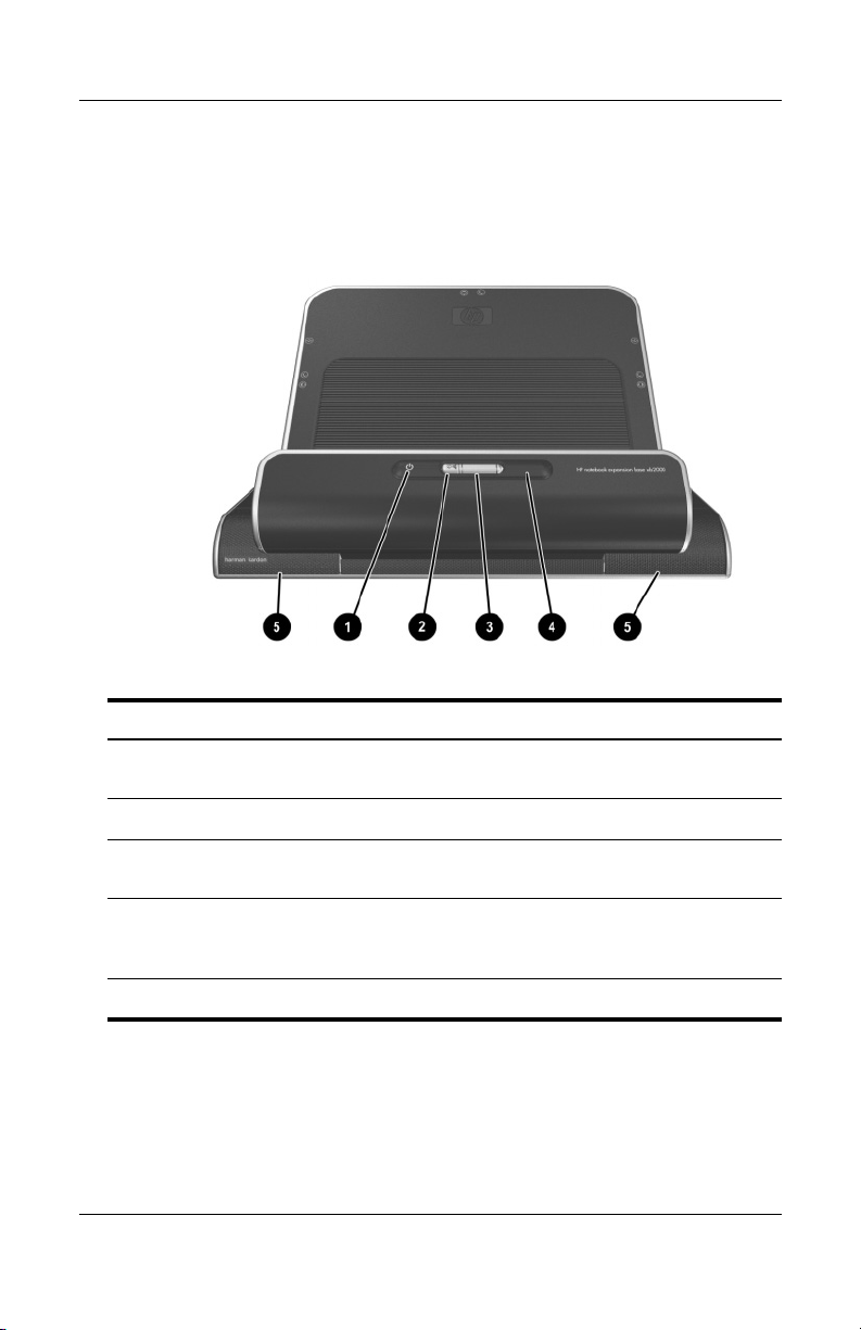
Identifying Components
Front
Component Description
Connection indicator
1
light
Mute button Mutes the sound from the notebook.
2
Volume scroll wheel Controls the volume of sound from the
3
Infrared lens Detects the notebook remote control infrared
4
Stereo speakers (2) Produce stereo sound.
5
1–2 Reference Guide
Illuminates solid blue when the notebook is
connected correctly.
notebook.
signal (not compatible with Microsoft®
Windows® Media Center Edition notebooks).
Page 7
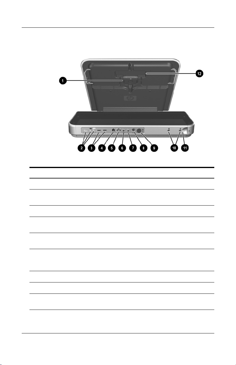
Rear
Component Description
Expansion cable Connects the Expansion Base to a notebook.
1
Power connectors (3) Connect the Expansion Base to notebook
2
USB ports (2) Connect USB devices; USB 2.0 compatible.
3
AC adapter.
Getting Started
RJ-11 (telephone) jack Connects the Expansion Base to an RJ-11
4
RJ-45 (network) jack Connects an Ethernet cable from the
5
S/PDIF (Sony/Philips
6
Digital Interface)
digital audio jack
Composite video jack Connects the Expansion Base to a television.
7
S-Video jack Connects the Expansion Base to a television.
8
Hard drive power
9
connector
Reference Guide 1–3
wall jack. (See also w).
Expansion Base to an RJ-45 wall jack.
Connects to a compatible audio/video receiver
through a digital coaxial cable.
Connects the power cord for the optional
internal hard drive.
(continued)
Page 8

Getting Started
Component Description
Kensington security
-
slots (2)
Hard drive carrier
q
screw
RJ-11 (telephone) jack Connects a modem cable from the
w
For more information on these components, refer to Chapter 2,
✎
“Using the Expansion Base.”
Connect optional security cables.
The purpose of security solutions
✎
is to act as a deterrent. These
solutions do not prevent the product
from being mishandled or stolen.
Secures the hard drive carrier.
Expansion Base to a notebook. (See also
4).
1–4 Reference Guide
Page 9
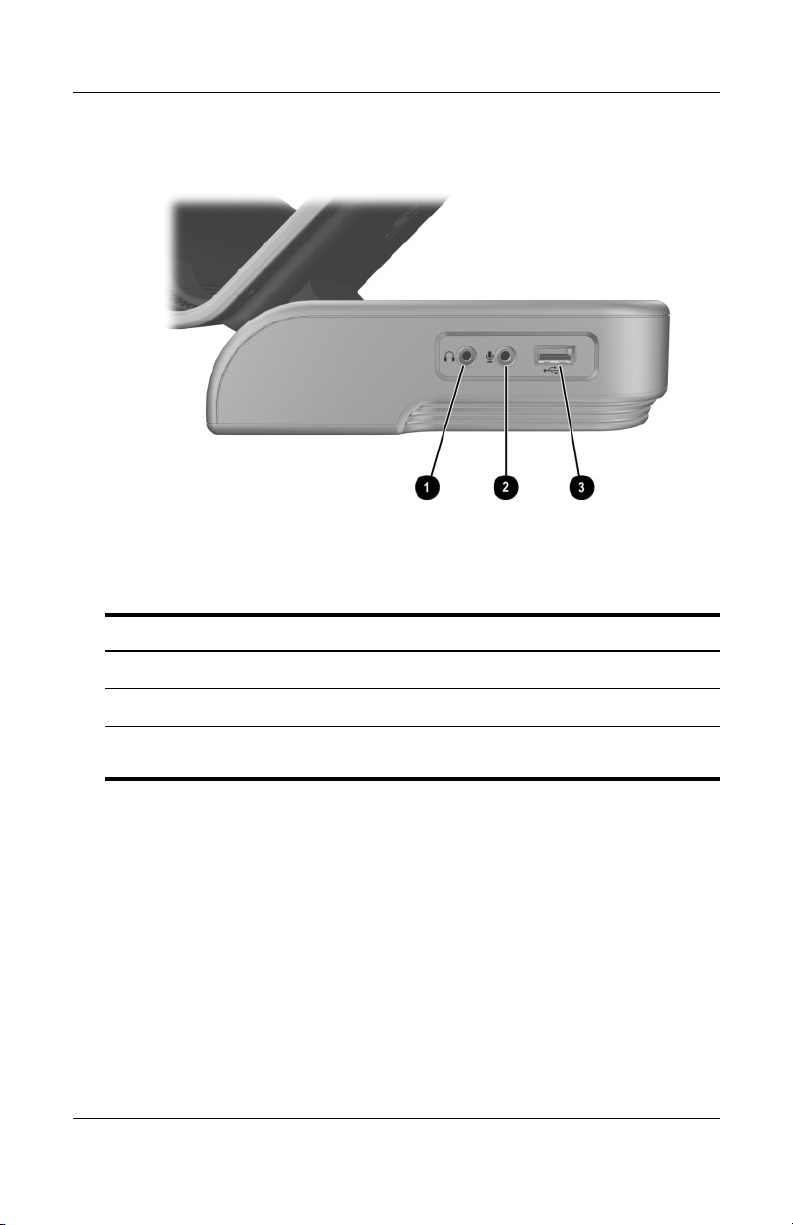
Right Side
Right side (viewed from the front of the Expansion Base)
Component Description
Getting Started
Audio-out (headphone) jack Connects a headphone.
1
Audio-in (microphone) jack Connects a microphone.
2
USB port Connects USB devices; USB 2.0
3
Reference Guide 1–5
compatible.
Page 10
Getting Started
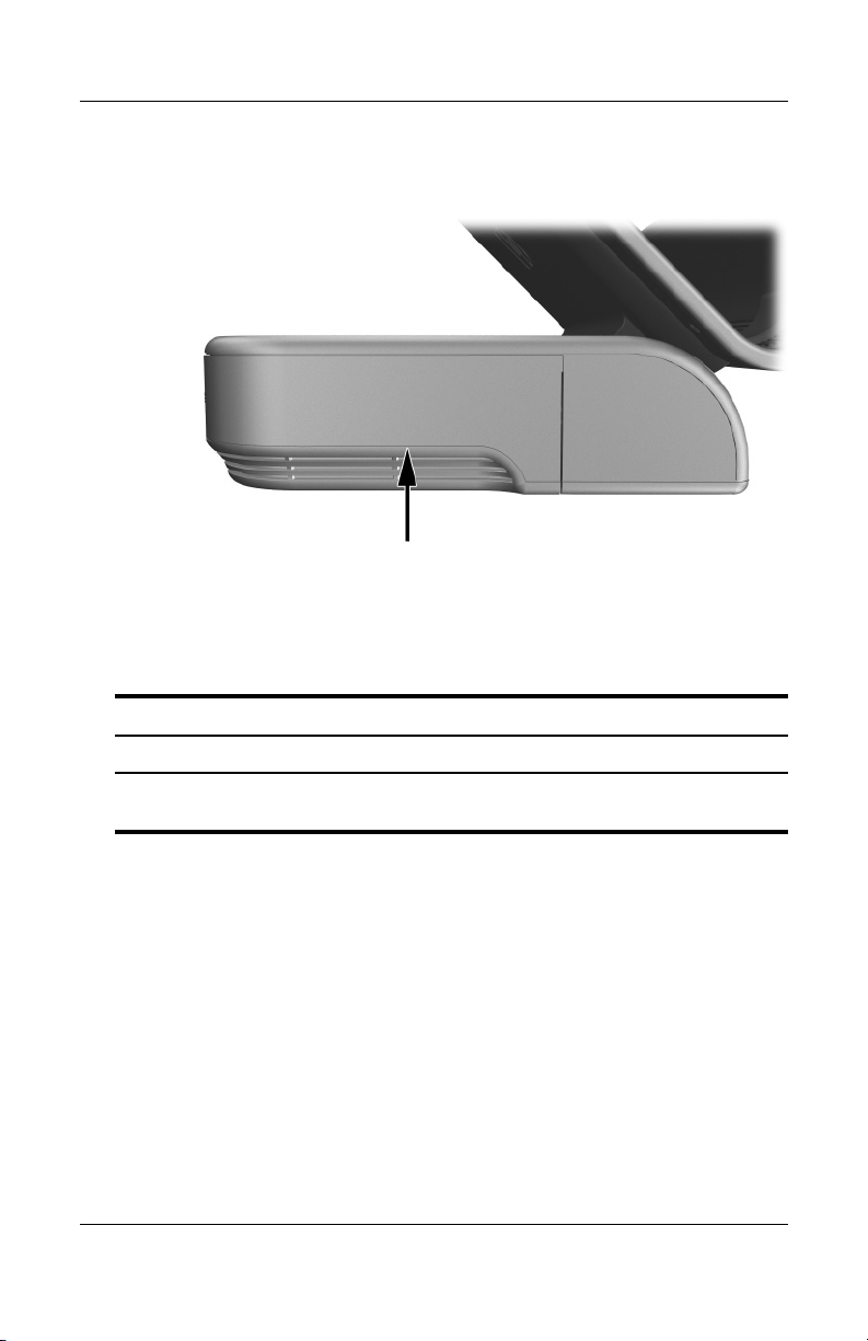
Left Side
Left side (viewed from the front of the Expansion Base)
Component Description
Hard drive carrier Holds an optional internal hard drive.
For information on installing an optional internal hard drive, refer to
✎
“Installing an Optional Hard Drive” in Chapter 2.
1–6 Reference Guide
Page 11
Getting Started
Setting Up the Expansion Base
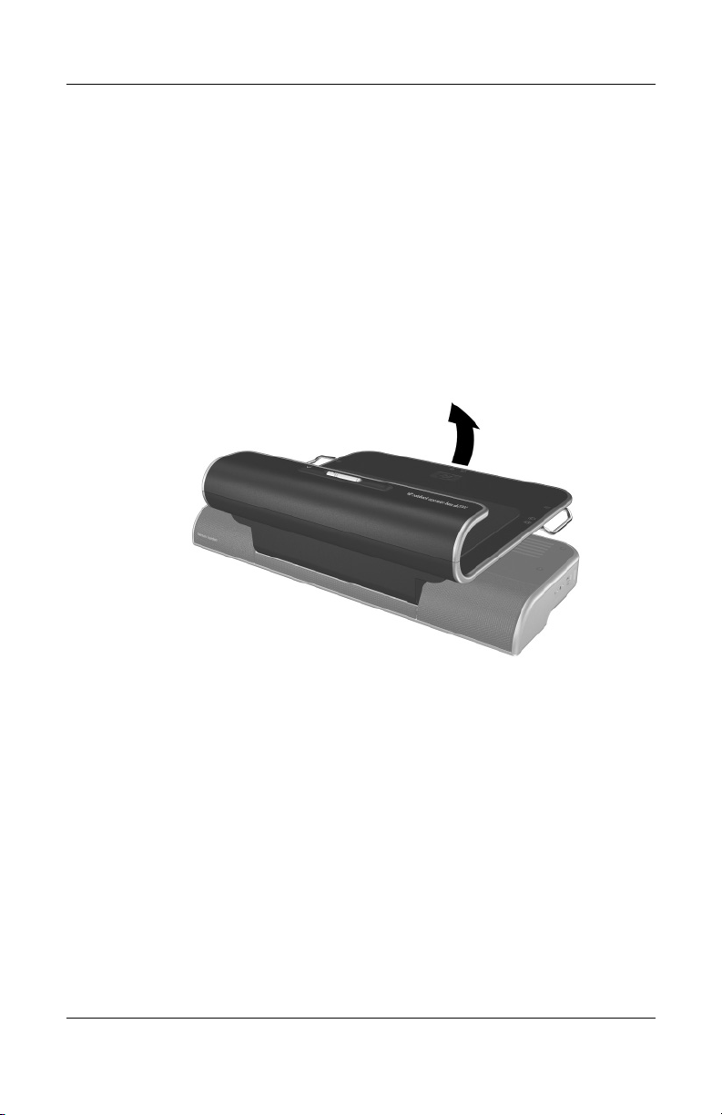
Step 1: Adjusting the Expansion Base
The Expansion Base must be upright before a notebook is
attached.
» To adjust the Expansion Base to an upright position, lift
the upper panel to the appropriate height.
Reference Guide 1–7
Page 12
Getting Started
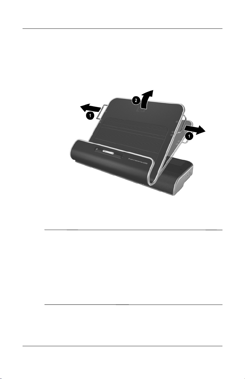
To lower the Expansion Base:
1. Pull out the handles on each side of the Expansion Base 1.
2. Grasp the handles and lower the upper panel of the
Expansion Base 2.
Step 2: Connecting to AC Power
WARNING: To reduce the risk of electric shock or damage to your
Å
equipment:
■ Plug the power cord into an electrical outlet that is easily accessible
at all times.
■ Disconnect power from the product by unplugging the power cord
from the electrical outlet.
■ If provided with a three-pin attachment plug on your power cord,
plug the cord into a grounded (earthed) three-pin outlet. Do not
disable the power cord grounding pin. The grounding pin is an
important safety feature.
1–8 Reference Guide
Page 13
Getting Started
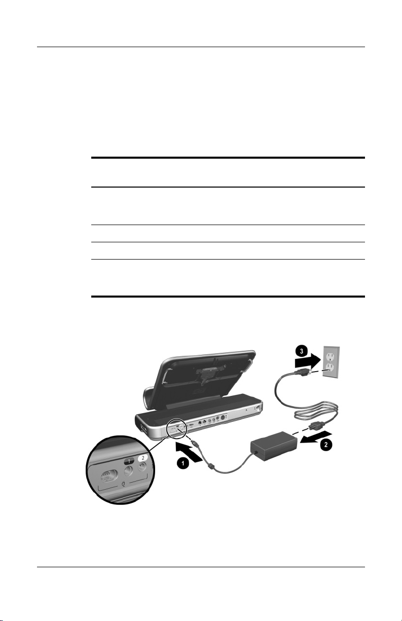
For optimal performance, connect the Expansion Base to an
AC power source using the notebook AC adapter and power cord.
1. Connect the notebook AC adapter to the matching connector
on the Expansion Base 1. Depending on your power
requirements, 3 power connectors are available on the rear
of the Expansion Base.
Connector
Type Color Label Power
Multi-pin No color Not labeled Multiple
(90 W
minimum)
Single-pin Blue/Black* 1 120 W, 135 W
Single-pin Yellow* 2 65 W
Some 90 W AC adapter connectors have yellow tips. If your
AC adapter cannot connect to the yellow connector on the
Expansion Base, use the blue/black connector.
2. Connect the AC power cord to the AC adapter 2, and then
to the wall outlet 3.
Power cords and power outlets vary by region and country
✎
Reference Guide 1–9
Page 14
Getting Started
Step 3: Connecting the Notebook
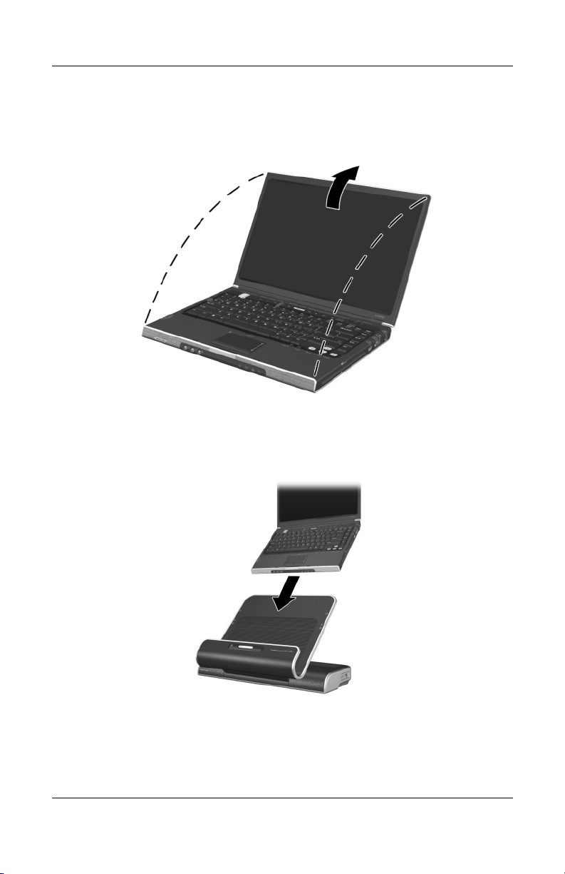
1. Open the notebook.
2. Slide the notebook into the Expansion Base with the
keyboard facing you.
The notebook is held in place by a buffer pad, which prevents
✎
the notebook from shifting out of its proper position in the
Expansion Base.
1–10 Reference Guide
Page 15
Getting Started
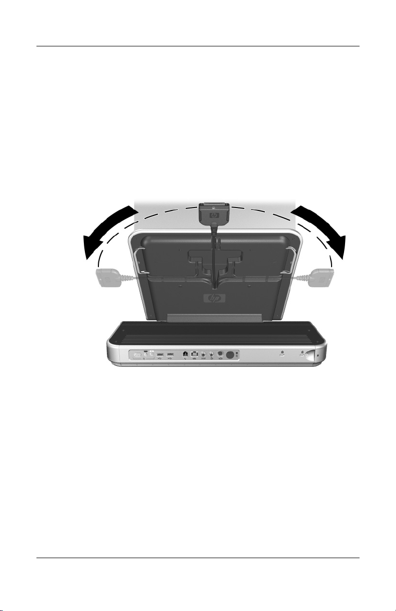
3. Gently pull the expansion cable from its docked location and
slide it to either side of the Expansion Base, depending on
where the expansion port on your notebook is located. The
location of the expansion port on your notebook may vary
by notebook series and model.
It is important to position the cable correctly, so that the cable
✎
can move freely. A cable skirt and guide assist in positioning
the cable.
Reference Guide 1–11
Page 16
Getting Started
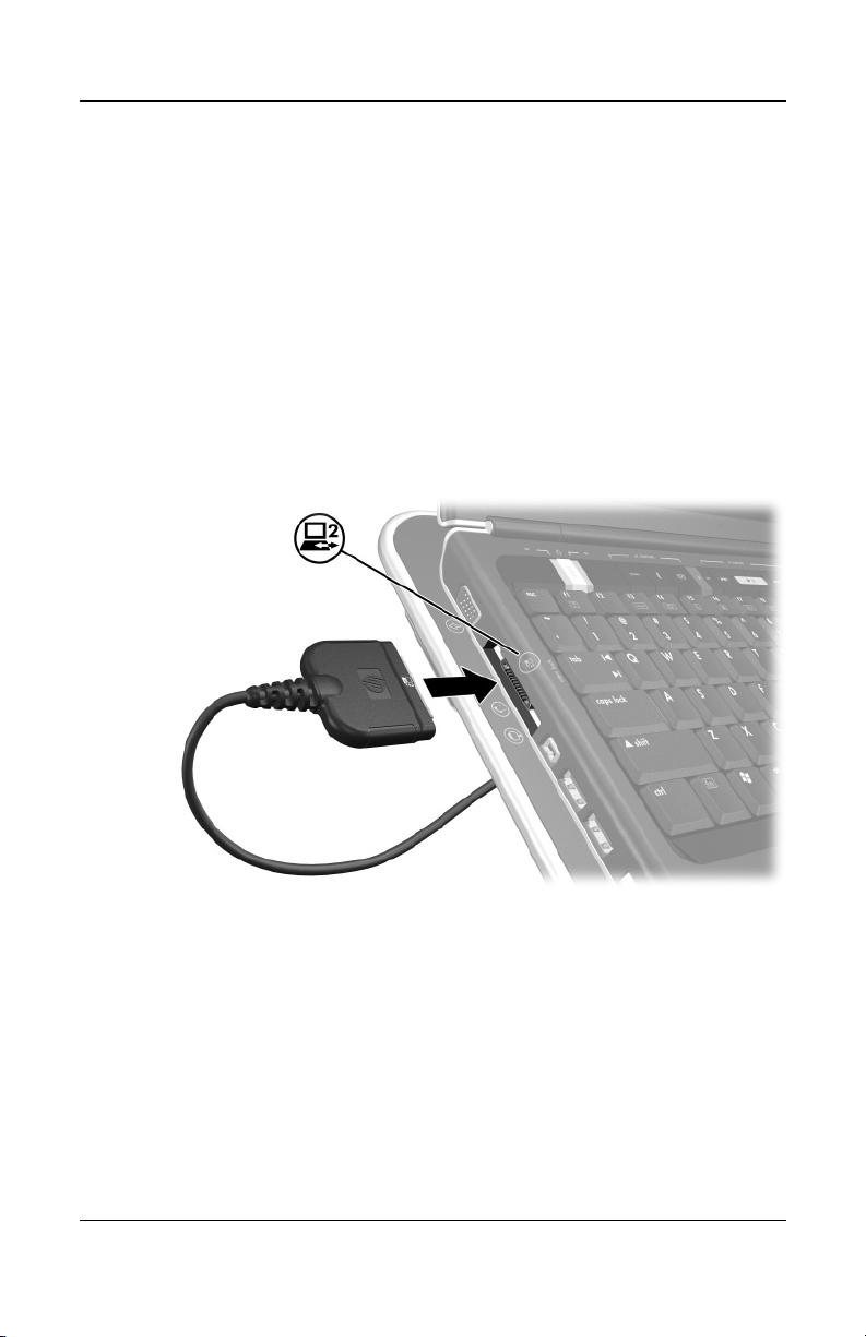
4. Connect the expansion cable to the notebook, matching
5. For optional communication, do one of the following:
the icon on the notebook expansion port with the icon
on the end of the expansion cable.
❏ If you are using a modem with your notebook to
communicate using an analog telephone line, refer
to “Connecting to a Modem” in Chapter 2.
❏ If you are connecting directly to a network, refer
to “Connecting to a Network” in Chapter 2.
1–12 Reference Guide
Page 17

Getting Started
6. If the notebook is not already turned on, press the power
button on the notebook to turn it on.
The power button location on the notebook may vary by
✎
notebook series and model.
Reference Guide 1–13
Page 18

Getting Started
If the notebook connection was made properly, the connection
indicator light will light up solid blue.
After the notebook is connected to the Expansion Base, the
✎
internal notebook speakers are disabled and the Expansion Base
speakers are activated.
1–14 Reference Guide
Page 19

Using the Expansion Base
Expansion Base Guidelines
■ Operating systems—For optimal performance, use the
Expansion Base with HP or Compaq notebooks running
Microsoft® Windows® XP or later.
■ Power—For optimal performance, use the Expansion Base
while connected to electrical power. This allows the notebook
battery to remain charged while the notebook is connected to
the Expansion Base.
■ Connecting and Removing
❏ With Windows XP or later, the notebook can be powered
on or off when connecting it to and removing it from the
Expansion Base. The blue connection indicator light on
the Expansion Base shows a successful connection and
will not be turned on until the notebook is powered on.
2
❏ With Windows versions prior to XP:
◆ Turn off the notebook before connecting it to and
removing it from the Expansion Base.
◆ When restoring power to the system, first connect
the notebook to the Expansion Base, and then turn
the notebook on.
■ External devices—When the notebook is connected to
the Expansion Base, you may attach external devices
to the connectors on the rear panel of the Expansion Base
or to the connectors on the notebook.
Reference Guide 2–1
Page 20

Using the Expansion Base
Optional Wireless Accessories
Component Description
Receiver Allows connection between the
1
Wireless keyboard Connects to the Expansion Base
2
Wireless mouse Connects to the Expansion Base
3
Batteries To be inserted into the wireless
4
The wireless accessories may be included with the
✎
Expansion Base.
2–2 Reference Guide
Expansion Base and the wireless
keyboard or mouse.
without a cable.
without a cable.
keyboard and mouse.
Page 21

Using the Expansion Base
Identifying the Wireless Receiver Buttons and Lights
Component Description
Caps lock light On: Keyboard caps lock has been
1
Num lock light On: Keyboard num lock has been
2
Connect button Connects wireless devices.
3
Keyboard battery light On: Keyboard battery has low
4
Mouse battery light On: Mouse battery has low or
5
Reference Guide 2–3
enabled.
enabled.
or no power.
no power.
Page 22

Using the Expansion Base
Connecting the Wireless Keyboard and Mouse
1. Turn the wireless keyboard upside down to locate the
battery cover 1.
2. Release the battery cover latch 2 and remove the battery
cover 3.
2–4 Reference Guide
Page 23

Using the Expansion Base
3. Insert a battery into the battery slot and push it into
the back of the slot 1.
4. Insert the second battery 2.
5. Replace the battery cover on the keyboard 3.
Reference Guide 2–5
Page 24

Using the Expansion Base
6. Remove the battery cover from the mouse.
7. Insert the batteries into the mouse 1.
8. Replace the battery cover 2.
2–6 Reference Guide
Page 25

Using the Expansion Base
9. Connect the wireless receiver to a USB port on the
Expansion Base.
Reference Guide 2–7
Page 26

Using the Expansion Base
10. Press the connect button on the receiver 1.
11. While the button on the receiver is flashing, press the
connect button on the bottom of the keyboard 2.
12. Turn the keyboard right-side up.
13. Wait 20 seconds.
2–8 Reference Guide
Page 27

Using the Expansion Base
14. If you are using the wireless mouse also, press the connect
button on the receiver again 1.
15. While the button on the receiver is flashing, press the
connect button on the bottom of the mouse 2.
Your wireless keyboard and mouse will now operate while
a notebook is connected to the Expansion Base.
Reference Guide 2–9
Page 28

Using the Expansion Base
Identifying the Wireless Keyboard Quick Launch Buttons
Component Description
Media Launches your default media player.
1
To select a default media player:
1. Select Start > Control Panel >
Add or Remove Programs >
Set Program Access and
Defaults > Custom.
2. Select the media player under
Choose a default media player.
Play/Pause Plays and pauses your default media
2
Mute Mutes the volume on the
3
Volume Controls the volume of the
4
Favorites Opens your Favorites folder.
5
Email Opens your email program.
6
World Wide Web Opens your Web browser.
7
2–10 Reference Guide
player while in use.
Expansion Base.
Expansion Base.
Page 29

Using the Expansion Base
Changing the Wireless Mouse Settings
To set pointer speed and shape, click speed, mouse trails, and
other preferences for your wireless mouse, select Start >
Control Panel > Printers and Other Hardware > Mouse.
Connecting to a Modem
You can connect your notebook through the Expansion Base
to your analog telephone line for dial-up communication.
This requires the 2 RJ-11 modem cables that came with your
Expansion Base.
1. Connect one end of the short modem cable into the RJ-11
(telephone) connector on the upper rear panel of the
Expansion Base 1. Connect the other end of the cable into
the RJ-11 connector on the notebook 2.
2. Connect one end of the long modem cable into the RJ-11
(telephone) connector on the lower rear panel of the
Expansion Base 3. Connect the other end of the cable
into the RJ-11 wall jack 4.
A country-specific modem adapter also may be required, in
✎
addition to the modem cable connected to the RJ-11 wall jack.
Reference Guide 2–11
Page 30

Using the Expansion Base
Connecting to a Network
You can connect your notebook through the Expansion Base
to a network. This requires an RJ-45 Ethernet cable (purchased
separately).
1. If you haven’t already done so, connect the Expansion Base
to your notebook following the instructions in Chapter 1,
“Getting Started.”
2. Connect one end of the Ethernet cable to the RJ-45
(network) jack on the Expansion Base 1 and the other
end to the RJ-45 wall jack 2.
Use the RJ-45 jack on the Expansion Base instead of the one
✎
on the notebook. The RJ-45 jack on some notebooks may be
disabled when the notebook is installed in the Expansion Base.
It is not necessary to connect a modem cable between
✎
the notebook and Expansion Base if you are connecting
the Expansion Base directly to a network.
2–12 Reference Guide
Page 31

Connecting Video
You can connect the Expansion Base to a television and use the
television as an external display. The Expansion Base provides
2 video-out ports on the rear panel, a composite video jack and
an S-Video jack. The S-Video connection provides better display
quality, but may not be available on all televisions. Refer to your
television documentation to determine if S-Video connection is
supported.
Composite Video Connection
To connect through composite video:
1. Connect a composite video cable (not included) into
the yellow composite video jack on the back of the
Expansion Base 1.
2. Connect the other end of the cable into the composite video
jack on your television 2. The location of the jack on your
television may vary by manufacturer and model.
Using the Expansion Base
Reference Guide 2–13
Page 32

Using the Expansion Base
3. Verify that your television is displaying the correct video
source. Refer to your television documentation for
instructions.
4. Press
fn+f4 on the notebook to change your video output
mode. Press
fn+f4 repeatedly to cycle through the available
video modes.
5. Refer to the instructions provided with your notebook to
configure the television as the primary display or to configure
advanced video features.
S-Video Connection
To connect through S-Video:
1. Connect an S-Video cable (not included) into the S-Video
jack on the back of the Expansion Base 1.
2. Connect the other end of the cable into the S-Video jack on
your television 2. Refer to your television documentation
for the connector location.
2–14 Reference Guide
Page 33

3. Verify that your television is displaying the correct video
source. Refer to your television documentation for
instructions.
4. Press
fn+f4 on the notebook to change your video output
mode. Press
fn+f4 repeatedly to cycle through the available
video modes.
5. Refer to the instructions provided with your notebook to
configure the television as the primary display or to configure
advanced video features.
Connecting Audio
The Expansion Base provides an S/PDIF digital audio jack for an
optional digital audio connection. A coaxial digital audio cable
(not provided) and an audio receiver (television or stereo) with a
coaxial digital audio port is required to fully enable this feature.
To connect digital audio:
1. Connect a coaxial digital audio cable into the orange S/PDIF
digital audio jack on the back of the Expansion Base 1.
Using the Expansion Base
2. Connect the other end of the cable into the digital audio jack
on your television or stereo equipment 2. Refer to your
television or stereo equipment documentation for the
connector name and location.
Reference Guide 2–15
Page 34

Using the Expansion Base
3. Enable the digital audio driver:
a. Double-click the speaker icon in your system tray.
(The Volume Control box opens).
b. Select Options > Advanced Controls.
c. Select Advanced.
d. Under Other Controls, select the check box for your
digital audio system.
e. Select Close.
f. Close the Volume Control box.
To experience digital audio with DVD playback:
1. Open InterVideo DVD by inserting a DVD or selecting
Start > All Programs > InterVideo DVD >
InterVideo DVD.
2. Right-click anywhere in the InterVideo DVD window to
open the control menu.
3. Select Setup > Audio > Digital (S/PDIF) out to
External Processor.
4. Select Apply > OK.
You must reenable analog audio anytime you wish to play a DVD
✎
without an S/PDIF connection.
Installing an Optional Hard Drive
You can install an optional hard drive into the Expansion Base
for extra storage capacity.
The Expansion Base supports IDE hard drives with an ATA-
✎
or ATAPI-compliant interface only. Refer to the hard drive
manufacturer's documentation.
2–16 Reference Guide
Page 35

Using the Expansion Base
Identify the following components that may be required
when you install an optional internal hard drive.
Component Description
Hard drive Provides optional internal storage.
1
Hard drive power cord Connects to an AC wall outlet.
2
Hard drive power adapter Connects to the hard drive power
3
Screws (6) Secure the optional internal hard drive
4
Hard drive carrier Holds the optional internal hard drive.
5
Depending on your configuration, some of the components
✎
listed above may not be provided or required.
Reference Guide 2–17
connector.
to the hard drive carrier. (Two extra
screws are provided).
(In some configurations, the hard drive
carrier will be preinstalled).
Page 36

Using the Expansion Base
1. Depending on your configuration, remove either the hard
drive carrier or the hard drive cover.
❏ To remove the hard drive carrier, remove the screw
located on the rear of the Expansion Base 1, and then
remove the hard drive carrier 2.
❏ To remove the hard drive cover, remove the screw located
on the rear of the Expansion Base 1, and then remove the
hard drive cover 2.
2–18 Reference Guide
Page 37

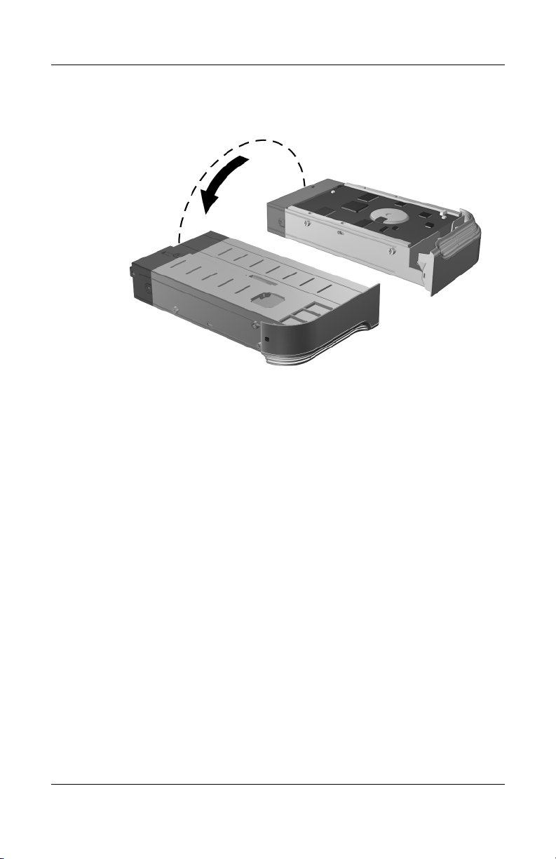
2. Turn the hard drive carrier over.
Using the Expansion Base
Reference Guide 2–19
Page 38

Using the Expansion Base
3. Connect the hard drive power cable 1 and the hard drive
data cable 2 to the hard drive.
4. Insert the hard drive into the hard drive carrier 3 and
secure the assembly with 2 screws on each side 4.
Two extra screws are provided.
✎
Be sure the optional hard drive is set to Cable Select.
✎
2–20 Reference Guide
Page 39
5. Turn hard drive carrier back over.
Using the Expansion Base
Reference Guide 2–21
Page 40

Using the Expansion Base
6. Replace the hard drive carrier 1 and hard drive carrier
screw 2.
7. Remove the hard drive power connector cover 3.
8. Connect the hard drive power adapter to the
Expansion Base 4.
9. Connect the power cord to the hard drive power adapter 5,
and then connect the power cord to the wall outlet 6.
For more information on the hard drive, refer to the instructions
✎
that came with the hard drive.
To remove the optional internal hard drive, reverse the installation
procedures.
2–22 Reference Guide
Page 41
Using the Expansion Base
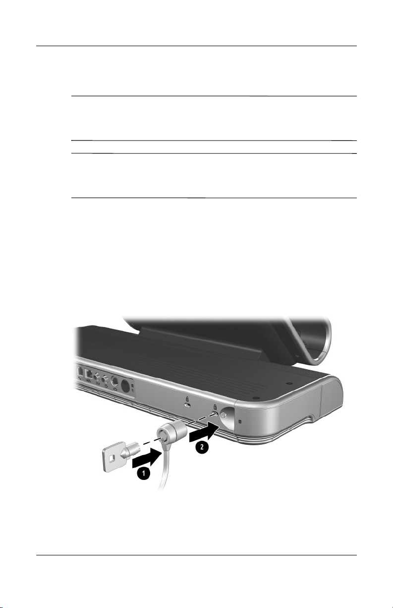
Connecting an Optional Security Cable
The purpose of security solutions is to act as a deterrent. These
✎
solutions do not prevent the product from being mishandled
or stolen.
Two Kensington security slots are provided. Use either security
✎
slot to connect an optional security cable and secure your
Expansion Base.
1. With the notebook positioned in the Expansion Base, loop the
security cable (purchased separately) around a secure object.
2. Insert the key into the security cable lock 1.
3. Insert the security cable lock into the Kensington security
slot on the Expansion Base 2.
4. Turn the key to secure the cable.
Reference Guide 2–23
Page 42

Removing the Notebook
It is not necessary to turn the notebook off before removing
✎
it from the Expansion Base if your operating system is
Windows XP or later.
1. Press the buttons on the sides of the expansion cable
connector 1 to disconnect the cable from the notebook 2.
The location of the expansion port on the notebook may vary
✎
by notebook series and model.
3
Reference Guide 3–1
Page 43

Removing the Notebook
2. Disconnect the modem cable from the RJ-11 (telephone) jack
on the notebook, if connected. You may leave the other end
of the cable connected to the Expansion Base for future use.
3. Slide the notebook up and out of the Expansion Base.
3–2 Reference Guide
Page 44

Troubleshooting
Getting More Information
■ The Documentation CD included with the notebook contains
comprehensive information about your notebook, as well as
governmental agency and safety information about the use
of your notebook.
■ The CD included with the Expansion Base contains
governmental agency and safety information about the use
of the Expansion Base.
■ The HP Web site (http://www.hp.com) provides product news
and software updates.
A
WARNING: To reduce the risk of serious injury, read the
Comfort Guide.
Å
health and work habits for computer users, and provides important
electrical and mechanical safety information. This guide is located on
the Web site at http://www.hp.com/ergo.
It describes proper workstation setup, posture, and
Safety &
Using the World Wide Web
Support services are available on the Internet through
Customer Care. You can either browse the postings as a guest,
or register as a user and submit your own questions. HP makes
every attempt to respond to questions in a timely manner.
To access Customer Care, visit the HP Web site at
http://www.hp.com/support.
Reference Guide A–1
Page 45

Troubleshooting
Preparing to Call Technical Support
If you cannot solve a problem using the troubleshooting tips in
this section, you may need to call Customer Care.
When you call technical support, have the following information
available:
■ The notebook and Expansion Base model types
■ Serial numbers for the notebook and Expansion Base
■ Purchase dates on invoices
■ Conditions under which the problem occurred
■ Error messages that have occurred
■ Hardware configuration of the notebook
■ Hardware and software you are using
■ Type of printer connected, if applicable
■ Configuration settings, including contents of the system files
A–2 Reference Guide
Page 46

Solving Common Problems
The following table lists possible problems, the possible cause
of each problem, and the recommended solutions.
Problem Possible Cause Solution
Troubleshooting
The blue connection
indicator light is
not on.
The speakers have
little or no volume.
The notebook
shuts down
unexpectedly.
The notebook is not
powered on.
The Expansion Base
is not connected to
AC power.
The expansion cable on
the Expansion Base is
not fully connected to the
expansion connector on
the notebook.
The notebook is
in Standby or
Hibernation mode.
The Expansion Base
speakers are muted or
the volume is set too low.
The Expansion Base
is not connected to
AC power, draining the
notebook battery pack.
Turn on the notebook.
Connect the Expansion Base
power cord to an AC power
outlet.
Disconnect the expansion
cable from the notebook, and
then connect the cable back
into the notebook.
Remove the notebook
from Standby or
Hibernation mode.
Adjust the volume scroll
wheel.
Connect the AC adapter from
the Expansion Base to an
AC power outlet.
(continued)
Reference Guide A–3
Page 47

Troubleshooting
Problem Possible Cause Solution
The wireless
keyboard or mouse
does not work.
A connected home
entertainment
system does not
have audio.
A connected home
entertainment
system does not
experience surround
sound.
The receiver is not
connected to an
available USB port.
The receiver and
keyboard or mouse have
not been synchronized.
The keyboard or mouse
has no battery power.
Audio not connected
properly.
The home entertainment
system may not support
digital audio.
Connect the receiver to a
USB port.
Synchronize the devices by
pressing the appropriate
buttons. Refer to “Optional
Wireless Accessories” in
Chapter 2.
Be sure that batteries are
inserted correctly in the
keyboard or mouse and that
the batteries are functional.
Be sure the Expansion Base
is properly connected to the
home entertainment system.
Refer to “Connecting Audio”
in Chapter 2.
Be sure your home
entertainment system is
S/PDIF compatible.
A–4 Reference Guide
Page 48

Index
A
AC adapter 1–9
AC power cord
AC power, connecting
additional information
adjusting height of Expansion Base
1–7
audio
connecting
troubleshooting
audio receiver
audio-in (microphone) jack
audio-out (headphone) jack
1–9, 2–22
1–8
A–1
2–15
A–4
2–15
1–5
1–5
B
batteries
identifying
wireless keyboard, inserting
2–4
wireless mouse, inserting
buttons
connect, wireless receiver
email
Favorites
Media
mute
power, notebook
QuickLaunch
2–2
2–6
2–3
2–10
2–10
2–10
1–2, 2–10
1–13
2–10
volume
wireless keyboard connect
wireless mouse connect
wireless receiver connect
World Wide Web
C
cables
coaxial digital audio
composite video
Ethernet
expansion
modem
S-Video
caps lock light
coaxial digital audio cable
components, identifying
composite video cable
composite video jack
connecting video
identifying
connect button, wireless receiver
2–3
connecting
AC power
audio
modem
network
2–10
2–10
2–13
2–12
1–3
2–11, 2–12
2–14
2–3
2–13
1–3
1–8
2–15
2–11
1–12, 2–12
2–8
2–9
2–8
2–15
2–15
1–2
2–13
Reference Guide Index–1
Page 49

Index
television 2–13
2–13
video
wireless receiver
connection indicator light
identifying
not illuminated
connectors
hard drive power
1–3
power
2–7
1–2
A–3
1–3
D
dial-up communication 2–11
digital audio driver, enabling
digital audio jack, Sony/Philips
Digital Interface (S/PDIF)
digital audio, connecting
documentation
DVD playback, digital audio
A–1
2–16
1–3
2–15
2–16
E
email button 2–10
Ethernet cable
expansion cable
connecting to notebook
disconnecting from notebook
3–1
identifying
positioning
expansion port, notebook
external devices
2–12
1–12
1–3
1–11
1–11
2–1
F
Favorites button 2–10
G
governmental agency information
A–1
guidelines
2–1
H
handles, adjusting height 1–7
hard drive carrier
identifying
installing
removing
hard drive carrier screw
identifying
removing
hard drive power adapter
hard drive power connector
hard drive power cord
hard drive, installing
headphone jack
height, adjusting
HP Web site
1–6, 2–17
2–22
2–18
1–4
2–18
1–5
1–7
A–1
I
infrared lens 1–2
installing hard drive
InterVideo DVD
2–16
J
jacks
audio, Sony/Philips Digital
Interface (S/PDIF)
composite video
headphone
microphone
1–3
1–5
1–5
2–17
1–3
2–17
2–16
2–16
1–3
Index–2 Reference Guide
Page 50

Index
RJ-11 (telephone) 1–3
RJ-45 (network)
S/PDIF digital audio
S-Video
1–3
1–3
K
Kensington security slots
identifying
using
keyboard battery light
keyboard, wireless
does not work
identifying
QuickLaunch buttons
using
1–4
2–23
2–3
A–4
2–2
2–4
L
left-side components 1–6
lights
caps lock
connection indicator
keyboard battery
mouse battery
num lock
wireless receiver
lowering Expansion Base
2–3
2–3
2–3
2–3
2–3
M
Media button 2–10
microphone jack
modem
connecting to
1–12
using
modem adapter
1–5
2–11
2–11
1–3
2–10
1–2
1–8
modem cable
connecting modem
connecting to network
disconnecting
mouse battery light
mouse, wireless
does not work
identifying
settings
using
mute button
2–2
2–11
2–4
1–2, 2–10
2–11
2–12
3–2
2–3
A–4
N
network, connecting Expansion
1–12, 2–12
Base
notebook
connecting expansion cable
1–12
opening
removing from Expansion Base
shuts down, troubleshooting
turning on
num lock light
1–10
3–1
A–3
1–13
2–3
O
opening notebook 1–10
operating systems
2–1
P
ports
1–3, 1–5
USB
power
connecting
guidelines
1–8
2–1
Reference Guide Index–3
Page 51

Index
power button, notebook 1–13
power connectors
identifying
voltages
power cord
1–3
1–9
1–9, 2–22
Q
QuickLaunch buttons 2–10
R
receiver, wireless
connect button
connecting
identifying
2–3
lights
remote control, notebook
removing notebook
right-side components
RJ-11 (telephone) jack
connecting modem cable
disconnecting modem cable
3–2
identifying
RJ-45 (network) jack
connecting network cable
identifying
RJ-45 Ethernet cable
2–3
2–7
2–2
1–2
3–1
1–5
1–3
1–3
2–12
S
S/PDIF (Sony/Philips Digital
Interface) digital audio jack
connecting audio
identifying
safety information
screw, hard drive carrier
2–15
1–3
A–1
1–4
2–11
2–12
security cables
Sony/Philips Digital Interface
(S/PDIF) digital audio jack
connecting audio
identifying
speakers
activating
identifying
volume problems
stereo, connecting audio
support services
S-Video cable
S-Video jack
connecting video
identifying
2–23
2–15
1–3
1–14
1–2
A–3
2–15
A–1
2–14
2–14
1–3
T
technical support A–2
television
composite video jack
connecting
connecting audio
S-Video jack
troubleshooting
turning on the notebook
2–13
1–3
A–1
1–3
2–15
1–13
U
USB ports 1–3, 1–5
V
video, connecting 2–13
volume button
volume problems
volume scroll wheel
2–10
A–3
1–2
Index–4 Reference Guide
Page 52

W
Web sites
A–1
HP
HP Customer Care Center
safety information
wireless accessories
wireless keyboard
does not work
identifying
QuickLaunch buttons
using
wireless mouse
does not work
identifying
settings
using
wireless receiver
connect button
connecting
identifying
lights
World Wide Web button
2–2
2–4
2–2
2–11
2–4
2–7
2–2
2–3
A–1
2–2
A–4
A–4
2–3
Index
A–1
2–10
2–10
Reference Guide Index–5
 Loading...