

HP Compaq Presario 12XL202, Compaq Presario 12XL203, Compaq Presario 12XL205, Compaq Presario 12XL212, Compaq Presario 12XL222 Service Guide
Page 1
Presario 1200 Series
Model XL2, XL201, XL202, XL203, XL204, XL205, XL212, XL220, XL222, XL223,
XL3, XL301, XL302, XL303, XL304, XL305, XL307, XL310, XL311,
XL312, XL314, XL320, XL323, XL325, XL326, XL327, XL330
Before You
Begin
Pin
Assignments
Removal
Sequence
Product
Description
Battery & Power
Management
Parts
Catalog
Specifications
Troubleshooting
MSG Index
Welcome to the Maintenance & Service Guide (MSG)
Welcome to the Maintenance and Service Guide (MSG) for Compaq Presario 1200XL Series Portable
Notebooks. This online guide is designed to serve the needs of technicians whose job is to repair
Compaq products.
For copyright and trademark information, refer to the Notice
unit’s serial number, to see symbol conventions, or to view technician’s notes, see the Preface
section of this MSG. To locate your
. This
MSG is updated periodically online as needed.
For comments or questions about the contents of this MSG, contact Compaq
.
To report a technical problem, contact your Regional Support Center or IM Help Center.
For help on navigating in this guide, refer to Using this Guide
P
RESARIO NOTEBOOK MAINTENANCE AND SERVICE GUIDE
1200 S
ERIES
.
W
ELCOME TO THE MAINTENANCE
& S
ERVICE GUIDE
(MSG) 1
Page 2

Presario 1200 Series
Model XL2, XL201, XL202, XL203, XL204, XL205, XL212, XL220, XL222, XL223,
XL3, XL301, XL302, XL303, XL304, XL305, XL307, XL310, XL311,
XL312, XL314, XL320, XL323, XL325, XL326, XL327, XL330
Using this Guide
To effectively use this guide, refer to the list of bookmarks at the left of the screen. These
bookmarks help you navigate through the document quickly and easily. They are accessible from
anywhere in the Maintenance and Service Guide (MSG).
Viewing a Chapter
Click one of the bookmarks or one of the color-coded bubbles on the Welcome page to view a
chapter of this MSG.
Expanding & Hiding Topics
Click the + to expand or show the contents of a section, or click the – to hide the contents.
Opening another Chapter
Return to the Welcome page
by clicking the bookmark, 1200 Series Maintenance and Service
Guide, and then click the bookmark or color-coded bubble for another chapter.
Printing the MSG
For portable copies of this MSG, you can print single pages, multiple pages, or the entire guide. In
the Acrobat Reader, click File, and then Print... for printing options.
P
RESARIO NOTEBOOK MAINTENANCE AND SERVICE GUIDE
1200 S
ERIES
W
ELCOME TO THE MAINTENANCE
& S
ERVICE GUIDE
(MSG) 2
Page 3

Presario 1200 Series
Model XL2, XL201, XL202, XL203, XL204, XL205, XL212, XL220, XL222, XL223,
XL3, XL301, XL302, XL303, XL304, XL305, XL307, XL310, XL311,
XL312, XL314, XL320, XL323, XL325, XL326, XL327, XL330
Before You Begin
Notice
The information in this guide is subject to change without notice.
COMPAQ COMPUTER CORPORATION SHALL NOT BE LIABLE FOR TECHNICAL OR EDITORIAL ERRORS
OR OMISSIONS CONTAINED HEREIN, NOR FOR INCIDENTAL OR CONSEQUENTIAL DAMAGES
RESULTING FROM THE FURNISHING, PERFORMANCE, OR USE OF THIS MATERIAL.
This guide contains information protected by copyright. No part of this guide may be photocopied or
reproduced in any form without prior written consent from Compaq Computer Corporation.
© 2000 Compaq Computer Corporation.
All rights reserved. Printed in the U.S.A.
Compaq, Presario 1200 Series Registered U. S. Patent and Trademark Office.
Microsoft, MS-DOS, and Windows are registered trademarks of Microsoft Corporation.
Windows 98 and Windows 2000 are trademarks of Microsoft
Corporation.
The software described in this guide is furnished under a license agreement or nondisclosure
agreement. The software may be used or copied only in accordance with the terms of the
agreement.
Product names mentioned herein may be trademarks and/or
registered trademarks of their respective companies.
Maintenance and Service Guide
Compaq Presario 1200 Series Notebook Computer
First Edition (July 2000) Compaq Computer Corporation
P
RESARIO NOTEBOOK MAINTENANCE AND SERVICE GUIDE
1200 S
ERIES
B
EFORE YOU BEGIN
1
Page 4

Presario 1200 Series
Model XL2, XL201, XL202, XL203, XL204, XL205, XL212, XL220, XL222, XL223,
XL3, XL301, XL302, XL303, XL304, XL305, XL307, XL310, XL311,
XL312, XL314, XL320, XL323, XL325, XL326, XL327, XL330
Preface
This Maintenance and Service Guide is a troubleshooting guide that is used as a reference guide
when servicing the Compaq Presario 1200 Series Notebook Computers.
Compaq Computer Corporation reserves the right to make changes to the Compaq Presario 1200
Series Notebooks without notice.
Symbols
The following words and symbols mark special messages throughout this guide.
WARNING: Text set off in this manner indicates that a failure to follow directions
Å
in the warning could result in bodily harm or loss of life.
CAUTION:
Ä
Ä
ÄÄ
could result in damage to equipment or loss of data.
Important: Text set off in this manner preseats clarifying information or specific
instructions.
Note: Text set off in this manner presents commentary, sidelights, or interesting
points of information.
Technician Notes
WARNING: Only authorized technicians trained by Compaq should repair this
Å
equipment. All troubleshooting and repair procedures are detailed to allow only
subassembly/module level repair. Because of the complexity of the individual
boards and subassemblies, the user should not attempt to make repaires at the
component level or to make modifications to any printed circuit board. Improper
repairs can create a safety hazard. Any indications of component replacement or
printed circuit board modifications may void any warranty.
Serial Number
When requesting information or ordering spare parts, you should provide the Notebook serial
number to Compaq. The serial number location
Text set off in this manner indicates that a failure to follow directions
is underneath the Notebook.
2 B
EFORE YOU BEGIN
P
RESARIO NOTEBOOK MAINTENANCE AND SERVICE GUIDE
1200 S
ERIES
Page 5

Presario 1200 Series
Model XL2, XL201, XL202, XL203, XL204, XL205, XL212, XL220, XL222, XL223,
XL3, XL301, XL302, XL303, XL304, XL305, XL307, XL310, XL311,
XL312, XL314, XL320, XL323, XL325, XL326, XL327, XL330
Locating Additional Information
The following documentation is available to support this product:
•
Compaq Presario 1200XL Series Notebook Computer documentation set
•
Introducing Windows 98 Guide
•
Introducing Windows 2000 Guide
•
Service Training Guides
•
Compaq Service Advisories and Bulletins
•
Compaq QuickFind
•
Compaq Service Quick Reference Guide
P
RESARIO NOTEBOOK MAINTENANCE AND SERVICE GUIDE
1200 S
ERIES
B
EFORE YOU BEGIN
3
Page 6
Presario 1200 Series
Model XL2, XL201, XL202, XL203, XL204, XL205, XL212, XL220, XL222, XL223,
XL3, XL301, XL302, XL303, XL304, XL305, XL307, XL310, XL311,
XL312, XL314, XL320, XL323, XL325, XL326, XL327, XL330
Product Description
Models and Features
XL2, XL201-205
Compaq Presario 1200 Series Portable Notebook Computer Models
Feature XL2 XL201 XL202
Display 12.1-in HPA 12.1-in HPA 12.1-in HPA
Processor
Hard Drive 5.0 GB 5.0 GB 5.0 GB
CD or DVD 24X CD-Rom 24X CD-Rom 24X CD-Rom
Diskette
Drive
Modem
Battery 3.8 NiMH 3.8 NiMH 3.8 NiMH
System
Memory
Feature XL203 XL204 XL205
Display 12.1-in HPA 13.0-in HPA 12.1-in HPA
Processor Cel/566(128)
Hard Drive 5.0 GB 5.0 GB 5.0 GB
CD or DVD 24X CD-Rom 24X CD-Rom 24X CD-Rom
Diskette
Drive
Modem 56K Mini PCI d/f 2
Battery 3.8 NiMH 3.8 NiMH 3.8 NiMH
System
Memory
Cel/566(128)
FCPGA
1.44 Std. Diskette 1.44 Std. Diskette 1.44 Std. Diskette
56K Mini PCI
d/f 1, Bear*
32 MB 32 MB 64 MB
FCPGA
1.44 Std. Diskette 1.44 Std. Diskette 1.44 Std. Diskette
Seminole*
32 MB 32 MB 64 MB
Cel/566(128)
FCPGA
56K Mini PCI
d/f 1, Bear*
Cel/566(128)
FCPGA
56K Mini PCI
d/f 1, Bear*
Cel/566(128)
FCPGA
56K Mini PCI d/f 2,
Seminole*
Cel/566(128)
FCPGA
56K Mini PCI
d/f 2&3*
*See Modem Legend
Additional Models on Next Page
P
RESARIO NOTEBOOK MAINTENANCE AND SERVICE GUIDE
1200 S
ERIES
P
RODUCT DESCRIPTION
1
Page 7
Presario 1200 Series
Model XL2, XL201, XL202, XL203, XL204, XL205, XL212, XL220, XL222, XL223,
XL3, XL301, XL302, XL303, XL304, XL305, XL307, XL310, XL311,
XL312, XL314, XL320, XL323, XL325, XL326, XL327, XL330
XL212-223
Compaq Presario 1200 Series Portable Notebook Computer Models
Feature XL212 XL220 XL222 XL223
Display 13.3-in TFT 13.0-in HPA 12.1-in TFT 13.3-in TFT
Processor
PIII/650(256)
FCPGA
Hard Drive 5.0 GB 6.0 GB 5.0 GB 6.0 GB
CD or DVD 24X CD-Rom 24X CD-Rom 24X CD-Rom DVD
Diskette
1.44 Std. Diskette 1.44 Std. Diskette 1.44 Std. Diskette 1.44 Std. Diskette
Drive
Modem
56K Mini PCI
d/f 2&3*
Battery 3.2 Li-ion 3.2 Li-ion 3.2 Li-ion 3.2 Li-ion
System
64 MB 64 MB 64 MB 64 MB
Memory
Cel/600(128)
FCPGA
Cel/566(128)
FCPGA
56K Mini PCI d/f 1* 56K Mini PCI d/f 2,
Seminole*
Cel/600(128)
FCPGA
56K Mini PCI d/f 1*
* Modem Legend
1) 56K Mini PCI d/f 1 = Bear/Grizzly Modem/NIC Combo = NA, CKK, LA
2) 56K Mini PCI d/f 2 = Seminole = EMEA/APD
3) 56K Mini PCI d/f 3 = Seminole 2 = All AUS/NZ
Additional Models on Next Page
2 P
RODUCT DESCRIPTION
P
RESARIO NOTEBOOK MAINTENANCE AND SERVICE GUIDE
1200 S
ERIES
Page 8
Presario 1200 Series
Model XL2, XL201, XL202, XL203, XL204, XL205, XL212, XL220, XL222, XL223,
XL3, XL301, XL302, XL303, XL304, XL305, XL307, XL310, XL311,
XL312, XL314, XL320, XL323, XL325, XL326, XL327, XL330
XL3, XL301-310
Compaq Presario 1200 Series Portable Notebook Computer Models
Feature XL3 XL301 XL302 XL303
Display 12.1-in HPA 12.1-in HPA 12.1-in HPA 12.1-in TFT
Processor
Cel/566(128)
FCPGA
Hard Drive 5.0 GB 5.0 GB 5.0 GB 6.0 GB or 10.0 GB
CD or DVD 24X CD-Rom 24X CD-Rom 24X CD-Rom 24X CD-Rom
Diskette
1.44 Std. Diskette 1.44 Std. Diskette 1.44 Std. Diskette 1.44 Std. Diskette
Drive
Modem
Battery
System
56K Mini PCI
d/f 1, Bear*
3.8 NiMH 3.8 NiMH 3.8 NiMH 3.2 Li-ion or
32 MB 64 MB 64 MB 64 MB
Memory
Feature XL304 XL305 XL307 XL310
Display
13.0-in HPA 12.1-in TFT 13.3-in TFT 12.1-in TFT
Processor Cel/600(128)
FCPGA
Hard Drive
6.0 GB 6.0 GB 6.0 GB or 10.0 GB 6.0 GB
CD or DVD 24X CD-Rom 24X CD-Rom 8X DVD 8X DVD
Diskette
1.44 Std. Diskette 1.44 Std. Diskette 1.44 Std. Diskette 1.44 Std. Diskette
Drive
Modem 56K Mini PCI
d/f 1, Bear*
Battery
System
3.8 NiMH 3.8 NiMH 3.2 Li-ion 3.2 Li-ion
64 MB 64 MB 64 MB 64 MB
Memory
Cel/600(128)
FCPGA
56K Mini PCI
d/f 1*
Cel/600(128)
FCPGA
56K Mini PCI
d/f 1&3*
Cel/600(128)
FCPGA
56K Mini PCI d/f 2,
Cel/600(128)
FCPGA
56K Mini PCI d/f 2*
Seminole*
3.8 NiMH
Cel/600(128)
FCPGA
Cel/600(128)
FCPGA
56K Mini PCI d/f 2* 56K Mini PCI d/f 1*
*See Modem Legend
Additional Models on Next Page
P
RESARIO NOTEBOOK MAINTENANCE AND SERVICE GUIDE
1200 S
ERIES
P
RODUCT DESCRIPTION
3
Page 9
Presario 1200 Series
Model XL2, XL201, XL202, XL203, XL204, XL205, XL212, XL220, XL222, XL223,
XL3, XL301, XL302, XL303, XL304, XL305, XL307, XL310, XL311,
XL312, XL314, XL320, XL323, XL325, XL326, XL327, XL330
XL311-325
Compaq Presario 1200 Series Portable Notebook Computer Models
Feature XL311 XL312 XL314
Display 13.3-in TFT 12.1-in TFT 13.3-in TFT
Processor Cel/700(256) FCPGA PIII/700(256) FCPGA PIII/700(256) FCPGA
Hard Drive 10.0 GB 6.0 GB 6.0 GB
CD or DVD 8X DVD 24X CD-Rom 24X CD-Rom
Diskette
Drive
Modem 56K Mini PCI d/f 1* 56K Mini PCI d/f 1&3* 56K Mini PCI d/f 1&3*
Battery 3.2 Li-ion 3.2 Li-ion 3.2 Li-ion
System
Memory
Feature XL320 XL323 XL325
Display 12.1-in TFT 13.3-in TFT 13.3-in TFT
Processor Cel/633(128) FCPGA Cel/633(128) FCPGA PIII/650(256) FCPGA
Hard Drive 6.0 GB 10.0 GB 6.0 GB
CD or DVD 24X CD-Rom 8X DVD 8X DVD
Diskette
Drive
Modem 56K Mini PCI d/f 1* 56K Mini PCI d/f 1* 56K Mini PCI d/f 1*
Battery 3.2 Li-ion 3.8 NiMH 3.2 Li-ion
System
Memory
1.44 Std. Diskette 1.44 Std. Diskette 1.44 Std. Diskette
64 MB 64 MB 64 MB
1.44 Std. Diskette 1.44 Std. Diskette 1.44 Std. Diskette
64 MB 64 MB 64 MB
* Modem Legend
1) 56K Mini PCI d/f 1 = Bear/Grizzly Modem/NIC Combo = NA, CKK, LA
2) 56K Mini PCI d/f 2 = Seminole = EMEA/APD
3) 56K Mini PCI d/f 3 = Seminole 2 = All AUS/NZ
Additional Models on Next Page
4 P
RODUCT DESCRIPTION
P
RESARIO NOTEBOOK MAINTENANCE AND SERVICE GUIDE
1200 S
ERIES
Page 10
Model XL2, XL201, XL202, XL203, XL204, XL205, XL212, XL220, XL222, XL223,
XL326-330
Feature XL326 XL327 XL330
Display 13.0-in HPA 13.0-in HPA 12.1-in TFT
Processor
Hard Drive 6.0 GB 6.0 GB 6.0 GB
CD or DVD 24X CD-Rom 24X CD-Rom 24X CD-Rom
Diskette
Drive
Modem
Battery 3.2 Li-ion 3.2 Li-ion 3.2 Li-ion
System
Memory
Presario 1200 Series
XL3, XL301, XL302, XL303, XL304, XL305, XL307, XL310, XL311,
XL312, XL314, XL320, XL323, XL325, XL326, XL327, XL330
Compaq Presario 1200 Series Portable Notebook Computer Models
Cel/600(128)
FCPGA
1.44 Std. Diskette 1.44 Std. Diskette 1.44 Std. Diskette
56K Mini PCI
d/f 1*
128 MB 64 MB 64 MB
Cel/633(128)
FCPGA
56K Mini PCI
d/f 1*
PIII/650(256)
FCPGA
56K Mini PCI d/f 1*
* Modem Legend
1) 56K Mini PCI d/f 1 = Bear/Grizzly Modem/NIC Combo = NA, CKK, LA
2) 56K Mini PCI d/f 2 = Seminole = EMEA/APD
3) 56K Mini PCI d/f 3 = Seminole 2 = All AUS/NZ
P
RESARIO NOTEBOOK MAINTENANCE AND SERVICE GUIDE
1200 S
ERIES
P
RODUCT DESCRIPTION
5
Page 11
Model XL2, XL201, XL202, XL203, XL204, XL205, XL212, XL220, XL222, XL223,
XL3, XL301, XL302, XL303, XL304, XL305, XL307, XL310, XL311,
XL312, XL314, XL320, XL323, XL325, XL326, XL327, XL330
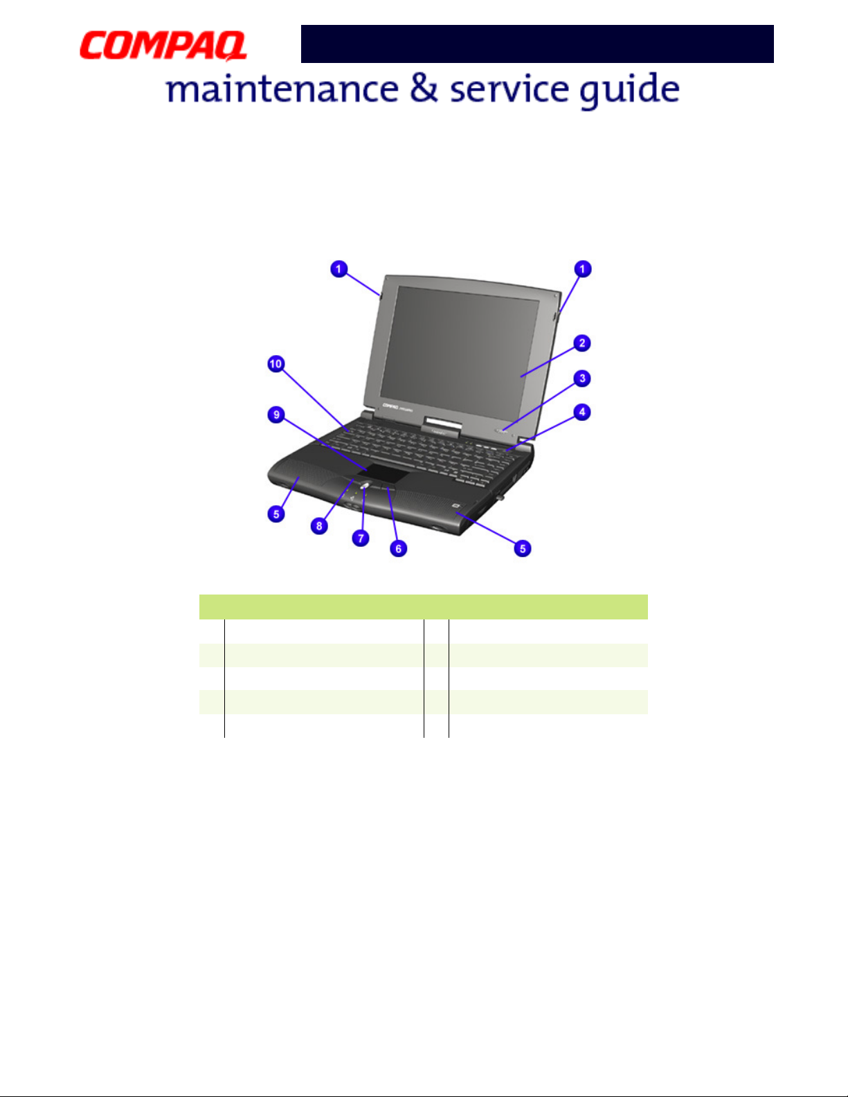
Front of Unit
Presario 1200 Series
Display Release Latch
1
Display
2
Power (On/Off) Button
3
Lid Switch
4
Speakers
5
Description
Right TouchPad Button
6
Scroll Button
7
Left TouchPad Button
8
TouchPad
9
Keyboard
-
6 P
RODUCT DESCRIPTION
P
RESARIO NOTEBOOK MAINTENANCE AND SERVICE GUIDE
1200 S
ERIES
Page 12
Presario 1200 Series
Model XL2, XL201, XL202, XL203, XL204, XL205, XL212, XL220, XL222, XL223,
XL3, XL301, XL302, XL303, XL304, XL305, XL307, XL310, XL311,
XL312, XL314, XL320, XL323, XL325, XL326, XL327, XL330
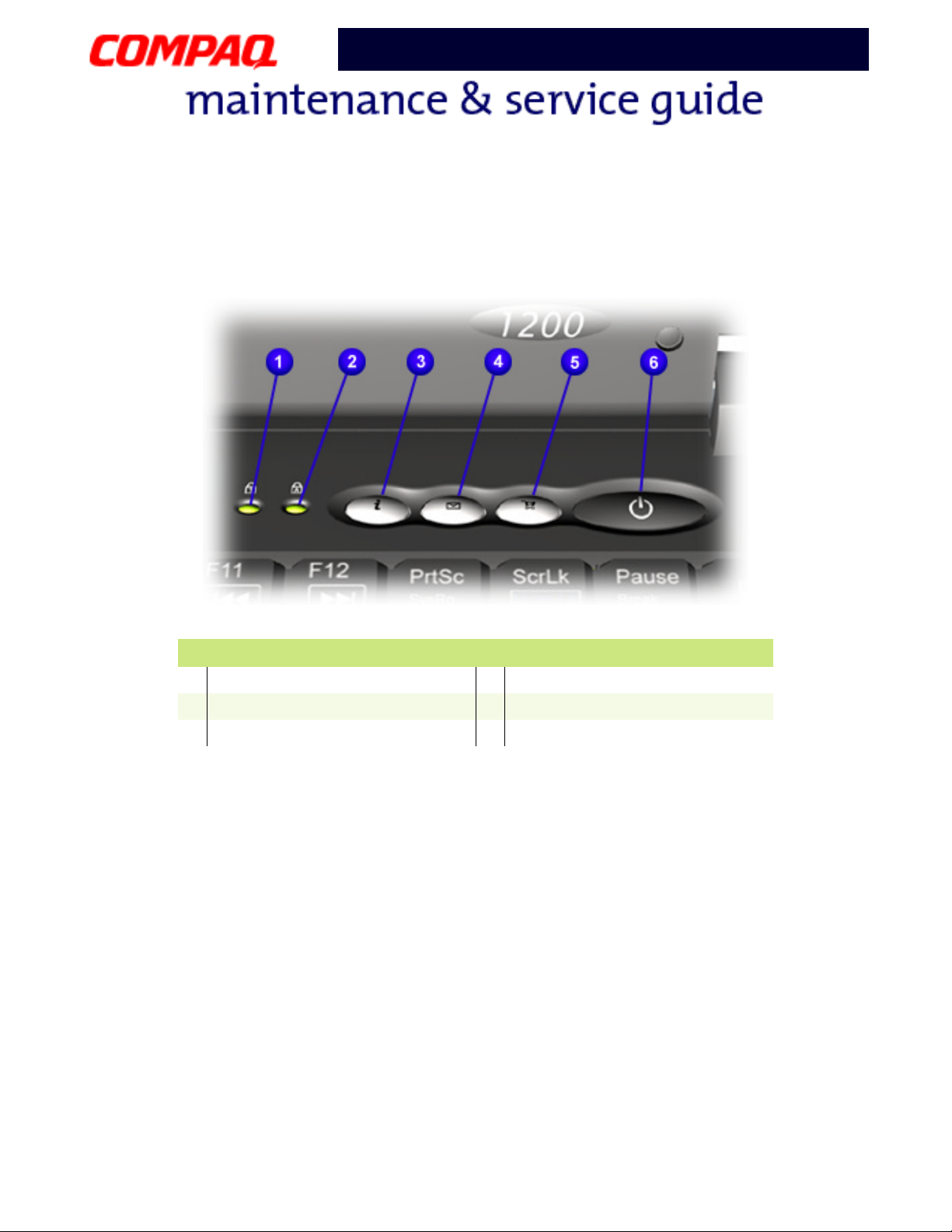
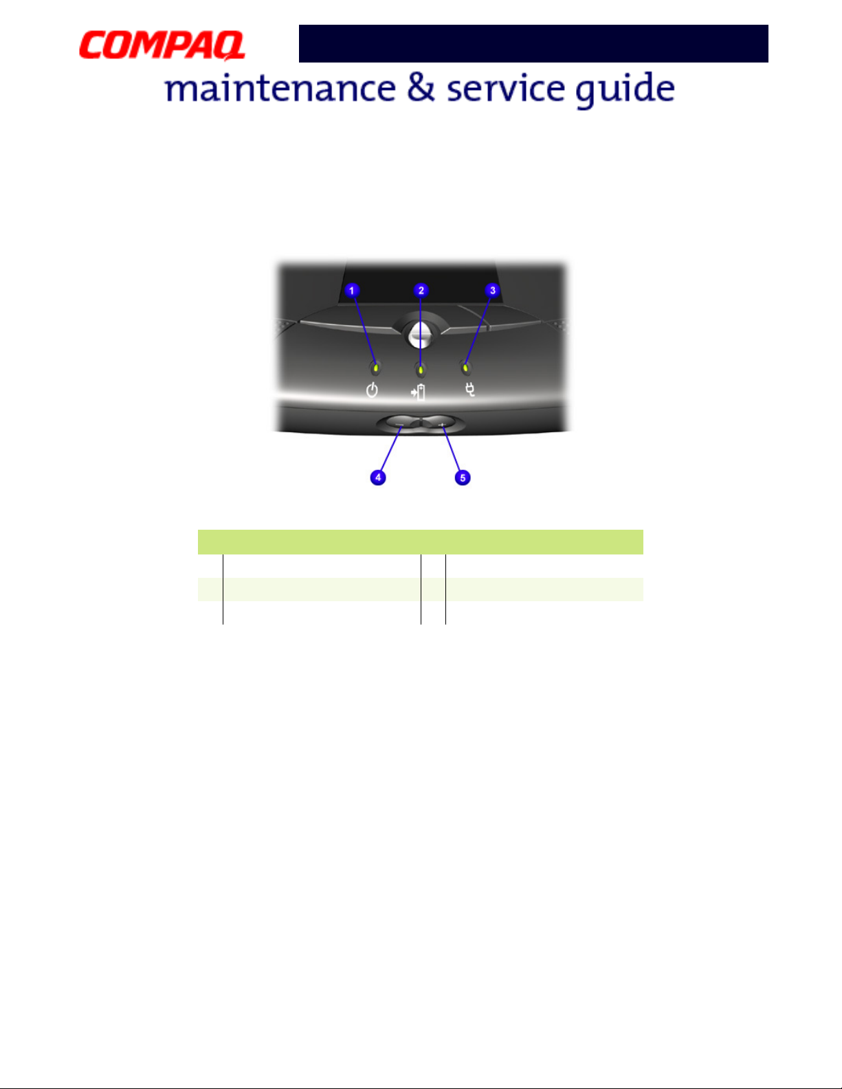
Internet Zone Buttons and Lights
Num Lock Light
1
Caps Lock Light
2
Instant Internet Access Button
3
Description
Instant E-mail Access Button
4
Retail Central Button
5
Power Button
6
P
RESARIO NOTEBOOK MAINTENANCE AND SERVICE GUIDE
1200 S
ERIES
P
RODUCT DESCRIPTION
7
Page 13
Presario 1200 Series
Model XL2, XL201, XL202, XL203, XL204, XL205, XL212, XL220, XL222, XL223,
XL3, XL301, XL302, XL303, XL304, XL305, XL307, XL310, XL311,
XL312, XL314, XL320, XL323, XL325, XL326, XL327, XL330
Front Bezel Components
Power (On/Off) Light
1
Battery Charge Light
2
AC Power Light
3
Description
Volume Down Button
4
Volume Up B utton
5
8 P
RODUCT DESCRIPTION
P
RESARIO NOTEBOOK MAINTENANCE AND SERVICE GUIDE
1200 S
ERIES
Page 14
Model XL2, XL201, XL202, XL203, XL204, XL205, XL212, XL220, XL222, XL223,
XL3, XL301, XL302, XL303, XL304, XL305, XL307, XL310, XL311,
XL312, XL314, XL320, XL323, XL325, XL326, XL327, XL330
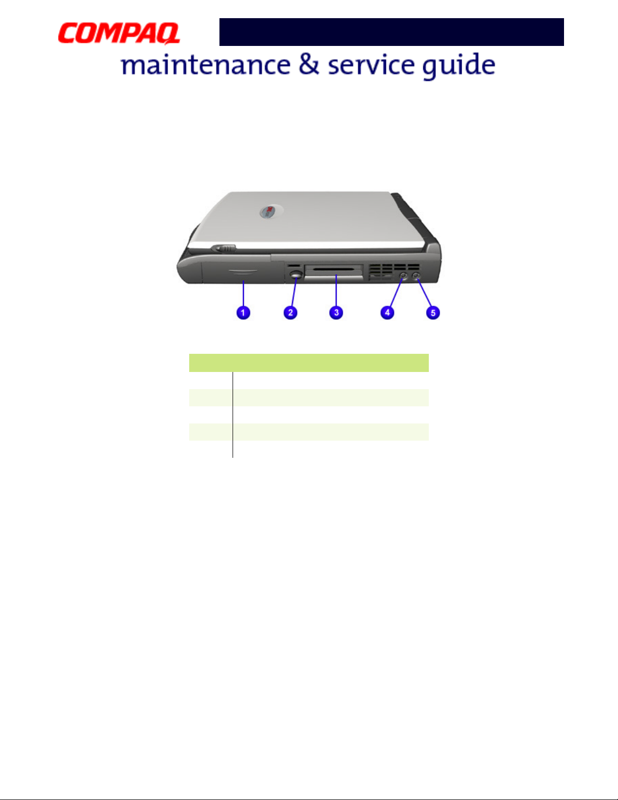
Right-Side Components
Presario 1200 Series
Description
1
2
3
4
5
Battery Compartment
PC Card Eject Button
PC Card Slot
Microphone Jack
Headphone Jack
P
RESARIO NOTEBOOK MAINTENANCE AND SERVICE GUIDE
1200 S
ERIES
P
RODUCT DESCRIPTION
9
Page 15
Model XL2, XL201, XL202, XL203, XL204, XL205, XL212, XL220, XL222, XL223,
XL3, XL301, XL302, XL303, XL304, XL305, XL307, XL310, XL311,
XL312, XL314, XL320, XL323, XL325, XL326, XL327, XL330
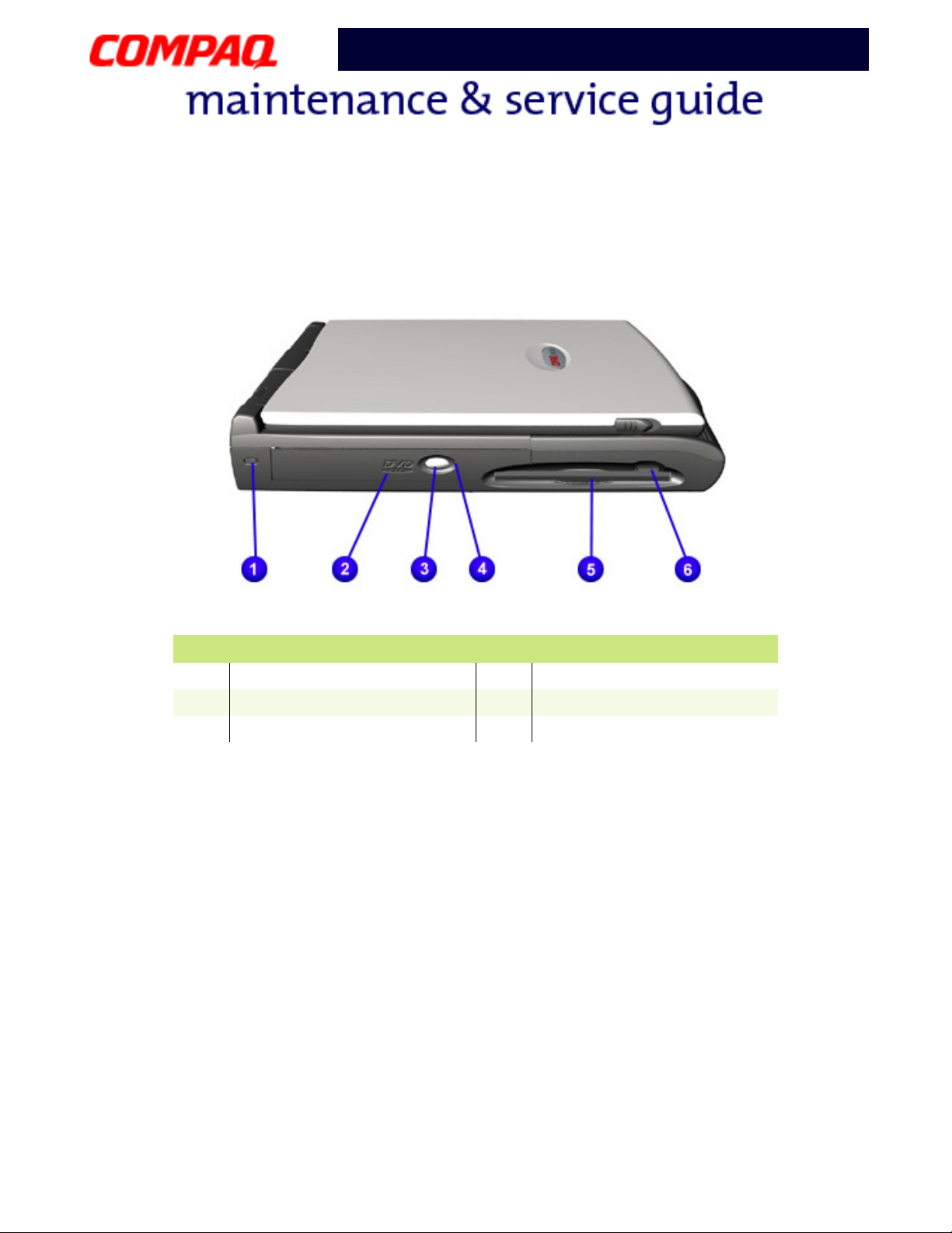
Left-Side Components
Presario 1200 Series
Security Slot
1
CD or DVD Player
2
CD/DVD Eject Button
3
Description
4
5
6
CD or DVD Manual Eject Hole
Diskette Drive
Diskette Drive Eject Button
10 P
RODUCT DESCRIPTION
P
RESARIO NOTEBOOK MAINTENANCE AND SERVICE GUIDE
1200 S
ERIES
Page 16
Model XL2, XL201, XL202, XL203, XL204, XL205, XL212, XL220, XL222, XL223,
XL3, XL301, XL302, XL303, XL304, XL305, XL307, XL310, XL311,
XL312, XL314, XL320, XL323, XL325, XL326, XL327, XL330
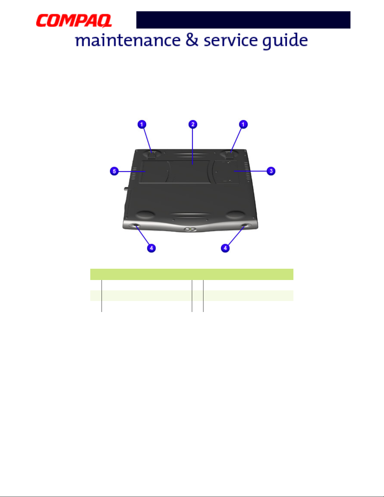
Underneath the Unit
Presario 1200 Series
Stand Feet
1
Serial and Model Number
2
Memory Compartment
3
Description
Speaker Ports
4
Modem Compartment
5
P
RESARIO NOTEBOOK MAINTENANCE AND SERVICE GUIDE
1200 S
ERIES
P
RODUCT DESCRIPTION
11
Page 17
Model XL2, XL201, XL202, XL203, XL204, XL205, XL212, XL220, XL222, XL223,
XL3, XL301, XL302, XL303, XL304, XL305, XL307, XL310, XL311,
XL312, XL314, XL320, XL323, XL325, XL326, XL327, XL330
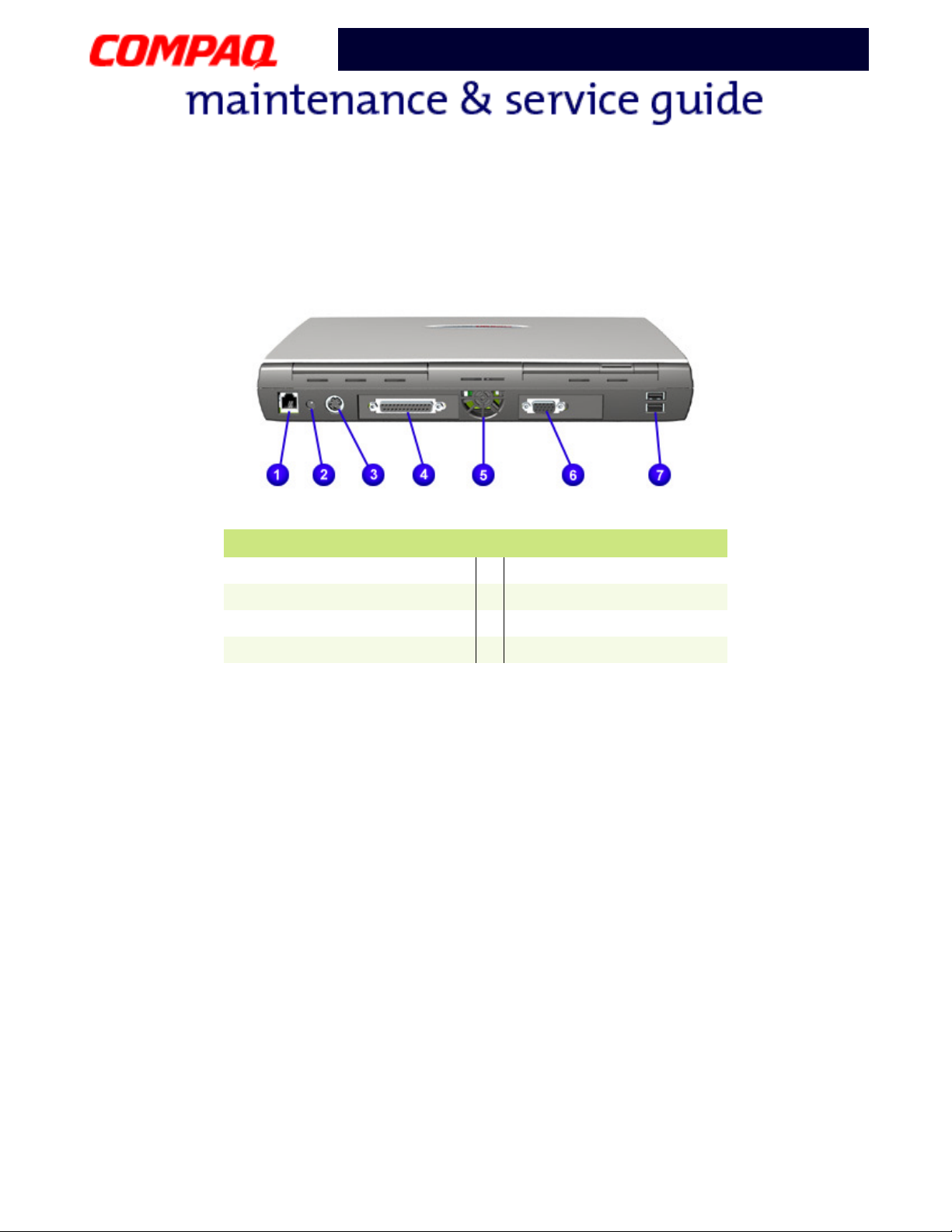
Rear Connectors
Presario 1200 Series
Description
Modem
1
AC Power
2
Keyboard/Mouse Port
3
Printer/Parallel Port
4
Fan Vent
5
VGA External Monitor
6
USB Ports
7
12 P
RODUCT DESCRIPTION
P
RESARIO NOTEBOOK MAINTENANCE AND SERVICE GUIDE
1200 S
ERIES
Page 18
Presario 1200 Series
Model XL2, XL201, XL202, XL203, XL204, XL205, XL212, XL220, XL222, XL223,
XL3, XL301, XL302, XL303, XL304, XL305, XL307, XL310, XL311,
XL312, XL314, XL320, XL323, XL325, XL326, XL327, XL330
Specifications
Physical and Environmental
Computer Specifications
Dimensions U.S. Metric
Height
Width
Depth
Weight
with 12.1” HPA Display
with 12.1” TFT Display
with 13.0” HPA Display
with 13.3” TFT Display
Stand-Alone (Battery Pack) Power
Requirements
Nominal Operating
Maximum Average
Peak Operating
AC Power Requirements
Operating Voltage
Operating Current
Operating Frequency
Maximum Transient
Temperature
Operating
Nonoperating
Relative Humidity (noncondensing)
Operating
Nonoperating (tw = 38.7°C max)
1.75 in
9.73 in
12.36 in
7.23 lb
7.32 lb
7.36 lb
Li-ion Enhanced & Li-ion 4.0 AHr
W @ 14.8 V
W @ 14.8 V
W @ 14.8 V
100-240 V
1.3A/0.8A RMS 1.5A Max. (60W)
47-63 Hz
Meets IEC1000-4-4 and IEC1000-4-5
1kV for 50 ns
50° to 95°F
-4° to 140°F
10 to 90%
5 to 95%
4.44 cm
24.715 cm
31.4 cm
3.28 kg
3.32 kg
3.34 kg
3.26 kg
10° to 35°C
-20° to 60°C
Continued
P
RESARIO NOTEBOOK MAINTENANCE AND SERVICE GUIDE
1200 S
ERIES
S
PECIFICATIONS
1
Page 19
Presario 1200 Series
Model XL2, XL201, XL202, XL203, XL204, XL205, XL212, XL220, XL222, XL223,
XL3, XL301, XL302, XL303, XL304, XL305, XL307, XL310, XL311,
XL312, XL314, XL320, XL323, XL325, XL326, XL327, XL330
Computer Specifications
Dimensions U.S. Metric
Altitude
Operating
Non-Operating
Shock
Operating
Nonoperating
Vibration
Operating
Nonoperating
0 to 10,000 ft
0 to 30,000 ft
0 to 3.15 km
0 to 9.14 km
10 G, 11 ms, half sine
240 G, 2 ms, half sine
0.5 G
1.5 G
2 S
PECIFICATIONS
P
RESARIO NOTEBOOK MAINTENANCE AND SERVICE GUIDE
1200 S
ERIES
Page 20
Model XL2, XL201, XL202, XL203, XL204, XL205, XL212, XL220, XL222, XL223,
XL3, XL301, XL302, XL303, XL304, XL305, XL307, XL310, XL311,
XL312, XL314, XL320, XL323, XL325, XL326, XL327, XL330
System Interrupts
IRQ Device(s)
0 System Timer
1 Standard 101/102-Key or Microsoft Natural Keyboard
2 Programmable Interrupt Controller
6 Standard Floppy Disk Controller
7 Printer Port
8 System CMOS/Real Time Clock
9 VIA PCI Audio Controller
9 Texas Instruments PCI-1410 CardBus Controller
9 Trident CyberBlade i1 AGP (51)
10 SCI IRQ used by ACPI Bus
11 ACPI IRQ Holder for PCI IRQ Steering
11 VIA Tech 3038 PCI to USB Universal Host Controller
11 ACPI IRQ Holder for PCI IRQ Steering
11 Compaq PCI Modem Enumerator
12 Synaptics PS/2 TouchPad
13 Numeric Data Processor
14 VIA Bus Master PCI IDE Controller
14 Primary IDE Controller (Dual FIFO)
15 VIA Bus Master PCI IDE Controller
15 Secondary IDE Controller (Dual FIFO)
Presario 1200 Series
P
RESARIO NOTEBOOK MAINTENANCE AND SERVICE GUIDE
1200 S
ERIES
S
PECIFICATIONS
3
Page 21
Model XL2, XL201, XL202, XL203, XL204, XL205, XL212, XL220, XL222, XL223,
XL3, XL301, XL302, XL303, XL304, XL305, XL307, XL310, XL311,
XL312, XL314, XL320, XL323, XL325, XL326, XL327, XL330
System DMA
DMA Device(s)
2 Standard Floppy Disk Controller
4 Direct Memory Access Controller
System I/O Address
I/O Address System Function (Shipping Configuration)
0000h-000Fh Direct Memory Access Controller
0020h-0021h Programmable Interrupt Controller
0040h-0043h System Timer
0060h-0060h Standard 101/102-Key or Microsoft Natural Keyboard
0061h-0061h System Speaker
0062h-0062h ACPI Embedded Controller
0064h-0064h Standard 101/102-Key or Microsoft Natural Keyboard
0066h-0066h ACPI Embedded Controller
0070h-0075h System CMOS/Real Time Clock
0081h-008Fh Direct Memory Access Controller
00A0h-00A1h Programmable Interrupt Controller
00C0h-00DFh Direct Memory Access Controller
00F0h-00FFh Numeric Data Processor
0170h-0177h VIA Bus Master PCI IDE Controller
0170h-0177h Secondary IDE Controller (Dual FIFO)
01F0h-01F7h VIA Bus Master PCI IDE Controller
01F0h-01F7h Primary IDE Controller (Dual FIFO)
0200h-0207h Gameport Joystick
02F8h-02FFh Compaq 56K V.90 HSF Mini PCI Modem
0376h-0376h Secondary IDE Controller (Dual FIFO)
0376h-0376h VIA Bus Master PCI IDE Controller
0378h-037Fh Printer Port (LPT1)
03B0h-03BBh Trident CyberBlade i1 AGP (51)
Presario 1200 Series
4 S
PECIFICATIONS
P
RESARIO NOTEBOOK MAINTENANCE AND SERVICE GUIDE
1200 S
ERIES
Page 22
Presario 1200 Series
Model XL2, XL201, XL202, XL203, XL204, XL205, XL212, XL220, XL222, XL223,
XL3, XL301, XL302, XL303, XL304, XL305, XL307, XL310, XL311,
XL312, XL314, XL320, XL323, XL325, XL326, XL327, XL330
I/O Address System Function (Shipping Configuration)
03C0h-03DFh Trident CyberBlade i1 AGP (51)
03E8h-03EFh Symphony Port (COM3)
03F0h-03F5h Standard Floppy Disk Controller
03F6h-03F6h VIA Bus Master PCI IDE Controller
03F6h-03F6h Primary IDE Controller (Dual FIFO)
03F7h-03F7h Standard Floppy Disk Controller
0CF8h-0CFFh PCI Bus
1000h-10FFh VIA PCI Audio Controller (WDM)
1400h-141Fh VIA Tech 3038 PCI to USB Universal Host Controller
1420h-1427h Primary IDE Controller (Dual FIFO)
1420h-142Fh VIA Bus Master PCI IDE Controller
1428h-142Fh Secondary IDE Controller (Dual FIFO)
1430h-1433h VIA PCI Audio Controller (WDM)
1434h-1437h VIA PCI Audio Controller (WDM)
1438h-143Fh Compaq PCI Modem Enumerator
P
RESARIO NOTEBOOK MAINTENANCE AND SERVICE GUIDE
1200 S
ERIES
S
PECIFICATIONS
5
Page 23
Model XL2, XL201, XL202, XL203, XL204, XL205, XL212, XL220, XL222, XL223,
XL3, XL301, XL302, XL303, XL304, XL305, XL307, XL310, XL311,
XL312, XL314, XL320, XL323, XL325, XL326, XL327, XL330
System Memory Catalog
Memory Address Device(s)
00000000h-0009FFFFh System Board Extension for ACPI BIOS
000A0000h-000AFFFFh Trident CyberBlade i1 AGP (51)
000B0000h-000BFFFFh Trident CyberBlade i1 AGP (51)
000C0000h-000CBFFFh Trident CyberBlade i1 AGP (51)
000DC000h-000DFFFFh System Board Extension for ACPI BIOS
000E0000h-000FFFFFh System Board Extension for ACPI BIOS
03800000h-03800FFFh Texas Instruments PCI-1410 CardBus Controller
F4000000h-F400FFFFh Compaq PCI Modem Enumerator
F4100000h-F411FFFFh Trident CyberBlade i1 AGP (51)
F4100000h-F57FFFFFh PCI Standard PCI-to-PCI Bridge
F4120000h-F412FFFFh Trident CyberBlade i1 AGP (51)
F4800000h-F4FFFFFFh Trident CyberBlade i1 AGP (51)
F5000000h-F57FFFFFh Trident CyberBlade i1 AGP (51)
F8000000h-FBFFFFFFh PCI Standard Host CPU Bridge
FFFE0000h-FFFFFFFFh System Board Extension for ACPI BIOS
Presario 1200 Series
6 S
PECIFICATIONS
P
RESARIO NOTEBOOK MAINTENANCE AND SERVICE GUIDE
1200 S
ERIES
Page 24
Model XL2, XL201, XL202, XL203, XL204, XL205, XL212, XL220, XL222, XL223,
XL3, XL301, XL302, XL303, XL304, XL305, XL307, XL310, XL311,
XL312, XL314, XL320, XL323, XL325, XL326, XL327, XL330
Display Information
12.1-in HPA & 12.1-in TFT
Dimensions
Height
Width
Display Dimensions
Height
Width
Weight 2.3 lb 1.045 kg
Contrast Ratio 40:1
Brightness 100 nits
Total Power
Consumption
Response Time 150 ms
Refresh Rate 150 Hz
Presario 1200 Series
12.1-in HPA Display Panel
U.S. Metric
7.97 in
10.82 in
9.73 in
12.36 in
1.2 to 1.5W typ (Assuming backlight current of 5.0
mA, or 100 nits luminance)
20.25 cm
27.5 cm
24.715 cm
31.4 cm
12.1-in TFT Display Panel
Dimensions
Height
Width
Display Dimensions
Height
Width
Weight 2.425 lb 1.1 kg
Contrast Ratio 100:1
Brightness 100 nits
Total Power
Consumption
Response Time 50 ms
Refresh Rate 60 Hz
P
RESARIO NOTEBOOK MAINTENANCE AND SERVICE GUIDE
U.S. Metric
7.83 in
10.82 in
9.73 in
12.36 in
19.9 cm
27.5 cm
24.715 cm
31.4 cm
1.2 to 1.5W typ (Assuming backlight current of 5.0
mA, or 100 nits luminance)
1200 S
ERIES
S
PECIFICATIONS
7
Page 25
Model XL2, XL201, XL202, XL203, XL204, XL205, XL212, XL220, XL222, XL223,
XL3, XL301, XL302, XL303, XL304, XL305, XL307, XL310, XL311,
XL312, XL314, XL320, XL323, XL325, XL326, XL327, XL330
13.0-in HPA & 13.3-in TFT
Dimensions
Height
Width
Display Dimensions
Height
Width
Weight 2.425 lb 1.1 kg
Contrast Ratio 50:1
Brightness 100 nits
Total Power
Consumption
Response Time 150 ms
Refresh Rate 150 Hz
Presario 1200 Series
13.0-in HPA Display Panel
U.S. Metric
8.58 in
11.61 in
9.73 in
12.36 in
1.3 to 2.1W typ (Assuming backlight current of 5.0
mA, or 100 nits luminance)
21.8 cm
29.5 cm
24.715 cm
31.4 cm
13.3-in TFT Display Panel
U.S. Metric
Dimensions
Height
Width
7.89 in
10.82 in
21.5 cm
28.4 cm
Display Dimensions
Height
Width
9.73 in
12.36 in
24.715 cm
31.4 cm
Weight 2.3 lb 1.045 kg
Contrast Ratio 150:1
Brightness 100 nits
Total Power
Consumption
1.2 to 1.5W typ (Assuming backlight current of 5.0
mA, or 100 nits luminance)
Response Time 50 ms
Refresh Rate 150 Hz
8 S
PECIFICATIONS
P
RESARIO NOTEBOOK MAINTENANCE AND SERVICE GUIDE
1200 S
ERIES
Page 26
Model XL2, XL201, XL202, XL203, XL204, XL205, XL212, XL220, XL222, XL223,
XL3, XL301, XL302, XL303, XL304, XL305, XL307, XL310, XL311,
XL312, XL314, XL320, XL323, XL325, XL326, XL327, XL330
Memory Expansion
Presario 1200 Series
Memory Expansion
System
Memory
Expansion
Board
Memory
Total
Memory
32MB none 32MB
32MB 32MB 64MB
32MB 64MB 96MB
32MB 128MB 160MB
32MB 256MB 288MB
64MB none 64MB
64MB 32MB 96MB
64MB 64MB 128MB
64MB 128MB 193MB
64MB 256MB 320MB
P
RESARIO NOTEBOOK MAINTENANCE AND SERVICE GUIDE
1200 S
ERIES
S
PECIFICATIONS
9
Page 27

Model XL2, XL201, XL202, XL203, XL204, XL205, XL212, XL220, XL222, XL223,
XL3, XL301, XL302, XL303, XL304, XL305, XL307, XL310, XL311,
XL312, XL314, XL320, XL323, XL325, XL326, XL327, XL330
Diskette Drive
Capacity per Diskette (High/Low) 1.44 MB/720KB
Diskette Size 3.5 inch
Number of LED Indicators (Read/
Write)
Number of Drives Supported 1
Drive Rotation (rpm) 300
Transfer Rate (Kbps) 500
Bytes per Sector 512
Sectors per Track (High/Low) 18/9
Tracks per Side (High/Low) 80
Access Times
Track-to-Track (ms)
Average (ms)
Setting Time (ms)
Latency Average (ms)
Cylinders (High/Low) 80
Number of Read/Write Heads 2
Presario 1200 Series
Diskette Drive
0
3
94
15
100
10 S
PECIFICATIONS
P
RESARIO NOTEBOOK MAINTENANCE AND SERVICE GUIDE
1200 S
ERIES
Page 28

Model XL2, XL201, XL202, XL203, XL204, XL205, XL212, XL220, XL222, XL223,
XL3, XL301, XL302, XL303, XL304, XL305, XL307, XL310, XL311,
Hard Drive
Presario 1200 Series
XL312, XL314, XL320, XL323, XL325, XL326, XL327, XL330
Hard Drives
Drive Type 6.0GB 12.0GB
Capacity Per Drive 6.0GB 12.0GB
Logical Configuration
Cylinders
Heads
Sectors per Track
Bytes per Sector
8647
4
190/330
512
Seek Times
Typ i ca l
(including settling in ms)
Single Track
Full Stroke
4
14
24
Transfer Rate at Interface 33.3 MB/s 33.3 MB/s
11968
6
190/330
512
4
14
24
P
RESARIO NOTEBOOK MAINTENANCE AND SERVICE GUIDE
1200 S
ERIES
S
PECIFICATIONS
11
Page 29
Model XL2, XL201, XL202, XL203, XL204, XL205, XL212, XL220, XL222, XL223,
XL3, XL301, XL302, XL303, XL304, XL305, XL307, XL310, XL311,
XL312, XL314, XL320, XL323, XL325, XL326, XL327, XL330
CD or DVD Drive
Dimensions 128 x 129 x 12.7 mm 128 x 129 x 12.7 mm
Weight 0.29 kg 0.19 kg
Rotational Speed -
Approx.
Typical Transfer Rate
Sustained Data- Transfer
Rate
Access Time
Average Random Access
Time
Spin Up Time 3.8 s 2.7 s
Data Buffer Capacity 128 KB 128 KB
Presario 1200 Series
CD or DVD Drive
8x DVD 24x CD-ROM
2300 rpm 4225 rpm
5400 KB/s 3600 KB/s
140 ms 120 ms
12 S
PECIFICATIONS
P
RESARIO NOTEBOOK MAINTENANCE AND SERVICE GUIDE
1200 S
ERIES
Page 30
Model XL2, XL201, XL202, XL203, XL204, XL205, XL212, XL220, XL222, XL223,
XL3, XL301, XL302, XL303, XL304, XL305, XL307, XL310, XL311,
XL312, XL314, XL320, XL323, XL325, XL326, XL327, XL330
Battery Pack
Presario 1200 Series
Battery Pack
Type Lithium Ion (Li-ION)
Dimensions
Height
Length
Width
Weight 0.90 lb (408.2 g)
Operating Lifetime 2 hr 30 min*
Energy
Nominal Open
Circuit Voltage
Capacity
Power
Temperature Requirements
Operating
Non-Operating
Charging
0.8 in (20.3 mm)
5.7 in (145 mm)
3.1 in (78.7 mm)
14.4 V
3000 mAH
43.2 WH
32° F (0 to 50° C)
-20° C to 60° C
5° C to 45° C
P
RESARIO NOTEBOOK MAINTENANCE AND SERVICE GUIDE
1200 S
ERIES
S
PECIFICATIONS
13
Page 31

Presario 1200 Series
Model XL2, XL201, XL202, XL203, XL204, XL205, XL212, XL220, XL222, XL223,
XL3, XL301, XL302, XL303, XL304, XL305, XL307, XL310, XL311,
XL312, XL314, XL320, XL323, XL325, XL326, XL327, XL330
Pin Assignments
This appendix provides connector pin assignment tables for Compaq Presario 1200 Series Portable
Computers. For more information on connectors, refer to the section on Rear Connectors
Note: The signals in all tables of this appendix are considered active high unless
otherwise indicated by an asterisk (*).
Parallel Connector
.
Pin Assignments
Pin Signal Pin Signal
1 Strobe* 10 Acknowledge*
2 Data Bit 0 11 Busy
3 Data Bit 1 12 Paper Out
4 Data Bit 2 13 Select
5 Data Bit 3 14 Auto Linefeed*
6 Data Bit 4 15 Error*
7 Data Bit 5 16 Initialize Printer*
8 Data Bit 6 17 Select In*
9 Data Bit 7 18-25 Signal Ground
* = Active low
P
RESARIO NOTEBOOK MAINTENANCE AND SERVICE GUIDE
1200 S
ERIES
PIN A
SSIGNMENTS
1
Page 32

Presario 1200 Series
Model XL2, XL201, XL202, XL203, XL204, XL205, XL212, XL220, XL222, XL223,
XL3, XL301, XL302, XL303, XL304, XL305, XL307, XL310, XL311,
XL312, XL314, XL320, XL323, XL325, XL326, XL327, XL330
Universal Serial Bus (USB) Connectors
Pin Assignments
Pin Signal Pin Signal
1 +5V 3 Data -
2 Data + 4 Ground
External VGA Monitor Connector
Pin Assignments
Pin Signal Pin Signal
1Red Analog 9+5V
2 Green Analog 10 Ground
3 Blue Analog 11 Monitor Detect
4 Not connected 12 DDC2B Data
5 Ground 13 Horizontal Sync
6 Ground Analog 14 Vertical Sync
7 Ground Analog 15 DDC2B Clock
8 Ground Analog
2 PIN A
SSIGNMENTS
P
RESARIO NOTEBOOK MAINTENANCE AND SERVICE GUIDE
1200 S
ERIES
Page 33

Model XL2, XL201, XL202, XL203, XL204, XL205, XL212, XL220, XL222, XL223,
XL3, XL301, XL302, XL303, XL304, XL305, XL307, XL310, XL311,
XL312, XL314, XL320, XL323, XL325, XL326, XL327, XL330
Modem Connector
Presario 1200 Series
Pin Assignments
Pin Signal
1Unused
2 Tip
3Ring
4 Unused
Keyboard/Mouse Connector
Pin Assignments
Pin Signal Pin Signal
1 Data 1 4 +5 V
2 Data 2 5 Clock 1
3Ground6Clock 2
P
RESARIO NOTEBOOK MAINTENANCE AND SERVICE GUIDE
1200 S
ERIES
PIN A
SSIGNMENTS
3
Page 34

Presario 1200 Series
Model XL2, XL201, XL202, XL203, XL204, XL205, XL212, XL220, XL222, XL223,
XL3, XL301, XL302, XL303, XL304, XL305, XL307, XL310, XL311,
XL312, XL314, XL320, XL323, XL325, XL326, XL327, XL330
Battery and Power Management
This chapter describes power management and proper battery operating practices for Presario 1200
Series Notebooks. These practices include conservation of AC power and effective control of energy
to extend the operating life of the battery. The following Power Mode sections also outline the
correct methods of starting and shutting down the Notebook in various situations.
Power Modes
Presario 1200 Series Notebooks have three levels of low power: Hibernation, Standby, and Full Off.
Hibernation
Hibernation mode helps conserve battery life and protect data. The Notebook automatically enters
Hibernation when the battery has little power left, or when the Notebook (operating on battery
power) is in Standby mode for more than one hour. As the Notebook enters Hibernation, it
automatically stores the contents of its memory to the hard drive before shutdown. When the
Notebook wakes from Hibernation, it returns to its former state.
Note: When the Notebook enters or wakes from Hibernation mode, a Progress window is
displayed.
To activate Hibernation mode, press the Power
To resume from Hibernation mode, press the Power
Standby
Standby is a low-power mode, also referred to as Sleep mode. The Notebook maintains system
information and open files while in Standby mode. Selecting Standby instead of turning off the
Notebook when your have finished working has two advantages: 1. It allows the Notebook to wake
up faster than it would if it had been turned off; 2. It saves more power than the Active-On mode.
CAUTION: Unsaved information is lost if the Notebook is turned off prior to
system wake-up, or if a power loss occurs while using the AC adapter.
Ä
Ä
ÄÄ
To activate Standby/Sleep mode, press Fn+F4 or click Start. Select the Shut Down option, and
then Standby.
To resume from Stand/Sleep mode, press any key.
Ÿ button once.
Ÿ button once.
P
RESARIO NOTEBOOK MAINTENANCE AND SERVICE GUIDE
1200 S
ERIES
B
ATTERY AND POWER MANAGEMENT
1
Page 35

Presario 1200 Series
Model XL2, XL201, XL202, XL203, XL204, XL205, XL212, XL220, XL222, XL223,
XL3, XL301, XL302, XL303, XL304, XL305, XL307, XL310, XL311,
XL312, XL314, XL320, XL323, XL325, XL326, XL327, XL330
Full Off
Full Off mode consumes no power. The battery charges continuously if the battery is installed while
the Notebook is in Full Off mode and if the Notebook remains plugged into external AC power.
Note: Unsaved information is lost if the Notebook is turned off without first saving the
data.
To activate Full Off mode, complete the following steps:
1. Click the Start button on the Windows taskbar.
2. Click Shut Down, then select Shut Down from the options.
To r es um e f ro m Full Off mode, press the Power button once.
CAUTION: The Notebook must be turned off (Full Off mode) when installing or
replacing components. Follow the instructions for putting the Notebook into
Ä
Ä
ÄÄ
Full Off mode. Be sure to unplug the Notebook from the outlet, and remove the
battery pack (refer to the removal procedures section: Battery Pack) before
servicing any parts.
2 B
ATTERY AND POWER MANAGEMENT
P
RESARIO NOTEBOOK MAINTENANCE AND SERVICE GUIDE
1200 S
ERIES
Page 36

Presario 1200 Series
Model XL2, XL201, XL202, XL203, XL204, XL205, XL212, XL220, XL222, XL223,
XL3, XL301, XL302, XL303, XL304, XL305, XL307, XL310, XL311,
XL312, XL314, XL320, XL323, XL325, XL326, XL327, XL330
Summary of Power Modes
The following table outlines the procedures for entering and exiting the various power modes, and
the external indicators for each mode.
Standby Mode Hibernation Mode Off Mode
Automatic
Activation
15 minutes if using
battery power* (preset
default)
When battery is low or
after 1 hour of
Standby*
Standard Shutdown*:
click Start on the
Windows taskbar, click
Shut Down, and then
Shut Down from menu
options.
Manual
Activation
Press Fn+F4 key
combination or click
Start on the Windows
taskbar, Shut Down, and
then Standby.
Press the Power Ÿ
button once.
Manual Shutdown**:
Press and hold down the
Power
Ÿ button for
four seconds.
OR
Fn+Power (press and
hold the Fn key then
press the Power
button).
Resume/
Exit
Indicators
* T
The Notebook will not automatically enter Standby or Hibernation mode if using AC power.
Important: The Manual Shutdown procedure is not recommended unless the Standard Shutdown is
**
uuuunsuccessful.
Press any key. Press the Power
button once.
Power light flashes and
Moon
é
icon appears on
status display.
Power light is off,
screen is blank, and
Power
Ÿ icon does not
appear on status
display.
Ÿ
Press the Power Ÿ
button once.
Power light is off,
screen is blank, and
Power
Ÿ icon does not
appear on status
display.
P
RESARIO NOTEBOOK MAINTENANCE AND SERVICE GUIDE
1200 S
ERIES
B
ATTERY AND POWER MANAGEMENT
3
Page 37

Presario 1200 Series
Model XL2, XL201, XL202, XL203, XL204, XL205, XL212, XL220, XL222, XL223,
XL3, XL301, XL302, XL303, XL304, XL305, XL307, XL310, XL311,
XL312, XL314, XL320, XL323, XL325, XL326, XL327, XL330
Power Settings
Power management modes can be initiated based on the amount of time passed since the last
system activity. System activity includes keyboard strokes, mouse movement, CD/DVD playback,
and modem usage.
Power Schemes
Different patterns of Notebook use determine the level of power management needed. The Power
management settings can be selected using several predefined Power Schemes. To access these
options, select Power Management on the Control Panel, then click the Power Schemes tab. The
default Power Schemes are Home/Office Desk, Portable/Laptop, and Always On. Power Schemes can
also be customized by changing the following options:
•
System Standby: the length of inactivity before the Notebook goes into Standby mode
•
Turn Off Monitor: the length of inactivity before the screen times out and goes blank
•
Turn Off Hard Disks: the length of inactivity before the hard drive goes into low-power
mode
Important: The setting for the Hard Disk must be less than or equal to the setting for
the System. If the Notebook is on a network, Compaq recommends that System
Standby be set to Never.
The following table shows the default settings for each Power Scheme.
Power Scheme AC Power Battery Power
Always On
System Standby
Tur n OF F Mo nit or
Turn OFF Hard Disks
Hibernate
Never
20 minutes
Never
Never
Never
15 minutes
30 minutes
Never
Portable/Laptop
System Standby
Tur n OF F Mo nit or
Turn OFF Hard Disks
Hibernate
Never
3 hours
15 minutes
Never
15 minutes
Never
10 minutes
1 hour
Home/Office Desk
System Standby
Turn OFF Monitor
Turn OFF Hard Disks
Hibernate
Never
20 minutes
Never
Never
5 minutes
5 minutes
10 minutes
20 minutes
4 B
ATTERY AND POWER MANAGEMENT
P
RESARIO NOTEBOOK MAINTENANCE AND SERVICE GUIDE
1200 S
ERIES
Page 38

Presario 1200 Series
Model XL2, XL201, XL202, XL203, XL204, XL205, XL212, XL220, XL222, XL223,
XL3, XL301, XL302, XL303, XL304, XL305, XL307, XL310, XL311,
XL312, XL314, XL320, XL323, XL325, XL326, XL327, XL330
Alarms
The Notebook can be set to Alarm when the battery power level is reduced or when it reaches a
critically low level. The Notebook can also be set to enter a low-power mode when the battery
reaches a specific power level.
CAUTION: The settings on the Alarms tab are preset for the Notebook to run at
optimum efficiency. Changing any of these settings may cause the Notebook to
Ä
Ä
ÄÄ
function improperly. It is recommended that these settings be left at their default
values.
Default Alarm Settings
Setting Low Battery Critical Battery
Alarm power level 10% 0%
Notification Sound No Action
Power Mode No Action Hibernation
Active Enabled Enabled
Rebooting After a Lockup
To reboot the Notebook when the keyboard is frozen, or when the screen is locked, press and hold
down the Power
Notebook with a single press of the Power
If the Notebook still does not recover, shut it down by pressing the Power
down for four seconds. Then remove the battery and unplug the AC power for at least 30 seconds.
Reinsert the battery or reconnect AC power, and press the Power
Ÿ button for at least four seconds to perform a Manual Shutdown. Then restart the
Ÿ button.
Ÿ button and holding it
Ÿ button once to reboot.
Recovering From a Loss of Electrical Power
Loss of electrical power causes the Notebook to turn off automatically. This may cause loss of data
because the Microsoft Windows operating system is not able to close all the files and programs
properly.
Loss of power may be caused by one of the following:
•
Interruption of electrical power service
•
Accidental disconnection of the power cord
P
RESARIO NOTEBOOK MAINTENANCE AND SERVICE GUIDE
1200 S
ERIES
B
ATTERY AND POWER MANAGEMENT
5
Page 39

Presario 1200 Series
Model XL2, XL201, XL202, XL203, XL204, XL205, XL212, XL220, XL222, XL223,
XL3, XL301, XL302, XL303, XL304, XL305, XL307, XL310, XL311,
XL312, XL314, XL320, XL323, XL325, XL326, XL327, XL330
If power surges or sags, the display and status lights may flicker, and the Notebook may
automatically restart. If an improper shutdown occurs, the Microsoft Windows utility program,
ScanDisk, runs automatically once power is restored. ScanDisk determines whether the improper
shutdown has caused any errors on the hard disk. These errors may occur if the Microsoft Windows
operating system is not able to close all files correctly before the shutdown. If no errors are found,
the restart process continues. If ScanDisk does detect errors, follow the instructions on the screen
to continue the restart process. Work or information that was not saved before the loss of power or
shutdown may be lost.
If a power failure occurs, or if the power cord disconnects while the Notebook is turned on, turn it off
until normal service is restored. The next time the Notebook is turned on, ScanDisk may run to
check the hard disk for errors caused by improper shutdown.
Increasing Battery Pack Operating Time
Battery pack operating life is affected by several variables. To avoid unnecessary replacement,
consider the following when determining how long a charged battery pack should last:
•
Power conservation settings
•
Hardware configuration
•
Software applications
•
Installed options
•
Display brightness\\Server\projects\Compaq_Port\Portable TimesheetHard drive usage
Changes in operating temperatures
•
•
Type and number of installed PC cards
Note: Power consumption requirements for PC cards vary widely. Some cards drain the
battery pack very rapidly.
Battery pack operating life can be increased by as much as 50 percent by controlling the energy
required by the Notebook and the energy stored in the battery pack.
Minimizing the Energy Required
To minimize the energy required by the Notebook, follow these guidelines:
•
Set the power conservation levels in the Power Management utility to Maximum.
•
Customize the time-out value to work more efficiently with the applications. The length of
battery life depends on the values selected.
6 B
ATTERY AND POWER MANAGEMENT
P
RESARIO NOTEBOOK MAINTENANCE AND SERVICE GUIDE
1200 S
ERIES
Page 40

Presario 1200 Series
Model XL2, XL201, XL202, XL203, XL204, XL205, XL212, XL220, XL222, XL223,
XL3, XL301, XL302, XL303, XL304, XL305, XL307, XL310, XL311,
XL312, XL314, XL320, XL323, XL325, XL326, XL327, XL330
Maximizing the Energy Stored
To maximize the energy stored in the battery pack, follow these guidelines:
•
Condition a Battery Pack at least every 30 days to improve overall battery performance.
•
Keep a battery pack in the Notebook when using it with AC power to supply the battery pack
with a constant trickle charge.
•
Store the battery pack in a cool, dry place when not in use.
Conditioning a Battery Pack
CAUTION: To avoid loss of data, make sure that all information is saved before
completely discharging a battery pack.
Ä
Ä
ÄÄ
To condition a battery pack, complete the following steps:
1. Plug in the AC adapter and allow the battery to charge until the fast charge arrow on the
status display disappears. The battery gauge may read 100% for a period of time before the
arrow disappears.
Note: Do not unplug the AC adapter until the arrow disappears.
2. Unplug the AC adapter and allow the battery to drain until the Notebook enters Hibernation
mode. The Notebook can be used normally during this process.
Note: If the AC adapter is connected while the battery is draining, the process must be
repeated, beginning with Step 1.
The battery is now reconditioned. Plug in the AC adapter and begin using the Notebook.
The table below shows typical battery charging times for each model.
Battery Charge Time
Li-ion Battery Pack Battery Power
Computer On Line 4.75 hours
Computer Off Line 3.00 hours
P
RESARIO NOTEBOOK MAINTENANCE AND SERVICE GUIDE
1200 S
ERIES
B
ATTERY AND POWER MANAGEMENT
7
Page 41

Presario 1200 Series
Model XL2, XL201, XL202, XL203, XL204, XL205, XL212, XL220, XL222, XL223,
XL3, XL301, XL302, XL303, XL304, XL305, XL307, XL310, XL311,
XL312, XL314, XL320, XL323, XL325, XL326, XL327, XL330
Disposing of a Used Battery Pack
In the interests of safeguarding our environment, Compaq Computer Corporation recommends that
nickel metal hydride (NiMH) and lithium-ion (Li-ion) battery packs be recycled. Battery packs should
be handled in accordance with country, state, province, or local regulations.
WARNING: Battery pack contains harmful components when exposed. Do not
Å
Å
ÅÅ
open, crush, puncture, or incinerate the battery pack. It contains no
field-serviceable parts. Dispose of battery packs properly. Failure to dispose
of battery packs properly may cause harm to humans, animals, and
the environment.
8 B
ATTERY AND POWER MANAGEMENT
P
RESARIO NOTEBOOK MAINTENANCE AND SERVICE GUIDE
1200 S
ERIES
Page 42

Presario 1200 Series
Model XL2, XL201, XL202, XL203, XL204, XL205, XL212, XL220, XL222, XL223,
XL3, XL301, XL302, XL303, XL304, XL305, XL307, XL310, XL311,
XL312, XL314, XL320, XL323, XL325, XL326, XL327, XL330
Troubleshooting
This section provides troubleshooting information for Compaq Presario 1200XL Series Portable
Notebooks. The basic steps in troubleshooting include:
1. Preliminary Steps.
2. The Power-On Self-Test (POST).
3. The recommended actions described in the diagnostic tables in case you are unable to run
POST, or if POST displays an error message.
When following the recommended actions in the sections on Power-On Self-Test (POST)
Diagnostic Error Codes
, perform the steps in the order listed above. Rerun POST after each
and
recommended action until the problem is solved, or until no error message occurs. Once the
problem is solved, do not continue with any remaining recommended actions.
Note: If the problem is intermittent, check your computer several times to verify that
the problem is solved.
P
RESARIO NOTEBOOK MAINTENANCE AND SERVICE GUIDE
1200 S
ERIES
T
ROUBLESHOOTING
1
Page 43

Presario 1200 Series
Model XL2, XL201, XL202, XL203, XL204, XL205, XL212, XL220, XL222, XL223,
XL3, XL301, XL302, XL303, XL304, XL305, XL307, XL310, XL311,
XL312, XL314, XL320, XL323, XL325, XL326, XL327, XL330
Preliminary Steps
Before running the Power-On Self-Test (POST), complete the following steps:
1. If a Power-on password is established, type the password and press the Enter key. If you do
not know the password, see Clearing the Power-On Password
.
2. Run Compaq Diagnostics
.
3. Turn off the computer and its external devices.
4. Disconnect any external devices you do not want to test. Do not disconnect the printer if you
want to test it or use it to log error messages.
Important: If the problem only occurs when an external device is connected to the
computer, the problem may be related to the external device or its cable. Check this
problem by running POST
both with and without the external device connected.
5. Install loop-back plugs in the serial and parallel connectors if you want to test these ports.
6. Ensure that the hard drive is installed in the Notebook.
7. Ensure that the battery pack is inserted into the Notebook, and that it is connected to an
external AC power source.
When these preliminary steps are completed, you are ready to run POST
.
2 T
ROUBLESHOOTING
P
RESARIO NOTEBOOK MAINTENANCE AND SERVICE GUIDE
1200 S
ERIES
Page 44

Presario 1200 Series
Model XL2, XL201, XL202, XL203, XL204, XL205, XL212, XL220, XL222, XL223,
XL3, XL301, XL302, XL303, XL304, XL305, XL307, XL310, XL311,
XL312, XL314, XL320, XL323, XL325, XL326, XL327, XL330
Clearing the Power-On Password
Note: Clearing the Power-on password also removes all Notebook setup attributes that
are programmed in the CMOS.
If you do not know the password, clear the password by performing the following steps:
1. Turn off the computer.
2. Disconnect the power cord.
3. Remove the battery pack
4. Remove the keyboard
5. Remove the LED button bezel
.
.
.
6. Disconnect the back-light cable from the connector on the system board
Continued
.
P
RESARIO NOTEBOOK MAINTENANCE AND SERVICE GUIDE
1200 S
ERIES
T
ROUBLESHOOTING
3
Page 45

Presario 1200 Series
Model XL2, XL201, XL202, XL203, XL204, XL205, XL212, XL220, XL222, XL223,
XL3, XL301, XL302, XL303, XL304, XL305, XL307, XL310, XL311,
XL312, XL314, XL320, XL323, XL325, XL326, XL327, XL330
7. To clear the password, remove the RTC battery by prying it out of the socket on the system
board with a non-metallic
Simultaneously make contact with the two pads located at R37 on the system boarding, using
a conductive piece of material such as a piece of wire or tool.
object. Replace the battery after at least 10 seconds.
8. Reassemble the Notebook.
9. Turn on the Notebook to verify that the Power-on password has been cleared. If it has not
been cleared, repeat Steps 1 through 7.
4 T
ROUBLESHOOTING
P
RESARIO NOTEBOOK MAINTENANCE AND SERVICE GUIDE
1200 S
ERIES
Page 46

Presario 1200 Series
Model XL2, XL201, XL202, XL203, XL204, XL205, XL212, XL220, XL222, XL223,
XL3, XL301, XL302, XL303, XL304, XL305, XL307, XL310, XL311,
XL312, XL314, XL320, XL323, XL325, XL326, XL327, XL330
Power-On Self-Test (POST)
To run POST, complete the following action:
Turn off the Notebook, then turn it on again. As soon as the Compaq logo appears, press ESC to
clear the logo and display the POST messages as they occur.
If the Notebook does not beep, POST has successfully completed its test and detected no errors.
POST will automatically boot up the Notebook. If a bootable diskette is installed in the diskette drive,
the Notebook will boot from the diskette instead of the hard drive.
However, if POST detects errors, the Notebook will beep and may display a text message.
Note: If the system is not functioning well enough to complete POST, or the display is unable
to show POST error messages, refer to the section Solving Minor Problems.
POST Messages
A list of the POST error codes and their descriptions are shown in the following tables:
102–System Board Failure
Probable Cause Recommended Action
DMA, timers, and so on. Replace the system board.
Power–On Self–Test Messages
102–System Board Failure
P
RESARIO NOTEBOOK MAINTENANCE AND SERVICE GUIDE
1200 S
ERIES
T
ROUBLESHOOTING
5
Page 47

Model XL2, XL201, XL202, XL203, XL204, XL205, XL212, XL220, XL222, XL223,
XL3, XL301, XL302, XL303, XL304, XL305, XL307, XL310, XL311,
XL312, XL314, XL320, XL323, XL325, XL326, XL327, XL330
162–System Options Not Set
Probable Cause Recommended Action
Incorrect configuration. Run Computer Setup.
CMOS reflects an invalid
configuration setting.
RAM failure.
Memory test data error.
XX000YZZ RAM failure. Replace the system board.
201–Memory Error
Presario 1200 Series
162–System Options Not Set
Run Computer Setup.
1. Replace the memory modules.
2. Replace the system board.
1. Replace the memory modules.
2. Replace the system board.
Probable Cause Recommended Action
Keyboard failure.
301–Keyboard Error
Probable Cause Recommended Action
Keyboard failure.
XX000YZZ 201–Memory Error
1. Ensure that no keys are
pressed during POST.
2. Reconnect the keyboard with
the
Notebook
3. Replace the keyboard.
301–Keyboard Error
1. Ensure that no keys are
pressed during POST.
2. Reconnect the keyboard with
the
Notebook
3. Replace the keyboard.
off.
off.
6 T
ROUBLESHOOTING
P
RESARIO NOTEBOOK MAINTENANCE AND SERVICE GUIDE
1200 S
ERIES
Page 48

Presario 1200 Series
Model XL2, XL201, XL202, XL203, XL204, XL205, XL212, XL220, XL222, XL223,
XL3, XL301, XL302, XL303, XL304, XL305, XL307, XL310, XL311,
XL312, XL314, XL320, XL323, XL325, XL326, XL327, XL330
304–Keyboard or System Unit Error
304–Keyboard or System Unit Error
Probable Cause Recommended Action
Keyboard or system board error.
601–Diskette Controller Error
601–Diskette Controller Error
Probable Cause Recommended Action
Mismatch in drive type or failure
in the diskette controller.
1. Replace the keyboard.
2. Replace the TouchPad or
mouse.
3. Replace the system board.
1. Run Computer Checkup
(TEST).
2. Check or replace cables.
3. Replace the system board.
605–Diskette Drive Error
Probable Cause Recommended Action
Mismatch in drive type. Run Computer Setup.
605–Diskette Drive Error
P
RESARIO NOTEBOOK MAINTENANCE AND SERVICE GUIDE
1200 S
ERIES
T
ROUBLESHOOTING
7
Page 49

Presario 1200 Series
Model XL2, XL201, XL202, XL203, XL204, XL205, XL212, XL220, XL222, XL223,
XL3, XL301, XL302, XL303, XL304, XL305, XL307, XL310, XL311,
XL312, XL314, XL320, XL323, XL325, XL326, XL327, XL330
1780–Primary Hard Drive 0 Failure
1780–Primary Hard Drive 0 Failure
Probable Cause Recommended Action
Disk 0 failed to respond.
Hard drive format error.
1782–Hard Drive Controller
1782–Hard Drive Controller
Probable Cause Recommended Action
Hard drive controller failure.
1. Run Computer Checkup
(TEST).
2. Replace the hard drive.
1. Run Computer Checkup
(TEST).
2. Replace the hard drive.
1. Run Computer Setup.
2. Replace the hard drive.
8 T
ROUBLESHOOTING
P
RESARIO NOTEBOOK MAINTENANCE AND SERVICE GUIDE
1200 S
ERIES
Page 50

Presario 1200 Series
Model XL2, XL201, XL202, XL203, XL204, XL205, XL212, XL220, XL222, XL223,
XL3, XL301, XL302, XL303, XL304, XL305, XL307, XL310, XL311,
XL312, XL314, XL320, XL323, XL325, XL326, XL327, XL330
Compaq Diagnostics
Compaq Diagnostics is installed on the hard drive of the Notebook. Run the Diagnostic utilities when
you want to view or test system information, and if you have installed or connected devices. If you
run Compaq Diagnostics from a diskette, ensure that the diagnostic program is version 10.11 or
later.
The Diagnostics menu includes the following utilities:
•
Computer Checkup (TEST)
•
View System Information (INSPECT)
•
Diagnostic Error Codes
•
Troubleshooting without Diagnostics
•
Before Replacing Parts
•
Solving Minor Problems
•
Solving Hard Drive Problems
•
Solving Hardware Installation Problems
•
Solving Keyboard/Numeric Keypad Problems
•
Solving Memory Problems
•
Solving PC Card Problems
•
Solving Power Problems
•
Solving Printer Problems
•
Solving TouchPad/Pointing Device Problems
•
Contacting Compaq Support
If you have a problem you cannot solve, run the Diagnostics utilities before calling for support. Run
Computer Checkup, and select to save the device list to a file and print or save the log of errors. Run
the View System Information (INSPECT) utility and select to print or save that information. Have the
files or the printed information available when you call for support.
P
RESARIO NOTEBOOK MAINTENANCE AND SERVICE GUIDE
1200 S
ERIES
T
ROUBLESHOOTING
9
Page 51

Presario 1200 Series
Model XL2, XL201, XL202, XL203, XL204, XL205, XL212, XL220, XL222, XL223,
XL3, XL301, XL302, XL303, XL304, XL305, XL307, XL310, XL311,
XL312, XL314, XL320, XL323, XL325, XL326, XL327, XL330
Computer Checkup (TEST)
Computer Checkup (TEST) determines whether the various computer components and devices are
recognized by the system and are functioning properly. You can display, print, or save the
information generated by Computer Checkup.
Follow these steps to run Computer Checkup:
1. Plug the Notebook into an external power source. (A low-battery condition could interrupt the
program.)
2. Turn on the external devices you want to test. Connect the printer if you want to print a log of
error messages.
3. Insert the Compaq Diagnostics diskette in drive A.
4. Turn on or restart the Notebook. The Notebook starts from drive A, and the Diagnostics
Welcome screen is displayed.
5. Press Enter to continue. The Diagnostics menu is displayed.
6. Select Computer Checkup on the Diagnostics menu to display a Test Option menu.
7. Select View the Device List from the Test Option menu. A list of the installed Compaq
devices is displayed.
8. If the list of installed devices is correct, select OK. The Test Option menu is displayed.
Note: If the list is incorrect, ensure that any new devices are installed properly.
Select one of the following from the Test Option menu:
•
Quick Check Diagnostics. Runs a quick, general test on each device with a minimal
number of prompts. If errors occur, they are display when the testing is complete. You
cannot print or save the error messages.
•
Automatic Diagnostics. Runs unattended, maximum testing of each device with minimal
prompts. You can choose how many times to run the tests, to stop on errors, or to print or
save a log of errors.
•
Prompted Diagnostics. Allows maximum control over testing the devices. You can
choose attended or unattended testing, decide to stop on errors, or choose to print or save
a log of errors.
9. Follow the instructions on the screen as the devices are tested. When testing is complete, the
Test Option menu is displayed.
10. Exit the Test Option menu and the Diagnostics menu.
10 T
ROUBLESHOOTING
P
RESARIO NOTEBOOK MAINTENANCE AND SERVICE GUIDE
1200 S
ERIES
Page 52

Presario 1200 Series
Model XL2, XL201, XL202, XL203, XL204, XL205, XL212, XL220, XL222, XL223,
XL3, XL301, XL302, XL303, XL304, XL305, XL307, XL310, XL311,
XL312, XL314, XL320, XL323, XL325, XL326, XL327, XL330
View System Information (INSPECT)
The View System Information (INSPECT) utility provides information about the Notebook and
installed or connected devices. You can display, print, or save the information.
Follow these steps to run View System Information (INSPECT) from the Compaq Diagnostics
diskette:
1. Turn on the external devices you want to test. Connect the printer if you want to print the
information.
2. Insert the Compaq Diagnostics diskette in drive A.
3. Turn on or restart the Notebook. The Notebook starts from drive A, and the Diagnostics
Welcome screen is displayed.
4. Press Enter to continue. The Diagnostics menu is displayed.
5. Select View System Information (INSPECT) from the Diagnostics menu.
6. Select the item you want to view from the following list:
System
Memory
ROM Audio
Keyboard Operating system
System ports System files
System storage Windows files
Graphics
7. Follow the on-screen instructions to cycle through the screens, return to the list and choose
another item, or print the information.
P
RESARIO NOTEBOOK MAINTENANCE AND SERVICE GUIDE
1200 S
ERIES
T
ROUBLESHOOTING
11
Page 53

Presario 1200 Series
Model XL2, XL201, XL202, XL203, XL204, XL205, XL212, XL220, XL222, XL223,
XL3, XL301, XL302, XL303, XL304, XL305, XL307, XL310, XL311,
XL312, XL314, XL320, XL323, XL325, XL326, XL327, XL330
Diagnostic Error Codes
Diagnostic error codes are displayed if the system recognizes a problem while running the Compaq
Diagnostics program. These error codes help to identify subassemblies with possible damage or
defects.
The following tables list error codes, a description of the error condition, and the action required to
resolve the error condition.
Important: Retest the system after completing each step. If the problem is resolved, do
not proceed with any remaining steps.
For the removal and replacement of a particular subassembly, see Removal Sequence
.
12 T
ROUBLESHOOTING
P
RESARIO NOTEBOOK MAINTENANCE AND SERVICE GUIDE
1200 S
ERIES
Page 54

Model XL2, XL201, XL202, XL203, XL204, XL205, XL212, XL220, XL222, XL223,
XL3, XL301, XL302, XL303, XL304, XL305, XL307, XL310, XL311,
XL312, XL314, XL320, XL323, XL325, XL326, XL327, XL330
Error Code Table
Processor Test 101 through 114 (pg 13)
Memory Test 200 through 215 (pg 14)
Presario 1200 Series
Error Code Type Error Code Number
Keyboard Test 300 through 304 (pg 15
Parallel Printer Test 401 through 403 (pg 15)
Video Test 501 through 516 (pg 18
Diskette Drive Test 600 through 699 (pg 16)
Serial Test 1101 (pg 16
Hard Drive Test 1701 through 1736 (pg 17)
Video Test 2402 through 2456 (pg 19
Video Test 2419 through 2456 (pg 20)
Video Test 2458 through 2480 (pg 20
Audio Test 3206 (pg 21)
DVD or CD Test 3301 through 6623 (pg 21
TouchPad Pointing Device Test 8601 through 8602 (pg 20)
Processor Test Error Codes
)
)
)
)
)
)
Processor Test Error Codes
Error Code Description Recommended Action
101-xx CPU test failed. Replace the processor and retest.
102-xx Co-processor or Weitek Error.
1. Run the Configuration and Diagnostics
Utilities.
2. Replace the processor board and
retest.
P
RESARIO NOTEBOOK MAINTENANCE AND SERVICE GUIDE
1200 S
ERIES
T
ROUBLESHOOTING
13
Page 55

Presario 1200 Series
Model XL2, XL201, XL202, XL203, XL204, XL205, XL212, XL220, XL222, XL223,
XL3, XL301, XL302, XL303, XL304, XL305, XL307, XL310, XL311,
XL312, XL314, XL320, XL323, XL325, XL326, XL327, XL330
Processor Test Error Codes
Error Code Description Recommended Action
103-xx DMA page registers test failed. Replace the system board and retest.
104-xx Interrupt controller master test
failed.
105-xx Port 61 error.
106-xx Keyboard controller self-test
failed.
107-xx CMOS RAM test failed.
108-xx CMOS interrupt test failed.
109-xx CMOS clock test failed.
110-xx Programmable timer load data
test failed.
113-xx Protected mode test failed.
114-01 Speaker test failed.
1. Check system configuration.
2. Check cable connections to speaker.
3. Replace the system board and retest.
Memory Test Error Codes
Memory Test Error Codes
Error Code Description Recommended Action
200-xx Memory machine ID test failed.
202-xx Memory system ROM checksum failed.
203-xx Write/read test failed.
204-xx Address test failed.
211-xx Random pattern test failed.
214-xx Noise test failed.
215-xx Random address test failed.
14 T
ROUBLESHOOTING
P
1. Flash the system ROM and retest.
2. Replace the system board and retest.
1. Remove the memory module and
retest.
2. Install a new memory module and
retest.
RESARIO NOTEBOOK MAINTENANCE AND SERVICE GUIDE
1200 S
ERIES
Page 56

Presario 1200 Series
Model XL2, XL201, XL202, XL203, XL204, XL205, XL212, XL220, XL222, XL223,
XL3, XL301, XL302, XL303, XL304, XL305, XL307, XL310, XL311,
XL312, XL314, XL320, XL323, XL325, XL326, XL327, XL330
Keyboard Test Error Codes
Keyboard Test Error Codes
Error Code Description Recommended Action
300-xx Failed ID Test.
301-xx Failed Self Test/Interface Test.
302-xx Failed Individual Key Test.
304-xx Failed Keyboard Repeat Test.
Parallel Printer Test Error Codes
Parallel Printer Test Error Codes
1. Check the keyboard connection. If
disconnected, turn off the computer
and reconnect the keyboard.
2. Replace the keyboard and retest.
3. Replace the system board and retest.
Error Code Description Recommended Action
401-xx Printer failed or not connected.
402-xx Port test failed.
403-xx Printer pattern test failed.
1. Connect the printer.
2. Check power to the printer.
3. Install the loop-back connector and
retest.
4. Check port and IRQ configuration.
5. Replace the system board and retest.
P
RESARIO NOTEBOOK MAINTENANCE AND SERVICE GUIDE
1200 S
ERIES
T
ROUBLESHOOTING
15
Page 57

Presario 1200 Series
Model XL2, XL201, XL202, XL203, XL204, XL205, XL212, XL220, XL222, XL223,
XL3, XL301, XL302, XL303, XL304, XL305, XL307, XL310, XL311,
XL312, XL314, XL320, XL323, XL325, XL326, XL327, XL330
Diskette Drive Test Error Codes
Diskette Drive Test Error Codes
Error Code Description Recommended Action
600-xx Diskette ID drive types test
failed.
601-xx Diskette format failed.
602-xx Diskette read test failed.
603-xx Diskette write/read test failed.
604-xx Diskette random read test failed.
605-xx Diskette ID media failed.
606-xx Diskette speed test failed.
609-xx Diskette reset controller test
failed.
610-xx Diskette change line test.
697-xx Diskette type error.
698-xx Diskette drive speed not within
limits.
699-xx Diskette drive/media ID error.
1. Replace the diskette media and retest.
2. Check and/or replace the diskette
power and signal cables and retest.
3. Replace the diskette and retest.
4. Replace the system board and retest.
1. Replace media.
2. Run the Configuration and Diagnostics
Utilities.
Serial Test Error Codes
Serial Test Error Codes
Error Code Description Recommended Action
1101-xx Serial port test failed.
16 T
ROUBLESHOOTING
1. Check port configuration.
2. Replace the system board and retest.
P
RESARIO NOTEBOOK MAINTENANCE AND SERVICE GUIDE
1200 S
ERIES
Page 58

Presario 1200 Series
Model XL2, XL201, XL202, XL203, XL204, XL205, XL212, XL220, XL222, XL223,
XL3, XL301, XL302, XL303, XL304, XL305, XL307, XL310, XL311,
XL312, XL314, XL320, XL323, XL325, XL326, XL327, XL330
Hard Drive Test Error Codes
Hard Drive Test Error Codes
Error Code Description Recommended Action
1701-xx Hard drive format test
failed.
1702-xx Hard drive read test failed.
1703-xx Hard drive write/read test
failed.
1704-xx Hard drive random seek test
failed.
1705-xx Hard drive controller test
failed.
1706-xx Hard drive ready test failed.
1707-xx Hard drive re-calibration
test failed.
1708-xx Hard drive format bad track
test failed.
1709-xx Hard drive reset controller
test failed.
1710-xx Hard drive park head test
failed.
1715-xx Hard drive head select test
failed.
1716-xx Hard drive conditional
format test failed.
1717-xx Hard drive ECC* test failed.
1719-xx Hard drive power mode test
failed.
1724-xx Network preparation test
failed.
1736-xx Drive monitoring test failed.
1. Run the Configuration and
Diagnostics Utilities and
verify drive type.
2. Verify that all secondary
drives have secondary
drive capability.
3. Replace the hard drive
and retest.
4. Replace the system board
and retest.
*ECC = Error Correction Code
P
RESARIO NOTEBOOK MAINTENANCE AND SERVICE GUIDE
1200 S
ERIES
T
ROUBLESHOOTING
17
Page 59

Presario 1200 Series
Model XL2, XL201, XL202, XL203, XL204, XL205, XL212, XL220, XL222, XL223,
XL3, XL301, XL302, XL303, XL304, XL305, XL307, XL310, XL311,
XL312, XL314, XL320, XL323, XL325, XL326, XL327, XL330
Video Test Error Codes
Video Test Error Codes
Error Code Description Recommended Action
501-xx Video controller test failed. The following steps apply to error codes
502-xx Video memory test failed.
503-xx Video attribute test failed.
504-xx Video character set test failed.
505-xx Video 80 x 25 mode 9 x 14
character cell test failed.
506-xx Video 80 x 25 mode 8 x 8
character cell test failed.
507-xx Video 40 x 25 mode test failed.
508-xx Video 320 x 200 mode color set
0 test failed.
509-xx Video 320 x 200 mode color set
1 test failed.
510-xx Video 640 x 200 mode test
failed.
511-xx Video screen memory page test
failed.
512-xx Video gray scale test failed.
514-xx Video white screen test failed.
516-xx Video noise pattern test failed.
501-xx through 516-xx:
1. Disconnect external monitor and test
with internal LCD display.
2. Replace the display assembly and
retest.
3. Replace the system board and retest.
18 T
ROUBLESHOOTING
P
RESARIO NOTEBOOK MAINTENANCE AND SERVICE GUIDE
1200 S
ERIES
Page 60

Presario 1200 Series
Model XL2, XL201, XL202, XL203, XL204, XL205, XL212, XL220, XL222, XL223,
XL3, XL301, XL302, XL303, XL304, XL305, XL307, XL310, XL311,
XL312, XL314, XL320, XL323, XL325, XL326, XL327, XL330
Video Test Error Codes (Continued)
Error Code Description Recommended Action
2402-xx Video memory test failed. The following steps apply to error codes
2403-xx Video attribute test failed.
2404-xx Video character set test failed.
2405-xx Video 80 x 25 mode 9 x 14
character cell test failed.
2406-xx Video 80 x 25 mode 8 x 8
character cell test failed.
2408-xx Video 320 x 200 mode color set
0 test failed.
2409-xx Video 320 x 200 mode color set
1 test failed.
2410-xx Video 640 x 200 mode test
failed.
2411-xx Video screen memory page test
failed.
2412-xx Video gray scale test failed.
2414-xx Video white screen test failed.
2416-xx Video noise pattern test failed.
2418-xx ECG/VGC memory test failed.
2402-xx through 2456-xx:
1. Run the Configuration and Diagnostics
Utilities.
2. Replace the display assembly and
retest.
3. Replace the system board and retest.
P
RESARIO NOTEBOOK MAINTENANCE AND SERVICE GUIDE
1200 S
ERIES
T
ROUBLESHOOTING
19
Page 61

Presario 1200 Series
Model XL2, XL201, XL202, XL203, XL204, XL205, XL212, XL220, XL222, XL223,
XL3, XL301, XL302, XL303, XL304, XL305, XL307, XL310, XL311,
XL312, XL314, XL320, XL323, XL325, XL326, XL327, XL330
Video Test Error Codes (Continued)
Error Code Description Recommended Action
2419-xx ECG/VGC ROM checksum test
failed.
2421-xx ECG/VGC 640 x 200 graphics
mode test failed.
2422-xx ECG/VGC 640 x 350 16 color set
test failed.
2423-xx ECG/VGC 640 x 350 64 color set
test failed.
2424-xx ECG/VGC monochrome text
mode test failed.
2425-xx ECG/VGC monochrome graphics
mode test failed.
2431-xx 640 x 480 graphics test failure.
2432-xx 320 x 200 graphics (256 color
mode) test failure.
2448-xx Advanced VGA Controller test
failed.
2451-xx 132-column Advanced VGA test
failed.
2456-xx Advanced VGA 256 Color test
failed.
1. Run the Configuration and Diagnostics
Utilities.
2. Disconnect external monitor and test
with internal LCD display.
3. Replace the display assembly and
retest.
4. Replace the system board and retest.
Video Test Error Codes (Continued)
Error Code Description Recommended Action
2458-xx Advanced VGA BitBLT test failed. The following applies to error codes
2468-xx Advanced VGA DAC test failed.
2477-xx Advanced VGA data path test
failed.
2458-xx through 2480-xx:
Replace the system board and retest.
2478-xx Advanced VGA BitBLT test failed.
2480-xx Advanced VGA LineDraw test
failed.
20 T
ROUBLESHOOTING
P
RESARIO NOTEBOOK MAINTENANCE AND SERVICE GUIDE
1200 S
ERIES
Page 62

Presario 1200 Series
Model XL2, XL201, XL202, XL203, XL204, XL205, XL212, XL220, XL222, XL223,
XL3, XL301, XL302, XL303, XL304, XL305, XL307, XL310, XL311,
XL312, XL314, XL320, XL323, XL325, XL326, XL327, XL330
Audio Test Error Codes
Audio Test Error Codes
Error Code Description Recommended Action
3206-xx Audio System Internal Error. Replace the system board and retest.
TouchPad Test Error Codes
TouchPad/Pointing Device Interface Test Error Codes
Error Code Description Recommended Action
8601-xx Mouse test failed.
8602-xx Interface test failed.
1. Replace the TouchPad and retest.
2. Replace the system board and retest.
DVD or CD Test Error Codes
DVD or CD Drive Test Error Codes
Error Code Description Recommended Action
3301-xx DVD or CD drive read test failed.
3305-xx DVD or CD drive seek test failed.
6600-xx ID test failed.
6605-xx Read test failed.
6608-xx Controller test failed.
6623-xx Random read test failed.
1. Replace the DVD or CD and retest.
2. Verify that the speakers are
connected.
3. Verify that drivers are loaded and
properly installed.
4. Replace the DVD or CD drive and
retest.
5. Replace the system board and retest.
P
RESARIO NOTEBOOK MAINTENANCE AND SERVICE GUIDE
1200 S
ERIES
T
ROUBLESHOOTING
21
Page 63

Presario 1200 Series
Model XL2, XL201, XL202, XL203, XL204, XL205, XL212, XL220, XL222, XL223,
XL3, XL301, XL302, XL303, XL304, XL305, XL307, XL310, XL311,
XL312, XL314, XL320, XL323, XL325, XL326, XL327, XL330
Troubleshooting without Diagnostics
This section provides information about how to identify and correct some common hardware,
memory, and software problems. It also explains several types of common messages that may be
displayed on the screen. The following pages contain troubleshooting information about:
Audio
Battery PC Card
CD or DVD Drive Power
Diskette Drive Printer
Display TouchPad
Hard Drive Keyboard/Numeric Keypad
Hardware Installation
Since symptoms can be similar, carefully match the symptoms of the computer malfunction against
the problem description in the tables to avoid a misdiagnosis.
WARNING: To avoid a potential shock hazard during troubleshooting procedures,
Å
disconnect all power sources before removing the keyboard cover or the display
bezel.
Memory
Before Replacing Parts
Verify that cables are connected properly to the suspected defective parts.
•
Run Computer Setup after connecting external devices.
•
Verify that all required device drivers are installed.
•
Verify that all required changes have been made to the CONFIG.SYS file.
•
Verify that all required changes have been made to the AUTOEXEC.BAT file.
•
Verify that all printer drivers have been installed for each application.
22 T
ROUBLESHOOTING
P
RESARIO NOTEBOOK MAINTENANCE AND SERVICE GUIDE
1200 S
ERIES
Page 64

Presario 1200 Series
Model XL2, XL201, XL202, XL203, XL204, XL205, XL212, XL220, XL222, XL223,
XL3, XL301, XL302, XL303, XL304, XL305, XL307, XL310, XL311,
XL312, XL314, XL320, XL323, XL325, XL326, XL327, XL330
Solving Minor Problems
Some minor problems and possible solutions are outlined in the following tables. If the problem
appears related to a software application, check the documentation provided with the software.
Solving Audio Problems
Some common audio problems and solutions are listed in the following table.
Solving Audio Problems
Problem Probable Cause Solution
Computer does not
beep after the PowerOn Self-Test (POST).
Solving Battery Pack/Gauge Problems
Some common causes and solutions for battery pack problems are listed in the following table. The
"Solving Power Problems" section in this chapter may also be applicable.
This is typical; it indicates
successful completion of the
Power-On Self-Test (POST).
No action is required.
Solving Battery Pack/Gauge Problems
Problem Probable Cause Solution(s)
Computer won’t turn
on when battery pack
is inserted and power
cord is unplugged.
Battery pack is discharged. • Connect the computer to an
external power source and
charge the battery pack.
OR
• Replace the battery pack with a
fully charged battery pack.
Check the battery connectors on
the system board to verify that
they are evenly spaced and are
not bent or broken.
P
RESARIO NOTEBOOK MAINTENANCE AND SERVICE GUIDE
1200 S
ERIES
T
ROUBLESHOOTING
23
Page 65

Presario 1200 Series
Model XL2, XL201, XL202, XL203, XL204, XL205, XL212, XL220, XL222, XL223,
XL3, XL301, XL302, XL303, XL304, XL305, XL307, XL310, XL311,
XL312, XL314, XL320, XL323, XL325, XL326, XL327, XL330
Solving Battery Pack/Gauge Problems
Problem Probable Cause Solution(s)
Notebook is beeping
and battery icon is
blinking.
Battery icon on the
front of the unit blinks
to indicate low battery
condition, but
computer does not
beep.
Battery icon doesn’t
light and battery pack
won’t fast charge.
You have to set the
date and time every
time you turn on the
Notebook.
Battery charge does
not last as long as
expected.
Battery charge is low. Immediately save any open
file(s). Then complete one of the
following:
• Connect the Notebook to an
external power source to
charge the battery pack.
• Turn off the Notebook or initiate
Hibernation until you can find
another power source or charge
the battery pack.
Volume is turned down too
Adjust the volume.
low.
Battery pack is already
No action is necessary.
charged.
Battery pack was exposed to
temperature extremes.
Battery pack is at end of its
Allow time for the battery pack to
return to room temperature.
Replace the battery pack.
life.
RTC battery is dead. Replace the RTC battery.
Battery is being exposed to
high temperatures or
extremely cold temperatures.
Keep the battery pack within the
recommended temperature range
for operation or storage.
• Operating Range: 50°F to
104°F (10°C to 40°C)
• Storage Range: -4°F to 86°F
(-20°C to 30°C)
Recharge the battery pack.
Battery has partially selfdischarged.
Recharge the battery. Discharge
the battery completely and then
recharge it.
24 T
ROUBLESHOOTING
P
RESARIO NOTEBOOK MAINTENANCE AND SERVICE GUIDE
1200 S
ERIES
Page 66

Presario 1200 Series
Model XL2, XL201, XL202, XL203, XL204, XL205, XL212, XL220, XL222, XL223,
XL3, XL301, XL302, XL303, XL304, XL305, XL307, XL310, XL311,
XL312, XL314, XL320, XL323, XL325, XL326, XL327, XL330
Solving Battery Pack/Gauge Problems
Problem Probable Cause Solution(s)
Battery pack is warm
to the touch after
charging.
Battery pack operating
time is far less than
the documented
average operating
time.
Power management is
disabled.
An external device or PC Card
is draining the battery.
Normal warming has occurred
due to charging.
Power management is turned
off or disabled.
An external device or PC Card
is draining the battery.
Battery pack has partially
self-discharged.
Set a power management level in
Computer Setup.
Turn off or disconnect external
devices when not in use.
No action is required.
Enable power management in
Computer Setup and in Windows
Power Properties.
Turn off or disconnect external
devices when not in use.
Condition the battery pack by fully
charging, fully discharging, then
fully recharging it.
Battery pack is being exposed
to high temperatures or
extremely cold temperatures.
To maintain the charge, leave the
battery pack in the Notebook
when it is connected to external
power.
If the Notebook is disconnected
from external power for more
than two weeks, remove battery
packs to reduce the discharge
rate.
Keep the battery pack within the
recommended temperature range
for operation or storage.
• Operating Range: 50°F to
104°F (10°C to 40°C)
• Storage Range: -4°F to 86°F
(-20°C to 30°C)
Recharge the battery pack.
P
RESARIO NOTEBOOK MAINTENANCE AND SERVICE GUIDE
1200 S
ERIES
T
ROUBLESHOOTING
25
Page 67

Presario 1200 Series
Model XL2, XL201, XL202, XL203, XL204, XL205, XL212, XL220, XL222, XL223,
XL3, XL301, XL302, XL303, XL304, XL305, XL307, XL310, XL311,
XL312, XL314, XL320, XL323, XL325, XL326, XL327, XL330
Solving CD and DVD Drive Problems
Some common causes and solutions for CD and DVD drive problems are listed in the following table.
Solving CD or DVD Drive Problems
Problem Probable Cause Solution(s)
CD or DVD drive
cannot read a Compact
Disc or Digital Versatile
Disc is upside down or is
improperly inserted in the
CD or DVD drive.
Disc.
CD is CD Plus or Pregap/Track
0 type.
Solving Diskette Drive Problems
Some common causes and solutions for diskette drive problems are listed in the following table.
Solving Diskette Drive Problems
Open the loading tray, lay the CD
label side up in the tray, then
close the tray.
Cannot read these types of CDs in
24X. Remove the CD.
Problem Probable Cause Solution(s)
Diskette drive cannot
write to a diskette.
Diskette is write-protected. Disable the diskette’s write-
protect feature or use a diskette
that is not write-protected.
Computer is writing to the
wrong drive.
Not enough space is left on
Check the drive letter in the path
statement.
Use another diskette.
the diskette.
Drive error has occurred. Run Computer Checkup from the
Compaq Diagnostics diskette.
Diskette is not formatted. Format the diskette. At the
system prompt, enter:
FORMAT A:
Diskette drive cannot
read a diskette.
Diskette drive cannot read a
diskette.
Use the type of diskette required
by the drive.
Diskette has a bad sector. Copy files to hard drive or another
diskette. Reformat bad floppy.
Drive error has occurred. Run Computer Checkup from the
Compaq Diagnostics diskette.
26 T
ROUBLESHOOTING
P
RESARIO NOTEBOOK MAINTENANCE AND SERVICE GUIDE
1200 S
ERIES
Page 68

Presario 1200 Series
Model XL2, XL201, XL202, XL203, XL204, XL205, XL212, XL220, XL222, XL223,
XL3, XL301, XL302, XL303, XL304, XL305, XL307, XL310, XL311,
XL312, XL314, XL320, XL323, XL325, XL326, XL327, XL330
Solving Diskette Drive Problems
Problem Probable Cause Solution(s)
Diskette drive cannot
read a diskette.
Cannot boot from
diskette.
Solving Display Problems
This section lists some common causes and solutions for computer display and external monitor
problems.
You can perform a monitor self-test on an external VGA color or monochrome monitor by
disconnecting the monitor from the Notebook, then completing the following steps:
Diskette is not formatted. Format the diskette. At the
system prompt, enter
FORMAT A:
Bootable diskette is not in
drive A.
Diskette Boot has incorrect
setting in Computer Setup.
Put the bootable diskette in drive
A.
Run Computer Setup and set
diskette as first to boot.
1. Turn off the monitor.
2. Turn off the Notebook.
3. Disconnect the monitor signal cable from the Notebook.
4. Turn on the monitor and allow it to warm up for one minute.
P
RESARIO NOTEBOOK MAINTENANCE AND SERVICE GUIDE
1200 S
ERIES
T
ROUBLESHOOTING
27
Page 69

Presario 1200 Series
Model XL2, XL201, XL202, XL203, XL204, XL205, XL212, XL220, XL222, XL223,
XL3, XL301, XL302, XL303, XL304, XL305, XL307, XL310, XL311,
XL312, XL314, XL320, XL323, XL325, XL326, XL327, XL330
The display should be white. A narrow black border may also appear on the left and right sides of
the display. Either of these displays indicates that the monitor is working properly.
Solving Display Problems
Problem Probable Cause Solution(s)
Screen is dim. Brightness Control
(if available) is not set
properly.
Computer screen is in direct
light.
Screen is blank. Screen save was initiated by
Power Management due to
lack of user activity.
Display has overheated. If the Notebook is in direct
Display is blank and
System is in Suspend mode. Press any key or touch the
the Suspend icon is
flashing.
Internal display is
blank and the screen
Display function was switched
to the external monitor.
on an external monitor
displays information.
Internal display
flashes or has garbled
characters when
Notebook is connected
to external monitor.
The light tubes on the
edge of the display
Using 1024 x 768 or higher
resolution on external monitor
and toggling back to internal
display, which supports up to
800 x 600.
Improper back-light or display
cable connections
panel do not light up
at all and the PowerOn Self-Test (POST)
completes when the
unit is powered up.**
Defective inverter board. Replace the display assembly.
Defective display cable. Replace the display assembly.
Defective display panel. Replace the display assembly.
Defective system board. Replace the system board.
Adjust the Brightness of the
display by pressing Fn+F7 or
Fn+F8.
Tilt display or move computer.
Press any key or touch the
TouchPad.
sunlight, move it and allow it to
cool off.
TouchPad.
Press Fn+F3 to switch between
LCD or CRT.
Restart the Notebook.
Replace the display assembly.
28 T
ROUBLESHOOTING
P
RESARIO NOTEBOOK MAINTENANCE AND SERVICE GUIDE
1200 S
ERIES
Page 70

Presario 1200 Series
Model XL2, XL201, XL202, XL203, XL204, XL205, XL212, XL220, XL222, XL223,
XL3, XL301, XL302, XL303, XL304, XL305, XL307, XL310, XL311,
XL312, XL314, XL320, XL323, XL325, XL326, XL327, XL330
Solving Display Problems
Problem Probable Cause Solution(s)
The light tubes on the
edge of the display
panel do not light up
at all and Power-On
Self-Test (POST) does
not complete when the
unit is powered up.**
Back-light (brightness)
cannot be adjusted
with Fn+F7 or Fn+F8.
(Continued) Defective inverter board. Replace the display assembly.
**This problem indicates that the back-light or its power circuitry has failed. If the backlight is not functioning, the POST result cannot be observed. Connect the unit to an external
monitor before powering up the unit. If an external monitor is not available verify that POST
is complete by opening and closing the display, listening for the single or double beep, and
watching for the icons to turn on at the front of the notebook.
Defective system board. Replace the system board.
Improper display cable
connections.
1. Re-seat the display cable to the
system board.
2. Replace the display assembly.
Defective display cable. Replace the display assembly.
Defective system board. Replace the system board.
P
RESARIO NOTEBOOK MAINTENANCE AND SERVICE GUIDE
1200 S
ERIES
T
ROUBLESHOOTING
29
Page 71

Presario 1200 Series
Model XL2, XL201, XL202, XL203, XL204, XL205, XL212, XL220, XL222, XL223,
XL3, XL301, XL302, XL303, XL304, XL305, XL307, XL310, XL311,
XL312, XL314, XL320, XL323, XL325, XL326, XL327, XL330
Solving Display Problems Continued
Problem Probable Cause Solution(s)
This display panel has
a continuous pattern
across it (e.g.,
“jailbars” pattern), has
a single color on it, or
has garbled graphics
across the entire
panel. This failure is
for patterns across the
entire panel (not just
on one section).
A single line, small
group of lines, or block
appears on the display
panel. This failure
occurs in only a
section of the display
panel.
Improper display cable
connections.
Defective display cable. Replace the display assembly.
Defective inverter board. Replace the display assembly.
Defective system board. Replace the system board.
Defective display panel. Replace the display assembly.
Re-seat the display cable to the
following until the problem is
solved:
1. System board
2. Display assembly
Note: When you perform a "self-test" on an external VGA color or monochrome monitor,
the screen should be white. A narrow black border may also appear on the left and right
sides of the display. Either of these displays indicates that the monitor is working
properly.
30 T
ROUBLESHOOTING
P
RESARIO NOTEBOOK MAINTENANCE AND SERVICE GUIDE
1200 S
ERIES
Page 72

Presario 1200 Series
Model XL2, XL201, XL202, XL203, XL204, XL205, XL212, XL220, XL222, XL223,
XL3, XL301, XL302, XL303, XL304, XL305, XL307, XL310, XL311,
XL312, XL314, XL320, XL323, XL325, XL326, XL327, XL330
Solving Hard Drive Problems
Some common causes and solutions for hard drive problems are listed in the following table.
CAUTION:
Ä
Ä
ÄÄ
hard drive at all times in case of errors or failures.
Problem Probable Cause Solution(s)
Reading hard drive
takes an unusually
long time after
restarting the
Notebook.
Hard drive error
occurs.
Hard drive does not
work.
To prevent loss of information, maintain an up-to-date backup of your
Solving Hard Drive Problems
System entered Hibernation
due to low battery condition
and is now exiting from it.
Hard drive has bad sectors or
has failed.
Hard drive is not seated
properly.
Give the system time to restore
the previously saved data to its
exact state before Hibernation.
Run Computer Checkup.
Turn off and unplug the Notebook,
remove the battery pack, and
remove and then reinstall the
hard drive.
Solving Hardware Installation Problems
Some common causes and solutions for hardware installation problems are listed in the following
table.
Solving Hardware Installation Problems
Problem Probable Cause Solution(s)
A new device is not
recognized as part of
the computer system.
P
RESARIO NOTEBOOK MAINTENANCE AND SERVICE GUIDE
Cable(s) of new external
device are loose or power
cables are unplugged.
Power switch of new external
device is not turned on.
Device is not seated properly. Turn off the Notebook and reinsert
1200 S
ERIES
Ensure that all cables are properly
and securely connected.
Turn off the Notebook, turn on the
external device, then turn on the
Notebook to integrate the device
with the computer system.
the device.
T
ROUBLESHOOTING
31
Page 73

Presario 1200 Series
Model XL2, XL201, XL202, XL203, XL204, XL205, XL212, XL220, XL222, XL223,
XL3, XL301, XL302, XL303, XL304, XL305, XL307, XL310, XL311,
XL312, XL314, XL320, XL323, XL325, XL326, XL327, XL330
Solving Keyboard/Numeric Keypad Problems
Some common causes and solutions for keyboard/numeric keypad problems are listed in the
following table.
Solving Keyboard/Numeric Keypad Problems
Problem Probable Cause Solution(s)
Embedded numeric
keypad on notebook
keyboard is disabled.
Embedded numeric
keypad is disabled and
Num Lock function is
on.
Num Lock function is not
enabled.
External numeric keypad is
connected to the notebook.
Press the Shift+NumLk keys to
enable the Num Lock function and
embedded numeric keypad. The
Num Lock light on the notebook
turns on.
Disconnect the external numeric
keypad from the notebook.
Solving Memory Problems
Some common causes and solutions for memory problems are listed in the following table.
Solving Memory Problems
Problem Probable Cause Solution(s)
Memory count during
Power-On Self-Test
(POST) is incorrect.
“Out of Memory”
message is displayed
on the screen or
insufficient memory
error occurs during
operation.
Optional memory expansion
card is installed incorrectly, is
incompatible with the
computer, or is defective.
System ran out of memory for
the application.
Too many TSR (terminateand-stay-resident)
applications are running.
Ensure that the optional memory
expansion card is installed
correctly.
Check the application
documentation for memory
requirements.
If necessary, install additional
memory.
Remove from memory any TSR
applications that you do not need.
32 T
ROUBLESHOOTING
P
RESARIO NOTEBOOK MAINTENANCE AND SERVICE GUIDE
1200 S
ERIES
Page 74

Presario 1200 Series
Model XL2, XL201, XL202, XL203, XL204, XL205, XL212, XL220, XL222, XL223,
XL3, XL301, XL302, XL303, XL304, XL305, XL307, XL310, XL311,
XL312, XL314, XL320, XL323, XL325, XL326, XL327, XL330
Solving PC Card Problems
The following table lists some common causes and solutions for PC Card problems.
Solving PC Card Problems
Problem Probable Cause Solution(s)
When turned on, the
Notebook does not
beep when a PC Card
is inserted.
PC Card modem, fax,
or network card does
not work.
PC Card modem or fax
card does not work.
Card is not inserted properly. Ensure that the card is inserted in
the correct orientation.
PC Card beeps are disabled. Double-click the PC Card icon on
the Control Panel, click the Global
Settings tab, the enable PC Card
sound effects.
Speaker is turned off or
volume is turned down.
Press Volume buttons to turn the
speaker on, then increase the
volume.
PC Card drivers are not
installed.
Double-click the Add New
Hardware icon on the Control
Panel for installation instructions.
If PC Card or drivers are not
compatible with Windows, install
drivers and use the PC Card in
MS-DOS mode.
Card or card driver is not
supported.
Contact a Compaq authorized
service provider for a list of PC
Cards tested successfully in
Compaq PC Card platforms.
Card is not fully inserted into
the slot or is not inserted
Ensure that the card is inserted in
the correct orientation.
properly.
Telephone cord is not plugged
in all the way.
Necessary drivers are not
Check and secure telephone
connection.
Install drivers.
installed (turned on).
You are trying to access the
card using the wrong COM
See Specifications
port.
to verify COM
port.
P
RESARIO NOTEBOOK MAINTENANCE AND SERVICE GUIDE
1200 S
ERIES
T
ROUBLESHOOTING
33
Page 75

Presario 1200 Series
Model XL2, XL201, XL202, XL203, XL204, XL205, XL212, XL220, XL222, XL223,
XL3, XL301, XL302, XL303, XL304, XL305, XL307, XL310, XL311,
XL312, XL314, XL320, XL323, XL325, XL326, XL327, XL330
Solving PC Card Problems
Problem Probable Cause Solution(s)
Modem network PC
Card does not work.
Memory or storage
card does not work.
The card conflicts with a serial
device.
The card is not supported. Use supported cards only.
Network driver is not installed
or is not set up properly.
Telephone cord is not properly
connected.
SRAM and flash memory
cards require the memory
card driver to be loaded
(turned on).
Flash memory cards require
the Microsoft FlashFile System
to be loaded.
Hard drives on flash
mass- storage cards require
the PC Card ATA driver to be
loaded.
You are trying to access the
hard drive card using the
wrong drive letter.
The card is not supported. Contact a Compaq authorized
See Specifications to verify
address.
Install driver.
Verify telephone connection.
Install driver.
Double-click My Computer to
verify the drive letter assigned to
the card.
service provider for a list of PC
Cards tested successfully in
Compaq PC Card platforms.
34 T
ROUBLESHOOTING
P
RESARIO NOTEBOOK MAINTENANCE AND SERVICE GUIDE
1200 S
ERIES
Page 76

Presario 1200 Series
Model XL2, XL201, XL202, XL203, XL204, XL205, XL212, XL220, XL222, XL223,
XL3, XL301, XL302, XL303, XL304, XL305, XL307, XL310, XL311,
XL312, XL314, XL320, XL323, XL325, XL326, XL327, XL330
Solving Power Problems
Also see Solving Battery Pack/Gauge Problems in this section.
Solving Power Problems
Problem Probable Cause Solution(s)
Notebook will not turn
on and the battery
pack is not inserted.
Notebook turned off
while it was left
unattended and the
power icon is off.
Notebook is not connected to
a power source.
Power cords to the external
power source are unplugged.
Insert battery or connect an
external power source.
Ensure that power cords
connecting the Notebook and the
external power source are
plugged in properly.
Power adapter is defective. Replace AC Adapter and restart.
System board is defective. Replace the system board.
System initiated Hibernation
due to a critical low-battery
condition.
Replace the battery pack with a
fully charged battery pack or
connect the Notebook to an
external power source. Then turn
on the Notebook.
System initiated Hibernation
Turn on the Notebook.
after a preset time-out.
P
RESARIO NOTEBOOK MAINTENANCE AND SERVICE GUIDE
1200 S
ERIES
T
ROUBLESHOOTING
35
Page 77

Presario 1200 Series
Model XL2, XL201, XL202, XL203, XL204, XL205, XL212, XL220, XL222, XL223,
XL3, XL301, XL302, XL303, XL304, XL305, XL307, XL310, XL311,
XL312, XL314, XL320, XL323, XL325, XL326, XL327, XL330
Solving Printer Problems
If you experience problems printing, run a printer self-test. Refer to the documentation provided
with your printer for instructions. If the self-test fails, it is a printer-specific problem. Also refer to
the printing section of your application documentation.
Solving Printer Problems
Problem Probable Cause Solution(s)
Printer will not turn on. The signal cable may not be
connected properly, or the
printer is unplugged.
Printer will not print. Printer is not turned on or is
off-line.
The device drivers for the
application are not installed.
Printer that is set up for a
network is not connected to
the network.
Printer cable is too long,
unshielded, or defective.
Paper tray is empty. Fill the paper tray with paper and
Printer prints garbled
information.
Correct printer drivers are not
installed.
Cable is not connected
properly.
Cable is defective. Replace the printer cable and
Ensure that the signal cable is
properly connected and that the
power cord is connected to the
electrical outlet.
Turn the printer on and set it to
online.
Refer to the printer
documentation to install the
correct printer driver.
Connect the printer to the
network.
Replace the cable.
set the printer to online.
Refer to the printer
documentation to install the
correct printer driver.
Ensure that the printer signal
cable is properly connected to the
Notebook.
retest.
36 T
ROUBLESHOOTING
P
RESARIO NOTEBOOK MAINTENANCE AND SERVICE GUIDE
1200 S
ERIES
Page 78

Presario 1200 Series
Model XL2, XL201, XL202, XL203, XL204, XL205, XL212, XL220, XL222, XL223,
XL3, XL301, XL302, XL303, XL304, XL305, XL307, XL310, XL311,
XL312, XL314, XL320, XL323, XL325, XL326, XL327, XL330
Solving TouchPad/Pointing Device Problems
The following table lists some common causes and solutions for TouchPad/pointing device problems.
Solving TouchPad/Pointing Device Problems
Problem Probable Cause Solution(s)
TouchPad or mouse
does not work.
External mouse does
not work.
TouchPad or mouse do
not work even though
the device is enabled
in Windows.
Cursor skips or moves
abnormally when using
the TouchPad.
Incorrect or no device driver
is installed.
Install the device driver and add
to the AUTOEXEC.BAT file or
CONFIG.SYS file.
The device driver is not
installed in Windows.
Mouse is not securely
connected or is connected to
an incorrect external
Install the TouchPad/mouse driver
in Windows.
Ensure that the mouse is securely
connected to the appropriate
external connector.
connector.
Mouse is not enabled. Type MOUSE at the system
prompt to activate the mouse
device driver.
Add a line in the AUTOEXEC.BAT
file to activate the mouse driver
automatically each time the
computer is turned on or
restarted.
Cable is not properly seated
Re-seat cable.
in TouchPad board.
Defective TouchPad board. Replace the TouchPad board.
Defective system board. Replace system board.
Device driver is not correctly
installed in Windows.
The TouchPad needs to be
cleaned.
Install the appropriate device
driver in Windows.
Clean the TouchPad with a cloth
dampened with alcohol or an
ammonia-based glass cleaner.
Wipe up liquid with a dry cloth.
P
RESARIO NOTEBOOK MAINTENANCE AND SERVICE GUIDE
1200 S
ERIES
T
ROUBLESHOOTING
37
Page 79

Presario 1200 Series
Model XL2, XL201, XL202, XL203, XL204, XL205, XL212, XL220, XL222, XL223,
XL3, XL301, XL302, XL303, XL304, XL305, XL307, XL310, XL311,
XL312, XL314, XL320, XL323, XL325, XL326, XL327, XL330
Contacting Compaq Support
Obtain the following information before contacting Compaq Reseller Support:
•
Product name.
•
Product serial number.
•
Purchase date.
•
Conditions in which the problem occurred.
•
Any error messages that have occurred.
•
Hardware configuration.
•
Type of printer connected.
•
Hardware/software installed.
•
Printed results of Computer Checkup (TEST).
•
Printed copies of CONFIG.SYS and AUTOEXEC.BAT files, if possible.
Shipping Preparation
To ship the Notebook, complete the following steps:
1. Back up the critical hard drive files. Ensure that backup tapes/diskettes are not exposed to
electrical or magnetic fields while stored or in transit.
2. Turn off the Notebook and external devices.
3. Disconnect the external devices from their power sources, then from the Notebook.
Important: Ensure that there is no diskette in the diskette drive and that there are no
PC Cards in the PC slots.
4. Close the display and all exterior doors of the Notebook.
5. Pack the Notebook with sufficient packing material to protect it. Use the original packing box
or similar packaging.
38 T
ROUBLESHOOTING
P
RESARIO NOTEBOOK MAINTENANCE AND SERVICE GUIDE
1200 S
ERIES
Page 80

Presario 1200 Series
Model XL2, XL201, XL202, XL203, XL204, XL205, XL212, XL220, XL222, XL223,
XL3, XL301, XL302, XL303, XL304, XL305, XL307, XL310, XL311,
XL312, XL314, XL320, XL323, XL325, XL326, XL327, XL330
Removal Sequence
This chapter describes the removal and replacement process for the Presario 1200XL Series
Notebook.
Electrostatic Discharge
When removing or replacing parts, be careful to discharge static electricity before touching the
internal Notebook components. A sudden discharge of static electricity from a finger or other
conductor can destroy static-sensitive devices or microcircuitry. Often the spark is neither felt nor
heard, but damage occurs. An electronic device that has been exposed to electrostatic discharge
(ESD) may not seem to be affected and work perfectly throughout a normal cycle. Although it may
function normally for a period of time, it may have been degraded in the internal layers, reducing its
life expectancy.
Networks built into many integrated circuits provide some protection, but in many cases, the
discharge contains enough power to alter device parameters or melt silicon junctions.
Generating Static
The table below shows the amount of static electricity generated during common activities
associated with servicing computers.
Electrostatic Voltage
Event
Walking across carpet 35,000V 15,000V 7,500V
Walking across vinyl floor 12,000V 5,000V 3,000V
Motion of bench worker 6,000V 800V 400V
Removing DIPS from plastic tubes 2,000V 700V 400V
Removing DIPS from vinyl trays 11,500V 4,000V 2,000V
Removing DIPS from styrofoam 14,500V 5,000V 3,500V
Removing bubble pack from PCBs 26,000V 20,000V 7,000V
Packing PCBs in foam-lined box 21,000V 11,000V 5,000V
CAUTION:
Ä
Ä
ÄÄ
ground yourself before touching the Notebook or its subassemblies.
As little as 700 Volts can degrade Notebook components. Be sure to
Relative Humidity
10% 40% 50%
P
RESARIO NOTEBOOK MAINTENANCE AND SERVICE GUIDE
1200 S
ERIES
R
EMOVAL SEQUENCE
1
Page 81

Presario 1200 Series
Model XL2, XL201, XL202, XL203, XL204, XL205, XL212, XL220, XL222, XL223,
XL3, XL301, XL302, XL303, XL304, XL305, XL307, XL310, XL311,
XL312, XL314, XL320, XL323, XL325, XL326, XL327, XL330
Tool and Software Requirements
The following items are required to service the Notebook:
•
Torx T-9 screwdriver
•
5mm nut drivers (for screwlocks and standoffs)
•
Small standard screwdriver
•
Small Phillips screwdriver
•
Diagnostics software
Screws
The screws used in the Notebook are not interchangeable. If an incorrect screw is used during the
reassembly process, it can damage the unit. Compaq strongly recommends that all screws removed
during disassembly be kept with the part that was removed, then returned to their proper locations.
Important: As each subassembly is removed from the Notebook, place it away from the
work area to prevent damage.
Note: Compaq Presario 1200XL Series Portable Notebooks have several screws of
various sizes that are not interchangeable. Care must be taken during reassembly to
ensure that the correct screws are used in their correct location. During removal keep
respective screws with their associated subassembly.
Connectors and Plastic Parts
Plastic parts can be damaged by the use of excessive force during disassembly and reassembly.
When handling plastic parts, use care. Apply pressure only at the points designated in the
instructions. Most of the connectors in these Notebooks are ZIF Connector
s.
2 R
EMOVAL SEQUENCE
P
RESARIO NOTEBOOK MAINTENANCE AND SERVICE GUIDE
1200 S
ERIES
Page 82

Presario 1200 Series
Model XL2, XL201, XL202, XL203, XL204, XL205, XL212, XL220, XL222, XL223,
XL3, XL301, XL302, XL303, XL304, XL305, XL307, XL310, XL311,
XL312, XL314, XL320, XL323, XL325, XL326, XL327, XL330
ZIF Connector
The 1200XL Series Notebooks use zero insertion force (ZIF) connectors on the system board.
CAUTION:
Ä
Ä
ÄÄ
only the connector slide when removing or replacing a cable. Never pull or twist on
the cable while it is connected.
To remove a cable from a ZIF connector, lift both corners of the ZIF connector and slide the cable out
simultaneously with constant light force.
A ZIF connector and its attached cable can be easily damaged. Handle
CAUTION:
Ä
Ä
ÄÄ
proper location during the reassembly process. Improper cable placement can
damage the Notebook.
P
RESARIO NOTEBOOK MAINTENANCE AND SERVICE GUIDE
When servicing this Notebook, ensure that cables are placed in their
1200 S
ERIES
R
EMOVAL SEQUENCE
3
Page 83

Presario 1200 Series
Model XL2, XL201, XL202, XL203, XL204, XL205, XL212, XL220, XL222, XL223,
XL3, XL301, XL302, XL303, XL304, XL305, XL307, XL310, XL311,
XL312, XL314, XL320, XL323, XL325, XL326, XL327, XL330
Cables
Most cables used throughout the unit are ribbon cables.
Cables must be handled with extreme care to avoid damage. Use the following precautions when
handling cables to avoid damage to the cable and Notebook:
•
Always handle cables by their connectors.
•
In all cases, avoid bending, twisting, pulling, or tearing cables.
•
Apply only the minimum force required to seat or unseat cables from their connectors.
•
Place the cables in such a manner that they cannot be caught or snagged by parts being
removed or replaced.
•
Handle flex cables with extreme care; they can tear easily.
CAUTION:
Ä
Ä
ÄÄ
proper location during the reassembly process. Improper cable placement can
cause severe damage to the unit.
The following illustrations show the proper placement for each cable:
•
Diskette Drive Ribbon Cable
•
Speaker Assembly Cable
When servicing these Notebooks, ensure that cables are placed in their
•
Keyboard Ribbon Cable
•
Hard Drive Ribbon Cable
4 R
EMOVAL SEQUENCE
P
RESARIO NOTEBOOK MAINTENANCE AND SERVICE GUIDE
1200 S
ERIES
Page 84

Presario 1200 Series
Model XL2, XL201, XL202, XL203, XL204, XL205, XL212, XL220, XL222, XL223,
XL3, XL301, XL302, XL303, XL304, XL305, XL307, XL310, XL311,
XL312, XL314, XL320, XL323, XL325, XL326, XL327, XL330
Diskette Drive Ribbon Cable
The ribbon cable position for the diskette drive is shown below.
CAUTION:
Ä
Ä
ÄÄ
proper location during the reassembly process. Improper cable placement can
damage the Notebook.
P
RESARIO NOTEBOOK MAINTENANCE AND SERVICE GUIDE
When servicing this Notebook, ensure that cables are placed in their
1200 S
ERIES
R
EMOVAL SEQUENCE
5
Page 85

Presario 1200 Series
Model XL2, XL201, XL202, XL203, XL204, XL205, XL212, XL220, XL222, XL223,
XL3, XL301, XL302, XL303, XL304, XL305, XL307, XL310, XL311,
XL312, XL314, XL320, XL323, XL325, XL326, XL327, XL330
Speaker Assembly Cable
The cable position for the speaker assembly is shown below. The cable is routed under the battery
charger board and under the edge of the system board.
Ä
Ä
ÄÄ
6 R
EMOVAL SEQUENCE
CAUTION:
proper location during the reassembly process. Improper cable placement can
damage the Notebook.
When servicing this Notebook, ensure that cables are placed in their
P
RESARIO NOTEBOOK MAINTENANCE AND SERVICE GUIDE
1200 S
ERIES
Page 86

Presario 1200 Series
Model XL2, XL201, XL202, XL203, XL204, XL205, XL212, XL220, XL222, XL223,
XL3, XL301, XL302, XL303, XL304, XL305, XL307, XL310, XL311,
XL312, XL314, XL320, XL323, XL325, XL326, XL327, XL330
Keyboard Ribbon Cable
The ribbon cable position for the keyboard is shown below.
CAUTION:
Ä
Ä
ÄÄ
proper location during the reassembly process. Improper cable placement can
damage the Notebook.
P
RESARIO NOTEBOOK MAINTENANCE AND SERVICE GUIDE
When servicing this Notebook, ensure that cables are placed in their
1200 S
ERIES
R
EMOVAL SEQUENCE
7
Page 87

Presario 1200 Series
Model XL2, XL201, XL202, XL203, XL204, XL205, XL212, XL220, XL222, XL223,
XL3, XL301, XL302, XL303, XL304, XL305, XL307, XL310, XL311,
XL312, XL314, XL320, XL323, XL325, XL326, XL327, XL330
Hard Drive Ribbon Cable
The ribbon cable position for the hard drive is shown below.
Ä
Ä
ÄÄ
8 R
EMOVAL SEQUENCE
CAUTION:
proper location during the reassembly process. Improper cable placement can
damage the Notebook.
When servicing the Notebook, ensure that cables are placed in their
P
RESARIO NOTEBOOK MAINTENANCE AND SERVICE GUIDE
1200 S
ERIES
Page 88

Presario 1200 Series
Model XL2, XL201, XL202, XL203, XL204, XL205, XL212, XL220, XL222, XL223,
XL3, XL301, XL302, XL303, XL304, XL305, XL307, XL310, XL311,
XL312, XL314, XL320, XL323, XL325, XL326, XL327, XL330
Preparing for Disassembly
Before beginning the removal or replacement of any Notebook components, complete the
following steps:
1. Disconnect AC power and any external devices.
2. Remove the battery pack (pg 10
3. Remove any PC Cards.
Important: The battery pack should be removed before performing any internal
maintenance on the Notebook.
WARNING: The Battery Pack contains harmful components when exposed. Do not
Å
open, crush, puncture, or incinerate the battery pack. It contains no
field-serviceable parts. Dispose of battery packs properly. Failure to dispose of
battery packs correctly may cause harm to humans, animals, and
the environment.
CAUTION:
Ä
Ä
ÄÄ
contacts in the battery compartment. To prevent damage, do not allow metal
objects to touch the battery contacts. Place only the battery pack for the Compaq
Presario 1200XL Series Portable Notebooks into the battery compartment. Do not
force the battery pack into the bay if insertion does not occur easily. Do not open
a battery pack; opening causes damage to the pack, making it unuseable.
Note: Compaq Presario 1200XL Series Portable Notebooks have several screws of
various sizes that are not interchangeable. Care must be taken during reassembly
to ensure that the correct screws are used in their correct location. During removal
keep respective screws with their associated subassembly.
Metal objects can damage the battery pack as well as the battery
).
Important: As each component is removed from the Notebook, place the screws
and its associates away from the work area to prevent damage.
P
RESARIO NOTEBOOK MAINTENANCE AND SERVICE GUIDE
1200 S
ERIES
R
EMOVAL SEQUENCE
9
Page 89

Presario 1200 Series
Model XL2, XL201, XL202, XL203, XL204, XL205, XL212, XL220, XL222, XL223,
XL3, XL301, XL302, XL303, XL304, XL305, XL307, XL310, XL311,
XL312, XL314, XL320, XL323, XL325, XL326, XL327, XL330
Removal Procedures
Battery Pack
To remove the battery pack, complete the following steps:
1. Slide
2. Pull
To replace the battery, reverse these procedures.
1 the battery compartment door down and remove it from the chassis.
2 the battery from the chassis by the tab located on the end of the battery pack.
Important: The battery pack should be removed before performing any internal
maintenance on the Notebook.
Å
Ä
Ä
ÄÄ
10 R
EMOVAL SEQUENCE
WARNING: Metal objects can damage the battery pack as well as the battery
contacts in the battery compartment. To prevent damage, do not allow metal
objects to touch the battery contacts. Place only the battery pack for Compaq
Presario 1200XL Series Portable Notebooks into the battery compartment. Do not
force the battery pack into the bay if insertion does not occur easily.
CAUTION: Do not crush, puncture, or incinerate the battery pack. Do not open a
battery pack; this action damages the pack, makes it unusable, and exposes
potentially harmful battery components. No field-serviceable parts are located
inside the battery pack.
P
RESARIO NOTEBOOK MAINTENANCE AND SERVICE GUIDE
1200 S
ERIES
Page 90

Presario 1200 Series
Model XL2, XL201, XL202, XL203, XL204, XL205, XL212, XL220, XL222, XL223,
XL3, XL301, XL302, XL303, XL304, XL305, XL307, XL310, XL311,
XL312, XL314, XL320, XL323, XL325, XL326, XL327, XL330
Modem
To remove the modem, complete the following steps:
1. Prepare the Notebook for disassembly (pg 9
).
2. Close the display, turn Notebook upside down and locate the modem compartment (left side
when the front of the Notebook is toward you).
3. Remove one screw
1 from the modem door, 2 slide the door forward and then lift to remove
it.
Continued on the next page
P
RESARIO NOTEBOOK MAINTENANCE AND SERVICE GUIDE
1200 S
ERIES
R
EMOVAL SEQUENCE
11
Page 91

Presario 1200 Series
Model XL2, XL201, XL202, XL203, XL204, XL205, XL212, XL220, XL222, XL223,
XL3, XL301, XL302, XL303, XL304, XL305, XL307, XL310, XL311,
XL312, XL314, XL320, XL323, XL325, XL326, XL327, XL330
4. Pull 1 the two side latches to release the modem and 2 lift the modem from the system
board connector.
To replace the modem board, reverse these procedures.
12 R
EMOVAL SEQUENCE
P
RESARIO NOTEBOOK MAINTENANCE AND SERVICE GUIDE
1200 S
ERIES
Page 92

Presario 1200 Series
Model XL2, XL201, XL202, XL203, XL204, XL205, XL212, XL220, XL222, XL223,
XL3, XL301, XL302, XL303, XL304, XL305, XL307, XL310, XL311,
XL312, XL314, XL320, XL323, XL325, XL326, XL327, XL330
Memory Module
To remove the memory module, complete the following steps:
1. Prepare the Notebook for disassembly (pg 9
).
2. Close the display and turn the Notebook upside down.
3. Remove the screw from the memory compartment.
4. With the front of the Notebook facing you, slide the door to the left and lift.
5. Pull
1 the side levers to release the memory module and lift 2 it off the connector on the
system board.
To replace the memory module, reverse these procedures.
P
RESARIO NOTEBOOK MAINTENANCE AND SERVICE GUIDE
1200 S
ERIES
R
EMOVAL SEQUENCE
13
Page 93

Presario 1200 Series
Model XL2, XL201, XL202, XL203, XL204, XL205, XL212, XL220, XL222, XL223,
XL3, XL301, XL302, XL303, XL304, XL305, XL307, XL310, XL311,
XL312, XL314, XL320, XL323, XL325, XL326, XL327, XL330
Palmrest Cover with TouchPad
Note: Compaq Presario 1200XL Series Portable Notebooks have several screws of
various sizes that are not interchangeable. Care must be taken during reassembly
to ensure that the correct screws are used in their correct location. During removal
keep respective screws with their associated subassembly.
Note: components of the Notebook.
To remove the Palmrest cover with TouchPad, complete the following steps:
1. Prepare the Notebook for disassembly (pg 9
).
2. Close the display and turn the Notebook upside down.
3. Remove five screws from underneath the Notebook.
Continued on next page
14 R
EMOVAL SEQUENCE
P
RESARIO NOTEBOOK MAINTENANCE AND SERVICE GUIDE
1200 S
ERIES
Page 94

Presario 1200 Series
Model XL2, XL201, XL202, XL203, XL204, XL205, XL212, XL220, XL222, XL223,
XL3, XL301, XL302, XL303, XL304, XL305, XL307, XL310, XL311,
XL312, XL314, XL320, XL323, XL325, XL326, XL327, XL330
4. Turn the Notebook right side up.
5. Pull the display release latches and open the display assembly.
6. Lift up
1 the front end of the Palmrest cover, 2 disconnect the flex cable from the underside
of the Palmrest LED and Volume Control board.
7. Lift the cover off the unit.
To replace the Palmrest cover with TouchPad, reverse these procedures.
P
RESARIO NOTEBOOK MAINTENANCE AND SERVICE GUIDE
1200 S
ERIES
R
EMOVAL SEQUENCE
15
Page 95

Presario 1200 Series
Model XL2, XL201, XL202, XL203, XL204, XL205, XL212, XL220, XL222, XL223,
XL3, XL301, XL302, XL303, XL304, XL305, XL307, XL310, XL311,
XL312, XL314, XL320, XL323, XL325, XL326, XL327, XL330
Keyboard
To remove the keyboard, complete the following steps:
1. Prepare the Notebook for disassembly (pg 9
2. Remove the Palmrest cover with TouchPad (pg 14
).
).
3. Gently lift up the front of the keyboard, slide it forward, and then turn the keyboard over
allowing it to rest where the Palmrest cover normally sits.
4. Disconnect the flex cable from the ZIF Connector
on the system board and remove the
keyboard.
To replace the keyboard, reverse these procedures.
When replacing the keyboard, the Keyboard Ribbon Cable
rather than underneath the keyboard.
16 R
EMOVAL SEQUENCE
P
RESARIO NOTEBOOK MAINTENANCE AND SERVICE GUIDE
should fold behind the ZIF Connector
1200 S
ERIES
Page 96

Presario 1200 Series
Model XL2, XL201, XL202, XL203, XL204, XL205, XL212, XL220, XL222, XL223,
XL3, XL301, XL302, XL303, XL304, XL305, XL307, XL310, XL311,
XL312, XL314, XL320, XL323, XL325, XL326, XL327, XL330
Heatspreader
To remove the Heatspreader, complete the following steps:
1. Prepare the Notebook for disassembly (pg 9
2. Remove the Palmrest cover with TouchPad (pg 14
3. Remove the keyboard (pg 16
).
).
).
4. Remove four screws from the Heatspreader and lift out of the chassis.
To replace the Heatspreader, reverse these procedures.
Note: If the thermal pads on the Heatspreader are missing or damaged, a new
Heatspreader should be installed.
Important: Before installing the new Heatspreader, remove the plastic covering
from the thermal pads.
To prevent damage, do not use excessive force when replacing the screws.
Å
P
RESARIO NOTEBOOK MAINTENANCE AND SERVICE GUIDE
1200 S
ERIES
R
EMOVAL SEQUENCE
17
Page 97

Presario 1200 Series
Model XL2, XL201, XL202, XL203, XL204, XL205, XL212, XL220, XL222, XL223,
XL3, XL301, XL302, XL303, XL304, XL305, XL307, XL310, XL311,
XL312, XL314, XL320, XL323, XL325, XL326, XL327, XL330
Internet Zone Cover
(Status Panel Assembly)
Note: Illustrations may show parts removed that are not part of this procedure. It is
necessary to remove only the parts listed in the written procedure.
To remove the Internet Zone cover, complete the following steps:
1. Prepare the Notebook for disassembly (pg 9
2. Remove the Palmrest Cover with TouchPad (pg 14
3. Remove the Keyboard (pg 16
).
).
).
4. Open the display, squeeze the sides of the display hinge covers and slide them off the hinges.
Continued on next page
18 R
EMOVAL SEQUENCE
P
RESARIO NOTEBOOK MAINTENANCE AND SERVICE GUIDE
1200 S
ERIES
Page 98

Presario 1200 Series
Model XL2, XL201, XL202, XL203, XL204, XL205, XL212, XL220, XL222, XL223,
XL3, XL301, XL302, XL303, XL304, XL305, XL307, XL310, XL311,
XL312, XL314, XL320, XL323, XL325, XL326, XL327, XL330
5. Close the Display, turn the unit upside down, and then remove two screws that secure the
Internet Zone cover to the chassis located in the back of the Notebook.
Continued on next page
P
RESARIO NOTEBOOK MAINTENANCE AND SERVICE GUIDE
1200 S
ERIES
R
EMOVAL SEQUENCE
19
Page 99

Presario 1200 Series
Model XL2, XL201, XL202, XL203, XL204, XL205, XL212, XL220, XL222, XL223,
XL3, XL301, XL302, XL303, XL304, XL305, XL307, XL310, XL311,
XL312, XL314, XL320, XL323, XL325, XL326, XL327, XL330
6. Remove the two innermost screws from the display hinges that secure the status panel to the
chassis.
Continued on next page
20 R
EMOVAL SEQUENCE
P
RESARIO NOTEBOOK MAINTENANCE AND SERVICE GUIDE
1200 S
ERIES
Page 100

Presario 1200 Series
Model XL2, XL201, XL202, XL203, XL204, XL205, XL212, XL220, XL222, XL223,
XL3, XL301, XL302, XL303, XL304, XL305, XL307, XL310, XL311,
XL312, XL314, XL320, XL323, XL325, XL326, XL327, XL330
7. Turn the unit right side up and open the display.
8. Lift
1 up one corner of the Internet Zone cover and push forward from the back (center piece)
to release the snaps on the Internet Zone cover.
9. Remove
2 Internet Zone cover from the chassis.
To replace the status panel assembly, reverse these procedures.
P
RESARIO NOTEBOOK MAINTENANCE AND SERVICE GUIDE
1200 S
ERIES
R
EMOVAL SEQUENCE
21
 Loading...