

Page 1
Product Category: Monitors and Displays
Marketing Name / Model
[List multiple models if applicable.]
Name / Model #1: HP Compaq LE19f LCD Monito r
Name / Model #2
Name / Model #3
Name / Model #4
Name / Model #5
1.0 Items Requiring Selective Treatment
Quantity
in product
Printed Circuit Boards (PCB) or Printed Cir cuit
Assemblies (PCA)
With a surface greater than 10 sq cm
3
Batteries
All types including standard alkaline and lit hi um coin
or button style batteries
0
Mercury-containing components
For example, mercury in lamps, display backlight s,
scanner lamps, switches, batteries
0
Liquid Crystal Displays (LCD) with a surface great er
than 100 sq cm
Includes background illuminated displays wit h gas
discharge lamps
0
Cathode Ray Tubes (CRT)
0
Capacitors / condensers (Containing PCB /PCT)
0
Electrolytic Capacitors / Condensers meas uring
greater than 2.5 cm in diameter or height
1
External electrical cables and cords
3
Gas Discharge Lamps
0
Plastics containing Brominated Flame Retardants
0
Components and parts containing toner and ink,
including liquids, semi-liquids (gel/paste) and toner
Include the cartridges, print heads, tubes, vent
chambers, and service stations.
0
Components and waste containing asbe st os
0
Components, parts and materials containing
refractory ceramic fibers
0
Product End-of-Life Disassembly Instructions
Purpose: The document is intended for use by end-of-life recyclers or treatment facilities. It provides the basic instructions
for the disassembly of HP products to remove components and materials requiring selective treatment, as defined by EU
directive 2002/96/EC, Waste Electrical and E l ectronic Equipment (WEEE).
1.1 Items listed below are classified as requiring selective treatment.
1.2 Enter the quantity of items contained wi thin the product which require selective treatm ent in the right column, as
applicable.
Item Description Notes
of items
included
EL-MF877-00 Page 1
Template Revision A
Page 2
Components, parts and materials containing
0
2.0 Tools Required
Tool Description
Tool Size (if
applicable)
Description #1:Crossing Screwdriv e r
#1
Description #2:Bushing Screwdriver
(HEX5.5MM)
Description #3
Description #4
Description #5
3.0 Product Disassembly Process
radioactive substances
List the type and size of the tools that would typically be used to disassemble the product t o a point where components
and materials requiring selective treatm ent can be removed.
3.1 List the basic steps that should typically be followed to remove components and material s requiring selective treatment:
1. Lay the Monitor on the desk, Unl ock the 3 screws which fix the stand with the screw driv er.
2. Take out the bezel with hand..
3. Take out the keypad PCBA with hand.
4. Unlock the 4screws which fi x the back cover and chassis,then take out the back cover.
5. Unlock the 4 screws which f ix the panel.
6. Remove the light wire fro m Power PCBA.
7. Remove the FFC connector f rom P anel.
8. Chassis assembly and panel.
3.2 Optional Graphic. If the disassembly proces s is complex, insert a graphic illustration below to identify the item s
contained in the product that require selecti ve treatment (with descriptions and arrow s identifying locations).
EL-MF877-00 Page 2
Template Revision A
Page 3
廠商名稱
MT190AW02 V.W (P/N: AW1900006W01)
Sequence of Module Disassembly for Lamp Separation
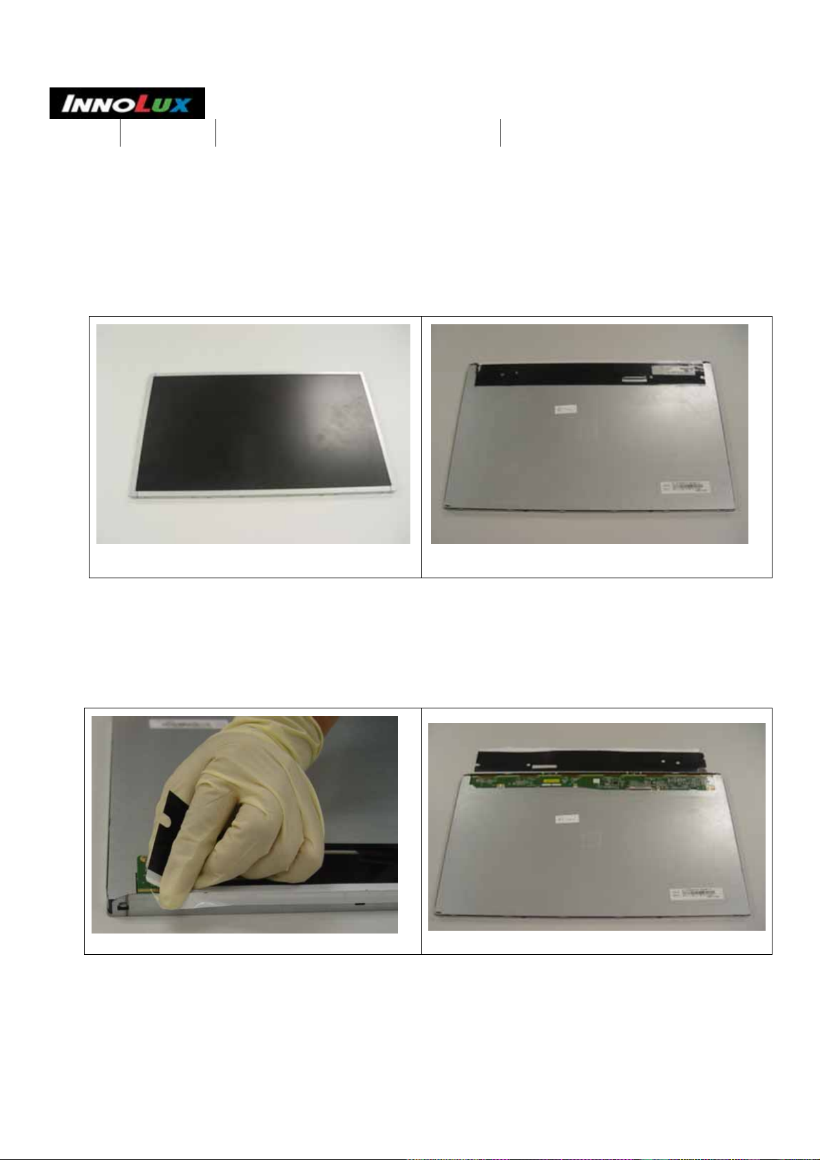
1. Original condition
A.6 Ecology of TCO' 03 頁 次 :
群 創 光 電 股 份 有 限 公 司
版本:V.2
11/16
1-1 the obverse side of the Module
1-2 the reverse side of the Module
2. Remove the protect cover (above PCBA)
2-1 pulling the protect cover
2-2 the protect cover removed
11
Page 4
廠商名稱
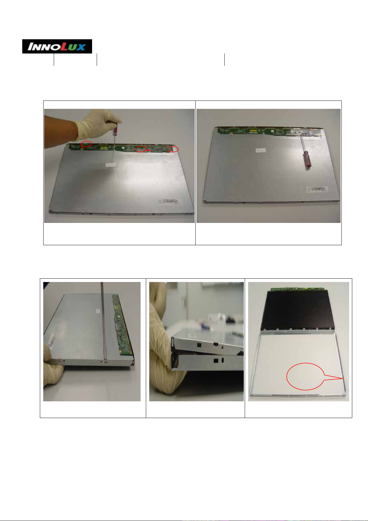
3.Remove the screw
A.6 Ecology of TCO' 03 頁 次 :
群 創 光 電 股 份 有 限 公 司
版本:V.2
12/16
3-1. remove the screws (there are three screws marked
in this picture.)
4. Remove Top Bezel
4-1 prizing the Bezel with a screw
driver.
4-2 prizing the Bezel softly with
hand.
3-2 The screws have removed.
Top
Bezel
4-3 Top Bezel removed
12
Page 5

廠商名稱
5. Remove LCD Cell &PCBA
5-1 remove the LCD Cell & PCBA softly. 5-2 the LCD Cell & PCBA removed
A.6 Ecology of TCO' 03 頁 次 :
群 創 光 電 股 份 有 限 公 司
版本:V.2
13/16
6. Remove Mold Frame (Plastic Frame)
6-1 prizing the Bezel with a screw driver.
6-2 remove the Frame with hand softly
13
Page 6

廠商名稱
A.6 Ecology of TCO' 03 頁 次 :
群 創 光 電 股 份 有 限 公 司
版本:V.2
14/16
6-3 remove the Frame w ith hand softly
7.Remove the Film
6-4 the Frame removed
7-1 remove the Film
7-2 the Film removed
14
Page 7

廠商名稱
8. Remove LGP
A.6 Ecology of TCO' 03 頁 次 :
群 創 光 電 股 份 有 限 公 司
版本:V.2
15/16
8-1 remove the LGP
9. Remove the Reflector
9-1 pull the Film softly
8-2 the LGP removed
The LED
9-2 the Film removed
15
Page 8

廠商名稱
10. Remove the LED
A.6 Ecology of TCO' 03 頁 次 :
群 創 光 電 股 份 有 限 公 司
版本:V.2
16/16
LED
10-1 prizing the LED with a screw driver and pull it softly
10-2 the LED separated
16
Page 9

g
Disassembly Flowchart for HP compaq LE19f Model
Issue Date:2009.10.27
Initiator:Michael Loon
Action Tool Photo
Lay the Monitor on the desk, Unlock the 3
screws which fix the stand with the screw
driver
Take out the bezel with hand. N/A
#1 Crossing Screw Driver
Take out the keypad PCBA with hand N/A
Unlock the 4screws which fix the back
cover and chassis,then take out the back
cover.
#1 Crossing Screw Driver
Unlock the 4 screws which fix the panel #1 Crossing Screw Driver
Page 10

Remove the light wire from Power PCBA. N/A
Remove the FFC connector from Panel. N/A
Chassis assembly and panel N/A
Remove the FFC wire from PCBA N/A
Unlock the 4 screws which fix the IF board
to the chassis,unlock the 2 screws which fix
power socket to the chassis
#2 Crossing Screw Driver
#1 Crossing Screw Driver
Page 11

Unlock the 2 screws which fix the IF PCBA #1 Crossing Screw Driver
Unlock the 5 screws which fix the power
board,then take out the wires.
Chassis N/A
Unlock the screw which fix the Hinge Cover
#1 Crossing Screw Driver
#1 Crossing Screw Driver
By pushing the rib of the base cover ,detach
Base Cover and Arm
Remove seven rubber foots and unlock four
screws which fix the Base Cover
N/A
#1 Crossing Screw Driver
Page 12

Remove the arm rear cover N/A
Unlock the four screws which fix the Arm
front
Unlock the 2 nuts which fix the shaft M6.0 spanner
#1 Crossing Screw Driver
 Loading...