


Fibre Channel SAN Switch 16
Installation and Hardware Guide
Second Edition (June 2000)
Part Number EK-BCP28-IA. B01 / 161356-002
Compaq Computer Corporation

ii Compaq StorageWorks Fibre Channel SAN Switch 16 Installation and Hardware Guide
Notice
© 2000 Compaq Computer Corporation
COMPAQ, the Compaq logo, and StorageWorks Registered in U. S. Patent and Trademark Office.
Microsoft, Windows 95, Windows 98, Windows NT, and Windows 2000 are registered trademarks of
Microsoft Corporation in the United States and/or other countries.
Intel is a registered trademark of Intel Corporation in the United States and/or other countries.
All other product names mentioned herein may be trademarks or registered trademarks of their
respective companies.
Compaq shall not be liable for technical or editorial errors or omissions contained herein. The
information in this document is subject to change without notice.
The information in this publication is subject to change without notice and is provided “AS IS”
WITHOUT WARRANTY OF ANY KIND. THE ENTIRE RISK ARISING OUT OF THE USE OF
THIS INFORMATION REMAINS WITH RECIPIENT. IN NO EVENT SHALL COMPAQ BE
LIABLE FOR ANY DIRECT, CONSEQUENTIAL, INCIDENTAL, SPECIAL, PUNITIVE, OR
OTHER DAMAGES WHATSOEVER (INCLUDING WITHOUT LIMITATION, DAMAGES FOR
LOSS OF BUSINESS PROFITS, BUSINESS INTERRUPTION, OR LOSS OF BUSINESS
INFORMATION), EVEN IF COMPAQ HAS BEEN ADVISED OF THE POSSIBILITY OF SUCH
DAMAGES. THE FOREGOING SHALL APPLY REGARDLESS OF THE NEGLIGENCE OR
OTHER FAULT OF EITHER PARTY AND REGARDLESS OF WHETHER SUCH LIABILITY
SOUNDS IN CONTRACT, NEGLIGENCE, TORT, OR ANY OTHER THEORY OF LEGAL
LIABILITY, AND NOTWITHSTANDING ANY FAILURE OF ESSENTIAL PURPOSE OF ANY
LIMITED REMEDY.
The limited warranties for Compaq products are exclusively set forth in the documentation
accompanying such products. Nothing herein should be construed as constituting a further or additional
warranty.
Printed in the U.S.A.
Compaq StorageWorks Fibre Channel SAN Switch 16 Installation and Hardware Guide
Second Edition (June 2000)
Part Number EK-BCP28-IA. B01 / 161356-002

Contents iii
Contents
About This Guide
Document Structure............................................................................................... ix
Related Documents.................................................................................................x
Text Conventions ................................................................................................. xii
Symbols in Text .................................................................................................. xiii
Symbols on Equipment......................................................................................... xii
Rack Stability...................................................................................................... xiv
Getting Help......................................................................................................... xv
Compaq Technical Support............................................................................ xv
Compaq Website ........................................................................................... xv
Compaq Authorized Reseller ........................................................................xvi
Chapter 1
Overview
Front Panel.......................................................................................................... 1-2
Features...............................................................................................................1-3
Performance........................................................................................................1-5
Manageability......................................................................................................1-5
Compatibility ......................................................................................................1-6
Reliability ...........................................................................................................1-6
Serviceability ......................................................................................................1-7
Switch Components.............................................................................................1-7
GBIC Modules .............................................................................................1-8
Switching Function.......................................................................................1-9
Chapter 2
Installing the Fibre Channel SAN Switch 16
Package Contents ................................................................................................ 2-2
Selecting an Operating Location ..........................................................................2-2
Cooling Requirements ..................................................................................2-2
Power Requirements..................................................................................... 2-3

iv Compaq StorageWorks Fibre Channel SAN Switch 16 Installation and Hardware Guide
Installing the Fibre Channel SAN Switch 16
continued
Selecting a Switch Mounting Method................................................................... 2-3
Surface Mounting......................................................................................... 2-3
Rack Mounting............................................................................................. 2-3
Installing GBIC Modules..................................................................................... 2-4
Cable Specification.............................................................................................. 2-4
Fibre Channel Cables.................................................................................... 2-4
Connecting the Storage System and Host ............................................................. 2-6
Connecting the Power Cable................................................................................ 2-7
Connecting the Ethernet Cable............................................................................. 2-7
Cascading Switches............................................................................................. 2-8
Chapter 3
Setting up the Fibre Channel SAN Switch 16
Powering Up the Switch ...................................................................................... 3-1
Front Panel LED Indicators...........................................................................3-2
Verifying the Power On Self-Test ................................................................. 3-2
Setting the IP Address...................................................................................3-3
Initiating a Terminal or Telnet Session................................................................. 3-4
Save and Restore Switch Configuration Settings.................................................. 3-5
configUpload................................................................................................3-5
configDownload ........................................................................................... 3-7
Chapter 4
Front Panel Switch Management
Control Buttons................................................................................................... 4-2
Activating the Menu Display ............................................................................... 4-3
Menus................................................................................................................. 4-3
Commands.......................................................................................................... 4-4

Contents v
Front Panel Switch Management
continued
Configuration Menu ............................................................................................4-7
Ethernet IP Address...................................................................................... 4-7
Ethernet Subnetmask .................................................................................... 4-7
Fibre Channel IP Address .............................................................................4-8
Fibre Channel Subnetmask............................................................................4-8
Gateway Address.......................................................................................... 4-8
Domain ........................................................................................................ 4-8
BB_credit..................................................................................................... 4-9
R ..................................................................................................................4-9
E_D_TOV.................................................................................................... 4-9
Data Field Size ........................................................................................... 4-10
Non-SCSI Tachyon Mode........................................................................... 4-10
Disable Device Probing .............................................................................. 4-10
VC-Encoded Address Mode........................................................................ 4-10
Per-Frame Route Priority............................................................................ 4-10
Virtual Channels......................................................................................... 4-11
VC Priorities...............................................................................................4-11
Disable Fan Frames ....................................................................................4-11
Always Send RSCN?.................................................................................. 4-11
Set QuickLoop Port ....................................................................................4-11
Unset QuickLoop Port ................................................................................ 4-12
QuickLoop Partner WWN...........................................................................4-12
QuickLoop No AL_PA 0x00.......................................................................4-12
Reset to Default.......................................................................................... 4-12
Operation Menu.................................................................................................4-12
Switch Offline ............................................................................................4-12
Switch Online............................................................................................. 4-13
Port Disable................................................................................................ 4-13
Port Enable................................................................................................. 4-13
QuickLoop Disable..................................................................................... 4-13
QuickLoop Enable...................................................................................... 4-13
QuickLoop Port Disable.............................................................................. 4-13
QuickLoop Port Enable...............................................................................4-14
Close Telnet Session................................................................................... 4-14
Reboot........................................................................................................ 4-14

vi Compaq StorageWorks Fibre Channel SAN Switch 16 Installation and Hardware Guide
Front Panel Switch Management
continued
Status Menu ...................................................................................................... 4-14
Switch Name.............................................................................................. 4-14
Worldwide Name........................................................................................4-14
Firmware Version....................................................................................... 4-15
Current Date............................................................................................... 4-15
Booted At................................................................................................... 4-15
Firmware Date............................................................................................ 4-15
Flash Date ..................................................................................................4-15
Boot Prom Date.......................................................................................... 4-15
Up Time ..................................................................................................... 4-16
Powered Time ............................................................................................4-16
Port Type.................................................................................................... 4-16
Module Type.............................................................................................. 4-17
Port Throughput .........................................................................................4-17
Temperature............................................................................................... 4-17
Error Log....................................................................................................4-17
Licenses..................................................................................................... 4-18
Test Menu......................................................................................................... 4-18
Chapter 5
Diagnostics
Overview ............................................................................................................5-1
Isolating a System Fault................................................................................ 5-1
Rebooting or Removing Power..................................................................... 5-2
POST ........................................................................................................... 5-2
Diagnostic Tests.................................................................................................. 5-2
Test Menu........................................................................................................... 5-3
Switch Offline ..............................................................................................5-4
Switch Online............................................................................................... 5-4
Memory Test................................................................................................ 5-4
Port Register Test ......................................................................................... 5-5
Central Memory Test.................................................................................... 5-5
CMI Conn Test............................................................................................. 5-5
CAM Test ....................................................................................................5-6
Port Loopback Test....................................................................................... 5-6
Cross Port Test............................................................................................. 5-6
Spin Silk Test............................................................................................... 5-7
SRAM Data Retention Test...........................................................................5-7
CMEM Data Retention Test.......................................................................... 5-7
Display Test .................................................................................................5-7
Display Test (long)....................................................................................... 5-7
Push Button Test ..........................................................................................5-8

Contents vii
Chapter 6
Error Messages
Switch Error Message Formats ............................................................................6-1
Front Panel Format .......................................................................................6-1
Telnet Format ...............................................................................................6-2
Diagnostic Error Message Formats.......................................................................6-3
Error Message Numbers ...................................................................................... 6-4
Error Message Tables ................................................................................... 6-9
Chapter 7
Repair and Replacement
Switch Configuration Settings..............................................................................7-2
Saving the Settings....................................................................................... 7-2
Restoring the Settings................................................................................... 7-2
Field Replaceable Units.......................................................................................7-3
Replacing the Power Supply ................................................................................7-3
Removing the Power Supply.........................................................................7-3
Installing the Power Supply ..........................................................................7-4
Replacing a GBIC Module................................................................................... 7-5
Removing a GBIC Module............................................................................ 7-5
Installing a GBIC Module ............................................................................. 7-6
Replacing the Fan Assembly................................................................................ 7-6
Removing the Fan Assembly......................................................................... 7-7
Installing the Fan Assembly.......................................................................... 7-7
Replacing the Motherboard.................................................................................. 7-8
Removing the Motherboard...........................................................................7-8
Installing the Motherboard ............................................................................7-9
Replacing the Chassis and Front Panel Assembly............................................... 7-10
Removing the Switch Components.............................................................. 7-10
Installing the Switch Components ............................................................... 7-10
Chapter 8
Upgrading Firmware
Upgrading Firmware Using Web Management Tools ...........................................8-2
Upgrading Firmware Using a Telnet Command.................................................... 8-3
Host with Windows NT Intel ........................................................................8-4
Host with Windows NT Alpha...................................................................... 8-5
Host with Tru64 UNIX................................................................................. 8-6
Downloading Firmware from the Compaq Website .............................................. 8-7

viii Compaq StorageWorks Fibre Channel SAN Switch 16 Installation and Hardware Guide
Appendix A
Regulatory Compliance Notices
Regulatory Compliance Identification Numbers.................................................. A-1
Federal Communications Commission Notice..................................................... A-1
Class A Equipment...................................................................................... A-2
Class B Equipment ......................................................................................A-2
Modifications.............................................................................................. A-3
Canadian Notice (Avis Canadien)....................................................................... A-4
Class A Equipment...................................................................................... A-4
Class B Equipment ......................................................................................A-4
European Union Notice ...................................................................................... A-4
Japanese Notice.................................................................................................. A-5
Taiwanese Notice............................................................................................... A-5
Laser Devices..................................................................................................... A-5
Laser Safety Warnings................................................................................. A-6
Compliance with CDRH Regulations........................................................... A-6
Compliance with International Regulations.................................................. A-6
Laser Product Label..................................................................................... A-7
Laser Information ........................................................................................ A-7
Appendix B
Electrostatic Discharge
Grounding Methods............................................................................................ B-2
Appendix C
Specifications
Switch Specifications ......................................................................................... C-2
Fabric Management Specifications...................................................................... C-2
Safety Specifications .......................................................................................... C-3
Optical Port Specifications.................................................................................. C-4
Environmental Specifications ............................................................................. C-4
Dimensions ........................................................................................................ C-5
Power Supply..................................................................................................... C-5
Index

About This Guide
This guide provides instructions for installing the Compaq StorageWorks
TM
Fibre Channel SAN Switch 16 and also includes information on operation,
troubleshooting, and future upgrades.
Document Structure
This guide contains the following information:
Chapter 1: Overview
Introduction of the front panel, features, performance, manageability,
compatibility, reliability, serviceability, and components.
Chapter 2: Installing the Fibre Channel SAN Switch 16
■ Package contents
■ Selecting an operating location, selecting a mounting method, installing
GBIC modules, and the cable specification.
■ Connecting to a storage system and host
■ Connecting the power cable and Ethernet cable
■ Cascading switches
Chapter 3: Setting up the Fibre Channel SAN Switch 16
Powering up the switch, making a serial connection, and initiating a Telnet
session.

x Compaq StorageWorks Fibre Channel SAN Switch 16 Installation and Hardware Guide
Chapter 4: Front Panel Switch Management
■ Control buttons
■ Activating the Menu Display
■ Menus, commands, configuration menu, operration menum, status
menu, and test menu.
Chapter 5: Diagnostics
Diagnostic overview, commands, and error messages.
Chapter 6: Error Messages
Switch error message formats, diagnostic error message format, and error
message numbers.
Chapter 7: Repair and Replacement
■ Save and restore configuration
■ Field replaceable units
■ Replacing the power supply, a GBIC module, the cover, the fan
assembly, the motherboard, and the chassis.
Chapter 8: Upgrading Firmware
Upgrading the firmware using Web Management Tools and Telnet commands.
Appendix A: Regulatory Compliance
Notices
FCC regulations
Appendix B: Electrostatic Discharge
Preventing damage to your product
Appendix C: Specifications
Switch specifications

Contents xi
Related Documents
In addition to this guide, the following documentation may be useful:
Table 2
Related Documents
Document Title Part Number
Compaq StorageWorksTM Fibre Channel SAN Switch 16 Release Notes
EK-P28FR-AA. C01
161365-003
Compaq StorageWorksTM Fibre Channel SAN Switch Management Guide AA-RMMJA-TE
207686-001
Compaq StorageWorksTM Command Console for Hubs, Switches, and
Tape Controllers Getting Started Guide
AA-RHDAC-TE
135265-003
Compaq StorageWorksTM SAN Switch Remote Switch Services
Installation Guide
EK-SANRS-AA. B01
165909-002

xii Compaq StorageWorks Fibre Channel SAN Switch 16 Installation and Hardware Guide
Text Conventions
This document uses the following conventions to distinguish elements of text:
Keys Keys on a keyboard appear in boldface.
<Keys>
Keys on the switch front panel appear in
hash marks (<>).
USER INPUT
User input appears in uppercase and different
typeface.
Filenames File names appear in initial capital letters italics.
Menu Options,
Command Names,
Dialog Box Names
These elements appear in initial capital letters.
COMMANDS,
DIRECTORY NAMES,
and DRIVE NAMES
These elements appear in uppercase.
Type When you are instructed to type information, type
the information without pressing the Enter key.
Enter
When you are instructed to enter information, type
the information and then press the Enter key.
Contents xiii
Symbols in Text
These symbols may be found in the text of this guide. They have the following
meanings.
WARNING: Text set off in this manner indicates that failure to follow directions
in the warning could result in bodily harm or loss of life.
CAUTION: Text set off in this manner indicates that failure to follow directions
could result in damage to equipment or loss of information.
IMPORTANT: Text set off in this manner presents clarifying information or specific
instructions.
NOTE: Text set off in this manner presents commentary, sidelights, or interesting points
of information.
Symbols on Equipment
These icons may be located on equipment in areas where hazardous conditions
may exist.
Any surface or area of the equipment marked with these symbols
indicates the presence of electric shock hazards. Enclosed area
contains no operator-serviceable parts.
WARNING: To reduce the risk of injury from electric shock hazards,
do not open this enclosure.
Any RJ-45 receptacle marked with these symbols indicates a Network
Interface Connection.
WARNING: To reduce the risk of electric shock, fire, or damage to the
equipment, do not plug telephone or telecommunications connectors
into this receptacle.
xiv Compaq StorageWorks Fibre Channel SAN Switch 16 Installation and Hardware Guide
Any surface or area of the equipment marked with these symbols
indicates the presence of a hot surface or hot component. If this
surface is contacted, the potential for injury exists.
WARNING: To reduce the risk of injury from a hot component, allow
the surface to cool before touching.
Power supplies or systems marked with these symbols indicate
the equipment is supplied by multiple sources of power.
WARNING: To reduce the risk of injury from electric shock,
remove all power cords to completely disconnect power from
the system.
Any product or assembly marked with these symbols indicates that
the component exceeds the recommended weight for one individual
to handle safely.
WARNING: To reduce the risk of personal injury or damage to the
equipment, observe local occupational health and safety
requirements and guidelines for manual material handling.
Rack Stability
WARNING: To reduce the risk of personal injury or damage to the equipment,
be sure that:
■ The leveling jacks are extended to the floor.
■ The full weight of the rack rests on the leveling jacks.
■ The stabilizing feet are attached to the rack if it is a single rack installation.
■ The racks are coupled in multiple rack installations.
■ A rack may become unstable if more than one component is extended for
any reason. Extend only one component at a time.

Contents xv
Getting Help
If you have a problem and have exhausted the information in this guide, you
can get further information and other help in the following locations.
Compaq Technical Support
In North America, call the Compaq Technical Phone Support Center at
1-800-OK-COMPAQ. This service is available 24 hours a day, 7 days a week.
For continuous quality improvement, calls may be recorded or monitored.
Outside North America, call the nearest Compaq Technical Support Phone
Center. Telephone numbers for worldwide Technical Support Centers are
listed on the Compaq website. Access the Compaq website at
http://www.compaq.com.
Be sure to have the following information available before you call Compaq:
■ Technical support registration number (if applicable)
■ Product serial number
■ Product model name and numbers
■ Applicable error messages
■ Add-on boards or hardware
■ Third-party hardware or software
■ Operating system type and revision level
Compaq Website
The Compaq website has information on this product as well as the latest
drivers and Flash ROM images. You can access the Compaq website at
http://www.compaq.com.

xvi Compaq StorageWorks Fibre Channel SAN Switch 16 Installation and Hardware Guide
Compaq Authorized Reseller
For the name of your nearest Compaq authorized reseller:
■ In the United States, call 1-800-345-1518.
■ In Canada, call 1-800-263-5868.
■ Elsewhere, see the Compaq website for locations and telephone
numbers.

Chapter 1
Overview
The Compaq StorageWorksTM Fibre Channel SAN Switch 16 is a 16-port Fibre
Channel switch that provides a flexible switching platform to meet both
low-latency and high-throughput demands. It consists of a motherboard with
connections for up to 16 Giga Bit Interface Converter (GBIC) modules, one or
two power supplies, a fan assembly, a chassis with an RJ-45 Ethernet
connection, and a front panel display with a keypad. The switch’s management
functions let you control and monitor fabric topology, frame throughput, error
statistics, fans, cooling, media type, port status, and a variety of other
information to aid in system debugging and performance analysis.
1-2 Compaq StorageWorks Fibre Channel SAN Switch 16 Installation and Hardware Guide
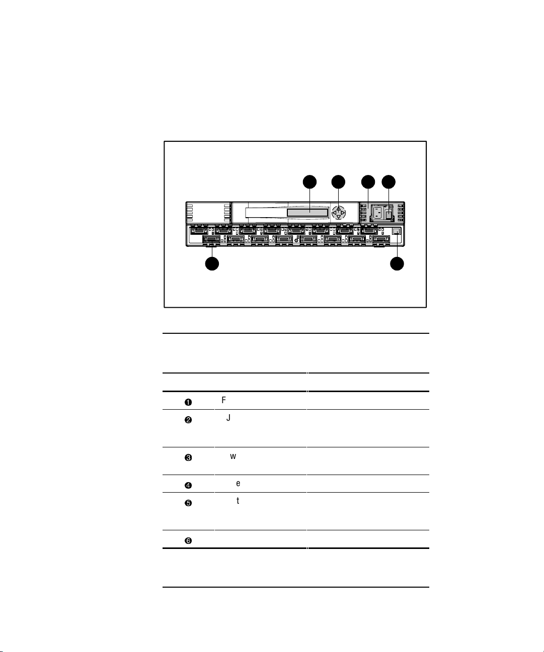
Front Panel
Figure 1-1 shows the front view of the Fibre Channel SAN Switch 16.
Table 1-1 describes the front panel features.
1 2
4356
Figure 1-1. Fibre Channel SAN Switch 16 front panel
Table 1-1
Front Panel Features
Identifier Description Function
1
Fibre Channel ports Connects the switch to devices
2
RJ-45 Ethernet
connector
Connects the switch to the
network for out-of-band
(Ethernet) management
3
Power supply Connects the switch to the
power source
4
Power ON/OFF switch Turns the unit on and off
5
Front panel controls Control navigation through
menus and let you increment
and decrement numeric values
6
Front panel display Displays switch information
NOTE: Fibre Channel ports are numbered sequentially starting with zero for
the far left port. The switch faceplate includes an imprint of each port
number.

Overview 1-3
Features
The Fibre Channel SAN Switch 16 has the following features:
■ Simplicity— The Fibre Channel SAN Switch 16 is easy to set up and
configure. After the Power On Self-Test (POST), add the switch’s
Internet protocol (IP) address. The remainder of the setup is automated.
■ Intelligence— The operating system allows discovery of all connected
devices and determines optimum data paths without intervention.
■ Flexibility— The GBIC modules support single-mode and multi-mode
fiber transmission media. The switch’s modular construction allows
flexibility in creating, upgrading, maintaining, and configuring a fabric.
■ Reliability— Highly integrated, reliable, multifunction Application
Specific Integrated Circuits (ASIC) devices are used throughout the
switch.
■ High performance— The low-latency, high-performance design
requires no processor data path interaction. The Fibre Channel
bandwidth is 100 megabytes per second (MB/s) per port (full duplex).
NOTE: The latency can differ when the device or destination is configured in a loop.
■ Automated congestion management— Virtual channels enable the
switch to perform sophisticated congestion management techniques
automatically.
■ Cascading— Switches can be cascaded for large fabric support.
Switches can be interconnected for a large fabric with multiple fabric
connections. .
■ Compatibility— The Fibre Channel SAN Switch 16 is designed to
operate with other Compaq StorageWorks Fibre Channel Switches using
a compatibility mode.
■ Universal Ports— Switch ports are designed to support F_, FL_, and
E_Port modes of operation. The software automatically selects the
optimum mode of operation.

1-4 Compaq StorageWorks Fibre Channel SAN Switch 16 Installation and Hardware Guide
Table 1-2 describes the switch’s technical features.
Table 1-2
Fibre Channel SAN Switch 16 Technical Features
Feature Description
Login (FC) Explicit fabric login is supported.
Data field size The Fibre Channel frame can be up to 2112 bytes in size. The number
of bytes must be a multiple of 4.
Buffering A total of 128 standard-size receive frame buffers are available for
each set of 4 Fibre Channel ports.
Adjustable
buffer-to-buffer
credit
Buffer-to-buffer credit for each F/FL_Port can be up to 31 credits. For
the E_Port, buffer-to-buffer credit can be a total of 31 credits
distributed among all 8 virtual channels.
In order frame
delivery
The switch delivers the frames to a destination F/FL_Port in the same
order received by the source F/FL_Port. The in-order frame delivery is
maintained within a fabric of multiple interconnected switches.
Automatic
address
assignment
Switch port address identifiers are selected using an automatic
address assignment protocol. All ports within a fabric are assigned
address identifiers. Each individual switch maintains its own address
pool for ports within the switch.
Hardware frame
routing
The switch implements hardware routing of frames between
communicating ports and supports self-routing of frames between
the communicating ports. The path selection in a multiswitch
configuration is based on a self-routing protocol.
User-defined
routing
The switch allows the configuration of user defined routes. Failed
paths are still used in the event of a failure.
Translative mode Translates 8-bit private loop addresses to 24-bit Phantom Public
Addresses to allow fabric-aware devices to access to private devices.
continued

Overview 1-5
Table 1-2
Fibre Channel SAN Switch 16 Technical Features
continued
Feature Description
Management The switch can be managed through the SNMP agent, Web
Management Tools, or Telnet included in the Compaq StorageWorks
TM
Command Console software. These items are accessible from the
Internet Protocol over the RJ-45 10/100BaseT Ethernet port or any
Fibre Channel port. You can use any SNMP-based management
product to access the SNMP agent and any supported Web browser
to use the Java Web Management Tools.
Name Server
The Name Server feature is based on the Simple Name Server model
defined in the Fibre Channel Standard. This function allows external
devices to discover other fabric-connected devices. Name Server
manages a database that relates external device quantities, including
mappings between N/NL_Port 24-bit Fibre Channel physical
addresses, World Wide Names (WWN), IP addresses, FC-4 device
types, and Initial Process Associators. External devices can register
and query this information using the Name Server function, which is
distributed across switches in a fabric.
Performance
A minimum aggregate routing capacity of 4,000,000 frames per second is
specified for Class 2, Class 3, and Class F frames. Non-blocking throughput of
up to 16 x 100 MB/s (1.6 gigabytes per second [GB/s]) is provided.
A maximum switch latency of less than two microseconds is specified for
Class 2, Class 3, and Class F frames when the output port is free.
Manageability
The Fibre Channel SAN Switch 16 can be managed in-band by using Fibre
Channel protocol, or out-of-band by connecting to the 10/100BaseT Ethernet
port. Management interfaces include SNMP, Web Management Tools, or
Telnet.

1-6 Compaq StorageWorks Fibre Channel SAN Switch 16 Installation and Hardware Guide
Compatibility
The Fibre Channel SAN Switch software (version 2.0 and above) is
compatible with the Fibre Channel Switch software (Version 1.6c or 1.6d),
allowing both types of switches to operate in the same fabric. To accomplish
this compatibility, the Fibre Channel SAN Switch 16 must be configured to
use a specific addressing mode. This mode is designated “VC Encoded
Address Mode.”
Invoke this mode using the
configure command, as described in Appendix A of
the Compaq StorageWorks
Fibre Channel SAN Switch Management Guide.
When using this compatibility mode, the maximum switch count in a fabric is
reduced from 239 to 32, and the maximum number of multicast groups is
reduced from 256 to 31.
If the compatibility mode is not set, the following error message displays when
you interconnect a Fibre Channel SAN Switch 16 and a Fibre Channel Switch:
FABRIC, SEGMENTED, LOG_WARNING
Description: Fabric segmented.
Probable Cause: Incompatible fabric parameters/switches or conflict zones.
Action: Reconfigure fabric or zones. See configure command.
Reliability
The following features ensure the switch’s reliability:
■ POST
■ BootROM Memory Testing
■ Temperature and fan-speed monitoring
■ Low component count
■ Optional dual-redundant hot-pluggable power supplies
Overview 1-7
Serviceability
The following features enhance the switch’s serviceability:
■ Simple enclosure
■ Loopback test modes for service
■ User-friendly diagnostics
■ No jumpers or switch settings
■ Error and significant event logging and reporting
■ Modular Field Replaceable Units
NOTE: For more information about field replaceable units (FRUs), see Chapter 7, “Repair
and Replacement.”
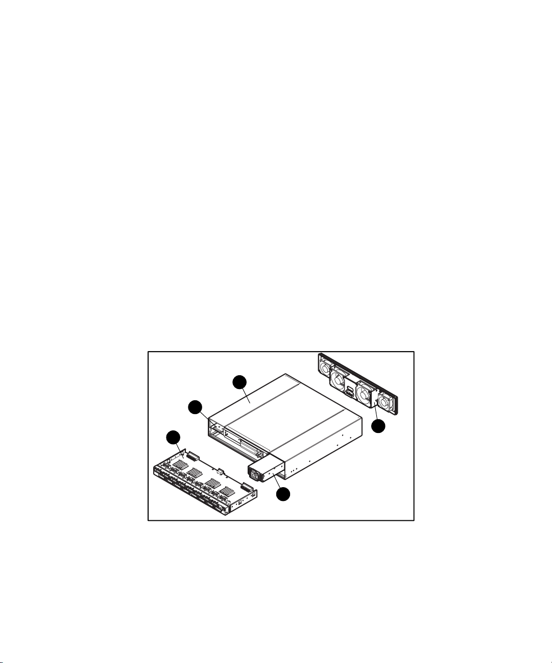
Switch Components
Figure 1-2 shows the top view of the Fibre Channel SAN Switch 16. Table 1-3
describes the key components.
3
5
2
1
4
Figure 1-2. Switch components
1-8 Compaq StorageWorks Fibre Channel SAN Switch 16 Installation and Hardware Guide
Table 1-3
Fibre Channel SAN Switch 16 Components
Identifier Description
1
Power supply
2
Dual power supply compartment or optional
redundant power supply
3
Motherboard
4
Fan assembly
5
Chassis
NOTE: The Fibre Channel SAN Switch 16 can support a dual-redundant
power supply configuration with hot-pluggable power supplies.
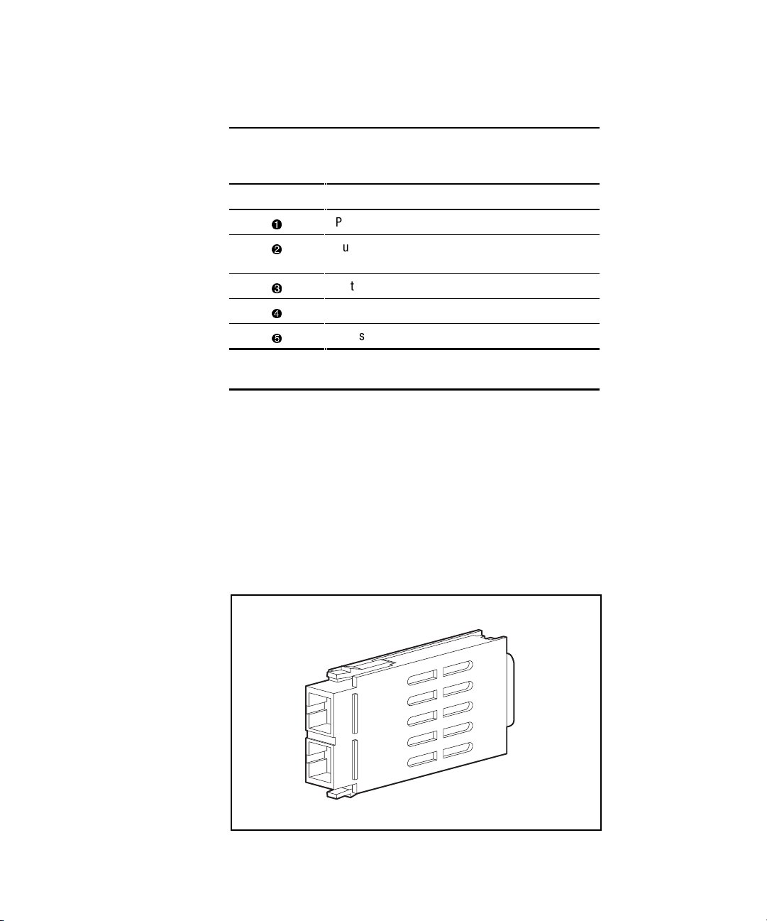
GBIC Modules
The Fibre Channel SAN Switch 16 accommodates up to sixteen
GBIC modules. All interfaces have status lights on the front panel for quick,
visual checks of the GBIC modules’ status and activity. If your installation
requires less than 16 GBIC modules, a metal, spring-loaded door protects the
unused port positions.
Shortwave (GBIC-SW) and longwave (GBIC-LW) GBIC modules are
supported. Figure 1-3 shows a GBIC module.
Figure 1-3. GBIC module

Overview 1-9
GBIC-SW Module
The GBIC-SW module with the subscriber connector (SC) color-coded black
is based on short wavelength 850 mm lasers supporting 1.0625 GB/s link
speeds. The GBIC-SW module supports 50-micron multi-mode fiber optic
cables in lengths up to 500 meters. The GBIC-SW module uses a Class 1 laser,
which complies with the 21 CFR, subpart (J) standard as of the date of
manufacture. The GBIC-SW module is shipped with a protective plug that
should remain in place when no fiber optic cable is connected to the port.
GBIC modules for the Fibre Channel SAN Switch 16 must be ordered
separately. The Compaq part number for the shortwave optical GBIC module
for multi-mode cable is 380561-B21.
GBIC-LW Module
The GBIC-LW module with the SC color-coded blue is based on long
wavelength 1300 mm lasers supporting 1.0625 GB/s link speeds. The
GBIC-LW module supports 9-micron single-mode fiber optic cables in lengths
up to 10 kilometers. The GBIC-LW module is shipped with a protective plug
that should remain in place when no fiber optic cable is connected to the port.
Two single-mode GBIC modules and a short single-mode test cable can be
ordered in a kit (part number 340412-B21).
In the Switch Management Application page of the Web Management Tools,
the GBICs are identified differently depending on the type of GBIC and the
supplier. Some examples of the displays include “ID” for VIXEL shortwave
GBICs and “SW” for IBM shortwave GBICs.
Switching Function
The Fibre Channel SAN Switch 16 switching function is based on a central
memory bank and its associated data path control. Each switch port stores
received frames in the central memory, while passing a buffer pointer to the
forwarding port’s transmitter. The switch uses cut-through routing to route
frames from the receiving port to the transmitting port, providing the
transmitting port is free, without waiting for the end of the frame to be
received. This provides a low-latency data path within the switch. If the
transmitting port is busy, the frame can be temporarily stored in the switch’s
memory bank.


Chapter 2
Installing the Fibre Channel SAN Switch
16
This chapter covers the following topics:
■ Package contents
■ Selecting an operating location
■ Selecting a switch mounting method
■ Installing GBIC modules
■ Cable specifications
■ Connecting the storage system and host
■ Connecting the power cable
■ Connecting the Ethernet cable
■ Cascading switches
2-2 Compaq StorageWorks Fibre Channel SAN Switch 16 Installation and Hardware Guide
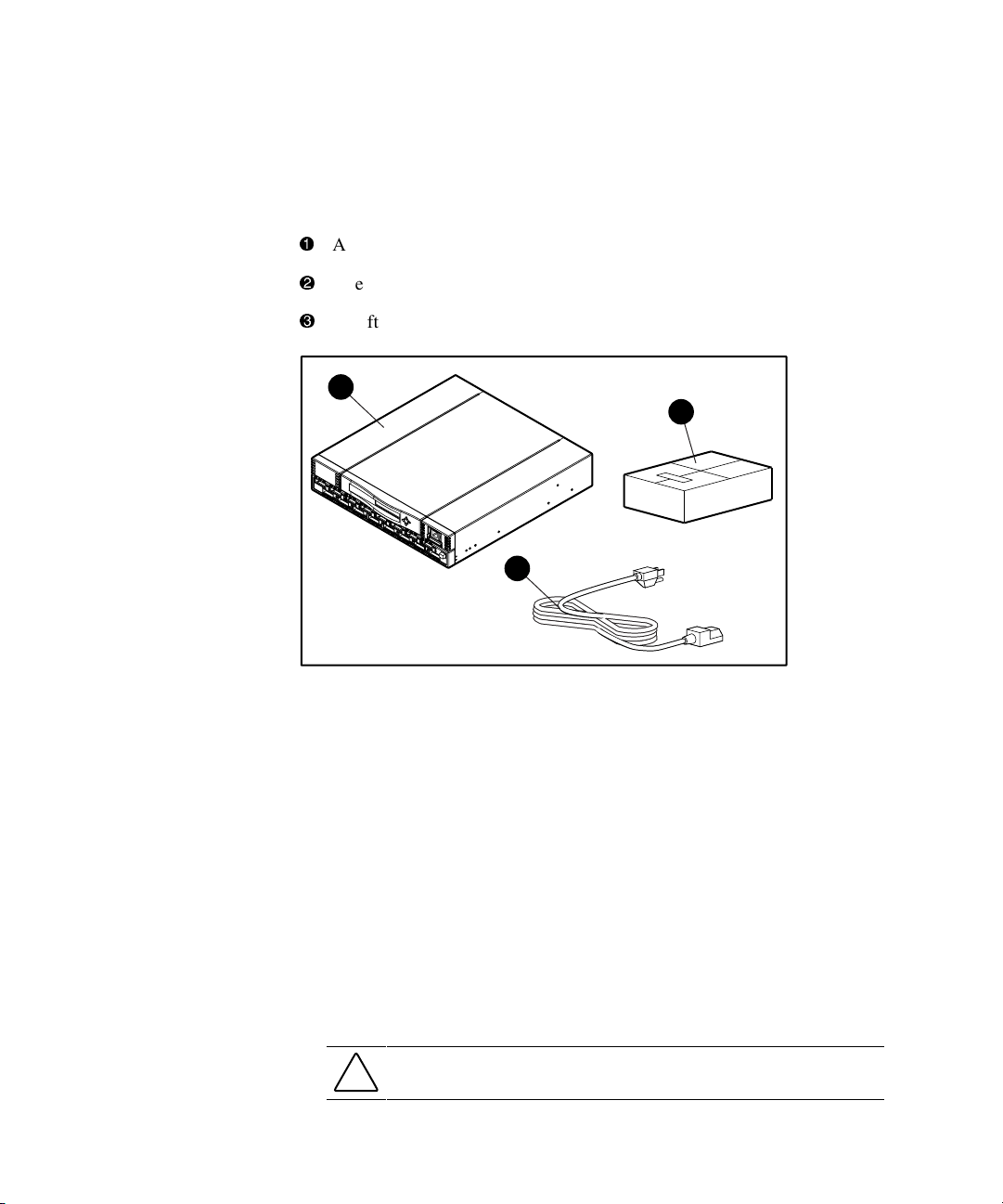
Package Contents
Make sure the following items are included in your kit:
1
A 16-port Fibre Channel Switch
2
One AC power cord
3
A software and documentation package
1
2
3
Figure 2-1. Switch kit contents
Selecting an Operating Location
The switch should be located in a secure or limited-access area to ensure that
cable connections are not compromised. The operating location you select for
the switch must meet the cooling air requirements and power requirements
described in the following sections.
Cooling Requirements
Cooling air is drawn into the switch chassis by four fans mounted near the rear
of the chassis. Exhausted air is expelled through vents in the front of the
chassis. The combined air flow through the switch is 75 cubic feet per minute
(cfm), with nominal bulk flow of 15 cfm.
CAUTION: Do not block the front or rear air vents. The switch uses ambient air
for cooling.

Installing the Fibre Channel SAN Switch 16 2-3
Power Requirements
The AC power cord is connected to the switch connector on the right side of
the switch front panel. If you have dual-redundant power supplies, the second
AC cord is connected to the switch connector on the left side of the switch
front panel. Each AC power sources must meet these requirements:
■ A properly wired, earth-grounded AC outlet
■ Voltage capability of 85-265 VAC
■ Input voltage frequency of 47-63 Hz
■ Power capability of 150 watts, maximum
The switch has an auto-ranging power supply that automatically accepts
voltages within its range. There is no provision for surge protection built into
the switch power supply, so the AC source should include provisions to ensure
clean AC power.
Selecting a Switch Mounting Method
The switch can be placed on a flat surface, such as a tabletop, or mounted in an
optional, standard 19-inch equipment rack with an optional rack mounting kit,
part number 167365-B21.
Surface Mounting
To operate the switch on a surface, place the four rubber feet, provided in the
kit, on the bottom surface of the switch. Continue the installation procedure
with “Installing GBIC Modules,” later in this chapter.
Rack Mounting
You can install the switch in a RETMA 42U rack, in a Compaq rack, or in a
metric SW600 rack. Refer to the documentation that came in your
rack-mounting option kit for more information.

2-4 Compaq StorageWorks Fibre Channel SAN Switch 16 Installation and Hardware Guide
Installing GBIC Modules
The switch can accommodate up to 16 GBIC modules. GBIC modules are
hot-pluggable. To install a GBIC module:
CAUTION: The GBIC modules contain static-sensitive components. Use
electrostatic discharge (ESD) precautions while handling GBIC modules.
1. Insert a GBIC module into a Fibre Channel port. The module is keyed
and can only be inserted one way.
CAUTION: Do not force the GBIC module into a port if you feel resistance.
2. Fully insert the GBIC module until it is properly seated in the
Fibre Channel port. If you are using a GBIC module with a locking bar,
lock the module in place with the locking bar. For other GBIC modules,
the latch prongs automatically lock to prevent accidental removal of the
GBIC module.
3. Insert a protective plug over the GBIC module’s fiber-optic connectors.
4. Repeat the procedure for each GBIC module to be installed.
Cable Specification
All cables connect at the front of the switch.
Fibre Channel Cables
Optical cables for the switch must be ordered separately. 500 meters or less
cables should be multi-mode Fibre Channel cables. Cables that are longer than
500 meters should be single-mode. Multi-mode optical cables are connected to
shortwave GBIC modules in the switch. Single-mode optical cables are
connected to longwave GBIC modules in the switch. Multi-mode cables
should use 50/125 optical fibers, SC Duplex connectors with a PC finish. Use
of 62.5/125 should be restricted to situations where 62.5/125 optical fiber was
previously installed and the link lengths are to be kept shorter than 200 meters.
Single-mode cables typically use 9/125 optical fibers for distances up to
10 km.
Table 2-1 lists the cable specifications for Fibre Channel cables.

Installing the Fibre Channel SAN Switch 16 2-5
Table 2-1
Fibre Channel Cabling Specifications
Cable Type Cable Specifications Maximum Length GBIC Module
Shortwave
Fiber Optic
■ Duplex SC plug connectors
■ Multi-mode fiber
■ 50 µm core diameter
■ 125 µm cladding diameter
duplex cable
1,641 ft (500 m)
780-860
µm
without open
fiber control
(non-OFC)
Longwave
Fiber Optic
■ Duplex SC plug connectors
■ Single-mode fiber
■ 9 µm core diameter
■ 125 µm cladding diameter
duplex cable
84,480 ft (10 km)
1270-1350
µm
without open
fiber control
(non-OFC)

2-6 Compaq StorageWorks Fibre Channel SAN Switch 16 Installation and Hardware Guide
Connecting the Storage System and Host
The storage system and host devices connect to the GBIC modules in the
switch’s Fibre Channel ports. Cable connectors are keyed and must be inserted
properly into the GBIC module connectors. Remove the protective cover from
the GBIC connector and make sure that the surfaces of all cable and
GBIC module connectors are clean and free of dust and debris. Figure 2-2
shows the cable connections.
Figure 2-2. Connecting a cable to a GBIC module in a Fibre Channel port

Installing the Fibre Channel SAN Switch 16 2-7
Connecting the Power Cable
Connect the AC power cable to the AC connector on the front, right side of the
switch. If you have dual-redundant power supplies, connect the second power
cable to the AC connectors on the front, left side of the switch.
Figure 2-3. Connecting the power cable

2-8 Compaq StorageWorks Fibre Channel SAN Switch 16 Installation and Hardware Guide
Connecting the Ethernet Cable
Connect the switch to an Ethernet 10/100BaseT network by plugging in the
Ethernet cable at the RJ-45 connector. This connection allows access to the
switch’s internal SNMP agent and remote Telnet and Web access.
Figure 2-4. Connecting the Ethernet cable
Cascading Switches
The switch supports cascading of switches. See the Compaq Solutions Kits for
supported configurations involving cascading of switches.
The domain ID number uniquely identifies a switch in a fabric. Normally, the
switch automatically assigns the domain ID when a switch is first powered on
or when the switch disable/enable command is executed. When two switches
are cascaded together, there might be an initial domain ID conflict if the
switches had been assigned the same domain ID prior to being cascaded. This
can be avoided by changing the domain ID with the configure command, by
disabling and enabling one of the switches, or rebooting one of the switches.
Refer to the Compaq StorageWorks Fibre Channel SAN Switch Management
Guide for more information.

Chapter 3
Setting up the Fibre Channel
SAN Switch 16
This chapter covers the following topics:
■ Powering up the switch
q
Front panel LED indicators
q
Verifying the POST
q
Setting the IP address
■ Initiating a Terminal or Telnet session
■ Save and restore switch configuration settings
Powering Up the Switch
Turn on the AC power switch located on each power supply. The switch
automatically runs the POST and the LED indicators become active.

3-2 Compaq StorageWorks Fibre Channel SAN Switch 16 Installation and Hardware Guide
Front Panel LED Indicators
The color and flash speed of the front panel indicators shows the status of each
Fibre Channel port. Table 3-1 contains descriptions of the port status
indicators.
Table 3-1
Port Status Indicators
LED Indicators Definition
No light showing No light or signal carrier (no GBIC module or cable installed) for
media interface indicator.
Steady amber Receiving light or signal carrier, but not online yet.
Slow flashing amber Disabled, flashes every 2 seconds.
Fast flashing amber Error or fault with port, flashes every half second.
Steady green Online (connected to device over cable).
Slow flashing green Online but cannot make a proper fabric connection (loopback
cable is installed, fabric is segmented, or switch is connected to
an incompatible switch), flashes every 2 seconds.
Fast flashing green Internal loopback (diagnostic), flashes every half second.
Flickering green The port is active and transferring data and frame traffic.
Alternating green
and amber
The port is bypassed.
Verifying the Power On Self-Test
The switch employs POST to determine operating status and isolate problems.
When a test completes successfully, the message “Passed” displays on the
front panel display.
If the POST is completed successfully, the switch is ready to operate. Should
the switch fail to complete POST successfully, the green power LED indicator
on the front panel next to the RJ-45 Ethernet connector will flash. This
indicates a fault in one of the initial stages of POST and signifies that the
processor is unable to bring up the operating environment. If this error occurs,
the switch could require repair.
If the switch’s operating system completely boots but other errors are
encountered during POST, those errors are logged in the system error log. Use
a Telnet session to view the error log.

Setting up the Fibre Channel SAN Switch 16 3-3
NOTE: Error messages are stored in RAM and are lost when the switch is rebooted or
power is removed from the switch. View the error log messages before rebooting or
removing power from the switch. You can view the error log by issuing either the errShow
or errDump command. When all data-transferring processes external to the switch are
complete, removing power from the switch does not disrupt the fabric.
Refer to the Compaq StorageWorks
Fibre Channel SAN Switch Management Guide for
more information on these Telnet commands.
Setting the IP Address
The switch is configured with default IP address 10.77.77.77. This IP address
is used to establish a network connection to the switch through the external
Ethernet connection. To set a compatible network address before connecting
the switch to the network, change the IP address through the front panel
controls.
To set the IP address using the front panel controls:
1. Select the Configuration menu using the right front panel button.
2. Scroll down to the Ethernet IP Address option. Select this option using
the right button.
3. Use the Up and Down buttons to change the IP address value. Use the
left front panel button to move to the next set of values.
4. When all values are set, press the right button to finish.
5. Confirm that the IP address is correct and select Yes to store the address
in flash memory.
NOTE: To be completely accessible on the network, the switch can require netmask and
gateway addresses. See your network administrator to determine if additional addresses
are necessary. These addresses can also be set through options on the Configuration
menu.

3-4 Compaq StorageWorks Fibre Channel SAN Switch 16 Installation and Hardware Guide
Initiating a Terminal or Telnet Session
A Telnet session is initiated through an Ethernet connection between a
management station on the network and the switch Ethernet RJ-45 connector.
Through a Telnet session, you can manage the switch, perform diagnostics,
and view error messages. To initiate a Telnet session:
1. Launch Telnet from a workstation connected to the network.
NOTE: For Windows 95/Windows 98/Windows 2000/Windows NT, select Run from the
Start menu. Type Telnet, then click OK.
2. From Telnet, use the IP address to connect to the switch.
NOTE: For Windows 95/Windows 98/Windows 2000/Windows NT, select Remote System
from the Connect menu on the Telnet window. Enter the IP address of the switch in the
Host Name box.
3. Press Enter to display the login prompt. At the prompt, enter “admin.”
4. At the password prompt, enter “password.”
5. When the prompt switchName:userName> displays, enter a Telnet
command. You can change the password by using the passwd command.
During a Telnet session from a Tru64 UNIX or OpenVMS machine, the
Backspace, Delete, and Left Arrow keys do not work properly. The
keyboards shipped with these machines produce a “question mark” character
instead of deleting characters when using the Backspace key. It is necessary to
type Control + H to delete characters. The Delete key changes the case of the
letter at the cursor and prevents you from adding anything to the line. The Left
Arrow key deletes the character to its left and prevents you from adding
anything to the line.
Enter the Telnet command “backSpace 1” to allow the Delete key to work on
UNIX and OpenVMS machines.
For more information on the backSpace Telnet command and managing the
switch remotely, refer to the Compaq StorageWorks Fibre Channel SAN
Switch Management Guide that came with your switch.

Setting up the Fibre Channel SAN Switch 16 3-5
Save and Restore Switch Configuration
Settings
Configuration settings can be lost upon switch failure. It is recommended that
you save your switch configuration settings using the configUpload Telnet
command. In order to restore your saved configuration settings, use the
configDownload Telnet command.
configUpload
This command saves the switch configuration to a host file. The upload
process uses either FTP (File Transfer Protocol) or the RSHD protocol (TCP
service 514). Both of these services are widely available on Unix hosts, but
less so on Windows hosts.
On Microsoft Windows NT, the FTP server may have to be installed from the
distribution media and enabled, or on Windows NT or Microsoft Windows 9x
there are several good freeware and shareware FTP servers available.
The two utilities supplied for RSHD, Rshd.exe and Cat.exe, currently do not
support uploads, only downloads. Therefore, in a Windows environment, FTP
must be used and the FTP server must be running before an upload can occur.
The command may be invoked without any parameters, in which case the user
is prompted for input, including choice or FTP or RSHD. If invoked with three
parameters RSHD is used, otherwise presence of the fourth parameter (FTP
password) selects FTP.
Figure 3-1 shows a generic example of the configUpload command.
switch:admin>configUpload
Server Name or IP Address [host]:
IP Address for Server:
User Name [user]:
File Name [config.txt]:
Protocol (RSHD or FTP) [rshd]:
Figure 3-1. configUpload command example 1

3-6 Compaq StorageWorks Fibre Channel SAN Switch 16 Installation and Hardware Guide
If the upload fails, it is due to one of the following reasons:
■ The switch does not recognize the host name.
■ The host IP address can’t be contacted.
■ The user doesn’t have permission on the host.
■ The user runs a script that prints something at login.
■ The RSHD or FTP server is not running on the host.
The configuration file contains two types of lines, comments and name:value
pairs. Comments are written with "[" as the first character of the line (when
read back using configDownload, a line beginning with any punctuation
character is treated as a comment).
Table 3-2
Syntax of a Name:Value Pair
Name Value Pair
line whitespace name whitespace ":" whitespace value
name component {"." component}
whitespace {" " | " "}
component {"a"-"z" | "A"-"Z" | "0"-"9" | "_" | "-"}
value {<any character not including "
NOTE: Elements enclosed in curly braces ({...}) indicate zero or more
occurrences of the enclosed elements.
The configuration file is written as three sections. The first section contains the
switch boot parameters (otherwise known as the switch’s identity). It has
variables such as the switch’s name and IP address. This section corresponds to
the first few lines of output of the configShow command.
The second section contains general switch configuration variables, such as
diagnostic settings, fabric configuration settings, and SNMP settings. This
section corresponds to the output of the configShow command (after the first
few lines), although there are more lines uploaded than shown by the
command.
The third section contains the zoning configuration. It corresponds to the
output of the cfgShow command.

Setting up the Fibre Channel SAN Switch 16 3-7
Parameters
■ host— A host name or IP address in quotes, for example "citadel" or
"192.168.1.48." The configuration file is uploaded to this host.
■ user— A user name in quotes, for example "jdoe." This user name is
used to gain access to the host.
■ file— A file name in quotes, for example "config.txt." Absolute path
names may be specified using forward slash "/". Relative path names
create the file in the user's home directory on Unix hosts and in the
directory where the FTP server is running on Windows hosts.
■ passwd— If present, selects FTP.
switch:admin>configUpload
“citadel”,“jdoe”,“config.txt”,“passwd”
upload complete
Figure 3-2. configUpload command example 2
configDownload
The download process uses either FTP (File Transfer Protocol) or the RSHD
protocol (TCP service 514) to download a previously saved configuration file
from a host system into the switch. Both of these services are widely available
on Unix hosts, but less so on Windows hosts. See the Telnet
configUpload
command for a description of the configuration file format.
On Windows NT, the FTP server may have to be installed from the
distribution media and enabled. There are several good freeware and
shareware FTP servers available for Windows NT, Windows 9x, and
Windows 2000.
To use RSHD on Windows NT, Windows 9x, or Windows 2000, two utilities
are supplied, Rshd.exe and Cat.exe. The FTP server or RSHD must be running
before a download can occur.
The command may be invoked without any parameters, in which case the user
is prompted for input, including choice or FTP or RSHD. If invoked with three
parameters RSHD is used, otherwise presence of the fourth parameter (FTP
password) selects FTP. Figure 3-3 shows a generic example of the
configDownload command.

3-8 Compaq StorageWorks Fibre Channel SAN Switch 16 Installation and Hardware Guide
switch:admin>configDownload
Server Name or IP Address [host]:
IP Address for Server:
IP Address for Server:
IP Address for Server:
User Name [user]:
File Name [config.txt]:
Protocol (RSHD or FTP) [rshd]:
Figure 3-3. configDownload command example 1
If the download fails, it is due to one of the following reasons:
■ The switch does not recognize the host name.
■ The host IP address can’t be contacted.
■ The user doesn’t have permission on the host.
■ The user runs a script that prints something at login.
■ The file doesn’t exist on the host.
■ The file is not a switch configuration file.
■ The RSHD or FTP server is not running on the host.
■ The configuration data contains errors.
NOTE: The switch’s identity cannot be changed by configDownload. Parameters such as
the switch’s name and IP address are ignored. They are the lines in the configuration file,
which begin "boot."
NOTE: A licenseKey is only accepted if the boot.mac line matches the WorldWide Name
of the switch performing the download, otherwise it is ignored.
The download process is additive, for example, the lines read from the file are
added to the current switch configuration. It is therefore possible to change a
single configuration variable by downloading a file with a single line. All
other variables remain unchanged.
This is particularly important to understand when downloading a zoning
configuration. Since the new zoning information is added to the current
configuration there may not be any conflicts. If the current zoning
configuration is to be replaced, then the key word "clear:" may be inserted into
the configuration file immediately before the zoning lines.

Setting up the Fibre Channel SAN Switch 16 3-9
Parameters
■ host— A host name or IP address in quotes, for example "citadel" or
"192.168.1.48." The configuration file is downloaded from this host.
■ user— A user name in quotes, for example "jdoe." This user name is
used to gain access to the host.
■ file— A file name in quotes, for example "config.txt." Absolute path
names may be specified using forward slash "/". Relative path names
look for the file in the user's home directory on Unix hosts and in the
directory where the FTP or RSHD server is running on Windows hosts.
■ passwd— If present, selects FTP.
switch:admin>configDownload
“ citadel” ,“jdoe” ,“config.txt”
Committing configuration… done.
download complete
Figure 3-4. configDownload command example 2


Chapter 4
Front Panel Switch Management
This chapters covers the following topics:
■ Control buttons
■ Activating the menu display
■ Menus
■ Commands
■ Configuration menu
■ Operation menu
■ Status menu
■ Test menus

4-2 Compaq StorageWorks Fibre Channel SAN Switch 16 Installation and Hardware Guide
Control Buttons
Figure 4-1 shows the front panel buttons. Table 4-1 lists the primary control
button functions. The function of a button changes depending on the menu
level. Buttons either control navigation through the menus or increment and
decrement numeric values.
4
3
1
2
Figure 4-1. Front panel functionality
Table 4-1
Control Buttons
Identifier Description Function
1
Up
Scrolls down the command list and
increments numeric values.
2
Down
Scrolls up the command list and
decrements numeric values.
3
Enter
Accepts input and executes a selected
function.
4
Tab/Esc Tabs through options and reverses
through previous commands.
When entering a number, the <Up> and <Down> buttons start in the slow
mode and change to the fast mode if either button is held down. For a large
number, it may be faster to use the <Down> button.

Front Panel Switch Management 4-3
Activating the Menu Display
The switch’s front panel display is not normally illuminated. Pressing the front
panel buttons activates the display. If no command is issued within
30 seconds, the display turns off.
Menus
The following menus are controlled using the front panel buttons:
Table 4-2
Menu Hierarchy
Configuration Menu Operation Menu Status Menu Test Menu
Ethernet IP Address Switch Offline Switch Name Switch Offline
Ethernet Subnetmask Switch Online Worldwide
Name
Switch Online
Fibre Channel IP Address Port Disable Firmware
Version
Memory Test
Fibre Channel Subnetmask Port Enable Current Date Port Register Test
Gateway Address QuickLoop Disable Booted At Central Memory Test
Domain QuickLoop Enable Firmware Date Control Message
Interface (CMI) Conn
Test
BB_credit QuickLoop Port Disable Flash Date
Content Addressable
Memories (CAM) Test
R_A_TOV QuickLoop Port Enable Boot Prom Date Port Loopback Test
E_D_TOV Close Telnet Session Up Time Cross Port Test
Data Field Size Reboot Powered Time Spin Silk Test
Non-SCSI Tachyon Mode PortType
SRAM Data Retention
Test
Disable Device Probing Module Type
CMEM Data Retention
Test
VC Encoded Address Mode Port Throughput Display Test
Per-Frame Route Priority Temperature Display Test (long)
continued

4-4 Compaq StorageWorks Fibre Channel SAN Switch 16 Installation and Hardware Guide
Table 4-2
Menu Hierarchy
continued
Configuration Menu Operation Menu Status Menu Test Menu
VC Priorities Error Log Push Button Test
Disable Fan Frames Licenses
Always Send RSCN?
Set QuickLoop Port
Unset QuickLoop Port
QuickLoop Partner WWN
QuickLoop No AL_PA OxOO
Reset to Default
Commands
Table 4-3 shows the front panel commands and their equivalent Telnet
commands.
Table 4-3
Front Panel and Telnet Commands
Menu Front Panel Telnet Command Default
Configuration Ethernet IP Address ipAddrSet 10.77.77.77
Ethernet Submask ipAddrSet none
Fibre Channel IP Address ipAddrSet none
Fibre Channel Subnetmask ipAddrSet none
Gateway Address ipAddrSet none
Domain configure 0
BB_credit configure 16 (G_Port) - 0 (FL_Port)
R_A_TOV configure 10000
E_D_TOV configure 2000
Data Field Size configure 2112
continued

Front Panel Switch Management 4-5
Table 4-3
Front Panel and Telnet Commands
continued
Menu Front Panel Telnet Command Default
Configuration Non-SCSI Tachyon Mode configure 0
Disable Device Probing configure 0
VC-Encoded Address Mode configure 0
Per-Frame Route Priority configure 0
VC Priorities configure 0,1,2,2,2,2,3,3
Disable Fan Frames configure 0
Always Send RSCN? configure 0
Set QuickLoop Port qlPortEnable <port #> 0
Unset QuickLoop Port qlPortDisable <port #> 0
QuickLoop Partner WWN qlPartner 00:00:00:00:00:00:00:00
QuickLoop No AL_PA OxOO configure 0
Reset to Default configDefault N/A
Operation Switch Offline switchDisable N/A
Switch Online switchEnable N/A
Port Disable portDisable <port #> N/A
Port Enable portEnable <port #> N/A
QuickLoop Disable qlDisable N/A
QuickLoop Enable qlEnable N/A
QuickLoop Port Disable qlPort Disable N/A
QuickLoop Port Enable qlPort Enable N/A
Close Telnet Session logout N/A
Reboot reboot N/A
continued

4-6 Compaq StorageWorks Fibre Channel SAN Switch 16 Installation and Hardware Guide
Table 4-3
Front Panel and Telnet Commands
continued
Menu Front Panel Telnet Command Default
Status Switch Name switchName N/A
Worldwide Name switchShow N/A
Firmware Version version N/A
Current Date date N/A
Booted At version N/A
Firmware Date version N/A
Flash Date version N/A
Boot Prom Date version N/A
Up Time uptime N/A
Powered Time uptime N/A
Port Type switchShow N/A
Module Type switchShow N/A
Port Throughput portPerfShow N/A
Temperature tempShow N/A
Error Log errShow N/A
Licenses licenseShow N/A
Test Switch Offline switchDisable N/A
Switch Online switchEnable N/A
Memory Test ramTest N/A
Port Register Test portRegTest N/A
Central Memory Test centralMemoryTest N/A
CMI Conn Test cmiTest N/A
CAM Test camTest N/A
Port Loopback Test portLoopbackTest N/A
Cross Port Test crossPortTest N/A
Spin Silk Test spinSilk N/A
continued

Front Panel Switch Management 4-7
Table 4-3
Front Panel and Telnet Commands
continued
Menu Front Panel Telnet Command Default
Test SRAM Data Retention Test sramRetention Test N/A
CMEM Data Retention Test cmemRetentionTest N/A
Display Test N/A N/A
Display Test (long) N/A N/A
Push-Button Test N/A N/A
Configuration Menu
Configure the switch using the Configuration menu. To choose commands,
press <Enter> while
Configuration Menu displays on the front panel.
NOTE: After changing any of the following menus from the front panel or a Telnet
connection, you must reboot the switch for the changes to take effect.
Ethernet IP Address
To view the switch’s Ethernet IP address, press <Enter> while Ethernet IP
Address
displays on the front panel. The switch’s default IP address is a
temporary address. To enter a new IP address:
1. Use <Up> and <Down> to increment or decrement the displayed value.
The underlined cursor indicates the numbers to modify.
2. After you enter a number, press <Tab/Esc> to modify the next field.
3. After setting the IP address, press <Enter> to store the value.
Ethernet Subnetmask
To view the Ethernet subnet mask value, press <Enter> while Ethernet
Subnetmask
displays on the front panel. To enter a new subnet address, use
<Up> and <Down> to increment or decrement the value. See your network
administrator for the appropriate subnet mask.

4-8 Compaq StorageWorks Fibre Channel SAN Switch 16 Installation and Hardware Guide
Fibre Channel IP Address
To view the switch’s Fibre Channel IP address, press <Enter> while Fibre
Channel IP Address
displays on the front panel. To change the Fibre Channel
IP address:
1. Use <Up> and <Down> to increment or decrement the displayed value.
2. After you enter a number, press <Tab/Esc> to modify the next field.
3. After setting the Fibre Channel IP address, press <Enter> to store the
value.
Fibre Channel Subnetmask
To view the Fibre Channel subnet mask, press <Enter> while Fibre Channel
Subnetmask
displays on the front panel. To enter a new subnet mask, use <Up>
and <Down> to increment or decrement the value. See your network
administrator for the appropriate subnetmask.
Gateway Address
To view the gateway address, press <Enter> while Gateway address displays on
the front panel. To enter a new gateway address:
1. Use <Up> and <Down> to increment or decrement the value.
2. After you enter a number, press <Tab/Esc> to move the cursor and
modify the next field.
3. After setting the gateway address, press <Enter> to store the value.
Domain
To view the domain number, press <Enter> while Domain displays on the front
panel. The domain number uniquely identifies each switch in a fabric. The
domain number can be any value between 1 and 239. If VC-Encoded Address
Mode is in effect, the value can by any number between 0 and 31. Normally,
the switch assigns itself a domain, but you can also assign this number
manually.

Front Panel Switch Management 4-9
BB_credit
To view the buffer-to-buffer credit, press <Enter> while BB_credit displays on
the front panel. The number that displays represents the number of buffers,
from 1 to 16, available to the host.
R_A_TOV
To view the Resource Allocation Time Out Value, press <Enter> while
R_A_TOV displays on the front panel. You can adjust this value in 1-second
increments using front panel controls, but it displays in milliseconds.
NOTE: Use the flashSet command during a Telnet session to set the R_A_TOV value for
values other than whole seconds.
R_A_TOV works with the Error Detect Time Out Value (E_D_TOV) to
determine the switch’s actions when presented with an error condition.
Allocated circuit resources with detected errors are not released until the time
value has expired. If the condition is resolved prior to timing out, the internal
time out clock resets. The R_A_TOV value can range from 1 to 120 seconds.
NOTE: The set value for R_A_TOV must be larger than the set value for E_D_TOV.
E_D_TOV
To view the Error Detect Time Out Value, press <Enter> while E_D_TOV
displays on the front panel. You can adjust this value in 1-second increments
using the front panel controls, but it displays in milliseconds.
NOTE: Use the flashSet command during a Telnet session to set the E_D_TOV value for
values other than whole seconds.
The E_D_TOV flags a potential error condition when an expected response is
not received (for example, an acknowledgment or reply in response to packet
receipt) within the set time limit. If the time for an expected response exceeds
the set value, an error condition results. The E_D_TOV value can range from
1 to 60 seconds.
NOTE: The set value for E_D_TOV must be smaller than the set value for the R_A_TOV.

4-10 Compaq StorageWorks Fibre Channel SAN Switch 16 Installation and Hardware Guide
Data Field Size
To view the data field size, press <Enter> while Data Field Size displays on the
front panel. You can adjust this value using the front panel controls. The data
field size specifies the largest possible value, in bytes, for the size of a type 1
(data) frame. The switch advertises this value to other switches in the fabric
during fabric construction and to new devices that connect to the fabric for the
first time. Setting this to a value smaller than 2112 can result in decreased
performance.
Non-SCSI Tachyon Mode
When set, multiple sequences from different sources are interleaved to
Tachyon-based controllers at sequence boundaries rather than at frame
boundaries, resulting in better performance from Tachyon-based controllers.
Disable Device Probing
When set, devices that do not register themselves with the Name Server will
not be present in the Name Server database.
VC-Encoded Address Mode
When set, frame source and destination addresses use an address format
compatible with some first-generation switches.
Per-Frame Route Priority
In addition to the eight virtual channels used in frame routing priority, support
is also available for per-frame based prioritization when this value is set.
When set, the virtual channel ID is used in conjunction with a frame header to
form the final virtual channel ID.

Front Panel Switch Management 4-11
Virtual Channels
You can tune the switch for a specific application. The first two channels are
not available because the switch reserves them for its internal functions.
NOTE: The default virtual channel settings are already optimized for switch performance.
Changing the default values, if properly selected, can improve switch performance
somewhat, but can also severely degrade switch performance. Do not change these
settings without fully understanding the effects.
VC Priorities
To view the priorities assigned to each virtual channel, press <Enter> while VC
Priorities
displays on the front panel. The first two numbers are fixed, and
display a 0 and a 1, respectively. The 0 in the first position indicates that this
virtual channel, assigned to handle internal switch traffic, has the highest
priority. The 1 in the second position shows the priority assigned by the virtual
channel link control.
Positions three through eight can only be a 2 or 3,
indicating that the channel gives priority to Class 2 and Class 3 frame traffic.
Disable Fan Frames
This command specifies whether fabric address notification (FAN) frames are
sent to notify public loop devices of their node ID and address. To disable
FAN frames, press <Enter> while
Disable Fan Frames displays on the front panel.
Set the value to 1 and FAN frames will not be sent. Set the value to 0 to enable
FAN frames.
Always Send RSCN?
Following the completion of loop initialization, a registered state change
notification (RSCN) is issued when Fx_Ports detect the presence of new
devices or the absence of preexisting devices. When this feature is set, a
RSCN will always be issued following the completion of loop initialization,
regardless of the presence or absence of new or preexisting devices.
Set QuickLoop Port
To set a QuickLoop Port, press <Enter> while Set QuickLoop Port displays on the
front panel. Use <Up> and <Down> to scroll to the desired port (0 to 15).
Select the port by pressing <Tab/Esc>.

4-12 Compaq StorageWorks Fibre Channel SAN Switch 16 Installation and Hardware Guide
Unset QuickLoop Port
To unset a QuickLoop Port, press <Enter> while Unset QuickLoop Port displays on
the front panel. Use <Up> and <Down> to scroll to the desired port (0 to 15).
Press <Enter> to select Yes and <Tab/Esc> to select No.
QuickLoop Partner WWN
To enter a QuickLoop partner’s WWN, press <Enter> while QuickLoop Partner
WWN
displays on the front panel. Use <Tab/Esc> to move through the fields.
QuickLoop No AL_PA 0x00
When this feature is set, the FL_Port’s AL_PA (0x00) will not be used in loop
primitives. The FL_Port will not respond to OPENs at AL_PA 0. Instead, the
FL_Port will reserve AL_PA 0x1 as OPN, ARB, and so on.
Reset to Default
To reset all values in the Configuration menu to default conditions, press
<Enter> while
Reset to Default displays on the front panel. Select Yes and press
<Enter>. If you have customized the Ethernet IP address and switch name for
your environment, these do not reset to default values.
NOTE: Resetting the switch to default conditions causes all configuration settings,
names, and passwords entered to revert to default settings.
Operation Menu
You can control the switch’s overall operational state using the Operation
menu. To select commands, press <Enter> while
Operation Menu displays on the
front panel.
Switch Offline
To initiate the shutdown process, press <Enter> while Switch Offline displays on
the front panel.
NOTE: You can verify the shutdown process by watching the front panel LEDs change
color from green to amber as each port goes inactive.

Front Panel Switch Management 4-13
After all multicast and broadcast paths have been rerouted, the F_Ports and
FL_Ports go offline. All routes through the switch become unavailable by
increasing path cost to hex. E_Ports go offline individually as all routes are
eliminated.
Switch Online
To bring the switch online, press <Enter> while Switch Online displays on the
front panel.
Port Disable
To disable a port, press <Enter> while Port Disable displays on the front panel.
From the submenu, select the port you want disable and press <Enter>. The
LED associated with the port changes from green to amber, indicating that the
port is disabled.
Port Enable
To enable a port, press <Enter> while Port Enable displays on the front panel.
From the submenu, select the port you want to enable and press <Enter>. The
LED associated with the port changes from amber to green, indicating that the
port is enabled. When you enable FL_Ports, the port attempts to be the master
and initializes the loop.
QuickLoop Disable
To disable QuickLoop, press <Enter> while QuickLoop Disable displays on the
front panel. Press <Enter> to select Yes.
QuickLoop Enable
To enable QuickLoop, press <Enter> while QuickLoop Enable displays on the
front panel. Press <Enter> to select Yes.
QuickLoop Port Disable
To disable a QuickLoop port, press <Enter> while QuickLoop Port Disable displays
on the front panel. Use <Up> and <Down> to choose the desired port
(0 to 15). Press <Enter> to select Yes and <Tab/Esc> to select No.

4-14 Compaq StorageWorks Fibre Channel SAN Switch 16 Installation and Hardware Guide
QuickLoop Port Enable
To enable a QuickLoop port, press <Enter> while QuickLoop Port Enable displays
on the front panel. Use <Up> and <Down> to choose the desired port
(0 to 15). Press <Enter> to select Yes and <Tab/Esc> to select No.
Close Telnet Session
To close a Telnet session, press <Enter> while Close Telnet Session displays on
the front panel.
Reboot
To reboot the switch, press <Enter> while Reboot displays on the front panel.
From the submenu, select Yes
. To exit this function, select No or press
<Tab/Esc>.
NOTE: Rebooting the switch causes it to immediately exit all current processes and
states and start the POST process. Exercise caution using the reboot command on a
switch connected to the fabric.
Status Menu
You can retrieve information about the switch using the Status menu. This
menu only provides information. You cannot make changes to the switch’s
status from this menu. To select commands, press <Enter> while
Status Menu
displays on the front panel.
Switch Name
To view the switch name, press <Enter> while Switch Name displays on the
front panel.
Worldwide Name
To view the World Wide Name (WWN), press <Enter> while Worldwide Name
displays on the front panel. The WWN identifies each switch with a unique
numeric value.

Front Panel Switch Management 4-15
Firmware Version
To view the firmware version, press <Enter> while Firmware Version displays on
the front panel.
Current Date
To view the current date, press <Enter> while Current Date displays on the front
panel.
Booted At
To view the boot time, press <Enter> while Booted At displays on the front
panel.
Firmware Date
To view the date of the switch’s firmware, press <Enter> while Firmware Date
displays on the front panel. This date reflects the firmware assembly date and
the date code of the currently executing firmware on the processor.
NOTE: If you upgrade the switch with new firmware but do not reboot the switch, the
firmware date and flash date options display different dates. When the switch is rebooted,
the flash code becomes the executing processor code, and both dates match.
Flash Date
To view the flash date, press <Enter> while Flash Date displays on the front
panel. This date reflects the day and time of the last flash firmware update. If
you upgrade the firmware in flash memory with a different firmware version,
the date you installed the new firmware displays.
Boot Prom Date
To view the date and time of the Boot Prom manufacture, press <Enter> while
Boot Prom Date displays on the front panel. You can use this date to establish the
Boot Prom version.

4-16 Compaq StorageWorks Fibre Channel SAN Switch 16 Installation and Hardware Guide
Up Time
To view the time the switch has been up since the last reboot, press <Enter>
while
Up Time displays on the front panel.
Powered Time
To view the time the switch has been powered on, press <Enter> while Powered
Time
displays on the front panel.
Port Type
To view the status of each port on the switch, press <Enter> while Port Type
displays on the front panel. Information displays starting with the top left port.
The definitions are summarized in the following table.
Table 4-4
Port Type Definitions
Display Port Type Definition
E E_Port An interswitch expansion port used to
connect to an E_Port on another switch to
build a larger switch fabric
F F_Port The fabric access port used to connect an
N_Port on another switch to control and
manage the switch fabric
L FL_Port A switch port connected to an arbitrated loop
G G_Port A generic port that can operate either as an
E_Port or an F_Port, but has not yet assumed
a specific function in the fabric
UU_Port
A universal port that can operate as any other
port type
NN_Port
Used within the switch for internal switch
control traffic; does not have an external
physical port
X N/A Indicates that no GBIC module is installed

Front Panel Switch Management 4-17
Module Type
To view the type of GBIC module installed in a port, press <Enter> while
Module Type displays on the front panel. The output includes:
■ L = long-wavelength
■ S = short-wavelength
Port Throughput
To view the port throughput on the switch, press <Enter> while Port Throughput
displays on the front panel. The throughput number represents the number of
bytes received plus the number of bytes transmitted per second and is
displayed as bytes per second (B/s), kilobytes per second (KB/s), or megabytes
per second (MB/s). You can select different ports using <Up> and <Down> to
monitor a single port or aggregate port performance.
Temperature
To view the temperature of the switch from five sensors on the motherboard,
press <Enter> while
Temperature displays on the front panel. Using <Up> or
<Down>, you can toggle between Centigrade and Fahrenheit temperature
values. The temperature readings display on the front panel at a rate of one
reading per second. Readings obtained during a Telnet session represent a
single reading made at command execution.
Error Log
To view the error log, press <Enter> while Error Log displays on the front panel.
The error log stores the last 64 error types sensed by the switch. The front
panel display shows:
■ Error number (01-64)
■ Date and time of the last occurrence
■ Total number of occurrences of each error type
■ Error type

4-18 Compaq StorageWorks Fibre Channel SAN Switch 16 Installation and Hardware Guide
■
Error level for each error type
q
0— Panic (when this level is reached, the switch automatically
reboots and the display no longer shows the error)
q
1— Critical
q
2— Error
q
3— Warning
q
4— Info
q
5— Debug
Licenses
To view a list of the licensed options on a switch, press <Enter> while Licenses
displays on the front panel. Possible values are:
■ 1— Web Management
■ 2— Zoning
■ 3— QuickLoop
■ 4— Fabric Operating System
Test Menu
Tests are available from the Test menu as part of the switch’s diagnostic and
fault isolation capabilities. For more information on diagnostics, see
Chapter 5, “Diagnostics.”

Chapter 5
Diagnostics
This chapters covers the following topics:
■ Overview of diagnostic tests
■ Diagnostic tests
■ Test menu
Overview
The Fibre Channel SAN Switch 16 is designed for maintenance-free operation.
The switch’s self-diagnostic capabilities aid in isolating equipment or fabric
failures. You can perform diagnostics when using the front panel controls or a
Telnet session. Since the front panel displays a two-line limit, more detailed
test results display through a Telnet session.
Isolating a System Fault
Various loopback paths are built into the switch hardware for diagnostic
purposes. A loopback path test within the switch verifies the proper internal
Fibre Channel port logic functions and the paths between interfaces and
central memory. The switch diagnostics also support external loops, which
include the motherboard and GBIC modules in cross-port configurations.
These port-to-port diagnostics let you check for installed fiber cables and
isolate port faults.

5-2 Compaq StorageWorks Fibre Channel SAN Switch 16 Installation and Hardware Guide
Rebooting or Removing Power
Error messages are stored in RAM and are lost when the switch is rebooted or
power is removed from the switch. Before rebooting or removing power from
the switch, view the error log messages. You can view the error log by issuing
either the errShow or errDump command. When all data-transferring processes
external to the switch are complete, removing power from the switch does not
disrupt the fabric.
Refer to the Compaq StorageWorks Fibre Channel SAN Switch Management
Guide for more information on these Telnet commands.
POST
Table 5-1 lists the diagnostic tests automatically run during POST.
Table 5-1
POST Tests
Test Name Description Telnet Command
Memory test Checks processor RAM memory ramTest
Port Register test Checks the ASIC registers and SRAMs portRegTest
Central Memory test Checks the motherboard SRAMs centralMemoryTest
CMI Conn test Checks the CMI bus between ASICs cmiTest
CAM test Checks the CAM camTest
Port Loopback test Checks all of the switch’s hardware
(frames are transmitted, looped back,
and received)
portLoopbackTest
NOTE: POST execution after a cold boot executes the long version of the Memory test,
while POST execution after a warm boot executes a shorter version of the Memory test. A
switch rebooted with POST disabled generates the DIAG-POST_SKIPPED error log
message.
Diagnostic Tests
The following tests are available from the switch front panel. For detailed
information on executing diagnostic tests through a Telnet session, refer to the
Compaq StorageWorks Fibre Channel SAN Switch Management Guide that
came with your switch.

Diagnosti cs 5-3
Test Menu
To execute diagnostic tests from the front panel on the switch, press <Enter>
while Test Menu displays on the front panel. The following options are
available:
■ Switch Offline
■ Switch Online
■ Memory Test
■ Port Register Test
■ Central Memory Test
■ CMI Conn Test
■ CAM Test
■ Port Loopback test
■ Cross Port Test
■ Spin Silk Test
■ SRAM Data Retention Test
■ CMEM Data Retention Test
■ Display Test
■ Display Test (long)
■ Push Button Test
Table 5-2 lists the offline and online tests.

5-4 Compaq StorageWorks Fibre Channel SAN Switch 16 Installation and Hardware Guide
Table 5-2
Offline and Online Tests
Offline Tests Offline and Online Tests
Port Register test Memory test
Central Memory test Cross Port test
CMI Conn test
SRAM Data Retention test
CMEM Data Retention test
CAM test
Port Loopback test
Spin Silk test
Switch Offline
Diagnostic tests that jeopardize data transmission cannot be executed while the
switch is online. To take the switch offline, press <Enter> while Switch Offline
displays on the front panel.
Switch Online
To place the switch online, press <Enter> while Switch Online displays on the
front panel.
Memory Test
To test the processor memory, press <Enter> while Memory Test displays on
the front panel. Related error messages are DIAG-MEMORY,
DIAG-MEMSZ, and DIAG-MEMNULL.

Diagnosti cs 5-5
Port Register Test
To test the switch’s application specific integrated circuit (ASIC) registers,
press <Enter> while Port Register Test displays on the front panel. Ports 0 to 15
are tested. Related error messages are DIAG-REGERR,
DIAG-REGERR_UNRST, and DIAG-BUS_TIMEOUT.
Central Memory Test
To test the central memory in each ASIC, press <Enter> while Central Memory
Test displays on the front panel. This test ensures that:
■ The built-in self-repair (BISR) circuit in each ASIC chip does not report
failure to repair bad cells (bisr test).
■ The data cells can be uniquely written and read correctly
(data write/read test).
■ The data in any one ASIC can be read from any other ASIC
(asic-asic test).
■ Bad parity can be detected and flagged in the error register and an
interrupt can be posted (parity error test).
■ Buffer number error can be detected and flagged in the error register and
an interrupt can be posted (buffer number error test).
■ Chip number error can be detected and flagged in the error register and
an interrupt can be posted (chip number error test).
Related error messages are DIAG-CMBISTRO, DIAG-CMBISRF,
DIAG-LCMTO, DIAG-LCMRS, DIAG-LCMEM, DIAG-LCMEMTX,
DIAG-CMNOBUF, DIAG-CMERRTYPE, DIAG-CMERRPTN,
DIAG-PORTABSENT, DIAG-BADINIT, and DIAG-TIMEOUT.
CMI Conn Test
To verify that control messages can be correctly sent from any ASIC to any
ASIC, press <Enter> while CMI Conn Test displays on the front panel. Related
error messages are DIAG-BADINIT, DIAG-INTNIL, DIAG-CMISA1,
DIAG-CMINOCAP, DIAG-CMIINVCAP, DIAG-CMIDATA, and
DIAG-CMICKSUM.

5-6 Compaq StorageWorks Fibre Channel SAN Switch 16 Installation and Hardware Guide
CAM Test
To verify that the Source Identifier (SID) translation required by QuickLoop
and implemented using CAMs is functioning correctly, press <Enter> while
CAM Test displays on the front panel. Related error messages are
DIAG-
CAMINIT, DIAG-CAMSID, and DIAG-XMIT.
Port Loopback Test
To test the switch circuitry up to the serial output of the ASIC, press <Enter>
while Port Loopback Test displays on the front panel. The Port Loopback test
verifies the intended functional operation of the switch by sending frames
from each port’s transmitter back to the same port’s receiver through an
internal hardware loopback. The Port Loopback test is an internal test that
continues to run until you press any button. Related error messages are
DIAG-INIT, DIAG-PORTDIED, DIAG-XMIT, DIAG-TIMEOUT,
DIAG-ERRSTAT, DIAG-STATS, DIAG-DATA, and DIAG-PORTABSENT.
Cross Port Test
To verify the intended functional operation of the switch, press <Enter> while
Cross Port Test displays on the front panel. Each port’s transmitter sends frames
by means of the GBIC module and external cable to another port’s receiver.
This test exercises the entire path of the switch.
You can connect any port to any other port in the same switch provided the
connection is of the same technology, for example, GBIC-SW ports to
GBIC-SW ports and GBIC-LW ports to GBIC-LW ports. Related error
messages are DIAG-INIT, DIAG-PORTDIED, DIAG-XMIT,
DIAG-TIMEOUT, DIAG-ERRSTAT, DIAG-STATS, DIAG-PORTWRONG,
DIAG-DATA, and DIAG-PORTABSENT.

Diagnosti cs 5-7
Spin Silk Test
To verify the intended functional operation of the switch, press <Enter> while
Spin Silk Test displays on the front panel. Each port’s transmitter sends frames
by means of the GBIC module and external cable, to another port’s receiver at
full hardware speed (1 GB/s). The entire path of the switch is exercised. Since
the processor does not compare data on each frame, the Spin Silk test does not
report the DIAG-DATA error. Other error messages defined for the Cross Port
test and the corresponding probable causes and actions are applicable to the
Spin Silk test.
NOTE: When running the Spin Silk test, set the operating mode value to 0 or 1.
Related error messages are DIAG-INIT, DIAG-PORTDIED, DIAG-XMIT,
DIAG-PORTSTOPPED, DIAG-ERRSTAT, DIAG-ERRSTATS, and
DIAG-PORTABSENT.
SRAM Data Retention Test
To verify that data written into the ASIC memories is retained, press <Enter>
while SRAM Data Retention Test displays on the front panel. Related error
messages are DIAG-REGERR, DIAG-REGERR_UNRST, and
DIAG-BUS_TIMEOUT.
CMEM Data Retention Test
To verify that the data written into the SRAMs that make up the central
memory is retained, press <Enter> while CMEM Data Retention Test displays on
the front panel. Related error messages are DIAG-LCMEM, DIAG-LCMRS,
and DIAG-LCMTO.
Display Test
To verify that the front panel display is functioning properly, press <Enter>
while Display Test displays on the front panel.
Display Test (long)
To execute a long version of the Display Test, press <Enter> while Display Test
(long) displays on the front panel.

5-8 Compaq StorageWorks Fibre Channel SAN Switch 16 Installation and Hardware Guide
Push Button Test
To verify that the front panel control buttons are functioning properly, press
<Enter> while Push Button Test displays. Press any front panel button and the
corresponding number on the display moves to the second line. To exit the
Push Button test, press <Down> and <Enter> simultaneously.
For more information about error message generated by diagnostic tests, see
Chapter 6, “Error Messages.”

Chapter 6
Error Messages
This chapter explains the error message formats and possible errors associated
with switch diagnostics. The following topics are included:
■ Switch error message formats
■ Diagnostic error message formats
■ Error message tables
Switch Error Message Formats
There are two error message formats depending on whether you are gathering
information from the front panel or through a Telnet session. In all cases, the
last error encountered is the first error displayed. Up to 64 messages are held
in a buffer. If the 64-message limit is exceeded, the messages are overwritten
in a first in, first out sequence.
Front Panel Format
When errors display on the front panel, the first line indicates the date and
time the error occurred. The second line displays the module name (Diag),
error name (REGERR_UNRST), and the severity level (1). The possible
severity levels are:
■ 1—Critical
■ 2—Error
■ 3—Warning

6-2 Compaq StorageWorks Fibre Channel SAN Switch 16 Installation and Hardware Guide
■
4— Informational
■ 5— Debug
To display error messages using the front panel controls:
1. Select the Status menu from the front panel controls.
2. Select Error Log.
3. Scroll through the error log. If no errors are encountered, the front panel
displays “No Error.”
Telnet Format
During a Telnet session, use the errShow command to display all detected
errors. The error counter goes to a maximum of 999. The following
information displays for each detected error:
■ Number of errors detected
■ Task ID and task name (task names are displayed using the I command)
■ Error type, date and time, error level, and description
■ Number of occurrences (shown in brackets following the date and time
stamp)
The error message display pauses after each error and prompts you to press
Enter to continue or Q to quit. Continue pressing Enter until the prompt =>
displays. Only diagnostic errors are assigned error numbers. If no errors
encountered, the message “No Error” displays.
To display error messages through Telnet:
1. At the prompt, enter errShow.
2. Type <CR> to scroll through the error list.

Error Messages 6-3
Diagnostic Error Message Formats
If any port fails a diagnostic test, it is marked BAD in the display. To retest a
port that has been marked BAD, clear the port and set the port to OK using the
diagClearError (port #) Telnet command. This command clears the port status
only and does not clear the logs or change the port’s condition. The
diagClearError (port #) command should only be used during diagnostic
procedures to reset a bad port for retesting. Some messages contain the
following abbreviations:
■ sb = should be
■ er = bits in error
NOTE: If you run the portStatsShow or the diagShow command before you run a test,
errors can display as a result of the normal synchronization process. These errors should
be addressed if the number of errors found increases when running the portStatsShow
command again.
Table 6-2 lists the action to take when a port fails a diagnostic test.
Table 6-1
Probable Failure Actions
Failed Test Action
Memory test Replace DRAM module or motherboard assembly.
Port Register test Replace motherboard assembly.
Central Memory test Replace motherboard assembly.
CMI Conn test Replace motherboard assembly.
CMEM Data Retention test Replace motherboard assembly.
SRAM Data Retention test Replace motherboard assembly.
CAM test Replace motherboard assembly.
Port Loopback test Replace motherboard assembly.
Cross Port test Replace motherboard assembly, GBIC, or fibre cable.
Spin Silk test Replace motherboard assembly, GBIC, or fibre cable.

6-4 Compaq StorageWorks Fibre Channel SAN Switch 16 Installation and Hardware Guide
Error Message Numbers
An error number (ERR#xxxx) displays at the end of diagnostic error messages.
Use the following table to match each error number with the test that caused
the error. Definitions of error names and necessary actions to correct each
error are listed in the “Error Message Tables” section of this chapter.
Table 6-2
Error Message Numbers
Error Number Test Name Error Name
0001 n/a DIAG-CLEAR_ERR
0004 n/a DIAG-POST_SKIPPED
0B15
0B16
0B0F
SRAM Data Retention test DIAG-REGERR
DIAG-REGERR_UNRST
DIAG-BUS_TIMEOUT
1F25
1F26
1F27
CMEM Data Retention test DIAG-LCMRS
DIAG-LCMTO
DIAG-LCMEM
0110
0111
0112
Memory test DIAG-MEMORY
DIAG-MEMSZ
DIAG-MEMNULL
0415
0416
040F
Port Register test DIAG-REGERR
DIAG-REGERR_UNRST
DIAG-BUS_TIMEOUT
continued

Error Messages 6-5
Table 6-2
Error Message Numbers
continued
Error Number Test Name Error Name
1020
1021
1025
1026
1027
1028
1029
102A
102B
102C
103O
106F
Central Memory test DIAG-CMBISRTO
DIAG-CMBISRF
DIAG-LCMRS
DIAG-LCMTO
DIAG-LCMEM
DIAG-LCMEMTX
DIAG-CMNOBUF
DIAG-CMERRTYPE
DIAG-CMERRPTN
DIAG-INTNOTCLR
DIAG-BADINT
DIAG-TIMEOUT
2030
2031
2032
2033
2034
2035
2036
CMI Conn test DIAG-BADINT
DIAG-INTNIL
DIAG-CMISA1
DIAG-CMINOCAP
DIAG-CMIINVCAP
DIAG-CMIDATA
DIAG-CMICKSUM
223B
223C
CAM test DIAG-CAMINIT
DIAG-CAMSID
continued

6-6 Compaq StorageWorks Fibre Channel SAN Switch 16 Installation and Hardware Guide
Table 6-2
Error Message Numbers
continued
Error Number Test Name Error Name
2640
2641
2642
2643
2644
2645
2646
2647
264F
265F
266E
266F
2660
2661
2662
2670
2671
Port Loopback test DIAG-ERRSTAT (ENCIN)
DIAG-ERRSTAT (CRC)
DIAG-ERRSTAT (TRUNC)
DIAG-ERRSTAT (2LONG)
DIAG-ERRSTAT (BADEOF)
DIAG-ERRSTAT (ENCOUT)
DIAG-ERRSTAT (BADORD)
DIAG-ERRSTAT (DISCC3)
DIAG-INIT
DIAG-PORT_DIED
DIAG-DATA
DIAG-TIMEOUT
DIAG-STATS (FTX)
DIAG-STATS (FRX)
DIAG-STATS (C3FRX)
DIAG-PORTABSENT
DIAG-XMIT
continued

Error Messages 6-7
Table 6-2
Error Message Numbers
continued
Error Number Test Name Error Name
3040
3041
3042
3043
3044
3045
3046
3047
304F
305F
3060
3061
3062
306E
306F
3070
3071
3078
Cross Port test DIAG-ERRSTAT (ENCIN)
DIAG-ERRSTAT (CRL)
DIAG-ERRSTAT (TRUNC)
DIAG-ERRSTAT (2LONG)
DIAG-ERRSTAT (BADEOF)
DIAG-ERRSTAT (ENCOUT)
DIAG-ERRSTAT (BADORD)
DIAG-ERRSTAT (DISC3)
DIAG-INIT
DIAG-PORTDIED
DIAG-STATS (FTX)
DIAG-STATS (FRX)
DIAG-STATS (C3FRX)
DIAG-DATA
DIAG-TIMEOUT
DIAG-PORTABSENT
DIAG-XMIT
DIAG-PORTWRONG
continued

6-8 Compaq StorageWorks Fibre Channel SAN Switch 16 Installation and Hardware Guide
Table 6-2
Error Message Numbers
continued
Error Number Test Name Error Name
384F
385F
3840
3841
3842
3843
3844
3845
3846
3847
3870
3871
3874
Spin Silk test DIAG-INIT
DIAG-PORTDIED
DIAG-ERRSTAT (ENCIN)
DIAG-ERRSTAT (CRC)
DIAG-ERRSTAT (TRUNC)
DIAG-ERRSTAT (2LONG)
DIAG-ERRSTAT (BADEOF)
DIAG-ERRSTAT (ENCOUT)
DIAG-ERRSTAT (BADORD)
DIAG-ERRSTAT (DISCC3)
DIAG-PORTABSENT
DIAG-XMIT
DIAG-PORTSTOPPED

Error Messages 6-9
Error Message Tables
Table 6-3 defines each diagnostic error name and describes the actions
necessary to correct each error.
Table 6-3
Diagnostic Error Messages
Message Description Probable Cause Action
DIAG-BADINT
Err#1030, 2030
[centralMemoryTest,
cmiTest]
The port received an interrupt
when it was not expecting one.
ASIC failure
Replace motherboard
assembly.
DIAG-BUS_TIMEOUT
Err#0B0F, 4040F
[portRegTest,
sramRetentionTest]
An ASIC register or ASIC SRAM
did not respond to an ASIC data
access.
ASIC failure
Replace motherboard
assembly.
DIAG-CAMINIT
Err#223B
[camTest]
The port failed to initialize due to
one of the following reasons:
■ Switch not disabled
■ Diagnostic queue absent
■ Malloc failed
■ Chip is not present
■ Port is not in loopback mode
■ Port is not active
Software
operational setup
error or
motherboard
failure
Retry, reboot or
replace motherboard
assembly.
DIAG-CAMSID
Err#223C
[camTest]
An ASIC failed SID NO translation
test.
ASIC failure Replace motherboard
assembly.
DIAG-CLEAR_ERR
Err#0001
A port’s diag error flag (OK or
BAD) is cleared.
Informational
Only
No action required.
DIAG-CMBISRF
Err#1021
[centralMemoryTest]
An ASIC’s Central Memory
SRAMs did not complete the
BISR within the timeout period.
ASIC failure Replace motherboard
assembly.
continued

6-10 Compaq StorageWorks Fibre Channel SAN Switch 16 Installation and Hardware Guide
Table 6-3
Diagnostic Error Messages
continued
Message Description Probable Cause Action
DIAG-CMBISRTO
Err#1020
[centralMemoryTest]
An ASIC’s Central Memory
SRAMs did not complete the
BISR within the timeout period.
ASIC failure Replace motherboard
assembly.
DIAG-CMERRPTN
Err#102B
[centralMemoryTest]
An error was detected at the
wrong port.
ASIC failure
Replace motherboard
assembly.
DIAG-CMERRTYPE
Err#102A
[centralMemoryTest]
A port received the wrong CMEM
error type.
ASIC failure
Replace motherboard
assembly.
DIAG-CMICKSUM
Err#2036
[cmiTest]
A CMI message received a failed
bad checksum test.
ASIC or
motherboard
failure
Replace motherboard
assembly.
DIAG-CMIDATA
Err#2035
[cmiTest]
CMI data received did not match
the data transmitted.
ASIC or
motherboard
failure
Replace motherboard
assembly.
DIAG-CMIINVCAP
Err#2034
[cmiTest]
An unintended ASIC erroneously
received a CMI capture flag.
ASIC or
motherboard
failure
Replace motherboard
assembly.
DIAG-CMINOCAP
Err#2033
[cmiTest]
A CMI intended receiver ASIC
failed to receive a CMI capture
flag.
ASIC or
motherboard
failure
Replace motherboard
assembly.
DIAG-CMISA1
Err#2032
[cmiTest]
An attempt to send a CMI
message from ASIC to ASIC
failed.
ASIC failure
Replace motherboard
assembly.
DIAG-CMNOBUF
Err#1029
[centralMemoryTest]
A port could not receive a buffer. ASIC failure
Replace motherboard
assembly.
continued

Error Messages 6-11
Table 6-3
Diagnostic Error Messages
continued
Message Description Probable Cause Action
DIAG-DATA
Err#266E, 306E
[portLoopbackTest,
crossPortTest]
The payload received by a port
did not match the payload
transmitted.
motherboard,
GBIC module, or
fibre cable
failure
Replace motherboard
assembly, GBIC
module, or fibre cable.
DIAG-ERRSTAT
Err#2640-2647,
3040- 3047,
3840-3847
[portLoopbackTest,
crossPortTest,
spinSilk]
The Port Error Statistics counter
is non-zero, meaning an error
was detected when receiving
frames. One of the following
status errors occurred.
■ Enc_in – Encoding error,
inside frame
■ CRC_err – Cyclic
redundancy check on frame
failed
■ TruncFrm – Truncated
frame
■ FrmTooLong – Frame too
long
■ BadEOF – Bad end of file
■ Enc_out – Encoding error,
outside frame
■ BadOrdSet – Bad symbol on
fibre-optic cable
■ DiscC3 – Discarded Class 3
frames
ASIC,
motherboard,
GBIC module, or
fibre cable
failure
Replace motherboard
assembly, GBIC
module, or fibre cable.
DIAG-INIT
Err#264F, 304F,
384F
[portLoopbackTest,
crossPortTest,
spinSilk]
A port failed to activate in the
loopback mode requested.
ASIC,
motherboard,
GBIC module, or
fibre cable
failure
Replace motherboard
assembly, GBIC
module, or fibre cable.
continued

6-12 Compaq StorageWorks Fibre Channel SAN Switch 16 Installation and Hardware Guide
Table 6-3
Diagnostic Error Messages
continued
Message Description Probable Cause Action
DIAG-INTNIL
Err#2031
[cmiTest]
An ASIC failed to receive a CMI
error (interrupt).
ASIC failure Replace motherboard
assembly.
DIAG-INTNOTCLR
Err#102C
[centralMemoryTest]
The interrupt bit could not be
cleared.
ASIC failure
Replace motherboard
assembly.
DIAG-LCMEM
Err#1027
[centralMemoryTest,
cmemRetentionTest]
Data read from the Central
Memory location did not match
data previously written into the
same location
ASIC failure
Replace motherboard
assembly.
DIAG-LCMEMTX
Err#1F27, 1028
[centralMemoryTest]
A Central Memory transmit path
failed: ASIC 1 failed to read
ASIC 2 through the transmit path.
Motherboard
failure
Replace motherboard
assembly.
DIAG-LCMRS
Err#1F25, 1025
[centralMemoryTest,
cmemRetentionTest]
The Central Memory read short:
M bytes were requested but less
than M bytes were received.
ASIC failure Replace motherboard
assembly.
DIAG-LCMTO
Err#1F26, 1026
[centralMemoryTest,
cmemRetentionTest]
The Central Memory timed out:
the data transfer initiated did not
complete within the timeout
period.
ASIC failure Replace motherboard
assembly.
DIAG-MEMNULL
Err#0112
[ramTest]
The test failed to malloc.
Motherboard
failure
Replace motherboard
assembly.
DIAG-MEMSZ
Err#0111
[ramTest]
The memory size to be tested is
less than or equal to zero.
Motherboard
failure
Replace motherboard
assembly.
continued

Error Messages 6-13
Table 6-3
Diagnostic Error Messages
continued
Message Description Probable Cause Action
DIAG-MEMORY
Err#0110
[ramTest]
Data read from the RAM location
did not match previously written
data into the same location.
CPU RAM failure Replace motherboard
assembly or DRAM
module.
DIAG-PORTABSENT
Err#2670, 3070,
3870
[portLoopbackTest,
crossPortTest,
spinSilk]
A port is not present.
ASIC or
motherboard
failure
Replace motherboard
assembly.
DIAG-PORTDIED
Err#265F, 305F,
385F
[portLoopbackTest,
crossPortTest,
spinSilk]
A port was in loopback mode and
then went inactive.
ASIC, GBIC
module, or fibre
cable failure
Replace motherboard
assembly, GBIC
module, or fibre cable.
DIAG-PORTSTOPPED
Err#3874
[spinSilk]
A port is no longer transmitting:
the Number Of Frames
Transmitted counter is stuck at N
frames.
ASIC, GBIC
module, or fibre
cable failure
Replace motherboard
assembly, GBIC
module, or fibre cable.
DIAG-PORTWRONG
Err#3078
[crossPortTest]
A frame was erroneously
received by port M instead of the
intended port N.
ASIC failure
Replace motherboard
assembly.
DIAG-POST_SKIPPED
Err# 0004
[switch initialization]
POST is skipped. A message
recommends that POST be
executed.
Informational
Only
No action required.
DIAG-REGERR
Err#0B15, 0415
[portRegTest,
sramRetentionTest]
Data read from an ASIC register
or an ASIC SRAM did not match
data previously written into the
same location.
ASIC failure Replace motherboard
assembly.
continued

6-14 Compaq StorageWorks Fibre Channel SAN Switch 16 Installation and Hardware Guide
Table 6-3
Diagnostic Error Messages
continued
Message Description Probable Cause Action
DIAGREGERR_UNRST
Err#0B16, 0416
[portRegTest,
sramRetentionTest]
A port failed to unreset. ASIC failure Replace motherboard
assembly.
DIAG-STATS
Err#2660-2662,
3060 -3062
[portLoopback Test,
crossPortTest]
The port counter value did not
match the number of frames
actually transmitted. Possible
counters reporting:
■ FramesTx - number of
frames transmitted
■ FramesRx - number of
frames received
■ Cl3FrmRx - number of
Class 3 frames received
ASIC, GBIC
module, or fibre
cable failure
Replace motherboard
assembly, GBIC
module, or fibre cable.
DIAG-TIMEOUT
Err#266F, 306F,
386F
[portLoopbackTest,
crossPortTest,
centralMemoryTest]
For portLoopbackTest and
crossPortTest: A port failed to
receive a frame within the time
out period.
For centralMemoryTest: A port
failed to detect an interrupt
within the time out period.
ASIC, GBIC
module, or fibre
cable failure
Replace motherboard
assembly, GBIC
module, or fibre cable.
DIAG-XMIT
Err#2271, 2671,
3071, 3871
[portLoopbackTest,
crossPortTest,
spinSilk, camTest]
A port failed to transmit a frame. ASIC failure
Replace motherboard
assembly.

Error Messages 6-15
Table 6-4 defines each system error name and describes the actions necessary
to correct each error.
Table 6-4
System Error Messages
Message Description Probable Cause Action
CONFIG CORRUPT
The switch configuration
information has become
irrevocably corrupted.
OS error
The system resorts to
default configuration
settings.
CONFIG OVERFLOW
The switch configuration
information has grown too large
to be saved or has an invalid
size.
OS error
Contact customer
support.
CONFIG VERSION The switch has encountered an
unrecognized version of the
switch configuration.
OS error The system resorts to
default configuration
settings.
FABRIC,
SEGMENTED,
LOG_WARNING
The fabric is segmented.
■ Fabric
parameters
or switches
not
compatible
■ Conflict
zones
Reconfigure the
fabric or zones.
FABRIC,
NO_ALIASID,
LOG_WARNING
There is no free multicast alias. Too many
multicast groups
in use
Remove some of the
groups.
FABRIC, BADILS,
LOG_WARNING
There is a bad ISL-ELS size.
The ISL-ELS
payload is
wrong.
Contact customer
support.
FLASH,
BAD_MIRROR,
LOG_WARNING
The system’s flash memory has
encountered an error.
OS error
The system attempts
to recover from its
mirrored backup;
contact customer
support.
RPC, SVC_EXIT An RPC service daemon has
terminated prematurely or
unexpectedly.
OS error Contact customer
support.
continued

6-16 Compaq StorageWorks Fibre Channel SAN Switch 16 Installation and Hardware Guide
Table 6-4
System Error Messages
continued
Message Description Probable Cause Action
RPC, SVC_REG An RPC service daemon could
not establish service for a
particular protocol handler.
OS error Contact customer
support.
TEMP, 1_FAILED,
LOG_WARNING
The switch overheated. Fan Failure
Contact customer
support.
TEMP, 2_FAILED,
LOG_ERROR
The switch overheated. Fan Failure
Contact customer
support.
TEMP, 3_FAILED,
LOG_CRITICAL
The switch overheated. Fan Failure
Contact customer
support.
TEMP, 4_FAILED,
LOG_CRITICAL
The switch overheated. Fan Failure
Contact customer
support.
TEMP, 5_FAILED,
LOG_CRITICAL
The switch overheated. Fan Failure
Contact customer
support.
FANS, 1_FAILED,
LOG_WARNING
The switch overheated. Fan Failure
Contact customer
support.
FANS, 2_FAILED,
LOG_ERROR
The switch overheated. Fan Failure Contact customer
support.
FANS, 3_FAILED,
LOG_CRITICAL
The switch overheated. Fan Failure Contact customer
support.
FANS, 4_FAILED,
LOG_CRITICAL
The switch overheated. Fan Failure Contact customer
support.
FANS, 5_FAILED,
LOG_CRITICAL
The switch overheated. Fan Failure Contact customer
support.
FANS, 6_FAILED,
LOG_CRITICAL
The switch overheated. Fan Failure Contact customer
support.
POWER, 1_FAILED,
LOG_CRITICAL
A switch power failure occurred. Power Supply
Failure
Contact customer
support.
POWER, 2_FAILED,
LOG_CRITICAL
A switch power failure occurred. Power Supply
Failure
Contact customer
support.
FCIU, IUBAD, L, S The IU is invalid. OS error
Contact customer
support.
FCIU, IUCOUNT, L, S
The total number of Ius Count is
less than 0.
OS error
Contact customer
support.
continued

Error Messages 6-17
Table 6-4
System Error Messages
continued
Message Description Probable Cause Action
FCPH, EXCHBAD,
L, S
There was a bad exchange. OS error Contact customer
support.
FCPH, EXCHFREE,
L, S
Unable to free an exchange. OS error Contact customer
support.
MQ, QWRITE, L, M The message queue overflowed. Task blocked
Contact customer
support.
MQ, QREAD, L, M The message queue is unread. OS error
Contact customer
support.
MQ, MSGTYPE, E, M
There is an unknown message
type.
OS error
Contact customer
support.
SEMA, SEMGIVE,
L, M
Unable to give a semaphore. OS error
Contact customer
support.
SEMA, SEMTAKE,
L, M
Unable to take a semaphore. OS error
Contact customer
support.
SEMA, SEMFLUSH,
L, M
Unable to flush a semaphore. OS error
Contact customer
support.
PANIC, TASKSPAWN,
LOG_PANIC
The task creation failed. OS error
Contact customer
support.
PANIC, SEMCREATE,
LOG_PANIC
Semaphore creation failed. OS error Contact customer
support.
PANIC, SEMDELETE,
LOG_PANIC
Semaphore deletion failed. OS error Contact customer
support.
PANIC, QCREATE,
LOG_PANIC
The message queuer failed. OS error Contact customer
support.
PANIC, QDELETE,
LOG_PANIC
Message queuer deletion failed. OS error Contact customer
support.
PANIC, MALLOC,
LOG_PANIC
Memory allocation failed. OS error Contact customer
support.
PANIC, FREE,
LOG_PANIC
Memory free failed. OS error Contact customer
support.
PANIC,
INCONSISTENT,
LOG_PANIC
Data is out of sync. OS error
Contact customer
support.
continued

6-18 Compaq StorageWorks Fibre Channel SAN Switch 16 Installation and Hardware Guide
Table 6-4
System Error Messages
continued
Message Description Probable Cause Action
PANIC, INTCONTEXT,
LOG_PANIC
Data is out of sync. OS error Contact customer
support.
PANIC, ZOMTIMSET,
LOG_PANIC
There was an attempt to set a
zombie timer.
OS error Contact customer
support.
PANIC, ZOMTIMKILL,
LOG_PANIC
The zombie timer was destroyed. OS error
Contact customer
support.
PANIC,
FREETIMRLSD,
LOG_PANIC
The free timer was released. OS error
Contact customer
support.
PANIC, TIMEUSECNT,
LOG_PANIC
The timer use count was
exceeded.
OS error
Contact customer
support.
PANIC,
LSDB_CKSUM,
LOG_PANIC
The Link State Database
checksum failed.
OS error
Contact customer
support.
SYS, NOMEM,
LOG_CRITICAL
There is no memory. OS error Contact customer
support.
SYS, SYSCALL,
LOG_ERROR
The system call failed. OS error Contact customer
support.
SYS, BADPTR,
LOG_ERROR
There is a bad system pointer. OS error Contact customer
support.
SYS, INTRPT,
LOG_CRITICAL
There was a bad system
interrupt.
OS error Contact customer
support.
SYS, FLASHRD,
LOG_ERROR
There was a FLASH memory read
error.
OS error Contact customer
support.
SYS, FLASHWR,
LOG_ERROR
There was a FLASH memory
write error.
OS error Contact customer
support.
TIMERS, ENQFAIL,
LOG_CRITICAL
There was an invalid timeout
value.
OS error Contact customer
support.
TIMERS,
MSG,LOG_WARNING
There was an invalid message. OS error
Contact customer
support.
FLANNEL,
PHANTOM,
LOG_WARNING
A port’s PLT limit was exceeded. OS error
Contact customer
support.
continued

Error Messages 6-19
Table 6-4
System Error Messages
continued
Message Description Probable Cause Action
ASIC, MINI_BUFFER,
LOG_WARNING
An ASIC failed. Bad
motherboard
Contact customer
support.
LSDB, LSID,
LOG_ERROR .
The Link State ID is out of range. OS error Contact customer
support.
LSDB,
NOLOCALENTRY,
LOG_CRITICAL
There is no database entry for
local Link State Record.
OS error
Contact customer
support.
LSDB, NOLSR,
LOG_WARNING
There is no Link State Record for
the domain.
OS error
Contact customer
support.
LSDB, MAXINCARN,
LOG_WARNING
The Local Link State Record
reached maximum incarnation.
OS error
Contact customer
support.
FLOOD, INVLSU,
LOG_WARNING
The received LSU was discarded. OS error
Contact customer
support.
FLOOD, INVLSR,
LOG_WARNING
There is an unknown LSR type. OS error
Contact customer
support.
FLOOD, LSRLEN,
LOG_ERROR
The LSU has an excessive length. OS error Contact customer
support.
HLO, INVHLO,
LOG_ERROR
An invalid Hello was received
from a port.
OS error Contact customer
support.
HLO, HLOTIMEOUT,
LOG_ERROR
An incompatible Hello time out
was received from a port.
OS error Contact customer
support.
HLO, DEADTIMEOUT,
LOG_ERROR
Incompatible inactivity time out
received from a port.
OS error Contact customer
support.
FSPF, SCN,
LOG_WARNING
There is an illegal SCN. OS error Contact customer
support.
FSPF, NBRCHANGE,
LOG_WARNING
The wrong neighbor ID is in a
Hello message from a port.
OS error Contact customer
support.
FSPF, INPORT,
LOG_ERROR
The input port is out of range. OS error Contact customer
support.
FSPF, VERSION,
LOG_ERROR
The FSPF version is not
supported.
OS error
Contact customer
support.
FSPF, SECTION,
LOG_ERROR
The section ID is wrong. OS error
Contact customer
support.
continued

6-20 Compaq StorageWorks Fibre Channel SAN Switch 16 Installation and Hardware Guide
Table 6-4
System Error Messages
continued
Message Description Probable Cause Action
FSPF, REMDOMAIN,
LOG_ERROR
The remote Domain ID is out of
range.
OS error Contact customer
support.
NBFSM,
NGBRSTATE,
LOG_ERROR
Input to neighbor FSM is wrong. OS error Contact customer
support.
MCAST, ADDPORT,
LOG_WARNING
A port failed to add. OS error
Contact customer
support.
MCAST, REMPORT,
LOG_WARNING
A port failed to remove. OS error
Contact customer
support.
MCAST,
ADDBRANCH,
LOG_ERROR
A branch failed to add. OS error
Contact customer
support.
MCAST,
REMBRANCH,
LOG_ERROR
A branch failed to remove. OS error
Contact customer
support.
MCAST, NOPARENT,
LOG_ERROR
There is a null parent. OS error Contact customer
support.
MCAST,
NOPARENTLSR,
LOG_ERROR
There is a null lsrP. OS error Contact customer
support.
UCAST, ADDPATH,
LOG_CRITICAL
A path failed to add. OS error Contact customer
support.
UCAST, ADDPORT,
LOG_WARNING
A port failed to add. OS error Contact customer
support.
UCAST, REMPORT,
LOG_WARNING
A port failed to remove. OS error
Contact customer
support.
UCAST, RRTIM,
LOG_CRITICAL
There is an invalid reroute timer
ID.
OS error
Contact customer
support.
UCAST, SPFCOST,
LOG_WARNING
There is no minimum cost path in
the candidate.
OS error
Contact customer
support.
UCAST, RELICPDB,
LOG_WARNING
A relic PDB sent to the Domain. OS error
Contact customer
support.
QL, QUICKLOOP
The QuickLoop partner switch is
running a lower version (earlier
than v2.1.3) of the software.
OS error
Upgrade the Fabric
Operating System
version.

Chapter 7
Repair and Replacement
This chapter covers the recommended and supported field repair and
replacement for the Fibre Channel SAN Switch 16. This chapter includes:
■ Switch configuration settings
q
Saving the settings
q
Restoring the settings
■ Field Replaceable Units
■ Replacing the power supply
■ Replacing a GBIC module
■ Replacing the fan assembly
■ Replacing the motherboard
■ Replacing the chassis
NOTE: Any switch repair or part replacement that is not explained in this chapter must be
performed at a factory authorized repair facility.

7-2 Compaq StorageWorks Fibre Channel SAN Switch 16 Installation and Hardware Guide
Switch Configuration Settings
Saving the Settings
When replacing a part that requires you to power down the switch, it is
recommended that you save the switch configuration settings using the
configUpload Telnet command. See the “Save and Restore Switch
Configuration Settings” section in Chapter 3 for more detailed information.
Restoring the Settings
When you are ready to re-connect and power up the switch to an existing
SAN:
■ If the switch is in a single switch configuration, restore the switch
configuration settings using the configDownload Telnet command. See
the “Save and Restore Switch Configuration Settings” section in
Chapter 3 for more detailed information.
■ If the switch is in a multiple switch configuration, clear the new switch
configuration settings with the cfgClear Telnet command (the new switch
will acquire the configuration settings from the other switches in the
SAN once the Fibre Channel cables are re-attached).
Refer to Appendix A of the Compaq StorageWorks Fibre Channel SAN Switch
Management Guide for detailed information on these Telnet commands.

Repair and Replacement 7-3
Field Replaceable Units
Table 7-1 lists the field replaceable units (FRUs) and their related part
numbers available for the Fibre Channel SAN Switch 16. Contact your sales
representative for price, delivery, and shipping information.
Table 7-1
Field Replaceable Units
Description Part Number
Motherboard Assembly 159665-001
(29-34650-01)
Power Supply 159663-001
(29-34648-01)
Fan Assembly 159666-001
(29-34651-01)
Chassis 159667-001
(29-34652-01)
GBIC-SW 234458-001
(FE-09086-01)
GBIC-LW FD-89504-01
Replacing the Power Supply
There are no user-serviceable parts inside the power supply chassis. Opening
the power supply voids its warranty and certification. The entire power supply
unit can be removed according to the procedure outlined in the following
section.
Removing the Power Supply
To remove the switch’s power supply:
1. Turn off the power to the power supply you are removing.
2. Remove the power cord attached to the power supply.

7-4 Compaq StorageWorks Fibre Channel SAN Switch 16 Installation and Hardware Guide
3. Pull down the metal handle on the top of the power supply unit.
Figure 7-1. Metal handle on the power supply
4. Gently pull out the unit.
NOTE: If you feel resistance when removing the power supply, pull the handle at an
upward angle and slide the unit out.
Installing the Power Supply
To install a new power supply:
1. Slide the new power supply into its slot until the unit is flush with the
front panel.
2. Lock the metal handle into the power supply by pushing the handle up
and locking it into place.
3. Reattach the power cord to the power supply.
4. Turn on the power to the switch. The switch automatically runs POST
when power is applied to the switch.
NOTE: If you have a dual-redundant power supply configuration, the switch will only run
POST if both power supplies are turned off and then turned on.
5. Check for error messages through Telnet.

Repair and Replacement 7-5
Replacing a GBIC Module
The GBIC modules are installed and removed by sliding them into and out of
the slots on the front of the unit.
CAUTION: The GBIC modules contain static-sensitive components. Use
electrostatic discharge (ESD) precautions while handling GBIC modules.
Removing a GBIC Module
If you are using a GBIC module with a locking bar, pull down the metal swing
bar on the front of the GBIC and pull out the bar. Carefully wiggle the GBIC
module from side to side to unseat it. Figure 7-2 shows a GBIC module with a
locking bar.
Figure 7-2. GBIC module with a locking bar

7-6 Compaq StorageWorks Fibre Channel SAN Switch 16 Installation and Hardware Guide
If you are using any other type of GBIC module, squeeze the side prongs and
carefully pull out the GBIC module. Figure 7-3 shows a squeeze-prong GBIC
module.
Figure 7-3. Squeeze-prong GBIC module
Installing a GBIC Module
Insert the GBIC module into the appropriate port until its connector is firmly
seated into the port. If you are using a GBIC module with a locking bar, lock
the module in place with the locking bar. For other GBIC modules, the latch
prongs automatically lock to prevent accidental removal of the GBIC module.
NOTE: The GBIC module is keyed so it can be inserted only one way. Do not force the
insertion if the module does not slide in easily.
Replacing the Fan Assembly
To replace the fan assembly, remove the existing fan assembly, then install a
new fan assembly.
NOTE: You need a #2 Phillips head screwdriver to remove and install the fan assembly.
NOTE: You do not need to power off the switch to replace the fan assembly. The switch
can safely run for up to 8 minutes under average conditions while the fan assembly is
being replaced.

Repair and Replacement 7-7
Removing the Fan Assembly
To remove the fan assembly:
1. Unfasten the four captive screws on the rear of the switch.
2. Carefully pull the fan assembly out of the chassis rear panel.
Figure 7-4. Fan assembly
Installing the Fan Assembly
To install the fan assembly:
1. Slide the assembly into the back of the switch chassis.
NOTE: Make sure that the fan’s connector is oriented properly. Do not force the
connector.
2. Fasten the four captive screws on the rear of the chassis.

7-8 Compaq StorageWorks Fibre Channel SAN Switch 16 Installation and Hardware Guide
Replacing the Motherboard
To replace the motherboard, remove the existing motherboard assembly, then
install the new motherboard assembly.
NOTE: You need a #4 flat head screwdriver to remove and install a motherboard.
Removing the Motherboard
CAUTION: The motherboard contains static-sensitive components. Use
electrostatic discharge (ESD) precautions when handling the motherboard.
1. Turn off all the power to the switch.
2. Remove all power cables and fiber optic cables attached to the front
panel.
3. Remove all GBIC modules. See “Removing a GBIC Module” earlier in
this chapter.
4. Remove the power supply or supplies. See “Removing the Power
Supply” earlier in this chapter.
5. Unscrew the captive screw on the front panel. You will notice the
assembly slowly moving forward as the screw loosens, exposing the
copper connectors on the sides of the assembly.
Continue unscrewing the captive screw until there is no resistance.

Repair and Replacement 7-9
6. Pull gently to detach the motherboard assembly from the back panel and
slide it out.
Figure 7-5. Motherboard assembly
7. Remove the new motherboard from its antistatic bag and place the old
motherboard into the bag.
Installing the Motherboard
1. Align the motherboard assembly with the mounting screw on the bottom
of the switch chassis and slide the motherboard assembly into the
chassis.
2. Turn the mounting screw on the front panel clockwise to fasten it.
Continue turning the screw until it no longer moves.
3. Push the motherboard assembly into the chassis to be sure it is properly
seated.
4. Reinstall the power supply or supplies. See “Installing the Power
Supply” earlier in this chapter.
5. Reinstall the GBIC modules. See “Installing a GBIC Module” earlier in
this chapter.
6. Reconnect all external cabling.
7. Turn on the switch’s power supplies. The switch automatically runs
POST.
8. Check for error messages through Telnet.

7-10 Compaq StorageWorks Fibre Channel SAN Switch 16 Installation and Hardware Guide
Replacing the Chassis and Front Panel
Assembly
To replace the chassis assembly or front panel assembly, you must remove the
switch’s GBIC modules, cover, motherboard, power supply or supplies, and
fan assembly from the current chassis, and install them into the new chassis
assembly.
Removing the Switch Components
To remove the switch components:
1. Turn off the power to the switch.
2. Remove all external cabling from the front panel.
3. Remove the power supply or supplies. See “Removing the Power
Supply” earlier in this chapter.
4. Remove all GBIC modules. See “Removing a GBIC Module” earlier in
this chapter.
5. Remove the fan assembly. See “Removing the Fan Assembly” earlier in
this chapter.
6. Remove the motherboard assembly. See “Removing the Motherboard”
earlier in this chapter.
Installing the Switch Components
To install the switch components into a new chassis:
1. Install the motherboard. See “Installing the Motherboard” earlier in this chapter.
2. Install the fan assembly. See “Installing the Fan Assembly” earlier in
this chapter.
3. Install the GBIC modules. See “Installing a GBIC Module” earlier in
this chapter.
4. Install the power supply or supplies. See “Installing the Power Supply”
earlier in this chapter.
5. Reconnect all external cabling.
6. Turn on the power to the switch. The switch automatically runs POST.
7. Check for error messages through Telnet.
 Loading...