

Page 1
Hardware Reference Manual
HP Compaq Business Desktop dx2480
Microtower Model
March 2008
This guide provides basic information for upgrading this computer
model.
Document Number : 468080-D61
Page 2

Hardware Reference Guide
HP Compaq Business Desktop dx2480
Microtower Model
March 2008
This guide provides basic information for upgrading this computer
model.
Page 3

© Copyright 2008 Hewlett-Packard Development Company, L.P. The information
contained herein is subject to change without notice.
Microsoft, MS-DOS, Windows and Windows Vista are trademarks of Microsoft
Corporation in the U.S. and other countries.
The only warranties for HP products and services are set forth in the express
warranty statements accompanying such products and services. Nothing herein
should be construed as constituting an additional warranty. HP shall not be liable
for technical or editorial errors or omissions contained herein.
This document contains proprietary information that is protected by copyright. No
part of this document may be photocopied, reproduced, or translated to another
language without the prior written consent of Hewlett-Packard Company.
WARNING: Text set off in this manner indicates that failure to follow directions
!
could result in bodily harm or loss of life.
CAUTION: Text set off in this manner indicates that failure to follow directions
could result in damage to equipment or loss of information.
Hardware Reference Guide
HP Compaq Business Desktop dx2480 Microtower Model
Page 4

Contents
1 Product Features
Standard Configuration Features ......................................................................... 1-1
Front Panel Components ......................................................................................1-2
Rear Panel Components ....................................................................................... 1-3
Keyboard .............................................................................................................. 1-4
Windows Logo Key ............................................................................................. 1-5
Special Mouse Functions. .................................................................................... 1-5
Serial Number Location ....................................................................................... 1-6
2 Hardware Upgrades
Serviceability Features ......................................................................................... 2-1
Warnings and Cautions ........................................................................................ 2-1
Removing the Computer Access Panel ................................................................ 2-2
Removing the Front Bezel.................................................................................... 2-3
Installing Additional Memory............................................................................... 2-4
DIMMs ................................................................................................................. 2-4
DDR2-SDRAM DIMMs ...................................................................................... 2-4
Populating DIMM Sockets ................................................................................... 2-5
Installing DIMMs ................................................................................................. 2-6
Removing a 5.25" Drive Bezel Blank .................................................................. 2-8
Replacing or Upgrading a Drive .......................................................................... 2-9
Locating Drive Positions .................................................................................... 2-10
Removing a Drive .............................................................................................. 2-11
Replacing a Drive ............................................................................................... 2-13
Install Second Hard Disk ................................................................................... 2-16
Removing or Installing an Expansion Card ....................................................... 2-19
Reassembling the Computer .............................................................................. 2-25
Hardware Reference Guide www.hp.com/in iii
Page 5

Contents
3 Battery Replacement
...................................................................................
4 Security Lock Provisions
Installing a Security Lock
Mechanical Lock
Chasis intrusion Lock
.......................................................................................................
...................................................................................
................................................................................................
5 Electrostatic Discharge
Preventing Electrostatic Damage
Grounding
Methods..............................................................................................
.........................................................................
6 Computer Operating Guidelines, Routine Care and Shipping
Preparation
Computer Operating Guidelines and Routine Care .............................................. 6-1
Optical Drive Precautions .................................................................................... 6-2
Operation
Cleaning
Safety
Shipping Preparation ............................................................................................ 6-3
.............................................................................................................
...............................................................................................................
...................................................................................................................
3-1
4-1
4-1
4-1
5-1
5-1
6-2
6-2
6-2
7 Computer Setup (F10) Utility
Computer Setup (F10) Utility ................................ ............................................ 7-1
Using Computer Setup (F10) Utilities
Recovering the Configuration Settings..........................
.................................................................
..........................................
7-2
7-4
8 Troubleshooting Guide
Computer Diagnostic Features ................................
Troubleshooting ........................................................
............................................
..............................................
8- 1
8- 8
Hardware Reference Guide www.hp.com/in iv
Page 6
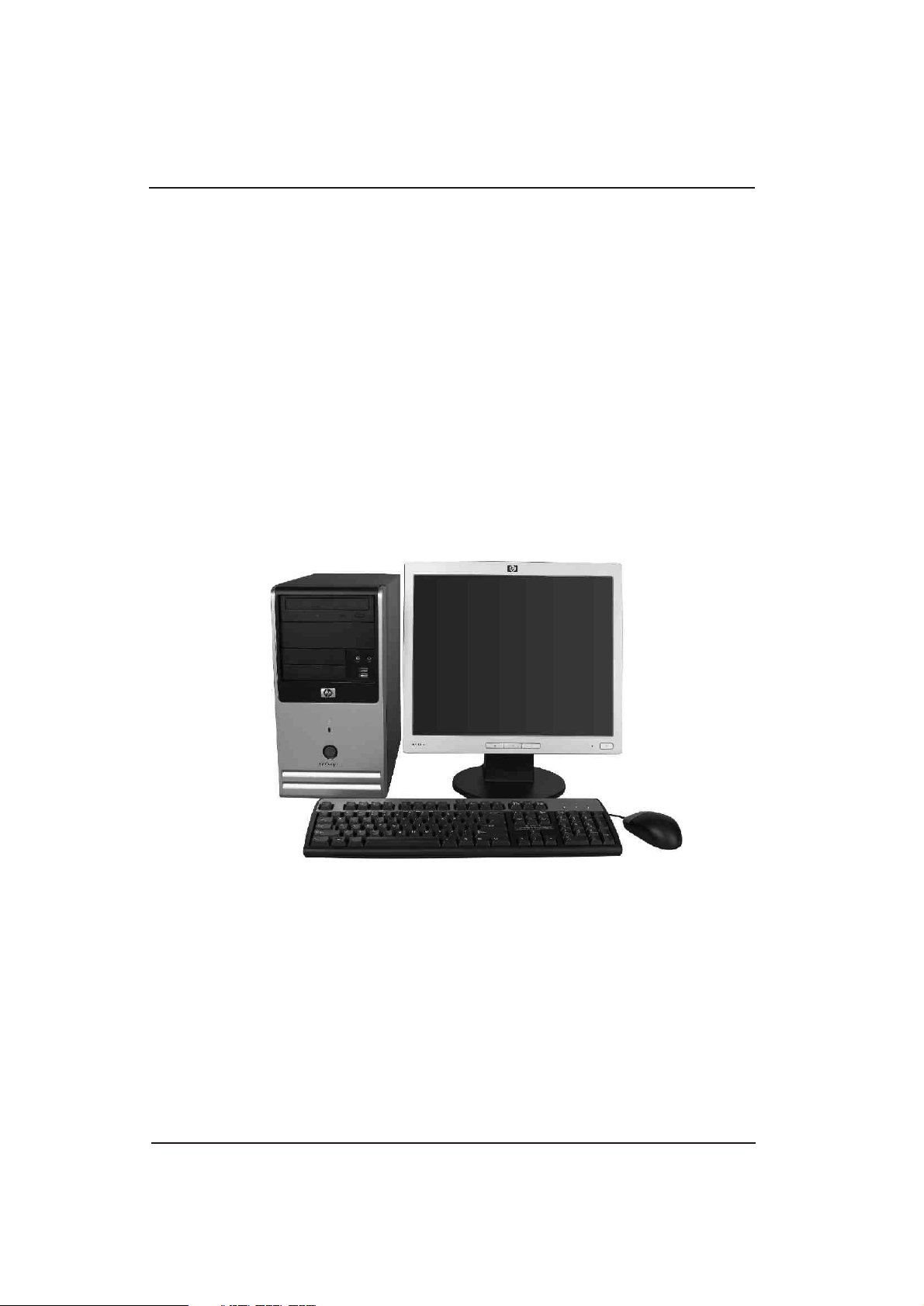
Standard Configuration Features
The HP Compaq Microtower features may vary depending
on the model. For a complete listing of the hardware and
software installed in the computer, run the Diagnostics for
Windows utility. Instructions for using this utility are
provided in the Troubleshooting Guide on the
Documentation and Diagnostics CD.
1
Product Features
Microtower Configuration
Photos depicted may vary as per actual machine
Hardware Reference Guide www.hp.com/in 1-1
Page 7
Product Features
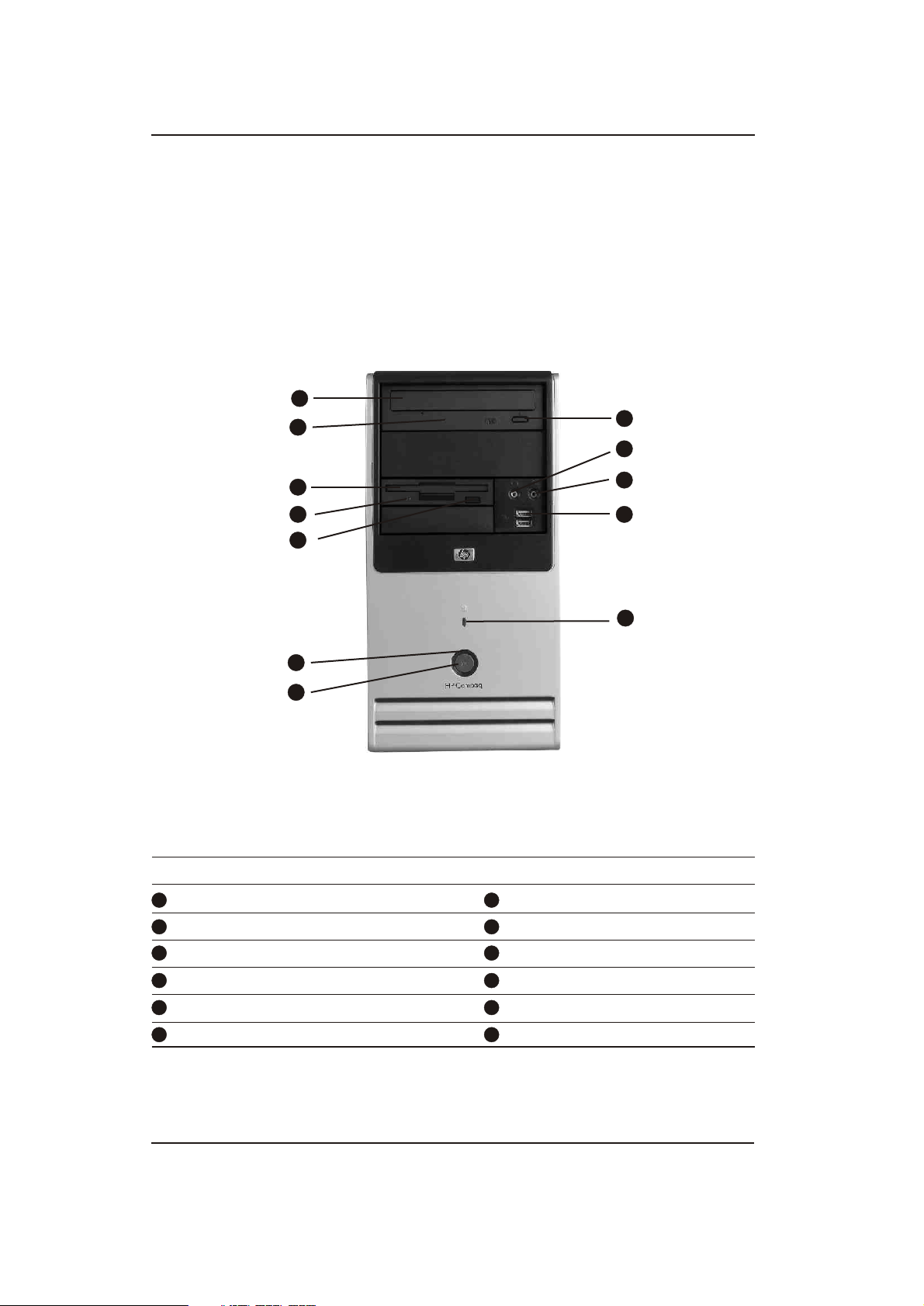
Front Panel Components
Drive configuration may vary by model.
1
2
8
9
3
4
5
6
7
Front Panel Components
1
Optical Drives
2
Optical Drive Activity Lights
3
Diskette Drive (optional)
4
Diskette Drive Activity Light (optional)
Power Button
7
8
Optical Drive Eject Button
9
Headphone Jack
10
Microphone Connector
10
11
1
2
5
Diskette Drive Eject Button (optional)
6
Power On Light
Hardware Reference Guide www.hp.com/in 1-2
11
USB (Universal Serial Bus) Ports
12
Hard Drive Activity Light
Photos depicted may vary as per actual machine
Page 8
Product Features
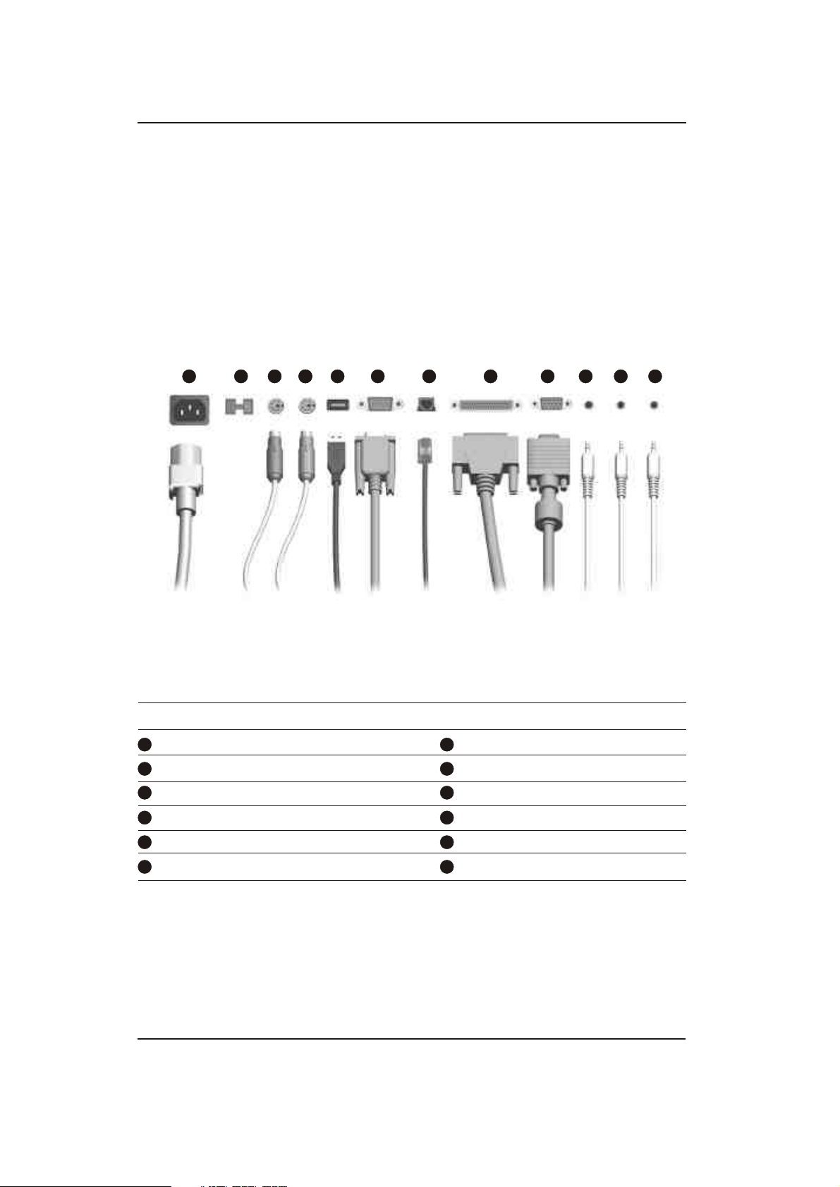
Rear Panel Components
1
2 3 5 6 7 8 10
Rear Panel Components
1 7
2 8
3 9
4 10
5
6
Power Cord Connector RJ-45 Network Connector .
Voltage Select Switch Parallel Port Connector
PS/2 Mouse Connector Monitor Connector
PS/2 Keyboard Connector Headphone/Line-Out Connector
Universal Serial Bus (USB) Audio/Line-In Connector
Serial Port Connector Microphone Connector
11
12
11
944
12
Arrangement and number of connectors may vary by model.
!
Photos depicted may vary as per actual machine
Hardware Reference Guide www.hp.com/in 1-3
Page 9
Product Features
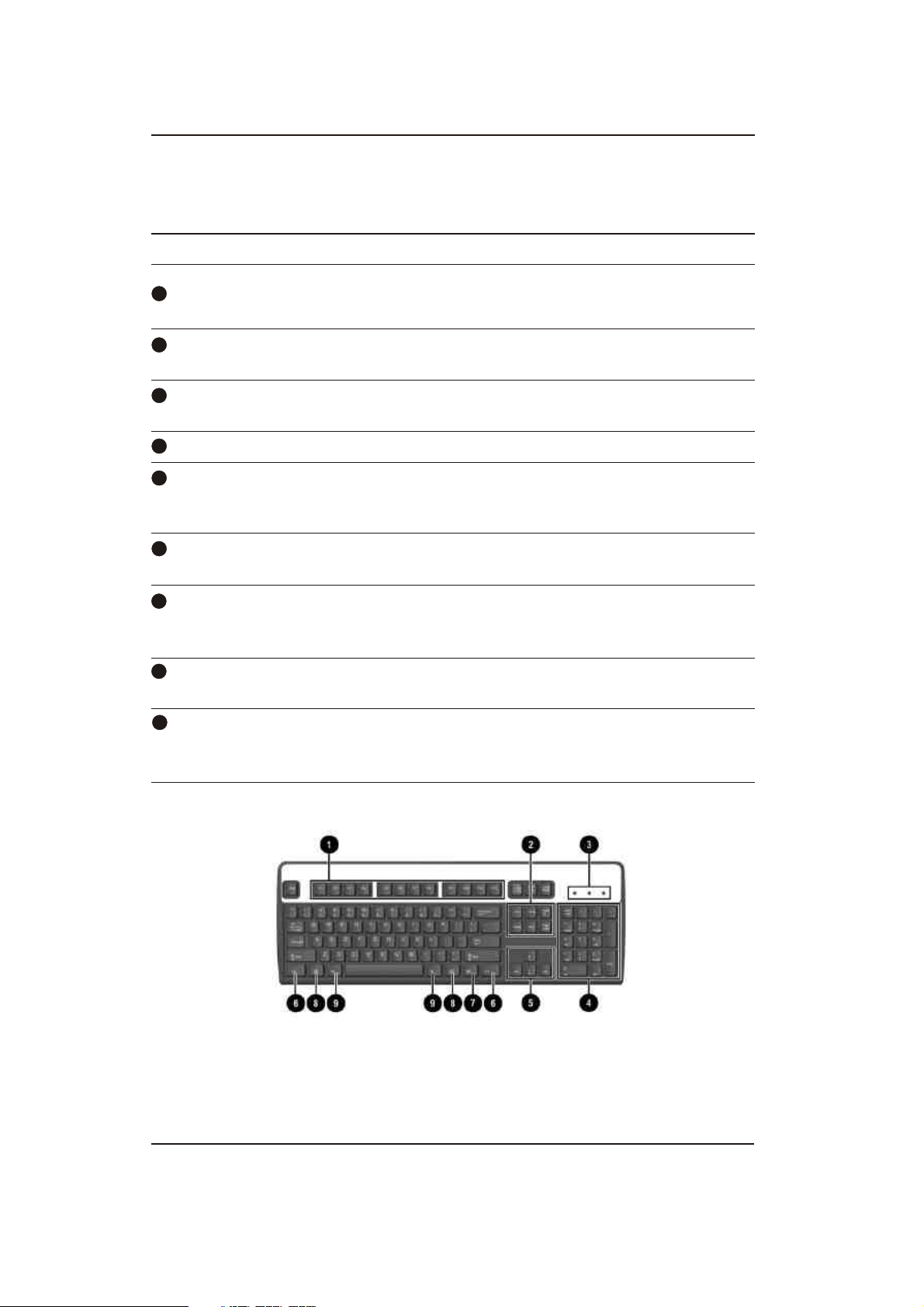
Keyboard
Keyboard Components
1
Function Keys Perform special functions depending on the software
application being used.
2
Editing Keys Includes the following: Insert, Home, Page Up, Delete, End,
and Page Down. .
3
Status Lights Indicate the status of the computer and keyboard settings
(Num Lock, Caps Lock, and Scroll Lock).
4
Numeric Keys Work like a calculator keypad.
5
Arrow Keys Used to navigate through a document or Web site. These
keys allow you to move left, right, up, and down, using the
keyboard instead of the mouse.
6
Ctrl Keys Used in combination with another key; its effect depends
on the application software you are using.
7
Application Key* Used (like the right mouse button) to open pop-up menus
in a Microsoft Office application. May perform other
functions in other software applications.
8
Windows Logo Keys* Used to open the Start menu in Microsoft Windows. Used
in combination with other keys to perform other functions.
9
Alt Keys Used in combination with another key; its effect depends
on the application software you are using. *Keys available
in select geographic regions.
Photos depicted may vary as per actual machine
Hardware Reference Guide www.hp.com/in 1-4
Page 10

Product Features
Windows Logo Key
Use the Windows Logo key in combination with other keys to
perform certain functions available in the Windows operating system.
Refer to the "Keyboard" section to identify the Windows Logo key.
Windows Logo Key Functions
Windows Logo Key Displays or hides the Start menu.
Windows Logo Key + d Displays the Desktop.
Windows Logo Key + m Minimizes all open applications.
Shift + Windows Logo Key + m Undoes Minimize All.
Windows Logo Key + e Launches My Computer.
Windows Logo Key + f Launches Find Document.
Windows Logo Key + Ctrl + f Launches Find Computer.
Windows Logo Key + F1 Launches Windows Help.
Windows Logo Key + l Locks the computer if you are connected to a
network domain, or allows you to switch
users if you are not connected to a network
domain.
Windows Logo Key + r Launches the Run dialog box.
Windows Logo Key + u Launches the Utility Manager.
Windows Logo Key + Tab Activates the next Taskbar button.
Special Mouse Functions
Most software applications support the use of a mouse. The functions
assigned to each mouse button depend on the software applications
you are using.
Hardware Reference Guide www.hp.com/in 1-5
Page 11
Product Features
Serial Number Location
Each computer has a unique serial number and a product ID number
that are located on the top cover of the computer. Keep these numbers
available for use when contacting customer service for assistance.
Serial Number and Product ID Location
Photos depicted may vary as per actual machine
Hardware Reference Guide www.hp.com/in 1-6
Page 12

Serviceability Features
The Microtower computer includes features that make it easy to
upgrade and service. A Torx T-15 screwdriver is needed for many of
the installation procedures described in this chapter.
Warnings and Cautions
Before performing upgrades be sure to carefully read all of the applicable
instructions, cautions, and warnings in this guide.
WARNING: To reduce the risk of personal injury from electrical shock
and/or hot surfaces, be sure to disconnect the power cord from the wall
!
outlet and allow the internal system components to cool before touching.
WARNING: To reduce the risk of electrical shock, fire, or damage to the
!
equipment, do not plug telecommunications/telephone connectors into the
network interface controller (NIC) receptacles.
2
Hardware Upgrades
WARNING: To reduce the risk of electrical shock, before removing the
!
computer cover ensure that telecommunication/telephone connector (TNV
circuit) are disconnected
CAUTION: Static electricity can damage the electrical components of the
computer or optional equipment. Before beginning these procedures,
ensure that you are discharged of static electricity by briefly touching a
grounded metal object. See Chapter 5, "Electrostatic Discharge" for more
information.
CAUTION: Before removing the computer cover, ensure that the computer
is turned off and that the power cord is disconnected from the electrical
outlet.
CAUTION: To reduce the risk of fire, use only No. 26 AWG or larger (e.g.,
24 AWG) UL Listed or CSA Certified Telecommunication Line Cord
Hardware Reference Guide www.hp.com/in 2-1
Page 13
Hardware Upgrades
Removing the Computer Access Panel
CAUTION: CAUTION: Before removing the computer access panel, ensure
that the computer is turned off and that the power cord is disconnected
from the electrical outlet.
To remove the computer access panel:
1. Turn off the computer properly through the operating system and
turn off any external devices.
2. Disconnect the power cord from the power outlet and the
computer, and disconnect any external devices.
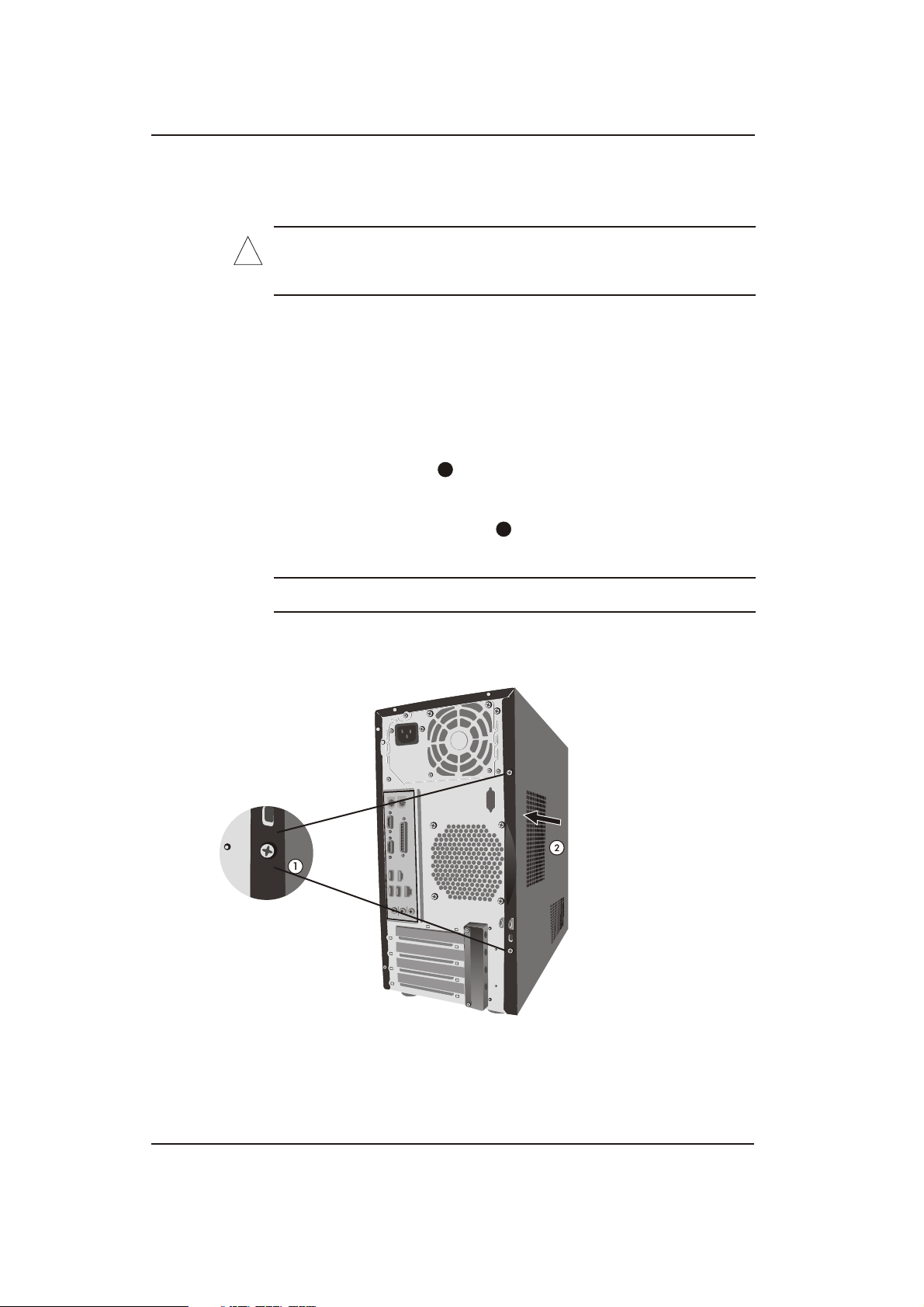
3. Remove the screw that secures the access panel to the
computer chassis.
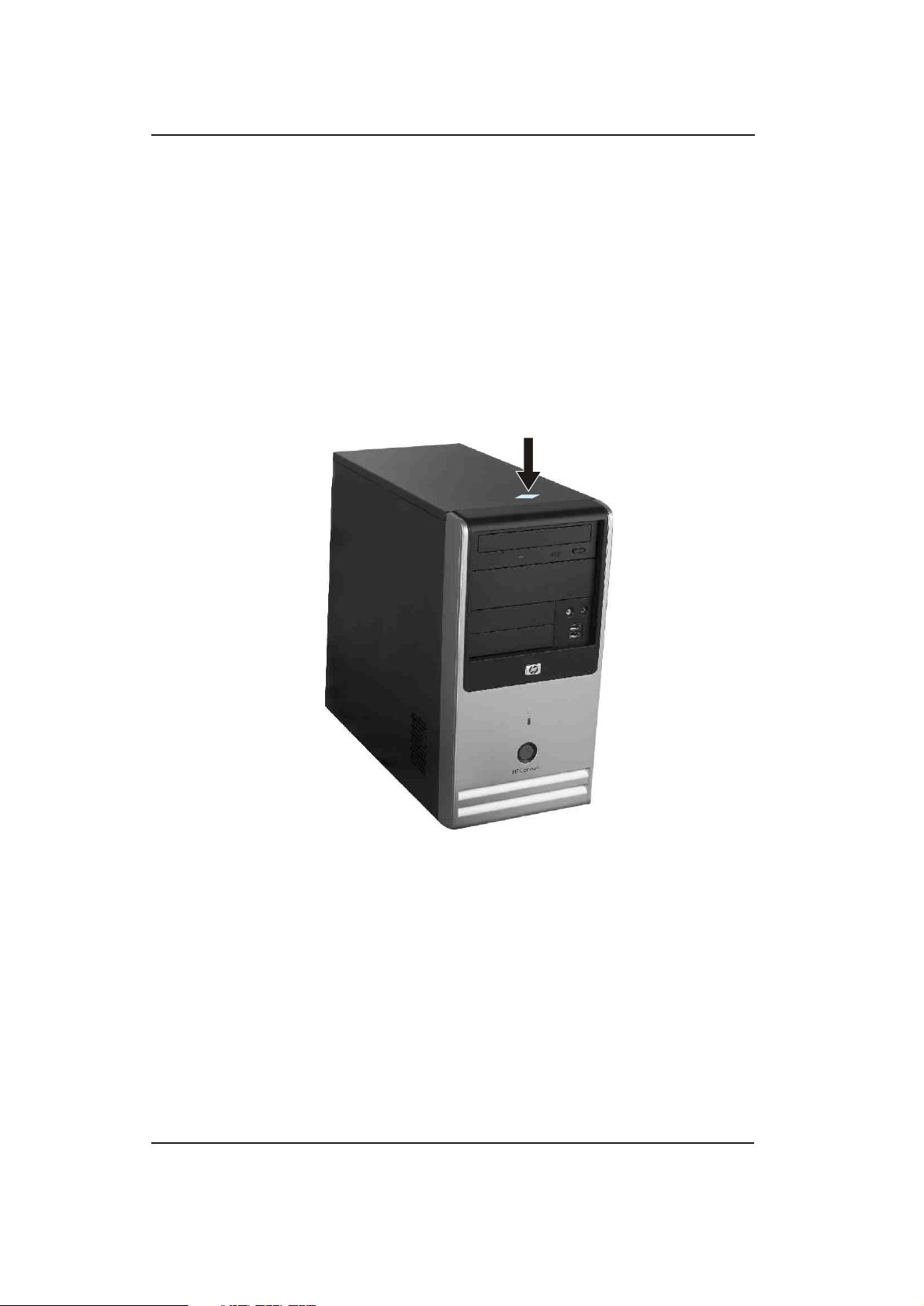
4. Slide the access panel back about 2.5 cm (1 inch), then lift it
off the unit.
To replace the access panel, reverse the removal steps.
!
1
2
Removing the Computer Access Panel
Photos depicted may vary as per actual machine
Hardware Reference Guide www.hp.com/in 2-2
Page 14
Hardware Upgrades
Removing the Front Bezel
To remove the front bezel:
1. Turn off the computer properly through the operating system and turn
off any external devices.
2. Disconnect the power cord from the power outlet and the computer, and
disconnect any external devices.
3. To remove the front bezel, press down on all four tabs
at the bottom of the bezel and then rotate the bezel off the chassis .
1
2
1
Removing the Front Bezel
Photos depicted may vary as per actual machine
Hardware Reference Guide www.hp.com/in 2-3
Page 15

Hardware Upgrades
Installing Additional Memory
The computer comes with double data rate synchronous dynamic
random access memory (DDR2-SDRAM) dual inline memory
modules (DIMMs).
DIMMs
The memory sockets on the system board can be populated with up to
four industry-standard DIMMs. These memory sockets are populated
with at least one preinstalled DIMM. To achieve the maximum
memory support, you can populate the system board with up to 8GB*
of memory configured in a high-performing dual channel mode.
DDR2-SDRAM DIMMs
For proper system operation, if the computer supports DDR2
SDRAM DIMMs, the DIMMs must be:
Industry-standard 240-pin
Unbuffered 800 MHz-compliant
DDR2 800 MHz DIMM
256Mbit, 512Mbit, and 1Gbit non-ECC memory technologies
single-sided and double-sided DIMMS
The system will not start if you install unsupported DIMMs.
!
*8GB Memory is supported only with Windows Vista 64 bit or
!
Freedos operating systems
Hardware Reference Guide www.hp.com/in 2-4
Page 16
Hardware Upgrades
Populating DIMM Sockets
The system will automatically operate in single channel mode, dual
channel Asymmetric mode, depending on how the DIMMs are
installed.
The system will operate in single channel mode if the DIMM
sockets are populated in one channel only.
The system will operate in dual channel Asymmetric mode if the
total memory capacity of the DIMMs in Channel A is not equal to
the total memory capacity of the DIMMs in Channel B.
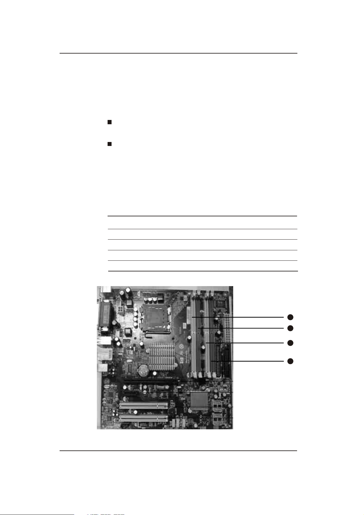
There are Four DIMM sockets on the system board, with two sockets
per channel.
DIMM Socket
Item Description Socket Color
1
2
3
4
DIMM socket, Channel A
DIMM socket, Channel A
DIMM socket, Channel B
DIMM socket, Channel B
Yellow
Red
Yellow
Red
1
2
3
4
Hardware Reference Guide www.hp.com/in 2-5
Page 17

Hardware Upgrades
Installing DIMMs
CAUTION: The memory module sockets have gold metal contacts. When
upgrading the memory, it is important to use memory modules with gold
metal contacts to prevent corrosion and/or oxidation resulting from having
incompatible metals in contact with each other.
CAUTION: Static electricity can damage the electronic components of the
computer or optional cards. Before beginning these procedures, ensure
that you are discharged of static electricity by briefly touching a grounded
metal object. For more informations, refer to Chapter 5, "Electrostatic
Discharge."
CAUTION: When handling a memory module, be careful not to touch any
of the contacts. Doing so may damage the module.
1. Turn off the computer properly through the operating system and
turn off any external devices.
2. Disconnect the power cord from the power outlet and disconnect
any external devices.
3. Remove the computer access panel.
4. Locate the memory module sockets on the system board.
WARNING: To reduce risk of personal injury from hot surfaces, allow the
!
internal system components to cool before touching.
Hardware Reference Guide www.hp.com/in 2-6
Page 18
Hardware Upgrades
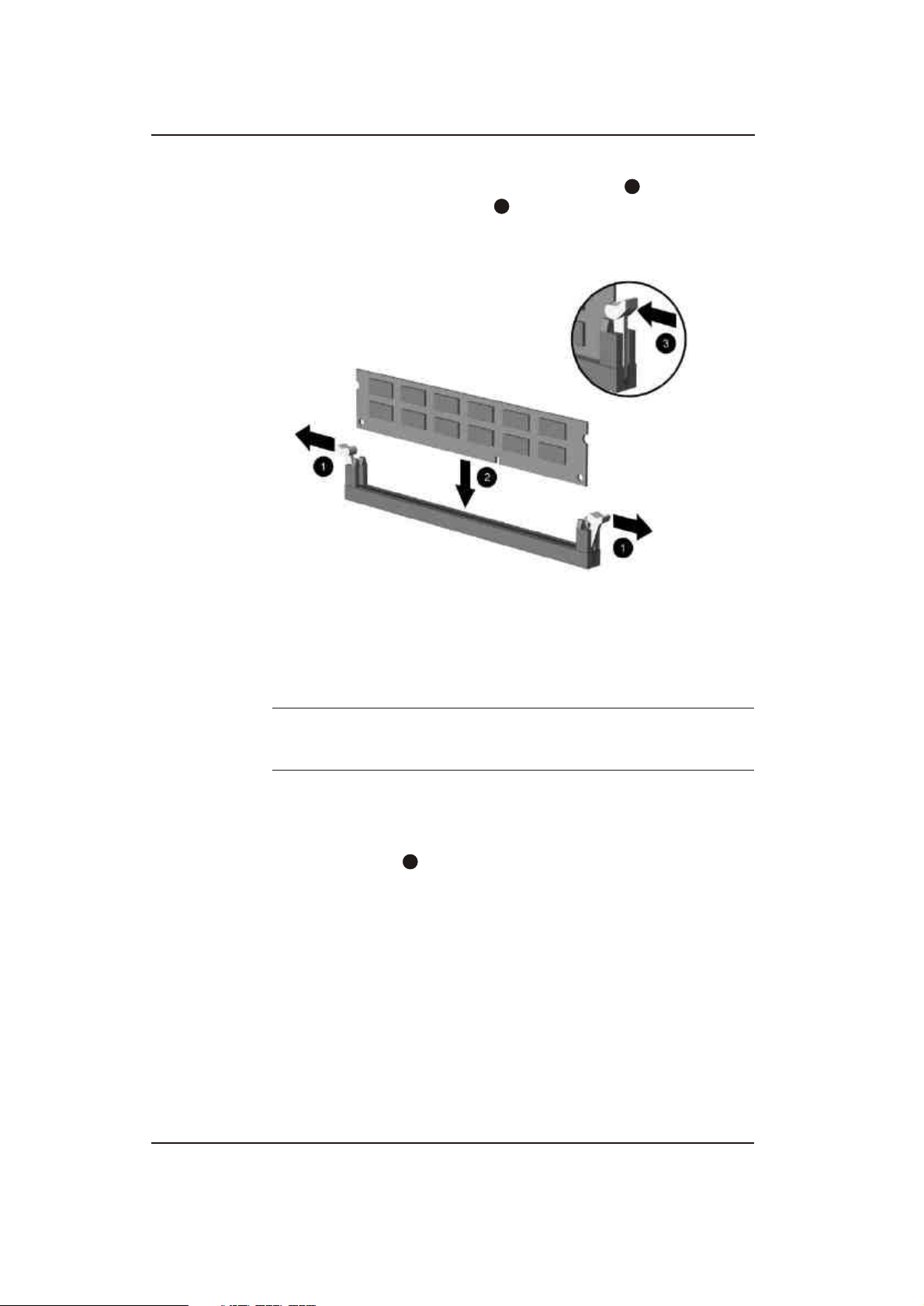
5. Open both latches of the memory module socket , and insert the
memory module into the socket
2
1
Installing a DIMM
A memory module can be installed in only one way. Match the notch
on the module with the tab on the memory socket.
6. Push the module down into the socket, ensuring that the module is
fully inserted and properly seated. Make sure the latches are in the
closed position .
3
7. Repeat steps 5 and 6 to install any additional modules.
8. Replace the access panel.
The computer should automatically recognize the additional memory
the next time you turn on the computer.
Photos depicted may vary as per actual machine
Hardware Reference Guide www.hp.com/in 2-7
Page 19
Hardware Upgrades
Removing a 5.25" Drive Bezel Blank
If the computer was not shipped with a drive in the 5.25" option bay,
the bay will be covered by a bezel blank. If you add a drive to the
option bay, you must first remove the bezel blank.
1. Turn off the computer properly through the operating system and
turn off any external devices.
2. Disconnect the power cord from the power outlet and the
computer, and disconnect any external devices.
3. Remove the access panel and front bezel. Refer to "Removing the
Computer Access Panel" and "Removing the Front Bezel".
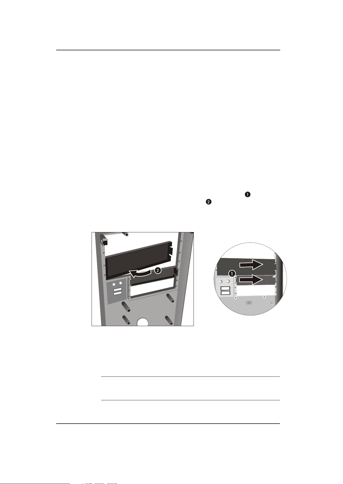
4. While facing the inside of the front bezel, press the two retaining
tabs on the right towards the outer edge of the bezel and pull
the bezel blank inwards to remove it .
Removing a Bezel Blank
To install a bezel blank, slide the left side of the blank into the two
retainer slots on the left side of the front bezel then snap the right side
!
of the blank into place.
Photos depicted may vary as per actual machine
Hardware Reference Guide www.hp.com/in 2-8
Page 20

Hardware Upgrades
Replacing or Upgrading a Drive
The computer supports up to six drives that may be installed in
various configurations.
This section describes the procedure for replacing or upgrading
the storage drives. A Torx screwdriver is needed to remove and
install the guide screws and retainer screws on a drive.
CAUTION: Make sure you back up your personal files on the hard drive to an
external storage device, such as a CD, before removing the hard drive. Failure to do
so will result in data loss. After replacing the primary hard drive, you will need to run
the Restore Plus! DVD to load the HP factory-installed files.
Hardware Reference Guide www.hp.com/in 2-9
Page 21

Hardware Upgrades
Locating Drive Positions
2
Drive Positions
Photos depicted may vary as per actual machine
Hardware Reference Guide www.hp.com/in 2-10
3
Page 22
Hardware Upgrades
First 5.25-inch, half-height bays for optional drives Second 5.25-inch,
half-height bays for optional drives
2
Two Nos. standard 3.5-inch, one-third height bays
(1.44-MB diskette drive shown)
3
Two Nos. internal 3.5-inch, one-third height bays for hard drives
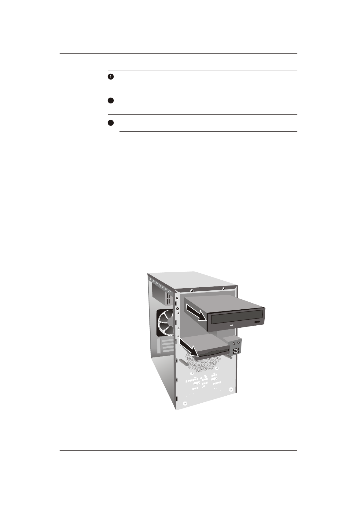
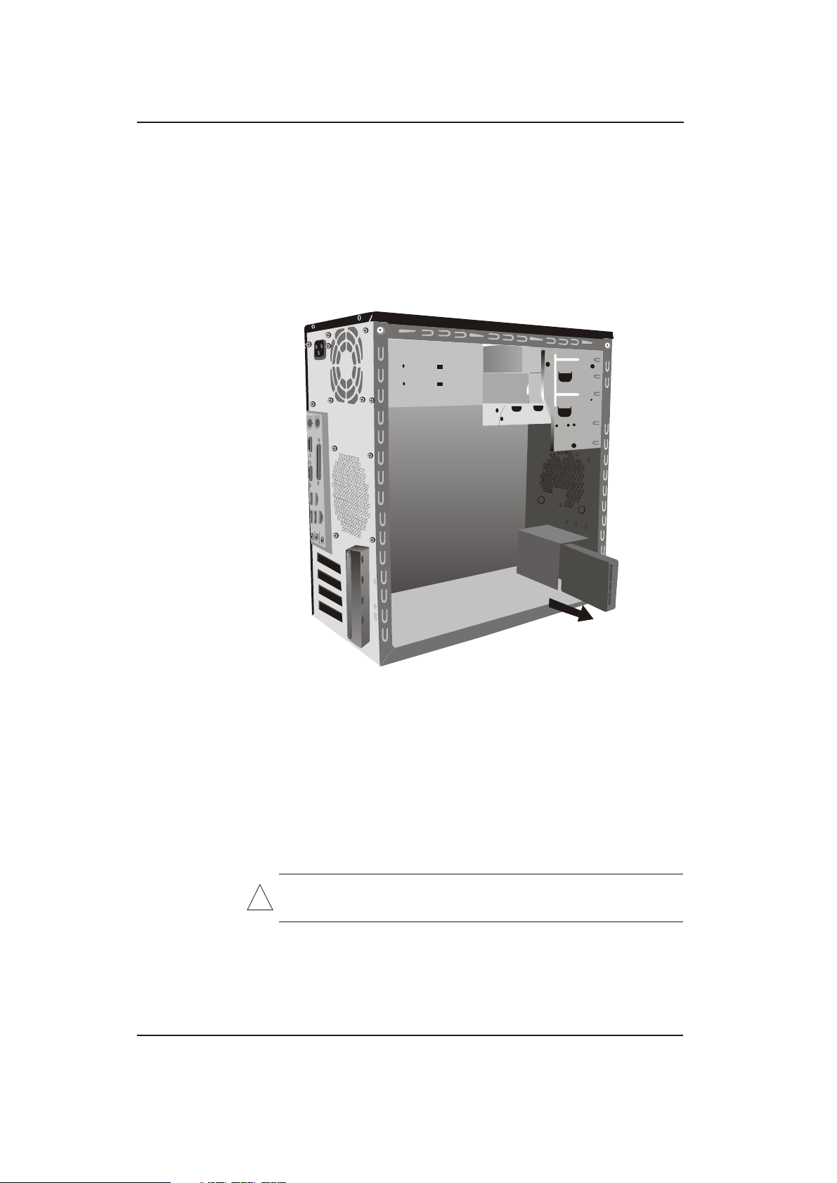
Removing a Drive
1. Turn off the computer properly through the operating system and
turn off any external devices. Disconnect the power cord from the
power outlet and disconnect any external devices. .
2. Remove the access panel and front bezel.
3. Disconnect the power and data cables from the back of the drive,
as indicated in the following illustrations.
4. Remove all the screws that secures the drives in the drive bay.
Slide the drive disk forward and out of the bay.
Removing the Drives
Photos depicted may vary as per actual machine
Hardware Reference Guide www.hp.com/in 2-11
Page 23
Hardware Upgrades
5. Hard disk is inserted or slide out from the back.
Removing the Hard disk
6. Remove all the screws that secure the floppy drive in the bay.
Slide the drive disk forward and out of the bay.
WARNING: There may be sharp edges on the insides of the bay
!
opening after the shield has been removed.
Photos depicted may vary as per actual machine
Hardware Reference Guide www.hp.com/in 2-12
Page 24

Hardware Upgrades
Replacing a Drive
CAUTION: To prevent loss of work and damage to the computer or drive:
If you are inserting or removing a hard drive, shut down the operating system
properly, then turn off the computer. Do not remove a hard drive while the
computer is on or in standby mode.
Before handling a drive, ensure that you are discharged of static electricity.
While handling a drive, avoid touching the connector. For more information
about preventing electrostatic damage, refer to Chapter 5, "Electrostatic
Discharge."
Handle a drive carefully; do not drop it.
Do not use excessive force when inserting a drive.
Avoid exposing a hard drive to liquids, temperature extremes, or products that
have magnetic fields such as monitors or speakers.
Make sure to back up the data on the old hard drive before removing
!
it so that you can install the data onto the new hard drive.
Hardware Reference Guide www.hp.com/in 2-13
Page 25
Hardware Upgrades
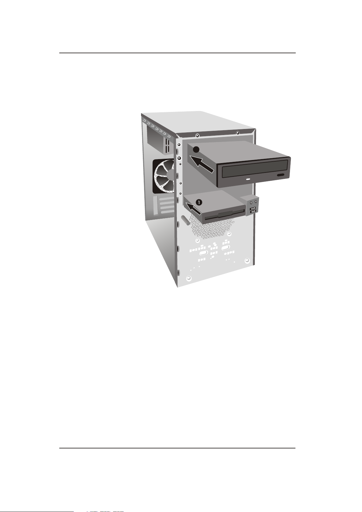
1. Slide the floppy drive into the drive bay, making sure to align
the guide screws with the guide slots, until the drive snaps into
place.
2
Sliding the Drives into the Drive Cage
2. Slide the optical drive into the drive bay, making sure to align
the screw holes with the drive bays holes. Secure the Drive by
tighten all two screws.
Photos depicted may vary as per actual machine
Hardware Reference Guide www.hp.com/in 2-14
Page 26

Hardware Upgrades
3. Slide in the hard disk from the front to back, making sure to
align the screw holes with the drive bays holes. Secure the Drive
by tighten all the screws at each bottom side
3
Sliding the Hard Drive into the Drive Cage
Photos depicted may vary as per actual machine
Hardware Reference Guide www.hp.com/in 2-15
Page 27

Hardware Upgrades
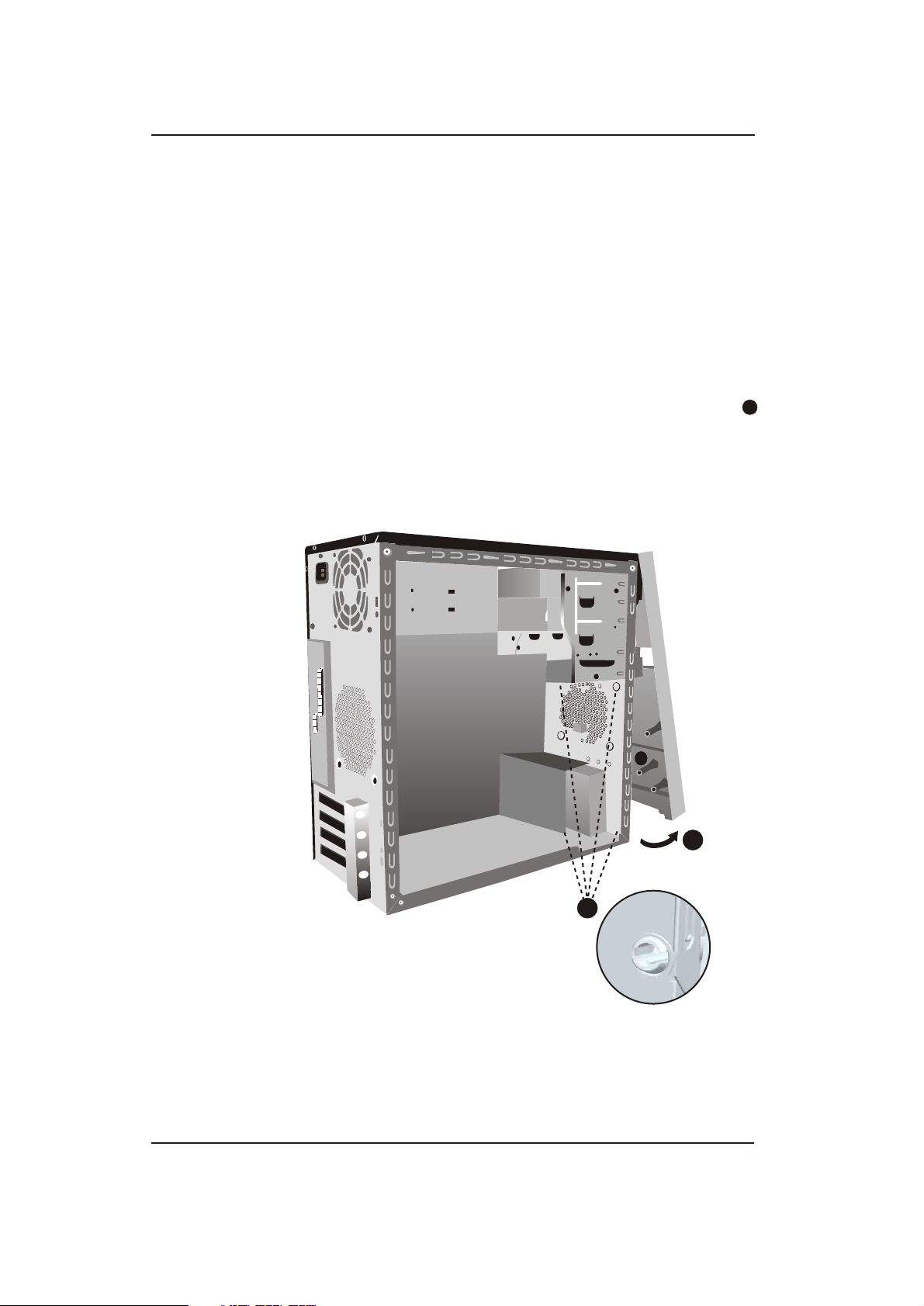
Install Second Hard Disk
A second Hard disk should be installed as per following
1
1. Secure hard drive in hard drive bay located in
(as indicated by arrow ).
1
2. Secure the second hard drive by tightening the 2 screws at
bottom.
Photos depicted may vary as per actual machine
Hardware Reference Guide www.hp.com/in 2-16
Page 28

Hardware Upgrades
3. Connect one end of the data cables to the second hard drive as
shown above.
4. The other end connect to the system board.
Photos depicted may vary as per actual machine
Hardware Reference Guide www.hp.com/in 2-17
Page 29

Hardware Upgrades
5. Complete the procedure described in the "Reassembling the
Computer" section of this chapter.
6. Turn on the computer.
If you replaced the primary hard drive, insert the Restore Plus!
DVD to restore the operating system, software drivers, and/or any
!
software applications that were preinstalled on the computer
from HP. Follow the instructions in the guide included with the
restore DVD. When the restore process has completed, reinstall
any personal files that you backed up before replacing the hard
drive.
Hardware Reference Guide www.hp.com/in 2-18
Page 30

Hardware Upgrades
Removing or Installing an Expansion Card
This computer has two PCI expansion slots, one PCI-Express x 1 &
one PCI-Express x 16 slots
Expansion Slot Locations
Photos depicted may vary as per actual machine
PCI -
E x16 Slot
PCI -E x1 Slot
PCI Slot
PCI Slot
Hardware Reference Guide www.hp.com/in 2-19
Page 31

Hardware Upgrades
To remove, replace, or add an expansion card.
1. Turn off the computer properly through the operating system and
turn off any external devices. Disconnect the power cord from
the power outlet and disconnect any external devices.
2. Remove the access panel and lay the computer on its side with
the opening to internal parts where the access panel was located
facing up.
3. On the rear panel of the computer, remove the screw that secures
the slot cover lock in place and slide the slot cover lock away
from the slots to remove it from the computer .
Releasing the Slot Cover Lock
Photos depicted may vary as per actual machine
Hardware Reference Guide www.hp.com/in 2-20
Page 32

Hardware Upgrades
4. Before installing an expansion card, remove the expansion slot
cover or the existing expansion card.
a. If you are installing an expansion card in a vacant socket,
remove the appropriate expansion slot cover on the back of
the chassis. Pull the slot cover straight up from the socket
then away from the inside of the chassis.
Removing an Expansion Slot Cover
Photos depicted may vary as per actual machine
Hardware Reference Guide www.hp.com/in 2-21
Page 33

Hardware Upgrades
b. If removing a standard PCI expansion card, hold the card at
each end, and carefully rock it back and forth until the
connectors pull free from the socket. Pull the expansion card
straight up from the socket then away from the inside of
the chassis to release it from the chassis frame. Be sure not
2
1
to scrape the card against the other components.
Removing an Expansion Card
Photos depicted may vary as per actual machine
Hardware Reference Guide www.hp.com/in 2-22
Page 34

Hardware Upgrades
5. If replacing or adding a new expansion card, hold the card just
above the expansion slot on the system board then move the card
toward the rear of the chassis so that the bottom of the
1
bracket on the card slides into the small slot on the chassis.
Gently press the card straight down into the expansion slot on
the system board .
2
Replacing or Adding an Expansion Card
6. While holding the expansion card bracket against the chassis,
slide the slot cover lock down toward the expansion card bracket
to secure it in place and replace the screw that secures the slot
cover lock.
7. Connect the external cables to the installed card, if needed.
Connect internal cables to the system board, if needed.
8. Replace the computer access panel and reconnect the power
cable.
When installing an expansion card, press firmly on the card so that
the whole connector seats properly in the expansion card slot.
Photos depicted may vary as per actual machine
Hardware Reference Guide www.hp.com/in 2-23
Page 35

Hardware Upgrades
9. If you are replacing an expansion card, store the old card in the
anti-static packaging that contained the new card.
10. While holding the expansion card bracket against the chassis,
slide the slot cover lock down toward the expansion card
brackets and slot covers to secure them in place and replace
the screw that secures the slot cover lock.
2
1
Securing the Expansion Cards and Slot Covers
11. Complete the procedure described in the "Reassembling the
Computer" section of this chapter.
Photos depicted may vary as per actual machine
Hardware Reference Guide www.hp.com/in 2-24
Page 36

Hardware Upgrades
Reassembling the Computer
1. Position the chassis in the upright position. Insert the four tabs at
the bottom of the bezel . Snap into the slots of the chassis.
Align the two hooks on the top of the bezel into the rectangular
holes on the chassis then rotate the bezel into the place .
1
2
Replacing the Front Bezel
Photos depicted may vary as per actual machine
Hardware Reference Guide www.hp.com/in 2-25
Page 37

Hardware Upgrades
2. Place the side access panel in the proper position on the chassis
and slide it into place . Ensure that the hole for the screw is
aligned with the hole in the chassis and tighten the screw .
2
1
2
1
2
Replacing the Side Access Panel
3. Reconnect the power cable to the computer and plug the cable
into an electrical outlet.
4. Reconnect all peripheral devices to the computer.
WARNING: To reduce the risk of electrical shock, fire, or damage to the
!
equipment, do not plug telecommunications or telephone connectors into
the network interface controller (NIC) ports.
5. Turn on the computer by pressing the power button.
Photos depicted may vary as per actual machine
Hardware Reference Guide www.hp.com/in 2-26
Page 38

Battery Replacement
The battery that comes with the computer provides power to the realtime clock. When replacing the battery, use a battery equivalent to the
battery originally installed in the computer. The computer comes with
a 3-volt lithium coin cell battery.
The lifetime of the lithium battery can be extended by plugging the
!
computer into a live AC wall socket. The lithium battery is only used
when the computer is NOT connected to AC power.
WARNING: The computer contains an internal lithium manganese dioxide
!
battery. There is a risk of fire and burns if the battery is not handled
properly. To reduce the risk of personal injury:
Do not attempt to recharge the battery.
Do not expose to temperatures higher than 60°C (140ºF).
Do not disassemble, crush, puncture, short external contacts, or
dispose of in fire or water.
Replace the battery only with the HP spare designated for this
product.
3
CAUTION: Before replacing the battery, it is important to back up the computer
CMOS settings. When the battery is removed or replaced, the CMOS settings will
be cleared. Refer to the Troubleshooting Guide on the Documentation and
Diagnostics CD for information on backing up the CMOS settings.
Batteries, battery packs, and accumulators should not be disposed of togethe
with the general household waste. In order to forward them to recycling or
proper disposal, please use the public collection system or return them to HP, their
authorized partners, or their agents.
Hardware Reference Guide www.hp.com/in 3-1
Page 39

CAUTION: Static electricity can damage the electronic components of the
computer or optional equipment. Before beginning these procedures, ensure that
you are discharged of static electricity by briefly touching a grounded metal object.
1. Turn off the computer properly through the operating system,
then turn off any external devices.
2. Disconnect the power cord from the power outlet and disconnect
any external devices. Then remove the computer access panel.
It may be necessary to remove an expansion card to gain access to the
!
battery.
3. Locate the battery and battery holder on the system board.
4. Depending on the type of battery holder on the system board,
complete the following instructions to replace the battery.
a.To release the battery from its holder, squeeze the metal
clamp that extends above one edge of the battery. When the
battery pops up, lift it out .
b.To insert the new battery, slide one edge of the replacement
battery under the holder's lip with the positive side up. Push
the other edge down until the clamp snaps over the other edge
of the battery .
2
1
Hardware Reference Guide www.hp.com/in 3-2
Page 40

Removing and Replacing a Coin Cell Battery
After the battery has been replaced, use the following steps to
!
complete this procedure.
5. Replace the computer access panel.
6. Plug in the computer and turn on power to the computer.
7. Reset the date and time, your passwords, and any special system
setups, using Computer Setup. Refer to the Computer Setup
(F10) Utility Guide on the Documentation and Diagnostics CD.
Power Supply Notice
WARNING: The power supply contains hazardous moving parts.
!
Keep fingers and other body parts away from ventilation openings.
Power Supply Label
The following label or equivalent is located on the surface of power supply:
WARNING : HAZARDOUS MOVING PARTS
KEEP FINGERS AND OTHER BODY PARTS AWAY
Power Supply Label
WARNING: System and CPU fans contain hazardous moving parts.
!
keep fingers and other body parts aways
System and CPU fan label
WARNING: System and CPU fans contain hazardous moving parts.
keep fingers and other body parts aways
WARNING : HAZARDOUS MOVING PARTS
KEEP FINGERS AND OTHER BODY PARTS AWAY
Photos depicted may vary as per actual machine
Hardware Reference Guide www.hp.com/in 3-3
Page 41

Security Lock Provisions
Installing a Security Lock
The security locks displayed on the below page can be used to secure the Microtower
computer by putting a mechanical lock
Mechanical Lock
Installing a Mechanical Lock
4
Chassis Intrusion Switch
Chassis Intrusion (CI) Switch, is a combination of hardware and software technology that can alert you when the
computer cover or side panel has been removed. There are various levels of protection, as described in the
following table.
Status /Mode Description
System switched off and power
plug completely removed,
completely OFF mode
Power cable plugged in (power
ON) , but System in Shutdown
Mode
System in Power Management
Mode
System in Running/User Mode
!
To achieve this functionality please refer to computer setup, see the Computer Setup
(F10) Utility Guide.
When the computer is restarted, the screen displays a message indicating that
the computer cover or side panel has been removed. Make sure that any system
access was authorized and press F1 to continue
When the computer is restarted, the screen displays a message indicating that
the computer cover or side panel has been removed. Make sure that any system
access was authorized and press F1 to continue
At the next boot, the screen displays a message indicating that the computer
cover or side panel has been removed. Make sure that any system access was
authorized and press F1 to continue
The user is notified at the next boot with a message indicating that the
computer cover or side panel has been removed. Ensure that any system access
was authorized and press F1 to continue
Photos depicted may vary as per actual machine
Setting the Chassis Intrusion Switch
To set the CI Protection, complete the following
steps:
1. Fix the CI Switch on the Back panel of Chassis
as directed in the diagram.
2. Connect the CI Switch cable to the CI Pins on
the system motherboard.
3. Fix the Side panel/cover on the chassis.
Installing CI switch at the back panel
!
Hardware Reference Guide www.hp.com/in 4-1
For maximum security, be sure to establish a setup password.
The setup password prevents unauthorized access to the Computer Setup utility
Connecting CI switch to CI pins
on motherboard
Page 42

Electrostatic Discharge
A discharge of static electricity from a finger or other conductor may
damage system boards or other static-sensitive devices. This type of
damage may reduce the life expectancy of the device.
Preventing Electrostatic Damage
To prevent electrostatic damage, observe the following precautions:
n Avoid hand contact by transporting and storing products in
static-safe containers.
n Keep electrostatic-sensitive parts in their containers until they
arrive at static-free workstations.
n Place parts on a grounded surface before removing them from
their containers.
n Avoid touching pins, leads, or circuitry.
n Always be properly grounded when touching a static-sensitive
component or assembly.
5
Grounding Methods
There are several methods for grounding. Use one or more of the
following methods when handling or installing electrostatic-sensitive
parts:
n Use a wrist strap connected by a ground cord to a grounded
workstation or computer chassis. Wrist straps are flexible straps
with a minimum of 1 megohm +/- 10 percent resistance in the
ground cords. To provide proper ground, wear the strap snug
against the skin.
Hardware Reference Guide www.hp.com/in 5-1
Page 43

n Use heelstraps, toestraps, or bootstraps at standing workstations.
Wear the straps on both feet when standing on conductive floors
or dissipating floor mats.
n Use conductive field service tools.
n Use a portable field service kit with a folding static-dissipating
work mat.
If you do not have any of the suggested equipment for proper
grounding, contact an HP authorized dealer, reseller, or service
provider.
For more information on static electricity, contact an HP authorized
!
dealer, reseller, or service provider.
Hardware Reference Guide www.hp.com/in 5-2
Page 44

6
Computer Operating Guidelines,
Routine Care and Shipping Preparation
Computer Operating Guidelines and Routine Care
Follow these guidelines to take care of the computer and monitor:
n Operate the computer on a sturdy, level surface. Leave a 10.2-
cm (4-inch) clearance at the back of the system unit and above
the monitor to permit the required airflow.
n Never operate the computer with the cover or side panel
removed.
n Never restrict the airflow into the computer by blocking the front
vents or air intake. Do not place the keyboard, with the keyboard
feet down, directly against the front of the desktop unit as this
also restricts airflow.
n Keep the computer away from excessive moisture, direct
sunlight, and extremes of heat and cold.
n Keep liquids away from the computer and keyboard.
n Never cover the ventilation slots on the monitor with any type of
material.
n Install or enable power management functions of the operating
system or other software, including sleep states.
n Turn off the computer before you do either of the following:
Wipe the exterior of the computer with a soft, damp cloth as
needed. Using cleaning products may discolor or damage the
finish.
Occasionally clean the air vents on the front and back of the
computer. Lint and other foreign matter can block the vents
and limit the airflow.
Hardware Reference Guide www.hp.com/in 6-1
Page 45

Optical Drive Precautions
Be sure to observe the following guidelines while operating or
cleaning the optical drive.
Operation
Cleaning
Safety
n Do not move the drive during operation. This may cause it to
malfunction during reading.
n Avoid exposing the drive to sudden changes in temperature, as
condensation may form inside the unit. If the temperature
suddenly changes while the drive is on, wait at least one hour
before you turn off the power. If you operate the unit
immediately, it may malfunction while reading.
n Avoid placing the drive in a location that is subject to high
humidity, extreme temperatures, mechanical vibration, or direct
sunlight.
n Clean the panel and controls with a soft, dry cloth or a soft cloth
lightly moistened with a mild detergent solution. Never spray
cleaning fluids directly on the unit.
n Avoid using any type of solvent, such as alcohol or benzene,
which may damage the finish.
If any object or liquid falls into the drive, immediately unplug
the computer and have it checked by an authorized HP service
provider.
Hardware Reference Guide www.hp.com/in 6-2
Page 46

Shipping Preparation
Follow these suggestions when preparing to ship the computer:
1. Back up the hard drive files on PD discs, tape cartridges, CDs, or
diskettes. Be sure that the backup media is not exposed to
electrical or magnetic impulses while stored or in transit.
The hard drive locks automatically when the system power
!
is turned off.
2. Remove and store any program diskettes from the diskette
drives.
3. Insert a blank diskette into the diskette drive to protect the drive
while in transit. Do not use a diskette on which you have stored
or plan to store data.
4. Turn off the computer and external devices.
5. Disconnect the power cord from the electrical outlet, then from
the computer.
6. Disconnect the system components and external devices from
their power sources, then from the computer.
Ensure that all boards are seated properly and secured in the board
!
slots before shipping the computer.
7. Pack the system components and external devices in their
original packing boxes or similar packaging with sufficient
packing material to protect them.
Hardware Reference Guide www.hp.com/in 6-3
Page 47

Computer Setup (F10) Utility
Guide
HP Compaq Business Desktop
dx2480
Microtower Model
March 2008
This guide provides instructions on how to use Computer Setup. This
tool is used to reconfigure and modify computer default settings when
new hardware is installed and for maintenance purposes.
Page 48

Copyright 2008 Hewlett-Packard Development Company,L.P.The information
contained herein is subject to change without notice.
Microsoft, MS-DOS, Windows and Windows Vista are trademarks of Microsoft
Corporation in the U.S. and other countries.
The only warranties for HP products and services are set forth in the express
warranty statements accompanying such products and services. Nothing herein
should be construed as constituting an additional warranty.HP shall not be liable for
technical or editorial errors or omissions contained herein.
This document contains proprietary information that is protected by copyright. No
part of this document may be photocopied,reproduced or translated to another
language without the prior written consent of Hewlett-Packard Company.
WARNING: Text set off in this manner indicates that failure to follow directions
!
could result in bodily harm or loss of life.
CAUTION: Text set off in this manner indicates that failure to follow directions
could result in damage to equipment or loss of information.
Computer Setup (F10) Utility Guide
HP Compaq Business Desktop dx2480 Microtower Model
Page 49

Contents
Computer Setup (F10) Utility
Computer Setup (F10) Utilities ……………………………………………………….... 7-1
Using Computer Setup (F10) Utilities …………………………………………….. 7-2
System Information …….………………………………………………......…………. 7-3
S/N …………………………………………………………………………………… 7-4
Product Name ….……………………………………………………………………..... 7-4
Set OwnerShip TAG [Press Enter] …………………………………………………….. 7-4
OwnerShip TAG ……………………………………………………………………….. 7-4
BIOS version …………………………...……………………………………………… 7-4
BIOS Release Date ………………...………………………………………………….. 7-4
System Chipset Type …………………………………………...……………………… 7-4
Processor Type ……………..………………………………………………………….. 7-4
Processor Speed ………………………..………………………………………………. 7-4
CPU ID ……………………..…………………………………………………………. 7-4
L1 Cache Size ………………………………………………………………………. 7-4
L2 Cache Size ...………………………….……………………………………………. 7-4
Memory DIMM1 .………………………………………………………………….. 7-4
Memory DIMM2 ………………………………………………………………………. 7-4
Memory DIMM3 ….........................................……………………………………… 7-4
Memory DIMM4 ………………………………………………………………………. 7-4
DDR Memory size …………………………………………………………………….. 7-4
UUID …………………………………………………………………………………. . 7-4
Chassis Serial Number ………………………………………………………………… 7-4
Set Asset TAG Number[Press Enter] ……………………………………………….. … 7-4
Asset TAG Number ……………………………………………………………………. 7-4
Integrated MAC …………………………………………………………................... 7-4
Standard CMOS Feature …………………………………………………………….... 7-4
System Date …………………………………………………………………………... 7-4
System Time ……………………………………………………………...................... 7-4
SATA PORT 0 ...……………………………………………………………………….. 7-4
SATA PORT 1 ..……………………………………………………………………….. 7-4
SATA PORT 2 ….....……………………………………………………………………. 7-4
SATA PORT 3 ….....…………………………………………………………………… 7-4
IDE Channel 0 &1Master …………………………………………………………….. 7-5
Access Mode …………...……………………………………………………………… 7-5
Halt On ……………………………………………………………………………….. 7-5
SATA Controller ……………………………………………………………………… 7-5
LEGACY Mode Support …………………………………………………………… 7-5
Advanced BIOS Features …………………………………………………………… 7-5
Quick Power On Self Test …………………………………………………………. 7-6
Hard Disk Boot Priority………………………………………………………………. 7-6
CDROM Boot Priority………………………………………………………………… 7-6
Computer Setup (F10) Utility Guide www.hp.com/in iii
Page 50

Contents
First Boot Device ……………………………………………………………………… 7-6
Second Boot Device ………………………………………………………………....... 7-6
Third Boot Device……………………………...……………………………………… 7-6
Boot Other Device ...............................………………...........................… 7-6
APIC Mode…………………………………………………………………………… 7-6
Security option………………………………………………………………………… 7-6
F7(Diagnostic)Support………………………………………………………………. 7-6
F11 Prompt……………………………………………………………………………….7-6
Advanced Chipset Features………………………………………………………………7-6
PEG/Onchip VGA Controller…………………………………………………………… 7-6
On-Chip Frame Buffer Size…………………………………………………………… 7-6
DVMT Mode……………………………………………………………………………. 7-6
IGD DVMT/Fixed Memory…………………………………………………………… 7-7
Integrated Peripherals………………………………………………………………….7-7
USB Controller…………………………………………………………………………. 7-7
USB Legacy Support…………………………………………………………………… 7-7
Azalia Codec…………………………………………………………………………. 7-7
Onboard LAN………………………………………………………………………….7-7
Onboard LAN Boot ROM………………………………………………………………. 7-7
Serial Port……………………………………………………………………………….. 7-7
Parallel Port…………………………………………………………………………….. 7-7
Parallel Port Mode……………………………………………………………………… 7-7
ECP Mode Use DMA…………………………………………………………………. 7-7
Power Management Setup……………………………………………………………… 7-8
ACPI Function………………………………………………………………………….. 7-8
ACPI Suspend Type…………………………………………………………………… 7-8
Restore On AC/Power Loss…………………………………………………………… 7-8
Resume On PCI PME……………………………………………………………….... 7-8
Resume On PCI-E PME …………………………………………………………… 7-8
Wake On Ring………………………………………………………………….....… 7-8
Resume On Alarm…………………………………………………………………….. 7-8
Date(of Month)Alarm………………………………………………………………… 7-8
Time(hh:mm:ss)Alarm…………………………………………………………........ 7-8
HPET Mode…………………………………………………………………………..... 7-8
Hardware Monitor Setup…………………………………………………………….... 7-9
Reset Case Open Status……………………………………………………………..… 7-9
Case Opened………………………………………………………………………….... 7-9
CPU Temperature…………………………………………………………………….... 7-9
CPU Fan Speed……………………………………………………………………… 7-9
System Temperature…………………………………………………………………… 7-9
System Fan Speed…………………………………………………………………….. 7-9
CPU Fan Fault Detect………………………………………………………………… 7-9
System Fan Fault Detect……………………………………………………………… 7-9
Load Default Settings………………………………………………......................... 7-9
Set Supervisor Password……………………………………………………………… 7-9
Set User Password……………………………………………………………………. 7-9
Save Settings and Exit…………………………………………………………………… 7-9
Exit Without Saving……………………………………………………………………. 7-9
Computer Setup (F10) Utility Guide www.hp.com/in iv
Page 51

Computer Setup (F10) Utility
Computer Setup (F10) Utilities
n
Use Computer Setup (F10) Utility to do the following;
Change factory default settings.
n
Set the system date and time.
n
Set,view,change,or verify the system configuration,including
n
settings for processor, graphics, memory, audio, storage,
communications,and input devices.
Modify the boot order of bootable devices such as hard drives,
n
optical drives,orUSB flash media devices.
Enable or disable Quick Power-On Self Test,which is faster than a
n
full boot but does not run all of the diagnostic tests run during a
full boot.
7
n
Enter the Asset Tag or property identification number assigned by
the company to this computer.
n
Establish a supervisor password that controls access to Computer
Setup (F10) Utility and the settings described in this section.
To secure integrated I/O functionality,including the serial,USB,or
n
parallel ports,audio,or embedded NIC,so that they cannot be used
until they are unsecured.
n
Enable or disble removable media boot ability.
Enable or disable legacy diskette write ability(when supported by
n
hardware).
Computer Setup (F10) Utility Guide www.hp.com/in 7-1
Page 52

Computer Setup (F10) Utility
Using Computer Setup (F10) Utilities
Computer Setup can be accessed only by turning the computer on or
restarting the system. To access the Computer Setup Utility menu,
complete the following steps:
1. Turn on or restart the computer. If you are in Microsoft Windows,
click Start > Shut Down > Restart.
2. As soon as the computer is turned on, press and hold the F10 key
until you enter Computer Setup.
If you do not press the F10 key at the appropriate time, you must
!
restart the computer and press and hold the F10 key again to access
the utility.
3. The Computer Setup Utility screen is divided into menu
headings and actions. Eight menu headings appear on the
Computer Setup Utility screen:
n System Information
n Standard CMOS Features
n Advanced BIOS Features
n Advanced Chipset Features
n Integrated Peripherals
n Power Management Setup
n Hardware Monitor Setup
Computer Setup (F10) Utility Guide www.hp.com/in 7-2
Page 53

Computer Setup (F10) Utility
Five action choices are listed on the Computer Setup Utility
screen:
n Load Default Settings
n Set Supervisor Password
n Set User Password
n Save Setting and Exit
n Exit Without Saving
Use the arrow keys to select the appropriate heading, then press
Enter. Use the arrow (up and down) keys to select the option you
want, then press Enter. To return to the previous screen, press Esc.
4. To apply and save changes, press F10 or select Save & Exit Setup
on the Computer Setup Utility screen and press Enter.
If you have made changes that you do not want applied, select
Exit Without Saving and press Enter.
CAUTION: Do NOT turn the computer power OFF while the ROM is saving the
F10 Computer Setup changes because the CMOS could become corrupted. It is
safe to turn off the computer only after exiting the F10 Setup screen.
Computer Setup (F10) Utility Guide www.hp.com/in 7-3
Page 54

Computer Setup (F10) Utility
Computer Setup (Continued)
Heading Option Description
System Information System S/N (view only)
Product Name (view only)
Set OwnerShip TAG
[Press Enter] Enter ownership tag assigned by the owner.
OwnerShip TAG (view only)
BIOS Version (view only)
BIOS Release Date (view only)
System Chipset Type (view only)
Processor Type (view only)
Processor Speed (view only)
CPU ID (view only)
L1 Cache Size (view only)
L2 Cache Size (view only)
Memory DIMM1 (view only)
Memory DIMM2 (view only)
Memory DIMM3
Memory DIMM4
DDR Memory Size
UUID (view only)
Chassis Serial Number (view only)
Set Asset TAG Number
[Press Enter] Enter asset tag assigned by the company.
Asset TAG Number (view only)
Integrated MAC (view only)
Standard System Date Allows you to set system date.
CMOS System Time Allows you to set system time.
Features Floppy Drive A View 1.44MB,3.5” or None
SATA Port 0 HDD Auto Detection
SATA Port 1
SATA Port 2
SATA Port 3
(view only)
(view only)
(view only)
Support for specific Computer Setup options may vary depending on the hardware configuration
!
Computer Setup (F10) Utility Guide www.hp.com/in 7-4
Page 55

Computer Setup (F10) Utility
Computer Setup (Continued)
Heading Option Description
IDE Channel 0 Master This allows you to detect the device.
IDE Channel 1 Master Also it allows you to set the IDE deviceto:
• None
• Auto(default)
• Manual
Access Mode This allows you to set the access mode to:
• CHS
• LBA
• Large
• Auto(Default)
Also,this allows you to see the Hard disk
information. (view only):
• Capacity
• Cylinder
• Head
• Precomp
• Landing Zone
• Sector
Halt On Allows you to set at:
• All errors
• No errors
• All,but Keyboard
SATA Controller This allows you to set for:
• Disabled
• Enabled (default)
LEGACY Mode support This allows you to set for:
• Enabled (default)
• Disabled
Support for specific Computer Setup options may vary depending on the hardware configuration
!
Computer Setup (F10) Utility Guide www.hp.com/in 7-5
Page 56

Computer Setup (F10) Utility
Computer Setup (Continued)
Heading Option Description
Advanced BIOS
Features
Quick Power On Self Test Disables/enables the system to skip
certain tests while booting.
Enabling this feature decreases the time
required to boot the system.
Hard Disk Boot Priority
CDROM Boot Priority Allows you to change the ODD order
First Boot Device Allows you to specify which devices will
Second Boot Device boot first, second, and third, or to
Third Boot Device disable
Boot Other Device Disables/enables boot other device.
APIC Mode Disables/enables the APIC mode.
Security Option Setup
F7 (Diagnostic) Support Allows to Enable / Disable the BIOS
Allows you to specify the order of hard
drive devices. The first drive in the
order has priority in boot sequence and
is recognized as drive C
(if any device attached).
System
diagnostic tool
F11 Prompt
Advanced Chipset
Features
Support for specific Computer Setup options may vary depending on the hardware
!
configuration
Computer Setup (F10) Utility Guide www.hp.com/in 7-6
PEG/onchip VGA controller This allows you to set the first initiation
On-chip Frame Allow you to ser On-Chip Frame Buffer
Buffer Size • 1MB
• 8MB
DVMT Mode Allows you to set DVMT Mode to:
• Fixed
Allows to Enable/disable the ability to
F11 support ( Recovery option).
the monitor display:
• Onchip VGA
• PEG Port
• Auto(default)
size to
• DVMT
Page 57

Computer Setup (F10) Utility
Computer Setup (Continued)
Heading Option Description
Advanced
Chipset Features
Integrated USB Controller Disables/enables on board USB
Peripherals controller
Onboard LAN Disables/enables onboard LAN
Serial Port Allows you to select a setting for the
IGD DVMT/Fixed This allows you to set memory size to:
Memory • 128MB
• 256MB
• MAX
USB Legacy Support Disables/enables USB Keyboard
support
Azalia Audio Enable
Disabled
controller.
Onboard LAN Boot Disables/enables the boot ROM of the
ROM onboard LAN chip.
onboard serial port
•Disabled
•3F8/IRQ4
•2F8/IRQ3
•3E8/IRQ4
•2E8/IRQ3
•Auto
Parallel port Allows you to select a setting for the
onboard parallel port:
•Disabled
•378/IRQ7
•278/IRQ5
•3BC/IRQ7
Parallel Port Mode Allows you to select parallel port mode:
•SPP
•EPP
•ECP
•ECP+EPP
ECP Mode Use DMA 3 (view Only)
Support for specific Computer Setup options may vary depending on the hardware
configuration.
!
Computer Setup (F10) Utility Guide www.hp.com/in 7-7
Page 58

Computer Setup (F10) Utility
Computer Setup (Continued)
Heading Option Description
Power ACPI Function Enables/disables ACPI functions.
Management Changing this item can make the
Setup existing OS unusable.
ACPI Suspend Type •S3 (STR) (View only)
Restore On AC/Power Allows you to select system powerloss
behavior:
Loss •On
•Off
•Last State
Resume On PCI PME
Resume On PCIE PME
Wake On by Ring Disables/enables Resume on Ring.
Resume On Alarm
Date (of Month) Alarm
Time (hh:mm:ss) Alarm If Resume by Alarm is enabled, allows
HPET Mode
Disables/enables Resume by PME
Disables/enables Resume by PCIE PME
Disables/enables RTC alarm.
If resume by Alarm is enabled ,allows you
to select day of the month for resumption
of RTC alarm.
you to select what time the RTC alarm
will resume.
High Precision Event Timers
• 32-bit Mode is for 32 bit OS
• 64-bit Mode is for 64 bit OS
Support for specific Computer Setup options may vary depending on the hardware
!
configuration.
Computer Setup (F10) Utility Guide www.hp.com/in 7-8
Page 59

Computer Setup (F10) Utility
Computer Setup (Continued)
Heading Option Description
Hard Ware Reset Case Open Status Enabled/Disabled
Monitor
Setup
Case Opened (View Only)
CPU Temperature (View Only)
CPU Fan Speed (View Only)
System Temperature (View Only)
System Fan Speed (View Only)
CPU Fan Fault Detect Enabled/Disabled
System Fan Fault Detect Enabled /Disabled
Load Defaults Allows you to reset computer setup to
Setting Factory Defaults
Set Supervisor Allows you to establish a password to
Password control access to computer Setup
Set User Allows you to establish a password to
Password control access to computer
Save Setting and Allows you to save current settings and
Exit exit Computer Setup
Exit without Allows you to exit Computer setup
Saving without saving changes
Support for specific Computer Setup options may vary depending on the hardware
!
configuration.
Computer Setup (F10) Utility Guide www.hp.com/in 7-9
Page 60

Troubleshooting Guide
HP Business Desktop
dx2480
March 2008
This guide provides helpful hints and solutions for troubleshooting
the above products as well as scenarios for possible hardware and
software problems.
Page 61

© Copyright 2008 Hewlett-Packard Development Company, L.P. The information
contained herein is subject to change without notice.
Microsoft, MS-DOS, Windows and Windows Vista are trademarks of Microsoft
Corporation in the U.S. and other countries.
The only warranties for HP products and services are set forth in the express
warranty statements accompanying such products and services. Nothing herein
should be construed as constituting an additional warranty. HP shall not be liable
for technical or editorial errors or omissions contained herein.
This document contains proprietary information that is protected by copyright. No
part of this document may be photocopied, reproduced, or translated to another
language without the prior written consent of Hewlett-Packard Company.
WARNING: Text set off in this manner indicates that failure to follow directions
!
could result in bodily harm or loss of life.
CAUTION: Text set off in this manner indicates that failure to follow directions
could result in damage to equipment or loss of information.
Troubleshooting Guide
HP Compaq Business Desktop dx2480 Microtower Model
First Edition (March 2008)
Page 62

Computer Diagnostic Features
HP Insight Diagnostics
HP Insight Diagnostics is included on CD with some computer models only.
!
The HP Insight Diagnostics utility allows you to view information about the
hardware configuration of the computer and perform hardware diagnostic tests
on the subsystems of the computer. The utility simplifies the process of
effectively identifying, diagnosing, and isolating hardware issues.
The HP Insight Diagnostics utility allows you to view information about the
hardware configuration of the computer and perform hardware diagnostic tests
on the subsystems of the computer. The utility simplifies the process of
effectively identifying, diagnosing, and isolating hardware issues.
1
Use HP Insight Diagnostics to determine if all the devices installed on the
computer are recognized by the system and functioning properly. Running tests
is optional but recommended after installing or connecting a new device.
You should run tests, save the test results, and print them so that you have printed
reports available before placing a call to the Customer Support Center.
Third party devices may not be detected by HP Insight Diagnostics.
!
Troubleshooting Guide www.hp.com/in 8-1
Page 63

Accessing HP Insight Diagnostics
You must boot to the Documentation and Diagnostics CD, as described in
the steps below, to access HP Insight Diagnostics.
1. While the computer is on, insert the Documentation and Diagnostics CD
into an optical drive on the computer.
2. Shut down the operating system and turn off the computer.
3. Turn on the computer. The system will boot to the CD.
If the system does not boot to the CD in the optical drive, you may need to
!
change the boot order in the Computer Setup (F10) utility so that the
system attempts to boot to the optical drive before booting to the hard
drive. Refer to the Computer Setup (F10) Utility Guide on the
Documentation and Diagnostics CD for more information.
Computer Diagnostic Features
4. When prompted, press the Y key if you want to operate in Safe mode
or any other key if you want to operate in Regular mode.
Regular mode is the default mode if no keys are pressed within the
!
specified time frame. If the screen remains blank after pressing any key
other than Y, try rebooting and select safe mode when prompted.
5. Select the appropriate language and click Continue.
It is recommended that you accept the assigned default keyboard for your
!
language unless you want to test your specific keyboard.
6. In the End User License Agreement page, click Agree if you agree
with the terms. The HP Insight Diagnostics utility launches with the
Survey tab displayed.
Troubleshooting Guide www.hp.com/in 8-2
Page 64

Survey Tab
The Survey tab displays important system configuration information. In the
View section on the left side of the screen, you can select the Summary view to
see limited configuration data or select the Advanced view to see all the data
in the selected category. Regardless of whether you choose Advanced or
Summary, the following categories of information are available on the Survey
tab:
All-Gives a listing of all categories of information about the computer.
Overview-Gives you a listing of general information about the computer.
Architecture-Provides system BIOS and PCI device information. Asset
Control-Shows asset tag, system serial number, and processor information.
Communication-Shows information about the computer parallel (LPT) and
serial (COM) port settings, plus USB and network controller information.
Computer Diagnostic Features
Graphics-Shows information about the graphics controller of the computer.
Input Devices-Shows information about the keyboard, mouse, and other
input devices connected to the computer.
Memory-Shows information about all memory in the computer. This
includes memory slots on the system board and any memory modules
installed.
Miscellaneous-Shows information obtained from the computer
configuration memory (CMOS), system management BIOS data, system
board data, and diagnostics component information.
Storage-Shows information about storage media connected to the computer.
This list includes all fixed disks, diskette drives, and optical drives.
System-Shows information about the system board, processor, chassis, and
BIOS, plus internal speaker and PCI bus information.
Troubleshooting Guide www.hp.com/in 8-3
Page 65

Test Tab
Computer Diagnostic Features
The Test tab allows you to choose various parts of the system to test. You
can also choose the type of test and testing mode.
There are two test modes to choose from:
n Interactive Mode-Provides maximum control over the testing
process. The diagnostic software will prompt you for input during
tests that require your interaction.You may also determine whether
the test passed or failed.
n Unattended Mode-Does not display prompts and requires no
interaction. If errors are found, they are displayed when testing is
complete.
There are three types of tests to choose from:
n Quick Test-Provides a predetermined script where a sample of each
hardware component is exercised and requires no user intervention in
either Unattended or Interactive mode.
n Complete Test-Provides a predetermined script where each
hardware component is fully tested. There are more tests available in
the Interactive mode, but these require user intervention.
n Custom Test-Provides the most flexibility in controlling the testing
of a system. The Custom Test mode allows you to specifically select
which devices, tests, and test parameters are run.
To begin testing:
1. Select the Test tab.
2. On the left side of the tab, select the Type of Test to perform
(Quick, Complete, or Custom).
3. On the left side of the tab, select the Test Mode (Interactive or
Unattended).
4. Select the device to be tested from the drop-down list.
Troubleshooting Guide www.hp.com/in 8-4
Page 66

Status Tab
Computer Diagnostic Features
5. Choose how you want the test to be executed, either Number of
Loops or Total Test Time. When choosing to run the test over a
specified number of loops, enter the number of loops to perform. If
you desire to have the diagnostic test for a specified time period,
enter the amount of time in minutes.
6. Click Begin Testing to start the test. The Status tab, which allows
you to monitor the progress of the test, is automatically displayed
during the testing process. When the test is complete, the Status tab
shows whether the device passed or failed.
7. If errors are found, go to the Log tab and click the Error Log to
display more detailed information and recommended actions.
The Status tab displays the status of the selected tests. The type of test
executed (Quick, Complete, or Custom) is also displayed. The main
progress bar displays the percent complete of the current set of tests.
While testing is in progress, a Cancel Testing button is displayed for use
if you want to cancel the test.
After testing has completed, the Cancel Testing button is replaced with a
Retest button. The Retest button will retest the last set of tests executed.
This enables you to re-run the set of tests without having to re-enter the
data in the Test tab.
The Status tab also shows:
n The devices being tested
n The tests that are running
n The overall elapsed time
n The individual elapsed test times
n The condition status of each test
Troubleshooting Guide www.hp.com/in 8-5
Page 67

Log Tab
Computer Diagnostic Features
The Log tab contains two logs, a Test Log and an Error Log, each of
which can be selected from the left side of the tab.
The Test Log displays all tests that have been executed, the number of
times of execution, the number of times the test failed, and the time it took
to complete the test. The Clear Test Log button will clear the contents of
the Test Log.
The Error Log displays the tests for devices that have failed during the
diagnostic testing and includes the following columns of information. ¦
n The Description section describes the error that the diagnostic test
found.
n The Recommended Repair will give a recommended action that
should be performed to resolve the failed hardware.
n The Failed Count is the number of times the test has failed.
n The Error Code provides a numerical code for the failure. The error
codes are defined in the Help tab.
n The Clear Error Log button will clear the contents of the Error
Log.
Saving and Printing Information in HP Insight
Diagnostics
You can save the information displayed in the HP Insight Diagnostics
Status and Log tabs to a diskette or a USB 2.0 HP Drive Key (64MB or
higher). You can not save to the hard drive. The system will automatically
create an html file that has the same appearance as the information
displayed on the screen.
1. Insert a diskette or USB 2.0 HP Drive Key (capacity must be 64MB
or higher). USB 1.0 Drive Keys are not supported.
2. Click Save in the upper right corner of the tab.
3. Select Save to the floppy or Save to USB key.
4. Enter a file name in the File Name box and click the Save button. An
html file will be saved to the inserted diskette or USB HP Drive Key.
Troubleshooting Guide www.hp.com/in 8-6
Page 68

Computer Diagnostic Features
5. Print the information from the storage device used to save it.
To exit HP Insight Diagnostics, click Exit in the upper right corner of the
!
screen then remove the Documentation and Diagnostics CD from the
optical drive.
Downloading the Latest Version of HP Insight
Diagnostics
1. Go to www.hp.com.
2. Click the Software & Driver Downloads link.
3. Click the Download drivers and software radio button.
4. Enter your product number (for example, dx7380) in the text box
and press the Enter key.
5. Select your specific computer model
6. Select your OS.
7. Click the Diagnostic link.
8. Locate HP Insight Diagnostics and click Download.
The download includes instructions on how to create the
!
bootable CD.
Troubleshooting Guide www.hp.com/in 8-7
Page 69

Troubleshooting
Safety and Comfort
WARNING: Misuse of the computer or failure to establish a safe and
!
comfortable work environment may result in discomfort or serious injury. Refer
to the Safety & Comfort Guide on the Documentation and Diagnostics CD and
available at www.hp.com/ergo for more information on choosing a workspace
and creating a safe and comfortable work environment.
Before You Call for Technical Support
If you are having problems with the computer, try the appropriate
solutions below to try to isolate the exact problem before calling for
technical support.
n Run the diagnostics utility. Refer to Chapter 1, "Computer Diagnostic
Features" for more information.
2
n Check the Power LED on the front of the computer to see if it is
flashing. The flashing lights are error codes that will help you
diagnose the problem. Refer to "Interpreting Diagnostic Lights and
Audible Codes" to interpret the codes.
n If the screen is blank, plug the monitor into a different video port on
the computer if one is available. Or, change out the monitor with a
monitor that you know is functioning properly.
Troubleshooting Guide www.hp.com/in 8-8
Page 70

Troubleshooting
n If you are working on a network, plug another computer with a
different cable into the network connection. There may be a problem
with the network plug or cable.
n If you recently added new hardware, remove the hardware and see if
the computer functions properly.
n If you recently installed new software, uninstall the software and see
if the computer functions properly.
n Boot the computer to the Safe Mode to see if it will boot without all
of the drivers loaded. When booting the operating system, use "Last
Known Configuration."
n Refer to the comprehensive online technical support at
www.hp.com/support.
n Refer to "Helpful Hints" in this guide for more general suggestions.
n Run the Restore Plus! DVD to restore the original operating system
and factory-installed software.
CAUTION: Running the Restore Plus! DVD will erase all data on the
hard drive.
To assist you in resolving problems online, HP Instant Support
Professional Edition provides you with self-solve diagnostics. If you need
to contact HP support, use HP Instant Support Professional Edition's
online chat feature. Access HP Instant Support Professional Edition at:
www.hp.com/go/ispe.
Access the Business Support Center (BSC) at www.hp.com/go/bizsupport
for the latest online support information, software and drivers, proactive
notification, and worldwide community of peers and HP experts.
If it becomes necessary to call for technical assistance, be prepared to do
the following to ensure that your service call is handled properly:
n Be in front of your computer when you call.
n Write down the computer serial number and product ID number, and
the monitor serial number before calling.
n Spend time troubleshooting the problem with the service technician.
Troubleshooting Guide www.hp.com/in 8-9
Page 71

n Remove any hardware that was recently added to your system. ¦
Remove any software that was recently installed.
n Run the Restore Plus! DVD.
CAUTION: Running the Restore Plus! DVD will erase all data on the hard.
drive
For sales information and warranty upgrades (HP Care Pack Services),
!
call your local authorized service provider or dealer.
Helpful Hints
If you encounter problems with the computer, monitor, or software, see
the following list of general suggestions before taking further action:
n Check that the computer and monitor are plugged into a working
electrical outlet.
n Check to see that the computer is turned on and the green power light
is on.
Troubleshooting
n Check to see that the monitor is turned on and the green monitor light
is on.
n Turn up the brightness and contrast controls of the monitor if the
monitor is dim.
n Press and hold any key. If the system beeps, the keyboard should be
operating correctly.
n Check all cable connections for loose connections or incorrect
connections.
n Wake the computer by pressing any key on the keyboard or pressing
the power button. If the system remains in standby mode, shut down
the computer by pressing and holding the power button for at least
four seconds then press the power button again to restart the
computer. If the system will not shut down, unplug the power cord,
wait a few seconds, then plug it in again. The computer will restart if
automatic start on power loss is set in Computer Setup. If it does not
restart, press the power button to start the computer.
Troubleshooting Guide www.hp.com/in 8-10
Page 72

Troubleshooting
n Reconfigure the computer after installing a nonplug and play
expansion board or other option. See "Solving Hardware Installation
Problems" for instructions.
n Be sure that all the needed device drivers have been installed. For
example, if you are using a printer, you need a driver for that model
printer. ¦ Remove all bootable media (diskette, CD, or USB device)
from the system before turning it on.
n If you have installed an operating system other than the factory-
installed operating system, check to be sure that it is supported on the
system.
n If the system has multiple video sources* installed and a single
monitor, the monitor must be plugged into the monitor connector on
the source selected as the primary VGA adapter. During boot, the
other monitor connectors are disabled and if the monitor is connected
into these ports, the monitor will not function.
CAUTION: When the computer is plugged into an AC power
source, there is always voltage applied to the system board. You
must disconnect the power cord from the power source before
opening the computer to prevent system board or component
damage.
Troubleshooting Guide www.hp.com/in 8-11
Page 73

Solving General Problems
You may be able to easily resolve the minor problems described in this
section. If a problem persists and you are unable to resolve it yourself or if
you feel uncomfortable about performing the operation, contact your HP
authorized reseller or service provider.
Troubleshooting
Problem
Computer will not turn on.
Cause
Cables to the external power
source are unplugged.
Voltage selector switch* on the
rear of the computer chassis is
not switched to the correct
voltage (115V or 230V).
A defective PCI card has been
installed.
Drive data or power supply
cables may not be properly
connected.
The unit temperature was
exceeded. The fan may be
blocked.
Solution
Ensure that cables connecting
the computer to the external
power source are plugged in
properly and the wall outlet is
active.
Select the proper AC voltage
using the slide switch.
Remove any expansion board
that was just installed.
Reseat drive data and power
supply cables.
1. Unit is in an exceedingly hot
environment. Let it cool down.
2. Ensure that computer air vents
are not blocked and the
internal fan is running.
3. Contact an HP authorized
reseller or service provider.
1. Press and hold the power
Computer appears locked up
and will not turn off when the
power button is pressed.
Troubleshooting Guide www.hp.com/in 8-12
Software control of the power
switch is not functional.
button for at least four
seconds until the computer
turns off.
2. Disconnect the power cord
from the electrical outlet.
Page 74

Troubleshooting
Problem
Computer will not respond
to USB keyboard or mouse.
USB Keyboard does not
respond/work
CAUTION: When attempting to resume from standby mode, do not hold down the
power button for more than four seconds. Otherwise, the computer will shut down and
you will lose any unsaved data.
Computer date and time
display is incorrect.
Computer is in standby
mode.
Keyboard or mouse is not
connected to computer.
System has locked up.
System USB Keyboard
support is not enabled in the
F10 BIOS setup.
RTC (real-time clock) battery
may need to be replaced. .
Cause
MConnecting the
!
computer to a live AC
outlet prolongs the life of
the RTC battery.
Solution
Press the power button to
resume from standby mode.
Connect keyboard and
mouse cables to computer.
Restart the computer.
Restart the computer and
press F10 to enter BIOS
setup. Enter into Integrated
peripherals and enable the
USB keyboard support.
First, reset the Date and Time
Properties in the Control
Panel (Computer Setup can
also be used to update the RTC
date and time). If the problem
persists, replace the RTC battery.
See the Hardware Reference
Guide on the Documentation and
Diagnostics CD for instructions on
installing a new battery.
Cursor will not move using the
arrow keys on the keypad.
Poor performance is
experienced.
Troubleshooting Guide www.hp.com/in 8-13
on.
The Num Lock key may be
Processor is hot.
Press the Num Lock key. The
Num Lock light should not be on
if you want to use the arrow
keys. The Num Lock key can be
disabled (or enabled) in
Computer Setup.
1. Ensure airflow to the
computer is not blocked.
Leave a 4-inch (10.2-cm)
clearance on all vented sides
of the computer and monitor
to permit required airflow.
2. Ensure fans are connected
and working properly (some
fans only operate when
needed).
3. Ensure the processor heatsink
is installed properly.
Page 75

Troubleshooting
Problem
Poor performance is
experienced (continued).
Cause
Hard drive is full.
Low on memory.
Hard drive is fragmented.
Program previously
accessed did not release
reserved memory back to
the system.
Virus resident on the hard
drive.
Too many applications
running.
Some software applications,
especially games, are
stressful on the graphics
subsystem.
Solution
Transfer data from the hard
drive to create more space
on the hard drive.
Add more memory.
Defragment hard drive.
Restart the computer.
Run the virus protection
program.
1. Close unnecessary
applications to free up
memory. 2. Add more
memory.
1. Lower the display
resolution for the current
application or consult the
documentation that came
with the application for
suggestions on how to
improve performance by
adjusting parameters in
the application.
2. Add more memory.
3. Upgrade the graphics
solution.
Restart the computer.
Turn on the monitor and check
that the monitor light is on.
Blank screen (no video).
Cause unknown.
Monitor is not turned on
and the monitor light is not
on.
The cable connections are
not correct.
Check the cable connection from
the monitor to the computer and
to the electrical outlet.
Troubleshooting Guide www.hp.com/in 8-14
Page 76

Troubleshooting
Problem
Blank screen (no video)
(continued).
CAUTION: When attempting to resume from standby mode, do not hold down the
power button for more than four seconds. Otherwise, the computer will shut down and
you will lose any unsaved data.
Power LED is flashing and
computer will not start.
You may have a screen
blanking utility installed or
energy saver features are
enabled.
Computer is in standby
mode.
You are using a fixed-sync
monitor and it will not sync
at the resolution chosen.
The VGA/BNC selector
switch on the monitor (some
models) is not properly set.
Bad monitor.
Initernal error has occurred
and the computer is
flashing a code.
Cause
Solution
Press any key or click the
mouse button and, if set,
type your password.
Press the power button to
resume from standby mode.
Be sure that the monitor can
accept the same horizontal
scan rate as the resolution
chosen.
Set the selector switch to
agree with the cable
connection.
Try a different monitor.
Refer to "Interpreting
Diagnostic Lights and Audible
Codes" to interpret the error
code.
Troubleshooting Guide www.hp.com/in 8-15
Page 77

Solving Hardware Installation Problems
You may need to reconfigure the computer when you add or remove
hardware, such as an additional drive or expansion card. If you install
a plug and play device, Windows XP Home/Professional/Vista will
automatically recognize the device and configure the computer. If
you install a nonplug and play device, you must reconfigure the
computer after completing installation of the new hardware. In
Windows XP Home/Professional/Vista, use the Add Hardware
Wizard and follow the instructions that appear on the screen.
Troubleshooting
Problem
A new device is not
recognized as part of the
system.
Cause
Device is not seated or
connected properly.
Cable(s) of new external
device are loose or power
cables are unplugged.
Power switch of new
external device is not turned
on.
When the system advised
you of changes to the
configuration, you did not
accept them.
A plug and play board may
not automatically configure
when added if the default
configuration conflicts with
other devices.
Solution
Ensure that the device is
properly and securely
connected and that pins in
the connector are not bent
down.
Ensure that all cables are
properly and securely
connected and that pins in
the cable or connector are
not bent down.
Turn off the computer, turn
on the external device, then
turn on the computer to
integrate the device with the
computer system.
Reboot the computer and
follow the instructions for
accepting the changes.
Use Windows XP Device
Manager to deselect the
automatic settings for the
board and choose a basic
configuration that does not
cause a resource conflict. You
can also use Computer Setup
to reconfigure disable devices
to resolve the resource conflict
Troubleshooting Guide www.hp.com/in 8-16
Page 78

Troubleshooting
Problem
Computer will not start.
Cause
Wrong memory modules
were used in the upgrade
or memory modules were
installed in the wrong
location.
1. Review the documentation
2. Observe the beeps and LED
3. If you still cannot resolve the
Solution
that came with the system to
determine if you are using
the correct memory modules
and to verify the proper
installation.
lights on the front of the
computer. See "Interpreting
Diagnostic Lights and
Audible Codes" to determine
possible causes.
issue, contact Customer
Support.
Interpreting Diagnostic Lights and Audible Codes
This section covers the front panel LED codes as well as the audible codes
!
that may occur before or during POST that do not necessarily have an
error code or text message associated with them.
If you see flashing LEDs on a PS/2 keyboard, look for flashing LEDs on
!
the front panel of the computer and refer to the following table to
determine the front panel LED codes.
Recommended actions in the following table are listed in the order in
!
which they should be performed.
Replace the system board or power supply only as the last resort.
!
Troubleshooting Guide www.hp.com/in 8-17
Page 79

Troubleshooting
Diagnostic Front Panel LEDs and Audible Codes
Activity
Blue Power LED On.
Blue Power LED flashes
every two seconds.
CPU Fan weak (RPM <
1000) or not turning,
Display Warning message
and Long Beep for 5 sec
and shut down.
Beeps
None
None
2
Possible Cause
Computer on.
Computer in
Suspend to RAM
mode (some models
only) or normal
Suspend mode.
Processor thermal
protection activated:
A fan may be
blocked or not
turning. OR The
heatsink/fan
assembly is not
properly attached to
the processor.
Recommended Action
None
Press any key or move the
mouse to wake the computer.
1. Ensure that the computer
air vents are not blocked
and the processor cooling
fan is running.
2. Open hood, press power
button, and see if the
processor fan spins. If the
processor fan is not
spinning, make sure the
fan's cable is plugged onto
the system board header.
Ensure the fan is
fully/properly seated or
installed.
3. If fan is plugged in and
seated properly, but is not
spinning, then replace
processor fan.
4. Reseat processor heatsink
and verify that the fan
assembly is properly
attached.
5. Contact an authorized
reseller or service provider.
System Fan not turning,
Display Warning message
and Long Beep for 5 sec
and shut down
Blue Power LED flashes
five times, one every
second, followed by a 2
second pause. Also 5
simultaneous beeps will
be heard.
Troubleshooting Guide www.hp.com/in 8-18
2
Thermal protection
activated: System fan
may be blocked or
not turning. OR The
system fan is not
properly connected
to the system board.
Pre-video memory
error.
1. Open hood, press power
button, and see if the
system fan spins. If the
system fan is not spinning,
make sure the fan's cable is
plugged onto the system
board header.
2. Ensure that no foreign
objects are stuck in the
System Fan.
3.If still it does not spins,
replace the the System fan
or contact an authorized
reseller or service provider
1. Reseat DIMMs. Power on
the system.
2. Replace DIMMs one at a
time to isolate the faulty
module.
3. Replace third-party memory
with HP memory.
4. Replace the system board.
Page 80

Troubleshooting
Diagnostic Front Panel LEDs and Audible Codes (Continued)
Activity
System does not power
on and LEDs are not
flashing.
None
Beeps
Possible Cause
System unable to
power on.
Recommended Action
Press and hold the power button for
less than 4 seconds. If the hard
drive LED turns green, then:
1. Check that the voltage selector,
located on the rear of the power
supply, is set to the appropriate
voltage. Proper voltage setting
depends on your region.
2. Remove the expansion cards one
at a time until the 5V_aux light on the
system board turns on.
3. Replace the systemboard.
OR
Press and hold the power button for
less than 4 seconds. If the hard
drive LED does not turn green then:
1. Check that the unit is plugged into
a working AC outlet.
2. Open hood and check that the
power button harness is properly
connected to the system board.
3. Check that both power supply
cables are properly connected to
the system board.
4. Check to see if the 5V_aux light on
the system board is turned on. If it
is turned on, then replace the
power button harness.
5. If the 5V_aux light on the system
board is not turned on, then
replace the power supply.
6. Replace the system board.
System gives an error
message stating that
“Error 912 - computer
cover or side panel has
been removed. Make sure
that any system access
was authorized and press
F1 to continue”.
* Applicable for non China version.
Troubleshooting Guide www.hp.com/in 8-19
Continuous
beep for 5
seconds
The chassis side
cover is open or
would have been
removed after
previous power on.
1. Make sure that the Chassis side
cover is closed if not fix it as
directed in the assembling guide.
2. Ensure that any system access was
authorized, check all the hardware
ensuring that no hardware has
been changed or removed. Then
enter the BIOS setup by pressing
F10 then select Hardware Monitor
setup and enable the Reset Case
Open Status.
3. Refer to the F10 Utility Guide for its
functionality and any further issues.
4. For maximum security, be sure to
establish a setup password. The
setup password prevents
unauthorized access to the
Computer Setup utility.
Page 81

Restoring the Software
The Windows operating system and software can be restored to the
original state that they were when you purchased the computer by using
the Restore Plus! DVD. See the documentation included with the Restore
Plus! DVD for complete instructions on using this feature.
In the event that you lose power during the initial operating system
installation process, use the Restore Plus! DVD to install the operating
!
system.
Contacting Customer Support
For help and service, contact an authorized reseller or dealer. To locate a
reseller or dealer near you, visit www.hp.com.
If you take the computer to an authorized reseller, dealer, or service
!
provider for service, remember to provide the setup and power-on
passwords if they are set.
Troubleshooting
Refer to the number listed in the warranty booklet for technical assistance.
!
Troubleshooting Guide www.hp.com/in 8-20
 Loading...