

Page 1

HP CL2100 G3 807S Server
Abstract
Part Number: 824662-001
June, 2015
Edition: 1
This guide describes identification and maintenance procedures, diagnostic tools, specifications, and requirements for hardware components and
software. This guide is for an experienced service technician. HP assumes you are qualified in the servicing of computer equipment, trained in
recognizing hazards in products, and are familiar with weight and stability precautions.
User and Maintenance Guide
Page 2

© Copyright 2015 Hewlett-Packard Development Company, L.P.
The information contained herein is subject to change without notice. The only warranties for HP products and services are set forth in the express
warranty statements accompanying such products and services. Nothing herein should be construed as constituting an additional warranty. HP
shall not be liable for technical or editorial errors or omissions contained herein.
Page 3

Contents
Component identification ............................................................................................................... 7
Front panel components ................................................................................................................................ 8
Rear panel components ................................................................................................................................ 8
Front l panel LEDs and buttons ....................................................................................................................... 9
Power supply LEDs ....................................................................................................................................... 9
Storage drive LEDs ..................................................................................................................................... 10
Board LEDs ................................................................................................................................................ 10
System board components .......................................................................................................................... 13
HDD carrier LED definitions ......................................................................................................................... 14
System components .................................................................................................................................... 15
Operations................................................................................................................................. 16
Powering up the server ............................................................................................................................... 16
Powering down the server ........................................................................................................................... 16
Shutting down the server ................................................................................................................... 16
Verifying the power status ................................................................................................................. 17
Installation ................................................................................................................................. 18
Safety measures ......................................................................................................................................... 18
Identifying the contents of the server shipping carton ...................................................................................... 18
Hard disk drives ......................................................................................................................................... 19
Removing the hot-swappable HDD assembly ....................................................................................... 19
Installing the hot-swappable hard disk drive assembly .......................................................................... 19
Removing the hard disk drive module ................................................................................................. 19
Installing the HDD module ................................................................................................................. 20
Power supply unit (PSU) .............................................................................................................................. 20
Removing the PSU ............................................................................................................................ 20
Installing the PSU ............................................................................................................................. 21
Expander board ......................................................................................................................................... 22
Removing the expander board .......................................................................................................... 22
Installing the expander board ............................................................................................................ 23
Hard disk drive backplane .......................................................................................................................... 23
Removing the hard disk drive backplane ............................................................................................ 23
Installing the HDD backplane ............................................................................................................ 25
System fans ............................................................................................................................................... 26
Cable routing .................................................................................................................................. 26
Removing the system fan assembly ..................................................................................................... 26
Installing the system fan assembly ...................................................................................................... 27
Heat sinks ................................................................................................................................................. 29
Removing the heat sink ..................................................................................................................... 29
Installing the heat sink ....................................................................................................................... 30
Processor................................................................................................................................................... 31
Removing the processor .................................................................................................................... 31
Installing the processor ..................................................................................................................... 32
DIMM modules .......................................................................................................................................... 34
DIMM: Max x16pcs DIMM ............................................................................................................... 34
Removing the DIMM module ............................................................................................................. 34
Contents 3
Page 4

Installing the DIMM module ............................................................................................................... 35
System board module ................................................................................................................................. 35
Removing the system module ............................................................................................................. 35
Installing the system board module ..................................................................................................... 36
Access panel ............................................................................................................................................. 37
Removing the access panel ............................................................................................................... 37
Installing the access panel ................................................................................................................. 38
Front control board ..................................................................................................................................... 38
Removing the front control board ....................................................................................................... 38
Installing the front control board ........................................................................................................ 39
Riser card .................................................................................................................................................. 39
Removing the riser card .................................................................................................................... 39
Installing the riser card ...................................................................................................................... 40
Powering on and selecting boot options ....................................................................................................... 41
Installing the operating system ..................................................................................................................... 41
Cabling ..................................................................................................................................... 43
Internal system cable routing ....................................................................................................................... 43
Configuration ............................................................................................................................. 46
BMC ......................................................................................................................................................... 46
Web GUI introduction ...................................................................................................................... 46
IP address ....................................................................................................................................... 46
User name and password ................................................................................................................. 46
Web browsers ................................................................................................................................. 46
Logging in ....................................................................................................................................... 46
Updating the firmware ...................................................................................................................... 47
BIOS settings ............................................................................................................................................. 51
BIOS setup menus ............................................................................................................................ 52
POST error message ......................................................................................................................... 52
Entering the pop-up boot menu .......................................................................................................... 53
Entering PXE boot ............................................................................................................................. 53
Entering the BIOS setup menu ............................................................................................................ 53
BIOS beep codes ............................................................................................................................. 54
BIOS maintenance ........................................................................................................................... 54
Checking the FW version ............................................................................................................................ 58
Checking the BIOS version using Linux ............................................................................................... 58
Checking the BIOS version using the BIOS setup utility ......................................................................... 58
Checking the BMC version using Linux ............................................................................................... 59
Checking the BMC version using the web GUI .................................................................................... 59
Checking the event log ............................................................................................................................... 60
Checking the system event log using Linux remote desktop ................................................................... 60
Checking the system event log using the web GUI ............................................................................... 60
Checking the event log using the BIOS setup utility .............................................................................. 61
Diagrams ................................................................................................................................... 65
System board diagram ............................................................................................................................... 65
Spare parts catalog .................................................................................................................... 66
Customer self repair ................................................................................................................................... 66
Parts only warranty service .......................................................................................................................... 66
Replaceable components ............................................................................................................................ 67
Troubleshooting .......................................................................................................................... 69
Troubleshooting preparation ........................................................................................................................ 69
Contents 4
Page 5

Pre-diagnostic .................................................................................................................................. 69
Symptom collection .......................................................................................................................... 69
Prepare the server for diagnosis ......................................................................................................... 70
Performing processor procedures in the troubleshooting process ........................................................... 70
Breaking the server down to the minimum hardware configuration ........................................................ 71
Diagnostic flowcharts .................................................................................................................. 72
Troubleshooting flowcharts .......................................................................................................................... 72
Start diagnosis flowchart ................................................................................................................... 72
Remote diagnosis flowchart ............................................................................................................... 73
General diagnosis flowchart .............................................................................................................. 74
Power-on problems flowchart ............................................................................................................. 75
POST problems flowchart .................................................................................................................. 76
Operating system boot problems flowchart ......................................................................................... 77
Troubleshooting general problems ............................................................................................................... 78
Resolving common problems ............................................................................................................. 78
Hardware problem troubleshooting .............................................................................................................. 81
Power problems ............................................................................................................................... 81
General hardware problems ............................................................................................................. 81
Internal system problems ................................................................................................................... 82
External device problems .................................................................................................................. 86
Software problem troubleshooting ................................................................................................................ 87
Operating system problems and resolutions ........................................................................................ 87
Application software problems .......................................................................................................... 88
ROM problems ................................................................................................................................ 89
Battery replacement .................................................................................................................... 91
Firmware update tools ................................................................................................................. 92
Firmware and drivers support ....................................................................................................... 93
Firmware list .............................................................................................................................................. 93
System board programming data ....................................................................................................... 93
HDD backplane ............................................................................................................................... 93
HBA/RAID card ............................................................................................................................... 93
Device drivers ............................................................................................................................................ 93
Regulatory information ................................................................................................................ 94
Safety and regulatory compliance ................................................................................................................ 94
USA FCC verification notice ........................................................................................................................ 94
Class A ..................................................................................................................................................... 94
Notices for Canada (Avis Canadien) ........................................................................................................... 94
Japanese Voluntary Control Council for Interference (VCCI) statement .............................................................. 95
Australia and New Zealand Class A statement .............................................................................................. 95
CCC Class A notice ................................................................................................................................... 95
European Union regulatory notice ................................................................................................................ 95
Taiwanese Class A warning statement .......................................................................................................... 96
Notice for Korea ........................................................................................................................................ 96
Belarus Kazakhstan Russia marking .............................................................................................................. 96
Safety ....................................................................................................................................................... 97
Warnings & Safety/ Warnungen & Sicherheit/ Предупреждения и безопасность .......................... 98
Important safety and compliance information ................................................................................................ 98
Wichtige Sicherheits- und Übereinstimmungsinformationen ............................................................................. 98
Важная информация по соответствию требованиям техники безопасности ............................................. 98
Safety precautions ............................................................................................................................ 98
Contents 5
Page 6

Sicherheitsvorkehrungen ................................................................................................................... 99
Меры предосторожности ............................................................................................................... 99
Symbols .................................................................................................................................................... 99
Symbole .................................................................................................................................................. 100
Предупреждающие символы ................................................................................................................. 102
Safety statements ...................................................................................................................................... 103
Sicherheitshinweise .................................................................................................................................. 105
Информация о безопасности ................................................................................................................. 107
Warnings and cautions............................................................................................................................. 108
Warnungen und Vorsichtsmaßnahmen ....................................................................................................... 109
Предупреждения и меры предосторожности .......................................................................................... 110
Electrostatic discharge .............................................................................................................................. 111
Elektrostatische Entladungen ...................................................................................................................... 112
Электростатический разряд ................................................................................................................... 113
Specifications ........................................................................................................................... 115
Environmental specifications ...................................................................................................................... 115
Mechanical specifications ......................................................................................................................... 115
Support information .................................................................................................................. 116
Before you contact HP .............................................................................................................................. 116
Contents 6
Page 7
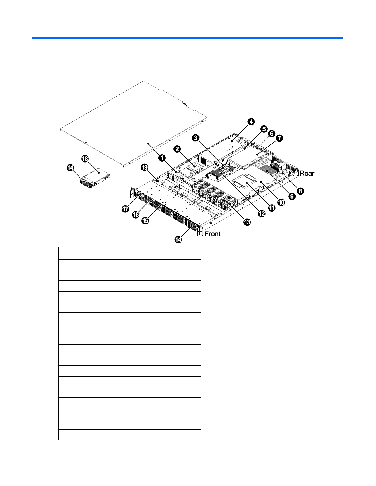
Component identification
Item
Description
1
1U chassis & access panel
2
Super cap and BBU for HBA card
3
System board
4
Fixed power supply
5
Add on card (FHHL)
6
OCP mezzanine card (10G SFP+ port) (2)
7
Riser card (1U slot)
8
DDR4 DIMM (16)
9
CPU (2)
10
Air baffle
11
Heat sink (2)
12
SASmezzanine card
13
System fan (40x40x56mm) (5)
14
2.5” HDD carrier (8)
15
2.5” fixed SSD
16
Asset tag and HDD sequence label
17
Front control panel
Component identification 7
Page 8
Item
Description
18
2.5” HDD (8)
19
HDD backplane
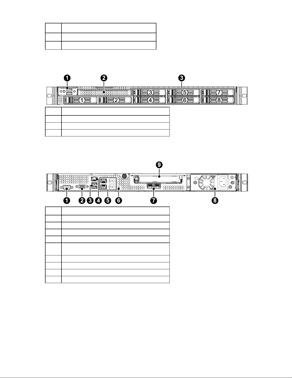
Item
Description
1
Front panel
2
SSD module
3
2.5” SAS/SATA HDD carriers (8)
Item
Description
1
COM
2
VGA
3
USB 2.0 (2)
4
RJ45 (10M/100M)
5
RJ45 x 4 (SKUA: 0, SKUB: 4, SKUC&D: 2)
(10M/100M/1000M)
6
UID button
7
10Gb SFP+ (optional)
8
Power supply unit
9
PCIe card
Front panel components
Rear panel components
Component identification 8
Page 9
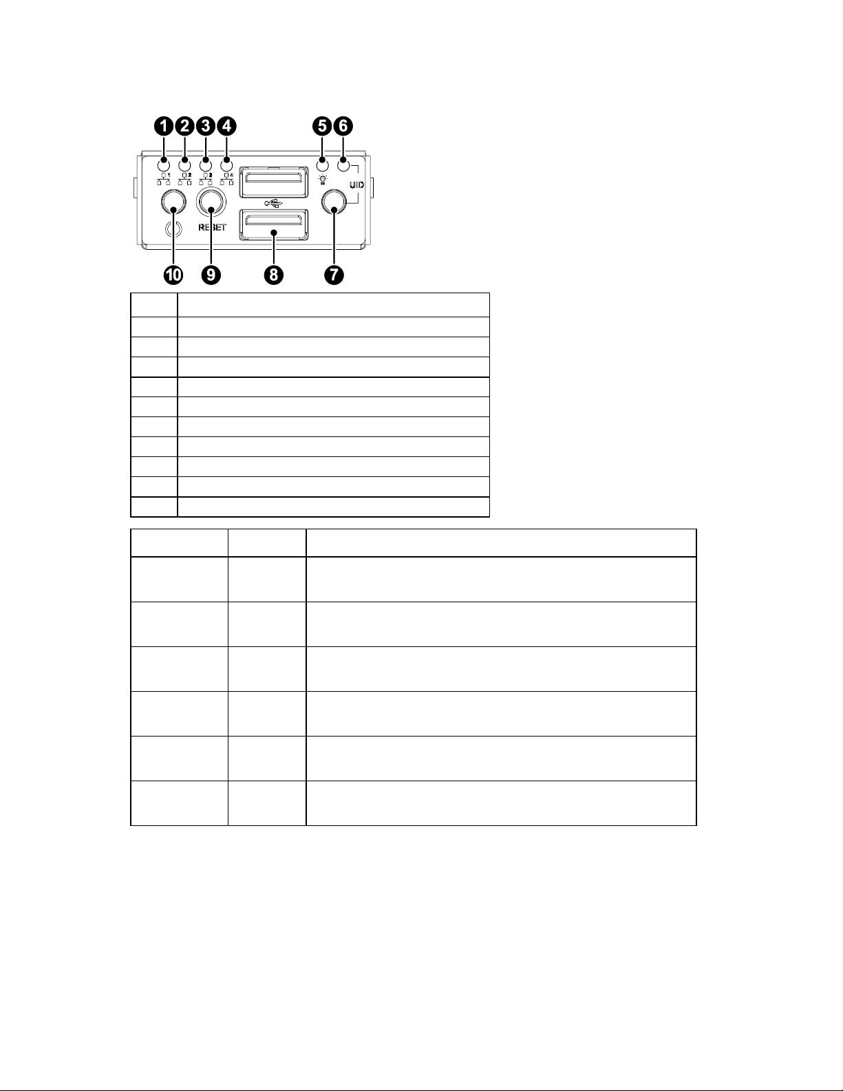
Front l panel LEDs and buttons
Item
Description
1
LAN 1 LED
2
LAN2 LED
3
LAN 3LED
4
LAN 4 LED
5
Power LED
6
UID LED
7
UID button
USB 2.0 ports
9
Reset button
10
Power button
LED Indicator
LED Color
Description
UID LED
Blue
On: System identified
Off: System not identified
LAN 1 Activity
LED
Green
Flashing: LAN1 data transfer
Off: LAN 1 no data transfer
LAN 2 Activity
LED
Green
Flashing: LAN 2 data transfer
Off: LAN 2 no data transfer
LAN 3 Activity
LED
Green
Flashing: LAN 3 data transfer
Off: LAN 3 no data transfer
LAN 4 Activity
LED
Green
Flashing: LAN 4 data transfer
Off: LAN 4 no data transfer
Power LED
Green
On: System powered up
Off: System powered down or in standby mode
Power supply LEDs
The 650W power supply comes with one LED and the LED is visible from the rear of the power supply.
Component identification 9
Page 10
LED Indicator
LED Color
Description
AC Power
Green
Off: No AC power to power supply
6.7Hz flashing: Power supply critical event causing a shutdown:
failure, OCP, OVP, fan fail
1Hz flashing: AC present/only 5VSB on (PS off)
On: Output ON and OK
LED Indicator
LED Color
Description
Activity LED
Blue
On: HDD Present without data transfer
Flashing: HDD data transfer
Off: HDD no power or not present
Fault LED
Red
On: HDD broken or Raid broken
Flashing: HDD Raid rebuilding
Off: HDD working well
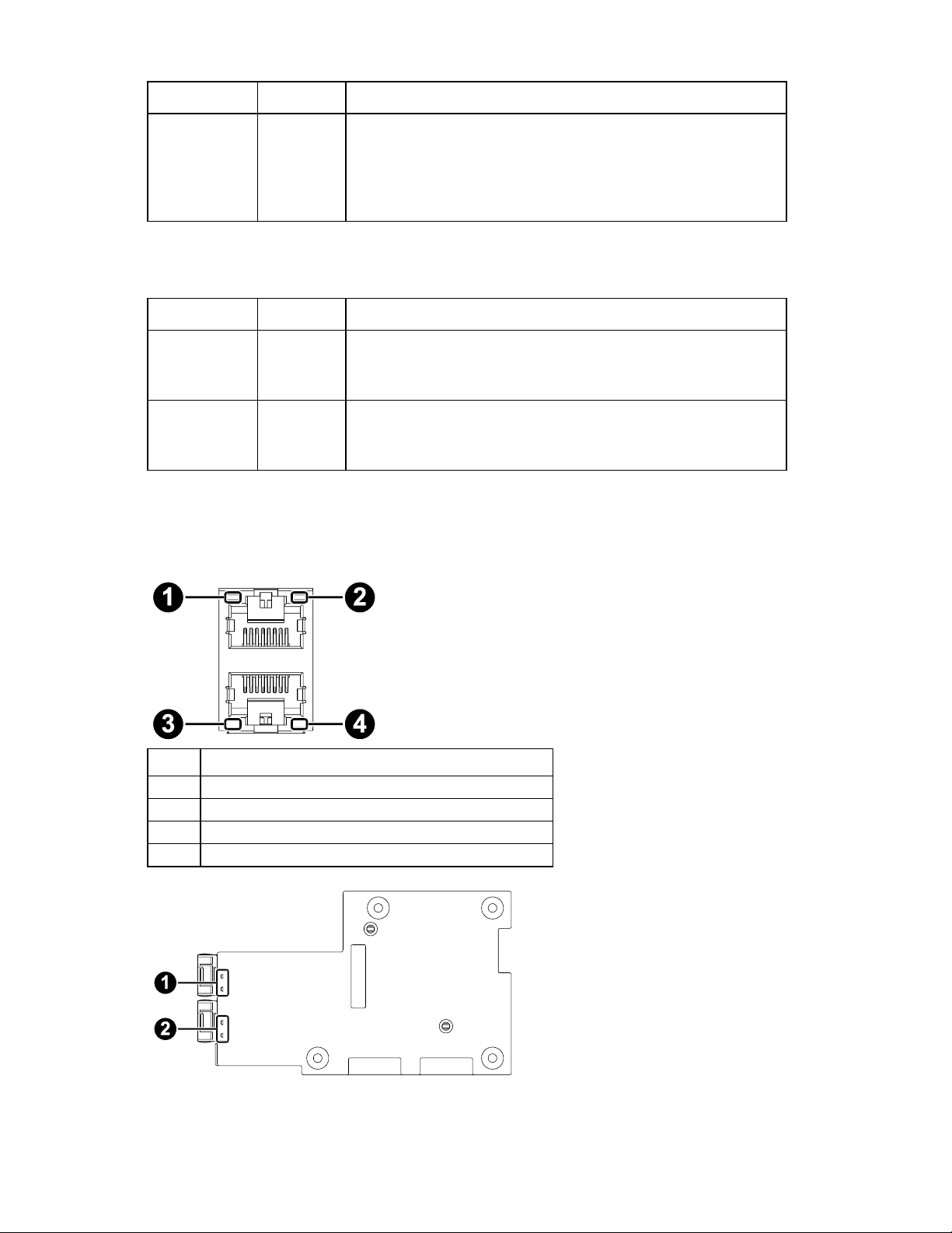
Item
Description
1
LAN 2&4 Link Speed LED
2
LAN 2&4 Link/Activity LED
3
LAN 1&3 Link Speed LED
4
LAN 1&3 Link/Activity LED
Storage drive LEDs
Board LEDs
See the following illustration to locate the LED indicator for RJ45, SFP+ and PHY (Management network).
Component identification 10
Page 11
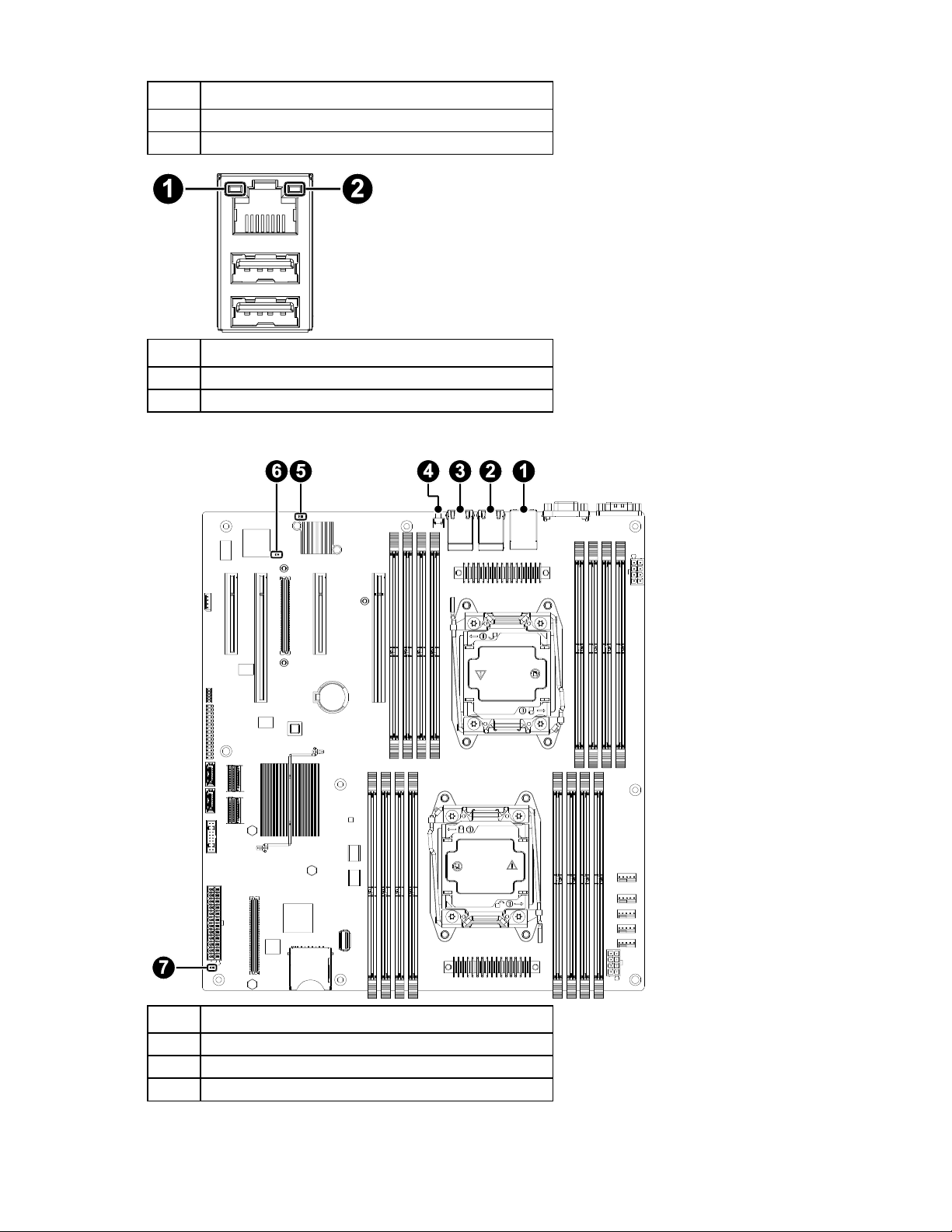
Item
Description
1
10G SFP+ Up LED
2
10G SFP+ Down LED
Item
Description
1
PHY Left LED
2
PHY Right LED
Item
Description
1
PHY LED
2
LAN LED
3
LAN LED
See the following illustration to locate the system board LED indicator:
Component identification 11
Page 12
Item
Description
4
UID LED
5
System Status LED
6
BMC_HEARTBEAT_LED
7
Standby LED
LED Name
Voltage
Sources
LED Color State
Description
STBY_LED
P5V_STBY
Green
On
AC On
Off
AC Off
UID LED
P5V_STBY
Blue
On
Unit selected for identification
Off
Unit not selected
SYS LED
P3V3_AUX
Green
On
System health OK
Yellow
On
Error occurred
BMC Heartbeat
LED
P3V3_AUX
Green
Flashing
BMC is ready
Off
BMC is not ready
LAN_0-1,
LAN_2-3
P3V3_AUX
Green (Right)
On
LAN link up but no activity
Green (Right)
Flashing
LAN link up and activity
(Right)
Off
LAN link down
Green (Left)
On
Green, link speed is 1000Mbps
Orange (Left)
On
Amber, link speed is 100Mbps
(Left)
Off
Off, link speed is 10Mbps
MGNT LAN LED
P3V3_AUX
Orange (Left)
On
Amber, link speed is 100/10Mbps
Green (Right)
Flashing
LAN link up and activity
Green (Right) and
Orange (Left)
Off and On
LAN link up but no activity
Green (Right) and
Orange (Left)
Off and Off
Disconnected
Component identification 12
Page 13
System board components
Item
Description
1
8pin Processor1 power
2
DIMM slot (16)
3
Processor1
4
Processor0
5
Fan header (5)
6
8pin Processor0 power
7
MiniSAS connector (2)
8
SAS mezzanine connector
9
24pin main power
10
Front USB connector
11
SATA3.0 (SATA DOM)
12
SATA3.0
13
Front control connector
14
OCP mezzanine card slot
15
PCIe slot (3), PCIe slot (1) (optional with OCP mezzanine)
16
UID switch
17
RJ45 x 4 (SKUA: 0, SKUB: 4, SKUC&D: 2)
18
RJ45 and USB 2.0 x 2
19
VGA
20
COM
Component identification 13
Page 14
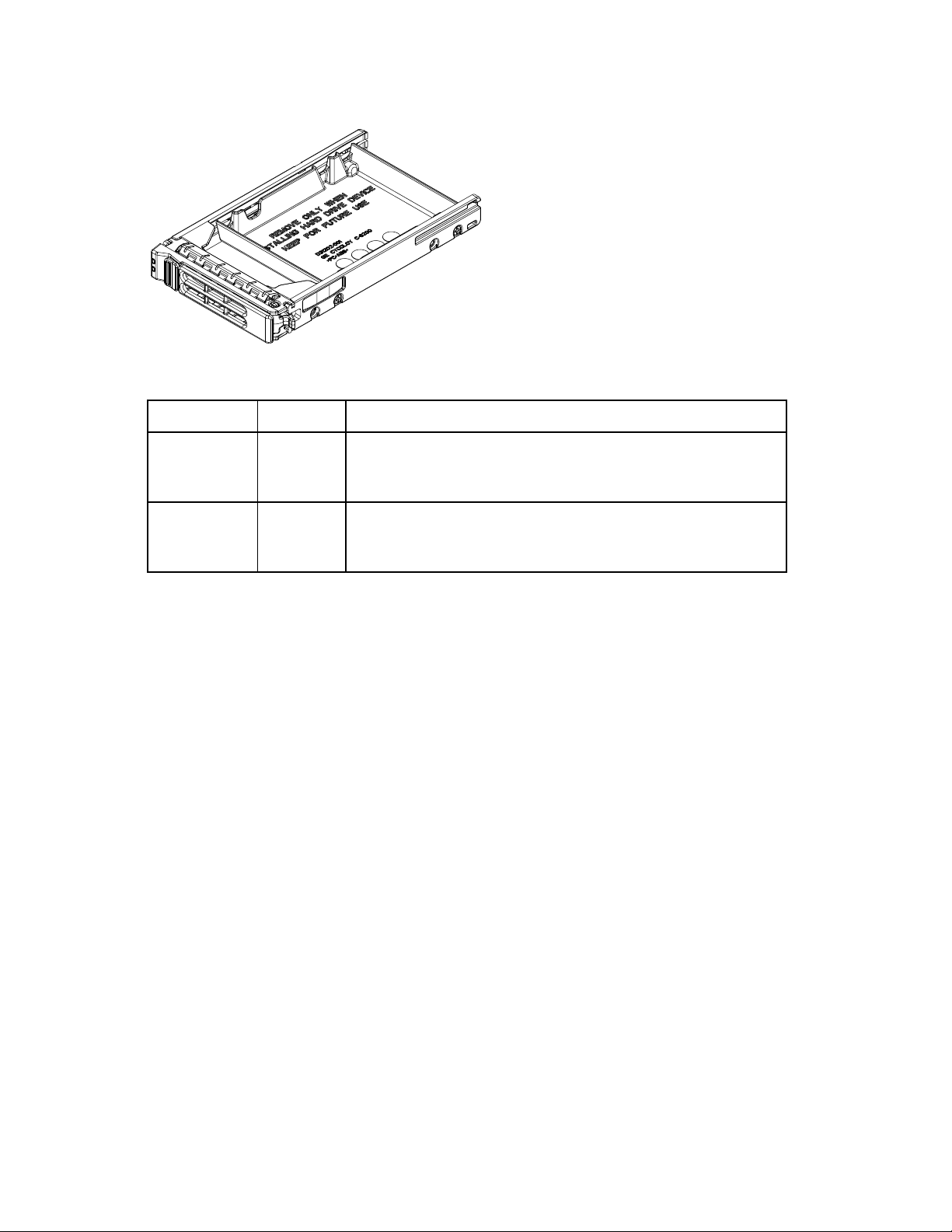
HDD carrier LED definitions
LED Indicator
LED Color
Description
Activity LED
Blue
On: HDD Present without data transfer
Flashing: HDD data transfer
Off: HDD no power or not present
Fault LED
Red
On: HDD broken or Raid broken
Flashing: HDD Raid rebuilding
Off: HDD working well
Each drive tray supports two light pipes to direct light from the drive status LEDs on the backplane to the
face of the tray, allowing it to be viewable from the front of the system.
Important: The fault LED function is only supported when a HBA/RAID card is installed.
Component identification 14
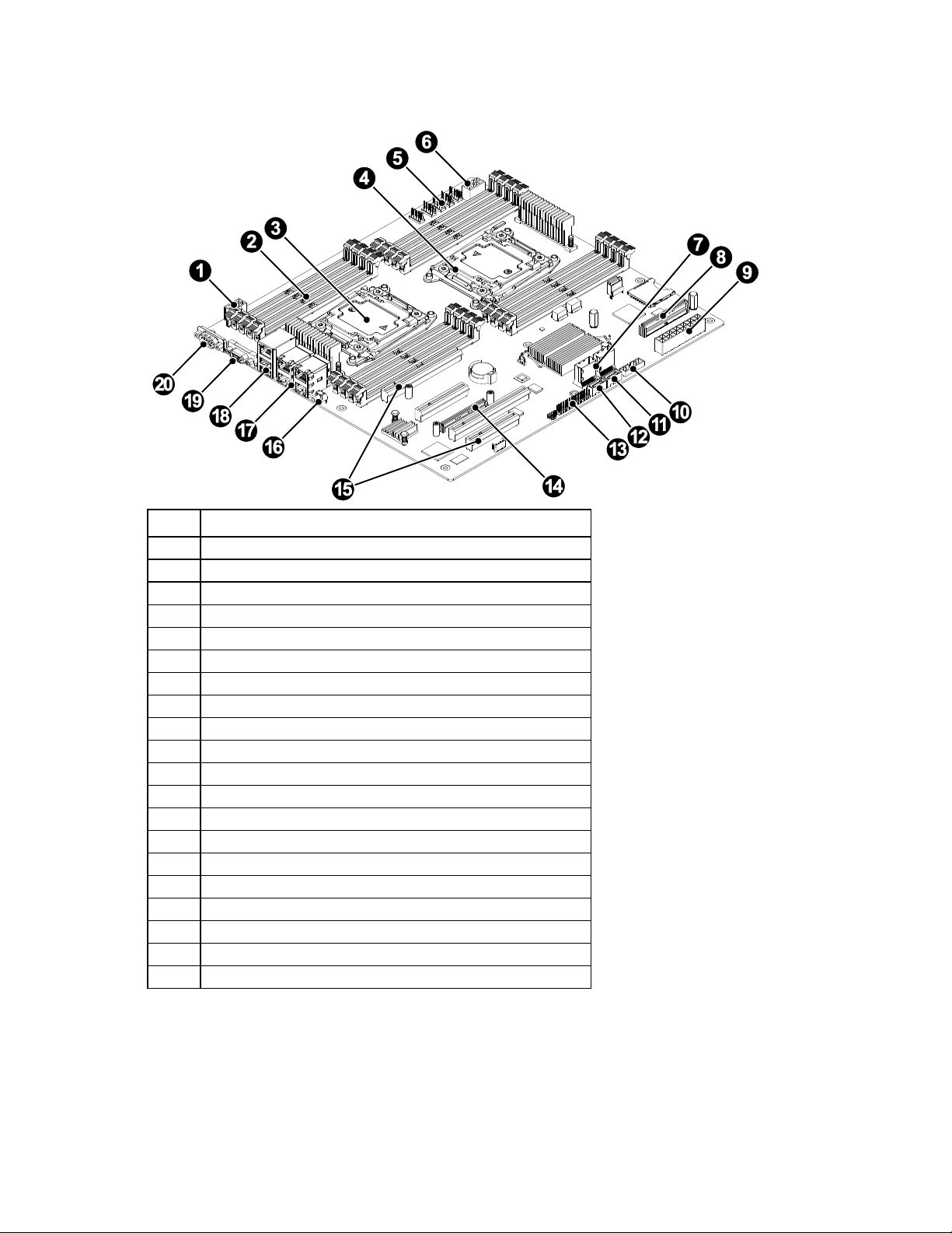
Page 15
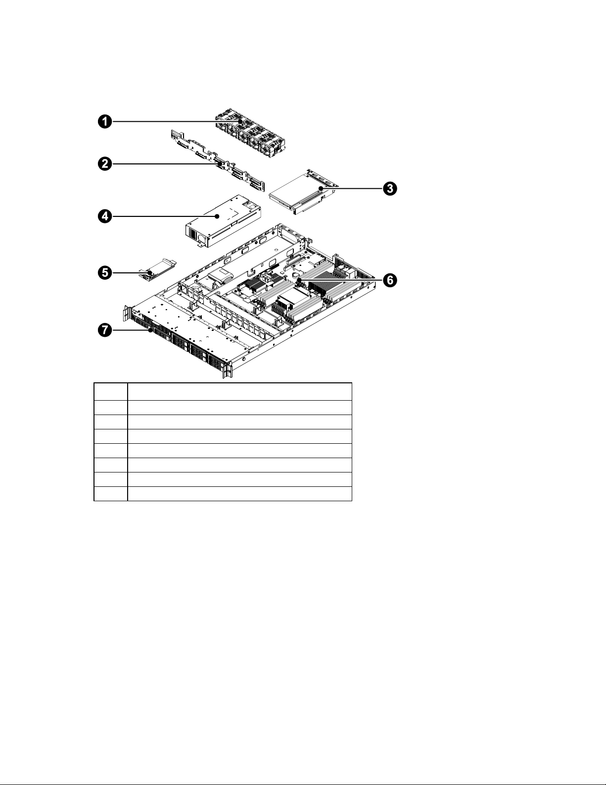
System components
Item
Description
1
System fan (40x40x56mm) (5)
2
HDD backplane
3
Riser rard (1U slot)
4
Fixed power supply
5
Front control panel
6
System board
7
2.5” HDD (8)
The following figure shows specific components of the server system. See the following figure and table to
become familiar with the server components.
Component identification 15
Page 16

Operations
CAUTION: All applications and files will be closed without saving changes, file system
corruption might occur.
Powering up the server
The following procedure assumes that at least one power cord is connected to the server to supply power
to the server and that the server has been previously powered on.
1. Verify the power cord, power supply LED indicator, and power LED indicator on front control panel.
Turn the power supply LED on immediately to indicate the power is being supplied to the power
supply and the system in the standby power state. Power LED off to indicate the server is not powered
on or has been powered off in standby mode.
2. Power up the server
o Local server power-on: Press and release the power button on the front control panel of the server
to power on the server.
o BMC web interface power-on: Log in to the BMC web interface and select power on from the
power control action list box.
o Log in to the BMC CLI and execute the IPMI command to power on system.
Powering down the server
The following procedures show how to shut down the server and verify the power status.
Shutting down the server
Graceful shutdown
To perform a graceful shutdown: Save all open files, network service, and close all applications prior
to shut down.
Stop or terminate all necessary system processes to bring down the operating system and power off
the compute node.
Press and release the power button on the front panel of ACPI-enabled (Advanced Configuration and
Power Interface) operating systems to perform an orderly shutdown of the operating system. Servers
not running ACPI-enabled operating systems will shut down immediately.
Emergency shutdown
To perform an emergency shutdown, press and hold down the power button on the front panel for at least
five seconds to shut down and enter standby power mode.
BMC CLI shutdown
Log in to the BMC and execute the IPMI command to shut down the server.
Operations 16
Page 17

Verifying the power status
Verify all power LED indicators of the server and make sure the power LED light is off before replacing and
removing the server components from the rack.
Operations 17
Page 18

Installation
Safety measures
Static electricity discharges can damage computer components and electronic circuit boards. Working on
computers that are still connected to a power supply can be extremely dangerous. Follow these guidelines
to avoid self-injury and damage to the computer:
Always disconnect the server from the power outlet when working inside of the computer case.
If possible, wear a grounded wrist strap when working inside the computer case. Alternatively,
discharge any static electricity by touching the bare metal chassis of the computer case, or the bare
metal body of any other grounded appliance.
Hold electronic circuit boards only by the edges. Do not touch the components on the board unless it
is necessary to do so. Do not flex or stress the circuit board.
Leave all components inside the static-proof packaging until ready to use the component for the
installation.
Identifying the contents of the server shipping carton
Unpack the server shipping carton and locate the materials for installing the server.
The contents of the server shipping carton include:
Server
Power cord (optional)
Rack-mounting hardware (optional)
In addition to the supplied items, you might need:
Operating system or application software
Hardware options
Installation 18
Page 19
Hard disk drives
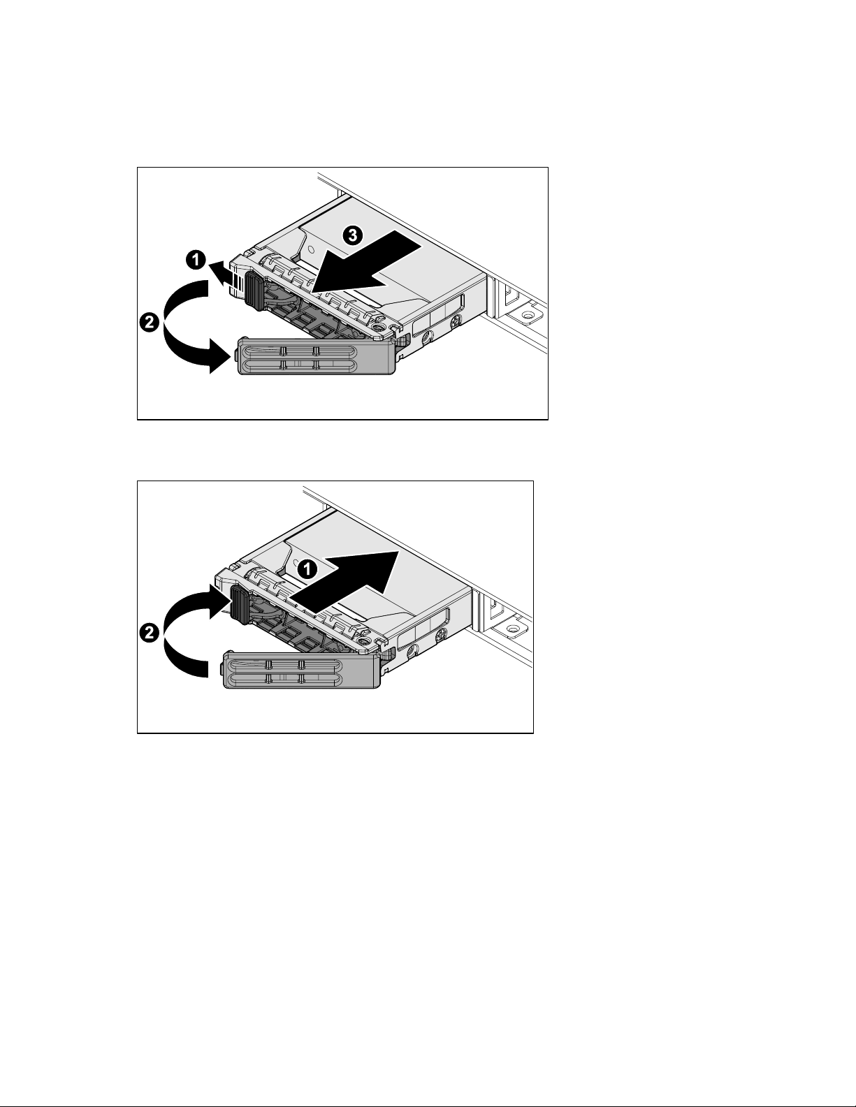
Removing the hot-swappable HDD assembly
Installing the hot-swappable hard disk drive assembly
Removing the hard disk drive module
To remove the HDD module:
1. Remove the hot-swap HDDs assembly (on page 19).
2. Remove the screws securing the HDD from the HDD carrier.
3. Remove the HDD from the HDD carrier.
Installation 19
Page 20
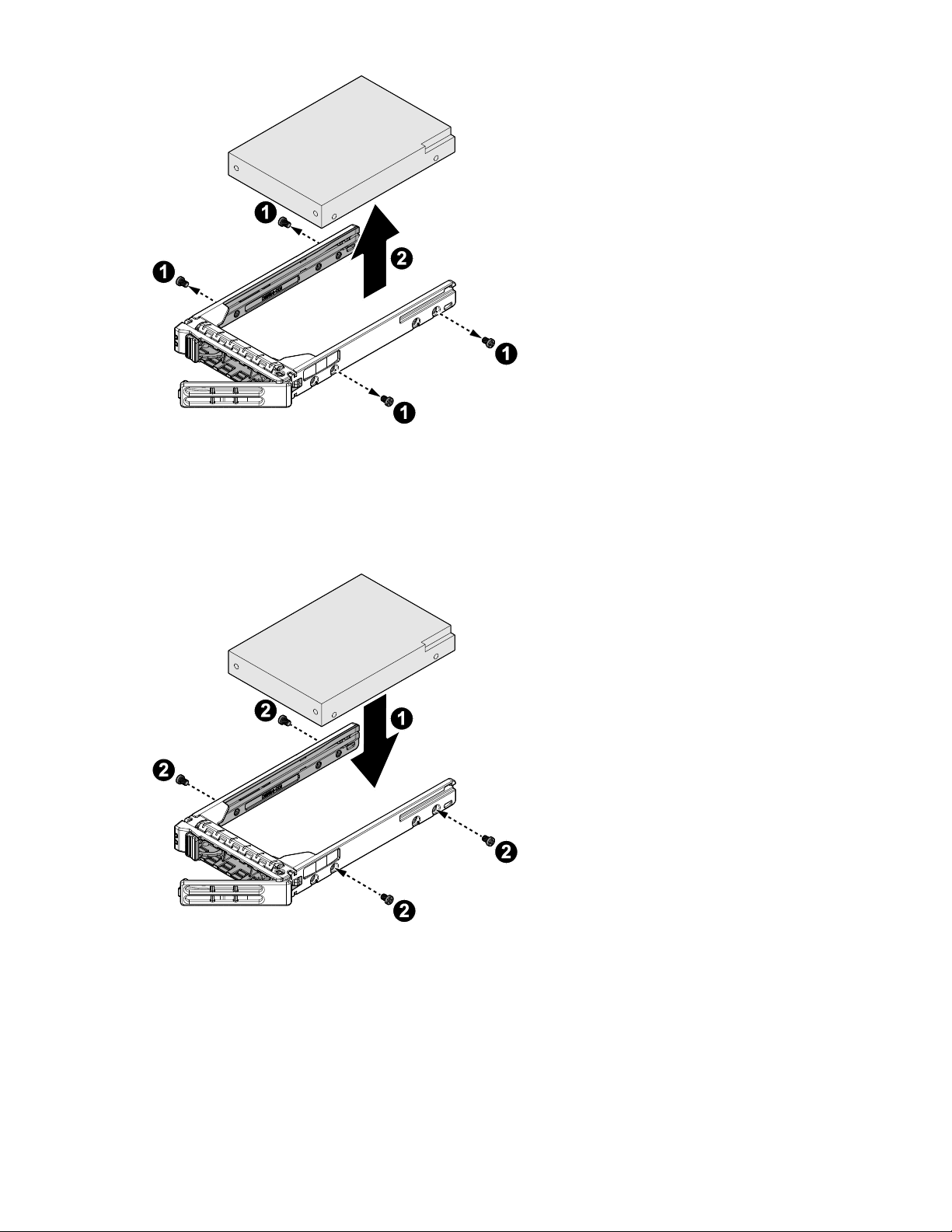
Installing the HDD module
To install the HDD module:
1. Align the HDD in the HDD carrier, connectors facing the opening of the carrier.
2. Secure the HDD and the HDD carrier with the screws.
3. Install the hot-swap HDDs assembly (on page 19).
Power supply unit (PSU)
Removing the PSU
To remove the power supply unit:
Installation 20
Page 21
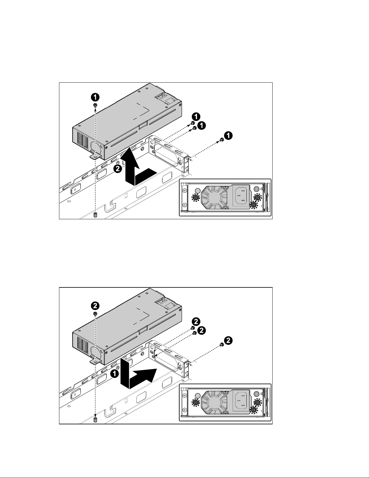
1. Power down the server, and then detach all power cords from the power supplies.
2. Remove the access panel (on page 37).
3. Locate the PSU and remove the cabling attached to the system board and components.
4. Remove the screws to release the PSU from the chassis.
5. Slide the PSU out to remove it.
Installing the PSU
To install the power supply unit:
1. Align the PSU on the chassis and install in place.
2. Secure the PSU with the screws.
3. Connect the cabling to the system board and the PSU.
Installation 21
Page 22
4. Install the access panel (on page 38).
Expander board
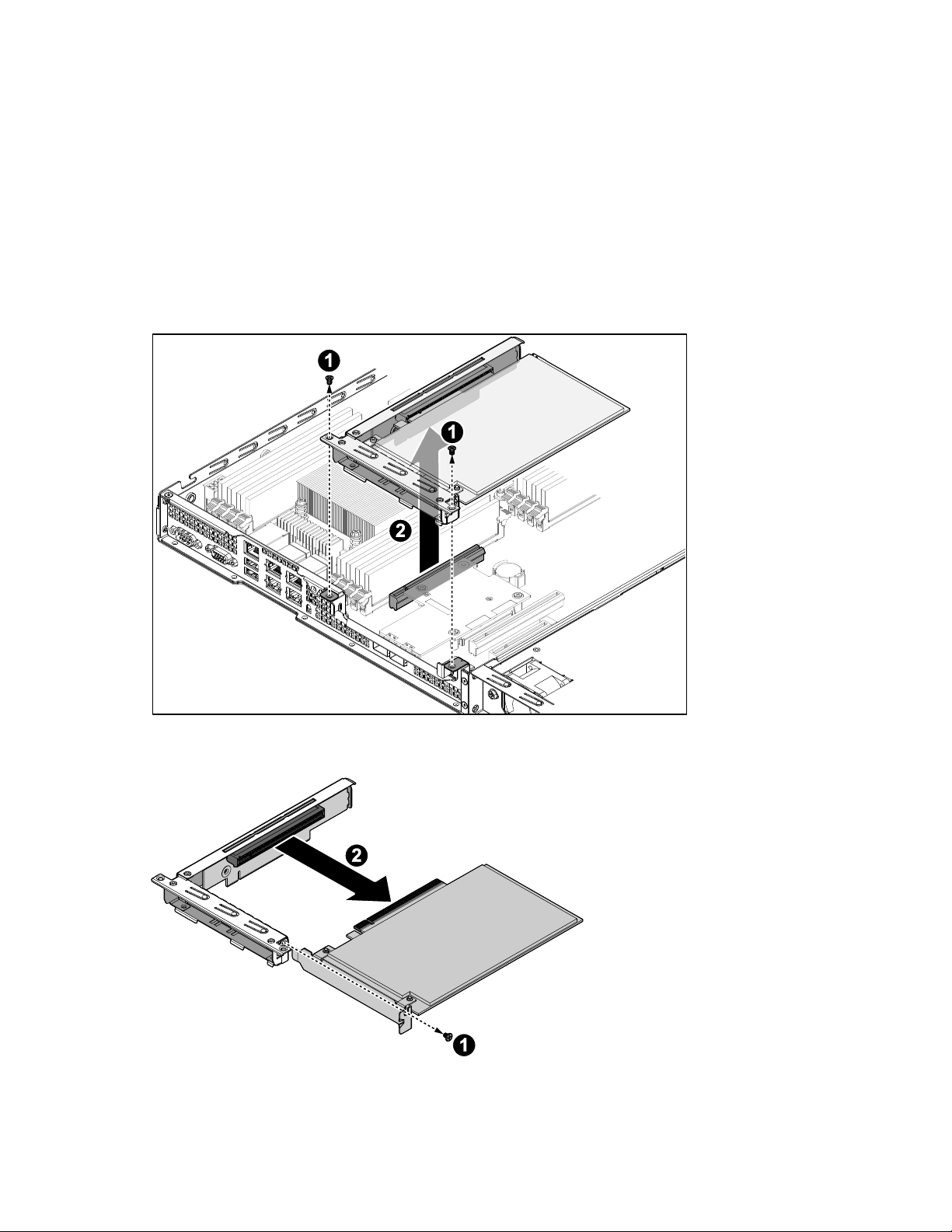
Removing the expander board
To remove the expander board:
1. Power down the server and detach all power cords from the power supplies.
2. Remove the access panel (on page 37).
3. Remove the PCIe assembly from the chassis.
4. Disconnect the PCIe card from the riser card.
5. Remove the PCIe card.
Installation 22
Page 23
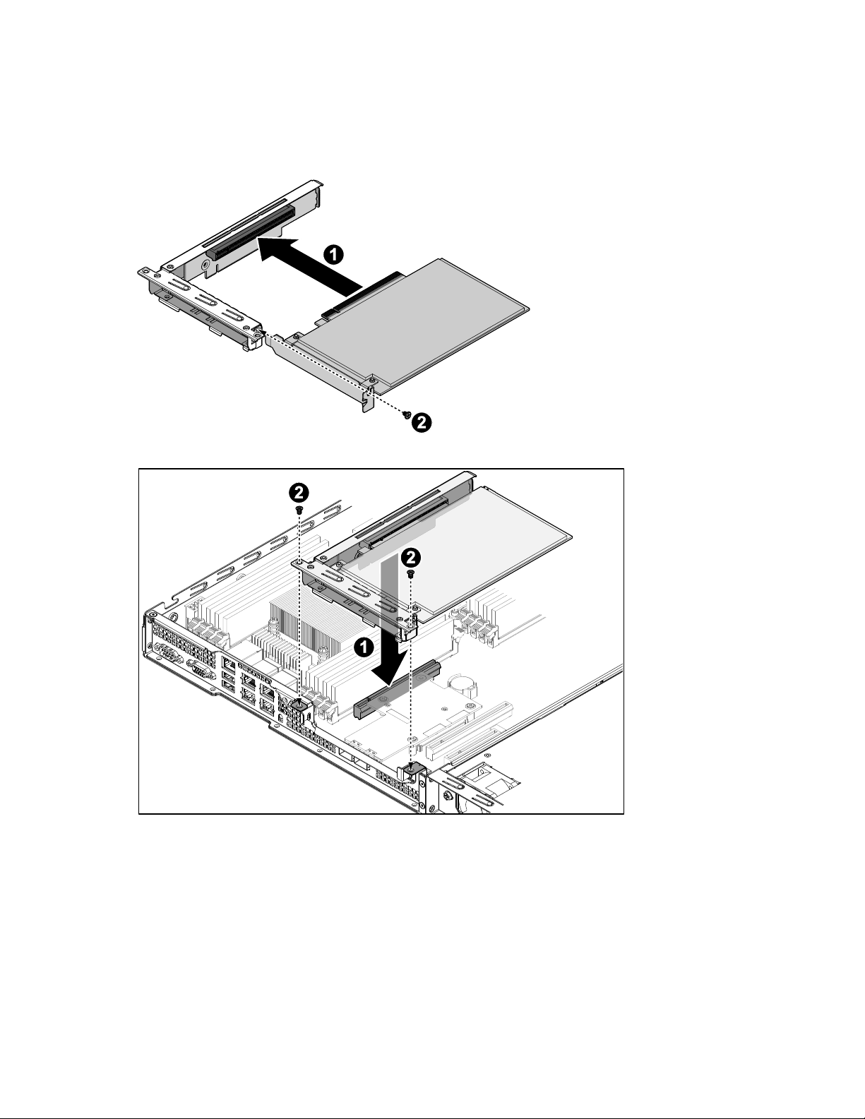
Installing the expander board
To install the hard expander board:
1. Orient the PCIe card with the riser guide slot and push in the direction of the arrow until the PCIe card
is secured in the PCIe card connector.
2. Install the PCIe assembly. Press down gently to seat it in place.
3. Install the access panel (on page 38).
Hard disk drive backplane
Removing the hard disk drive backplane
To remove the HDD backplane:
1. Power down the server and detach all of the power cords from the power supplies.
Installation 23
Page 24
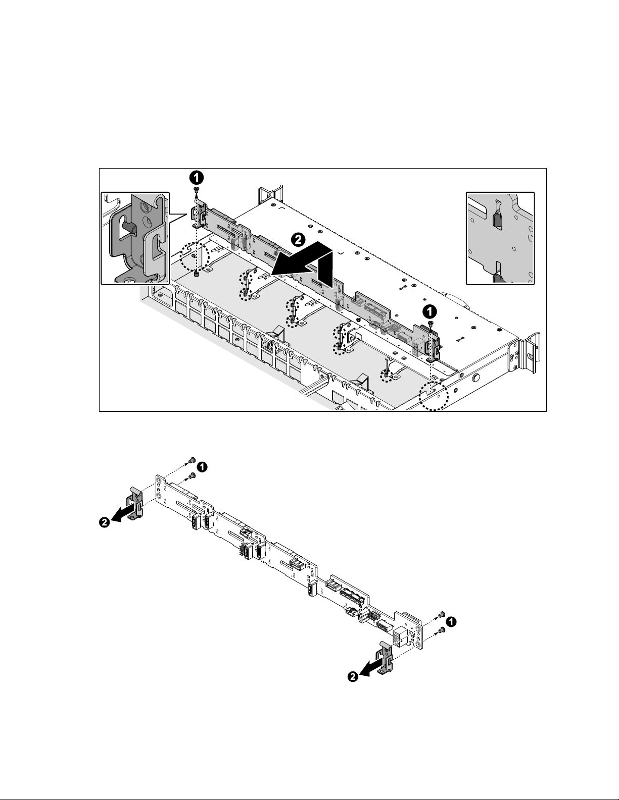
2. Remove the access panel (on page 37).
3. Remove all the hot-swappable HDDs assemblies (on page 19).
4. Remove the front control board (on page 38).
5. Disconnect all the cables from the HDD backplane.
6. Remove the screws securing the HDD backplane assembly to the chassis.
7. Release the HDD backplane assembly from the guide tabs on the chassis, and then remove the HDD
backplane.
8. Remove the screws securing the HDD backplane to the HDD assembly bracket (1).
9. Remove the HDD backplane (2).
Installation 24
Page 25
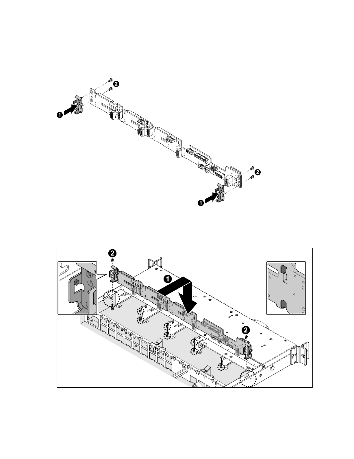
Installing the HDD backplane
To install the HDD backplane:
1. Align the screw holes on the HDD backplane with the screw holes on HDD assembly bracket. (1)
2. Secure the HDD backplane and HDD assembly bracket with the screws. (2)
3. Align the screw holes on the HDD backplane assembly with the screw holes on the chassis, the HDD
SAS connectors must face inward.
4. Install the HDD backplane assembly to the guide tabs on the chassis.
5. Secure the HDD backplane assembly and the chassis with the screws.
6. Connect all the cables to the HDD backplane assembly.
7. Install the front control board (on page 39).
Installation 25
Page 26
8. Install all the hot-swappable HDDs assemblies (obpage 19).
9. Install the access panel (on page 38).
System fans
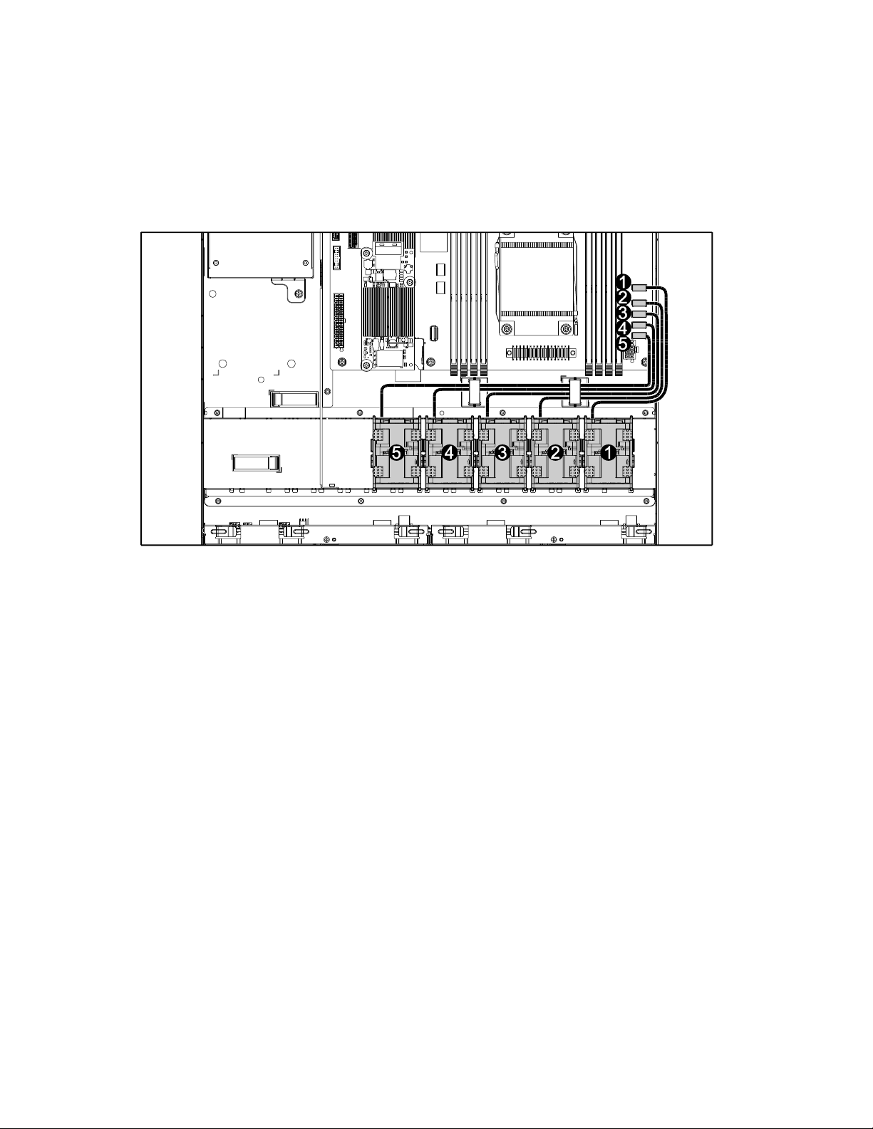
Cable routing
Removing the system fan assembly
To remove a system fan assembly:
1. Power down the server and detach all of the power cords from the power supplies.
2. Remove the access panel (on page 37).
3. Disconnect the five (5) fan cables from the system board. See page 13 for location.
4. Remove the fan module.
Installation 26
Page 27
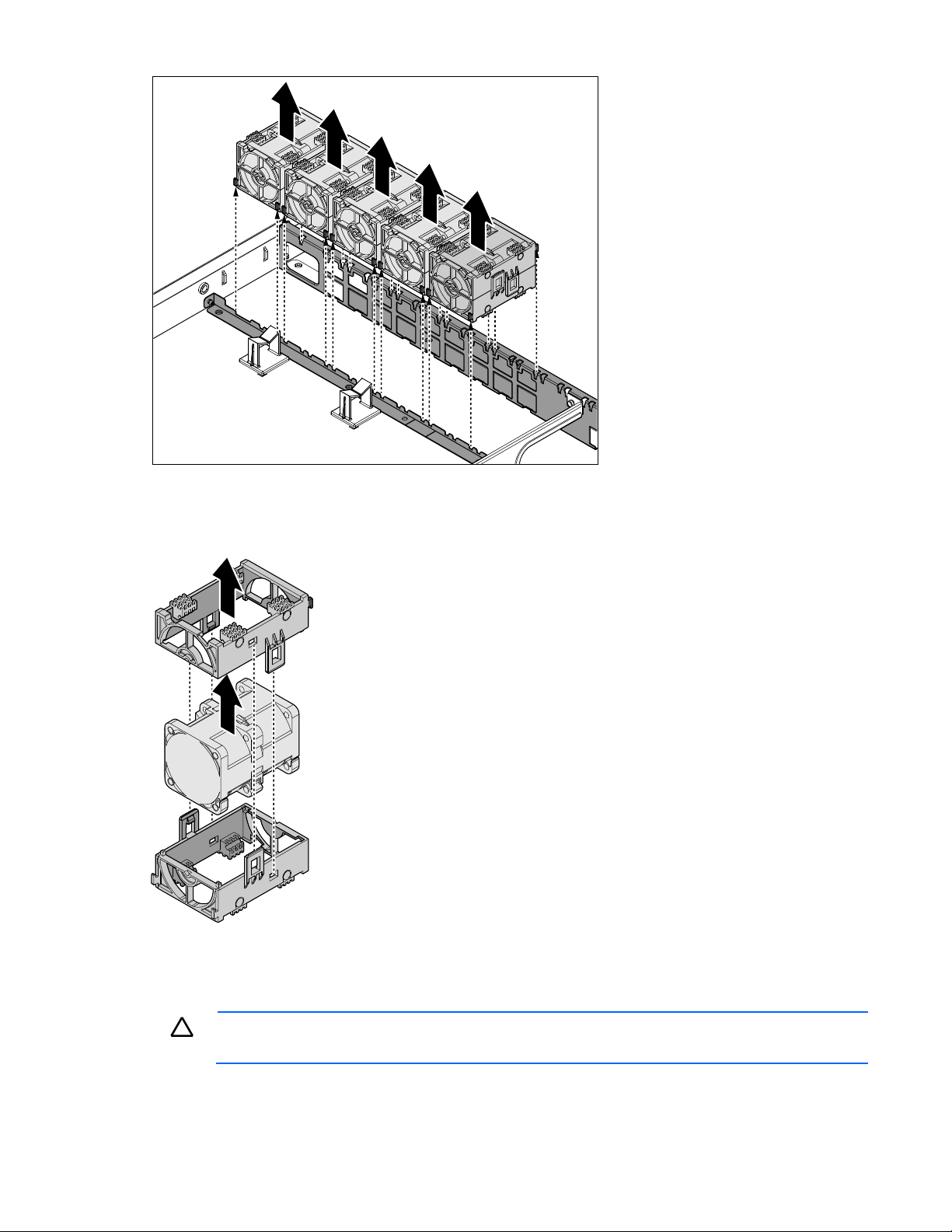
5. Unlock the fan assembly bracket.
CAUTION: Make sure the airflow arrows on the system fan are pointing towards the rear of
the system to prevent system overheating.
6. Remove the upper fan assembly bracket.
7. Remove the fan.
8. Repeat the procedure for the remaining fans.
Installing the system fan assembly
To install the system fan assembly:
Installation 27
Page 28
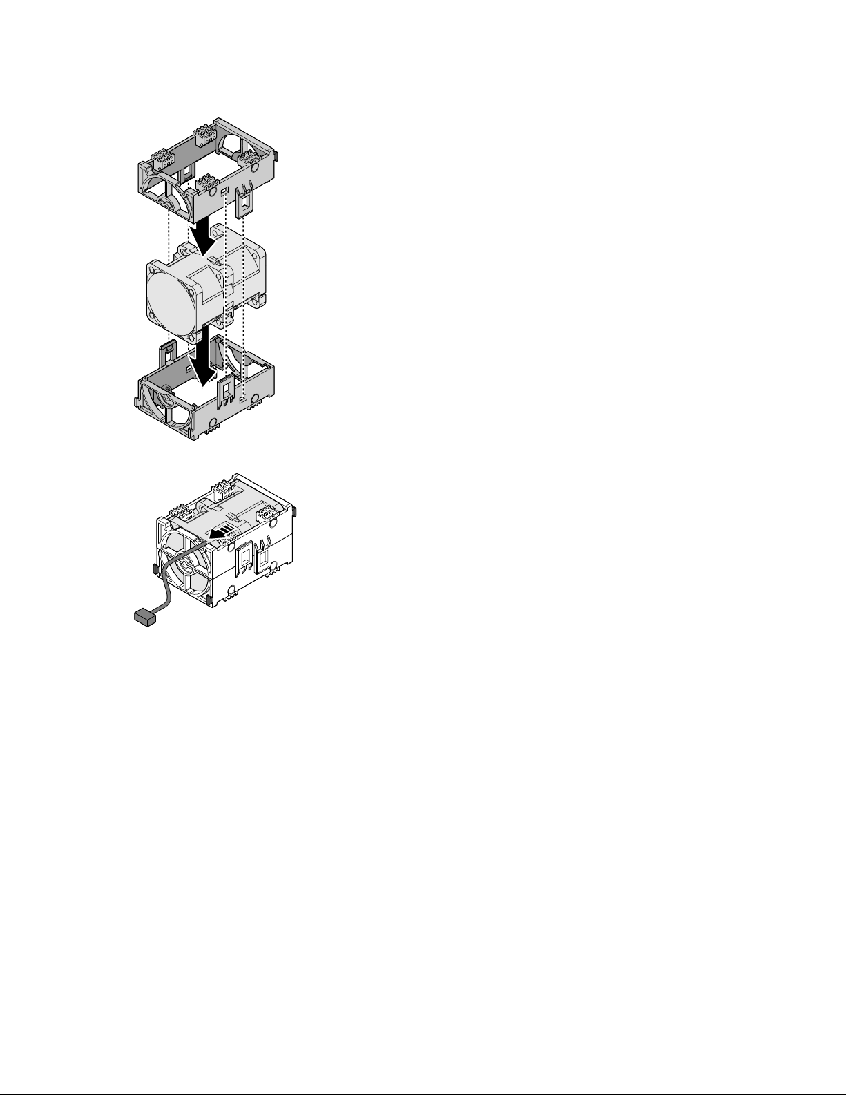
1. Install the fan into the lower fan assembly bracket.
2. Install the upper fan assembly bracket and lock it.
3. Guide the fan cable through the gap in the upper bracket.
4. Align the fan assembly with the chassis and fan cable facing the rear of the chassis.
5. Install the fan assembly into the chassis.
Installation 28
Page 29
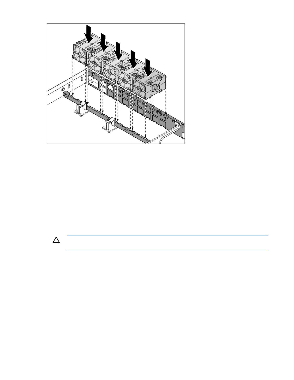
6. Repeat the procedure for the remaining fans.
CAUTION: If only one processor is installed, only one heat sink needs to be installed.
A CPU0 heat sink is different than a CPU1 heat sink.
7. Connect the five (5) fan cables to the system board. See page 13 for location.
8. Install the access panel (on page 38).
Heat sinks
Passive heat sinks cool processors. To achieve optimal cooling performance, the underside of the heat sink
must be properly attached to the processor with TIM. The mechanical performance of the heat sink is
designed to meet the requirements of Intel processors. The heat sink is necessary to maintain chipset
temperature at or below temperature limits.
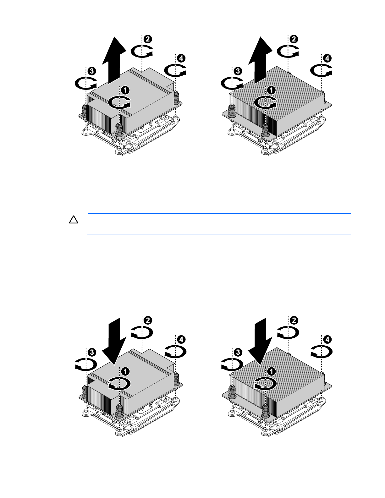
Removing the heat sink
To remove the heat sink:
1. Power down the server and then detach all power cords from the power supplies.
2. Remove the access panel (on page 37).
3. Loosen the four screws in the order shown.
Installation 29
Page 30
Processor0
Processor1
4. Remove the heat sink.
CAUTION: Do not apply an excessive amount of thermal compound to prevent damage to the
system board.
Processor0
Processor1
5. Repeat the procedure for the additional heat sink.
Installing the heat sink
To install the heat sink
1. Make sure the top of the processor is clean.
2. Apply a small drop of thermal compound in the middle of the processor.
3. Remove the protective cover from the underside of the heat sink.
4. Align the heat sink so the sticker label faces the DIMM module.
5. Place the heat sink on top of the processor until it is seated firmly in place.
6. To secure the heat sink, tighten the four retaining screws clockwise, in the order shown.
Installation 30
Page 31

7. Repeat the procedure for the additional heat sink.
CAUTION: In a single processor configuration, the single processor must be installed in the
Processor0 socket (see page 13 for location).
ESD protection must be worn during the procedure to avoid damaging the components.
8. Install the access panel (on page 38).
Processor
Removing the processor
To remove the processor:
1. Power down the server and detach all of the power cords from the power supplies.
2. Remove the access panel (on page 37).
3. Remove the heat sink (on page 29).
4. Press downward and inward on the right processor locking lever to release it.
5. Press downward and inward on the left processor locking lever, pulling it fully open.
6. Lift the processor load plate to the fully open position.
Installation 31
Page 32

7. Lift the processor out of the socket.
CAUTION: ESD protection must be worn during the procedure to avoid damaging the
components.
8. Repeat the procedure for the additional processor.
Installing the processor
To install the processor:
1. Align the gold triangle identifying pin 1 of the processor with the triangular cutout of the socket and
the key-indent on the socket.
2. Insert the processor into the socket, and make sure that the four keys on the socket fit into the
corresponding keys on the processor.
Installation 32
Page 33

3. Lower the processor load plate over the processor.
4. Push the left processor locking lever down (1), and then latch it into the locked position (2). The
protective plastic cover pops out as the latch is engaged.
5. Push the right processor locking lever down and latch it into the locked position (3).
6. Repeat the procedure for the additional processor.
7. Install the heat sink (on page 30).
8. Install the access panel (on page 38).
Installation 33
Page 34

DIMM modules
DIMM: Max x16pcs DIMM
Removing the DIMM module
The system board includes 16 (four DIMM channels per processor) DIMM slots for the installation of DDR4
1600/1866/2133 MHz DIMMs.
To remove the DIMM module:
1. Power down the server, and then detach all power cords from the power supplies.
2. Remove the access panel (on page 37).
3. Push the locking latches of the DIMM slot downward and outward to eject the DIMM module.
4. Remove the DIMM module.
Installation 34
Page 35

Installing the DIMM module
CAUTION: When removing any component, wear a properly grounded static strap to prevent
static discharge.
The system board includes 16 (four DIMM channels per processor) DIMM slots for the installation of DDR4
1600/1866/2133 MHz DIMMs.
To install the DIMM module:
1. Pull the locking latches of the DIMM slot outward.
2. Place the DIMM module into the socket so the notch and obstruction are aligned.
3. Press the edge connector of the DIMM module into the slot. Press down firmly so that the locking
latches of the DIMM slot are levered upwards to secure the DIMM module.
4. Install the access panel (on page 38).
System board module
Removing the system module
To remove the system board module:
1. Power down the server and detach all power cords from the power supplies.
2. Remove the access panel (on page 37).
3. Remove the DIMM modules (on page 34).
4. Remove the heat sinks (on page 29).
5. Remove the processors (on page 31).
6. Disconnect all of the cables from the system board.
7. Remove the screws from the system board module.
8. Lift the front of the system board and pull it away from the rear of the system. Make sure the I/O ports
clear the chassis before lifting the system board.
9. Remove the system board module.
Installation 35
Page 36

CAUTION: When removing any component, wear a properly grounded static strap to prevent
static discharge.
Installing the system board module
To install the system board module:
1. Align the I/O ports on the system board with the slots on the chassis.
2. Slide the system board into position. Make sure the I/O ports are seated correctly.
3. Lower the system board onto the chassis. Make sure the screw holes on the system board and chassis
are aligned.
4. Secure the system board module to the chassis with the screws.
Installation 36
Page 37

CAUTION: Be sure that the server is powered down and the AC power cords are
disconnected from the server power supplies to avoid personal injury or server damage.
5. Connect the cables.
6. Install the processors (on page 32).
7. Install the heat sinks (on page 30).
8. Install the DIMM modules (on page 35).
9. Install the access panel (on page 38).
Access panel
Removing the access panel
Installation 37
Page 38

Installing the access panel
Front control board
Removing the front control board
To remove the front control board:
1. Power down the server and detach all of the power cords from the power supplies.
2. Remove the screw from the top of the chassis.
3. Slide the front control board out of the chassis.
Installation 38
Page 39

Installing the front control board
To install the front control board:
1. Slide the front control board into the chassis.
2. Secure the front control board to the chassis with the screw.
Riser card
Removing the riser card
To remove the riser card:
Installation 39
Page 40

1. Power down the server and detach all of the power cords from the power supplies.
2. Remove the access panel (on page 37).
3. Disconnect the riser assembly from the system board.
4. Remove the screw securing the riser card to the riser bracket.
5. Remove the riser card from the riser bracket.
Installing the riser card
To install the riser card:
1. Align the screw holes on the riser card with the screw holes on the riser bracket.
2. Secure the riser card to the riser bracket with the screw.
Installation 40
Page 41

3. Align the connector on riser assembly with the connector on the system board.
4. Attach the riser assembly. Press down gently to seat in place.
5. Install the access panel (on page 38).
Powering on and selecting boot options
1. Connect the Ethernet cable.
2. Press Power On/Standby.
3. During the initial boot:
o To modify the BIOS default settings, press F2 or DEL when prompted from the start-up sequence to
enter the BIOS setup utility. By default, the BIOS setup utility runs in the English language.
o It is not necessary to modify the server configuration, press F7 during system boot to select the
boot device for system software installation.
o To enter PXE boot, press F12 during boot time when prompted from the start sequence.
Installing the operating system
To operate properly, the server must have a supported OS.
Installation 41
Page 42

To install an OS on the server, use one of the following methods:
Local installation (USB key or USB optical disc)
Remote deployment installation (PXE, virtual KVM)
Follow up install OS step and reboot system
Installation 42
Page 43

Cabling
Item
Description
Quantity
1
24 pin main power
1
from PSU
2&3
2x16 pin to 8 pin CPU1 &
8 pin CPU0 Power Y cable
1
from PSU
4
2x4 pin HDD BP power
cable from PSU
1
from PSU
Internal system cable routing
The server internal cable routing is listed in the following figure and table:
Cabling 43
Page 44

System Interconnection Signal (by PCH)
Item
Description
Quantity
1
System board (2x10 pin )
to F-USB board (2x5 pin)
Cable
1
from system board
to front USB board
2
System board (2x15 pin) to
FP (2x15 pin) cable
1
from system board
3
From onboard PCH to HDD
backplane cable
2
from onboard
MiniSAS
4
From system fan to system
board (1x5 pin) cable
5
from fan
5
From PSU to system board
PMBUS (1x5 pin) cable
1
from PSU
6
From system board SATA
to SSD cable
1
from system board
SATA
Cabling 44
Page 45

System Interconnection Signal (by 3rd RAID Card)
Item
Description
Quantity
1
System board (2x10 pin) to
F-USB board (2x5 pin)
cable
1
from system board
to front USB board
2
System board (2x15 pin) to
FP (2x15 pin) cable
1
from system board
3
From RAID card to HDD
backplane
2
from RAID card
MiniSAS
4
From system fan to system
board (1x5 pin) cable
5
from fan
5
From PSU to system board
PMBUS (1x5 pin) cable
1
from PSU
6
From system board SATA
to SSD cable
1
from system board
SATA
Cabling 45
Page 46

Configuration
BMC
Web GUI introduction
The web GUI is a friendly interface for the end users. A user can access the iBMC FW via a web browser,
and then go through the server status and do many configurations to the IBMC FW.
The default user privilege is set to administrator. The web function access rights are determined by different
privileges. For example, the administrator privilege can access all functions, but the user privilege cannot.
The web GUI provides many useful functions, such as:
firmware update
system power control
system event log (SEL)
current sensor reading
configuration for: BMC network, user accounts, serial, PEF, alerts, SOL, information about BMC, and
the system
IP address
Static and DHCP are the two common IP sources of iBMC FW. The default setting is DHCP. The detailed IP
address information is available from the BIOS setup menu.
User name and password
A user name and password are required to establish a web GUI session. The user should also have
accessibility to the LAN channel. Use the system management software to set the user name, password,
and grant access. The default setting is shown below:
ID 2: User Name = admin Password = Password1
Web browsers
iBMC FW supports either Microsoft Internet Explorer (Windows platform) or Firefox (Linux platform).
The embedded web serve provides full access. The web GUI is accessible via the HTTP protocol or via the
encrypted HTTPS protocol.
Logging in
To log in to the web GUI, enter the iBMC FW IP address into a web browser. An example of using the
HTTP protocol is http://10.141.104.176. An example of using the encrypted HTTPS protocol is
https://10.141.104.176
Configuration 46
Page 47

Updating the firmware
Many common problems can be resolved by updating the firmware. The BMC FW can be updated
through a host-based utility or through the web GUI.
Restoring the default configuration
The BMC FW supports an OEM command to restore all of the configuration values to their defaults. Using
the OEM command restores all IPMI configuration parameters and all Linux user configuration files
(password, group, and so on).. The OEM command is not available to the end user, but the web GUI
provides a friendly interface to do this. This command does not restore the SEL records.
BMC FW version
The “Get Device ID” command (NetFn Application, Command 1) reports the firmware revision. The
“Get Device ID” command also reports the auxiliary firmware revision.
The firmware build ID can map from the firmware revision. Naming convention of build ID is J2BTxxy. “xx”
is minor revision (BCD encoded), and “y” is auxiliary firmware revision. “y” is “a” if auxiliary firmware
revision is 0, and “y” is “b” if auxiliary firmware revision is 1, and so on. For example, if the firmware
revision is 0.12.0, the build ID is J2BT12A; if the firmware revision is 0.12.1, the build ID is J2BT12B.
End-users can confirm whether restore default configuration when updating firmware through the utilities or
through the web GUI.
The default configuration should be restored when when SDR is changed.
Updating BMC using Linux
To update BMC using Linux:
1. Log into Linux.
2. Open the terminal.
3. Create new directory “/work”, command:
mkdir /work
4. Copy the BMC FW package to the /work directory using the command:
cp file_name.zip /work
5. Change the directory using the /work, command:
cd /work
6. Uncompress the BMC FW package using the command:
upzip file_name.zip
7. Enter directory of uncompressed before, command:
cd file_name/Linux/linux64bit/
8. Add execute permission for all of the files in the file_name folder.
9. Execute /FullUpdate.sh or ./Reserve.sh to update BMC.
Configuration 47
Page 48

10. The following screen shot shows that BMC successfully updated.
Updating BMC via a web GUI
To update BMC using the web GUI:.
1. Log into the web GUI using a web browser.
2. Select Update from the left tree view, and then click Browse.
Configuration 48
Page 49

3. Select the BMC FW image file.
4. Click Upload. If the file is a valid file, all other sessions are terminated, and then the image upload
begins. If the upload fails, a message displays with a notification to upload another file.
Configuration 49
Page 50

5. For a successful upload, the current firmware version and the version of the new file are displayed, as
well as the Preserve Configuration checkbox, Update button and Cancel button.
* Preserve Configuration: Clear to default FW settings or not.
6. Click Update to begin the firmware update process and to view the status of the update.
Configuration 50
Page 51

7. When the update is completed, the embedded software automatically reboots.
Clicking Cancel terminates the process, and then the embedded software reboots.
BIOS settings
There are eight menus in the BIOS setup utility, which appear in the following order: Main, Advanced,
IntelRCSetup, Server Mgmt, GPNV Logs, Security, Boot, and Save & Exit. Use the arrow keys to navigate
the menus or options that are listed on the menu. Configurable menu options or fields appear in color. For
further instructions about how to navigate and change settings in the BIOS setup utility, see the on-screen
instructions that are provided on the menu.
Configuration 51
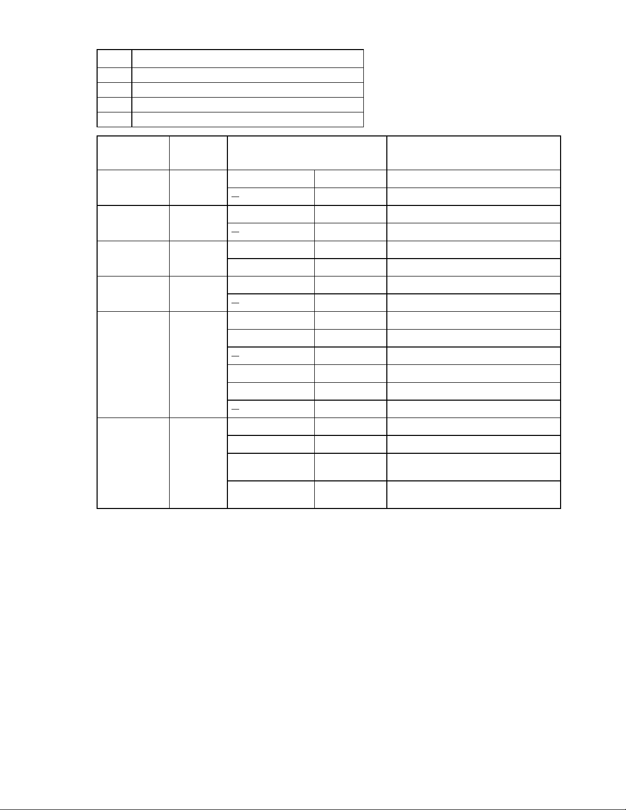
Page 52

BIOS setup menus
BIOS Menu
Description
Main
General product information including BIOS/memory information, system language, and
time/date
Advanced
Configuration information for legacy option ROM support, PCI subsystem, WHEA, trust
computing, CPU, SATA, USB, serial port redirection, and network stack
IntelRCSetup
Server chipset configuration for the north/south bridge and ME subsystem
Server Mgmt
BMC self-test status, timer settings, event log settings, and BMC network settings
GPNV Logs
View the system and SMBIOS event logs system
Security
Set or change the user and supervisor passwords
Boot
Configure the boot device priority
Save & Exit
Save changes and exit, discard changes and exit, discard changes, or load defaults
SMBIOS Event Log
Description
0x07
POST memory resize
0x08
POST errors
0x10
System limit exceeded
0x16
Log area reset
0x17
System boot
0xFF
End of log
0x80
IDE device failed
0x81
Flash device update operation failed
0x82
No more PCI resources available
0x83
No space for any more legacy OPROM
0x84
Invalid password entered three times
0x85
Clear CMOS
The following table provides descriptions for the top-level BIOS setup menus.
POST error message
There are three methods to treat the event/errors detected during POST:
Log to SMBIOS
Log to SEL
Shown on-screen during POST
SMBIOS event log
Configuration 52
Page 53

System event log (POST)
Sensor
Name
Sensor
Type
Sensor
Number
E/R
Type
Event
Data1
Event
Data2
Event
Data3
Description
BIOS POST
Sensor
0x0F
0x09
0x6F
0xC0
0x01
0xFF
System firmware error. No system
memory is physically installed in
the system.
0x0F
0x6F
0xC0
0x02
0xFF
System firmware error. No usable
system memory, all installed
memory has experienced an
unrecoverable failure.
0x0F
0x6F
0xC0
0x0A
0xFF
System firmware error. No video
device detected.
0x07
0x6F
0x02
0xFF
0xFF
FRBI/BIST failure.
0x10
0x6F
0x04
0xFF
0xFF
SEL full.
Entering the pop-up boot menu
To enter the pop-up boot menu, press F7 during system boot when the Press <F7> to enter Popup Boot
Menu message displays.
The pop-up boot menu screen displays as shown in the following figure.
Entering PXE boot
To access PXE boot:
1. Set Network as the first boot device in BIOS setup menu.
2. Select Network device from the pop-up boot menu.
Entering the BIOS setup menu
The BIOS setup menu is accessible using the following methods:
Connect a USB keyboard, mouse, and VGA monitor directly to the server.
Use a console (or terminal emulator connected to a computer) through the serial port on the rear of
the server.
To access the BIOS setup utility menus:
Configuration 53
Page 54

1. Press the power button on the front control panel to power up the server.
Beep Numbers
Description
1
Memory was not installed
1
Memory was installed twice (Install PEI memory routine in PEI core was called twice)
2
BIOS recovery started
3
DXE IPL was not found. Cannot locate DXE IPL PPI
DXE core firmware volume was not found. Cannot load DXE core file into memory
4
BIOS recovery failed
5
No memory detected
7
PEI reset is not available
Beep Numbers
Description
1
Invalid password
4
Some of the architectural protocols are not available
6
Flash update failed
7
DXE reset is not available
8
Platform PCI resource requirements cannot be met
2. Press F2 or DEL during system boot when the Press <DEL> or <F2> to enter setup displays.
3. Use the left and right arrow keys to navigate the different menu options. When a menu option is
selected, the top-level screen for that option appears.
4. Use the up and down arrow keys to scroll up and down to select an item on a top-level screen. When
the up and down arrow keys are pressed, the only options that are highlighted are the options that
can be modified.
o If an item can be modified, user instructions for modifying the option appear in the right column of
the screen.
o If an item is a link to a sub-screen, a prompt to press Enter to access the sub-screen appears in
the right column.
5. Modify the setup item and press F4 to save the changes and exit the screen.
6. Follow the instructions on the Save & Exit menu screen to save or discard your changes and exit the
BIOS setup utility.
BIOS beep codes
This section provides the BIOS beep codes including the PEI to report errors during memory initialization
and DXE to report errors during hardware initialization.
PEI beep codes
DXE beep codes
BIOS maintenance
This section provides information about upgrading the BIOS, clearing the BIOS password, clearing
CMOS, BIOS recovery, and a BIOS jumper description.
Configuration 54
Page 55

Upgrading the BIOS using DOS
The flash memory update utility loads a fresh copy of the BIOS into flash ROM. This utility only updates the
BIOS region.
BIOS update utility: AFUDOS.EXE
Boot the system to DOS environment and execute the following command to update BIOS:
AFUDOS <BIOS ROM File Name>[Option 1][Option 2]
or
AFUDOS<Output BIOS ROM File Name><Commands>
Commands
Use the mandatory field to select an operation mode.
o /O Save current ROM image to file
o /U Get and display ROM ID from BIOS ROM file
o /S Refer to Option: /S
o /D Verification test of given ROM File without flashing BIOS.
Options
Use the optional field to supply more information for flashing the BIOS ROM. The following lists the
supported optional parameters and format:
o /P Program main bios image
o /B Program Boot Block
o /N Program NVRAM
o /E Program Embedded Controller block if present
o /K Program all non-critical blocks
o /Kn Program n'th non-critical block only (0>= n <=7)
o /Q Quiet mode enable
o /REBOOT Reboot after update BIOS done
o /X Do not check ROM ID
o /S Display current system's BIOS ROM ID
o /R Preserve all SMBIOS structures during NVRAM programming.
o /Rn Preserve SMBIOS type N during Boot Block programming.
o /ECUF Update EC BIOS when newer version is detected.
o /Shutdown Shutdown after programming.
Rules
o Any parameter enclosed by <> is a mandatory field.
o Any parameter enclosed by [ ] is an optional field.
o <Commands> cannot co-exist with any [Options].
o The main BIOS image is the default flashing area if no options are present.
o [/REBOOT], [/X], and [/S] automatically enables the [/P] function automatically.
o If [/B] is present alone, only the boot block area needs to be updated.
o If [/N] is present alone, only the NVRAM area needs to be updated.
Configuration 55
Page 56

o If [/E] is present alone, only the embedded controller block needs to be updated.
Flash Command
Description
afudos XXXX.ROM /P
Program main BIOS image
afudos XXXX.ROM /P /B
Program main BIOS and BB (Boot Block)
afudos XXXX.ROM /P /B /N
Program main BIOS, BB and NVRAM
afudos XXXX.ROM /P /B /R
Program BB and main BIOS without SMBIOS
Clearing the BIOS password
If the user and/or administrator password is lost or forgotten, clear both passwords by moving the
password clear jumper into the clear position.
The BIOS determines if the password clear jumper is in the clear position during BIOS POST and clears
any passwords if necessary. The password clear jumper must be restored to its original position for the
new password to remain set.
Clearing the CMOS
The CMOS clear jumper uses RTCRST# to:
Clear CMOS values
Set the RTC power well configuration bits to default.
To compatible legacy BIOS for user who is used to use legacy BIOS, BIOS provide the function to restore
the default settings of BIOS Setup when CMOS is cleared, even though UEFI BIOS store BIOS settings to
NVRAM.
There are two methods to clear the CMOS:
Clear the CMOS jumper.
Remove the CMOS battery when the system is in AC OFF status.
Important: After clearing the CMOS, the BIOS setup default is restored, but the password that was set by
the user is still reserved.
Recovering the BIOS
If the BIOS image is corrupt, a system BIOS update fails, or the system fails to complete POST, the BIOS
must enter recovery mode. In recovery mode, an entire BIOS image can be refreshed to BIOS flash part.
To recover the BIOS:
1. Turn off the system power.
2. Open the chassis.
3. Move the BIOS recovery jumper from the normal positions 1-2 to the recovery positions 2-3.
4. Close the chassis.
5. Copy the latest BIOS image file (DC1F1XXX.ROM) to a USB drive, XXX is the revision number. A
bootable USB is not required.
6. Insert the USB drive into the system.
7. Power up the system.
8. The system display setup <Recovery> screen displays automatically and flash update automatically
runs.
Configuration 56
Page 57

9. Select Proceed with flash update. Flash update automatically runs.
Jumper
Description
Jumper Adjustment
J12
PASSWORD CLEAR
1-2 (Default): Normal operation
2-3: Password clear
J11
CMOS CLEAR
1-2 (Default): Normal RTC reset
2-3: Clear RTC registers
J19
MEFIRMWARE
RECOVER
1-2 (Default): Normal operation
2-3: Force ME to enter recovery default
J17
BIOS RECOVERY
MODE
1-2 (Default): Normal operation
2-3: Force BIOS to enter recovery mode
J21
ME
MANUFACTURING
MODE
1-2: ME Flash Override (used for ME entire update)
2-3 (Default):Normal
10. Wait until <Program new data> completes, and then press Enter to shut down the system.
If the signature of FV_MAIN area is invalid, the BIOS automatically enters recovery mode; if this occurs,
only perform steps 5 through 10.
After recovery completes, if the recovery jumper forces the BIOS recovery turn off the system, and then
restore the jumper to its normal position.
BIOS jumpers
This section provides information about the BIOS. See the following table to locate the BIOS maintenance
jumpers.
Configuration 57
Page 58

Item
Description
1
Clear password J12
2
Clear CMOS J11
3
BIOS recovery J17
4
ME firmware recover J19
5
ME manufacturing mode J21
Checking the FW version
Checking the BIOS version using Linux
1. Log into Linux.
2. Open the terminal. Execute the dmidecode t 0 command to display the BIOS version, as shown in
the following figure.
Checking the BIOS version using the BIOS setup utility
1. Log into the BIOS setup utility.
2. Use the arrow keys to select the Main, menu to display the BIOS version as shown in the following
figure.
Configuration 58
Page 59

Checking the BMC version using Linux
1. Log into Linux.
2. Open the terminal. Execute the ipmitool –I open mc info command to display the BMC version
as shown in the following figure.
Checking the BMC version using the web GUI
1. Log into the web GUI.
2. Click Properties to display the BMC version, as shown in the following figure.
Configuration 59
Page 60

Checking the event log
Checking the system event log using Linux remote desktop
1. To check the system event log using Linux Log into Linux.
2. Open the terminal.
3. Execute the ipmitool -I lanplus –H BMCIP –A admin –P password sel list command
to check the system event log.
The system event log is shown in the following figure.
Checking the system event log using the web GUI
To check the system event log using the web user interface:
1. Log into the web GUI.
2. Click System Event Log to display the system event log, as shown in the following figure.
Configuration 60
Page 61

Checking the event log using the BIOS setup utility
To check the event log using the BIOS setup utility:
1. Enter the BIOS setup utility, and then select the Event Logs menu.
Configuration 61
Page 62

2. Use the arrow keys to select to the View SMBIOS Event Log option, and then press Enter key.
The SMBIOS Event Log displays. The possible error messages that the event log might display are
shown in the following table.
3. Take one log for example, move cursor to the second log, then detailed event information will be
shown on top right corner as below.
4. Use the arrow keys to select the View System Event Log option, and then press the Enter. The list
of system events appears in the System Event Log, as showing in the following figure. The BMC web
user interface can also report system event logs.
Configuration 62
Page 63

5. Use the arrow keys to select one of the event logs. The detailed information for the event log displays
under Event Description: in the right pane.
Configuration 63
Page 64

Configuration 64
Page 65

Diagrams
System board diagram
Diagrams 65
Page 66

Spare parts catalog
Customer self repair
HP products are designed with many Customer Self Repair (CSR) parts to minimize repair time and allow
for greater flexibility in performing defective parts replacement. If during the diagnosis period HP (or HP
service providers or service partners) identifies that the repair can be accomplished by the use of a CSR
part, HP will ship that part directly to you for replacement. There are two categories of CSR parts:
Mandatory Parts for which customer self-repair is mandatory. If you request HP to replace these
parts, you will be charged for the travel and labor costs of this service.
Optional Parts for which customer self-repair is optional. These parts are also designed for
customer self-repair. If, however, you require that HP replace them for you, there may or may not be
additional charges, depending on the type of warranty service designated for your product.
Important: Some HP parts are not designed for customer self-repair. In order to satisfy the customer
warranty, HP requires that an authorized service provider replace the part. These parts are identified as
“No” in the Illustrated Parts Catalog.
Based on availability and where geography permits, CSR parts will be shipped for next business day
delivery. Same day or four-hour delivery may be offered at an additional charge where geography
permits. If assistance is required, you can call the HP Technical Support Center and a technician will help
you over the telephone. HP will specify if a defective part must be returned to HP. In cases where it is
required to return the defective part to HP, you must ship the defective part back to HP within a defined
period of time, normally five (5) business days. The defective part must be returned with the associated
documentation in the provided shipping material. Failure to return the defective part may result in HP
billing you for the replacement. With a customer self-repair, HP will pay all shipping and part return costs
and determine the courier/carrier to be used.
For more information about HP's Customer Self Repair program, contact your local service provider. For
the North American program, refer to the HP website.
Parts only warranty service
Your HP Limited Warranty may include a parts only warranty service. Under the terms of parts only
warranty service, HP will provide replacement parts free of charge.
For parts only warranty service, CSR part replacement is mandatory. If you request HP to replace these
parts, you will be charged for the travel and labor costs of this service.
Spare parts catalog 66
Page 67

Item
Description
Spare Part Number
Customer Self Repair
1
Front USB board
35102SS00-245-G
Mandatory
2
Front panel control board
10010SS00-600-G
Mandatory
3
HDD backplane
1A219PC00-600-G
Mandatory
4
1U-1slot PCIe riser
1A32QG600-600-G
Mandatory
5
OCP mezz card, 10G 82599, Intel, dual port
1A32LVP00-600-G
Mandatory
6
MB-Hercules-SKU_A (OCP+2x16+1x8)
1A32UTH00-600-G
Mandatory
MB-Hercules-SKU_B (4GbE+2x16+1x8)
1A32UTJ00-600-G
Mandatory
MB-Hercules-SKU_C (2GbE+2x16+2x8)
1A32UTL00-600-G
Mandatory
MB-Hercules-SKU_D
(OCP+2 x 1G LAN+2x16+1x8)
1A32UYV00-600-G
Mandatory
7
2-AIRDUCT_HERCULES.PRT
1B511A600-600-G
Mandatory
8
Power to HDD BP switch cable
35072F700-245-G
Mandatory
9
CPU power Y cable
35072F900-245-G
Mandatory
10
Front USB cable
35102SS00-245-G
Mandatory
11
Front control board cable
35102ST00-245-G
Mandatory
12
CPU1 heatsink,
106mm(L) x 70mm(W) x 26.5mm(H)
460404T00-548-G
Mandatory
13
CPU2 heatsink,
106mm(L) x 80mm(W) x 25.5mm(H)
48011FA00-548-G
Mandatory
14
System 4056 FAN
490204P00-065-G
Mandatory
15
650W platinum PSU(PMBus Rev 1.2)
(with HVDC and common cable design)
860204A00-515-G
Mandatory
16
LSI 9271-8i Card
10040JH00-432-G
Mandatory
17
LSI 9271-8i with Cache Vault LSICVM01 Card
1A32YEK00-600-G
Mandatory
18
LSI-2308 SAS HBA MEZZ Card
1A32ULQ00-600-G
Mandatory
19
HP CL2100 807S LSI Crd SAS Cable Kit
1A21AWB00-600-G
20
Onboard PCH Mini SAS to BP cable Assembly
1A32YGL00-600-G
21
Tool-less Friction Rail Kit
1A32W7700-600-G
Mandatory
22
Intel E5-2680v3
11010S800-187-G
Mandatory
Intel E5-2660v3
11010S900-187-G
Mandatory
Intel E5-2630v3
11010SA00-187-G
Mandatory
Intel E5-2620v3
11010S100-187-G
Mandatory
Intel E5-2603v3
11010S200-187-G
Mandatory
23
DIMM,8GB PC4-2133P-R,1Gx4
800305S00-216-G
Mandatory
DIMM,8GB PC4-2133P-R,1Gx4
800305T00-026-G
Mandatory
DIMM,16GB PC4-2133P-R,1Gx4
800305D00-216-G
Mandatory
DIMM,16GB PC4-2133P-R,1Gx4
800305U00-220-G
Mandatory
Replaceable components
Spare parts catalog 67
Page 68

Item
Description
Spare Part Number
Customer Self Repair
24
1TB SATA 7.2k HDD SFF
81050AL00-509-G
Mandatory
300GB 6G SAS 10K 2.5in DP ENT SC TV HDD
810900J00-131-G
Mandatory
600GB 6G SAS 10K 2.5in HDD
810200B00-509-G
Mandatory
600GB 6G SAS 10K 2.5in HDD
810900D00-131-G
Mandatory
240GB 6G SATA 2.5in VE SCC SSD
810804500-187-G
Mandatory
800GB 6G SATA 2.5in SSD
810804H00-187-G
Mandatory
1
Mandatory Parts for which customer self repair is mandatory. If you request HP to replace these parts, you will be
charged for the travel and labor costs of this service.
2
Optional Parts for which customer self repair is optional. These parts are also designed for customer self repair. If,
however, you require that HP replace them for you, there may or may not be additional charges, depending on the
type of warranty service designated for your product.
3
No Some HP parts are not designed for customer self repair. In order to satisfy the customer warranty, HP requires
that an authorized service provider replace the part. These parts are identified as “No” in CSR.
Spare parts catalog 68
Page 69

Troubleshooting
WARNING: To avoid potential problems, ALWAYS read the warnings and cautionary
information in the server documentation before removing, replacing, reseating or modifying
system components.
Troubleshooting preparation
Pre-diagnostic
Important: Refer to the server documentation for information on procedures, hardware options, software
tools and operating systems supported by the server.
Follow the following pre-diagnostic steps before system troubleshooting process:
1. Review the important safety information.
2. Collect symptom information.
3. Prepare the server for troubleshooting.
4. Use the troubleshooting flowchart to begin the troubleshooting process.
Symptom collection
Before troubleshooting a server problem, collect the following information:
Does the server power on?
Does the server complete POST?
If not, then what do the health LEDs indicate? Is video display available? If the server completes POST
and video is available, are there any POST error messages?
Record the text of the POST error message as displayed.
Does the server successfully boot an operating system or hypervisor? If not, does the server display
any of the following symptoms?
o An uncorrectable machine check exception
o Stop error or blue screen (Windows)
o Purple diagnostic screen (Linux)
o Linux kernel panic
o A system “hang”
o A system “freeze”
If the problem occurs after an OS is installed:
o Does the problem occur when a new application is loading or a patch is applying?
o What symptoms did the server display when the server malfunctioned? (for example, did it reboot,
were there LED codes, health logs, messages on the screen, and so forth)
Troubleshooting 69
Page 70

Are any indications present that show that the malfunction was reported as a memory error, PCI error,
or so forth? The processor now contains the memory controller and PCI Express controller, so faults in
other areas may be attributed to a processor malfunction.
When did the problem occur?
Record exactly when the problem happens (include the date and time). If it happens more than once, keep
a list of all symptoms for each occurrence.
What events preceded the failure?
After which steps does the problem occur?
What has been changed since the time the server was working?
Did you recently add or remove hardware or software?
How long has the server exhibited problem symptoms?
If the problem occurs randomly, what is the duration or frequency?
Observe the server LEDs and their statuses. See the LED Indicators for more information.
Prepare the server for diagnosis
1. Be sure that the server is in the proper operating environment with adequate power, air conditioning,
and humidity control. For required environmental conditions, see the server documentation.
2. Record any error messages displayed by the system.
3. Remove all external peripherals such as the network cables, monitor, keyboard, and mouse.
4. Collect all tools and utilities necessary to troubleshoot the problem, such as a Torx screwdriver,
loopback adapters, ESD wrist strap, and software utilities.
5. Determine if the server will troubleshoot offline or online.
6. To diagnose the server offline, power down the server and peripheral devices. If possible, always
perform an orderly shutdown:
a. Exit any applications.
b. Exit the operating system.
c. Power down the server.
7. Disconnect any peripheral devices not required for testing (any devices not necessary to power up the
server).
Performing processor procedures in the troubleshooting process
Before performing any troubleshooting steps that involve processors, review the following guidelines:
Be sure that only authorized personnel perform the troubleshooting steps that involve installation,
removal, or replacement of a processor.
Always locate the documentation for your installed processor model before performing any steps that
require installing, removing, or replacing a processor. If you cannot locate the hard copy of the
instructions, locate the server user and maintenance guide in the HP Enterprise Information Library
(http://www.hp.com/go/enterprise/docs).
Never touch the contacts in the processor socket. THE PINS ON THE SYSTEM BOARD ARE VERY
FRAGILE AND EASILY DAMAGED. If the contacts inside the processor socket are damaged, you must
replace the system board.
Troubleshooting 70
Page 71

Some processor models require the use of a processor installation tool, and specific steps are
CAUTION: Before removing or replacing any processors, be sure to follow the guidelines
provided in removing and installing processors steps.
Failure to follow the recommended guidelines can cause damage to the system board, requiring
replacement of the system board.
documented to ensure that they do not damage the processor or processor socket on the system
board. For server models that have pins inside the processor socket, remember that THE PINS ON THE
SYSTEM BOARD ARE VERY FRAGILE AND EASILY DAMAGED. If the socket is damaged, you must
replace the system board.
Always complete all other troubleshooting procedures before removing or replacing a processor.
Breaking the server down to the minimum hardware configuration
During the troubleshooting process, it might be necessary to break down the server to the minimum
hardware configuration. A minimum configuration consists of only the components needed to boot the
server and successfully pass POST.
When requested to break the server down to the minimum configuration, uninstall the following
components, if installed:
All additional DIMMs
Leave only the minimum required to boot the server either one DIMM or a pair of DIMMs.
All additional cooling fans, if applicable
All additional power supplies, if applicable (leave one installed)
All hard drives
All optional mezzanine cards
All expansion boards
Before removing the components, be sure to determine the minimum configuration for each component and
follow all guidelines in the server user and maintenance guide.
Always use the recommended minimum configuration above before removing any processors. If you are
unable to isolate the issue with the configuration above, you will then remove all but one of the processors.
Troubleshooting 71
Page 72

Diagnostic flowcharts
Troubleshooting flowcharts
To effectively troubleshoot a problem, HP recommends that you start with the first flowchart in this section,
“Start diagnosis flowchart (on page 72)” and follow the appropriate diagnostic path. If the other flowcharts
do not provide a troubleshooting solution, follow the diagnostic steps in “General diagnosis flowchart (on
page 74)”.
The General diagnosis flowchart is a generic troubleshooting process to be used when the problem is not
server-specific or is not easily categorized into the other flowcharts.
The available flowcharts include:
Start diagnosis flowchart
Remote diagnosis flowchart
General diagnosis flowchart
Power-on problems
POST problems flowchart
Operating system boot problems flowchart
Some information provided in the flowcharts can be further explained in other sections of this document.
Start diagnosis flowchart
Use the following flowchart to start the diagnostic process.
Diagnostic flowcharts 72
Page 73

Start Diagnosis
Do you want
to perform the Remote
Diagnosis?
Does the server
power on?
Do you want
to perform the General
Diagnosis?
Does the server
complete POST?
Does the server
boot to the OS?
Go to
Remote
Diagnosis
Go to
general
Diagnosis
Go to
Power on
problems
Go to POST
problems
Go to OS
Boot
Problems
Yes
Yes
NO
NO
NO
Yes
Yes
End
Yes
NO
NO
Remote diagnosis flowchart
The Remote diagnosis flowchart provides a generic approach to troubleshoot a server from a remote
location.
Diagnostic flowcharts 73
Page 74

Start Remote
Troubleshooting
BMC,
remote Desktop
services
Use BMC
to Troubleshoot
the server
Does the
condition still exist?
Use the Onboard
Administrator to
Troubleshoot the
server
Does the
condition still exist?
End
Download
OS system log and
BMC log
Contact
Support
RDS
BMC
No
Yes
NoYes
General diagnosis flowchart
The General diagnosis flowchart provides a generic approach to troubleshooting. If you are unsure of the
problem, or if the other flowcharts do not fix the problem, use the following flowchart.
Diagnostic flowcharts 74
Page 75

Start General
Diagnosis
Record
Symptom
information
Reboot
Server to see
If condition
still exists.
Is this a
Newly Installed
Server?
Reseat any components that may have
Come loose during shipping and reboot
the server
Does the
Condition still
Exist?
Were options
Added or was the
Configuration
Changed
recently?
Check for Service
Notifications
Download the
Latest software
And firmware.
Does the
Condition still exist?
Isolate what was changed. Verify it Was
Installed correctly. Restore server to the
Last known working state or original
shipped configuration.
Does the
Condition still
Exist?
Isolate and minimize the Memory
configuration
Troubleshoot or
replace basic
server spare parts
Does the
Condition still exist?
Break server down
To minimal
configuration
Does
the condition
still exist?
Does
the condition still
exist?
Add one part at a
Time back to
Configuration to isolate
faulty component.
Does
the Condition
still exist?
Record action
taken
Record symptom and error
Information on the repair tag
Sending back a failed part.
Ensure the
following Information is
available: OS log And
BMC log
Contact
Support
End
Yes
No
Yes
No
No
No
Yes
No
Yes
No
Yes No
No
Yes
Yes
No
Power-on problems flowchart
Symptoms:
The server does not power on.
The system power LED is off or flashing.
The health LED is solid orange.
Diagnostic flowcharts 75
Page 76

Possible causes:
Start Power-on
Problems
Check for
loose power cables
Disconnect the
Power cable, remove
And then reinstall the
power supply
What color is
The system
power LED?
Is the system
power LED flashing green or
solid green?
Press the power
On/Standby button
And wait 45seconds
Is the power
Source operating
properly?
Replace the power
source
Does condition
still exIst?
End
Replace the power
supply
Contact
Support
If condition persists
Replace
component
If condition persists
Replace component
Are any
Component SID
LED illuminated?
What color is
The system
health LED?
Off
Green
Flash green
Solid
Yes
No
yes
No
No
Yes
Green
orange
Improperly seated faulty power supply
Loose or faulty power cord
Power source problem
Improperly seated component or interlock problem
POST problems flowchart
Symptoms:
Server does not complete POST
Server completes POST with errors
Diagnostic flowcharts 76
Page 77

Record action
taken
End
Does The
Condition still
exist?
Add one part at a
Time back to
Configuration to
isolate component
Break server down
To the minimum
configuration
Troubleshoot or
Replace basic
server spare parts
If sending back a failed part,
Record symptom& error
information on repair tag
Start server POST
problems
Video output
available?
Are POST error
Message
Displayed.
Verify video is
cabled correctly.
Are the fans
operating?
Is the health
LED orange?
Are there any
beep codes?
Reseat the Indicated
Component. Check for
loose connections
If condition still exists, replace
indicated component.
Does the
error code Provide
direction?
Check the error
symptom in
Troubleshooting
specification
Isolate and
Minimize the
Memory
configuration
Does The
Condition still
exist?
Does The
Condition still
exist?
Does The
Condition still
exist?
Record action
taken
Contact
Technical Support
Ensure the
following Information is
available: OS log And
BMC log
Yes
yes
yes
yes
yes
yes
Yes
Yes
Yes
Yes
No
No
No
No
No
No
No
No
Check the
troubleshooting
specification
Operating system boot problems flowchart
Possible Causes:
Corrupted OS
Hard drive subsystem problem
Incorrect boot order setting in the BIOS
Hardware problem
Diagnostic flowcharts 77
Page 78

Troubleshoot or
replace basic
server spare parts
Does the
Condition still exist?
Break server down
To minimal
configuration
Does
the condition
still exist?
Does
the condition still
exist?
Add one part at a
Time back to
Configuration to isolate
faulty component.
Does
the Condition
still exist?
Record action
taken
Record symptom and error
Information on the repair tag
Sending back a failed part.
Ensure the
following Information is
available: OS log And
BMC log
Contact
Support
End
Yes
No
Yes No
No
Yes
Yes
No
Isolate and minimize the
Memory configuration
Does the
Condition still exist?
Does the
Condition still exist?
Corrupted OS
Driver compatibility issues
The virus
Reinstall the
operation system
Reboot and
Enter The safe Mode
Successfully?
Does the crash,
blue screen , Auto reboot
And some error info
symptom exist?
Start OS boot
problems
Does the boot
Device cannot
be detected?
Check for loose
Data cable and
Power supply
Cable and so on
Does the
Condition still exist?
Reset the boot
Device correctly in
BIOS
Repair the OS configuration files
Update correct drives
Scan for viruses with an updated
virus scan utility
record relevant log
No No
No
No
No
Yes
Yes
Yes
Yes
Yes
No
See the SAS RAID card and
hard Drive documentations
And to be sure is matched
the server
Troubleshooting general problems
Resolving common problems
Common problem guideline
1. System cannot power on
o Be sure that all power and I/O cords are securely connected
o Verify that the the system board is powered up
Diagnostic flowcharts 78
Page 79

o Configure the server with the minimum components (one CPU, the least amount of memory, and
CAUTION: Failure to properly handle the CPU can cause damage to CPU components and the
system board connector. It can also cause the system to collapse.
connect only the display monitor and keyboard). Connect directly to the system board jumper to
determine if the server now starts normally
o Check the power. Remove all of the the power cables. Connect the green cable and the black
cable on the PSU power to check the result
o If problems continue to occur, remove and reinstall each device, checking the connectors and
sockets for bent pins or other damage
2. System frequently reboots
There are generally three factors that might cause the system to reboot:
o Breakdown of power
Supply power to the server from an available power source
o Problems with memory
Check the event log or memory configuration from the BIOS to determine if there is a problem
with the memory which requires replacing the memory. Check the display to determine if the
memory error was detected during POST. If the event log shows that a memory error caused the
memory problem, re-seat all of the memory by removing and re-installing all of the memory
modules. If reseating the memory modules does not resolve the memory/reboot problem, replace
the memory.
o Problems with the software
Update the software or re-install the system
3. System stopped issue
Track the reasons the system stopped from the software and hardware, respectively.
o Software tracking: Check the system event log to identify and locate the problem.
o Hardware tracking: The power supply is not sufficient; HDD/SSD has some problem (scan the
surface of them to check). Addon cards might also cause the system to halt (for example,
SCSI/RAID cards or other PCI facilities).
Pay attention to any possible reasons any of the hardware components might have caused the system
to stop, even if the problem has been resolved. Observe the server to confirm that the system stop
issue has whether it has been thoroughly resolved.
4. Failure to recognize the HDD during system installion
o Determine if the HDDs were installed in the HDD carriers
o Determine if the SAS/SATA cables are correctly connected
o Check the HDD LED indicators to determine if the drives are receiving power
o Determine if the storage controller driver is properly installed or the driver is not compatible with
the HDD.
o Determine if the driver is compatible with the HDD
Handling and installing the CPU
When handling a CPU, observe the following guidelines:
Before installing the CPU, determine if the CPU has bent pins
Diagnostic flowcharts 79
Page 80

Be careful not to touch the CPU pins
CAUTION: Failure to properly handle DIMMs can cause damage to DIMM components and
the system board connector.
DIMM population order and configuration is critical in maximizing performance for the system.
When installing the CPU, remember to place the side with triangle point onto the triangle on the
board
Correctly installing the CPU is not enough. You must also consider the heat radiation; if the CPU
temperature is too high, it might affect the system performance. The heat sink is used for the CPU heat
radiation. When you install heat sink, observe the following guidelines:
When you install the heat sink:
Align the heat sink so the sticker label faces the memory module
Secure the heat sink with the screw
DIMM handling and installation guidelines
When handling a DIMM, observe the following guidelines:
Avoid electrostatic discharge.
Always hold DIMMs by the side edges only.
Avoid touching the connectors on the bottom of the DIMM.
Never wrap your fingers around a DIMM.
Avoid touching the components on the sides of the DIMM.
Never bend or flex the DIMM.
When installing a DIMM, observe the following guidelines:
Before seating the DIMM, open the DIMM slot and align the DIMM with the slot. Some servers require
the use of a DIMM tool to open the slots.
To align and seat the DIMM, use two fingers to hold the DIMM along the side edges.
To seat the DIMM, use two fingers to apply gentle pressure along the top of the DIMM.
SAS/SATA and SSD drive guidelines
When adding drives to the server, observe the following general guidelines:
Drives must be the same capacity to provide the greatest storage space efficiency when drives are
grouped together into the same drive array.
Drives in the same logical volume must be of the same type.
Diagnostic flowcharts 80
Page 81

Hardware problem troubleshooting
Power problems
Power source problems
1. Press the Power On/Standby button to be sure it is on. If the server has a Power On/Standby button
that returns to its original position after being pressed, be sure you press the switch firmly.
2. Plug another device into the grounded power outlet to be sure the outlet works. Also, be sure the
power source meets applicable standards.
3. Replace the power cord with a known functional power cord to be sure it is not faulty.
4. Replace the power strip with a known functional power strip to be sure it is not faulty.
5. Have a qualified electrician check the line voltage to be sure it meets the required specifications.
6. If Enclosure Dynamic Power Capping or Enclosure Power Limit is enabled on supported servers, be
sure there is sufficient power allocation to support the server.
7. Be sure no loose connections exist.
Power supply problems
1. Be sure no loose connections exist.
2. If the power supplies have LEDs, be sure they indicate that each power supply is working properly. If
the LEDs indicate a problem with a power supply (6.7Hz flashes green or off), then check the power
source. If the power source is working properly, then replace the power supply.
If the 6.7Hz green LED is flashing or off,it could mean any of the following:
o AC power unavailable
o Power supply failed
General hardware problems
Problems with new hardware
1. Be sure the hardware being installed is compatible with the server.
2. Be sure the new hardware is installed properly. To be sure that all requirements are met, see the
device, server, and OS documentation.
Common problems include:
o Connection of the data cable, but not the power cable, of a new device
o Loose connections exist
3. Be sure no memory, I/O or interrupt conflicts exist.
4. Be sure all cables are connected to the correct locations.
5. Be sure other components were not accidentally unseated during the installation of the new hardware
component.
6. Be sure all necessary software updates, such as device drivers, ROM updates, and patches, are
installed and current, and is the latest version.
7. Be sure all boards are properly installed in the server.
Diagnostic flowcharts 81
Page 82

8. Boot to the BIOS to determine if the utility is configured.
9. Replace another different known functional device to plug into the location to be sure that the server is
not faulty.
10. Replace another same model device.
Unknown problem
1. Check the server LEDs to see if any statuses indicate the source of the problem.
2. Power down and disconnect power to the server. Remove all power sources to the server.
3. Be sure no loose connections exist.
4. Add the debug card before reconnecting power.
5. Reconnect power, and then power on the system.
6. See the number shown on the debug card. If there is an error on the debug card indicating that the
server will stop, see the BIOS specifications (standard status codes) to determine where the process
stopped. For example, if the number on the debug card points to memory, re-seat the memory. If
reseating the memory does not resolve problem, consider using a different memory module to verify it
is a memory problem.
Third-party device problems
1. See the device documentation to be sure the device is properly installed.
2. If the device is the only device on a bus, be sure the bus works by installing a different device on the
bus.
3. Be sure the latest device drivers are installed.
4. Uninstall the device. If the server functions without the removed device, the problem might exist with
the device rather than the server. Either the server does not support the device, or a conflict exists with
another device.
5. Remove other device. If the server functions properly, a conflict exists with another device. If the
device still does not function properly, see the server and operating system documentation to be sure
that the server and operating system support the device.
Internal system problems
CD-ROM and DVD drive problems
1. System does not boot from the drive
o Be sure no loose connections exist.
o Be sure the media from which you are attempting to boot is not damaged and is a bootable CD.
o Be sure legacy support for a USB CD-ROM driver is enabled in the BIOS and be sure that the
drive boot option in the BIOS is set up so that the server boots from the CD-ROM drive first.
o If the data read from the driver is inconsistent, or if the drive cannot read the data, be sure that the
inserted CD or DVD format is valid for the drive. For example, be sure not to insert a DVD into a
drive that only supports CDs.
2. Drive is not detected
o Be sure no loose connections exist.
o See the drive documentation to be sure cables are connected as required.
Diagnostic flowcharts 82
Page 83

o Be sure the cables are working properly. Replace with known functional cables to test whether the
original cables were faulty.
o Be sure the USB port functions normally with a USB CD-ROM drive.
o Be sure legacy support for a USB is set enabled in the BIOS.
Drive problems (hard drives and solid state drives)
1. Drives are not recognized
o See the hard drive and server documentation to be sure the hard drive is compatible with the
server.
o See the SAS RAID card documentation to be sure the RAID card is compatible with the server.
o Be sure no power problems exist.
o Be sure no loose connections exist.
o Be sure the driver or backplane is connected properly.
o Be sure legacy support for SAS is set up correctly.
o Connect only one hard drive directly from the SATA port to determine if the server is causing the
problem.
o Boot to the BIOS RU tool to determine if the SAS controller can be detected.
o Connect only one hard drive directly from the SAS port using a SAS-SATA cable to determine if
the problem is with the SAS cable.
o Replace the current SAS cable with another correctly functioning SAS cable to determine if the
problem is with the SAS cable.
o Be sure the RAID card controller is correct and supports the hard drive.
o Replace the current SAS RAID card with a correctly functioning SAS RAID card.
o Be sure the SAS backplane board driver is the latest driver
o Replace the current backplane board with a correctly functioning backplane board
2. Data is inaccessible
Action:
o Be sure the files are not corrupt. Run the repair utility for the operating system.
o Be sure no viruses exist on the server. Run a current version of a virus scan utility.
o Be sure the TPM is enabled in BIOS.
o Be sure the firewall setting is correct.
o When migrating encrypted data to a new server, be sure to follow the recovery procedures.
USB drive key problems
System does not boot from the drive:
Be sure that USB is enabled in the BIOS
Be sure the drive boot order in the BIOS is set so that the server boots from the USB drive key
Reseat the USB drive key
Diagnostic flowcharts 83
Page 84

Fan problems
Fan speed too fast:
Be sure the fans are properly seated and working:
a. Determine if the fan cables are corresponded to the slots.
b. Determine if the fan cables are correctly plugged into the slot pins.
Be sure no ventilation problems exist.
Be sure the BMC firmware is the latest.
Reseat the fan cables and restart the server.
Memory problems
1. Server fails to recognize existing memory:
o Be sure the server supports the memory modules.
o Be sure the memory modules are correctly installed in a supported configuration.
o Be sure the memory modules are properly seated.
o Reseat the memory.
o Use a known working memory module to test each slot to determine there is a problem with the
slot.
o Test each bank of DIMMs by removing all other DIMMs. Then, isolate the failed DIMM by
switching each DIMM in a bank with a known working DIMM.
2. Server fails to recognize new memory:
o Be sure the server supports the new memory modules.
o Be sure the new memory is the correct type for the server and is installed correctly.
o Be sure no conflicts are occurring with existing memory.
o Use a known working memory module to test each slot to determine if there is a problem with the
slot.
o Reseat the new memory.
3. Invalid memory configuration:
o DIMMs are installed when no corresponding processor is detected.
Description: A processor must be installed to use memory.
Action: Populate the processor socket or remove the DIMM.
o DIMM size parameters not supported:
Possible cause: The installed memory module is an unsupported size.
Action: Install a memory module of a supported size.
o Incomplete bank detected in bank X
Possible cause: The bank is missing one or more DIMMs.
Action: Fully populate the memory bank.
o Mismatched DIMMs within DIMM Bank
Possible cause: The installed DIMMs in the same bank are of different sizes.
Action: Install correctly matched DIMMs.
Diagnostic flowcharts 84
Page 85

o Unsupported DIMM in Socket X
Possible cause: Unregistered DIMMs or insufficient DIMM timings.
Action: Install registered ECC DIMMs.
4. Memory configuration warning
The DIMM in socket X does not have a primary width of 4 and only supports standard ECC.
Advanced ECC does not function when mixing DIMMs with primary widths of x4 and x8.
Possible cause: The installed DIMMs have a primary width of x8.
Action: Install DIMMs that have a primary width of x4 if advanced ECC memory support is required.
5. DIMM initialization error
Receive enable error. Cannot train memory.
Possible cause: The system receives a receive enable error during memory training.
Action: Contact JV support.
6. DIMM configuration error
o Quad Rank DIMMs must be installed in the first socket of any memory channel in which they are
populated. System stopped
Possible cause: Quad rank DIMMs are installed after SR or DR DIMMs.
Action: Be sure that quad rank DIMMs are installed in the first socket of any memory channel.
o UDIMMs and RDIMMs are installed in the system. The system cannot have both types of DIMMs
installed. System stopped
Possible cause: A DIMM configuration error exists with mismatched DIMMs.
Action: Be sure all DIMMs are of the same type.
7. Invalid Lockstep memory configuration
Possible cause: The memory is not installed properly to support Lockstep mode.
Action: Install or reinstall DIMMs to support mirrored mode.
8. Mirror memory configuration
o Memory sizes on boards X and Y do not match
Possible cause: The overall size of two boards that are participating in a mirrored configuration
does not match.
Action: Install or reinstall the DIMMs to support mirrored mode.
9. Non-numeric messages or beeps only
o Advanced memory protection mode: Advanced ECC
Possible cause: Advanced ECC support is enabled.
Action: None.
o Advanced memory protection mode: Advanced ECC with hot-add support
Possible cause: Advanced ECC with hot-add support is enabled.
Action: None
Processor problems
Be sure that the server supports each processor and that each processor is correctly installed.
Diagnostic flowcharts 85
Page 86

Only supported processors should be installed. Specific steps are required for the installation of
processors.
Be sure that the socket pins on each processor are intact
Replace the processor with another processor that is known to be properly functioning.
Network connection problems
1. Network not working
o Be sure that no loose connections exist between the LAN port and the system board.
o Be sure no loose connections exist between the LAN port and the LAN cable.
o Determine if the software is causing the problem
o Replace the LAN cable with a LAN cable that is known to be functioning properly
o Use the latest LAN card driver when installing the OS, and be sure the server and the OS support
the controller.
o Be sure a valid IP address is assigned to the controller and that the configuration settings are
correct.
o Restart the server to determine if the network starts working.
2. Network stops working
o Be sure no loose connections exist.
o Be sure the correct network driver is installed for the controller and that the driver file is not
corrupt. Reinstall the driver.
o Test the network cable to verify that it is functioning properly by replacing it with a cable that is
known to be properly functioning.
o Be sure the network controller is not damaged.
o Reinstall the network driver.
o Restart the server to determine if the network starts working
3. Network stops working when an adding an external board
Action:
o Be sure no loose connections exist.
o Be sure the server and OS support the external board.
o Be sure the new external board does not change the server configuration
o Be sure the correct driver is installed for the network controller.
o Reinstall the network driver.
o Restart the server to determine if the network starts working.
External device problems
Mouse and keyboard problems
Be sure no loose connections exist.
Be sure the keyboard or and mouse is connected to the correct ports.
Be sure the keyboard or mouse is clean.
Diagnostic flowcharts 86
Page 87

Be sure legacy support for USB is enabled in the BIOS.
Replace the device with a known working equivalent device (another similar mouse or keyboard).
Restart the system and determine if the input device functions correctly after the server restarts.
Cable problems
Unwarranted driver failures while using an older mini SAS cable. If using an older cable that is near the
life expectancy, replace the Mini SAS cable.
Software problem troubleshooting
The best sources of information for software problems are the operating system and application software
documentation, which might also point to fault detection tools that report errors and preserve the system
configuration. Other useful resources include the drivers matched with the operating system.
Use either utility to gather critical system hardware and software information and to help with the problem
diagnosis.
Operating system problems and resolutions
Operating system problems
1. Acting system locks up
o Scan for viruses with an updated virus scan utility.
o Review the system event log.
o Review the BIOS log.
o Gather the BMC SEL information for review, if needed.
2. Errors are displayed in the error log
Follow the information provided in the error log, and then see the operating system documentation.
3. Problems occur after the installation of a service pack
Follow the instructions for updating the operating system.
Operating system updates
Use care when applying operating system updates (Service Packs, drivers, and patches). Before updating
the operating system, read the release notes for each update. If you do not require specific fixes from the
update, HP recommends that you do not apply the updates.
If you decide to apply an operating system update:
1. Perform a full system backup.
2. Apply the operating system update, using the instructions provided.
3. Install the current drivers.
If you apply the update and have problems, please contact with FXN FAE.
Diagnostic flowcharts 87
Page 88

Restoring to a backed-up version
If you recently upgraded the operating system or software and cannot resolve the problem, you can try
restoring a previously saved version of the system. Before restoring the backup, make a backup of the
current system. If restoring the previous system does not correct the problem, you can restore the current set
to be sure you do not lose additional functionality.
See the documentation provided with the backup software.
When to reconfigure or reload software
If all other options have not resolved the problem, consider reconfiguring the system. Before this step, do
the following:
1. Weigh the projected downtime of a software reload against the time spent troubleshooting
intermittent problems. It might be advantageous to start over by removing and reinstalling the problem
software.
2. Be sure the server has adequate resources (processor speed, hard drive space, and memory) for the
software.
3. Be sure the server ROM is current and the configuration is correct.
4. Be sure you have printed records of all troubleshooting information you have collected to this point.
5. Be sure you have two good backups before you start. Test the backups by using a backup utility.
6. Check the operating system and application software resources to be sure you have the latest
information.
7. If the last-known functioning configuration does not work, try to recover the system with operating
system recovery software. For more information, see the operating system documentation.
Application software problems
Software locks up
1. Check the application log and operating system log for entries indicating why the software failed.
2. Check for incompatibility with other software on the server.
3. Check the support website of the software vendor for known problems.
4. Review log files for changes made to the server which might have caused the problem.
5. Scan the server for viruses with an updated virus scan utility.
Utility run failures
1. Check the run environment and execute it in the supported OS and platforms.
2. Track the detailed test items with the -by-step.
3. “readme” file.
Errors that occur after a software setting is changed
Check the system logs to determine what changes have been made, and then change settings to the
original configuration.
Diagnostic flowcharts 88
Page 89

Errors occur after the system software is changed
Change settings to the original configuration. If more than one setting is changed, change the settings one
at a time to isolate the cause of the problem.
Errors occur after an application is installed
1. Check the application log and operating system log for entries which may indicate why the software
failed.
2. Check system settings to determine if they are the cause of the error. You might need to obtain the
settings from the server setup utility and manually set the software switches. See the application
documentation, the vendor website, or both.
3. Check for overwritten files. See the application documentation to find out which files are added by
the application.
4. Reinstall the application.
5. Be sure you have the most current drivers.
ROM problems
Remote ROM flash problems
1. Command-line syntax error
If the correct command-line syntax is not used, an error message describing the incorrect syntax is
displayed and the program exits. Correct the syntax, and then restart the process.
2. Access denied on target computer
If you specify a networked target computer for which you do not have administrative privileges, an
error message is displayed describing the problem, and then the program exits. Obtain
administrative privileges for the target computer, and then restart the process. Be sure the remote
registry service is running on a Windows®-based system.
3. Invalid or incorrect command-line parameters
If incorrect parameters are passed into command-line options, an error message describing the
invalid or incorrect parameter is displayed and the program exits (Example: Invalid source path for
system configuration). Correct the invalid parameter, and then restart the process.
4. Network connection fails on remote communication
Because network connectivity cannot be guaranteed, it is possible for the administrative client to
become disconnected from the target server during the ROM flash preparation. If any remote
connectivity procedure fails during the ROM flash online preparation, the ROM flash does not occur
for the target system. An error message describing the broken connection displays and the program
exits. Attempt to ascertain and correct the cause of connection failure, and then restart the process.
5. Failure occurs during ROM flash
The flash cannot be interrupted during this process, or the ROM image is corrupted and the server
does not start. The most likely reason for failure is a loss of power to the system during the flash
process.
6. Updating firmware
To update the firmware (BIOS FW, BMC FW, HBA card FW, HDD FW, and so on):
o Check the firmware version on the device.
Diagnostic flowcharts 89
Page 90

o Determine the latest firmware version available.
o Download and update the firmware to the current version supported for the hardware
configuration.
o Verify the firmware update by checking the firmware version.
Boot problems
Possible cause:
1. The BIOS ROM flash fails.
2. The system ROM is corrupt.
3. A logical drive is not configured by the LSI RAID controller.
4. The controller boot order is not set properly.
5. Hardware issues.
Correction Action:
If the system ROM is corrupted, the system automatically switches to the redundant ROM in most cases. If
the system does not automatically switch to the redundant ROM, perform the following steps:
1. Power down the server.
2. Remove the server from the rack, if necessary.
3. Remove the access panel.
4. Change the clear CMOS jumper into the clear position 2-3, then restore it to original position 1-2.
5. Install the access panel.
6. Install the server into the rack.
7. Power up the server.
8. If both the current and backup versions of the ROM are corrupt, return the system board for a service
replacement.
Diagnostic flowcharts 90
Page 91

Battery replacement
WARNING: The computer contains an internal lithium manganese dioxide, a vanadium
pentoxide, or an alkaline battery pack. A risk of fire and burns exists if the battery pack is not
properly handled. To reduce the risk of personal injury:
Do not attempt to recharge the battery.
Do not expose the battery to temperatures higher than 60°C (140°F).
Do not disassemble, crush, puncture, short external contacts, or dispose of in fire or water.
Replace only with the spare designated for this product.
If the server no longer automatically displays the correct date and time, you might need to replace the
battery that provides power to the real-time clock.
To remove the component:
1. Power down the server.
2. Remove all power:
a. Disconnect each power cord from the power source.
b. Disconnect each power cord from the server.
3. Do one of the following:
o Extend the server from the rack
o Remove the server from the rack Remove the access panel.
4. If installed, remove the secondary PCIe riser cage.
5. Locate the battery.
6. Remove the battery.
To replace the component, reverse the removal procedure.
For more information about battery replacement or proper disposal, contact an authorized reseller or an
authorized service provider.
Battery replacement 91
Page 92

Firmware update tools
Firmware Type
Supported OS
Server Mode
Firmware Tool
System BIOS
DOS
Offline
AFUDOS.exe
BMC
DOS
Offline
BMCFWUD.EXE
Linux (32/64-bit)
Online
bmcfwul
Windows (32/64-bit)
Online
Bmcfwuw.exe
Web GUI
Online
Web browser
Expander
Windows
Online
Xflash.exe
This chapter describes the firmware the system firmware types, support OS, utility for firmware update and
supported server mode.
Firmware update tools 92
Page 93

Firmware and drivers support
Firmware list
System board programming data
1. BIOS
2. BMC
3. CPLD
4. LAN EEPROM (I350)
5. LAN EEPROM (82599)
HDD backplane
1. CPLD FW
2. SAS Expander FW
HBA/RAID card
1. LSI9271-8i RAID Card FW (optional)
2. LSI2308 HBA Card FW (optional)
Device drivers
1. Chipset (Wellsburg)
2. SATA Controller RSTe (AHCI)
3. SAS Controller RSTe (SCU)
4. LAN (Powerville i350)
5. LAN (82599 10G, or 57810 10G)
6. VGA (AST2400)
7. LSI9271-8i RAID card (optional)
8. LSI2308 HBA card (optional)
Firmware and drivers support 93
Page 94

Regulatory information
Safety and regulatory compliance
For safety, environmental, and regulatory information, see Safety and Compliance Information for Server,
Storage, Power, Networking, and Rack Products, available at the HP website
(http://www.hp.com/support/Safety-Compliance-EnterpriseProducts).
USA FCC verification notice
This device complies with Part 15 of the FCC Rules. Operation is subject to the following two conditions:
This device may not cause harmful interference, and
This device must accept any interference received, including interference that may cause undesired
operation.
Cables
Connections to this device must be made with shielded cables with metallic RFI/EMI connector hoods in
order to maintain compliance with FCC Rules and Regulations.
Class A
This equipment has been tested and found to comply with the limits for a Class A digital device, pursuant to
part 15 of the FCC Rules. These limits are designed to provide reasonable protection against harmful
interference when the equipment is operated in a commercial environment. This equipment generates,
uses, and can radiate radio frequency energy and, if not installed and used in accordance with the
instruction manual, may cause harmful interference to radio communications. Operation of this equipment
in a residential area is likely to cause harmful interference in which case the user will be required to correct
the interference at his own expense.
Notices for Canada (Avis Canadien)
This Class A digital apparatus meets all requirements of the Canadian Interference-Causing Equipment
Regulations. CAN ICES-3(A)/NMB-3(A)
Cet appareil numérique de la class A respecte toutes les exigences du Règlement sur le materiel brouilleur
du Canada.
Regulatory information 94
Page 95

Japanese Voluntary Control Council for Interference (VCCI) statement
Australia and New Zealand Class A statement
Attention: This is a Class A product. In a domestic environment this product may cause radio interference
in which case the user may be required to take adequate measures.
CCC Class A notice
The following statement is applicable to products shipped to China and marked with “Class A” on the
European Union regulatory notice
Products bearing the CE marking comply with one or more of the following EU Directives as may be
applicable:
Low Voltage Directive 2006/95/EC
EMC Directive 2004/108/EC
Ecodesign Directive 2009/125/EC
R&TTE Directive 1999/5/EC
RoHS Directive 2011/65/EU
Compliance with these directives is assessed using applicable European Harmonised Standards.
The full Declaration of Conformity can be found at the following website: http://www.hp.eu/ certificates.
(Search with the product model name or its Regulatory Model Number (RMN), which may be found on the
regulatory label.)
The point of contact for regulatory matters is Hewlett-Packard GmbH, Dept./MS:HQ-TRE, Herrenberger
Strasse 140, 71034 Boeblingen, GERMANY.
Regulatory information 95
Page 96

Taiwanese Class A warning statement
警告使用者:這是甲類的資訊產品,在居住的環境中使用時,可能會造成射頻干擾,在這種情況下,使用
者會被要求採取某些適當的對策。
Notice for Korea
Belarus Kazakhstan Russia marking
Manufacturer and Local Representative Information
Hewlett-Packard Company, 3000 Hanover Street, Palo Alto, California 94304, U.S.
Local representative information Russian:
HP Russia: ЗАО “Хьюлетт-Паккард А.О.”, 125171, Россия, г. Москва, Ленинградскоешоссе, 16А, стр.3,
тел/факс: +7 (495) 797 35 00, +7 (495) 287 89 05
HP Belarus: ИООО «Хьюлетт-Паккард Бел », 220030, Беларусь, г. Минск, ул. Интернациональная, 36-1,
офис 722-723, тел.: +375 (17) 392 28 18, факс: +375 (17) 392 28 21
HP Kazakhstan: ТОО «Хьюлетт-Паккард (К), 050040, Казахстан, г. Алматы, Бостандыкский район, ул.
Тимирязева, 28В, 1 этаж, тел./факс: +7 (727) 355 35 50, +7 (727) 355 35 51
Local representative information Kazakh:
HP Kazakhstan: ЖШС «Хьюлетт-Паккард (К)», Қазақстан, Алматы қ., Бостандық ауданы, Тимирязев к-сі,
28В, тел./факс: +7 (727) 355 35 50, +7 (727) 355 35 51
Manufacturing date:
The manufacturing date is defined by the serial number.
CCSYWWZZZZ (HP serial number format for this product)
Valid date formats include:
YWW, where Y indicates the year counting from within each new decade, with 2000 as the starting
point; for example, 238: 2 for 2002 and 38 for the week of September 9. In addition, 2010 is
indicated by 0, 2011 by 1, 2012 by 2, 2013 by 3, and so forth.
YYWW, where YY indicates the year, using a base year of 2000; for example, 0238: 02 for 2002
and 38 for the week of September 9.
Regulatory information 96
Page 97

Safety
Before installing this product, read the Safety Information.
Antes de instalar este produto, leia as Informações de Segurança.
在安装本产品前,请仔细阅读安全信息(安全信息)。
安裝本產品之前,請先閱讀「安全資訊」。
Læ s sikkerhedsforskrifterne, før du installerer dette produkt.
Lees voordat u dit product installeert eerst de veiligheidsvoorschriften.
Ennen kuin asennat tämän tuotteen, lue turvaohjeet kohdasta Safety Information.
Avant d'installer ce produit, lisez les consignes de sécurité.
Vor der Installation dieses Produkts die Sicherheitshinweise lesen.
Prima di installare questo prodotto, leggere le Informazioni sulla Sicurezza.
Les sikkerhetsinformasjonen (Safety Information) før du installerer dette produktet.
Antes de instalar este produto, leia as Informações sobre Segurança.
Antes de instalar este producto, lea la información de seguridad.
Läs säkerhetsinformationen innan du installerar den här produkten.
For safety, environmental, and regulatory information, see Safety and Compliance Information for Server,
Storage, Power, Networking, and Rack Products, available at the HP website
(http://www.hp.com/support/Safety-Compliance-EnterpriseProducts).
Regulatory information 97
Page 98

Warnings & Safety/
Warnungen & Sicherheit/
Предупреждения и безопасность
Important safety and compliance information
Be sure to read all caution and warning statements in this documentation before performing any procedure
in this user and maintenance guide. To avoid potential problems, ALWAYS read the warnings, cautionary
and safety information that comes with server documentation before removing, replacing, reseating or
modifying system components.
Wichtige Sicherheits- und Übereinstimmungsinformationen
Lesen sie alle Warnungs- und Gefahrenhinweise in dieser Dokumentation bevor Sie irgendwelche Schritte
dieses Benutzer- und Wartungshandbuchs durchführen. Um potentiellen Problemen vorzubeugen lesen Sie
IMMER die Warnungen und Sicherheitsinformationen dieser Serverdokumentation bevor Sie
Systemkomponenten entfernen, ersetzen, neu einsetzen oder ändern.
Важная информация по соответствию требованиям техники безопасности
Перед использованием продукции, пожалуйста, убедитесь, что все предупреждения и предостережения о
возможной опасности, изложенные в данном документе, внимательно прочитаны. Чтобы избежать
возможных проблем, перед удалением, заменой, переустановкой и изменением компонентов системы,
ВСЕГДА внимательно читайте предупреждения, предостережения и информацию о безопасном
использовании продукции, которые поставляются с документацией сервера.
Safety precautions
Observe the following safety precautions when setting up equipment:
Follow all cautions and instructions marked on the equipment.
Ensure that the voltage and frequency of power source match the voltage and frequency inscribed on
Never push objects of any kind through openings in the equipment. Dangerous voltages may be
present.
Conductive foreign objects could produce a short circuit that could cause fire, electric shock, or
damage to your equipment.
Warnings & Safety/
Warnungen & Sicherheit/
Предупреждения и безопасность 98
Page 99

Sicherheitsvorkehrungen
This symbol indicates the presence of hazardous energy circuits or electric shock hazards.
Refer all servicing to qualified personnel.
WARNING: Do not open this enclosure to reduce the risk of injury from electric shock
hazards. Refer all maintenance, upgrades and servicing to qualified personnel.
CAUTION: There is a risk of personal injury and equipment damage. Follow the instructions.
CAUTION: The following label indicates sharp edges, corners or joints nearby.
CAUTION: The following label indicates a hot surface nearby.
Hot surface. Avoid contact. Surfaces are hot and may cause personal injury if
touched.
WARNING: Allow the surface to cool before touching to reduce the risk of injury
from a hot component.
Überwachen Sie folgende Sicherheitsvorkehrungen wenn Sie die Anlage aufbauen.
Folgen Sie allen Warnungen und Anweisungen die auf der Anlage stehen.
Stellen Sie sicher dass die Spannung und Frequenz der Stromquelle der Spannung und Frequenz auf
dem Etikett mit den elektrischen Nennwerten auf der Anlage entspricht.
Stoßen Sie niemals Objekte jedweder Art durch Ö ffnungen in der Anlage.
Fremde leitende Objekte können einen Kurzschluss verursachen der zu Feuer, Elektroschock oder
Schaden an der Anlage führen kann.
Меры предосторожности
При установке оборудования, пожалуйста соблюдайте следующие меры предосторожности:
Следуйте всем инструкциям и предупреждениям на оборудовании.
Убедитесь, что напряжение и частота тока источника питания соответствуют напряжению и частоте
тока предписанными электрическими характеристикам на этикетке устройства.
Никогда не пытайтесь протолкнуть никакие предметы через отверстия в оборудовании. Устройство
может находиться под опасным напряжением.
Посторонние электропроводящие предметы могут быть причиной короткого замыкания, что может
вызвать пожар, поражение электрическим током и повреждение устройства.
Symbols
The following symbols may be placed on the equipment to indicate the presence of potential hazardous
condition.
Предупреждения и безопасность 99
Warnings & Safety/
Warnungen & Sicherheit/
Page 100

CAUTION: This symbol indicates the presence of electric shock hazards. The area
contains no user or field serviceable parts. Do not open for any reason.
WARNING: Do not open this enclosure to reduce the risk of injury from electric shock
hazards.
CAUTION: This symbol indicates hazardous moving parts are nearby.
CAUTION: When replacing the lithium battery, use only the HP spare battery designated for
this product. If your system has a module containing a lithium battery, replace it only with the
same module type made by the same manufacturer. The battery contains lithium and can
explode if not properly used, handled, or disposed of.
Do not:
Throw or immerse into water
Heat to more than 100°C (212°F)
Repair or disassemble
Dispose of the battery as required by local ordinances or regulations.
CAUTION: When laser products (such as CD-ROMs, DVD drives, fiber optic devices, or
transmitters) are installed, note the following:
Do not remove the covers. Removing the covers of the laser product could result in exposure to
hazardous laser radiation. There are no serviceable parts inside the device.
Use of controls or adjustments or performance of procedures other than those specified herein might
result in hazardous radiation exposure.
Some laser products contain an embedded Class 3A or Class 3B laser diode. Note the
following.
Laser radiation when open. Do not stare into the beam, do not view directly with optical
instruments, and avoid direct exposure to the beam.
Class 1 Laser Product
Laser Klasse 1
Luokan 1 Laserlaite
Appareil A` Laser de Classe 1
CAUTION: Do not place any object on top of rack-mounted devices.
Symbole
Die folgenden Symbole können sich auf der Anlage befinden um auf die Gefahr von potentiellen
gefährlichen Situationen hinzuweisen.
Предупреждения и безопасность 100
Warnings & Safety/
Warnungen & Sicherheit/
 Loading...