

Page 1

Cisco Catalyst Blade Switch 3020 for HP Software Configuration Guide
Cisco IOS Release 12.2(25)SEF
June 2006
Corporate Headquarters
Cisco Systems, Inc.
170 West Tasman Drive
San Jose, CA 95134-1706
USA
http://www.cisco.com
Tel: 408 526-4000
800 553-NETS (6387)
Fax: 408 526-4100
Text Part Number: OL-8915-01
Page 2

THE SPECIFICATIONS AND INFORMATION REGARDING THE PRODUCTS IN THIS MANUAL ARE SUBJECT TO CHANGE WITHOUT NOTICE. ALL
STATEMENTS, INFORMATION, AND RECOMMENDATIONS IN THIS MANUAL ARE BELIEVED TO BE ACCURATE BUT ARE PRESENTED WITHOUT
WARRANTY OF ANY KIND, EXPRESS OR IMPLIED. USERS MUST TAKE FULL RESPONSIBILITY FOR THEIR APPLICATION OF ANY PRODUCTS.
THE SOFTWARE LICENSE AND LIMITED WARRANTY FOR THE ACCOMPANYING PRODUCT ARE SET FORTH IN THE INFORMATION PACKET THAT
SHIPPED WITH THE PRODUCT AND ARE INCORPORATED HEREIN BY THIS REFERENCE. IF YOU ARE UNABLE TO LOCATE THE SOFTWARE LICENSE
OR LIMITED WARRANTY, CONTACT YOUR CISCO REPRESENTATIVE FOR A COPY.
The Cisco implementation of TCP header compression is an adaptation of a program developed by the University of California, Berkeley (UCB) as part of UCB’s public
domain version of the UNIX operating system. All rights reserved. Copyright © 1981, Regents of the University of California.
NOTWITHSTANDING ANY OTHER WARRANTY HEREIN, ALL DOCUMENT FILES AND SOFTWARE OF THESE SUPPLIERS ARE PROVIDED “AS IS” WITH
ALL FAULTS. CISCO AND THE ABOVE-NAMED SUPPLIERS DISCLAIM ALL WARRANTIES, EXPRESSED OR IMPLIED, INCLUDING, WITHOUT
LIMITATION, THOSE OF MERCHANTABILITY, FITNESS FOR A PARTICULAR PURPOSE AND NONINFRINGEMENT OR ARISING FROM A COURSE OF
DEALING, USAGE, OR TRADE PRACTICE.
IN NO EVENT SHALL CISCO OR ITS SUPPLIERS BE LIABLE FOR ANY INDIRECT, SPECIAL, CONSEQUENTIAL, OR INCIDENTAL DAMAGES, INCLUDING,
WITHOUT LIMITATION, LOST PROFITS OR LOSS OR DAMAGE TO DATA ARISING OUT OF THE USE OR INABILITY TO USE THIS MANUAL, EVEN IF CISCO
OR ITS SUPPLIERS HAVE BEEN ADVISED OF THE POSSIBILITY OF SUCH DAMAGES.
CCSP, CCVP, the Cisco Square Bridge logo, Follow Me Browsing, and StackWise are trademarks of Cisco Systems, Inc.; Changing the Way We Work, Live, Play, and Learn,
and iQuick Study are service marks of Cisco Systems, Inc.; and Access Registrar, Aironet, BPX, Catalyst, CCDA, CCDP, CCIE, CCIP, CCNA, CCNP, Cisco, the Cisco
Certified Internetwork Expert logo, Cisco IOS, Cisco Press, Cisco Systems, Cisco Systems Capital, the Cisco Systems logo, Cisco Unity, Enterprise/Solver, EtherChannel,
EtherFast, EtherSwitch, Fast Step, FormShare, GigaDrive, GigaStack, HomeLink, Internet Quotient, IOS, IP/TV, iQ Expertise, the iQ logo, iQ Net Readiness Scorecard,
LightStream, Linksys, MeetingPlace, MGX, the Networkers logo, Networking Academy, Network Registrar, Packet, PIX, Post-Routing, Pre-Routing, ProConnect,
RateMUX, ScriptShare, SlideCast, SMARTnet, The Fastest Way to Increase Your Internet Quotient, and TransPath are registered trademarks of Cisco Systems, Inc. and/or
its affiliates in the United States and certain other countries.
All other trademarks mentioned in this document or Website are the property of their respective owners. The use of the word partner does not imply a partnership relationship
between Cisco and any other company. (0601R)
Any Internet Protocol (IP) addresses used in this document are not intended to be actual addresses. Any examples, command display output, and figures included in the
document are shown for illustrative purposes only. Any use of actual IP addresses in illustrative content is unintentional and coincidental.
Cisco Catalyst Blade Switch 3020 for HP Software Configuration Guide
Copyright © 2006 Cisco Systems, Inc. All rights reserved.
Page 3

Preface xxvii
Audience xxvii
Purpose xxvii
Conventions xxviii
Related Publications xxviii
Obtaining Documentation xxix
Cisco.com xxix
Product Documentation DVD xxix
Ordering Documentation xxx
Documentation Feedback xxx
Cisco Product Security Overview xxx
Reporting Security Problems in Cisco Products xxxi
CONTENTS
CHAPTER
Obtaining Technical Assistance xxxi
Cisco Technical Support & Documentation Website xxxii
Submitting a Service Request xxxii
Definitions of Service Request Severity xxxiii
Obtaining Additional Publications and Information xxxiii
1 Overview 1-1
Features 1-1
Ease-of-Deployment and Ease-of-Use Features 1-2
Performance Features 1-2
Management Options 1-3
Manageability Features 1-3
Availability and Redundancy Features 1-4
VLAN Features 1-5
Security Features 1-5
QoS and CoS Features 1-7
Monitoring Features 1-8
Default Settings After Initial Switch Configuration 1-8
OL-8915-01
Design Concepts for Using the Switch 1-10
Where to Go Next 1-13
Cisco Catalyst Blade Switch 3020 for HP Software Configuration Guide
iii
Page 4

Contents
CHAPTER
2 Using the Command-Line Interface 2-1
Understanding Command Modes 2-1
Understanding the Help System 2-3
Understanding Abbreviated Commands 2-4
Understanding no and default Forms of Commands 2-4
Understanding CLI Error Messages 2-5
Using Configuration Logging 2-5
Using Command History 2-6
Changing the Command History Buffer Size 2-6
Recalling Commands 2-6
Disabling the Command History Feature 2-7
Using Editing Features 2-7
Enabling and Disabling Editing Features 2-7
Editing Commands through Keystrokes 2-7
Editing Command Lines that Wrap 2-9
Searching and Filtering Output of show and more Commands 2-10
Accessing the CLI 2-10
Accessing the CLI through a Console Connection or through Telnet 2-10
CHAPTER
3 Assigning the Switch IP Address and Default Gateway 3-1
Understanding the Boot Process 3-1
Assigning Switch Information 3-2
Default Switch Information 3-3
Understanding DHCP-Based Autoconfiguration 3-3
DHCP Client Request Process 3-4
Configuring DHCP-Based Autoconfiguration 3-5
DHCP Server Configuration Guidelines 3-5
Configuring the TFTP Server 3-6
Configuring the DNS 3-6
Configuring the Relay Device 3-6
Obtaining Configuration Files 3-7
Example Configuration 3-8
Manually Assigning IP Information 3-10
Checking and Saving the Running Configuration 3-10
Modifying the Startup Configuration 3-13
Default Boot Configuration 3-14
Automatically Downloading a Configuration File 3-14
Specifying the Filename to Read and Write the System Configuration 3-14
iv
Cisco Catalyst Blade Switch 3020 for HP Software Configuration Guide
OL-8915-01
Page 5

Booting Manually 3-15
Booting a Specific Software Image 3-16
Controlling Environment Variables 3-16
Scheduling a Reload of the Software Image 3-18
Configuring a Scheduled Reload 3-18
Displaying Scheduled Reload Information 3-19
Contents
CHAPTER
4 Configuring Cisco IOS CNS Agents 4-1
Understanding Cisco Configuration Engine Software 4-1
Configuration Service 4-2
Event Service 4-3
NameSpace Mapper 4-3
What You Should Know About the CNS IDs and Device Hostnames 4-3
ConfigID 4-3
DeviceID 4-4
Hostname and DeviceID 4-4
Using Hostname, DeviceID, and ConfigID 4-4
Understanding Cisco IOS Agents 4-5
Initial Configuration 4-5
Incremental (Partial) Configuration 4-6
Synchronized Configuration 4-6
Configuring Cisco IOS Agents 4-6
Enabling Automated CNS Configuration 4-6
Enabling the CNS Event Agent 4-8
Enabling the Cisco IOS CNS Agent 4-9
Enabling an Initial Configuration 4-9
Enabling a Partial Configuration 4-11
CHAPTER
OL-8915-01
Displaying CNS Configuration 4-12
5 Administering the Switch 5-1
Managing the System Time and Date 5-1
Understanding the System Clock 5-1
Understanding Network Time Protocol 5-2
Configuring NTP 5-3
Default NTP Configuration 5-4
Configuring NTP Authentication 5-4
Configuring NTP Associations 5-5
Configuring NTP Broadcast Service 5-6
Configuring NTP Access Restrictions 5-8
Cisco Catalyst Blade Switch 3020 for HP Software Configuration Guide
v
Page 6

Contents
Configuring the Source IP Address for NTP Packets 5-10
Displaying the NTP Configuration 5-11
Configuring Time and Date Manually 5-11
Setting the System Clock 5-11
Displaying the Time and Date Configuration 5-12
Configuring the Time Zone 5-12
Configuring Summer Time (Daylight Saving Time) 5-13
Configuring a System Name and Prompt 5-14
Default System Name and Prompt Configuration 5-15
Configuring a System Name 5-15
Understanding DNS 5-15
Default DNS Configuration 5-16
Setting Up DNS 5-16
Displaying the DNS Configuration 5-17
Creating a Banner 5-17
Default Banner Configuration 5-17
Configuring a Message-of-the-Day Login Banner 5-18
Configuring a Login Banner 5-19
CHAPTER
Managing the MAC Address Table 5-19
Building the Address Table 5-20
MAC Addresses and VLANs 5-20
Default MAC Address Table Configuration 5-21
Changing the Address Aging Time 5-21
Removing Dynamic Address Entries 5-22
Configuring MAC Address Notification Traps 5-22
Adding and Removing Static Address Entries 5-24
Configuring Unicast MAC Address Filtering 5-25
Displaying Address Table Entries 5-26
Managing the ARP Table 5-26
6 Configuring Switch-Based Authentication 6-1
Preventing Unauthorized Access to Your Switch 6-1
Protecting Access to Privileged EXEC Commands 6-2
Default Password and Privilege Level Configuration 6-2
Setting or Changing a Static Enable Password 6-3
Protecting Enable and Enable Secret Passwords with Encryption 6-3
Disabling Password Recovery 6-5
Setting a Telnet Password for a Terminal Line 6-6
Configuring Username and Password Pairs 6-6
vi
Cisco Catalyst Blade Switch 3020 for HP Software Configuration Guide
OL-8915-01
Page 7

Configuring Multiple Privilege Levels 6-7
Setting the Privilege Level for a Command 6-8
Changing the Default Privilege Level for Lines 6-9
Logging into and Exiting a Privilege Level 6-9
Controlling Switch Access with TACACS+ 6-10
Understanding TACACS+ 6-10
TACACS+ Operation 6-12
Configuring TACACS+ 6-12
Default TACACS+ Configuration 6-13
Identifying the TACACS+ Server Host and Setting the Authentication Key 6-13
Configuring TACACS+ Login Authentication 6-14
Configuring TACACS+ Authorization for Privileged EXEC Access and Network Services 6-16
Starting TACACS+ Accounting 6-17
Displaying the TACACS+ Configuration 6-17
Controlling Switch Access with RADIUS 6-17
Understanding RADIUS 6-18
RADIUS Operation 6-19
Configuring RADIUS 6-20
Default RADIUS Configuration 6-20
Identifying the RADIUS Server Host 6-20
Configuring RADIUS Login Authentication 6-23
Defining AAA Server Groups 6-25
Configuring RADIUS Authorization for User Privileged Access and Network Services 6-27
Starting RADIUS Accounting 6-28
Configuring Settings for All RADIUS Servers 6-29
Configuring the Switch to Use Vendor-Specific RADIUS Attributes 6-29
Configuring the Switch for Vendor-Proprietary RADIUS Server Communication 6-31
Displaying the RADIUS Configuration 6-31
Contents
OL-8915-01
Controlling Switch Access with Kerberos 6-32
Understanding Kerberos 6-32
Kerberos Operation 6-34
Authenticating to a Boundary Switch 6-34
Obtaining a TGT from a KDC 6-35
Authenticating to Network Services 6-35
Configuring Kerberos 6-35
Configuring the Switch for Local Authentication and Authorization 6-36
Cisco Catalyst Blade Switch 3020 for HP Software Configuration Guide
vii
Page 8

Contents
Configuring the Switch for Secure Shell 6-37
Understanding SSH 6-38
SSH Servers, Integrated Clients, and Supported Versions 6-38
Limitations 6-39
Configuring SSH 6-39
Configuration Guidelines 6-39
Setting Up the Switch to Run SSH 6-39
Configuring the SSH Server 6-41
Displaying the SSH Configuration and Status 6-41
Configuring the Switch for Secure Socket Layer HTTP 6-42
Understanding Secure HTTP Servers and Clients 6-42
Certificate Authority Trustpoints 6-42
CipherSuites 6-44
Configuring Secure HTTP Servers and Clients 6-44
Default SSL Configuration 6-44
SSL Configuration Guidelines 6-45
Configuring a CA Trustpoint 6-45
Configuring the Secure HTTP Server 6-46
Configuring the Secure HTTP Client 6-47
Displaying Secure HTTP Server and Client Status 6-48
CHAPTER
Configuring the Switch for Secure Copy Protocol 6-48
Information About Secure Copy 6-49
7 Configuring IEEE 802.1x Port-Based Authentication 7-1
Understanding IEEE 802.1x Port-Based Authentication 7-1
Device Roles 7-2
Authentication Process 7-3
Authentication Initiation and Message Exchange 7-5
Ports in Authorized and Unauthorized States 7-7
IEEE 802.1x Host Mode 7-8
IEEE 802.1x Accounting 7-9
IEEE 802.1x Accounting Attribute-Value Pairs 7-9
Using IEEE 802.1x Authentication with VLAN Assignment 7-10
Using IEEE 802.1x Authentication with Per-User ACLs 7-11
Using IEEE 802.1x Authentication with Guest VLAN 7-12
Using IEEE 802.1x Authentication with Restricted VLAN 7-13
Using IEEE 802.1x Authentication with Inaccessible Authentication Bypass 7-14
Using IEEE 802.1x Authentication with Voice VLAN Ports 7-15
Using IEEE 802.1x Authentication with Port Security 7-15
viii
Cisco Catalyst Blade Switch 3020 for HP Software Configuration Guide
OL-8915-01
Page 9

Using IEEE 802.1x Authentication with Wake-on-LAN 7-16
Using IEEE 802.1x Authentication with MAC Authentication Bypass 7-17
Configuring IEEE 802.1x Authentication 7-18
Default IEEE 802.1x Authentication Configuration 7-19
IEEE 802.1x Authentication Configuration Guidelines 7-20
IEEE 802.1x Authentication 7-20
VLAN Assignment, Guest VLAN, Restricted VLAN, and Inaccessible Authentication
Bypass
MAC Authentication Bypass 7-22
Configuring IEEE 802.1x Authentication 7-22
Configuring the Switch-to-RADIUS-Server Communication 7-23
Configuring the Host Mode 7-25
Configuring Periodic Re-Authentication 7-25
Manually Re-Authenticating a Client Connected to a Port 7-26
Changing the Quiet Period 7-26
Changing the Switch-to-Client Retransmission Time 7-27
Setting the Switch-to-Client Frame-Retransmission Number 7-28
Setting the Re-Authentication Number 7-29
Configuring IEEE 802.1x Accounting 7-29
Configuring a Guest VLAN 7-30
Configuring a Restricted VLAN 7-31
Configuring the Inaccessible Authentication Bypass Feature 7-33
Configuring IEEE 802.1x Authentication with WoL 7-35
Configuring MAC Authentication Bypass 7-36
Configuring IEEE 802.1x Authentication Using a RADIUS Server 7-37
Disabling IEEE 802.1x Authentication on the Port 7-38
Resetting the IEEE 802.1x Authentication Configuration to the Default Values 7-38
7-21
Contents
CHAPTER
OL-8915-01
Displaying IEEE 802.1x Statistics and Status 7-39
8 Configuring Interface Characteristics 8-1
Understanding Interface Types 8-1
Port-Based VLANs 8-2
Switch Ports 8-2
Internal Gigabit Ethernet Ports 8-2
Access Ports 8-3
Trunk Ports 8-3
EtherChannel Port Groups 8-4
Dual-Purpose Uplink Ports 8-4
Cisco Catalyst Blade Switch 3020 for HP Software Configuration Guide
ix
Page 10

Contents
Connecting Interfaces 8-5
Management-Only Interface 8-5
Using Interface Configuration Mode 8-6
Procedures for Configuring Interfaces 8-6
Configuring a Range of Interfaces 8-7
Configuring and Using Interface Range Macros 8-8
Configuring Ethernet Interfaces 8-10
Default Ethernet Interface Configuration 8-10
Configuring Interface Speed and Duplex Mode 8-11
Speed and Duplex Configuration Guidelines 8-11
Setting the Type of a Dual-Purpose Uplink Port 8-12
Setting the Interface Speed and Duplex Parameters 8-14
Configuring IEEE 802.3x Flow Control 8-15
Configuring Auto-MDIX on an Interface 8-16
Adding a Description for an Interface 8-17
CHAPTER
CHAPTER
Configuring the System MTU 8-18
Monitoring and Maintaining the Interfaces 8-19
Monitoring Interface Status 8-19
Clearing and Resetting Interfaces and Counters 8-20
Shutting Down and Restarting the Interface 8-20
9 Configuring Smartports Macros 9-1
Understanding Smartports Macros 9-1
Configuring Smartports Macros 9-2
Default Smartports Macro Configuration 9-2
Smartports Macro Configuration Guidelines 9-3
Creating Smartports Macros 9-4
Applying Smartports Macros 9-5
Applying Cisco-Default Smartports Macros 9-6
Displaying Smartports Macros 9-8
10 Configuring VLANs 10-1
Understanding VLANs 10-1
Supported VLANs 10-2
VLAN Port Membership Modes 10-3
Configuring Normal-Range VLANs 10-4
Token Ring VLANs 10-5
Normal-Range VLAN Configuration Guidelines 10-5
Cisco Catalyst Blade Switch 3020 for HP Software Configuration Guide
x
OL-8915-01
Page 11

VLAN Configuration Mode Options 10-6
VLAN Configuration in config-vlan Mode 10-6
VLAN Configuration in VLAN Database Configuration Mode 10-6
Saving VLAN Configuration 10-6
Default Ethernet VLAN Configuration 10-7
Creating or Modifying an Ethernet VLAN 10-8
Deleting a VLAN 10-9
Assigning Static-Access Ports to a VLAN 10-10
Configuring Extended-Range VLANs 10-11
Default VLAN Configuration 10-11
Extended-Range VLAN Configuration Guidelines 10-12
Creating an Extended-Range VLAN 10-12
Displaying VLANs 10-13
Configuring VLAN Trunks 10-14
Trunking Overview 10-14
Encapsulation Types 10-16
IEEE 802.1Q Configuration Considerations 10-16
Default Layer 2 Ethernet Interface VLAN Configuration 10-17
Configuring an Ethernet Interface as a Trunk Port 10-17
Interaction with Other Features 10-17
Configuring a Trunk Port 10-18
Defining the Allowed VLANs on a Trunk 10-19
Changing the Pruning-Eligible List 10-20
Configuring the Native VLAN for Untagged Traffic 10-21
Configuring Trunk Ports for Load Sharing 10-21
Load Sharing Using STP Port Priorities 10-22
Load Sharing Using STP Path Cost 10-23
Contents
OL-8915-01
Configuring VMPS 10-25
Understanding VMPS 10-25
Dynamic-Access Port VLAN Membership 10-26
Default VMPS Client Configuration 10-26
VMPS Configuration Guidelines 10-26
Configuring the VMPS Client 10-27
Entering the IP Address of the VMPS 10-27
Configuring Dynamic-Access Ports on VMPS Clients 10-27
Reconfirming VLAN Memberships 10-28
Changing the Reconfirmation Interval 10-28
Changing the Retry Count 10-29
Monitoring the VMPS 10-29
Cisco Catalyst Blade Switch 3020 for HP Software Configuration Guide
xi
Page 12

Contents
Troubleshooting Dynamic-Access Port VLAN Membership 10-30
VMPS Configuration Example 10-30
CHAPTER
11 Configuring VTP 11-1
Understanding VTP 11-1
The VTP Domain 11-2
VTP Modes 11-3
VTP Advertisements 11-3
VTP Version 2 11-4
VTP Pruning 11-4
Configuring VTP 11-6
Default VTP Configuration 11-6
VTP Configuration Options 11-7
VTP Configuration in Global Configuration Mode 11-7
VTP Configuration in VLAN Database Configuration Mode 11-7
VTP Configuration Guidelines 11-8
Domain Names 11-8
Passwords 11-8
VTP Version 11-8
Configuration Requirements 11-9
Configuring a VTP Server 11-9
Configuring a VTP Client 11-11
Disabling VTP (VTP Transparent Mode) 11-12
Enabling VTP Version 2 11-13
Enabling VTP Pruning 11-14
Adding a VTP Client Switch to a VTP Domain 11-14
CHAPTER
xii
Monitoring VTP 11-16
12 Configuring Voice VLAN 12-1
Understanding Voice VLAN 12-1
Cisco IP Phone Voice Traffic 12-2
Cisco IP Phone Data Traffic 12-2
Configuring Voice VLAN 12-3
Default Voice VLAN Configuration 12-3
Voice VLAN Configuration Guidelines 12-3
Configuring a Port Connected to a Cisco 7960 IP Phone 12-4
Configuring Cisco IP Phone Voice Traffic 12-4
Configuring the Priority of Incoming Data Frames 12-6
Displaying Voice VLAN 12-6
Cisco Catalyst Blade Switch 3020 for HP Software Configuration Guide
OL-8915-01
Page 13

Contents
CHAPTER
13 Configuring STP 13-1
Understanding Spanning-Tree Features 13-1
STP Overview 13-2
Spanning-Tree Topology and BPDUs 13-3
Bridge ID, Switch Priority, and Extended System ID 13-4
Spanning-Tree Interface States 13-4
Blocking State 13-6
Listening State 13-6
Learning State 13-6
Forwarding State 13-6
Disabled State 13-7
How a Switch or Port Becomes the Root Switch or Root Port 13-7
Spanning Tree and Redundant Connectivity 13-8
Spanning-Tree Address Management 13-8
Accelerated Aging to Retain Connectivity 13-8
Spanning-Tree Modes and Protocols 13-9
Supported Spanning-Tree Instances 13-9
Spanning-Tree Interoperability and Backward Compatibility 13-10
STP and IEEE 802.1Q Trunks 13-10
Configuring Spanning-Tree Features 13-10
Default Spanning-Tree Configuration 13-11
Spanning-Tree Configuration Guidelines 13-12
Changing the Spanning-Tree Mode. 13-13
Disabling Spanning Tree 13-14
Configuring the Root Switch 13-14
Configuring a Secondary Root Switch 13-16
Configuring Port Priority 13-16
Configuring Path Cost 13-18
Configuring the Switch Priority of a VLAN 13-19
Configuring Spanning-Tree Timers 13-20
Configuring the Hello Time 13-20
Configuring the Forwarding-Delay Time for a VLAN 13-21
Configuring the Maximum-Aging Time for a VLAN 13-21
Configuring the Transmit Hold-Count 13-22
Displaying the Spanning-Tree Status 13-22
OL-8915-01
Cisco Catalyst Blade Switch 3020 for HP Software Configuration Guide
xiii
Page 14

Contents
CHAPTER
14 Configuring MSTP 14-1
Understanding MSTP 14-2
Multiple Spanning-Tree Regions 14-2
IST, CIST, and CST 14-3
Operations Within an MST Region 14-3
Operations Between MST Regions 14-4
IEEE 802.1s Terminology 14-5
Hop Count 14-5
Boundary Ports 14-6
IEEE 802.1s Implementation 14-6
Port Role Naming Change 14-7
Interoperation Between Legacy and Standard Switches 14-7
Detecting Unidirectional Link Failure 14-8
Interoperability with IEEE 802.1D STP 14-8
Understanding RSTP 14-8
Port Roles and the Active Topology 14-9
Rapid Convergence 14-10
Synchronization of Port Roles 14-11
Bridge Protocol Data Unit Format and Processing 14-12
Processing Superior BPDU Information 14-13
Processing Inferior BPDU Information 14-13
Topology Changes 14-13
Configuring MSTP Features 14-14
Default MSTP Configuration 14-14
MSTP Configuration Guidelines 14-15
Specifying the MST Region Configuration and Enabling MSTP 14-16
Configuring the Root Switch 14-17
Configuring a Secondary Root Switch 14-18
Configuring Port Priority 14-19
Configuring Path Cost 14-20
Configuring the Switch Priority 14-21
Configuring the Hello Time 14-22
Configuring the Forwarding-Delay Time 14-23
Configuring the Maximum-Aging Time 14-23
Configuring the Maximum-Hop Count 14-24
Specifying the Link Type to Ensure Rapid Transitions 14-24
Designating the Neighbor Type 14-25
Restarting the Protocol Migration Process 14-25
Displaying the MST Configuration and Status 14-26
xiv
Cisco Catalyst Blade Switch 3020 for HP Software Configuration Guide
OL-8915-01
Page 15

Contents
CHAPTER
15 Configuring Optional Spanning-Tree Features 15-1
Understanding Optional Spanning-Tree Features 15-1
Understanding Port Fast 15-2
Understanding BPDU Guard 15-2
Understanding BPDU Filtering 15-3
Understanding UplinkFast 15-3
Understanding BackboneFast 15-5
Understanding EtherChannel Guard 15-7
Understanding Root Guard 15-8
Understanding Loop Guard 15-9
Configuring Optional Spanning-Tree Features 15-9
Default Optional Spanning-Tree Configuration 15-9
Optional Spanning-Tree Configuration Guidelines 15-10
Enabling Port Fast 15-10
Enabling BPDU Guard 15-11
Enabling BPDU Filtering 15-12
Enabling UplinkFast for Use with Redundant Links 15-13
Enabling BackboneFast 15-13
Enabling EtherChannel Guard 15-14
Enabling Root Guard 15-15
Enabling Loop Guard 15-15
CHAPTER
Displaying the Spanning-Tree Status 15-16
16 Configuring Flex Links and the MAC Address-Table Move Update Feature 16-1
Understanding Flex Links and the MAC Address-Table Move Update 16-1
Flex Links 16-1
MAC Address-Table Move Update 16-2
Configuring Flex Links and MAC Address-Table Move Update 16-4
Configuration Guidelines 16-4
Default Configuration 16-4
Configuring Flex Links and MAC Address-Table Move Update 16-5
Configuring Flex Links 16-5
Configuring the MAC Address-Table Move Update Feature 16-6
Monitoring Flex Links and the MAC Address-Table Move Update 16-8
OL-8915-01
Cisco Catalyst Blade Switch 3020 for HP Software Configuration Guide
xv
Page 16

Contents
CHAPTER
CHAPTER
17 Configuring DHCP Features 17-1
Understanding DHCP Features 17-1
DHCP Server 17-2
DHCP Relay Agent 17-2
DHCP Snooping 17-2
Option-82 Data Insertion 17-3
Configuring DHCP Features 17-6
Default DHCP Configuration 17-6
DHCP Snooping Configuration Guidelines 17-7
Configuring the DHCP Relay Agent 17-8
Enabling DHCP Snooping and Option 82 17-8
Enabling the Cisco IOS DHCP Server Database 17-10
Displaying DHCP Snooping Information 17-10
18 Configuring IGMP Snooping and MVR 18-1
Understanding IGMP Snooping 18-1
IGMP Versions 18-2
Joining a Multicast Group 18-3
Leaving a Multicast Group 18-5
Immediate Leave 18-5
IGMP Configurable-Leave Timer 18-5
IGMP Report Suppression 18-6
xvi
Configuring IGMP Snooping 18-6
Default IGMP Snooping Configuration 18-6
Enabling or Disabling IGMP Snooping 18-7
Setting the Snooping Method 18-8
Configuring a Multicast Router Port 18-9
Configuring a Blade Server Statically to Join a Group 18-9
Enabling IGMP Immediate Leave 18-10
Configuring the IGMP Leave Timer 18-11
Configuring TCN-Related Commands 18-11
Controlling the Multicast Flooding Time After a TCN Event 18-12
Recovering from Flood Mode 18-12
Disabling Multicast Flooding During a TCN Event 18-13
Configuring the IGMP Snooping Querier 18-13
Disabling IGMP Report Suppression 18-15
Displaying IGMP Snooping Information 18-15
Understanding Multicast VLAN Registration 18-17
Using MVR in a Multicast Television Application 18-18
Cisco Catalyst Blade Switch 3020 for HP Software Configuration Guide
OL-8915-01
Page 17

Configuring MVR 18-19
Default MVR Configuration 18-19
MVR Configuration Guidelines and Limitations 18-20
Configuring MVR Global Parameters 18-20
Configuring MVR Interfaces 18-21
Displaying MVR Information 18-23
Configuring IGMP Filtering and Throttling 18-23
Default IGMP Filtering and Throttling Configuration 18-24
Configuring IGMP Profiles 18-24
Applying IGMP Profiles 18-25
Setting the Maximum Number of IGMP Groups 18-26
Configuring the IGMP Throttling Action 18-27
Displaying IGMP Filtering and Throttling Configuration 18-28
Contents
CHAPTER
19 Configuring Port-Based Traffic Control 19-1
Configuring Storm Control 19-1
Understanding Storm Control 19-1
Default Storm Control Configuration 19-3
Configuring Storm Control and Threshold Levels 19-3
Configuring Protected Ports 19-5
Default Protected Port Configuration 19-6
Protected Port Configuration Guidelines 19-6
Configuring a Protected Port 19-6
Configuring Port Blocking 19-6
Default Port Blocking Configuration 19-7
Blocking Flooded Traffic on an Interface 19-7
Configuring Port Security 19-7
Understanding Port Security 19-8
Secure MAC Addresses 19-8
Security Violations 19-9
Default Port Security Configuration 19-10
Port Security Configuration Guidelines 19-10
Enabling and Configuring Port Security 19-11
Enabling and Configuring Port Security Aging 19-15
OL-8915-01
Displaying Port-Based Traffic Control Settings 19-16
Cisco Catalyst Blade Switch 3020 for HP Software Configuration Guide
xvii
Page 18

Contents
CHAPTER
CHAPTER
20 Configuring CDP 20-1
Understanding CDP 20-1
Configuring CDP 20-2
Default CDP Configuration 20-2
Configuring the CDP Characteristics 20-2
Disabling and Enabling CDP 20-3
Disabling and Enabling CDP on an Interface 20-4
Monitoring and Maintaining CDP 20-4
21 Configuring UDLD 21-1
Understanding UDLD 21-1
Modes of Operation 21-1
Methods to Detect Unidirectional Links 21-2
Configuring UDLD 21-3
Default UDLD Configuration 21-4
Configuration Guidelines 21-4
Enabling UDLD Globally 21-5
Enabling UDLD on an Interface 21-5
Resetting an Interface Disabled by UDLD 21-6
CHAPTER
Displaying UDLD Status 21-6
22 Configuring SPAN and RSPAN 22-1
Understanding SPAN and RSPAN 22-1
Local SPAN 22-2
Remote SPAN 22-2
SPAN and RSPAN Concepts and Terminology 22-3
SPAN Sessions 22-3
Monitored Traffic 22-4
Source Ports 22-5
Source VLANs 22-6
VLAN Filtering 22-6
Destination Port 22-6
RSPAN VLAN 22-7
SPAN and RSPAN Interaction with Other Features 22-8
Configuring SPAN and RSPAN 22-9
Default SPAN and RSPAN Configuration 22-9
Configuring Local SPAN 22-9
SPAN Configuration Guidelines 22-10
xviii
Cisco Catalyst Blade Switch 3020 for HP Software Configuration Guide
OL-8915-01
Page 19

Creating a Local SPAN Session 22-10
Creating a Local SPAN Session and Configuring Incoming Traffic 22-13
Specifying VLANs to Filter 22-14
Configuring RSPAN 22-15
RSPAN Configuration Guidelines 22-15
Configuring a VLAN as an RSPAN VLAN 22-16
Creating an RSPAN Source Session 22-17
Creating an RSPAN Destination Session 22-19
Creating an RSPAN Destination Session and Configuring Incoming Traffic 22-20
Specifying VLANs to Filter 22-22
Displaying SPAN and RSPAN Status 22-23
Contents
CHAPTER
CHAPTER
23 Configuring RMON 23-1
Understanding RMON 23-1
Configuring RMON 23-2
Default RMON Configuration 23-3
Configuring RMON Alarms and Events 23-3
Collecting Group History Statistics on an Interface 23-5
Collecting Group Ethernet Statistics on an Interface 23-5
Displaying RMON Status 23-6
24 Configuring System Message Logging 24-1
Understanding System Message Logging 24-1
Configuring System Message Logging 24-2
System Log Message Format 24-2
Default System Message Logging Configuration 24-3
Disabling Message Logging 24-3
Setting the Message Display Destination Device 24-4
Synchronizing Log Messages 24-5
Enabling and Disabling Time Stamps on Log Messages 24-7
Enabling and Disabling Sequence Numbers in Log Messages 24-7
Defining the Message Severity Level 24-8
Limiting Syslog Messages Sent to the History Table and to SNMP 24-9
Configuring UNIX Syslog Servers 24-10
Logging Messages to a UNIX Syslog Daemon 24-10
Configuring the UNIX System Logging Facility 24-11
OL-8915-01
Displaying the Logging Configuration 24-12
Cisco Catalyst Blade Switch 3020 for HP Software Configuration Guide
xix
Page 20

Contents
CHAPTER
25 Configuring SNMP 25-1
Understanding SNMP 25-1
SNMP Versions 25-2
SNMP Manager Functions 25-3
SNMP Agent Functions 25-4
SNMP Community Strings 25-4
Using SNMP to Access MIB Variables 25-4
SNMP Notifications 25-5
SNMP ifIndex MIB Object Values 25-5
Configuring SNMP 25-6
Default SNMP Configuration 25-6
SNMP Configuration Guidelines 25-6
Disabling the SNMP Agent 25-7
Configuring Community Strings 25-8
Configuring SNMP Groups and Users 25-9
Configuring SNMP Notifications 25-11
Setting the Agent Contact and Location Information 25-14
Limiting TFTP Servers Used Through SNMP 25-15
SNMP Examples 25-15
CHAPTER
Displaying SNMP Status 25-16
26 Configuring Network Security with ACLs 26-1
Understanding ACLs 26-1
Supported ACLs 26-2
Port ACLs 26-3
VLAN Maps 26-4
Handling Fragmented and Unfragmented Traffic 26-4
Configuring IPv4 ACLs 26-5
Creating Standard and Extended IPv4 ACLs 26-6
Access List Numbers 26-7
Creating a Numbered Standard ACL 26-8
Creating a Numbered Extended ACL 26-9
Resequencing ACEs in an ACL 26-13
Creating Named Standard and Extended ACLs 26-13
Using Time Ranges with ACLs 26-15
Including Comments in ACLs 26-17
Applying an IPv4 ACL to a Terminal Line 26-17
Applying an IPv4 ACL to an Interface 26-18
Hardware and Software Treatment of IP ACLs 26-19
xx
Cisco Catalyst Blade Switch 3020 for HP Software Configuration Guide
OL-8915-01
Page 21

IPv4 ACL Configuration Examples 26-19
Numbered ACLs 26-19
Extended ACLs 26-19
Named ACLs 26-20
Time Range Applied to an IP ACL 26-20
Commented IP ACL Entries 26-20
Creating Named MAC Extended ACLs 26-21
Applying a MAC ACL to a Layer 2 Interface 26-22
Configuring VLAN Maps 26-23
VLAN Map Configuration Guidelines 26-24
Creating a VLAN Map 26-25
Examples of ACLs and VLAN Maps 26-25
Applying a VLAN Map to a VLAN 26-27
Using VLAN Maps in Your Network 26-28
Wiring Closet Configuration 26-28
Denying Access to a Server on a VLAN 26-29
Contents
CHAPTER
Displaying IPv4 ACL Configuration 26-30
27 Configuring QoS 27-1
Understanding QoS 27-1
Basic QoS Model 27-3
Classification 27-5
Classification Based on QoS ACLs 27-7
Classification Based on Class Maps and Policy Maps 27-7
Policing and Marking 27-8
Policing on Physical Ports 27-9
Policing on SVIs 27-10
Mapping Tables 27-12
Queueing and Scheduling Overview 27-13
Weighted Tail Drop 27-13
SRR Shaping and Sharing 27-14
Queueing and Scheduling on Ingress Queues 27-15
Queueing and Scheduling on Egress Queues 27-17
Packet Modification 27-19
OL-8915-01
Configuring Auto-QoS 27-20
Generated Auto-QoS Configuration 27-21
Effects of Auto-QoS on the Configuration 27-25
Auto-QoS Configuration Guidelines 27-25
Cisco Catalyst Blade Switch 3020 for HP Software Configuration Guide
xxi
Page 22

Contents
Enabling Auto-QoS for VoIP 27-26
Auto-QoS Configuration Example 27-27
Displaying Auto-QoS Information 27-29
Configuring Standard QoS 27-29
Default Standard QoS Configuration 27-30
Default Ingress Queue Configuration 27-30
Default Egress Queue Configuration 27-31
Default Mapping Table Configuration 27-32
Standard QoS Configuration Guidelines 27-32
QoS ACL Guidelines 27-32
Applying QoS on Interfaces 27-32
Policing Guidelines 27-33
General QoS Guidelines 27-33
Enabling QoS Globally 27-34
Enabling VLAN-Based QoS on Physical Ports 27-34
Configuring Classification Using Port Trust States 27-35
Configuring the Trust State on Ports within the QoS Domain 27-35
Configuring the CoS Value for an Interface 27-37
Configuring a Trusted Boundary to Ensure Port Security 27-37
Enabling DSCP Transparency Mode 27-39
Configuring the DSCP Trust State on a Port Bordering Another QoS Domain 27-39
Configuring a QoS Policy 27-41
Classifying Traffic by Using ACLs 27-42
Classifying Traffic by Using Class Maps 27-45
Classifying, Policing, and Marking Traffic on Physical Ports by Using Policy Maps 27-47
Classifying, Policing, and Marking Traffic on SVIs by Using Hierarchical Policy Maps 27-51
Classifying, Policing, and Marking Traffic by Using Aggregate Policers 27-57
Configuring DSCP Maps 27-59
Configuring the CoS-to-DSCP Map 27-59
Configuring the IP-Precedence-to-DSCP Map 27-60
Configuring the Policed-DSCP Map 27-61
Configuring the DSCP-to-CoS Map 27-62
Configuring the DSCP-to-DSCP-Mutation Map 27-63
Configuring Ingress Queue Characteristics 27-65
Mapping DSCP or CoS Values to an Ingress Queue and Setting WTD Thresholds 27-66
Allocating Buffer Space Between the Ingress Queues 27-67
Allocating Bandwidth Between the Ingress Queues 27-67
Configuring the Ingress Priority Queue 27-68
xxii
Cisco Catalyst Blade Switch 3020 for HP Software Configuration Guide
OL-8915-01
Page 23

Configuring Egress Queue Characteristics 27-69
Configuration Guidelines 27-70
Allocating Buffer Space to and Setting WTD Thresholds for an Egress Queue-Set 27-70
Mapping DSCP or CoS Values to an Egress Queue and to a Threshold ID 27-72
Configuring SRR Shaped Weights on Egress Queues 27-74
Configuring SRR Shared Weights on Egress Queues 27-75
Configuring the Egress Expedite Queue 27-76
Limiting the Bandwidth on an Egress Interface 27-76
Displaying Standard QoS Information 27-77
Contents
CHAPTER
28 Configuring EtherChannels and Layer 2 Trunk Failover 28-1
Understanding EtherChannels 28-1
EtherChannel Overview 28-2
Port-Channel Interfaces 28-3
Port Aggregation Protocol 28-4
PAgP Modes 28-4
PAgP Interaction with Other Features 28-5
Link Aggregation Control Protocol 28-5
LACP Modes 28-5
LACP Interaction with Other Features 28-6
EtherChannel On Mode 28-6
Load Balancing and Forwarding Methods 28-6
Configuring EtherChannels 28-8
Default EtherChannel Configuration 28-9
EtherChannel Configuration Guidelines 28-9
Configuring Layer 2 EtherChannels 28-10
Configuring EtherChannel Load Balancing 28-12
Configuring the PAgP Learn Method and Priority 28-13
Configuring LACP Hot-Standby Ports 28-14
Configuring the LACP System Priority 28-15
Configuring the LACP Port Priority 28-16
OL-8915-01
Displaying EtherChannel, PAgP, and LACP Status 28-17
Understanding Layer 2 Trunk Failover 28-17
Configuring Layer 2 Trunk Failover 28-18
Default Layer 2 Trunk Failover Configuration 28-18
Layer 2 Trunk Failover Configuration Guidelines 28-19
Configuring Layer 2 Trunk Failover 28-19
Displaying Layer 2 Trunk Failover Status 28-20
Cisco Catalyst Blade Switch 3020 for HP Software Configuration Guide
xxiii
Page 24

Contents
CHAPTER
29 Troubleshooting 29-1
Recovering from a Software Failure 29-2
Recovering from a Lost or Forgotten Password 29-3
Procedure with Password Recovery Enabled 29-4
Procedure with Password Recovery Disabled 29-6
Preventing Autonegotiation Mismatches 29-7
SFP Module Security and Identification 29-8
Monitoring SFP Module Status 29-8
Monitoring Temperature 29-9
Using Ping 29-9
Understanding Ping 29-9
Executing Ping 29-9
Using Layer 2 Traceroute 29-10
Understanding Layer 2 Traceroute 29-10
Usage Guidelines 29-11
Displaying the Physical Path 29-12
Using IP Traceroute 29-12
Understanding IP Traceroute 29-12
Executing IP Traceroute 29-13
APPENDIX
Using TDR 29-14
Understanding TDR 29-14
Running TDR and Displaying the Results 29-14
Using Debug Commands 29-14
Enabling Debugging on a Specific Feature 29-15
Enabling All-System Diagnostics 29-15
Redirecting Debug and Error Message Output 29-16
Using the show platform forward Command 29-16
Using the crashinfo Files 29-18
Basic crashinfo Files 29-18
Extended crashinfo Files 29-18
A Supported MIBs A-1
MIB List A-1
Using FTP to Access the MIB Files A-3
xxiv
Cisco Catalyst Blade Switch 3020 for HP Software Configuration Guide
OL-8915-01
Page 25

Contents
APPENDIX
B Working with the Cisco IOS File System, Configuration Files, and Software Images B-1
Working with the Flash File System B-1
Displaying Available File Systems B-2
Setting the Default File System B-3
Displaying Information about Files on a File System B-3
Changing Directories and Displaying the Working Directory B-3
Creating and Removing Directories B-4
Copying Files B-4
Deleting Files B-5
Creating, Displaying, and Extracting tar Files B-5
Creating a tar File B-6
Displaying the Contents of a tar File B-6
Extracting a tar File B-8
Displaying the Contents of a File B-8
Working with Configuration Files B-8
Guidelines for Creating and Using Configuration Files B-9
Configuration File Types and Location B-10
Creating a Configuration File By Using a Text Editor B-10
Copying Configuration Files By Using TFTP B-10
Preparing to Download or Upload a Configuration File By Using TFTP B-11
Downloading the Configuration File By Using TFTP B-11
Uploading the Configuration File By Using TFTP B-12
Copying Configuration Files By Using FTP B-12
Preparing to Download or Upload a Configuration File By Using FTP B-13
Downloading a Configuration File By Using FTP B-13
Uploading a Configuration File By Using FTP B-14
Copying Configuration Files By Using RCP B-15
Preparing to Download or Upload a Configuration File By Using RCP B-16
Downloading a Configuration File By Using RCP B-17
Uploading a Configuration File By Using RCP B-18
Clearing Configuration Information B-18
Clearing the Startup Configuration File B-19
Deleting a Stored Configuration File B-19
OL-8915-01
Working with Software Images B-19
Image Location on the Switch B-20
tar File Format of Images on a Server or Cisco.com B-20
Copying Image Files By Using TFTP B-21
Preparing to Download or Upload an Image File By Using TFTP B-21
Downloading an Image File By Using TFTP B-22
Cisco Catalyst Blade Switch 3020 for HP Software Configuration Guide
xxv
Page 26

Contents
Uploading an Image File By Using TFTP B-24
Copying Image Files By Using FTP B-24
Preparing to Download or Upload an Image File By Using FTP B-25
Downloading an Image File By Using FTP B-26
Uploading an Image File By Using FTP B-27
Copying Image Files By Using RCP B-28
Preparing to Download or Upload an Image File By Using RCP B-29
Downloading an Image File By Using RCP B-30
Uploading an Image File By Using RCP B-32
APPENDIX
C Unsupported Commands in Cisco IOS Release 12.2(25)SEF C-1
Access Control Lists C-1
Unsupported Privileged EXEC Commands C-1
Unsupported Global Configuration Commands C-1
Unsupported Route-Map Configuration Commands C-1
IGMP Snooping Commands C-2
Unsupported Global Configuration Commands C-2
Interface Commands C-2
Unsupported Privileged EXEC Commands C-2
Unsupported Global Configuration Commands C-2
Unsupported Interface Configuration Commands C-2
MAC Address Commands C-2
Unsupported Privileged EXEC Commands C-2
Unsupported Global Configuration Commands C-3
Miscellaneous C-3
Unsupported Privileged EXEC Commands C-3
Unsupported Global Configuration Commands C-3
Network Address Translation (NAT) Commands C-3
Unsupported Privileged EXEC Commands C-3
xxvi
QoS C-3
Unsupported Global Configuration Commands C-3
Unsupported Interface Configuration Commands C-4
Unsupported Policy-Map Configuration Commands C-4
RADIUS C-4
Unsupported Global Configuration Commands C-4
SNMP C-4
Unsupported Global Configuration Commands C-4
Cisco Catalyst Blade Switch 3020 for HP Software Configuration Guide
OL-8915-01
Page 27

I
NDEX
Contents
Spanning Tree C-4
Unsupported Global Configuration Command C-4
Unsupported Interface Configuration Command C-4
VLAN C-5
Unsupported Global Configuration Commands C-5
Unsupported vlan-config Command C-5
Unsupported User EXEC Commands C-5
VTP C-5
Unsupported Privileged EXEC Commands C-5
OL-8915-01
Cisco Catalyst Blade Switch 3020 for HP Software Configuration Guide
xxvii
Page 28

Contents
xxviii
Cisco Catalyst Blade Switch 3020 for HP Software Configuration Guide
OL-8915-01
Page 29

Audience
Preface
This guide is for the networking professional managing the Cisco Catalyst Blade Switch 3020 for HP,
hereafter referred to as the switch module. Before using this guide, you should have experience working
with the Cisco IOS software and be familiar with the concepts and terminology of Ethernet and local
area networking.
Purpose
This guide provides the information that you need to configure Cisco IOS software features on your
switch. The Cisco Catalyst Blade Switch 3020 for HPsoftware provides enterprise-class intelligent
services such as access control lists (ACLs) and quality of service (QoS) features.
This guide provides procedures for using the commands that have been created or changed for use with
the Cisco Catalyst Blade Switch3020 for HP. It does not provide detailed information about these
commands. For detailed information about these commands, see the Cisco Catalyst Blade Switch 3020
for HP Command Reference for this release. For information about the standard Cisco IOS Release 12.2
commands, see the Cisco IOS documentation set available from the Cisco.com home page at Technical
Support & Documentation > Cisco IOS Software.
This guide does not provide detailed information on the graphical user interface (GUI) for the embedded
device manager that you can use to manage the switch. However, the concepts in this guide are applicable
to the GUI user. For information about the device manager, see the switch online help.
This guide does not describe system messages you might encounter or how to install your switch. For
more information, see the Cisco Catalyst Blade Switch 3020 for HP System Message Guide for this
release and the Cisco Catalyst Blade Switch 3020 for HP Hardware Installation Guide.
For documentation updates, see the release notes for this release.
OL-8915-01
Cisco Catalyst Blade Switch 3020 for HP Software Configuration Guide
xxvii
Page 30

Conventions
Conventions
This publication uses these conventions to convey instructions and information:
Command descriptions use these conventions:
Interactive examples use these conventions:
Notes, cautions, and timesavers use these conventions and symbols:
Preface
• Commands and keywords are in boldface text.
• Arguments for which you supply values are in italic.
• Square brackets ([ ]) mean optional elements.
• Braces ({ }) group required choices, and vertical bars ( | ) separate the alternative elements.
• Braces and vertical bars within square brackets ([{ | }]) mean a required choice within an optional
element.
• Terminal sessions and system displays are in screen font.
• Information you enter is in boldface screen font.
• Nonprinting characters, such as passwords or tabs, are in angle brackets (< >).
Note Means reader take note. Notes contain helpful suggestions or references to materials not contained in
this manual.
Caution Means reader be careful. In this situation, you might do something that could result in equipment
damage or loss of data.
Related Publications
For more information about the switch, see the Cisco Catalyst Blade Switch 3020 for HP documentation
on Cisco.com.
http://www.cisco.com/en/US/products/ps6748/tsd_products_support_series_home.html
Note Before installing, configuring, or upgrading the switch, see these documents:
• For initial configuration information, see the “Configuring the Switch Module”section in the getting
started guide or the “Configuring the Switch with the CLI-Based Setup Program” appendix in the
hardware installation guide.
• For device manager requirements, see the “System Requirements” section in the release notes (not
orderable but available on Cisco.com).
xxviii
• For upgrading information, see the “Downloading Software” section in the release notes.
Cisco Catalyst Blade Switch 3020 for HP Software Configuration Guide
OL-8915-01
Page 31

Preface
Obtaining Documentation
You can order printed copies of documents with a DOC-xxxxxx= number from the Cisco.com sites and
from the telephone numbers listed in the “Obtaining Documentation” section on page xxix.
• Release Notes for the Cisco Catalyst Blade Switch 3020 for HP, Cisco IOS Release 12.2(25)SEF (not
orderable but available on Cisco.com)
• Cisco Catalyst Blade Switch 3020 for HP System Message Guide (not orderable, but available on
Cisco.com)
• Cisco Catalyst Blade Switch 3020 for HP Software Configuration Guide (not orderable, but
available on Cisco.com)
• Cisco Catalyst Blade Switch 3020 for HP Command Reference (not orderable, but available on
Cisco.com)
• Device manager online help (available on the switch)
• Cisco Catalyst Blade Switch 3020 for HP Hardware Installation Guide (not orderable but available
on Cisco.com)
• Cisco Catalyst Blade Switch 3020 for HP Getting Started Guide (order number DOC-7817364=)
• Regulatory Compliance and Safety Information for the Cisco Catalyst Blade Switch 3020 for HP
(order number DOC-7817607=)
• Cisco Small Form-Factor Pluggable Modules Installation Notes (order number DOC-7815160=)
Obtaining Documentation
Cisco documentation and additional literature are available on Cisco.com. Cisco also provides several
ways to obtain technical assistance and other technical resources. These sections explain how to obtain
technical information from Cisco Systems.
Cisco.com
You can access the most current Cisco documentation at this URL:
http://www.cisco.com/techsupport
You can access the Cisco website at this URL:
http://www.cisco.com
You can access international Cisco websites at this URL:
http://www.cisco.com/public/countries_languages.shtml
Product Documentation DVD
OL-8915-01
The Product Documentation DVD is a comprehensive library of technical product documentation on a
portable medium. The DVD enables you to access multiple versions of installation, configuration, and
command guides for Cisco hardware and software products. With the DVD, you have access to the same
HTML documentation that is found on the Cisco website without being connected to the Internet.
Certain products also have .PDF versions of the documentation available.
Cisco Catalyst Blade Switch 3020 for HP Software Configuration Guide
xxix
Page 32

Documentation Feedback
The Product Documentation DVD is available as a single unit or as a subscription. Registered Cisco.com
users (Cisco direct customers) can order a Product Documentation DVD (product number
DOC-DOCDVD= or DOC-DOCDVD=SUB) from Cisco Marketplace at this URL:
http://www.cisco.com/go/marketplace/
Ordering Documentation
Registered Cisco.com users may order Cisco documentation at the Product Documentation Store in the
Cisco Marketplace at this URL:
http://www.cisco.com/go/marketplace/
Nonregistered Cisco.com users can order technical documentation from 8:00 a.m. to 5:00 p.m.
(0800 to 1700) PDT by calling 1 866 463-3487 in the United States and Canada, or elsewhere by
calling 011 408 519-5055. You can also order documentation by e-mail at
tech-doc-store-mkpl@external.cisco.com or by fax at 1 408 519-5001 in the United States and Canada,
or elsewhere at 011 408 519-5001.
Preface
Documentation Feedback
You can rate and provide feedback about Cisco technical documents by completing the online feedback
form that appears with the technical documents on Cisco.com.
You can submit comments about Cisco documentation by using the response card (if present) behind the
front cover of your document or by writing to the following address:
Cisco Systems
Attn: Customer Document Ordering
170 West Tasman Drive
San Jose, CA 95134-9883
We appreciate your comments.
Cisco Product Security Overview
Cisco provides a free online Security Vulnerability Policy portal at this URL:
http://www.cisco.com/en/US/products/products_security_vulnerability_policy.html
From this site, you will find information about how to:
• Report security vulnerabilities in Cisco products.
• Obtain assistance with security incidents that involve Cisco products.
• Register to receive security information from Cisco.
xxx
A current list of security advisories, security notices, and security responses for Cisco products is
available at this URL:
http://www.cisco.com/go/psirt
Cisco Catalyst Blade Switch 3020 for HP Software Configuration Guide
OL-8915-01
Page 33

Preface
To see security advisories, security notices, and security responses as they are updated in real time, you
can subscribe to the Product Security Incident Response Team Really Simple Syndication (PSIRT RSS)
feed. Information about how to subscribe to the PSIRT RSS feed is found at this URL:
http://www.cisco.com/en/US/products/products_psirt_rss_feed.html
Reporting Security Problems in Cisco Products
Cisco is committed to delivering secure products. We test our products internally before we release them,
and we strive to correct all vulnerabilities quickly. If you think that you have identified a vulnerability
in a Cisco product, contact PSIRT:
• For Emergencies only— security-alert@cisco.com
An emergency is either a condition in which a system is under active attack or a condition for which
a severe and urgent security vulnerability should be reported. All other conditions are considered
nonemergencies.
• For Nonemergencies—psirt@cisco.com
In an emergency, you can also reach PSIRT by telephone:
Obtaining Technical Assistance
• 1 877 228-7302
• 1 408 525-6532
Tip We encourage you to use Pretty Good Privacy (PGP) or a compatible product (for example, GnuPG) to
encrypt any sensitive information that you send to Cisco. PSIRT can work with information that has been
encrypted with PGP versions 2.x through 9.x.
Never use a revoked or an expired encryption key. The correct public key to use in your correspondence
with PSIRT is the one linked in the Contact Summary section of the Security Vulnerability Policy page
at this URL:
http://www.cisco.com/en/US/products/products_security_vulnerability_policy.html
The link on this page has the current PGP key ID in use.
If you do not have or use PGP, contact PSIRT at the aforementioned e-mail addresses or phone numbers
before sending any sensitive material to find other means of encrypting the data.
Obtaining Technical Assistance
Cisco Technical Support provides 24-hour-a-day award-winning technical assistance. The Cisco
Technical Support & Documentation website on Cisco.com features extensive online support resources.
In addition, if you have a valid Cisco service contract, Cisco Technical Assistance Center (TAC)
engineers provide telephone support. If you do not have a valid Cisco service contract, contact your
reseller.
OL-8915-01
Cisco Catalyst Blade Switch 3020 for HP Software Configuration Guide
xxxi
Page 34

Obtaining Technical Assistance
Cisco Technical Support & Documentation Website
The Cisco Technical Support & Documentation website provides online documents and tools for
troubleshooting and resolving technical issues with Cisco products and technologies. The website is
available 24 hours a day, at this URL:
http://www.cisco.com/techsupport
Access to all tools on the Cisco Technical Support & Documentation website requires a Cisco.com user
ID and password. If you have a valid service contract but do not have a user ID or password, you can
register at this URL:
http://tools.cisco.com/RPF/register/register.do
Note Use the Cisco Product Identification (CPI) tool to locate your product serial number before submitting
a web or phone request for service. You can access the CPI tool from the Cisco Technical Support &
Documentation website by clicking the Tools & Resources link under Documentation & Tools. Choose
Cisco Product Identification Tool from the Alphabetical Index drop-down list, or click the Cisco
Product Identification Tool link under Alerts & RMAs. The CPI tool offers three search options: by
product ID or model name; by tree view; or for certain products, by copying and pasting show command
output. Search results show an illustration of your product with the serial number label location
highlighted. Locate the serial number label on your product and record the information before placing a
service call.
Preface
Submitting a Service Request
Using the online TAC Service Request Tool is the fastest way to open S3 and S4 service requests. (S3
and S4 service requests are those in which your network is minimally impaired or for which you require
product information.) After you describe your situation, the TAC Service Request Tool provides
recommended solutions. If your issue is not resolved using the recommended resources, your service
request is assigned to a Cisco engineer. The TAC Service Request Tool is located at this URL:
http://www.cisco.com/techsupport/servicerequest
For S1 or S2 service requests, or if you do not have Internet access, contact the Cisco TAC by telephone.
(S1 or S2 service requests are those in which your production network is down or severely degraded.)
Cisco engineers are assigned immediately to S1 and S2 service requests to help keep your business
operations running smoothly.
To open a service request by telephone, use one of the following numbers:
Asia-Pacific: +61 2 8446 7411 (Australia: 1 800 805 227)
EMEA: +32 2 704 55 55
USA: 1 800 553-2447
For a complete list of Cisco TAC contacts, go to this URL:
http://www.cisco.com/techsupport/contacts
xxxii
Cisco Catalyst Blade Switch 3020 for HP Software Configuration Guide
OL-8915-01
Page 35

Preface
Obtaining Additional Publications and Information
Definitions of Service Request Severity
To ensure that all service requests are reported in a standard format, Cisco has established severity
definitions.
Severity 1 (S1)—An existing network is down, or there is a critical impact to your business operations.
You and Cisco will commit all necessary resources around the clock to resolve the situation.
Severity 2 (S2)—Operation of an existing network is severely degraded, or significant aspects of your
business operations are negatively affected by inadequate performance of Cisco products. You and Cisco
will commit full-time resources during normal business hours to resolve the situation.
Severity 3 (S3)—Operational performance of the network is impaired, while most business operations
remain functional. You and Cisco will commit resources during normal business hours to restore service
to satisfactory levels.
Severity 4 (S4)—You require information or assistance with Cisco product capabilities, installation, or
configuration. There is little or no effect on your business operations.
Obtaining Additional Publications and Information
Information about Cisco products, technologies, and network solutions is available from various online
and printed sources.
• The Cisco Product Quick Reference Guide is a handy, compact reference tool that includes brief
product overviews, key features, sample part numbers, and abbreviated technical specifications for
many Cisco products that are sold through channel partners. It is updated twice a year and includes
the latest Cisco offerings. To order and find out more about the Cisco Product Quick Reference
Guide, go to this URL:
http://www.cisco.com/go/guide
• Cisco Marketplace provides a variety of Cisco books, reference guides, documentation, and logo
merchandise. Visit Cisco Marketplace, the company store, at this URL:
http://www.cisco.com/go/marketplace/
• Cisco Press publishes a wide range of general networking, training and certification titles. Both new
and experienced users will benefit from these publications. For current Cisco Press titles and other
information, go to Cisco Press at this URL:
http://www.ciscopress.com
• Packet magazine is the Cisco Systems technical user magazine for maximizing Internet and
networking investments. Each quarter, Packet delivers coverage of the latest industry trends,
technology breakthroughs, and Cisco products and solutions, as well as network deployment and
troubleshooting tips, configuration examples, customer case studies, certification and training
information, and links to scores of in-depth online resources. You can access Packet magazine at
this URL:
OL-8915-01
http://www.cisco.com/packet
Cisco Catalyst Blade Switch 3020 for HP Software Configuration Guide
xxxiii
Page 36

Obtaining Additional Publications and Information
• iQ Magazine is the quarterly publication from Cisco Systems designed to help growing companies
learn how they can use technology to increase revenue, streamline their business, and expand
services. The publication identifies the challenges facing these companies and the technologies to
help solve them, using real-world case studies and business strategies to help readers make sound
technology investment decisions. You can access iQ Magazine at this URL:
http://www.cisco.com/go/iqmagazine
or view the digital edition at this URL:
http://ciscoiq.texterity.com/ciscoiq/sample/
• Internet Protocol Journal is a quarterly journal published by Cisco Systems for engineering
professionals involved in designing, developing, and operating public and private internets and
intranets. You can access the Internet Protocol Journal at this URL:
http://www.cisco.com/ipj
• Networking products offered by Cisco Systems, as well as customer support services, can be
obtained at this URL:
http://www.cisco.com/en/US/products/index.html
• Networking Professionals Connection is an interactive website for networking professionals to share
questions, suggestions, and information about networking products and technologies with Cisco
experts and other networking professionals. Join a discussion at this URL:
Preface
http://www.cisco.com/discuss/networking
• World-class networking training is available from Cisco. You can view current offerings at
this URL:
http://www.cisco.com/en/US/learning/index.html
xxxiv
Cisco Catalyst Blade Switch 3020 for HP Software Configuration Guide
OL-8915-01
Page 37

Features
CHAPTER
1
Overview
This chapter provides these topics about the switch software:
• Features, page 1-1
• Default Settings After Initial Switch Configuration, page 1-8
• Design Concepts for Using the Switch, page 1-10
• Where to Go Next, page 1-13
Unless otherwise noted, the term switch refers to a standalone blade switch.
In this document, IP refers to IP Version 4 (IPv4).
Some features described in this chapter are available only on the cryptographic (supports encryption)
version of the software. You must obtain authorization to use this feature and to download the
cryptographic version of the software from Cisco.com. For more information, see the release notes for
this release.
The switch has these features:
OL-8915-01
• Ease-of-Deployment and Ease-of-Use Features, page 1-2
• Performance Features, page 1-2
• Management Options, page 1-3
• Manageability Features, page 1-3 (includes a feature requiring the cryptographic version of the
software)
• Availability and Redundancy Features, page 1-4
• VLAN Features, page 1-5
• Security Features, page 1-5 (includes a feature requiring the cryptographic version of the software)
• QoS and CoS Features, page 1-7
• Monitoring Features, page 1-8
Cisco Catalyst Blade Switch 3020 for HP Software Configuration Guide
1-1
Page 38

Features
Ease-of-Deployment and Ease-of-Use Features
The switch ships with these features to make the deployment and the use easier:
• Express Setup for quickly configuring a switch for the first time with basic IP information, contact
information, switch and Telnet passwords, and Simple Network Management Protocol (SNMP)
information through a browser-based program. For more information about Express Setup, see the
getting started guide.
• An embedded device manager GUI for configuring and monitoring a single switch through a web
browser. For information about launching the device manager, see the getting started guide. For more
information about the device manager, see the switch online help.
Performance Features
The switch ships with these performance features:
• Autosensing of port speed and autonegotiation of duplex mode on all switch ports for optimizing
bandwidth
Chapter 1 Overview
• Automatic-medium-dependent interface crossover (auto-MDIX) capability on 10/100/1000 Mbps
interfaces that enables the interface to automatically detect the required cable connection type
(straight-through or crossover) and to configure the connection appropriately
• Support for up to 9000 bytes for frames that are bridged in hardware and up to 2000 bytes for frames
that are bridged by software
• IEEE 802.3x flow control on all ports (the switch does not send pause frames)
• EtherChannel for enhanced fault tolerance and for providing up to 8 Gbps (Gigabit EtherChannel)
full-duplex bandwidth among switches, routers, and servers
• Port Aggregation Protocol (PAgP) and Link Aggregation Control Protocol (LACP) for automatic
creation of EtherChannel links
• Forwarding of Layer 2 packets at Gigabit line rate
• Per-port storm control for preventing broadcast, multicast, and unicast storms
• Port blocking on forwarding unknown Layer 2 unknown unicast, multicast, and bridged broadcast
traffic
• Internet Group Management Protocol (IGMP) snooping for IGMP Versions 1, 2, and 3 for
efficiently forwarding multimedia and multicast traffic
• IGMP report suppression for sending only one IGMP report per multicast router query to the
multicast devices (supported only for IGMPv1 or IGMPv2 queries)
• IGMP snooping querier support to configure switch to generate periodic IGMP General Query
messages
• Multicast VLAN registration (MVR) to continuously send multicast streams in a multicast VLAN
while isolating the streams from subscriber VLANs for bandwidth and security reasons
1-2
• IGMP filtering for controlling the set of multicast groups to which hosts on a switch port can belong
• IGMP throttling for configuring the action when the maximum number of entries is in the IGMP
forwarding table
• IGMP leave timer for configuring the leave latency for the network
Cisco Catalyst Blade Switch 3020 for HP Software Configuration Guide
OL-8915-01
Page 39

Chapter 1 Overview
Management Options
These are the options for configuring and managing the switch:
• An embedded device manager—The device manager is a GUI that is integrated in the software
image. You use it to configure and to monitor a single switch. For information about launching the
device manager, see the getting started guide. For more information about the device manager, see the
switch online help.
• CLI—The Cisco IOS software supports desktop- and multilayer-switching features. You can access
the CLI either by connecting your management station directly to the switch console port or by using
Telnet from a remote management station. For more information about the CLI, see Chapter 2,
“Using the Command-Line Interface.”
• SNMP—SNMP management applications such as CiscoWorks2000 LAN Management Suite (LMS)
and HP OpenView. You can manage from an SNMP-compatible management station that is running
platforms such as HP OpenView or SunNet Manager. The switch supports a comprehensive set of
MIB extensions and four remote monitoring (RMON) groups. For more information about using
SNMP, see Chapter 25, “Configuring SNMP.”
• IE2100—Cisco Intelligence Engine 2100 Series Configuration Registrar is a network management
device that works with embedded Cisco Networking Services (CNS) agents in the switch software.
You can automate initial configurations and configuration updates by generating switch-specific
configuration changes, sending them to the switch, executing the configuration change, and logging
the results.
Features
For more information about IE2100, see Chapter 4, “Configuring Cisco IOS CNS Agents.”
• FastEthernet 0 (fa0)—This interface is an internal connection to the HP Onboard Administrator that
is only used for switch management traffic, not for data traffic. This interface is connected to the
Onboard Administrator through the blade server backplane connector.
For more information about the HP Onboard Administrator, see the HP c-Class BladeSystem
documentation at http://www.hp.com/go/bladesystem/documentation.
Manageability Features
These are the manageability features:
• Cisco IE2100 Series CNS embedded agents for automating switch management, configuration
storage, and delivery
• DHCP for automating configuration of switch information (such as IP address, default gateway,
hostname, and Domain Name System [DNS] and TFTP server names)
• DHCP relay for forwarding User Datagram Protocol (UDP) broadcasts, including IP address
requests, from DHCP clients
• DHCP server for automatic assignment of IP addresses and other DHCP options to IP hosts
• Directed unicast requests to a DNS server for identifying a switch through its IP address and its
corresponding hostname and to a TFTP server for administering software upgrades from a TFTP
server
OL-8915-01
• Address Resolution Protocol (ARP) for identifying a switch through its IP address and its
corresponding MAC address
• Unicast MAC address filtering to drop packets with specific source or destination MAC addresses
Cisco Catalyst Blade Switch 3020 for HP Software Configuration Guide
1-3
Page 40

Features
Chapter 1 Overview
• Cisco Discovery Protocol (CDP) Versions 1 and 2 for network topology discovery and mapping
between the switch and other Cisco devices on the network
• Network Time Protocol (NTP) for providing a consistent time stamp to all switches from an external
source
• Cisco IOS File System (IFS) for providing a single interface to all file systems that the switch uses
• Configuration logging to log and to view changes to the switch configuration
• Unique device identifier to provide product identification information through a show inventory
user EXEC command display
• In-band management access through the device manager over a Netscape Navigator or Microsoft
Internet Explorer browser session
• In-band management access for up to 16 simultaneous Telnet connections for multiple CLI-based
sessions over the network
• In-band management access for up to five simultaneous, encrypted Secure Shell (SSH) connections
for multiple CLI-based sessions over the network (requires the cryptographic version of the
software)
• In-band management access through SNMP Versions 1, 2c, and 3 get and set requests
• Out-of-band management access through the switch console port to a directly attached terminal or
to a remote terminal through a serial connection or a modem
• The internal Ethernet interface fa0, a Layer 3 interface that you can communicate with only through
the HP Onboard Administrator
Note For additional descriptions of the management interfaces, see the “Design Concepts for Using the
Switch” section on page 1-10.
Availability and Redundancy Features
These are the availability and redundancy features:
• UniDirectional Link Detection (UDLD) and aggressive UDLD for detecting and disabling
unidirectional links on fiber-optic interfaces caused by incorrect fiber-optic wiring or port faults
• IEEE 802.1D Spanning Tree Protocol (STP) for redundant backbone connections and loop-free
networks. STP has these features:
–
Up to 128 spanning-tree instances supported
–
Per-VLAN spanning-tree plus (PVST+) for load balancing across VLANs
–
Rapid PVST+ for load balancing across VLANs and providing rapid convergence of
spanning-tree instances
–
UplinkFast and BackboneFast for fast convergence after a spanning-tree topology change and
for achieving load balancing between redundant uplinks, including Gigabit uplinks
1-4
• IEEE 802.1s Multiple Spanning Tree Protocol (MSTP) for grouping VLANs into a spanning-tree
instance and for providing multiple forwarding paths for data traffic and load balancing and rapid
per-VLAN Spanning-Tree plus (rapid-PVST+) based on the IEEE 802.1w Rapid Spanning Tree
Protocol (RSTP) for rapid convergence of the spanning tree by immediately changing root and
designated ports to the forwarding state
Cisco Catalyst Blade Switch 3020 for HP Software Configuration Guide
OL-8915-01
Page 41

Chapter 1 Overview
Features
• Optional spanning-tree features available in PVST+, rapid-PVST+, and MSTP mode:
–
Port Fast for eliminating the forwarding delay by enabling a port to immediately change from
the blocking state to the forwarding state
–
BPDU guard for shutting down Port Fast-enabled ports that receive bridge protocol data units
(BPDUs)
–
BPDU filtering for preventing a Port Fast-enabled port from sending or receiving BPDUs
–
Root guard for preventing switches outside the network core from becoming the spanning-tree
root
–
Loop guard for preventing alternate or root ports from becoming designated ports because of a
failure that leads to a unidirectional link
• Flex Link Layer 2 interfaces to back up one another as an alternative to STP for basic link
redundancy
• Link state tracking (Layer 2 trunk failover) to mirror the state of the external Ethernet links and to
allow the failover of the processor blade traffic to an operational external link on a separate Cisco
Ethernet switch
VLAN Features
These are the VLAN features:
• Support for up to 1024 VLANs for assigning users to VLANs associated with appropriate network
• Support for VLAN IDs in the 1 to 4094 range as allowed by the IEEE 802.1Q standard
• VLAN Query Protocol (VQP) for dynamic VLAN membership
• Inter-Switch Link (ISL) and IEEE 802.1Q trunking encapsulation on all ports for network moves,
• Dynamic Trunking Protocol (DTP) for negotiating trunking on a link between two devices and for
• VLAN Trunking Protocol (VTP) and VTP pruning for reducing network traffic by restricting
• Voice VLAN for creating subnets for voice traffic from Cisco IP Phones
• VLAN 1 minimization for reducing the risk of spanning-tree loops or storms by allowing VLAN 1
Security Features
resources, traffic patterns, and bandwidth
adds, and changes; management and control of broadcast and multicast traffic; and network security
by establishing VLAN groups for high-security users and network resources
negotiating the type of trunking encapsulation (IEEE 802.1Q or ISL) to be used
flooded traffic to links destined for stations receiving the traffic
to be disabled on any individual VLAN trunk link. With this feature enabled, no user traffic is sent
or received on the trunk. The switch CPU continues to send and receive control protocol frames.
OL-8915-01
The switch ships with these security features:
• Password-protected access (read-only and read-write access) to management interfaces (device
manager and the CLI) for protection against unauthorized configuration changes
• Multilevel security for a choice of security level, notification, and resulting actions
• Static MAC addressing for ensuring security
• Protected port option for restricting the forwarding of traffic to designated ports on the same switch
Cisco Catalyst Blade Switch 3020 for HP Software Configuration Guide
1-5
Page 42

Features
Chapter 1 Overview
• Port security option for limiting and identifying MAC addresses of the stations allowed to access
the port
• Port security aging to set the aging time for secure addresses on a port
• BPDU guard for shutting down a Port Fast-configured port when an invalid configuration occurs
• Standard and extended IP access control lists (ACLs) for defining inbound security policies on Layer
2 interfaces (port ACLs)
• Extended MAC access control lists for defining security policies in the inbound direction on Layer 2
interfaces
• VLAN ACLs (VLAN maps) for providing intra-VLAN security by filtering traffic based on
information in the MAC, IP, and TCP/UDP headers
• Source and destination MAC-based ACLs for filtering non-IP traffic
• DHCP snooping to filter untrusted DHCP messages between untrusted hosts and DHCP servers
• IEEE 802.1x port-based authentication to prevent unauthorized devices (clients) from gaining
access to the network. These features are supported:
–
VLAN assignment for restricting IEEE 802.1x-authenticated users to a specified VLAN
–
Port security for controlling access to IEEE 802.1x ports
–
Voice VLAN to permit a Cisco IP Phone to access the voice VLAN regardless of the authorized
or unauthorized state of the port
–
Guest VLAN to provide limited services to non-IEEE 802.1x-compliant users
–
Restricted VLAN to provide limited services to users who are IEEE 802.1x compliant, but do
not have the credentials to authenticate via the standard IEEE 802.1x processes
–
IEEE 802.1x accounting to track network usage
–
IEEE 802.1x with wake-on-LAN to allow dormant PCs to be powered on based on the receipt
of a specific Ethernet frame
• MAC authentication bypass to authorize clients based on the client MAC address.
• TACACS+, a proprietary feature for managing network security through a TACACS server
• RADIUS for verifying the identity of, granting access to, and tracking the actions of remote users
through authentication, authorization, and accounting (AAA) services
• Kerberos security system to authenticate requests for network resources by using a trusted third
party (requires the cryptographic version of the software
• Secure Socket Layer (SSL) Version 3.0 support for the HTTP 1.1 server authentication, encryption,
and message integrity and HTTP client authentication to allow secure HTTP communications
(requires the cryptographic version of the software)
1-6
Cisco Catalyst Blade Switch 3020 for HP Software Configuration Guide
OL-8915-01
Page 43

Chapter 1 Overview
QoS and CoS Features
These are the QoS and CoS features:
• Automatic QoS (auto-QoS) to simplify the deployment of existing QoS features by classifying
traffic and configuring egress queues
• Classification
–
IP type-of-service/Differentiated Services Code Point (IP ToS/DSCP) and IEEE 802.1p CoS
marking priorities on a per-port basis for protecting the performance of mission-critical
applications
–
IP ToS/DSCP and IEEE 802.1p CoS marking based on flow-based packet classification
(classification based on information in the MAC, IP, and TCP/UDP headers) for
high-performance quality of service at the network edge, allowing for differentiated service
levels for different types of network traffic and for prioritizing mission-critical traffic in the
network
–
Trusted port states (CoS, DSCP, and IP precedence) within a QoS domain and with a port
bordering another QoS domain
–
Trusted boundary for detecting the presence of a Cisco IP Phone, trusting the CoS value
received, and ensuring port security
Features
• Policing
–
Traffic-policing policies on the switch port for managing how much of the port bandwidth
should be allocated to a specific traffic flow
–
If you configure multiple class maps for a hierarchical policy map, each class map can be
associated with its own port-level (second-level) policy map. Each second-level policy map can
have a different policer.
–
Aggregate policing for policing traffic flows in aggregate to restrict specific applications or
traffic flows to metered, predefined rates
• Out-of-Profile
–
Out-of-profile markdown for packets that exceed bandwidth utilization limits
• Ingress queueing and scheduling
–
Two configurable ingress queues for user traffic (one queue can be the priority queue)
–
Weighted tail drop (WTD) as the congestion-avoidance mechanism for managing the queue
lengths and providing drop precedences for different traffic classifications
–
Shaped round robin (SRR) as the scheduling service for specifying the rate at which packets are
sent to the internal ring (sharing is the only supported mode on ingress queues)
• Egress queues and scheduling
–
Four egress queues per port
–
WTD as the congestion-avoidance mechanism for managing the queue lengths and providing
drop precedences for different traffic classifications
OL-8915-01
–
SRR as the scheduling service for specifying the rate at which packets are dequeued to the
egress interface (shaping or sharing is supported on egress queues). Shaped egress queues are
guaranteed but limited to using a share of port bandwidth. Shared egress queues are also
guaranteed a configured share of bandwidth, but can use more than the guarantee if other queues
become empty and do not use their share of the bandwidth.
Cisco Catalyst Blade Switch 3020 for HP Software Configuration Guide
1-7
Page 44

Default Settings After Initial Switch Configuration
Monitoring Features
These are the monitoring features:
• Switch LEDs that provide port- and switch-level status
• MAC address notification traps and RADIUS accounting for tracking users on a network by storing
the MAC addresses that the switch has learned or removed
• Switched Port Analyzer (SPAN) and Remote SPAN (RSPAN) for traffic monitoring on any port or
VLAN (except for the fa0 interface)
• SPAN and RSPAN support of Intrusion Detection Systems (IDS) to monitor, repel, and report
network security violations
• Four groups (history, statistics, alarms, and events) of embedded RMON agents for network
monitoring and traffic analysis
• Syslog facility for logging system messages about authentication or authorization errors, resource
issues, and time-out events
• Layer 2 traceroute to identify the physical path that a packet takes from a source device to a
destination device
Chapter 1 Overview
• Time Domain Reflector (TDR) to diagnose and resolve cabling problems on 10/100/1000 copper
Ethernet ports
• SFP module diagnostic management interface to monitor physical or operational status of an SFP
module
Default Settings After Initial Switch Configuration
The switch is designed for plug-and-play operation, requiring only that you assign basic IP information
to the switch and connect it to the other devices in your network. If you have specific network needs,
you can change the interface-specific and system-wide settings.
Note For information about assigning an IP address by using the browser-based Express Setup program, see
the getting started guide.For information about assigning an IP address by using the CLI-based setup
program, see the hardware installation guide.
If you do not configure the switch at all, the switch operates with these default settings:
• Default switch IP address, subnet mask, and default gateway is 0.0.0.0. The fa0 interface might
receive an IP Address from the DHCP server. For more information, see Chapter 3, “Assigning the
Switch IP Address and Default Gateway,” and Chapter 17, “Configuring DHCP Features.”
• Default domain name is not configured. For more information, see Chapter 3, “Assigning the Switch
IP Address and Default Gateway.”
• DHCP client is enabled, the DHCP server is enabled (only if the device acting as a DHCP server is
configured and is enabled), and the DHCP relay agent is enabled (only if the device is acting as a
DHCP relay agent is configured and is enabled). For more information, see Chapter 3, “Assigning
the Switch IP Address and Default Gateway,” and Chapter 17, “Configuring DHCP Features.”
1-8
• No passwords are defined. For more information, see Chapter 5, “Administering the Switch.”
• System name and prompt is Switch. For more information, see Chapter 5, “Administering the
Switch.”
Cisco Catalyst Blade Switch 3020 for HP Software Configuration Guide
OL-8915-01
Page 45

Chapter 1 Overview
Default Settings After Initial Switch Configuration
• NTP is enabled. For more information, see Chapter 5, “Administering the Switch.”
• DNS is enabled. For more information, see Chapter 5, “Administering the Switch.”
• TACACS+ is disabled. For more information, see Chapter 6, “Configuring Switch-Based
Authentication.”
• RADIUS is disabled. For more information, see Chapter 6, “Configuring Switch-Based
Authentication.”
• The standard HTTP server and Secure Socket Layer (SSL) HTTPS server are both enabled. For more
information, see Chapter 6, “Configuring Switch-Based Authentication.”
• IEEE 802.1x is disabled. For more information, see Chapter 7, “Configuring IEEE 802.1x
Port-Based Authentication.”
• Port parameters
–
Interface speed and duplex mode is autonegotiate. For more information, see Chapter 8,
“Configuring Interface Characteristics.”
–
Auto-MDIX is enabled. For more information, see Chapter 8, “Configuring Interface
Characteristics.”
–
Flow control is off. For more information, see Chapter 8, “Configuring Interface
Characteristics.”
–
PortFast is enabled on the sixteen internal Gigabit Ethernet ports. For more information, see
Chapter 15, “Configuring Optional Spanning-Tree Features.”
• No Smartports macros are defined. For more information, see Chapter 9, “Configuring Smartports
Macros.”
• VLANs
–
Default VLAN is VLAN 1. For more information, see Chapter 10, “Configuring VLANs.”
–
VLAN trunking setting is dynamic auto (DTP). For more information, see Chapter 10,
“Configuring VLANs.”
–
Trunk encapsulation is negotiate. For more information, see Chapter 10, “Configuring
VLANs.”
–
VTP mode is server. For more information, see Chapter 11, “Configuring VTP.”
–
VTP version is Version 1. For more information, see Chapter 11, “Configuring VTP.”
–
Voice VLAN is disabled. For more information, see Chapter 12, “Configuring Voice VLAN.”
• STP, PVST+ is enabled on VLAN 1. For more information, see Chapter 13, “Configuring STP.”
• MSTP is disabled. For more information, see Chapter 14, “Configuring MSTP.”
• Optional spanning-tree features are disabled. For more information, see Chapter 15, “Configuring
Optional Spanning-Tree Features.”
• Flex Links are not configured. For more information, see Chapter 16, “Configuring Flex Links and
the MAC Address-Table Move Update Feature.”
• DHCP snooping is disabled. The DHCP snooping information option is enabled. For more
information, see Chapter 17, “Configuring DHCP Features.”
OL-8915-01
• IGMP snooping is enabled. No IGMP filters are applied. For more information, see Chapter 18,
“Configuring IGMP Snooping and MVR.”
• IGMP throttling setting is deny. For more information, see Chapter 18, “Configuring IGMP
Snooping and MVR.”
Cisco Catalyst Blade Switch 3020 for HP Software Configuration Guide
1-9
Page 46

Design Concepts for Using the Switch
• The IGMP snooping querier feature is disabled. For more information, see Chapter 18, “Configuring
IGMP Snooping and MVR.”
• MVR is disabled. For more information, see Chapter 18, “Configuring IGMP Snooping and MVR.”
• Port-based traffic
–
Broadcast, multicast, and unicast storm control is disabled. For more information, see
Chapter 19, “Configuring Port-Based Traffic Control.”
–
No protected ports are defined. For more information, see Chapter 19, “Configuring Port-Based
Traffic Control.”
–
Unicast and multicast traffic flooding is not blocked. For more information, see Chapter 19,
“Configuring Port-Based Traffic Control.”
–
No secure ports are configured. For more information, see Chapter 19, “Configuring Port-Based
Traffic Control.”
• CDP is enabled. For more information, see Chapter 20, “Configuring CDP.”
• UDLD is disabled. For more information, see Chapter 21, “Configuring UDLD.”
• SPAN and RSPAN are disabled. For more information, see Chapter 22, “Configuring SPAN and
RSPAN.”
• RMON is disabled. For more information, see Chapter 23, “Configuring RMON.”
Chapter 1 Overview
• Syslog messages are enabled and appear on the console. For more information, see Chapter 24,
“Configuring System Message Logging.”
• SNMP is enabled (Version 1). For more information, see Chapter 25, “Configuring SNMP.”
• No ACLs are configured. For more information, see Chapter 26, “Configuring Network Security
with ACLs.”
• QoS is disabled. For more information, see Chapter 27, “Configuring QoS.”
• No EtherChannels are configured. For more information, see Chapter 28, “Configuring
EtherChannels and Layer 2 Trunk Failover.”
Design Concepts for Using the Switch
As your network users compete for network bandwidth, it takes longer to send and receive data. When
you configure your network, consider the bandwidth required by your network users and the relative
priority of the network applications that they use.
Table 1-1 describes what can cause network performance to degrade and how you can configure your
network to increase the bandwidth available to your network users.
1-10
Cisco Catalyst Blade Switch 3020 for HP Software Configuration Guide
OL-8915-01
Page 47

Chapter 1 Overview
Table 1-1 Increasing Network Performance
Network Demands Suggested Design Methods
Too many users on a single network
segment and a growing number of
users accessing the Internet
• Increased power of new PCs,
workstations, and servers
• High bandwidth demand from
networked applications (such as
e-mail with large attached files)
and from bandwidth-intensive
applications (such as
multimedia)
Bandwidth alone is not the only consideration when designing your network. As your network traffic
profiles evolve, consider providing network services that can support applications for voice and data
integration, multimedia integration, application prioritization, and security. Tabl e 1 -2 describes some
network demands and how you can meet them.
• Create smaller network segments so that fewer users share the bandwidth, and use
VLANs and IP subnets to place the network resources in the same logical network
as the users who access those resources most.
• Use full-duplex operation between the switch and its connected workstations.
• Connect global resources—such as servers and routers to which the network users
require equal access—directly to the high-speed switch ports so that they have
their own high-speed segment.
• Use the EtherChannel feature between the switch and its connected servers and
routers.
Design Concepts for Using the Switch
Table 1-2 Providing Network Services
Network Demands Suggested Design Methods
Efficient bandwidth usage for
multimedia applications and
guaranteed bandwidth for critical
applications
• Use IGMP snooping to efficiently forward multimedia and multicast traffic.
• Use other QoS mechanisms such as packet classification, marking, scheduling,
and congestion avoidance to classify traffic with the appropriate priority level,
thereby providing maximum flexibility and support for mission-critical, unicast,
and multicast and multimedia applications.
• Use MVR to continuously send multicast streams in a multicast VLAN but to
isolate the streams from subscriber VLANs for bandwidth and security reasons.
High demand on network redundancy
and availability to provide always on
mission-critical applications
An evolving demand for IP telephony
• Use VLAN trunks and BackboneFast for traffic-load balancing on the uplink ports
so that the uplink port with a lower relative port cost is selected to carry the VLAN
traffic.
• Use QoS to prioritize applications such as IP telephony during congestion and to
help control both delay and jitter within the network.
• Use switches that support at least two queues per port to prioritize voice and data
traffic as either high- or low-priority, based on IEEE 802.1p/Q. The switch
supports at least four queues per port.
• Use voice VLAN IDs (VVIDs) to provide separate VLANs for voice traffic.
You can use the switches to create the following:
OL-8915-01
• Cost-effective Gigabit-to-the-blade server for high-performance workgroups (Figure 1-1)—For
high-speed access to network resources, you can use the Cisco Catalyst Blade Switch 3020 for HP
in the access layer to provide Gigabit Ethernet to the blade servers. To prevent congestion, use QoS
Cisco Catalyst Blade Switch 3020 for HP Software Configuration Guide
1-11
Page 48
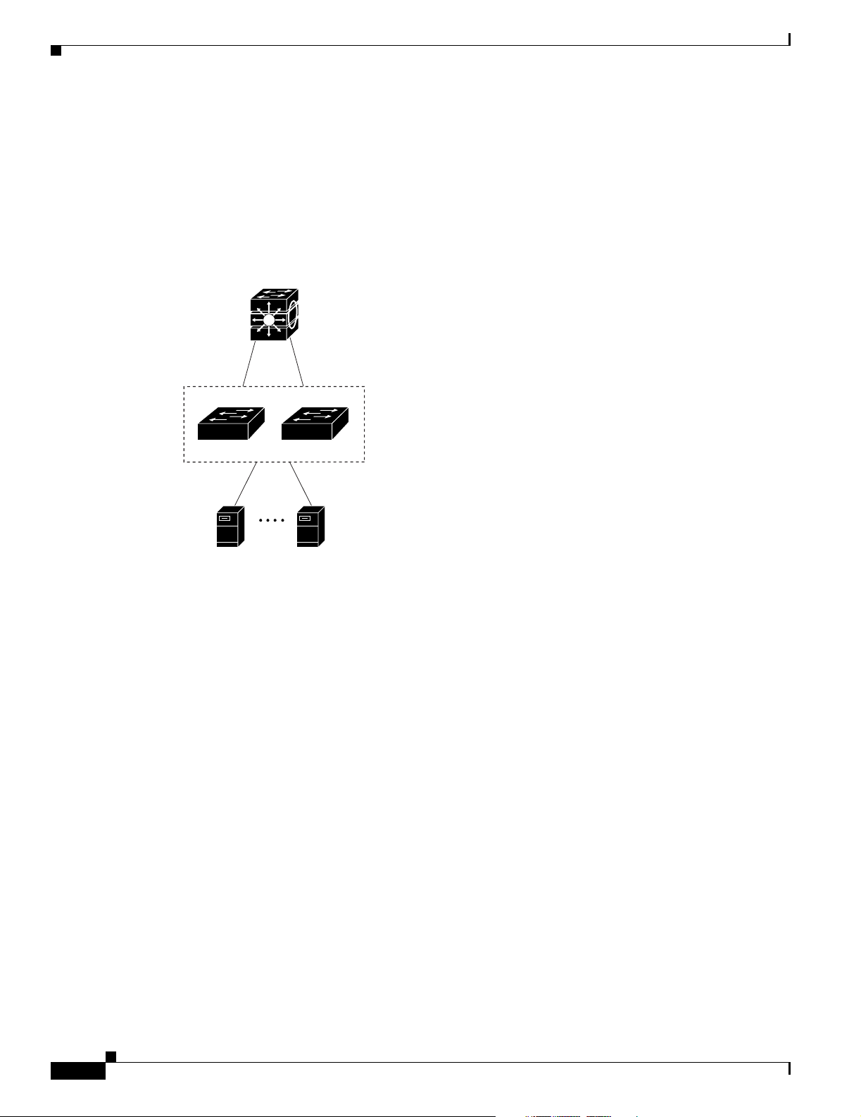
Design Concepts for Using the Switch
DSCP marking priorities on these switches. For high-speed IP forwarding at the distribution layer,
connect the switches in the access layer to a Gigabit multilayer switch with routing capability, such
as a Catalyst 3750 switch, or to a router.
The first illustration is of an isolated high-performance workgroup, where the blade switches are
connected to Catalyst 3750 switches in the distribution layer. Each blade switch in this configuration
provides users with a dedicated 1-Gbps connection to network resources. Using SFP modules also
provides flexibility in media and distance options through fiber-optic connections.
Figure 1-1 High-Performance Workgroup (Gigabit-to-the-Blade Server)
Chapter 1 Overview
Catalyst 3750
switches
Blade Switches
119954
Blade Server
•
Server aggregation (Figure 1-2)—You can use the switches to interconnect groups of servers,
Blade Server
centralizing physical security and administration of your network. For high-speed IP forwarding at
the distribution layer, connect the switches in the access layer to multilayer switches with routing
capability. The Gigabit interconnections minimize latency in the data flow.
QoS and policing on the blade switches provide preferential treatment for certain data streams. They
segment traffic streams into different paths for processing. Security features on the blade switch
ensure rapid handling of packets.
Fault tolerance from the server racks to the core is achieved through dual homing of servers
connected to the blade switches, which have redundant Gigabit EtherChannels.
Using dual SFP module uplinks from the blade switches provides redundant uplinks to the network
core. Using SFP modules provides flexibility in media and distance options through fiber-optic
connections.
1-12
Cisco Catalyst Blade Switch 3020 for HP Software Configuration Guide
OL-8915-01
Page 49
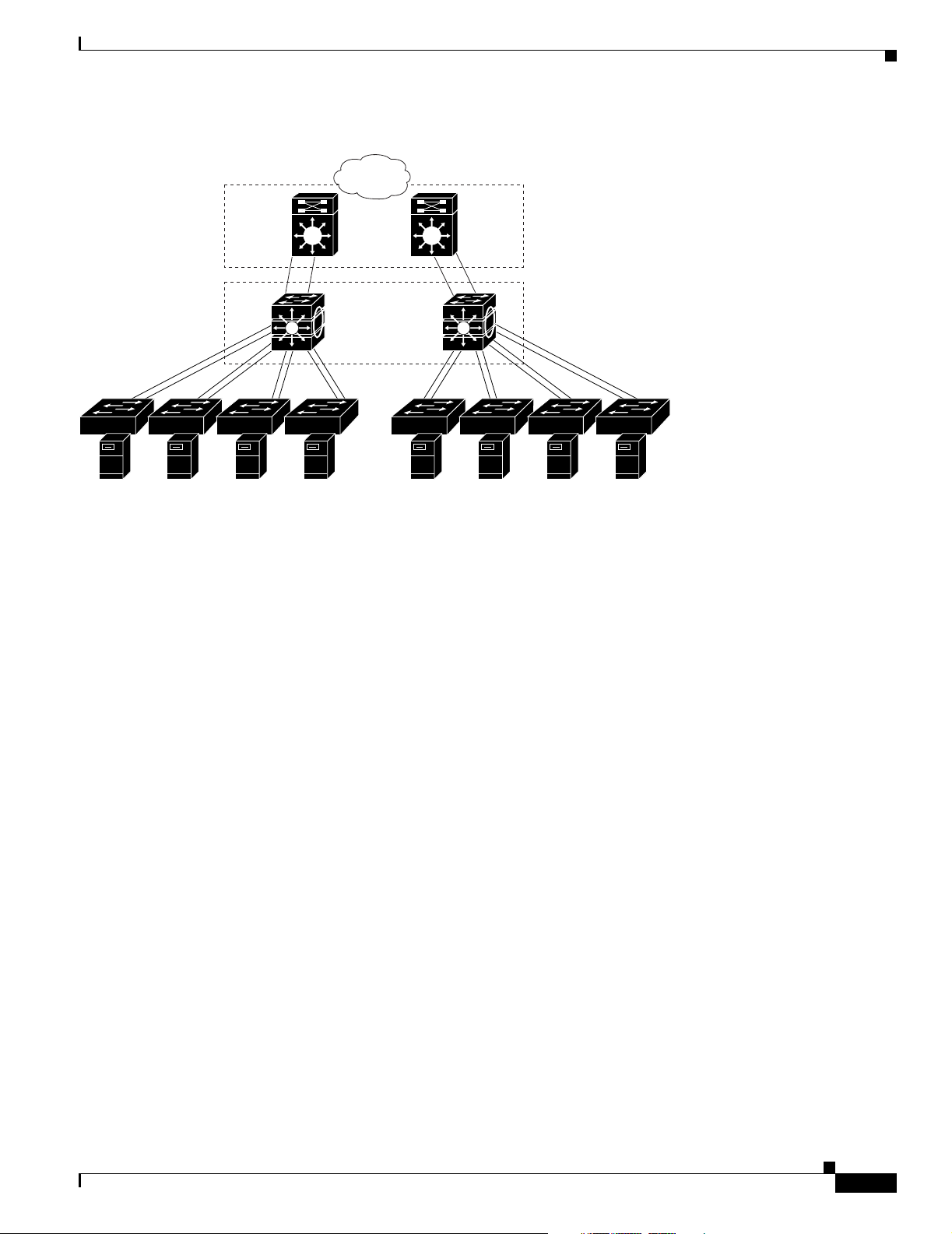
Chapter 1 Overview
Figure 1-2 Server Aggregation
Where to Go Next
Campus
core
Catalyst 6500
switches
Catalyst 3750
StackWise
switch stacks
Blade
Switches
Where to Go Next
Before configuring the switch, review these sections for startup information:
• Chapter 2, “Using the Command-Line Interface”
• Chapter 3, “Assigning the Switch IP Address and Default Gateway”
Blade
Servers
119956
OL-8915-01
Cisco Catalyst Blade Switch 3020 for HP Software Configuration Guide
1-13
Page 50

Where to Go Next
Chapter 1 Overview
1-14
Cisco Catalyst Blade Switch 3020 for HP Software Configuration Guide
OL-8915-01
Page 51

CHAPTER
2
Using the Command-Line Interface
This chapter describes the Cisco IOS command-line interface (CLI) and how to use it to configure your
switch. It contains these sections:
• Understanding Command Modes, page 2-1
• Understanding the Help System, page 2-3
• Understanding Abbreviated Commands, page 2-4
• Understanding no and default Forms of Commands, page 2-4
• Understanding CLI Error Messages, page 2-5
• Using Configuration Logging, page 2-5
• Using Command History, page 2-6
• Using Editing Features, page 2-7
• Searching and Filtering Output of show and more Commands, page 2-10
• Accessing the CLI, page 2-10
Understanding Command Modes
The Cisco IOS user interface is divided into many different modes. The commands available to you
depend on which mode you are currently in. Enter a question mark (?) at the system prompt to obtain a
list of commands available for each command mode.
When you start a session on the switch, you begin in user mode, often called user EXEC mode. Only a
limited subset of the commands are available in user EXEC mode. For example, most of the user EXEC
commands are one-time commands, such as show commands, which show the current configuration
status, and clear commands, which clear counters or interfaces. The user EXEC commands are not saved
when the switch reboots.
To have access to all commands, you must enter privileged EXEC mode. Normally, you must enter a
password to enter privileged EXEC mode. From this mode, you can enter any privileged EXEC
command or enter global configuration mode.
Using the configuration modes (global, interface, and line), you can make changes to the running
configuration. If you save the configuration, these commands are stored and used when the switch
reboots. To access the various configuration modes, you must start at global configuration mode. From
global configuration mode, you can enter interface configuration mode and line configuration mode.
OL-8915-01
Cisco Catalyst Blade Switch 3020 for HP Software Configuration Guide
2-1
Page 52

Chapter 2 Using the Command-Line Interface
Understanding Command Modes
Table 2-1 describes the main command modes, how to access each one, the prompt you see in that mode,
and how to exit the mode. The examples in the table use the hostname Switch.
Table 2-1 Command Mode Summary
Mode Access Method Prompt Exit Method About This Mode
User EXEC Begin a session with
your switch.
Privileged EXEC While in user EXEC
mode, enter the
enable command.
Global configuration While in privileged
EXEC mode, enter
the configure
command.
Config-vlan While in global
configuration mode,
enter the
vlan vlan-id
command.
VLAN configuration While in privileged
EXEC mode, enter
the vlan database
command.
Switch>
Switch#
Switch(config)#
Switch(config-vlan)#
Switch(vlan)#
Enter logout or
quit.
Enter disable to
exit.
To exit to privileged
EXEC mode, enter
exit or end, or press
Ctrl-Z.
To exit to global
configuration mode,
enter the exit
command.
To return to
privileged EXEC
mode, press Ctrl-Z
or enter end.
To exit to privileged
EXEC mode, enter
exit.
Use this mode to
• Change terminal settings.
• Perform basic tests.
• Display system
information.
Use this mode to verify
commands that you have
entered. Use a password to
protect access to this mode.
Use this mode to configure
parameters that apply to the
entire switch.
Use this mode to configure
VLAN parameters. When VTP
mode is transparent, you can
create extended-range VLANs
(VLAN IDs greater than 1005)
and save configurations in the
switch startup configuration
file.
Use this mode to configure
VLAN parameters for VLANs
1 to 1005 in the VLAN
database.
2-2
Cisco Catalyst Blade Switch 3020 for HP Software Configuration Guide
OL-8915-01
Page 53

Chapter 2 Using the Command-Line Interface
Understanding the Help System
Table 2-1 Command Mode Summary (continued)
Mode Access Method Prompt Exit Method About This Mode
Interface
configuration
While in global
configuration mode,
enter the interface
command (with a
specific interface).
Line configuration While in global
configuration mode,
specify a line with
the line vty or line
console command.
Switch(config-if)#
Switch(config-line)#
To exit to global
configuration mode,
enter exit.
To return to
privileged EXEC
mode, press Ctrl-Z
or enter end.
To exit to global
configuration mode,
enter exit.
To return to
privileged EXEC
mode, press Ctrl-Z
or enter end.
Use this mode to configure
parameters for the Ethernet
ports.
For information about defining
interfaces, see the “Using
Interface Configuration Mode”
section on page 8-6.
To configure multiple
interfaces with the same
parameters, see the
“Configuring a Range of
Interfaces” section on
page 8-7.
Use this mode to configure
parameters for the terminal
line.
For more detailed information on the command modes, see the Cisco Catalyst Blade Switch 3020
Command Reference for this release.
Understanding the Help System
You can enter a question mark (?) at the system prompt to display a list of commands available for each
command mode. You can also obtain a list of associated keywords and arguments for any command, as
shown in Table 2-2 .
Ta b l e 2 -2 H e l p S u m m a r y
Command Purpose
help Obtain a brief description of the help system in any command mode.
abbreviated-command-entry? Obtain a list of commands that begin with a particular character string.
For example:
Switch# di?
dir disable disconnect
abbreviated-command-entry<Ta b> Complete a partial command name.
For example:
Switch# sh conf<tab>
Switch# show configuration
OL-8915-01
Cisco Catalyst Blade Switch 3020 for HP Software Configuration Guide
2-3
Page 54

Chapter 2 Using the Command-Line Interface
Understanding Abbreviated Commands
Table 2-2 Help Summary (continued)
Command Purpose
? List all commands available for a particular command mode.
For example:
Switch> ?
command ? List the associated keywords for a command.
For example:
Switch> show ?
command keyword ? List the associated arguments for a keyword.
For example:
Switch(config)# cdp holdtime ?
<10-255> Length of time (in sec) that receiver must keep this packet
Understanding Abbreviated Commands
You need to enter only enough characters for the switch to recognize the command as unique.
This example shows how to enter the show configuration privileged EXEC command in an abbreviated
form:
Switch# show conf
Understanding no and default Forms of Commands
Almost every configuration command also has a no form. In general, use the no form to disable a feature
or function or reverse the action of a command. For example, the no shutdown interface configuration
command reverses the shutdown of an interface. Use the command without the keyword no to re-enable
a disabled feature or to enable a feature that is disabled by default.
Configuration commands can also have a default form. The default form of a command returns the
command setting to its default. Most commands are disabled by default, so the default form is the same
as the no form. However, some commands are enabled by default and have variables set to certain default
values. In these cases, the default command enables the command and sets variables to their default
values.
2-4
Cisco Catalyst Blade Switch 3020 for HP Software Configuration Guide
OL-8915-01
Page 55

Chapter 2 Using the Command-Line Interface
Understanding CLI Error Messages
Table 2-3 lists some error messages that you might encounter while using the CLI to configure your
switch.
Table 2-3 Common CLI Error Messages
Error Message Meaning How to Get Help
% Ambiguous command:
"show con"
% Incomplete command.
% Invalid input detected
at ‘^’ marker.
You did not enter enough characters
for your switch to recognize the
command.
You did not enter all the keywords or
values required by this command.
You entered the command
incorrectly. The caret (^) marks the
point of the error.
Re-enter the command followed by a question mark (?)
with a space between the command and the question
mark.
The possible keywords that you can enter with the
command appear.
Re-enter the command followed by a question mark (?)
with a space between the command and the question
mark.
The possible keywords that you can enter with the
command appear.
Enter a question mark (?) to display all the commands
that are available in this command mode.
The possible keywords that you can enter with the
command appear.
Understanding CLI Error Messages
Using Configuration Logging
You can log and view changes to the switch configuration. You can use the Configuration Change
Logging and Notification feature to track changes on a per-session and per-user basis. The logger tracks
each configuration command that is applied, the user who entered the command, the time that the
command was entered, and the parser return code for the command. This feature includes a mechanism
for asynchronous notification to registered applications whenever the configuration changes. You can
choose to have the notifications sent to the syslog.
For more information, see the Configuration Change Notification and Logging feature module at this
URL:
http://www.cisco.com/univercd/cc/td/doc/product/software/ios123/123newft/123t/123t_4/
gtconlog.htm
Note Only CLI or HTTP changes are logged.
OL-8915-01
Cisco Catalyst Blade Switch 3020 for HP Software Configuration Guide
2-5
Page 56

Using Command History
Using Command History
The software provides a history or record of commands that you have entered. The command history
feature is particularly useful for recalling long or complex commands or entries, including access lists.
You can customize this feature to suit your needs as described in these sections:
• Changing the Command History Buffer Size, page 2-6 (optional)
• Recalling Commands, page 2-6 (optional)
• Disabling the Command History Feature, page 2-7 (optional)
Changing the Command History Buffer Size
By default, the switch records ten command lines in its history buffer. You can alter this number for a
current terminal session or for all sessions on a particular line. These procedures are optional.
Beginning in privileged EXEC mode, enter this command to change the number of command lines that
the switch records during the current terminal session:
Switch# terminal history [size
number-of-lines
Chapter 2 Using the Command-Line Interface
]
The range is from 0 to 256.
Beginning in line configuration mode, enter this command to configure the number of command lines
the switch records for all sessions on a particular line:
Switch(config-line)# history [size
The range is from 0 to 256.
number-of-lines
]
Recalling Commands
To recall commands from the history buffer, perform one of the actions listed in Ta ble 2 -4. These actions
are optional.
Table 2-4 Recalling Commands
1
Action
Press Ctrl-P or the up arrow key. Recall commands in the history buffer, beginning with the most recent command.
Press Ctrl-N or the down arrow key. Return to more recent commands in the history buffer after recalling commands
show history While in privileged EXEC mode, list the last several commands that you just
1. The arrow keys function only on ANSI-compatible terminals such as VT100s.
Result
Repeat the key sequence to recall successively older commands.
with Ctrl-P or the up arrow key. Repeat the key sequence to recall successively
more recent commands.
entered. The number of commands that appear is controlled by the setting of the
terminal history global configuration command and the history line configuration
command.
2-6
Cisco Catalyst Blade Switch 3020 for HP Software Configuration Guide
OL-8915-01
Page 57

Chapter 2 Using the Command-Line Interface
Disabling the Command History Feature
The command history feature is automatically enabled. You can disable it for the current terminal session
or for the command line. These procedures are optional.
To disable the feature during the current terminal session, enter the terminal no history privileged
EXEC command.
To disable command history for the line, enter the no history line configuration command.
Using Editing Features
This section describes the editing features that can help you manipulate the command line. It contains
these sections:
• Enabling and Disabling Editing Features, page 2-7 (optional)
• Editing Commands through Keystrokes, page 2-7 (optional)
• Editing Command Lines that Wrap, page 2-9 (optional)
Using Editing Features
Enabling and Disabling Editing Features
Although enhanced editing mode is automatically enabled, you can disable it, re-enable it, or configure
a specific line to have enhanced editing. These procedures are optional.
To globally disable enhanced editing mode, enter this command in line configuration mode:
Switch (config-line)# no editing
To re-enable the enhanced editing mode for the current terminal session, enter this command in
privileged EXEC mode:
Switch# terminal editing
To reconfigure a specific line to have enhanced editing mode, enter this command in line configuration
mode:
Switch(config-line)# editing
Editing Commands through Keystrokes
Table 2-5 shows the keystrokes that you need to edit command lines. These keystrokes are optional.
Table 2-5 Editing Commands through Keystrokes
Capability Keystroke
Move around the command line to
make changes or corrections.
Press Ctrl-B, or press the
left arrow key.
1
Purpose
Move the cursor back one character.
OL-8915-01
Cisco Catalyst Blade Switch 3020 for HP Software Configuration Guide
2-7
Page 58

Using Editing Features
Table 2-5 Editing Commands through Keystrokes (continued)
Chapter 2 Using the Command-Line Interface
Capability Keystroke
Press Ctrl-F, or press the
right arrow key.
Press Ctrl-A. Move the cursor to the beginning of the command line.
Press Ctrl-E. Move the cursor to the end of the command line.
Press Esc B. Move the cursor back one word.
Press Esc F. Move the cursor forward one word.
Press Ctrl-T. Transpose the character to the left of the cursor with the
Recall commands from the buffer and
Press Ctrl-Y. Recall the most recent entry in the buffer.
paste them in the command line. The
switch provides a buffer with the last
ten items that you deleted.
Press Esc Y. Recall the next buffer entry.
Delete entries if you make a mistake
or change your mind.
Press the Delete or
Backspace key.
Press Ctrl-D. Delete the character at the cursor.
Press Ctrl-K. Delete all characters from the cursor to the end of the
Press Ctrl-U or Ctrl-X. Delete all characters from the cursor to the beginning of
Press Ctrl-W. Delete the word to the left of the cursor.
Press Esc D. Delete from the cursor to the end of the word.
Capitalize or lowercase words or
Press Esc C. Capitalize at the cursor.
capitalize a set of letters.
Press Esc L. Change the word at the cursor to lowercase.
Press Esc U. Capitalize letters from the cursor to the end of the word.
Designate a particular keystroke as
Press Ctrl-V or Esc Q.
an executable command, perhaps as a
shortcut.
1
Purpose
Move the cursor forward one character.
character located at the cursor.
The buffer contains only the last 10 items that you have
deleted or cut. If you press Esc Y more than ten times, you
cycle to the first buffer entry.
Erase the character to the left of the cursor.
command line.
the command line.
2-8
Cisco Catalyst Blade Switch 3020 for HP Software Configuration Guide
OL-8915-01
Page 59

Chapter 2 Using the Command-Line Interface
Table 2-5 Editing Commands through Keystrokes (continued)
Using Editing Features
Capability Keystroke
Scroll down a line or screen on
Press the Return key. Scroll down one line.
1
displays that are longer than the
terminal screen can display.
Note The More prompt is used for
any output that has more
lines than can be displayed
on the terminal screen,
including show command
output. You can use the
Return and Space bar
keystrokes whenever you see
the More prompt.
Press the Space bar. Scroll down one screen.
Redisplay the current command line
Press Ctrl-L or Ctrl-R. Redisplay the current command line.
if the switch suddenly sends a
message to your screen.
1. The arrow keys function only on ANSI-compatible terminals such as VT100s.
Editing Command Lines that Wrap
Purpose
You can use a wraparound feature for commands that extend beyond a single line on the screen. When
the cursor reaches the right margin, the command line shifts ten spaces to the left. You cannot see the
first ten characters of the line, but you can scroll back and check the syntax at the beginning of the
command. The keystroke actions are optional.
To scroll back to the beginning of the command entry, press Ctrl-B or the left arrow key repeatedly. You
can also press Ctrl-A to immediately move to the beginning of the line.
The arrow keys function only on ANSI-compatible terminals such as VT100s.
In this example, the access-list global configuration command entry extends beyond one line. When the
cursor first reaches the end of the line, the line is shifted ten spaces to the left and redisplayed. The dollar
sign ($) shows that the line has been scrolled to the left. Each time the cursor reaches the end of the line,
the line is again shifted ten spaces to the left.
Switch(config)# access-list 101 permit tcp 131.108.2.5 255.255.255.0 131.108.1
Switch(config)# $ 101 permit tcp 131.108.2.5 255.255.255.0 131.108.1.20 255.25
Switch(config)# $t tcp 131.108.2.5 255.255.255.0 131.108.1.20 255.255.255.0 eq
Switch(config)# $108.2.5 255.255.255.0 131.108.1.20 255.255.255.0 eq 45
After you complete the entry, press Ctrl-A to check the complete syntax before pressing the Return key
to execute the command. The dollar sign ($) appears at the end of the line to show that the line has been
scrolled to the right:
Switch(config)# access-list 101 permit tcp 131.108.2.5 255.255.255.0 131.108.1$
The software assumes you have a terminal screen that is 80 columns wide. If you have a width other than
that, use the terminal width privileged EXEC command to set the width of your terminal.
OL-8915-01
Use line wrapping with the command history feature to recall and modify previous complex command
entries. For information about recalling previous command entries, see the “Editing Commands through
Keystrokes” section on page 2-7.
Cisco Catalyst Blade Switch 3020 for HP Software Configuration Guide
2-9
Page 60

Chapter 2 Using the Command-Line Interface
Searching and Filtering Output of show and more Commands
Searching and Filtering Output of show and more Commands
You can search and filter the output for show and more commands. This is useful when you need to sort
through large amounts of output or if you want to exclude output that you do not need to see. Using these
commands is optional.
To use this functionality, enter a show or more command followed by the pipe character (|), one of the
keywords begin, include, or exclude, and an expression that you want to search for or filter out:
command | {begin | include | exclude} regular-expression
Expressions are case sensitive. For example, if you enter | exclude output, the lines that contain output
are not displayed, but the lines that contain Output appear.
This example shows how to include in the output display only lines where the expression protocol
appears:
Switch# show interfaces | include protocol
Vlan1 is up, line protocol is up
Vlan10 is up, line protocol is down
GigabitEthernet0/1 is up, line protocol is down
GigabitEthernet0/2 is up, line protocol is up
Accessing the CLI
You can access the CLI through a console connection, through Telnet, or by using the browser.
Accessing the CLI through a Console Connection or through Telnet
Before you can access the CLI, you must connect a terminal or PC to the switch console port and power
on the switch, as described in the Cisco Catalyst Blade Switch 3020 Getting Started Guide that shipped
with your switch. Then, to understand the boot process and the options available for assigning IP
information, see Chapter 3, “Assigning the Switch IP Address and Default Gateway.”
If your switch is already configured, you can access the CLI through a local console connection or
through a remote Telnet session, but your switch must first be configured for this type of access. For
more information, see the “Setting a Telnet Password for a Terminal Line” section on page 6-6.
You can use one of these methods to establish a connection with the switch:
• Connect the switch console port to a management station or dial-up modem. For information about
connecting to the console port, see the switch hardware installation guide.
• Use any Telnet TCP/IP or encrypted Secure Shell (SSH) package from a remote management
station. The switch must have network connectivity with the Telnet or SSH client, and the switch
must have an enable secret password configured.
2-10
Cisco Catalyst Blade Switch 3020 for HP Software Configuration Guide
OL-8915-01
Page 61

Chapter 2 Using the Command-Line Interface
For information about configuring the switch for Telnet access, see the “Setting a Telnet Password
for a Terminal Line” section on page 6-6. The switch supports up to 16 simultaneous Telnet sessions.
Changes made by one Telnet user are reflected in all other Telnet sessions.
For information about configuring the switch for SSH, see the “Configuring the Switch for Secure
Shell” section on page 6-37. The switch supports up to five simultaneous secure SSH sessions.
After you connect through the console port, through a Telnet session or through an SSH session, the
user EXEC prompt appears on the management station.
Accessing the CLI
OL-8915-01
Cisco Catalyst Blade Switch 3020 for HP Software Configuration Guide
2-11
Page 62

Accessing the CLI
Chapter 2 Using the Command-Line Interface
2-12
Cisco Catalyst Blade Switch 3020 for HP Software Configuration Guide
OL-8915-01
Page 63

CHAPTER
3
Assigning the Switch IP Address and Default Gateway
This chapter describes how to create the initial switch configuration (for example, assigning the IP
address and default gateway information) by using a variety of automatic and manual methods. It also
describes how to modify the switch startup configuration.
Note For complete syntax and usage information for the commands used in this chapter, see the Cisco Catalyst
Blade Switch 3020 for HP Command Reference for this release and the Cisco IOS IP Command
Reference, Volume 1 of 3: Addressing and Services, Release 12.2.
This chapter consists of these sections:
• Understanding the Boot Process, page 3-1
• Assigning Switch Information, page 3-2
• Checking and Saving the Running Configuration, page 3-10
• Modifying the Startup Configuration, page 3-13
• Scheduling a Reload of the Software Image, page 3-18
Understanding the Boot Process
To start your switch, you need to follow the procedures in the Cisco Catalyst Blade Switch 3020 for HP
Getting Started Guide or the Cisco Catalyst Blade Switch 3020 for HP Hardware Installation Guide for
installing the switch and setting up the initial switch configuration (IP address, subnet mask, default
gateway, secret and Telnet passwords, and so forth).
The normal boot process involves the operation of the boot loader software, which performs these
activities:
• Performs low-level CPU initialization. It initializes the CPU registers, which control where physical
memory is mapped, its quantity, its speed, and so forth.
• Performs power-on self-test (POST) for the CPU subsystem. It tests the CPU DRAM and the portion
of the flash device that makes up the flash file system.
• Initializes the flash file system on the system board.
• Loads a default operating system software image into memory and boots the switch.
OL-8915-01
Cisco Catalyst Blade Switch 3020 for HP Software Configuration Guide
3-1
Page 64

Assigning Switch Information
The boot loader provides access to the flash file system before the operating system is loaded. Normally,
the boot loader is used only to load, uncompress, and launch the operating system. After the boot loader
gives the operating system control of the CPU, the boot loader is not active until the next system reset
or power-on.
The boot loader also provides trap-door access into the system if the operating system has problems
serious enough that it cannot be used. The trap-door mechanism provides enough access to the system
so that if it is necessary, you can format the flash file system, reinstall the operating system software
image by using the Xmodem Protocol, recover from a lost or forgotten password, and finally restart the
operating system. For more information, see the “Recovering from a Software Failure” section on
page 29-2 and the “Recovering from a Lost or Forgotten Password” section on page 29-3.
Note You can disable password recovery. For more information, see the “Disabling Password Recovery”
section on page 6-5.
Before you can assign switch information, make sure you have connected a PC or terminal to the console
port, and configured the PC or terminal-emulation software baud rate and character format to match
these of the switch console port:
• Baud rate default is 9600.
Chapter 3 Assigning the Switch IP Address and Default Gateway
• Data bits default is 8.
Note If the data bits option is set to 8, set the parity option to none.
• Stop bits default is 1.
• Parity settings default is none.
Assigning Switch Information
You can assign IP information through the switch setup program, through a DHCP server, or manually.
Use the switch setup program if you want to be prompted for specific IP information. With this program,
you can also configure a hostname and an enable secret password. It gives you the option of assigning a
Telnet password (to provide security during remote management) and configuring your switch as a
standalone switch. For more information about the setup program, see the hardware installation guide.
Use a DHCP server for centralized control and automatic assignment of IP information after the server
is configured.
Note If you are using DHCP, do not respond to any of the questions in the setup program until the switch
receives the dynamically assigned IP address and reads the configuration file.
3-2
If you are an experienced user familiar with the switch configuration steps, manually configure the
switch. Otherwise, use the setup program described previously.
These sections contain this configuration information:
• Default Switch Information, page 3-3
• Understanding DHCP-Based Autoconfiguration, page 3-3
• Manually Assigning IP Information, page 3-10
Cisco Catalyst Blade Switch 3020 for HP Software Configuration Guide
OL-8915-01
Page 65

Chapter 3 Assigning the Switch IP Address and Default Gateway
Default Switch Information
Table 3-1 shows the default switch information.
Table 3-1 Default Switch Information
Feature Default Setting
IP address and subnet mask No IP address or subnet mask are defined.
Default gateway No default gateway is defined.
Enable secret password No password is defined.
Hostname The factory-assigned default hostname is Switch.
Telnet password No password is defined.
Understanding DHCP-Based Autoconfiguration
DHCP provides configuration information to Internet hosts and internetworking devices. This protocol
consists of two components: one for delivering configuration parameters from a DHCP server to a device
and a mechanism for allocating network addresses to devices. DHCP is built on a client-server model,
in which designated DHCP servers allocate network addresses and deliver configuration parameters to
dynamically configured devices. The switch can act as both a DHCP client and a DHCP server.
During DHCP-based autoconfiguration, your switch (DHCP client) is automatically configured at
startup with IP address information and a configuration file.
Assigning Switch Information
With DHCP-based autoconfiguration, no DHCP client-side configuration is needed on your switch.
However, you need to configure the DHCP server for various lease options associated with IP addresses.
If you are using DHCP to relay the configuration file location on the network, you might also need to
configure a Trivial File Transfer Protocol (TFTP) server and a Domain Name System (DNS) server.
The DHCP server for your switch can be on the same LAN or on a different LAN than the switch. If the
DHCP server is running on a different LAN, you should configure a DHCP relay device between your
switch and the DHCP server. A relay device forwards broadcast traffic between two directly connected
LANs. A router does not forward broadcast packets, but it forwards packets based on the destination IP
address in the received packet.
DHCP-based autoconfiguration replaces the BOOTP client functionality on your switch.
When you install the switch, the HP Onboard Administrator might assign an IP address to the switch fa0
Ethernet interface. This occurs if the Onboard Administrator is connected to a network in which a DHCP
server is also connected or if the Onboard Administrator has been configured as a DHCP server. If either
of these conditions is true, the fa0 interface obtains an IP address, and you can manage the switch
through the fa0 interface. See the HP BladeSystem documentation at
http://www.hp.com/go/bladesystem/documentation for more information about the Onboard
Administrator.
OL-8915-01
Cisco Catalyst Blade Switch 3020 for HP Software Configuration Guide
3-3
Page 66

Assigning Switch Information
DHCP Client Request Process
When you boot your switch, the DHCP client is invoked and requests configuration information from a
DHCP server when the configuration file is not present on the switch. If the configuration file is present
and the configuration includes the ip address dhcp interface configuration command on specific routed
interfaces, the DHCP client is invoked and requests the IP address information for those interfaces.
Figure 3-1 shows the sequence of messages that are exchanged between the DHCP client and the DHCP
server.
Figure 3-1 DHCP Client and Server Message Exchange
Switch A
The client, Switch A, broadcasts a DHCPDISCOVER message to locate a DHCP server. The DHCP
server offers configuration parameters (such as an IP address, subnet mask, gateway IP address, DNS IP
address, a lease for the IP address, and so forth) to the client in a DHCPOFFER unicast message.
DHCPDISCOVER (broadcast)
DHCPOFFER (unicast)
DHCPREQUEST (broadcast)
DHCPACK (unicast)
Chapter 3 Assigning the Switch IP Address and Default Gateway
DHCP server
51807
In a DHCPREQUEST broadcast message, the client returns a formal request for the offered
configuration information to the DHCP server. The formal request is broadcast so that all other DHCP
servers that received the DHCPDISCOVER broadcast message from the client can reclaim the IP
addresses that they offered to the client.
The DHCP server confirms that the IP address has been allocated to the client by returning a DHCPACK
unicast message to the client. With this message, the client and server are bound, and the client uses
configuration information received from the server. The amount of information the switch receives
depends on how you configure the DHCP server. For more information, see the “Configuring the TFTP
Server” section on page 3-6.
If the configuration parameters sent to the client in the DHCPOFFER unicast message are invalid (a
configuration error exists), the client returns a DHCPDECLINE broadcast message to the DHCP server.
The DHCP server sends the client a DHCPNAK denial broadcast message, which means that the offered
configuration parameters have not been assigned, that an error has occurred during the negotiation of the
parameters, or that the client has been slow in responding to the DHCPOFFER message (the DHCP
server assigned the parameters to another client).
A DHCP client might receive offers from multiple DHCP or BOOTP servers and can accept any of the
offers; however, the client usually accepts the first offer it receives. The offer from the DHCP server is
not a guarantee that the IP address is allocated to the client; however, the server usually reserves the
address until the client has had a chance to formally request the address. If the switch accepts replies
from a BOOTP server and configures itself, the switch broadcasts, instead of unicasts, TFTP requests to
obtain the switch configuration file.
3-4
Cisco Catalyst Blade Switch 3020 for HP Software Configuration Guide
OL-8915-01
Page 67

Chapter 3 Assigning the Switch IP Address and Default Gateway
Configuring DHCP-Based Autoconfiguration
These sections contain this configuration information:
• DHCP Server Configuration Guidelines, page 3-5
• Configuring the TFTP Server, page 3-6
• Configuring the DNS, page 3-6
• Configuring the Relay Device, page 3-6
• Obtaining Configuration Files, page 3-7
• Example Configuration, page 3-8
If your DHCP server is a Cisco device, see the “Configuring DHCP” section of the “IP Addressing and
Services” section of the Cisco IOS IP Configuration Guide, Release 12.2 for additional information
about configuring DHCP.
DHCP Server Configuration Guidelines
Follow these guidelines if you are configuring a device as a DHCP server:
Assigning Switch Information
You should configure the DHCP server with reserved leases that are bound to each switch by the switch
hardware address.
If you want the switch to receive IP address information, you must configure the DHCP server with these
lease options:
• IP address of the client (required)
• Subnet mask of the client (required)
• DNS server IP address (optional)
• Router IP address (default gateway address to be used by the switch) (required)
If you want the switch to receive the configuration file from a TFTP server, you must configure the
DHCP server with these lease options:
• TFTP server name (required)
• Boot filename (the name of the configuration file that the client needs) (recommended)
• Hostname (optional)
Depending on the settings of the DHCP server, the switch can receive IP address information, the
configuration file, or both.
If you do not configure the DHCP server with the lease options described previously, it replies to client
requests with only those parameters that are configured. If the IP address and the subnet mask are not in
the reply, the switch is not configured. If the router IP address or the TFTP server name are not found,
the switch might send broadcast, instead of unicast, TFTP requests. Unavailability of other lease options
does not affect autoconfiguration.
OL-8915-01
Cisco Catalyst Blade Switch 3020 for HP Software Configuration Guide
3-5
Page 68

Assigning Switch Information
Configuring the TFTP Server
Based on the DHCP server configuration, the switch attempts to download one or more configuration
files from the TFTP server. If you configured the DHCP server to respond to the switch with all the
options required for IP connectivity to the TFTP server, and if you configured the DHCP server with a
TFTP server name, address, and configuration filename, the switch attempts to download the specified
configuration file from the specified TFTP server.
If you did not specify the configuration filename, the TFTP server, or if the configuration file could not
be downloaded, the switch attempts to download a configuration file by using various combinations of
filenames and TFTP server addresses. The files include the specified configuration filename (if any) and
these files: network-config, cisconet.cfg, hostname.config, or hostname.cfg, where hostname is the
switch’s current hostname. The TFTP server addresses used include the specified TFTP server address
(if any) and the broadcast address (255.255.255.255).
For the switch to successfully download a configuration file, the TFTP server must contain one or more
configuration files in its base directory. The files can include these files:
• The configuration file named in the DHCP reply (the actual switch configuration file).
• The network-confg or the cisconet.cfg file (known as the default configuration files).
• The router-confg or the ciscortr.cfg file (These files contain commands common to all switches.
Normally, if the DHCP and TFTP servers are properly configured, these files are not accessed.)
Chapter 3 Assigning the Switch IP Address and Default Gateway
If you specify the TFTP server name in the DHCP server-lease database, you must also configure the
TFTP server name-to-IP-address mapping in the DNS-server database.
If the TFTP server to be used is on a different LAN from the switch, or if it is to be accessed by the switch
through the broadcast address (which occurs if the DHCP server response does not contain all the
required information described previously), a relay must be configured to forward the TFTP packets to
the TFTP server. For more information, see the “Configuring the Relay Device” section on page 3-6. The
preferred solution is to configure the DHCP server with all the required information.
Configuring the DNS
The DHCP server uses the DNS server to resolve the TFTP server name to an IP address. You must
configure the TFTP server name-to-IP address map on the DNS server. The TFTP server contains the
configuration files for the switch.
You can configure the IP addresses of the DNS servers in the lease database of the DHCP server from
where the DHCP replies will retrieve them. You can enter up to two DNS server IP addresses in the lease
database.
The DNS server can be on the same or on a different LAN as the switch. If it is on a different LAN, the
switch must be able to access it through a router.
Configuring the Relay Device
You must configure a relay device, also referred to as a relay agent, when a switch sends broadcast
packets that require a response from a host on a different LAN. Examples of broadcast packets that the
switch might send are DHCP, DNS, and in some cases, TFTP packets. You must configure this relay
device to forward received broadcast packets on an interface to the destination host.
3-6
If the relay device is a Cisco router, enable IP routing (ip routing global configuration command), and
configure helper addresses by using the ip helper-address interface configuration command.
Cisco Catalyst Blade Switch 3020 for HP Software Configuration Guide
OL-8915-01
Page 69

Chapter 3 Assigning the Switch IP Address and Default Gateway
For example, in Figure 3-2, configure the router interfaces as follows:
On interface 10.0.0.2:
router(config-if)# ip helper-address 20.0.0.2
router(config-if)# ip helper-address 20.0.0.3
router(config-if)# ip helper-address 20.0.0.4
On interface 20.0.0.1
router(config-if)# ip helper-address 10.0.0.1
Figure 3-2 Relay Device Used in Autoconfiguration
Assigning Switch Information
Switch
(DHCP client)
10.0.0.1
20.0.0.2 20.0.0.3
DHCP server TFTP server DNS server
Obtaining Configuration Files
Depending on the availability of the IP address and the configuration filename in the DHCP reserved
lease, the switch obtains its configuration information in these ways:
• The IP address and the configuration filename is reserved for the switch and provided in the DHCP
reply (one-file read method).
The switch receives its IP address, subnet mask, TFTP server address, and the configuration
filename from the DHCP server. The switch sends a unicast message to the TFTP server to retrieve
the named configuration file from the base directory of the server and upon receipt, it completes its
boot-up process.
Cisco router
(Relay)
10.0.0.2
20.0.0.1
20.0.0.4
49068
OL-8915-01
• The IP address and the configuration filename is reserved for the switch, but the TFTP server
address is not provided in the DHCP reply (one-file read method).
The switch receives its IP address, subnet mask, and the configuration filename from the DHCP
server. The switch sends a broadcast message to a TFTP server to retrieve the named configuration
file from the base directory of the server, and upon receipt, it completes its boot-up process.
• Only the IP address is reserved for the switch and provided in the DHCP reply. The configuration
filename is not provided (two-file read method).
The switch receives its IP address, subnet mask, and the TFTP server address from the DHCP server.
The switch sends a unicast message to the TFTP server to retrieve the network-confg or cisconet.cfg
default configuration file. (If the network-confg file cannot be read, the switch reads the cisconet.cfg
file.)
Cisco Catalyst Blade Switch 3020 for HP Software Configuration Guide
3-7
Page 70
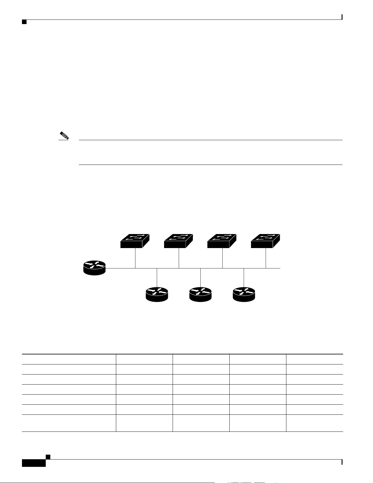
Assigning Switch Information
The default configuration file contains the hostnames-to-IP-address mapping for the switch. The
switch fills its host table with the information in the file and obtains its hostname. If the hostname
is not found in the file, the switch uses the hostname in the DHCP reply. If the hostname is not
specified in the DHCP reply, the switch uses the default Switch as its hostname.
After obtaining its hostname from the default configuration file or the DHCP reply, the switch reads
the configuration file that has the same name as its hostname (hostname-confg or hostname.cfg,
depending on whether network-confg or cisconet.cfg was read earlier) from the TFTP server. If the
cisconet.cfg file is read, the filename of the host is truncated to eight characters.
If the switch cannot read the network-confg, cisconet.cfg, or the hostname file, it reads the
router-confg file. If the switch cannot read the router-confg file, it reads the ciscortr.cfg file.
Note The switch broadcasts TFTP server requests if the TFTP server is not obtained from the DHCP replies,
if all attempts to read the configuration file through unicast transmissions fail, or if the TFTP server
name cannot be resolved to an IP address.
Example Configuration
Chapter 3 Assigning the Switch IP Address and Default Gateway
Figure 3-3 shows a sample network for retrieving IP information by using DHCP-based autoconfiguration.
Figure 3-3 DHCP-Based Autoconfiguration Network Example
Switch 1
00e0.9f1e.2001
Cisco router
10.0.0.10
DHCP server DNS server TFTP server
Switch 2
00e0.9f1e.2002
10.0.0.1
Switch 3
00e0.9f1e.2003
10.0.0.2 10.0.0.3
(tftpserver)
Switch 4
00e0.9f1e.2004
111394
Table 3-2 shows the configuration of the reserved leases on the DHCP server.
Table 3-2 DHCP Server Configuration
Switch A Switch B Switch C Switch D
Binding key (hardware address) 00e0.9f1e.2001 00e0.9f1e.2002 00e0.9f1e.2003 00e0.9f1e.2004
IP address 10.0.0.21 10.0.0.22 10.0.0.23 10.0.0.24
Subnet mask 255.255.255.0 255.255.255.0 255.255.255.0 255.255.255.0
Router address 10.0.0.10 10.0.0.10 10.0.0.10 10.0.0.10
DNS server address 10.0.0.2 10.0.0.2 10.0.0.2 10.0.0.2
TFTP server name tftpserver or
10.0.0.3
tftpserver or
10.0.0.3
tftpserver or
10.0.0.3
tftpserver or
10.0.0.3
3-8
Cisco Catalyst Blade Switch 3020 for HP Software Configuration Guide
OL-8915-01
Page 71

Chapter 3 Assigning the Switch IP Address and Default Gateway
Assigning Switch Information
Table 3-2 DHCP Server Configuration (continued)
Switch A Switch B Switch C Switch D
Boot filename (configuration file)
(optional)
Hostname (optional) switcha switchb switchc switchd
DNS Server Configuration
The DNS server maps the TFTP server name tftpserver to IP address 10.0.0.3.
TFTP Server Configuration (on UNIX)
The TFTP server base directory is set to /tftpserver/work/. This directory contains the network-confg file
used in the two-file read method. This file contains the hostname to be assigned to the switch based on
its IP address. The base directory also contains a configuration file for each switch (switcha-confg,
switchb-confg, and so forth) as shown in this display:
prompt> cd /tftpserver/work/
prompt> ls
network-confg
switcha-confg
switchb-confg
switchc-confg
switchd-confg
prompt> cat network-confg
ip host switcha 10.0.0.21
ip host switchb 10.0.0.22
ip host switchc 10.0.0.23
ip host switchd 10.0.0.24
switcha-confg switchb-confg switchc-confg switchd-confg
DHCP Client Configuration
No configuration file is present on Switch A through Switch D.
Configuration Explanation
In Figure 3-3, Switch A reads its configuration file as follows:
• It obtains its IP address 10.0.0.21 from the DHCP server.
• If no configuration filename is given in the DHCP server reply, Switch A reads the network-confg
file from the base directory of the TFTP server.
• It adds the contents of the network-confg file to its host table.
• It reads its host table by indexing its IP address 10.0.0.21 to its hostname (switcha).
• It reads the configuration file that corresponds to its hostname; for example, it reads switch1-confg
from the TFTP server.
Switches B through D retrieve their configuration files and IP addresses in the same way.
OL-8915-01
Cisco Catalyst Blade Switch 3020 for HP Software Configuration Guide
3-9
Page 72

Checking and Saving the Running Configuration
Manually Assigning IP Information
Beginning in privileged EXEC mode, follow these steps to manually assign IP information to multiple
switched virtual interfaces (SVIs):
Command Purpose
Step 1
Step 2
Step 3
Step 4
Step 5
configure terminal Enter global configuration mode.
interface vlan vlan-id Enter interface configuration mode, and enter the VLAN to which the IP
information is assigned. The VLAN range is 1 to 4094. The fa0 interface
can be used instead of the VLAN interface.
ip address ip-address subnet-mask Enter the IP address and subnet mask.
exit Return to global configuration mode.
ip default-gateway ip-address Enter the IP address of the next-hop router interface that is directly
connected to the switch where a default gateway is being configured. The
default gateway receives IP packets with unresolved destination IP
addresses from the switch.
Once the default gateway is configured, the switch has connectivity to the
remote networks with which a host needs to communicate.
Chapter 3 Assigning the Switch IP Address and Default Gateway
Note When your switch is configured to route with IP, it does not need
to have a default gateway set.
Step 6
Step 7
end Return to privileged EXEC mode.
show interfaces vlan vlan-id Verify the configured IP address on either the VLAN interface or the fa0
interface.
Step 8
Step 9
show ip redirects Verify the configured default gateway.
copy running-config startup-config (Optional) Save your entries in the configuration file.
To remove the switch IP address, use the no ip address interface configuration command. If you are
removing the address through a Telnet session, your connection to the switch will be lost. To remove the
default gateway address, use the no ip default-gateway global configuration command.
For information on setting the switch system name, protecting access to privileged EXEC commands,
and setting time and calendar services, see Chapter 5, “Administering the Switch.”
Checking and Saving the Running Configuration
You can check the configuration settings that you entered or changes that you made by entering this
privileged EXEC command:
Switch# show running-config
Building configuration...
3-10
Switch A Current configuration : 3990 bytes
!
version 12.2
no service pad
service timestamps debug uptime
service timestamps log uptime
no service password-encryption
!
Cisco Catalyst Blade Switch 3020 for HP Software Configuration Guide
OL-8915-01
Page 73

Chapter 3 Assigning the Switch IP Address and Default Gateway
!
!
no aaa new-model
system env temperature threshold yellow 25
ip subnet-zero
!
no ip domain-lookup
!
!
!
no file verify auto
spanning-tree mode pvst
spanning-tree extend system-id
!
vlan internal allocation policy ascending
!
vlan 2-4,20-22,100,200,999
!
!
interface FastEthernet0
ip address dhcp
no ip route-cache
keepalive 1
!
interface GigabitEthernet0/1
speed 1000
spanning-tree portfast
!
interface GigabitEthernet0/2
speed 1000
spanning-tree portfast
!
interface GigabitEthernet0/3
speed 1000
spanning-tree portfast
!
interface GigabitEthernet0/4
speed 1000
spanning-tree portfast
!
interface GigabitEthernet0/5
speed 1000
spanning-tree portfast
!
interface GigabitEthernet0/6
speed 1000
spanning-tree portfast
!
interface GigabitEthernet0/7
speed 1000
spanning-tree portfast
!
interface GigabitEthernet0/8
speed 1000
spanning-tree portfast
!
interface GigabitEthernet0/9
speed 1000
spanning-tree portfast
!
interface GigabitEthernet0/10
speed 1000
spanning-tree portfast
!
Checking and Saving the Running Configuration
OL-8915-01
Cisco Catalyst Blade Switch 3020 for HP Software Configuration Guide
3-11
Page 74

Checking and Saving the Running Configuration
interface GigabitEthernet0/11
speed 1000
spanning-tree portfast
!
interface GigabitEthernet0/12
speed 1000
spanning-tree portfast
!
interface GigabitEthernet0/13
speed 1000
spanning-tree portfast
!
interface GigabitEthernet0/14
speed 1000
spanning-tree portfast
!
interface GigabitEthernet0/15
speed 1000
spanning-tree portfast
!
interface GigabitEthernet0/16
speed 1000
spanning-tree portfast
!
interface GigabitEthernet0/17
switchport access vlan 20
switchport trunk encapsulation dot1q
switchport trunk native vlan 20
switchport mode access
switchport backup interface Gi0/19
media-type rj45
!
interface GigabitEthernet0/18
switchport access vlan 100
switchport trunk native vlan 2
switchport mode access
!
interface GigabitEthernet0/19
switchport access vlan 20
switchport trunk native vlan 20
switchport mode access
media-type rj45
!
interface GigabitEthernet0/20
switchport access vlan 21
switchport trunk native vlan 21
switchport mode access
switchport backup interface Gi0/22
!
interface GigabitEthernet0/21
switchport access vlan 22
switchport trunk native vlan 2
switchport mode access
switchport backup interface Gi0/23
!
interface GigabitEthernet0/22
switchport access vlan 21
switchport trunk native vlan 21
switchport mode access
!
interface GigabitEthernet0/23
switchport access vlan 22
switchport trunk native vlan 2
switchport mode access
Chapter 3 Assigning the Switch IP Address and Default Gateway
3-12
Cisco Catalyst Blade Switch 3020 for HP Software Configuration Guide
OL-8915-01
Page 75

Chapter 3 Assigning the Switch IP Address and Default Gateway
!
interface GigabitEthernet0/24
switchport access vlan 2
switchport trunk native vlan 2
!
interface Vlan1
no ip 2.2.2.122 255.255.255.0
no ip route-cache
!
ip http server
snmp-server community public RO
!
control-plane
!
To store the configuration or changes you have made to your startup configuration in flash memory, enter
this privileged EXEC command:
Switch# copy running-config startup-config
Destination filename [startup-config]?
Building configuration...
This command saves the configuration settings that you made. If you fail to do this, your configuration
will be lost the next time you reload the system. To display information stored in the NVRAM section
of flash memory, use the show startup-config or more startup-config privileged EXEC command.
For more information about alternative locations from which to copy the configuration file, see
Appendix B, “Working with the Cisco IOS File System, Configuration Files, and Software Images.”
Modifying the Startup Configuration
Modifying the Startup Configuration
These sections describe how to modify the switch startup configuration:
• Default Boot Configuration, page 3-14
• Automatically Downloading a Configuration File, page 3-14
• Booting Manually, page 3-15
• Booting a Specific Software Image, page 3-16
• Controlling Environment Variables, page 3-16
See also Appendix B, “Working with the Cisco IOS File System, Configuration Files, and Software
Images,” for information about switch configuration files.
OL-8915-01
Cisco Catalyst Blade Switch 3020 for HP Software Configuration Guide
3-13
Page 76

Chapter 3 Assigning the Switch IP Address and Default Gateway
Modifying the Startup Configuration
Default Boot Configuration
Table 3-3 shows the default boot configuration.
Table 3-3 Default Boot Configuration
Feature Default Setting
Operating system software image The switch attempts to automatically boot the system using information in the BOOT
environment variable. If the variable is not set, the switch attempts to load and
execute the first executable image it can by performing a recursive, depth-first search
throughout the flash file system.
The Cisco IOS image is stored in a directory that has the same name as the image file
(excluding the .bin extension).
In a depth-first search of a directory, each encountered subdirectory is completely
searched before continuing the search in the original directory.
Configuration file Configured switches use the config.text file stored on the system board in flash
memory.
A new switch has no configuration file.
Automatically Downloading a Configuration File
You can automatically download a configuration file to your switch by using the DHCP-based
autoconfiguration feature. For more information, see the “Understanding DHCP-Based
Autoconfiguration” section on page 3-3.
Specifying the Filename to Read and Write the System Configuration
By default, the Cisco IOS software uses the file config.text to read and write a nonvolatile copy of the
system configuration. However, you can specify a different filename, which will be loaded during the
next boot cycle.
Beginning in privileged EXEC mode, follow these steps to specify a different configuration filename:
Command Purpose
Step 1
Step 2
configure terminal Enter global configuration mode.
boot config-file flash:/file-url Specify the configuration file to load during the next boot cycle.
For file-url, specify the path (directory) and the configuration
filename.
Step 3
3-14
Filenames and directory names are case sensitive.
end Return to privileged EXEC mode.
Cisco Catalyst Blade Switch 3020 for HP Software Configuration Guide
OL-8915-01
Page 77

Chapter 3 Assigning the Switch IP Address and Default Gateway
Command Purpose
Step 4
Step 5
show boot Verify your entries.
copy running-config startup-config (Optional) Save your entries in the configuration file.
To return to the default setting, use the no boot config-file global configuration command.
Booting Manually
By default, the switch automatically boots; however, you can configure it to manually boot.
Beginning in privileged EXEC mode, follow these steps to configure the switch to manually boot during
the next boot cycle:
Command Purpose
Step 1
Step 2
Step 3
Step 4
configure terminal Enter global configuration mode.
boot manual Enable the switch to manually boot during the next boot cycle.
end Return to privileged EXEC mode.
show boot Verify your entries.
Modifying the Startup Configuration
The boot config-file global configuration command changes the
setting of the CONFIG_FILE environment variable.
The boot manual global command changes the setting of the
MANUAL_BOOT environment variable.
Step 5
The next time you reboot the system, the switch is in boot loader
mode, shown by the switch: prompt. To boot the system, use the
boot filesystem:/file-url boot loader command.
• For filesystem:, use flash: for the system board flash device.
• For file-url, specify the path (directory) and the name of the
bootable image.
Filenames and directory names are case sensitive.
copy running-config startup-config (Optional) Save your entries in the configuration file.
To disable manual booting, use the no boot manual global configuration command.
OL-8915-01
Cisco Catalyst Blade Switch 3020 for HP Software Configuration Guide
3-15
Page 78

Modifying the Startup Configuration
Booting a Specific Software Image
By default, the switch attempts to automatically boot the system using information in the BOOT
environment variable. If this variable is not set, the switch attempts to load and execute the first
executable image it can by performing a recursive, depth-first search throughout the flash file system. In
a depth-first search of a directory, each encountered subdirectory is completely searched before
continuing the search in the original directory. However, you can specify a specific image to boot.
Beginning in privileged EXEC mode, follow these steps to configure the switch to boot a specific image
during the next boot cycle:
Command Purpose
Step 1
Step 2
configure terminal Enter global configuration mode.
boot system filesystem:/file-url Configure the switch to boot a specific image in flash memory during the
next boot cycle.
• For filesystem:, use flash: for the system board flash device.
• For file-url, specify the path (directory) and the name of the bootable
Chapter 3 Assigning the Switch IP Address and Default Gateway
image.
Filenames and directory names are case sensitive.
Step 3
Step 4
Step 5
end Return to privileged EXEC mode.
show boot Verify your entries.
The boot system global command changes the setting of the BOOT
environment variable.
During the next boot cycle, the switch attempts to automatically boot the
system using information in the BOOT environment variable.
copy running-config startup-config (Optional) Save your entries in the configuration file.
To return to the default setting, use the no boot system global configuration command.
Controlling Environment Variables
With a normally operating switch, you enter the boot loader mode only through a switch console
connection configured for 9600 bps. Unplug the switch power cord, and press the switch Mode button
while reconnecting the power cord. You can release the Mode button a second or two after the LED
above port 1 turns off. Then the boot loader switch: prompt appears.
The switch boot loader software provides support for nonvolatile environment variables, which can be
used to control how the boot loader, or any other software running on the system, behaves. Boot loader
environment variables are similar to environment variables that can be set on UNIX or DOS systems.
3-16
Environment variables that have values are stored in flash memory outside of the flash file system.
Each line in these files contains an environment variable name and an equal sign followed by the value
of the variable. A variable has no value if it is not listed in this file; it has a value if it is listed in the file
even if the value is a null string. A variable that is set to a null string (for example, “ ”) is a variable with
a value. Many environment variables are predefined and have default values.
Cisco Catalyst Blade Switch 3020 for HP Software Configuration Guide
OL-8915-01
Page 79

Chapter 3 Assigning the Switch IP Address and Default Gateway
Modifying the Startup Configuration
Environment variables store two kinds of data:
• Data that controls code, which does not read the Cisco IOS configuration file. For example, the name
of a boot loader helper file, which extends or patches the functionality of the boot loader can be
stored as an environment variable.
• Data that controls code, which is responsible for reading the Cisco IOS configuration file. For
example, the name of the Cisco IOS configuration file can be stored as an environment variable.
You can change the settings of the environment variables by accessing the boot loader or by using Cisco
IOS commands. Under normal circumstances, it is not necessary to alter the setting of the environment
variables.
Note For complete syntax and usage information for the boot loader commands and environment variables,
see the Cisco Catalyst Blade Switch 3020 for HP Command Reference for this release.
Table 3-4 describes the function of the most common environment variables.
Table 3-4 Environment Variables
Variable Boot Loader Command Cisco IOS Global Configuration Command
BOOT set BOOT filesystem:/file-url ...
boot system filesystem:/file-url ...
A semicolon-separated list of executable files to
try to load and execute when automatically
booting. If the BOOT environment variable is not
set, the system attempts to load and execute the
first executable image it can find by using a
recursive, depth-first search through the flash file
system. If the BOOT variable is set but the
specified images cannot be loaded, the system
attempts to boot the first bootable file that it can
find in the flash file system.
MANUAL_BOOT set MANUAL_BOOT yes
Decides whether the switch automatically or
manually boots.
Valid values are 1, yes, 0, and no. If it is set to no
or 0, the boot loader attempts to automatically
boot the system. If it is set to anything else, you
must manually boot the switch from the boot
loader mode.
CONFIG_FILE set CONFIG_FILE flash:/file-url
Changes the filename that Cisco IOS uses to read
and write a nonvolatile copy of the system
configuration.
Specifies the Cisco IOS image to load during the
next boot cycle. This command changes the
setting of the BOOT environment variable.
boot manual
Enables manually booting the switch during the
next boot cycle and changes the setting of the
MANUAL_BOOT environment variable.
The next time you reboot the system, the switch is
in boot loader mode. To boot the system, use the
boot flash:filesystem:/file-url boot loader
command, and specify the name of the bootable
image.
boot config-file flash:/file-url
Specifies the filename that Cisco IOS uses to read
and write a nonvolatile copy of the system
configuration. This command changes the
CONFIG_FILE environment variable.
OL-8915-01
Cisco Catalyst Blade Switch 3020 for HP Software Configuration Guide
3-17
Page 80

Chapter 3 Assigning the Switch IP Address and Default Gateway
Scheduling a Reload of the Software Image
Scheduling a Reload of the Software Image
You can schedule a reload of the software image to occur on the switch at a later time (for example, late
at night or during the weekend when the switch is used less), or you can synchronize a reload
network-wide (for example, to perform a software upgrade on all switches in the network).
Note A scheduled reload must take place within approximately 24 days.
Configuring a Scheduled Reload
To configure your switch to reload the software image at a later time, use one of these commands in
privileged EXEC mode:
• reload in [hh:]mm [text]
This command schedules a reload of the software to take affect in the specified minutes or hours and
minutes. The reload must take place within approximately 24 days. You can specify the reason for
the reload in a string up to 255 characters in length.
• reload at hh:mm [month day | day month] [text]
This command schedules a reload of the software to take place at the specified time (using a 24-hour
clock). If you specify the month and day, the reload is scheduled to take place at the specified time
and date. If you do not specify the month and day, the reload takes place at the specified time on the
current day (if the specified time is later than the current time) or on the next day (if the specified
time is earlier than the current time). Specifying 00:00 schedules the reload for midnight.
Note Use the at keyword only if the switch system clock has been set (through Network Time
Protocol (NTP), the hardware calendar, or manually). The time is relative to the configured
time zone on the switch. To schedule reloads across several switches to occur
simultaneously, the time on each switch must be synchronized with NTP.
The reload command halts the system. If the system is not set to manually boot, it reboots itself. Use the
reload command after you save the switch configuration information to the startup configuration (copy
running-config startup-config).
If your switch is configured for manual booting, do not reload it from a virtual terminal. This restriction
prevents the switch from entering the boot loader mode and thereby taking it from the remote user’s
control.
If you modify your configuration file, the switch prompts you to save the configuration before reloading.
During the save operation, the system requests whether you want to proceed with the save if the
CONFIG_FILE environment variable points to a startup configuration file that no longer exists. If you
proceed in this situation, the system enters setup mode upon reload.
3-18
This example shows how to reload the software on the switch on the current day at 7:30 p.m:
Switch# reload at 19:30
Reload scheduled for 19:30:00 UTC Wed Jun 5 1996 (in 2 hours and 25 minutes)
Proceed with reload? [confirm]
Cisco Catalyst Blade Switch 3020 for HP Software Configuration Guide
OL-8915-01
Page 81

Chapter 3 Assigning the Switch IP Address and Default Gateway
This example shows how to reload the software on the switch at a future time:
Switch# reload at 02:00 jun 20
Reload scheduled for 02:00:00 UTC Thu Jun 20 1996 (in 344 hours and 53 minutes)
Proceed with reload? [confirm]
To cancel a previously scheduled reload, use the reload cancel privileged EXEC command.
Displaying Scheduled Reload Information
To display information about a previously scheduled reload or to find out if a reload has been scheduled
on the switch, use the show reload privileged EXEC command.
It displays reload information including the time the reload is scheduled to occur and the reason for the
reload (if it was specified when the reload was scheduled).
Scheduling a Reload of the Software Image
OL-8915-01
Cisco Catalyst Blade Switch 3020 for HP Software Configuration Guide
3-19
Page 82

Scheduling a Reload of the Software Image
Chapter 3 Assigning the Switch IP Address and Default Gateway
3-20
Cisco Catalyst Blade Switch 3020 for HP Software Configuration Guide
OL-8915-01
Page 83

CHAPTER
4
Configuring Cisco IOS CNS Agents
This chapter describes how to configure the Cisco IOS CNS agents on the switch.
Note For complete configuration information for the Cisco Configuration Engine, see this URL on Cisco.com
http://www.cisco.com/en/US/products/sw/netmgtsw/ps4617/tsd_products_support_series_home.html
This chapter consists of these sections:
• Understanding Cisco Configuration Engine Software, page 4-1
• Understanding Cisco IOS Agents, page 4-5
• Configuring Cisco IOS Agents, page 4-6
• Displaying CNS Configuration, page 4-12
Understanding Cisco Configuration Engine Software
The Cisco Configuration Engine is network management software that acts as a configuration service
for automating the deployment and management of network devices and services (see Figure 4-1). Each
Configuration Engine manages a group of Cisco devices (switches and routers) and the services that they
deliver, storing their configurations and delivering them as needed. The Configuration Engine automates
initial configurations and configuration updates by generating device-specific configuration changes,
sending them to the device, executing the configuration change, and logging the results.
The Configuration Engine supports standalone and server modes and has these CNS components:
• Configuration service (web server, file manager, and namespace mapping server)
• Event service (event gateway)
• Data service directory (data models and schema)
In standalone mode, the Configuration Engine supports an embedded Directory Service. In this mode,
no external directory or other data store is required. In server mode, the Configuration Engine supports
the use of a user-defined external directory.
OL-8915-01
Cisco Catalyst Blade Switch 3020 for HP Software Configuration Guide
4-1
Page 84

Understanding Cisco Configuration Engine Software
Figure 4-1 Configuration Engine Architectural Overview
Service provider network
Chapter 4 Configuring Cisco IOS CNS Agents
Configuration
engine
Data service
directory
Configuration server
Event service
Web-based
user interface
Order entry
configuration management
These sections contain this conceptual information:
• Configuration Service, page 4-2
• Event Service, page 4-3
• What You Should Know About the CNS IDs and Device Hostnames, page 4-3
141327
Configuration Service
The Configuration Service is the core component of the Cisco Configuration Engine. It consists of a
configuration server that works with Cisco IOS CNS agents on the switch. The Configuration Service
delivers device and service configurations to the switch for initial configuration and mass
reconfiguration by logical groups. Switches receive their initial configuration from the Configuration
Service when they start up on the network for the first time.
The Configuration Service uses the CNS Event Service to send and receive configuration change events
and to send success and failure notifications.
The configuration server is a web server that uses configuration templates and the device-specific
configuration information stored in the embedded (standalone mode) or remote (server mode) directory.
Configuration templates are text files containing static configuration information in the form of CLI
commands. In the templates, variables are specified using lightweight directory access protocol (LDAP)
URLs that reference the device-specific configuration information stored in a directory.
The Cisco IOS agent can perform a syntax check on received configuration files and publish events to
show the success or failure of the syntax check. The configuration agent can either apply configurations
immediately or delay the application until receipt of a synchronization event from the configuration
server.
4-2
Cisco Catalyst Blade Switch 3020 for HP Software Configuration Guide
OL-8915-01
Page 85

Chapter 4 Configuring Cisco IOS CNS Agents
Event Service
The Cisco Configuration Engine uses the Event Service for receipt and generation of configuration
events. The event agent is on the switch and facilitates the communication between the switch and the
event gateway on the Configuration Engine.
The Event Service is a highly capable publish-and-subscribe communication method. The Event Service
uses subject-based addressing to send messages to their destinations. Subject-based addressing
conventions define a simple, uniform namespace for messages and their destinations.
NameSpace Mapper
The Configuration Engine includes the NameSpace Mapper (NSM) that provides a lookup service for
managing logical groups of devices based on application, device or group ID, and event.
Cisco IOS devices recognize only event subject-names that match those configured in Cisco IOS
software; for example, cisco.cns.config.load. You can use the namespace mapping service to designate
events by using any desired naming convention. When you have populated your data store with your
subject names, NSM changes your event subject-name strings to those known by Cisco IOS.
For a subscriber, when given a unique device ID and event, the namespace mapping service returns a set
of events to which to subscribe. Similarly, for a publisher, when given a unique group ID, device ID, and
event, the mapping service returns a set of events on which to publish.
Understanding Cisco Configuration Engine Software
What You Should Know About the CNS IDs and Device Hostnames
The Cisco Configuration Engine assumes that a unique identifier is associated with each configured
switch. This unique identifier can take on multiple synonyms, where each synonym is unique within a
particular namespace. The event service uses namespace content for subject-based addressing of
messages.
The Configuration Engine intersects two namespaces, one for the event bus and the other for the
configuration server. Within the scope of the configuration server namespace, the term ConfigID is the
unique identifier for a device. Within the scope of the event bus namespace, the term DeviceID is the
CNS unique identifier for a device.
Because the Configuration Engine uses both the event bus and the configuration server to provide
configurations to devices, you must define both ConfigID and Device ID for each configured switch.
Within the scope of a single instance of the configuration server, no two configured switches can share
the same value for ConfigID. Within the scope of a single instance of the event bus, no two configured
switches can share the same value for DeviceID.
ConfigID
Each configured switch has a unique ConfigID, which serves as the key into the Configuration Engine
directory for the corresponding set of switch CLI attributes. The ConfigID defined on the switch must
match the ConfigID for the corresponding switch definition on the Configuration Engine.
The ConfigID is fixed at startup time and cannot be changed until the device restarts, even if the switch
hostname is reconfigured.
OL-8915-01
Cisco Catalyst Blade Switch 3020 for HP Software Configuration Guide
4-3
Page 86

Understanding Cisco Configuration Engine Software
DeviceID
Each configured switch participating on the event bus has a unique DeviceID, which is analogous to the
switch source address so that the switch can be targeted as a specific destination on the bus. All switches
configured with the cns config partial global configuration command must access the event bus.
Therefore, the DeviceID, as originated on the switch, must match the DeviceID of the corresponding
switch definition in the Configuration Engine.
The origin of the DeviceID is defined by the Cisco IOS hostname of the switch. However, the DeviceID
variable and its usage reside within the event gateway adjacent to the switch.
The logical Cisco IOS termination point on the event bus is embedded in the event gateway, which in
turn functions as a proxy on behalf of the switch. The event gateway represents the switch and its
corresponding DeviceID to the event bus.
The switch declares its hostname to the event gateway immediately after the successful connection to
the event gateway. The event gateway couples the DeviceID value to the Cisco IOS hostname each time
this connection is established. The event gateway caches this DeviceID value for the duration of its
connection to the switch.
Hostname and DeviceID
Chapter 4 Configuring Cisco IOS CNS Agents
The DeviceID is fixed at the time of the connection to the event gateway and does not change even when
the switch hostname is reconfigured.
When changing the switch hostname on the switch, the only way to refresh the DeviceID is to break the
connection between the switch and the event gateway. Enter the no cns event global configuration
command followed by the cns event global configuration command.
When the connection is re-established, the switch sends its modified hostname to the event gateway. The
event gateway redefines the DeviceID to the new value.
Caution When using the Configuration Engine user interface, you must first set the DeviceID field to the
hostname value that the switch acquires after–not before–you use the cns config initial global
configuration command at the switch. Otherwise, subsequent cns config partial global configuration
command operations malfunction.
Using Hostname, DeviceID, and ConfigID
In standalone mode, when a hostname value is set for a switch, the configuration server uses the
hostname as the DeviceID when an event is sent on hostname. If the hostname has not been set, the event
is sent on the cn=<value> of the device.
In server mode, the hostname is not used. In this mode, the unique DeviceID attribute is always used for
sending an event on the bus. If this attribute is not set, you cannot update the switch.
These and other associated attributes (tag value pairs) are set when you run Setup on the Configuration
Engine.
4-4
Note For more information about running the setup program on the Configuration Engine, see the
Configuration Engine setup and configuration guide at this URL on cisco.com:
http://www.cisco.com/en/US/products/sw/netmgtsw/ps4617/products_installation_and_configuration_
guide_book09186a00803b59db.html
Cisco Catalyst Blade Switch 3020 for HP Software Configuration Guide
OL-8915-01
Page 87
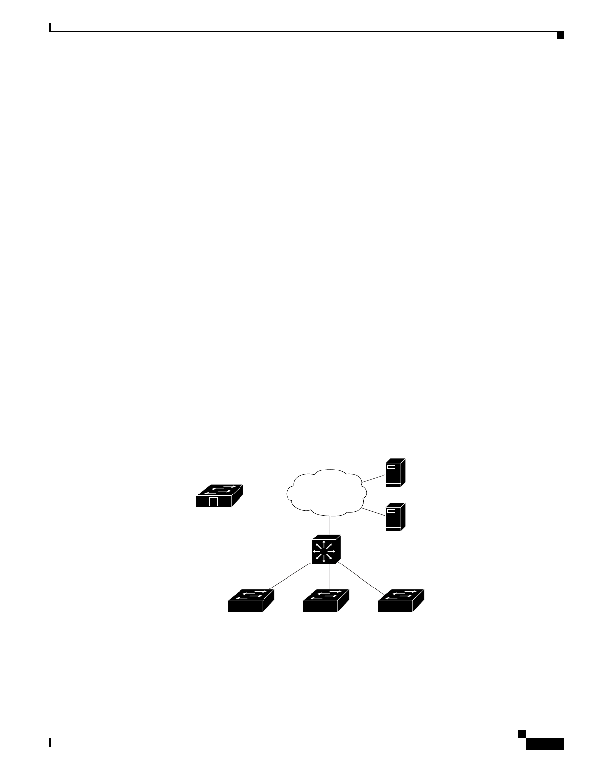
Chapter 4 Configuring Cisco IOS CNS Agents
Understanding Cisco IOS Agents
The CNS event agent feature allows the switch to publish and subscribe to events on the event bus and
works with the Cisco IOS agent. The Cisco IOS agent feature supports the switch by providing these
features:
• Initial Configuration, page 4-5
• Incremental (Partial) Configuration, page 4-6
• Synchronized Configuration, page 4-6
Initial Configuration
When the switch first comes up, it attempts to get an IP address by broadcasting a DHCP request on the
network. Assuming there is no DHCP server on the subnet, the distribution switch acts as a DHCP relay
agent and forwards the request to the DHCP server. Upon receiving the request, the DHCP server assigns
an IP address to the new switch and includes the TFTP server IP address, the path to the bootstrap
configuration file, and the default gateway IP address in a unicast reply to the DHCP relay agent. The
DHCP relay agent forwards the reply to the switch.
Understanding Cisco IOS Agents
The switch automatically configures the assigned IP address on interface VLAN 1 (the default) and
downloads the bootstrap configuration file from the TFTP server. Upon successful download of the
bootstrap configuration file, the switch loads the file in its running configuration.
The Cisco IOS agents initiate communication with the Configuration Engine by using the appropriate
ConfigID and EventID. The Configuration Engine maps the Config ID to a template and downloads the
full configuration file to the switch.
Figure 4-2 shows a sample network configuration for retrieving the initial bootstrap configuration file
by using DHCP-based autoconfiguration.
Figure 4-2 Initial Configuration Overview
TFTP
server
Configuration
Engine
Access layer
V
switches
WAN
DHCP
server
DHCP relay agent
default gatewayDistribution layer
141328
OL-8915-01
Cisco Catalyst Blade Switch 3020 for HP Software Configuration Guide
4-5
Page 88

Configuring Cisco IOS Agents
Incremental (Partial) Configuration
After the network is running, new services can be added by using the Cisco IOS agent. Incremental
(partial) configurations can be sent to the switch. The actual configuration can be sent as an event
payload by way of the event gateway (push operation) or as a signal event that triggers the switch to
initiate a pull operation.
The switch can check the syntax of the configuration before applying it. If the syntax is correct, the
switch applies the incremental configuration and publishes an event that signals success to the
configuration server. If the switch does not apply the incremental configuration, it publishes an event
showing an error status. When the switch has applied the incremental configuration, it can write it to
NVRAM or wait until signaled to do so.
Synchronized Configuration
When the switch receives a configuration, it can defer application of the configuration upon receipt of a
write-signal event. The write-signal event tells the switch not to save the updated configuration into its
NVRAM. The switch uses the updated configuration as its running configuration. This ensures that the
switch configuration is synchronized with other network activities before saving the configuration in
NVRAM for use at the next reboot.
Chapter 4 Configuring Cisco IOS CNS Agents
Configuring Cisco IOS Agents
The Cisco IOS agents embedded in the switch Cisco IOS software allow the switch to be connected and
automatically configured as described in the “Enabling Automated CNS Configuration” section on
page 4-6. If you want to change the configuration or install a custom configuration, see these sections
for instructions:
• Enabling the CNS Event Agent, page 4-8
• Enabling the Cisco IOS CNS Agent, page 4-9
Enabling Automated CNS Configuration
To enable automated CNS configuration of the switch, you must first complete the prerequisites in
Table 4-1 . When you complete them, power on the switch. At the setup prompt, do nothing: The switch
begins the initial configuration as described in the “Initial Configuration” section on page 4-5. When the
full configuration file is loaded on your switch, you need to do nothing else.
4-6
Cisco Catalyst Blade Switch 3020 for HP Software Configuration Guide
OL-8915-01
Page 89

Chapter 4 Configuring Cisco IOS CNS Agents
Table 4-1 Prerequisites for Enabling Automatic Configuration
Device Required Configuration
Access switch Factory default (no configuration file)
Distribution switch
DHCP server
TFTP server
CNS Configuration Engine One or more templates for each type of device, with the ConfigID
Configuring Cisco IOS Agents
• IP helper address
• Enable DHCP relay agent
• IP routing (if used as default gateway)
• IP address assignment
• TFTP server IP address
• Path to bootstrap configuration file on the TFTP server
• Default gateway IP address
• A bootstrap configuration file that includes the CNS
configuration commands that enable the switch to
communicate with the Configuration Engine
• The switch configured to use either the switch MAC address
or the serial number (instead of the default hostname) to
generate the ConfigID and EventID
• The CNS event agent configured to push the configuration file
to the switch
of the device mapped to the template.
Note For more information about running the setup program and creating templates on the Configuration
Engine, see the Cisco Configuration Engine Installation and Setup Guide, 1.5 for Linux at this URL:
http://www.cisco.com/en/US/products/sw/netmgtsw/ps4617/products_installation_and_configuration_
guide_book09186a00803b59db.html
OL-8915-01
Cisco Catalyst Blade Switch 3020 for HP Software Configuration Guide
4-7
Page 90

Configuring Cisco IOS Agents
Enabling the CNS Event Agent
Note You must enable the CNS event agent on the switch before you enable the CNS configuration agent.
Beginning in privileged EXEC mode, follow these steps to enable the CNS event agent on the switch:
Command Purpose
Step 1
Step 2
configure terminal Enter global configuration mode.
cns event {ip-address | hostname} [port-number]
[backup] [init-retry retry-count] [keepalive seconds
retry-count] [source ip-address]
Chapter 4 Configuring Cisco IOS CNS Agents
Enable the event agent, and enter the gateway parameters.
• For {ip-address | hostname}, enter either the
IP address or the hostname of the event gateway.
• (Optional) For port number, enter the port number for
the event gateway. The default port number is 11011.
• (Optional) Enter backup to show that this is the
backup gateway. (If omitted, this is the primary
gateway.)
Step 3
Step 4
Step 5
Step 6
• (Optional) For init-retry retry-count, enter the
number of initial retries before switching to backup.
The default is 3.
• (Optional) For keepalive seconds, enter how often the
switch sends keepalive messages. For retry-count,
enter the number of unanswered keepalive messages
that the switch sends before the connection is
terminated. The default for each is 0.
• (Optional) For source ip-address, enter the source IP
address of this device.
Note Though visible in the command-line help string,
the encrypt and force-fmt1 keywords are not
supported.
end Return to privileged EXEC mode.
show cns event connections Verify information about the event agent.
show running-config Verify your entries.
copy running-config startup-config (Optional) Save your entries in the configuration file.
To disable the CNS event agent, use the no cns event {ip-address | hostname} global configuration
command.
This example shows how to enable the CNS event agent, set the IP address gateway to 10.180.1.27, set
120 seconds as the keepalive interval, and set 10 as the retry count.
Switch(config)# cns event 10.180.1.27 keepalive 120 10
4-8
Cisco Catalyst Blade Switch 3020 for HP Software Configuration Guide
OL-8915-01
Page 91

Chapter 4 Configuring Cisco IOS CNS Agents
Enabling the Cisco IOS CNS Agent
After enabling the CNS event agent, start the Cisco IOS CNS agent on the switch. You can enable the
Cisco IOS agent with these commands:
• The cns config initial global configuration command enables the Cisco IOS agent and initiates an
initial configuration on the switch.
• The cns config partial global configuration command enables the Cisco IOS agent and initiates a
partial configuration on the switch. You can then use the Configuration Engine to remotely send
incremental configurations to the switch.
Enabling an Initial Configuration
Beginning in privileged EXEC mode, follow these steps to enable the CNS configuration agent and
initiate an initial configuration on the switch:
Command Purpose
Step 1
Step 2
configure terminal Enter global configuration mode.
cns config connect-intf interface-prefix
[ping-interval seconds] [retries num]
Configuring Cisco IOS Agents
Enter the connect-interface-config submode, and specify
the interface for connecting to the Configuration Engine.
• Enter the interface-prefix for the connecting interface.
You must specify the interface type but need not
specify the interface number.
Step 3
Step 4
Step 5
Step 6
• (Optional) For ping-interval seconds, enter the
interval between successive ping attempts. The range
is 1 to 30 seconds. The default is 10 seconds.
• (Optional) For retries num, enter the number of ping
retries. The range is 1 to 30. The default is 5.
config-cli
or
line-cli
Enter config-cli to connect to the Configuration Engine
through the interface defined in cns config connect-intf.
Enter line-cli to connect to the Configuration Engine
through modem dialup lines.
Note The config-cli interface configuration command
accepts the special character & that acts as a
placeholder for the interface name. When the
configuration is applied, the & is replaced with the
interface name. For example, to connect through
FastEthernet0/1, the command
route 0.0.0.0 0.0.0.0 &
ip route 0.0.0.0 0.0.0.0 FastEthernet0/1.
config-cli ip
generates the command
exit Return to global configuration mode.
hostname name Enter the hostname for the switch.
ip route network-number Establish a static route to the Configuration Engine whose
IP address is network-number.
OL-8915-01
Cisco Catalyst Blade Switch 3020 for HP Software Configuration Guide
4-9
Page 92

Configuring Cisco IOS Agents
Command Purpose
Step 7
cns id interface num {dns-reverse | ipaddress |
mac-address} [event]
or
cns id {hardware-serial | hostname | string string}
[event]
Step 8
cns config initial {ip-address | hostname}
[port-number] [event] [no-persist] [page page]
[source ip-address] [syntax-check]
Chapter 4 Configuring Cisco IOS CNS Agents
Set the unique EventID or ConfigID used by the
Configuration Engine.
• For interface num, enter the type of interface–for
example, Ethernet, Group-Async, Loopback, or
Virtual-Template. This setting specifies from which
interface the IP or MAC address should be retrieved to
define the unique ID.
• For {dns-reverse | ipaddress | mac-address} enter
dns-reverse to retrieve the hostname and assign it as
the unique ID, enter ipaddress to use the IP address, or
enter mac-address to use the MAC address as the
unique ID.
• (Optional) Enter event to set the ID to be the event-id
value used to identify the switch.
• For {hardware-serial | hostname| string string},
enter hardware-serial to set the switch serial number
as the unique ID, enter hostname (the default) to select
the switch hostname as the unique ID, or enter an
arbitrary text string for string string as the unique ID.
Enable the Cisco IOS agent, and initiate an initial
configuration.
• For {ip-address | hostname}, enter the IP address or
the hostname of the configuration server.
Step 9
• (Optional) For port-number, enter the port number of
the configuration server. The default port number is 80.
• (Optional) Enable event for configuration success,
failure, or warning messages when the configuration is
finished.
• (Optional) Enable no-persist to suppress the
automatic writing to NVRAM of the configuration
pulled as a result of entering the cns config initial
global configuration command. If the no-persist
keyword is not entered, using the cns config initial
command causes the resultant configuration to be
automatically written to NVRAM.
• (Optional) For page page, enter the web page of the
initial configuration. The default is /Config/config/asp.
• (Optional) Enter source ip-address to use for source IP
address.
• (Optional) Enable syntax-check to check the syntax
when this parameter is entered.
Note Though visible in the command-line help string,
the encrypt keyword is not supported.
end Return to privileged EXEC mode.
4-10
Cisco Catalyst Blade Switch 3020 for HP Software Configuration Guide
OL-8915-01
Page 93

Chapter 4 Configuring Cisco IOS CNS Agents
Command Purpose
Step 10
Step 11
show cns config connections Verify information about the configuration agent.
show running-config Verify your entries.
To disable the CNS Cisco IOS agent, use the no cns config initial {ip-address | hostname} global
configuration command.
This example shows how to configure an initial configuration on a remote switch. The switch hostname
is the unique ID. The Cisco Configuration Engine IP address is 172.28.129.22.
Switch(config)# cns config connect-intf serial ping-interval 1 retries 1
Switch(config-cns-conn-if)# config-cli ip address negotiated
Switch(config-cns-conn-if)# config-cli encapsulation ppp
Switch(config-cns-conn-if)# config-cli ip directed-broadcast
Switch(config-cns-conn-if)# config-cli no keepalive
Switch(config-cns-conn-if)# config-cli no shutdown
Switch(config-cns-conn-if)# exit
Switch(config)# hostname RemoteSwitch
RemoteSwitch(config)# ip route 10.1.1.1 255.255.255.255 11.11.11.1
RemoteSwitch(config)# cns id Ethernet 0 ipaddress
RemoteSwitch(config)# cns config initial 10.1.1.1 no-persist
Configuring Cisco IOS Agents
Enabling a Partial Configuration
Beginning in privileged EXEC mode, follow these steps to enable the Cisco IOS agent and to initiate a
partial configuration on the switch:
Command Purpose
Step 1
Step 2
Step 3
Step 4
Step 5
Step 6
configure terminal Enter global configuration mode.
cns config partial {ip-address | hostname}
[port-number] [source ip-address]
end Return to privileged EXEC mode.
show cns config stats
or
show cns config outstanding
show running-config Verify your entries.
copy running-config startup-config (Optional) Save your entries in the configuration file.
Enable the configuration agent, and initiate a partial
configuration.
• For {ip-address | hostname}, enter the IP address or
the hostname of the configuration server.
• (Optional) For port-number, enter the port number of
the configuration server. The default port number is 80.
• (Optional) Enter source ip-address to use for the
source IP address.
Note Though visible in the command-line help string,
the encrypt keyword is not supported.
Verify information about the configuration agent.
OL-8915-01
To disable the Cisco IOS agent, use the no cns config partial {ip-address | hostname} global
configuration command. To cancel a partial configuration, use the cns config cancel privileged EXEC
command.
Cisco Catalyst Blade Switch 3020 for HP Software Configuration Guide
4-11
Page 94

Displaying CNS Configuration
Displaying CNS Configuration
You can use the privileged EXEC commands in Tabl e 4 -2 to display CNS configuration information.
Table 4-2 Displaying CNS Configuration
Command Purpose
show cns config connections Displays the status of the CNS Cisco IOS agent connections.
show cns config outstanding Displays information about incremental (partial) CNS
configurations that have started but are not yet completed.
show cns config stats Displays statistics about the Cisco IOS agent.
show cns event connections Displays the status of the CNS event agent connections.
show cns event stats Displays statistics about the CNS event agent.
show cns event subject Displays a list of event agent subjects that are subscribed to by
applications.
Chapter 4 Configuring Cisco IOS CNS Agents
4-12
Cisco Catalyst Blade Switch 3020 for HP Software Configuration Guide
OL-8915-01
Page 95

Administering the Switch
This chapter describes how to perform one-time operations to administer the switch.
This chapter consists of these sections:
• Managing the System Time and Date, page 5-1
• Configuring a System Name and Prompt, page 5-14
• Creating a Banner, page 5-17
• Managing the MAC Address Table, page 5-19
• Managing the ARP Table, page 5-26
Managing the System Time and Date
You can manage the system time and date on your switch using automatic configuration, such as the
Network Time Protocol (NTP), or manual configuration methods.
CHAPTER
5
Note For complete syntax and usage information for the commands used in this section, see the Cisco IOS
Configuration Fundamentals Command Reference, Release 12.2.
These sections contain this configuration information:
• Understanding the System Clock, page 5-1
• Understanding Network Time Protocol, page 5-2
• Configuring NTP, page 5-3
• Configuring Time and Date Manually, page 5-11
Understanding the System Clock
The heart of the time service is the system clock. This clock runs from the moment the system starts up
and keeps track of the date and time.
The system clock can then be set from these sources:
• NTP
• Manual configuration
OL-8915-01
Cisco Catalyst Blade Switch 3020 for HP Software Configuration Guide
5-1
Page 96

Managing the System Time and Date
The system clock can provide time to these services:
• User show commands
• Logging and debugging messages
The system clock keeps track of time internally based on Universal Time Coordinated (UTC), also
known as Greenwich Mean Time (GMT). You can configure information about the local time zone and
summer time (daylight saving time) so that the time appears correctly for the local time zone.
The system clock keeps track of whether the time is authoritative or not (that is, whether it has been set
by a time source considered to be authoritative). If it is not authoritative, the time is available only for
display purposes and is not redistributed. For configuration information, see the “Configuring Time and
Date Manually” section on page 5-11.
Understanding Network Time Protocol
The NTP is designed to time-synchronize a network of devices. NTP runs over User Datagram Protocol
(UDP), which runs over IP. NTP is documented in RFC 1305.
An NTP network usually gets its time from an authoritative time source, such as a radio clock or an
atomic clock attached to a time server. NTP then distributes this time across the network. NTP is
extremely efficient; no more than one packet per minute is necessary to synchronize two devices to
within a millisecond of one another.
Chapter 5 Administering the Switch
NTP uses the concept of a stratum to describe how many NTP hops away a device is from an
authoritative time source. A stratum 1 time server has a radio or atomic clock directly attached, a
stratum 2 time server receives its time through NTP from a stratum 1 time server, and so on. A device
running NTP automatically chooses as its time source the device with the lowest stratum number with
which it communicates through NTP. This strategy effectively builds a self-organizing tree of NTP
speakers.
NTP avoids synchronizing to a device whose time might not be accurate by never synchronizing to a
device that is not synchronized. NTP also compares the time reported by several devices and does not
synchronize to a device whose time is significantly different than the others, even if its stratum is lower.
The communications between devices running NTP (known as associations) are usually statically
configured; each device is given the IP address of all devices with which it should form associations.
Accurate timekeeping is possible by exchanging NTP messages between each pair of devices with an
association. However, in a LAN environment, NTP can be configured to use IP broadcast messages
instead. This alternative reduces configuration complexity because each device can simply be configured
to send or receive broadcast messages. However, in that case, information flow is one-way only.
The time kept on a device is a critical resource; you should use the security features of NTP to avoid the
accidental or malicious setting of an incorrect time. Two mechanisms are available: an access list-based
restriction scheme and an encrypted authentication mechanism.
Cisco’s implementation of NTP does not support stratum 1 service; it is not possible to connect to a radio
or atomic clock. We recommend that the time service for your network be derived from the public NTP
servers available on the IP Internet.
5-2
Cisco Catalyst Blade Switch 3020 for HP Software Configuration Guide
OL-8915-01
Page 97

Chapter 5 Administering the Switch
Figure 5-1 shows a typical network example using NTP. Switch A is the NTP master, with Switches B,
C, and D configured in NTP server mode, in server association with Switch A. Switch E is configured
as an NTP peer to the upstream and downstream switches, Switch B and Switch F.
Figure 5-1 Typical NTP Network Configuration
Local
workgroup
servers
Managing the System Time and Date
Switch A
Switch B
Switch E
Workstations
Switch F
Workstations
Switch C Switch D
101349
If the network is isolated from the Internet, Cisco’s implementation of NTP allows a device to act as if
it is synchronized through NTP, when in fact it has learned the time by using other means. Other devices
then synchronize to that device through NTP.
When multiple sources of time are available, NTP is always considered to be more authoritative. NTP
time overrides the time set by any other method.
Several manufacturers include NTP software for their host systems, and a publicly available version for
systems running UNIX and its various derivatives is also available. This software allows host systems to
be time-synchronized as well.
Configuring NTP
The switch does not have a hardware-supported clock and cannot function as an NTP master clock to
which peers synchronize themselves when an external NTP source is not available. The switch also has
no hardware support for a calendar. As a result, the ntp update-calendar and the ntp master global
configuration commands are not available.
OL-8915-01
Cisco Catalyst Blade Switch 3020 for HP Software Configuration Guide
5-3
Page 98

Managing the System Time and Date
These sections contain this configuration information:
• Default NTP Configuration, page 5-4
• Configuring NTP Authentication, page 5-4
• Configuring NTP Associations, page 5-5
• Configuring NTP Broadcast Service, page 5-6
• Configuring NTP Access Restrictions, page 5-8
• Configuring the Source IP Address for NTP Packets, page 5-10
• Displaying the NTP Configuration, page 5-11
Default NTP Configuration
Table 5-1 shows the default NTP configuration.
Table 5-1 Default NTP Configuration
Feature Default Setting
NTP authentication Disabled. No authentication key is specified.
NTP peer or server associations None configured.
NTP broadcast service Disabled; no interface sends or receives NTP broadcast packets.
NTP access restrictions No access control is specified.
NTP packet source IP address The source address is set by the outgoing interface.
Chapter 5 Administering the Switch
NTP is enabled on all interfaces by default. All interfaces receive NTP packets.
Configuring NTP Authentication
This procedure must be coordinated with the administrator of the NTP server; the information you
configure in this procedure must be matched by the servers used by the switch to synchronize its time to
the NTP server.
Beginning in privileged EXEC mode, follow these steps to authenticate the associations (communications
between devices running NTP that provide for accurate timekeeping) with other devices for security
purposes:
Command Purpose
Step 1
Step 2
configure terminal Enter global configuration mode.
ntp authenticate Enable the NTP authentication feature, which is disabled by
default.
5-4
Cisco Catalyst Blade Switch 3020 for HP Software Configuration Guide
OL-8915-01
Page 99

Chapter 5 Administering the Switch
Command Purpose
Step 3
Step 4
ntp authentication-key number md5 value Define the authentication keys. By default, none are defined.
ntp trusted-key key-number Specify one or more key numbers (defined in Step 3) that a peer
Managing the System Time and Date
• For number, specify a key number. The range is 1 to
4294967295.
• md5 specifies that message authentication support is provided
by using the message digest algorithm 5 (MD5).
• For value, enter an arbitrary string of up to eight characters for
the key.
The switch does not synchronize to a device unless both have one
of these authentication keys, and the key number is specified by the
ntp trusted-key key-number command.
NTP device must provide in its NTP packets for this switch to
synchronize to it.
By default, no trusted keys are defined.
For key-number, specify the key defined in Step 3.
Step 5
Step 6
Step 7
end Return to privileged EXEC mode.
show running-config Verify your entries.
copy running-config startup-config (Optional) Save your entries in the configuration file.
To disable NTP authentication, use the no ntp authenticate global configuration command. To remove
an authentication key, use the no ntp authentication-key number global configuration command. To
disable authentication of the identity of a device, use the no ntp trusted-key key-number global
configuration command.
This example shows how to configure the switch to synchronize only to devices providing authentication
key 42 in the device’s NTP packets:
Switch(config)# ntp authenticate
Switch(config)# ntp authentication-key 42 md5 aNiceKey
Switch(config)# ntp trusted-key 42
Configuring NTP Associations
An NTP association can be a peer association (this switch can either synchronize to the other device or
allow the other device to synchronize to it), or it can be a server association (meaning that only this
switch synchronizes to the other device, and not the other way around).
This command provides protection against accidentally
synchronizing the switch to a device that is not trusted.
OL-8915-01
Cisco Catalyst Blade Switch 3020 for HP Software Configuration Guide
5-5
Page 100

Managing the System Time and Date
Beginning in privileged EXEC mode, follow these steps to form an NTP association with another device:
Command Purpose
Step 1
Step 2
configure terminal Enter global configuration mode.
ntp peer ip-address [version number]
[key keyid] [source interface] [prefer]
Chapter 5 Administering the Switch
Configure the switch system clock to synchronize a peer or to be
synchronized by a peer (peer association).
Step 3
Step 4
Step 5
or
ntp server ip-address [version number]
[key keyid] [source interface] [prefer]
or
Configure the switch system clock to be synchronized by a time server
(server association).
No peer or server associations are defined by default.
• For ip-address in a peer association, specify either the IP address of
the peer providing, or being provided, the clock synchronization. For
a server association, specify the IP address of the time server
providing the clock synchronization.
• (Optional) For number, specify the NTP version number. The range is
1 to 3. By default, Version 3 is selected.
• (Optional) For keyid, enter the authentication key defined with the
ntp authentication-key global configuration command.
• (Optional) For interface, specify the interface from which to pick the
IP source address. By default, the source IP address is taken from the
outgoing interface.
• (Optional) Enter the prefer keyword to make this peer or server the
preferred one that provides synchronization. This keyword reduces
switching back and forth between peers and servers.
end Return to privileged EXEC mode.
show running-config Verify your entries.
copy running-config startup-config (Optional) Save your entries in the configuration file.
You need to configure only one end of an association; the other device can automatically establish the
association. If you are using the default NTP version (Version 3) and NTP synchronization does not
occur, try using NTP Version 2. Many NTP servers on the Internet run Version 2.
To remove a peer or server association, use the no ntp peer ip-address or the no ntp server ip-address
global configuration command.
This example shows how to configure the switch to synchronize its system clock with the clock of the
peer at IP address 172.16.22.44 using NTP Version 2:
Switch(config)# ntp server 172.16.22.44 version 2
Configuring NTP Broadcast Service
The communications between devices running NTP (known as associations) are usually statically
configured; each device is given the IP addresses of all devices with which it should form associations.
Accurate timekeeping is possible by exchanging NTP messages between each pair of devices with an
association. However, in a LAN environment, NTP can be configured to use IP broadcast messages
instead. This alternative reduces configuration complexity because each device can simply be configured
to send or receive broadcast messages. However, the information flow is one-way only.
Cisco Catalyst Blade Switch 3020 for HP Software Configuration Guide
5-6
OL-8915-01
 Loading...