

Page 1
INSTRUCTION HANDBOOK
Please read the instruction handbook before using the printer . Keep it close to the printer
for easy reference.
Page 2
Please read the instruction handbook before using the printer. Keep it close to the printer
for easy reference.
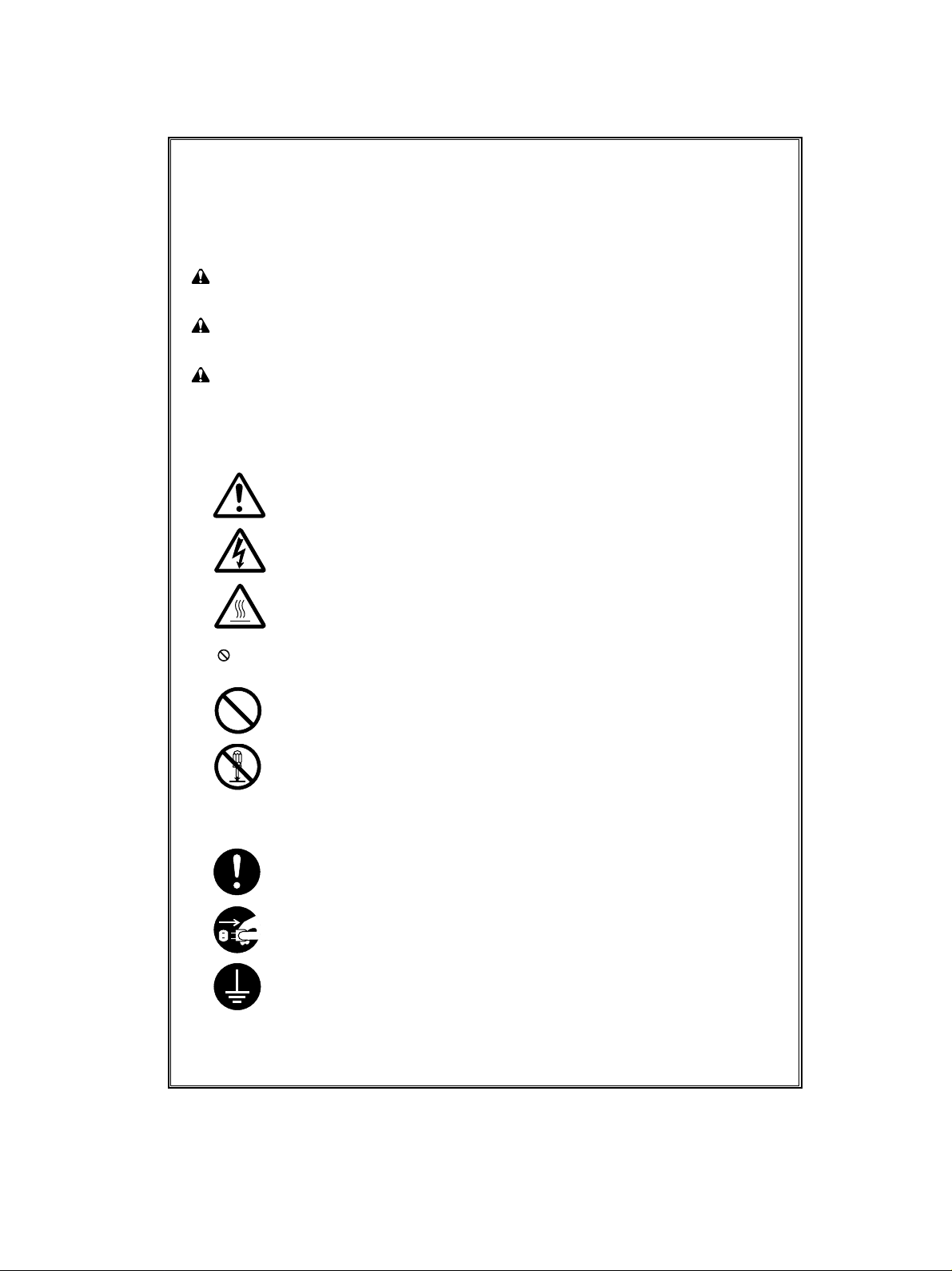
The sections of this handbook and parts of the printer marked with symbols are safety warnings meant to
protect the user, other individuals and surrounding objects, and ensure correct and safe usage of the
printer. The symbols and their meanings are indicated below.
DANGER: Indicates that serious injury or even death will very possibly result from insufficient attention
to or incorrect compliance with the related points.
WARNING: Indicates that serious injury or even death may result from insufficient attention to or
incorrect compliance with the related points.
CAUTION: Indicates that personal injury or mechanical damage may result from insufficient attention
to or incorrect compliance with the related points.
Symbols
The m symbol indicates that the related section includes safety warnings. Specific points of attention are
indicated inside the symbol.
......... [General warning]
........ [Warning of danger of electrical shock]
........ [Warning of high temperature]
The symbol indicates that the related section includes information on prohibited actions. Specifics of
the prohibited action are indicated inside the symbol.
.......... [Warning of prohibited action]
.......... [Disassembly prohibited]
The ● symbol indicates that the related section includes information on actions which must be performed.
Specifics of the required action are indicated inside the symbol.
.......... [Alert of required action]
.......... [Remove the power plug from the outlet]
.......... [Always connect the printer to an outlet with a ground connection]
Please contact your service representative to order a replacement if the safety warnings in the handbook
are illegible or if the handbook itself is missing. (fee required)
i
Page 3

Thank you for purchasing the Ci 1100 Color Laser Printer.
Notice
NO LIABILITY IS ASSUMED FOR ANY DAMAGE CAUSED BY IMPROPER INSTALLATION.
The information in this Instruction Handbook is subject to change without notification. Additional pages may be
inserted in future editions. The user is asked to excuse any technical inaccuracies or typographical errors in the
present edition.
SOFTWARE USED WITH THIS PRINTER MUST SUPPORT THE PRINTER’S NATIVE MODE OR ONE OF ITS
EMULATION MODES. The printer is factory set to emulate the PCL 5C. The emulation mode can be changed by
following the procedures described in
No responsibility is assumed if accidents occur while the user is following the instructions in this Instruction
Handbook. No responsibility is assumed for defects in the printer’s firmware (contents of its read-only memory).
This Instruction Handbook, any copyrightable subject matter sold or provided with or in connection with the sale of
the printer, are protected by copyright. All rights are reserved. Copying or other reproduction of all or part of this
Instruction Handbook, any copyrightable subject matter without the prior written consent of the copyright holder is
prohibited. Any copies made of all or part of this Instruction Handbook, any copyrightable subject must contain the
same copyright notice as the material from which the copying is done.
Regarding Tradenames
KPDL is a trademark of Kyocera Corporation. HP Color LaserJet 5 is a product of Hewlett-Packard Company.
Hewlett-Packard, PCL, and PJL are registered trademarks of Hewlett-Packard Company. Centronics is a trade
name of Centronics Data Computer Corp. Microsoft and Windows are registered trademarks of Microsoft
Corporation in the United States and/or other countries. Pentium is a registered trademark of Intel Corporation.
PostScript is a registered trademark of Adobe Systems Incorporated. Apple and Macintosh are trademarks of Apple
Computer, Inc. registered in the U.S. and other countries. Adobe and Acrobat are trademarks of Adobe Systems
Incorporated which may be registered in certain jurisdictions. All other trademarks are the property of their
respective owners.
Using the Printer
.
Typeface Trademark Acknowledgement
All resident fonts in this printer are licensed from Bitstream Inc., Cambridge, Massachusetts, U.S.A.
Dutch801, Swiss742, Incised901, ZapfCalligraphic801, ZapfHumanist601, OriginalGaramond, and Chianti are
trademarks of Bitstream Inc.
Century Schoolbook, Stymie, and Cooper-Black are trademarks of Kingsley-ATF Type Corporation.
ITC AvantGarde, ITC Benguiat, ITC Bookman, ITC Souvenir, ITC ZapfChancery, and ITC ZapfDingbats are
registered trademarks of International Type-face Corporation.
Revue is a trademark of Esselte Pendaflex Corporation in the U.S., Letraset Canada Ltd. in Canada, and Esselte
Letraset Ltd. elsewhere.
Bitstream Sublicense Agreement
FONTWARE/TrueDoc developed by BITSTREAM INC. is provided as part of this Printer by manufacture under
license. Manufacture, as a Licensee of BITSTREAM, grants you, the Sublicensee, non-exclusive right to use
FONTWARE/TrueDoc installed in this Printer, if you agree to and at all times comply with the following items:
1. Ownership
As the Sublicensee, you own the Printer in which FONTWARE/TrueDoc is originally installed, but BITSTREAM
retains title to and ownership in the software program of FONTWARE/TrueDoc. The Sublicense is not a sale of the
original software program of FONTWARE/TrueDoc or any portion or copy of it.
ii
Page 4

2. Copy Restrictions
FONTWARE/TrueDoc is copyrighted. Unauthorized copying of FONTWARE/TrueDoc even if modified, merged, or
included with other software, is expressly forbidden. You may be held legally responsible for any copyright infringement.
3. Unauthorized Use
FONTWARE/TrueDoc may not be removed, disclosed and transferred to any third party for any length of time
without the prior written consent of manufacture or BITSTREAM. Also, you may not modify, adapt, translate,
reverse engineer, decompile, or create derivative works based on FONTWARE/TrueDoc.
4. Term
This agreement should remain in full force and effect forever thereby allowing the Sublicensee to use the
FONTWARE/TrueDoc forever unless the Sublicensee violates the terms of paragraphs 2. or 3. above. In the event of
such violation, this agreement will terminate automatically without notice from manufacture. Upon termination,
you should destroy FONTWARE/TrueDoc and all copies of them, in part and in whole, including modified copies, if
any.
Important note on the interface connectors
Be sure to turn off printer power before connecting or disconnecting an interface cable* to the printer. For protection
against static discharge which may be applied to the printer’s internal electronics through the interface connector(s),
keep any interface connector which is not in use capped using the protective cap supplied.
* A shielded interface cable must be used.
Ozone concentration
The printer generates ozone gas (O3) which may concentrate in the place of installation and cause an unpleasant
smell. To minimize concentration of ozone gas to less than 0.1 ppm, we recommend you not to install the printer in a
confined area where ventilation is blocked.
iii
Page 5

FCC statement
This device complies with Part 15 of the FCC Rules. Operation is subject to the following two conditions: (1) This
device may not cause harmful interference, and (2) this device must accept any interference received, including
interference that may cause undesired operation.
This equipment has been tested and found to comply with the limits for a Class B digital device, pursuant to Part 15
of the FCC Rules. These limits are designed to provide reasonable protection against harmful interference in a
residential installation. This equipment generates, uses, and can radiate radio frequency energy and, if not installed
and used in accordance with the instructions, may cause harmful interference to radio communications. However,
there is no guarantee that interference will not occur in a particular installation. If this equipment does cause
harmful interference to radio or television reception, which can be determined by turning the equipment off and on,
the user is encouraged to try to correct the interference by one or more of the following measures:
Reorient or relocate the receiving antenna.
Increase the separation between the equipment and receiver.
Connect the equipment into an outlet on a circuit different from that to which the receiver is connected.
Consult the dealer or an experienced radio/TV technician for help.
Changes or modifications not expressly approved by the manufacturer for compliance could void the user’s authority
to operate the equipment.
Shielded circular cable should be used for interfacing with the computer.
Caution to user
Any modification without prior permission may cause harmful interference.
If any modification/change is introduced to this equipment without prior permission, we as the manufacturer cannot
guarantee compliance with FCC rules.
To use equipment which does not comply with FCC rules is prohibited.
The printer may be optionally installed with the following options:
Conforming to the Class B limits
Lower Feeding Unit for Ci1100
AD-32 Duplex Unit
Hard Disk Drive Option for Ci1100
Barcord Reader
Interface connectors
Important note on the interface connectors
Be sure to turn off printer power before connecting or disconnecting an interface cable* to the printer. For protection
against static discharge which may be applied to the printer’s internal electronics through the interface connector(s),
keep any interface connector which is not in use capped using the protective cap supplied.
* Use shielded interface cable.
iv
Page 6
Safety information
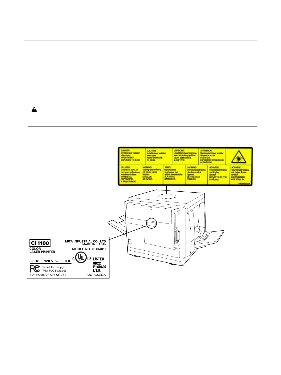
Laser safety
This printer is certified as a Class 1 laser product under the U.S. Department of Health and Human Services
(DHHS) Radiation Performance Standard according to Radiation Control for Health and Safety Act of 1968. This
means that the printer does not produce hazardous laser radiation. Since radiation emitted inside the printer is
completely confined within protective housings and external covers, the laser beam cannot escape from the printer
during any phase of user operation.
Laser notice
This printer is certified in the U.S. to conform to the requirements of DHHS 21 CFR Subchapter for Class I (1) laser
products, and elsewhere is certified as a Class I laser product conforming to the requirements of IEC 825.
Caution:
Laser radiation when open. DO NOT STARE INTO BEAM OR VIEW DIRECTLY WITH OPTICAL
INSTRUMENTS.
* Use of controls or adjustments or performance of procedures other than those specified herein may
result in hazardous radiation exposure.
CDRH regulations
The Center of Devices and Radiological Health (CDRH) of the U.S. Food and Drug Administration implemented
regulations for laser products on August 2, 1976. These regulations apply to laser products manufactured after
August 1, 1976. Compliance is mandatory for products marketed in the United States. A label indicating compliance
with the CDRH regulations must be attached to laser products marketed in the United States.
v
Page 7

Disclaimer
We shall have no liability or responsibility to customers or any other person or entity with respect to any liability,
loss or damage caused or alleged to be caused directly or indirectly by equipment sold or furnished by us, including
but not limited to, any interruption of service, loss of business or anticipatory profits, or consequential damages
resulting from the use or operation of the equipment or software.
ENERGY STAR
As an ENERGY STAR Partner, Mita (Mita Copystar America, Inc.) has determined that this product meets the
ENERGY STAR guidelines for energy efficiency.
* ENERGY STAR is a U.S. registered mark.
vi
Page 8

Chapter 1
For Y our
Safety
Chapter 2
Before Y ou
Start
Contents
CAUTION LABELS ..................................................................... 1
INSTALLA TION PRECATIONS................................................... 2
PRECATIONS FOR USE ............................................................ 3
System Requirements .................................................................... 5
PC ......................................................................................................................5
Interface .............................................................................................................5
Features ........................................................................................... 6
Unpacking........................................................................................ 6
Part Names ...................................................................................... 7
Control Panel Overview.................................................................. 8
Chapter 3
Setup
Setting Up the Printer ................................................................... 12
Preparing the Imaging Unit..............................................................................12
Setting Up the Output Tray...............................................................................13
Installing the Toner Developers........................................................................14
Loading Media............................................................................... 16
Loading Paper or Transparencies in the Media Cassette ...............................16
Loading Media in the Multi-purpose Tray ........................................................19
Connecting the Printer to a Computer........................................ 23
Using a Parallel Interface Cable ......................................................................24
Connecting the Serial Interface .......................................................................25
Installing the Hard Disk Option ........................................................................25
Power On ....................................................................................... 25
Printing a Status Page From the Printer Control Panel............. 26
Installing the Driver Software ...................................................... 27
Setting the Color Density ............................................................. 30
vii
Page 9

Contents
Chapter 4
Using the
Printer
Chapter 5
Care and
Maintenance
Mode Selection.............................................................................. 34
Navigating through the menus.........................................................................37
Outline for Menus.............................................................................................38
Other menus (Others)......................................................................................47
RAM DISK........................................................................................................51
Virtual Mail Box (VMB).....................................................................................52
Memory Cards .................................................................................................57
Setting the Sleep Timer ...................................................................................62
Resource Protection ........................................................................................62
Cleaning......................................................................................... 64
User Replaceable Components ................................................... 69
Clearing a Jam .............................................................................. 71
Troubleshooting............................................................................ 85
Error Messages ............................................................................. 93
Printer Panel Message ....................................................................................93
Repacking.................................................................................... 101
Appendix
Specifications.............................................................................. 110
Printer ............................................................................................................110
Media ............................................................................................................. 111
Margins and Print Area .................................................................................. 112
Software.........................................................................................................115
Bi-directional Parallel Interface......................................................................116
viii
Page 10
For Your Safety
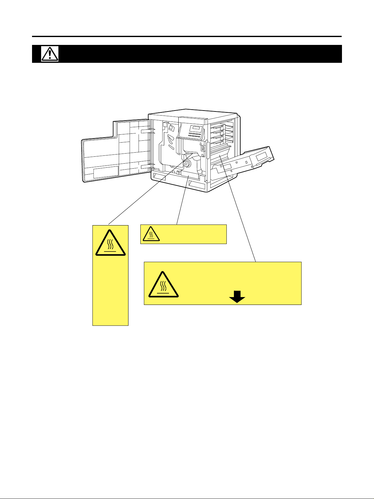
CAUTION:
HOT SURFACE BELOW
ATTENTION:
SURFACE CHAUDE CI-DESSOUS
VORSICHT:
HEIßE OBERFLÄCHE DARUNTER
ATENCION:
SUPERFICIE CALIENTE ABAJO
CAUTION LABELS
Caution labels have been attached to the printer at the following locations for safety purposes. BE SUFFICIENTLY
CAREFUL to avoid fire or electric shock when removing a paper jam or when replacing toner.
CAUTION:
HOT SURFACE
INSIDE
ATTENTION:
SURFACE
CHAUDE
CI-INTERIEUR
VORSICHT:
HEISSE FLÄCHE
INTERN
ATENCION:
SUPERFICIE
CALIENTE
EN EL INTERNO
CAUTION:
HOT SURFACE INSIDE
NOTE: DO NOT remove these labels.
1
Page 11
For Your Safety
INSTALLATION PRECAUTIONS
■ Environment
CAUTION
• Avoid placing the printer on or in locations which are unstable or not level. Such locations may cause the
printer to fall down or fall over. This type of situation presents a danger of personal injury or damage to
the printer. ................................................................................................................................................................
• Avoid locations with humidity or dust and dirt. If dust or dirt become attached to the power plug, clean the
plug to avoid the danger of fire or electrical shock. ...............................................................................................
• Avoid locations near radiators, heaters, or other heat sources, or locations near flammable items, to avoid
the danger of fire. .....................................................................................................................................................
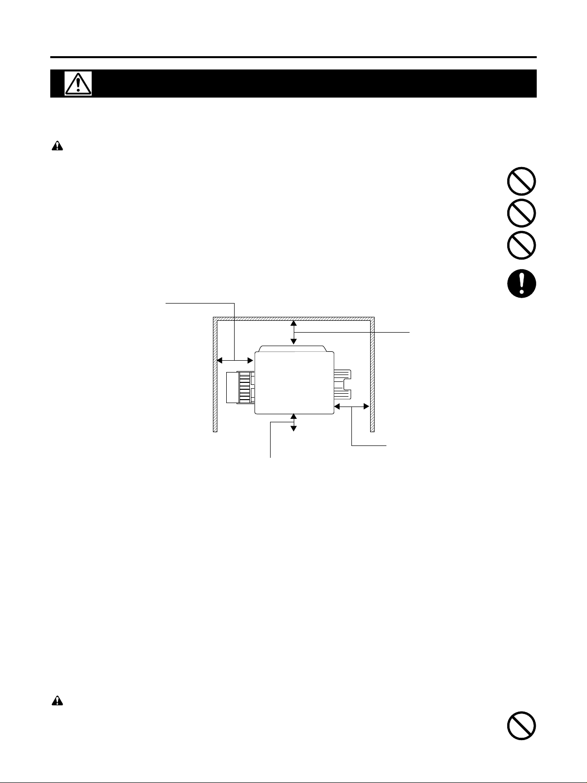
• To keep the printer cool and facilitate changing of parts and maintenance, allow access space as shown
below.
Leave adequate space, especially around the rear cover, to allow air to be properly ventilated out of the
pr i nt e r. .......................................................................................................................................................................
45 cm (17.7”)
Multi-Purpose Tray
Opening Space
Rear
35 cm (13.8”)
Controller Board
Opening Space
Left
60 cm (23.6”)
Other precautions
• To avoid machine malfunction, do not use the equipment under the following conditions:
• Direct exposure to sunlight
• Extremely high or low temperature [temperature range: 10˚C to 32.5˚C (50˚F to 90.5˚F)]
• Extremely high or low humidity (humidity range: 20% to 80% RH)
• Condensation due to rapid change of temperature
• Areas of poor ventilation
• Areas of high dust or chemical fume concentration (solvent etc.)
• Make sure that the printer is installed in a well ventilated room so as not to increase density of ozone in the air.
Since ozone is heavier than air, it is recommended that air at floor level be ventilated.
• The printer weighs approximately 51 kg (112 lbs.). It must be handled by two people.
Front cover opening space
Right
50 cm (19.7”)
Media tray Opening
Space
■ Power supply/Grounding the printer
WARNING
• DO NOT use a power supply with a voltage other than that specified. Avoid multiple connections in the
same outlet. These types of situations present a danger of fire or electrical shock. ...........................................
2
Page 12
For Y our Safety
• Plug the power cord securely into the outlet. If metallic objects come in contact with the prongs on the
plug, it may cause a fire or electric shock. ..............................................................................................................
• Always connect the printer to an outlet with a ground connection to avoid the danger of fire or electrical
shock in case of an electric short. If an earth connection is not possible, contact your service representative.
Other precautions
• The power source voltage of this unit is listed on the nameplate. Only plug the unit into an outlet with the proper
voltage.
• Always use a shielded interface cable. Use of an unshielded cable can result in radio interference with data.
■ Static Electricity Damage
• To prevent static electricity damage to any of the following components, touch a grounded metal surface, such as
the printer’s bare metal frame prior to touching the component.
• The interface connectors: Parallel and optional network card
• Electrical components, connectors inside the printer and any components on the optional boards (RAM
expansion board, network interface board, etc.)
• The connector pins on the optional paper feeder for the printer
■ Handling of plastic bags
WARNING
• Keep the plastic bags that are used with the printer away from children. The plastic may cling to their
nose and mouth causing suffocation. ......................................................................................................................
PRECAUTIONS FOR USE
■ Cautions when using the printer
WARNING
• DO NOT place metallic objects or containers with water (flower vases, flower pots, cups, etc.) on or near
the printer. This type of situation presents a danger of fire or electrical shock should they fall inside. ..........
• DO NOT remove any of the covers from the printer as there is a danger of electrical shock from high
voltage parts inside the printer. ..............................................................................................................................
• DO NOT damage, break or attempt to repair the power cord. DO NOT place heavy objects on the cord, pull
it, bend it unnecessarily or cause any other type of damage.
These types of situations present a danger of fire or electrical shock. .................................................................
• NEVER attempt to repair or disassemble the printer or its parts as there is a danger of fire, electrical
shock or damage to the laser. If the laser beam escapes, there is a danger of it causing blindness. ................
• If the printer becomes excessively hot, smoke appears from the printer, there is an odd smell, or any other
abnormal situation occurs, there is a danger of fire or electrical shock. Turn the power switch OFF (O)
immediately, remove the power plug from the outlet and contact your service representative. .......................
• If anything harmful (paper clips, water, other fluids, etc.) falls into the printer, turn the power switch OFF
(O) immediately. Next, remove the power plug from the outlet to avoid the danger of fire or electrical
shock. Then contact your service representative. ..................................................................................................
3
Page 13
For Your Safety
• When adding memory, ALWAYS remove the power plug from the outlet. If this operation is performed
with the power still attached, there is a danger of electrical shock. ....................................................................
• DO NOT remove or connect the power plug with wet hands, as there is a danger of electrical shock. ............
• ALWAYS contact your service representative for maintenance or repair of internal parts. .............................
CAUTION
• DO NOT pull the power cord when removing it from the outlet. If the power cord is pulled, the wires may
become broken and there is a danger of fire or electrical shock. (ALWAYS grasp the power plug when
removing the power cord from the outlet.) .............................................................................................................
• ALWAYS remove the power plug from the outlet when moving the printer. If the power cord is damaged,
there is a danger of fire or electrical shock. ...........................................................................................................
• If the printer will not be used for a short period of time (overnight, etc.), turn the power switch OFF (O).
If it will not be used for an extended period of time (vacations, etc.), remove the power plug from the outlet
for safety purposes during the time the printer is not in use. ..............................................................................
• ALWAYS hold the designated parts only when lifting or moving the printer. ...................................................
• For safety purposes, ALWAYS remove the power plug from the outlet when performing cleaning
operations. .................................................................................................................................................................
• If dust accumulates within the printer, there is a danger of fire or other trouble. It is therefore
recommended that you consult with your service representative in regard to cleaning of internal parts.
This is particularly effective if accomplished prior to seasons of high humidity. Consult with your service
representative in regard to the cost of cleaning the internal parts of the printer. .............................................
Other precautions
• Too much media which exceeds the limit mark on the guide of the tray.
• Front/right/left covers opened while the printer is operating. It may cause a media jam.
• We strongly recommend to use only the original toner developer. Use of our toner developer assures the intended
long term reliability of the printer.
■ Cautions when handling consumables
CAUTION
• Avoid inhalation, ingestion, skin or eye contact. If ingestion occurs, dilute stomach contents thoroughly
with water and seek medical treatment. If skin contact occurs, wash with soap and water. If contact with
eyes occurs, flush thoroughly with water and seek medical treatment. ..............................................................
• Prolonged inhalation of excessive dusts may cause lung damage. Use of this product, as intended, does not
result in inhalation of excessive dusts. ...................................................................................................................
• Do not incinerate toner and toner containers. Dangerous sparks may cause burn. ...........................................
• Keep away from children. ........................................................................................................................................
■ Waste Disposal Method
Waste material may be dumped or incinerated under conditions which meet the applicable environmental
regulations.
4
Page 14

System Requirements
PC
To operate the Ci 1100 effectively, refer to the following:
CPU: More than Pentium
Operating System: Windows 95
RAM: 16 MB or more (More than 32 MB is recommended.)
Free disk space: 100 MB or more
Virtual memory: 16 MB or more (More than 32 MB is recommended.)
Display: Video card that can display more than 256 colors.
*1
Microsoft® Windows® 95 operating system (hereafter Windows 95)
*2
Microsoft® Windows® 98 operating system (hereafter Windows 98)
Before Y ou Start
(133 MHz or faster CPU is recommended.)
(32,000 color recommended.)
*1
/ Windows 98
*2
Interface
■ Parallel interface requirement
Based on the IEEE1284 standard (An ECP compatible paral-
Interface
■ Network interface requirements
Manufacturer Model Applicable country
Ethernet DPI
See your nearest dealer of the manufacturer for availability.
lel port is recommended for Windows 95. To turn on the ECP
mode, use the computer’s BIOS setup. Refer to the computer’s manual for details.)
EcoLAN 2000E
EcoLAN 3000E
Available in USA and Japan
5
Page 15
Before Y ou Start
Features
The Ci 1100 Color Laser Printer provides fast, high-quality color printing on plain paper,
plus the ease of operation and high performance you expect from a laser printer.
Some of its features include:
■ High quality
Resolution
Maximum 1200 dpi*
(*KPDL emulation only)
■ High speed
For printing of multiple copies on various sizes of paper
Full-color mode: Maximum 4 ppm (pages per minute)
Monochrome mode: Maximum 16 ppm
■ Easy operation
Printer driver
Easily prints full-color documents.
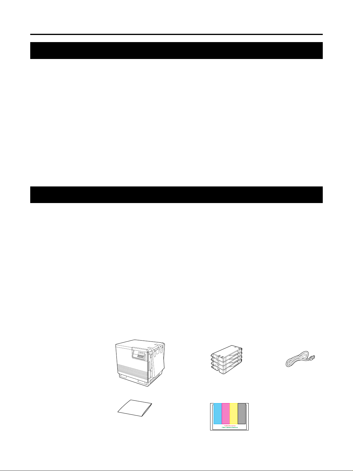
Unpacking
Make sure that all of the items shown below were provided and have not been damaged.
Report damage or shortages to the reseller from which the unit was purchased.
Note:
Save the original carton and packing materials for future shipping and transporting of
the unit. They have been specifically designed to protect the equipment during
shipment.
1. Printer (Color imaging unit, Fuser kit, Paper cassette and Output tray are
included.)
2. Toner developers (black, cyan, magenta, and yellow)
3. Power cord
4. Drivers
5. Color Calibration Reference card
123
4
5
6
Page 16
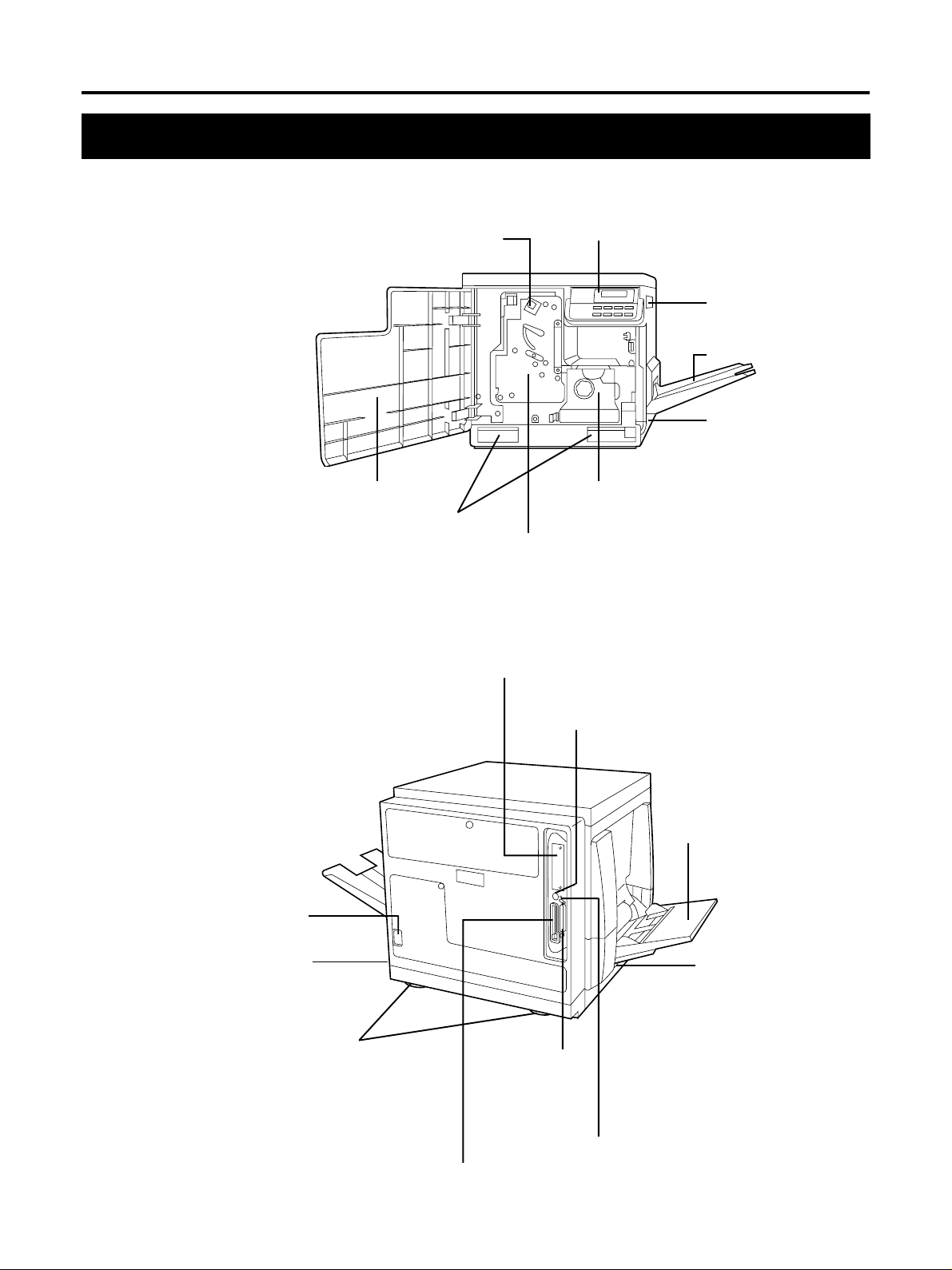
Part Names
■ Front side view
Before Y ou Start
■ Rear side view
Main Charger
Front cover
Moving handles
Network interface card slot
Operation panel
Right side cover
Output tray
Media cassette
( ☞ P. 16)
Fuser Kit
( ☞ P. 74)
Imaging unit
( ☞ P. 12)
AC inlet
( ☞ P. 24)
Power switch
( ☞ P. 25)
Moving handles
Serial interface connector
( ☞ P. 25)
Parallel interface
connector
( ☞ P. 24)
Harddisk access indicator
Memory card connector
( ☞ P. 57)
Multi-purpose (MP) tray
( ☞ P. 19)
Left side cover ( ☞ P. 19)
Media thickness switch*
( ☞ P. 19)
*Accessible by opening
the left side cover
7
Page 17
Before Y ou Start
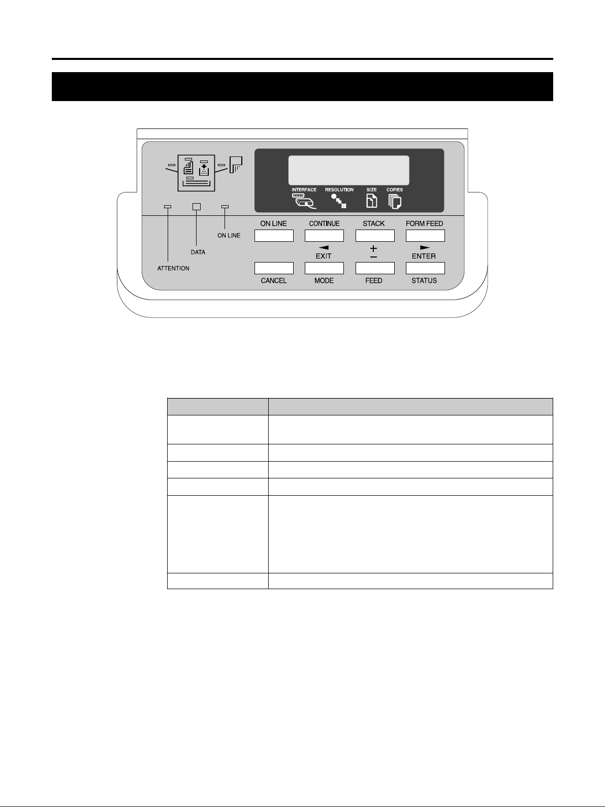
Control Panel Overview
Ready
PAR 600 A4 001
Message Display
The message display displays the printer’s operational mode. Messages which are
displayed and their meanings are given in the table below.
Message Meaning
Self test The printer is self-testing after power-up and is not ready to
print.
Please wait The printer is warming up and is not ready to print.
Ready The printer is ready to print.
Processing The printer is processing print data or in the middle of printing.
Waiting The last page remains unprinted. The printer waits awhile and
eventually generates a form feed allowing the last page to be
printed. (The length of time depends on the form feed timeout
setting.) The printing will begin immediately when the FORM
FEED key is pressed. If a memory card is being used this can indicate the printer is waiting for data to be written (☞ P. 57).
FormFeed TimeOut An automatic form feed has been generated.
8
Page 18
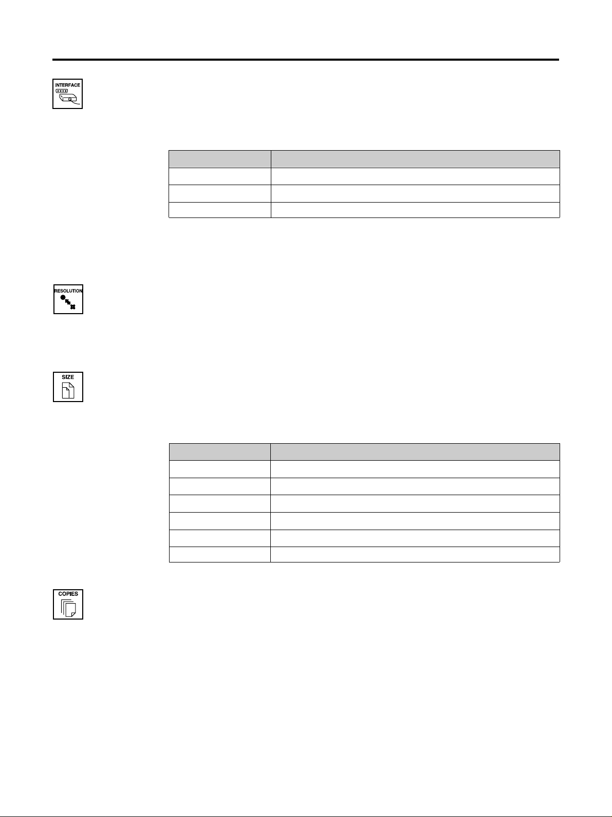
Interface Indicator
The interface indicator indicates the interface over which data is currently being received
or was last received. The current interface is indicated by one of the following messages:
Display Description
PAR Parallel interface
SER Serial interface
OPT Optional interface (if a network interface card is installed)
Note:
The display will blink while the printer is receiving data and continue blinking until
the interface is released, even after data transmission is finished.
Resolution Indicator
This shows the current printing resolution in either 1200 or 600 dpi (dots-per-inch).
Before Y ou Start
Paper Size Indicator
This indicator indicates the paper size of the cassette currently selected. The following
abbreviations are used to indicate the paper sizes:
Indicator Paper Size
A4 ISO A4 (21 × 29.7 cm)
EX * Executive (7-1/4 × 10-1/2 inches)
B5 * JIS B5 (18.2 × 25.7 cm)
LT Letter (8-1/2 × 11 inches)
LG Legal (8-1/2 × 14 inches)
b5 * ISO B5 (17.6 × 25.0 cm)
* These paper sizes can only be used in the multi-purpose (MP) tray.
Copy Indicator
This indicator indicates the number of copies to print from 001 to 999. This number is
reduced as printing proceeds.
9
Page 19
Before Y ou Start
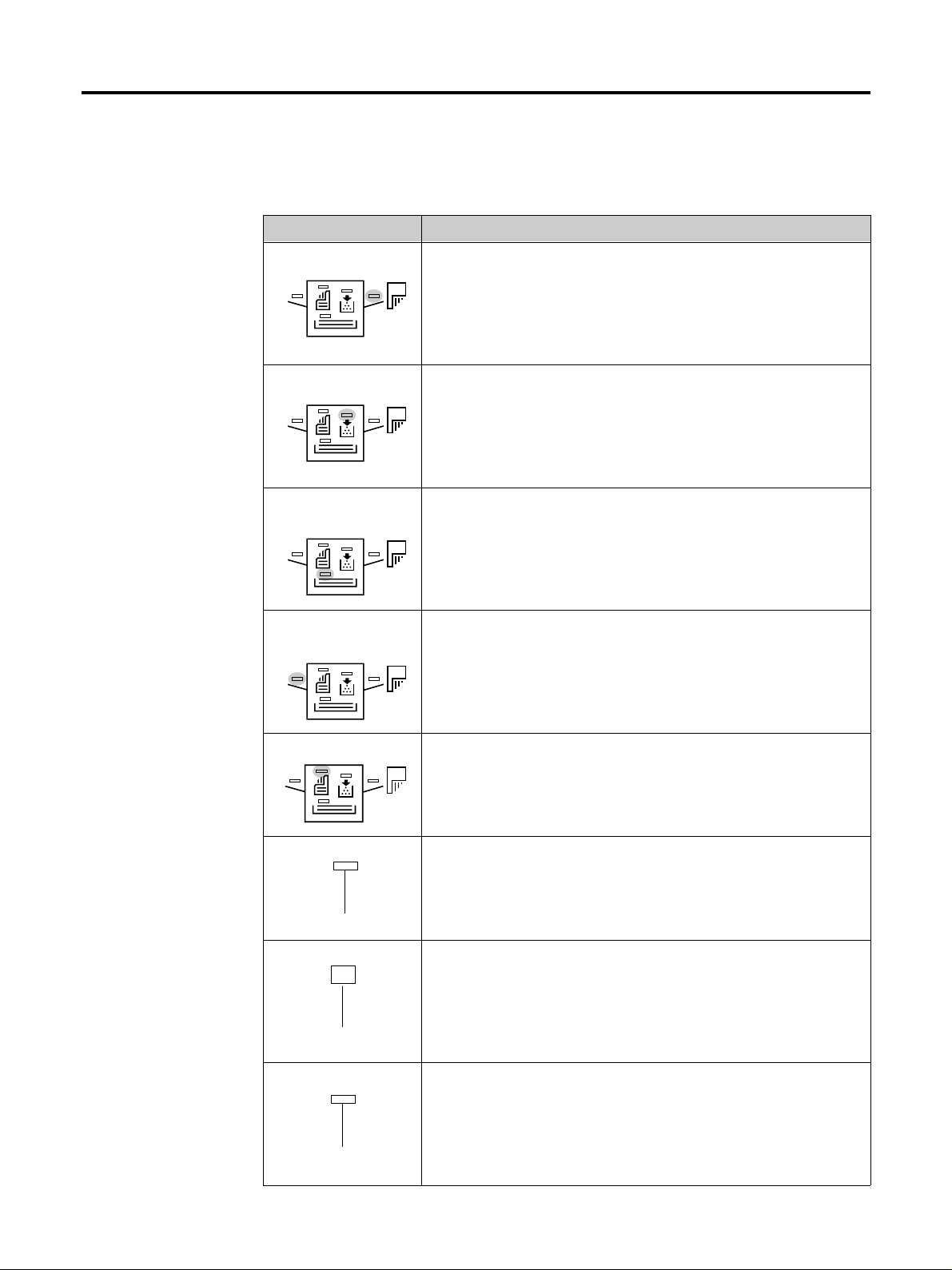
Symbolic Indicator
This printer icon includes the indicators which show the following information regarding
the printer’s paper and toner status.
Face-down indicator Indicates when printed pages are delivered to the output tray
Toner indicator Indicates the status of toner supply in either color of cyan, ma-
Cassette feed Indicates paper is being fed from the media cassette.
indicator When flashing, it indicates that there is no media in the
Name Description
in the face-down stack (correct order). The pages are delivered
in the reverse order when this indicator is not lit. If flashing, it
indicates that paper is jammed on the output tray.
genta, yellow, or black. The toner supply is normal when this
indicator is off. If flashing, the toner supply is dwindling. If
this is lit, it indicates that the printer is out of toner and not
operative until the appropriate toner cartridge is replaced (☞
P. 69).
cassette or that media is jammed in the media cassette.
Multi-purpose feed Indicates when media is fed from the multi-purpose feed tray.
indicator If this is flashing, it indicates that there is no media in the tray
or that media is jammed on the multi-purpose tray.
Duplex Indicator Indicates when media is being fed from the duplex unit. It
flashes when there is no media in the duplex unit, or when the
media is jammed in the duplex unit.
ON LINE indicator When lit, it indicates that the printer is on-line (The printer
prints received data). When this is off, the printer is offline
(The printer stores but does not print received data).
ON LINE
DATA indicator Flashes when data is arriving at the printer’s interface. When
lit continuously, it indicates that data is being processed for
printing (or that data is being written to the memory card).
DATA
ATTENTION indicator Flashes when the printer needs maintenance
(☞ P. 69). When lit continuously, it indicates that the printer
cannot print due to an error.
10
ATTENTION
Page 20
Control Keys
Before Y ou Start
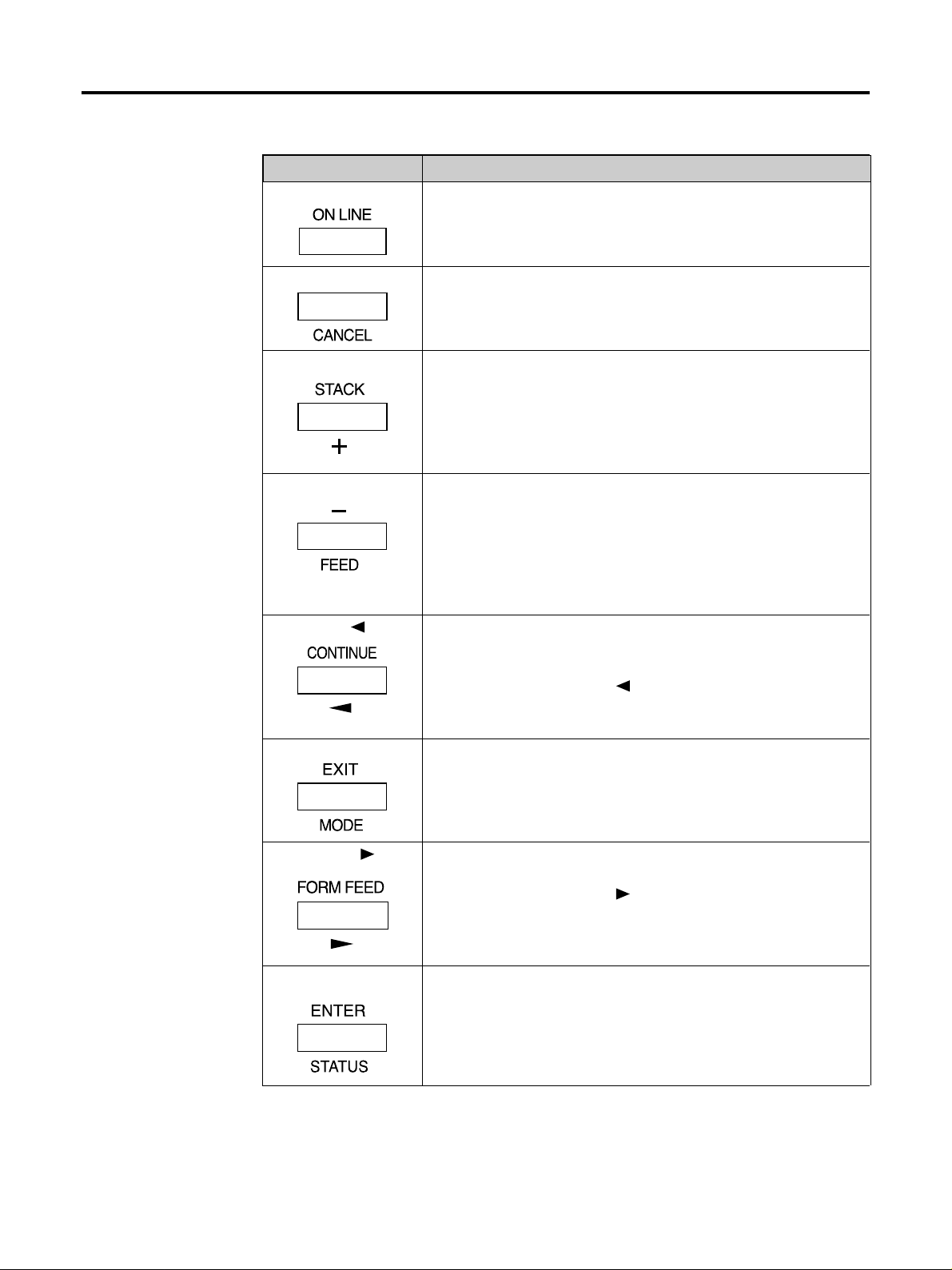
Key Function
ON LINE This key toggles the printer on-line and off-line.
CANCEL This key cancels the data processed in the printer during print-
ing. When the printer is in a mode selection sequence (See
MODE key below), pressing this key abandons mode selection
in course.
STACK/+ • This key selects whether to output media face-down (printed
side down) or face-up (printed side up).
• During a mode selection sequence, this key is used to select
menus and change setting values.
FEED/- • This key selects the paper feed cassette or multi-purpose tray
as the paper source. It can also select an optional feeder if
one is installed.
• Select the alternative paper source when Use alternative?
is displayed.
• During a mode selection sequence, this key is used to select
menus and change setting values.
CONTINUE/ • In normal operating mode, this key forcibly cancels errors
and resumes printing when printing is halted due to errors
such as memory overflow.
• This key functions as the
sequence: It moves the selection upward in the menu hierarchy or moves the cursor left.
EXIT/MODE This key is used to start and end a mode selection sequence.
(☞ P. 34)
key during a mode selection
FORM FEED/ • In normal operating mode, this key is used to forcibly form-
feed when a print timeout occurs.
• This key functions as the
sequence: It moves the selection downward in the menu hierarchy or moves the cursor right.
ENTER/STATUS • During a mode selection sequence, this key confirms the set-
ting made in the mode selection.
• This key determines the paper source while Use alternative?
is being displayed.(☞ P. 94)
• In normal operating mode, this key prints a status page.
key during a mode selection
Notes
• Menus set using these keys are enabled only for the interface currently indicated on
the message display.
• Settings made from the control panel may be automatically switched to different
settings by application software being used.
11
Page 21
Setup
Setting Up the Printer
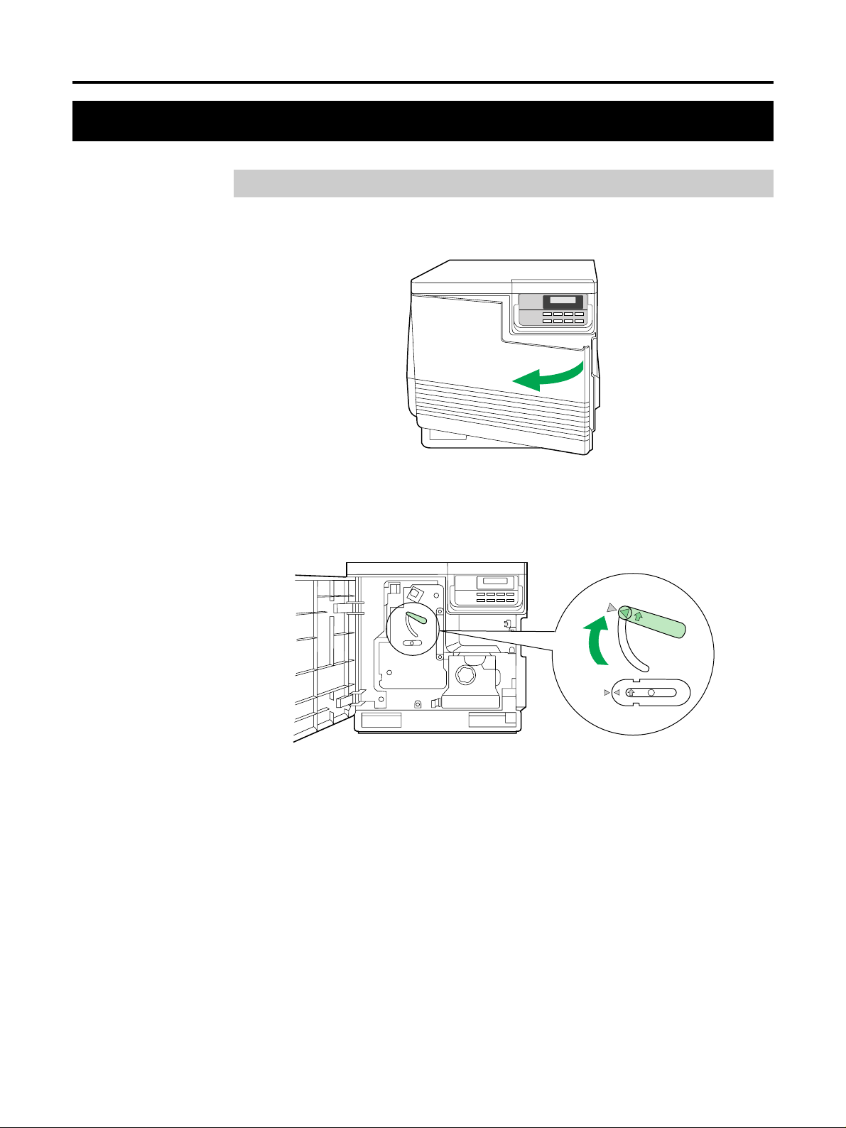
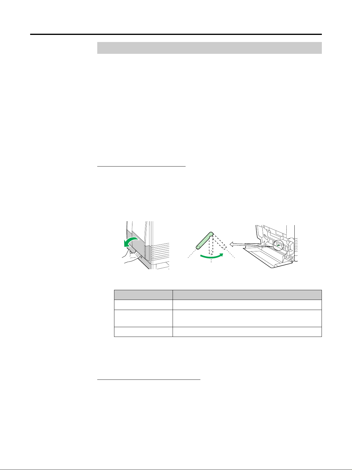
Preparing the Imaging Unit
1
Open the front cover.
Turn the upper green lever clockwise until it stops and the arrows
2
are aligned. (This tightens the internal belts, ensuring the unit is
ready for printing.)
Close the front cover.
3
12
Page 22
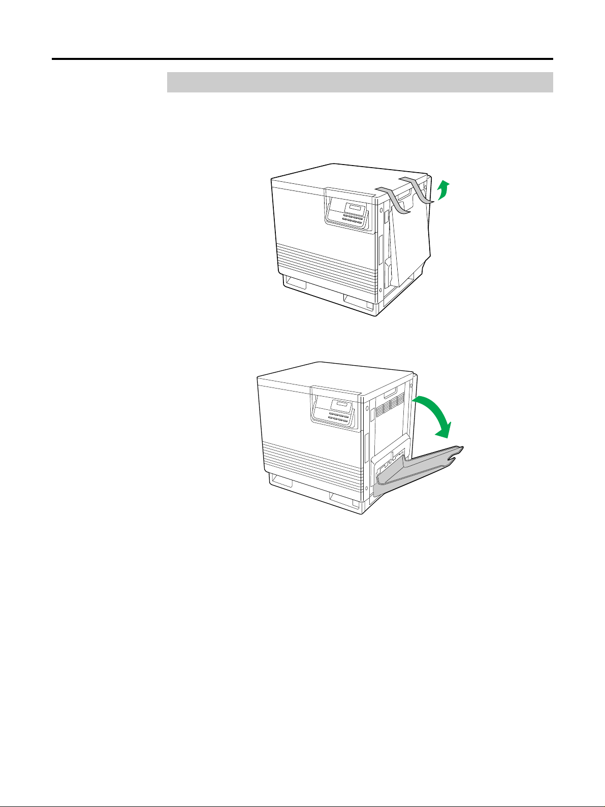
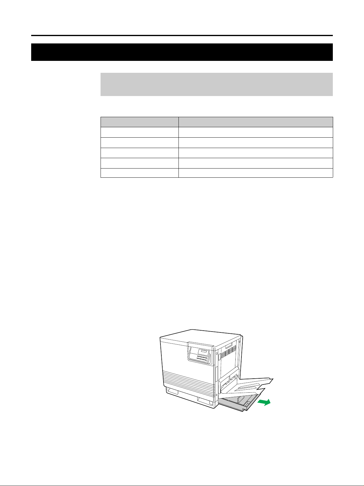
Setting Up the Output Tray
Remove the adhesive tape that holds the output tray against the
1
printer.
Setup
Lower the tray to the operating position.
2
13
Page 23
Setup
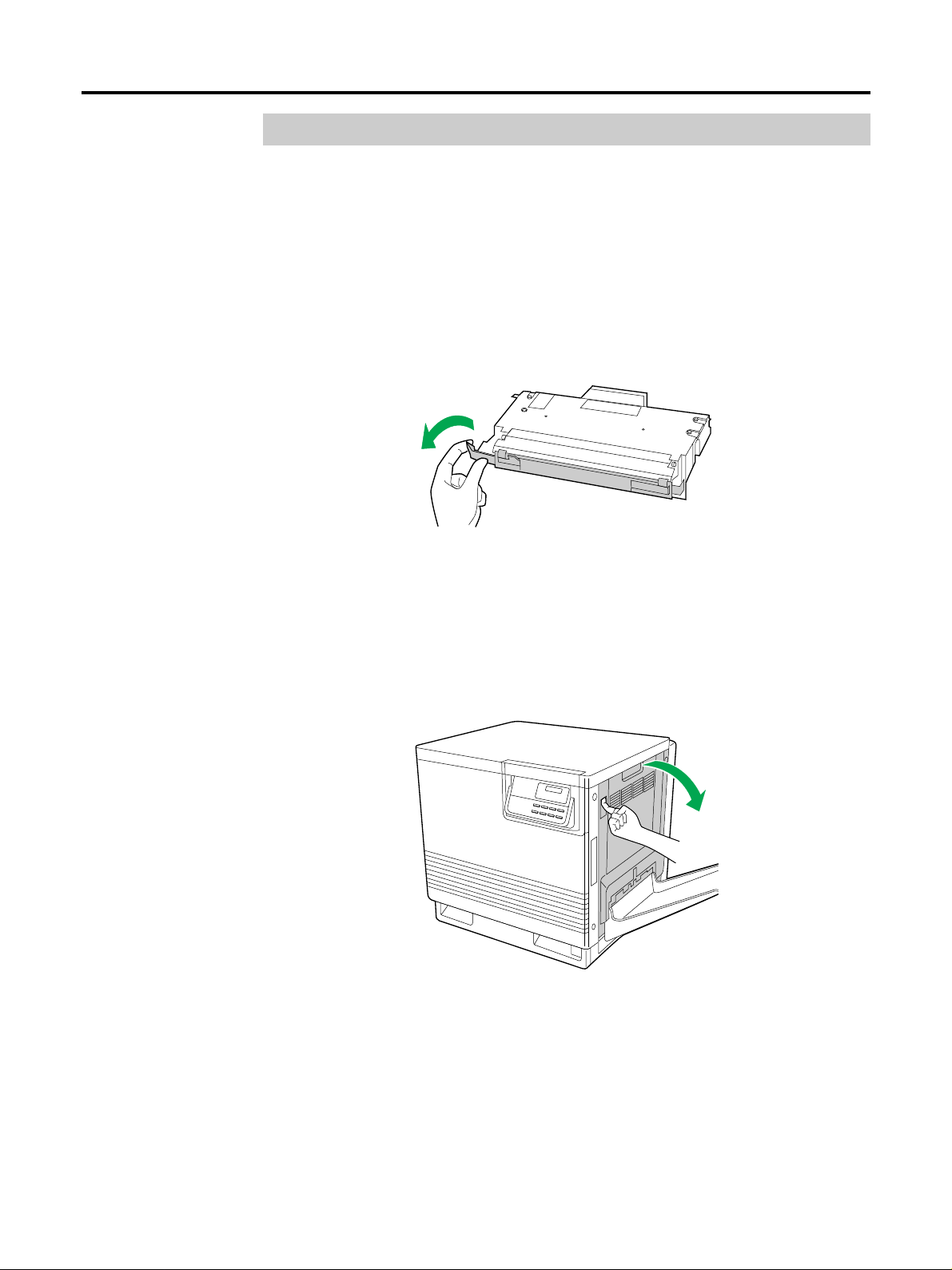
Installing the Toner Developers
Note:
The toner developers that are shipped with the printer are starter developers. They
are installed in exactly the same manner as the optional developers; the only
difference is that the starter developers have less toner. (The page life expectancy is
5000 pages for color and 6000 pages for black, both based on a 5% image area.)
Remove the packaging from the toner developer.
1
Remove the shipping cover from the developer.
2
Caution:
To avoid possible toner spillage, do not tilt developer.
Note:
Save all packing material for shipping purpose.
Open the right side cover.
3
14
Page 24
Setup
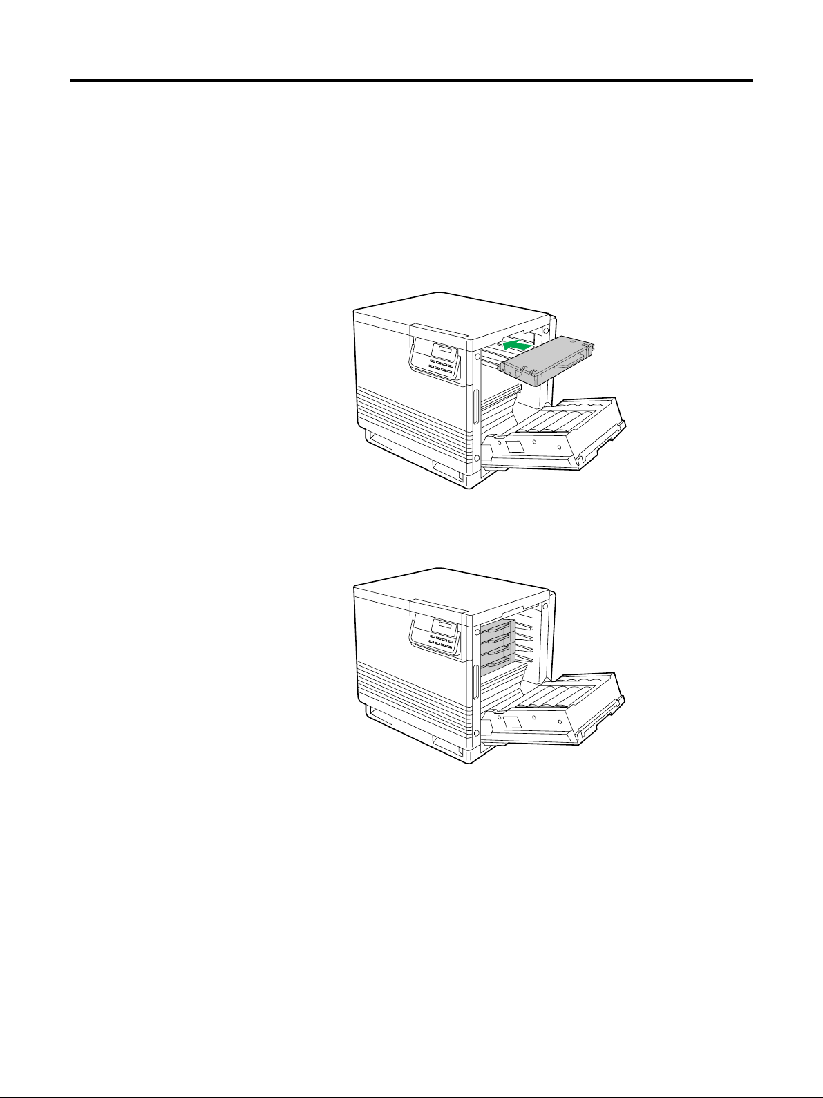
Insert the toner developer in the appropriately labelled slot.
4
From top to bottom, the order of the color toner developers is BLACK, CYAN,
MAGENTA, YELLOW.
Caution:
Excessive exposure to light will damage the imaging unit; do not leave the right side
door open for more than 1 minute. Close the right side door after replacing each
individual toner developer unit.
Repeat steps 1 to 4 for each toner developer.
5
When you have installed all the toner developers, go to step 6.
Close the right side cover.
6
15
Page 25
Setup
Loading Media
Loading Paper or Transparencies in the Media
Cassette
The printer is shipped with a media cassette (either Letter paper or A4 paper) installed.
The printer can also use five different trays as options:
Cassette Size
A4 Paper 210 mm × 297 mm
A4 Transparency 210 mm × 297 mm
Letter Paper 8.5" × 11"
Letter Transparency 8.5" × 11"
Legal Paper 8.5" × 14"
Notes:
•
Make sure that you load the correct media. Each tray is designed and labelled for
only paper or transparency. If you load the incorrect media type in a tray, it may
cause a jam.
•
If you have the Lower Feeding Unit installed:
–
If you wish to use the automatic cassette-switching feature (for example, when
doing a large print job), make sure that all cassettes in the printer are the same
media type (paper only) and size.
– The transparency cassette should only be inserted in the upper or middle cassette
slots.
Note:
The printer does not automatically switch cassettes if the media type of the cassette is
Transparency.
Pull the media cassette out of the printer.
1
16
Page 26
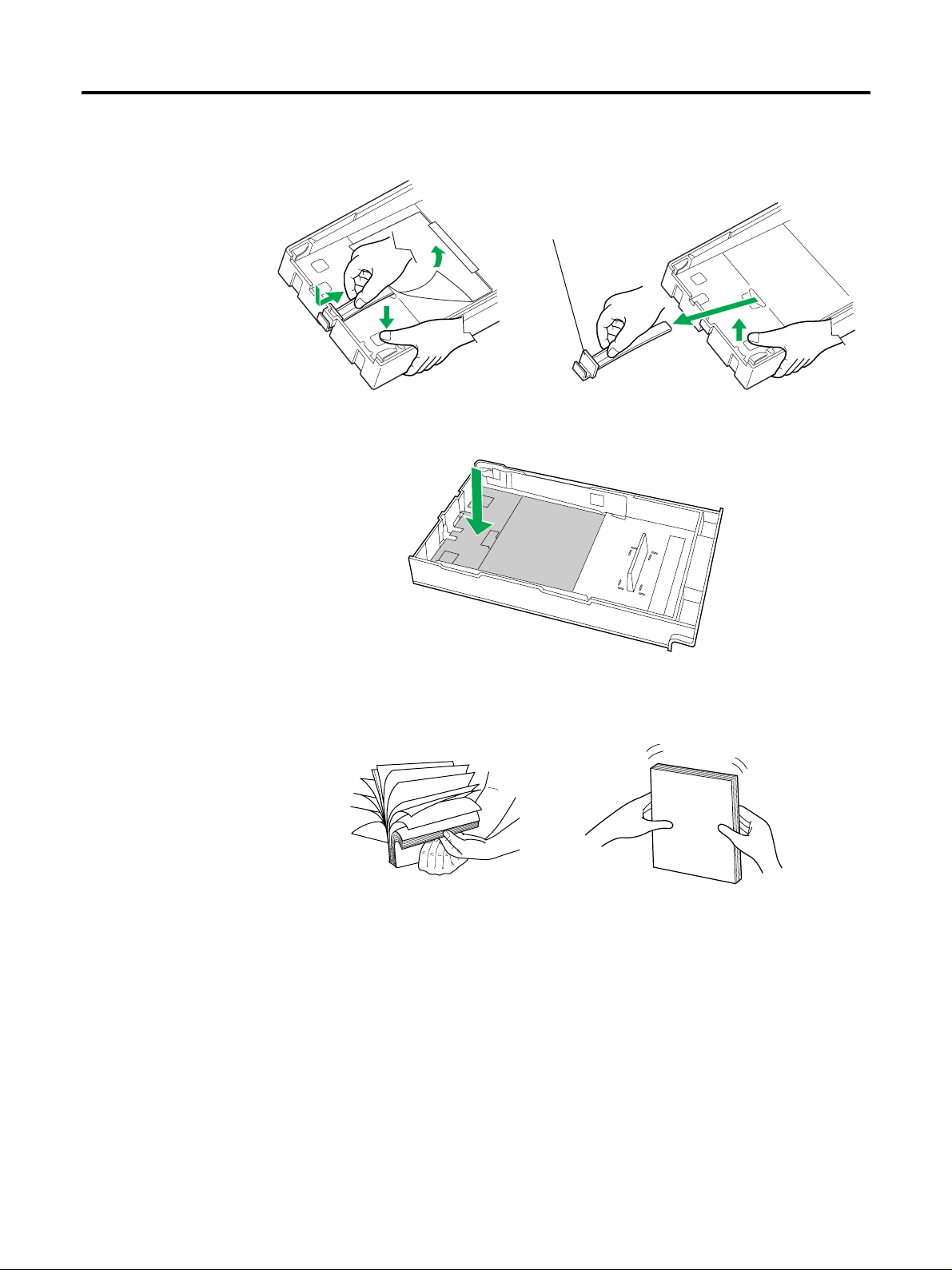
Remove the base plate stopper from inside the media cassette; refer
2
to the instruction sheet attached to the cassette.
Setup
(1)
(3)
Push down on the metal plate until it clicks, locking it in place.
3
Fan the media (paper/transparencies), then tap it on a level surface
4
to avoid media jams or skewed printing.
(2)
Base plate stopper
(4)
(5)
Notes:
•
To optimize your printer’s performance, always use clean, unused media.
•
Be careful not to leave fingerprints on the media, which can result in a smudged
print.
•
Reusing media that has been fed through the printer once (for example, after jams)
can reduce the life of the consumables and paper path components.
•
Recommended transparency types are 3M CG3700 and 3M CG3710. If the print
quality is poor, print on the other side.
17
Page 27
Setup
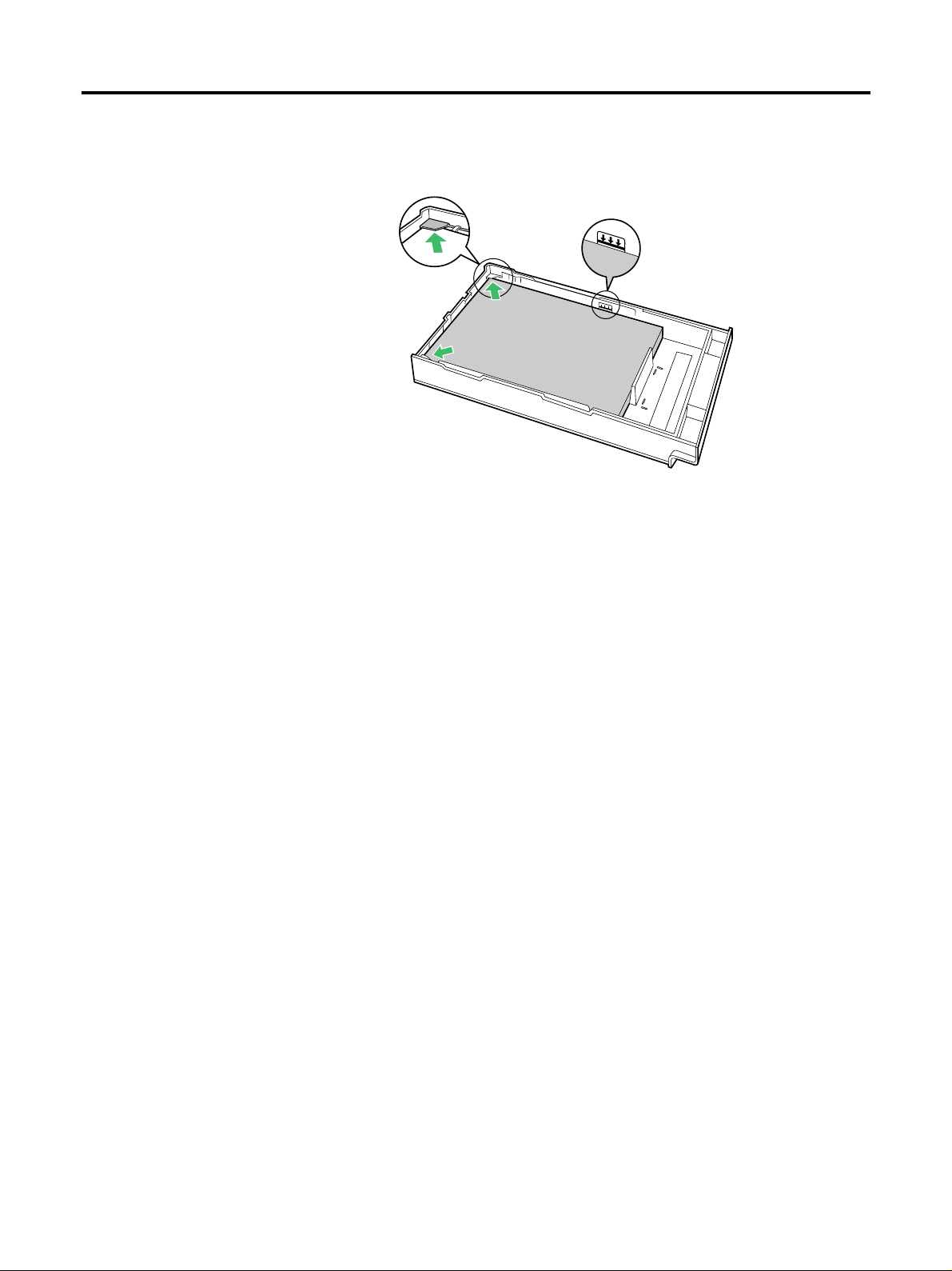
Place the media in the cassette under the hooks.
5
The height of media should not exceed the limit mark on the cassette, or it may
cause a jam.
Hook
Limit mark
Notes:
•
Load media with the print side down. Most media has instructions recommending
the side to be printed first.
•
Do not mix different types or thicknesses of media in the media cassette at one time;
this may cause a jam.
Slide the media cassette all the way into the slot.
6
18
Page 28
Setup
Loading Media in the Multi-purpose Tray
The multi-purpose (MP) tray serves as an additional tray for loading any type of media
that ranges in size from 91 mm × 254 mm to 216 mm × 356 mm (3.6≤ × 10 ≤ to 8.5≤ × 14≤
inches). Use it to load a single sheet or a stack of media, depending on the media’s type
and thickness.
Use the multi-purpose tray to accomplish the following:
Print on standard and special media
•
Standard media
Plain paper [75 to 165 g/m
•
Special media
Label, transparency, card stock, coated paper, or the reverse side of printed paper
(The print quality may not be stable. Use the media tray for best reliability.)
Setting media thickness switch
Because the printer accommodates various media weights from the multi-purpose tray,
media thickness can be manually selected for the most reliable paper-picking. Follow
these steps:
2
(20 to 44 lbs.)]
Open the left side cover ( (1) ). The green media thickness switch is
1
located on the paper feeder and has three settings:
(1)
Thin
Move the switch to the desired setting.
2
Switch setting Media
Thin (Default) Laser paper 75 to 90 g/m2 (20 to 24 lbs.)
Middle
Thick Laser paper 124 to 165 g/m2 (33 to 44 lbs.)
Close the left side cover.
3
Laser paper 91 to 123 g/m
Transparency, Label, Coated paper
Middle
Thick
2
(25 to 32 lbs.)
Selecting a multi-purpose tray mode
The multi-purpose tray has two different ways of feeding media: Cassette, and First
modes. For details on selecting a mode, refer to page 46.
19
Page 29
Setup
■ Loading Paper
Notes:
•
Reusing media that has been fed through the printer (for example, after jams) can
reduce the life of the consumables and paper path components.
•
When printing legal size using the multi-purpose tray, backside marking may occur.
If this occurs, use the legal cassette.
For detailed information on media, refer to pages 111 and 114.
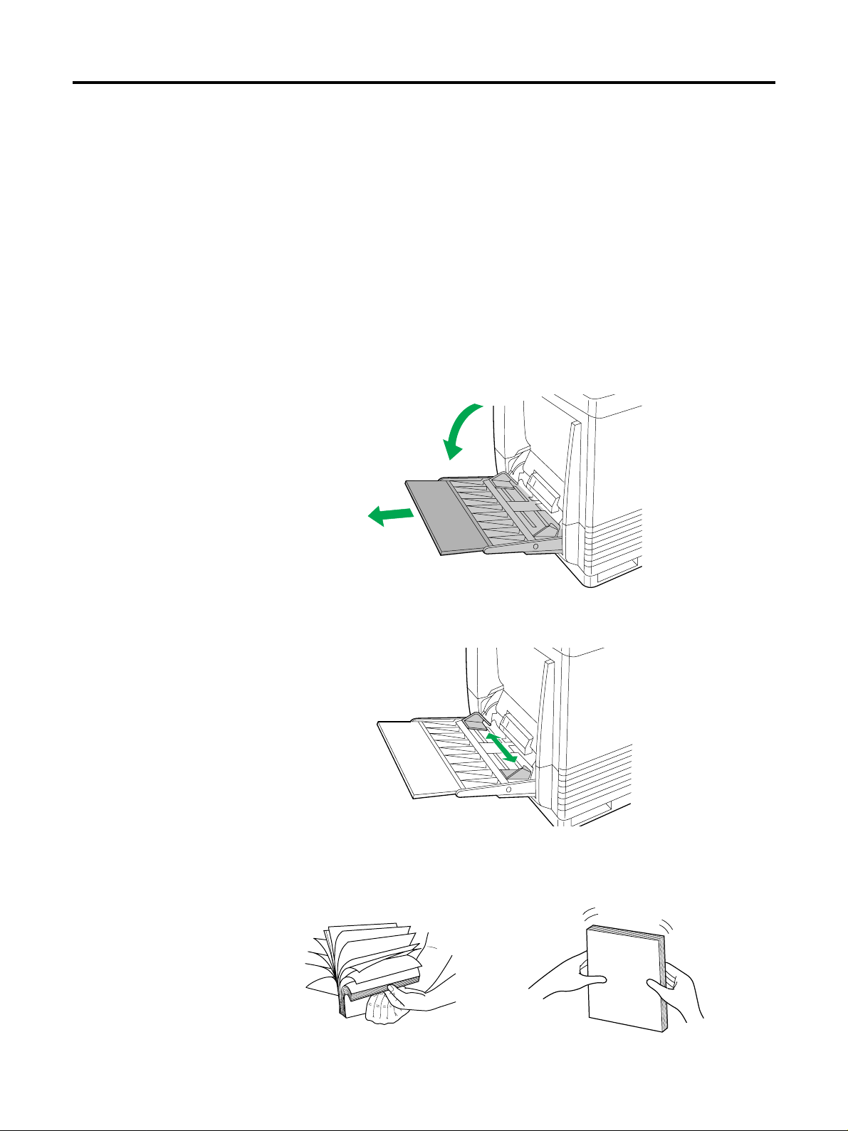
Set the media thickness switch ( ☞ P. 19).
1
(1)Open the Multi-purpose tray.
2
(2) Extend the media support by sliding it outward.
(1)
(2)
Separate the media guides to the approximate width of the media.
3
Fan the media, and then tap it on a level surface to avoid media
4
jams or skewed printing.
20
Page 30
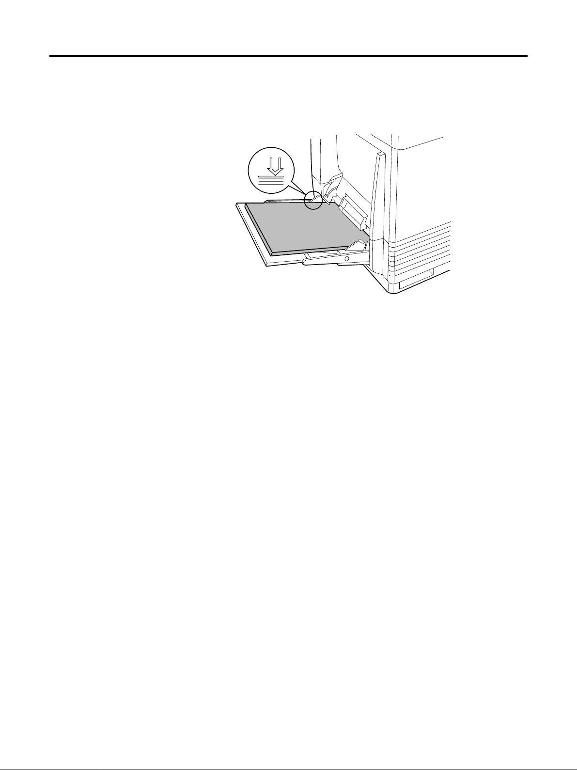
Insert the media with the printing side up into the multi-purpose
5
tray.
The height of media should not exceed the limit mark on the left guide, or it may
cause a media jam.
Adjust the media guides to the media size.
6
Setup
Use the printer driver to select the multi-purpose tray.
7
Open the printer driver’s Paper tab, then pull down the Paper
8
Source menu and select your media type.
Note:
If you use the MP tray and print on the second side of the thick paper, select Card
Stock in the Paper Source menu, instead of Second Side.*
* Means the other side of a preprinted sheet.
21
Page 31

Setup
■ Loading Label
For detailed information on labels, refer to page 114.
Set the media thickness switch ( ☞ P. 19).
1
Adjust the media guides to the width of the label sheets.
2
Load label stock into the multi-purpose tray, positioning the sheets
3
so that the top edge feeds into the printer first and the printable
side is facing up.
The height of the labels should not exceed the limit mark on the paper guide.
Open the printer driver’s Paper tab, then pull down the Paper Source
4
menu and select Label.
22
Page 32

Connecting the Printer to a Computer
The printer can directly be connected to a computer through the parallel interface or the
serial interface.
To connect the printer in a local area network, you must obtain a network interface card
(☞ P. 5). For further details, consult your dealer from which you purchased the printer.
Ci 1100 Computer Monitor
Setup
23
Page 33

Setup
Using a Parallel Interface Cable
If you do not have a parallel interface cable, you will need to purchase one from your local
computer store or dealer (☞ P. 116 for Parallel Interface specifications).
Make sure the computer, printer and the other connected peripheral
1
devices are turned off.
Connect the parallel interface cable to the computer’s parallel
2
interface connector and the printer’s parallel interface connector
(marked as Parallel).
Computer’s parallel
interface connector
Notes:
•
The actual connector on the computer may vary depending on the manufacturer of
the computer. Consult the computer’s documentation.
•
If the cable is connected to the PC via a printer buffer or selector, the printer may
not print.
Connect the power cord to the printer’s AC inlet and to an AC outlet.
3
Parallel interface
cable
24
Power cord
Page 34

Setup
Connecting the Serial Interface
To connect the printer to a computer using the serial interface, use the XSER connector
at the rear panel of the printer. The serial connector is of a round, 8-pin DIN type and
you will need a cable adaptor if you connect a DSub type serial connector.
Barcode Reader
With the hard disk option (see below) installed, you can take the advantage of the MPS
(Multiple Print System). The barcode reader then allows you to recursively print the jobs
cached in the hard disk by reading the barcode printed on the printed job. For more
information, refer to the Instruction Handbook supplied with the barcode reader.
Installing the Hard Disk Drive Option
The printer can be optionally installed with a hard disk drive. Once the hard disk is
installed, the printer can temporarily or permanently cache the print jobs in the hard
disk so that you can print multiple collated copies quickly or take the advantage of the
barcode reader system. (See the preceding section.)
Installing the hard disk drive option requires removal of the main controller board and
mounting the hard disk on it and therefore requires a qualified technician. See your
dealer from which the printer is purchased for installing the hard disk.
Power On
Turn ON the printer, then the computer. The printer’s power switch
1
is located at the bottom rear of the printer.
Back side
(1)All the indicators on the printer lights briefly and Self test is
2
displayed on the printer message display.
(2) After approximately 5 minutes, the ON LINE indicator is
illuminated and Ready is displayed on the printer message
display.
The printer is ready for printing.
Note:
When you power on your system for the first time, if “New Hardware Found” is
displayed on the computer screen, refer to page 28
.
Caution:
If the printer will not be used for a short period of time (overnight, etc.), turn the
main switch OFF (O). If it will not be used for an extended period of time (vacations,
etc.), remove the power plug from the outlet for safety purposes during the time the
printer is not in use.
25
Page 35

Setup
Printing a Status Page From the Printer Control Panel
The status page provides general information on printer settings and configuration.
Make sure the printer is ready and paper is loaded. Use the following procedure to print
a test page.
While the message display indicates Ready, press the STATUS key.
The printer will start printing a status page.
(Example)
26
The printer can also print a different status page for service purposes. To print a service
status page, see page 36, then 50.
Page 36

Installing the Driver Software
Driver software installation will create a printer driver for Windows 95 or Windows 98.
The supplied printer driver floppy disk contains KPDL printer drivers for Windows 95
and Windows 98, and a common PCL printer driver all in compressed form. Extracting
and installation methods for Windows 95 and Windows 98 are the same.
Extracting the Driver Software
Start Windows 95/Windows 98.
1
Close all applications.
2
Insert the supplied printer driver floppy disk into your floppy disk
3
drive.
Setup
Double-click My Computer and then the floppy disk drive. A Window
4
showing the contents of the floppy disk is displayed.
Double-click the icon for the printer driver to be extracted.
5
In the Unzip To Folder box, specify the directory to which the printer
6
driver is to be extracted.
Click Unzip. The printer driver will be extracted to the specified
7
directory. When extraction is complete, click OK and then CLOSE. If
required, go back to step 5 and extract another driver.
27
Page 37

Setup
Installing the Printer Driver for Windows 95/
Windows 98
■ Using Plug and Play
Turn on the printer.
1
Turn on the computer and start Windows 95/Windows 98.
2
The New Hardware Found window is displayed for a few seconds, then the Update
Device Driver Wizard window is displayed.
Click Next >.
3
Click Finish.
4
The Insert Disk window is displayed.
Click OK.
5
The Copying Files window is displayed.
In the Copy File box, type in \drivers\pcl\95 after the directory
6
path specified in step 6 on page 27.
Example: If the driver was extracted to C:\Windows\Temp in step 6 on page 27,
the complete directly path becomes
C:\Windows\temp\drivers\pcl\95
Note:
To install the KPDL printer driver, type in “kpdl” instead of “pcl” followed by \95 or
\98 depending on the Windows version that you use.
Examples: If you use Windows 98 and the driver was extracted to
C:\Windows\Temp in step 6 on page 27, the complete directly path becomes
C:\Windows\temp\drivers\kpdl\98.
Click OK.
7
Click on Mita Ci1100 Enhanced.
8
Click Next >.
9
28
Follow the instructions on the screen to complete the installation.
10
After installation, restart your system.
Note:
The Plug and Play installation procedure varies depending on the version of Windows
95/Windows 98. Refer to Help in Windows 95/Windows 98.
Page 38

■ Using Add Printer
Start Windows 95/Windows 98.
1
Quit all applications.
2
Click Start, move the pointer to Settings, then click Printers.
3
The Printers window is displayed.
Double click the Add Printer icon.
4
The Printer Wizard screen starts.
Click Next >.
5
Select Local printer or Network printer and then click Next>.
6
Click Have Disk....
7
Setup
In the Copy File box, type in \drivers\pcl\95 after the directory
8
path specified in step 6 on page 27.
Example: If the driver was extracted to C:\Windows\Temp in step 6 on page 27,
the complete directly path becomes
C:\Windows\temp\drivers\pcl\95
Note:
To install the KPDL printer driver, type in “kpdl” instead of “pcl” followed by \95 or
\98 depending on the Windows version that you use.
Examples: If you use Windows 98 and the driver was extracted to
C:\Windows\Temp in step 6 on page 27, the complete directly path becomes
C:\Windows\temp\drivers\kpdl\98.
Click OK.
9
Click on Mita Ci1100 Enhanced.
10
Click Next >.
11
Follow the instructions on the screen to complete the installation.
12
After installation, restart your system.
Note:
After installing the printer driver, it will take several minutes for the printer to
register and display in Printers Folder.
29
Page 39

Setup
Setting the Color Density
The printer panel provides an interface to adjust the density of the toner applied to the
media. This makes it possible to offset changes in density that may result due to varying
environmental conditions or aging of the toner or imaging unit.
Perform the following steps to adjust the color density:
(2), (4)
(3)
(5), (6)
(1)
Begin by printing a Color Calibration Page. To print a Color
Calibration Page, proceed as follows:
(1)Press the MODE key on the printer panel.
1
(2) Press the + key repeatedly until the message display indicates
Color Calibration.
Color >
Calibration
(3)Press the key.
(4)Press the + key until the message display shows >Print
Calibration Page.
>Print Calibration Page
(5)Press the ENTER key. A question mark (?) will appear.
30
(6) Press the ENTER key again.
A Color Calibration Page will be printed.
Page 40

Setup
The current density setting for each color is indicated by four stripes of cyan, magenta,
yellow, and black (from left to right). On the Color Calibration Page as shown in the
following example.
The factory default setting for each color density is 10.
Color Calibration Page (Example):
31
Page 41

Setup
10
10
10
10
Compare the current color density settings on the Color Calibration
2
Page with the color density samples on the Color Calibration
Reference to see if they match.
Place the Color Calibration Page on at least 2 sheets of clean white paper in a
well-lighted area.
Color Calibration
Color Calibration
Reference
If they match, you do not need to adjust the color density. If they do not match, go to step
3.
Page
Press the + key until the message display shows >Cyan. The current
3
density setting for cyan is indicated (the default is 10).
(1) Press the ENTER key.
>Cyan
10
(2)Press the + or - key to darken or lighten the cyan color.
For example:
• If you wish to make the density setting darker:
– Press the + button (up to 20).
• If you wish to make the density setting lighter:
– Press the - button (to 00).
(3)Press the ENTER key.
32
Page 42

Press the + or - key until >Print Calibration Page is indicated.
4
Press the ENTER key twice to reprint the Color Calibration Page.
5
• Repeat step 3 above, if necessary.
Repeat steps 3 through 5 for each color (MAGENTA, YELLOW,
6
BLACK).
• To skip a color, press the + button.
• To return to a previous color, press the - button.
When the Color Calibration Page and the Calibration Reference
7
match in all four colors, press the MODE key to finalise the
calibration procedure.
Notes:
•
The color density setting affects the average life of toner.
•
Save the Color Calibration Reference for future calibrations.
Setup
33
Page 43

Using the Printer
PCL 5C
Bitmap and
Scalable Fonts
Scalable Fonts
Only
ISO-6 ASCII
ISO-11 Sweden
ISO-15 Italian
ISO-17 Spain
ISO-21 Germany
ISO-60 Norway
ISO-69 France
HP Roman-8
ECMA-94 Latin 1
US Legal
IBM PC-8
IBM PC-8 (D/N)
IBM PC-850
ISO-4 U.K.
Ventura math
Ventura int'l
Ventura US
PS math
PS text
Math8
Pi font
MS publishing
Windows
Desktop
ISO Latin 2
ISO Latin 5
Windows Latin 1
Windows Latin 2
Windows Latin 5
PC-852 Latin 2
PC-Turkish
Macintosh
ISO Latin 9
Mode Selection
This section explains the menu levels and options which can be set using the MODE key. The MODE key can be used
to display all of the menus in the following table.
Ready
PAR 600 A4 001
MODE
Parallel
Serial
Option
Number of copies
PCL 5C
Emulation >
KPDL
KPDL (AUTO)
Font >
Bitmap
Scalable
Page orientation
Portrait
Landscape
Press the MODE key.
001
>Interface
>Emulation
>Parallel I/F
>Code set
ISO-6 ASCII
>
>Print KPDL errs
Off
(*2)
On
>Bitmap font
00001
>
>AudreyTwo-Regular
SWC
>Size
012.00 point (s)
>Pitch
Nibble (high)
High Speed
Normal
Auto
10.00 cpi
(
(*1)
*3
)
These items will not show unless the
printer is installed with the applicable
option unit/kit.
>Baud rate
9600
>Data bits
8
>Stop bits
1
>Parity
None
>Protocol
DTR (pos.)&XON
>Barcode mode
On
Off
*1
: Depending on the emulation selected, the following
code sets are available.
RAM DISK mode >
34
Opt. ROM >
HARD DISK >
Continued on next page
>Read data
>List of partitions
>Read data
(*4)
>RAM DISK size
>Read data
>Write data
>Delete data
>Print VMB data Tray:
>List of Partitions
>List of VMB
Page 44

Continued from previous page
Using the Printer
MEMORY CARD > >Read fonts
Paper handling >
>Color mode
Color
Quick Color
Monochrome
Color >
Matching
Color >
Calibration
>Read data
>Write data
>Delete data
>Format
>List of Partitions
>MP tray mode
>MP tray size
>MP tray type
>Duplex mode
>Auto cassette
>Override A4/LT
>RGB Simulation
>Vivid mode
>Magenta
10
>Cyan
10
>Print Calibration Page
>Black
10
>Yellow
10
Life counters >
Continued on next page
>Total print
1234567
>TransferRoller >
1234567
>Imaging unit
1234567
>Fuser KIT
1234567
>Oil supply roll
1234567
>Main Charger
1234567
>Fuser cleaning >
Pad 1234567
>>Reset Transfer
roller ?
>>Reset Fuser
cleaning pad
35
Page 45

Using the Printer
Continued from previous page
Others >
>MSG language
English
>Form Feed
Time out 030sec.
>Sleep timer
060 min
>Print HEX-DUMP
>List of
resident Fonts
>Printer Reset
>LF action
LF only
CR and LF
Ignore LF
>CR action
CR only
CR and LF
Ignore CR
(
*5
(*6)
)
*2
: The printer can be set to print error data during KPDL
emulation. If this is set to On, error data will be printed
if trouble occurs during printing. This is set to Off
before leaving the factory.
*3
: The >Size menu is not available for the
LetterGothic
fonts. Use the >Pitch menu to scale
Courier
and
these fixed fonts.
*4
: The RAM DISK mode menu is not displayed when an
optional hard disk unit is installed.
*5
: Any value from 0 to 495 [seconds] in 5-second
increments. (The printer does not time out with the
value set to 0.)
*6
: Any value from 0 to 120 [minutes] in 5-minute
increments.
*7
: For service purpose only.
>Ecoprint mode
Off
On
>Resolution
>Resource prot.
Off
Permanent
Perm / Temp
>Buzzer
Off
On
>Service >
>>Print
Test page 2
>>Print
Test Page 1
>>TransferRoller
? Type X
>>Print
Status Page
(*7)
36
Page 46

Using the Printer
Navigating through the menus
The menus are in the hierarchy as shown in the diagram above. Use the + and - keys to
move between menus in the same level (“vertically” in the table). The + key shows the
next menu, while the - key shows the previous one. Change levels by using the
keys. The key moves to lower levels (sub-menus), while the key moves to higher
levels.
(2), (4), (6)
(3)
(5), (7)
(1), (8)
To change a specific item, for example, the sleep mode timeout time, proceed as follows:
and
Press the MODE key.
1
The message display will show one of the first level menus (Level 1 in the table on
pages 34 to 36) depending on the previous selection.
Press + until Others > is shown on the display.
2
Press .
3
The message display will show one of the second level menus (Level 2 in the table
on pages 34 to 36) belonging to the Others menu above depending on the previous
selection.
Press + until Sleep timer is shown on the display.
4
To change the timeout value, press ENTER.
5
If you want to abandon setting, press CANCEL, then press MODE.
Press + repeatedly to increase the timeout time; press - repeatedly
6
to decrease the timeout time until the desired timeout time (in
minutes) is displayed.
Press ENTER to confirm the new setting.
7
You can abandon the new setting by pressing CANCEL, then MODE.
To quit the mode selection sequence, press EXIT.
8
37
Page 47

Using the Printer
Outline for Menus
■ Interface menu
The Interface menu selects one of the three printer interfaces (Option is available only if
an option network interface card is installed) on which subsequent mode menu settings
become effective. The Parallel and Serial options have the second level menus as
described below.
Level 1 Level 2 Range
Interface > >Parallel I/F Auto
Normal
High speed
Nibble (high)
Level 3 Range
>Serial >Baud rate 1200, 2400, 4800, 9600 (Default),
19200, 38400, 57600, 115200
>Data bits 7 or 8 (Default)
>Stop bits 1 (Default) or 2
>Parity None (Default), Odd, Even, Ignore
>Protocol DTR (pos.) & XON (Default), DTR
(positive), DTR (negative),
XON/XOFF, ETX/ACK
>Barcode mode Off (Default) and On
>Option*
* Displayed only when network board or other option board installed.
Parallel Interface Mode
The parallel interface mode of this printer supports a bi-directional/high-speed mode.
Display Description
Nibble (high) The parallel interface is in high-speed/bi-directional mode in com-
pliace with the IEEE1284 standard (Default).
Auto The printer automatically changes its communication mode to the
one the host computer is using.
Normal The parallel interface is configured according to standard specifi-
cations. Use this setting when conventional timing must be used.
High speed The parallel interface is in high-speed mode.
After setting the interface, be sure to reset the printer or turn the power off at least once.
The new setting will be enabled thereafter.
38
Page 48

Using the Printer
■ Number of copies
The Number of copies menu sets the number of copies to be printed.
Level 1 Range
Number of copies 001 (Default) to 999
■ Emulation
The Emulation menu switches the printer emulation. KPDL is implementation of the
Adobe’s PostScript language. KPDL (AUTO) automatically switches the printer
emulation.
Level 1 Range
Emulation PCL 5C
KPDL
KPDL (AUTO)
Notes:
• For details about the emulation menu, see the table marked “*1” on page 34.
• The printer can be set to print error data during KPDL emulation. If this is set to
On, error data will be printed if trouble occurs during printing. This is set to Off
before leaving the factory.
■ Font
The Font menu selects the printer font. The fonts available vary depending on the
emulation.
Level 1 Range Options Description
Font Bitmap Fontnumber See Font Number on list of resident
fonts that can be printed by referring
to List of Resident Fonts (☞ P. 48).
Scalable Fontname See the tables on pages 41 to 42.
Size 004.00 to 999.75 (points)
Pitch 00.44 to 99.99 (cpi)
Note:
The >Size menu is not available for the Courier and LetterGothic fonts. Use the
>Pitch menu to scale these fixed fonts.
For example, to select the 10-point Dutch801-RomanSWM:
Press MODE.
1
Press the + key repeatedly until the message display shows Font >.
2
If the Font > menu shows Scalable, proceed to step 4. If it shows
3
Bitmap, press ENTER (The question mark appears blinking), press
+ (Bitmap changes to Scalable), then press ENTER (The question
mark disappears).
Press the key. The current scalable font is indicated.
4
39
Page 49

Using the Printer
Press ENTER.
5
Press the + key repeatedly until the font name of Dutch801-
6
RomanSWM is displayed.
Press ENTER to confirm the font selection. Press CANCEL to
7
abandon the selection.
Press MODE. This finalizes the mode menu.
8
40
Page 50

Resident Scalable Fonts
Using the Printer
41
Page 51

Using the Printer
KPDL Fonts
42
Page 52

Using the Printer
■ Page orientation
The Page orientation menu switches between portrait and landscape page
orientations.
Level 1 Range
Page orientation Portrait (Default)
Landscape
■ Option ROM
The Option ROM menu reads data in the option ROM and prints a list of them as
partitions
the printer.
Opt. ROM Read data
. This menu is available only when the option ROM is installed internally with
Level 1 Range
List of partitions
■ Harddisk
The HARD DISK menu reads, writes, and deletes data on the option harddisk. It also
allows formatting the disk and printing a list of the contents. This menu is available only
when the harddisk option is installed in the printer (See
[☞ P.25]).
Level 1 Level 2
HARD DISK Read data
Write data
Delete data
Print VMB data Tray:
List of partitions
List of VMB
Installing the Harddisk Option
■ RAM DISK mode
The RAM DISK mode menu configures an arbitrary amount of memory as a RAM disk
for use with virtual mail boxes (☞ P.52) and reading or writing data.
Level 1 Level 2
RAM DISK mode RAM DISK size
Read data
Write data
Delete data
Print VMB data Tray:
List of Partitions
List of VMB
43
Page 53

Using the Printer
■ Memory card
The MEMORY CARD menu reads, writes, and deletes data on the memory card. It also allows
formatting the memory card and printing a list of the contents. This menu is available only
when a memory card is inserted into the memory card slot at the back of the printer (☞ P.
57). For instructions on using these submenus, refer to page 57.
MEMORY CARD > Read fonts
■ Color mode
This setting controls whether the page is printed in Color (four-color), Quick Color
(three-color), on in Monochrome (black and white gray scale).
Level 1 Level 2
Read macro
Read data
Write data
Delete data
List of Partitions
Level 1 Range
Color mode Monochrome
Color (Default)
Quick Color
■ Color matching
The Color matching menu provides three color matching functions to accurately
represent the original color by giving different rendering intents.
Level 1 Options
Color matching RGB Simulation
Vivid mode
For details on each color matching function, see the table below:
Color matching mode Description
RGB Simulation Printing is done using colors most closely approximate
the monitor colors. Select the type of monitor being
used. (If your monitor is not listed, set Custom values
as appropriate for your monitor. See the monitor
documentation for appropriate values.)
Vivid mode Adjusts the brightness of colors.
44
Page 54

Using the Printer
■ Color calibration
This menu provides an interface to adjust the density of the toner applied to the media.
For details on how to calibrate toner density, see Setting the Color Density (☞P. 30).
Level 1 Level 2 Range
Color Calibration Print Calibration page
Cyan 00 to 20
Magenta 00 to 20
Yellow 00 to 20
Black 00 to 20
■ Life counters
The Life counter menu displays the printer’s page count and the supply consumption
status. This helps you know how soon you will need to replace the supplies listed below.
Reset transfer roller and Reset cleaning pad options should be used after replacing
the transfer roller. Selecting this option resets the transfer roller counter to ‘0000000.’
Level 1 Level 2 Range Level 3
1
The
Life counters Total print 0000000 to 9999999
pages
TransferRoller 0000000 to 9999999 Reset transfer
pages roller
Imaging unit 0000000 to 9999999
images
Fuser KIT 0000000 to 9999999
pages
Oil supply roll 0000000 to 9999999
pages
Main Charger 0000000 to 9999999
pages
Fuser Cleaning 0000000 to 9999999 Reset Fuser
Pad pages Cleaninig Pad
1
When a supply item is replaced with a new one, the printer automatically resets the page counter
for that item to ‘0000000.’
45
Page 55

Using the Printer
■ Paper handling mode
The Paper handling mode allows the MP tray to be configured in the same manner as
with the media cassette.
Level 1 Level 2 Options
Paper handling MP tray mode Cassette
First (Default)
MP tray size B5
ISO B5
A4
Executive
Letter
Legal
MP tray type Plain (Default)
Transparency
Labels
Cardstock
Coated
2nd side
Duplex mode none (Default)
Short edge bind
Long edge bind
Auto cassette None (Default)
Size select
1 & 2*
1 & 3*
2 & 3
1 & 2 & 3*
Override A4/LT On
Off (Default)
46
* Not selectable if the duplex unit is installed.
MP tray mode
First mode
The printer automatically feeds any paper placed on the multi-purpose tray even if
another paper source is currently selected. After the paper in the multi-purpose tray is
printed, paper will be fed from the paper source originally set. This is the factory set
default. This mode is useful when printing on a special kind of paper followed by a
normal sheet in the media cassette.
Page 56

Using the Printer
Cassette mode
Approximately 100 sheets of paper can be continuously fed.
Note:
In First mode, printing is carried out using custom size paper feed timing regardless
of the MP tray size setting.
MP tray type
When cassette is selected as the MP tray mode, the paper source is automatically selected
according to the print data. Set MP tray size and MP tray type to match the type of paper
to be loaded into the MP tray. If received print data does not match the type of paper
loaded in the paper source, the printer displays an error message (☞P.93) and printing is
interrupted.
When this occurs, printing can be resumed by loading the type of paper indicated by the
error message into the MP tray and pressing the CONTINUE key.
Auto cassette mode
The Auto cassette mode is available only when the printer is installed with the
optional paper feeder. This menu selects one of the automatic paper cassette switching
modes for normal paper. The numbers below refer the media cassettes of the printer and
the option paper feeder: 1 for the upper cassette; 2 for the middle cassette; and 3 for the
lower cassette. The Size select automatically searches all media cassettes for the
paper size commanded by the document.
Note:
The printer does not switch cassettes automatically if the media is transparency.
Override A4/LT
This sets whether to enable or disable the difference between A4 size and letter size.
Under the default setting of Off, the paper size of the paper source is matched to the
paper size given for the data, and if these differ a corresponding error message is
displayed. When this is set to On, printing is performed even if the actual paper size
differs from the paper size given for the data.
Other menus (Others)
The following settings are available by selecting Others at the end of the main menu. To
enter one of these menus, press the
■ Message language
The MSG language menu selects the language of the messages on the message display.
Level 1 Level 2 Range
Others MSG language English
2
Messages in different languages can be added by installing a ROM inside the printer electronics or
inserting a PC card in the printer’s PC card slot. For more information, see your printer dealer.
key, then the + (or -) key.
2
47
Page 57

Using the Printer
■ Formfeed timeout time
The Formfeed timeout time menu adjusts the time-out time for the occurrence of the
printer’s formfeed action. Absence of data for this period of time causes a formfeed.
Level 1 Level 2 Range
Others Form feed time out 000 to 495 (seconds)
Note:
Any value from 0 to 495 [seconds] in 5-second increments. (The printer does not time
out with the value set to 0.)
■ Sleep timer
The Sleep timer menu adjusts the period of time after which the printer’s sleep
function is activated. During “sleeping,” all indicators and the ventilating fans will go off,
conserving electricity, until an operation is made from the control panel or print data is
received.
Level 1 Level 2 Range
Others Sleep timer 000 to 120 (minutes)
Note:
Any value from 0 to 120 [minutes] in 5-minute increments.
■ Print HEX-DUMP
The Print HEX-DUMP menu prints formatted hexadecimal data codes for debugging
programs and files.
Level 1 Level 2 Range
Others Print HEX-DUMP (To print in debugging mode, press ENTER
twice.)
■ List of resident fonts
The List of resident fonts menu prints a list of all resident fonts in the printer on
several pages.
Level 1 Level 2 Range
Others List of resident fonts (To print a list of resident fonts,
press ENTER twice.)
48
Page 58

Using the Printer
■ Printer Reset
The Printer Reset menu brings all temporary printer settings back to their default
values. Note that resetting the printer also removes all temporarily downloaded
resources such as fonts and macros from its memory.
Level 1 Level 2 Range
Others Printer Reset (To reset the printer, press ENTER twice.)
■ LF action
The LF action menu selects the line feed action from the following options.
Level 1 Level 2 Range
Others LF action LF only, CR and LF, Ignore LF
■ CR action
The CR action menu selects the carriage return action from the following options.
Level 1 Level 2 Range
Others CR action CR only, CR and LF, Ignore CR
■ Ecoprint mode
The Ecoprint mode menu switches Ecoprint on or off. The Ecoprint enables you to
reduce the amount of toner consumed on the page, saving your printing cost.
Level 1 Level 2 Range
Others Ecoprint mode On, Off
■ Resolution
The Resolution menu sets the resolution of the printer.
Level 1 Level 2 Range
Others Resolution 600 dpi 1200 dpi*
Note:
* The 1200 dpi setting can be selected only when using KPDL emulation.
With emulation modes other than KPDL, 600 dpi is selected automatically.
49
Page 59

Using the Printer
■ Resource protection
The Resource protection menu enables the resource protection function in the
following options. The resource protection function preserves PCL resources in memory
so that they are intact even when you change the emulation from KPDL (or KPDL
[AUTO]) back to PCL 5C.
Level 1 Level 2 Range
Others Resource prot. Off, Permanent, Perm/Temp
■ Audio alarm
The Buzzer menu turns on the audio alarm which sounds according to the printer error.
Level 1 Level 2 Range
Others Buzzer Off, On
■ Service
The Service menu prints a special status page and color test pages to diagnose
problems. The Print Test Page 1 prints a CMYK test page; and the Print Test Page 2
prints four pages, each printed in cyan, magenta, yellow, or black.
Level 1 Level 2 Level 3
Others Service Print Status Page,
Note:
For service purpose only.
Transfer Roller,
Print Test Page 1,
Print Test Page 2
50
Page 60

Using the Printer
RAM DISK
A RAM DISK can be set up as a virtual media device by setting a given amount of the
total printer memory as the RAM DISK. This can then be used for reading and writing
data just as with a memory card or as a virtual mail box function (see page 52 to 56).
Note however that data written to the RAM DISK is lost if the printer is reset or its
power turned off. RAM DISK settings can be made from the printer’s control panel.
Notes:
• The RAM DISK is set from the printer’s user memory. The printer’s printing speed
may therefore drop or insufficient memory errors result depending on the value of
the RAM DISK setting.
• RAM DISK functions cannot be used if an optional hard disk unit is installed.
■ Setting the RAM DISK Size
Press the MODE key.
1
Press the + or - key and select RAM DISK mode >.
2
The default setting is Off. Pressing the ENTER key will cause a ? to
3
flash. Press the + or - keys to display On and then press the ENTER
key.
Press the key to display >RAM DISK size.
4
Press the ENTER key again, and change the RAM DISK size using
5
the + or - key. It is not possible to make a setting that exceeds total
printer memory. The default value for the RAM DISK is the total
printer memory minus 32 MB. This parameter may be set anywhere
from 01 to 80 depending on the available printer memory. Press the
EXIT key if you want to cancel the setting.
Once the desired RAM DISK size is displayed, press the ENTER key.
6
Press the EXIT key. Then turn the printer’s power off and on again.
7
The setting will be activated after restart.
51
Page 61

Using the Printer
■ RAM DISK Operations
The following operations are available with the RAM DISK.
• Read Data
• Write Data
• Delete Data
• Print a List of Data Names
• Print Accumulated VMB Data
• Print VMB List
Except for printing accumulated VMB data and printing a VMB list, procedures for all
operations are the same as for a memory card. Please see the memory card item for the
given procedure.
Virtual Mail Box (VMB)
The Virtual Mail Box (VMB) function is a mail box function for the printer which does not
require a physical mail box to be attached to the printer. The virtual mail box function
can be used when RAM DISK mode is On or when an optional hard disk unit is installed
on the printer. (The RAM DISK cannot be used when the optional hard disk is installed.)
This manual describes how to use the virtual mail box with a RAM DISK.
With a virtual mail box, unlike a physical mailbox, data sent from the computer is stored
in the RAM DISK as rasterized data. This stored data accumulates in a numbered virtual
output tray. When it is time to actually print the data, it is printed by specifying the
virtual output tray number where the data is stored using the printer’s control panel or
an optional barcode reader.
Note:
If all the data in a virtual output tray is printed, all data in that tray will be deleted.
If printing is halted by pressing the CANCEL key during printing, data in that tray
will not be deleted. Data is not deleted unless all data in the virtual output tray is
printed.
• Locked mailbox
Allowing a password to be set for the virtual output tray, this feature makes the
printout of confidential documents easy.
• Multilevel mailbox
Supporting up to 255 virtual output trays, mail boxes can be allocated at the
individual level rather than by the user’s job title or group.
• Large capacity mailbox
There is no limit on the size per virtual output tray. Since the only limit is on the
total size of all trays, all of the RAM DISK can be used.
52
Page 62

Using the Printer
■ Outputting to a VMB
When sending data to a virtual output tray set within the RAM DISK, make this setting
from the printer driver. With this setting, data can be sent by specifying the desired
virtual output tray number. It is also possible to assign a name to a virtual output tray
and send data by specifying that name. (For details on this setting, please refer to the
help documentation for the printer driver.)
When data is sent by specifying a virtual output tray, printing to paper is not performed
at the time data is sent. Sent data accumulates in the virtual output trays of the RAM
DISK. For details on printing accumulated data, please see the next item.
■ Print Accumulated VMB Data
This function prints VMB data accumulated in a virtual output tray.
Select RAM DISK mode on the printer’s Mode Select Menu and
1
display >Print VMB data Tray. The VMB tray number will appear in
the location marked by #’s below, while the VMB tray name will
appear in the location marked by %’s.
>Print VMB data
Tray###:%%%%%%%
Pressing the ENTER key will cause a ? to flash.
2
>Print VMB data
Tray###?%%%%%%%
Each time the + or - keys are pressed, the VMB data display will
3
change. Press the CANCEL key if you want to halt printing. The ?
display will disappear.
Display the VMB data you want to print. Pressing the ENTER key
4
will cause Processing to be displayed and the data will be printed.
53
Page 63

Using the Printer
■ Print Accumulated VMB Data with a Password
This function prints VMB data protected by a password which has accumulated in a
virtual output tray.
Display >Print VMB data Tray. The VMB tray number will appear
1
in the location marked by #’s below, while the VMB tray name will
appear in the location marked by %’s.
Pressing the ENTER key will cause a ? to flash.
2
Each time the + or - keys are pressed, the VMB data display will
3
change. Press the CANCEL key if you want to halt printing. The ?
display will disappear.
>Print VMB data
Tray###:%%%%%%%
>Print VMB data
Tray###?%%%%%%%
If a password is set for the VMB data you want to print, the message
4
display will change to >User ID? 00001 and the printer will standby
to accept a password. The cursor will blink in the one’s place of the
displayed number. Enter the correct password. Use the
keys to change places and the + or - keys to change the displayed
number. Passwords from 00001 to 65535 can be entered.
Press the ENTER key once the correct password is entered.
5
Processing will be displayed and the data will be printed. If the
password was incorrect, an error message “RAM DISK error 86” will
be displayed. (See page 97) Pressing the CONTINUE key will return
the printer to Ready status.
Note that the password entered here is reset (returns to 00001) when this mode is exited.
and
54
Page 64

Using the Printer
■ Print VMB Accumulated Data List
This feature prints a list of VMB data accumulated in the RAM DISK.
Display >List of VMB.
1
>List of VMB
Pressing the ENTER key will cause a ? to display.
2
>List of VMB ?
Press the CANCEL key if you want to halt printing. The ? display
will disappear.
Pressing the ENTER key will cause Processing to be displayed and
3
the VMB data list to be printed.
An actual VMB list printout will differ slightly from sample given above.
Information regarding virtual output trays which are set will be displayed in the virtual
mail box list. A
contain data. If a password is set for a virtual output tray, there is no barcode shown for
that virtual output tray. Also, “FULL!!” will be shown for virtual output trays for which
there was an error when data was sent to them. A VMB ERROR LOG will be printed
when data from such a virtual output tray is printed.
mark is shown with the bin number for virtual output trays which
55
Page 65

Using the Printer
■ Operations for Using a Barcode Reader
If an optional barcode reader is connected to the printer, it is possible to print data
within a virtual output tray using the barcode in the list. Select the barcode for “Output
(1)” in the upper right using the barcode reader and then select the barcode for the
virtual output tray you want to print. If you want to delete the data in a tray, select
“Delete (2)” also in the upper right and then select the barcode for the virtual output tray
you want to delete. Note that all data in the tray will be deleted.
For detailed operating procedures for the barcode reader, please read the Instruction
Handbook included with the barcode reader.
56
Page 66

Using the Printer
Memory Cards
This printer is equipped with a memory card slot. If a JEIDA Ver. 4.2 memory card is
used, it is possible to read, write and delete data, and format the memory card.
Note:
Only 32 MB or less, flash or S-RAM type memory cards, conforming to JEIDA Ver.
4.2, can be written or formatted by this printer.
Font cards can be read from the control panel or read automatically upon power-on or
printer reset when a font card is inserted in the printer.
■ Inserting a Memory Card
Warning:
When adding memory, ALWAYS remove the power plug from the outlet. If this
operation is performed with the power still attached, there is a danger of electrical
shock.
Carefully insert the memory card as far as it will go with the top (label) side facing as
shown below.
Memory Card Slot
Top Side of
Memory Card
Notes:
Follow the precautions below when handling memory cards:
• Memory cards are sensitive to static electricity. Before handling a memory card,
be sure to eliminate any static electricity which may have built up on your body
or clothing by touching a metallic object.
• Use flash memory cards or S-RAM memory cards conforming to JEIDA Ver. 4.2
which are approved by us.
• Be sure that its power is off when inserting or removing a memory card.
• Do not insert memory cards into the slot with undue force.
• Do not bend memory cards.
• Do not drop memory cards or subject them to shock.
• Do not splash water or other liquids on memory cards.
• Do not place memory cards near fires or heat sources.
• Do not subject memory cards to direct sunlight.
Store memory cards in their protective case when not using them.
57
Page 67

Using the Printer
■ Reading Data from a Memory Card
The operation described here is performed while the message display reads Ready.
Insert the memory card into the memory card slot (☞ P. 57).
1
Bring up the menu >Read font on the message display.
2
For details on using the mode selection menu, see pages 37 and 44.
Press the ENTER key. The question mark (?) will appear and a data
3
name will appear after it.
Press the CANCEL key to abandon reading data.
Press the + key to scroll through data names on the memory card.
4
Press the ENTER key again. This will cause Processing to appear
5
in the message display and the selected data will be read.
After the data have been read, the message display will return to
6
Ready.
■ Writing Data (Partitions) to a Memory Card
Up to 127 partitions can be written on a single memory card. Data written on the card
are automatically assigned names, which can be checked by printing out a partition list.
Check that the memory card is not write-protected.
Bring up the menu >Write data on the message display.
1
Press the ENTER key. ? will appear.
2
Pressing the ENTER key again will cause Processing to appear in
3
the message display followed by Waiting.
Press the CANCEL key to cancel writing data.
Send data from the computer to the printer.
4
[Example]
Sending the file TEST.PRN to the printer from the computer (DOS mode).
58
COPY TEST.PRN LPT1
The message display will change to Processing when data is received and will
change back to Waiting when reception is finished.
Note:
A printable file should be stored on the memory card.
Page 68

Using the Printer
Check that the message display has changed to Waiting and press
5
the FORM FEED key.
The printer will automatically print the data just written (example below). This
printout can be used to check the name (partition name) under which data was
written and confirm that it was written properly.
Slot number: Slot name for the memory card (only A is supported)
Data type: Data type (only 2 is supported)
Partition name: Name of the partition (data) written
Write data length: Size of the partition data written (in units of bytes)
After printing is finished, the message display will return to Ready.
■ Deleting Data from a Memory Card
It is possible to delete data on a memory card one at a time. Check that the memory card
is not write-protected.
Bring up the menu >Delete data on the message display. This
1
display only appears if the memory card contains data.
Press the ENTER key. The question mark (?) will appear and a data
2
name will appear after it.
The ? will flash, and a data name will appear.
You can scroll through data names on the memory card one by one
3
by pressing the + key.
Press the CANCEL key to cancel this operation.
Press ENTER key while the data you wish to delete is shown. The
4
message display will change to Processing. To check that the
specified partition has been deleted properly, print a partition List
(☞ P. 60).
>Delete data
? (data name)
59
Page 69

Using the Printer
■ Formatting a Memory Card
It is necessary to first format a new memory card before it can be used by the printer.
Formatted memory cards can then be written with data.
Note:
• Note that if you format a memory card which already has data written on it, that
data will be lost entirely.
• Check that the memory card is not write-protected.
Bring up the menu >Format on the message display.
1
Press the ENTER key. ? will appear.
2
Pressing the ENTER key again will cause Processing to appear in
3
the message display and the memory card will be formatted.
The printer will print memory card formatting information after initialization is
finished. Use this to check that the memory card has been formatted properly.
After this information is printed, the message display will return to Ready.
■ Printing a List of Data Names (Partitions)
This operation prints the contents (data names, data size, etc.) of the memory card
inserted in the memory card slot.
Bring up the menu >List of Partitions on the message display.
1
Press the ENTER key. ? will appear.
2
Press the CANCEL key to cancel printing.
Press the ENTER key again. This will cause printing to start.
3
After this information is printed, the message display will return to Ready.
60
Page 70

Using the Printer
■ Memory Card Error Codes
Error codes 11, 13, 17, and 18 apply only to flash memory cards.
Error code Meaning
MEMORYCARD err 01 • You attempted to write more than 32 MB of data to a
Press CONTINUE memory card. Or, the capacity of the memory card
installed in the printer is more than 32 MB.
• A data name not existing on the memory card is
specified. Check the data names on the memory card.
MEMORYCARD err 02 • This memory card cannot be used by this printer.
Press CONTINUE
MEMORYCARD err 03 The memory card is not a JEIDA card. Only JEIDA
Press CONTINUE Ver. 4.2 memory cards can be used by this printer.
MEMORYCARD err 04 The card is an S-RAM or flash card which cannot be
Press CONTINUE used by this printer.
MEMORYCARD err 05 There is no battery in the memory card. Replace the
Press CONTINUE battery in the memory card with a new one.
MEMORYCARD err 06 The memory card is write-protected. Cancel the write-
Press CONTINUE protection of the memory card.
MEMORYCARD err 07 The memory card requires formatting. Format the
Press CONTINUE memory card from the control panel (☞ P. 60).
MEMORYCARD err 09 The capacity of the memory card is insufficient. This
Press CONTINUE error code appears when an attempt is made to write
more data on the memory card than available memory.
To halt the writing of data, first stop data transmissions from the computer, and then press the printer’s
CANCEL key.
Press the FORM FEED key if the message
will appear in the message display. The message display will return to
MEMORYCARD err 11 The memory card is full of data. The number of data
Press CONTINUE which can be written on the memory card is limited to
127. Pressing the CANCEL key will restore the mes-
sage
Ready in the message display.
MEMORYCARD err 13 This is a logical error. Try substituting another flash
Press CONTINUE memory card.
MEMORYCARD err 17 The flash memory card cannot be written due to
Press CONTINUE insufficient printer memory. Either delete unnecessary
macros and/or fonts stored in the printer, or expand the
printer’s available memory.
MEMORYCARD err 18 This is a write error. Try substituting another flash
Press CONTINUE memory card.
Ready.
Waiting
61
Page 71

Using the Printer
Setting the Sleep Timer
The sleep timer can be set anywhere from 0 to 120 minutes in 5-minute increments.
Setting the sleep timer to 0 turns it off. The sleep timer is set at the factory to 60 minutes.
To set the sleep timer:
Press the MODE key on the printer panel.
1
Press the + key repeatedly until the message display indicates
2
Others>.
Press the key.
3
Press the + key repeatedly until the message display indicates
4
>Sleep timer.
The current sleep timer (in minutes) is indicated.
Press the ENTER key. The underline cursor flashes.
5
Press the + or - key to change the timer setting. You can use the or
6
7
8
Once the set time arrives, the printer will display Sleeping and all indicators will go
out. This minimizes the amount of energy used.
key to quickly change the timer setting.
Press the ENTER key to finalize the setting.
Press the MODE key to exit the mode selection menu.
Resource Protection
When you switch from the PCL 5C emulation to KPDL, all downloaded fonts and macros
are lost. Resource protection preserves these PCL resources in memory so that they are
intact when you change the emulation back to PCL 5C.
By using the printer’s >Resource prot.menu, you can select from two resource
protection modes:
62
Page 72

Using the Printer
Permanent
In this mode, the printer stores fonts, macros, symbol sets, etc. in memory that were
downloaded as permanent PCL resources. All temporary resources are lost when the
emulation mode is changed from PCL 5C to KPDL or vice versa.
Permanent and temporary
In this mode, the printer stores both permanent and temporary resources when the
emulation mode is changed from PCL 5C to another or vice versa.
To select the resource protection mode:
Press the MODE key on the printer panel.
1
Press the + key repeatedly until the message display indicates
2
Others>.
Press the key.
3
Press the + key repeatedly until the message display indicates
4
>Resource prot.
The current resource protection mode is indicated — Permanent or Perm/Temp.
>Resource prot. >Resource prot.
Permanent Perm / Temp
Press the ENTER key. The question mark (?) will appear blinking.
5
Press the + key to change from Permanent to Perm/Temp, or vice
6
versa.
Press the ENTER key to finalize the setting.
7
Press the MODE key to exit the mode selection menu.
8
63
Page 73

Care and Maintenance
Cleaning
Periodic cleaning of the printer is recommended. The frequency of cleaning is dependent
upon the environment in which the printer is used. You should clean the printer:
• At least once a month.
• When the printer experiences frequent media jams.
• When print quality has deteriorated.
Caution:
For safety purposes, ALWAYS remove the power plug from the outlet when
performing cleaning operations.
■ External
Turn the power OFF.
1
Clean all the covers with a soft cloth. Use any mild commercial
2
cleaner.
Caution:
Do not use benzine, thinner, aerosol cleaners, or any abrasive powder.
■ Internal
When using isopropyl alcohol with a lint-free cloth, make sure that the alcohol is at least
90% pure, obtainable from your local pharmacy. (Do not use rubbing alcohol; it can
damage the printer.)
Cleaning the paper-pick rollers
Slide the media tray out (you do not have to remove it) to allow
1
access to the paper-pick rollers.
Open the left side cover.
2
Use the green handles to pull out the paper feeder.
3
64
Page 74

Care and Maintenance
Gently rotate the paper-pick rollers 180° (the paper-pick rollers are
4
D-shaped) and wipe them with a lint-free cloth that has been
moistened with isopropyl alcohol.
Reinsert the paper feeder ( (1) ) and close the left side cover ( (2) ).
5
(1)
Slide the media tray back into place.
6
Cleaning the optional feeder and the duplex unit
If you have an optional paper feeder installed, you may also need to clean the rollers for
the middle and lower media trays, which are accessed through the lower left side cover.
(2)
65
Page 75

Care and Maintenance
When using the duplex unit, it may become necessary to clean the rollers inside the unit.
Open the internal cover, and wipe the rollers with a lint-free cloth steeped in isopropyl
alcohol.
Cleaning the home sensor
Open the printer’s front cover.
1
Remove the imaging unit:
2
(1) Loosen the two thumbscrews by turning them counterclockwise.
(2) Turn the lower green lever 180° counterclockwise.
(1)
(2)
(1)
66
Page 76

Care and Maintenance
(3)Grasping the front green handle, slide the imaging unit out until
it catches.
(4) Lift up the left green handle. Pull the imaging unit out of the
printer and cover it to protect it from light exposure.
Green surface
(4)
Black belt
(3)
Important:
Do not touch the green surface (the right side) or the black belt (the underside).
Finger prints may affect the print quality.
Caution:
The imaging unit weighs approximately 6.5 kg (14.3 lbs.). Always use the handles
when lifting it.
Cautions:
• Do not expose the imaging unit to artificial light for more than 45 seconds; or you
may damage the unit. Never expose it to direct sunlight.
• Do not leave the printer’s front cover open for an extended period of time (for
example, several hours).
67
Page 77

Care and Maintenance
Use a dry, lint-free cloth to wipe the slot of the sensor.
3
Reinsert the imaging unit into the printer, holding it by its green
4
handles.
Match the arrow on the right side of the imaging unit with the arrow on the
printer, and slightly push the imaging unit into the printer. Then release the left
handle and push the unit in until it stops.
Sensor
Slot
(1)Turn the lower green lever clockwise 180° to insert the unit
5
completely and to lock it.
(2) Tighten the two green thumbscrews by turning them clockwise.
(3) Close the front cover.
(2)
(2)
(1)
(3)
68
Page 78

User Replaceable Components
When the printer panel indicates that a supply needs to be replaced, make sure that you
have replacement supplies on hand. The printer may continue to print until the supply is
completely used up; then it stops until you replace the indicated supply.
Components Printer panel message Average life
Toner Developers Bl ack
Imaging Unit Monochrome
*1
These figures are based on an average of 5% coverage of the printable area and standard density
for any one color. The frequency of replacement will vary depending on the complexity of the prints
and the percentage of coverage and print density.
*2
The starter developers that are shipped with the printer have an average life of approximately
6,000 pages (Black), 5,000 pages (C, M, Y), based on an average of 5% coverage.
Care and Maintenance
*2
Toner low 11,600 pages
Ci1100
(Color)
C, M, Y
9,600 pages
Change the color toner developer soon.
Black
Replace Toner 12,000 pages
Ci1100
(Black)
C, M, Y
10,000 pages
Change the black toner developer now.
Warning Ci1100 57,000 pages
Imaging unit or
Color
Change the Imaging unit soon. 14,250 pages
Monochrome
Replace Ci1100 60,000 pages
Imaging unit or
Color
Change the Imaging unit now. 15,000 pages
*2
*2
*2
*1
Note:
If you print with high density when Toner low is displayed, you may get faded
printout before Replace Toner is displayed.
69
Page 79

Care and Maintenance
Components Printer panel message Average life
Fuser unit
(with pre-installed Oil
Supply Roll and Cleaning Pad) Fuser KIT
Oil Supply Roll
(with pre-installed
Cleaning Pad) Oil supply roll
*
*
Warning Ci1100
Fuser unit must soon be replaced.
Replace Ci1100
Fuser KIT
Fuser unit must now be replaced.
Warning Ci1100
Oil Supply Roll and Cleaning Pad must
soon be replaced.
Replace Ci1100
Oil supply roll
57,000 pages
60,000 pages
14,500 pages
15,000 pages
Oil Supply Roll and Cleaning Pad must
now be replaced.
Transfer unit 80,000 pages
Warning Ci1100
Transfer roller
Transfer unit must soon be replaced.
Cleaning Pad 15,000 pages
Warning Ci1100
Fuser clean pad
Cleaning Pad must soon be replaced.
Main Charger Monochrome
Warning Ci1100 30,000 pages
Main Charger or
Color
Main Charger must soon be replaced. 7,500 pages
*
Transparencies, coated paper, and other specialty media will result in shortening the life of a
consumable. When replacing the fuser unit, replace the oil supply roll as well. Do not insert the
used oil supply roll into the new fuser unit.
70
Page 80

Clearing a Jam
■ Clearing a media jam
Make sure that you follow these guidelines to avoid frequent media jams:
• Always use high-quality plain paper and transparencies. Refer to pages 111 and on.
• Make sure that you load specialty media only in the multi-purpose tray and that you
If a media jam occurs, the printer panel reports “Paper Jam.” It is followed by one of the
letters A through H that correspond to the various sensors throughout the paper path.
The following illustration shows the locations of the sensors that report media jams
(A through H).
Care and Maintenance
Warning:
High voltage is present in the charger section. Take sufficient care when working in
this area, as there is a danger of electrical shock.
Caution:
The printer’s fuser unit is extremely hot. Take sufficient care when working in this
area, as there is a danger of getting burned.
set the media thickness switch to the correct setting for the media used.
MP tray
Jam F
( ☞ P. 81)
Jam A
( ☞ P. 72)
Jam H
( ☞ P. 84)
Lower
Feeding Unit
(Option)
Printer
Jam B
( ☞ P. 73)
( ☞ P. 74)
Jam C
Jam G
( ☞ P. 82)
( ☞ P. 78)
Jam D
Jam E
Media cassette or
Duplex Unit (Option)
Notes:
• Sometimes the page on which the paper jam occurred will not be re-printed
depending on the location of the paper jam.
• Note that your hands may become dirty from unfused toner when removing paper
jams.
( ☞ P. 80)
output tray
Frequent occurrence of paper jams may indicate you are using a paper specification
which does not suit the printer. If this appears to be the case, please change to a
different type of paper.
If you have tried changing paper types and paper jams still occur frequently, there
may be a problem with the printer. In this case, please contact your dealer.
71
Page 81

Care and Maintenance
■ Jam at A
Open the left side cover corresponding to the selected media
1
cassette.
Remove the jammed media.
2
Close the left side cover.
3
(1)
(2)
— OR —
Remove the media cassette or duplex unit.
4
(4)
Remove the jammed media from inside the printer.
5
(5)
Reinsert the media cassette.
6
Open and close the front cover to clear the error message from the
7
message display.
72
Page 82

Care and Maintenance
■ Jam at B
Open the left side cover.
1
Use the green handles to pull out the paper feeder.
2
Remove the jammed media on the paper feeder.
3
Reinsert the paper feeder and close the left side cover.
4
73
Page 83

Care and Maintenance
■ Jam at C
Remove the fuser:
1
(1)Open the printer front cover.
(2) Turn the small green thumbscrew counterclockwise to unlock the
fuser.
(2)
(1)
Caution:
• The fuser is hot. To avoid personal injury, turn off the printer and wait 10 minutes
(after opening the front cover) for the fuser to cool before touching it.
(3) Holding the green tab on the right, slide the fuser out until the
safety catch stops it.
(4) Press the green lever on the left to release the safety catch.
(4)
(3)
74
CAUTION:
HOT SURFACE INSIDE
Page 84

Care and Maintenance
(1)Hold the fuser as shown below, and slide it out of the printer.
2
Caution:
The fuser unit weighs approximately 3.1 kg (6.8 lbs.). Take care when handling it.
(2) Close the front cover.
(2)
Remove the oil supply roll:
3
(1) Press out on tabs to unlock the oil supply roll.
(2) Remove the oil supply roll out of the fuser.
(1)
(1)
Note:
• Do not turn the green handle before removing the oil supply roll.
• If the paper is not jammed in the fuser unit, perform the following.
(1) Repeat steps 1 to 4 of Jam B on page 73.
(2) Skip step 4 and go to step 5.
(1)
(2)
75
Page 85

Care and Maintenance
(1)Turn the fuser’s large green knob clockwise.
4
(2) Remove the jammed media.
(2)
(1)Replace the oil supply roll into the fuser.
5
(2) Press down firmly on the oil supply roll to snap both sides into
place.
(1)
(1)
(2)
(2)
76
Caution:
If the oil supply roll is not installed correctly, print quality will be diminished.
(1)Open the front cover.
6
(2) Slide the fuser back into the printer.
(2)
(1)
Page 86

Care and Maintenance
(1)Turn the small green thumbscrew clockwise to lock the fuser.
7
(2) Close the front cover.
(1)
(2)
77
Page 87

Care and Maintenance
■ Jam at D
Caution:
The fuser is hot. To avoid personal injury, turn off the printer and wait 10 minutes
(after opening the front cover) for the fuser to cool before touching it.
Note:
First check the exit opening for media that has jammed and folded like an accordion.
It is especially difficult to see if the media is transparency film.
(Printing face up)
1
A
(1) Open the front cover and the right side cover.
(2) Turn the fuser’s large green knob counterclockwise to release the
jammed media.
(3) Remove the jammed media from the right side of the printer.
(3)
(2)
(1)
Caution:
The fuser is hot. To avoid personal injury, turn off the printer and wait 10 minutes
for the fuser to cool before touching it.
(4)Close the front cover and the right side cover.
78
Page 88

Care and Maintenance
(Printing face down)
1
B
(1) Open the front cover.
(2) Pull open the access door (above the plastic output tray). See if
the media is visible.
(2)
(1)
(3) Turn the large green knob on the fuser counterclockwise.
(4) Remove the media from inside the access door.
(4)
(3)
Caution:
If the fuser knob will not turn, do not force it, or you may damage the fuser. Instead,
follow these steps:
a) Unlock the fuser by turning the small green thumbscrew counterclockwise.
b) Pull the fuser out. The media will probably tear.
c) Remove the oil supply roll.
d) Turn the fuser’s large green knob to release the jammed media.
e) Remove the jammed media from the fuser and the printer.
Safety Caution:
Be careful not to let go of the access door while it is opened.
(5)Close the front cover.
79
Page 89

Care and Maintenance
■ Jam at E
Remove the jammed media from the output tray.
1
Pull open the access door (above the plastic output tray) and remove
the media.
— OR —
80
Safety Caution:
Be careful not to let go of the access door while it is opened.
— OR —
Open the cover on the right side, and remove the media.
Open and close the front cover to clear the error message from the
2
message display.
Page 90

Care and Maintenance
■ Jam at F
Remove the jammed media from the multi-purpose tray.
1
Open and close the front cover to clear the error message from the
2
message display.
81
Page 91

Care and Maintenance
■ Jam at G
(1)Pull open the access door (above the plastic output tray), and look
1
for any paper.
(2)Remove the media from inside the access door.
(2)
Safety Caution:
Be careful not to let go of the access door while it is opened.
— OR —
(3)Remove the duplex unit.
(1)
82
(3)
Page 92

Care and Maintenance
(4)Remove the jammed media from the duplex unit.
Open and close the front cover to clear the error message from the
2
message display.
83
Page 93

Care and Maintenance
■ Jam at H
Open the lower left side cover.
1
Remove the jammed media.
2
(1)
(2)
Close the lower left side cover.
3
— OR —
Remove the selected media cassette (middle or lower media tray).
4
(4)
Remove the jammed media from inside the printer.
5
(5)
84
Reinsert the media tray.
6
Open and close the front cover to clear the error message from the
7
message display.
Page 94

Troubleshooting
Care and Maintenance
Trouble Possible Cause Corrective Action
A single color is not
uniform or many vertical
streaks (both light and
dark) of slightly different density and nonuniform color.
Half tone area has areas
of weak color.
The toner is almost depleted. Replace the color toner
developer.
Paper doesn’t match the
environmental conditions, or
it has too much moisture.
Try fresh paper, or another
type of paper.
Store media in the original,
dust-free package in the
same environmental conditions as the printer.
A single color appears
faded.
The color density is set
incorrectly in the printer
panel.
The toner is almost depleted. Replace the color toner
Check the density setting by
printing the Color Calibration Page in the Color
Calibration menu from the
printer panel. Compare the
settings with the color density
samples on the Color Calibration Reference and, if necessary, adjust the density from
the printer panel. Refer to
Setting the Color Density on
page 31.
developer soon (depending on
the complexity of your prints,
you can continue to print up
to 100 more pages).
85
Page 95

Care and Maintenance
Trouble Possible Cause Corrective Action
A single color has a
sharp, dark or light
vertical streak.
Small white spots
appear on OHP transparency.
The toner developer is almost
depleted and is not properly
applying toner.
OHP transparency has dust
on its surface.
Replace the color toner
developer.
Remove dust or stain from
OHP transparency.
A single color shows a
light, repeating horizontal line.
Prints are missing fineline detail.
Dark color spots and
dark or light streaks
appear in all colors.
The roller in the toner
developer has a slight
impression after a long
period of storage.
The imaging unit has
reached its useful life.
The imaging unit has
reached its useful life.
Run 20-30 prints. The
impression will disappear
with continued time and use.
Replace the imaging unit.
Replace the imaging unit.
86
Page 96

Care and Maintenance
Trouble Possible Cause Corrective Action
Straight, thin light
vertical line in colors.
Each color “bleeds” into
the color band.
The photosensitive belt
inside the imaging unit is
scratched.
The imaging unit’s internal
waste toner box is full.
Replace the imaging unit.
Replace the imaging unit.
A single white spot
appears in approximately the same vertical
place on the page.
Large light spot(s)
appear randomly.
The imaging unit is damaged.
Fingerprint(s) on the underside belt or photosensitive
belt (inside) of the imaging
unit.
Replace the imaging unit.
Print several pages until the
spots fade.
87
Page 97

Care and Maintenance
Trouble Possible Cause Corrective Action
One or more dark
vertical lines appear on
the print in all colors.
A piece of the printed
image is missing and
reappears out of place,
approximately 129 mm
(5”) down the page.
The surface of the
printed image appears to
have vertical scratches
(visible by holding the
print at an angle and
observing the “shine” of
the image).
At first, the scratches
appear only on the
printed image; eventually, dark vertical scratches appear on the unprinted portion of the page.
The imaging unit is
scratched.
The fuser is damaged. Replace the fuser.
The fuser’s internal roller is
not being consistently oiled.
or
The fuser’s internal roller is
contaminated with toner
particles
The fuser is near its useful
life.
Replace the imaging unit;
make sure that the old
imaging unit is not exposed
to light for more than 45
seconds.
If a new imaging unit does
not correct the problem:
• Put the old imaging unit
back into the printer.
• Repack the new imaging
unit.
Print 5-10 pages of blank
pages to clean the roller.
If you still see the problem:
Replace the oil supply roll.
If you still see the problem:
Replace the fuser.
Replace the fuser (depending
on your quality needs, you
can continue to print until
the dark vertical lines
appear).
88
Media frequently wraps
around the fuser.
Light vertical streaks
appear in all colors.
The oil supply roll has
reached its useful life.
The main charge grid is
dirty.
Replace the oil supply roll.
Replace the main charger.
Page 98

Care and Maintenance
Trouble Possible Cause Corrective Action
Dark and wavy vertical
streaks appear in all
colors.
The entire page prints in
black, including the
borders.
The main charge grid is
dirty.
Bad electrical contact for the
main charge grid.
The main charge grid is
broken.
Replace the main charger.
Reinsert the main charger to
correct the contact for the
main charge grid.
Replace the main charger.
Toner spots appear on
the back of the media.
The page prints in black
in the image area only.
(The borders are clear.)
The transfer unit is worn out. Replace the transfer unit.
Either the image processor
board or engine control board
is not functioning properly.
Turn the printer off and back
on again. If the problem
persists, call for service on
your printer.
89
Page 99

Care and Maintenance
Trouble Possible Cause Corrective Action
The page is completely
blank.
“Call service person ...”
is displayed on the
message display.
The problem could be with
one of the following:
• Engine control board.
• Developer voltage.
• Laser scanning unit mirror.
An error occurred that is not
user-correctable.
■ If you can’t make a print
Trouble Possible Cause
The printer does not
operate.
Make sure that you plugged in the printer and turned it on.
Make sure that you connected the interface cable(s) properly.
Turn the printer off and back
on again. If the problem
persists, call for service on
your printer.
Turn the printer off and back
on again. If the error persists, call for service.
The printer does not
print.
Trouble Possible Cause Corrective Action
The printer does not
print correctly.
If the communication link between your computer and the
printer is working but the printer ejects a blank page when
printing from your application or through Windows, make
sure that the appropriate driver is installed and that you
have selected the printer correctly.
The computer is not properly
communicating with the
printer.
Follow the procedure below
and disable the bi-directional
interface.
Under Windows 95/98:
1. Click Start, select Set-
tings, then click Printers.
2. Double click the Ci1100
icon.
3. Click the Printer menu,
then click Properties.
4. Click the Details tab and
Spool settings... .
5. Click Disable bi-direc-
tional support for this
printer, then click OK.
90
Page 100

■ Media problems
Trouble Possible Cause
Care and Maintenance
Frequent paper-picking
errors
Frequent media jams Make sure that you use a high-quality laser paper:
Fan the paper or transparencies before installing them in
their respective cassettes; this is especially important for
transparencies because they tend to stick together.
Make sure that you have loaded paper in the paper tray and
transparencies in the transparency cassette.
Make sure that the media is installed under the hooks at the
front of the media cassette.
If printing on transparencies and your printer has an option
Paper Feeder, make sure that the transparency cassette is
installed in the upper or middle tray slot.
Clean the paper-pick rollers (☞ P. 64).
60-105 g/m
75-165 g/m
If you are using media that is 105 g/m2 (28 lbs.), check if the
Face Down media output setting is selected in the driver. If
it is, change the setting to Face Up.
Use only recommended transparencies (☞ P. 114). We
cannot guarantee the results of using other transparencies.
Make sure that the media is installed under the hooks at the
front of the media cassette.
Do not overfill the media cassette, as indicated by the red
line on the right side of the cassette.
Clean the paper-pick rollers (☞ P. 64).
Make sure that the media thickness switch is set correctly
for the installed media (☞ P. 19).
2
(16-28 lbs.) paper in the media cassettes and
2
(20-44 lbs.) paper in the multi-purpose tray.
■ Problems with image size and position
Trouble Possible Cause
Off-set images Check your application for correct image sizing.
Cut-off images Check your application for image sizing.
Make sure that the correct size media is in the media cassette.
91
 Loading...