

Page 1

HP Chromebox G2
Maintenance and Service Guide
IMPORTANT! This document is intended for
HP authorized service providers only.
Page 2

© Copyright 2018 HP Development Company,
L.P.
Bluetooth is a trademark owned by its
proprietor and used by HP Inc. under license.
SD Logo is a trademark of its proprietor.
The information contained herein is subject to
change without notice. The only warranties for
HP products and services are set forth in the
express warranty statements accompanying
such products and services. Nothing herein
should be construed as constituting an
additional warranty. HP shall not be liable for
technical or editorial errors or omissions
contained herein.
First Edition: May 2018
Document Part Number: L20522-001
Product notice
This user guide describes features that are
common to most models. Some features may
not be available on your computer.
Software terms
By installing, copying, downloading, or
otherwise using any software product
preinstalled on this computer, you agree to be
bound by the terms of the HP End User License
Agreement (EULA). If you do not accept these
license terms, your sole remedy is to return the
entire unused product (hardware and software)
within 14 days for a full refund subject to the
refund policy of your seller.
For any further information or to request a full
refund of the price of the computer, please
contact your seller.
Page 3

Safety warning notice
WARNING! To reduce the possibility of heat-related injuries or of overheating the device, do not place
the device directly on your lap or obstruct the device air vents. Use the device only on a hard, at surface. Do
not allow another hard surface, such as an adjoining optional printer, or a soft surface, such as pillows or rugs
or clothing, to block airow. Also, do not allow the AC adapter to contact the skin or a soft surface, such as
pillows or rugs or clothing, during operation. The device and the AC adapter comply with the user-accessible
surface temperature limits dened by the International Standard for Safety of Information Technology
Equipment (IEC 60950-1).
iii
Page 4

iv Safety warning notice
Page 5

Table of contents
1 Product description ....................................................................................................................................... 1
2 Getting to know your Chromebox .................................................................................................................... 3
Right side ............................................................................................................................................................... 3
Front ....................................................................................................................................................................... 4
Rear ........................................................................................................................................................................ 5
Bottom ................................................................................................................................................................... 6
Labels ..................................................................................................................................................................... 7
3 Illustrated parts catalog ................................................................................................................................ 8
Computer major components ................................................................................................................................ 8
Miscellaneous parts ............................................................................................................................................. 10
Whole unit spares ................................................................................................................................................ 11
4 Removal and replacement preliminary requirements ..................................................................................... 12
Tools required ...................................................................................................................................................... 12
Service considerations ......................................................................................................................................... 12
Plastic parts ....................................................................................................................................... 12
Cables and connectors ...................................................................................................................... 12
Drive handling ................................................................................................................................... 13
Grounding guidelines ........................................................................................................................................... 14
Electrostatic discharge damage ........................................................................................................ 14
Packaging and transporting guidelines .......................................................................... 15
Workstation guidelines ................................................................................................... 15
Equipment guidelines ..................................................................................................... 16
5 Removal and replacement procedures ........................................................................................................... 17
Component replacement procedures .................................................................................................................. 17
Bottom cover ..................................................................................................................................... 17
Rear I/O bracket ................................................................................................................................. 20
Bottom shield .................................................................................................................................... 21
Power connector cable ...................................................................................................................... 23
WLAN module .................................................................................................................................... 25
Memory module ................................................................................................................................ 27
Solid-state drive ................................................................................................................................ 30
System board .................................................................................................................................... 31
v
Page 6

Fan ..................................................................................................................................................... 33
Heat sink ............................................................................................................................................ 34
Top cover (plastic) and metal top shield ........................................................................................... 36
Power button board .......................................................................................................................... 38
6 Specications .............................................................................................................................................. 40
7 Power cord set requirements ........................................................................................................................ 41
Requirements for all countries ............................................................................................................................ 41
Requirements for specic countries and regions ................................................................................................ 41
8 Recycling .................................................................................................................................................... 43
Index ............................................................................................................................................................. 44
vi
Page 7

1 Product description
Category Description
Product Name HP Chromebox G2
Processors Intel® Core™ i7-8650U 1.90-GHz (turbo up to 4.1 GHz), quad-core processor (8.0-MB L3 cache, 2400-MHz,
15-W), Intel UHD graphics 620
Intel Core i5-7300 2.60-GHz (turbo up to 3.5 GHz), dual-core processor (3.0-MB L3 cache, 2133-MHz, 15-W),
Intel HD graphics 620
Intel Celeron® 3865U 1.80-GHz, dual-core processor (2.0-MB L3 cache, 2133-MHz, 15-W), Intel HD graphics
610
Graphics Internal graphics: see processor category
Memory Two SODIMM memory module slots
DDR4-2400 dual channel support
Supports for up to 16 GB of system memory in the following congurations:
●
16384 MB (8192 MB × 2) (only for Core i7 processor)
●
8192 MB (4096 MB × 2)
●
4096 MB (4096 MB × 1) (only for Celeron processor)
Storage Solid-state hard drive (2242, M.2, SATA-3)
64 GB
32 GB
Audio Realtek ALC5662 HD Audio Audio Codec
Wireless Integrated wireless options with dual antennas (M.2/PCIe)
Intel Dual Band Wireless-AC 7265 802.11 AC 2×2 WiFi + Bluetooth 4.2 Combo Adapter (non-vPro)
External media cards HP Multi-Format Digital Media Card Reader
Supports SD/SDHC/SDXC
Push-pull insertion/removal
Ports Front
Audio-out (headphone)/audio-in (microphone) combo jack
(2) USB Type-A 3.0 ports (USB battery charging 1.2 support)
MicroSD card slot (push-pull type)
Back
(2) USB Type-A 2.0 ports
USB Type-A 3.0 port
USB Type-C port; USB 3.1 Gen 1; supports charging, power delivery, DisplayPort, data
1
Page 8

Category Description
HDMI v1.4 supporting up to 1920×1080 @ 60Hz
RJ-45 connector
AC Smart Pin adapter plug, 4.5 mm barrel connector
Docking station HP Elite USB-C Dock G3
Keyboard USB Chrome stand-alone wired keyboard and mouse combo
Security Kensington Security Lock
Power requirements Smart AC adapter (standard barrel, 4.5 mm)
90-W, PFC, right angle (not for Celeron processor)
65-W, non-PFC, right angle (only for Celeron processor)
65-W, non-PFC, EM (only for Celeron processor)
Power cord
1 meter power cord with a C5 connector
Operating system Preinstalled: Google Chrome 64 operating system
Serviceability End user replaceable part:
AC adapter
2 Chapter 1 Product description
Page 9
2 Getting to know your Chromebox
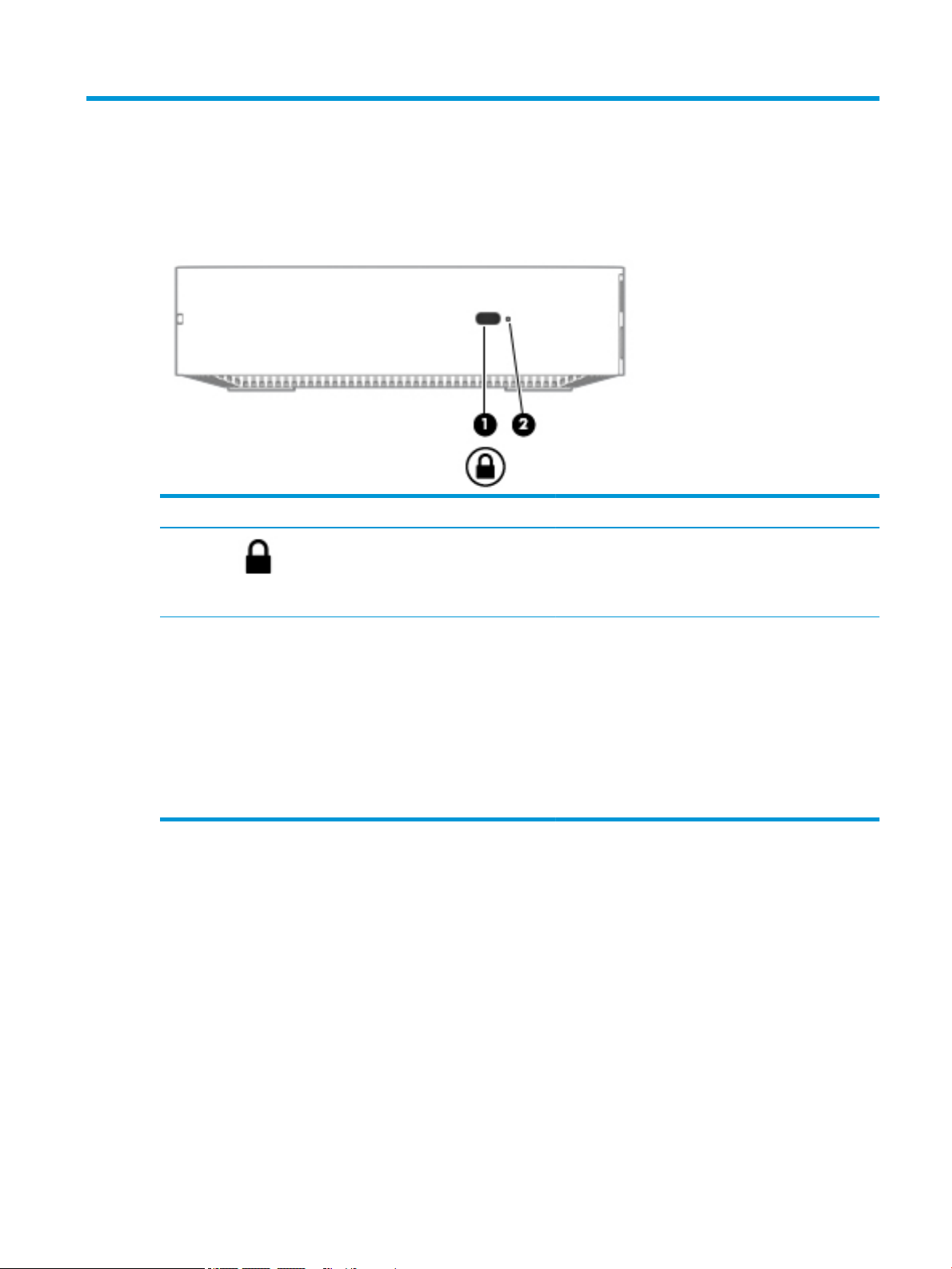
Right side
Component Description
(1) Security cable slot Attaches an optional security cable to the computer.
NOTE: The security cable is designed to act as a
deterrent, but it may not prevent the computer from being
mishandled or stolen.
(2) Reset/recovery button To to reset or recover the device, insert a paperclip (or
pushpin) into the reset/recovery button hole, and then
press the button.
NOTE: Using this button in conjunction with the Power
button will result in all account information and data
stored on your Chromebox, such as photos, downloaded
les, and saved networks, being deleted. Saving les to a
external hard drive, USB ash drive, or cloud storage is
recommended for this reason. You may save your les to
the cloud at any time by selecting the Google Drive as your
le save location.
Right side 3
Page 10
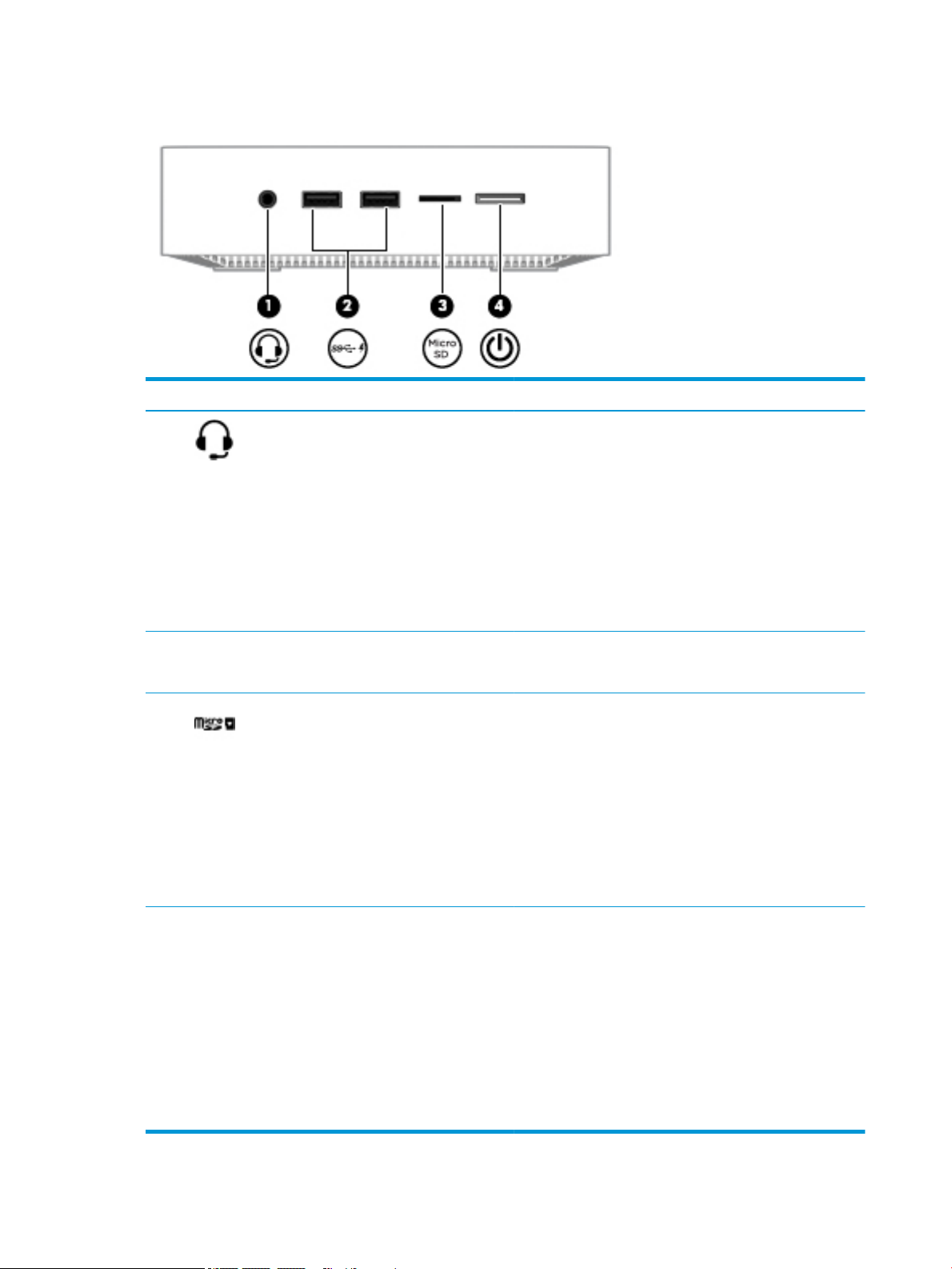
Front
Component Description
(1) Audio-out (headphone)/Audio-in (microphone)
combo jack
(2) USB SuperSpeed ports with HP Sleep and
Charge (2)
(3) MicroSD memory card reader Reads optional memory cards that store, manage, share, or
Connects optional powered stereo speakers, headphones,
earbuds, a headset, or a television audio cable. Also connects an
optional headset microphone. This jack does not support
optional microphone-only devices.
WARNING! To reduce the risk of personal injury, adjust the
volume before putting on headphones, earbuds, or a headset.
For additional safety information, refer to the Regulatory,
Safety, and Environmental Notices.
This guide is provided in the box.
NOTE: When a device is connected to the jack, the computer
speakers are disabled.
Connects a USB device, provides high-speed data transfer, and
even when the computer is o, charges most products such as a
cell phone, camera, activity tracker, or smartwatch.
access information.
To insert a card:
1. Hold the card label-side up, with connectors facing the
computer.
2. Insert the card into the memory card reader, and then
press in on the card until it is rmly seated.
To remove a card:
▲ Pull out the card.
(4) Power button/Power light
4 Chapter 2 Getting to know your Chromebox
●
When the Chromebox is o, press the button to turn on the
device. A white light indicates that the unit is on. The light
will be o if the unit is o or in standby mode.
●
When the device is in the Sleep state, press the button
briey to exit Sleep.
●
When the device is on and you want to lock the screen,
press the power button until you see the sign-in screen
appear. Pressing the power button during screen-lock
mode turns o the device.
●
When the device is on and you want to turn it o, press and
hold the power button.
Page 11
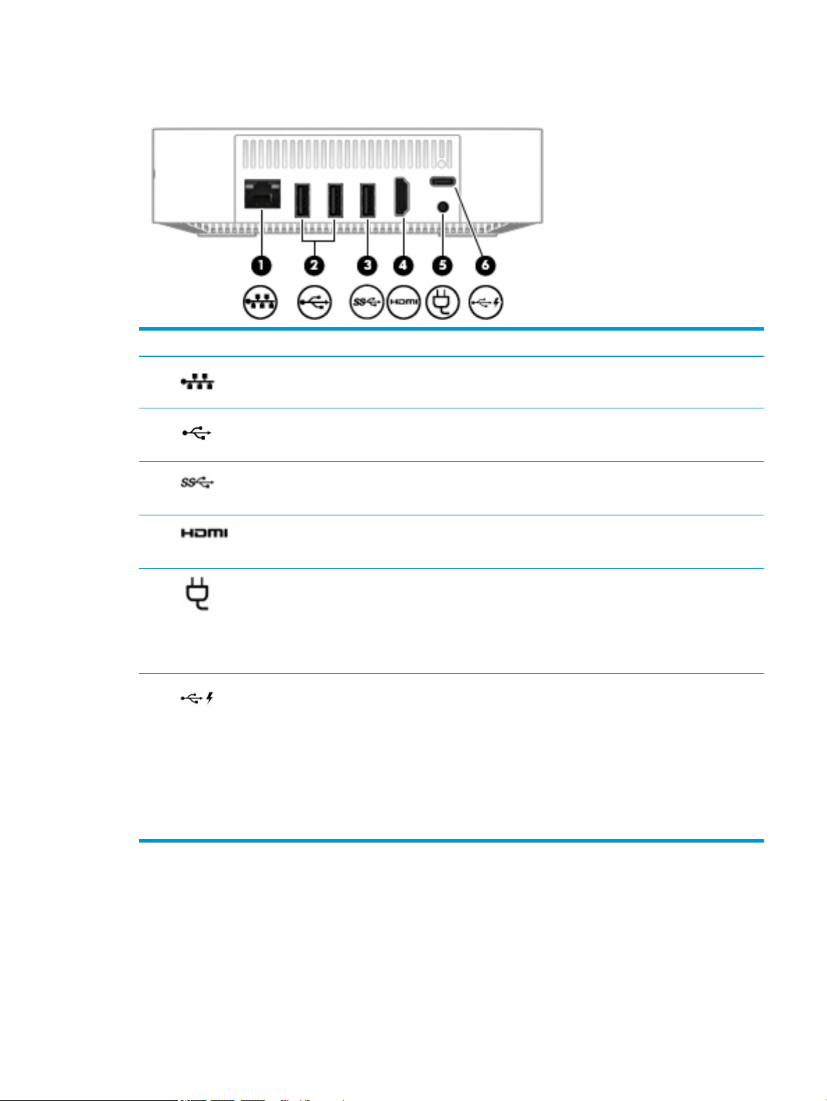
Rear
Component Description
(1) RJ-45 (network) jack Connects a network cable.
(2) USB port Connects a USB device, such as a cell phone,
camera, activity tracker, or smartwatch, and
provides data transfer.
(3) USB SuperSpeed ports (2) Connect a USB device, such as a cell phone, camera,
activity tracker, or smartwatch, and provides highspeed data transfer.
(4) HDMI port Connects an optional video or audio device, such as
a high-denition television, or any compatible
digital or audio device.
(5) Power connector Connects an AC adapter.
NOTE: Your device will attempt to preserve your
work in the event of a power event. If you
experience a power outage, or accidentally unplug
your device, your Chromebox will automatically
restart when power is restored.
(6) USB Type-C port with HP Sleep and
Charge
Connects a USB device that has a Type-C connector,
provides data transfer, and even when the
computer is o, charges most products such as a
cell phone, camera, activity tracker, or smartwatch.
– and –
Connects a display device that has a USB Type-C
connector, providing DisplayPort output.
NOTE: Cables and/or adapters (purchased
separately) may be required.
Rear 5
Page 12

Bottom
Component Description
Vent Enables airow to cool internal components.
NOTE: The device fan starts up automatically to cool internal
components and prevent overheating. It is normal for the
internal fan to cycle on and o during routine operation.
6 Chapter 2 Getting to know your Chromebox
Page 13
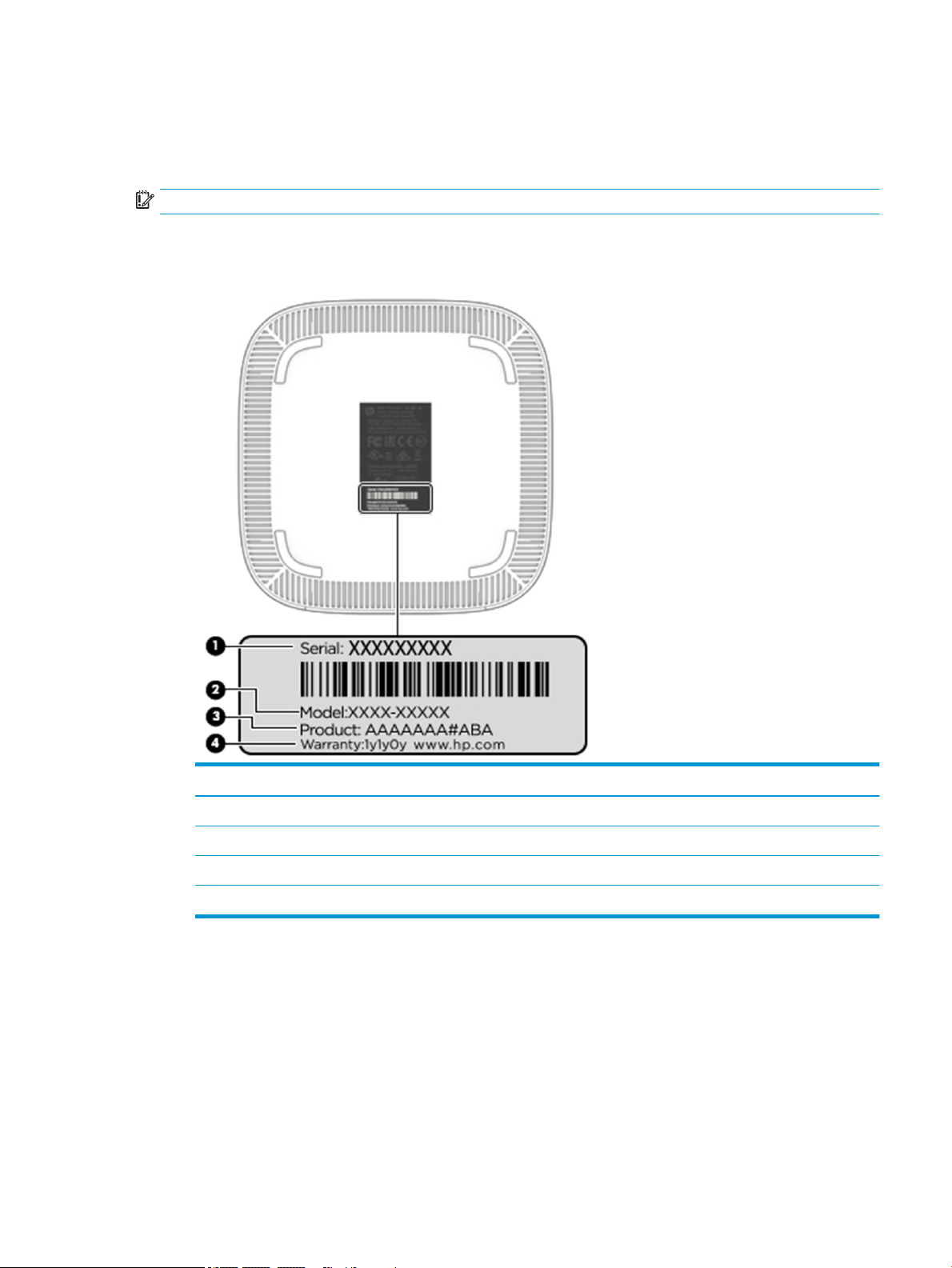
Labels
The labels axed to the computer provide information you may need when you troubleshoot system
problems or travel internationally with the computer.
IMPORTANT: All labels described in this section will be axed to the bottom of the computer.
●
Service label—Provides important information to identify your computer. When contacting support, you
will probably be asked for the serial number, and possibly for the product number or the model number.
Locate these numbers before you contact support.
Component
(1) Serial number
(2) Model number (select products only)
(3) Product number
(4) Warranty period
●
Regulatory label(s)—Provide(s) regulatory information about the computer.
●
Wireless certication label(s)—Provide(s) information about optional wireless devices and the approval
markings for the countries or regions in which the devices have been approved for use.
Labels 7
Page 14
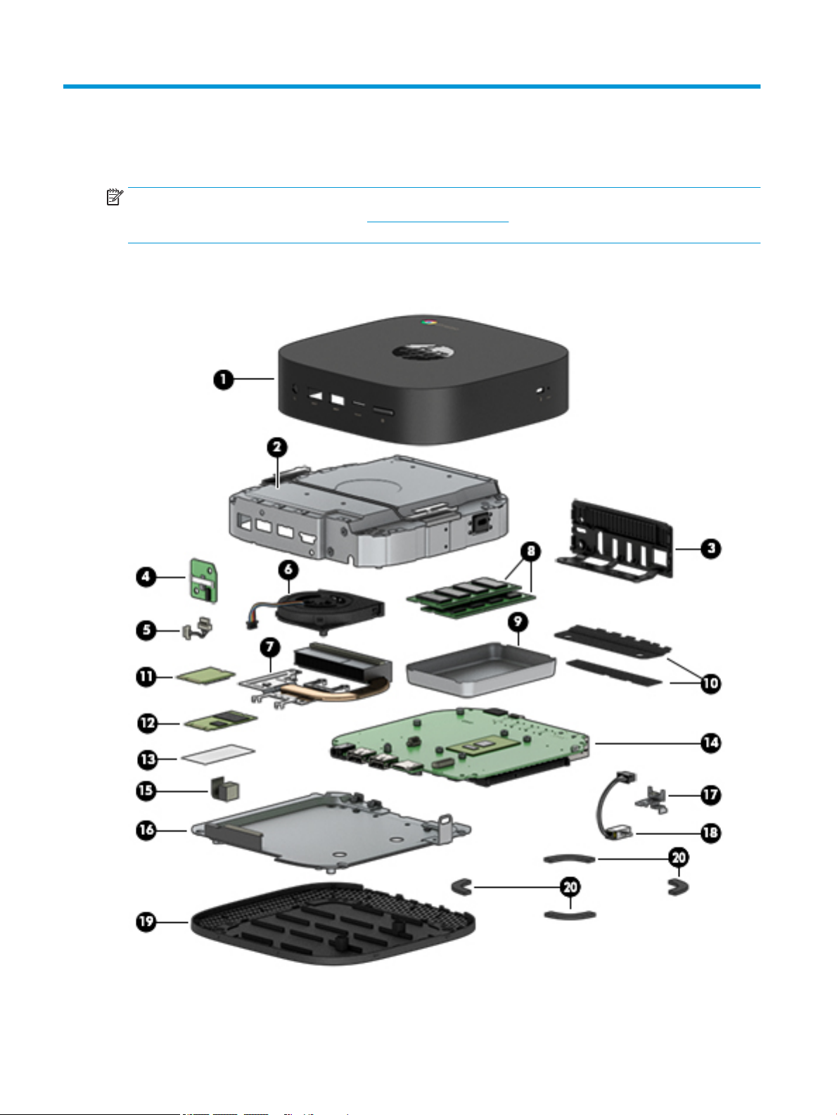
3 Illustrated parts catalog
NOTE: HP continually improves and changes product parts. For complete and current information on
supported parts for your computer, go to http://partsurfer.hp.com, select your country or region, and then
follow the on-screen instructions.
Computer major components
8 Chapter 3 Illustrated parts catalog
Page 15

Item Component Spare part number
(1) Top cover L17257-001
(2) Metal top shield (includes antenna) L17268-001
(3) Rear I/O bracket L17262-001
(4) Power button board L17270-001
(5) Power button board cable L17260-001
(6) Fan 767360-001
(7) Heat sink (includes replacement thermal material) L17261-001
(8) Memory modules (SODIMM, DDR4-2400 MHz)
8 GB 862398-850
4 GB 862397-850
(9) Memory cover L17264-001
(10) Mylar Kit (for use when replacing bottom cover) L20217-001
(11) Intel Dual Band Wireless-AC 7265 802.11 AC 2×2 WiFi + Bluetooth 4.2 Combo Adapter
(non-vPro) WLAN module
(12) Solid-state drive (M.2, SATA-3)
64 GB L17274-001
32 GB L17273-001
(13) Solid-state drive absorber L17263-001
(14) System board (includes processor and replacement thermal material):
Equipped with an Intel Core i7-8650U processor L17277-001
Equipped with an Intel Core i5-7300 processor L17276-001
Equipped with an Intel Celeron 3865U processor L17275-001
(15) HDMI gasket L17846-001
(16) Bottom shield L17267-001
(17) Power connector bracket
NOTE: Power connector conductive tape is available using spare part number
L17265-001.
(18) Power connector cable L17259-001
(19) Bottom cover L17258-001
860883-001
L17266-001
(20) Rubber feet L17271-001
Computer major components 9
Page 16

Miscellaneous parts
Component Spare part number
AC adapter:
65-W AC adapter (non-PFC, S-3P, 4.5-mm) 710412-001
65-W AC adapter, EM (non-PFC, 4.5-mm) 913691-850
90-W AC adapter (PFC, 4.5-mm) 710413-001
Power cord (C5 connector, 1.0-m):
For use in Argentina L19357-001
For use in Australia L19358-001
For use in Denmark L19360-001
For use in Europe L19361-001
For use in India L19363-001
For use in Israel L19362-001
For use in Italy L19364-001
For use in Japan L19365-001
For use in North America L19367-001
For use in the People’s Republic of China L19368-001
For use in South Africa L19369-001
For use in South Korea L19366-001
For use in Switzerland L19370-001
For use in Taiwan L19372-001
For use in Thailand L19371-001
For use in the United Kingdom and Singapore L19373-001
Screw Kit L17272-001
10 Chapter 3 Illustrated parts catalog
Page 17

Whole unit spares
Component Spare part number
Whole unit, 3SX33AA ABA L26674-001
Whole unit, 3SX34AA ABA L26675-001
Whole unit, 3SX35AA ABA L26676-001
Whole unit, 3SX33AA ABU L29219-001
Whole unit, 3SX34AA ABU L29220-001
Whole unit, 3SX35AA ABU L29221-001
Whole unit, 3SX33AA UUF L29222-001
Whole unit, 3SX34AA UUF L29223-001
Whole unit, 3SX35AA UUF L29224-001
Whole unit spares 11
Page 18

4 Removal and replacement preliminary
requirements
Tools required
You will need the following tools to complete the removal and replacement procedures:
●
Flat-bladed screw driver
●
Magnetic screw driver
●
Phillips P0 screw driver
Service considerations
The following sections include some of the considerations that you must keep in mind during disassembly
and assembly procedures.
NOTE: As you remove each subassembly from the computer, place the subassembly (and all
accompanying screws) away from the work area to prevent damage.
Plastic parts
CAUTION: Using excessive force during disassembly and reassembly can damage plastic parts. Use care
when handling the plastic parts. Apply pressure only at the points designated in
the maintenance instructions.
Cables and connectors
CAUTION: When servicing the computer, be sure that cables are placed in their proper locations during
the reassembly process. Improper cable placement can damage the computer.
Cables must be handled with extreme care to avoid damage. Apply only the tension required to unseat or seat
the cables during removal and insertion. Handle cables by the connector whenever possible. In all cases, avoid
bending, twisting, or tearing cables. Be sure that cables are routed in such a way that they cannot be caught
or snagged by parts being removed or replaced. Handle ex cables with extreme care; these cables
tear easily.
12 Chapter 4 Removal and replacement preliminary requirements
Page 19

Drive handling
CAUTION: Drives are fragile components that must be handled with care. To prevent damage to
the computer, damage to a drive, or loss of information, observe these precautions:
Before removing or inserting a drive, shut down the computer. If you are unsure whether the computer is o
or in Hibernation, turn the computer on, and then shut it down through the operating system.
Before handling a drive, be sure that you are discharged of static electricity. While handling a drive, avoid
touching the connector.
Before removing a diskette drive or optical drive, be sure that a diskette or disc is not in the drive and be sure
that the optical drive tray is closed.
Handle drives on surfaces covered with at least one inch of shock-proof foam.
Avoid dropping drives from any height onto any surface.
After removing drive, place it in a static-proof bag.
Avoid exposing a drive to products that have magnetic elds, such as monitors or speakers.
Avoid exposing a drive to temperature extremes or liquids.
If a drive must be mailed, place the drive in a bubble pack mailer or other suitable form of protective
packaging and label the package “FRAGILE.”
Service considerations 13
Page 20

Grounding guidelines
Electrostatic discharge damage
Electronic components are sensitive to electrostatic discharge (ESD). Circuitry design and structure determine
the degree of sensitivity. Networks built into many integrated circuits provide some protection, but in many
cases, ESD contains enough power to alter device parameters or melt silicon junctions.
A discharge of static electricity from a nger or other conductor can destroy static-sensitive devices or
microcircuitry. Even if the spark is neither felt nor heard, damage may have occurred.
An electronic device exposed to ESD may not be aected at all and can work perfectly throughout a normal
cycle. Or the device may function normally for a while, then degrade in the internal layers, reducing its
life expectancy.
CAUTION: To prevent damage to the computer when you are removing or installing internal components,
observe these precautions:
Keep components in their electrostatic-safe containers until you are ready to install them.
Before touching an electronic component, discharge static electricity by using the guidelines described in
this section.
Avoid touching pins, leads, and circuitry. Handle electronic components as little as possible.
If you remove a component, place it in an electrostatic-safe container.
The following table shows how humidity aects the electrostatic voltage levels generated by
dierent activities.
CAUTION: A product can be degraded by as little as 700 V.
Typical electrostatic voltage levels
Relative humidity
Event 10% 40% 55%
Walking across carpet 35,000 V 15,000 V 7,500 V
Walking across vinyl oor 12,000 V 5,000 V 3,000 V
Motions of bench worker 6,000 V 800 V 400 V
Removing DIPS from plastic tube 2,000 V 700 V 400 V
Removing DIPS from vinyl tray 11,500 V 4,000 V 2,000 V
Removing DIPS from Styrofoam 14,500 V 5,000 V 3,500 V
Removing bubble pack from PCB 26,500 V 20,000 V 7,000 V
Packing PCBs in foam-lined box 21,000 V 11,000 V 5,000 V
14 Chapter 4 Removal and replacement preliminary requirements
Page 21

Packaging and transporting guidelines
Follow these grounding guidelines when packaging and transporting equipment:
●
To avoid hand contact, transport products in static-safe tubes, bags, or boxes.
●
Protect ESD-sensitive parts and assemblies with conductive or approved containers or packaging.
●
Keep ESD-sensitive parts in their containers until the parts arrive at static-free workstations.
●
Place items on a grounded surface before removing items from their containers.
●
Always be properly grounded when touching a component or assembly.
●
Store reusable ESD-sensitive parts from assemblies in protective packaging or nonconductive foam.
●
Use transporters and conveyors made of antistatic belts and roller bushings. Be sure that mechanized
equipment used for moving materials is wired to ground and that proper materials are selected to avoid
static charging. When grounding is not possible, use an ionizer to dissipate electric charges.
Workstation guidelines
Follow these grounding workstation guidelines:
●
Cover the workstation with approved static-shielding material.
●
Use a wrist strap connected to a properly grounded work surface and use properly grounded tools
and equipment.
●
Use conductive eld service tools, such as cutters, screw drivers, and vacuums.
●
When xtures must directly contact dissipative surfaces, use xtures made only of static-safe materials.
●
Keep the work area free of nonconductive materials, such as ordinary plastic assembly aids
and Styrofoam.
●
Handle ESD-sensitive components, parts, and assemblies by the case or PCM laminate. Handle these
items only at static-free workstations.
●
Avoid contact with pins, leads, or circuitry.
●
Turn o power and input signals before inserting or removing connectors or test equipment.
Grounding guidelines 15
Page 22

Equipment guidelines
Grounding equipment must include either a wrist strap or a foot strap at a grounded workstation.
●
When seated, wear a wrist strap connected to a grounded system. Wrist straps are exible straps with a
minimum of one megohm ±10% resistance in the ground cords. To provide proper ground, wear a strap
snugly against the skin at all times. On grounded mats with banana-plug connectors, use alligator clips
to connect a wrist strap.
●
When standing, use foot straps and a grounded oor mat. Foot straps (heel, toe, or boot straps) can be
used at standing workstations and are compatible with most types of shoes or boots. On conductive
oors or dissipative oor mats, use foot straps on both feet with a minimum of one megohm resistance
between the operator and ground. To be eective, the conductive must be worn in contact with the skin.
The following grounding equipment is recommended to prevent electrostatic damage:
●
Antistatic tape
●
Antistatic smocks, aprons, and sleeve protectors
●
Conductive bins and other assembly or soldering aids
●
Nonconductive foam
●
Conductive computerop workstations with ground cords of one megohm resistance
●
Static-dissipative tables or oor mats with hard ties to the ground
●
Field service kits
●
Static awareness labels
●
Material-handling packages
●
Nonconductive plastic bags, tubes, or boxes
●
Metal tote boxes
●
Electrostatic voltage levels and protective materials
The following table lists the shielding protection provided by antistatic bags and oor mats.
Material Use Voltage protection level
Antistatic plastics Bags 1,500 V
Carbon-loaded plastic Floor mats 7,500 V
Metallized laminate Floor mats 5,000 V
16 Chapter 4 Removal and replacement preliminary requirements
Page 23

5 Removal and replacement procedures
This chapter provides removal and replacement procedures for Authorized Service Provider only parts.
CAUTION: Components described in this chapter should only be accessed by an authorized service provider.
Accessing these parts can damage the computer or void the warranty.
CAUTION: This computer does not have user-replaceable parts. Only HP authorized service providers should
perform the removal and replacement procedures described here. Accessing the internal part could damage
the computer or void the warranty.
Component replacement procedures
NOTE: Details about your computer, including model, serial number, product key, and length of warranty,
are on the service tag at the bottom of your computer. See Labels on page 7 for details.
NOTE: HP continually improves and changes product parts. For complete and current information on
supported parts for your computer, go to http://partsurfer.hp.com, select your country or region, and then
follow the on-screen instructions.
There are as many as 31 screws that must be removed, replaced, and/or loosened when servicing Authorized
Service Provider only parts. Make special note of each screw size and location during removal
and replacement.
Bottom cover
Description Spare part number
Bottom cover L17258-001
Rubber feet L17271-001
Mylar kit L20217-001
Before removing the bottom cover, follow these steps:
1. Shut down the computer. If you are unsure whether the computer is o or in Hibernation, turn
the computer on, and then shut it down through the operating system.
2. Disconnect all external devices connected to the computer.
3. Disconnect the power from the computer by rst unplugging the power cord from the AC outlet, and
then unplugging the AC adapter from the computer.
Remove the bottom cover:
1. Position the computer upside down on a at surface.
2. Peel the four rubber feet o the bottom cover (1).
Component replacement procedures 17
Page 24

3. Remove the four Phillips M2.5×4.0 screws (2) that secure the bottom cover to the computer.
4. Insert a at, non-marking tool into the gap under the bottom cover near the USB ports on the rear of the
computer (1), and then pry the bottom cover o the computer (2).
Reverse this procedure to install the bottom cover.
18 Chapter 5 Removal and replacement procedures
Page 25

When replacing the bottom cover, be sure to install two pieces of Mylar onto the chassis as shown in the
following image. A Mylar Kit is available using spare part number L20217-001.
Component replacement procedures 19
Page 26

Rear I/O bracket
Description Spare part number
Rear I/O bracket L17262-001
Before removing the rear I/O bracket, follow these steps:
1. Shut down the computer. If you are unsure whether the computer is o or in Hibernation, turn
the computer on, and then shut it down through the operating system.
2. Disconnect all external devices connected to the computer.
3. Disconnect the power from the computer by rst unplugging the power cord from the AC outlet, and
then unplugging the AC adapter from the computer.
4. Remove the bottom cover (see Bottom cover on page 17).
Remove the rear I/O bracket:
1. Lift the Mylar tape from on top of the bracket (1).
2. Remove the two Phillips M2.5×4.0 screws (2) that secure the bracket to the computer.
3. Rotate the top of the bracket o the chassis (3), and then remove the bracket (4).
Reverse this procedure to install the rear I/O bracket.
20 Chapter 5 Removal and replacement procedures
Page 27

Bottom shield
Description Spare part number
Bottom shield L17267-001
Before removing the bottom shield, follow these steps:
1. Shut down the computer. If you are unsure whether the computer is o or in Hibernation, turn
the computer on, and then shut it down through the operating system.
2. Disconnect all external devices connected to the computer.
3. Disconnect the power from the computer by rst unplugging the power cord from the AC outlet, and
then unplugging the AC adapter from the computer.
4. Remove the bottom cover (see Bottom cover on page 17).
5. Remove the rear I/O bracket (see Rear I/O bracket on page 20).
Remove the bottom shield:
1. Lift the tape from on top of the bottom shield (1).
2. Remove the four Phillips M2.5×4.0 screws (2) that secure the shield to the computer.
IMPORTANT: A cable connects from the system board to the bottom shield. Be sure not to accidentally
disconnect this cable when removing the bottom shield.
3. Lift and rotate the bottom shield to gain access to the cable underneath (1).
Component replacement procedures 21
Page 28

4. Disconnect the cable from the system board (2).
Reverse this procedure to install the bottom shield.
22 Chapter 5 Removal and replacement procedures
Page 29

Power connector cable
The power connector cable is installed on the bottom shield.
Description Spare part number
Power connector cable L17259-001
Power connector bracket L17266-001
Power connector conductive tape L17265-001
Before removing the power connector cable, follow these steps:
1. Shut down the computer. If you are unsure whether the computer is o or in Hibernation, turn
the computer on, and then shut it down through the operating system.
2. Disconnect all external devices connected to the computer.
3. Disconnect the power from the computer by rst unplugging the power cord from the AC outlet, and
then unplugging the AC adapter from the computer.
4. Remove the bottom cover (see Bottom cover on page 17).
5. Remove the rear I/O bracket (see Rear I/O bracket on page 20).
6. Remove the bottom shield (see Bottom shield on page 21).
Remove the power connector cable:
1. Position the bottom shield upside-down.
2. Remove the two Phillips M2.5×4.0 screws (1) that secure the power connector cable to the bottom
shield.
3. Remove the bracket (2).
Component replacement procedures 23
Page 30

4. Remove the power connector cable (3) from the bottom shield.
NOTE: When replacing the power connector cable, be sure to install conductive tape (4) on top of the
bracket. Conductive tape is available using spare part number L17265-001.
Reverse this procedure to install the power connector cable.
24 Chapter 5 Removal and replacement procedures
Page 31

WLAN module
Description Spare part number
Intel Dual Band Wireless-AC 7265 802.11 AC 2×2 WiFi + Bluetooth 4.2 Combo Adapter (non-vPro) 860883-001
CAUTION: To prevent an unresponsive system, replace the wireless module only with a wireless module
authorized for use in the computer by the governmental agency that regulates wireless devices in your
country or region. If you replace the module and then receive a warning message, remove the module to
restore device functionality, and then contact technical support.
Before removing the WLAN module, follow these steps:
1. Turn o the computer. If you are unsure whether the computer is o or in Hibernation, turn
the computer on, and then shut it down through the operating system.
2. Disconnect the power from the computer by rst unplugging the power cord from the AC outlet, and
then unplugging the AC adapter from the computer.
3. Disconnect all external devices from the computer.
4. Remove the bottom cover (see Bottom cover on page 17).
5. Remove the rear I/O bracket (see Rear I/O bracket on page 20).
6. Remove the bottom shield (see Bottom shield on page 21).
Remove the WLAN module:
1. Disconnect the WLAN antenna cables (1) from the terminals on the WLAN module.
NOTE: The WLAN antenna cable labeled "1/MAIN" connects to the WLAN module "Main" terminal. The
WLAN antenna cable labeled "2/AUX" connects to the WLAN module "Aux" terminal.
2. Remove the Phillips M2.0×3.0 screw (2) that secures the WLAN module to the computer.
(The WLAN module tilts up.)
Component replacement procedures 25
Page 32

3. Remove the WLAN module (3) by pulling the module away from the slot at an angle.
NOTE: WLAN modules are designed with a notch to prevent incorrect insertion.
Reverse this procedure to install the WLAN module.
26 Chapter 5 Removal and replacement procedures
Page 33

Memory module
NOTE: The memory module spare part kit does not include the memory cover. The memory cover is
available using spare part number L17264-001.
NOTE: Primary and expansion memory is installed in a stacked conguration. If only one memory module is
installed, it must be installed in the bottom socket.
Description Spare part number
8-MB, DDR4-2400, 1.2-V 862398-850
4-MB, DDR4-2400, 1.2-V 862397-850
Memory cover L17264-001
Before removing the memory module, follow these steps:
1. Turn o the computer. If you are unsure whether the computer is o or in Hibernation, turn
the computer on, and then shut it down through the operating system.
2. Disconnect the power from the computer by rst unplugging the power cord from the AC outlet, and
then unplugging the AC adapter from the computer.
3. Disconnect all external devices from the computer.
4. Remove the bottom cover (see Bottom cover on page 17).
5. Remove the rear I/O bracket (see Rear I/O bracket on page 20).
6. Remove the bottom shield (see Bottom shield on page 21).
Remove the memory module cover and memory modules:
1. Squeeze the sides of the memory cover (1), and then lift the cover o the system board (2).
Component replacement procedures 27
Page 34

2. Spread the two retention clips outward (1) until the memory module tilts up at a 45-degree angle.
3. Grasp the edge of the memory module (2), and then gently pull the module out of the slot. Use the same
procedure to remove both memory modules.
NOTE: To prevent damage to the memory module, hold the memory module by the edges only. Do not
touch the components on the memory module.
To protect a memory module after removal, place it in an electrostatic-safe container.
Reverse this procedure to install the memory modules and memory cover.
To replace the memory cover, align the bottom edges of the cover with the small clips on the system board
(1), and then insert the cover into the clips (2).
28 Chapter 5 Removal and replacement procedures
Page 35

Component replacement procedures 29
Page 36

Solid-state drive
Description Spare part number
Solid-state drive, 64 GB L17274-001
Solid-state drive, 32 GB L17273-001
Solid-state drive absorber L17263-001
Before removing the solid-state drive, follow these steps:
1. Shut down the computer. If you are unsure whether the computer is o or in Hibernation, turn
the computer on, and then shut it down through the operating system.
2. Disconnect all external devices connected to the computer.
3. Disconnect the power from the computer by rst unplugging the power cord from the AC outlet, and
then unplugging the AC adapter from the computer.
4. Remove the bottom cover (see Bottom cover on page 17).
5. Remove the rear I/O bracket (see Rear I/O bracket on page 20).
6. Remove the bottom shield (see Bottom shield on page 21).
7. Remove the WLAN module (see WLAN module on page 25).
Remove the solid-state drive:
1. Lift the solid-state drive absorber o the connector and drive module (1).
NOTE: The solid-state drive absorber is available using spare part number L17263-001.
2. Remove the Phillips M2.0×3.0 screw (2), and then pull the solid-state drive module from the socket (3).
Reverse this procedure to install a solid-state drive.
30 Chapter 5 Removal and replacement procedures
Page 37

System board
NOTE: All system board spare part kits include a processor and replacement thermal material.
Description Spare part number
System board with integrated Intel Core i7-8650U processor L17277-001
System board with integrated Intel Core i5-7300 processor L17276-001
System board with integrated Intel Celeron 3865U processor L17275-001
HDMI gasket L17846-001
Before removing the system board, follow these steps:
1. Shut down the computer. If you are unsure whether the computer is o or in Hibernation, turn
the computer on, and then shut it down through the operating system.
2. Disconnect all external devices connected to the computer.
3. Disconnect the power from the computer by rst unplugging the power cord from the AC outlet, and
then unplugging the AC adapter from the computer.
4. Remove the bottom cover (see Bottom cover on page 17).
5. Remove the rear I/O bracket (see Rear I/O bracket on page 20).
6. Remove the bottom shield (see Bottom shield on page 21).
When replacing the system board, be sure to remove the following components (as applicable) from the
defective system board and install them on the replacement system board:
●
WLAN module (see WLAN module on page 25)
●
Memory modules (see Memory module on page 27)
●
Fan (see Fan on page 33)
●
Heat sink (see Heat sink on page 34)
Remove the system board:
1. Disconnect the power button board cable from the system board (1).
2. Remove the three larger Phillips M2.5×4.0 screws (2) and the smaller Phillips M2.0×2.0 screw (3) that
secures the system board to the computer.
Component replacement procedures 31
Page 38

3. Lift the system board out of the computer (4).
Reverse this procedure to install the system board.
When installing the system board, be sure the HDMI gasket is installed over the HDMI port as shown in the
following illustration. The HDMI gasket is available using spare part number L17846-001.
32 Chapter 5 Removal and replacement procedures
Page 39

Fan
The fan is installed on the bottom of the system board.
Description Spare part number
Fan 767360-001
Before removing the fan, follow these steps:
1. Shut down the computer. If you are unsure whether the computer is o or in Hibernation, turn
the computer on, and then shut it down through the operating system.
2. Disconnect all external devices connected to the computer.
3. Disconnect the power from the computer by rst unplugging the power cord from the AC outlet, and
then unplugging the AC adapter from the computer.
4. Remove the bottom cover (see Bottom cover on page 17).
5. Remove the rear I/O bracket (see Rear I/O bracket on page 20).
6. Remove the bottom shield (see Bottom shield on page 21).
7. Remove the system board (see System board on page 31).
Remove the fan:
1. Position the system board upside-down.
2. Disconnect the fan cable from the system board (1).
3. Remove the two Phillips M2.5×4.0 screws (2) that secure the fan to the system board.
4. Remove the fan from the system board (3).
Reverse this procedure to install the fan.
Component replacement procedures 33
Page 40

Heat sink
The heat sink is installed on the bottom of the system board.
Before removing the heat sink, follow these steps:
1. Turn o the computer. If you are unsure whether the computer is o or in Hibernation, turn
2. Disconnect the power from the computer by rst unplugging the power cord from the AC outlet, and
3. Disconnect all external devices from the computer.
4. Remove the bottom cover (see Bottom cover on page 17).
5. Remove the rear I/O bracket (see Rear I/O bracket on page 20).
6. Remove the bottom shield (see Bottom shield on page 21).
7. Remove the system board (see System board on page 31).
8. Remove the fan (see Fan on page 33).
Description Spare part number
Heat sink (includes replacement thermal material) L17261-001
the computer on, and then shut it down through the operating system.
then unplugging the AC adapter from the computer.
Remove the heat sink:
1. Position the system board upside-down.
2. In the order shown, remove the four Phillips M2.0×3.0 screws (1)-(4) that secure the heat sink to the
system board.
3. Remove the heat sink from the system board (5).
34 Chapter 5 Removal and replacement procedures
Page 41

NOTE: The thermal material must be thoroughly cleaned from the surfaces of the heat sink and the system
board components each time the heat sink is removed. Replacement thermal material is included with the
heat sink and system board spare part kits.
Thermal paste is used on the processor (1) and the heat sink section (2) that services it.
Reverse this procedure to install the heat sink.
Component replacement procedures 35
Page 42

Top cover (plastic) and metal top shield
Description Spare part number
Top cover (plastic) L17257-001
Metal top shield (includes antenna) L17268-001
Before removing the top cover, follow these steps:
1. Shut down the computer. If you are unsure whether the computer is o or in Hibernation, turn
the computer on, and then shut it down through the operating system.
2. Disconnect all external devices connected to the computer.
3. Disconnect the power from the computer by rst unplugging the power cord from the AC outlet, and
then unplugging the AC adapter from the computer.
4. Remove the bottom cover (see Bottom cover on page 17).
5. Remove the rear I/O bracket (see Rear I/O bracket on page 20).
6. Remove the bottom shield (see Bottom shield on page 21).
7. Remove the system board (see System board on page 31).
Remove the top cover:
1. Remove the Phillips M2.5×4.0 screw (1) from the small metal bracket, and the remove the bracket from
the metal top shield (2).
2. Remove the four Phillips M2.5×4.0 screws (3) that secure the plastic top cover to the metal top shield.
36 Chapter 5 Removal and replacement procedures
Page 43

3. Separate the metal top shield from the plastic top cover (4).
Reverse this procedure to reassembly the top cover and top shield.
Component replacement procedures 37
Page 44

Power button board
The power button board is installed onto the metal top shield.
Description Spare part number
Power button board (does not include cable) L17270-001
Power button board cable L17260-001
Before removing the power button board, follow these steps:
1. Shut down the computer. If you are unsure whether the computer is o or in Hibernation, turn
the computer on, and then shut it down through the operating system.
2. Disconnect all external devices connected to the computer.
3. Disconnect the power from the computer by rst unplugging the power cord from the AC outlet, and
then unplugging the AC adapter from the computer.
4. Remove the bottom cover (see Bottom cover on page 17).
5. Remove the rear I/O bracket (see Rear I/O bracket on page 20).
6. Remove the bottom shield (see Bottom shield on page 21).
7. Remove the system board (see System board on page 31).
8. Separate the plastic top cover from the metal top shield (see Top cover (plastic) and metal top shield
on page 36).
Remove the power button board:
1. Position the metal top shield with the power button board facing you.
2. Remove the two Phillips M2.0×3.0 screws (1) that secure the board to the metal top shield.
38 Chapter 5 Removal and replacement procedures
Page 45

3. Lift the board from the metal top shield (2), and then disconnect the cable from the power button board
(3).
Reverse this procedure to install the power button board.
Component replacement procedures 39
Page 46

6 Specications
Metric U.S.
Computer dimensions
Width 149.3 mm 5.87 in
Depth 149.3 mm 5.87 in
Height 40 mm 1.57 in
Weight 0.57 kg 1.26 lbs
Temperature
Operating 5°C to 35°C 41°F to 95°F
Nonoperating ‑20°C to 60°C ‑4°F to 140°F
Relative humidity (noncondensing)
Operating 10% to 90%
Nonoperating 5% to 95%
Maximum altitude (unpressurized)
Operating ‑15 m to 3,048 m ‑50 ft to 10,000 ft
Nonoperating ‑15 m to 12,192 m ‑50 ft to 40,000 ft
NOTE: Applicable product safety standards specify thermal limits for plastic surfaces. The device operates well within this range of
temperatures.
40 Chapter 6 Specications
Page 47

7 Power cord set requirements
The wide-range input feature of the computer permits it to operate from any line voltage from 100 to 120
volts AC, or from 220 to 240 volts AC.
The 3-conductor power cord set included with the computer meets the requirements for use in the country or
region where the equipment is purchased.
Power cord sets for use in other countries and regions must meet the requirements of the country or region
where the computer is used.
Requirements for all countries
The following requirements are applicable to all countries and regions:
●
The length of the power cord set must be at least 1.0 m (3.3 ft) and no more than 2.0 m (6.5 ft).
●
All power cord sets must be approved by an acceptable accredited agency responsible for evaluation in
the country or region where the power cord set will be used.
●
The power cord sets must have a minimum current capacity of 10 amps and a nominal voltage rating of
125 or 250 V AC, as required by the power system of each country or region.
●
The appliance coupler must meet the mechanical conguration of an EN 60 320/IEC 320 Standard Sheet
C13 connector for mating with the appliance inlet on the back of the computer. Requirements for all
countries 113
Requirements for specic countries and regions
Country/region Accredited agency Applicable note number
Australia EANSW 1
Austria OVE 1
Belgium CEBC 1
Canada CSA 2
Denmark DEMKO 1
Finland FIMKO 1
France UTE 1
Germany VDE 1
Italy IMQ 1
Japan METI 3
The Netherlands KEMA 1
Norway NEMKO 1
The People's Republic of China COC 5
Requirements for all countries 41
Page 48

Country/region Accredited agency Applicable note number
South Korea EK 4
Sweden CEMKO 1
Switzerland SEV 1
Taiwan BSMI 4
The United Kingdom BSI 1
The United States UL 2
1. The exible cord must be Type HO5VV-F, 3-conductor, 1.0-mm² conductor size. Power cord set ttings (appliance coupler and
wall plug) must bear the certication mark of the agency responsible for evaluation in the country or region where it will be used.
2. The exible cord must be Type SPT-3 or equivalent, No. 18 AWG, 3-conductor. The wall plug must be a two-pole grounding type
with a NEMA 5-15P (15 A, 125 V) or NEMA 6-15P (15 A, 250 V) conguration.
3. The appliance coupler, exible cord, and wall plug must bear a “T” mark and registration number in accordance with the Japanese
Dentori Law. The exible cord must be Type VCT or VCTF, 3-conductor, 1.00-mm² conductor size. The wall plug must be a twopole grounding type with a Japanese Industrial Standard C8303 (7 A, 125 V) conguration.
4. The exible cord must be Type RVV, 3-conductor, 0.75-mm² conductor size. Power cord set ttings (appliance coupler and wall
plug) must bear the certication mark of the agency responsible for evaluation in the country or region where it will be used.
5. The exible cord must be Type VCTF, 3-conductor, 0.75-mm² conductor size. Power cord set ttings (appliance coupler and wall
plug) must bear the certication mark of the agency responsible for evaluation in the country or region where it will be used.
42 Chapter 7 Power cord set requirements
Page 49

8 Recycling
When a non-rechargeable or rechargeable battery has reached the end of its useful life, do not dispose of
the battery in general household waste. Follow the local laws and regulations in your area for battery
disposal.
HP encourages customers to recycle used electronic hardware, HP original print cartridges, and rechargeable
batteries. For more information about recycling programs, see the HP Web site at
http://www.hp.com/recycle.
43
Page 50

Index
A
AC adapter, spare part numbers 10
audio
product description 1
audio-in (microphone) jack,
identifying 4
audio-out (headphone) jack,
identifying 4
B
Bluetooth label 7
bottom 7
bottom cover
removal 17
spare part number 17
bottom shield
removal 21
spare part number 21
C
cables, service considerations 12
components
bottom 6
front 4
rear 5
right side 3
computer major components 8
connectors, service considerations
12
D
docking station, product
description 2
drives
precautions 13
preventing damage 13
E
electrostatic discharge 14
equipment guidelines 16
F
fan
removal 33
spare part number 33
G
graphics, product description 1
grounding guidelines 14
guidelines
equipment 16
grounding 14
packaging 15
transporting 15
workstation 15
H
HDMI port, identifying 5
headphone (audio-out) jack 4
heat sink
removal 34
spare part number 34
J
jacks
audio-in (microphone) 4
audio-out (headphone) 4
K
keyboard, product description 2
L
labels
Bluetooth 7
regulatory 7
serial number 7
service 7
wireless certication 7
WLAN 7
M
memory card reader, identifying 4
memory card, identifying 4
memory cover
removal 27
memory module
removal 27
spare part numbers 27
memory module bracket
spare part number 27
memory module, product
description 1
microphone (audio-in) jack,
identifying 4
model name 1
O
operating system, product
description 2
P
packaging guidelines 15
plastic parts, service
considerations 12
ports
HDMI 5
product description 1
USB 3.0 5
USB 3.0 charging 4
USB Type-C port 3
USB Type-C with HP Sleep and
Charge 5
power button board
removal 38
spare part number 38
power connector cable
removal 23
spare part number 23
power cord
set requirements 41
spare part numbers 10
power requirements, product
description 2
processor, product description 1
product description
audio 1
docking station 2
external media cards 1
graphics 1
keyboard 2
memory module 1
operating system 2
ports 1
power requirements 2
processors 1
44 Index
Page 51

product name 1
security 2
serviceability 2
storage 1
wireless 1
product name 1
product name and number,
computer 7
R
rear I/O bracket
removal 20
spare part number 20
regulatory information
regulatory label 7
wireless certication labels 7
removal/replacement
procedures 17
S
Screw Kit, spare part number 10
security cable slot, identifying 3
security, product description 2
serial number 7
serial number, computer 7
service considerations
cables 12
connectors 12
plastic parts 12
service labels, locating 7
serviceability, product description 2
slots
memory card reader 4
security cable 3
solid-state drive
removal 30
spare part numbers 30
storage, product description 1
system board
removal 31
spare part numbers 31
U
USB 3.0 ports, charging, identifying
4
USB 3.0 ports, identifying 5
USB Type-C port with HP Sleep and
Charge, identifying 5
USB Type-C, identifying 3
V
vent, identifying 6
W
wireless certication label 7
wireless, product description 1
WLAN device 7
WLAN label 7
WLAN module
removal 25
spare part number 25
workstation guidelines 15
T
tools required 12
top cover (plastic) and metal top
shield
removal 36
spare part number 36
transporting guidelines 15
traveling with the computer 7
Index 45
 Loading...