

Page 1
Product End-of-Life Disassembly Instructions
Product Category: Notebooks and Tablet PCs
Marketing Name / Model
[List multiple models if applicable.]
1.0 Items Requiring Selective Treatment
Item Description
Notes
Quantity
of items
included
in product
Printed Circuit Boards (PCB) or Printed Circuit
Assemblies (PCA)
With a surface greater than 10 sq cm
5-13M/B
1
Batteries
All types including standard alkaline and lithium
coin or button style batteries Battery pack
1
Mercury-containing components
For example, mercury in lamps, display backlights,
scanner lamps, switches, batteries
0
Liquid Crystal Displays (LCD) with a surface
greater than 100 sq cm
Includes background illuminated displays with gas
discharge lamps
1
Cathode Ray Tubes (CRT)
Capacitors / condensers (Containing PCB/PCT)
Electrolytic Capacitors / Condensers measuring
greater than 2.5 cm in diameter or height
External electrical cables and cords
power cord
1
Gas Discharge Lamps
Plastics containing Brominated Flame Retardants
weighing > 25 grams (not including PCBs or PCAs
already listed as a separate item above)
Components and parts containing toner and ink,
including liquids, semi-liquids (gel/paste) and toner
Include the cartridges, print heads, tubes, vent
chambers, and service stations.
Components and waste containing asbestos
HP Chromebook x360 11 G1 Education Edition
Purpose: The document is intended for use by end-of-life recyclers or treatment facilities. It provides the basic instructions
for the disassembly of HP products to remove components and materials requiring selective treatment, as defined by EU
directive 2002/96/EC, Waste Electrical and Electronic Equipment (WEEE).
1.1 Items listed below are classified as requiring selective treatment.
1.2 Enter the quantity of items contained within the product which require selective treatment in the right column, as
applicable.
EL-MF877-00 Page 1
Template Revision B
PSG instructions for this template are available at EL-MF877-01
Page 2

Components, parts and materials containing
refractory ceramic fibers
Components, parts and materials containing
radioactive substances
2.0 Tools Required
List the type and size of the tools that would typically be used to disassemble the product to a point where components
Tool Description
Tool Size (if
applicable)
Screw driver
#0
Description #2
Description #3
Description #4
Description #5
3.0 Product Disassembly Process
and materials requiring selective treatment can be removed.
3.1 List the basic steps that should typically be followed to remove components and materials requiring selective treatment:
1. Remove screw from D base x 7pcs
2. Release screw from D base center x 2pcs
3. Remove C top sub-Assy. from unit
4. Dis-connect Battery cable ,K/B membrane, TP FFC, Camera FFC connector from M/B
5. Remove TP FFC from TP module
6. Remove screw M2L2.5 x 3 on TP support bracket
7. Remove TP support bracket from C top sub-Assy.
8. Remove screw M2L2 x 3 on TP holder bracket
9. Remove TP holder bracket & TP module & TP mylar from C top sub-Assy.
10. Remove power FFC from D/B Pow.
11. Remove screw M2L3.5 x 2 on D/B Pow.
12. Remove D/B Pow. from D base sub-Assy.
13. Dis-connect speaker connector from M/B
14. Remove screw M2L3.5 x 3 on speaker box L / R
15. Remove speaker from unit
16. Dis-connect battery pack connector from M/B
17. Remove screw M2L3.5 x2 on battery pack
18. Remove screw M2L3.5 x1 on battery pack
19. Remove battery pack from unit
20. Dis-connect D/B & POWER/B FFC connectors from D/B & M/B
21. Remove D/B & POWER/B FFC
22. Remove screw M2L3.5 x 1 on D/B
23. Remove D/B from unit
24. Dis-connect LCD cable connector from M/B
25. Remove WLAN antenna cable from WLAN module
26. Remove screw M2L2 x 1 on WLAN module
27. Remove WLAN module from unit
28. Remove screw M2L3 x 5 on M/B
29. Remove M/B from unit
30. Remove screw M2L2 x 2 on thermal plate
31. Remove thermal plate from M/B
32. Remove antenna cable & LCD cable from unit
33. Remove screw L2.5L4.5 x 4 on hinge L / R bracket
34. Remove LCD sub-Assy. from unit
35. Remove glass with bezel from LCD sub-Assy.
EL-MF877-00 Page 2
Template Revision B
PSG instructions for this template are available at EL-MF877-01
Page 3
36. Remove right side hinge screw for LCD cover
37. Dis-connect LCD cable connector from LCM
38. Remove screw M2.5L3.5 x 6 on hinge L / R bracket ears
39. Remove screw M2L2.5 x 2 on hinge L / R bracket
40. Remove hinge L / R from LCD sub-Assy.
41. Dis-connect LCD cable connector from Cam. module
42. Remove LCD cable from LCD sub-Assy.
43. Remove Cam. module from LCD sub-Assy.
44. Remove antenna cable from LCD sub-Assy.
3.2 Optional Graphic. If the disassembly process is complex, insert a graphic illustration below to identify the items
contained in the product that require selective treatment (with descriptions and arrows identifying locations).
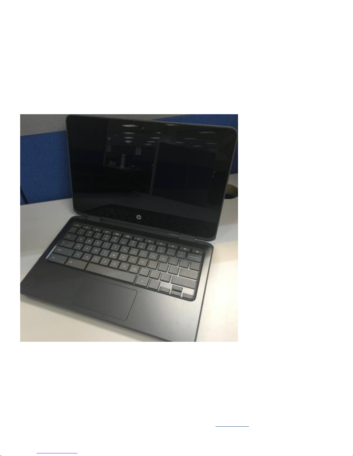
3.21 Total
3.22 Remove base screw
EL-MF877-00 Page 3
Template Revision B
PSG instructions for this template are available at EL-MF877-01
Page 4
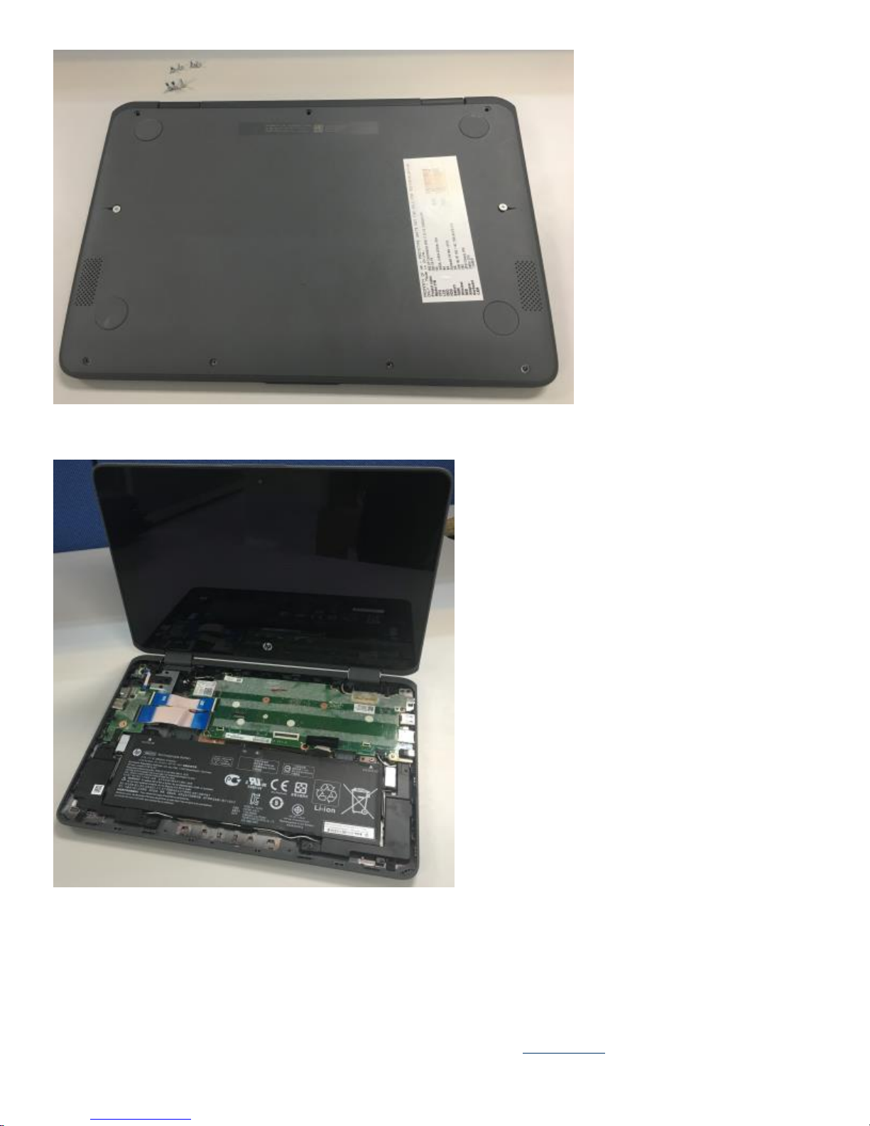
3.23 Remove TOP assy..
EL-MF877-00 Page 4
Template Revision B
PSG instructions for this template are available at EL-MF877-01
Page 5

3.24 Remove TP support bracket & TP module
EL-MF877-00 Page 5
Template Revision B
PSG instructions for this template are available at EL-MF877-01
Page 6

3.25 Remove speaker & battery pack & WLAN module
3.26 Remove D/B & D/B FFC & POWER Board & M/B
EL-MF877-00 Page 6
Template Revision B
PSG instructions for this template are available at EL-MF877-01
Page 7

EL-MF877-00 Page 7
Template Revision B
PSG instructions for this template are available at EL-MF877-01
Page 8

EL-MF877-00 Page 8
Template Revision B
PSG instructions for this template are available at EL-MF877-01
Page 9

3.27 Remove LCD bezel with Glass
3.28 Remove right side hinge
3.29 Remove camera module and hinge -L & LCD cable & antenna cable
EL-MF877-00 Page 9
Template Revision B
PSG instructions for this template are available at EL-MF877-01
Page 10

EL-MF877-00 Page 10
Template Revision B
PSG instructions for this template are available at EL-MF877-01
Page 11

EL-MF877-00 Page 11
Template Revision B
PSG instructions for this template are available at EL-MF877-01
 Loading...