

Page 1

HP Chromebook PC
Maintenance and Service Guide
IMPORTANT! This document is intended for
HP authorized service providers only.
Page 2

© Copyright 2018 HP Development Company,
L.P.
NVIDIA is a trademark or registered trademark
of NVIDIA Corporation in the U.S. and other
countries. Bluetooth is a trademark owned by
its proprietor and used by HP Inc. under license.
Intel, Pentium, and Core are trademarks of Intel
Corporation in the U.S. and other countries.
The information contained herein is subject to
change without notice. The only warranties for
HP products and services are set forth in the
express warranty statements accompanying
such products and services. Nothing herein
should be construed as constituting an
additional warranty. HP shall not be liable for
technical or editorial errors or omissions
contained herein.
First Edition: May 2018
Document Part Number: L15921-001
Product notice
This guide describes features that are common
to most models. Some features may not be
available on your computer.
Software terms
By installing, copying, downloading, or
otherwise using any software product
preinstalled on this computer, you agree to be
bound by the terms of the HP End User License
Agreement (EULA). If you do not accept these
license terms, your sole remedy is to return the
entire unused product (hardware and software)
within 14 days for a full refund subject to the
refund policy of your seller.
For any further information or to request a full
refund of the price of the computer, please
contact your seller.
Page 3

Safety warning notice
WARNING! To reduce the possibility of heat-related injuries or of overheating the device, do not place the
device directly on your lap or obstruct the device air vents. Use the device only on a hard, at surface. Do not
allow another hard surface, such as an adjoining optional printer, or a soft surface, such as pillows or rugs or
clothing, to block airow. Also, do not allow the AC adapter to contact the skin or a soft surface, such as
pillows or rugs or clothing, during operation. The device and the AC adapter comply with the user-accessible
surface temperature limits dened by the International Standard for Safety of Information Technology
Equipment (IEC 60950-1).
iii
Page 4

iv Safety warning notice
Page 5

Table of contents
1 Product description ....................................................................................................................................... 1
2 External component identication .................................................................................................................. 3
Right side ............................................................................................................................................................... 3
Left side ................................................................................................................................................................. 4
Display .................................................................................................................................................................... 5
Rear display ............................................................................................................................................................ 6
Top edge ................................................................................................................................................................. 7
Bottom edge .......................................................................................................................................................... 8
Labels ..................................................................................................................................................................... 9
3 Illustrated parts catalog .............................................................................................................................. 11
Computer major components .............................................................................................................................. 11
Miscellaneous parts ............................................................................................................................................. 13
4 Removal and replacement. procedures preliminary requirements ................................................................... 14
Tools required ...................................................................................................................................................... 14
Service considerations ......................................................................................................................................... 14
Plastic parts ....................................................................................................................................... 14
Cables and connectors ...................................................................................................................... 15
Grounding guidelines ........................................................................................................................................... 16
Electrostatic discharge damage ........................................................................................................ 16
Packaging and transporting guidelines .......................................................................... 17
Workstation guidelines ................................................................................................... 17
Equipment guidelines ..................................................................................................... 18
5 Removal and replacement procedures for authorized service provider parts .................................................... 19
Component replacement procedures .................................................................................................................. 19
Display panel assembly ..................................................................................................................... 20
Touchscreen control board ................................................................................................................ 22
Display panel cable ........................................................................................................................... 23
Battery ............................................................................................................................................... 24
Audio board ....................................................................................................................................... 25
Power button board .......................................................................................................................... 26
Right speaker ..................................................................................................................................... 27
Volume button board ........................................................................................................................ 29
v
Page 6

USB board .......................................................................................................................................... 30
POGO board ....................................................................................................................................... 32
Front webcam .................................................................................................................................... 33
Front microphone module ................................................................................................................. 34
WLAN antenna ................................................................................................................................... 35
Rear microphone module .................................................................................................................. 36
Rear webcam ..................................................................................................................................... 37
Left speaker ....................................................................................................................................... 38
System board .................................................................................................................................... 39
WLAN module .................................................................................................................................... 42
6 Specications .............................................................................................................................................. 44
Computer specications ...................................................................................................................................... 44
31.24 cm (12.3 in) display specications ............................................................................................................ 45
7 Power cord set requirements ........................................................................................................................ 46
Requirements for all countries ............................................................................................................................ 46
Requirements for specic countries and regions ................................................................................................ 47
8 Recycling .................................................................................................................................................... 49
Index ............................................................................................................................................................. 50
vi
Page 7

1 Product description
Category Description
Product Name HP Chromebook PC
Models: XXXX
Processors
Graphics Internal graphics:
Panel 12.3 in BrightView Ultra Wide Aspect Ratio, WLED (2400 × 1600) ultraslim
Memory LPDDR3 1866 MHz
eMMC For models equipped with the i5–7Y54 processor:
Intel® Core™ i5-7Y54 (1.0 GHz, turbo to 3.2 GHz), 8 GB 1866 MHz L3, Dual, HDCP
Intel M3-7Y30 (1.0 GHz), 4/8 GB 1866 MHz L3, Dual, HDCP
Intel Pentium™ 4415Y
Intel HD Graphics 615
Supports eDP 1.3+PSR
Supports up to 64 GB max system memory in the following congurations:
●
65536 MB (32768 MB × 2)
●
49152 MB (32768 MB × 1 + 16384 MB × 1)
●
16384 MB (16384 MB × 1)
65536 MB
For models equipped with an M3–7Y30 processor:
65536 MB
32786 MB
For models equipped with an Pentium 4415Y processor:
32786 MB
Audio and video B&O Play dual speakers
Cameras:
●
Rear: MIPI-RAW 13 MP
●
Front: MIPI-RAW 5 MP
Wireless Intel Stone Peak 2 D1 7265 ac 2×2 + Bluetooth 4.2 M.2 non-vPro PCI-e WW with dual antenna
External media cards HP Multi-Format Digital Media Card Reader
Supports SD/SDHC/SDXC
Push-Push insertion/removal
Ports HDMI v1.4
1
Page 8

Category Description
Audio-out (headphone)/Audio-in (microphone) combo jack
USB Type-C power connector and charging port
USB Type-C port
USB 3.x ports (2)
Keyboard/pointing
devices
Power requirements 4 Cell WHr 48 Long Life -PL Fast Charge battery
Security TPM 2.0
Operating system ChromeOS (64-bit)
Serviceability End user replaceable parts:
Oxford Blue Island Style Keyboard Textured Touchpad Backlit Standard Notebook Keyboard
Oxford Blue Island Style Keyboard Textured Touchpad Standard Notebook Keyboard
45 W nPFC USB Type-C AC adapter
Security lock slot
AC adapter
Digital pen
2 Chapter 1 Product description
Page 9
2 External component identication
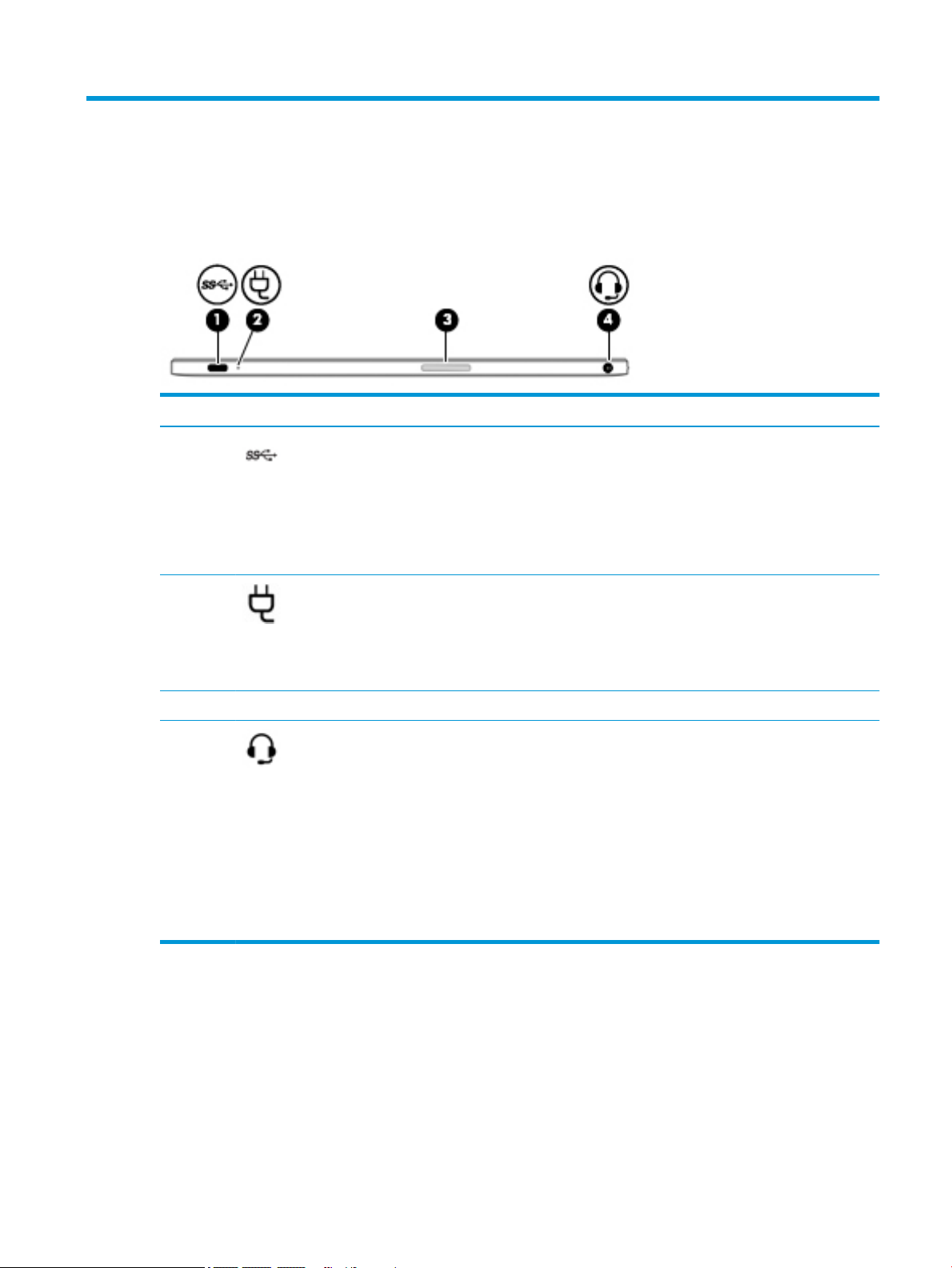
Right side
Component Description
(1) USB Type-C power connector and charging
port
(2) AC adapter and battery light
(3) Volume button Controls speaker volume on the tablet.
(4) Audio-out (headphone)/Audio-in
(microphone) combo jack
Connects an AC adapter that has a USB Type-C connector,
supplying power to the computer and, if needed, charging
the computer battery.
– and –
Connects a USB device that has a Type-C connector, such as
a cell phone, camera, activity tracker, or smartwatch, and
provides high-speed data transfer.
●
White: The AC adapter is connected and the battery is
charged.
●
Amber: The AC adapter is connected and the battery is
charging.
●
O: The computer is using battery power.
Connects optional powered stereo speakers, headphones,
earbuds, a headset, or a television audio cable. Also
connects an optional headset microphone. This jack does not
support optional standalone microphones.
WARNING! To reduce the risk of personal injury, adjust the
volume before putting on headphones, earbuds, or a
headset. For additional safety information, refer to the
Regulatory, Safety, and Environmental Notices.
This guide is provided in the box.
NOTE: When a device is connected to the jack, the
computer speakers are disabled.
Right side 3
Page 10
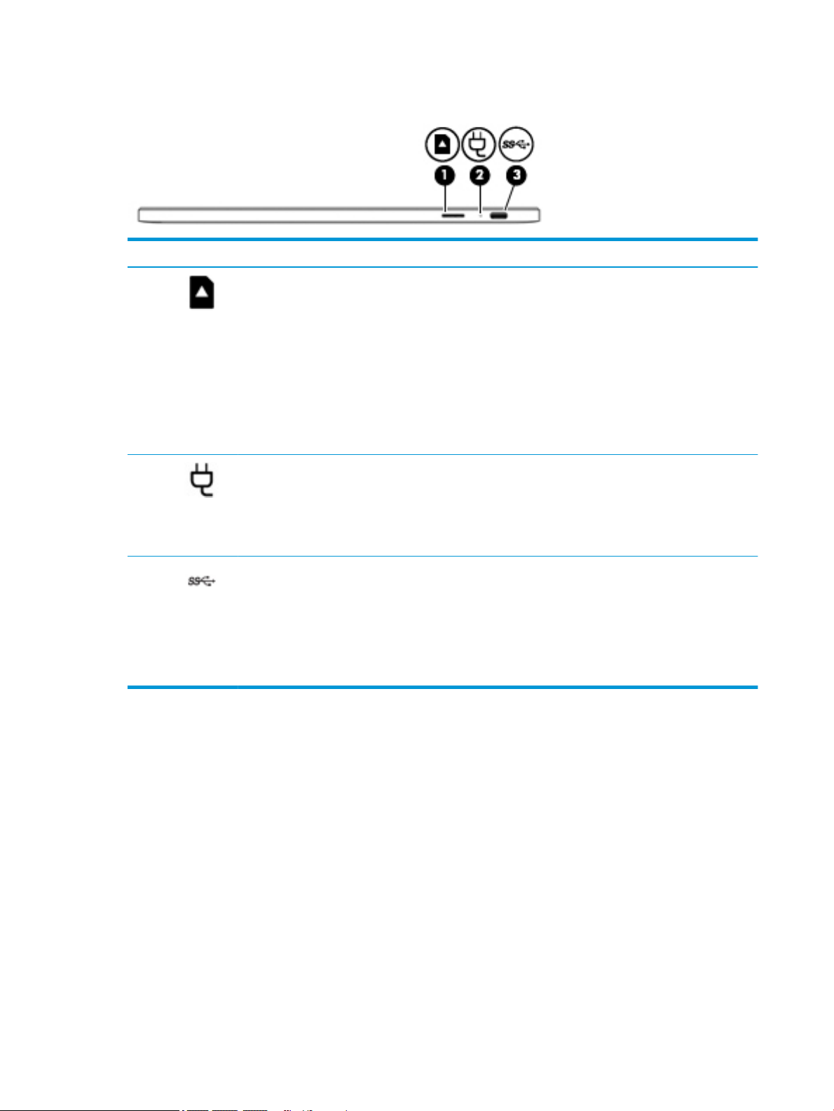
Left side
Component Description
(1) Memory card reader Reads optional memory cards that enable you to store,
manage, share, or access information.
To insert a card:
1. Hold the card label-side up, with connectors facing the
computer.
2. Insert the card into the memory card reader, and then
press in on the card until it is rmly seated.
To remove a card:
▲ Pull out the card.
(2) AC adapter and battery light
(3) USB Type-C power connector and port Connects an AC adapter that has a USB Type-C connector,
●
White: The AC adapter is connected and the battery is
charged.
●
Amber: The AC adapter is connected and the battery is
charging.
●
O: The computer is using battery power.
supplying power to the computer and, if needed, charging the
computer battery.
– and –
Connects a USB device that has a Type-C connector, such as a
cell phone, camera, activity tracker, or smartwatch, and
provides high-speed data transfer.
4 Chapter 2 External component identication
Page 11
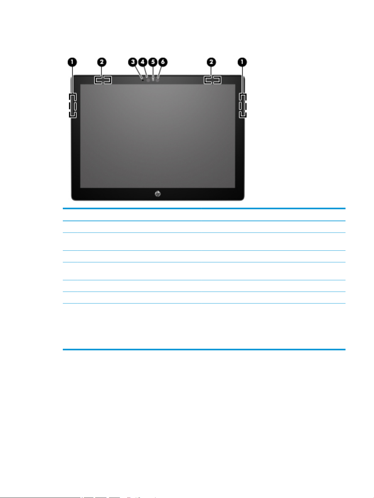
Display
Component Description
(1) Speakers (2) Produce sound.
(2) WLAN antennas* Send and receive wireless signals to communicate with wireless
local area networks (WLANs).
(3) Internal microphone Records sound.
(4) Ambient light sensor (select products only) Automatically adjusts the display brightness based on the lighting
conditions in your environment.
(5) Camera light On: The camera is in use.
(6) Camera Allows you to video chat, record video, and record still images.
*The antennas are not visible from the outside of the computer, and antenna location varies. For optimal transmission, keep the areas
immediately around the antennas free from obstructions.
For wireless regulatory notices, see the section of the Regulatory, Safety, and Environmental Notices that applies to your country or
region.
This guide is provided in the box.
Display 5
Page 12
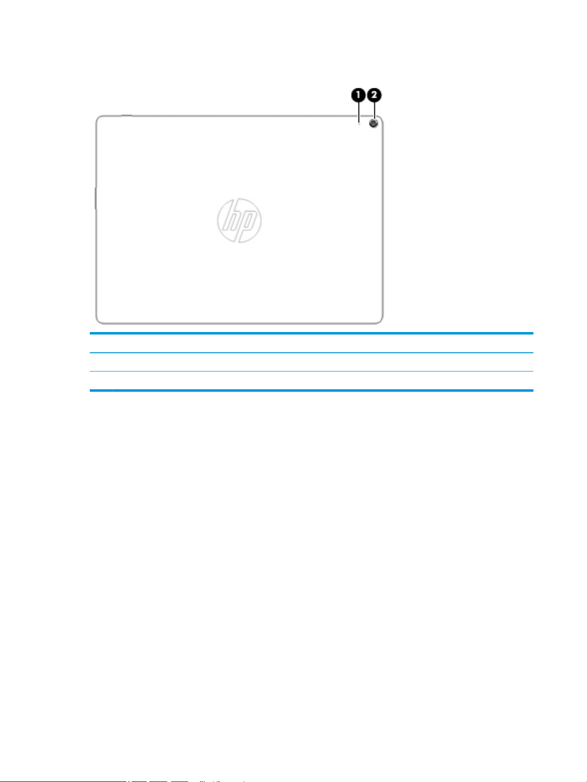
Rear display
Component Description
(1) Rear internal microphone Records sound.
(2) Rear camera Allows you to video chat, record video, and record still images.
6 Chapter 2 External component identication
Page 13

Top edge
Component Description
Power button
●
When the computer is o, press the button to turn on the
computer.
●
When the computer is in the Sleep state, press the button
briey to exit Sleep.
●
When the computer is on and you want to lock the screen, press
the button until you see the sign-in screen appear. Pressing the
power button during screen-lock mode turns o the computer.
●
When the computer is on and you want to turn it o, press and
hold the button to lock the screen, and then continue to press
the button until the computer turns o.
Top edge 7
Page 14
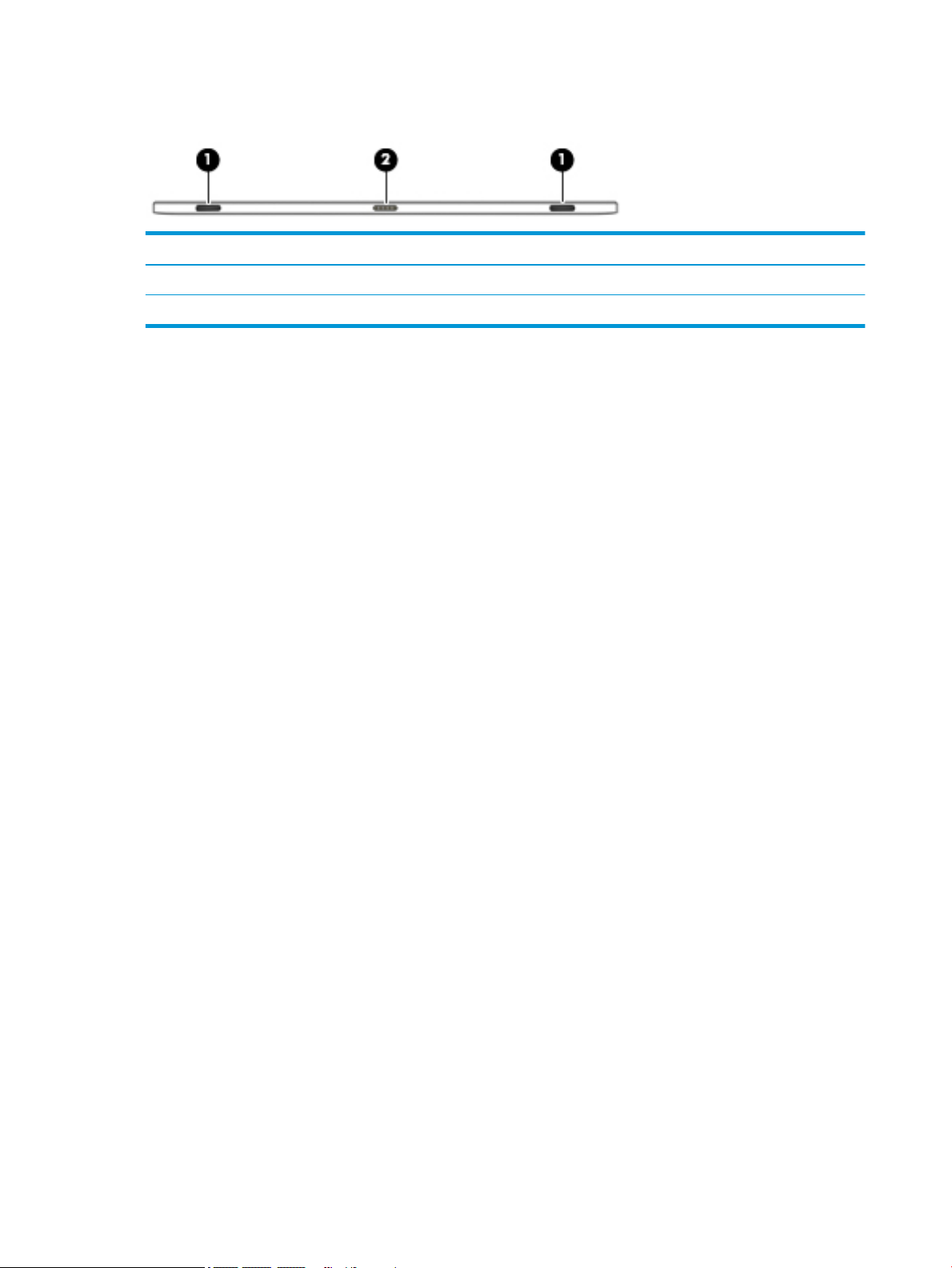
Bottom edge
Component Description
(1) Alignment posts (2) Guide the keyboard to the correct connection with the tablet.
(2) Docking port Connects the tablet to the keyboard base.
8 Chapter 2 External component identication
Page 15
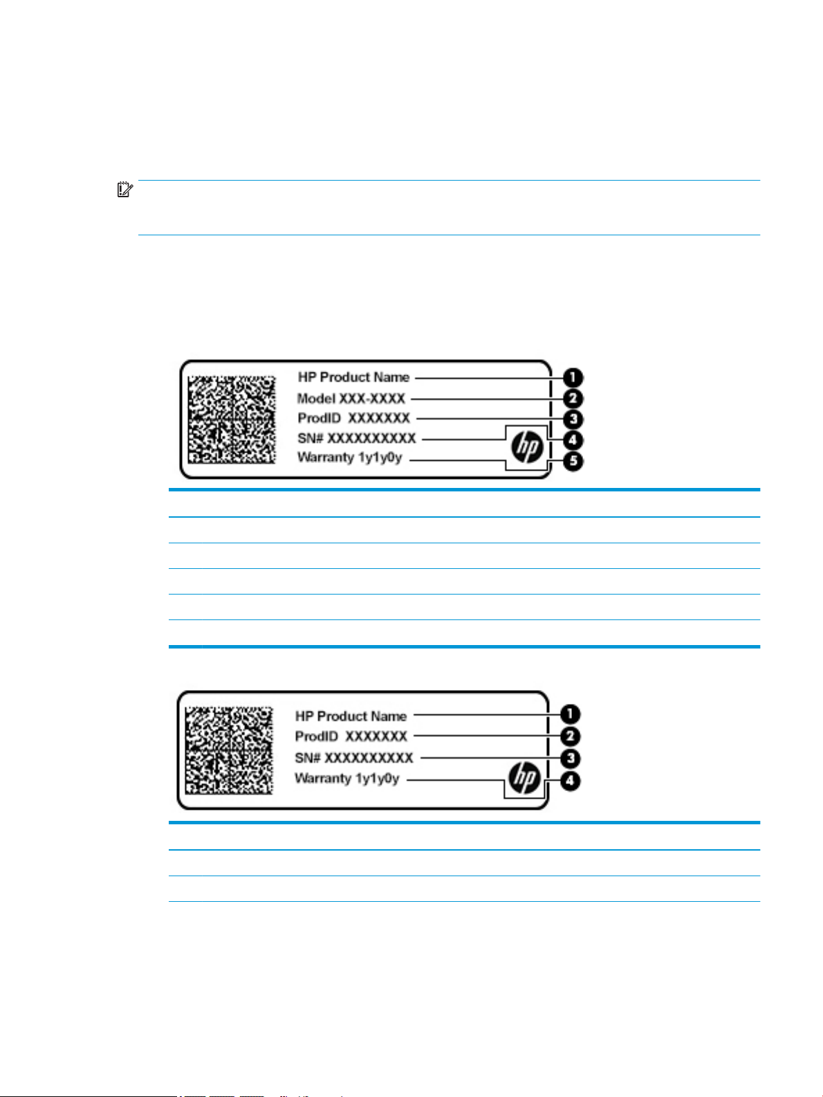
Labels
The labels axed to the computer provide information you may need when you troubleshoot system
problems or travel internationally with the computer. Labels may be in paper form or imprinted on the
product.
IMPORTANT: Check the following locations for the labels described in this section: the bottom of the
computer, inside the battery bay, under the service door, on the back of the display, or on the bottom of a
tablet kickstand.
●
Service label—Provides important information to identify your computer. When contacting support, you
may be asked for the serial number, the product number, or the model number. Locate this information
before you contact support.
Your service label will resemble one of the examples shown below. Refer to the illustration that most
closely matches the service label on your computer.
Component
(1) HP product name
(2) Model number
(3) Product ID
(4) Serial number
(5) Warranty period
Component
(1) HP product name
(2) Product ID
Labels 9
Page 16

Component
(3) Serial number
(4) Warranty period
●
Regulatory label(s)—Provide(s) regulatory information about the computer.
●
Wireless certication label(s)—Provide(s) information about optional wireless devices and the approval
markings for the countries or regions in which the devices have been approved for use.
10 Chapter 2 External component identication
Page 17
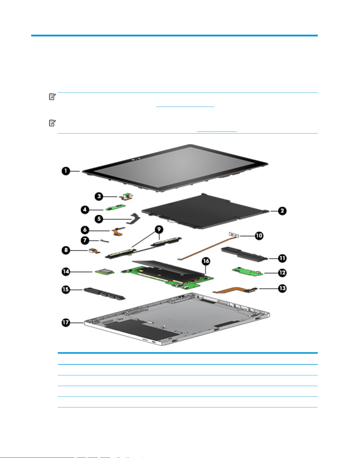
3 Illustrated parts catalog
Computer major components
NOTE: HP continually improves and changes product parts. For complete and current information on
supported parts for your computer, go to http://partsurfer.hp.com, select your country or region, and then
follow the on-screen instructions.
NOTE: Details about your computer, including model, serial number, product key, and length of warranty,
are on the service tag at the bottom of your computer. See Labels on page 9 for details.
Item Component Spare part number
(1) Display L17082-001
(2) Battery, 4-cell, 48 WHr 3.2 AH Li-ion 941617-855
(3) Audio board (includes cable) L17078-001
(4) Power button board (cable spared separately as L17066-001) not spared individually
Computer major components 11
Page 18

Item Component Spare part number
(5) Front webcam (includes webcam cable) not spared
(6) Front microphone (includes cable) L17075-001
(7) Rear microphone (includes cable) L17077-001
(8) Rear camera L17083-001
(9) Wireless antennas L17064-001
(10) Volume button board (includes cable) L17080-001
(11) Right speaker L17086-001
(12) USB board (cable spared separately as L17067-001) L17076-001
(13) POGO board (includes cable) L17081-001
(14) WLAN, Intel Stone Peak 2 D1 7265 ac 2×2 + Bluetooth 4.2 M.2 non-vPro PCI-e WW with
dual antenna
(15) Left speaker L17085-001
(16) System board
i5-7Y54 (1.0 GHz, turbo to 3.2 GHz), 8 GB 1866 MHz L3, Dual, HDCP
Includes 65536 MB eMMC SSD
M3-7Y30 (1.0 GHz), 8 GB 1866 MHz L3, Dual, HDCP
Includes 65536 MB eMMC SSD
M3-7Y30 (1.0 GHz), 8 GB 1866 MHz L3, Dual, HDCP
Includes 32786 MB eMMC SSD
M3-7Y30 (1.0 GHz), 4 GB 1866 MHz L3, Dual, HDCP
Includes 32786 MB eMMC SSD
Pentium 4415Y
Includes 32786 MB eMMC SSD
(17) Keyboard base
with backlight, for use in the United Kingdom L17090-031
with backlight, for use in the United States L17090-001
901229-855
L32397-001
L20788-001
L20787-001
L17088-001
L17087-001
without backlight, for use in the United Kingdom L20170-031
without backlight, for use in the United States L20170-001
12 Chapter 3 Illustrated parts catalog
Page 19

Miscellaneous parts
Component Spare part number
AC adapter 934739-850
Digital pen L23054-001
Power cord (black, 1 m):
For use in North America 920688-001
For use in the United Kingdom 920688-006
Screw kit L17089-001
Miscellaneous parts 13
Page 20

4 Removal and replacement. procedures
preliminary requirements
Tools required
You will need the following tools to complete the removal and replacement procedures:
●
Flat-bladed screwdriver
●
Magnetic screwdriver
●
Phillips P0 and P1 screwdrivers
Service considerations
The following sections include some of the considerations that you must keep in mind during disassembly
and assembly procedures.
NOTE: As you remove each subassembly from the computer, place the subassembly (and all accompanying
screws) away from the work area to prevent damage.
Plastic parts
CAUTION: Using excessive force during disassembly and reassembly can damage plastic parts. Use care
when handling the plastic
14 Chapter 4 Removal and replacement. procedures preliminary requirements
Page 21

Cables and connectors
CAUTION: When servicing the computer, be sure that cables are placed in their proper locations during the
reassembly process. Improper cable placement can damage the computer.
Cables must be handled with extreme care to avoid damage. Apply only the tension required to unseat or seat
the cables during removal and insertion. Handle cables by the connector whenever possible. In all cases, avoid
bending, twisting, or tearing cables. Be sure that cables are routed in such a way that they cannot be caught
or snagged by parts being removed or replaced. Handle ex cables with extreme care; these cables tear
easily.
Service considerations 15
Page 22

Grounding guidelines
Electrostatic discharge damage
Electronic components are sensitive to electrostatic discharge (ESD). Circuitry design and structure determine
the degree of sensitivity. Networks built into many integrated circuits provide some protection, but in many
cases, ESD contains enough power to alter device parameters or melt silicon junctions.
A discharge of static electricity from a nger or other conductor can destroy static-sensitive devices or
microcircuitry. Even if the spark is neither felt nor heard, damage may have occurred.
An electronic device exposed to ESD may not be aected at all and can work perfectly throughout a normal
cycle. Or the device may function normally for a while, then degrade in the internal layers, reducing its life
expectancy.
CAUTION: To prevent damage to the computer when you are removing or installing internal components,
observe these precautions:
Keep components in their electrostatic-safe containers until you are ready to install them.
Before touching an electronic component, discharge static electricity by using the guidelines described in this
section.
Avoid touching pins, leads, and circuitry. Handle electronic components as little as possible.
If you remove a component, place it in an electrostatic-safe container.
The following table shows how humidity aects the electrostatic voltage levels generated by dierent
activities.
CAUTION: A product can be degraded by as little as 700 V.
Typical electrostatic voltage levels
Relative humidity
Event 10% 40% 55%
Walking across carpet 35,000 V 15,000 V 7,500 V
Walking across vinyl oor 12,000 V 5,000 V 3,000 V
Motions of bench worker 6,000 V 800 V 400 V
Removing DIPS from plastic tube 2,000 V 700 V 400 V
Removing DIPS from vinyl tray 11,500 V 4,000 V 2,000 V
Removing DIPS from plastic foam 14,500 V 5,000 V 3,500 V
Removing bubble pack from PCB 26,500 V 20,000 V 7,000 V
Packing PCBs in foam-lined box 21,000 V 11,000 V 5,000 V
16 Chapter 4 Removal and replacement. procedures preliminary requirements
Page 23

Packaging and transporting guidelines
Follow these grounding guidelines when packaging and transporting equipment:
●
To avoid hand contact, transport products in static-safe tubes, bags, or boxes.
●
Protect ESD-sensitive parts and assemblies with conductive or approved containers or packaging.
●
Keep ESD-sensitive parts in their containers until the parts arrive at static-free workstations.
●
Place items on a grounded surface before removing items from their containers.
●
Always be properly grounded when touching a component or assembly.
●
Store reusable ESD-sensitive parts from assemblies in protective packaging or nonconductive foam.
●
Use transporters and conveyors made of antistatic belts and roller bushings. Be sure that mechanized
equipment used for moving materials is wired to ground and that proper materials are selected to avoid
static charging. When grounding is not possible, use an ionizer to dissipate electric charges.
Workstation guidelines
Follow these grounding workstation guidelines:
●
Cover the workstation with approved static-shielding material.
●
Use a wrist strap connected to a properly grounded work surface and use properly grounded tools and
equipment.
●
Use conductive eld service tools, such as cutters, screwdrivers, and vacuums.
●
When xtures must directly contact dissipative surfaces, use xtures made only of static safe materials.
●
Keep the work area free of nonconductive materials, such as ordinary plastic assembly aids and plastic
foam.
●
Handle ESD-sensitive components, parts, and assemblies by the case or PCM laminate. Handle these
items only at static-free workstations.
●
Avoid contact with pins, leads, or circuitry.
●
Turn o power and input signals before inserting or removing connectors or test equipment.
Grounding guidelines 17
Page 24

Equipment guidelines
Grounding equipment must include either a wrist strap or a foot strap at a grounded workstation.
●
When seated, wear a wrist strap connected to a grounded system. Wrist straps are exible straps with a
minimum of one megohm ±10% resistance in the ground cords. To provide proper ground, wear a strap
snugly against the skin at all times. On grounded mats with banana-plug connectors, use alligator clips
to connect a wrist strap.
●
When standing, use foot straps and a grounded oor mat. Foot straps (heel, toe, or boot straps) can be
used at standing workstations and are compatible with most types of shoes or boots. On conductive
oors or dissipative oor mats, use foot straps on both feet with a minimum of one megohm resistance
between the operator and ground. To be eective, the conductive equipment must be worn in contact
with the skin.
The following grounding equipment is recommended to prevent electrostatic damage:
●
Antistatic tape
●
Antistatic smocks, aprons, and sleeve protectors
●
Conductive bins and other assembly or soldering aids
●
Nonconductive foam
●
Conductive tabletop workstations with ground cords of one megohm resistance
●
Static-dissipative tables or oor mats with hard ties to the ground
●
Field service kits
●
Static awareness labels
●
Material-handling packages
●
Nonconductive plastic bags, tubes, or boxes
●
Metal tote boxes
●
Electrostatic voltage levels and protective materials
The following table lists the shielding protection provided by antistatic bags and oor mats.
Material Use Voltage protection level
Antistatic plastics Bags 1,500 V
Carbon-loaded plastic Floor mats 7,500 V
Metallized laminate Floor mats 5,000 V
18 Chapter 4 Removal and replacement. procedures preliminary requirements
Page 25

5 Removal and replacement procedures for
authorized service provider parts
CAUTION: Components described in this chapter should be accessed only by an authorized service provider.
Accessing these parts can damage the computer or void the warranty.
CAUTION: This computer does not have user-replaceable parts. Only HP authorized service providers should
perform the removal and replacement procedures described here. Accessing the internal part could damage
the computer or void the warranty.
Component replacement procedures
NOTE: Details about your computer, including model, serial number, product key, and length of warranty,
are on the service tag at the bottom of your computer. See Labels on page 9 for details.
NOTE: HP continually improves and changes product parts. For complete and current information on
supported parts for your computer, go to http://partsurfer.hp.com, select your country or region, and then
follow the on-screen instructions.
There are as many as 48 screws that must be removed, replaced, and/or loosened when servicing the parts
described in this chapter. Make special note of each screw size and location during removal and replacement..
Component replacement procedures 19
Page 26

Display panel assembly
NOTE: The display panel spare part kit includes the touchscreen control board, but does not include the
touchscreen control board cable or display cable.
Description Spare part number
Display panel, 12.3 in BrightView Ultra Wide Aspect Ratio, WLED (2400 × 1600) ultraslim, eDP 1.3 + PSR L17082-001
Display cable L17069-001
Touchscreen control board cable L17068-001
IMPORTANT: Make special note of each screw and screw lock size and location during removal
and replacement.
Before removing the display panel, follow these steps:
1. Shut down the computer.
2. Disconnect all external devices connected to the computer.
3. Disconnect the power from the computer by rst unplugging the power cord from the AC outlet and then
unplugging the AC adapter from the computer.
Remove the display panel:
1. Insert a case insertion tool between the base enclosure and the slate screen(1).
2. Lift the display panel up and to the rear(2).
CAUTION: Use care when rotating the display panel to avoid damaging the touch panel control board
and display panel cables.
3. Release the touchscreen control board cable (1) from the zero-insertion force connector attached to the
base enclosure.
4. Remove the adhesive cover (2) from the display panel cable (3).
5. Release the display panel cable from the ZIF connector on the base enclosure (4).
20 Chapter 5 Removal and replacement procedures for authorized service provider parts
Page 27

6. Lift the display away from the base enclosure (5).
Reverse this procedure to install the display panel assembly.
Component replacement procedures 21
Page 28

Touchscreen control board
NOTE: The touchscreen control board is not spared separately.
IMPORTANT: Make special note of each screw and screw lock size and location during removal
and replacement.
Before removing the touchscreen control board, follow these steps:
1. Shut down the computer.
2. Disconnect all external devices connected to the computer.
3. Disconnect the power from the computer by rst unplugging the power cord from the AC outlet and then
unplugging the AC adapter from the computer.
4. Remove the display panel assembly (see Display panel assembly on page 20).
Remove the touchscreen control board:
1. Release the touchscreen control board cables from the ZIF connectors on the display panel (1).
2. Remove the touchscreen control board(2).
Reverse this procedure to install the touchscreen control board.
22 Chapter 5 Removal and replacement procedures for authorized service provider parts
Page 29

Display panel cable
NOTE: The display panel cable is not spared separately.
IMPORTANT: Make special note of each screw and screw lock size and location during removal
and replacement.
Before removing the display panel cable, follow these steps:
1. Shut down the computer.
2. Disconnect all external devices connected to the computer.
3. Disconnect the power from the computer by rst unplugging the power cord from the AC outlet and then
unplugging the AC adapter from the computer.
4. Remove the display panel assembly (see Display panel assembly on page 20).
Remove the display panel cable:
1. Remove the adhesive cover from the display panel cable (1).
2. Raise the retaining clip to release the display panel cable (2).
3. Remove the display panel cable (3).
Reverse this procedure to install the display panel cable.
Component replacement procedures 23
Page 30

Battery
Description Spare part number
Battery (4-cell, 48 WHr, 3.2 AH, Li-ion) 941617-855
IMPORTANT: Make special note of each screw and screw lock size and location during removal
and replacement.
Before removing the battery, follow these steps:
1. Shut down the computer.
2. Disconnect all external devices connected to the computer.
3. Disconnect the power from the computer by rst unplugging the power cord from the AC outlet and then
unplugging the AC adapter from the computer.
4. Remove the display panel (see Display panel assembly on page 20).
Remove the battery:
1. Release the adhesive cover from the battery (1).
CAUTION: To avoid damaging the system board, remove the adhesive cover only from the battery.
2. Release the battery cable from the system board (2).
3. Remove the ve Phillips M2.0 × 3.0 screws (3) that secure the battery to the base enclosure.
4. Remove the battery from the base enclosure (4).
Reverse this procedure to install the battery.
24 Chapter 5 Removal and replacement procedures for authorized service provider parts
Page 31

Audio board
NOTE: The audio board spare part kit includes the audio board cable and power button board.
Description Spare part number
Audio board L17078-001
IMPORTANT: Make special note of each screw and screw lock size and location during removal
and replacement.
Before removing the audio board, follow these steps:
1. Shut down the computer.
2. Disconnect all external devices connected to the computer.
3. Disconnect the power from the computer by rst unplugging the power cord from the AC outlet and then
4. Remove the display panel (see Display panel assembly on page 20), and then remove the following
Remove the audio board:
unplugging the AC adapter from the computer.
components:
▲
Battery (see Battery on page 24).
1. Release the audio board cable from the ZIF connector that secures it to the base enclosure (1).
2. Remove the Phillips M2.0 × 3.0 screw (2) that secures the audio board to the base enclosure.
3. Remove the audio board from the base enclosure (3).
Reverse this procedure to install the audio board.
Component replacement procedures 25
Page 32

Power button board
NOTE: The power button board is included with the audio board (spare part number L17078-001). The
power button board cable is spared separately.
Description Spare part number
Power button board cable L17066-001
IMPORTANT: Make special note of each screw and screw lock size and location during removal
and replacement.
Before removing the power button board, follow these steps:
1. Shut down the computer.
2. Disconnect all external devices connected to the computer.
3. Disconnect the power from the computer by rst unplugging the power cord from the AC outlet and then
unplugging the AC adapter from the computer.
4. Remove the display panel (see Display panel assembly on page 20), and then remove the following
component:
▲
Battery (see Battery on page 24).
Remove the power button board:
1. Release the audio board cable from the ZIF connector (1) that secures it to the power button board.
2. Release the power button board cable from the ZIF connector (2) that secures it to the power button
board.
3. Remove the power button board (3).
26 Chapter 5 Removal and replacement procedures for authorized service provider parts
Page 33

Reverse this procedure to install the power button board.
Right speaker
Description Spare part number
speaker, right xxxxxx-001
IMPORTANT: Make special note of each screw and screw lock size and location during removal
and replacement.
Before removing the right speaker, follow these steps:
1. Shut down the computer.
2. Disconnect all external devices connected to the computer.
3. Disconnect the power from the computer by rst unplugging the power cord from the AC outlet and then
unplugging the AC adapter from the computer.
4. Remove the display panel (see Display panel assembly on page 20), and then remove the following
components:
▲
Remove the right speaker:
Battery (see Battery on page 24).
1. Release the speaker cable from the USB board (1).
2. Remove the two Phillips M2.0 × 3.0 screws (2) that secure the speaker to the base enclosure.
3. Remove the speaker(3).
4. Detach and replace the volume button board and volume button board cable from the right speaker (1)
before completely removing the speaker from the computer.
Component replacement procedures 27
Page 34

5. Replace the volume button board in the side of the base enclosure (2).
Reverse this procedure to install the right speaker.
28 Chapter 5 Removal and replacement procedures for authorized service provider parts
Page 35

Volume button board
NOTE: The volume button board spare part kit includes the volume button board cable.
Description Spare part number
Volume button board L17080-001
Volume button board bracket L17072-001
IMPORTANT: Make special note of each screw and screw lock size and location during removal
and replacement.
Before removing the volume button board, follow these steps:
1. Shut down the computer.
2. Disconnect all external devices connected to the computer.
3. Disconnect the power from the computer by rst unplugging the power cord from the AC outlet and then
unplugging the AC adapter from the computer.
4. Remove the display panel (see Display panel assembly on page 20), and then remove the following
components:
a. Battery (see Battery on page 24).
b. Right speaker (see Right speaker on page 27).
Remove the volume button board:
1. Release the volume button board cable from the ZIF connector on the system board (1) .
2. Remove the volume button board from the base enclosure (2).
3. Remove the volume button board bracket (3).
Component replacement procedures 29
Page 36

Reverse this procedure to install the volume button board.
USB board
NOTE: The USB board spare part kit does not include the USB board cable.
Description Spare part number
USB board L17076-001
USB board bracket L17073-001
USB board cable L17067-001
IMPORTANT: Make special note of each screw and screw lock size and location during removal
and replacement.
Before removing the USB board, follow these steps:
1. Shut down the computer.
2. Disconnect all external devices connected to the computer.
3. Disconnect the power from the computer by rst unplugging the power cord from the AC outlet and then
unplugging the AC adapter from the computer.
4. Remove the display panel (see Display panel assembly on page 20), and then remove the following
component:
▲
Battery (see Battery on page 24).
Remove the USB board:
1. Release the ZIF connector from the system board and USB board (1).
30 Chapter 5 Removal and replacement procedures for authorized service provider parts
Page 37

2. Remove the USB board cable from the base enclosure (2).
3. Release the ZIF connector from the USB board (1).
4. Remove the two Phillips M2.0 × 3.0 screws (2) that secure USB board bracket to the USB board.
5. Release the ZIF connector from the system board and USB board (3).
6. Remove the USB board cable from the base enclosure (4).
Reverse this procedure to install the USB board.
Component replacement procedures 31
Page 38

POGO board
NOTE: The POGO board spare part kit includes the POGO board cable.
Description Spare part number
POGO board L17081-001
IMPORTANT: Make special note of each screw and screw lock size and location during removal
and replacement..
Before removing the POGO board, follow these steps:
1. Shut down the computer.
2. Disconnect all external devices connected to the computer.
3. Disconnect the power from the computer by rst unplugging the power cord from the AC outlet and then
4. Remove the display panel (see Display panel assembly on page 20), and then remove the following
Remove the POGO board:
unplugging the AC adapter from the computer.
component:
▲
Battery (see Battery on page 24).
1. Release the POGO board cable from the ZIF connector on the system board (1).
2. Remove the two Phillips M2.0 × 3.0 screws (2) that secure the POGO board to the base enclosure.
3. Remove the POGO board cable from the base enclosure (3).
4. Remove the POGO board from the base enclosure (4).
Reverse this procedure to install the POGO board.
32 Chapter 5 Removal and replacement procedures for authorized service provider parts
Page 39

Front webcam
NOTE: The front webcam spare part kit includes the webcam cable.
Description Spare part number
Front webcam xxxxxx-001
IMPORTANT: Make special note of each screw and screw lock size and location during removal
and replacement..
Before removing the front webcam, follow these steps:
1. Shut down the computer.
2. Disconnect all external devices connected to the computer.
3. Disconnect the power from the computer by rst unplugging the power cord from the AC outlet and then
unplugging the AC adapter from the computer.
4. Remove the display panel (see Display panel assembly on page 20), and then remove the following
component:
▲
Remove the front webcam:
Battery (see Battery on page 24).
1. Release the front webcam cable from the ZIF connector attaching it to the system board (1).
2. Remove the front webcam cable from the base enclosure (2).
3. Remove the front webcam from the base enclosure (3).
Reverse this procedure to install the front webcam.
Component replacement procedures 33
Page 40

Front microphone module
NOTE: The front microphone module spare part kit includes the microphone cable.
Description Spare part number
Front microphone module L17077-001
IMPORTANT: Make special note of each screw and screw lock size and location during removal
and replacement.
Before removing the front microphone module, follow these steps:
1. Shut down the computer.
2. Disconnect all external devices connected to the computer.
3. Disconnect the power from the computer by rst unplugging the power cord from the AC outlet and then
unplugging the AC adapter from the computer.
4. Remove the display panel (see Display panel assembly on page 20), and then remove the following
components:
▲
Battery (see Battery on page 24).
Remove the front microphone module:
1. Release the microphone cable from the ZIF connector on the system board (1).
2. Release the front microphone cable from the adhesive that secures it to the base enclosure (2).
3. Remove the front microphone module from the base enclosure (3).
Reverse this procedure to install the front microphone.
34 Chapter 5 Removal and replacement procedures for authorized service provider parts
Page 41

WLAN antenna
Description Spare part number
WLAN dual antenna module L17064-001
IMPORTANT: Make special note of each screw and screw lock size and location during removal
and replacement.
Before removing the WLAN antenna module, follow these steps:
1. Shut down the computer.
2. Disconnect all external devices connected to the computer.
3. Disconnect the power from the computer by rst unplugging the power cord from the AC outlet and then
unplugging the AC adapter from the computer.
4. Remove the display panel (see Display panel assembly on page 20), and then remove the following
components:
▲
Remove the WLAN antenna module:
1. Disconnect the WLAN antenna cables (1) from the terminals on the WLAN module.
Battery (see Battery on page 24).
2. Remove the four Phillips M2.0 × 3.0 screw (2) that secure the antennas to the base enclosure.
3. Remove the antennas from the base enclosure (3).
Reverse this procedure to install the WLAN antenna module.
Component replacement procedures 35
Page 42

Rear microphone module
Description Spare part number
Rear microphone module xxxxxx-001
IMPORTANT: Make special note of each screw and screw lock size and location during removal
and replacement.
Before removing the rear microphone module, follow these steps:
1. Shut down the computer.
2. Disconnect all external devices connected to the computer.
3. Disconnect the power from the computer by rst unplugging the power cord from the AC outlet and then
unplugging the AC adapter from the computer.
4. Remove the display panel (see Display panel assembly on page 20), and then remove the following
component:
▲
Battery (see Battery on page 24).
Remove the rear microphone module:
1. Release the microphone cable from the ZIF connector on the system board (1).
2. Remove the rear microphone module from the base enclosure (2).
Reverse this procedure to install the rear microphone module.
36 Chapter 5 Removal and replacement procedures for authorized service provider parts
Page 43

Rear webcam
Description Spare part number
Rear webcam L17083-001
IMPORTANT: Make special note of each screw and screw lock size and location during removal
and replacement.
Before removing the rear webcam, follow these steps:
1. Shut down the computer.
2. Disconnect all external devices connected to the computer.
3. Disconnect the power from the computer by rst unplugging the power cord from the AC outlet and then
unplugging the AC adapter from the computer.
4. Remove the display panel (see Display panel assembly on page 20), and then remove the following
components:
▲
Remove the rear webcam:
1. Release the rear webcam cable from the ZIF connector on the system board (1).
Battery (see Battery on page 24).
2. Remove the rear webcam from the base enclosure (2).
Reverse this procedure to install the rear webcam.
Component replacement procedures 37
Page 44

Left speaker
NOTE: The left speaker spare part kit includes xxxxxx
Description Spare part number
Left speaker L17085-001
IMPORTANT: Make special note of each screw and screw lock size and location during removal
and replacement.
Before removing the left speaker, follow these steps:
1. Shut down the computer.
2. Disconnect all external devices connected to the computer.
3. Disconnect the power from the computer by rst unplugging the power cord from the AC outlet and then
4. Remove the display panel (see Display panel assembly on page 20), and then remove the following
Remove the left speaker:
unplugging the AC adapter from the computer.
components:
▲
Battery (see Battery on page 24).
1. Disconnect the speaker cable from the system board (1).
2. Remove the two Phillips M2.0 × 3.0 screws (2) that secure the speaker to the base enclosure.
3. Remove the speaker from the base enclosure (3).
Reverse this procedure to install the left speaker.
38 Chapter 5 Removal and replacement procedures for authorized service provider parts
Page 45

System board
NOTE: The system board spare part kit includes a solid state drive, thermal material, heatsink, and adhesive
cover for the system board and battery.
Description Spare part number
i5-7Y54 (1.0 GHz, turbo to 3.2 GHz), 8 GB 1866 MHz L3, Dual, HDCP (includes 65536 MB eMMC SSD) L32397-001
M3-7Y30 (1.0 GHz), 8 GB 1866 MHz L3, Dual, HDCP (includes 65536 MB eMMC SSD) L20788-001
M3-7Y30 (1.0 GHz), 8 GB 1866 MHz L3, Dual, HDCP (includes 32786 MB eMMC SSD) L20787-001
M3-7Y30 (1.0 GHz), 4 GB 1866 MHz L3, Dual, HDCP (includes 32786 MB eMMC SSD) L17088-001
Pentium 4415Y (includes 32786 MB eMMC SSD) L17087-001
IMPORTANT: Make special note of each screw and screw lock size and location during removal
and replacement.
Before removing the system board, follow these steps:
1. Shut down the computer.
2. Disconnect all external devices connected to the computer.
3. Disconnect the power from the computer by rst unplugging the power cord from the AC outlet and then
unplugging the AC adapter from the computer.
4. Remove the display panel (see Display panel assembly on page 20), and then remove the following
component:
a. Battery (see Battery on page 24).
b. Left speaker(see Left speaker on page 38).
Disconnect the system board cables:
1. POGO board cable (1).
2. USB board cable (2).
3. Volume button board cable (3).
4. Power button board cable (4).
5. Front webcam cable (5).
6. Front microphone cable (6).
7. Rear microphone cable (7).
Component replacement procedures 39
Page 46

8. Rear webcam cable (8).
Remove the system board bracket:
1. Remove the two Phillips M2.0 × 2.0 screws (1) that secure the bracket to the system board.
2. Remove the system board bracket (2).
Remove the system board:
1. Remove the Phillips M2.0 × 1.5 screw (1) that secures the system board to the base enclosure.
40 Chapter 5 Removal and replacement procedures for authorized service provider parts
Page 47

2. Remove the system board (2).
Reverse this procedure to install the system board.
Component replacement procedures 41
Page 48

WLAN module
Description Spare part number
Intel Stone Peak 2 D1 7265 ac 2×2 + Bluetooth 4.2 M.2 non-vPro PCI-e WW with dual antenna 901229-855
IMPORTANT: Make special note of each screw and screw lock size and location during removal
and replacement.
Before removing the WLAN module, follow these steps:
1. Shut down the computer.
2. Disconnect all external devices connected to the computer.
3. Disconnect the power from the computer by rst unplugging the power cord from the AC outlet and then
unplugging the AC adapter from the computer.
4. Remove the display panel (see Display panel assembly on page 20), and then remove the following
components:
▲
Remove the WLAN module:
1. Disconnect the WLAN antenna cables (1) from the terminals on the WLAN module.
Battery (see Battery on page 24).
NOTE: The WLAN antenna cable labeled “1” connects to the WLAN module “Main” terminal labeled “1”.
The WLAN antenna cable labeled “2” connects to the WLAN module “Aux” terminal labeled “2”.
2. Remove the Phillips PM2.0×3.4 screw (2) that secures the WLAN module to the system board (the WLAN
module tilts up).
42 Chapter 5 Removal and replacement procedures for authorized service provider parts
Page 49

3. Remove the WLAN module (3) by pulling the module away from the slot at an angle.
Reverse this procedure to install the WLAN module.
Component replacement procedures 43
Page 50

6 Specications
Computer specications
Metric U.S.
Dimensions
Width 38.56 cm 15.18 in
Depth 25.8 cm 10.15 in
Height (front to back) 2.26 cm .89 in
Weight 2.09 or 2.29 kg (depending on
conguration)
Input power
Operating voltage and current 19.5 V dc @ 3.33 A – 65 W
19 V dc @ 4.62 A – 90 W
19.5 V dc @ 2.31 – 45 W (select models only)
Temperature
Operating 5°C to 35°C 41°F to 95°F
Nonoperating ‑20°C to 60°C ‑4°F to 140°F
Relative humidity (noncondensing)
Operating 10% to 90%
Nonoperating 5% to 95%
Maximum altitude (unpressurized)
Operating ‑15 m to 3,048 m ‑50 ft to 10,000 ft
Nonoperating ‑15 m to 12,192 m ‑50 ft to 40,000 ft
NOTE: Applicable product safety standards specify thermal limits for plastic surfaces. The device operates well within this range of
temperatures.
4.61 lb or 5.05 (depending on
conguration)
44 Chapter 6 Specications
Page 51

31.24 cm (12.3 in) display specications
Metric U.S.
Dimensions
Height 20.77 cm 8.175 in
Width 37.78 cm 14.875 in
Diagonal 39.62 cm 15.6 in
Number of colors Up to 16.8 million
Contrast ratio 500:1 (typical)
Brightness 200 nits
Pixel resolution
Pitch 0.252 mm x 0.252 mm
Format 1366×768
Conguration RGB vertical stripe
Backlight LED
Character display 80 × 25
Total power consumption 2.0 W
Viewing angle ±65° horizontal, ±50° vertical (typical)
31.24 cm (12.3 in) display specications 45
Page 52

7 Power cord set requirements
The wide-range input feature of the computer permits it to operate from any line voltage from 100 to 120 V
ac, or from 220 to 240 V ac.
The 3-conductor power cord set included with the computer meets the requirements for use in the country or
region where the equipment is purchased.
Power cord sets for use in other countries or regions must meet the requirements of the country and region
where the computer is used.
Requirements for all countries
The following requirements are applicable to all countries and regions:
●
The length of the power cord set must be at least 1.0 m (3.3 ft) and no more than 2.0 m (6.5 ft).
●
All power cord sets must be approved by an acceptable accredited agency responsible for evaluation in
the country or region where the power cord set will be used.
●
The power cord sets must have a minimum current capacity of 10 A and a nominal voltage rating of 125
or 250 V ac, as required by the power system of each country or region.
●
The appliance coupler must meet the mechanical conguration of an EN 60 320/IEC 320 Standard Sheet
C13 connector for mating with the appliance inlet on the back of the computer.
46 Chapter 7 Power cord set requirements
Page 53

Requirements for specic countries and regions
Country/region Accredited agency Applicable note number
Argentina IRAM 1
Australia SAA 1
Austria OVE 1
Belgium CEBEC 1
Brazil ABNT 1
Canada CSA 2
Chile IMQ 1
Denmark DEMKO 1
Finland FIMKO 1
France UTE 1
Germany VDE 1
India BIS 1
Israel SII 1
Italy IMQ 1
Japan JIS 3
The Netherlands KEMA 1
New Zealand SANZ 1
Norway NEMKO 1
The People's Republic of China CCC 4
Saudi Arabia SASO 7
Singapore PSB 1
South Africa SABS 1
South Korea KTL 5
Sweden SEMKO 1
Switzerland SEV 1
Taiwan BSMI 6
Thailand TISI 1
The United Kingdom ASTA 1
The United States UL 2
1. The exible cord must be Type HO5VV-F, 3-conductor, 0.75 mm² conductor size. Power cord set ttings (appliance coupler and
wall plug) must bear the certication mark of the agency responsible for evaluation in the country or region where it will be used.
2. The exible cord must be Type SVT/SJT or equivalent, No. 18 AWG, 3-conductor. The wall plug must be a two-pole grounding type
with a NEMA 5-15P (15 A, 125 V ac) or NEMA 6-15P (15 A, 250 V ac) conguration. CSA or C-UL mark. UL le number must be on
each element.
Requirements for specic countries and regions 47
Page 54

Country/region Accredited agency Applicable note number
3. The appliance coupler, exible cord, and wall plug must bear a “T” mark and registration number in accordance with the Japanese
Dentori Law. The exible cord must be Type VCTF, 3-conductor, 0.75 mm² or 1.25 mm² conductor size. The wall plug must be a
two-pole grounding type with a Japanese Industrial Standard C8303 (7 A, 125 V ac) conguration.
4. The exible cord must be Type RVV, 3-conductor, 0.75 mm² conductor size. Power cord set ttings (appliance coupler and wall
plug) must bear the CCC certication mark.
5. The exible cord must be Type H05VV-F 3-conductor, 0.75 mm² conductor size. KTL logo and individual approval number must
be on each element. Corset approval number and logo must be printed on a ag label.
6. The exible cord must be Type HVCTF 3-conductor, 1.25 mm² conductor size. Power cord set ttings (appliance coupler, cable,
and wall plug) must bear the BSMI certication mark.
7. For 127 V ac, the exible cord must be Type SVT or SJT 3-conductor, 18 AWG, with plug NEMA 5-15P (15 A, 125 V ac), with UL and
CSA or C-UL marks. For 240 V ac, the exible cord must be Type H05VV-F 3-conductor, 0.75 mm² or 1.00 mm² conductor size,
with plug BS 1363/A with BSI or ASTA marks.
48 Chapter 7 Power cord set requirements
Page 55

8 Recycling
When a non-rechargeable or rechargeable battery has reached the end of its useful life, do not dispose of the
battery in general household waste. Follow the local laws and regulations in your area for battery disposal.
HP encourages customers to recycle used electronic hardware, HP original print cartridges, and rechargeable
batteries. For more information about recycling programs, see the HP Web site at http://www.hp.com/recycle.
49
Page 56

Index
A
AC adapter
spare part number 13
AC adapter light 3, 4
alignment pins, identifying 8
ambient light sensor, identifying 5
audio board
removal 25
spare part number 11, 25
audio, product description 1
audio-in (microphone) jack,
identifying 3
audio-out (headphone) jack,
identifying 3
B
battery
light 3, 4
removal 24
spare part number 11, 24
Bluetooth label 10
buttons
volume 3
buttons, power 7
C
camera light, identifying 5
camera, identifying 5, 6
camera, rear
spare part number 12
components
bottom edge 8
display 5
left side 4
rear display 6
right side 3
top edge 7
computer major components 11
computer specications 44
connector, power 3
D
Digital pen
spare part number 13
display
specications 45
Display panel
removal 20
spare part number 20
display panel
product description 1
display panel cable
removal 23
docking port, identifying 8
E
eMMC
product description 1
F
front microphone
spare part number 12
G
graphics, product description 1
H
headphone (audio-out) jack 3
I
internal microphone, identifying 5,
6
J
jacks
audio-in (microphone) 3
audio-out (headphone) 3
K
Keyboard
spare part number 12
keyboard
product description 2
L
labels
Bluetooth 10
regulatory 10
serial number 9
service 9
wireless certication 10
WLAN 10
lights
AC adapter and battery 3, 4
camera 5
M
memory card reader, identifying 4
memory card, identifying 4
memory module
product description 1
microphone
product description 1
microphone (audio-in) jack,
identifying 3
microphone, front
removal 34
spare part number 34
microphone, rear
removal 36
spare part number 12, 36
model name 1
O
operating system, product
description 2
P
POGO board
removal 32
spare part number 12, 32
pointing device, product
description 2
ports
product description 1
USB Type-C power connector and
port 4
power button board
removal 26
spare part number 11, 26
power button, identifying 7
power connector, identifying 3
50 Index
Page 57

power cord
requirements for all countries
46
requirements for specic
countries and regions 47
set requirements 46
spare part number 13
power requirements, product
description 2
processor
product description 1
product description
audio 1
display panel 1
eMMC 1
external media cards 1
graphics 1
keyboard 2
memory module 1
microphone 1
operating system 2
pointing device 2
ports 1
power requirements 2
processors 1
product name 1
security 2
serviceability 2
video 1
wireless 1
product name 1
product name and number,
computer 9
R
regulatory information
regulatory label 10
wireless certication labels 10
removal/replacement
procedures 19
S
screw kit
spare part number 13
security, product description 2
serial number, computer 9
service labels, locating 9
serviceability, product description 2
slots
memory card reader 4
speaker
spare part number 12
speaker, identifying 5
speaker, left
removal 38
spare part number 38
speaker, right
removal 27
spare part number 27
speakers
spare part number 12
specications
computer 44
display 45
system board
removal 39
spare part number 12, 39
T
Touchscreen control board
removal 22
spare part number 22, 23
traveling with the computer 10
U
USB board
removal 30
spare part number 12, 30
USB Type-C power connector and
charging port, identifying 3
USB Type-C power connector and
port 4
V
video, product description 1
volume button
spare part number 12
volume button board
removal 29
spare part number 29
volume button, identifying 3
W
webcam, front
removal 33
spare part number 33
webcam, rear
removal 37
spare part number 37
wireless antennas
spare part number 12
wireless certication label 10
wireless, product description 1
WLAN
spare part number 12
WLAN antenna module
removal 35
spare part number 35
WLAN antennas, identifying 5
WLAN device 10
WLAN label 10
WLAN module
removal 42
spare part number 42
Index 51
 Loading...