

Page 1

Maintenance and Service Guide
SUMMARY
This guide provides information about spare parts, removal and replacement of parts, security, backing up, and more.
Page 2

© Copyright 2020 HP Development Company,
L.P.
Bluetooth is a trademark owned by its
proprietor and used by HP Inc. under license.
Chrome, Chrome OS, Chromebook, Chromecast,
Google, and Google Drive are trademarks of
Google LLC. Intel, Core, and Pentium are
trademarks of Intel Corporation or its
subsidiaries in the U.S. and/or other countries.
SDHC, SDXC, and microSD are trademarks or
registered trademarks of SD-3C LLC. Microsoft
and Windows are either registered trademarks
or trademarks of Microsoft Corporation in the
United States and/or other countries. USB
Type-C® is a registered trademark of USB
Implementers Forum.
The information contained herein is subject to
change without notice. The only warranties for
HP products and services are set forth in the
express warranty statements accompanying
such products and services. Nothing herein
should be construed as constituting an
additional warranty. HP shall not be liable for
technical or editorial errors or omissions
contained herein.
First Edition: June 2020
Product notice
This guide describes features that are common
to most models. Some features may not be
available on your computer.
To access the latest user guides, go to
http://www.hp.com/support, and follow the
instructions to nd your product. Then select
Manuals.
Software terms
By installing, copying, downloading, or
otherwise using any software product
preinstalled on this computer, you agree to be
bound by the terms of the HP End User License
Agreement (EULA). If you do not accept these
license terms, your sole remedy is to return the
entire unused product (hardware and software)
within 14 days for a full refund subject to the
refund policy of your seller.
For any further information or to request a full
refund of the price of the computer, please
contact your seller.
Document Part Number: L93860-001
Page 3

Safety warning notice
Reduce the possibility of heat-related injuries or of overheating the computer by following the practices
described.
WARNING! To reduce the possibility of heat-related injuries or of overheating the computer, do not place
the computer directly on your lap or obstruct the computer air vents. Use the computer only on a hard, at
surface. Do not allow another hard surface, such as an adjoining optional printer, or a soft surface, such as
pillows or rugs or clothing, to block airow. Also, do not allow the AC adapter to come into contact with the
skin or a soft surface, such as pillows or rugs or clothing, during operation. The computer and the AC adapter
comply with the user-accessible surface temperature limits dened by applicable safety standards.
iii
Page 4

iv Safety warning notice
Page 5

Table of contents
1 Product description ....................................................................................................................................... 1
2 Components .................................................................................................................................................. 5
Right side ............................................................................................................................................................... 5
Left side ................................................................................................................................................................. 6
Display .................................................................................................................................................................... 7
Keyboard area ........................................................................................................................................................ 8
Touchpad ............................................................................................................................................. 8
Button, speakers and ngerprint reader ............................................................................................ 9
Special keys ....................................................................................................................................... 10
Bottom ................................................................................................................................................................. 10
Labels ................................................................................................................................................................... 11
3 Illustrated parts catalog .............................................................................................................................. 13
Computer major components .............................................................................................................................. 13
Display assembly subcomponents ...................................................................................................................... 15
Cables ................................................................................................................................................................... 16
Miscellaneous parts ............................................................................................................................................. 16
4 Removal and replacement procedures preliminary requirements .................................................................... 19
Tools required ...................................................................................................................................................... 19
Service considerations ......................................................................................................................................... 19
Plastic parts ....................................................................................................................................... 19
Cables and connectors ...................................................................................................................... 19
Drive handling ................................................................................................................................... 19
Workstation guidelines ..................................................................................................................... 20
Electrostatic discharge information .................................................................................................................... 20
Generating static electricity .............................................................................................................. 21
Preventing electrostatic damage to equipment ............................................................................... 21
Personal grounding methods and equipment .................................................................................. 22
Grounding the work area ................................................................................................................... 22
Recommended materials and equipment ........................................................................................ 22
Packaging and transporting guidelines .............................................................................................................. 23
5 Removal and replacement procedures for authorized service provider parts .................................................... 25
Component replacement procedures .................................................................................................................. 25
v
Page 6

Preparation for disassembly ............................................................................................................. 25
Bottom cover ..................................................................................................................................... 25
Battery ............................................................................................................................................... 26
Speakers ............................................................................................................................................ 28
Touchpad ........................................................................................................................................... 29
Fingerprint sensor board .................................................................................................................. 31
Fan ..................................................................................................................................................... 32
Heat sink ............................................................................................................................................ 33
USB board .......................................................................................................................................... 35
USB door ............................................................................................................................................ 35
System board .................................................................................................................................... 38
Display assembly ............................................................................................................................... 40
Keyboard with top cover ................................................................................................................... 48
6 Backing up, resetting, and recovering ........................................................................................................... 51
Backing up ............................................................................................................................................................ 51
Resetting .............................................................................................................................................................. 51
Recovering ........................................................................................................................................................... 51
Installing the Chromebook Recovery Utility ..................................................................................... 51
Creating recovery media ................................................................................................................... 52
Recovering the Chrome operating system ....................................................................................... 52
Setting up your computer after a reset or recovery ........................................................................................... 52
Erase and reformat the recovery media .............................................................................................................. 52
7 Specications .............................................................................................................................................. 53
Computer specications ...................................................................................................................................... 53
35.6 cm (14.0 in) display specications .............................................................................................................. 53
8 Statement of memory volatility .................................................................................................................... 55
Current BIOS steps ............................................................................................................................................... 55
Nonvolatile memory usage ................................................................................................................................. 57
Questions and answers ....................................................................................................................................... 59
Using HP Sure Start (select products only) ......................................................................................................... 60
9 Power cord set requirements ........................................................................................................................ 61
Requirements for all countries ............................................................................................................................ 61
Requirements for specic countries and regions ................................................................................................ 61
10 Recycling .................................................................................................................................................. 63
vi
Page 7

Index ............................................................................................................................................................. 65
vii
Page 8

viii
Page 9

1 Product description
This table provides detailed product information.
Table 1-1 Product components and their descriptions
Category Description
Product Name HP Pro c640 Chromebook
Processors 10th Generation Intel® Core™ processors
Intel Core i7-10610U (1.8 GHz [turbo up to 4.9 GHz], 4 cores, 8 MB L3 cache, 15 W)
Intel Core i7-10510U (1.8 GHz [turbo up to 4.9 GHz], 4 cores, 8 MB L3 cache, 15 W)
Intel Core i5-10310U (1.7 GHz [turbo up to 4.4 GHz], 4 cores, 6 MB L3 cache, 15 W)
Intel Core i5-10210U (1.6 GHz [turbo up to 4.2 GHz], 4 cores, 6 MB L3 cache, 15 W)
Intel Core i3-10110U (2.1 GHz [turbo up to 4.1 GHz], 2 cores, 4 MB L3 cache, 15 W)
Intel Pentium® Gold 6405U (2.4 GHz, 2 cores, 2 MB L3 cache, 15 W)
Graphics Internal graphics
Intel UHD Graphics
Supports HD Decode, DX12, and HDMI
Display 35.6 cm (14.0 in), WLED, antiglare, eDP, slim (3.0 mm), narrow bezel, nontouch
Full high denition (FHD) (1920 × 1080), UWVA, 220 nits
High denition (HD) (1366 × 768), SVA, 250 nits
35.6 cm (14.0 in), slim (3.0 mm), narrow bezel, touch screen
FHD, antiglare, UWVA, 250 nits
HD, antiglare, SVA, 220 nits
HD, BrightView, SVA, 220 nits
Memory Soldered on board, nonupgradeable
DDR4-2666 dual-channel support
Supports the following congurations:
● 16 GB
● 8 GB
Primary storage On-board embedded MultiMedia Controller (eMMC v5.0) congurations
128 GB
64 GB
32 GB
Audio and video HD audio
1
Page 10

Table 1-1 Product components and their descriptions (continued)
Category Description
B&O Play
Dual stereo speakers
HD Camera: HD WFOV + dual microphones
1280 × 720 by 30 frames per second
Dual-array digital microphone with appropriate software: beam forming, echo cancellation, noise
suppression
Camera privacy cover
Wireless Integrated wireless options with dual antennas (M.2/PCIe)
Intel Wi-Fi 6 AX201 + Bluetooth® 5 (non-vPro) (802.11ax 2 × 2, MU-MIMO, supporting gigabit le transfer
speeds)
Supports HP Connection Optimizer with Wi-Fi load balancing
Support for Chromecast™
Supports turbo-lite antenna design (extended range wireless LAN)
Wi-Fi BIOS SAR
Media card reader Supports microSD™, SDHC™, SDXC™ up to UHS-104
Push-push insertion/removal
Ports Hot plug/unplug and autodetect for correct output to wide-aspect vs. standard aspect video
HDMI v1.4b supporting: up to 1920 × 1080 @ 60 Hz via USB Type-C®
Audio-out (headphone)/audio-in (microphone) combo jack
(2) USB 3.1 Gen 1 Type C (right and left side; support charging, power delivery, video, and data)
(2) USB 3.1 Gen 1 Type A (right and left side)
Keyboard/pointing
devices
Power requirements Battery
Google Keyboard
Full size, textured, island style, spill resistant, backlit
Full size, textured, island style, spill resistant, not backlit
Full size, 3-coat paint, island style, backlit, ngerprint sensor
Full size, 3-coat paint, island style, not backlit, ngerprint sensor
Touchpad requirements
Multitouch gestures enabled
Taps enabled as default
3 cell, 60 Whr, polymer, HP Long Life
2 Chapter 1 Product description
AC adapter, USB Type-C
65 W, nPFC, straight
45 W, nPFC, straight
Page 11

Table 1-1 Product components and their descriptions (continued)
Category Description
Power cord
C5, 1 m
Security Nano security lock slot
Fingerprint sensor (select products only)
H1 Secure Microcontroller
Operating system Google® Chrome™ 64
Serviceability End user replaceable parts
AC adapter
3
Page 12

4 Chapter 1 Product description
Page 13
2 Components
Your computer features top-rated components. This chapter provides details about your components, where
they are located, and how they work.
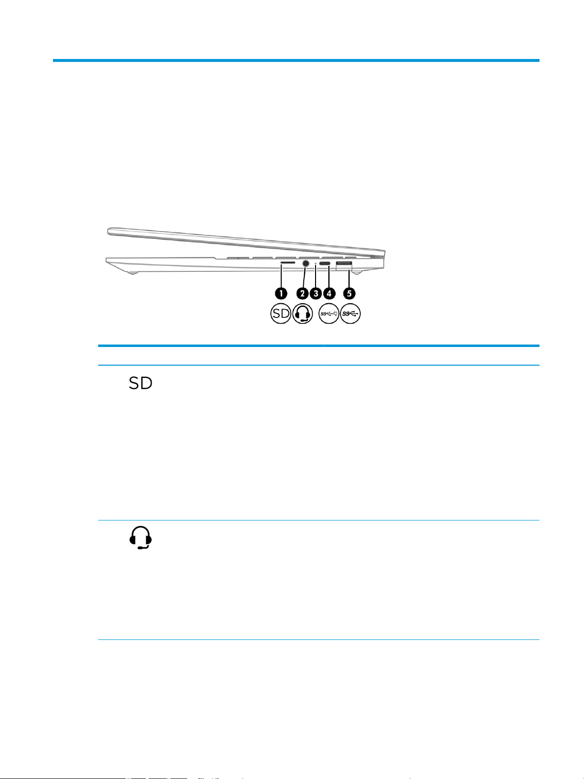
Right side
Use the illustration and table to identify the components on the right side of the computer.
Table 2-1 Right-side components and their descriptions
Component Description
(1) Memory card reader Reads optional memory cards that enable you to store, manage,
share, or access information.
To insert a card:
1. Hold the card label-side up, with connectors facing the
computer.
2. Insert the card into the memory card reader, and then
press in on the card until it is rmly seated.
To remove a card:
▲ Press in on the card, and then remove it from the memory
card reader.
(2) Audio-out (headphone)/Audio-in (microphone)
combo jack
(3) AC adapter and battery light ● White: The AC adapter is connected and the battery is fully
Connects optional powered stereo speakers, headphones,
earbuds, a headset, or a television audio cable. Also connects an
optional headset microphone. This jack does not support
optional standalone microphones.
WARNING! To reduce the risk of personal injury, adjust the
volume before putting on headphones, earbuds, or a headset.
For additional safety information, see the Regulatory, Safety,
and Environmental Notices.
NOTE: When a device is connected to the jack, the computer
speakers are disabled.
charged.
● Amber: The AC adapter is connected and the battery is
charging.
5
Page 14
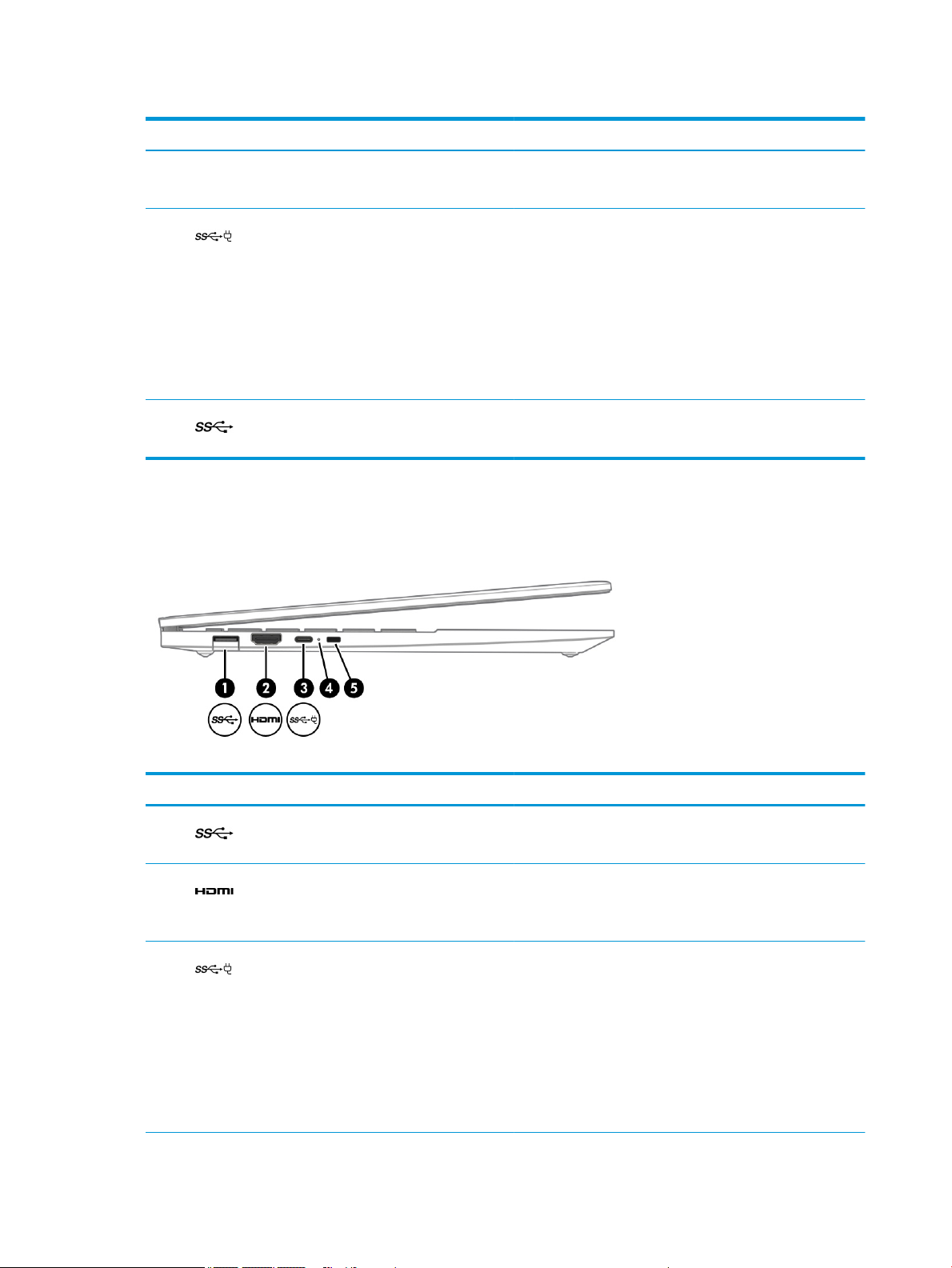
Table 2-1 Right-side components and their descriptions (continued)
Component Description
● Blinking amber: The battery has an error.
● O: The battery is not charging.
(4) USB Type-C power connector and SuperSpeed
(5) USB SuperSpeed port Connects a USB device, such as a cell phone, camera, activity
Left side
Use the illustration and table to identify the components on the left side of the computer.
Plus port
Connects an AC adapter that has a USB Type-C connector,
supplying power to the computer and, if needed, charging the
computer battery.
- and -
Connects a USB device, provides high-speed data transfer, and
(for select products) charges small devices when the computer
is on or in Sleep mode.
NOTE: Cables, adapters, or both (purchased separately) might
be required.
tracker, or smartwatch, and provides high-speed data transfer.
Table
2-2 Left-side components and their descriptions
Component Description
(1) USB SuperSpeed port Connects a USB device, such as a cell phone, camera, activity
(2) HDMI port Connects an optional video or audio device, such as a high-
(3) USB Type-C power connector and SuperSpeed
6 Chapter 2 Components
Plus port
tracker, or smartwatch, and provides high-speed data transfer.
denition television, any compatible digital or audio component,
or a high-speed High Denition Multimedia Interface (HDMI)
device.
Connects an AC adapter that has a USB Type-C connector,
supplying power to the computer and, if needed, charging the
computer battery.
- and -
Connects a USB device, provides high-speed data transfer, and
(for select products) charges small devices when the computer
is on or in Sleep mode.
NOTE: Cables, adapters, or both (purchased separately) might
be required.
Page 15
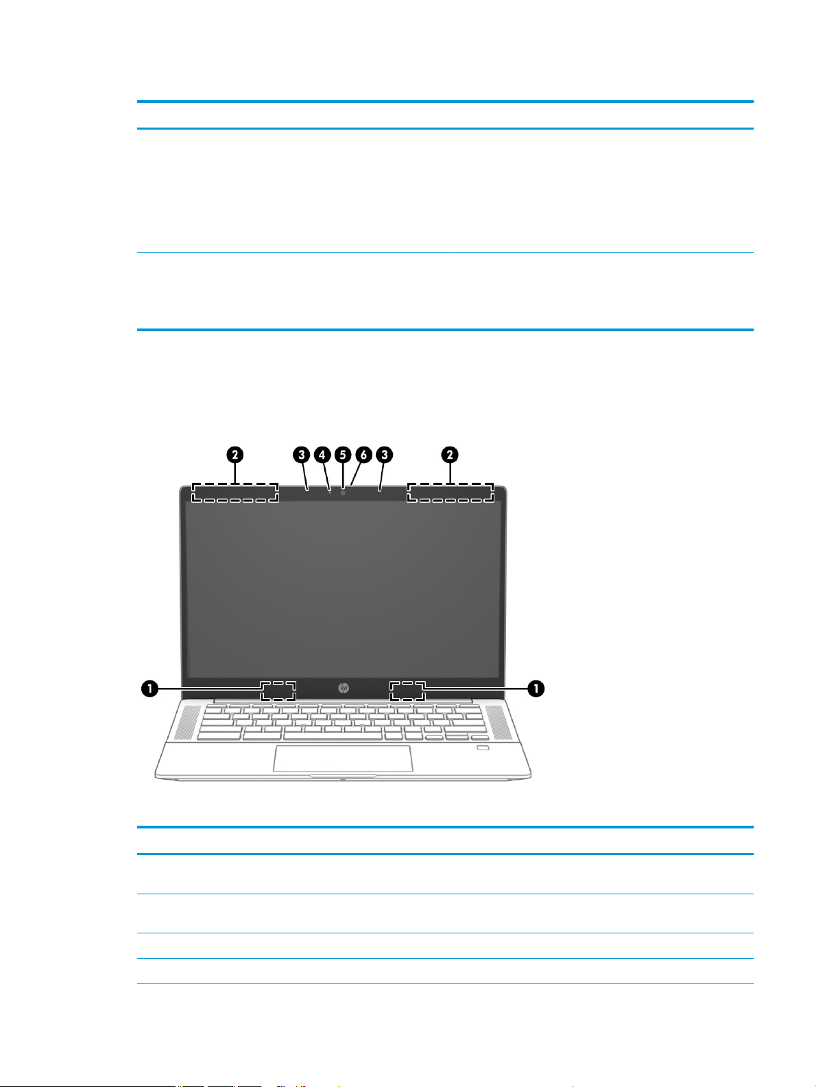
Table 2-2 Left-side components and their descriptions (continued)
Component Description
Display
The computer display can include essential components such as antennas, cameras, and microphones.
(4) AC adapter and battery light ● White: The AC adapter is connected and the battery is fully
charged.
● Amber: The AC adapter is connected and the battery is
charging.
● Blinking amber: The battery has an error.
● O: The battery is not charging.
(5) Security cable slot Attaches an optional security cable to the computer.
NOTE: The security cable is designed to act as a deterrent, but
it might not prevent the computer from being mishandled or
stolen.
Table 2-3 Display components and their descriptions
Component Description
(1) WLAN antennas* Send and receive wireless signals to communicate with wireless local
area networks (WLANs).
(2) WWAN antennas* Send and receive wireless signals to communicate with wireless wide
area networks (WWANs).
(3) Internal microphones Record sound.
(4) Camera light(s) On: One or more cameras are in use.
Display 7
Page 16
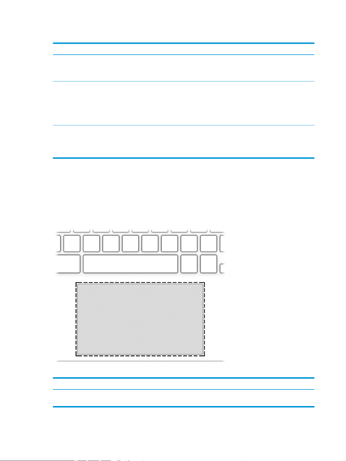
Table 2-3 Display components and their descriptions (continued)
Component Description
(5) Camera(s) Allows(s) you to video chat, record video, and record still images.
(6) Camera privacy cover By default, the camera lens is uncovered, but you can slide the
*The antennas are not visible from the outside of the computer. For optimal transmission, keep the areas immediately around the
antennas free from obstructions.
For wireless regulatory notices, see the section of the Regulatory, Safety, and Environmental Notices that applies to your country or
region.
Keyboard area
Keyboards can vary by language.
NOTE: Camera functions vary depending on the camera hardware
and software installed on your product.
camera privacy cover to block the camera's view. To use the camera,
slide the camera privacy cover in the opposite direction to reveal the
lens.
NOTE: If you have both front-facing and rear-facing cameras, when
one camera lens is revealed and ready to use, the other is concealed.
Touchpad
Identify the touchpad component.
Table
2-4 Touchpad component and description
Component Description
Touchpad zone Reads your nger gestures to move the pointer or activate items on the
8 Chapter 2 Components
screen.
Page 17
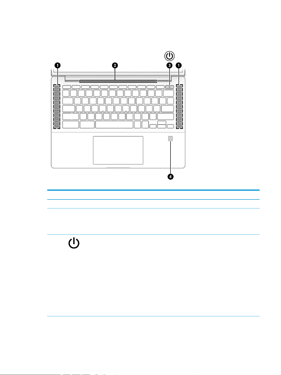
Button, speakers and ngerprint reader
Identify the button, speakers, and ngerprint reader.
Table 2-5 Button, speakers, and ngerprint reader and their descriptions
Component Description
(1) Speakers Produce sound.
(2) Vent Enables airow to cool internal components.
NOTE: The computer fan starts up automatically to cool
internal components and prevent overheating. It is normal for
the internal fan to cycle on and o during routine operation.
(3) Power button ● When the computer is o, press the button briey to
turn on the computer.
● When the computer is on, press the button briey to
initiate Sleep.
● When the computer is in the Sleep state, press the
button briey to exit Sleep (select products only).
● When the computer is in Hibernation, press the button
briey to exit Hibernation.
IMPORTANT: Pressing and holding down the power button
results in the loss of unsaved information.
If the computer has stopped responding and shutdown
procedures are ineective, press and hold the power button
for at least 4 seconds to turn o the computer.
(4) Fingerprint reader (select products only) Allows a ngerprint logon instead of a password logon.
▲ Swipe down across the ngerprint reader for details.
Keyboard area 9
Page 18
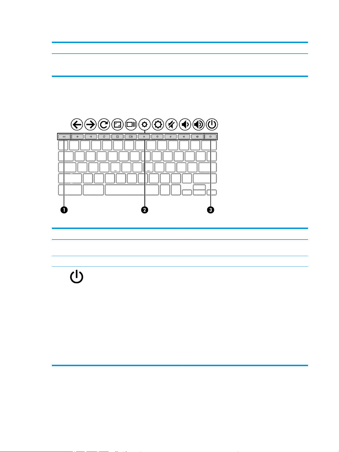
Table 2-5 Button, speakers, and ngerprint reader and their descriptions (continued)
Component Description
Special keys
Identify the special keys.
IMPORTANT: To prevent ngerprint logon issues, be sure
that when you register your ngerprint that all sides of your
nger are registered by the ngerprint reader.
Table 2-6 Special keys and their descriptions
Component Description
(1) esc key Activates certain computer functions when pressed in
(2) Action keys Execute frequently used system functions.
(3) Power button ● When the computer is o, press the button briey to turn
Bottom
combination with other keys, such as tab or shift.
on the computer.
● When the computer is on, press the button briey to
initiate Sleep.
● When the computer is in the Sleep state, press the button
briey to exit Sleep (select products only).
● When the computer is in Hibernation, press the button
briey to exit Hibernation.
IMPORTANT: Pressing and holding down the power button
results in the loss of unsaved information.
If the computer has stopped responding and shutdown
procedures are ineective, press and hold the power button for
at least 4 seconds to turn o the computer.
Identify the bottom component.
10 Chapter 2 Components
Page 19
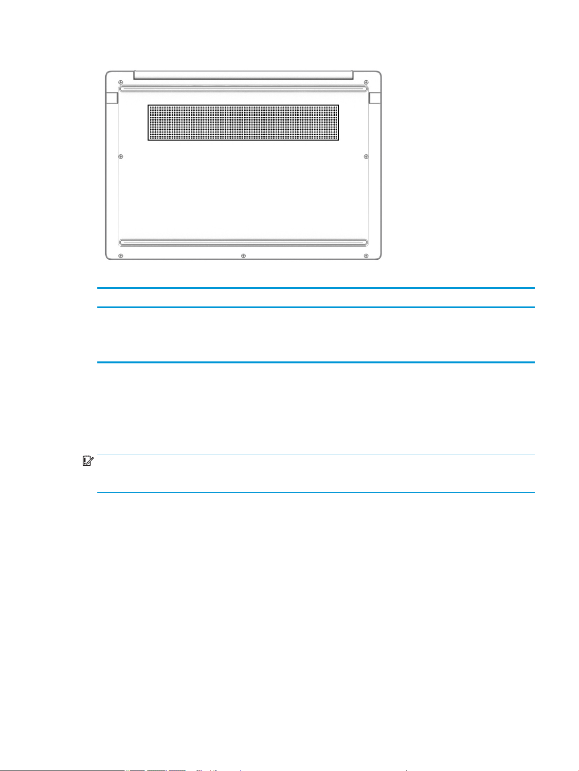
Labels
Table 2-7 Bottom component and description
Component Description
Vent Enables airow airow to cool internal components.
NOTE: The computer fan starts up automatically to cool internal
components and prevent overheating. It is normal for the internal fan to
cycle on and o during routine operation.
The labels axed to the computer provide information you may need when you troubleshoot system
problems or travel internationally with the computer. Labels may be in paper form or imprinted on the
product.
IMPORTANT: Check the following locations for the labels described in this section: the bottom of the
computer, inside the battery bay, under the service door, on the back of the display, or on the bottom of a
tablet kickstand.
● Service label—Provides important information to identify your computer. When contacting support, you
may be asked for the serial number, the product number, or the model number. Locate this information
before you contact support.
Your service label information order may vary by country and might not include the wording "Model" due
to the country regulation.
Labels 11
Page 20
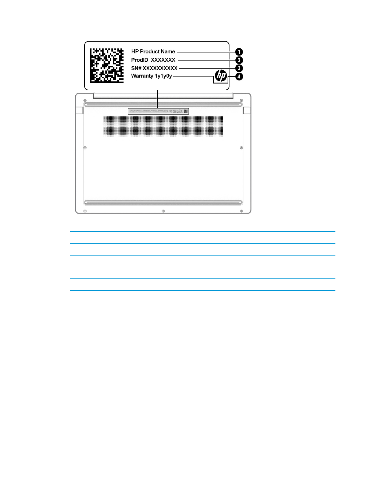
Table 2-8 Service label components
Component
(1) HP product name
(2) Product ID
(3) Serial number
(4) Warranty period
● Regulatory label(s)—Provide(s) regulatory information about the computer.
● Wireless certication label(s)—Provide(s) information about optional wireless devices and the approval
markings for the countries or regions in which the devices have been approved for use.
12 Chapter 2 Components
Page 21
3 Illustrated parts catalog
Use this table to determine the spare parts that are available for the computer.
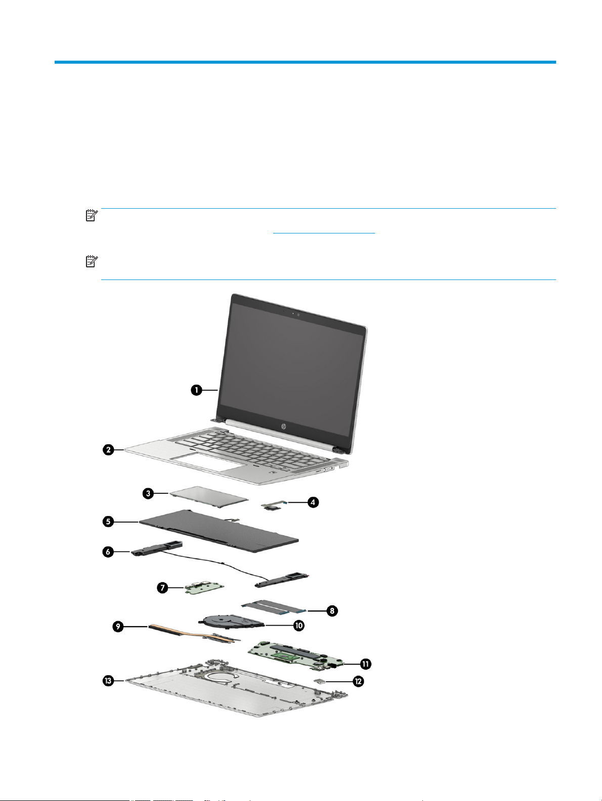
Computer major components
To identify the computer major components, use this illustration and table.
NOTE: HP continually improves and changes product parts. For complete and current information about
supported parts for your computer, go to http://partsurfer.hp.com, select your country or region, and then
follow the on-screen instructions.
NOTE: Details about your computer, including model, serial number, product key, and length of warranty,
are on the service tag at the bottom of your computer.
Computer major components 13
Page 22

Table 3-1 Computer major component descriptions and part numbers
Item Component Spare part number
(1) Display assembly
NOTE: Display assemblies are spared only at the subcomponent level.
(2) Top cover with keyboard
3-coat paint, backlit, with ngerprint sensor M03451-xx1
3-coat paint, backlit, without ngerprint sensor M03452-xx1
Textured, not backlit, without ngerprint sensor M03453-xx1
Textured, not backlit, with ngerprint sensor M03454-xx1
(3) Touchpad (includes rubber)
NOTE: The touchpad cable is available in the Cable Kit as spare part number M00703-001.
(4) Fingerprint sensor board (includes cable) M00438-001
(5) Battery (3 cell, 60 Whr) L84398-002
(6) Speaker Kit M00436-001
(7) USB board M00433-001
(8) USB cables (included in Cable Kit) M00703-001
(9) Heat sink M00434-001
(10) Fan M02014-001
(11) System board (includes integrated processor, system memory, and eMMC memory; includes
replacement thermal material)
Intel Core i7-10610U processor, 16 GB of system memory, and 128 GB of eMMC memory (models
with a ngerprint sensor)
Intel Core i7-10610U processor, 16 GB of system memory, and 64 GB of eMMC memory (models
with a ngerprint sensor)
Intel Core i5-10310U processor, 16 GB of system memory, and 128 GB of eMMC memory (models
with a ngerprint sensor)
Intel Core i5-10310U processor, 16 GB of system memory, and 64 GB of eMMC memory (models
with a ngerprint sensor)
M00437-001
M00695-001
M00694-001
M00691-001
M00690-001
Intel Core i5-10310U processor, 8 GB of system memory, and 64 GB of eMMC memory (models with
a ngerprint sensor)
Intel Core i3-10110U processor, 8 GB of system memory, and 64 GB of eMMC memory (models with
a ngerprint sensor)
Intel Pentium 6405U processor, 8 GB of system memory, and 32 GB of eMMC memory (models
without a ngerprint sensor)
Intel Pentium 6405U processor, 8 GB of system memory, and 32 GB of eMMC memory (models with
a ngerprint sensor)
(12) USB door
Left door M00444-001
14 Chapter 3 Illustrated parts catalog
M00687-001
M00685-001
M00696-001
M00698-001
Page 23
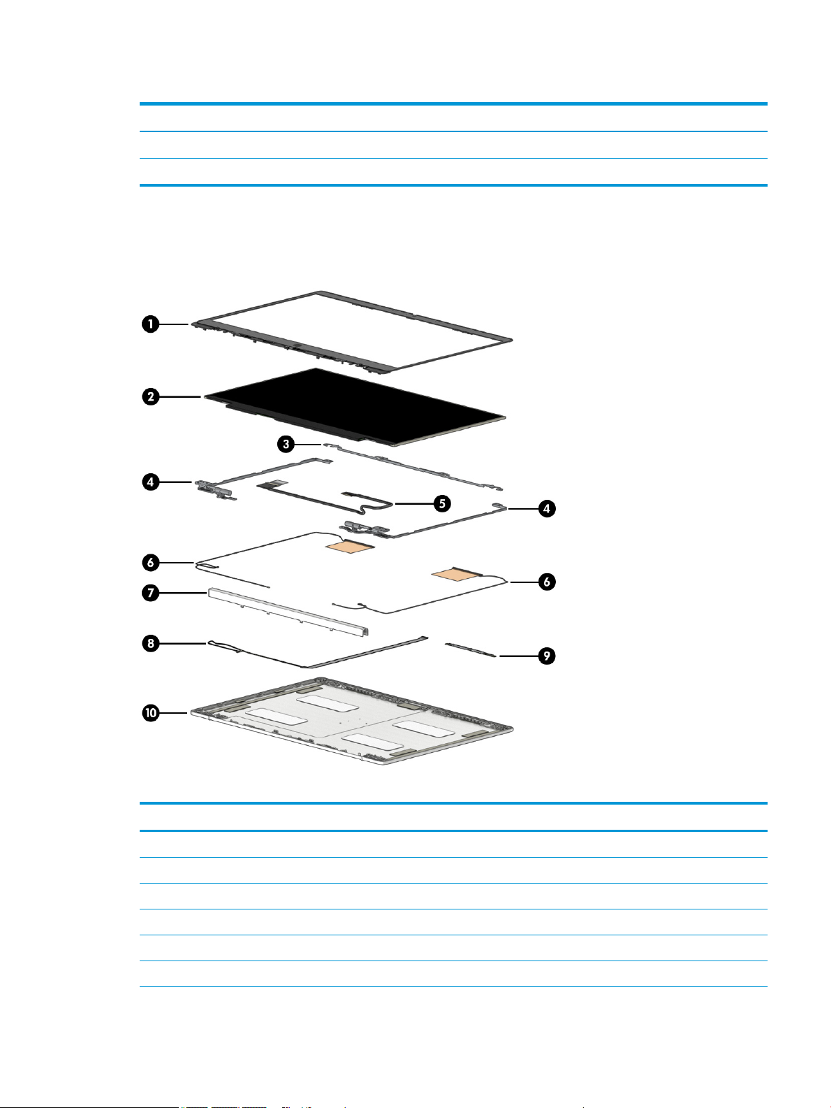
Table 3-1 Computer major component descriptions and part numbers (continued)
Item Component Spare part number
Right door M00445-001
(13) Bottom cover M00432-001
Display assembly subcomponents
To identify the display assembly subcomponents, use this illustration and table.
Table 3-2 Display component descriptions and part numbers
Item Component Spare part number
(1) Display bezel M00701-001
(2) Display panel
FHD, nontouch M00446-001
FHD, touch M00447-001
HD, nontouch M00448-001
HD, touch M00449-001
Display assembly subcomponents 15
Page 24

Cables
Table 3-2 Display component descriptions and part numbers (continued)
Item Component Spare part number
(3) Top bracket M00700-001
(4) Hinges (left and right) M00440-001
(5) Display cable M00702-001
(6) Wireless antennas M00435-001
(7) Hinge cover M00441-001
(8) Camera cable M12614-001
(9) Camera module M00442-001
(10) Display back cover M00439-001
To identify the cables, use this illustration and table.
Table 3-3 Cable descriptions and part numbers
Item Component Spare part number
Cable Kit, includes: M00703-001
(1) Touchpad cable
(2) USB board cable
(3) USB board cable
Miscellaneous parts
To identify the miscellaneous parts, use this table.
16 Chapter 3 Illustrated parts catalog
Page 25

Table 3-4 Miscellaneous part descriptions and part numbers
Component Spare part number
AC adapter, USB Type-C (nPFC, 1.8 m)
65 W L67440-001
45 W L43407-001
Screw Kit M00443-001
Bracket Kit (includes touchpad support bracket and ngerprint bracket) M12524-001
Power cord (C5, 1.0 m)
Australia L19358-001
Brazil L19359-001
Denmark L19360-001
Europe (Austria, Belgium, Finland, France, Germany, the Netherlands, Norway, and Sweden) L19361-001
India L19363-001
Israel L19362-001
Italy L19364-001
Japan L19365-001
North America L19367-001
People's Republic of China L19368-001
South Africa L19369-001
South Korea L19366-001
Switzerland L19370-001
Taiwan L19372-001
Thailand L19371-001
The United Kingdom L19373-001
Power cord (C5, 1.8 m)
Australia L19358-002
Brazil L19359-002
Denmark L19360-002
Europe (Austria, Belgium, Finland, France, Germany, the Netherlands, Norway, and Sweden) L19361-002
India L19363-002
Israel L19362-002
Italy L19364-002
Japan L19365-002
North America L19367-002
People's Republic of China L19368-002
Miscellaneous parts 17
Page 26

Table 3-4 Miscellaneous part descriptions and part numbers (continued)
Component Spare part number
South Africa L19369-002
South Korea L19366-002
Switzerland L19370-002
Taiwan L19372-002
Thailand L19371-002
The United Kingdom L19373-002
18 Chapter 3 Illustrated parts catalog
Page 27

4 Removal and replacement procedures
preliminary requirements
Use this information to properly prepare to disassemble and reassemble the computer.
Tools required
You need the following tools to complete the removal and replacement procedures:
● Tweezers
● Nonconductive, nonmarking pry tool
● Magnetic Phillips P1 screwdriver
Service considerations
The following sections include some of the considerations that you must keep in mind during disassembly
and assembly procedures.
NOTE: As you remove each subassembly from the computer, place the subassembly (and all accompanying
screws) away from the work area to prevent damage.
Plastic parts
Using excessive force during disassembly and reassembly can damage plastic parts.
Cables and connectors
Handle cables with extreme care to avoid damage.
IMPORTANT: When servicing the computer, be sure that cables are placed in their proper locations during
the reassembly process. Improper cable placement can damage the computer.
Apply only the tension required to unseat or seat the cables during removal and insertion. Handle cables by
the connector whenever possible. In all cases, avoid bending, twisting, or tearing cables. Be sure that cables
are routed so that they cannot be caught or snagged as you remove or replace parts. Handle ex cables with
extreme care; these cables tear easily.
Drive handling
Note the following guidelines when handling drives.
Tools required 19
Page 28

IMPORTANT: Drives are fragile components. Handle them with care. To prevent damage to the computer,
damage to a drive, or loss of information, observe these precautions:
Before removing or inserting a hard drive, shut down the computer. If you are unsure whether the computer is
o or in Hibernation, turn the computer on, and then shut it down through the operating system.
Before handling a drive, be sure that you are discharged of static electricity. While handling a drive, avoid
touching the connector.
Before removing an optical drive, be sure that a disc is not in the drive, and be sure that the optical drive tray
is closed.
Handle drives on surfaces covered with at least 2.54 cm (1 inch) of shock-proof foam.
Avoid dropping drives from any height onto any surface.
After removing a hard drive or an optical drive, place it in a static-proof bag.
Avoid exposing an internal hard drive to products that have magnetic elds, such as monitors or speakers.
Avoid exposing a drive to temperature extremes or liquids.
If a drive must be mailed, place the drive in a bubble pack mailer or other suitable form of protective
packaging, and label the package “FRAGILE.”
Workstation guidelines
Follow these grounding workstation guidelines:
● Cover the workstation with approved static-shielding material.
● Use a wrist strap connected to a properly grounded work surface and use properly grounded tools and
equipment.
● Use conductive eld service tools, such as cutters, screw drivers, and vacuums.
● When xtures must directly contact dissipative surfaces, use xtures made only of static-safe materials.
● Keep the work area free of nonconductive materials, such as ordinary plastic assembly aids
and polystyrene foam.
● Handle ESD-sensitive components, parts, and assemblies by the case or PCM laminate. Handle these
items only at static-free workstations.
● Avoid contact with pins, leads, or circuitry.
● Turn o power and input signals before inserting or removing connectors or test equipment.
Electrostatic discharge information
A sudden discharge of static electricity from your nger or other conductor can destroy static-sensitive
devices or microcircuitry. Often the spark is neither felt nor heard, but damage occurs. An electronic device
exposed to electrostatic discharge (ESD) might not appear to be aected at all and can work perfectly
throughout a normal cycle. The device might function normally for a while, but it has been degraded in the
internal layers, reducing its life expectancy.
Networks built into many integrated circuits provide some protection, but in many cases, the discharge
contains enough power to alter device parameters or melt silicon junctions.
20 Chapter 4 Removal and replacement procedures preliminary requirements
Page 29

IMPORTANT: To prevent damage to the device when you remove or install internal components, observe
these precautions:
Keep components in their electrostatic-safe containers until you are ready to install them.
Before touching an electronic component, discharge static electricity by using the guidelines described
Personal grounding methods and equipment on page 22.
Avoid touching pins, leads, and circuitry. Handle electronic components as little as possible.
If you remove a component, place it in an electrostatic-safe container.
Generating static electricity
Follow these static electricity guidelines.
● Dierent activities generate dierent amounts of static electricity.
● Static electricity increases as humidity decreases.
Table 4-1 Static electricity occurrence based on activity and humidity
Event 55% 40% 10%
Relative humidity
Walking across carpet
Walking across vinyl oor
Motions of bench worker
Removing DIPs (dual in-line packages) from plastic tube
Removing DIPs from vinyl tray
Removing DIPs from polystyrene foam
Removing bubble pack from PCB (printed circuit board)
Packing PCBs in foam-lined box
Multiple electric components can be packaged together in plastic tubes, trays, or polystyrene foam.
NOTE: As little as 700 V can degrade a product.
Preventing electrostatic damage to equipment
Many electronic components are sensitive to ESD. Circuitry design and structure determine the degree of
sensitivity. The following packaging and grounding precautions are necessary to prevent static electricity
damage to electronic components.
● To avoid hand contact, transport products in static-safe containers such as tubes, bags, or boxes.
7,500 V
3,000 V
400 V
400 V
2,000 V
3,500 V
7,000 V
5,000 V
15,000 V
5,000 V
800 V
700 V
4,000 V
5,000 V
20,000 V
11,000 V
35,000 V
12,000 V
6,000 V
2,000 V
11,500 V
14,500 V
26,500 V
21,000 V
● Protect all electrostatic parts and assemblies with conductive or approved containers or packaging.
● Keep electrostatic-sensitive parts in their containers until they arrive at static-free stations.
● Place items on a grounded surface before removing them from their container.
● Always be properly grounded when touching a sensitive component or assembly.
Electrostatic discharge information 21
Page 30

● Avoid contact with pins, leads, or circuitry.
● Place reusable electrostatic-sensitive parts from assemblies in protective packaging or conductive
foam.
Personal grounding methods and equipment
Using certain equipment can prevent static electricity damage to electronic components.
● Wrist straps are exible straps with a maximum of 1 MΩ ±10% resistance in the ground cords. To
provide proper ground, a strap must be worn snug against bare skin. The ground cord must be
connected and t snugly into the banana plug connector on the grounding mat or workstation.
● Heel straps/Toe straps/Boot straps can be used at standing workstations and are compatible with
most types of shoes or boots. On conductive oors or dissipative oor mats, use them on both feet with
a maximum of 1 MΩ ±10% resistance between the operator and ground.
Table 4-2 Static shielding protection levels
Static shielding protection levels
Method Voltage
Antistatic plastic
Carbon-loaded plastic
Metallized laminate
Grounding the work area
To prevent static damage at the work area, follow these precautions.
● Cover the work surface with approved static-dissipative material. Provide a wrist strap connected to the
work surface and properly grounded tools and equipment.
● Use static-dissipative mats, foot straps, or air ionizers to give added protection.
● Handle electrostatic sensitive components, parts, and assemblies by the case or PCB laminate. Handle
them only at static-free work areas.
● Turn o power and input signals before inserting and removing connectors or test equipment.
● Use xtures made of static-safe materials when xtures must directly contact dissipative surfaces.
● Keep work area free of nonconductive materials such as ordinary plastic assembly aids and polystyrene
foam.
● Use eld service tools, such as cutters, screwdrivers, and vacuums, that are conductive.
Recommended materials and equipment
1,500
7,500
15,000
HP recommends certain materials and equipment to prevent static electricity.
● Antistatic tape
● Antistatic smocks, aprons, or sleeve protectors
● Conductive bins and other assembly or soldering aids
● Conductive foam
● Conductive tabletop workstations with ground cord of 1 MΩ ±10% resistance
22 Chapter 4 Removal and replacement procedures preliminary requirements
Page 31

● Static-dissipative table or oor mats with hard tie to ground
● Field service kits
● Static awareness labels
● Wrist straps and footwear straps providing 1 MΩ ±10% resistance
● Material handling packages
● Conductive plastic bags
● Conductive plastic tubes
● Conductive tote boxes
● Opaque shielding bags
● Transparent metallized shielding bags
● Transparent shielding tubes
Packaging and transporting guidelines
Follow these grounding guidelines when packaging and transporting equipment.
● To avoid hand contact, transport products in static-safe tubes, bags, or boxes.
● Protect ESD-sensitive parts and assemblies with conductive or approved containers or packaging.
● Keep ESD-sensitive parts in their containers until the parts arrive at static-free workstations.
● Place items on a grounded surface before removing items from their containers.
● Always be properly grounded when touching a component or assembly.
● Store reusable ESD-sensitive parts from assemblies in protective packaging or nonconductive foam.
● Use transporters and conveyors made of antistatic belts and roller bushings. Be sure that mechanized
equipment used for moving materials is wired to ground and that proper materials are selected to avoid
static charging. When grounding is not possible, use an ionizer to dissipate electric charges.
Packaging and transporting guidelines 23
Page 32

24 Chapter 4 Removal and replacement procedures preliminary requirements
Page 33

5 Removal and replacement procedures for
authorized service provider parts
This chapter provides removal and replacement procedures for authorized service provider parts.
IMPORTANT: Components described in this chapter should be accessed only by an authorized service
provider. Accessing these parts can damage the computer or void the warranty.
NOTE: Details about your computer, including model, serial number, product key, and length of warranty,
are on the service tag at the bottom of your computer.
Component replacement procedures
To remove and replace computer components, use these procedures.
NOTE: HP continually improves and changes product parts. For complete and current information about
supported parts for your computer, go to http://partsurfer.hp.com, select your country or region, and then
follow the on-screen instructions.
You must remove, replace, or loosen as many as 50 screws when you service the parts described in this
chapter. Make special note of each screw size and location during removal and replacement.
Preparation for disassembly
To remove and replace computer components, use these procedures.
See Removal and replacement procedures preliminary requirements on page 19 for initial safety procedures.
1. Turn o the computer. If you are unsure whether the computer is o or in Hibernation, turn the
computer on, and then shut it down through the operating system.
2. Disconnect the power from the computer by unplugging the power cord from the computer.
3. Disconnect all external devices from the computer.
Bottom cover
To remove the bottom cover, use this procedure and illustration.
Table
5-1 Bottom cover description and part number
Description Spare part number
Bottom cover M00432-001
Before removing the bottom cover, prepare the computer for disassembly (Preparation for disassembly
on page 25).
Remove the bottom cover:
1. Remove the four Phillips M2.0 × 7.0 screws (1) from the sides and top and the three Phillips M2.0 × 3.5
screws (2) from the bottom that secure the bottom cover to the computer.
25
Page 34

2. Use a nonmarking, nonconductive tool (1) to release the edges of the bottom cover from the computer
(2).
3. Remove the bottom cover from the computer (3).
To replace the bottom cover, reverse the removal procedures.
Battery
To remove the battery, use this procedure and illustration.
5-2 Battery description and part number
Table
Description Spare part number
Battery (3 cell, 60 Whr) L84398-002
26 Chapter 5 Removal and replacement procedures for authorized service provider parts
Page 35

WARNING! To avoid personal injury and damage to the product:
● Do not puncture, twist, or crack the battery.
● Do not cause an external puncture or rupture to the battery. They can cause a short inside the battery,
which can result in battery thermal runaway.
● Do not handle or touch the battery enclosure with sharp objects such as tweezers or pliers, which might
puncture the battery.
● Do not compress or squeeze the battery case with tools or heavy objects stacked on top of the case.
These actions can apply undue force on the battery.
● Do not touch the connectors with any metallic surface or object, such as metal tools, screws, or coins,
which can cause shorting across the connectors.
Before removing the battery, follow these steps:
1. Prepare the computer for disassembly (Preparation for disassembly on page 25).
2. Remove the bottom cover (Bottom cover on page 25).
WARNING! To reduce potential safety issues, use only the user-replaceable battery provided with the
computer, a replacement battery provided by HP, or a compatible battery purchased from HP.
IMPORTANT: Removing a battery that is the sole power source for the computer can cause loss of
information. To prevent loss of information, save your work or shut down the computer through Windows
before you remove the battery.
Remove the battery:
1. Disconnect the battery cable from the system board (1).
2. Remove the ve Phillips M2.0 × 3.0 screws (2) that secure the battery to the computer.
Component replacement procedures 27
Page 36

3. Remove the battery from the computer (3).
To insert the battery, reverse the removal procedures.
Speakers
To remove the speakers, use this procedure and illustration.
Table
Before removing the speakers, follow these steps:
1. Prepare the computer for disassembly (Preparation for disassembly on page 25).
2. Remove the bottom cover (Bottom cover on page 25).
3. Remove the battery (see Battery on page 26).
Remove the speakers:
1. Disconnect the speaker cable from the system board (1).
2. Disconnect the cable from the ZIF connector on the touchpad (2). You need to move this cable so you can
5-3 Speaker description and part number
Description Spare part number
Speaker Kit M00436-001
remove the speaker cable that routes under it.
28 Chapter 5 Removal and replacement procedures for authorized service provider parts
Page 37

3. Lift the tape that secures the speaker cable to the touchpad (3).
4. Remove the speaker cable from the clips in the computer chassis (4).
5. Remove the two Phillips M2.0 × 5.0 screws (5) that secure the speakers to the computer.
NOTE: When installing the speakers, be sure that the gaskets are correctly installed in the speaker
screw holes (6).
6. Remove the speakers from the computer (7) .
Reverse this procedure to install the speakers.
Touchpad
To remove the touchpad, use this procedure and illustration.
Table
Before removing the touchpad, follow these steps:
1. Prepare the computer for disassembly (Preparation for disassembly on page 25).
2. Remove the bottom cover (Bottom cover on page 25).
3. Remove the battery (see Battery on page 26).
5-4 Touchpad description and part number
Description Spare part number
Touchpad M00437-001
Touchpad cable (included in Cable Kit) M00703-001
Touchpad support bracket (included in Bracket Kit) M12524-001
Component replacement procedures 29
Page 38

Remove the touchpad:
1. Remove the four Phillips M2.0 × 2.5 screws (1) that secure the touchpad bracket to the computer.
2. Remove the touchpad bracket from the computer (2).
3. Lift the tape that secures the speaker cable to the touchpad (1).
4. Disconnect the cable from the ZIF connector on the touchpad (2).
5. Remove the protective shielding from the top of the touchpad (3).
6. Remove the three Phillips M2.0 × 2.0 screws (4) that secure the touchpad to the computer.
30 Chapter 5 Removal and replacement procedures for authorized service provider parts
Page 39

7. Remove the touchpad from the computer (5).
Reverse this procedure to install the touchpad.
Fingerprint sensor board
To remove the ngerprint sensor board, use this procedure and illustration.
Table
5-5 Fingerprint sensor board description and part number
Description Spare part number
Fingerprint sensor board M00438-001
Fingerprint sensor bracket (available in the Bracket Kit) M12524-001
Before removing the ngerprint sensor board, follow these steps:
1. Prepare the computer for disassembly (Preparation for disassembly on page 25).
2. Remove the bottom cover (Bottom cover on page 25).
3. Remove the battery (see Battery on page 26).
Remove the ngerprint sensor board:
1. Disconnect the cable from the ZIF connector on the system board (1).
2. Remove the Phillips M2.0 × 2.0 screw (2) that secures the ngerprint sensor bracket, and then remove
the bracket (3).
Component replacement procedures 31
Page 40

3. Remove the ngerprint sensor board from the computer (4).
Reverse this procedure to install the ngerprint sensor board.
Fan
To remove the fan, use this procedure and illustration.
Table
5-6 Fan description and part number
Description Spare part number
Fan assembly M02014-001
Before removing the fan, follow these steps:
1. Prepare the computer for disassembly (Preparation for disassembly on page 25).
2. Remove the bottom cover (Bottom cover on page 25).
3. Remove the battery (see Battery on page 26).
Remove the fan assembly:
1. Disconnect the fan cable from the system board (1).
32 Chapter 5 Removal and replacement procedures for authorized service provider parts
Page 41

2. Remove the three Phillips M2.0 × 3.0 screws (2), and then remove the fan (3).
Reverse this procedure to install the fan assembly.
Heat sink
To remove the heat sink, use these procedures and illustrations.
Table
5-7 Heat sink descriptions and part numbers
Description Spare part number
Heat sink M00434-001
Before removing the heat sink, follow these steps:
1. Prepare the computer for disassembly (Preparation for disassembly on page 25).
2. Remove the bottom cover (Bottom cover on page 25).
3. Remove the battery (see Battery on page 26).
Remove the heat sink:
1. In the order indicated on the heat sink, remove the four Phillips M2.0 × 2.0 screws (1), and then remove
the heat sink from the computer (2).
Component replacement procedures 33
Page 42

2. Thoroughly clean the thermal material from the surfaces of the heat sink and the system board
components each time the heat sink is removed. Replacement thermal material is included with the heat
sink and system board spare part kits. The following illustration shows the replacement thermal
material locations.
Thermal paste is used on one system board component (1) and on the heat sink area (2) that services it.
Reverse this procedure to install the heat sink.
34 Chapter 5 Removal and replacement procedures for authorized service provider parts
Page 43

USB board
To remove the USB board, use this procedure and illustration.
Table 5-8 USB board description and part number
Description Spare part number
USB board M00433-001
USB board cables (included in Cable Kit) M00703-001
Before removing the USB board, follow these steps:
1. Prepare the computer for disassembly (Preparation for disassembly on page 25).
2. Remove the bottom cover (Bottom cover on page 25).
3. Remove the battery (see Battery on page 26).
Remove the USB board:
1. Disconnect the two cables from the ZIF connectors on the USB board (1).
2. Remove the ve Phillips M2.0 × 3.0 screws (2) that secure the board to the computer.
3. Remove the board from the computer (3).
Reverse this procedure to install the USB board.
USB door
To remove the USB door, use this procedure and illustration.
Component replacement procedures 35
Page 44

Table 5-9 USB door description and part number
Description Spare part number
USB door, left M00444-001
USB door, right M00445-001
Before removing the USB door, follow these steps:
1. Prepare the computer for disassembly (Preparation for disassembly on page 25).
2. Remove the bottom cover (Bottom cover on page 25).
3. Remove the battery (see Battery on page 26).
Remove the USB door:
1. Insert a removal tool (1) under the USB door (2).
2. Align the posts on the tool with the slots on the underside of the door (3), and then pull the tool away
from the door to release it (4).
36 Chapter 5 Removal and replacement procedures for authorized service provider parts
Page 45

3. Remove the USB door from the computer (5).
USB doors are available for both sides of the computer.
Reverse this procedure to install the USB door.
Component replacement procedures 37
Page 46

System board
To remove the system board, use these procedures and illustrations.
Table 5-10 System board descriptions and part numbers
Description Spare part
number
Intel Core i7-10610U processor, 16 GB of system memory, and 128 GB of eMMC memory (models with a ngerprint
sensor)
Intel Core i7-10610U processor, 16 GB of system memory, and 64 GB of eMMC memory (models with a ngerprint
sensor)
Intel Core i5-10310U processor, 16 GB of system memory, and 128 GB of eMMC memory (models with a ngerprint
sensor)
Intel Core i5-10310U processor, 16 GB of system memory, and 64 GB of eMMC memory (models with a ngerprint
sensor)
Intel Core i5-10310U processor, 8 GB of system memory, and 64 GB of eMMC memory (models with a ngerprint
sensor)
Intel Core i3-10110U processor, 8 GB of system memory, and 64 GB of eMMC memory (models with a ngerprint
sensor)
Intel Pentium 6405U processor, 8 GB of system memory, and 32 GB of eMMC memory (models without a ngerprint
sensor)
Intel Pentium 6405U processor, 8 GB of system memory, and 32 GB of eMMC memory (models with a ngerprint
sensor)
Before removing the system board, follow these steps:
1. Prepare the computer for disassembly (Preparation for disassembly on page 25).
2. Remove the bottom cover (Bottom cover on page 25).
M00695-001
M00694-001
M00691-001
M00690-001
M00687-001
M00685-001
M00696-001
M00698-001
3. Remove the battery (see Battery on page 26).
4. Remove the fan (see Fan on page 32).
Remove the system board:
1. Disconnect the following cables from the system board:
● Antenna cables from integrated WLAN module (1)
● Camera cable (2)
● Display cable (3)
● USB board cable (ZIF) from USB board (4)
● USB board cable (ZIF) from USB board (5)
● Keyboard backlight cable (ZIF) (6) (select products only)
● Touchpad cable (ZIF) (7)
● Keyboard cable (ZIF) (8)
38 Chapter 5 Removal and replacement procedures for authorized service provider parts
Page 47

● Fingerprint reader cable (ZIF) (9)
● Speaker cable (10)
2. Remove the four Phillips M2.0 × 5.0 screws that secure the system board to the computer.
Component replacement procedures 39
Page 48

3. Lift the right side of the system board (1), and then pull the board up and to the right to remove it (2).
4. If you need to remove the USB cables from the system board, disconect the bottom (1) and top (2)
cables.
Reverse this procedure to install the system board.
Display assembly
To remove and disassemble the display assembly, use these procedures and illustrations.
Before removing the display panel, follow these steps:
1. Prepare the computer for disassembly (Preparation for disassembly on page 25).
2. Remove the bottom cover (Bottom cover on page 25).
40 Chapter 5 Removal and replacement procedures for authorized service provider parts
Page 49

3. Remove the battery (see Battery on page 26).
4. Remove the heat sink (see Heat sink on page 33).
Remove the display assembly:
1. Disconnect the antennas from the WLAN module (1).
2. Disconnect the camera cable (2).
3. Disconnect the display cable (3).
4. Remove the four Phillips M2.5 × 5.0 screws (1) that secure the display to the computer.
5. Open the computer to open the hinges (2).
Component replacement procedures 41
Page 50

6. Separate the computer from the display (3).
7. If you need to replace display assembly subcomponents:
a. Remove the three Phillips M2.0 × 3.0 screws (1) that secure the bezel to the display.
b. Slide a at tool (2) under each side of the bezel to remove it (3).
The bezel is available as spare part number M00701-001.
42 Chapter 5 Removal and replacement procedures for authorized service provider parts
Page 51

8. If you need to remove the hinge cover, squeeze near both ends of the cover (1), and then pull the cover
o the hinges (2).
The hinge cover is available as spare part number M00441-001.
9. If you need to remove the display panel:
a. Lift the bottom of the panel (1).
b. The display panel is secured to the display enclosure with tape that is installed under the left and
right sides of the panel. To remove the panel, use tweezers to grasp the end of the tape (2). While
turning the tweezers, wrap the tape around the tweezers (3) as you continue to pull the tape out
from behind the display panel (4). You must pull the tape multiple times before it is completely
removed.
Component replacement procedures 43
Page 52

c. Rotate the display panel over and place it next to the display enclosure.
Display panels are available as the following spare part numbers:
M00446-001: FHD, nontouch
M00447-001: FHD, touch
M00448-001: HD, nontouch
M00449-001: HD, touch
d. Disconnect the cable from the panel (1).
e. Remove the panel (2).
44 Chapter 5 Removal and replacement procedures for authorized service provider parts
Page 53

10. If you need to remove the display cable:
▲ Remove the cable from the right hinge and along the bottom of the display back cover. The display
cable is available as spare part number M00702-001.
11. If you need to remove the camera module and cable:
a. Use a at tool to lift up evenly across the camera module to remove it from the display back cover
(1), and then remove the cable and module assembly (2).
Component replacement procedures 45
Page 54

b. Lift the latch on the reverse ZIF connector on the camera module (1), and then disconnect the cable
(2). The camera module is available as spare part number M00442-001. The camera cable is
available as spare part number M12614-001.
12. If you need to remove the hinges from the display:
a. Remove the two Phillips broadhead M2.5 × 2.5 screws (1) from each hinge.
b. Remove the hinges from the display (2).
The display hinges are available as spare part number M00440-001.
46 Chapter 5 Removal and replacement procedures for authorized service provider parts
Page 55

13. If you need to remove the top display bracket from the display:
a. Remove the four Phillips broadhead M2.0 × 2.5 screws (1) from the bracket.
b. Remove the bracket from the display (2).
The bracket is available as spare part number M00700-001.
Component replacement procedures 47
Page 56

14. If you need to remove the antenna cables, remove the cables from the clips on the inside of the cover
(1), and then peel the antennas o the cover to remove them (2).
Antenna cables are available as spare part number M00435-001.
The display back cover is available as spare part number M00439-001.
Reverse this procedure to reassemble and replace the display assembly.
Keyboard with top cover
The top cover with keyboard remains after removing all other spare parts from the computer. In this section,
the rst table provides the main spare part number for the top cover/keyboards. The second table provides
the country codes.
Table
5-11 Keyboard with top cover descriptions and part numbers
Description Spare part number
Keyboard with top cover, 3-coat paint, backlit, with ngerprint sensor M03451-xx1
Keyboard with top cover, 3-coat paint, backlit, without ngerprint sensor M03452-xx1
Keyboard with top cover, textured, not backlit, without ngerprint sensor M03453-xx1
Keyboard with top cover, textured, not backlit, with ngerprint sensor M03454-xx1
Table 5-12 Spare part country codes
For use in country or
region
Belgium -A41 Iceland -DD1 Solvenia -BA1
Spare part
number
For use in country or
region
Spare part
number
For use in country or
region
Spare part
number
Brazil -201 India -D61 South Korea -AD1
Bulgaria -261 Israel -BB1 Spain -071
Chile -161 Italy -061 Switzerland -BG1
48 Chapter 5 Removal and replacement procedures for authorized service provider parts
Page 57

Table 5-12 Spare part country codes (continued)
For use in country or
region
Czech Republic/Slovakia -FL1 Japan -291 Taiwan -AB1
Denmark, Finland, and
Norway
French Canada -DB1 Northern Africa -FP1 Turkey -141
France -051 Portugal -131 Ukraine -BD1
Germany -041 Romania -271 United Kingdom -031
Greece -151 Russia -251 United States -001
Hungary -211 Saudi Arabia -171
Spare part
number
-DH1 The Netherlands -B31 Thailand -281
For use in country or
region
Spare part
number
For use in country or
region
Spare part
number
Component replacement procedures 49
Page 58

50 Chapter 5 Removal and replacement procedures for authorized service provider parts
Page 59

6 Backing up, resetting, and recovering
This chapter provides information about processes that are standard procedure for most products.
Backing up
You can back up your data to an optional USB ash drive or SD memory card or through Google Drive.
For detailed information about creating a backup, go to http://www.support.google.com.
Resetting
A factory reset erases all the information on your computer hard drive, including all the les in the Downloads
folder. Before you reset, be sure to back up your les to an optional USB ash drive, SD memory card, or
through Google Drive. The factory reset will not delete any of your les on Google Drive or an external storage
device.
Recovering
When your Chrome OS™ operating system is not working properly, you can perform a recovery. A recovery
reinstalls the operating system and software programs and restores the original factory settings. Locally
saved les and saved networks are deleted for all accounts. Your Google Accounts and any data synced to
your Google Drive™ storage are not aected by a system recovery.
NOTE: For more information about performing a system recovery on your computer, go to
http://www.support.google.com
Before beginning the recovery process, you need the following:
● A USB ash drive or SD memory card with a capacity of 4 GB or greater. All data is erased from this
storage device when the recovery media is created, so back up any les from the device before you
begin.
● A computer with internet access. You must also have administrative rights to the computer.
● Computer AC adapter. The computer must be plugged into AC power during recovery.
● The “Chrome OS is missing or damaged” screen displaying on your computer. If this message is not
already displayed:
– Turn on the computer, press and hold the esc + f3 keys, and then press the power button. The
computer restarts, and the screen shows the “Chrome OS is missing or damaged” screen.
Installing the Chromebook Recovery Utility
The Chromebook™ Recovery Utility is an app used to recover the original operating system and software
programs that were installed at the factory. This utility can be installed from the Chrome Web Store on any
computer.
51
Page 60

Creating recovery media
Recovery media is used to recover the original operating system and software programs that were installed at
the factory.
Recovering the Chrome operating system
To recover the Chrome operating system on your computer using the recovery media you created:
Setting up your computer after a reset or recovery
After a reset or recovery is complete, perform the initial setup process.
For details on setting up the computer, go to http://www.support.google.com.
Erase and reformat the recovery media
During the process of creating recovery media, the USB ash drive or SD memory card is formatted for use as
a recovery tool. After you recover your computer, you will need to erase the recovery media if you want to
reuse your USB ash drive or SD memory card to store other les. Use the steps in this section to erase the
recovery media using the Chromebook Recovery Utility.
52 Chapter 6 Backing up, resetting, and recovering
Page 61

7 Specications
This chapter provides specications for your computer.
Computer specications
This section provides specications for your computer. When traveling with your computer, the computer
dimensions and weights, as well as input power ratings and operating specications, provide helpful
information.
Table 7-1 Computer specications
Dimensions
Width 323.6 mm 12.8 in
Depth 221 mm 8.07 in
Height 16.5 mm 0.65 in
Weight 1.52 kg 3.35 lb
Input power
Metric U.S.
Operating voltage and current 19.5 V dc @ 3.33 A – 65 W
19.5 V dc @ 2.31 A – 45 W
Temperature
Operating 5°C to 35°C 41°F to 95°F
Nonoperating –20°C to 60°C –4°F to 140°F
Relative humidity (noncondensing)
Operating 10% to 90%
Nonoperating 5% to 95%
Maximum altitude (unpressurized)
Operating –15 m to 3,048 m –50 ft to 10,000 ft
Nonoperating –15 m to 12,192 m –50 ft to 40,000 ft
NOTE: Applicable product safety standards specify thermal limits for plastic surfaces. The device operates well within this range of
temperatures.
35.6 cm (14.0 in) display specications
This section provides specications for your display.
Computer specications 53
Page 62

Table 7-2 Display specications
Metric U.S.
Active diagonal size 35.6 cm 14.0 in
Resolution 1920 × 1080 (FHD)
1368 × 766 (HD)
Surface treatment Antiglare (FHD panels)
Brightview (FHD, HD panels)
Brightness 250 nits (FHD panels)
220 nits (HD panels)
Viewing angle UWVA (FHD panels)
SVA (HD panels)
Backlight WLED
Display panel interface eDP
54 Chapter 7 Specications
Page 63

8 Statement of memory volatility
For general information regarding nonvolatile memory in HP Business computers, and to restore nonvolatile
memory that can contain personal data after the system has been turned o and the hard drive has been
removed, use these instructions.
HP Business computer products that use Intel®-based or AMD®-based system boards contain volatile DDR
memory. The amount of nonvolatile memory present in the system depends upon the system
Intel-based and AMD-based system boards contain nonvolatile memory subcomponents as originally shipped
from HP, with the following assumptions:
● No subsequent modications were made to the system.
● No applications, features, or functionality were added to or installed on the system.
Following system shutdown and removal of all power sources from an HP Business computer system,
personal data can remain on volatile system memory (DIMMs) for a nite period of time and also remains in
nonvolatile memory. Use the following steps to remove personal data from the computer, including the
nonvolatile memory found in Intel-based and AMD-based system boards.
NOTE: If your tablet has a keyboard base, connect to the keyboard base before beginning steps in this
chapter.
conguration.
Current BIOS steps
Use these instructions to restore nonvolatile memory.
1. Follow these steps to restore the nonvolatile memory that can contain personal data. Restoring or
reprogramming nonvolatile memory that does not store personal data is neither necessary nor
recommended.
a. Turn on or restart the computer, and then quickly press esc.
NOTE: If the system has a BIOS administrator password, enter the password at the prompt.
b. Select Main, select Apply Factory Defaults and Exit, and then select Yes to load defaults. The
computer restarts.
c. During the restart, press esc while the "Press the ESC key for Startup Menu" message is displayed
at the bottom of the screen.
NOTE: If the system has a BIOS administrator password, enter the password at the prompt.
d. Select the Security menu, select Restore Security Settings to Factory Defaults, and then select
Yes to restore security level defaults. The computer reboots.
e. During the reboot, press esc while the "Press the ESC key for Startup Menu" message is displayed
at the bottom of the screen.
NOTE: If the system has a BIOS administrator password, enter the password at the prompt.
f. If an asset or ownership tag is set, select the Security menu and scroll down to the Utilities menu.
Select System IDs, and then select Asset Tracking Number. Clear the tag, and then make the
selection to return to the prior menu.
55
Page 64

g. If a DriveLock password is set, select the Security menu, and scroll down to Hard Drive Utilities
under the Utilities menu. Select Hard Drive Utilities, select DriveLock, and then clear the check
box for DriveLock password on restart. Select OK to proceed.
h. Select the Main menu, and then select Reset BIOS Security to factory default. Click Yes at the
warning message. The computer reboots.
i. During the reboot, press esc while the "Press the ESC key for Startup Menu" message is displayed
at the bottom of the screen.
NOTE: If the system has a BIOS administrator password, enter the password at the prompt.
j. Select the Main menu, select Apply Factory Defaults and Exit, select Yes to save changes and exit,
and then select Shutdown.
k. Reboot the system. If the system has a Trusted Platform Module (TPM), ngerprint reader, or both,
one or two prompts will appear—one to clear the TPM and the other to Reset Fingerprint Sensor.
Press or tap f1 to accept or f2 to reject.
l. Remove all power and system batteries for at least 24 hours.
2. Complete one of the following:
● Remove and retain the storage drive.
– or –
● Clear the drive contents by using a third-party utility designed to erase data from an SSD.
– or –
● Clear the contents of the drive by using the following BIOS Setup Secure Erase command option
steps:
If you clear data using Secure Erase, you cannot recover it.
a. Turn on or restart the computer, and then quickly press esc.
b. Select the Security menu and scroll down to the esc menu.
c. Select Hard Drive Utilities.
d. Under Utilities, select Secure Erase, select the hard drive storing the data you want to clear, and
then follow the on-screen instructions to continue.
– or –
Clear the contents of the drive using the following Disk Sanitizer commands steps:
i. Turn on or restart the computer, and then quickly press esc.
ii. Select the Security menu and scroll down to the Utilities menu.
iii. Select Hard Drive Utilities.
iv. Under Utilities, select Disk Sanitizer, select the hard drive with the data that you want to
clear, and then follow the on-screen instructions to continue.
NOTE: The amount of time it takes for Disk Sanitizer to run can take several hours. Plug the computer
into an AC outlet before starting.
56 Chapter 8 Statement of memory volatility
Page 65

Nonvolatile memory usage
Use this table to troubleshooting nonvolatile memory usage.
Table 8-1 Troubleshooting steps for nonvolatile memory usage
Nonvolatile
memory type Amount (Size)
HP Sure Start ash
(select models
only)
Real Time Clock
(RTC) battery
backed-up CMOS
conguration
memory
8 MB No Yes Provides
256 bytes No Yes Stores system
Does this
memory
store
customer
data?
Does this
memory
retain data
when power
is removed?
What is the
purpose of this
memory?
protected
backup of
critical System
BIOS code, EC
rmware, and
critical
computer
conguration
data for select
platforms that
support HP
Sure Start.
For more
information,
see Using HP
Sure Start
(select products
only)
on page 60.
date and time
and noncritical
data.
How is data entered into this
memory?
Data cannot be written to this
device via the host processor.
The content is managed
solely by the HP Sure Start
Embedded Controller.
RTC battery backed-up CMOS
is programmed using
Computer Setup (BIOS), or by
changing the Windows date &
time.
How is this memory
write-protected?
This memory is protected
by the HP Sure Start
Embedded Controller.
This memory is not writeprotected.
Controller (NIC)
EEPROM
DIMM Serial
Presence Detect
(SPD)
conguration data
System BIOS 9 MB Yes Yes Stores system
64 KB (not
customer
accessible)
256 bytes per
memory
module, 128
bytes
programmable
(not customer
accessible)
No Yes Stores NIC
conguration
and NIC
rmware.
No Yes Stores memory
module
information.
BIOS code and
computer
conguration
data.
NIC EEPROM is programmed
using a utility from the NIC
vendor that can be run from
DOS.
DIMM SPD is programmed by
the memory vendor.
System BIOS code is
programmed at the factory.
Code is updated when the
system BIOS is updated.
Conguration data and
settings are entered using
the Computer Setup (BIOS) or
a custom utility.
Nonvolatile memory usage 57
A utility must be used to
write data to this memory
and is available from the
NIC vendor. Writing data
to this ROM in an
inappropriate manner will
render the NIC nonfunctional.
Data cannot be written to
this memory when the
module is installed in a
computer. The specic
write-protection method
varies by memory vendor.
NOTE: Writing data to
this ROM in an
inappropriate manner can
render the computer nonfunctional.
A utility must be used for
writing data to this
memory and is available
Page 66

Table 8-1 Troubleshooting steps for nonvolatile memory usage (continued)
Nonvolatile
memory type Amount (Size)
Intel Management
Engine Firmware
(present only in
select Elite or Z
models. For more
information, go to
http://www.hp.com/
support. Select
Identify your
product for
manuals and
specic product
information, and
then follow the
on-screen
instructions.)
1.5 MB or 7 MB Yes Yes Stores
Does this
memory
store
customer
data?
Does this
memory
retain data
when power
is removed?
What is the
purpose of this
memory?
Management
Engine Code,
Settings,
Provisioning
Data and iAMT
third-party data
store.
How is data entered into this
memory?
Management Engine Code is
programmed at the factory.
Code is updated via Intel
secure rmware update
utility. Unique Provisioning
Data can be entered at the
factory or by an
administrator using the
Management Engine (MEBx)
setup utility. The third-party
data store contents can be
populated by a remote
management console or local
applications that have been
registered by an
administrator to have access
to the space.
How is this memory
write-protected?
on the HP website; go to
http://www.hp.com/
support. Select Find your
product, and then follow
the on-screen
instructions.
The Intel chipset is
congured to enforce
hardware protection to
block all direct read-write
access to this area. An
Intel utility must be used
for updating the
rmware. Only rmware
updates digitally signed
by Intel can be applied
using this utility.
Bluetooth ash
(select products
only)
802.11 WLAN
EEPROM
Camera (select
products only)
Fingerprint reader
(select products
only)
2 megabits No Yes Stores
Bluetooth
conguration
and rmware.
4 kilobits to 8
kilobits
64 kilobits No Yes Stores camera
512 KB ash Yes Yes Stores
No Yes Stores
conguration
and calibration
data.
conguration
and rmware.
ngerprint
templates.
Bluetooth ash is
programmed at the factory.
Tools for writing data to this
memory are not publicly
available but can be obtained
from the silicon vendor.
802.11 WLAN EEPROM is
programmed at the factory.
Tools for writing data to this
memory are not made public.
Camera memory is
programmed using a utility
from the device
manufacturer that can be run
from Windows.
Fingerprint reader memory is
programmed by user
enrollment in HP
ProtectTools Security
Manager.
A utility must be used for
writing data to this
memory and is made
available through newer
versions of the driver
whenever the ash
requires an upgrade.
A utility must be used for
writing data to this
memory and is typically
not made available to the
public unless a rmware
upgrade is necessary to
address a unique issue.
A utility must be used for
writing data to this
memory and is typically
not made available to the
public unless a rmware
upgrade is necessary to
address a unique issue.
Only a digitally signed
application can make the
call to write to the ash.
58 Chapter 8 Statement of memory volatility
Page 67

Questions and answers
Use this section to answer your questions about nonvolatile memory.
1. How can the BIOS settings be restored (returned to factory settings)?
IMPORTANT: The restore defaults feature does not securely erase any data on your hard drive. See
question and answer 6 for steps to securely erase data.
The restore defaults feature does not reset the Custom Secure Boot keys. See question and answer 7 for
information about resetting the keys.
a. Turn on or restart the computer, and then quickly press esc.
b. Select Main, and then select Apply Factory Defaults and Exit.
c. Follow the on-screen instructions.
d. Select Main, select Save Changes and Exit, and then follow the on-screen instructions.
2. What is a UEFI BIOS, and how is it dierent from a legacy BIOS?
The Unied Extensible Firmware Interface (UEFI) BIOS is an industry-standard software interface
between the platform rmware and an operating system (OS). It replaces the older BIOS architecture but
supports much of the legacy BIOS functionality.
Like the legacy BIOS, the UEFI BIOS provides an interface to display the system information and
conguration settings and to change the conguration of your computer before an OS is loaded. BIOS
provides a secure runtime environment that supports a Graphic User Interface (GUI). In this environment,
you can use either a pointing device (touch screen, touchpad, pointing stick, or USB mouse) or the
keyboard to navigate and make menu and conguration selections. The UEFI BIOS also contains basic
system diagnostics.
The UEFI BIOS provides functionality beyond that of the legacy BIOS. In addition, the UEFI BIOS works to
initialize the computer’s hardware before loading and executing the OS; the runtime environment allows
the loading and execution of software programs from storage devices to provide more functionality,
such as advanced hardware diagnostics (with the ability to display more detailed system information)
and advanced rmware management and recovery software.
HP has provided options in Computer Setup (BIOS) to allow you to run in legacy BIOS, if required by the
operating system. Examples of this requirement would be if you upgrade or downgrade the OS.
3. Where is the UEFI BIOS located?
The UEFI BIOS is located on a ash memory chip. You must use a utility to write to the chip.
4. What kind of conguration data is stored on the DIMM Serial Presence Detect (SPD) memory
module? How would this data be written?
The DIMM SPD memory contains information about the memory module, such as size, serial number,
data width, speed and timing, voltage, and thermal information. This information is written by the
module manufacturer and stored on an EEPROM. You cannot write to this EEPROM when the memory
module is installed in a computer. Third-party tools do exist that can write to the EEPROM when the
memory module is not installed in a computer. Various third-party tools are available to read SPD
memory.
5. What is meant by “Restore the nonvolatile memory found in Intel-based system boards”?
This message relates to clearing the Real Time Clock (RTC) CMOS memory that contains computer
conguration data.
6. How can the BIOS security be reset to factory defaults and erase the data?
Questions and answers 59
Page 68

IMPORTANT: Resetting results in the loss of information.
These steps do not reset Custom Secure Boot Keys. See question and answer 7 for information about
resetting the keys.
a. Turn on or restart the computer, and then quickly press esc.
b. Select Main, and then select Reset Security to Factory Defaults.
c. Follow the on-screen instructions.
d. Select Main, select Save Changes and Exit, and then follow the on-screen instructions.
7. How can the Custom Secure Boot Keys be reset?
Secure Boot is a feature to ensure that only authenticated code can start on a platform. If you enabled
Secure Boot and created Custom Secure Boot Keys, disabling Secure Boot does not clear the keys. You
must also select to clear the Custom Secure Boot Keys. Use the same Secure Boot access procedure that
you used to create the Custom Secure Boot Keys, but select to clear or delete all Secure Boot Keys.
a. Turn on or restart the computer, and then quickly press esc.
b. Select the Security menu, select Secure Boot Conguration, and then follow the on-screen
instructions.
c. At the Secure Boot Conguration window, select Secure Boot, select Clear Secure Boot Keys, and
then follow the on-screen instructions to continue.
Using HP Sure Start (select products only)
Select computer models are congured with HP Sure Start, a technology that continuously monitors your
computer's BIOS for attacks or corruption.
If the BIOS becomes corrupted or is attacked, HP Sure Start restores the BIOS to its previously safe state,
without user intervention. Those select computer models ship with HP Sure Start congured and enabled. HP
Sure Start is congured and already enabled so that most users can use the HP Sure Start default
conguration. Advanced users can customize the default conguration.
To access the latest documentation on HP Sure Start, go to http://www.hp.com/support.
60 Chapter 8 Statement of memory volatility
Page 69

9 Power cord set requirements
This chapter provides power cord requirements for countries and regions.
The wide-range input feature of the computer permits it to operate from any line voltage from 100 V ac to
120 V ac, or from 220 V ac to 240 V ac.
The 3-conductor power cord set included with the computer meets the requirements for use in the country or
region where the equipment is purchased.
Power cord sets for use in other countries or regions must meet the requirements of the country and region
where the computer is used.
Requirements for all countries
These power cord requirements are applicable to all countries and regions.
● The length of the power cord set must be at least 1.0 m (3.3 ft) and no more than 2.0 m (6.5 ft).
● All power cord sets must be approved by an acceptable accredited agency responsible for evaluation in
the country or region where the power cord set will be used.
● The power cord sets must have a minimum current capacity of 10 A and a nominal voltage rating of 125
V ac or 250 V ac, as required by the power system of each country or region.
● The appliance coupler must meet the mechanical conguration of an EN 60 320/IEC 320 Standard Sheet
C13 connector for mating with the appliance inlet on the back of the computer.
Requirements for specic countries and regions
To determine power cord requirements for specic countries and regions, use this table.
Table
9-1 Power cord requirements for specic countries and regions
Country/region Accredited agency Applicable note number
Argentina IRAM 1
Australia SAA 1
Austria OVE 1
Belgium CEBEC 1
Brazil ABNT 1
Canada CSA 2
Chile IMQ 1
Denmark DEMKO 1
Finland FIMKO 1
France UTE 1
Germany VDE 1
61
Page 70

Table 9-1 Power cord requirements for specic countries and regions (continued)
Country/region Accredited agency Applicable note number
India BIS 1
Israel SII 1
Italy IMQ 1
Japan JIS 3
The Netherlands KEMA 1
New Zealand SANZ 1
Norway NEMKO 1
The People's Republic of China CCC 4
Saudi Arabia SASO 7
Singapore PSB 1
South Africa SABS 1
South Korea KTL 5
Sweden SEMKO 1
Switzerland SEV 1
Taiwan BSMI 6
Thailand TISI 1
The United Kingdom ASTA 1
The United States UL 2
1. The exible cord must be Type HO5VV-F, 3-conductor, 0.75 mm² conductor size. Power cord set ttings (appliance coupler and
wall plug) must bear the certication mark of the agency responsible for evaluation in the country or region where it will be used.
2. The exible cord must be Type SVT/SJT or equivalent, No. 18 AWG, 3-conductor. The wall plug must be a two-pole grounding type
with a NEMA 5-15P (15 A, 125 V ac) or NEMA 6-15P (15 A, 250 V ac) conguration. CSA or C-UL mark. UL le number must be on
each element.
3. The appliance coupler, exible cord, and wall plug must bear a T mark and registration number in accordance with the Japanese
Dentori Law. The exible cord must be Type VCTF, 3-conductor, 0.75 mm² or 1.25 mm² conductor size. The wall plug must be a
two-pole grounding type with a Japanese Industrial Standard C8303 (7 A, 125 V ac) conguration.
4. The exible cord must be Type RVV, 3-conductor, 0.75 mm² conductor size. Power cord set ttings (appliance coupler and wall
plug) must bear the CCC certication mark.
5. The exible cord must be Type H05VV-F 3-conductor, 0.75 mm² conductor size. KTL logo and individual approval number must
be on each element. Approval number and logo must be printed on a ag label.
6. The exible cord must be Type HVCTF 3-conductor, 1.25 mm² conductor size. Power cord set ttings (appliance coupler, cable,
and wall plug) must bear the BSMI certication mark.
7. For 127 V ac, the exible cord must be Type SVT or SJT 3-conductor, 18 AWG, with plug NEMA 5-15P (15 A, 125 V ac), with UL and
CSA or C-UL marks. For 240 V ac, the exible cord must be Type H05VV-F 3-conductor, 0.75 mm² or 1.00 mm² conductor size,
with plug BS 1363/A with BSI or ASTA marks.
62 Chapter 9 Power cord set requirements
Page 71

10 Recycling
When a nonrechargeable or rechargeable battery has reached the end of its useful life, do not dispose of the
battery in general household waste. Follow the local laws and regulations in your area for battery disposal.
HP encourages customers to recycle used electronic hardware, HP original print cartridges, and rechargeable
batteries. For more information about recycling programs, see the HP website at http://www.hp.com/recycle.
63
Page 72

64 Chapter 10 Recycling
Page 73

Index
A
AC adapter and battery light,
identifying
lights
AC adapter and battery 7
AC adapters, spare part numbers 16
Audio-out (headphone)/Audio-in
(microphone) combo jack 5
B
battery
illustrated 13
spare part number 13
Bluetooth label 11
bottom components 10
bottom cover
illustrated 13
removal 25
spare part number 13, 25
C
cables
spare part numbers 16
camera
identifying 8
camera light, identifying 7
camera module
illustrated 15
spare part number 15
cautions
electrostatic discharge 19, 20
components
bottom 10
display 7
keyboard area 8
left side 6
right side 5
computer major components 13
computer specications 53
creating recovery media 52
D
display
specications 53
display assembly
subcomponents 15
display back cover
illustrated 15
spare part number 15
display bezel
illustrated 15
spare part number 15
display cable
illustrated 15
spare part number 15
display components 7
display panel
illustrated 15
spare part number 15
E
electrostatic discharge (ESD) 19, 20
preventing damage 19, 20, 21
erase and reformat recovery media
removal 52
esc key, identifying
keys
esc 10
F
factory reset 51
fan
illustrated 13
removal 32
spare part number 13, 32
ngerprint sensor board
removal 31
spare part numbers 31
frecovering Chrome operating
system 52
G
grounding methods 19, 20, 22
guidelines
packaging 19, 23
transporting 19, 23
workstation 19, 20
H
hard drive
specications 53
heat sink
illustrated 13
removal 33
spare part number 13
spare part numbers 33
hinge
illustrated 15
spare part number 15
hinge cover
illustrated 15
spare part number 15
HP Sure Start 55, 60
I
illustrated parts catalog 13
install
Chromebook Recovery Utility 51
Recovery Utility 51
internal microphones, identifying 7
J
jacks
audio-out (headphone)/audio-in
(microphone) combo,
identifying 5
K
keyboard
product description 2
keyboard with top cover
spare part numbers 48
keys
action 10
L
labels
Bluetooth 11
regulatory 11
serial number 11
service 11
wireless certication 11
WLAN 11
Index 65
Page 74

left side components 6
lights
camera 7
M
memory
nonvolatile 55
volatile 55
memory card reader 5
N
nonvolatile memory 55
P
packaging guidelines 19, 23
pointing device, product
description 2
ports
product description 2
USB 6
USB Type-C 6
power connector
identifying 5
power cord
requirements for all countries
61
requirements for specic
countries and regions 61
set requirements 61
power cords, spare part numbers
16
product description
keyboard 2
pointing device 2
ports 2
product name and number,
computer 11
R
recovering 51
Recovery Utility 51
regulatory information
regulatory label 11
wireless certication labels 11
removal and replacement
procedures 25
removing personal data from volatile
system memory 55
resetting 51
right side components 5
S
Screw Kit, spare part number 16
serial number, computer 11
service labels, locating 11
setting up computer after reset or
recovery 52
slots
memory card reader 5
spare part country codes 48
speaker
illustrated 13
removal 28
spare part number 13
spare part numbers 28
special keys, using 10
specications
computer 53
display 53
hard drive 53
static electricity 19, 20, 21
system board
illustrated 13
removal 38
spare part number 13
spare part numbers 38
system memory, removing personal
data from volatile 55
T
top cover/keyboard
illustrated 13
spare part number 13
touchpad
illustrated 13
removal 29
spare part number 13
spare part numbers 29
touchpad cable
spare part number 16
transporting guidelines 19, 23
traveling with the computer 11
U
USB board
illustrated 13
removal 35
spare part number 13
spare part numbers 35
USB board cable
spare part number 16
USB door
removal 35
spare part numbers 35
USB ports
identifying 6
USB Type-C port
identifying 6
W
wireless antennas
illustrated 15
spare part number 15
wireless antennas, identifying 7
wireless certication label 11
WLAN antennas, identifying 7
WLAN device 11
WLAN label 11
workstation guidelines 19, 20
66 Index
 Loading...