

HP Chromebook 15, Chromebook 15-de0, Chromebook 15t-de000 Maintenance And Service Manual

Maintenance and Service Guide
HP Chromebook 15
IMPORTANT! This document is intended for HP authorized service
providers only.

© Copyright 2019 HP Development Company,
L.P.
AMD is a trademark of Advanced Micro Devices,
Inc. Bluetooth is a trademark owned by its
proprietor and used by HP Inc. under license.
SDHC, SDXC, and microSD are trademarks or
registered trademarks of SD-3C in the United
States, other countries or both.
The information contained herein is subject to
change without notice. The only warranties for
HP products and services are set forth in the
express warranty statements accompanying
such products and services. Nothing herein
should be construed as constituting an
additional warranty. HP shall not be liable for
technical or editorial errors or omissions
contained herein.
First Edition: April 2019
Document Part Number: L51892-001
Product notice
This guide describes features that are common
to most models. Some features may not be
available on your computer.
To access the latest user guides, go to
http://www.hp.com/support, and follow the
instructions to nd your product. Then select
User Guides.
Software terms
By installing, copying, downloading, or
otherwise using any software product
preinstalled on this computer, you agree to be
bound by the terms of the HP End User License
Agreement (EULA). If you do not accept these
license terms, your sole remedy is to return the
entire unused product (hardware and software)
within 14 days for a full refund subject to the
refund policy of your seller.
For any further information or to request a full
refund of the price of the computer, please
contact your seller.

Safety warning notice
CAUTION: To reduce the possibility of heat-related injuries or of overheating the device, do not place the
device directly on your lap or obstruct the device air vents. Use the device only on a hard, at surface. Do not
allow another hard surface, such as an adjoining optional printer, or a soft surface, such as pillows or rugs or
clothing, to block airow. Also, do not allow the AC adapter to contact the skin or a soft surface, such as
pillows or rugs or clothing, during operation. The device and the AC adapter comply with the user-accessible
surface temperature limits dened by applicable safety standards.
iii

iv Safety warning notice

Table of contents
1 Product description ....................................................................................................................................... 1
2 Getting to know your computer ...................................................................................................................... 3
Right side ............................................................................................................................................................... 3
Left side ................................................................................................................................................................. 4
Display .................................................................................................................................................................... 6
Touchpad ................................................................................................................................................................ 7
Button and speakers .............................................................................................................................................. 8
Bottom ................................................................................................................................................................... 9
Special keys ......................................................................................................................................................... 10
Labels ................................................................................................................................................................... 11
3 Illustrated parts catalog .............................................................................................................................. 12
Computer components ........................................................................................................................................ 12
Display assembly subcomponents ...................................................................................................................... 15
Miscellaneous parts ............................................................................................................................................. 16
4 Removal and replacement procedures preliminary requirements .................................................................... 17
Tools required ...................................................................................................................................................... 17
Service considerations ......................................................................................................................................... 17
Plastic parts ....................................................................................................................................... 17
Cables and connectors ...................................................................................................................... 17
Drive handling ................................................................................................................................... 18
Workstation guidelines ..................................................................................................................... 18
Electrostatic discharge information .................................................................................................................... 18
Generating static electricity .............................................................................................................. 19
Preventing electrostatic damage to equipment ............................................................................... 19
Personal grounding methods and equipment .................................................................................. 20
Grounding the work area ................................................................................................................... 20
Recommended materials and equipment ........................................................................................ 20
Packaging and transporting guidelines .............................................................................................................. 21
5 Removal and replacement procedures for authorized service provider parts .................................................... 22
Component replacement procedures .................................................................................................................. 22
Preparation for disassembly ............................................................................................................. 22
Bottom cover ..................................................................................................................................... 23
v

Battery ............................................................................................................................................... 25
WLAN module .................................................................................................................................... 26
USB board .......................................................................................................................................... 28
Fan ..................................................................................................................................................... 30
Heat sink ............................................................................................................................................ 31
Touchpad ........................................................................................................................................... 33
System board .................................................................................................................................... 34
Speakers ............................................................................................................................................ 37
Display assembly ............................................................................................................................... 38
Keyboard/top cover ........................................................................................................................... 48
6 Specications .............................................................................................................................................. 49
7 Power cord set requirements ........................................................................................................................ 50
Requirements for all countries ............................................................................................................................ 50
Requirements for specic countries and regions ................................................................................................ 50
8 Recycling .................................................................................................................................................... 52
Index ............................................................................................................................................................. 53
vi

1 Product description
Table 1-1 Product components and their descriptions
Category Description
Product Name HP Chromebook 15
Model number: 15-de0xxx
CTO Model: 15t-de000
Processor Intel® Core™ i5-8250U 1.60 GHz (turbo up to 3.40 GHz), quad core processor, 6 MB SmartCache, 15 W
Intel Core i3-8130U 2.20 GHz (turbo up to 3.40 GHz), dual core processor, 4 MB SmartCache, 15 W
Intel Pentium™ 4415U 2.30 GHz, dual core processor, 2 MB SmartCache, 15 W
Graphics Integrated Intel UMA Graphics
Intel UHD Graphics 620 (Intel Core processors)
Intel HD Graphics 610 (Intel Pentium processor)
Panel 39.6 cm (15.6 in), FHD (1920 × 1080), WLED, UWVA, slim, narrow bezel
Non-touch, 220 nits
Touch-on Panel (TOP), 250 nits
Memory Integrated memory, non-upgradeable, non-replaceable
Supports DDR4-2133 system memory in the following congurations:
● 8 GB
● 4 GB
Storage Supports on-board embedded MultiMedia Controller (eMMC) storage in the following congurations:
● 128 GB
● 64 GB
● 32 GB
Audio and video Fixed (no tilt) integrated, dual array, HD 720p webcam
1280 × 720 by 30 frames per second
Dual microphone with appropriate software, echo cancellation, noise suppression
B&O Play
Dual speakers
Wireless Integrated wireless local area network (WLAN) options by way of on-board wireless module
Two built-in WLAN antennas
Intel Dual Band Wireless-AC 7265 802.11ac 2 × 2 Wi-Fi + Bluetooth® 4.2 WLAN module (non-vPro)
External ports USB 3.1 Gen 1 Type-C ports (2); support charging, power delivery, video, data
1

Table 1-1 Product components and their descriptions (continued)
Category Description
USB 3.1 Gen 1 Type-A port
Media card reader microSD™/SDHC™/SDXC™ up to UHS-104
Push-push insertion/removal
Keyboard Island style keyboard, textured, backlit, with touchpad and numeric keypad
Security H1 Secure Microcontroller
Nano security lock
Power requirements Battery
3-cell, 60 Whr, long-life battery
AC adapter
45 W AC adapter, non-PFC, USB Type-C, straight
Power cord
C5, 1.0 m, conventional
Operating system Google Chrome (64-bit)
Serviceability End user replaceable part: AC adapter
2 Chapter 1 Product description
2 Getting to know your computer
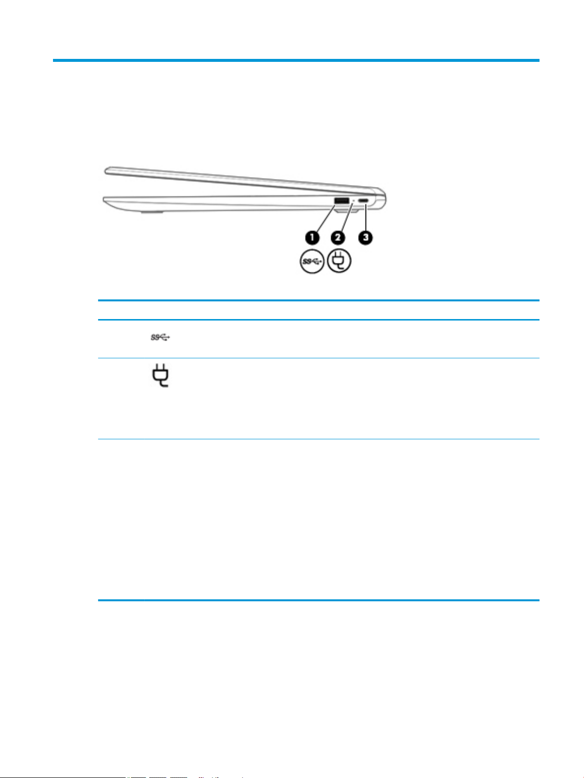
Right side
Table 2-1 Right-side components and their descriptions
Component Description
(1) USB SuperSpeed port Connects a USB device, such as a cell phone, camera,
activity tracker, or smartwatch, and provides high-speed
data transfer.
(2) AC adapter and battery light ● White: The computer is on, the AC adapter is
connected, and the battery is charged.
● Amber: The AC adapter is connected and the battery
is charging.
● O: The computer is using battery power or is turned
o.
(3) USB Type-C power connector and port Connects an AC adapter that has a USB Type-C connector,
supplying power to the computer and, if needed, charging
the computer battery.
– and –
Connects a USB device that has a Type-C connector, such as
a cell phone, camera, activity tracker, or smartwatch, and
provides data transfer.
– and –
Connects a display device that has a USB Type-C connector,
providing DisplayPort output.
NOTE: Cables and/or adapters (purchased separately)
may be required.
Right side 3
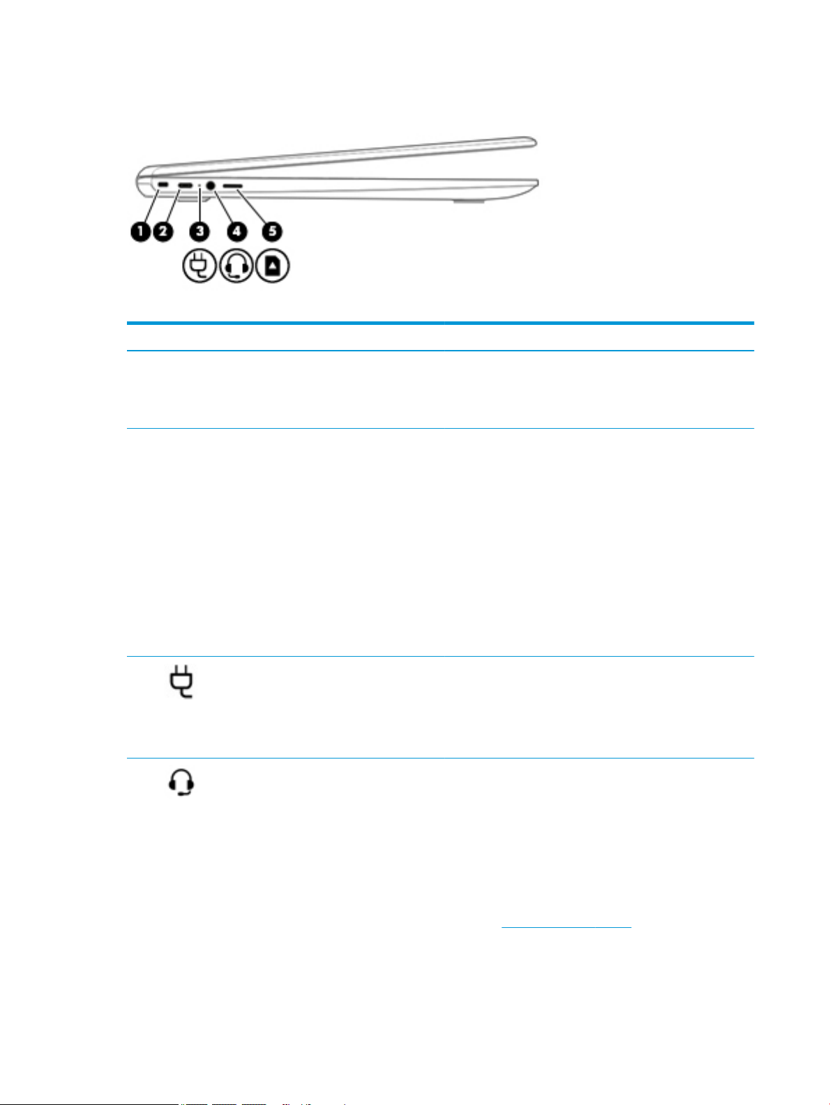
Left side
Table 2-2 Left-side components and their descriptions
Component Description
(1) Nano security cable slot Attaches an optional security cable to the computer.
(2) USB Type-C power connector and port Connects an AC adapter that has a USB Type-C connector,
NOTE: The security cable is designed to act as a deterrent, but
it may not prevent the computer from being mishandled or
stolen.
supplying power to the computer and, if needed, charging the
computer battery.
– and –
Connects a USB device that has a Type-C connector, such as a cell
phone, camera, activity tracker, or smartwatch, and provides
data transfer.
– and –
Connects a display device that has a USB Type-C connector,
providing DisplayPort output.
NOTE: Cables and/or adapters (purchased separately) may be
required.
(3) AC adapter and battery light ● White: The computer is on and the AC adapter is connected
(4) Audio-out (headphone)/Audio-in (microphone)
combo jack
4 Chapter 2 Getting to know your computer
and the battery is charged.
● Amber: The AC adapter is connected and the battery is
charging.
● O: The computer is using battery power or is turned o.
Connects optional powered stereo speakers, headphones,
earbuds, a headset, or a television audio cable. Also connects an
optional headset microphone. This jack does not support
optional microphone-only devices.
WARNING! To reduce the risk of personal injury, adjust the
volume before putting on headphones, earbuds, or a headset.
For additional safety information, see the Regulatory, Safety,
and Environmental Notices.
To access this guide:
● Go to http://www.hp.com/support, and follow the
instructions to nd your product. Then select User Guides.

Table 2-2 Left-side components and their descriptions (continued)
Component Description
NOTE: When a device is connected to the jack, the computer
speakers are disabled.
(5) microSD™ memory card reader Reads optional memory cards that enable you to store, manage,
share, or access information.
To insert a card:
1. Hold the card label-side up, with connectors facing the
computer.
2. Insert the card into the memory card reader, and then press
in on the card until it is rmly seated.
To remove a card:
▲ Press in on the card, and then remove it from the memory
card reader.
Left side 5
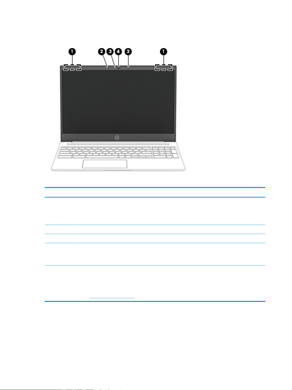
Display
Table 2-3 Display components and their descriptions
Component Description
(1) WLAN antennas* Send and receive wireless signals to communicate with wireless
local area networks (WLANs).
NOTE: The position of the WLAN antennas may dier,
depending on the product.
(2) Internal microphones (2) Record sound.
(3) Camera light On: The camera is in use.
(4) Camera Allows you to video chat, record video, and record still images.
NOTE: Camera functions vary depending on the camera
hardware and software installed on your product.
*The antennas are not visible from the outside of the computer, and antenna location varies. For optimal transmission, keep the areas
immediately around the antennas free from obstructions.
For wireless regulatory notices, see the section of the Regulatory, Safety, and Environmental Notices that applies to your country or
region.
To access this guide, go to http://www.hp.com/support, and follow the instructions to nd your product. Then select User Guides.
6 Chapter 2 Getting to know your computer

Touchpad
Table 2-4 Touchpad component and description
Component Description
Touchpad zone Reads your nger gestures to move the pointer or activate items on the screen.
Touchpad 7
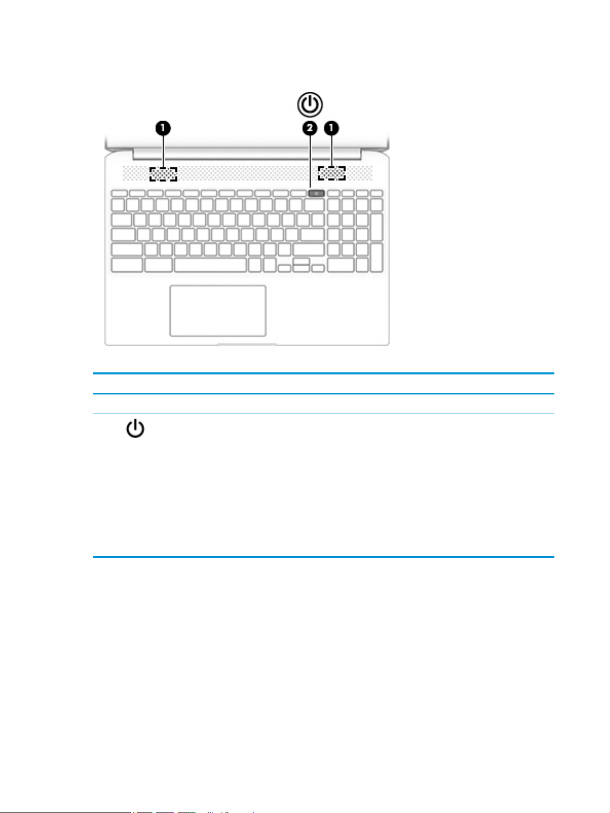
Button and speakers
Table 2-5 Button and speakers and their descriptions
Component Description
(1) Speakers (2) Produce sound.
(2) Power button ● When the computer is o, press the button to turn on the
computer.
● When the computer is in the Sleep state, press the button
briey to exit Sleep.
● When the computer is on and you want to lock the screen,
press the button until you see the sign-in screen appear.
Pressing the power button during screen-lock mode turns
o the computer.
● When the computer is on and you want to turn it o, press
and hold the button to lock the screen, and then continue
to press the button until the computer turns o.
8 Chapter 2 Getting to know your computer
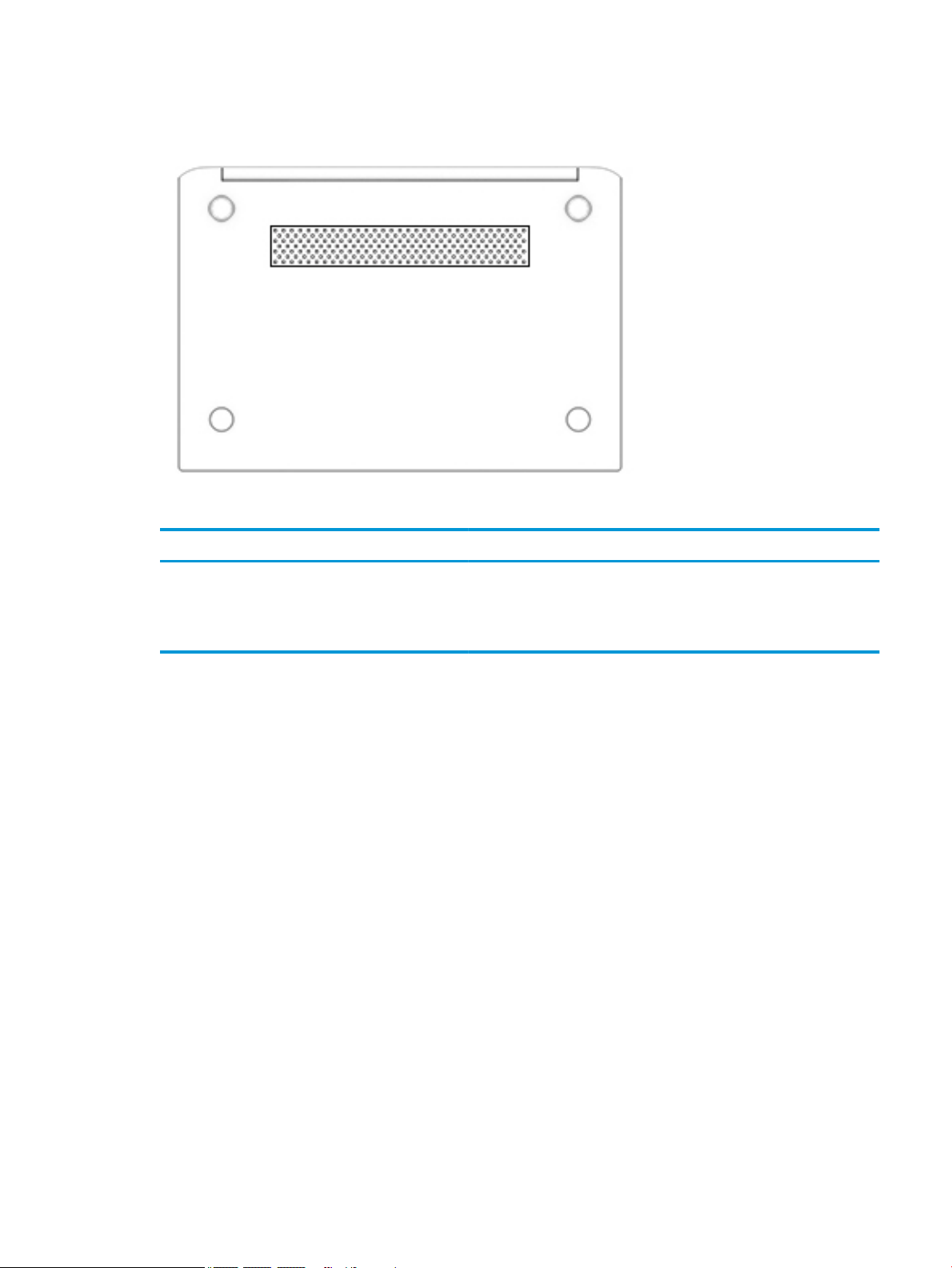
Bottom
Table 2-6 Bottom components and their descriptions
Component Description
Vent Enables airow to cool internal components.
NOTE: The computer fan starts up automatically to cool internal
components and prevent overheating. It is normal for the internal fan to
cycle on and o during routine operation.
Bottom 9
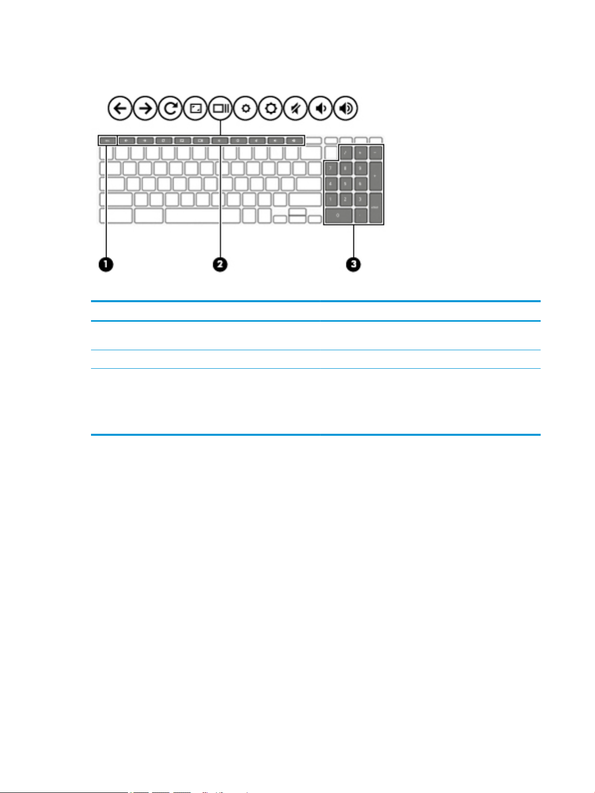
Special keys
Table 2-7 Special keys and their descriptions
Component Description
(1) esc key Activates certain computer functions when pressed in
(2) Action keys Execute frequently used system functions.
combination with other keys, such as Tab or Shift.
(3) Integrated numeric keypad A separate keypad to the right of the alphabet keyboard. The
keypad can be used like an external numeric keypad.
NOTE: If the keypad function is active when the computer is
turned o, that function is reinstated when the computer is
turned back on.
10 Chapter 2 Getting to know your computer

Labels
The labels axed to the computer provide information you may need when you troubleshoot system
problems or travel internationally with the computer. Labels may be in paper form or imprinted on the
product.
IMPORTANT: Check the following locations for the labels described in this section: the bottom of the
computer, inside the battery bay, under the service door, on the back of the display, or on the bottom of a
tablet kickstand.
● Service label—Provides important information to identify your computer. When contacting support, you
may be asked for the serial number, the product number, or the model number. Locate this information
before you contact support.
Table 2-8 Service label components
Component
(1) Product name
(2) Product ID
(3) Serial number
(4) Warranty period
● Regulatory label(s)—Provide(s) regulatory information about the computer.
● Wireless certication label(s)—Provide(s) information about optional wireless devices and the approval
markings for the countries or regions in which the devices have been approved for use.
Labels 11
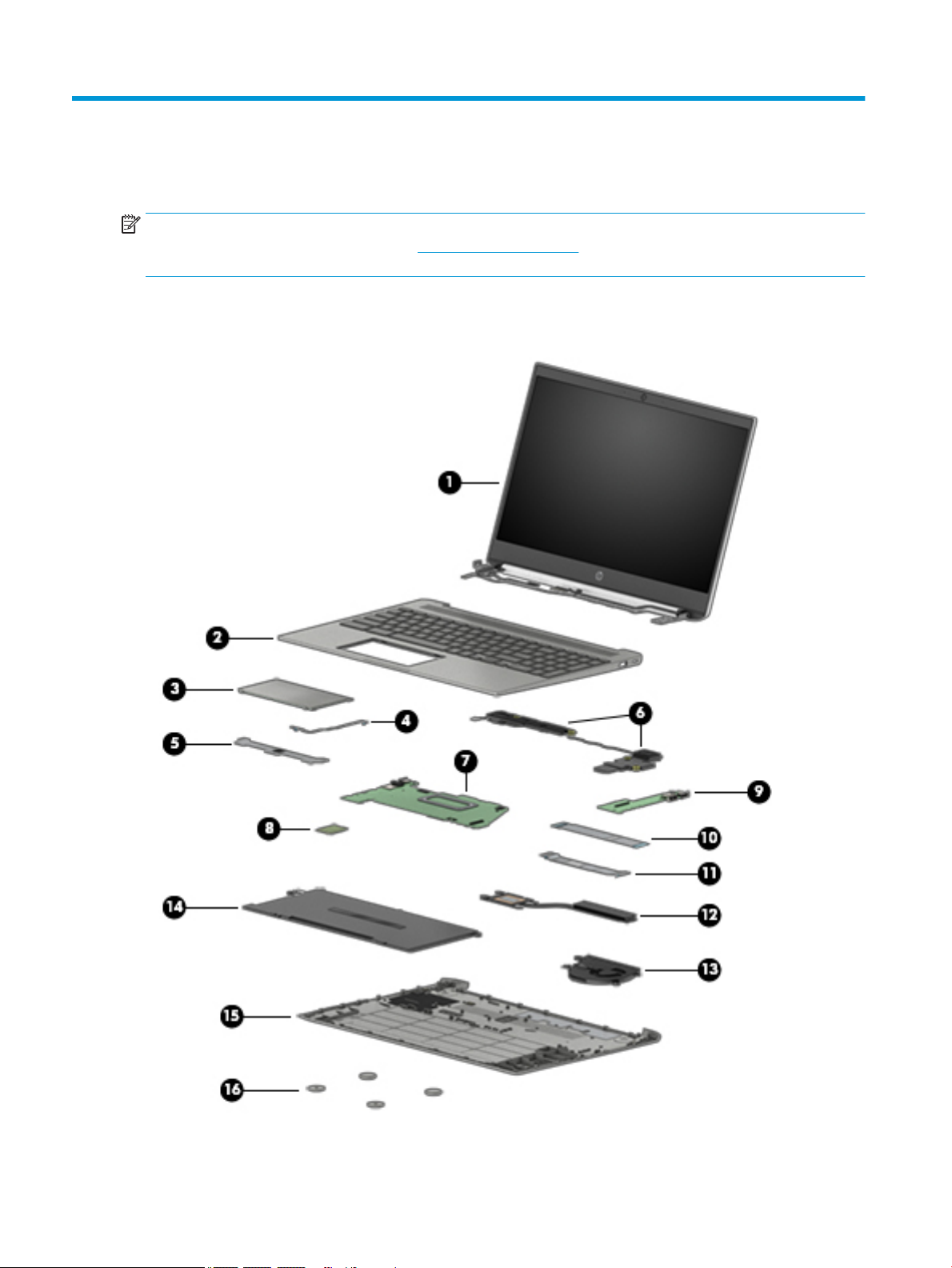
3 Illustrated parts catalog
NOTE: HP continually improves and changes product parts. For complete and current information on
supported parts for your computer, go to http://partsurfer.hp.com, select your country or region, and then
follow the on-screen instructions.
Computer components
12 Chapter 3 Illustrated parts catalog
 Loading...