

Page 1
Cascading Failover in a Continentalclusters
Introduction......................................................................................................................................... 2
Overview ........................................................................................................................................ 2
Purpose .......................................................................................................................................... 3
Terminology .................................................................................................................................... 3
Audience ........................................................................................................................................ 4
Configuration...................................................................................................................................... 4
Cluster and Storage Requirements...................................................................................................... 4
Volume Group Setup ........................................................................................................................ 4
Data Initialization............................................................................................................................. 5
Refreshing data on the Recovery Site.................................................................................................. 6
Package Setup .................................................................................................................................... 7
Primary Cluster Package Setup .......................................................................................................... 8
Recovery Cluster Package Setup ........................................................................................................ 8
Steps for Failure and Recovery Scenarios ............................................................................................... 8
Failure of Primary Site within Primary Cluster....................................................................................... 8
Failback from the Secondary Site to the Primary Site ............................................................................9
Failure of Secondary Site within the Primary Cluster ........................................................................... 10
Failover from Primary Cluster to Recovery Cluster...............................................................................11
Failback from the Recovery Cluster to the Secondary Site within the Primary Cluster............................... 11
Failback from the Recovery Site Directly to the Primary Site in the Primary Cluster .................................. 12
For more information.......................................................................................................................... 14
Page 2

Introduction
Overview
Cascading failover is the ability for an application to fail from a primary to a secondary location, and
then to fail to a recovery location. The primary location, the primary and secondary site, contains a
metropolitan cluster built with the HP Metrocluster solution, and the recovery location as a standard
Serviceguard cluster. Continentalclusters provides a “push-button” recovery between Serviceguard
clusters. Data replication also follows the cascading model. Data is synchronously replicated from the
primary disk array to the secondary disk array in the Metrocluster, and periodically data is manually
replicated via storage data replication technology to the third disk array in the Serviceguard recovery
cluster.
Continentalclusters with cascading failover uses three main data centers distributed between a
metropolitan cluster, which serves as a primary cluster, and a standard cluster, which serves as a
recovery cluster.
In the primary cluster, there are two disk arrays, either of which can have the source volumes for a
particular application. Throughout this document, the term primary disk array refers to the disk array
that holds the volumes that are being replicated to the remote disk array for a particular application,
and the data center where this disk array is located is called the primary site. The term secondary disk
array refers to the disk array that holds the volumes that the data is being replicated to using the
storage specific replication technology for a particular application, and the data center where the
secondary disk array for that application is located is known as the secondary site. Thus, primary and
secondary sites are roles that can be played by either disk array in the primary cluster. However,
once the data replication link has been defined for the secondary disk array to the recovery disk
array, primary and secondary sites will be fixed.
The recovery disk array holds a remote replicated copy of the data in the recovery cluster. The data
center that houses the recovery disk array is called the recovery site. The data is replicated from the
secondary disk array to the recovery disk array through manual operations or custom made scripts.
The basic design of the cascading failover solution is shown in Figure 1. The primary cluster, shown
on the left, is configured as a Metrocluster with three data centers physically located on three different
sites—two main sites (primary and secondary sites) and an arbitrator site (a third location) which is
not shown in the figure below. The primary and secondary sites can relative to the application given
that data replication is possible from both disk arrays in the primary cluster to the disk array in the
recovery cluster. A fourth data center (recovery site) is used for the recovery cluster, which is a
standard Serviceguard configuration. Also, the primary and recovery cluster are configured as a
Continentalclusters.
2
Page 3
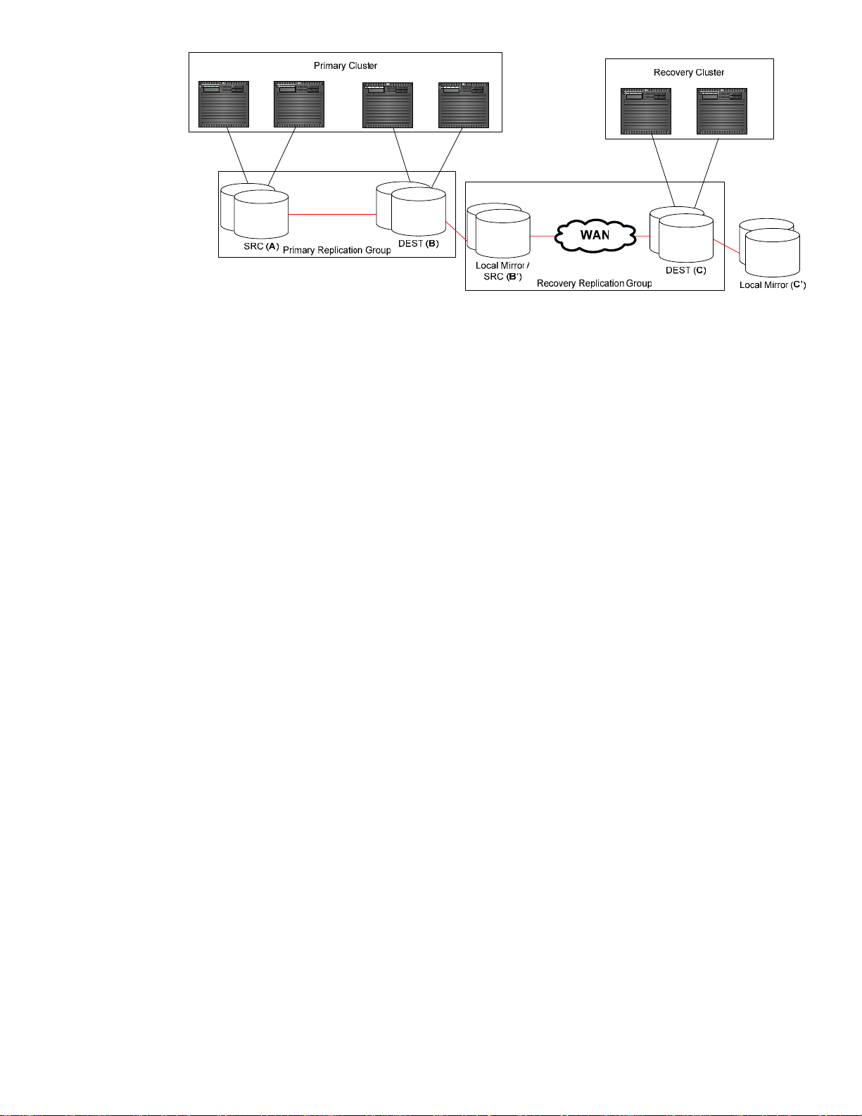
Figure 1 - Replication Setup
Also, the figure shows at a high level how the data replication is connected. In the primary cluster, the
primary replication group has two devices: a source device (connected to the primary site labeled as
device A) and a destination (connected to the secondary site and labeled as device B). Data is
replicated via storage data replication facilities (e.g. Continuous Access) continuously from source to
destination. On the secondary site, a local mirror is associated with the destination devices (labeled
as device B’). The mirror technology is storage specific (e.g. Business Copy). This local mirror also
acts as a source device for the recovery replication group and recovery during rolling disasters. In the
recovery cluster, the destination device (labeled as device C) of the recovery replication group are
connected to the nodes in the cluster. Data is periodically replicated to the destination devices via
storage data replication technology. Also, a local mirror of the destination device is required for
cases of rolling disasters (labeled as device C’).
Currently, HP StorageWorks XP Continuous Access (CA) and EMC Symmetrix SRDF technologies are
supported for the multi-site disaster tolerant solution.
Purpose
This document introduces the cascaded configuration in a Continentalclusters environment. This
includes configuration, maintenance, and recovery procedure for the cascaded configuration
environment.
Terminology
Throughout this document, the following terms refer to high level operations performed under a
cascaded configuration scenario. These defined terms are not general terms that are used in other
documents referring to data replication, clustering, and multi-site disaster tolerant solutions.
The device where I/O can be performed is referred to as the source. The data that is written to the
source device will be replicated to another device remotely. This remote device is referred to as the
destination (or destination device). For the XP CA data replication technology, the correct terminology
for source and destination are PVOL and SVOL respectively. For the EMC SRDF data replication
technology, source and destination are R1 and R2 respectively. Local mirror is the name for a local
copy of a device on the same disk array. Business Copy (BC) for HP XP and Business Continuance
Volumes (BCV) for EMC SRDF are the supported local mirroring capabilities used for the Metrocluster
and Continentalclusters products. A replication group is a pairing of source and destination devices
where the source replicates data to its assigned destination. In the cascaded configuration, there are
two replication groups. The replication group in the primary cluster is referred to as the primary
3
Page 4

replication group and the replication group from the secondary site to the recovery site is referred to
as the recovery replication group.
The following are three actions used to perform data replication specific operations.
• Establish: To “establish” a replication group or the replication link refers to enabling data to
be replicated from source to the destination or vice versa. This sometimes involves a block or
track level copy to the out of date copy and thus while copying is going on, the device being
replicated to is inconsistent. Unless stated, the data is copied from source to the destination.
• Split: To “split” a replication, the data replication link, or the local mirror refers to stopping
the data replication from source to destination or from a device to a local mirror.
• Restore: To “restore” refers to copying data from a local mirror to a device in the
replication group.
Audience
It is assumed that readers are already familiar with Serviceguard configuration tasks,
Continentalclusters installation and configuration procedures, HP StorageWorks XP, EMC Symmetrix,
BC, BCV, XP CA, SRDF, XP CA and Symmetrix multi-hop concepts, and configuration and usage of
the Raid Manager command line interface and Symmetrix Command Line Interface (SymCLI).
Configuration
Cluster and Storage Requirements
Most physical data replication technologies have the option to perform automatic link recovery. The
automatic link recovery provides the ability synchronize data from source to destination devices when
the data replication links have been recovered. For the cascading failover solution, this option to
automatically recover links should be “disabled”. This will keep the links from automatically trying to
establish a new connection upon failure of all links. This is required to allow the time to split the local
mirror on the secondary disk array (device B’) and the recovery replication group before reestablishing the data replication for the primary replication group (that is between the primary disk
array and the secondary disk array upon link recovery).
Other than what has been stated above, there are no additional cluster or storage requirements
besides what is required by the Continentalclusters product.
Volume Group Setup
Use the following procedure to set up volume groups for the devices used on the disk arrays.
Currently, LVM and VxVM volume management software suites are supported for this configuration.
Please refer to LVM and VxVM documentation for specific commands.
1. Before creating the volume groups, make sure that the data replication link is established
between the primary devices on the primary disk array and the destination devices on the
secondary disk array (i.e. devices A and B), and the local mirror device (device B’) in the
secondary disk array are established as mirrors of the local standard devices.
2. Create the volume group only on one cluster node that connects to the primary disk array.
3. For LVM and VxVM, metadata needs to be replicated to the destination devices (devices C
and C’) in the recovery disk. The following are steps to replicate data to the recovery site.
4
Page 5
a. Split the local mirror devices (device B’) in the secondary disk array from the primary
replication group.
b. Establish the data replication link between the local mirror devices in secondary disk
array (device B’) and the destination devices (device C) in the recovery disk array
(i.e. establish the recovery replication group).
c. Check the data synchronization process and wait until synchronization completes.
d. Once the synchronization completes, split the data replication link between the
secondary disk array and the recovery disk array (i.e. the recovery replication
group).
e. Establish the local mirror devices (device C’) in the recovery disk array as mirrors of
the standard devices.
f. Re-establish the local mirror devices (device B’) to the primary replication group as a
mirror of the standard device.
4. LVM requires to import volume group information. Please follow LVM specific commands to
configuration volume groups on all the nodes that are connected to the disk arrays.
Before Serviceguard and Continentalclusters can be configured, the created volume groups must work
properly on all nodes in connected to the disk arrays. Please refer to the specific volume group
management documentation for procedure for importing and activating the volume group on a given
node.
Data Initialization
If there is already a metropolitan cluster with the data replication already established with a local
mirror configured for rolling disasters and you are now adding Continentalclusters into the
configuration (that is adding a recovery site with a recovery disk array), only procedure 2 is required.
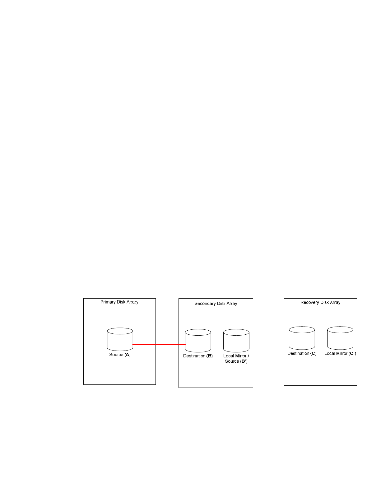
Procedure 1: Mirroring from the Primary to the Secondary Disk Array
This procedure is illustrated in Figure 2.
Figure 2 - Mirroring from the Primary to the Secondary Disk Array
Execute the following steps:
1. Establish mirroring of the secondary device (device B) to the local mirror device (device B’) in
the secondary disk array.
2. Establish replication of the primary replication group which is between the primary site and
the secondary site in the primary cluster.
5
Page 6

3. Start the application on the primary site in the primary cluster.
Procedure 2: Replicating from the Secondary to the Recovery Disk Array
This procedure is illustrated in Figure 3.
Figure 3 - Replicating from the Secondary to the Recovery Disk Array
Execute the following steps:
1. Freeze the application I/O to prevent the application from writing data to the primary
devices in the primary disk array (in case of adding the recovery cluster to the existing
Metrocluster). Note, that the method of freezing the I/O is application dependent
2. Split the local mirror devices (device B’) in the secondary disk array from the primary
replication group
3. Resume the application I/O to the primary devices in the primary disk array if needed. Also,
note that the method of resuming the I/O is application dependent.
4. Establish the data replication between secondary disk array (device B’) and the recovery disk
array (device C). The data is copied from local mirror devices on the secondary disk array to
the destination devices on the recovery disk array.
5. Check the data synchronization state of the replication. Wait until the data replication
completes.
6. Once the copy completes, split the data replication link between the secondary disk array
and the recovery disk array (that is the recovery replication group).
7. Incrementally establish the local mirror devices in (device C’) the recovery disk array as
mirrors of the standard devices if they are not already established. These devices were fully
established when the volume group were created.
8. Re-establish the local mirror devices (device B’) in the secondary disk array as mirrors of the
standard devices.
Refreshing data on the Recovery Site
Once the application starts writing data to the primary disk array devices, the data on the recovery
disk array is out of sync with the primary data; the data is not current but consistent. The data from
the primary cluster needs to periodically replicate to the recovery disk array, so its data is more up to
date. As long as the application continues writing new data to the primary disk array, the data on
the recovery disk array will always be behind. The level of data currency on the recovery disk array is
6
Page 7

dictated by the frequency at which it is refreshed (that is data replicated from primary site to recovery
site). The refresh process is shown in Figure 4.
Figure 4 - Data Refresh in Steady State
The following procedure describes the steps necessary to periodically copy the data from the
secondary disk array to the recovery disk array while the application is running on the primary site.
1. Freeze the application I/O to prevent the application from writing data to the primary
devices in the primary disk array. Note, the method of freezing the I/O is application
dependent.
2. Make sure that data has replicated to the remote site before executing the next step.
3. Split the local mirror devices (device B’) in the secondary disk array from the primary
replication group.
4. Resume the application I/O to the primary devices in the primary disk array if needed. Note,
the method of resuming the I/O is application dependent.
5. Split the local mirror devices (device C’) in the recovery disk array from the secondary
replication group. This is required to preserve an old copy of the data just in case a failure
occurs during data synchronization between the secondary disk array and the recovery disk
array that may cause data corruption on the destination devices in the recovery disk array.
6. Incrementally establish the secondary replication group (i.e. group between the secondary
disk array and the recovery disk array). The data is copied from secondary disk array local
mirror devices (device B’) to the recovery disk array secondary devices (device C).
7. Wait until the copying has completed before continuing to the next step.
8. Once the copy completes, split the data replication link between the secondary disk array
and the recovery disk array.
9. Re-establish the local mirror devices (device C’) in the recovery disk array as mirrors of the
secondary devices.
10. Re-establish the local mirror devices (device B’) in the secondary disk array as mirrors of the
secondary devices of the primary replication group.
Package Setup
Except for the following package setup instructions, packages for both primary and recovery follow
the same steps as setting up a Continentalclusters package. See the Designing Disaster Tolerant High
Availability Clusters manual for more information on setting up packages.
7
Page 8

Primary Cluster Package Setup
Cascading failover uses a Continentalclusters in which the primary cluster is configured as a
metropolitan cluster. The following are two differences from the normal Continentalclusters
configuration in customizing the environment file.
1. Instead of the CLUSTER_TYPE variable being set to “continental”, it should be set to “metro.”
2. The DEVICE_GROUP variable should be set to the disk array device group name defined in
the primary and secondary disk array according to what disk array is directly connected to
the node.
Before executing the cmapplyconf on the primary cluster, make sure to split the data replication links,
between the primary disk array and the secondary disk array, for the disks associated with the
application package.
Recovery Cluster Package Setup
There is a slight difference from the normal Continentalclusters configuration in customizing the
recovery package environment file. The DEVICE_GROUP variable should be set to the disk array
device group name that was defined in the recovery disk array.
Just as with the primary cluster setup, before running cmapplyconf command for the recovery cluster,
make sure to split the data replication links, between the secondary disk array and the recovery disk
array, for the disks associated with the application package.
Steps for Failure and Recovery Scenarios
This section describes the procedures for the following various failover and failback scenarios:
• Failure of Primary Site within Primary Cluster
• Failback from the Secondary Site to the Primary Site
• Failure of Secondary Site within the Primary Cluster
• Failover from Primary Cluster to Recovery Cluster
• Failback from the Recovery Cluster to the Secondary Site within the Primary Cluster
• Failback from the Recovery Site Directly to the Primary Site in the Primary Cluster
Failure of Primary Site within Primary Cluster
When a failure occurs at the primary site, the hosts are down or the whole site is down, the
application package automatically fails over to the secondary site within the primary cluster. Until
the problems at the primary site are fixed, and data replication is reestablished, there is no remote
data protection for the package at the secondary site. Depending on the type of failure and how
quickly the primary site is back online, data refresh to the recovery site is still needed. This scenario is
illustrated in Figure 5.
8
Page 9

Figure 5 - Failure of Primary Site in Primary Cluster
After failover, the application is running on secondary site and writing I/O to destination devices.
The data is not remotely protected. The procedure to refresh the data from the secondary disk array
to the recovery disk array is the same as the one that is done normally for refreshing the data on the
recovery site. Follow the step in the previous section, “Refreshing data on the Recovery Site.”
Failback from the Secondary Site to the Primary Site
Once the problems at the primary site have been fixed, the application can fail back to the primary
site, however, usually the current state of the replication group will not be in an automated state for
Metrocluster. Therefore, a user needs to consult the specific data replication technology to restore the
device back to a Metrocluster supported state. The following steps are required to move the package
back to the primary site.
1. Set the primary replication group between primary disk array and secondary disk array into
a “synchronized” state where the consistent data has been copied back to the source device
and replication is enabled to copy data from source to destination.
2. Now, halt the application package:
# cmhaltpkg <package_name>
3. Split the local mirror (device B’) in the secondary disk array from the primary replication
group to save a consistent copy of the data.
4. Start the application package on the primary site. Use the following command for all hosts in
the primary cluster that may run this package:
# cmmodpkg -e -n <host_name> <package_name>
Then run the package with the following command:
# cmmodpkg -e <package_name>
The package will now start up on its primary host. Metrocluster will initialize a failback. The
failback will synchronize the primary devices from the secondary devices. Until the
synchronization is complete, the package application may run at a lower performance level.
5. Check the replication pair state between the primary disk array and the secondary disk
array.
9
Page 10
6. Re-establish the local mirror devices (device B’) in the secondary disk array.
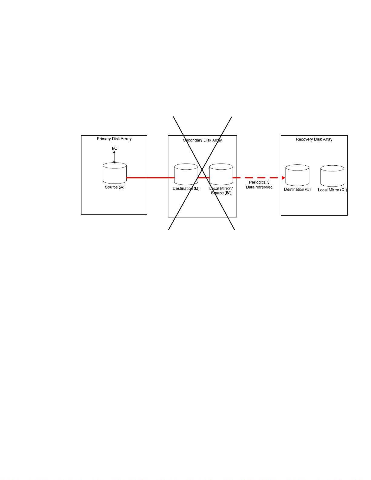
Failure of Secondary Site within the Primary Cluster
When the secondary site fails, or all data replication links between the primary disk array and the
secondary disk array fail, unless data storage specific technology that will be suspend I/O operations
under such cases is used (for example, replication mode DATA for HP XP CA or Domino Mode for
EMC SRDF), the application running on the primary site is not aware of this failure and continues to
run on the primary site. This scenario is illustrated in Figure 6.
Figure 6 - Failure of Secondary Site in Primary Cluster
Without the secondary site, the current configuration does not provide any means to replicate the new
data from the primary disk array directly to the recovery disk array. If the secondary site is down for
a long time, the data in the recovery disk array is very out-of-date. If the primary site fails during this
time, and the recovery site takes over, the customer will have to operate on an old copy of the data.
Therefore, it's important to fix and have the secondary site up and running as soon as possible.
When the secondary site is fixed, the replication pair between the primary disk array and the
secondary disk array will not be synchronized. If the local mirror in the secondary disk array
contains a good copy of the data, to protect this data from corruption in case of rolling disaster, these
devices must be split from the primary replication group before re-establishing the primary replication
pairs between the primary disk array and the secondary disk array. Use the following steps:
1. Split the local devices (device B’) in the secondary disk array from the primary replication
group.
2. Incrementally establish the primary replication pairs between the primary disk array and the
secondary disk array.
3. Check the state of the primary replication pair. Make sure that the data resynchronization has
completed from the primary site to the secondary site.
4. Once the copy completes, re-establish the local mirror devices in the secondary disk array
10
Page 11

Failover from Primary Cluster to Recovery Cluster
After reception of the Continentalclusters alert and alarm, the administrators at the recovery site follow
the prescribed processes and recovery procedures to start the protected applications on the recovery
cluster. Note that data corruption may occur in situation where a disaster occurs at the primary cluster
while the data refresh from secondary disk array to the recovery disk array is in progress. Under
these circumstances, the data in the recovery replication group devices in the recovery disk array is
not usable. The data can be recovered by restoring an old copy of the data from the local mirror
devices (device C’) in the recovery disk array; as shown in Figure 7.
Figure 7 – Failover from Primary Site to Recovery Cluster
Execute the following commands to restore the data:
1. If the data was being refreshed from the primary site to the recovery site, restore the data
from the local mirror to the recovery replication group devices in the recovery disk array.
2. Check the data restore progress assuming step 1 applies.
3. Once the restore completed, split the local mirror device (device C’) from the recovery
replication group. The data in the recovery disk array may not be current but should be
consistent. There is no additional procedure needed. Metrocluster is programmed to handle
this case.
4. After the application is up and running, re-establish the local mirror devices as mirrors of the
standard devices for an additional copy of the data.
Failback from the Recovery Cluster to the Secondary Site within the
Primary Cluster
This procedure is used when the application fails back and runs on the secondary site while the
primary site is still down.
1. Halt the Continentalclusters monitor package.
2. Halt the Continentalclusters recovery packages at the recovery site.
3. Split the local mirror device (device C’) from the recovery replication group in the recovery
disk array.
11
Page 12

4. Re-establish the recovery replication pairs between the recovery disk array and the secondary
disk array. Move the data from the recovery disk array (device C) to the secondary disk
array (device B’).
5. Check the data resynchronization progress of the recovery replication group.
6. Once the data resynchronization completes, split the data replication link between secondary
disk array and recovery disk array.
7. Re-establish the local mirror devices (device B’) in the secondary disk array. Restore the data
from the local mirror devices to the devices in the primary replication group (device B).
8. Check the data restore progress between the local mirror and the devices in the primary
replication group.
9. For LVM, Since the recovery cluster has a different cluster ID, the data restored from the
recovery disk array to the secondary disk array also copies the recovery cluster’s ID to the
secondary disk array. Do the following to change the cluster’s ID on each cluster aware
volume group in the secondary disk array before starting the application package:
# vgchange -c n /dev/<vg_name>
# vgchange -c y /dev/<vg_name>
For VxVM, the disk group needs to be imported with a force flag in order to clear the hostid
of a node from the recovery site. Perform the following command on each disk group on a
node in the primary cluster:
# vxdg –tfC <disk_group_name>
10. Start the application package at the secondary site. Issue the following command for all hosts
in secondary site that may run this package:
# cmmodpkg -e -n <host_name> <package_name>
11. Then issue the following command from any node on the primary cluster:
# cmmodpkg -e <package_name>
12. Start the Continentalclusters monitor package.
Failback from the Recovery Site Directly to the Primary Site in the Primary
Cluster
The current configuration does not support the application failback to the primary site in the primary
cluster unless the secondary site in the primary cluster is up and running. The secondary site has to
be repaired first. The application can temporarily fail back to the secondary site while the primary
site is still down. Before the application can failback to either the secondary site or the primary site,
the current data needs to be restored from the recovery disk array to the secondary disk array and the
primary disk array.
This procedure is used when both the secondary site and the primary site are fixed and up and
running. The package application fails back directly from the Recover cluster to the primary site in the
primary cluster.
1. Halt the Continentalclusters monitor package at the recovery site.
2. Halt the Continentalclusters recovery packages at the recovery site.
12
Page 13

3. Split the local mirror (device B’) from the primary replication group in the secondary disk
array.
4. Re-establish the recovery replication group between the recovery disk array and the
secondary disk array. Note, the data is copied from the recovery disk array (device C) to the
secondary disk array (device B’).
5. Check the data copy from the devices in the recovery disk array to the local devices of the
recovery replication group in the secondary disk array.
6. Once the data copy completes, split the replication link between secondary disk array and
recovery disk array.
7. Re-establish the local mirror devices (device B’) in the secondary disk array as mirrors to the
primary replication group devices (device B). Restore the data from the local mirror devices
to the devices in the primary replication group.
8. Check the data restore from the local mirror to the devices in the primary replication group.
9. Once the data restore completes, split the local mirror devices from the primary replication
group.
10. Set the primary replication group such that the devices (device B) on the secondary disk are
read write-able.
11. For LVM, since the recovery cluster has a different cluster ID, the data restored from the
recovery disk array to the secondary disk array also copies the recovery cluster’s ID to the
secondary disk array. Do the following to change the cluster’s ID on each cluster aware
volume group in the secondary disk array before starting the application package:
# vgchange -c n /dev/<vg_name>
# vgchange -c y /dev/<vg_name>
For VxVM, the disk group needs to be imported with a force flag in order to clear the hostid
of a node from the recovery site. Perform the following command on each disk group on a
node in the primary cluster:
# vxdg –tfC <disk_group_name>
12. Start the package application at the primary site. Issue the following command for all hosts in
the primary cluster that may run this package:
# cmmodpkg -e -n <host_name> <package_name>
13. Start the package with the following command:
# cmmodpkg -e <package_name>
14. Start the Continentalclusters monitor package on the recovery cluster.
15. Check the primary replication group between the primary disk array and the secondary disk
array and make sure data replication is established.
16. Re-establish the local mirror devices (device B’) in the secondary disk array to the primary
replication group.
13
Page 14

For more information
For more information about Serviceguard and DTS products, refer to the following manuals:
• Designing Disaster Tolerant High Availability Clusters (B7660-90017)
• Managing Serviceguard Twelfth Edition (B3936-90095).
(For the most recent version go to: http://docs.hp.com/hpux/ha/index.html)
For documentation on XP disk array with Continuous Access XP, refer to the following:
• HP StorageWorks Disk Array XP Business Copy User’s Guide, Sixth Edition (B7906-96005)
• HP StorageWorks Disk Array XP Continuous Access User’s Guide, Sixth Edition (B7905-96006)
• HP StorageWorks Disk Array XP Raid Manager User’s Guide, Fourth Edition (T1610-96001)
• HP StorageWorks Disk Array XP Remote Control User’s Guide (B9357-96011)
Before attempting to use VxVM storage, refer to the following documents for your version of VERITAS
software:
• VERITAS Volume Manager Administrator’s Guide. This contains a glossary of VERITAS
terminology.
• VERITAS Volume Manager Storage Administrator Administrator’s Guide
• VERITAS Volume Manager Reference Guide
• VERITAS Volume Manager Migration Guide • VERITAS Volume Manager for HP-UX Release
Notes
For documentation on EMC Symmetrix disk array and the Symmetrix command line interface
(SymCLI), refer to the link:
EMC Symmetrix and SRDF data replication
© 2003 Hewlett-Packard Development Company, L.P. The information
contained herein is subject to change without notice. The only warranties for
HP products and services are set forth in the express warranty statements
accompanying such products and services. Nothing herein should be construed
as constituting an additional warranty. HP shall not be liable for technical or
editorial errors or omissions contained herein.
Itanium is a trademark or registered trademark of Intel Corporation in the U.S.
and other countries and is used under license.
XXXX-XXXXEN, 07/2003
 Loading...