

Page 1

HP Cache Server Appliance
Administrator Guide
HP Part Number 5971-3045
Printed in June 2001
Page 2

Notice
The information contained in thisdocument is subject to change without notice.
Hewlett-Packard makes no warrantyof any kind with regardtothis material, including, but notlimited
to, the implied warranties of merchantability and fitness for a particular purpose. Hewlett-Packard shall
not be liable for errors contained herein or for incidental or consequential damages in connection with the
furnishing, performance, or use of this material.
Hewlett-Packard assumes no responsibility for the use or reliability of its software on equipment that is not
furnished by Hewlett-Packard.
This document contains proprietaryinformation that is protected by copyright. All rights are reserved. No part
of this document may be photocopied, reproduced, or translated to another language without the prior written
consentof Hewlett-Packard Company.
UltraServer and SPARCstorage are trademarks of Sun Microsystems, Inc.; Myrinet is a trade name of Myricom, Inc.; UNIX is a registered trademark of AT&T. All other trademarksare the property of their respective
owners.
Hewlett-Packard Company
Network Server Division
Technical Communications/MS 45SLE
10955 Tantau Avenue
Cupertino, CA 95014 USA
© Copyright 2001, He wlett-Packard Company.
Audience Assumptions
This guide is for the person who installs, administers, and troubleshoots network infrastructure products.
Hewlett-Packard Company assumes you are qualified in the servicing of computer equipment and trained in
recognizing hazards in products with hazardous energy levels.
ii
Page 3

Contents
Preface ......................................................................... xii
Who should read this manual . . . . . ................................ xii
Conventionsusedinthismanual................................... xii
1 Overview....................................................................... 1
WhatisTrafficServer?.........................................1
Traffic Server deployment options . . .................................1
TrafficServerasawebproxycache.................................2
TrafficServerasareverseproxy...................................2
TrafficServerinacachehierarchy..................................2
TrafficServerinacluster.......................................2
Traffic Server components . . . . . . .................................3
TheTrafficServercache.......................................3
The Adaptive Redirection Module (ARM) . .............................3
The Host Database. . ........................................3
TheDNSResolver..........................................4
TrafficServerprocesses.......................................4
Administrationtools..........................................5
Trafficanalysisoptions.........................................5
TrafficServersecurityoptions .....................................5
2 GettingStarted.................................................................. 7
Overview of Access Methods . . . . . .................................7
Verifying that Traffic Serv er is up and running .............................8
Accessing Traffic Manager . . . . . . .................................8
UsingtheMonitorandConfiguretabs................................9
Usingonlinehelp...........................................9
StartingTrafficLine..........................................10
RestartingTrafficServer....................................... 10
3 WebProxyCaching ............................................................. 11
Understanding web proxy caching . . ................................11
Adayinthelifeofacacherequest.................................11
Ensuring cached object freshness . . ................................12
RevalidatingHTTPobjects.....................................12
HTTP object freshness tests . . . . ................................13
DecidingwhethertoserveHTTPobjects..............................13
ConfiguringHTTPfreshnessoptions................................14
CachingHTTPalternates...................................... 14
Scheduling updates to local cache content. ............................16
Newsarticlecaching......................................... 16
TrafficServerasanewsserver..................................17
TrafficServerasacachingproxynewsserver...........................17
Supporting several parent news servers . . ............................17
iii
Page 4

Contents
Blocking particular groups . . . . . ................................18
Clustering..............................................18
Transparency............................................19
Posting...............................................19
Maintaining the cache: updates and feeds . ............................19
Configuringaccesscontrol.....................................20
Using enhanced NNTP authentication . . . ............................20
Obeying NNTP control messages . ................................ 21
Clientbandwidththrottling.....................................21
4 TransparentProxyCaching....................................................... 22
Serving requests transparently . . . . ................................22
ARMredirection............................................22
Interceptionstrategies.........................................23
Using a layer 4 switch with cache switching functionality to filter transparency requests . . . . . 23
Using a WCCP-enabled router for transparency . . ........................ 24
Usingpolicy-basedroutingtofiltertransparencyrequests.....................27
Interceptionbypass..........................................28
Dynamicbypassrules.......................................29
Staticbypassrules......................................... 32
Viewingthecurrentsetofbypassrules ..............................32
ConfiguringARMsecurity .....................................32
5 ReverseProxyandHTTPRedirects................................................ 33
Understanding reverse proxy caching ................................33
Reverseproxysolutions......................................33
Howdoesreverseproxycachingwork?..............................34
HTTPReverseProxy......................................... 35
Handling origin server redirect responses . ............................35
Using mapping rules . .......................................36
SettingHTTPreverseproxyoptions................................38
FTPReverseProxy.......................................... 39
ConfiguringFTPReverseProxy..................................40
SettingFTPMappingRules....................................40
Enabling FTP Reverse Proxy. . . . ................................40
ModifyingFTPOptions.......................................41
Redirecting HTTP Requests . . . . . ................................43
6 TrafficServerClusters........................................................... 45
Understanding Traffic Server clusters. ................................45
Management-only clustering . . . . ................................45
Fullclustering............................................45
Changingclusteringmode.....................................46
Adding and deleting nodes in a clus ter ................................ 46
Adding nodes to a c luster . . . . . ................................46
Deleting nodes from a cluster . . . ................................47
VirtualIPfailover...........................................47
Setting virtual IP address options . ................................48
iv
Page 5

Contents
7 HierarchicalCaching ............................................................ 51
Understanding cache hierarchies . . . ................................51
HTTPcachehierarchies .......................................51
Parentfailover...........................................52
ConfiguringTrafficServertouseanHTTPparentcache.....................52
ICPcachehierarchies.........................................54
ConfiguringTrafficServertouseanICPcachehierarchy.....................54
8 Configuring the cache . . . ........................................................ 59
TheTrafficServerCache....................................... 59
RAMcache.............................................59
Partitioningthecache......................................... 59
Creatingcachepartitionsforspecificprotocols ..........................60
Partitioningthecacheaccordingtooriginserverordomain....................61
Clearingthecache..........................................62
9 MonitoringTraffic............................................................... 63
TrafficServermonitoringtools ....................................63
Viewing statistics from Traffic Manager ................................63
Starting Traffic Manager Monitor mode . . ............................63
UsingMonitormode........................................64
WorkingwithTrafficManagerAlarms.................................67
Resolvingalarms..........................................67
ConfiguringTrafficServertoE-mailalarms............................ 68
ViewingStatisticsfromTrafficLine..................................68
Viewing groups of statistics. . . . . ................................68
Retrievingindividualstatistics...................................69
UsingMRTG .............................................70
AccessingMRTG..........................................70
NavigatingMRTG .........................................70
UsingSNMP .............................................71
Enabling SNMP...........................................71
ConfiguringSNMPtrapdestinations................................72
10ConfiguringTrafficServer........................................................ 73
Configuring Traffic Server us ing Traffic Manager. . . ........................73
Starting Traffic Manager Configure mode . ............................73
UsingConfiguremode.......................................74
ConfiguringTrafficServerusingTrafficLine.............................76
StartingConfiguremode......................................76
NavigatingConfiguremode ....................................77
SettingconfigurationoptionsinConfiguremode..........................77
Settingconfigurationoptionsinbatchmode............................78
ConfiguringTrafficServerusingconfigurationfiles..........................78
11SecurityOptions................................................................ 80
TrafficServersecurityoptions ....................................80
ControllingclientaccesstotheTrafficServerproxycache...................... 81
ControllinghostaccesstotheTrafficServermachine(ARMsecurity)................81
v
Page 6

Contents
Controlling access to Traffic Manager ................................ 83
SettingtheadministratorIDandpassword.............................83
Creating a list of administrator accounts . . ............................85
Controlling host access to Traffic Manager. ............................86
UsingSSLforsecureadministration................................87
ConfiguringSOCKSfirewallintegration................................89
SettingSOCKSconfigurationoptions...............................89
ConfiguringDNSserverselection(splitDNS).............................91
Configuring LDAP-based proxy authentication ............................92
Configuring LDAP Authentication Bypass . ............................92
UsingSSLTermination........................................93
Client and Traffic Server connec t ions . . . ............................94
TrafficServerandoriginserverconnections............................96
12WorkingwithLogFiles........................................................... 98
Understanding Traffic Server log f iles. ................................98
Understanding event log files . . . . . ................................98
Managing event log files .......................................99
Choosingtheloggingdirectory...................................99
Controlling logging space. . . . . . ................................99
Setting log file management options ............................... 100
Choosingeventlogfileformats................................... 101
Using standard formats...................................... 101
Usingcustomformats...................................... 103
ChoosingbinaryorASCII .................................... 108
UsinglogcattoconvertbinarylogstoASCII........................... 108
Rollingeventlogfiles........................................ 109
Rolledlogfilenameformat.................................... 109
Rollingintervals.......................................... 110
Settinglogfilerollingoptions................................... 110
Splittingeventlogfiles ....................................... 112
NNTPlogsplitting ........................................ 112
ICPlogsplitting.......................................... 112
HTTPhostlogsplitting...................................... 112
Settinglogsplittingoptions.................................... 113
Editing the log_hosts.config file . . ............................... 114
Collatingeventlogfiles....................................... 115
Settinglogcollationoptions ................................... 116
Usingastand-alonecollator................................... 118
Recoveringlogfiles........................................ 119
Viewing logging statistics ...................................... 119
A TrafficManagerStatistics ....................................................... 120
The Dashboard page . . ...................................... 120
The Node page . .......................................... 121
The Graphs page .......................................... 121
The Protocols page . . . ...................................... 122
TheCachepage .......................................... 125
vi
Page 7

Contents
TheOtherpage........................................... 126
The MRTG page .......................................... 127
B TrafficManagerConfigurationOptions ............................................ 128
The Server Basics page. ...................................... 128
The Protocols page . . . ...................................... 131
TheCachepage .......................................... 135
The Security page.......................................... 137
The Routing page .......................................... 138
The Host Database page ...................................... 139
The Logging page.......................................... 140
The Snapshots page . . ...................................... 143
The Plugins page .......................................... 143
The Content Management page . . . ............................... 143
C TrafficLineCommands......................................................... 145
TrafficLinebatchmodecommands................................. 145
TrafficLineinteractivemodecommands.............................. 146
TrafficLinevariables........................................ 147
Statistics............................................. 147
ConfigurationOptions ...................................... 151
D ConfigurationFiles............................................................. 159
arm_security.config......................................... 160
Format.............................................. 160
Example............................................. 160
bypass.config............................................ 161
Format.............................................. 162
Example............................................. 162
cache.config............................................. 162
Format.............................................. 163
Example............................................. 164
filter.config.............................................. 164
Format.............................................. 164
Example............................................. 165
ftp_remap.config .......................................... 166
Format.............................................. 166
Example............................................. 166
hosting.config............................................ 166
Format.............................................. 167
Example............................................. 167
icp.config.............................................. 167
Format.............................................. 167
Example............................................. 168
ip_allow.config ........................................... 168
Format.............................................. 168
Example............................................. 169
ldapsrvr.config............................................ 169
Format.............................................. 169
vii
Page 8

Contents
Example............................................. 169
logs.config.............................................. 169
Format.............................................. 170
Example............................................. 170
WELF (WebTrends Enhanced Log Format) ........................... 171
log_hosts.config. .......................................... 171
Format.............................................. 171
Example............................................. 171
logs_xml.config........................................... 171
Format.............................................. 172
Example............................................. 175
WELF (WebTrends Enhanced Log Format) ........................... 175
mgmt_allow.config ......................................... 176
Format.............................................. 176
Example............................................. 176
nntp_access.config......................................... 176
Format.............................................. 176
nntp_servers.config......................................... 177
Format.............................................. 177
Example............................................. 179
parent.config ............................................ 179
Format.............................................. 180
Example............................................. 181
partition.config............................................ 181
Format.............................................. 182
Example............................................. 182
records.config............................................ 182
Format.............................................. 182
Example............................................. 183
Configurationvariables...................................... 183
remap.config ............................................ 212
Format.............................................. 212
Example............................................. 213
snmpd.cnf ............................................. 214
Format.............................................. 214
Configuringtrapdestinations................................... 215
Accesscontrol.......................................... 215
socks.config. . . .......................................... 216
Format.............................................. 216
Example............................................. 216
splitdns.config............................................ 217
Format.............................................. 217
Example............................................. 217
storage.config . . .......................................... 218
Format.............................................. 218
Example............................................. 218
update.config............................................ 218
Supported tag/attribute pairs . . . . ............................... 219
viii
Page 9

Contents
Format.............................................. 219
Example............................................. 220
Specifying URL Regular Expressions (url_regex). . . ....................... 220
Example............................................. 221
E EventLoggingFormats......................................................... 222
HP custom logging fields ...................................... 222
Loggingformatcrossreference................................... 224
Squidloggingformats...................................... 224
NetscapeCommonloggingformats............................... 225
Netscape Extended logging formats ............................... 225
Netscape Extended-2 logging formats . . . ........................... 225
F TrafficServerErrorMessages.................................................... 227
Traffic Server error m es s ages . . . . ............................... 227
TrafficServerNotes....................................... 227
TrafficServerProcessfatal.................................... 228
TrafficServerWarnings..................................... 228
Traffic Server alarm m ess ages . . . . ............................... 229
HTML messages sent to clients. . . . ............................... 230
Standard HTTP response messages . ............................... 232
Glossary ........................................................................ 233
Index............................................................................236
ix
Page 10

List of Procedures
To verify that T raffic Server is up and running: 8
To access Traffic Manager: 8
To start a Traffic Line session: 10
To enable WCCP 1.0 af t er Traffic Server installation: 25
To enable WCCP 2.0 after installation: 26
To set dynamic bypass rules: 29
To view dynamic bypass statistics: 31
To view all current dynamic and static bypas s rules: 32
To create a mapping rule from Traffic Manager: 36
To create a mapping rule manually: 37
To set reverse proxy options from Traffic Manager: 38
To set reverse proxy options manually: 38
To set FTP mapping rules: 4 0
To enable FTP reverse proxy: 40
To modify FTP options: 41
To set redirect rules: 44
To change clustering mode: 46
To add a cache appliance to a cluster: 46
To delete a node from a c lust er: 47
To enable/disable virtual IP addressing from Traffic Manager: 48
To enable/disable virtual IP addressing manually: 49
To add or edit virtua l IP addresses from Traffic Manager: 49
To add or edit v irtual IP addresses manually: 50
To enable the HTTP parent caching option from Traffic Manager: 52
To enable HTTP parent caching manually: 53
To identify an HTTP parent cache from Traffic Manager: 53
To set ICP options from Traffic Manager: 55
To set ICP options manually: 55
To identify an ICP peer from Traffic Manager: 56
To identify an ICP peer manually: 57
To partition the cache according to protocol: 60
To partition the cache according to hostname and domain: 61
To clear the cache: 62
To start Traffic M anager Monitor mode: 63
To start Monitor mode: 68
Toretrieveasinglestatistic:69
To access MRTG: 70
To enable the SNMP agent from Traf fic Manager: 71
To enable the SNMP agent manually: 71
To start Traffic M anager Configure mode: 73
To start Configure mode: 76
x
Page 11

List of Procedures
To set configuration options in Configure m ode: 77
To set configuration options in ba tch mode: 78
To specify the clients allowed to use Traffic Server as a proxy cache: 81
To edit the arm_security.config file and enable the ARM security option: 82
To change the administrator ID and password: 83
To clear and re-enter the administrator password: 84
To create a list of administrator accounts: 85
To control which hosts can access Traffic Manager: 86
To enable SSL from Traffic Manager: 87
To enable SSL manually: 88
To set SOCKS options from Traffic Manager: 89
To set SOCKS options manually: 91
To configure DNS server selection: 91
To configure LDAP-based proxy authentication: 92
To enable clients to access specific sites without LDA P auth enti c ation: 92
To set SSL termination conf iguration variables for c lient/Traffic Server connections: 95
To set SSL termination configuration variables for Traffic Server/origin server connections: 97
To set log management options from Traffic Manager: 100
To set log management options manually: 100
To select a st andard event log file format from Traffic Manager: 101
To select a standard event log file format manual ly: 102
To create traditional custom log format s: 104
To generate XML-based custom log files: 106
To create a summary log file: 107
To convert a binary log file to ASCII: 108
To set log file rolling options from Traffic Manager: 110
To set log file rolling options manually: 111
To set log splitting o ptions from Traffic Manager: 113
To set log splitting o pti ons manually: 113
To edit the log_hosts.config file: 114
To configure a Traffic Serv er node to be a collation server fr om Traffic Manager: 116
To configure a Traffic Serv er node to be a collation client from Traffic Manager: 116
To set log collation opt ions ma nually: 117
To run a s tand-alone collator: 118
To move information from t he orphan files into your central log files : 119
xi
Page 12

Preface
This manual describes how to use and configure an HP Traffic Server™ system.
For information about installing Traffic Server and unsupported features and last minute information not
available in thismanual, refer to the HP Web Cache Server Appliance (sa2100 or sa2200) Getting Started
Guide.
The manual discusses the following topics:
• Chapter 1 provides an overview of the Traffic Server features and components
• Chapter 2 through Chapter 12 provide procedural information about starting, monitoring, configuring,
and maintaining the Traffic Server
• Appendix A through Appendix F provide Traffic Server reference information
Who should read this manual
This manual is intended for T raffic Serversystem administrators who configure, run, and administer Traffic
Server systems.
The manual assumes that you have experience in UNIX or Windows and Web server administration, and that
you are comfortable performing complex system configuration tasks, such as partitioning and formatting
disks, setting up TCP/IP ports, and establishing DNS round robin services.
Conventions used in this manual
This manual uses the following typographic conventions.
Convention Purpose
italics
bold
monospaced face
monospaced italic
brackets[ ]
verticalbar|
Represent emphasis and introduce terms; for example, “the reverse proxy
option.”
Represents graphical user interface options and menu names; for example,
click the Protocols button.
Represents commands, file names, file content, and computer input and
output; for example, “ use the
Represents variables for which you should substitute a value; for example,
“enter
filename.”
Enclose optionalcommandarguments in command syntax; for example, add
pathname [size].
Separates value options in command syntax; for example,
open tcp|udp ports o_ports.
reconfigure command.”
xii
Page 13

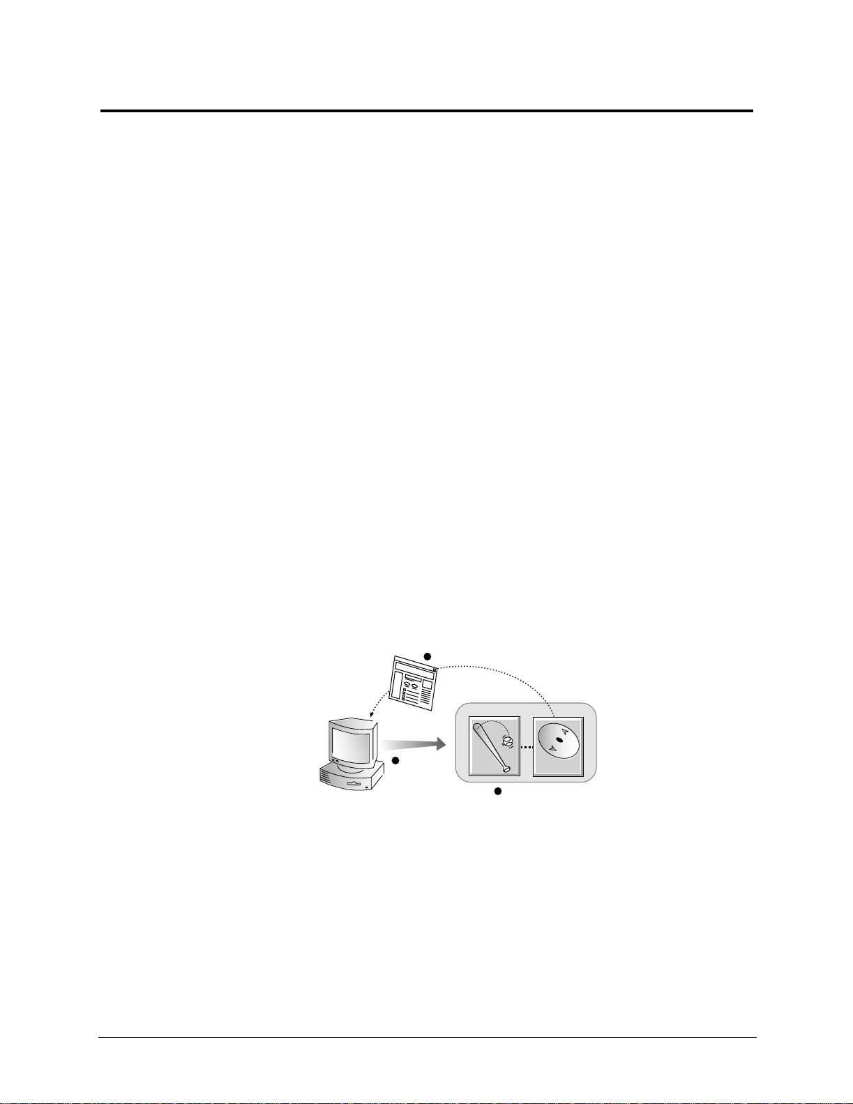
1Overview
Welcome to a faster network.
Traffic Server speeds Internet access, enhances web site performance, and delivers unprecedented web
hosting capabilities.
This chapter discusses the following topics:
• What is Traffic Server?‚ on page 1
• Traffic Server deployment options‚ on page 1
• Traffic Server components‚ on page 3
• Traffic analysis options‚ on page 5
• Traffic Server security options‚ on page 5
IMPORTANT The paths to files used in the manual are the following:
For Command files:
For Configuration files: /home/TS4/<version>/config
For Log files: /home/TS4/<version>/logs
In each path reference, replace <version> with the version number that was installed
in the
/home/TS4/<version>/bin
/home/TS4 directory.
What is Traffic Server?
The dream of global data networking has come true. Internet users request billions of documents each day all
over the world. Unfortunately, this dream ofglobal data networking has become a nightmarefor information
systems professionals as they struggle with overloaded servers and congested networks, trying to keep pace
with society’s growing data demands.
Traffic Server is a high-performance web proxy cachethat improves network efficiency and performance by
caching frequently accessed information at the edge of the network.This brings content physically closer to
end users for faster delivery and dramatically reduces bandwidth usage.
Traffic Server is designed to improve content delivery for enterprises, Internet Service Providers (ISPs),
backbone providers, and large intranets by m aximizing existing bandwidth.
Traffic Server deployment options
Traffic Server can be deployed i n different ways to best suit your needs and your environment:
• As a web proxy cache
• As a reverse proxy
• In a cache hierarchy
• In a T raffic Server cluster
The following sections provide a summary of the Traffic Server deployment options.
1
Page 14

Chapter 1 Overview
TrafficServerasawebproxycache
As a web proxycache, user requestsforweb content go to Traffic Server on theway to the destinedwebserver
(origin server). If Traffic Server containsthe requested content, it serves it directly. If Traffic Server does not
have the requested content, Traffic Server acts as a proxy, fetching the content from the origin server on the
user’s behalf, while keeping a copy to satisfy future requests.
Traffic Server provides two proxy caching options:
• Transparent proxy caching, where user requests are automatically injected into a Traffic Server cache on
their way to the eventual destination. Users request Internet content as u sual without any browser
configuration and Traffic Server automatically serves their requests. The user’s client software (typically
abrowser)isunaware thatit iscommunicatingwith Traffic Server. Transparentproxycaching isdescribed
in more detailin Chapter 3‚ Web Proxy Caching.
• Explicit proxycaching,where the user’s client software must be configuredto sendrequestsdirectly to the
Traffic Server.
Traffic Server as a reverse proxy
As a reverse proxy, T raffic Server is configured to be the origin server the user is trying to connect to (the
origin server’s advertised host name resolves to Traffic Server, which is acting as the real origin server). The
reverse proxy feature is also called server acceleration. Reverse proxy is described in more detail in Chapter
5‚ Reverse Proxy and HTTP Redirects.
Traffic Server in a cache hierarchy
Traffic Server can participate in flexible cache hierarchies, where Internet requests not fulfilled in one cache
can be routed to other regional caches, taking advantage of the contents and proximity of ne arby caches.In a
hierarchy of proxy servers, Traffic Server can act either as a parent or child cache, eitherto other Traffic
Serversor to other caching products.
Traffic Server supports the standard Internet Cache Protocol (ICP) to interoperate with existing ICP cache
hierarchies.
Hierarchicalcaching is described in more detail in Chapter 7‚ Hierarchical Caching.
Traffic Server in a cluster
Traffic Server scales from a single node into multiple nodes that form a cluster allowing you to improve
system performance and reliability. Traffic Server detects the addition or removal of nodes automatically. If
Traffic Server’s virtual IP failover option is enabled, Traffic Server maintainsa pool of virtual IP addresses
that it assignsto the nodes of the cluster. Traffic Server can detect ha rd node failures (such as power supply
or CPUfailures) andreassignIPaddressesof the failednodeto the remainingoperationalnodesautomatically.
Traffic Server has two clustering modes:
• Management-only mode, where you can administerall the nodesin a cluster at the same time. Nodes
automaticallyshare configuration information.
• Full-clustering mode, where the node caches act as a single aggregate cache. A T raffic Server cluster
distributesits cacheacrossits nodesintoasingle, virtualobjectstore,rather thanreplicatingthecache node
by node.
A fullyclustered TrafficServer providesasinglesystemimageto both users and administrators,appearing
as a single virtual server. Full-clustering mode includes management-only mode.
Traffic Server clusters are described in more detail in Chapter 6‚ Traffic Server Clusters.
2
Page 15

Chapter 1 Overview
Traffic Server com pon ents
Traffic Server consists of several components that work together to form a web proxy cache you can easily
monitor and configure. The main components are described below.
The Traffic Server cache
The Traffic Server cache consists of a high speed object database called the object store. The object store
indexesobjectsaccording toURLsandassociatedheaders.Usingsophisticatedobjectmanagement,theobject
store can cache alternate versions of the same object, varying on spoken language or browser type, and can
efficientlystoreverysmall andverylarge documents, minimizingwastedspace.Oncethecache beginstofill,
the Traffic Server mobilizes garbage collectors to remove staledata,ensuringthat the most requested objects
are kept on-hand and fresh.
Traffic Server is designed to tolerate total diskfailureson any of the cache disks. If the disk fails completely,
TrafficServerm arks the entirediskas corrupt and continuesusing theremaining disks.Ifallof the cache disks
fail, Traffic Server goesinto proxy-only mode.
You can partitionthe cachetoreservea certainamountofdiskspace for storing dataforspecific protocolsa nd
origin servers.
The Traffic Server cache is described in more detail in Chapter 8‚ Configuring the cache.
RAM cache
Traffic Server m aintains a small RAM memory cache of extremely popular objects. This RAM cache serves
the most popular objects as fast as possible and reduces load on disks, especially during temporary traffic
peaks. You can configure the RAM cache size to suit yourneeds.
The Adaptive Redirection Module (ARM)
The Adaptive Redirection Module (ARM) is used in transparent proxy caching to redirect intercepted user
requests destined for an origin server to the Traffic Server. Before the traffic is redirected by the ARM, it is
interceptedbyanL4switchorrouter.
To redirect user requests to Traffic Server,the ARM changes an incoming packet’saddress. The packet’s
destination IP address is changed to the IP addressof Traffic S erver and the packet’s destination port is
changed according to the protocol used. For example, for HTTP, the packet’s destination port is changed to
Traffic Server’s HT TP port (usually 8080).
The ARM supports automatic bypass of sites that do not function properly with proxy caches.
Traffic Server can respond to client request overloads by forwarding requests directly to origin servers. This
feature is called load shedding. Overload conditions, such as network outages, misconfigured routers, or
security attacks, can slow down Traffic Server’s response time. In transparent configurations, Traffic Server
can use its ARM bypass functionality to forward overload requests directly to origin servers, bypassing the
cache. When the overload condition dissipates, Traffic Server automatically returns to full caching mode.
The Host Database
The Traffic Server host database stores the Domain Name S erver (DNS) entries of origin servers to which
Traffic Server connects t o fulfill user requests. This information is used to adapt future protocol interactions
to optimize performance.
Among other information, the host database tracks:
• DNS information (for fast conversion of host names to IP a ddresses)
• The HTTP version of each host (so advanced protocol features can be used with hosts running modern
servers)
3
Page 16

Chapter 1 Overview
• Host reliability and availability information (to avoid making the user wait for non-functional servers)
The DNS Resolver
Traffic Server includes a fast, a synchronous DNS resolver to streamline conversion of host names to IP
addresses. Traffic Server implements the DNS resolver natively, directly issuing DNS command packets,
rather than relyingon slower,conventional resolverlibraries. Many DNS queries can be issued in parallel and
a fast DNS cache maintains popular bindingsin memory, significantly reducing DNS traffic.
Traffic Server processes
Traffic Server c ontains three processes that work together to process Traffic Server requests and manage,
control, and monitorthe health of the Traffic Server. The three processes are described below:
• The
traffic_server process is the transactionprocessingengine of Traffic Server. It is responsiblefor
accepting connections, processing protocol requests, and serving documents from the cache or origin
server.
• The
traffic_manager process is the commandandcontrolfacilityofthe Traffic Server, responsiblefor
launching, monitoring, and reconfiguring the
traffic_server process. The traffic_manager
process is also responsible for T raffic Manager,the proxy auto configuration port, the statistics interface,
cluster administration, and virtual IP failover.
traffic_manager process detectsa traffic_server process failure, it instantly restarts the
If the
process but also maintains a connection queue of all incoming requests. All incoming connections that
arrive in the several seconds before full server restart a re saved in the connection queue and processed in
first-come, first-served order. This connection queueing shields users from any server restart downtime.
• The
traffic_cop process monitorsthe health of both the traffic_server and traffic_manager
processes. The traffic_cop process periodically (several times each minute) queries the
traffic_server and traffic_manager process by issuing heartbeat requests to fetch synthetic web
pages. In the event of failure (if no response is received withina time-out interval or if an incorrect
response is received),
traffic_cop restarts the traffic_manager and traffic_server processes.
Figure 1-1. illustrates the three Traffic Server processes.
crontab process ensures
that traffic_cop process
is running
Traffic
Server
Processes
traffic_cop
traffic_server
Traffic Server Node
operating
system
traffic_manager
Figure 1-1. Traffic Server processes
4
Page 17

Chapter 1 Overview
Administration tools
Traffic Server offers several administration alternatives to suit the needs of many environments:
• T raffic Manager User Interface (UI) isa web based interfaceconsisting of a seriesofweb pagesaccessible
through a browser. Traffic Manager provides a rich set of graphs and statistical displays for monitoring
Traffic Server pe rformance and network traffic, a nd a set of options for configuringand fine-tuning the
Traffic Server s ystem. Traffic Manager offers password-protected, SSL-encrypted, single-point
administrationfor an entire Traffic Server c luster.
• The Traffic Line command-line interface is a textbased interface that provides equivalent functionality to
that of Traffic Manager. From the command line, you can e xecute individual commands or script a series
of commands in a shell.
• Various Configuration files allow complete administration through a simple file editing and signal
handling interface. You can change configuration optionsby editing configuration files manually instead
of usingTrafficManageror TrafficLine.(Anychangesyoum ake through Traffic Manager orTrafficLine
are automatically made to the configuration files.)
Traffic analysis options
Traffic Server provides several options for network traffic analysis and monitoring:
• Traffic Manager statistics and graphs show network traffic information. You can view graphs and
statistics from Traffic Manager or collect and processstatistics using the command-lineinterface, Traffic
Line.
• MRTG (Multi Router Traffic Grapher) is a graphing tool that provides a variety of graphs showing
historicalinformation about virtual memory usage, client connections,documenthit rates,and so on. You
can access MRTG from Traffic Ma n ager.
• SNMP Network Management support letsyoumonitorandm anage Traffic Server throughSNMPnetwork
management facilities. TrafficServersupports two management informationbases(MIBs): MIB-2, a well
known standard MIB, and the HP proprietary Traffic Server MIB that provides more specific node and
cluster information.
• TrafficManageralarms are presentedinTrafficManager.TrafficServersignalsanalarmfor any detected
failure condition. You can configure Traffic Server to send E-mail or page support personnel when an
alarm occurs.
• Transaction logging lets you record information in a log file about every request that Traffic Server
receives and every error it detects. By analyzingthelog files,you can determine how many people use the
TrafficServercache, how muchinformatione ach person requested,andwhatpagesare most popular. You
canalsosee why aparticulartransactionwasin error andwhatstate theTrafficServerwasin at a particular
time. For example, you can see that Traffic Server was restarted or that cluster communication timed out.
Traffic Server supports several standard log file formats, suchasSquid and Netscape, and its own custom
formats. You can analyze the standardformat log files with off-the-shelf analysispackages.To help with
log file analysis, you can separate log filesso that they contain information specific to protocol or hosts.
Trafficanalysis options are described in more detail in Chapter 9‚ Monitoring Traffic. Traffic Server logging
options are described in Chapter 12‚ W orking with Log Files.
Traffic Server security options
Traffic Server provides numerous options that enable you to establish securecommunication betweenthe
Traffic Server system and other computers on the network. Using the security options, you can:
• Control client access to the Traffic Server proxy cache.
• Control which hosts are allowed to access the Traffic Server machine (ARM security).
5
Page 18

Chapter 1 Overview
• Configure T raffic Server integration into your firewall and control trafficthrough a SOCKS server.
• Configure T raffic Server to use multiple DNS servers to match your site’s security configuration. For
example, you might choose to have Traffic Server use different DNS serversdepending on whe ther it
needs to resolve host names located inside or outside a firewall. This enables you to keep your internal
network configuration secure while continuing to provide transparent access to external sites on the
Internet.
• Use LDAP-based proxy authentication that enables you to leverage e xisting directory services by
supportingasynchronous match and bind requests to LDAP s ervers. This enables you to maintain policies
thatrequireusers to log in andbeauthenticatedbythe proxy before goingoutonto the Internet.Inaddition,
you can enable TrafficServerclients to access specificsiteson theInternetwithoutbeing authenticatedby
theLDAPserver.TrafficServer usesalocaldatabasetoimprovetheperformanceof LDAP authentication
and, upon completion, logs successfully authenticated users.
• Secure connections in reverse proxy mode betweena client and Traffic Server, and TrafficServer and the
origin server, using the SSL termination option.
• Control access to Traffic Manager using:
o SSL (Secure Sockets Layer) protection for encrypted, authenticated access
o An access control list (ACL) that defines which hosts are allowed to access Traffic Manager
o Administrator accounts that define which users can access Traffic Manager and which activities they
can perform (for example, view statistics only or view statistics and configure the Traffic Server)
• Set NNTP specific security options that:
o Control user access to ne ws articles cached by Traffic Server by defining access privileges for a
particular group of clients
o Enable external program-based NNTP authentication providing enterprise-wide control over new s
access, posting behavior, and other related privileges
Traffic Server security options are described in more detail in Chapter11‚ Security Options.
6
Page 19

2 Getting Started
You are now ready to begin using Traffic Server.
This chapter contains the following sections:
• Overview of Access Methods‚ on page 7
• Verifying that Traffic Server is up and running‚ on page 8
• Accessing Traffic Manager‚ on page 8
• Starting Traffic Line‚ on page 10
Overview of Access Methods
The instructionsin this guide refer to different methods of a ccessing the functionalityof the cache appliance.
As a general rule all tasks should be accomplished with Traffic Manager since it has the mostintuitive user
interface and automates many of the administrative tasks that would otherwise have to be completed
manually. The access methods are as follows:
1. Traffic Manager. Traffic Manager is a web-based tool that will allow customization of most aspects of
the cache appliance functionality. This is the preferred method for working with Traffic Server. Traffic
Manager can be accessed by a client web browser directed to the URL
http://<ip.address.of.appliance>:<adminport>
configuration as described in the HP Web Cache Server A ppliance Getting Started Guide. The
adminport is configurable, but will be 8081 after initial configuration until a different port is manually
specified. The user will be prompted for a user name and password, which are both admin after initial
configuration unless manually specified otherwise.
. T he IP address of the appliance was set during the initial
2. General Telnet access. By using telnet to access the appliance with the Telnet access user name and
password entered during the appliance initial network configuration session, you will be presented with a
menu listing a number of configuration and maintenance tasks. There are some Traffic Server
configurationtasks that require shellaccess to the cacheappliance filesystem, and youwillhavetoselect
shell access from the menu to complete these tasks. Instructions in this guide include T raffic Manager
instructions as well as manual editing of c onfiguration files throughshell access for completeness;
however, it is highly recommended that Traffic Manager be used whenever possible.
3. Telnet access to the appliance initial network configuration utility. T his is covered i n the HP Web
Cache Server Appliance Getting Started Guide. If you telnet into a previously unconfigured appliance or
an appliance that has just been reset to factory defaults with a user nameof hpsaconfig a nd a passwordof
hpsa, you will access the appliance initial network configuration utility where you can enter the IP
addresses for the LAN adapters, c onsole user name and password. After successfully completing the
appliance initial network configuration task, the
the appliance with the console user name and password you entered during the initial network
configuration.
4. Serial port access for initial configuration. T his is covered in the HP Web Cache ServerAppliance
Getting Started Guide. This allows a user to initially access the cache appliance before it has any IP
addressto perform initialnetwork setup.
hpsaconfig user will be deleted and you must access
7
Page 20

Chapter 2 Getting Started
Verifying that Traffic Server is up and ru nning
When youcompletedtheinitial configurationof the cache applianceasdescribedintheHPW eb Cache Server
Appliance sa2100/sa2200 Getting Started Guide, Traffic Server was automatically started.
To verify that Traffic Server i s up and running:
1. Access Traffic Manager (refer to Overview of Access Methods‚ on page 7).
2. From the Monitor tab, click the Protocols button.
3. Make a note of the current HTTP ClientTotal Document Bytes statistic.
4. Set your browser proxy setting to the Traffic Server name and proxy port.
5. Browse the internet.
6. Recheck the HTTP Client Total Document Bytes statistic.
This value increases as Traffic Server processes HTTP requests.
Accessing Traffic Manager
Traffic Manager is Traffic Server’s browser-based user interface, consistingof a series of web pages. Traffic
Manager provides a rich set of graphs and statistical displays for monitoring Traffic Server performance and
network traffic, plus a set of optionsfor configuring and fine-tuning yoursystem. All common Traffic Server
configuration tasks should be performed using this UI.
You access Traffic Manager through your web browser.
To access Traffic Manager:
1. Open your web browser.
Traffic Manager requiresJava and JavaScript;be sure to enable Java and JavaScript in your browser.
NOTE Use the following
restricted access to Traffic Manager via SSL connections; otherwise, use the
standard
2. Type one of the following locations in your browser:
Standard
SSL https://nodename:adminport/
where nodename is the name of the applianceand adminport is the number assignedto Traffic Manager
port (the defaultvalue for adminport is 8081).
http address.
http://nodename:adminport/
https addressinstep 2 to reach Traffic Manager only if you have
8
Page 21
Chapter 2 Getting Started
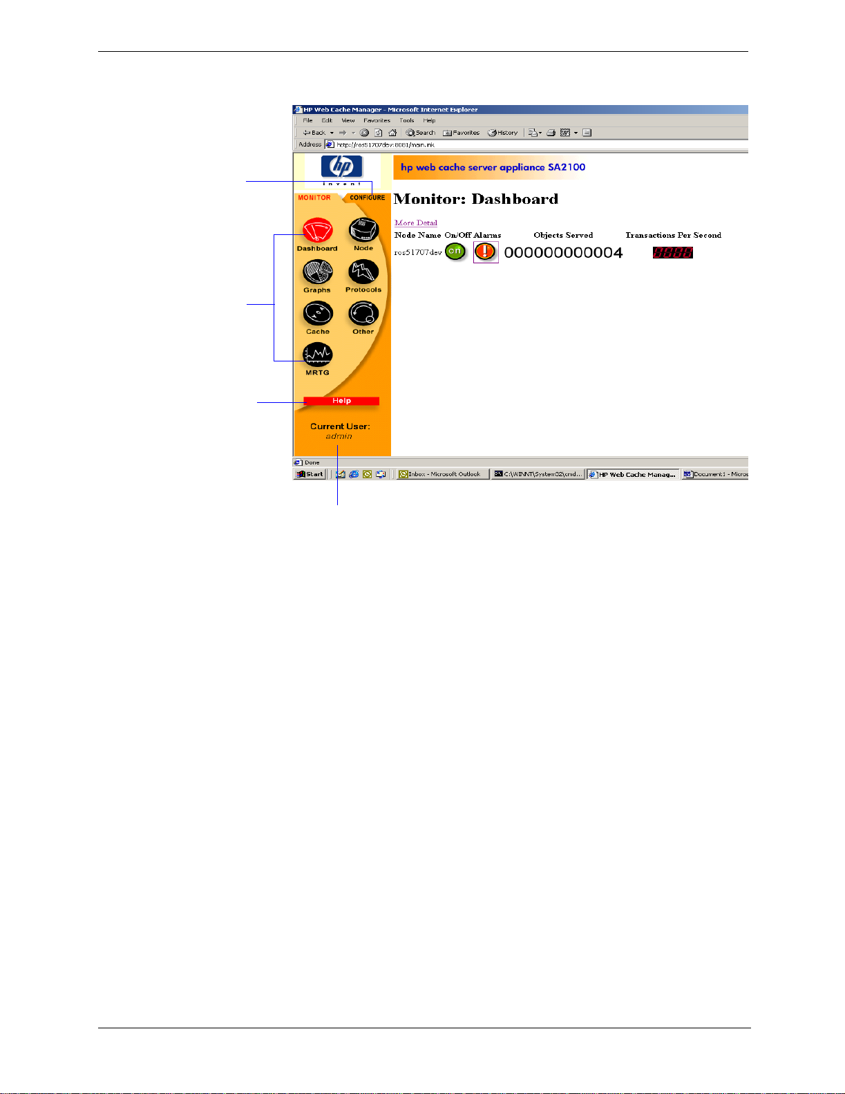
Traffic Manager opens in your web browser and displays the Dashboard, s hown in Figure 2-1.
Click the
Configure tab
todisplaythe
Configure
buttons and
set
configuration
The Monitor
tab contains
seven
buttons.
Click a
button to
display a
page of
Click the Help
button to
display a
description of
the current
page
This shows t he current
user loggedin to Traffic
Manager
Figure 2-1. Traffic Manager: The Monitor Dashboard
Using the Monitor and Configure tabs
Traffic Manager has two tabs:
• The Monitor tab lets you view Traffic Server performance and network traffic statistics. For more
information, refer to Viewing statistics from TrafficManager‚ on page 63.
• The Configuretabletsyou view and modifyTrafficServer’sconfigurationoptions.For more information,
refer to Appendix 10‚ Configuring Traffic Server.
By default, Traffic Manager starts by displaying the Monitor tab. To display the Configure tab, click the
Configure tab to the right of the Monitor tab.
Using online help
Both the Monitor and Configure tabs provide a Help button. When you click the Help button, the Traffic
Server online help opens in another browser window. The online help describes each page that opens when
you click a button on the Monitor or Configure tab.
9
Page 22

Chapter 2 Getting Started
Starting Traffic Line
Traffic Line is a text-based interface that can be accessed t hrough a Telnet session. You can use Traffic Line
to perform many of the tasks you can perform in Traffic Manager. For ease of use, it is recommended that
Traffic Manager be used unless a function only available in Traffic Line is required.
Traffic Line has two command-line modes:
• TrafficLinebatchmode
You can use the batchmode to execute individual commands or to script multiple commands in a shell.
Refer to Appendix C‚ Traffic Line Commands for a listof commands.
• TrafficLineinteractivemode
You can use interactive mode to retrieve statistics and to configure Traffic Server. TrafficLineinteractive
mode consists of several levels of commands. The Traffic Line interactive levels consist of the same
commands available on Traffic Manager Monitor and Configure tabs.
To start a Traffic Line session:
1. Telnet into the HP web cache appliance and select Shell Access as described in Overview of Access
Methods‚ on page 7.
You are now ready to enter Traffic Line commands.
Traffic Line commands take the following form:
traffic_line -flag argument
2. For a list of traffic_line commands, enter:
traffic_line -h
3. To enter Traffic Line interactive mode, enter the followingcommand:
traffic_line -i
For information about monitoring Traffic Server using Traffic Line interactive mode, refer to Viewing
Statistics from Traffic Line‚ on page 68.
For informationabout configuringTrafficServer usingTrafficLine interactive mode,referto Configuring
Traffic Server using Traffic Line‚ on page 76.
Restarting Traffic Server
Various procedures throughout thismanual instruct you to restart Traffic Server.
YoucanrestartTrafficServer by scrollingto the Web ManagementsectionoftheServer BasicspageinTraffic
Manager, and click the restart button. (For more information, see Configuring Traffic Server using Traffic
Manager‚ on page 73.)
10
Page 23
3 Web Proxy Caching
The idea behind web proxycaching is to store copies of frequently accessed documents close to users and
serve this information to them on demand.Internet users get their information faster and Internet bandwidth
is freed up for other tasks.
This chapter discusses the following topics.
• Understanding web proxy caching‚ on page 11
• News article caching‚ on page 16
Understanding web proxy cach ing
Internet users direct their requests to web servers all over the Internet. For a caching server to serve these
requests,itmustactasaweb proxy server. A web proxy server fields user requests to arbitrary web servers
and either servesthe requests, or forwards them on to the origin server (the web server that contains the
original copy of the requested information).
The Traffic Serverproxy supportsboth transparentproxyc aching, where the user’s client software (typically
a browser) is unaware that it is communicating with a proxy, and explicit proxy caching, where the user’s
client software must be configured to send requests directly to the traffic Server proxy.
A day in the life of a cache request
Here is an overview of the steps that take place as a Traffic Server proxy cache serves a user request.
1. Traffic Server receivesa user request for a document, image, news article, or other web object.
2. With the object address in hand,TrafficServerlooksup therequested object in its objectdatabase(cache).
3. If the object is in the cache, Traffic Server checks to see if the object is fresh enough to serve. (See
Ensuring cached object freshness‚onpage 12 for details.) If the objectis fresh, Traffic Server serves it to
the user as a cache hit (Figure 3-1.).
returned document
3
Traffic Server
request
1
client
Figure 3-1. A cache hit
hit
2
a cache hit
local
cache
4. If thedata in thecacheisstale,T raffic Server connects to the origin server and asks if the document is still
fresh. If the document is stillfresh, Traffic Server sends the cached copy to the user immediately.
11
Page 24

Chapter 3 Web Proxy Caching
5. If the object isnotinthecache (a cache miss)or the serverindicates thatthecached copy isnolongervalid,
Traffic Server gets the document from the origin server, simultaneously streaming i t to the user and the
cache (Figure 3-2.). Subsequentrequests for the object will be served faster.
3
Traffic Server simultaneously caches
and serves the document to the client
origin
server
client
request
1
Traffic Server
miss
local
cache
2
a cache miss
Figure 3-2. A cache miss
Caching is more complex than the preceding overview suggests. In particular, the overview does not answer
these questions:
• How does Traffic Server ensure freshness?
• How does Traffic Server serve correct HTTP alternates?
• How does Traffic Server treat requests for objects that cannot or should not be cached?
The following sections discuss these questions.
Ensuring cached object freshness
Traffic Server ha ndles object freshness differently depending on protocol.
HTTP Web documents support optional author-specified expiration dates. Traffic Server adheres
to these expiration dates; otherwise it picks an expiration date based on how frequently the
document is changingand on administrator-chosen freshness guidelines. In addition,
documents can be revalidated, checking with the server if a document is still fresh.
FTP FTP documents s tay in the cache for a time period s pecified in the Freshness section of
the Cache page in Traffic Manager’s Configure Mode.
NNTP News articles are refreshed each time Traffic Server polls parent news servers for c hanges
in group lists, article overview lists, and article updates. See Maintaining the cache:
updates and feeds‚ on page 19.
Revalidating HTTP objects
If an HTTP object is stale, Traffic Server revalidates the object. A revalidation is a query to the origin server
that asks if the object is unchanged. The result of a revalidation could be:
• The object is still fresh; Traffic Server resets its freshness limit and serves the object.
• A new copy of the object is available; Traffic Server caches the new object,replacing the stale copy, and
serves the objectto the user simultaneously.
• The object no longerexists on the origin server; Traffic Server does not serve the cached copy.
• The origin server does not respond to the revalidation query. The Traffic Server s erves the stale object
along with a
111 Revalidation Failed warning.
12
Page 25

Chapter 3 Web Proxy Caching
HTTP object freshness tests
Here is how Traffic Server determines an HTTP document’s freshness:
Expires header test. Some documents come with Expires headers or max-age headers that e xplicitly
define how long the document may be c ached. A simple comparison of the current time with the e xpiration
time tells T raffic Server whether or not the document is fresh.
Last-Modified / Date header test. If there is no expiration information, a freshness limit can be estimated
from the
document was modified. If a document was last modified two years ago, it is unlikely to suddenlychange, so
Traffic Server can cache it safely for a while.B ut ifthedocument just changed 5 minutes ago, it’s likely to be
volatile,and Traffic Server should not cache it forlong.TrafficServer uses a formula to determine the length
of time it considers a stored object to be fresh. Traffic Server stores an object for s ome percentage (F) of the
time that elapsed since it last changed, 10% by default:
Where the Date header provides the date the object was sent to Traffic Server, and the Last-Modified
header provides the date the object was last modified on the origin server.
For example, if a document was last m odified 32 days ago and was sent to Traffic Server 2 days ago, it is
considered fresh in cachefor 3 days after it was sent, assuming a factor of 10%. It is considered fresh for one
more day.
Because this method might select large freshness times for documents that have not changed for a long time,
cache administratorsmaywant to place an upper boundary on the freshness limit. The freshness limit, then, is
the minimum of this upper boundary and the computed freshness limit.You configure this upper boundary in
the Freshness sectionof the Configure:Cachepageof TrafficManager. (Minimum freshness information
for a document to be cacheable is one of the configuration options under Freshness.)
Default test. For documents that do not have Expires headers or do not have both Last-Modified and
Date headers, you can specifyan absolute freshness limit in t he Freshness section of the Configure: Cache
page.
Revalidate rules in the cache.config file. Revalidate rules apply specific freshness limits to specific HTTP
or FTP objects. You can set freshness limits for objects originating from particular domains or IP addresses,
objects with URLs that contain specified regular expressions, objects requested by particular clients, and so
on. See cache.config‚ on page 162.
Last-Modified and Date headers. The Last-Modified header indicates how long ago a
freshnesslimit=F*(Date-Last-Modified)
Deciding whether to serve HTTP objects
Even though a document may be fresh i n the cache, clients or servers may have their own constraints that
prevent them from retrieving the document from the cache. For example, a client might request that a
document not c ome from a cache, or if it does, it cannot have been cached for more than 10 minutes.
Traffic Server bases the servability of a cached document on
Control
The following cache-control header fields affect whether objects are served:
• The
• The
• The
• The
headers can appear in both client requests and server responses.
no-cache field, sentbyclients,tellsTrafficServerto servenoobjects directly from the cache; always
revalidate. You can configure Traffic Server to ignore client
max-age field, sent by servers, is compared to the document age; ifthe age is less than the max-age,
the document is fresh and can be served.
min-fresh field, sent by c lients, is an acceptable freshness tolerance.The client wants the object to
be at least this fresh. If a cached document does not remain fresh at least this long in the future, it is
revalidated.
max-stale field, sent by clients, permits Traffic Server to serve stale documents provided they are
not too old. Some browsers may be willing to take slightly old documents in exchange for improved
performance, especially during periods of poor Internet availability.
Cache-Control header fields. Cache-
no-cache fields.
13
Page 26

Chapter 3 Web Proxy Caching
Traffic Server applies Cache-Control servability criteria after HTTP freshness criteria. For example, a
document might be considered fresh, but if its age is greater than its
max-age, it is not served.
Configuring HTTP freshness options
You can configure the following freshness guidelines for Traffic Server:
• How oftentorevalidate(whentoconsiderobjectsstale). See Configuring HTTP revalidation‚on page 14.
• Whether to cache documents without freshness information. See ConfiguringHTTP cachability‚ on
page 14.
• The upper boundary used to determine if the Last-Modified /Date freshness limit is too long.
• The absolute freshness lifetime used to estimate the freshness of documents without
Modified
cache.config file,you can configure Traffic Server to revalidate objects from specific origin servers
In the
headers.
at specific times. Refer to cache.config‚on page 162.
Configuring HTTP revalidation
The following HTTP revalidation options are available:
• Always revalidate(everythingis considered stale).
• Never revalidate (everything is considered fresh).
• Revalidate all objects without
by first checking the
Expires header, and then checking Cache-Control headers.
• E valuate freshness as follows:
1. Use the
Expires header test, if applicable,otherwise go tostep 2. If the object is stale, revalidate. If
it is fresh, check the
2. Use the
according to the
Last-Modified / Date header test, if applicable, otherwisegoto step 3. If the object is fresh
Last-Modified / Date test, check the Cache-Control headers for any freshness
restrictions.
3. Use the absolute freshness limit specified in the Freshness section of the Configure: Cache page.
Revalidate if the age is past the freshness limit.
Configuring HTTP cachability
Expires or Last-
Expires headers. Evaluate the freshness of objects with Expires headers
Cache-Control headers.
The following HTTP cachability options are available:
• Cache only documents that have
• Cache only documents that have
• Do not restrict caching
Caching HTTP alternates
Some origin servers answer requests to the same URL with a variety of objects. The content of these objects
can vary widely, according to whe ther a server delivers content for different languages, targets different
browsers with differentpresentation styles,or deliversvariablec ontent at different times of the day.Different
versions of the same object are called alternates.
Expires headers
Expires or Last-Modified headers
14
Page 27

Chapter 3 Web Proxy Caching
Alternates are identified by header information. You can configure Traffic Server to cache a ll alternates
according to a particular header. For example, if you tell Traffic Server to vary on the
User-Agent header,
Traffic Server c aches all the different user-agent versions of documents it encounters. You configure the
cachingof alternates in the Variable Content section of t he Cache page in Traffic Manager’s Configure
mode.
To cache or not to cache?.
NNTP You can limit article caching to specific news groups. See Blocking particular groups‚ on
page 18.
FTP You can specify never-cache rules for specifictypes of FTP documents in the
cache.config fi le. See cache.config‚ on page 162.
HTTP Traffic Server responds to caching directives from clients and o rigin servers, as well as
configurable options inTraffic Manager and the
The following table lists the HTTP caching directives that Traffic Server follows.
Directive source Caching directives
administration
options
Traffic Server has the following administration options for caching:
• Configure Traffic Server not to cache objects with URLs containing the
following:
?
;
/cgi
.asp
end in
• Configure Traffic Server not to cache objects served in response to the Cookie:
header.
• Use never-cache rulesin the cache.config file. Refer to cache.config‚ on
page 162.
client Traffic Server does not cache objects with the following request headers. Note that
some of these directives can be overridden by Traffic Server administration options.
• Cache-Control: no-store header
• Cookie: header
• Authorization: header
origin server TrafficServerdoes not cache objects with the following response headers. Note that
some of these directives can be overridden by Traffic Server administration options.
• Cache-Control: no-store
• www-Authenticate: header
• Set-Cookie: header
• Cache-Control: no-cache header
• Pragma: no-cache header
• Expires: header with value of 0 (zero) or a past date
cache.config file.
15
Page 28

Chapter 3 Web Proxy Caching
Scheduling updates to local cache content
To further increasethe performance of Traffic Server, you can configure it to perform scheduled updates to
the local cache content. This enables you to instruct Traffic Server to explicitly load specific objects into
cache. You might find this especially beneficial when using Traffic S erver as a reverse proxy for server
acceleration,enablingyou to preloadcontent thatyouanticipatewillbe in demand.SeeUnderstandingreverse
proxy caching‚ on page 33.
You do this by inputtinga list of URLs inthe Content Management page in Traffic Manager. This modifies
the
update.config file, specifying objects that you want to schedule for update along with the time and
interval of when this update should take place. The UI also enables you to specify a recursion depth for the
URL.
Traffic Server uses this information to determine the URLs for which it is responsible and, for each URL,
derives all recursive URLs if applicable. It then generates a unique,sorted URL list. Using this list, Traffic
Server initiates an HTTP
limits for HTTP concurrency at any giventime. The system logs the completion of allHTTP
GET for each un-accessed URL, ensuring that it remains within the user-defined
GET operations,
enabling you to monitor the performance of this feature.
News article caching
Traffic Server c an function as a news server or a caching news server. T his section provides background
information about Traffic Server news server and the Ne twork News Transfer Protocol (NNTP) caching
features.
News, alsoknownasUSENETanddiscussions, isa systemofonlinediscussion groups. NNTP is theprotocol
used to retrieve and distribute these discussion groups. News groups exist to discuss just about any subject;
for example,
rec.humor, talk.religion, news.answers, rec.food.recipes,andcomp.std.unix.
The articles posted to these groups are propagated around the world. Traffic Server supports NNTP as
specified in RFC 977 and many common extensions and proposed extensions.
To read news articles, users need a news reader, such as Netscape Communicator or Microsoft Internet
Explorer, and a ccess to a news server. Traffic Server is a caching news server. It can be configured tosit
transparently between users and a parent or backing news server, increasing responsiveness for the user and
decreasing network bandwidth use and the load on the parent news server.
Traffic
Server
users
Traffic
Server
Parent
NNTP
users
Figure 3-3. Traffic Servers caching news articles for a distant NNTP server
Server
16
Page 29

Chapter 3 Web Proxy Caching
Traffic Server provides many configurable options for supporting parent NNTP servers. The following
sections describe Traffic Se rver’s NNTP features.
Traffic Server as a news server
When clients want to read news, they access a news server. The news server offers a list of groups to which
clients can subscribe. For each subscribed group, the clients read an overview list of the articles in the group,
and then select an articleto read. When Traffic Server acts as a news server,it:
• Maintains lists of supported news groups
• Accepts news feeds for each supported news group
• Serves requested articles to users
• Accepts and numbers user postings to its supported news groups
Traffic Server as a caching proxy news server
When Traffic Serveracts as a caching proxy news server for a particular news server,it:
• Maintains l ists of the news groups on its parent NNT P servers. You c an configure the frequency that
Traffic Server updates its copies of group lists.
• Caches and serves article overview listson demand. You can also tell Traffic Server to pull article
overview lists from the parent ne ws server periodically.
• Caches and serves articles on demand. Traffic Server can also accept news feeds, like any news server.
• Caches and serves miscellaneous LIST files, such as subscription files.
• Sends user postings to the parent news server.
When clients issue news requests, Traffic Server intercepts these requests and serves them from its cache,
reducing traffic to parent news servers. If a particular overview or article is not in the cache, Traffic Server
forwards requests to the parent server.
Supporting several parent news servers
TrafficServercancache articles forseveralnewsservers. You specifyallof the parent news serversforTraffic
Server in the
server, you can have Traffic Server cache some or all of that server’s news groups.
Some of the possible parent configurations that T raffic Server supports are as follows:
Several news servers supplying the same groups
Several news servers can be configured to redundantly serve the same groups, providing enhanced reliability.
Traffic Server provides the following features for managing these configurations:
• Priorities
nntp_servers.config file. See nntp_servers.config‚ on page 177. For each parent news
If TrafficServerhastocontact a parentnewsserver for informationabout a group suppliedby severalnews
servers, TrafficServer contacts the news server with the highest priority.
• Round-robin
If several parent news servers supplying the same group have the same priority, Traffic Server selects a
parent news server in round-robin fashion.
• Failover
If a request to a parent server fails, Traffic Server tries the next server in the round-robin (of the same
priority), and then servers of lower priority.
17
Page 30
Chapter 3 Web Proxy Caching
y
• Background re tries
Failed servers a re retried in the background and are used (restored to their specified priority) when they
become available.
Several servers supplying different groups
Several news servers can be configured with news servers supplying different (disjoint) groups.
Administrators can use this feature to spread the load based on group.
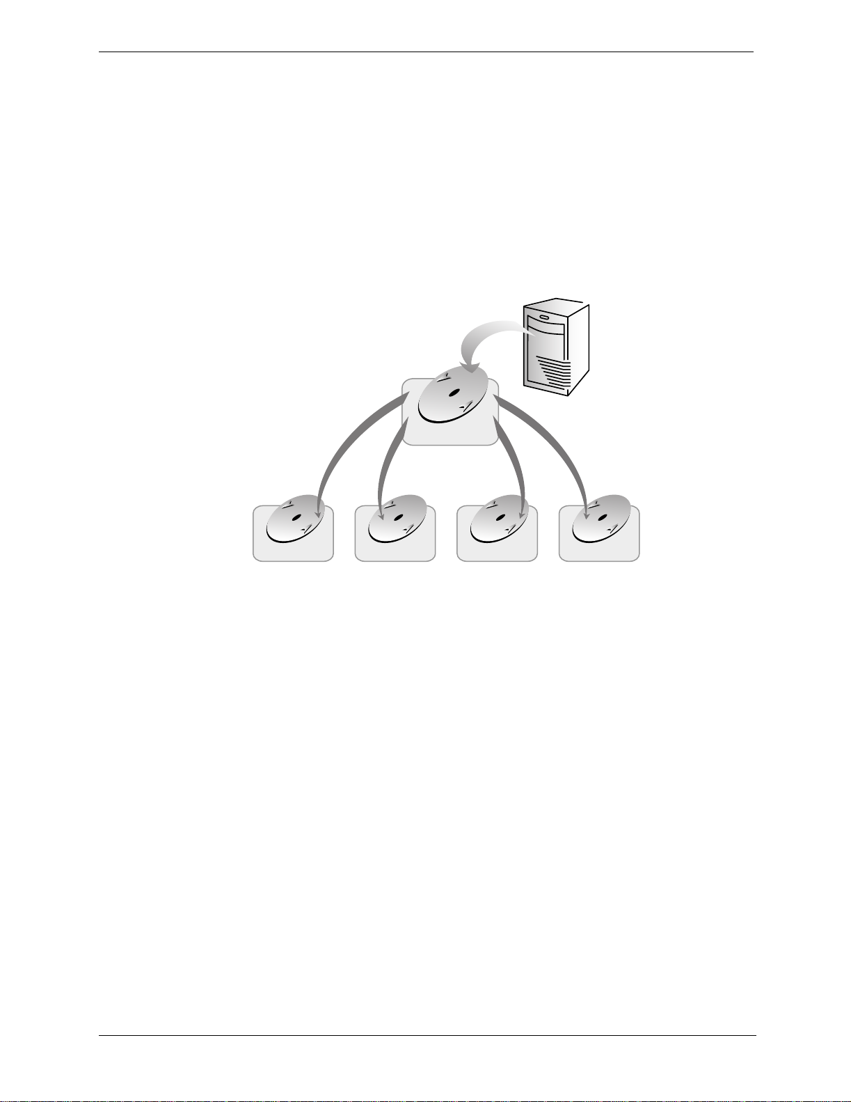
NNTP cache hierarchies
Using a TrafficServer as parent to a groupof Traffic Serverscanreduceloado n aparentnewsserverandtake
advantage of the large number of concurrent connections Traffic Server supports.
Bomba
Parent
Traffic Server
Parent Cache
Zurich
NNTP
Server
London
Traffic Server Child Caches
Figure 3-4. Hierarchy of news caching servers
In Figure 3-4. above, the parent news server for each of the child Traffic Servers isthe parent Traffic Server.
The parent Traffic Server is a child cache to the distant parent news server.
Nonstandard ports and network interfaces
You can configure the interface from which to connect to a parent news server port. You can also configure
the port on the parent server to which Traffic Server connects.
Blocking particular groups
You can block particular groups on specified news servers.Clientsdo not see blocked groups in news server
group lists. You list all blocked groups in the
Clustering
Articles, overview lists, group lists, and LIST files are all m aintained in HP ’s high performanceobject store.
This information is updated at configurable intervals so that users and child caches see a consistent view of
news.
Large clusters of Traffic Servers can be configured to act as a single l arge virtual cache with all the storage
and serving power of the aggregate. See Chapter 6‚ Traffic Server Clusters. Article numbers and group
information are maintained consistently across the cluster.
Paris Madrid Oslo
nntp_servers.config file; see page 177.
18
Page 31

Chapter 3 Web Proxy Caching
Transparency
NNTP traffic bound for a well known NNTP server can be intercepted transparently by Traffic Server. By
transparently intercepting, caching, and serving the NNTP data from a centralized parent news server, Traffic
Server simplifies migration and administration while increasing responsiveness and decreasing network
utilization.
Transparency mode is installed by default during Traffic Server installation. See the HP Web Cache Server
Appliance Getting Started Guide for more information. Once installed, you will need to configure and enable
it to be able to use it.
Posting
Traffic Server sends user article postings to the parent news server. You can specify the parent news server
thatreceivespostings foraparticulargrouporset of groups in the
When Traffic Serveractsas the news server (accepting articlefeeds), Traffic Server accepts postings.
With background posting, the Traffic Server queues posted articles until the posting news server can accept
the posted article.
nntp_servers.config file;see page 177.
Maintaining the cache: updates and feeds
Traffic Server can maintain the freshness of its cache by:
• Updating its cache on demand
• Actively retrieving (pulling) updates a t configurable intervals
• Accepting news feeds
nntp_servers.config filecontrols theTrafficS erver’s caching behaviorfor specific news groups;see
The
page 177form ore information.YouconfigureupdatefrequenciesintheConfigure: ProtocolspageofTraffic
Manager. Here a re the available options:
• Pull the overview information for specified groups
For allgroupsdesignated as pullover,theserverwillretrieve the overview databaseinformation(using the
OVER/XOVER c ommands) automatically and periodically.
Pulling overview information can be useful for high volume groups which are frequently read but from
which only a subset of the articles are accessed.
• Pull the articles for specified groups
For all groups designated as pull, Traffic Server retrieves the articles automatically and periodically.
Pulling groups is useful when the administrator does not wish to or cannot set up a full or partial feed.
• Dynamically subscribe to specified groups
Traffic Servercanmonitortheusagepatternforgroups, and those for which the overview databaseis very
frequently accessed can be treated as pullover groups. Likewise those for which the articles are very
frequently accessed can be treated as pull groups.
• T ake a partial feed (push) for specified groups
For all groups designated as push, Traffic Server verifies that it has any requested articles and retrieves
them from the parent server if they arenot available locally.
Partial feedsare useful for groups where some articles are always accessed, or for shifting article transport
to a time of da y when bandwidth is cheaper or underutilized.
19
Page 32

Chapter 3 Web Proxy Caching
• Take a full feed for some or all groups
For all groups designated as feed, Traffic Server does not connect to the parent news server, and instead
acts like a conventional news server.In particular,if a cache miss occurs,TrafficServer does not forward
the request to a parentnews server.
Full feeds can be used for very high volume groups in which most or all the articles are accessed or for
shifting article transport to a time when bandwidth is cheaper or more plentiful.
CAUTION Taking a full feed is not recommended as the server will have no way to retrieve an
article if it is lost for any reason (such as lackof space or hardware failure).
Configuring access control
Youcanconfiguredifferent typesofuser authenticationbased on sourcedomain,hostname, orIPrange.These
values are set in the
Option Description
Allow or deny You can simply allow or deny particular domains, hosts, or IP ranges.
Basic This option is simple authentication based on user name and optional password.
Generic Generic authentication allows a specified program on the authentication server
Custom An arbitrary program on the authentication server (which can be the Traffic
Authenticationserver An authentication server, possibly located on a different host machine, can be
Version 2 NNTP
authentication
nntp_access.config file. Here are the available options:
(which can be the Traffic Server host machine or a specified remote
authentication server) to communicate with an arbitrary program on the client
to do the authentication.
Server host machine or a specified authentication server) can be used to do the
authentication based on the client hostname, client IP, and optionally the client
user name and password.You canusecustomauthenticationtointerface Traffic
Server to any standard or homegrown access control mechanism.
used to do the authentication (generic and c ustom) This enables authentication
to be centralized.
Traffic Server supports version 2 NNTP authentication.Do not use this form of
authentication unless you are certain that all of your clients use version 2
authentication.
Using enhanced NNTP authentication
Traffic Server enables you to leverage your existing directory infrastructure to perform enhanced NNTP
authentication. You might consider using thisfeaturein cases where simple user authentication, based on
source domain, hostname, or IP range,is insufficient for the needs of your organization. For example, you
might need to base your NNTP access controlpolicies on factors such as time of day, system load, or other
dynamic characteristics.
Traffic Server supports enhanced NNTP authentication through the use of external programs, known as
plugins, which interface directly with your directory or database. You can write or script plugins using any
language that permits you to connect to a directory or database, including PERL and C, among others. You
can position them anywhere on the network, connected by a secure tunnel if required.
Each time a userneeds to be authenticated,TrafficServer connectsto the authenticationserver,which is part
of Traffic Server, and runs the plugin.
20
Page 33

Chapter 3 Web Proxy Caching
Obeying NNTP control messages
The Traffic Server default setup for nonfeed news groups is to periodically check the parent server for new
groups, cancelled articles, and new articles. If you have enabled these periodicchecks in the Configure:
Protocols page, you do not need to enable obeying controlmessages.
TrafficServercanbe configuredtoobeyNNTPcontrolmessages.In pa rticular, you can enable Traffic Server
to obey
For example, if you select “Obey cancel control messages,” Traffic Server pulls
cancel, addgroup,andrmgroup messages in the Configure:Protocolspage of Traffic Manager.
cancel messages
automatically in order to obey them.
Client bandwidth throttling
You can limit the amount of bandwidth allotted to clients for downloading articles. Clients that attempt to
exceed the bandwidth limit willhave each operation slowed in order to keep their bandwidth consumption to
the limit. You set the bandwidth limit (the client speed throttle) in the NNTP section of the Protocols page in
Traffic Manager Configure mode.
21
Page 34

4 Transparent Proxy Caching
The transparency option enables Traffic Server to respond to Internet requests without requiring users to
reconfigure their browser settings.
This chapter discusses the following topics.
• Serving requests transparently‚ on page 22
• ARM redirection‚ on page 22
• Interception strategies‚ on page 23
• Interception bypass‚ on page 28
Serving requests transparently
In non-transparent operations, client browsers must be configured to send web requests to the Traffic Server
proxy cache. Many sites have no direct control over user browser settings, making it necessary for site
administrators to tell users to configure their browsers to direct requests to a Traffic Server.
The transparency option enables Traffic Server to respond to Internet requests without requiring users to
reconfiguretheirbrowser settings.Itdoesthis by redirectingthetrafficflowintotheTrafficServercache after
it has been intercepted by a Layer 4 switch or router.
Here’s how Traffic Server transparent interception works:
1. Traffic Server intercepts client requests to origin servers. There are severalways to deploy Traffic Server
so that interception can take place. See Interception strategies‚ on page 23 for details.
2. HP’s Adaptive Redirection Module (ARM) redirectsrequests destined for origin servers to the Traffic
Server application. See ARM redirection‚on page 22 for details.
3. A very small number ofclientsand servers do not workcorrectlythrough proxies.TrafficServer identifies
these problem clients and servers dynamically, and the ARM adaptively disables interception for these
clients and servers, passing their traffic unimpeded to the origin server. Additionally, clients and servers
can be manually exempted from caching by configuring ARM. See Interception bypass‚ on page 28 for
more information.
4. Traffic Serverreceives and begins processing the intercepted client requests as explained in
Understanding web proxy caching‚on page 11. If a requestis a cache hit, Traffic Server serves the
requested document or news article. If a request is a miss, Traffic Server retrieves the document from the
origin server and serves it to the client.
5. On the way back to the client, the ARM changes the source IP addressto the origin server IP address and
the source port to the origin server port.
ARM redirection
The intercepted client requests that reach Traffic Server are addressed to an origin server. Traffic Server’s
ARM readdresses requests to Traffic Server so that they can be served.
TheARMcanmake two changestoan incoming packet’saddress: itsdestinationIPaddress anditsdestination
port. Typically, HTTP packet destination IPs and ports are readdressed with theIP address of T raffic S erver,
and Traffic Server’s HTTP proxy port (usually port 8080). NNTP packet destination IPs are readdressed with
the IP address of TrafficServer. If Traffic Server uses a portotherthan 119 for NNTP, the destinationNNTP
port is readdressed as well. You configure packet readdressing in the /home/TS4/<version>/config/
ipnat.conf file. This file contains redirection rules that specify how incoming packets should be
readdressed.
22
Page 35

Chapter 4 Transparent Proxy Caching
Interception strategies
Routing solutions enable transparent interception of Internet requests. The transparency routing solutions
supported by Traffic Server are:
• A Layer 4 switch.
See “Using a layer 4 switch with cache switching functionality to filter transparencyrequests” on page 23.
• A Cisco IOS-based router using the We b Cache Control Protocol (WCCP).
See Using a WCCP-enabled router for transparency‚ on page 24.
• Policy-based routing.
See Using policy-based routing to filter transparency requests‚ on page 27.
• Software routing.
See Interception bypass‚ on page 28.
How client requests reach Traffic Server depends on network topology. In a complex network, you must
decide which clientsareto be served transparentlya nd m ake surethatTraffic Server is positioned to intercept
theirrequests.TrafficServer, or routersor switchesfeedingTrafficServer,are oftendeployedat a major artery
or aggregationpipe to the Internet.
ARM is installed by default and must be activated to use transparency. The section “ARM redirection” on
page 22 describes configurationdetails.
Using a layer 4 switch with cache switching f unctionality to filter transparency requests
• Layer 4 switches have the ability to rapidly redirect supported protocols to Traffic Server, while passing
all other Internet traffic throughdirectly to its destination. Figure 4-1. below illustrates this scenario for
HTTP.
Internet
end users
Figure 4-1. Using a Layer 4 switch to filter HTTP requests
L4 switch
all
all
80
Traffic Server
23
Page 36

Chapter 4 Transparent Proxy Caching
Layer 4 switches offer the followingfeatures,depending on the particular switch:
• A Layer 4 switch that can sense downed hosts on the network and redirect traffic adds reliability.
• If a single Layer 4 switch feeds several Traffic Servers, the switch handles load balancing among the
Traffic Server nodes. Different switches might use differentload balancingmethods, such as round-robin
or hashing. If a Traffic Server node becomes unavailable, the switch automatically redistributes the load.
When the node returns to service, some switches automatically return the node to its previous workload,
so that the node c ache need not be repopulated; this feature is called cache affinity. HP recommends that
you do not enable Traffic Server virtual IP failover in this situation, because Layer 4 switch failover is
already in operation.
Using a WCCP-enabled router for transparency
Traffic Server supports WCCP 1.0 and WCCP 2.0.
A WCCP 1.0-enabled router can send all port 80 (HTTP) traffic to Traffic Server, as shown in Figure 4-2.
below. The Traffic Server ARM readdresses port 80 to Traffic Server’s proxy port (by default, port 8080).
TrafficServerprocesses therequestas usual, retrievingtherequested documentfromthec ache if it is a hit and
sending the response back to the client. Along the way, the ARM readdresses the proxy port in the response
headertoport80 (undoing thereaddressingitdid onthewayto Traffic Server).Theuser then sees theresponse
exactly as if it were sent directly from the originserver.
A WCCP 2.0-enabled router works in the same way as a WCCP 1.0-enabled router. In additionto port 80
(HTTP) traffic, WCCP 2.0 supports a dditional protocols including NNTP (port 119 traffic).
internet
end users
Figure 4-2. Using a Cisco IOS r outer to send port 80 traffic to several Traffic Servers
Cisco IOS router
all
Traffic Server 1
all
80
switch or hub
Traffic Server 2
Traffic Server 3
24
Page 37

Chapter 4 Transparent Proxy Caching
WCCP provides the following routing benefits:
• The WCCP-enabled router and Traffic S erver exchange heartbeat messages, lettingeach other know they
are running. The WCCP router automaticallyreroutes port 80 traffic (and port 119 traffic in WCCP 2.0) if
the Traffic Server goes down.
• If severalTrafficServersreceivetraffic from a WCCP router,WCCP balances the load among the Traffic
Servers. The group of T raffic Serversiscalleda WCCP cache farm.SeeAbout WCCP load balancing‚ on
page 27.
• Traffic Server handles node failure in WCCP cache farms. If one node becomes unavailable, its load is
redistributed among the remaining nodes.
• In WCCP 2.0, you can use multiple routers. Traffic flowing through multiple routers can share the same
pool of caches.
Enabling WCCP on Traffic Server
You enable WCCP on Traffic Server by editing the records.config file.
IMPORTANT Before you enable WCCP on Traffic Server, make surethat your c onfiguration meets
the following requirements:
- The WCCP 1.0 router is running Cisco IOS Release 11.1(18)CA or 11.2(13)P or
newer.T he WCCP 2.0 router is running Cisco IOS Release 12.0(3)T or newer. Check
Cisco Systems’s home page for a list of the platforms that support W CCP.
- Ifyou are using several Traffic Server nodes, determine whether you want the Traffic
Server nodes to have management-only clustering or full clustering (refer to About
WCCP load balancing‚ on page 27).
- Each Traffic Server must have the transparency option installed.
- Each Traffic Server must have ARM configured. WCCP must be enabled on the
router that is sending traffic to Traffic Server. Instructions for enabling WCCP on
Cisco routers is provided on Cisco Systems’s home pa ge.
The following procedures describe how to enable WCCP on Traffic Server after installation. Different
procedures are provided for TelnetWCCP 1.0 a nd WCCP 2.0. Follow the procedure appropriate for your
environment.
To e nable WCCP 1.0after Traffic Server installation:
1. Telnet into the HP web cache appliance and select Shell Access as described in Overview of Access
Methods‚ on page 7.
2. Open the
records.config file located in the Traffic Server’s config directory with Vi.
3. Set the following variable to 1:
proxy.config.wccp.enabled INT 1
4. Edit the following variable to specify the IP address of the WCCP router that is sending traffic:
proxy.config.wccp.router_ip STRING router_IP_address
5. Save and close the records.config file.
6. Run the command
traffic_line -x to a pply the configuration changes.
25
Page 38

Chapter 4 Transparent Proxy Caching
To enable WCCP 2.0 after installation:
1. Telnet into the HP web cache appliance and select Shell Access as described in Overview of Access
Methods‚ on page 7.
2. Open the
records.config file located in the Traffic Server’s config directory with Vi.
3. Set the following variable to 1:
proxy.config.wccp.enabled INT 1
4. Set the following variable to 2:
proxy.config.wccp.version INT 2
- Optional -
To enable securityso that Traffic Server and your routers can authenticate each other, set the following
variable to 1:
proxy.config.wccp2.security_enabled INT 1
5. For unicast mode, go to step 7.
For multicast mode, set the following variable to 1:
proxy.config.wccp2.multicast_enabled INT 1
6. Edit the following variable to specify the IP multicast address:
proxy.config.wccp2.multicast_address STRING address
7. If multicastmodeis notenabled,youmusteditthefollowing variable to specifythenumberofroutersthat
direct traffic to Traffic S erver:
proxy.config.wccp2.number_of_routers INT number
8. If multicast mode is not enabled, you must edit the following variable to specify the IP addresses of each
router that directs traffic to Traffic Server:
proxy.config.wccp2.router0_ip STRING IPaddress
proxy.config.wccp2.router1_ip STRING IPaddress
...
9. Save and close the records.config file.
10. Run the command
TIP Tocheck that the router is sending traffic to Traffic Server, look at the statistics in
ARM bypass and WCCP
If Traffic Server has an ARM bypass rule (discussed in Interception bypass‚ on page 28),Traffic Server
forwards particular client requests directly to the origin server, bypassing the cache. Bypassed requests are
unchanged by the ARM; they retain their client source IP addresses. In WCCP 1.0,ARM bypass rules cannot
work if the WCCP router is also Traffic Server’s default ga teway router,as shown in Figure 4-2‚ on page 24.
The W CCP router sends port 80 t raffic to the Traffic Servers and it serves as the Traffic Servers’ default
gateway or next hop to the internet. Bypassed requests go to the WCCP router, which sendsthem back to
Traffic Server.
In WCCP 2.0, you canexcludecertain routerinterfaces from redirection.Traffic Server bypassrulescanwork
if you exclude the routerinterface to which Traffic Server isconnectedfromusingWCCP.You candothisby
setting the router configuration command i
documentation for information about router configuration).
traffic_line -x to a pply the configuration changes.
the Monitor pages of Traffic Manager. For example, check that the ObjectsServed
value in the Dashboard page increases.
p wccp redirect exclude in (referto Cisco’s WCCP
26
Page 39

Chapter 4 Transparent Proxy Caching
About WCCP load balancing
If aWCCProuterserves several nodes,asin Figure 4-2‚on page 24therouter balances loadamongthe Traffic
Servers. The router sendseach node requests aimed at a particular range of IP addresses, so that each node is
responsible for caching contentresiding at particular IP addresses.
You can monitor the percentage of traffic that goes to each node. If a node becomes unavailable,its traffic is
redistributed.
Traffic Server a lso supports cache affinity. If a node becomes unavailable and then recovers, Traffic Server
returns the node to its former load distribution. This means that the node’s cache need not be repopulated.
The WCCP cache farm acts as a simple form of distributed cache, which is sufficient for many applications.
A WCCP-enabled network device distributes traffic to individual Traffic Servers based on the IP address of
the origin server. Each node caches objectsrequested from a particular set of origin servers, which belong to
that node’s a ssigned range of destination IP addresses.
Traffic Server’s full clustering option is not required for WCCP and you can run Traffic Server nodes in
management-only clustering mode. During Traffic Server installation, if you select clustering and enable
WCCP, management-only clustering is enabled by default.Management-only clustering conserves CPU
resources, and slightly improves performance over full clustering.See Chapter 6‚ Traffic Server Clusters for
details.
Busy origin serversare often mapped to several IP addresses (using a DNS round-robin mechanism). Using
WCCP-based load balancing alone, each of these different IP addresses could be a l lotted to different Traffic
Servernodes.This canresultin a slightlylowerhitrateand wastedcachespace, sincethesame contentisbe ing
replicatedacross nodes.TrafficServer’s fullc lusteringmodeensuresthat all requeststoaspecific page onthat
origin server (no matter which IP address is used) are cached on the same node.
With full clustering, objects are distributed among nodes a ccording to theirURLs; WCCP distributes objects
according to destination IP address. If a particular IP address is receiving many requests, WCCP load
balancing may lead to a hot spot, where all of that site’s traffic is cached on one node, instead of being
distributed among the nodes. Traffic Server’s full-clustering mode distributes different pagesfrom the busy
site to different Traffic Server nodes.
In general, if load-handling capacity and latency are most important, HP recommends management-only
clustering in WCCP environments. If hit rate,bandwidth savings, and better load balancing are most
important, then full clustering can provide an improvement in WCCP environments.
If you are running clustered Traffic Servers, HP recommends that you do not enable virtual IP failover in
WCCP environments. Traffic Server’s W CCP failover mechanism handles node failures and restarts. See
Virtual IP failover‚ on page 47 for details about virtual IP fa ilover.
Using policy-based routing to filter transparency requests
Instead of the WC CP protocol, you can usethe policy routingcapabilities of a routerto send traffic to Traffic
Server. However, policy-based routing has a performance impact on the router, and it does not support load
balancing or heartbeat messaging. Use WCCP or an L4 switch instead of policy-based routing for better
results. Figure 4-3‚ on page 28 illustrates how policy-based routing filters HTTP requests.
• All client Internet traffic is sent to a router t hat feeds Traffic Server.
• T he router sends port 80 (HTTP) traffic to Traffic Server and sends the remaining traffic to the ne xt hop
router.
• The ARM translates intercepted requests into Traffic Serverrequests.
• T ranslated requests are sent to Traffic Server.
• Web documentstobe served transparently are readdressedby the ARM on the returnpath to the client, so
that the documentsappear to have come straight from the origin server.
27
Page 40

Chapter 4 Transparent Proxy Caching
A Traffic Server cluster with virtual IP failover adds reliability;if one node fails, another node can takeup its
transparency requests. See Virtual IP failover‚ on page 47.
world wide web
end users
Interception bypass
A very small number of clientsand serversdonotinteroperate correctlywithwebproxies.Some of thecauses
of interoperability problems include:
• Client software bugs (homegrown, non-commercial browsers)
• Server software bugs
router
non
80
all
Figure 4-3. Using a router to filter HTTP requests
non port:80 traffic
80
port:80 traffic
Traffic Server
• Applications w hich send non-HTTP traffic over HTTP ports as a way of defeating security restrictions
• Server IP authentication(theorigin serverlimits accesstoafew clientIP addresses, but the Traffic Server
IP address is different, so it cannot get access). This is not infrequentusebecausemanyISPs dynamically
allocate client IP dial-up addresses, and more secure cryptographic protocols are now m ore often used.
Web proxies are common in corporateand Internetuse, so interoperability problems are extremelyrare.
However, in those rare cases, Traffic Server contains an adaptive learning module that recognizes
interoperability problems caused by transparent proxying and automatically bypasses the traffic around
Traffic Server without operatorintervention.
Traffic Server follows two types of bypass rules:
• Dynamic (also called adaptive) bypass rules are generated dynamically if you configure Traffic Server to
bypass the cache when it detectsnon-HTTP trafficon port 80, or when it encounters certainHTTP errors.
See “Dynamic bypass rules,” below.
• Static bypass rules must be manually configured in the bypass configuration file (
bypass.config). See
Static bypass rules‚ on page 32.
28
Page 41

Chapter 4 Transparent Proxy Caching
NOTE Do not confuse bypass rules with client access control lists. Bypass rules are generated
in response to interoperability problems. Client a ccess control is simply restriction of
the client IP addresses that can access the Traffic Server cache as described in
Controlling client access to the Traffic Server proxy cache‚ on page 81.
Dynamic bypass rules
When configuredto do so, Traffic Serverwatches for certainprotocolinteroperability errors,and as it detects
errors, it configures the ARM to bypass the proxy for those clients and/or servers causing the e rrors.
In this w ay, the very small number of clients or servers that do not operate correctly through proxies are autodetected and routed around Traffic Server, so they can continue to function normally (but without the
improvement of caching).
You can configure Traffic Server to dynamically bypass the cache for any of the following triggering
conditions:
Error code Description
N/A non-HTTP traffic on port 80
400 Bad Request
401 Unauthorized
403 Forbidden (authentication failed)
405 Method not allowed
406 Not Acceptable (access)
500 Internal server error
For example, when Traffic Server is configured to bypass on authentication failure(
requestto a host returnsa403error,theARMgeneratesa destination bypassruleforthehost’s IP address. All
requests to thathost are bypassed until the next Traffic Server restart.
In another example, ifthe ARM detects that a clientis sending a non-HTTP request on port 80 to a particular
originserver,the ARM generates asource/destinationrule.All requests fromthatparticular clienttotheorigin
server are bypassed; requests from other clients are not bypassed.
Bypass rules t hat are generated dynamically are purged after a Traffic Server restart. If you want to preserve
dynamically generated rules, youcan save a snapshot of Traffic Server’s current set of bypassrules. See
Viewing the c urrent set of bypass rules‚ on page 32.
Setting dynamic bypass rules
By default,TrafficServer is not configuredtobypassthe cache when it encounters HTTP errors or non-HTTP
traffic on port 80. You must enable dynamic bypass rules in the
To set dynamic by pass rules:
1. Telnet into the HP web cache appliance and select Shell Access as described in Overview of Access
Methods‚ on page 7.
2. Open the
records.config file located in the Traffic Server’s config directory with V i.
3. Edit the following variables in the
403 Forbidden), if any
records.config file.
ARM (Transparency Configuration) se ction of the file:
29
Page 42

Chapter 4 Transparent Proxy Caching
Variable Description
proxy.config.arm.bypass_dynamic_enabled Set this variable to 1 to enable dynamic bypass.
proxy.config.arm.bypass_use_and_rules_bad_client_request Set this variable to 1 to enable dynamic source/
destinationbypass in the event of non-HTTP
traffic on port80.
proxy.config.arm.bypass_use_and_rules_400 Set this variable to 1 to enable dynamic source/
destinationbypasswhen an origin server returns
a 400 error.
proxy.config.arm.bypass_use_and_rules_401 Set this variable to 1 to enable dynamic source/
destinationbypasswhen an origin server returns
a 401 error.
proxy.config.arm.bypass_use_and_rules_403 Set this variable to 1 to enable dynamic source/
destinationbypasswhen an origin server returns
a 403 error.
proxy.config.arm.bypass_use_and_rules_405 Set this variable to 1 to enable dynamic source/
destinationbypasswhen an origin server returns
a 405 error.
proxy.config.arm.bypass_use_and_rules_406 Set this variable to 1 to enable dynamic source/
destinationbypasswhen an origin server returns
a 406 error.
proxy.config.arm.bypass_use_and_rules_408 Set this variable to 1 to enable dynamic source/
destinationbypasswhen an origin server returns
a 408 error.
proxy.config.arm.bypass_use_and_rules_500 Set this variable to 1 to enable dynamic source/
destinationbypasswhen an origin server returns
a 500 error.
proxy.config.arm.bypass_on_bad_client_request Set this variable to 1 to enable dynamic
destinationbypass in the event of non-HTTP
traffic on port80.
proxy.config.arm.bypass_on_400 Set this variable to 1 to enable dynamic
destinationbypasswhen an origin server returns
a 400 error.
proxy.config.arm.bypass_on_401 Set this variable to 1 to enable dynamic
destinationbypasswhen an origin server returns
a 401 error.
proxy.config.arm.bypass_on_403 Set this variable to 1 to enable dynamic
destinationbypasswhen an origin server returns
a 403 error.
proxy.config.arm.bypass_on_405 Set this variable to 1 to enable dynamic
destinationbypasswhen an origin server returns
a 405 error.
proxy.config.arm.bypass_on_406 Set this variable to 1 to enable dynamic
destinationbypasswhen an origin server returns
a 406 error.
proxy.config.arm.bypass_on_408 Set this variable to 1 to enable dynamic
destinationbypasswhen an origin server returns
a 408 error.
proxy.config.arm.bypass_on_500 Set this variable to 1 to enable dynamic
destinationbypasswhen an origin server returns
a 500 error.
30
Page 43

Chapter 4 Transparent Proxy Caching
IMPORTANT For a dynamic source/destination bypass rule to work, you must a lso enable the
equivalent destinationbypass rule. For example, when you set the variable
proxy.config.arm.bypass_use_and_rules_403 to 1, you must also set the
variable
proxy.config.arm.bypass_on_403 to 1.
4. Save and close the records.config file.
5. Run the following command to apply the configuration changes:
traffic_line -x
Viewing dynamic bypass statistics
Traffic Server tallies bypassed requests foreach type of dynamic bypass trigger. For example, Traffic Server
counts all re quests that are bypassed in response to a 401 e rror.
You can view the dynamic bypass statistics from Traffic Line.
To view dynamic bypass statistics:
1. Telnet into the HP web cache appliance and select Shell Access as described in Overview of Access
Methods‚ on page 7.
2. Enter the following command, and then press Return:
traffic_line -i
3. Enter the following command, and then press Return:
get variable
where variableis one of the following statistics:
Variable Description
proxy.process.arm.num_bypass_on_bad_client_request Displays the number of times Traffic Server bypassed
the cache because it detected non-HTTP traffic on port
80.
proxy.process.arm.num_bypass_on_400 Displays the number of times Traffic Server bypassed
the cache because it detected an HTTP 400 error.
proxy.process.arm.num_bypass_on_401 Displays the number of times Traffic Server bypassed
the cache because it detected an HTTP 401 error.
proxy.process.arm.num_bypass_on_403 Displays the number of times Traffic Server bypassed
the cache because it detected an HTTP 403 error.
proxy.process.arm.num_bypass_on_405 Displays the number of times Traffic Server bypassed
the cache because it detected an HTTP 405 error.
proxy.process.arm.num_bypass_on_406 Displays the number of times Traffic Server bypassed
the cache because it detected an HTTP 406 error.
proxy.process.arm.num_bypass_on_408 Displays the number of times Traffic Server bypassed
the cache because it detected an HTTP 408 error.
proxy.process.arm.num_bypass_on_500 Displays the number of times Traffic Server bypassed
the cache because it detected an HTTP 500 error.
31
Page 44

Chapter 4 Transparent Proxy Caching
Static bypass rules
Inadditionto adaptivelylearning whattobypass, TrafficServerallows youtomanuallyconfigurebypassrules
to direct requests from certain clients or to particular origin servers around Traffic Server.
For example, you might want client IP addresses that did not pay for a c aching serviceto be steered around
the cache, while paying clients can obtain thebenefitsofcaching. Or you might wish toremove some servers
from caching lists because they do not want to have their pages cached.
You can configure three types of static bypass rules:
• Source bypass,where Traffic Server bypasses a particular source IP addressor range of IP addresses. For
example, you can use this solution to bypass clients who want to opt out of a caching solution.
• Destination bypass, where Traffic Server bypasses a particulardestination IP a ddress or range of IP
addresses. For example, these could be origin servers who use IP authentication based on the client’s real
IP address. Destination bypass rules prevent Traffic Server from caching an entire site. You will
experience hit rate impacts if the site you bypass is popular.
• Source/destination pair bypass, where Traffic Server bypasses requests that originate from the specified
source to the specified destination. For example, you could route around specific client-server pairs that
experience broken IP authentication or out of band HTTP traffic problems whe n cached.
Source/destination bypass rules might be preferable to destination rules because they block a destination
server only for those particular users that experience problems.
To configure static bypass rules, edit the
bypass.config fi le (refer to bypass.config‚ on page 161).
Viewing the current set of bypass rules
The ARM has a supporting utility called print_bypass that allows you to view the current dynamic and
static bypass rules.
To view allcurrent dynamic and static bypass rules:
1. Telnet into the HP web cache appliance and select Shell Access as described in Overview of Access
Methods‚ on page 7.
2. Enter the following command at the prompt and press Return:
print_bypass
All current static and dynamic bypass rules d isplay on screen.The rules are sorted by IP address.You can
direct the outputof
print_bypass to a file and save it.
Configuring ARM security
To prevent unauthorized access to machinesrunningTrafficServer, you can configure the ARM to utilize an
access control list employing administrator-specified rules to either allow or deny other computers from
communicating with the machine. This enables you to effectively create a firewall in front of Traffic Server,
thereby denying potentially malicious packetsfrom even reaching the TCP/IP stack on the machine. Refer to
Controlling host access to the Traffic Server machine(ARM security)‚ on page 81.
32
Page 45

5 Reverse Proxy and HTTP Redirects
As a reverse proxy cache, Traffic Server serves requests on behalf of origin servers. Traffic Server is
configured in such a way that it appears to clients like a normal origin s erver.
Using HTTP redirects, Traffic Server routes HTTP requests automatically without contacting the origin
server.
This chapter discusses the following topics:
• Understanding reverse proxy caching‚ on page 33
• HTTP Reverse Proxy‚ on page 35
• FTP Reverse Proxy‚ on page 39
• Redirecting HTTP Requests‚on page 43
Understanding reverse proxy caching
In forwardproxycaching,Traffic Server handleswebrequests to distantorigin serversonbehalfof the clients
requesting the content. Reverse proxy caching (also known as server acceleration or virtual web hosting) is
different in that Traffic Server acts as a proxy cache on behalf of the origin servers that store the content.
Traffic Server is configured to be the origin server the user is trying to connect to (the origin server’s
advertised hostname resolves to Traffic Server, which is acting as the real origin server).
Reverse proxy solutions
There are many ways in which Traffic Server can be used as a reverse proxy. Here are a few example
scenarios.
You can use Traffic Server in reverse proxy mode to:
• Off load heavily usedorigin servers
• Deliver content efficiently in geographically dispersed areas
• Provide securityfor origin servers that contain sensitive information
Off loading heavilyused origin servers
Traffic Server can absorb the mainorigin server request traffic to improve the speed and qualityof serviceof
web serving by reducing load and hot s pots on backup origin servers.
For example, a web hoster can maintain a scalable Traffic Server serving engine and a set of low-cost, lowperformance, less reliable PC origin servers as backup servers. In fact, a single Traffic Server can act a s the
virtual origin server for multiple backup origin servers, as shown in Figure 5-1.
33
Page 46

Chapter 5 Reverse Proxy and HTTP Redirects
world wide web
Traffic Server serves
documents on behalf of
real.janes_books.com
and
big.server.net
Figure 5-1. Traffic Server as reverse proxy for a pair of origin servers
requests for
www.janes_books.com
and jazz.flute.org
resolve to
virtual IP of Traffic Server
Traffic
Server
Delivering content in geographically dispersed areas
Traffic Server can be used in reverse proxy mode to accelerate origin servers that providecontent to
geographically dispersed areas.Cachescanbeeasierto manageand morecost-effectivethanreplicating data.
For example, T raffic Server can be used as a mirror site on the far side of a trans-Atlantic link to serve users
withouthavingto fetch the requestandcontentacrossexpensiveinternationalconnections.Unlike replication,
where hardware must be configured to replicate all da ta and to handle peak capacity, T raffic Server
dynamically adjusts to be st utilizethe serving and storing capacity of the hardware. Also, Traffic Server is
designed to keep content fresh automatically, therefore eliminating the complexity of updatingremoteorigin
servers.
web
server
real.janes_books.com
web
server
big.server.net
hosts jazz.flute.org
Providing security for an origin server
TrafficServercanbeusedinreverseproxy mode to provide securityforanoriginserver. If you have an origin
server that c ontains s ensitive information that you want to keep secure inside your firewall, you can use a
Traffic Server outside the firewall as a reverse proxy for that origin server.When outside clients try to access
the origin s erver, their requests go to Traffic Server instead. If the desired content is not sensitive, it can be
served from the cache. If the content is sensitive and not cacheable, Traffic Server obtainsthe content from
the origin s erver (the firewall allows only Traffic Server access to the origin server). The sensitive content
resides on the origin server, safely inside the firewall.
How does reverse proxy caching work?
When a browser makes a request, it normally sends that request directly to the origin server. When Traffic
Server is in reverse proxy mode, it m ust intercept the request for that origin server.
This is done by setting up the DNS entry for the origin server (the origin server’s advertised hostname) to
resolve to the TrafficServer’sIP address. When T raffic Server is configured as the origin server, the browser
will connect t o Traffic Server rather than the origin server.
NOTE The origin server’s hostname and its advertised hostname cannot be the same or there
would be a DNS conflict.
The way that Traffic Server receives and processes requests for content in re verse proxy mode differs
according to protocol. For information about using and configuring reverse proxy for HTTP requests, refer to
HTTP Reverse Proxy‚ on page 35. For information about using and configuring reverse proxy for FTP
requests, refer to F TP Reverse Proxy‚ on page 39.
34
Page 47

Chapter 5 Reverse Proxy and HTTP Redirects
HTTP Reverse Proxy
In forward proxy caching, Traffic Server acts as a proxy s erver and receives proxy requests. In reverse proxy
caching,becauseTrafficServeris advertisedasthe originserver, TrafficServer needs toactasanorigin server
rather than a proxy server, meaning that it receives server requests, not proxy requests. To satisfy proxy
requests, Traffic Server must construct a proxy request from the server request.
In HTTP, serverrequestsdiffer from proxy requests.Themaindifference is thatserverrequests do not specify
the entire URL, just the path. A server request might look like this:
GET /index.html HTTP/1.0
HOST: real.janes_books.com
Whereas the corresponding proxy request would look like this:
GET http://real.janes_books.com/index.html HTTP/1.0
HOST: real.janes_books.com
Traffic Server can construct a proxy request from a server request by using the serverinformationin the host
header.
However, the correct proxy request must contain the hostname of the origin server, not the advertised
hostname that the name servers associate to Traffic Server. The advertised hostname is the name that appears
inthehostheader.Forexample,for the originserver
server request and host header would be:
GET /index.html HTTP/1.0
HOST: www.janes_books.com
real.janes_books.com inFigure5-1‚onpage34,the
And the correct proxy re quest should be:
GET http://real.janes_books.com/index.html HTTP/1.0
HOST: real.janes_books.com
To translate www.janes_books.com to real.janes_books.com Traffic Server needs a set of URL
rewriting rules (mapping rules). Mapping rules are described in Using mapping rules‚ on page 36.
Generally,you use reverseproxymode to supportmorethan one originserver.In thiscase,a ll of theadvertised
hostnames resolve to the IPaddress or virtual IP address of Traffic Server. Using host headers,TrafficServer
is able to translate server requests for any number of servers into proxy requests for those servers.
If Traffic Server receives requests from older browsers that do not support host headers, Traffic Server can
route these requests directly to a specific server, or send the browser to a URL containing information a bout
the problem. Refer to Setting HTTP reverse proxy options‚on page 38.
Handling origin server redirect responses
Origin servers often send redirect responses (redirects) back to browsers redirecting t hem to different pages.
For example,ifa n origin server is overloaded,itm ight redirect browserstoalessloaded server.Origins ervers
also redirect whe n web pages have moved to different locations. When Traffic Server is configured as a
reverse proxy, it must readdress redirectsfrom origin servers so that browsers are redirected to Traffic Server,
not to another origin server.
To readdress redirects, Traffic Server usesreverse-maprules. In general, you should set up a reverse-maprule
for each map rule. To create reverse-map rules, refer to “Using mapping rul es,” below.
35
Page 48

Chapter 5 Reverse Proxy and HTTP Redirects
Using mapping rules
Traffic Server uses two types of mapping rulesfor HTTP reverse proxy:
• A map rule translates the URL in client requests into the URL where the content is located (refer to “Map
rules,” below)
• A reverse-map rule translates the URL in originserver redirect responses to point to theTraffic Server so
that clients are redirectedtoTrafficServerinsteadofaccessing an origin server directly (refer to “Reversemap rules,” below)
Both map and reverse-map rules consist of a target (origin) URL and a replacement (destination) URL. In a
map rule, the target URL points to T raffic Serverand the replacement URL specifies where the original
content islocated.In areverse-maprule,thetargetURLspecifies where the original contentislocated and the
replacement URL points to Traffic Server. Traffic Server stores mapping rules in the
located in Traffic Server’s
Map rules
When a Traffic Server in reverse proxy mode receives an HTTP client request, it first constructs a complete
request URL from the relative URL and its headers. Traffic Server then compares the complete request URL
with its list of target URLs in the
target URL, the followingconditionsmust be true:
• TheschemeofbothURLsmustbethesame
config directory.
remap.config file, looking for a match. For the re quest URL to m atch a
remap.config file
• The host in both URLs m ust be the same (if the request URL c ontains an unqualified hostname, it will
never match a target URL with a fully qualified hostname)
• The ports in both URLs must be the same (if no port is specified in a URL, the default port for the scheme
of the URL is used)
• The path portion of the target URL must match a prefix of the request URL
If Traffic Server finds a match,it translatesthe request URL into the replacement URL listed in the map rule.
It sets the host and path of the request URL to match the replacement URL. If the URL contains path prefixes,
Traffic Serverremovestheprefixofthepaththatmatchesthetarget URL and substitutes it withthe path from
the replacement URL.
If two mappings match a request URL, T raffic Server applies the first mapping listed in the
file.
Reverse-map rules
Reverse-maprulesrewrite location he aders inorigin server responses, instead of client requests. Originservers
use location headers to redirect clients to another location.
For example if thereis a directory
request to that origin server for
www.test.com/pub/
(A common use of redirects is to normalize U RLs so that clients can bookmark documents properly.)
Traffic Server uses reverse-map rules to prevent redirects from origin servers from causing clients to bypass
the Traffic Server in fa vor of direct access to the origin servers.
remap.config
/pub on anorigin server at www.molasses.com, and a client sends a
/pub, the origin server willprobably reply with a redirect to http://
to let t he client know that it was a directory it had requested, instead of a document.
Setting map and reverse-map rules
You can set mapping rules by using Traffic Manager or by editing a configuration file manually. Both
procedures are described below.
To create a mapping rule from Traffic Manager:
1. Access Traffic Manager from your browser (referto A ccessing Traffic Manager‚ on page 8).
2. On the Configure tab, click the Routing button.
36
Page 49

Chapter 5 Reverse Proxy and HTTP Redirects
3. In the Mapping /Redirection section of the Routingpage, click the Edit Mapping Rules link.
The Routing: URL Rewriting page opens.
4. Click the Add Entry button.
The Add Entry page opens (shown below).
5. From the Type field, select the type of rule you want to set (
map or reverse_map).
6. In the Target field, enter the origin or from URL for the rule.
7. In the Replacement field, enter the destination or to URL for the rule.
8. Click the Add button to add the rule.
9. Click the Make These Changes button.
To create a mapping r ule manually:
1. Telnet into the HP web cache appliance and select Shell Access as described in Overview of Access
Methods‚ on page 7.
2. Open the
remap.config file located in the Traffic Server’s config directory with Vi.
3. Enter the mapping rules. Each mapping rule must be on a separate line and must consist of three spacedelimited fields in the following format:
type target replacement
The following table describes the format for each field.
Field Description
type Enter either one of the following:
map—translates an incoming request URL to the appropriate origin server
URL.
reverse_map—translates the URL in origin server redirect responses to
point to the Traffic Server.
target Enter the origin or from URL. You can enter up to four components:
scheme://host:port/path_prefix
replacement Enter the destination or to URL. You can enter up to four components:
scheme://host:port/path_prefix
37
Page 50

Chapter 5 Reverse Proxy and HTTP Redirects
The following example shows a map rule that translates all requestsfor www.x.com to the origin server
server.hoster.com:
map http://www.x.com/ http://server.hoster.com
For more examples of m apping rules, refer to remap.config‚ on page 212.
4. Save and close the
remap.config file.
5. Run the following command to apply the configuration changes.
traffic_line -x
Setting HTTP reverse proxy options
In addition to mapping rules (described in Usingmapping rules‚onpage 36), Traffic Se rver provides several
configurationoptions for reverse proxy that let you:
• E nable and disable HT TP reverse proxy mode
• Configure T raffic Server to retain the client host header information in a request during translation
• Configure T raffic Server to serve requests to the origin servers listed in the mapping rulesonly (requests
from origin servers not listed in the mapping rules are not served)
• Specify an alternate URL where incoming requests from older clients thatdo not provideHost headers are
directed
You can set reverse proxy configuration options from Traffic Manager or by e diting a configuration file
manually. Both procedures are provided below.
To set reverse proxy options from Traffic Manager:
1. Access Traffic Manager from your browser (referto A ccessing Traffic Manager‚ on page 8).
2. On the Configure tab, click the Routing button.
3. Scroll to the Reverse Proxy section of the Routing page.
4. Select the Reverse Proxy: On button to enable HTTP reverse proxymode.
Select the Reverse Proxy: Off button to disable HTTP reverse proxy mode.
5. Select the Retain Client Host Header:On button if you wantto retain the client host header in a request
(Traffic Server will not translate the client host header).
6. In the M a ppin g/Re direction section, select the Serve Mapped Hosts Only:On button if you wantTraffic
Server to serve requestsonly from the origin servers listed in the mapping rules. This option provides
added security for your Traffic Server system.
7. In the URL to redirect requests without Host header field, enter an alternate URL to which incoming
requests from older clients that do not provide a host header are directed.
8. Click the Make These Changes button.
To set reverse proxy options manually:
1. Telnet into the HP web cache appliance and select Shell Access as described in Overview of Access
Methods‚ on page 7.
2. Open the
records.config file located in the Traffic Server’s config directory with Vi.
38
Page 51

Chapter 5 Reverse Proxy and HTTP Redirects
3. Edit the following variables:
Variable Description
proxy.config.reverse_proxy.enabled Set this variable to 1 to enable HTTP re verse proxy
mode.
Set this variable to 0 (zero) to disable HTTP reverse
proxy mode.
proxy.config.url_remap.pristine_host_hdr Set thisvariable to 1 to retain the client host header in
the request.
Set this variable to 0 (zero) if you want Traffic Server
to translate the client host header.
proxy.config.url_remap.remap_required Set this variable to 1 if you want Traffic Server to serve
requests only from the origin serverslisted in the
mapping rules of the remap.config file.
Set this variable to 0 (zero) if you want Traffic Server
to serve requ ests from all origin servers.
proxy.config.header.parse.no_host_url_redirect Enter the URL to which to redirect requests with no
host headers.
4. Save and close the
records.config file.
5. Run the following command to apply the configuration changes.
traffic_line -x
FTP Reverse Proxy
In FTP reverse proxy mode, TrafficServerreceivesFTPrequests from FTP clients on behalfof an FTP server
(the FTP server’s hostname resolves to Traffic Server’s IP address).
Figure 5-2. illustrates how a n FTP request from an FTP client is processed by Traffic Server running in FTP
reverse proxy mode.
FTP request via FTP
1
2
FTP document served via FTP
FTP client
1
An FTP client sends a request to an FTP Server via an FTP connection.
Because the FTP server's hostname resolves to Traffic Server's IP address,
Traffic Server receives the FTP request.
If the request is a cache hit and the content is fresh, Traffic Server sends the
2
requested document to the FTP client via FTP.
Traffic
Server
3
FTP connection
FTP server
If the request is a cache miss or is stale, Traffic Server communicates with the
3
FTP Server via FTP and obtains the requested document. Traffic Server then
sends the document to the FTP client via an FTP connection and saves a copy
in its cache.
Figure 5-2. Traffic Server processes an FTP request in FTP r everse proxy mode
39
Page 52

Chapter 5 Reverse Proxy and HTTP Redirects
Configuring FTP Reverse Proxy
To use FTP reverse proxy, you must:
• Set FTP mapping rules in the
page 40.)
• Enable the FTP reverse proxy option. (Refer to Enabling FTP Reverse Proxy‚on page 40.)
As an optional configuration step, you can modify FTP options (for example, you can change the FTP
connection mode and inactivity timeouts). (Refer to Modifying FTP Options‚ on page 41.)
Setting FTP Mapping Rules
You must setFTPmappingrulesso that Traffic Servercandirectany incoming FTP requeststot he FTP server
if the requested documentisa cachemissor is stale.You set FTP mapping rules in the
file.
To set FTP mapping rules:
1. Telnet into the HP web cache appliance and select Shell Access as described in Overview of Access
Methods‚ on page 7.
2. Open the
3. Enter one mapping rule per line in the following format:
where:
Traffic_Server_ipaddress is the IP address assigned to Traffic Server and
ftp_Server_ipaddress is the IP address assigned to the FTP server to which you want to redirect the
FTP requests.
ftp_remap.config file located in the Traffic Server’s config directory with Vi.
Traffic_Server_ipaddress:port
ftp_Server_ipaddress:port
ftp_remap.config file.(Refer to Setting FTP Mapping Rules‚ on
ftp_remap.config
NOTE Because FTP requests do not include host headers, TrafficServer cannot distinguish
between different FTP servers. Therefore, if you are working with multiple FTP
servers, you must have multiple IP addresses assigned to Traffic Server.
4. Save and close the
ftp_remap.config file.
5. Run the following command to apply the configuration changes.
traffic_line -x
Enabling FTP Reverse Proxy
You enable the FTP reverse proxy option by editing the records.config file. Follow the procedurebelow.
To enable FTP reverse proxy:
1. Telnet into the HP web cache appliance and select Shell Access as described in Overview of Access
Methods‚ on page 7.
2. Open the
records.config file located in the Traffic Server’s config directory with Vi.
40
Page 53

Chapter 5 Reverse Proxy and HTTP Redirects
3. Edit the following variables:
Variable Description
proxy.config.ftp.ftp_enabled Set this variable to 1 to enable FTP on your Traffic Server. This
variable must be enabled for Traffic Server to process FTP
requests.
proxy.config.ftp.reverse_ftp_enabled Set this variable to 1 to enable the FTP reverse proxy option.
Set this variable to 0 (zero) to disable the FTP reverse proxy
option.
NOTE: If this variable is set to 0, but the
proxy.config.ftp.ftp_enabledvariable(describedabove)is s et to 1,
Traffic Server will serve FTP requests in forward proxy mode.
4. Save and close the
records.config file.
5. Run the following command to apply the configuration changes
traffic_line -x
Modifying FTP Options
After you have set FTP mapping rules and have enabled FTP reverse proxy, Traffic Server can serve FTP
requestsinreverseproxy mode. Traffic Server uses the defaultFTP options,sucha s the data connection mode
and connection timeouts, specified in the
better suit your needs.
To modify FTP options:
1. Telnet into the HP web cache appliance and select Shell Access as described in Overview of Access
Methods‚ on page 7.
2. Open the
3. Go to the
4. Edit the following variables:
Variable Description
proxy.config.ftp.data_connection_mode Set this variable to specify the FTP connection mode:
proxy.config.ftp.control_connection_timeout Set this variable to specify how long Traffic Server
proxy.config.ftp.cache_enabled Set this variable to 1 toenable FTP document caching
proxy.config.ftp.logging_enabled Set this variable to 1 to enable logging of FTP
records.config file located in Traffic Server’s config directory with Vi.
FTP Engine section of the file.
records.config file. You can modify the default FTP options to
1 = PASV then PORT
2 = PORT only
3=PASVonly
waits for a response from the FTP server.
for requests sent from an FTP client. Traffic Server
will cache the FTP documents it serves.
Set this variable to 0 (zero) to disable FTP document
cachingfor requestssent from an FTP client. Traffic
Server always obtainsthe requested FTP document
from the FTP server a nd does not cache it.
transactions.
Set this variable to 0 (zero) to disable logging of FTP
transactions.
41
Page 54

Chapter 5 Reverse Proxy and HTTP Redirects
Variable Description
proxy.config.ftp.proxy_server_port Set this variable to specify the port used for FTP
connections.
proxy.config.ftp.min_lisn_port Set this variableto specifythe lowest port in the range
of listening ports used by Traffic Server for data
connections when the FTP client sends a PASV or
Traffic Server sends a PORT to the FTP server.
proxy.config.ftp.max_lisn_port Set this variable to specify the highest port in the
range of listening ports used by Traffic Server for data
connections when the FTP client sends a PASV or
Traffic Server sends a PORT to the FTP server.
proxy.config.ftp.server_data_default_pasv Set this variable to specify the defaultmethod used to
set up server side data connections.
1 specifies that Traffic Server sends a PASV to the
FTP server and lets the FTP server open a listening
port.
0 specifies that Traffic Server is going to try PORT
first (setup a listening port on the Traffic Server side
of the connection).
proxy.config.ftp.try_pasv_times Set this variabletospecifythe number of times Traffic
Server can try to open a listening port when the FTP
client sends a PASV.
proxy.config.ftp.try_port_times Set this variable to specify the maximum number of
times Traffic Server can try to open a listening port
when sending a PORT to the FTP server.
proxy.config.ftp.try_server_ctrl_connect_times Set this variable to specify the maximum number of
times Traffic Server can try to connect to the FTP
server's control listening port.
proxy.config.ftp.try_server_data_connect_times Set this variable to specify the maximum number of
times Traffic Server can try to connect to the FTP
server's data listening port when it sends a PASV to
the FTP server and gets the ip/listening port
information.
proxy.config.ftp.try_client_data_connect_times Set this variable to specify the maximum number of
times Traffic Server can try to connect to the FTP
client's data listening port whe n the client sends a
PORT with the ip/listening port information.
proxy.config.ftp.client_ctrl_no_activity_timeout Set this variable to specify the no activity timeout for
the FTP client control connection.
proxy.config.ftp.client_ctrl_active_timeout S et this variable to specify the active timeout for the
FTP client control connection.
proxy.config.ftp.server_ctrl_no_activity_timeout Set this variable to specify the inactivity timeout for
the FTP server control connection.
proxy.config.ftp.server_ctrl_active_timeout Set this variable to specify the a ctive timeout for the
FTP server control connection.
proxy.config.ftp.pasv_accept_timeout Set this variable to specify the t imeout value for a
listening data port in traffic server (for PASV, for the
FTP client data connection)
42
Page 55

Chapter 5 Reverse Proxy and HTTP Redirects
Variable Description
proxy.config.ftp.port_accept_timeout Set this variable to specify the timeout value for a
listening data port in traffic server (for PORT, for the
FTP server data connection)
proxy.config.ftp.share_ftp_server_ctrl_enabled Set this variable to 1 to enable sharing of server
control connections among multiple anonymous FTP
clients.
Set this variable to 0 (zero) to disable sharing of
server control c onnections among multiple
anonymous FTP clients.
proxy.config.ftp.server_ctrl_keep_alive_no_
activity_timeout
Set this variable to specify the timeoutva lue whenthe
FTP server control connection is not used by any FTP
clients.
proxy.config.ftp.login_info_fresh_in_cache_time Set this variable to specify how long the 220/230
responses (login messages) can stay fresh in the
cache.
proxy.config.ftp.directory_listing_fresh_in_
cache_time
Set this variable to specify how long directory listings
can stay fresh in the cache.
proxy.config.ftp.file_fresh_in_cache_time Set this variable to specify how long FTP files can
stay fresh in the cache.
proxy.config.ftp.simple_directory_listing_
cache_enabled
Set this variable to 1 to enable cachingof directory
listings without arguments (for example,
dir/ls).
Set this variable to 0 (zero) to disable caching of
directory listings without arguments (for example,
dir/ls).
proxy.config.ftp.full_directory_listing_cache
_enabled
Set this variable to 1 to enable cachingof directory
listings with arguments (for example,
ls -al, ls *.txt).
Set this variable to 0 (zero) to disable caching of
directory listings with arguments (for example,
ls -al, ls *.txt).
5. Save and close the records.config file.
6. Run the following command to apply the configuration changes.
traffic_line -x
Redirecting HTTP Requests
You can configure Traffic Server to redirect HTTP requestswithout having to contact any originservers.For
example, if you redirect all requests for
products/portal/search/
products/portal/search.
, all HTTP requests for www.ultraseek.com go directly to www.hp.com/
You can configure TrafficServertoperformpermanentor temporaryredirects.Permanent redirectsnotifythe
browseroft he URL change(byreturninganHTTPstatus code307)sothat the browsercanupdate bookmarks.
Temporary redirectsnotify the browser of the URL change for the currentrequestonly(by returning an HTTP
status code 301).
http://www.ultraseek.com to http://www.hp.com/
43
Page 56

Chapter 5 Reverse Proxy and HTTP Redirects
To set redirect rules:
1. Telnet into the HP web cache appliance and select Shell Access as described in Overview of Access
Methods‚ on page 7.
2. Open the
remap.config file located in Traffic Server’s config directory with Vi.
3. For each redirect , enter a m apping rule. Each mapping rule must be ona separate line and must consist of
three space-delimited fields:
type, target,andreplacement.Thefollowing table describes the format
for each field.
Field Description
type Enter either one of the following:
redirect—redirects HTTP requests permanently without having to contact
the origin s erver
redirect_temporary—redirectsHTTP requests temporarilywithout having
to contact the origin server.
target Enter the origin or from URL. You can enter up to four components:
scheme://host:port/path_prefix
replacement Enter the destination or to URL. You can enter up to four components:
scheme://host:port/path_prefix
The following example permanently redirects all HTTP requests for
redirect http://www.hp.com http://www.hp2.com
www.hp to www.hp2.com.
4. Save and close the remap.config file.
5. Run the following command to apply the configuration changes.
traffic_line -x
44
Page 57

6 Traffic Server Clusters
TrafficServerscales from a single nodetomultiplenodesthatform a cluster,allowing you to improvesystem
performance and reliability.
This chapter discusses the following topics:
• Understanding Traffic Serverclusters‚ on page 45
• Changing clustering mode‚ on page 46
• Adding and deleting nodes in a cluster‚ on page 46
• Virtual IP failover‚ on page 47
Understanding Traffic Server clusters
A Traffic Server cluster consists of multiple Traffic Server nodes. The nodes in a cluster share configuration
information and can form a single logical cache.
Traffic Server detects the addition and deletion of nodes in the cluster automatically and can detect when a
node is down. When the Virtual IP failover feature (described in V irtual IP failover‚ on page 47)isenabled,
the live nodes in a cluster can assume a failed node’s responsibilities.
Traffic Server has two clustering modes:
• Management-only mode (refer to “Management-only clustering” on page 45 )
• Full-clustering mode (refer to “Full clustering” on page 45 )
Management-only clustering
In management-only clustering mode, Traffic Server cluster nodes share configuration information. You can
administer all the nodes at the same time.
Traffic Server uses a m ulticast management protocol to provide a single system image ofyour Traffic Server
cluster. Information about c luster membership, configuration, and exceptions is shared across all nodes and
the
traffic_manager process automatically propagates configuration changes to all the nodes.
Full clustering
In full-clustering mode, as well as sharing configuration information, a Traffic Server cluster distributes its
cacheacrossits nodes into a single,virtualobjectstore, ratherthanreplicatingthecachenodeby node. Traffic
Servercanprovide anenormousaggregatecache sizeandcanmaximizecachehit ratebystoringobjectsonly
once across the entire cluster.
A fully-clusteredTraffic Servermaps objectstospecificnodes in thecluster. When a node receives a request,
it checks to see if the request is a hit somewhere in the cluster. If the request is a hit on a different node, the
node handling the request fetches the object from the hitnode and serves it to the client. Traffic Server uses a
proprietary inter-node communication protocol to fetch an object from sibling cluster nodes.
Ifanodefails or isshutdownand removed,TrafficServer removesre ferences tothemissing nodeonall nodes
in the cluster.IfvirtualIPfailover (described in Virtual IP failover‚on page 47) is enabled, requests destined
for the missing node are handled by another node.
45
Page 58

Chapter 6 Traffic Server Clusters
Changing clustering mode
To change clustering mode:
1. Telnet into the HP web cache appliance and select Shell Access as described in Overview of Access
Methods‚ on page 7.
2. Open the
3. Edit the following variable:
Variable Description
proxy.config.cluster.type Set this variable to:
4. Save and close the
5. Run the following command to apply the configuration changes.
6. Wait several minutes, then run the command traffic_line -M to restart the traffic_manager
process on all the nodes in the cluster.
records.config file located in Traffic Server’s config directory withVi.
1 for full-clustering mode.
2 for management-only mode.
3 for no clustering.
records.config file.
traffic_line -x
Adding and deleting nodes in a cluster
You can add a node or de lete a node from a Traffic Server cluster at any time. W hen you add a new node to
the cluster, Traffic Server detects it automatically. When you remove a node from the cluster, T raffic Server
removes all references to the missing node.
Adding nodes to a cluster
TrafficServercanautomaticallydetectnewTraffic Servernodeson yournetworkandaddthemtothecluster,
propagatingthe latestconfigurationinformationtothe newcomer.Thisprovides a convenientway to bootstrap
new machines.
IMPORTANT The nodes in a cluster must be homogeneous; each node must be the same hardware
platform and must run the same version of the web cache appliance software.
If you have an existing web cache applianceinstalled and you want to add that applianceto the cluster,youdo
not have to re-install the Traffic Server software on the node. Instead, you can edit certain configuration
variables on the existing Traffic Server. Follow the procedure below.
To add a cache appliance to a cluster:
Make sure that the appliance to be added has the same port assignments as those in the cluster. Also change
the cluster name to the same name as the appliance in the cluster. After inital configuration, by default the
cluster name is set the s ame as the node name.
1. Telnet into the HP web cache appliance and select Shell Access as described in Overview of Access
Methods‚ on page 7.
2. Using Vi, open the
you want to add to the cluster.
records.config file lo cated in the Traffic Server’s config directory on the node
46
Page 59

Chapter 6 Traffic Server Clusters
3. Edit the following variables:
Variable Description
proxy.config.cluster.type Set this variable to:
• 1 for full-clustering mode
• 2 for management-only mode
Clustering modes are described in Understanding Traffic
Server clusters‚ on page 45.
proxy.config.proxy_name Set this variable to the name of Traffic Server cluster. All
nodes in a cluster must use the same name.
proxy.config.cluster. mc_group_addr Set this variable to specify the multicast address for cluster
communications. All nodes in a cluster must use the same
multicast address.
proxy.config.cluster.rsport Set this variable to specify the reliable service port. The
reliable service port is used to send data betweenthe nodesin
the cluster.All nodes in a cluster must use the same reliable
service port. The default value is 8098.
proxy.config.cluster.mcport Set this variable to specify the multicast port. T he multicast
port is used for node identification. All nodes in a cluster
must use the same multicast port. The default port number is
8099.
proxy.config.cluster.ethernet_interface Set this variable to specify the network interface for cluster
traffic. All nodes in a cluster must use the same network
interface.
4. Save and close the
5. Run the command
records.config file.
traffic_line -L to restart the traffic_manager process on the local node.
Deleting nodes from a cluster
To delete a node from the Traffic Server cluster, you need to edit a configuration variable on the node you
want to delete. Follow the procedure below.
To delete a node from a cluster:
1. Stop Traffic Server on the node you want to delete.
2. Open the
records.config file located in Traffic Server’s config directory with Vi.
3. Edit the following variable:
Variable Description
proxy.config.cluster.type Set this variable to 3 to turn off clustering.
4. Save and close the
records.config file.
5. Restart the Traffic Server.
Virtual IP failover
The Traffic Se rver virtual IP failover feature enables Traffic Server t o maintain a pool of virtual IP addresses
that it assigns to the nodes in the cluster as necessary.These virtual IP addresses are virtual only in the sense
that they are not tied to a specific machine; Traffic Server can assign them to any of its nodes. To the outside
world, these virtual IP addresses are the addresses of the Traffic Server cluster.
47
Page 60

Chapter 6 Traffic Server Clusters
Virtual IP failover assures thatif a node in the cluster fails, other nodes can assume the failed node’s
responsibilities. Traffic Server handles virtual IP failover in the following ways:
• The
traffic_manager process maintains cluster communication. Nodes automatically exchange
statistics and configuration information through multicast communication. If m ulticast heartbeats are not
received from one of the cluster nodes, the other nodes recognize it as down.
• The
traffic_manager processreassigns the IP addressesofthefailednodeto the remaining operational
nodes within approximately 30 seconds, so that service can continue without interruption.
• The IP addressesare assigned to new network interfaces and the new assignmentis broadcast to the local
network. The IP reassignment is done through a process called ARP rebinding.
What are virtual IP addresses?
VirtualIP addressesarereallyjustIP addresses.They arecalled virtualaddressesbecausethey arenot tethered
to particular machines and can rotate amongnodes in a Traffic Server cluster.
It is common for a single machine to represent multipleIP addresseson the same subnet. This machine would
have a primary or real IP address bound to its interface card and also s erve many more virtual addresses.
You can set up your user base to use a D NS round robin pointing at virtual IP addresses, as opposed to using
the real IP addresses of the traffic server machines.
Because virtual IP addresses are not bound to machines, a Traffic Server cluster can steal addresses from
inactive traffic server nodesand distribute those addresses among the remaining live nodes. Using a
proprietary management protocol, Traffic Server nodes communicate their status with their peers. If a node
fails, its peers notice the failure and quickly negotiate which of the remaining nodes will mask the fault by
taking over the failed node’s virtual interface.
Setting virtual IP address options
Traffic Server provides several configuration options for virtual IP addressing. You can:
• Enable and disable virtual IP addressing (see Enabling/disabling virtual IP addressing‚ on page 48)
• Add, modify, and de lete virtual IP addresses (see Adding and editingvirtual IP addresses‚ on page 49)
Enabling/disabling virtual IP addressing
You can turn virtual IP addressing on or off by using Traffic Ma nager or by editing a configurationfile
manually. Both procedures are described below.
To enable/disable virtual IP addressing from Traffic Manager:
1. Access Traffic Manager from your browser (referto A ccessing Traffic Manager‚ on page 8).
2. On the Configure tab, click the Server button.
3. Scroll to the Virtual IP Addressing section of the ServerBasics page (shown below).
4. Select Virtual IP: O n to enable virtual IP addressing.
Select Virtual IP: Off to disable v irtual IP addressing.
48
Page 61

Chapter 6 Traffic Server Clusters
5. Click the Make These Changes button.
6. Scroll to the Web Management section of the ServerBasics page and click the restart buttontorestart
traffic_manager process on a ll the nodes in the cluster.
the
To enable/disable virtual IP addressing manually:
1. Telnet into the HP web cache appliance and select Shell Access as described in Overview of Access
Methods‚ on page 7.
2. Open the
records.config file located in the Traffic Server’s config directory with Vi.
3. Edit the following variable:
Variable Description
proxy.config.vmap.enabled Set this variable to 1 to enable virtual IP addressing.
Set this variable to 0 (zero) to disable virtual IP addressing.
4. Save and close the
records.config file.
5. Run the following command to apply the configuration changes
traffic_line -x
6. Wait several minutes, then run the command traffic_line -M to restart the traffic_manager
process on all the nodes in the cluster.
Adding and editing virtual IP addresses
You can add new or editexisting virtual IP addresses from T raffic Manageror by editing a configuration file
manually.
CAUTION Incorrect IP addressing can effectively disable your system. Make sureyou understand
how virtual IP addresses work before changing them.
Virtual IP addresses must be reserved likeall IP addresses before they can be assigned to Traffic Server.
To add or edit virtual IP addresses fr om Traffic Manager:
1. Access Traffic Manager from your browser (referto A ccessing Traffic Manager‚ on page 8).
2. On the Configure tab, click the Server button.
3. Scroll to the Virtual IP Addressing section of the ServerBasics page.
4. Click the Edit virtual IP addresses link.
The Virtual IP page opens and lists the pool of IP addresses that are assigned to the cluster.
5. To remove or modify a virtual IP address in the list, click the Delete or Modify button.
6. To add a virtual IP address, click the Add Entry button.
49
Page 62

Chapter 6 Traffic Server Clusters
The Add Entry page opens (shown below).
7. In the IP Address field, enter the virtual IP address.
8. In the Device field, enter the network interface name (for example, eth0).
9. In the Subinterface field,enterthesubinterface-ID (thisis the number between1and255 that the interface
uses for the address).
10. Click the Add button.
11. Click the Make these Cha nges button.
12. Scroll to the Web Management section of the Server Basics page and click the restart buttontorestart
the
traffic_manager process on a ll the nodes in the cluster.
To add or edit virtual IP addresses manually:
1. Telnet into the HP web cache appliance and select Shell Access as described in Overview of Access
Methods‚ on page 7.
2. Open the
vaddrs.config file located in the Traffic Server’s config directory withVi.
3. To delete or modify existing virtual IP addresses, delete or edit the line that contains the IP address.
4. To add new virtualIP addresses:
Enter one virtual IP address per line using the followingformat:
IP address device sub interface
where:IP address is the virtual IP address, device is the network interface name (for example, eth0),
sub interface is the subinterfaceID (this is a numberbetween1 and 255 that theinterfaceusesfor the
address).
5. Save and close the
vaddrs.config file.
6. Run the following command to apply the configuration changes.
traffic_line -x
7. Wait several minutes, then run the command traffic_line -M to restart the traffic_manager
process on all the nodes in the cluster.
50
Page 63

7 Hierarchical Caching
Traffic Server can participatein cache hierarchies,whererequests not fulfilledin one cache can be routed to
other regional caches, taking advantage of the contents and proximity of nearby caches.
This chapter discusses the following topics.
• Understanding cache hierarchies‚ on page 51
• HT TP cache hierarchies‚ on page 51
• ICP cache hierarchies‚ on page 54
Understanding cache hierarchies
A cache hierarchy consists of levels of caches that communicate with each another. Traffic Server supports
several types of cache hierarchies. All c ache hierarchies recognize the concept of pa rent and child. A parent
cache is a cache higherup in the hierarchy, to which Traffic Server can forward requests. A child cache is a
cache for which Traffic Server is a parent.
Traffic Server can be a member of the following cache hierarchies:
• An HTTP cache hierarchy (described in HTTP cache hierarchies‚ on page 51)
• An ICP (Internet Cache Protocol) cache hierarchy (described in ICP cache hierarchies‚ on page 54)
HTTP cache hierarchies
In an HTTP cache hierarchy,if a Traffic Server node cannotfind a requested object in its cache, it c an search
a parent cache—which itself can search other caches—before resorting to retrieving the object from the origin
server.
You can configure a T raffic Server node to use one or more HTTP parent caches. You use more than one
HTTP parent cache so that if one parent is unavailable, another parentcan service requests. This is called
parent failover and is described in Chapter , “Parent failover,” below.
NOTE If you do not want all requests to go to the parent cache, you can configure Traffic
Server to route certain requests directlyto the origin server (for example, requests that
contain specific URLs) by setting parent proxy rules in the parent.config
configuration file (described in parent.config‚ on page 179).
Figure 7-1. illustrates a simplecache hierarchy, where a Traffic Server node is configured to use a parent
cache.
In this figure, a client sends a request to a Traffic Server node (which is a child in the cache hierarchy because
itisconfigured toforwardmissed requeststoapa rent cache).Therequestis a cache miss,sothe TrafficServer
forwards the request to the parent cache. On the parent, the request is a cache hit, s o the parent sends a copy
of the content to Traffic Server, where it is cached and then served to the client. (Future requests for this
content can now be served directly from the Traffic Server cache.)
51
Page 64

Chapter 7 Hierarchical Caching
end user
New York
returned
3
document
regional
cache
Baltimore
request
1
Figure 7-1. An HTTP cache hierarchy i n action
local
cache
2
traffic server
miss
forwarded request
traffic server
hit
parent cache
NOTE If the request is a cache miss on the parent, the parent retrieves the content from the
origin server (or from another cache depending on the parent’s configuration). The
parent caches the content, then sends a copy to the Traffic Server (its child), where it is
cached and served to the client.
Parent failover
Traffic Server supports the use of several parent c aches so that if one parent cache is not available, another
parent cache can serviceclient requests.
When you configure your Traffic Server to use more than one parent cache, Traffic Server detects w hen a
parent is not available and sends missed requests to another parent cache. If you specify more than two parent
caches,theorderinwhichtheparentcaches are querieddependsupontheparentproxy rules configuredinthe
parent configurationfiledescribed in parent.config‚on page 179. By default, the parent caches are queried in
the order in which they are listedin the configuration file.
Configuring Traffic Server to use an HTTP parent cache
To configure Traffic Server to use one or more parent caches, you must:
• Enable the HTTP parent caching option (described in Chapter , “Enabling the HTTP parent caching
option,” below)
• Identify the HTTP parent cache(s) you want to use to service missed requests (described in Identifying
HTTP parent caches‚ on page 53)
Enabling the HTTP parent caching option
You can enable the HTTP parent caching option by using Traffic Manager or by editing a configurationfile
manually. Both procedures are described below.
To enable the HTTP parentcaching option from Traffic Manager:
1. Access Traffic Manager from your browser (referto A ccessing Traffic Manager‚ on page 8).
2. On the Configure tab, click the Routing button.
52
Page 65

Chapter 7 Hierarchical Caching
3. Scroll to the Parent Cachingsectionof the Routing page (shown below).
4. Select Parent Caching: On.
5. Click the Make These Changes button.
To enable HTTP parent caching manua lly:
1. Telnet into the HP web cache appliance and select Shell Access as described in Overview of Access
Methods‚ on page 7.
2. Open the
records.config file located in Traffic Server’s config directory with Vi.
3. Edit the following variable:
Variable Description
proxy.config.http.parent_proxy_routing_enable Set this variable to 1 to enable the HTTP parent
4. Save and close the
records.config file.
5. Run the following command toapply the configuration changes.
traffic_line -x
Identifying HTTP parent caches
You must identify the parent to which requests a re sent when the Traffic Server cannot find the requested
object in itscache. Touseparent failover,you must identifymorethanone parentcache so thatwhenaparent
cache is unavailable,requests are sent to another parent cache.
You can identify parent caches by usingTrafficManager or by setting proxy rules intheparent configuration
file (
parent.config). To set parent proxy rules, refer to parent.config‚ on page 179.
To identify an HTTP parent cache from Traffic Manager:
1. Access Traffic Manager from your browser (referto A ccessing Traffic Manager‚ on page 8).
2. On the Configure tab, click the Routing button.
caching option.
3. Scroll to the Parent Cachingsectionof the Routing page.
4. Make sure that Parent Caching:On is selected.
5. In theParentCachefield,enterthehostnameand hostportoftheparentcachetowhichyouwant missed
requests to be forwarded. Use the following format:
parent_name:port_number
To specify more than one parent cache for pa rent failover, end each entry in the Parent Cache field with
a semi-colon (;). For example:
53
Page 66

Chapter 7 Hierarchical Caching
parent_name:port_number; parent_name:port_number;
NOTE When you use Traffic Manager to identify parent caches for parent failover, Traffic
Server sends requests to the parents in the order that theyappear in the Parent
Cache field. For example, when the first parent cache listed in the Parent Cache
field is not available, Traffic Server sends requests to the next parent cache in the
list.If allparentcachesare unavailable, requestsare sent directlytotheoriginserver.
You can change the order in which parent cachesare queried by setting up a parent
proxy rule in the parent.config file using the round_robin action. Refer to
parent.config‚ on page 179.
6. Click the Make These Changes button.
ICP cache hierarchies
The Internet Ca che Protocol (ICP) is a protocol used by proxy cachesto exchange information about their
content. ICP query messages ask other caches if they are storing a particular URL. ICP response messages
reply with a hit or miss answer.
A cache exchanges ICP messagesonlywithspecificICP peers, which are neighboringcachesthatcanreceive
ICP messages. An ICP peer can be a sibling cache, which is at t he same level in the hierarchy, or a parent
cache, which is one level up in the hierarchy.
If Traffic Server has ICP caching enabled, it sends out ICP queries to itssibling caches in the event of a cache
miss on an HTTP request. If there are no hits on siblings, Traffic Server sends ICP queries to ICP parents. If
there are no hits on ICP parents, Traffic ServerforwardstherequesttoitsHTTP parents.Ifthere are no HTTP
parent caches established, Traffic Server forwards the request to a selectedICP parent cache (which resolves
the request by communicating with the origin server).
NOTE If Traffic Server receives a hit message from an ICP peer, Traffic Server sends the
HTTP requesttothatpeer. H owever, it may be a cache miss, because the originalHTTP
request contains header information that is not communicated by the ICP query.For
example, the hit might not be therequestedalternate. If an ICP hitturnsout to be a miss,
Traffic Server forwards the request to either its HTTP parent caches or to the origin
server.
Configuring Traffic Server to use an ICP cache hierarchy
When you configure a Traffic Server node t o be part of an ICP cache hierarchy, you must:
• Enable ICP caching and set options to:
o Determine if the TrafficServercanreceive ICP messages only or both send and receive ICP messages
o Determineif Traffic Servercan send messages directlyto each ICP peer or send a singlemessageon a
specified multicastchannel
o Specify the port used for ICP messages
o Set the ICP query timeout
• Identify the ICP peers with which Traffic Server can communicate
You can set ICP options and identify ICP peers by using Traffic Manager or by editing a configuration file
manually. Both procedures are provided below.
54
Page 67

Chapter 7 Hierarchical Caching
To set ICP options from Traffic Manager:
1. Access Traffic Manager from your browser (referto A ccessing Traffic Manager‚ on page 8).
2. On the Configure tab, click the Routing button.
3. Scroll to the ICP section of the Routing page (shown below)
4. In the ICP mode area, select:
o Only Receive Queries to configureTraffic Server to receive ICP queries from other ICP pe ers only.
In this mode, Traffic Server cannot send queries to other ICP peers.
o Send/Receive Queries to configure Traffic Server to both send and receive ICP queries.
o Disabled to turn off ICP hierarchicalcaching.
5. In the ICP Port field, enter the port that you want to use for ICP messages. The default is 3130.
6. Select ICP Multicast enabled:On to send ICP messages through multicast if your Traffic Server has a
multicast channel connection to its ICP peers.
7. In the ICP Query Timeout field,enter the timeout for ICP queries. The default is 2 seconds.
8. Click the Make These Changes button.
To set ICP options manually:
1. Telnet into the HP web cache appliance and select Shell Access as described in Overview of Access
Methods‚ on page 7.
2. Open the
records.config file located in Traffic Server’s config directory with Vi.
3. Edit the following variables:
Variable Description
proxy.config.icp.enabled Set this variable to:
• 0todisableICP.
• 1 to allow Traffic Server to receive ICP queries only.
• 2 to allow Traffic Server to send and receive ICP queries.
proxy.config.icp.icp_port Set this variable to specify the UDP port that you want to use for
ICP messages. The default is 3130.
55
Page 68

Chapter 7 Hierarchical Caching
Variable Description
proxy.config.icp.multicast_enabled Set this variable to:
• 0 to disable ICP m ulticast.
• 1 to enable ICP multicast.
proxy.config.icp.query_timeout Set this variable to specify the timeout used for ICP queries. The
default is 2 seconds.
4. Save and close the records.config file.
5. Run the following command to apply the configuration changes.
traffic_line -x
Identifying ICP Peers
For ICP to work,the Traffic Server must recognize its ICP peers (siblings and parents). You can identify ICP
peers by using Traffic Manager or by editing a configuration file manually.
To identify an ICP peer from Traffic Manager:
1. Access Traffic Manager from your browser (referto A ccessing Traffic Manager‚ on page 8).
2. On the Configure tab, click the Routing button.
3. Scroll to the ICP section of the Routing page.
4. Click the ICP Peers link.
The Configure: ICP Peers page opens (shown be low).
5. In the Hostname field, enter the host name of the ICP peer. The host name is required only if you do not
specify the IP address in the Host IP field described below.
6. In the Host IP field,enter the IP address of the ICP peer.
NOTE If you do not know the IP address, you can enter 0.0.0.0. Traffic Server uses the host
name specified in the Hostname field to obtain the IP address via a DNS lookup.
56
Page 69

Chapter 7 Hierarchical Caching
7. From the Type drop-down list, select:
o Parent to indicate that the ICP peer is a parent cache.
o Sibling to indicate that the ICP peer is a sibling cache.
8. In the ProxyPort field,enterthe TCP port usedbythe ICP peer forICPcommunication.Thisis the Traffic
Server’s proxy port (usually 8080).
9. In the ICP Port field, enter the UDP port used by the ICP peer for ICP communication (usually 3130).
10. From the MultiCast Memb er drop-down list, select:
o No if the ICP peer is not on a multicast network with the Traffic Server.
o Yes if the ICP peer is on a multicast network with the Traffic Server.
11. In the MultiCast IP field, enter the multicasr IP address.
12. From the MultiCast TTL drop-down list, select:
o 1 if you do not want IP multicast datagrams to be forwarded beyond a single subnetwork.
o 2 to allowdelivery ofIPmulticastdatagramstomorethan one subnet(ifthere are oneormorem ulticast
routers attached to the first hop subnet).
13. Click the Add button.
14. Click the Make These Changes button.
To identify an ICP peer manually:
1. Telnet into the HP web cache appliance and select Shell Access as described in Overview of Access
Methods‚ on page 7.
2. Open the
icp.config file located in Traffic Server’s config directory with Vi.
3. For each ICP peer you want to identify, enter a separate line in the configuration file in the following
format:
host:host_IP:cache_type:proxy port:icp
port:MC_on:MC_IP:MC_TTL
where:
Field Description
host
host_IP
cache_type
Specifies the host name of the ICP peer.
Specifies the IP address of theICP peer.
Specifies the type of ICP peer. Enter one of the following:
1 to indicate an ICP parent cache
2 to indicatean ICP sibling cache
proxy_port
Specifies the TCP port number used by the ICP peer forproxy communication. The
default is 8080.
icp_port
Specifies the UDP port number used by t he ICP peer for ICP c ommunication. The
default is 3130.
MC_on
Specifies multicast options. Enter one of the following:
0 if the ICP peer is not on a multicast network with the TrafficServer.
1 if the ICP peer is on a multicast network with the Traffic Server.
57
Page 70

Chapter 7 Hierarchical Caching
Field Description
MC_IP
MC_TTL
Specifiesthe multicast IP address.
Specifies one of the following options:
1 if you do not want IP multicast datagrams to be forwarded beyond a single
subnetwork.
2 to allow delivery of IP multicast datagrams to more than one subnet (if there are
one or more multicast routers a ttached t o the first hop subnet).
4. Save and close the icp.config file.
5. Run the following command to apply the configuration changes.
traffic_line -x
58
Page 71

8 Configuring the cache
The Traffic Server cache consistsof a high speed object database called the object store thatindexes objects
according to URLs and associated headers.
This chapter discusses the following topics:
• The Traffic Server Cache‚ on page 59
• Clearing the cache‚ on page 62
• Partitioning the cache‚ on page 59
• Partitioning the cache‚ on page 59
The Traffic Server Cache
The Traffic Server cache consists of a high speed object database called the object store. The object store
indexesobjectsaccordingtoURLsandtheir associated headersenabling TrafficServer to store, retrieve,and
serve notonly web pages,butpartsof w eb pages, providing optimumbandwidthsavings.Usingsophisticated
object management, the objectstore can cache alternate versions of the same object, varying on spoken
language or browser type and can efficiently store very small and very large documents, minimizing wasted
space. When the cache begins to fill, the Traffic Server mobilizes garbage collectors to remove stale data,
ensuring that the most requested objects are kept on-hand and fresh.
Traffic Server is designed to tolerate total disk failures on any of the cache disks. If thedisk fails completely,
Traffic Server m arks the entire disk as corrupt and continues using the remaining disks. An alarm is sent to
TrafficManagerindicatingwhichdiskfailed. If all of the cache disks fail,Traffic Servergoesintoproxy-only
mode.
You can perform the following cache configuration tasks:
• Change thetotalamountof disk space allocated to the cache. Refer to Partitioning the cache‚ on page 59.
• Partition the cachebyreserving cachedisk space for specific protocols and originservers/domains.Refer
to Partitioning the cache‚ on page 59.
• Delete all data in the cache. Refer to Clearing the c ache‚ on page 62.
RAM cache
Traffic Server maintains a small RAM memory cache of extremely popular objects. This RAM cache serves
the most popular objects as fast as possible and reduces load on disks, especially during temporary traffic
peaks. You can configure the RAM cache size to suit yourneeds.
Partitioning the cache
You can manage your c ache space more efficiently and restrict disk usage by creating cache partitions of
different sizes for specific protocols. You can further configure these partitions to store data from specific
origin servers and/or domains.
IMPORTANT The partition configuration must be the same on all nodes in a cluster.
59
Page 72

Chapter 8 Configuring the cache
Creating cache partitions for specific protocols
You can create separate partitions for your cache that varyin size to store content according to protocol. This
configurationensures that a certain amount of disk space is always available for a particular protocol.
To partition the cache a cc ording to protocol:
1. Telnet into the HP web cache appliance and select Shell Access as described in Overview of Access
Methods‚ on page 7.
2. Run the
3. Open the
stop_traffic_server command.
partition.config file located in Traffic S erver’s config directory with Vi.
4. For each partition you want to create, enter a line with the following format:
partition=partition_number scheme=protocol_type size=partition_size
where:
partition_number is a number between 1 and 255 (the maximum number of partitions is 255).
protocol_type is http (all HTTP, FTP, and NNTP content is stored in the http partition).
partition_size is the amount of cache space allocated to the partition. This value can be either a
percentageofthetotal cachespaceoranabsolutevalue. The absolutevaluemustbeamultipleof 128 MB,
where 128 MB is the smallest value. If you specify a percentage, the size is rounded down to the c losest
multiple of 128 MB. Each partition is striped acrossseveral disks to a chieve parallel I/O. For example, if
there are 4 disks, a 1 GB partition willhave 256 MB on each disk (assuming each disk has enough free
space available).
NOTE If you donot allocate all the disk space in the cache, the extra disk space is not used.
You can use the extra space at a later time to create new partitions withoutdeleting
and clearing the existing partitions.
5. Save and close the
partition.config file.
6. Restart Traffic Server with the
start_traffic_server command.
Making changes to partition sizes and protocols
Afteryouhaveconfigured your cachepartitionsbasedonprotocol,youcanmake changestotheconfiguration
at any time. Before making changes, note the following:
• You must stop Traffic Server before you change the cache partition size and protocol assignment.
• When youincrease the size of a partition,the contentsof the partitionarenot deleted However, when you
reduce the size of a partition, the contents of the partition are deleted.
• When you change the partition number, the partition is deleted and then recreated even if the size and
protocol type remain the same.
• A lotof changes to the partitionsizesmayresult in disk fragmentation,which affectsperformanceandhit
rate. Hewlett Packardrecommends that you clear thecache (referto Clearing the cache‚ on page 62)
before making many changes to cache partition sizes.
60
Page 73

Chapter 8 Configuring the cache
Partitioning the cache according to origin server or domain
After you have partitioned the cache according to sizeand protocol, you can assign the partitions you created
to specific origin servers and/or domains.
Youcanassignapartitiontoa singleoriginserver or multipleorigin servers.However, ifapartitionisassigned
to multiple origin servers, there is no guarantee on the space available in the partition for each origin server.
Content is stored in the partition according to popularity.
In addition to assigning partitions to specific origin servers and domains, you must assign a generic partition
to store contentfromall originserversanddomainsthat are not listed. This genericpartition is alsoused if the
partitions for a particular origin server or domain become corrupt.
IMPORTANT If you do not assign a generic partition, you will be unable to start Traffic Server.
NOTE You do notneed to stop Traffic Server before you assign partitions to particular hosts or
domains. However, this type of configurationcan cause a spike in memory usage and is
time consuming. HP recommends that you configure partition assignment during
periods of low traffic.
To partition the cache according to hostname and domain:
1. Configure the cache partitionsaccording to size and protocol as describedinCreating cachepartitions for
specific protocols‚ on page 60.
You should create a separate partition based on protocol for each host and domain, and an additional
generic partitiontouse forcontentthatdoesnotbelongto theseoriginserversordomains.Forexample,if
you want to separate c ontent from two different origin servers, and you want the content to be separated
by protocol s o that HTTP content and streaming media content is stored separately, you must have five
separatepartitions.One HTTP-based partition for each originserver,onestreamingmedia-based partition
for each origin server, and a generic partition for all other origin servers not listed (the partitions do not
have to be the same size).
2. Telnet into the HP web cache appliance and select Shell Access as described in Overview of Access
Methods‚ on page 7.
3. Open the
hosting.config file located in Traffic Server’s config directory with Vi.
4. Enter a line in the file to allocatethe partition(s) used for each origin server and/or domain. For an origin
server, the line must contain the following format:
hostname=hostname partition=list_of_partition_numbers
For a domain, the line must contain the followingformat:
domain=domain_name partition=list_of_partition_numbers
where:
hostname is the fully qualified hostname of the origin server whose content you want to store on a
particularpartition (for example,
domain_name is the domain whose c ontent you want to store on a particular partition (for example,
hp.com).
www.hp.com).
list_of_partition_numbers is a comma-separated listof the pa rtitions on which you want to store
the content that belongs to the origin servers or domainslisted. The partition numbers must be valid
numbers listed in the
partition.config file.
61
Page 74

Chapter 8 Configuring the cache
In the following example, content from the domain hp.com is stored on partition 1 and 2, while content
from
www.yahoo.com is stored on partition 3.
domain=hp.com partition=1,2
hostname=www.yahoo.com partition=3
NOTE If you want to allocate more than one partition to an origin server or domain, you
must enter the partitions in a comma-separatedlistonone line as shown in the above
example. The file cannot contain multiple entries for the same origin server or
domain.
5. Assign a generic partition to use for content that does not belong to any of the origin servers or domains
listed in thefile. If all partitionsfor a particular origin server become corrupt, Traffic Server wil l also use
the generic partition to store content for that origin server.
Enter the following line in the
hostname=* partition=list_of_partition_numbers
where list_of_partition_numbers is a comma-separated list of the partitions on which you want to
store the content that belongs to all other origin s ervers and domains not listed in the file.
6. Save and close the
hosting.config file.
7. Run the following command to apply the configuration changes.
traffic_line -x
8. Restart the traffic server with the command start_traffic_server.
Clearing the cache
When you clear the cache, you remove all data from the entire cache. You should clear the cache before
performing certain cache configuration tasks, such as partitioning.
IMPORTANT Save your current Traffic Server configuration before you clear the cache by taking a
snapshot of your configuration (refer to The Snapshots button‚ on page 76).
To clear the cache:
1. Stop the Traffic Server using the command
hosting.config file:
stop_traffic_server.
2. Enter the following Traffic S erver command and press Return.
traffic_server -Cclear
CAUTION The
clear command deletes all data in the Traffic Server cache. You are not
prompted to confirm the deletion.
3. Enter the following command to restart Traffic Server.
start_traffic_server
62
Page 75

9 Monitoring Traffic
Traffic Server provides several options for monitoring system performance and analyzing network traffic.
This chapter discusses the following topics:
• Traffic Server monitoring tools‚ on page 63
• Viewing statistics from T raffic Manager‚on page 63
• Working with Traffic Manager Alarms‚ on page 67
• Viewing Statistics from Traffic Line‚ on page 68
• Using MRTG‚ on page 70
• Using SNMP‚ on page 71
Traffic Server monitoring tools
Traffic Server provides the following tools t o monitor system performance and analyze network traffic:
• T raffic Manager providesstatistics that showTrafficServerperformance and network traffic information.
Refer to Viewing statistics from Traffic Manager‚ on page 63.
• Traffic Manager presents alarms that signal any detected failure conditions. Refer to Working with Traffic
Manager Alarms‚ on page 67.
• The Traffic Line command-line interface provides an alternative method of viewing Traffic Server
performance and network traffic information. T he statistics are the same as those you see from Traffic
Manager. Refer to Viewing Statistics from Traffic Line‚ on page 68.
• The MRTG (Multi Router Traffic Grapher) tool provides a variety of graphs that show Traffic Server
performance and network traffic information. Refer to Using MRTG‚ on page 70.
• SNMP (Simple Network Management Protocol) support lets you monitor a nd manage Traffic Server
through SNMP network management facilities. Refer to Using SNMP‚ on page 71.
Viewing statistics from Traffic Manager
You can use Traffic Manager to collect and interpret statistics about Traffic Server performance and web
traffic. You view statistics using Traffic Manager’s Monitor mode.
Starting Traffic Manager Monitor mode
To start Traffic Manager Monitor mode:
1. Open your web browser.
Traffic Manager requires Java and JavaScript; be s ure to enable Java and JavaScript in your browser.
2. Type one of the following locations in your browser:
Standard
SSL https://nodename:adminport/
http://nodename:adminport/
63
Page 76

Chapter 9 Monitoring Traffic
where nodename is thenameofthe web cache applianceand adminport isthe number assignedto Traffic
Manager port, port 8081 by default.
NOTE Use the SSL
https command to reach Traffic Manager only if you have restricted
access to Traffic Manager via SSL connections; otherwise, use the s tandard
command.
Traffic Manager displays the Monitor tab(shownbelow).
Click a button to
display a page
listing statistics
you can view
Click this button to
display a description of
the statistics
http
Using Monitor mode
In Monitor mode, Traffic Manager displays a series of buttons on the Monitor tab. Each button represents a
group of statistics. Click on a button to view its statistics. Each button is described briefly below.
NOTE All the statistics displayed in Monitor mode are described in detail in Appendix A‚
The Dashboard button
Click the Dashboard buttonto see a concise view of your Traffic Server system, displaying all cluster nodes
by name and tracking essential statistics for each node. If you want to display detailed information about a
particular node, you can click the node’s name on the Dashboard, a nd then click on one of the other buttons
on the Monitor tab.
Showsthe currentuserlogged
on to Traffic Manager
Traffic Manager Statistics.
64
Page 77

Chapter 9 Monitoring Traffic
Figure 9-1. shows the Dashboard.
Clickthislinktosee
moreinformationabout
the selected node
Liststhenodesin
thecluster.Select
the node whose
statistics you
want to view.
The selected
node appears in
black without
underlining.The
other nodes
appear in blue as
hypertextlinks.
Showsthenumberof
objectsserved by the
Traffic Server node
Indicatesifalarmsexiston
the Traffic Server node:
Green OK light - no alarms.
Indicates if the Traffic
Servernodeis on or off
(if the traffic_server
process is running or
not)
Shows the number
of transactions
processed per
second by the
Traffic Server node
The Node button
Click the Node button to see the following information about the selected Traffic Server node:
NOTE If the node is pa rt of a cluster, two sets of statistics are shown: information about the
ThenameofeachstatisticontheNode page appearsas a link (the text is underlined). Click a link to display
the statistical information in a graph. You can display a single graph showing multiple statistics from the
Graphs page. Refer to Chapter , “The Graphs button,” below.
Figure 9-1. The Dashboard
single node a nd information showing an average value for all the nodes in the cluster.
- If the node is active or inactive
- The date and time that the
traffic_server process onthe TrafficServernode was
started
- If the node is part of a cluster
- Cache performance information, such as the document hit rate, the bandwidth
savings, and what percentage of the cache is currently free
- The number of client and server connections currently open and the number of
transfers currently in progress
- Network information, such as the client throughput in Mbits per second and the
number of transactions being processed per second
- Name resolution information, such as the host database hit rate and the number of
DNS lookupsper second
65
Page 78

Chapter 9 Monitoring Traffic
The Graphs button
Click the Graphs button to view the same statistics displayed on theNode page (cache performance, current
connections and transfers, network, and name resolution) in graphical format. You can display multiple
statistics in one graph.
To display a singlegraph,clickthe graph’s name in the list.Each graph’s name appears as a link (The graphs
that display are the same graphs that display when you click a link for a statistic on the Node pa ge).
To display m ultiple statistics in one graph, click the box next to the name of each graph you want to display,
then click the Graph Selected button.
The Protocols button
Click the P rotocols button to see the following information about a Traffic Server node:
• HTTP statistics that show information about HTTP transactionsandspeeds (such as, c ache misses,cache
hits, connection errors, a borted transactions), and client and server connection information
• FTP statistics thatincludethenumberof open connections,successful PASV and PORT connections,and
unsuccessful PASV and PORT connections
• NNTP statistics that include thenumberof client and server connections, the number of article and group
hits and misses, and information about posts, pulls, and feeds
• ICP statisticsthatinclude informationaboutqueries originatingfromthe Traffic Servernodeandfrom ICP
peers (parents and siblings)
• WCCP version 1.0 or 2.0 statistics that i nclude information about t he routers being used, the number of
active nodes, the leader’s IP address, and whether WCCP is currently enabled on the Traffic Server node
NOTE If you have installed a plug-in with Traffic Server, the Protocols button displays
The Cache button
Click the Cac he buttonto view the following statistics about the Traffic Server’s cache:
• The amount of space in the cache currently being used and the m aximum cache size in GB
• The total size of the RAM cache in bytes, and the number of RAM cache hits and misses
• The number of cache lookups, object reads, writes, updates, and removes
The Other button
Click the Other button to view the following statistics about a Traffic Server node:
• The total number of lookups and hits in the host database, and the average lookup time
• The total number of lookups in the Domain Name Server (DNS), the number of s uccessful lookups, and
the average lookup time
• The number of nodes in the cluster, the total number of cluster operations, the number of bytes read and
written to a ll the nodes in the cluster, and the current number of open connections in the cluster
information about additional protocols. Refer to the documentation that comes with the
plug-in you are using for more information.
• The number of successfuland unsuccessful connections to the SOCKS server, and the number of
connections currently in progress
• The numberof log files currently open, the amount of space currently being used for log files, the number
of access events and error events logged, and the number of access events skipped
66
Page 79

Chapter 9 Monitoring Traffic
The MRTG button
Displays MRTG (Multi Router Traffic Grapher) graphs, which enable you to monitor Traffic Server
performance and network traffic. R efer to Using MRTG‚ on page 70.
Working with Traffic Manager Alarm s
TrafficServersignals an alarmwhenitdetects a problem(forexample,if the traffic_server process shuts
down, if the space allocated to event logs is full,or if Traffic Server cannot write to a configuration file).
Traffic Server signals alarms by displaying a red alarm button with an exclamation point on the Dashboard
in Traffic Manager. Click the red alarm button to view alarm messages.
Figure 9-2. shows the red alarm button on the Dashboard.
Resolving alarms
After you have read an alarm message, you can click the Resolve button in the alarm message window to tell
Traffic Server that you have been informed of the problem and to dismiss the alarm. Traffic Server alarm
messages‚ on page 229 provides a description of a ll the alarm messages that Traffic Server provides.
IMPORTANT Clickingthe Resolve button only dismisses alarm messages; it does not actually resolve
This button indicates that one or
more alarms existon the Traffic
Server node. Click this button to
display alarm m essages.
Figure 9-2. Alarms on the Dashboard
the cause of the alarms.
67
Page 80

Chapter 9 Monitoring Traffic
Configuring Traffic Server to E-mail alarms
Alarm messagesarebuiltinto TrafficServer, you cannot change them.However, you can write a script fileto
execute certain actions when a n alarm is signaled. For e xample, if Traffic Server signals an alarm to indicate
that the logging directory is full,you can write a script file that sends an E-mail to alert someone of the
problem.
Traffic Serverprovides a sample scriptfile named
your needs.
example_alarm_bin.sh. You can modify the file to s uit
Viewing Statistics from Traffic Line
As an alternative to using Traffic Manager, you can use the Traffic Line command-line interface to view
statistics about Traffic Server performance and web traffic. Traffic Line provides a quick way of viewing
Traffic Server statistics if you do not have a browser installed on your machine. You can examine:
• Groups of statistics about a node or a cluster (for example, all statistics related to the cache)
• A single statistic about a node or a cluster (for example, the number of objects served from the cache)
In additiontoviewingstatistics,you c an alsoconfigure a Traffic Server from TrafficLineand use batchmode
commands to stop and restartaTraffic Serversystem. RefertoConfiguring TrafficServerusingTrafficLine‚
on page 76 and Appendix C‚ Traffic Line Commands.
Viewing groups of statistics
Use Monitor mode in a Traffic Line Interactive session to view groups of statistics (for example, HTTP
statistics that include information about HTTP transactions and s peeds).
The statistics displayed in Traffic Line Monitor mode are the same as those displayed in Traffic Manager
Monitor mode.
Starting Monitor mode
You access Monitor mode from a Traffic Line Interactive session.
To start Monitormode:
1. Telnet into the HP web cache appliance and select Shell Access as described in Overview of Access
Methods‚ on page 7.
2. Enter the following command, and then press Return:
traffic_line -i
The cli-> prompt indicates that you are now in a Traffic Line Interactive session.
3. At the prompt, enter
1 to reach Monitor mode.
68
Page 81

Chapter 9 Monitoring Traffic
The Monitormode command list appears (shown below).
NOTE If the command list does not display, enter ? at the prompt.
4. At theprompt,enter thenumberthatcorrespondsto the group of statisticsyouwantto view. For example,
to view protocol related statistics, enter
3, then press Return.
For a description of the type of information listed in each group, refer to Us ing M onitor mode‚ on page 64.
Navigating Monitor mode
Monitormodeina Traffic Line Interactivesession consistsofseveral levelsofcommands. Each commandhas
a number associated with it. To s tart a command, enter its number at t he command prompt and press Return.
You canenter
? (a questionmark) at the prompt and press Returnatany time to displaythelistofcommands
available at the current level.
To return to a previous command level, enter
ToexitaTrafficLineInteractivesession,enter
Retrieving individual statistics
You can view specific information about a Traffic Server node or cluster by specifying the variable that
correspondsto the statisticyou want to see.Usingthis method,yous ee only theinformationyou want toobtain
instead of seeing a group of related statistics.
To r etrieve a single statistic:
1. Telnet into the HP web cache appliance and select Shell Access as described in Overview of Access
Methods‚ on page 7.
2. Execute the following command, then press Return:
traffic_line –i
The cli-> prompt indicates that you are now in a Traffic Line Interactive session.
. (a period) at the prompt and press Return.
exit at the prompt and press Return.
3. Enter the following command:
get variable
where variable is the variable that represents the information you want to retrieve. For a list of the
variables you can specify, refer to Appendix C‚ Traffic Line Commands.
For example, the following command displays the document hit rate for the Traffic Server node:
get proxy.node.http.cache_hit_ratio
69
Page 82

Chapter 9 Monitoring Traffic
Using MRTG
MRTG (Multi Router Traffic Grapher) is a graphing tool that enables you to monitor Traffic Server’s
performance and analyze network traffic. MRTG provides a variety of graphs that show information about
virtual memory usage, client connections, document hit rates, hit and miss rates, and so on. MRTG uses five
minute intervals to formulate the statistics and provides useful historical information.
You access MRTG from the Monitortab in Traffic Manager.
Accessing MRTG
To access M RTG:
1. Access Traffic Manager from your browser (referto A ccessing Traffic Manager‚ on page 8).
2. If your Traffic Server nodeisin a cluster,c hoose the Traffic Server node whose statistics you wanttoview
from the Dashboard on the Monitor tab.
3. On the Monitor tab, click the MRTG button.
The MRTG index page opens. The figure below shows the MRTG Index page.
Navigating MRTG
The MRTG index page shows a subset of the graphs available for display. Click on a graph to see daily,
weekly, monthly, and yearly statistics for that particular graph.
Clickonthemore info button to view a detailed description of the graphs.
You can also click on the daily view link atthe bottom of theindex page to see dailyTrafficServerstatistics
and on the weekly overviewlink to see weekly Traffic S erver statistics. Clicking on these links provides a
more extensive selection of related graphs.
70
Page 83

Chapter 9 Monitoring Traffic
Using SNMP
The Simple Network Management Protocol (SNMP) is a standard protocol used for network management.
SNMP agents collect and store management information in Management Information Bases (MIBs), and
SNMP managers can probe the agents for this information. In addition, SNMP agents can send alarms and
alerts called SNMP traps to the SNMP manager to warn of any problems.
Traffic Server’s SNMP agent supports access to two management information bases (MIBs): MIB-2 (a
standardMIB) and the HP TrafficServer M IB. De scriptions of the Traffic Server MIB variables are provided
in the
hp-ts-mib.my filein TrafficServer’s config/mibs directory. The Traffic Server MIB contains both
node-specific and cluster-wide information.
To use SNMP on your Traffic Server system, you need to:
• Enable Traffic Server’s SNMP agent (see Chapter , “Enabling SNMP,” below)
• Configure T raffic Server to s end SNMP traps
• Control MIB access to specific hosts
NOTE For the Traffic Server SNMP agent to respond to requests from SNMP managers and
send SNMP traps, the SNMP daemon must be running on your Traffic Server system.
Enabling SNMP
Traffic Server’s SNMP agent must be enabled so that SNMP managers can access the MIBs and gather
information.
You can enable the SNMP agent by using Traffic Manager or by editing a configuration file m anually. Both
procedures are provided below.
To enable the SNMP agent from Traffic Manager:
1. Access Traffic Manager from your browser (referto A ccessing Traffic Manager‚ on page 8).
2. On the Configure tab, click the Server button.
3. Scroll to the SNMP section of the Server Basicspage (shown below).
4. Click the SNMP Agent On button.
5. Click the Make These Changes button.
To enable the SNMP agent manually:
1. Telnet into the HP web cache appliance and select Shell Access as described in Overview of Access
Methods‚ on page 7.
2. Open the
3. Edit the following variable:
Variable Description
proxy.config.snmp.master_agent_enabled Set this variable to 1 to enable SNMP on the Traffic
records.config file located in Traffic Server’s config directory with Vi.
Server node.
71
Page 84

Chapter 9 Monitoring Traffic
4. Save and close the records.config file.
5. Run the following command to apply the configuration changes.
traffic_line -x
Configuring SNMP trap destinations
To configure SNMP trapdestinations, edit the snmpd.cnf file located in Traffic Server’s config directory.
Refer to snmpd.cnf‚ on page 214.
72
Page 85

10 Configuring Traffic Server
Traffic Server provides several options for configuring the system.
This chapter discusses the following topics:
• Configuring Traffic Server using Traffic Manager‚ on page 73
• Configuring Traffic Server using Traffic Line‚ on page 76
• Configuring Traffic Server using configurationfiles‚ on page 78
Configuring Traffic Server using Traffic Manager
You can use Traffic Manager to view and change your Traffic Server configuration. You set configuration
options using Traffic Manager’s Configure mode.
NOTE Certain Traffic Server configuration options can only be changed by editing
configuration variables either in the
command-line interface. Refer to Setting configuration options in batchmode‚ on
page 78 and Configuring Traffic Server using configuration files‚ on page 78.
Starting Traffic Manager Configure mode
records.config file or from the Traffic Line
To start Traffic Manager Configure m ode:
1. Open your web browser.
Traffic Manager requires Java and JavaScript; be s ure to enable Java and JavaScript in your browser.
2. Type one of the following locations in your browser:
Standard
SSL https://nodename:adminport/
where nodename is the name of the web cache appliance a nd adminport is the number assigned to
Traffic Manager port, which is port 8081 by default.
NOTE Use the SSL
Traffic Manager starts by default in Monitor mode.
3. Click the Configure tab to display the Configuremode buttons (shown below).
http://nodename:adminport/
https command to access Traffic Manager only if you have restricted
access to Traffic Manager via SSL connections; otherwise, use the s tandard
command.
http
73
Page 86

Chapter 10 Configuring Traffic Server
Clickhereto display
theConfiguremode
buttons
Click a button to
display a page listing
configurationoptions
you can modify
Click this button to display
a description of the
configurationoptions on
the current page
Using Configure mode
In Configure mode,TrafficManager displaysa seriesofbuttonson the Configur e tab.Each buttonrepresents
a group of configuration options. Each button is described below.
NOTE All the configuration options available in Configure mode are described in Chapter B‚
Traffic Manager Configuration Options.
The Server button
Click the Server button to view or change Traffic Server’s basic configuration options. You can:
• T urn Traffic Server on or off
• Identify the hostname of the T raffic Server, the Traffic Server port and user ID
• Enable local domain expansion and .com domain expansion
• Restart the
statistics displayed in Monitor mode
traffic_manager process, change T raffic Manager port, and edit the re fresh rate for the
Shows the current user
logged on to Traffic
Manager
Figure 10-1. Traffic Manager Configure mode buttons
• Configure the use of virtual IP addresses
• Auto-configure browsers to connect to Traffic Server as a proxy server
• Restrict the number of network connections Traffic Server willaccept (this is called throttling)
• Configure the way Traffic Server handles overload c onditions in transparencymode (load shedding)
• Enable SNMP
74
Page 87

Chapter 10 Configuring Traffic Server
• Configure c ustomizable response pages for HTTP transactions
The Protocols button
Click the Protocols button to view or change Traffic Server’s protocol configuration. You can:
• T une HTTP time-outs and remove HTTP headers to m aintain the privacy of your site and users
• Configure how Traffic Server caches and serves news a rticles (NNTP)
• Configure T raffic Server to restrict SSL connections to certain ports
• Set FTP options, such as the connection mode, inactivity timeouts, and the anonymous FTP password
The Cache button
Click the Cac he button to view or change Traffic Server’s cache configuration. You can:
• Enable/disableHTTP,NTTP,and FTP caching
• Configure T raffic Server to ignore user requests to bypass the cache
• Set cache storage options, such as the maximum HTTP/FTP object size, the maximum number of
alternates that Traffic Server is allowed to cache, and view a listof the files or disk partitionsallotted to
cache storage and their sizes
• Configure HTTP and FTP object freshness options
• Configure variable contentoptions
The Security button
Click the Security button to view or change Traffic Server’s security options. You can:
• Configure a ccess to Traffic M anager by setting an administrator ID and password, and creating
administrator accounts
• Configure T raffic Server integration into your firewall and control t raffic through the SOCKS server
The Routing button
Click the Routing button to view or change Traffic Server routing options. You can:
• Enable HTTP parent c aching and identify the HTTP parent cache(s) you want to use
• Configure T raffic Server to be part of an ICP cache hierarchy
• Enable reverse proxy and set mapping rules
• Check if Traffic Server is running in transparent proxy mode
• Check if WCCP is enabled
The Host DB button
Click the Host Database button to view or edit Traffic Server’s host database and DNS configuration. You
can:
• Set host database timeouts
• Set how long TrafficServer must wait for the DNS server to respond to a request and how many times
Traffic Server must retry a DNS lookup.
75
Page 88

Chapter 10 Configuring Traffic Server
The Logging button
Click the Logging page to view or change Traffic Server logging options. You can:
• Enable/disable event logging
• Control where log files are located, how much disk space they can consume, and how low disk space in
the logging directory is handled
• Choose a central location for storing and collating log information
• Choose standard log file formats
• Set log splitting options
• Enable custom logging and c hoose the custom log format
• Configure when and how to roll log files
The Snapshots button
Click the Snapsh ots button to take a snapshot of the c urrent configuration values or restore previously saved
configuration values. One configuration snapshot consists of a complete set of Traffic Server configuration
files.
The Plugins button
ClickthePluginsbutton to list the plugins currentlyrunning on your TrafficServerthatareconfigurablefrom
Traffic Manager. A plugin isa program that extends the functionalityof Traffic Server. For example, plugins
can perform web server blacklisting, web content filtering, user authentication, and data transformation.
The Content button
Click the Content button to view or change the list of objects that T raffic Server is scheduled to update
automatically in the local cache. You can instruct Traffic Serverto explicitly preload objects in to the cache,
thereby increasing Traffic Server performance.
Configuring Traffic Server using Traffic Line
You can use Traffic Line to v iew and change your Traffic Server configuration as an alternative to using
Traffic Manager.Theadvantage of using TrafficLineisthatitisa command-lineinterface,therefore, you do
not need to have a browser installed on the remotesystem from which you want to perform the configuration.
You can set configuration options using Traffic Line’s Configure mode or Traffic Line’s batch mode.
Starting Configure mode
Configure mode is accessed from a Traffic Line interactive session.
To start Configure mode:
1. Telnet into the HP web cache appliance and select Shell Access as described in Overview of Access
Methods‚ on page 7.
2. Enter the following command, and then press Return:
traffic_line -i
The cli-> prompt indicates that you are now in a Traffic Line interactive session.
3. At the prompt, enter
2 to reach Configure mode.
76
Page 89

Chapter 10 Configuring Traffic Server
The Configure mode command list appears (shown below).
If the command list does not display, enter ? at the prompt.
Navigating Configure mode
Configure mode in a Traffic Line interactive session consists of levels of commands. Each command has a
numberassociatedwithit.To execute a command,enterits number at thecommandprompt, thenpressReturn.
You can enter
? (aquestionmark)at the prompt and press Return atany time to display a list of c ommands a t
the current level.
To return to a previouscommand level, type
To exit a Traffic Line interactive session, type
. (a period) at the prompt and press Return.
exit at the prompt and press Return.
Setting configuration options in Configure mode
To set configuration options in Configure mode:
1. Start Configure mode as described in Starting Configure mode‚ on page 76.
2. At the prompt, enter the number that corresponds to the type of configuration you want to change, then
press Return. F or example, to change protocol configuration, enter 2 at the prompt.
Each command displaysasub levelofcommandsthatgroupspecific configurationvariables together.For
example, the
ftp,andnntp.
3. To viewa group of c onfiguration options enter the number of the sub level command. Each configuration
option has a number associated with it.
4. To change a configuration option, enter the following command:
change no value
where no is the number associated with the configuration option and value is the value you want to set.
Protocols command (2) displays the following sub level of commands: display, http,
For example, to change the FTP inactivity timeout option to 200 seconds, go the
Protocols>ftp command level, then type change 15 200 at the prompt. 15 is the number associated
with the FTP inactivity timeout configuration option.
For a detailed descriptionofall the configuration options availablein TrafficLine,refertorecords.config‚ on
page 182.
77
Page 90

Chapter 10 Configuring Traffic Server
Setting configuration options in batch mode
You can also set configuration options from Traffic Line batch mode.
To set configuration options in batch mode:
1. Telnet into the HP web cache appliance and select Shell Access as described in Overview of Access
Methods‚ on page 7.
2. Enter the following command:
traffic_line -s var -v value
where var is the variable associated withthe configuration option (for a list of the variables, refer to
Chapter C‚ Traffic Line Commands )and
value is the value you want to use.
For example, to change the FTP inactivity timeoutoptionto200 seconds,enterthefollowingcommandat
the prompt and press Return:
traffic_line -s
proxy.config.ftp.control_connection_timeout -v 200
Configuring Traffic Server using configuration files
As an alternative to using Traffic Manager or Traffic Line, you can change T raffic Server configuration
options by manually editing specific variables in the
records.config file.
records.config file is located in Traffic Server’s config directory. To edit the variables, open the
The
records.config file in Vi and change the variable value.
NOTE After you modify the
configurationfiles. Enter the TrafficLine batch mode command
records.config file, Traffic Server has to reread the
traffic_line -x.In
some cases, you have to restart Traffic Server for the changesto take effect.
78
Page 91

Chapter 10 Configuring Traffic Server
The following is a sample portion of the records.config file.
The
variable
name
The variable type: an
integer (INT), a string, or a
floating point (FLOAT)
Figure 10-2. A sample records.config file
The variable
value that you
can edit
In addition to the records.config file, Traffic Server provides other configuration files that are used to
configure specific features. All the configuration files are described in Appendix D‚ Configuration Files.
79
Page 92

11 Security Options
Traffic Server provides a number of security features.
This chapter discusses the following topics:
• Controlling client access to the Traffic Server proxy cache‚ on page 81
• Controlling host access to the Traffic Server machine (ARM security)‚on page 81
• Controlling access to Traffic Manager‚ on page 83
• Configuring SOCKS firewall integration‚ on page 89
• Configuring DNS server selection (split DNS)‚ on page 91
• Configuring LDAP-based proxy authentication‚ on page 92
• Using SSL Termination‚ on page 93
Traffic Server security options
Traffic Server provides numerous options that enable you to establish securecommunication betweenthe
Traffic Server system and other computers on the network. Using the security options, you can:
• Control which clients are a llowed to access the Traffic Server proxy cache. Refer to Controlling client
access to the Traffic Server proxy cache‚ on page 81.
• Control which hosts are allowed to a ccess the Traffic Server machine. Refer to Controlling host access to
the Traffic Server machine (ARM security)‚ on page 81.
• Control and s ecure access to Traffic Manager using:
o Administratoraccounts (refer to Setting the administratorID and password‚ on page 83and Creating
a list of administrator accounts‚ on page 85)
o An access control list that defines which hosts are allowedto access Traffic Manager (refer to
Controlling host access to Traffic Manager‚ on page 86)
o SSL (Secure Sockets Layer) protection for encrypted, authenticated a ccess (refer to Using SSL for
secure administration‚ on page 87)
• Configure T raffic Server integration into your firewall and control t raffic through the SOCKS server.
Refer to Configuring SOCKS firewall integration‚ on page 89.
• Configure Traffic Server to use multiple DNS serverstomatch your site’ssecurity configuration.Referto
Configuring DNS server selection (split DNS)‚ on page 91.
• Configure T raffic Server to use LDAP-based proxy authentication. Refer to Configuring LDAP-based
proxy authentication‚ on page 92.
• Secure reverse proxy connections be tween a client and Traffic Server and Traffic Server and an origin
server, using the SSL termination option. Refer to Using SSL Termination‚ on page 93.
80
Page 93

Chapter 11 Security Options
Controlling client access to th e Traffic Server proxy cache
You can configure Traffic Server to allow only certain clients to use the proxycache.
To specify the clients allowed to use Traffic Server as a proxy cache:
1. Telnet into the HP web cache appliance and select Shell Access as described in Overview of Access
Methods‚ on page 7.
2. Open the
By default, the file contains the following line that allows all clients to access the Traffic Server proxy
cache:
3. Comment out the default line, as shown below.
4. Using the following format, add a line for each IP address or range of IP addresses allowed to access
Traffic Server:
where IP address or range of IP addresses is the IP address or rangeof IP addresses of the
clients that are allowed to access the Traffic Server proxy cache.
For example, to allow client access from a host with the IP address11.11.11.1 and from ahost with the IP
address 1.1.1.1, enter the followinglines in the file:
5. Save and close the ip_allow.config file.
6. Run the command
NOTE If an unauthorized client tries to access Traffic Server, a message displays in their
ip_allow.config file located in Traffic Server’s config directory with Vi.
src_ip=0.0.0.0-255.255.555.255 action=ip_allow
#src_ip=0.0.0.0-255.255.555.255 action=ip_allow
src_ip=IP address or range of IP addressses action=ip_allow
src_ip=11.11.11.1 action=ip_allow
src_ip=1.1.1.1 action=ip_allow
traffic_line -x to a pply the configuration changes.
browser indicating that the requested content cannot be obtained. For example, in
Netscape Version 4.7, the me ssage The document contained no data appears in the
browser window. In Internet Explorer Version5.0, the message The page cannot be
displayed appears in the browser window.
Controlling host access to the Traffic Server machine (ARM security)
For security reasons, you might want to restrict the t ype of communication possible with machines running
Traffic Server. Using Traffic Server’s ARM security option, you c an create an a ccess control list that is used
toeitherallow or denyotherhosts from communicatingwith the Traffic Servermachine on specificports. This
firewall prevents potentially malicious packets from disrupting the operation of the machine.
When the ARM security option is enabled, the Traffic ServerARM examines UDP and TCP packets as they
arrive at the Traffic Server machine and matches them against the access control list t hat you specify in a
configurationfile. The A RM checks all UDP packets (since UDP communication is, by definition,
connectionless) and looks at the first TCP packet initiating the session against the configuration file a ccess
control list. Acceptable packets using either protocol are then passed up the network stack. Only incoming
UDP and TCP packets are affected.Thismeansthat it is always possibletoinitiateTCPandUDP connections
from Traffic Server regardless of the access control list configured.
81
Page 94

Chapter 11 Security Options
To use the ARM security feature, you must do the following in the orderlisted:
• Edit the
arm_security.config file to open specific ports and define the hosts that are allowed to
communicate with the Traffic Server machine.
IMPORTANT By default, the
arm_security.config file specifies that all ports on the Traffic
Server machine are closed (including telnet) except port 8080, which remains open
to allow Traffic Server to continue functioningnormally. If you enable the ARM
security option with the default
arm_security.config file, you will be locked
out of the system. Before you enable the ARM security option, ensure that you have
either console access to the Traffic Server machine, or that you have added the
appropriate rules to the
arm_security.config file to allow telnet or ssh
access for yourself.
• Enable the ARM security option
To edit the arm_security.config fi le and enable the ARM security option:
1. Telnet into the HP web cache appliance and select Shell Access as described in Overview of Access
Methods‚ on page 7.
2. Open the
arm_security.config file located in Traffic Server’s config directory with V i.
3. Add open, allow, and deny rules to define which ports you want to remain open and which hosts are
allowed to communicate with Traffic Server.
Each rule must have one of the following formats:
open tcp|udp ports o_ports
deny tcp|udp dport d_ports src src_IP_addresses
allow tcp|udp dport d_ports src src_IP_addresses
where o_ports
d_ports is the destinationport, or series of destination ports separated by spaces, through which TCP or
is the port, or series of ports separated by spaces, that you want to remain open.
UDP traffic should either be allowed or denied.
src_IP_addresses is the IP address or range of IP addresses specifying the source of the
communication.
NOTE If the T raffic S erver machine is part of a c luster, ensure that port 90 is open for UDP
traffic and include rules to allow c ommunication from all other machines in the
cluster.
You may also want to open the NFS and DNS ports, if required.
The following example rules specify that ports 119, 23, and 554 are to remain open for TCP
communication and that hosts1.1.1.1through1.1.1.7are allowed access to destination port 80. However,
the host 11.11.11.11 is denied access to destination port 80.
open tcp ports 119 23 554
allow tcp dport 80 src 1.1.1.1-1.1.1.7
deny tcp dport 80 11.11.11.11
For more informationaboutthe format of the arm_security.config fileandadditional optionsthatcan
be used, refer to arm_security.config‚on page 160.
4. Save and close the
arm_security.config file.
5. Run the command
traffic_line -x to a pply the configuration changes.
82
Page 95

Chapter 11 Security Options
6. Open the records.config file located in Traffic Server’s config directory with Vi.
7. Edit the following variable:
Variable Description
proxy.config.arm.security_enabled Set this variable to 1 to enable ARM security.
NOTE Todisablethe ARM security option, set the
to 0 (zero).
8. Save and close the
9. Restart Traffic Server.
records.config file.
Controlling access to Traffic Manager
You can restrict access to Traffic Manager to ensure that only authenticated users can change Traffic Server
configuration options and view performance and network traffic statistics. You can:
• The administratorID and password are set by default at installation to both be admin. You can set a new
administrator ID and password as shown below. A user that logs in to Traffic Manager with the
administrator ID has access to all Traffic Manager activities. (See ‘Setting the administrator ID and
password,” below.)
• Create and maintain a list of administratoraccountsthatdetermines who can log into Traffic Manager and
which activities they can perform. (See Creating a list of administrator accounts‚ on page 85)
• Create an access control list of IP addresses that defines which machines can access Traffic Manager. (See
Controlling host access to Traffic Manager‚ on page 86)
• Use SSL for secure administration (see Using SSL for secure administration‚ on page 87).
Setting the administrator ID and password
proxy.config.arm.security_enabled variable
During the initial web cache appliance configuration an Administrator ID (admin) and pa ssword (admin)
were created that control access to Traffic Manager. A user that logs on to Traffic Manager using the correct
ID and password can view all the statistics on the Monitor tab and change any configuration options on the
Configure tab.
You can change the administrator ID and password at any time.
To change the administrator ID and password:
1. Access Traffic Manager from your browser (referto A ccessing Traffic Manager‚ on page 8).
2. On the Configure tab, click the Security button.
83
Page 96

Chapter 11 Security Options
The Security page opens displaying the Control Access to the Traffic Server Managersection (shown
below).
3. Select Authentication (basic): On to check the administrator ID and password when a user triestoaccess
Traffic Manager from a browser.
When Authentication (basic) is Off, anyuser can access Traffic Manager unless you havesetup a list of
IP addresses that are denied access to Traffic Manager (referto Controlling host access to Traffic
Manager‚ on page 86).
4. To change the current administrator ID, type a new ID in the Administrator’s ID field.
5. To change the current password, click the Change Administrator’s Password link, and then enter the
current and new password in the boxes provided.
If you have forgotten the current administrator password, refer to ‘If you forget the administrator
password,” below.
6. Click the Make These Changes button to apply the configuration changes.
If you forget the administrator password
If you forget the a dministrator password and cannot access Traffic Manager, you can clear the current
password in the
records.config file (set the value of the configuration variable to NULL), and then enter a
new password in Traffic Manager. You cannot set passwords in the
password variables can only contain password encryptions or the value
To clear and re-enter the administrator password:
records.config file because the
NULL.
1. Telnet into the HP web cache appliance and select Shell Access as described in Overview of Access
Methods‚ on page 7.
2. Open the records.config file located in Traffic Server’s config directory with Vi.
84
Page 97

Chapter 11 Security Options
3. Edit the following variables:
Variable Description
proxy.config.admin.basic_auth Set this variable to 1 to enable authentication.
proxy.config.admin.admin_password Change the value of this variable to NULL to leave the
password blank.
4. Save and close the
5. Run the command
records.config file.
traffic_line -x to a pply the configuration changes.
6. Access Traffic Manager from your browser. Whe n prompted for the user name and password, enter the
administrator ID and leave the password entry blank.
Becauseyouhaveal ready cleared thepasswordin the
to log on as the administrator.
7. On Traffic Manager Configure tab, click the Security button.
8. In the Control Access to the Traffic Server Manager section, click the Change administrator’s
password link.
9. Leave the Old Password field empty. Enter the new password in the New Password field, then re-enter
the new password in the New Password (again)field.
10. Click the Make This change button.
Creating a list of administrator accounts
If a single administrator ID and password for Traffic Manager is not s ufficient security for your needs, you
can create a list of administrator accountsthatdefine who has access to Traffic Manager andwhichactivities
they can perform.
You can use administrator accounts in addition to using the administrator ID and password.
records.config file,youdonotneeda password
To create a list of administratoraccounts:
1. Access Traffic Manager from your browser (referto A ccessing Traffic Manager‚ on page 8).
2. On the Configure tab, click the Security button.
The SecuritypageopensdisplayingtheControlAccessto the TrafficServerManagersection at the top
of the page.
3. Click the Additional Users link to open the Additional Users page.
4. Click the Add Entry button to open the Add Entry dialog box (shown below).
85
Page 98

Chapter 11 Security Options
5. In the User field, enter the name of the user allowed to access Traffic Manager.
6. In the Password field, enter the pa ssword for the user, then enter the password again in the Password
(retype) field.
7. In the Access drop-down list, select which Traffic Manager activities the user can perform:
o Select Access Disabled to disable Traffic Manager access for the user.
o Select Monitor Only to allow the user to view statistics from the Monitor tab only.
o Select Monitor and View Configurationto allow theuserto viewstatisticsfrom the Monitortab and
to view configuration options from theConfigure tab.
o Select Monitor and Modify Configuration to allow the user to view statisticsfrom the Monitortab
and to change configuration options from the Configure tab.
8. Click the Add button.
9. Repeat step 4. through step 8. foreachuserallowedtoaccessTrafficManager.
10. Click the Make These Changes button.
11. Click theConfigureSecuritylinkto return to the ControlAccess totheTraffic Server Manager section
of the Security page.
12. Select Authentication (basic): On to enable authentication.
Traffic Server checks user names and passwords only if this option is enabled.
13. Click the Make These Changes button.
Controlling host access to Traffic Manager
In addition to using an administrator ID and accounts, you can control which hosts have access to Traffic
Manager.
To control which hosts can access Traffic Manager:
1. Telnet into the HP web cache appliance and select Shell Access as described in Overview of Access
Methods‚ on page 7.
2. Open the
By default, the file contains the following line that allows all hosts to access Traffic Manager:
3. Comment out the default line, as shown below.
4. Using the following format, add a line for each IP address or range of IP addresses allowed to access
Traffic Manager:
where IPaddress or range of IPaddresses is the IP address or range of IP addresses of the hosts
allowedto access Traffic Manager.
mgmt_allow.config file located in Traffic Server’s config directory with Vi.
src_ip=0.0.0.0-255.255.555.255 action=ip_allow
#src_ip=0.0.0.0-255.255.555.255 action=ip_allow
src_ip=IPaddress or range of IPaddressses action=ip_allow
For example,to allowahostwiththeIP address11.11.11.1 anda host with theIP address1.1.1.1 to access
Traffic Manager, enter the following lines in the
src_ip=11.11.11.1 action=ip_allow
src_ip=1.1.1.1 action=ip_allow
mgmt_allow.config file:
5. Save and close the ip_allow.config file.
86
Page 99

Chapter 11 Security Options
6. Run the command traffic_line -x to apply the configuration changes.
Using SSL for secure administration
Traffic Server supports the Secure Sockets Layer protocol (SSL) to provide protection for remote
administrative monitoring and configuration using Traffic Manager. SSL security provides authentication of
both ends of a network connection using certificates and provides privacy using encryption.
To use SSL, you must:
• Obtain an SSL certificate
• Enable Traffic Manager SSL option
• Access Traffic Manager using the
Obtaining an SSL Certificate
• You can obtain an SSL certificate from a recognized c ertificate authority (for example VeriSign).
• Install the certificate in Traffic Server’s
default filename
proxy.config.admin.ssl_cert_file variablein the records.configfile to specify the filename
of the certificate.
Enabling SSL
After you have obtained an SSL certificate, you can enable SSL by using Traffic Manageror by editinga
configuration file manually. Both proceduresare provided below.
To enable SSL from Traffic Manager:
1. Access Traffic Manager from your browser (referto A ccessing Traffic Manager‚ on page 8).
2. On the Configure tab, click the Security button.
The SecuritypageopensdisplayingtheControlAccessto the TrafficServerManagersection at the top
of the page.
3. Click the SSL: On button to enable SSL.
NOTE The SSL button displays only if you have obtained an SSL certificate and have
https command
config directory,and then either rename the certificate to the
private_key.pem or change the value of the
copied it to Traffic Server’s
config directory.
4. Click the Make These Changes button.
To enable SSL manually:
1. Telnet into the HP web cache appliance and select Shell Access as described in Overview of Access
Methods‚ on page 7.
2. Open the
records.config file located in Traffic Server’s config directory with Vi.
3. Edit the following variable:
Variable Description
proxy.config.admin.use_ssl
Setthisvariableto1toenableSSL.
4. Save and close the records.config file.
5. Run the command
traffic_line -x to a pply the configuration changes.
87
Page 100

Chapter 11 Security Options
Accessing Traffic Manager using SSL
To access Traffic Manager from your browser using S SL, use the https command as shown below:
https://nodename:adminport
where nodename is the hostname of the TrafficServer node, and adminport is the port number assigned to
Traffic Manager port (the de fault port number is 8081).
88
 Loading...