

Page 1

the SCSI
interface
hp ultrium drives
technical reference manual
generation 2 SCSI and FC drives
volume 3: the SCSI interface
Part Number: C7379–90900 Volume 3
Edition 4, February 2003
Page 2

Notice
The information contained in this
document is subject to change
without notice.
Hewlett-Packard makes no
warranty of any kind with regard to
this material, including, but not
limited to, the implied warranties o f
merchantability and fitness for a
particular purpose. Hewlett-Packard
shall not be liable for errors
contained herein or direct, indirect,
special, incidental or consequential
damages in connection with the
furnishing, performance, or use of
this document.
This document contains proprietary
information which is protected by
copyright. All rights reserved. No
part of this document may be
photocopied, reproduced or
translated to another language
without the prior written consent of
Hewlett-Pack ard.
© Copyright 2000–2003 by
Hewlett-Packard Limited
Revision History
Version Date Changes
Edition 1 Nov. 2000 All
Edition 2 Mar. 2001 Addition of Read and Write attribute commands and Drive Error Codes
Edition 3 May 2002 Inclusion of the Request Block Address command and the Control mode
page, together with numerous small changes
Edition 4 Feb 2003 Generation 2 SCSI and FC drive version
This document is frequently revised and updated. To find out if there is a
later version, please ask your HP OEM Representative.
2
Page 3

The Purpose of this Manual
This is one of five volumes that document HP Ultrium drives. This volume
provides background information for driver and application developers. The
following products are covered. Capacities are when the drive is using data
compression with a compression ratio of 2:1, where applicable:
■ HP Ultrium Generation 2 Full-Height SCSI Internal Drive
■ HP Ultrium Generation 2 Full Height FC Internal Drive
Note Throughout this manual frequent reference is made to SCSI
commands. For more information on SCSI commands for
HP Ultrium drives see volume 3, the SCSI Interface, of the
HP Ultrium Technical Reference Manual. Ordering details are
given below.
Related Documents
The following documents provide additional information:
Document s S p ecific to HP Ultrium Drives
■ Hardware Integratio n G u id e, volume 1 of the HP Ultrium Technical
Reference Manual
■ The SCSI Interface, volume 3 of the HP Ultrium Technical Reference
Manual
■ Specifications, volume 4 of the HP Ultrium Technical Reference Manual
■ HP Ultrium Configuration Guide, volume 5 of the HPUltrium Technical
Reference Manual
■ Background to Ultrium Drives, volume 6 of the HP Ultrium Technical
Reference Manual
Please contact your HP supplier for copies.
■ The features and benefits of HP Ultrium drives are discussed in the
HP Ultrium Technology White Paper.
■ For a general backgrounder on LTO technology and licensing, go to
http://www.lto-tec hnolog y.com .
3
Page 4

Documentation Map
The following will help you locate information in the 6-volume Technical
Reference Manual:
Drives—general
Connectors 1 HW Integration : ch. 7 1 HW Integration: ch. 4
Controller architecture
Front Panel LEDs 1 HW Integration : ch. 6 1 HW Integration: ch. 3
Mechanism and hardware 6 Background: ch. 3
Specifications
Installation and Configuration
Connectors 1 HW Integration: ch. 7 1 HW Integration: ch. 4
Determining the configuration
External drives (SCSI only) 1 HW Integration: ch. 5n/a
In Libraries 1 HW Integration: ch. 1
In Servers (SCSI only) 1 HW Integration: ch. 4n/a
In Tape Arrays (SCSI only)
Modes of Usage (SCSI only) 1 HW Integration: ch. 8n/a
Optimizing performance (SCSI only) 1 HW Integration: ch. 8n/a
UNIX configuration 5 UNIX Confi g
SCSI Drives FC Drives
6 Background: ch. 4
4 Specs
SCSI Drives FC Drives
2 SW Integration: ch. 2 2 SW Integration: ch. 2
1 HW Integration: ch. 3n/a
2 SW Integration: ch. 4
Operation
SCSI Drives FC Drives
External drives (SCSI only) 1 HW Integration: ch. 5n/a
In Libraries 1 HW Integration: ch. 1
In Servers (SCSI only) 1 HW Integration: ch. 4n/a
In Tape Arrays (SCSI only)
4
1 HW Integration: ch. 3n/a
Page 5

Cartridges
SCSI Drives FC Drives
Cartridge Memory (LTO-CM) 2 SW Integration: ch. 5
6 HW Integration: ch. 5
Cartridges 1 HW Integration: ch. 9 1 HW Integrati on: ch. 5
Features
Managing the use of cartridges 2 SW Integration: ch. 1
Use of cartridges 2 SW Integration: ch. 3
6 HW Integration: ch. 5
Interface
SCSI Drives FC Drives
SCSI Guide 3 SCSI
Commands
Error codes 1 HW Integration: ch. 10 1 HW Integ r ation: ch. 6
Implementation 3 SCSI: ch. 1
Interpreting sense data
Messages 3 SCSI: ch. 2
Mode pages
—see the MODE SENSE comma nd
Pre-execution checks
Responding to Sense Keys and ASC/Q 2 SW Integration: ch. 6
Sense Keys and ASC/Q
—see REQUEST SENSE command
3 SCSI: ch. 4
2 SW Integration: ch. 3
3 SCSI: ch. 4
3 SCSI: ch. 3
3 SCSI: ch. 4
Maintenance and Troubleshooting
SCSI Drives FC Drives
Cleaning 2 SW Integration: ch. 5
2 SW Integration: ch. 7
External drives (SCSI only) 1 HW Integration: ch. 5n/a
In Libraries 1 HW Integration: ch. 1
In Servers (SCSI only)
In Tape Arrays (SCSI only) 1 HW Integration: ch. 3n/a
Monitoring drive and tape condition 2 SW Inte gration: ch. 7
Software troubleshooting techniques
1 HW Integration: ch. 4n/a
2 SW Integration: ch. 1
5
Page 6

Dealing with Errors
SCSI Drives FC Drives
Error Codes 1 HW Integration: ch. 10 1 HW Integ r ation: ch. 6
Handling errors 2 SW Integration: ch. 5
How error correction works 6 Background: ch. 4
Logs—see the LOG SENSE command
Recovering from write and read errors 2 SW Integration: ch. 7
Software response to error correction 2 SW Integration: ch. 3
Software response to logs
TapeAle rt l og 2 SW Integration: ch. 7
3 SCSI: ch. 4
2 SW Integration: ch. 3
Ultrium Features
SCSI Drives FC Drives
Adaptive Tape Speed (ATS) 6 Background: ch. 1
Autoload 1 HW Integration: ch. 2
Automation Control Interface (ACI) 1 HW Integration: ch. 2
6 Background: ch. 1
Cartridge Memo ry (L TO -CM)s 1 HW Integration: ch. 2
2 SW Integration: ch. 5
6 HW Integration: ch. 5
Data Compression, how it works
Data Compression, managing 2 SW Integration: ch. 5
Design principles 6 Background: ch. 1
OBDR and CD-ROM emulation
Performance optimization 1 HW Integration: ch. 8n/a
Performance, factors affecting 2 SW Integration: ch. 4
Software design 2 SW Integration: ch. 1
Supporting Ultrium features
Ultrium Format 6 Background: ch. 2
6 Background: ch. 5
6 Background: ch. 1
2 SW Integration: ch. 7
2 SW Integration: ch. 1
2 SW Integration: ch. 5
6
Page 7

General Documents and Standardization
■ Small Computer System Interface (SCSI-1), ANS I X3 .131-1986. This is the
ANSI authorized standard for SCSI implementation, available through
ANSI
■ Enhanced Small Computer System Interface (SCSI-2), ANSI X3T9.2-1993
Rev. 10L, available through ANSI
Copies of General Documents can be obtained from:
ANSI
11 West 42nd Street
New York, NY 10036-8002
USA
ISO
CP 56
CH-1211 Geneva 20
Switzerland
ECMA
Global Engineering Documents
114 Rue du Rhône
CH-1204 Geneva
Switzerland
2805 McGaw
Irvine, CA 92714
USA
Tel: +41 22 849 6000
Web URL:
http://www.ecma.c h
Tel: 800 854 7179 or 714 261 1455
7
Page 8

8
Page 9

The Purpose of this Manual 3
Related Documents 3
Documents Specific to HP Ultrium Drives 3
Documentation Map 4
General Documents and Standardization 7
1 Interface Implementation 13
The SCSI Interface 13
Supported Messages 14
Supported Commands 14
SCSI Features 15
Design Approach 15
Power-On 15
Reset Strategy 15
Abort Handling 16
Bus Parity Errors (Parallel SCSI only) 18
Disconnect Strategy (Parallel SCSI only) 19
Multi-Initiator Support 19
Fibre Channel Operation 20
Fibre Channel Addressing 20
Names 20
Addresses 21
HP’s Implementation of Names and Addresses 21
Implications for Libraries 22
Field Replaceable Units 23
Descriptions of Signals (Parallel SCSI only) 23
contents
Contents
Contents 9
Page 10

2 Messages 25
Message Out Support (Parallel SCSI only) 25
Message In Support (Parallel SCSI only) 26
Extended Message Support 27
Status 29
3 Commands—Introduction 31
Summary 31
Command Details 32
Pre-Execution Checks 32
Bad LUN Check 32
Deferred Error Check 33
Diagnostic Status Check 33
Fixed Bit Check 34
Flag Link Check 34
Illegal Command Check 34
Illegal Field/Request Check 34
Media Access Check 35
Media Information Check 36
Media Write Check 37
Parameter List Check 37
Reservation Check 37
Unit Attention Check 38
Command Descriptor Block 38
10 Contents
4 Commands 41
ERASE 19h 42
INQUIRY 12h 44
INQUIRY Data Pages 45
Vital Product Data Pages 49
Supported Vital Product Data Pages Page 49
Unit Serial Number Page 50
Device Identification Page 51
Defined Identifiers 52
Drive Component Revision Levels Pages 53
LOAD/UNLOAD 1Bh 55
Page 11

LOCATE 2Bh 58
LOG SELECT 4Ch 60
LOG SENSE 4Dh 62
Log Page Format 63
Supported Log Pages Page 64
Write Error Counters Log Page 65
Read Error Counters Log Page 66
Sequential Access Device Log Page 66
TapeAlert Log Page 67
Tape Usage Log Page 69
Tape Capacity Log Page 69
Data Compression Log Page 70
Performance Data Log Page 70
MODE SELECT 15h/55h 72
Mode Parameter Pages 74
Mode Page Representation 74
Mode Data Format 74
Mode Block Descriptor 77
Read-Write Error Recovery Mode Page 78
Disconnect-Reconnect Page 79
SCSI Drives 79
FC Drives 80
Control Mode Page 81
Data Compression Characteristics Page 82
Device Configuration Page 83
Medium Partitions Mode Page 85
Fibre Channel Logical Unit Control Mode Page 86
Fibre Channel Port Control Mode Page 87
Information Exceptions Mode Page 89
MODE SENSE 1Ah/5Ah 91
PREVENT/ALLOW MEDIUM REMOVAL 1Eh 94
READ 08h 95
READ ATTRIBUTE 8Ch 99
MAM Attribute Data 103
Attribute ID Values 104
Device Common Attributes 104
Medium Common Attributes 106
Contents
Contents 11
Page 12

Host Common Attributes 107
READ BLOCK LIMITS 05h 110
READ BUFFER 3C h 111
READ POSITION 34h 115
RECEIVE DIAGNOSTICS RESULTS 1Ch 119
RELEASE UNIT 17h/57h 121
REPORT DENSITY SUPPORT 44h 123
REPORT LUNS A0h 126
REQUEST SENSE 03h 128
Request Sense Data 129
Sense Data Management 131
Current Sense 132
UNIT ATTENTION Sense 132
DEFERRED ERROR Sense 133
Sense Keys 135
Additional Sense Codes 136
Error Codes 140
RESERVE UNIT 16h/56h 141
REWIND 01h 144
SEND DIAGNOSTIC 1Dh 145
Standard Self-Test 147
SPACE 11h 148
TEST UNIT READY 00h 151
VERIFY 13h 152
WRITE 0Ah 154
WRITE ATTRIBUTE 8Dh 157
WRITE BUFFER 3Bh 160
WRITE FILEMARKS 10h 164
12 Contents
Glossary 165
Index 169
Page 13

Interface Implementation
HP Ultrium drives use SCSI-3 as the interface to connect to the host system.
This chapter gives an overview of how the interface operates.
Full details of the messages are given in Chapter 2 and of commands in
Chapter 3 and Chapter 4.
The SCSI Interface
The Small Computer Sy stem Interf ace (SCS I) is an industry standard , a ppr o v ed
by the American National Standards Institute (ANSI). You are recommended
to read the ANSI standard document in conjunction with this manual. The
ANSI specification defines the interface in general while this document
describes the HP Ultrium implementation.
The SCSI implementation provides a drive with a standard set of features and
functions. These include the following:
■ Synchronous data transfers
1
■ Asynchronous data transfers
■ Implementation of all mandatory and most optional commands of the
Sequential Access command set
■ LVD (Low-Voltage differential) SCSI connection
■ Ultra3 wide SCSI
■ Conformance to the following SCSI standards:
— SAM-2 T10/1157-D rev.23
— SPI-3 ANSI NCITS.336:2000
— SPC-2 ANSI NCITS.351:2001
— SSC ANSI NCITS.335:2000
Interface Implem en ta tion 13
Page 14

Supported Messages
The following messages are supported by the drives:
■ ABORT
■ BUS DEVICE RESET
■ COMMAND COMPLETE
■ DISCONNECT
■ IDENTIFY
■ IGNORE WIDE RESIDUE
■ INITIATOR DETECTED ERROR
■ MESSAGE PARITY ERROR
■ MESSAGE REJECT
■ NO-OP
■ RESTORE POINTERS
■ SAVE DATA POINTER
■ Extended Message: PARALLEL PRO TOCOL REQUEST
■
■
For implementation details on these messages, see Chapter 2, “Messages”
(no operation)
Extended Message: S YNCHRONOUS DATA TRANSFER REQUEST
Extended Message: WIDE DATA TRANSFER REQUEST
Supported Commands
The following commands are supported by the drives. They include all
Mandatory and Extended commands and most Optional commands.
19h
12h
1Bh
2Bh
4Ch
4Dh
15h/55h
1Ah/5Ah
1Eh
08h
05h
14 Interface Implementation
ERASE
INQUIRY
LOAD/UNLOAD
LOCATE
LOG SELECT
LOG SENSE
MODE SELECT
MODE SENSE
PREVENT/ALLOW MEDIUM REMOVAL
READ
READ BLOCK LIMITS
57h/17h
03h
44h
A0h
56h/16h
01h
1Dh
11h
00h
13h
0Ah
RELEASE UNIT
REQUEST SENS E
REPORT DENSITY SUPPORT
REPORT LUNS
RESERVE UNIT
REWIND
SEND DIAGNOSTIC
SPACE
TEST UNIT READY
VERIFY
WRITE
Page 15

3Ch
34h
1Ch
READ BUFFER
READ POSITION
RECEIVE DIAGNOSTIC RESULTS
SCSI Features
Design Approach
Power-On
WRITE BUFFER
3Bh
WRITE FILEMARKS
10h
For implementation details on these commands, see Chapter 3, “Commands—
Introduction” and Chapter 4, “Commands”.
The features supported by the drive are based on standards, both official and
de facto. The dr iv e is fully compliant w ith the SC SI-3 specif ication and supports
all features required by that standard. However, since most tape drive support
software has been written using the SCSI-2 standard, this document is based
on SCSI- 2 and uses SCSI-2 terminology. Since SCSI-2 is virtually a compliant
subset of SCSI-3, this is not inconsistent. However, where SCSI-3 makes an
option in SCSI-2 a requirement, the SCSI-3 requirement is always used. Also,
all required SCSI-3 extensions are supported by the drive.
Interface Implementation
Reset Strategy
Soft Resets On receiv ing a r e set through the Host Interf ace (S CS I or FC), the Host Interfac e
The drive will respond to TEST UNIT READY, INQUIRY, REPORT LUNS and
REQUEST SENSE commands within 5 seconds of power on. The first command
other than Inquiry or Request Sense from any initiator will get a
CONDITION
this, any medium access command will be reported with a sense key of
READY
Medium access commands will be reported with additional sense of 0401h
(drive in process of becoming ready).
is returned to a known base state. If the reset command is received over the
Automation Controller Interface serial port, the SCSI and ACI interfaces are
returned to known bas e states . The baud r at e fo r the port will be r eturned to its
status with UNIT ATTENTION sense data for the power on. After
and additional sense of 3E00h (LUN has not self-configured yet).
Interface Implem en ta tion 15
CHECK
NOT
Page 16

default setting. The know n base s tate is def ined in the S CS I-3 specifi cation and
includes the following:
■ The current I/O process is aborted.
■ Any queued I/O processes from other initiators are removed.
■ All reservations are cleared.
■ All mode values are reset to their defaults.
■ Synchronous/Wide negotiations are cleared (SCSI drives only).
■ A UNIT ATTENTION condition is set.
■ Any buffered writes are flushed to tape.
■ The logical position is undefined.
Hard Resets The Reset button on the front panel and the ACI_RESET_L line on the
Abort Handling
The drive will be able to respond to
SENSE
and REPORT LUNS within 250 ms of the reset line being released. The
first command other than these from any initiator will get a
CONDITION
status with UNIT ATTENTION sense data for the reset. However,
TEST UNIT RE ADY, INQUIRY, REQUEST
CHECK
other commands may not be processed until the internal state of the drive has
been reset. Any commands which cannot be processed will be accepted and
queued until the drive is ready to process them.
Automation Controller Interface are both connected to the Power-Up Reset
interrupt on the processor. The effect is equivalent to power-cycling the drive.
The contents of the tape and cartridge memory may not be consistent after the
action and any data in the drive buffer will be lost.
If an abort condition is detected before a command phase completes, the bus
is set to bus free and the command is not executed.
If an abort condition is detected between the end of the command phase and
the start of the status phase, then the bus is set to bus free and the processing
below is carried out.
If an abort condition is detected during status phase, the bus is set to bus free.
If a command, other than
TEST UNIT READY, INQUIRY and REQUEST SENSE, is
received after the abort but before the drive is ready to process the command,
the drive will disconnect and wait until the abort processing has completed
before executing the command. A
TEST UNIT READY command will report with
16 Interface Implementation
Page 17

GOOD status immediately. A REQUEST SENSE command will give NO SENSE.
An
INQUIRY command will return the required data and give GOOD status.
Command Abort Processing
ERASE
INQUIRY
LOAD/UNLOAD
LOCATE
LOG SEL ECT
LOG SENSE
MODE SELECT
MODE SENSE
PREVENT/ALLOW
MEDIUM REMOVAL
READ
Long erase is aborted as quickly as possible without corrupting tape format.
Short erase completes.
None
Load completes and logically positions tape at BOT. Unload is aborted
leaving logical position at BOT unless operation is past the “point of no
return” in which case the tape is ejected.
The logical position is set back to that at the start of the operation unless the
operation is past its “point of no return”, in which case the operation
completes.
If data transfer is complete, command is completed, otherwise, no action is
taken
None
If data transfer is complete, command is completed, otherwise, no action is
taken.
None
The command completes.
The current position is set to the first record boundary at or after the start of
the current data burst.
Interface Implementation
READ BLOCK LIMITS
READ BUFFER
READ POSITION
RECEIVE DIAGNOSTICS
RESULTS
RELEASE UNIT
REQUEST SENSE
None
None
None
None
The command completes.
None
Interface Implem en ta tion 17
Page 18

Command Abort Processing
RESERVE UNIT
REWIND
SEND DIAGNOST IC
SPACE
The command completes.
The command completes.
Vendor Unique
The logical position is set back to that at the start of the operation unless the
operation has passed its “point of no return”, in which case the operation
completes.
TEST UNIT READY
WRITE
None
The data up to first record boundary in the current burst is written to tape.
Any subsequent data is discarded. If there is no record boundary in the
current burst, the record is truncated to the amount of data transferred and
written to tape.
WRITE BUFFER
If data transfer is complete, command is completed, otherwise, no action is
taken.
WRITE FILEMARKS
VERIFY
The command completes.
The logical position is set to the next record boundary after the point where
the verify was aborted.
Bus Pari ty Errors (Parallel SCSI only)
On detecting a bus parity error during a Command or Data Out phase or
receiv ing an Initiator det ected er r or mess age during a Dat a In or S tatus phase ,
the drive attempts t o r e try the bus phase. A Restor e Poin t er s me ssage is sen t t o
the initiator and the transfer is repeated. Only one retry is attempted. If the
retry fails or the restore pointers message is rejected, then the drive goes to
status phase and attempts to report
an initiator detected error message, t he dri ve goes t o bus fr ee . Th e sense ke y is
set to
error) or 4B00h (data phase error).
If an Initiator Detected Error or Message Parity Error message is received
during Message In phase, the initiator has detected an error in the message.
The dri v e will go to Messag e In and r esen d the mess age tha t was in err o r . If the
subsequent message is rejected with an Initiator Detected Error, then the drive
goes to Status phase and sends
18 Interface Implementation
CHECK CONDI T ION st atu s. If this f ails with
ABORTE D C O MMA ND w ith additional sense of 4A00h (command phase
CHECK CONDITION status. The sense k ey is set
Page 19

to ABORTED COMMAND with additional sense of 4800h (Initiator Detected
Error).
If the subsequent message is rejected with an Message Parity Error, then the
driv e goes to Status phase and sends
is set to
ABORTED COMMAND with additional sense of 4300h (message
error).
On detecting a bus parity error during a Message Out phase, the drive will
handshake in all message bytes until ATN is deasserted. It will then stay in
Message Out phase to indicate to the initiator that the whole Message Out
phase should be resent.
Disconnect Strategy (Parallel SCSI only)
The disconnect strategy used by the drive is based on the assumption of
maximizing bus utiliz atio n for large sequen tial data transf ers fr om a large data
buffer. The drive will disconnect whenever it believes that it will provide better
bus utilization. This may be between command and data phases, between
bursts of data or before sending status. However, the drive will guarantee that
it will send the configured maximum burst size or the remaining data in the
transfer in any single data phase burst if the max imum burst size has been set
to a value other than zero.
Multi-Ini t iator Support
CHECK CONDITION status. The sense key
Interface Implementation
All drives will support at least two initiators on the same bus. If more initiators
are supported, all features are supported for the supported number of
initiators.
The drive supports untagged queueing when operating with multiple initiators.
If a command from one initiator is being processed when a command, other
than
TEST UNIT READY, INQUIRY, REPORT LUNS and REQUEST SENSE, is
received from a second initiator, then the drive will disconnect and the new
command is queued. Commands other than
these from different initiators are
always executed in strict order of receipt. If the queue is full or disconnect
privilege is not granted in the new command, the drive will report
T
EST UNIT READY, INQUIRY, REPORT L UNS an d RE Q UE S T SENSE co mmand s ar e
BUSY status.
always processed immediately, irrespective of whether a command from
another initiator is being processed.
The drive will maintain sense data for the supported number of initiato r s. If an
additional initiator connects to the drive, the drive will erase all sense data for
Interface Implem en ta tion 19
Page 20

the initiator that least recently connected before processing the command for
the new initiator. See “Sense Data Management” on page 131 for more
details.
Fibre Channel Operation
Note This applies only to Fibre Channel drives.
The following sections have information specific to Fibre Channel operation:
■ “Fibre Channel Logical Unit Control Mode Page” on page 86
■ “Fibre Channel Port Control Mode Page” on page 87
■ “Vital Product Data Pages” on page 49
Fibre Channel Addressing
Before describing HP’s implementation of Fibre Channel addressing, the
concepts of Names and Addresses need to be clarified.
Names
Names are 64-bit identifiers assigned permanently to the tape drive during
manufacture. They are commonly referred to as World Wide Names since they
must be guaranteed unique. The names are typically used for identifying the
device to operating systems, since addresses are assigned dynamically. There
at least eight different name formats distinguished by the Network Address
Authority (NAA). Only one is used on HP Ultrium drives. This is the IEEE
Registered Name (NNA=5) and has the following format:
This name is made up of three fields:
■ NAA Identifier (4 bits). “5” indicates a IEEE Registered Name.
■ IEEE Company ID (24 bits). Assigned by IEEE to the company.
■ Vendor Specified ID (36 bits). Assigned by the company.
20 Interface Implementation
Page 21
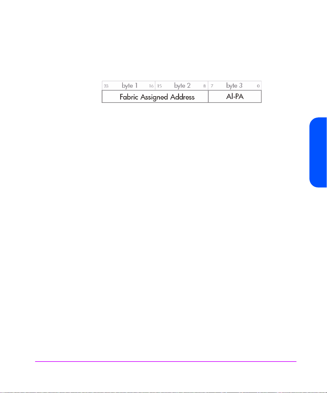
Addresses
Each Fibre Channel port also has a Port Address which is assigned during
loop initialization and/or Fabric Login. This is a 24-bit value in the following
format:
The AL_PA is the Arbitrated Loop Physical Address. This is normally assigned
dynamically during loop initialization.
If the loop is not attached to a fabric (in other words, when it is private,) the top
two bytes will be zero. If the loop is attached to a fabric, the tape drive is
assigned the top two bytes when it logs into the fabric.
Together, the three bytes pr o vi de a unique addres s on the F ibr e Channel f abr ic
that is used for frame addressing. It forms the equivalent of the Target ID or
Initiator ID in SCSI.
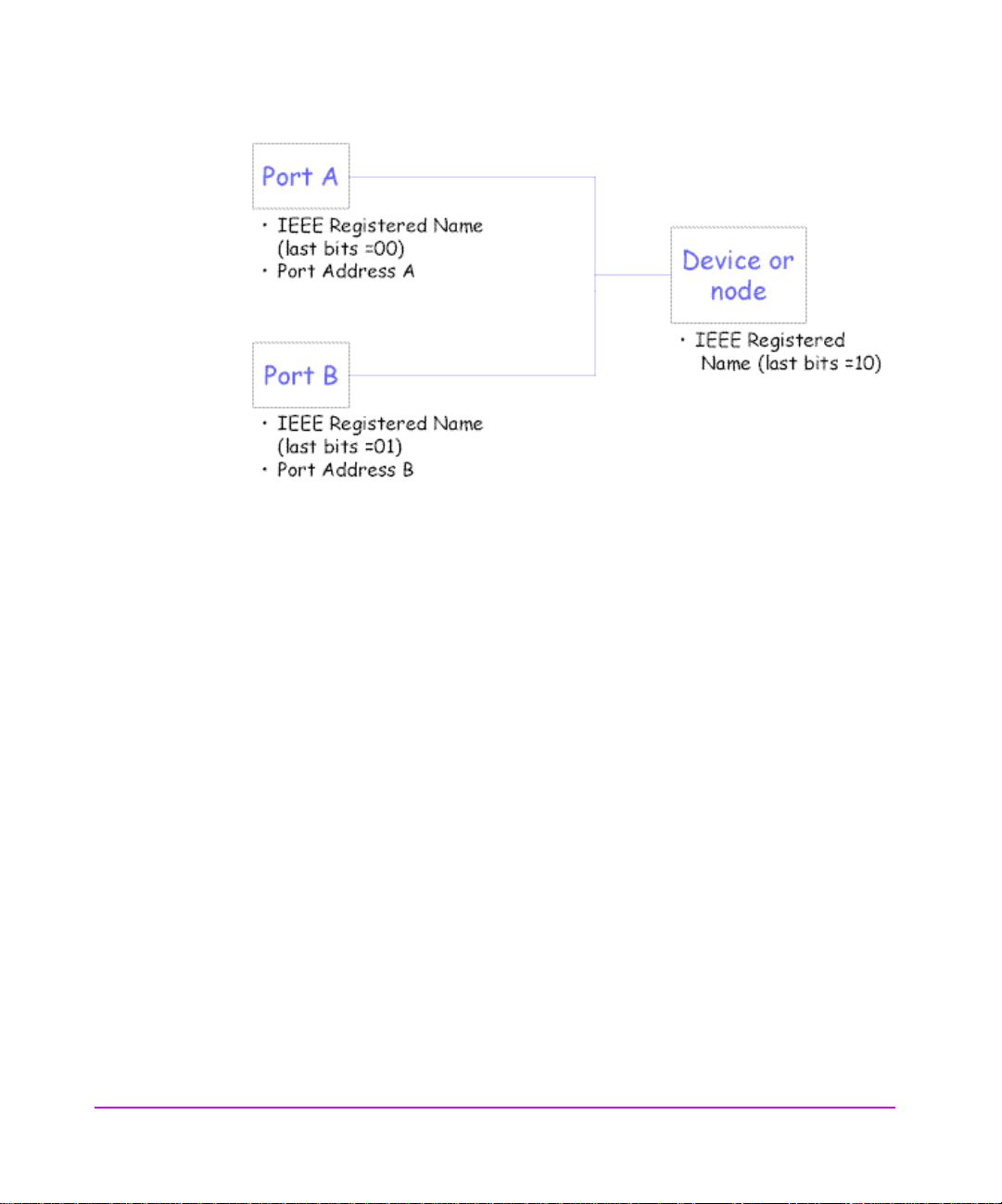
HP’s Implementation of Names and Addresses
The HP implementation uses three adjacent IEEE Registered Names:
■ The first (last bits = 00) is used as the Port A World Wide Name.
■ The second (last bits = 01) is used as the Port B World Wide Name.
Interface Implementation
■ The third name (last bits = 10) is used for the Device World Wide Name.
(These are assigned during manufacture from HP’s pool of names, although
only the first will actually be stored in the drive NV-RAM).
The port addresses will be assigned using the ‘standard’ AL_PA initialization
mechanisms. The ‘Fibre Channel Port Control mode page’ controls this. The
drive has the ability to support hard addresses as part of this scheme.
Interface Implem en ta tion 21
Page 22
The values of the names can be obtained using the Device Identification Vital
Product Information Page (part of the
INQUIRY command).
Implications for Libraries
■ Normally a standalone drive will operate using its own ‘hard’ names.
■ The drive kno ws it is in a library or other ‘managed’ environment since one
of the signal lines on the ACI (Automation Control Interface) will be tied
down.
In this case, the dr iv e wi ll not go on the FC loop until it is t old to . The libr ary
can optionally download a new, soft base name (Port A/Device Name)
into the drive at this point. The drive will then use this as the origin of its
names. The library manufacturer would be responsible for obtaining this
IEEE Registered Name. It would be a property of the library, not the drive.
■ If the library wants to ‘warm swap’ drives, it can. It just ‘turns off’ the drive
with the soft name using the ACI and then turns on the spare drive,
downloading the same name to it.
■ If a drive is r emo ved f rom th e library, it will not have the ACI signal tied low
and so will re v ert to its or iginal h ard name . It should f or get the s oft name in
this case.
■ If the library controller breaks, the drive will time out the ACI interface in
~10 seconds. The drive still knows it is in a library since the ACI signal is
22 Interface Implementation
Page 23

still tied low, so in this case it will use the soft name last downloaded. This
will allow drive access without confusing the host.
Field Replaceable Units
An FRU code identifies which part of the hardware is considered to have
failed. These codes turn up in sense data byte 14 and as the sense code
qualifier for sense codes 4400h (internal target failure) and 40XX (diagnostic
failure).
Althoug h the r e are no actual Field Replaceable Units on HP Ultrium dri ves, the
following sub-assemblies can be replaced at Repair Centres:
■ Drive PCA ■ Head Assembly
■ Mechanism ■ Front Panel
Descriptions of Signals (Parallel SCSI only)
The SCSI interface consists of 2 7 signals—9 contr ol lines, 16 data lines and 2
parity lines. A description of these signals is given in the following table.
Interface Implementation
Signal Name Driven by Description
-BSY
-SEL
-C/D
-I/O
Busy — OR-tied signal used to indicate that the SCSI bus is in use.
Select Initiator
Target
Control/Data Target Indicates whether control or data information is on the data
Input/Output Target Controls the direction of data movement on the bus with
Used to select a target during the Selection phase.
Used to select an initiator during the Reselection phase.
bus.
True (low) Control information
False (high) Data information
respect to the Initiator. This signal is also used to distinguish
between Selection and Reselection phases.
Interface Implementation 23
Page 24

Signal Name Driven by Description
True (low) Input to the initiator
False (high) Output from the initiator
-MSG
Message Target Indicates a Message phase on the bus.
True (low) Message phase
False (high) Command, Data or Status phases
-REQ
-ACK
Request Target Indicates a request for a REQ/ACK data transfer handshake.
Acknowledge Initiator Indicates an acknowledgment for a REQ/ACK data transfer
handshake.
-ATN
Attention Initiator Indicates that the initiator has a message to send to the
target.
-RST
Reset — OR-tied signal that is used to indicate a Reset condition.
DB(15-0) Data Bus — 16 data-bit signals that, with the parity-bit signal, form the
data bus. DB15 is the most significant bit , and has the highest
priority during the Arbitration phase.
DB(P1-P0) Data Bus — Data parity bits that ar e s et t o odd, but are jumper-selectable
options. There are two discrete parity bits, one for the lower 8
data bits, the other for the upper 8 bits. Parity is not valid
during the Arbitration phase.
24 Interface Implementation
Page 25

Messages
2
This chapter includes all SCSI messages, both supported and unsupported.
Parts of this chapter come from Section 5, Logical Characteristics, of the SCSI
standards (see page 13).
The message system provides an initiator and a target on the SCSI bus with a
means of managing communication. The available messages are listed in this
chapter.
Message Out Support (Parallel SCSI only)
Name Code Support
Abort 06h An abort condition is generated (see “Abort Handling” on page 16).
Bus Device Reset 0Ch A reset condition is generated (see “Reset Strategy” on page 15).
Extended Message 01h See “Extended Message Support” below.
Identify 80h+ The Identify Out message is sent by the initiator to identify the Logical Unit
to be accessed and to set Disconnect Privilege.
Initiator Detected
Error
05h The initiator has detected an error in the data being sent in a Command,
Data or Status phase. The drive will send a restore data pointers message
to retry the data transfer. (See “Message In Support (Parallel SCSI only)”
below for details).
If the message is received immediately after an Identify message or after
the Command Complete message has been sent, the drive will go Bus
Free.
Messages 25
Page 26

Name Code Support
Message Parity
Error
Message Reject 07h This message is sent when the initiator does not support a message sent b y
No Operation 08h This message has no effect and is ignored.
09h The initiator has detected a parity error in a message. The drive will retry
the message. (See ““Message In Support (Parallel SCSI only)” below for
details).
If the message is received immediately after an Identify message or after
the Command Complete message has been sent, the drive will go Bus
Free.
the drive or that the message is inappropriate. If the message being
rejected is Disconnect, Synchronous Data Transfer Request or Wide Data
Transfer Request, the operation continues without those features. For all
other messages, the message is treated as an Abort message.
If the message is received during a Command, Data or Status phase,
immediately after an Identify message or after the Command Complete
message has been sent, the drive will go Bus Free.
Message In Support (Parallel SCSI only)
Name Code Support
Command Complete 00h This message is sent by the drive at the end of the status phase to
indicate that a command is complete. Once the message is sent, the
drive releases the bus and goes to Bus Free.
Disconnect 04h This message is sent by the driv e to indicate that it is about to disconnect
from the bus and go to Bus Free. During a Data phase, it is always preceded by a Save Data P o inter s message. If a Message Rej ect message is
received in response to this message, then the disconnect is prevented.
Extended Message 01h See “Extended Message Support” below.
Identify 8Xh The Identify In message is sent to the initiator during reconnect to
indicate which Logical Unit is reconnecting.
26 Messages
Page 27

Name Code Support
Ignore Wide
Residue
23h This message is sent by the drive to the host to indicate that a byte on a
wide bus is not valid.
This is supported whenever a wide transfer is acti ve. It should be sent at
the end of the data phase. The standard action of the drive is to send
this message between the data phase and the status phase with no
disconnect.
Message Reject 07h This message is sent to the initiator when the message received by the
drive is unsupported or inappropriate.
Restore Pointers 03h This message causes the initiator to reset its data transfer pointers to the
values they held when the last save data pointers message was sent. It
will be sent when a parity error is detected on the bus or when an
Initiator Detected Error message is received in order to retry the data
phase.
Save Data Pointers 02h This message instructs the initiator to save its current data transfer
pointers for use with a subsequent Restore pointers message. This
message will always be sent before a Disconnect message during data
phases.
Extended Message Support
Name Code Support
Messages
Synchronous Data
Transfer Request
01h The drive will never initiate a Synchronous data transfer negotiation, but
will expect the initiator to do so.
If the message is received after selection and befor e the command phase,
it will then go to message-in phase and respond with a valid r esponse to
complete the negotiation.
Wide Data Transfer 03h The drive will never initiate a Wide data transfer negotiation but will
expect the initiator to do so.
If the message is received after selection and befor e the command phase,
it will then go to message-in phase and respond with a valid r esponse to
complete the negotiation.
Note that SDTR negotiated parameter s will become asynchr onou s after a
WDTR.
Messages 27
Page 28

Name Code Support
Parallel Protocol
Request
04h The drive will never initiate a Parallel Protocol Request transfer
negotiation but will expect the initiator to do so.
If the message is received after selection and befor e the command phase,
it will then go to message-in phase and respond with a valid r esponse to
complete the negotiation.
Synchronous Data Transfer Request
7 6 5 4 3 2 1 0
0
1
2
3
4
Extended Message (01h)
Extended Message Length (03h)
SDTR (01h)
Transfer Period Factor
Req/Ack Offset
Wide Data Transfer Request
7 6 5 4 3 2 1 0
0
1
2
3
Extended Message (01h)
Extended Message Length (02h)
WDTR (01h)
Transfer Width Exponent
28 Messages
Parallel Protocol Request
7 6 5 4 3 2 1 0
0
1
2
3
4
Extended Message (01h)
Extended Message Length (06h)
Parallel Protocol Request (04h)
Transfer Period Factor
Reserved (0)
Page 29

7 6 5 4 3 2 1 0
5
6
7
Reserved (0) QAS_Req DT_Req IU_Req
Req/Ack Offset
Transfer Width Exponent
Fields:
Transfer Period
Factor
09h Transfer period of 12.5s (FAST-80). Only valid when DT transfers have been
requested
0Ch Transfer period of 50s (FAST-20) — LVD/SE drives only
19h Transfer period of 100s (FAST-10)
32h Transfer period of 200s (FAST-5)
Req/Ack Offset This has a maximum value of 255.
Transfer Width
Exponent
For ST transfers, this can be either 0 (Narrow) or 1 (Wide).
For DT transfers, it must be set to 1.
QAS_Req 0 This bit will be ignored and the drive will always return zero.
DT_Req This bit determines whether DT mode has been requested, in other words, packetized
data transfers.
IU-Req 0 This bit will be ignored and the drive will always return zero.
Status
A Status byte is sent from the drive to the host during the Status phase at the
end of each command as specified in the SCSI specification, unless the
command has been cleared by an
message, or by a hard reset.
ABORT message, by a BUS DEVICE RESET
Messages
The Status bytes that the drive returns are as follows:
00h GOOD: This status indicates that the drive has successfully completed the command.
02h CHECK CONDITION: Any er r o r, exception, or abnor mal condition that causes sense data
to be set returns
CHECK CONDITION. The REQUEST SENSE command should be sent
following this status to determine the nature of the error.
04h CONDITION MET: This status will never be returned by an HP Ultrium tape drive.
Messages 29
Page 30

08h BUSY: The drive is unable to execute the command at this time. Try again later. The drive
tries to avoid using this status code during normal operation. It can sometimes be used
after commands have been aborted, during power-on and if there are multiple selecting
initiators.
10h INTERMEDIATE: This status will never be returned by an HP Ultrium tape drive.
14h INTERMEDIATE CND: This status will never be returned by an HP Ultrium tape drive.
18h RESERVATION CONFLICT: Returned if the drive is reserved by another party. See the
Reservation check.
22h COMAND TERMINATED: This status will never be returned by an HP Ultrium tape drive.
28h QUEUE FULL: This status can be returned by an HP Ultrium FC drive but will never be
returned by a SCSI tape drive.
30 Messages
Page 31

Commands—Introduction
This chapter contains general notes relating to the SCSI commands listed in
Chapter 4.
Summary
The following table is a summary of the SCSI commands for sequential access
devices, showing the operation code:
3
Opcode
(hex)
00
01
03
05
08
0A
10
11
12
13
15
16
17
19
1A
1B
1C
1D
Command Name
TEST UNIT READY
REWIND
REQUEST SENSE
READ BLOCK LIMITS
READ
WRITE
WRITE FILEMARKS
SPACE
INQUIRY
VERIFY
MODE SELECT
RESERVE UNIT
RELEASE UNIT
ERASE
MODE SENSE
LOAD/UNLOAD
RECEIVE DIAG RESULTS
SEND DIAGNOSTIC
Opcode
(hex)
1E
2B
34
3B
3C
44
4C
4D
55
56
57
5A
8C
8D
A0
Command Name
PREVENT MEDIUM REMOVAL
LOCATE
READ POSITION
WRITE BUFFER
READ BUFFER
REPORT DENSITY SUPPORT
LOG SELECT
LOG SENSE
MODE SELECT (10)
RESERVE UNIT (10)
RELEASE UNIT (10)
MODE SENSE (10)
READ ATTRIBUTE
WRITE ATTRIBUTE
REPORT LUNS
Commands—Introduction 31
Page 32

Command Details
The command descriptions in this section are listed in alphabetical order of
command name. Each command is described briefly. This is followed by a list
of pre-execution checks which are described below. The Command Descriptor
Block (CDB) is then given, with details of the various parameter bits and fields.
Pre-Execution Checks
Note In compliance with the SCSI specification, the drive terminates a
command with a
key to
is received which is not zero.
Before executing a command, the drive makes a number of checks. They fall
into three categories:
■ Checks on the command sent by the host. T hese ensure that no rese rved or
fixed fields have been set to illegal values. They check the syntax of
commands, in other words the cross dependency of fields. F or ex ample, the
Flag bit must not be set if the Link bit is not set.
■ Checks to ensure that there are no outstanding UNIT ATTENTION or
DEFERRED ERROR events posted for the host that has sent the command.
CHECK CONDITION status and sets the sense
ILLEGAL REQUEST when a reserved bit, byte, field or code
■ Checks on media access abilities. These are performed for commands
The checks are described below in alphabetical order. The usual order of
execution is Illegal Field, Fixed Bit, Flag Link, Bad LUN, Reservation, Deferred
Error, Unit Attention, Media Access, Media W r ite , Diagnosti c Statu s, Humidity ,
Parameter List.
Bad LUN Check
For all commands except INQUIRY 12h, this checks that the LUN specified by
the host is zero. The LUN is taken from the lowest 5 bits of the host’s
message.
32 Commands—Introduction
requiring access to the cartridge. A command is rejected if it attempts to
access the cartridge when no cartridge is present or the cartridge is
unloaded.
IDENTIFY
Page 33

■ If no IDENTIFY message is supplied, the LUN is taken from the host’s
■ If an IDENTIFY message is supplied, the LUN in the host’s Command
■ If the LUN is unsupported, and the host command is not REQUEST SENSE,
■ If the LUN is unsupported, and the host command is REQUEST SENSE, the
Deferred Error Check
A deferred error is generated when a command with immediate report fails
after the report has been returned. The check looks to see if a deferred error
exists f or the host whic h sent the command, in othe r words , a deferr ed err or fo r
which
exists, then the drive reports
command is set to
previous command failed).
Note that if a
both exist for an initiator, the
This is because the operation leading to the deferred error must have been
older than that leading to the unit attention. The drive reports the conditions in
the order in which they arose.
Command Descriptor Block.
Descriptor Block is ignored
CHECK CONDITION is reported to the host with a sense key of ILLEGAL
REQUEST
original sense data is replaced with a sense key of
, and additional sense of 2500h (logical unit not supported).
ILLEGAL REQ UEST, and
additional sense of 2500h (logical unit not supported). This new sense
data is returned to the host. Once the command has completed
successfully, the sense data is cleared.
CHECK CONDITION status has not yet b een reported. If such an error
CHECK CONDITION. The sense data for the
DEFERRED ERROR (which was generated when some
UNIT ATTENTION condition and a DEFERRED ERROR condition
DEFERRED ERROR condition will be reported first.
Diagnostic Status Check
This ensures that the drive is in a fit state to access the media. It does this by
checking that there is no
If the drive has failed diagnostics,
key of
on component X).
Commands—Introduction
DIAGNOSTI C FAIL status within the drive.
CHECK CONDI TION i s r e port ed w ith a se nse
HARDWARE ERROR and additional sense of 400Xh (diagnostic failure
Commands—Introduction 33
Page 34

Fixed Bit Check
For the READ, VERIFY and WRITE commands, a Fixed bit set to 1 indicates that
the length parameter of the command is for fixed block mode. If fixed block
mode is selected then the block size in the Mode Select block descriptor must
not be zero. Otherwise
set as described for the
Flag Link Check
This check ensur es tha t the host ha s not se t the F lag b it in the contr ol b yte o f the
command without setting the Link bit as well. If the test fails then
CONDITION
sense of 2400h (invalid field in CDB). The Flag field is identified as the bad
field.
Illegal Command Check
If the drive does not recognize the opcode of the command that it has been
sent, it will do one of the following:
■ Report CHECK CONDITION status. The sense key will be set to ILLEGAL
REQUEST
command opcode).
■ Report an invali d f i eld in the command descriptor block. The sense key will
be set to
(invalid field in CDB) and the field pointer in the sense data will be zero.
CHECK CONDITION is reported and the sense data is
ILLEGAL FIELD check.
CHECK
is reported with a sense key of ILLEGAL REQUEST and additional
and the additional sense code will be set to 2000h (invalid
ILLEGAL REQUEST, the additional sense code will be set to 2400h
Illegal Field/Request Check
Checks are performed to ensure the host has not set any of the following in the
command descriptor block:
■ a fixed field
■ a reserved field
■ the control field
■ two or more fields to logically conflicting values
If a field has been set to an illegal value:
■ CHECK CONDITION status is reported to the host with a sense key of
ILLEGAL REQUEST and additional sense of 2400h “invalid field in CDB”.
34 Commands—Introduction
Page 35

■ The sense key specific bit is set and the sense key specific bytes will be a
■ The command/data bit is set, indicating that the illegal parameter was in
Note Command descriptor blocks ar e scanned from left (bit 7) to right
Media Access Check
This checks if the drive is able to perform media access commands. If the
media is inaccessible then
key of
associated with the
field pointer.
the command.
(bit 0), and down (from byte 0 to byte n). The field pointer will
be set to point to the first bit of the first illegal field encountered
using this scanning route. In some cases, where multiple fixed
fields are conti guous, th e fi eld pointer mi ght be set to poin t to the
first bit o f the first fixed fi el d in the group of fixed fie lds , w he reas
the actual illegality may lie in a later bit.
CHECK CONDITION status is reported with a sense
NOT READY. The additional sense will be set to one of the codes
NOT READY key.
Commands—Introduction 35
Commands—Introduction
Page 36

Media Information Check
Durin g po w er-on and fol lo w in g a S CS I r e set , kno w ledg e o f the w he r eabo ut s of
the cartridge is unavailable. It is not possible to execute commands which
assume that this knowledge is available until the drive has recovered from the
power-on or reset.
The test checks whether the drive knows if a cartridge is physically present in
the drive.
If information about the tape cartridge is not available, the test fails with
CHECK CO NDIT ION, a sens e ke y o f NOT READ Y, and additional sense of 3E00
(logical unit has not self-configured yet).
36 Commands—Introduction
Page 37

Media Write Check
This checks whether the media is write-pr otected . If it is, CHE CK CONDI TION is
reported with a sense key of
(write-protected).
Parameter List Check
For LOG SELECT, MODE SELECT and some diagnostic commands, the
associated data sent to the drive is in the form of parameter lists. These are
described under the command names in the next chapter. Checks are
performed to test the following:
■ Fixed and reserved fields have not been modified. Fixed fields are
■ A field has been set to an invalid value.
■ The syntax of the page of parameters has been violated—for example,
DATA PROTECT and additional sense of 2700h
indicated by a number in round brackets following the field name.
wher e a p art ic ul ar v alu e in on e f i el d i mpo s es li mit ati ons o n t he v a li d range
for another field.
Reser vation Check
If a field has been set to an illegal value,
host with a sense key of
(invalid field in parameter list).
The drive scans the data in the Command Description Block from “left” (bit 7)
to “right”, and “down” (from byte 0 to byte n). It sets the field pointers to the
first bit of the first bad field encountered. If the bad field is contained in a
contiguous group of fixed fields, the pointers indicate the first bit of the first
field in the group, even though the error may be in a later field in the group.
Note With
parameter list before acting on an y par amete r s, so all the mode
parameters need to be correct before any of them are
implemented.
This chec ks t o see if t he dr i ve h as been reserved for u se b y a h ost , an d if it h as,
whether the host is the same host that sent the command being executed.
If the drive has been reserved for some other host then
status is reported.
See the
RESERVE UNIT (page 141) and RELEASE UNIT (page 121) commands.
ILLEGAL REQUEST and additional sense of 2600h
Mode Select, the drive checks the integrity of the whole
CHECK CONDITION is reported to the
RESERVAT IO N C ONFLIC T
Commands—Introduction
Commands—Introduction 37
Page 38

Unit Attention Check
This checks if a UNIT ATTENTION condition exists for the host which sent the
command. If it does, the drive reports
key of
UNIT ATTENTION. The remaining sense data will be set according to the
unit attention condition which exists. See Unit Attention Sense in the
description of the
REQUEST SENSE command on page 132.
Command Descriptor Block
A SCSI command descriptor block (CDB) is a sequence of 6, 10, 12 or 16
bytes sent by a host to a SCSI target with the bus in command phase. The CDB
tells the drive what action should be perfor med . The f inal byt e is know n as the
Control byte.
7 6 5 4 3 2 1 0
0 Group Code Operation Code
1 Reserved (0)
CHECK CONDITION status with a sense
2 (MSB)
n
-1 (LSB)
n Vendor Unique (0)
There are a number of fields in a CDB which are common to all commands.
These are shown in the following table.
Group Code
Operation Code
and
The operation code uniquely identifies the command. The top three bits of the
operation code are known as the group code and these define the length of the
command descriptor block:
Group 0
Group 1
Group 2
Group 3
Group 4
Group 5
Group 6
Group 7
38 Commands—Introduction
Six-byte commands
Ten-byte commands
Ten-byte commands
Six-byte commands
Sixteen-byte commands
Twelve-byte commands
not supported
not supported
Multi-Byte Parameter
Reserved (0)
NACA(0) Flag (0) Link (0)
Page 39

Reserved A reserved field should always be set to zero. The drive checks reserved fields, and if one is
Multi-Byte
Parameter
non-zero then it will reject the command with
A multi-byte parameter field in a co mm and is “big-endian”, that is, bit 7 of the first byte of this
field is the most significant.
CHECK CONDITION.
Control The control field i s mainly c oncerne d with the u se of link ed comm ands. Thes e are not support ed
by the LTO SCSI Command Set, so a CHECK CONDITION will be generated if this field is set to
anything other than zero.
Vendor-Unique This field is ignored by the firmware
NACA 0 The Normal ACA flag is 0, indicating that it is not supported.
Flag 0
Link 0 Linked commands are not supported.
Commands—Introduction 39
Commands—Introduction
Page 40

40 Commands—Introduction
Page 41

Commands
4
This chapter describes all SCSI commands. Parts of the chapter are based on
sections of the SCSI specification (see page 13).
For general notes on the command descriptions, see Chapter 3.
Commands 41
Page 42

ERASE 19h
The ERASE command is used to erase data on tape from the current logical
position. The Long bit is used to decide whether the ‘old’ data is physically
overwritten or not.
Pre-Execution Checks:
Illegal Field Reservation Deferred Error Unit Attention
Media Access Media Write Diagnostic Status
Command Descriptor Block:
7 6 5 4 3 2 1 0
0
1
2
3
4
5
Operation Code (19h)
Reserved (0) Immed Long
Reserved (0)
Reserved (0)
Reserved (0)
Control
CDB Fields:
Immed 0 The drive reports st atus after the command h as completed.
1 The drive reports status when it starts the command (after any pre-
execution checks and prerequisite unloads have completed).
Long The Long bit controls the distance to be erased.
0 The current position becomes the end of logical data.
1 End of Data is written, followed b y Data Set Separators to the end of the
tape.
Note The only use for short erase is to truncate data at current logical
position. It cannot be used to create a “hole” in the tape into
which data can subsequently be written “in place”. This will
merely cause the drive to streamfail. The logical tape position is
unaffected by this command. A
CHECK CONDITION for Early
42 Commands
Page 43

Warning EOM (drive error code 2C98h) will only be given if the
tape was logically positioned past EOT immediately prior to this
command.
Erase Specific Status:
Event Status Key Additional Sense
The erase fail s CHECK CONDITION HARDWARE ERROR 5100h (era se failure)
Commands
Commands 43
Page 44

INQUIRY 12h
INQUIRY tells the drive to return information about the basic operating
parameters to the host . These par ameters cannot be changed. T he driv e re turns
Inquiry data to the host in a data-in phase.
Note This command is immune from most of the pre-execution checks
that other commands must pass (for ex am ple , it can be execut ed
while the unit is reserved for another host). U
deferred error conditions are preserved and reported on
subsequent commands.
Pre-Execution Checks:
Only the Illegal Field Check is performed before the command is executed.
nit attention and
If the EVP D bit is clear, the page code must b e zero, otherwis e
reported.
If the EVPD b i t i s s e t, the page code must be on e o f t h e su p po r te d p a ge cod e s
for Inquiry data. Otherwise
Command Descriptor Block:
7 6 5 4 3 2 1 0
0
1
2
3
4
5
LUN Reserved (0) EVPD
CDB Fields:
LUN This field is ignored.
EVPD Enable Vital Product Data
01Normal inquiry data is returned.
A page of vital product data is returned.
illegal request is
illegal request is reported.
Operation Code (12h)
Page Code
Reserved (0)
Allocation Length
Control
44 Commands
Page 45

Page Code If the EVPD bit is zero the Page Code field must be zero.
If the EVPD bit is set to 1, the drive returns the Inquiry page in this Page Code field:
00h
Supported Vital Product Pages page
80h
Unit Serial Number page
83h
Device Identification page
C0h
Firmware Revision Levels page
C1h
Hardware Revision Levels page
C2h
PCA Revision Level s page
C3h
Mechanism Revision Levels page
C4h
Head Assembly Revision Levels page
C5h
ACI page
C6h
ARM Firmware Revision Levels page
C7h
HI Glue Logic Levels page—Fibre Channel only
Allocation
Length
The maximum amount of data (in bytes) that should be returned. If more than this is available,
the amount returned is truncated to allocation length. No error is reported.
INQUIRY Data Pages
Returned Data:
INQUIRY returns its standard data if the EVPD bit is zero, or returns a page of
data as specified by the Page Code field when EVPD is one.
Commands
Standard Inquiry Data Format (LUN0)
This is the data returned by the drive in response to an Inquiry command with
its EVPD bit set to zero . The data also depends on the value of the LUN field in
the Inquiry CDB, the LUN value in the identify message and the configuration
of the drive.
Note that the data below is for the standard distribution firmware.
7 6 5 4 3 2 1 0
0
Peripheral Qualifier (000b) Peripheral Device Type (01h)
1
RMB (1) Reserved (0)
2
3
AERC (0) Obsolete NACA(0) HiSup(0) Response Data Format (2)
4
Version Number (3)
Additional L e n gt h (5Bh)
Commands 45
Page 46

7 6 5 4 3 2 1 0
5
6
BQue(0) EncSvr(0) VS(0) MultiP MChngr Obsolete Obsolete Adr16
7
RelAdr(0) Obsolete WBus16 Sync Linked(0) TranDis(0) CmdQue(0) VS(0)
8
(MSB)
15
16
(MSB)
31
32
(MSB)
35
36
(MSB)
55
56
57
58
59
72
73
74
95
(MSB)
(MSB)
(MSB)
Reserved (0) Clocking QAS (0) IUS (0)
Reserved (0)
Vendor Identification
(“HP “)
Product Identification
Product Revision Level
Reserved (0)
Reserved (0)
Version Descriptor 1
- - - - - - - -
Version Descriptor 8
Reserved (0)
(LSB)
(LSB)
(LSB)
(LSB)
(LSB)
(LSB)
(LSB)
46 Commands
The Standard Inquiry Data is based on the SCSI 3 standard for Standard
Inquiry Data.
For the LUN to which the drive is attached, the Peripheral Qualifier field is set
to 000b, the P er ipher al Dev i ce Type field is set to 01h, the Remova ble Medium
(RMB) flag is set to 1 and the Device-type modifier is set to 0.
Page 47

Inquiry Data Fields
Peripheral Qua lifier 000b
There is a device on the logical unit selected, so the LUN field in the identify
message was 0.
011b
The LUN field in the identify message has specified an unsupported logical unit.
This means any LUN other than 0.
Peripheral Dev i ce
Type
01h
Sequential Access Device
08h
Medium Changer Device
1Fh
No Device (the Peripheral Qual ifier will be 011b in this case)
RMB 1 The Removable Medium bit is one, indicating that the tape can be removed.
Device-Type Modifier 0 This is a six-bit user defined code, set to zero.
Version Number 3 The Version Number is always set to 3, indicating that the drive complies to
ANSI X3.301:1997
AERC 0 This field is zero, indicating that Asynchronous Event Reporting Capability is not
supported.
NACA 0 The Normal ACA flag is 0, indicating that it is not supported.
HiSup 0 The Hierarchical Support flag is 0, indicating that the hierarchical addressing
model is not supported.
Response Data
Format
2 This field has the value 2, indica ting that the Inq uiry Data format compl ies with the
ANSI version of SCSI-2.
Additional Length The length in bytes of the length of the rest of the Inquiry data.
5Bh There are 91 (5Bh) more bytes of Inquiry data.
BQue Basic Queuing flag
0 The flag is zero for SCSI drives. Together with the CmdQue flag being zero this
indicates that the device does not support tagged tasks for this logical unit.
1 The flag is 1 for Fibre Channel drive, indicating the basic queuing is supported.
Commands
EncSvr The Enclosure Services flag is zero to indicate that the tape drive does not support
Enclosure Services command.
MultiP 0 The drive has a single port and does not implement multi-port requirements.
1 The drives has multiple ports.
MChngr The Medium Changer bit:
01The drive is not embedded within or attached to a medium transport element.
The drive is embedded wit h in or att ac hed to a medium transport elem en t .
Adr16 The 16-Bit Address flag is set according to whether the hardware supports this bus
feature. The flag is only valid for parallel SCSI and is clear for all other low level
interfaces.
RelAdr 0 Relative Addressing is not supported.
Commands 47
Page 48

WBus16 The Wide Bus 16 flag is set according to whether the hardware supports this bus feature.
The flag is only valid for parallel SCSI and is clear for all oth e r low level interfaces.
Sync 0 Synchronous data transfer is not supported. The flag should be zero for all low-
level interfaces apart from parallel SCSI.
1 Synchronous data transfer is supported. The flag is only valid for parallel SCSI.
Linked 0 The device does not support linked commands.
CmdQue 0 The CmdQue flag is always zero. If the Basic Queuing (BQue) flag is also zero, this
indicates that the device does not support tagged tasks for this logical unit.
Vendor
Identification
Product Iden tification A left-justified, vendor-specific, 16-byte string field of ASCII characters with space
Product Revision Level A vendor-specific string of four ASCII characters: “CYMV”:
Clocking 0For FC drives.
A vendor-specific, 8-byte string of ASCII characters, left justified and padded with space
characters “HP”.
character padding on the right. The string consists of two parts:
■ First half (bytes 16–23): “Ultrium”
■ Second half (bytes 24–31): “<generation>-<interface type>”
■ The following strings have been defined:
■ Generation 2 FC drive: “Ultrium 2-SCSI” (“SCSI” is not a typo!)
■ Generation 2 SCSI drive: “Ultrium 2-SCSI”
■ C is the codename (F for a full-height drive)
■ Y is the year code . “0” is 2000, “1” is 2001, up to “9” for 2009. Alpha character s are
then used if needed.
■ M is the month code. “1” is January up to “B” for December.
■ V is an ASCII character representing the OEM variant of the code. “D” is the standard
distribution variant.
3 For SCSI drives, indicating that the drive supports both ST and DT transfers.
48 Commands
Page 49

Version Descriptor These fields can be used to identif y up to eight stand ards t o whi ch the d riv e con form s. The
values supported are listed below.
For SCSI drives, it is recommended that the first version descriptor is used for the SCSI
architecture standard, followed by the physical standard, if any, followed by the SCSI
protocol, followed by the appropriate SPC versio n , fo ll owe d by the device type command
set, followed by the secondary command set, if any.
The following are the SCSI version descriptors:
Value Standard
1
0054h
2
0B1Ch
3
0227h
4
021Ch
5–8
The following are the FC version descriptors:
0000h
Value Standard
1
0054h
2
0917h
3
0D7Ch
4
0DA0h
5
131Bh
6
1320h
7
0277h
8
021Ch
SAM-2 T10/1157-D rev 23
SPI-3 ANSI NCITS.336:2000
SPC-2 ANSI NCITS.351:2001
SSC ANSI NCITS.335:2000
not used
SAM-2 T10/1157-D rev 23
FCP-2 ANSI NCITS.332:1999
FC-AL-2 ANSI NCITS.350:200x
FC-FS (no version claimed)
FC-Tape T11/1315 revision 1.17
FC-FLA (no version claimed)
SPC-2 ANSI NCITS.351:2001
SSC ANSI NCITS.335:2000
Commands
Vendor Specific data may be sent after the Product Revision Level.
Vital Product Data Pages
The following tables describe the vital product data pages. These pages are
returned by the
appropriate Page Code is set in the Command Descriptor Block. They contain
vendor-specific produ ct information.
Supported Vital Product Data Pages Page
This is the data returned by the drive in response to an Inquiry command with
its EVPD bit set to one and its Page Code field set to 0.
INQUIRY command when the EVPD bit is set and the
Commands 49
Page 50

This page contains a list of all the VPD page-codes supported by the drive.
7 6 5 4 3 2 1 0
0
1
2
3
4
5
6
7
8
9
10
11
12
13
14
Peripheral Qualifier (0) Peripheral Device Type (1)
Unit Serial Number Page
The Unit Serial Number Page contains a single value which is a 10-byte ASCII
string. The string, with the Vendor Identification and Product Identification
fields in the standard Inquiry data, uniquely identifies the drive.
Page Code (00h)
Reserved (0)
Page Length (0Ah for SCSI drives, 0Bh for FC drives)
Supported Pages Code (00h)
Unit Serial Number Page (80h)
Device Identification Page(83h)
Firmware Revision Levels Page (C0h)
Hardware Revision Leve ls Page (C1h)
PCA Revision Levels Page (C2h)
Mechanism Revision Levels Page (C 3h)
Head Assembly Revision Levels Page (C4h)
Auto-Changer Interface Revision Levels Page (C5h)
ARM Firmware Revision Levels page (C6h)
HI Glue Logic Levels page (C7h)—Fibre Channel only
50 Commands
13
7 6 5 4 3 2 1 0
0
1
2
3
4
Peripheral Qualifier (0) Peripheral Device Type (1)
Page Code (80h)
Reserved (0)
Page Length (0Ah)
(MSB)
Serial Number
(LSB)
Page 51

Device Identification Page
The Device Identification page contains information that identifies the tape
drive uniq uely. For SCSI, a combinati on of the Vendor ID and Serial Number is
Commands
returned. For Fibre Channel, the Port and Device Names are returned as well.
7 6 5 4 3 2 1 0
0
1
2
3
4
n
Peripheral Qualifier (0) Peripheral Device Type (1)
Page Code (83h)
Reserved (0)
Page Length (n
(MSB)
Identification Descriptors
-3)
(LSB)
Identification Descriptors are constructed as follows:
7 6 5 4 3 2 1 0
0
1
2
3
4
(MSB)
n
Reserved (0) Code Set
Reserved (0) Identifier Type
Reserved (0)
Identifier Length (n-3)
Identifier
(LSB)
Code Set 1 The Identification Descriptor is a binary field.
2 The Identification Descriptor contains only ASCII data.
Identifier Type 1 Vendor ID followed by th e produc t identification field f rom the s tandard in quiry data an d the
serial number field from the Serial Number Inquiry Page.
3 All devices with a Fibre Channel interface support an Identifier type of 3. In this case the
Identification Descriptor is the Fibre Channel 64-bit Name Identifier.
Defined Ide nti fiers
The following identifi ers will be returned in the given or der. What Port Name is
returned depends on which port the Inquiry is sent to.
Commands 51
Page 52

Device Serial Number (FC and SCSI)
7 6 5 4 3 2 1 0
11
12
27
28
37
11
0
1
2
3
4
(MSB)
(MSB)
(MSB)
Reserved (0) Code Set ( 2 )
Reserved (0) Identifier Type (1)
Reserved (0)
Identifier Length (34)
Vendor ID
(LSB)
Product Identification
(LSB)
Serial Number
(LSB)
Port Name (FC only)
7 6 5 4 3 2 1 0
0
1
2
3
4
(MSB)
Reserved (0) Code Set (1)
Reserved (0) Iden ti fier Type (3)
Reserved (0)
Identifier Length (8)
Port Name
(IEEE Registered Name)
(LSB)
52 Commands
11
Device Name (FC only)
7 6 5 4 3 2 1 0
0
1
2
3
4
(MSB)
Reserved (0) Code Set (1)
Reserved (0) Iden ti fier Type (3)
Reserved (0)
Identifier Length (8)
Device Nam e
(IEEE Registered Name)
(LSB)
Page 53

Port Identifier (FC only)
0
1
2
3
4
7
0
1
2
3
4
11
7 6 5 4 3 2 1 0
Reserved (0) Code Set (1)
Reserved (0) Identi fier Type (4)
Reserved (0)
Identifier Length (4)
(MSB)
Port Identifier
(LSB)
The Po rt Identifier will be set to 1 if the addressed port is port A, and set to 2 if
the addressed port is Port B.
SCSI Type 3 Identifier (SCSI only)
7 6 5 4 3 2 1 0
Reserved (0) Code Set (1)
Reserved (0) Iden ti fier Type (3)
Reserved (0)
Identifier Length (8)
(MSB)
SCSI Identifier
(IEEE Registered Name)
(LSB)
Commands
Driv e Component Revi sion Levels Pages
7 6 5 4 3 2 1 0
0
1
2
3
4
29
Peripheral Qualifier (0) Peripheral Device Type (1)
Page Length (5Ch)
(MSB)
Component (“CCCCCCCCCCCC”)
Page Code
Reserved (0)
(LSB)
Commands 53
Page 54

30
48
49
72
73
95
7 6 5 4 3 2 1 0
(MSB)
Version (“RRR.VVV”)
(LSB)
(MSB)
Date (“YYYY/MM/DD hh:mm”)
(LSB)
(MSB)
Variant (“XXXXXXXXXXXX”)
(LSB)
The Drive Component Revision Levels pages contain details of the revisions of
each of the major sub assemblies of the drive. For any given product, if these
pages are the same then the drive has been built with the same components
and with the same manufacturing process.
Each entry is a null-terminated ASCII string.
Page Code Page Code Component Name
C0h - Firmware
C1h - Hardware
C2h - PCA
C3h - Mechanism
C4h - Head Assembly
C5h - ACI
C6h - ARM
C7h - HI Glue Logic
Component A 12-character entry to identify the component that the revision is for.
Version A 7-character version code with a three- dig i t major revision number, a
period and a three-digit minor version num ber .
Date The date of the version.
Variant An identifier indicating what version of the product this is.
8000 0100h
8002 0100h
“HI Glue Logic” (FC only)
Generation 2 full-height SCSI
Generation 2 full-height FC
“Firmware”
“Hardware”
“PCA”
“Mechanism”
“Head Assy”
“ACI”
“IO Firmware”
54 Commands
Page 55

LOAD/UNLOAD 1Bh
The LOAD/UNLOAD command allows the host to specify that a tape cartridge
present in the drive is either made ready for data transfer (“loaded”) or
disabled for data transfer (if Prevent Media Removal is set). It can also cause
the cartridge to be ejected from the drive (“unloaded”).
Pre-Execution Checks:
Illegal Field Reservation Deferred Error
Unit Attention Diagnostic Status Media Information
If an unload is to be performed, the drive checks if the tape is currently being
loaded. If it is,
and additional sense of 0401h (becoming ready).
If a load is to be performed, the drive c hecks to ensur e that a ta pe cartri dge is
present. If not, it reports
and additional sense of 3A00h (medium not present). If the media is currently
being unloaded or ejected, it reports
NOT READY and additional sense of 0400h (cause not reportable).
Command Descriptor Block:
CHECK CONDIT ION is reported with a sense key of NOT READY
CHECK CONDITION with a sense key of NO T READY
CHECK CONDITION with sense key of
Commands
7 6 5 4 3 2 1 0
0
1
2
3
4
5
Reserved (0 ) Hold EOT (0) ReTen Load
Operation Code (1Bh)
Reserved (0) Immed
Reserved (0)
Reserved (0)
Control
CDB Fields:
Immed 0 The drive reports status afte r the command has completed.
1 The drive reports status when it starts the command (after any pre-execution checks
and prerequisite unloads have completed).
Commands 55
Page 56

Hold 0 A normal load/unload will be perfor med.
1 A load will cause the cartridge to be pull ed in and se ated in the d rive, but the t ape will
not be threaded.
An unload will cause the tape to be unthreaded, but the cartridge will not be ejected.
In Hold position, the Cartridge Memory is accessible.
ReTen This field is ignored.
Load 0 The drive perform s an unload operati o n.
1 The drive performs a load operation.
Load/Unload Specific Status:
Following a successful LOAD command, CHECK CO NDITION is posted to all
initiators other than the initiator of the
UNIT ATTENTION, with additional sense of 2800h (not ready to ready
transition). There is an exception to this: if a load occurs when the tape is
already loaded, no
UNIT A TTENTION is clear ed , unsoli cit ed positional sens e is set . The sen se
Once
key will be
NO SENSE with additional sense of 0004h (BOT detected).
If an unformatted tape is inserted, the drive loads it and it behaves as if it is a
blank tape.
If a cartridge with no Cartridge Memory or a failed Cartridge Memory is
loaded,
CHECK CONDITION is returned with a sense key of MEDIUM ERROR,
with additional sense of 5200h (cartridge fault).
UNIT ATTENTION sense is generated.
LOAD command. The sense key is set to
56 Commands
Loading a Cartridge
The drive loads a tape automatically when it is inserted, without any host
interaction. If the load is successful, media access commands are permissible
(see the Media Access check).
If the tape is already loaded when a Load request is received, the tape is
positioned at the beginning of the tape (as though a
Unlike a “full” load,
UNIT ATTENTION with additional sense of 2800h (not
ready to ready transition) is not generated for other hosts.
If the tape is in the process of being loaded when the Load request is receiv ed,
the drive will wait for the load to complete and, assuming the load was
successful, take one of the following actions:
■ If the Load was issued by the current host (that is, a previous immediate-
reported load) and completed successfully,
further action is taken.
REWIND had been sent).
GOOD status is reported. No
Page 57

■ If the Load was issued by some other host (or was an autoload) and
completed su ccessfull y ,
UNIT ATTENTION and additional sense of 2800h (not ready to ready
CHECK CONDI TION is r eported, wit h a sense key of
transition).
■ If the Load was issued by the curr ent host and failed , CHECK C ONDIT ION is
reported, since a deferred error condition will exist for the current host.
■ If the Load was issued by some other host and failed, the load will be re-
attempted on behalf of the current host.
Unloading a Cartridge
If an unload is requested and there is a tape present in the drive (either
loaded, loading or unloading):
1 Any buffered data is written to tape.
2 The tape is rewound to the physical BOM (beginning of media).
Commands
3 If medium removal is prevented,
sense key of
ILLEGAL REQUEST and additional sense of 5302h (medium
CHECK CONDITION is reported with a
removal prevented).
4 G
OOD status is reported if the tape unloaded successfully. Otherwise,
another unload operation is initiated on behalf of the host that issued the
unload request.
Following an unload, any media access commands will be rejected by the
Media Access check.
■ If an unload request is received while the tape is in the process of
unloading (for example, as a result of pressing the eject button), it will be
queued until the unload is complete.
■ If an unload request is received while there is no tape present, or if a tape
is present but not loaded and medium removal is prevented,
GOOD status
is reported.
It is possible to unload and eject the cartridge by pressing the Eject button on
the front panel.
Commands 57
Page 58

LOCATE 2Bh
The LOCATE command moves the current logical position to the position
specif i ed by the comm and . The n ew po siti on is sp ecif ie d by the off set fr om st art
of the media in terms of b l ocks . The first bloc k (that is, BOT) is block address 0.
Any unwritten data is written to tape before the command is executed.
Pre-Execution Checks:
Illegal Field Reservation Deferred Error
Unit Attention Media Access Diagnostic Status
Command Descriptor Block:
7 6 5 4 3 2 1 0
0
1
2
3
(MSB)
6
7
8
9
Reserved (0) BT (0) CP (0) Immed
Operation Code (2Bh)
Reserved (0)
Block Address
(LSB)
Reserved (0)
Partition (0)
Control
CDB Fields:
BT Block address Type. This field is not supported and sho uld always be set to zero indicating
that the Block Address field represents the count of all blocks and filemarks between the
beginning of the media and the current logical position.
CP Change Partition. This field is not supported and should be set to zero.
Immed 0 The drive only reports status after the Locate command has completed.
1 The drive reports status when it starts the comma nd and continue s with the positioning
in the background.
58 Commands
Page 59

Block
Address
The Block Address specifies the number of blocks and filemarks between BOM and the
position to be located.
Partition Not supported.
Locate Specific Status:
Event Status Key Additional Sense
EOD encountered CHECK CONDN BLANK CHECK 0005h (EOD encountered).
EOM encountered CHECK CONDN MEDIUM ERROR 00 02h (EOT encountered). EOM bit set.
Failed to read data—media
error or non-fatal drive
error
Early Warning EOM
encountered
Data format corrupt CHECK CONDN MEDIUM ERROR 3001h (can’t read media, unknown format)
CHECK CONDN HARDWARE ERROR 3B00h (sequential positioning error)
Early warning end of medium informa t ion is not reported for Locate commands
Commands
Commands 59
Page 60

LOG SELECT 4Ch
The Log Select command causes log data on the drive to be reset to its default
value or to be set to an initiator specific value.
Pre-Execution Checks:
Illegal Field Reservation Deferred Error Unit Attention
Command Descriptor Block:
7 6 5 4 3 2 1 0
0
1
2
3
6
7
8
9
PC Reserved (0)
(MSB)
Operation Code (4Ch)
Reser v ed (0) PCR SP (0 )
Reserved (0)
Parameter List Length
(LSB)
Control
CDB Fields:
The following are valid combinations of values for the PCR (Parameter Code
Reset), Parameter List Length and PC (Page Control) fields:
PCR P a r a m et er List Length PC Result
1 0 01b or 11b All the logs on the drive that can be rese t are reset
to their default values.
1 0 00b or 10b No action is taken and
0 >0 01b or 11b Data is sent from the host and is written to the
indicated logs, provided those logs are wr itabl e.
Otherwise
REQUEST
CHECK C ONDIT ION sta tus is r etu rned , the se nse k ey is set t o ILLEGAL
with additional sense of 2400h (Invalid Field in CDB).
GOOD status is returned.
PCR 0 Parameter Code Reset. The function performed is defined by the PC field.
60 Commands
Page 61

SP 0 The Save Page (SP) flag is not supported and must be set to 0.
PC The Page Control field defines the type of parameter values to be selected:
00b
No operation is performed. The Parameter List Length must be zero. If it is not, check
or
condition invalid field in CDB is set.
10b
01b The drive will clear logs as specified by the parameter data.
11b The drive will clear all of its internal logs.
Parameter
List Lengt h
0 No data is to be transferred. This is not considered an error.
>0 Specifies how many bytes of parameter data are to be sent. The data transferred will
consist of zero or more 4-byte log page he aders with the page length in those hea ders
set to zero. For each log page header received, the drive clears the associated log.
Commands
Commands 61
Page 62

LO G SENSE 4Dh
LOG SENSE allows the host to read the drive’s logs. A single log is returned
with each invocation of
Pre-Execution Checks:
Illegal Field Deferred Error Unit Attention
The P age Code must matc h one of the supported log page codes. If it does not ,
then
CHECK CONDI T ION st atus is r eported . Sense data will be as descr ibed in
the Illegal Field Checks.
Command Descriptor Block:
7 6 5 4 3 2 1 0
LOG SENSE.
0
1
2
3
6
7
8
9
PC Page Code
(MSB)
Operation Code (4Dh)
Reserved (0) PPC (0) SP (0)
Reserved (0)
Allocation Length
Control
CDB Fields:
PC The Page Control field defines the type of log parameter to be returned:
00b Current Threshold Values—any parameters in the log that are counters contain the
maximum value that they can count to.
01b Current Cumulative Values—any parameters in the log that are counters contain their
current counts.
Note: Counts are reset to their de fault cumulative val ues (see belo w) following a p ower-on,
reset or bus device reset. Media related counts are also reset following a load.
10b Default Threshold Values—same as the Current Threshold Values
(LSB)
62 Commands
Page 63

11b Default Cumulative Values—any parameters in the log that are counters contain the initial
values of those counters (set at power-on, reset, bus device reset and, in the case of media
logs, load).
The PC field has no effect on the data returned when the selected log contains event or trace codes
rather than counts.
Page Code The Page Code field identifies which log page is being requested by the host. See
the list of valid page codes.
Allocation
Length
The Allocation Length field specifies the maximum number of bytes of data that should be returned
to the host. The drive will return the entire log or Allocation Length bytes, whichever is the lesser.
Log Page Format
All log pages except Page 0 consist of a page code header followed by a
number of parameters. The page header has the following format:
7 6 5 4 3 2 1 0
Commands
page 64 for
0
1
2
(MSB)
3
Page Code
Reserved (0)
Page Length
(LSB)
The page code is a byte value that uniquely identif i es w hich Log Page is being
returned. The Page Length indicates the number of additional bytes in the
parameters.
For the
Log Select com mand onl y, the four bytes sh o wn a bov e ar e sen t f or eac h
log page to be cleared. The Page Length field should be set to zero.
For the
Log Sense command one or more parameters is sent. See the actual
page descriptions abo ve f or mor e inform ation. Not e that all the parameters f or
a particular page must be sent. Each parameter has the following format:
7 6 5 4 3 2 1 0
0
(MSB)
1
2
DU (0) DS (1) TSD (0) ETC (0) TMC(0) LBIN LP
Parameter Code
(LSB)
Commands 63
Page 64

7 6 5 4 3 2 1 0
3
4
(MSB)
n
Parameter Code A two-byte value that uniquely identifies the parameter within the log.
Parameter Length (n-3)
Parameter Bytes
(LSB)
DU, TSD, ET and TMC
and LP
DS 1 Must be 1, indicating that drive will maintain the saving of data itself. Note that
LBIN 0 The parameter consists of ASCII characters.
LP List Parameter flag
Parameter Length The length of Parameter Bytes in bytes.
Parameter Bytes Th e actu al par am ete r data.
0 Must be zero. For a full description of these fields refer to the SCSI-2 standard.
the host must set the SP bit to 1 in a
CONDITION
1 The parameter consists of binary data.
0 Indicates that the parameter is a counter. This is the case for all parameters except
MAM fields.
1 Indicates that the parameter is a list parameter, which is the case for all MAM
fields.
will result.
LOG SELECT command, otherwise a CHECK
Supported Log Pages Page
This SCSI log may be recovered using a Log Sense command with the PC field
set to anything and the Page Code field set to 00h. The page lists the page
codes of other logs supported by the drive. It can neither be reset nor written.
64 Commands
The page has the following format:
7 6 5 4 3 2 1 0
0
1
Reserved (0) Page Code (00h)
Reserved (0)
Page 65

7 6 5 4 3 2 1 0
2
3
4
5
6
7
8
9
10
11
12
(MSB)
Sequential Access Device Log (0Ch)
Page Length (09h)
Supported Pages (00h)
Write Error Counters (02h)
Read Error Counters (03h)
TapeAlert Log (2Eh)
Tape Usage Log (30h)
Tape Capacity Lo g (3 1 h )
Data Compression Log (32h)
Performance Log (34h)
Write Error Counters Log Page
The Write Error Counters log is page 02h. The Page Length is 38h. There are
seven paramete rs, 0 thr ough 6. Parameters 0 through 2 are not su pported and
are returned as zero. All fields are four bytes long.
(LSB)
Commands
All these counters are updated when the data set is physically written. They
relate to the current tape and are cleared when the tape is unloaded.
Parm. Definition Description
0 Errors corrected without substantial delay Total number of errors corrected without delay
1 Errors corrected with possible delays Total number of errors corre cted using retries
2 Total Sum of parameters 3 and 6
3 Total errors corrected The number of data sets that needed to be rewritten
4 Total times error correction processed Number of CCQ sets rewritten
5 Total data sets processed The total number of data sets written
6 Total uncorrected errors The number of data sets that could not be written
This data can be reset to zero, but not written.
Commands 65
Page 66

Read Error Counters Log Page
The Read Error Counters log is page 03h. The Page Length is 38h. There are
seven paramete rs, 0 thr ough 6. Parameters 0 through 2 are not su pported and
are returned as zero. All fields are four bytes long.
All these counters are updated when the data set is ph ysi cally r ead. The y r elate
to the current tape and are cleared when the tape is unloaded.
Parm. Definition Description
0 Errors corrected without substantial delay Total number of errors corrected without delay
1 Errors corrected with possible delays Total number of errors corrected using retries
2 Total Sum of parameters 3 and 6
3 Total errors corrected The number of data sets that were corrected after a
read retry
4 Total times error correction processed Number of times C2 correction is invoked
5 Total bytes processed The total number of data sets read
6 Total uncorrec ted errors The nu mber of data sets that co uld not be read after
retries
This data can be reset to zero, but not written.
Sequential Access D evice Log Page
66 Commands
The Sequential Access Device Log page is page 0Ch. The Page Length is 40h.
Five parameters are supported, all eight bytes long:
Parm. Description
01h The number of data bytes received from application clients during write command
operations. This is the number of bytes transferred over SCSI, before compression.
02h The number of data bytes written to the media as a result of write command op er atio n s,
not counting the overhead from ECC and formatting. This is the number of data bytes
transfer r ed to media, after compr ession.
03h The number of data bytes read from the media during read command operations, not
counting the overhead from ECC and formatting. This is the number of data bytes
transferred from media with compression.
04h The number of data bytes transferred to the initiator or initiators during read command
operations. This is the number of bytes transferred over SCSI, after decompression.
0100h Cleaning required, a non-volatile cleaning indication.
Page 67

A non-z er o v alue of the cleaning requir ed par ameter indicates that a condition
requiring cleaning has been detected and a subsequent cleaning cycle has not
yet been completed. The cleaning required parameter shall be persistent
across hard resets and power cycles.
TapeAlert Log Page
The TapeA lert log page is page 2Eh. Th ere ar e 64 parameter s number ed fr o m
1 through 64. Only parameters 1 thr o ugh 18, 20 thr o ugh 23 and 29 through
39 have definitions for tape drives without attached loaders. The remaining
parameters are always zero.
All parameters are one b yte long. E ach parameter is e ither zer o to indic ate the
corresponding condition has not occurred or one to indicate that the
corresponding condition has occurred. All log parameters are cleared when
the log is read. The Log is also cleared at power on, on a reset condition and
by a
Log Select command. Specif ic f lags may be cleared w hen corr ectiv e action
has removed the condition that caused the flag to be set.
The supported parameters are as follows:
Parameter Description Type
1 Read Warning Warni ng
2 Write Warning Warning
3 Hard Error Warning
4 Media Critical
5 Read Failure Critical
6 Write Failure Critical
7 Media Life Warning
8 Not Data Grade Warning
9 Write-Protect Critical
10 No Removal Information
11 Cleaning Media Information
12 Unsupported Format I n formation
13 Recoverable Snapped Tape C ritical
14 Unrecoverable Snapped Tape Critical
Commands
Commands 67
Page 68

Parameter Description Type
15 Memory in Cartridge Failure Warning
16 Forced Eject Criti c al
17 Read-Only Format Warning
18 Tape Directory Corrupted Warning
19 Nearing Media Life Warning
20 Clean Now Critic al
21 Clean Periodic War n i n g
22 Expired Cleaning Media Critical
23 Invalid Cleaning Cartridge Critical
29 Drive Maintenance Warning
30 Hardware A Cr it ical
31 Hardware B Critical
32 Interface Warning
33 Eject Media Critical
34 Download Fault Warning
35 Drive Humidity Warning
36 Drive T emperature Warning
37 Drive Voltage Warning
38 Predictive Failure Critical
39 Diagnostics Required Warning
50 Lost statistics Warning
51 Tape directory invalid at unload Warning
52 Tape system area write failure Critical
53 Tape system area read failure Critical
54 No start of data Critical
55 Loading failure Critical
56 Unrecove rable load failure Critical
57 Automation interface failure Critical
58 Firmware failure Warning
68 Commands
Page 69

Tape Usage Log Page
The Tape Usage Log Page code is 30h. There are nine parameters. These are
all read directly from the LTO-CM Tape Usage Log.
This data can be neither reset nor written.
Parm. Description Length
1 Thread Count
2 Total Data Sets Written
3 Total Write Retries
4 Total Unrecovered Write Errors
5 Total Suspen ded Writes
6 Total Fatal Suspended Writes
7 Total Data Sets Read
8 Total Read Retries
9 Total Unrecovered Read Errors
Tape Capacity Log Page
The Tape Capacity Log Page code is 31h. The Page Length is 20h. There are
four parameters, 1 through 4. Parameters 2 and 4 are not supported and are
returned as zero. All parameters are 4 bytes long. All parameters are in
megabytes (1,048,576 bytes) and assume no compression. This data can be
neither reset nor written.
Commands
4
8
4
2
2
2
8
4
2
The supported parameters are as follows:
Parm. Description Length
1 Main Partition Remaining Capacity
2 Alternate Partition Remaining Capacity
3 Main Partition Maximum Capacity
4 Alternate Partition Maximum Capacity
Commands 69
4
4
4
4
Page 70

Data Compression Log Page
The Data Compression Log Page code is 32h and the page length is 4Ch.
There ar e ten paramet ers, 0 thr ough 9. Para meters 0 and 1 are two byte s long.
Parameters 2 through 9 are each 4 bytes long.
The supported fields are listed below. Parameters 2 through 9 occur as pairs
that represent a large number of bytes transferred. The first four-byte
parameter represents the number of whole megabytes transferred, rounded to
the nearest megabyte. The second four-byte parameter represents the
difference between this number of megabytes and the actual number of bytes.
This may be a signed quantity.
This data may be reset, but may not be written.
Parameter Description Length
0 Read compression ratio X 100
1 Write compression ratio X 100
2 Megabytes transferred to host
3 Bytes transferred to host
4 Megabytes read fro m tape
5 Bytes read from tape
6 Megabytes transferred from host
7 Bytes transferred from host
8 Megabytes written to tape
9 Bytes written to tape
2
2
4
4
4
4
4
4
4
4
Performance Data Log Page
The Performance Data Log Page is 34h. This log is intended to report data of
interest to a user/application on how efficiently the drive is being used.
Parameter Description Length Updated
0 Repositions per 100 MB 2 After each 100 MB has been physically written
1 Data rate into buffer 2 After each data set has been logically written
70 Commands
Page 71

Parameter Description Length Updated
2 Maximum data rate 2 After each data set has been logically written
3 Current data rate 2 After each data set has been logically written
4 Native data rate 2 Fixed
All the parameters relate to the current tape. They are all cleared when the
tape is unloaded, except Parameter 4, which is never cleared. All data will be
reset when the log page is reset. The parameters are as follows.
Repositions per 100 MB Number of tape direction chang es pe r 100 MB written.
Data rate into buffer Rate at which data is entering the buffer (after data compression), given in units of
100 KB/s. This is the true ‘tape’ data rate.
Maximum data rate Given the compressibility of the data that has been sent to the drive, this is the
maximum data rate that coul d be achi eved , given in units of 100 KB/s. The figure will
be worked out based on the compressibility of each dataset received, datasets which
have a compressibility higher than the compres sion ban dw idth of the drive will be
‘capped’.
Current data rate Rate at which data is being accepted by the drive before comp ression, given in units of
100 KB/s.
Native data rate The native rate (that is, without using compression) at which the drive writes data to
tape, given in units of 100 KB/s:
Drive Value Native Data Rat e
full-height 12Ch 30 MB /s
Commands
Commands 71
Page 72

MODE SELECT 15h/55h
MODE SELECT is used to send configuration data to the drive. Both 6-byte and
10-byte versions of the command are supported.
The Mode Select parameter list is transferred from the host to the drive during
the data-out phase. It contains zero or more bytes of information. If any
information is sent, it should consist of a Mode Parameter Header followed by
zero or more mode select pages. Internal parameters are set according to the
values specified in the header and pages. Fields in the parameter list are
checked and the operation will terminate if an error is found.
Note The drive does not check that the parameter list is correct before
modifying internal parameters. The list is checked as the
operation proceeds, so if there is an error in the list, all
parameters up to that point will be set to their new values, but
the parameter in error and later parameter s w ill not be updated.
Pre-Execution Checks:
Illegal Field Reservation Deferred Error Unit Attention
Note Fail ure to flush write-behind data will be repo r t e d as a Deferred
Error.
72 Commands
The parameter list length must be such that only “entire” parts of a parameter
list are sent. It is illegal to send a partial mode parameter header, a partial
mode block descriptor or a partial mode page. If this happens, then
CONDITION
additional sense is set to 1A00h (parameter list length error).
Extra checks may be performed on the data, see the descriptions for the
parameter list for more details.
status is reported. The sense key is set to ILLEGAL REQUEST. The
CHECK
Command Descriptor Block
6-Byte version
7 6 5 4 3 2 1 0
0
Operation Code (15h)
Page 73

7 6 5 4 3 2 1 0
1
2
3
4
5
Reserved (0) PF Reserved (0) SP (0)
Reserved (0)
Reserved (0)
Parameter List Length
Control
Commands
10-Byte version
7 6 5 4 3 2 1 0
0
1
2
(MSB)
6
7
(MSB)
8
9
CDB Fields:
PF Page Format
0The MODE SELECT parameter data is not SCSI-2 mode page compatible. Only the
parameter header and block descriptor may be sent.
1 The parameter data is SCSI-2 mode-page compatible.
SP Save Pages
0 This bit is not supported and must be zero.
Parameter List
Length
0 No data is transferred.
>0 The length in bytes of the
Specific Status:
Operation Code (55h)
Reserved (0) PF Reserved (0) SP (0)
Reser v ed (0)
(LSB)
Parameter List Length
(LSB)
Control
MODE SELECT parameter list to be transferred.
Following a successful Mode Select command, Unit Attention status is posted to
all initiators other than the initiator of the Mode Select command. The sense
Commands 73
Page 74

key is set to UNIT ATTENTION. Additional sense is set to 2A01h (mode
parameters changed).
Mode Parameter Pages
Mode data is recovered from the drive by means of a Mode Sense command.
After modification, it is returned to the drive via a
real-life, many hosts do not use
data suits them into the drive.
Mode Page Representation
Certain conventions ar e us ed in the follow ing Mode Parameter pages in order
to describe the nature of the parameters. Most paramet ers ar e giv en by name ,
followed by a number in brackets. The brackets have the following meanings:
Square brackets [ ] Square brackets indicate that the parameter may be modified. The number inside the
brackets is the default value for the field—in other words, the power-up or reset value.
■ MODE SELECT may modify this value by sending the page with a new value
in the field.
■ MODE SENSE (current values) will return the current value of the parameter.
■ MODE SENSE (default values) will return the value in brackets [].
■ MODE SENSE (changeable values) will return a value of all ones.
Round br ackets ( ) Round brackets indicate that the parameter is fixed. The n u mber inside the bra c ke t s i s
the fixed value for the field.
■ MODE SELECT must set the parameter to this value, otherwise CHECK
CONDITION
■
MODE SENSE (default values) will return the fixed value.
■ MODE SENSE (changeable values) will return a value of all zeros.
will be reported with a sense key of ILLEGAL REQUEST.
Mode Select command. In
Mode Sense and return whatever Mode Select
Mode Data Format
1
(MSB)
3
74 Commands
Mode data consists of a 4-byt e header , optionally f ollowed b y block descript or
and Mode Parameter pages:
7 6 5 4 3 2 1 0
Mode Pa rameter Header
(LSB)
Page 75

4
11
12
n
7 6 5 4 3 2 1 0
(MSB)
Mode Block Descriptor
(LSB)
(MSB)
Mode Parameter Pages
(LSB)
Mod e Pa rameter Pages
HP Ultrium drives support the following pages:
■ “Read-Write Error Recovery Mode Page” on page 78
■ “Disconnect-Reconnect Page” on page 79
■ “Control Mode Page” on page 81
■ “Data Compression Log Page” on page 70
■ “Device Configuration Page” on page 83
■ “Medium Partitions Mode Page” on page 85
■ “Fibre Channel Logical Unit Control Mode Page” on page 86
■ “Fibre Channel Port Control Mode Page” on page 87
■ “Information Exceptions Mode Page” on page 89
■ Return all pages (page 3Fh) — for MODE SENSE only
Mode Parameter Header
The Mode Parameter header must always be sent at the start of Mode Select
data. It is always returned at the start of Mode Sense data.
Commands
6-byte Header
The 6-byte Mode Parameter header has the following format:
7 6 5 4 3 2 1 0
0
1
2
3
WP B u ffered Mode [001b] Speed (0)
Mode Data Len gth
Medium Type [00h]
Block Descriptor Length
Commands 75
Page 76

10-byte Header
The 10-byte Mode Parameter header has the following format:
7 6 5 4 3 2 1 0
0
(MSB)
1
2
3
WP B u ffered Mode [001b] Speed (0)
Mode Data Length
Medium Type [00h]
4
5
6
(MSB)
7
Reser v ed (0)
Block Descriptor Length
Header Fields
Mode Data Length MODE SELECT: Mode Data Length field must be zero.
MODE SENSE: Mode Data Length field is set to the number of bytes of data available to
return excluding itself (in other words, the number of actual bytes available is
mode data length + 1 for 6-b y te
SENSE
).
Note: The actual amount returned may be truncated to the allocation length
for the command.
Medium Type 00h The usual medium type when the drive is in normal tape drive mode.
MODE SENSE or +2 for 10-byte MODE
(LSB)
(LSB)
WP Write Pr otect. Ignored fo r MODE SELECT.
0MODE SENSE: The tape is write-enabled
1M
ODE SENSE: The tape is write-protected
Buffered Mode 0 The drive will not report
GOOD status o n WRITE and WRITE FILEMARKS commands until
all data (blocks and filemarks) has been successfully written to tape.
1 The drive w ill rep ort GOOD status for WRITE and WRITE FILEMARKS commands as soon
as all the data or marks specified in the command have been transferred to the data
buffer. Data for multiple commands from different initiators may be buffered. This is
the default value.
Note: It is strongly re c om mended that thi s fi eld is set t o 1, otherwise there will be
significant performance penalties. A method of flushing the buffer to tape without
changing logical position is available with the
76 Commands
WRITE FILEMARKS command.
Page 77

2 The drive w ill rep ort GOOD status for WRITE and WRITE FILEMARKS commands as soon
as all the data or marks specified in the command have been transferred to the data
buffer and all buffered data from different initiators has been successfully written to
the tape. This is th e maximum value.
Speed 0 The Speed field is not used and should be zero.
Block Descriptor
Length
Only the values 0 and 8 are valid. Any value other than 0 or 8,
reported. See the Parameter List check for details of the sense data generated.
0 No block descriptor is being transferred.
8 The Mode Parameter header must be followed by the 8-byte block descriptor
described in the next section.
Mode Block Descriptor
The format of the Mode Parameter block descriptor is as follows:
7 6 5 4 3 2 1 0
Commands
CHECK CONDITION status is
0
1
(MSB)
3
4
5
(MSB)
7
Density Code
Number of Blocks (0)
(LSB)
Reserved (0)
Block Length [0 or 800h]
(LSB)
Mode Parameter Block Descriptor Fields:
Density Code This specifies the format of the media loaded in the drive. See “REPORT DENSITY SUPPORT
44h” on page 123
Block Length This indicates the size of fixed blocks fo r fixed mo de
the decision process on whethe r to report an illegal length record on reads.
00h The default value when the drive is in normal tape drive mode.
for details.
READ and WRITE commands. It is also used in
Commands 77
Page 78

Read-Write Error Recovery Mode Page
The Read-Write Error Recovery Mode Page has the following format:
7 6 5 4 3 2 1 0
0
1
2
3
4–7
8
9–11
TB Transfer Block
EER Enable Early Recovery
PER Post Error. Although this bit is changeable, the drive’s internal behaviour alway s
DTE Disable Transfer on Error
DCR Disable Correction
PS (0) Rsvd (0) Pag e C od e {0 1h}
Additional Page Length {0Ah}
Reserved (0) TB (0) Res (0) EER (1) PER [0] DTE (0) DCR (0)
Read Retry Count
Reser v ed (0)
Write Retry Count
Reser v ed (0)
Read-Write Error Recovery Page Fields:
0 Always set to 0, meaning that an unrecoverable data block will not be transferred to
the host.
1 The drive should attempt e rror correction before performing retries.
corresponds to PER=0.
0 The drive does not report
also be zero .
1 The drive reports CHECK CONDITION for recovered errors.
0 Always set to 0, meaning that the drive will not terminate the transfer for errors
recovered within the limits established by the read-write error parameters.
0 Always set to 0, meaning that the use of error correction codes for error recovery is
allowed.
CHECK CONDITION for recovered errors. The DTE bit must
78 Commands
Page 79

Read Retry Count The number of times the drive will attempt its recovery algorithm during a read operation
before reporting an unreco verable error.
0 The drive will not use its recovery algorithm during read operations.
15h The drive will attempt 21 retries.
Write Retry Count The number of times the drive will attempt its recovery algorithm during a write operation
before reporting an unreco verable error.
0 The drive will not use its recovery algorithm during read operations.
0Ah The value for all Ultrium drives, giving 10 retries.
Disconnect-Reconnect Page
SCSI Drives
The Disconnect-Reconnect Page has the following format for SCSI drives:
7 6 5 4 3 2 1 0
Commands
0
1
2
3
4
5
6
7
8
9
10
11
12
13–15
PS (0) Rsvd (0) Page Code {02h}
Additional Page Length {0Eh}
Buffer Full Ratio (0)
Buffer Empty Ratio (0)
(MSB)
Bus Inactivity Limit (0)
(LSB)
(MSB)
Disconnect Time L i mit [0]
(LSB)
(MSB)
Connect Time Limit (0)
(LSB)
(MSB)
Maximum Burst Size [0]
(LSB)
Reserved (0) DTDC (0)
Reser v ed (0)
Commands 79
Page 80

FC Drives
The Disconnect-Reconnect Page has the following format for FC drives:
7 6 5 4 3 2 1 0
0
1
2
3
4
5
6
7
8
9
10
11
12
13–15
PS (0) Rsvd (0) Page Code {02h}
Additional Page Length {0Eh}
Buffer Full Ratio (0)
Buffer Empty Ratio (0)
(MSB)
Bus Inactivity Limit (0)
(MSB)
Disconnect Time L i mit [0]
(MSB)
Connect Time Limit (0)
(MSB)
Maximum Burst Size [0]
EMDP (0) FAA [1] FAB (1) FAC (1) Reserved (0)
Reser v ed (0)
Disconnect-Reconnect Page Fields:
Buffer Full Ratio 0 Buffer management is controlled by the drive, so this should always be zero.
Connect Time Limit 0 Buffer management is controlled by the drive, so this should always be zero.
(LSB)
(LSB)
(LSB)
(LSB)
Bus Inactivity Limit 0 This parameter is not supported and should be zero.
Disconnect Time Limit 0 This parameter is not supported and should be zero.
Connect Time Limit 0 This parameter is not supported and should be zero.
Maximum Burst Size >0 The maximum amount of data that will be transferred during a data-in or data-out
phase before disconnecting. This field is in units of 512 bytes. The maximum burst size
that the drive supports is 127 (7Fh) blocks of 512 bytes, that is, 64 KB less 512 bytes..
0 The drive may send bursts of any size. This is the default value.
EMDP (FC only) 0 Enable Modify Data Pointers is not facilitated by the dr iv e. T h e dr ive will always have
continually increasing and contiguous data relative offset values for FCP_DATA.
80 Commands
Page 81

FAA (FC only) This bit, together with FAB and FAC, indicate whether the drive will use fairness arbitration
to send frames to the initiator.
0 The drive will not use fairness when arbitrating to send FCP_DATA frames.
1 T h e drive will use fairness when arbitrating to send FCP_DATA frames .
FAB (FC only) 1 The drive will use fairness when arbitrating to send FCP_XFER_RDY frames.
FAC (FC only) 1 The drive will use fairness when ar bitrating to send an FCP_RSP frame.
DTDC (SCSI only) 0 The Data Transfer Disconnect Control field is not supported and should be zero.
Note If the host does not grant disconnect privilege in its IDENTIFY
message these parameters become meaningless. The drive will
stay connected on the bus for the duration of an operation or
until the host sends a mid-operation
IDENTIFY granting
disconnect privi lege.
Control Mode Page
The Control Mode page is defined as follows:
7 6 5 4 3 2 1 0
0
PS (0) Rsvd (0) Page Code {0Ah}
1
2
3
4
Rsvd (0) RAC [0] Reserved (0) SWP (0) RAERP(0) UAAERP(0) EAERP(0)
5
6
(MSB)
7
8
(MSB)
9
10
(MSB)
11
TST (0) Reserved (0) GLTSD(0) RECL (0)
Queue Algorithm Modifier (0) Rsvd (0) QErr (0) DQue (0)
Reserved (0) Autoload Mode
Extended Self-Test Completion Timeout (0)
Page Length {0Ah}
Ready AER Hold-off Period (0)
(LSB)
Busy Timeout Period (0)
(LSB)
(LSB)
Commands
Commands 81
Page 82

Control Mode Page Fields:
Autoload Mode 0 If a cartridge is inserted, the drive pulls it in and t hreads the tape.
1 or 2When a cartridge i s inserted, the drive pulls it in but does not thread the tape. In this
position, only the Cartridge Memory is accessible.
All other values are i nvalid.
Data Compression Characteristics Page
The Data Compression Characteristics Mode page is defined as follows:
7 6 5 4 3 2 1 0
0
1
2
DCE [1] DCC (1) Reserved (0)
3
DDE (1) RED (0) Reserved (0)
4
(MSB)
7
8
(MSB)
11
12
15
Page Code {0Fh}
Page Length {0Eh}
Compression Algorithm (1)
(LSB)
Decompression Algorithm (1)
(LSB)
Reserved (0)
Data Compression Characteristics Mode Page Fields:
DCE Data Compression Enable. This bit controls whether the drive uses compression when
writing. The value has no measning when reading, that is, if the tape contains
compressed data, decompression will occur regardless of the setting of this bit.
The bit is analogous to the Select Data Compression Algorithm field on the Device
Configuration mode page (see
01Compression is disabled
Compression is enabled
DCC Data Compression Capa ble
Read only. It will have the value of 1, indicating that compression is supported.
page 84).
82 Commands
Page 83

DDE Data Decompressio n Enable
Read only. It will have the value of 1, indicating that compression is enabled.
RED Repo rt Exception on Decompression
Read only. It will have the value 0, meaning that the drive returns
status when it encounters data that cannot be decompressed. This applies when data
has been compressed with an unknown or unsupported compression algorithm.
Compression
Algorithm
Decompression
Algorithm
This indicates which compression algorithm will be used to process data from the host
when the DCE bit is set to one. If the host selects an algorithm which the drive does not
support,
the default algorithm (ID 1) is supported.
This will also always be 1, indicating that the defau lt decompr ession alg orithm sho uld
be used.
CHECK CONDITION is returned, with a sense key of ILLEGAL REQUEST. Only
Device Configuration Page
The drive supports the Device Configuration Page, which has the following
format:
7 6 5 4 3 2 1 0
0
PS (0) Rsvd (0) Page Code {10h}
1
2
Rsvd(0) CAP (0) CAF (0) Active Format (0)
3
4
5
6
(MSB)
7
8
DBR (0) BIS (1) RSmk(0) AVC (0) SOCF (00) RBO(0) REW (0)
9
10
11
12
13
EOD Defined (000) EEG (1) SEW (1) R e served (0)
(MSB)
Additional Page Length {0Eh}
Write Buffer Full Ratio (0)
Read Buffer Empty Ratio (0)
Write Delay Time: [012Ch]
Buffer Size at Early Warning (0)
CHECK CONDITION
Commands
Active Partition (0)
(LSB)
Gap Size (0)
(LSB)
Commands 83
Page 84

14
15
7 6 5 4 3 2 1 0
Select Data Compression Algorithm [ 1]
Reserved (0)
Pre-Execution Checks:
The only check made when this page is sent in Mode Select data is Parameter
List.
Changeable Parameters:
Write Delay
Time
Select Data
Compression
Algorithm
This field can be modified by a MODE SELECT command, and this change will be refl ec ted in a
subsequent
as zero, and so the data in the buffer will never be flushed. The default value is zero.
The field is fully supported. The default value is 12Ch, representing a 30 second time delay.
0 The drive will never flush buffered data to tape as a result of a time-out.
>0 The time in 100 ms increments that the drive should wait with unwritten data in the buffer
0 Use Scheme 2 of the LTO-DC algorithm (pass-through mode). Note that clearing this
1 Use the default compression scheme. This is the default.
MODE SENSE command. However the actual value used as the delay time will remain
and no activity on the interface before forcing data to tape. The delay is timed from the
completion of the preceding
parameter is not advised.
WRITE or WRITE FILEMARKS command.
Unchangeable Parameters:
PS 0
CAP 0 The Change Active Partition flag should be 0 since multiple partitions are not supported.
CAF 0 The Change Active Format flag should be zero since changing formats is not supported.
Active Forma t 0 Changing formats is not supported.
Active Partition 0 Multiple partitions are not supported.
Write Buffer
Full Ratio
Read Buffer
Empty Ratio
0 Buffer management is done by the drive.
0 Buffer management is done by the drive.
DBR 0 The Data Buffer Recovery flag should be clear since this feature is not supported.
BIS 1 The Block Identifiers Supported flag should be set since block identifiers are supported.
84 Commands
Page 85

Rsmk 0 The Report Set Marks flag should be clear since this feature is not supported.
AVC 0 The Automatic Velocity Control flag should be clear since velocity control is managed by the
drive.
SOCF 0 The Stop On Consecutive Filemarks flag should be clear since this feature is not supported.
RBO 0 The Recover Buffer Order flag should be clear since this feature is not supported.
REW 0 The Report Early Warning on read flag should be clear since this feature is not supported.
Gap Size 0 There is no concept of inter-block gaps in the format.
EOC Defined 0
EEG 0 The Enable EOD Generation flag should be set since EOD generation is always enabled.
SEW 1 The Synchronize at Ea rly Warning flag should be set since this feature is supported.
Commands
Buffer Size at
Early Warning
0 The Buffer Size at Early Warning field should be zero as this cannot be set.
Medium Partitions Mode Page
The Medium Partitions Mode Page has the following format. Note that none of
the fields are changeable. The Partition Size will be patronized.
7 6 5 4 3 2 1 0
0
1
1
1
2
1
3
4–7
8
9
Maximum Additional Partitions (0)
FDP (0) SDP (0) IDP (0) PSUM (11b) POFM (0) CLEAR (0) ADDP (0)
Reserved (0) P a rtition Units (9)
Page Code (11h)
Page Length (08h)
Additional Partitions Defined (0)
Medium Format Recognition (3)
Reserved (0)
Partit ion Size
Commands 85
Page 86

None of the fields in this mode page are changeable.
Maximum Additional
Partitions
Additional Part i ti o ns
Defined
FDP 0 The Fixed Data Partitions bit is not supported and must be set to zero.
SDP 0 The Select Data Partitions bit is not supported and must be set to zero.
IDP 0 The Initiator Defined Partitions bit is not supported and must be set to zero.
POFM 0 The Partitions on Format bit is set to zero since the drive does not support
CLEAR 0 Set to zero indicating SCSI-2 compatibility.
ADDP 0 Set to zero indicating SCSI-2 compatibility.
Medium Format
recognition
PSUM 3 Partition Size Unit of Measure: The value of 11b indicates that the units of
Partition Units 9 This defines the units of the Partition Size fie ld as 109 bytes, in other words
Partition Size 100 Gen 1 tape loaded
0 Zero is returned, indicating that no additional partitions are present or
supported.
0 Zero must be returned, indicating that no additional partitions are present
or supported.
the
FORMAT MEDIUM command through which the tape could be
partitioned.
3 This indicates that the drive is capable of format and partition recognition.
measure for the Partition Size descriptor are defined by the Partitions Units
field: 10
in gigabytes.
200 Default value. No data cartridge present or Gen 2 tape loaded.
(Partition Units)
bytes.
Fibre Channel Logica l Unit Contr ol Mode P age
This page is supported for Fibre Channel only:
7 6 5 4 3 2 1 0
0
PS (0) Rsvd (0) Page Code {18h}
1
2
3
4–7
86 Commands
Page Length {06h)
Reserved (0)
Reserved (0) EPDC[1]
Reserved (0)
Page 87

EPDC 0 The target doe s not use t he prec ise deli ver y func tio n and ignor es the con tent s of th e CRN f ield
in the Fibre Channe l Ext end ed Link Ser vi ce FCP_CNTL. HP Ultrium drives support this feature
by default.
1 The logical unit uses the precise delivery function defined in the FC P- 2 standard. It makes use
of the CRN field.
Fibre Channel Port Control Mode Page
This page is supported for Fibre Channel only:
7 6 5 4 3 2 1 0
0
PS (0) Rsvd (0) Page Code {19h}
1
2
3
Rsvd (0) PLPB[0] DDIS[0] DLM[1] RHA[0] ALWLI[0] DTIPE[0] DTOLI[0]
4–5
6
7
Reserved (0) RR TOV Unit (3)
Resource Recovery Tim e-Out Value
The Fibre Channel Port Control Page allows you to set the initialization and
addressing behavior of the Fibre Channel interface.
Page Length {06h)
Reserved (0)
Reserved (0)
Commands
PLPB Prevent Loop Port Bypass
0 The target allows the Loop Port By pass (LPB) and Loop Po rt Enable (PBE) primitiv e sequen ces
to control the port bypass circuit.
1 The target ignores any Loop Port Bypass (LPB) and Loop Port Enable (LPE) primitive
sequences. The loop port remains enabled.
DDIS Disable Discovery
0 The target must wait to recei ve an Add ress Dis covery Link Serv ice (ADIS C) or Po rt Discov ery
Link Service (PDISC) before it resumes processing tasks for the initiator.
1 The target does not require receipt of address or Port Discovery following loop initialization.
It resumes processing of tasks on completion of lo op in i ti ali zation.
Commands 87
Page 88

DLM D isable Loop Master. The drive will never attempt to be a loop master.
0 The target may become loop master during the loop initialization process.
1 The target does not become loop master. It only repeats LISM frames it receives. This allows
the initiator to be loop master during loop initialization.
RHA Require Hard Address
0 The target follows the normal initialization procedure, including the possibility of obtaining
a soft address during the loop initialization process.
1 The target only attempts to obtain its hard address available in the SCA connector or device
address jumpers during loop initialization. The target does not attempt to obtain an address
during the LISA phase of initialization.
ALWLI Allow Login Without Loop Initialization
0 The target is required to verify its address through the loop initialization process before a
login is accepted.
1 The target uses the hard address availabl e in the SC A connec tor or de vice add ress jump ers
and accept logins without verifying the address with loop initialization.
DTIPE Disable Target Initiat ed P or t Enable
0 The target enables its port into the loop without waiting for a Loop Port Enable primitive.
1 The target waits for an initiator to send the Loop Port Enable primitive before inserting itself
into the loop. The target uses the hard address available in the SCA connector or device
address jumpers to determine if primitives ar e addresse d to it. A Loop Port Enable primitive
with the broadcast address also causes the target to insert itself into the loop.
DTOLI D isab le Target Originated Loop Initialization
0 The target generates the Initializing LIP after it enables a port into a loop.
1 The target does not generate the Initializing LIP following insertion into the loop. The target
will respond to an Initializing LIP when it is received. The target generates the Loop Failure
LIP if it detects loop failure at its input and the Initializing LIP when the loop failure is
corrected.
RR TOV Unit Resource Recovery Time-Out Value Unit. The field specifies the unit of measure as follows:
0 No timer specified
11 ms
3100 ms
Resource
Recovery
Time-Out Value
88 Commands
5 10000 ms
The value cannot be changed through
MODE SELECT, but may change as a result of Fabric Log in,
FLOGI, which changes the E_D_TOV on which this timer is based.
Page 89

Information Exceptions Mode Page
The Information Exceptions Mode page is used to control exception reporting
through the “TapeAlert Log Page” on page 67:
7 6 5 4 3 2 1 0
0
PS (0) Rsvd (0) Pa ge Code {1Ch}
1
2
Pe r f (0) Reserved (0) DExcpt Test Rsvd (0) LogErr (0)
3
4
(MSB)
7
8
(MSB)
11
Perf 0 Informational exception operations that cause delays are acceptable.
DExcpt Disable Exception Control. It must be zero when the Test Flag Number is zero. When the Test
Flag Number contains a valid non-zero value, the DExcpt flag can be 0 or 1.
0 Information exception operations are enabled. The reporting of information exception
conditions is determined from the MRIE field.
1 A DExcpt bit of one indicates the target will disable all information exception operations.
The method of reporting informational exceptions field is ignored when DExcpt is set to
one.
Test 0 If the Test flag is clear the next command will be processed normally.
1 A test bit of one will generate false informational exception conditions. As a result, the
next SCSI command after the Mode Select will return
key of
exceeded - false).
The Test bit will never be read as 1 when performing a Mode Sense command. This is not an
indication that the drive is in test mode.
For example, using the Test bit an d Test Fl ag Numbe r, it may be po ssible to set a flag with the
DExcpt bit set to 1. When the DExcpt bit is next set, the drive will report
with a sense ke y of
threshold exceeded - false). In order to set the DExcpt bit again, note that the Test bit must still
be set during the Mode Select command.
Reserved (0) MRIE (3h)
RECOVERED ERROR and additional sense of 5DFFh (failure prediction threshold
RECOVERED ERROR and additional sense of 5DFFh (failure prediction
Page Length {0Ah)
Interval Timer (0)
(LSB)
Report Count/Test Flag Number
(LSB)
CHECK CONDITION with a sense
CHECK CONDITION
Commands
Commands 89
Page 90

LogErr 0 Log Errors bit. This bit must be zero, indicating that the logging of informational
exception conditions within the drive is vendor-specific.
MRIE Method of Reporting Informational Exceptions
3h This field indicates the method used by the target to report informational exception
conditions and must be set to 3. The target will report informational exception conditions
by returnin g a
RECOVERED ERROR with additional sense of 5D00h (failure prediction threshold
exceeded). Th e command that has the
CHECK CONDITION status on any command. The sense key will be set to
CHECK CONDITION will complete without error
before any informational exception condition may be reported.
Interval Timer 0 Must be zero, indicating that the drive only reports an informational exception condition
once.
Report Count/Test
Flag Number
0 If the Test bit is zero, this field is the Report Count and must be zero, indicating that there
is no limit on the number of times the drive can report an informational exception
condition.
n If the Test bit is one, this field is the Test Flag Number , tha t is, the n um be r of a suppo r t ed
TapeAlert flag. The target will generate a test informational exception condition. As a
result, the next SCSI command after Mode Select will return
sense key of
RECOVERED ERROR and additional sense of 5DFFh (failure prediction
CHECK CONDITION with a
threshold exc eeded - false).
The following are valid se tti ng s:
1 through 64 This sets the TapeAlert flag with this number in the Log page.
90 Commands
-1 through -64
(FFFFFFFFh–FFFFFFC0h)
This clears the TapeAlert flag indicated by the absolute value
of the Test Flag Number.
32767 (7FFFFh) This sets all the TapeAlert flags supported by the target in the
Log page.
Note that if an attempt is made to set or clear a flag that is not supported by
the drive,
REQUEST
CHECK CONDITION will be reported with a sense key of ILLEGAL
and additional sense of 2600h (invalid field in parameter list).
Page 91

MODE SENSE 1Ah/5Ah
MODE SENSE allows the drive to return its current configuration and report
which configuration parameters can be changed through
The mode sense header, block descriptor (optional), and zero or more of the
are sent to the host. Mode pages contain drive configuration parameters.
Some of these parameters are fixed, others are configurable (through the
MODE SELECT command). The host should use MODE SENSE to determine
which drive parameters are configurable and what their current values are
before using mode select to alter them.
MODE SELECT.
Commands
Note See
MODE SELECT on page 72 for full descriptions of the Mode
Parameters.If a
MODE SENSE command is issued whilst an
immediate reported Load command is executing or close to
completing then the values of some parameters in some mode
pages which depend on the results of the load may be
undefined.
Similarly, the write-protect field in the Mode Parameter Header
will be unstable unless a cartridge is present and medium
removal is prevented.
Pre-Execution Checks:
Illegal Field Reservation Deferred Error Unit Attention
The page code field must contain a valid mode page code or the value 0 or
the valu e 3Fh. If it does not then
CHECK CONDITION status is reported. Sense
data will be as described in the Illegal Field Checks.
Command Descriptor Block:
6-Byte Version
7 6 5 4 3 2 1 0
0
1
2
Reserved (0) DBD Reserved (0)
PC Page Code
Operation Code (1Ah)
Commands 91
Page 92

7 6 5 4 3 2 1 0
3
4
5
Reserved (0)
Allocation Length
Control
10-Byte Version
7 6 5 4 3 2 1 0
0
1
2
3
(MSB)
6
7
(MSB)
8
9
Reserved (0) DBD Reserved (0)
PC Page Code
Operation Code (5Ah)
Reser v ed (0)
(LSB)
Allocation Length
(LSB)
Control
CDB Fields:
DBD Disable Block Descriptors flag
0 Allows the drive to return the
1 Prevents the drive from returning the
PC Page Control—Indicates the type of page parameter values to be returned to the host, as shown in
the following table:
7 6 Description
00Report Current Values: the current values of the parameters are returned.
MODE SELECT bl ock descriptor.
MODE SELECT block descr iptor.
01Report Changeable Valu es: the pag e retur n ed has its non- chan ge able parameter
fields cleared to 0. The fields tha t ar e changeable are set t o all 1’s.
10/1Report Default Values: the page returned contains the power-on/reset/bus-device-
reset values of the mode parameters.
Page Code This allows the host to select any specific pag e, or all the pages su ppo r ted by the driv e.
0 The drive returns no mode pages, so on ly the hea de r and block descriptor are
returned.
92 Commands
Page 93

Allocation
Length
Any mode
The drive returns that page.
page code
3Fh The drive returns all mode pages.
Specifies the number of bytes that the host has allocated for returned MODE SENSE data.
0 No data transfer will occur. This is not considered an error.
n The maximum number of bytes which the drive should return in its data-out phase. Either
the entire mode page or allocation length bytes of the page are returned, whichever is
least.
Commands
Commands 93
Page 94

PREVENT/ALLOW MEDIUM REMOVAL 1Eh
PREVENT/ALLOW MEDIUM REMOVAL tells the drive to enable or disable the
rem o val of the cartridg e.
When cartridge removal is pre ven ted, the fr ont panel eject button is completely
disabled (though a ‘forced eject’ will still work). An Unload command issued
by a host will result in
REQUEST
or MEDIUM REMOVAL PREVENTED.
When cartridge removal is enabled, pressing the front panel eject button or
sending an Unload command f rom a host will cause the media to be unloaded
and ejected.
Removal prevention is on a per-host basis. All the hosts have to allow media
removal for any of them to do so.
Note If a firmware upgrade is initiated over any interface, the
cartridge will be ejected from the drive regardless of the state of
this command.
Pre-Execution Checks:
Illegal Field Reservation Deferred Error Unit Attention
CHECK CONDITION. The sense key will be ILLEGAL
94 Commands
0
1–3
4
5
Command Descriptor Block:
7 6 5 4 3 2 1 0
Operation Code (1Eh)
Reserved (0)
Reserved (0) Prevent
Control
CDB Fields:
Prevent 00b Medium removal is allowed for the drive
01b Media removal is prohibited for the drive
10b, 11b Invalid
Page 95

READ 08h
READ transfers zero or more data blocks to the host starting at the current
logical position.
Pre-Execution Checks:
Illegal Field Fixed Bit Reservation Deferred Error
Unit Attention Media Access Diagnostic Status
If both the SILI and Fixed bits are set, CHECK CONDITION status is reported.
Sense data is as described in the Illegal Field Checks. The field pointers
indicate the Fixed bit field.
Note Transfers of 4 bytes or less are not supported.
Command Descriptor Block:
7 6 5 4 3 2 1 0
Commands
0
1
2
(MSB)
4
5
Operation Code (08h)
Reserved(0) SILI Fixed
Transfer Length
(LSB)
Control
CDB Fields:
If the Fixed flag is clear and Transfer Length is not zero, then a single block of
the length in Transfer Length is to be transferred. If the next block on tape is of
this length or shorter it is transferred to the initiator. If the n ext block is longer
than this length, only the length requested is returned and the logical position
is set to after the record. If the length of the block was the same as the Transfer
Length field,
same as in Transf er Length and the Suppr e ss Illegal Length Indicator (SILI) flag
was clear,
below. If the length of the block w as n ot th e same a s in Transfer Length and the
Suppress Illegal Length Indicator (SILI) flag was set,
GOOD status is returned. If the length of the block was not the
Check Condition status is returned, ILI will be reported as described
Good status is returned.
Commands 95
Page 96

If the fixed f lag is set and the T r ansf er Length f ield is not zero and the Suppress
Illegal Length Indicator (SILI) flag is clear, a sequence of blocks of the curr ently
configured block length is to be returned, the number of blocks being indicated
in the Transfer Length field. If there is a sequence of blocks of this length on the
tape, they are returned to the initiator with
GOOD status. If a block that is
longer than the configured length is encountered before the sequence is
complete, the blocks up to that block are returned followed by the configured
length from th e record that was too long and
Check Condition status (ILI will be
reported as described below). If a block that is shorter than the configured
length is encountered before the sequence is complete, the blocks up to that
block are returned followed by all of that block and
Check Condition status (ILI
will be reported as described below). The current position is set after the last
block that was returned or partially returned
SILI Suppress Incorrect Length Indicator
0 The read operation is terminated when the length of a block (on the tape) differs from the
Transfer Length. Transfer Len gth bytes of data will have been transferr ed . The logi cal tap e
position will be the EOM side of the illegal sized blo c k.
1 The drive will not report CHECK CONDITION status if the only error is that the Transfer
Length is not equal to the actual block length recorded on the media.
Fixed 0 The Transfer Length field specifies the length of the transfer in bytes.
A single block of the length in Transfer Length is to be transferred.
If the next block on tape is of Transfer Length, it is transferred to the initiator
■
and
GOOD status is returned.
■ If the next block on tape is not of Transfer Length:
■ If it is shorter, the whole block is transferred to the initiator.
■ If it is longer, only the length requested is returned and the logical position is
set to after the record.
■ If SILI = 0, CHECK CONDITION status is returned. ILI is reported as described
below.
■ If SILI = 1, GOOD status is returned.
96 Commands
Page 97

1 The Transfer Length field specifies the length of the transfer in blocks. The si ze of each
block (in bytes) is specified by the current block length specified in the Mode Parameter
block descriptor.
If SILI = 0, a sequence of blocks of the currently configured block length is to be returned,
the number of blocks being indicated in the Transfer Length field.
If there is a sequence of blocks of this length on the tape, they are returned to
■
the initiator with
■ If a block that is shorter than the configured length is encountered before the
GOOD status.
sequence is complete, the blocks up to that block are returned followed by all
of that block and
CHECK CONDITION status (ILI will be reported as described
below). The current position is set after the last block that was returned.
■ If a block that is longer than the configured length is encountered before the
sequence is complete, the blocks up to that block are returned followed by the
configured length from the record that was too long and
status (ILI will be reported as described below). The current position is set after
the last block that was partially returned.
Transfer
Length
0 No data is transferred. This is not considered an error and the current logical position will
be unchanged.
>0 The amount of data to be transferre d, in bytes or blocks as specified by the Fixed field.
Note: Transfers of 4 bytes or less are not supported.
Read Specific Status:
Event Status Key Notes
SILI error CHECK
COND’N
Filemark
encountered during
a read
EOD encountered
during a read
EOP/M
encountered during
a read
CHECK
COND’N
CHECK
COND’N
CHECK
COND’N
NO
SENSE
NO
SENSE
BLANK
CHECK
MEDIUM
ERROR
ILI and Valid bits are set. The information bytes will be set as follows:
Variable Block Mode: The difference between the requested T ransfer
Length and the actual block size. If the block size is bigger than the
Transfer Length, this will be negative (twos complement).
Fixed Block Mode: The difference between th e requested number of
records and the number of who le goo d records transferred. If the last
record was under length, it is considered “whole good” for the
purposes of this calculation.
The Mark bit is set. Logical position will be on the EOM side of the
filemark. Additional sense is 0001h (filemark detected). The logical
position will be on the EOM side of the fil emark. Residue information is
as described below.
Additional sense is set to 0005h (EOD detected). Residue information is
as described below.
The EOM bit is set. Additional sense is set to 0002h (EOP/M detecte d).
Residue information is as described below.
Commands
CHECK CONDITION
Commands 97
Page 98

Event Status Key Notes
Failure to read data
through media
error or non-fatal
drive error
Corrupt data
format
Blank media
encountered during
a read
CHECK
COND’N
CHECK
COND’N
CHECK
COND’N
MEDIUM
ERROR
MEDIUM
ERROR
BLANK
CHECK
Additional sense is set to 1100h (unre c overed read error) or 3B00h
(sequential positioning error). Residue information is as described
below.
Additional sense set to 3002h (can’t read media).
Caused by an attempt to read an unformatted tap e. Add itional sense is
set to 5000h (EOD not found). Residue information is as shown below.
Note Early warning end of medium information is not reported on
reads.
Residue Information:
The Valid bit will be set. The information bytes will be as follows:
Variable Block Mode The requested transfer length (in bytes).
Fixed Block Mode The difference (in blocks) between the requested transfer size and the actual number of
blocks transferred. A partially transf er re d blo ck is no t counted , so fo r ex amp le , if 3.5
out of 10 blocks have been transferred the residue will be 7.
If the last block is an ill egal le ngth block, it is not counted a mong those transferred. F or
example, if 4 legal length blocks and 1 illegal length block have been transferred out
of a total of 10, the residue will be 6.
98 Commands
Page 99

READ ATTRIBUTE 8Ch
The READ ATTRIBUTE command allows an application client to read attribute
values to MAM (Medium Auxiliary Memory) and also to discover what MAM
exists at the device server.
Pre-Execution Checks:
Illegal Field Fixed Bit Flag Link
Bad LUN Reservation Deferred Error
Unit Attention Media Access Diagnostic Status
If the MAM is not accessible because there is no tape in the drive, CHECK
CONDITION
of 3A00h (medium not present).
is reported with a sense key of NOT READY and additional sense
Commands
If the MAM is not accessible even though a tape is in the drive,
CONDITION
is reported with a sense key of MEDIUM ERROR and additional
CHECK
sense of 0410h (Media Auxiliary Memory is not accessible).
If the MAM has failed,
MEDIUM ERROR and additional sense of 1112h (Media Auxiliary Memory
CHECK CONDITION is reported with a sense key of
read error).
Command Descriptor Block:
7 6 5 4 3 2 1 0
0
1
2
(MSB)
3
4
5
6
7
Reserved (0) Servi ce Action
Operation Code (8Ch)
Element Address (0)
(LSB)
Element Type Code (0)
Volume N umber (0)
Reserved (0)
Partition Number (0)
Commands 99
Page 100

7 6 5 4 3 2 1 0
8
10
13
14
15
(MSB)
9
(MSB)
First Attribute ID
(LSB)
Allocation Length
(LSB)
Reserved (0)
Control
CDB Fields:
Service Action Service actions are defined as follows. The data returned for each Service Action is described
below.
Code Name Description
00h Attribute Values Returns the attribute values.
01h Attribute List Returns a list of attribute identifiers available) non-existent.
02h Volume List Returns a list of volume numbers available.
03h Partition List Returns a list of partition numbers available.
04h–1Fh Reserved
Element Address Set to zero to indicate that Ultrium tapes only support a single element.
Element Type Code Set to zero to indicate that Ultrium tapes only support a single element.
Volume Number Set to zero to indicate that Ultrium tapes only support a single volume.
Partition Number Set to zero to indicate that Ultrium tapes only support a single partition.
First Attribute ID The identifier of the first attribute to be returned. This is not checked if the Service Action value
is 01h (Attribute List).
100 Commands
 Loading...