

Page 1
HP Brio PC 80xx/82xx
Read Me First
Legal, Safety & Regulatory Information
Incorrect in stallation can cause damage to the PC or peripherals attache d to it. Damage due to incorrect installation may void the PC warranty. If you do not feel comfortable replacing this part yourself, please contact your local dealer or HP
representative to purchase repair services.
WARNING
AS WITH ANY ELECT RICAL EQUIPMENT IMPROPER HANDLING CAN CAUSE SEVERE
PERSONAL INJURY OR DEATH. CAUTION SHOULD BE USED WHEN WORKING WITH
THIS EQUIPMENT.
When replacing your CD-ROM drive...
To avoi d electric shock and damage to yo ur eyes by lase r light, do not o pen the laser
module. The laser module should be serviced by service personnel only. Do not attempt to make any adjustment to the laser unit. Refer to the label on the CD-ROM for
power requirements and wavelength. This product is a class 1 laser product.
When replacing your System Board...
If your old system board contains a lithium battery, do not dispose of it in household
waste. Please return batteries to the shop from which you bought them, to the dealer
from who m you purchased your PC, or to HP, so they can be recycled or disposed of
in a sound way. Returned used batteries will be accepted free of charge.
Caution
Static electricity can damage electronic c omponents. Turn off all equipment. Don’t let
your clothes touch the service part. To equalize the static electricity, rest the service
part bag o n top of the computer while you are removing the service part from the bag.
Handle this service part as little as possible and with care.
❶
❶
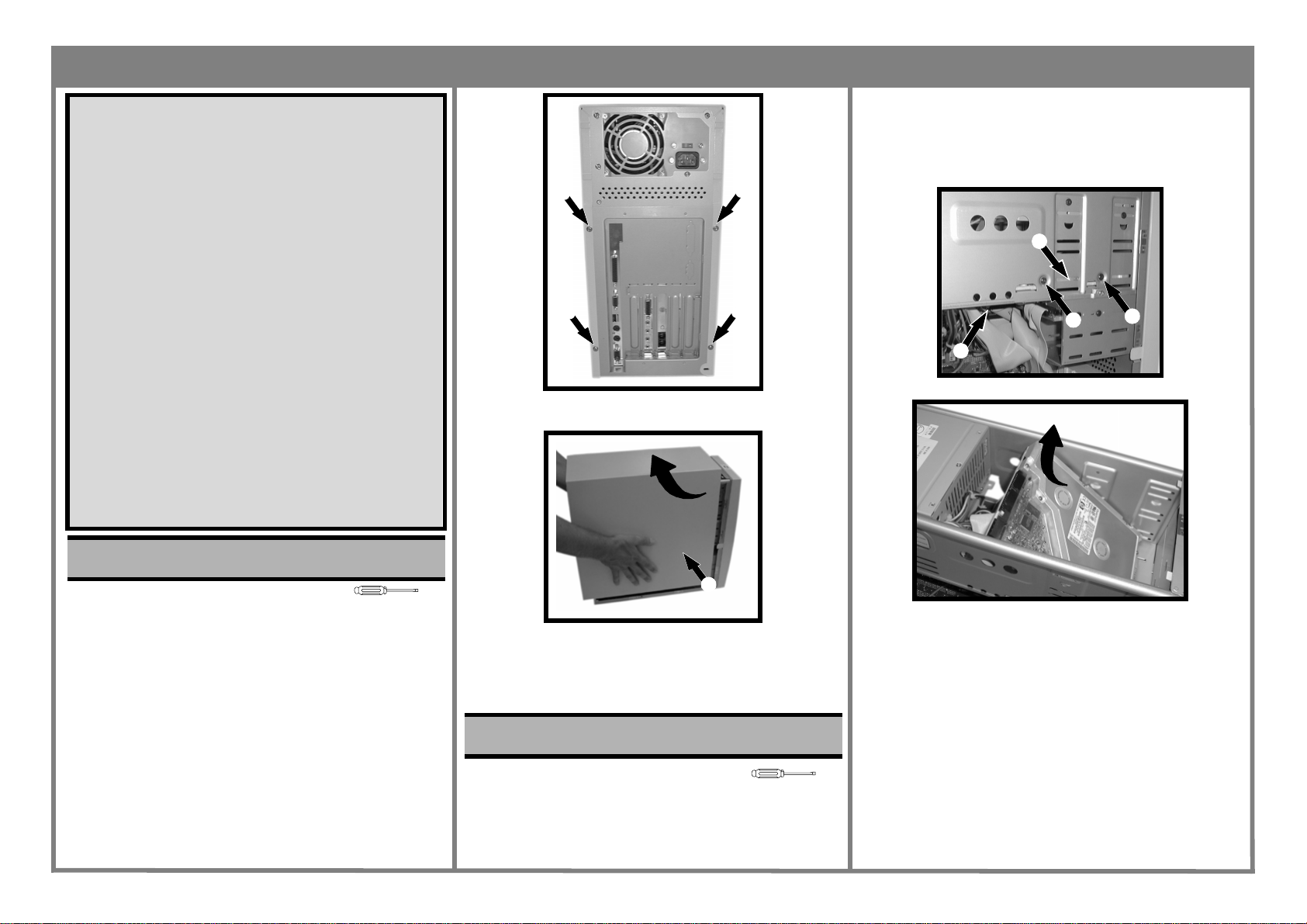
3. Slide the cover towards the back of the computer and
lift off ❷.
❶
❶
Page 1 of 4
Replacing a 5.25” Hard Disk
1. Remove any drives above the hard disk (CD-ROM, for
example — see Task 3 “Replacing the CD-ROM Drive”)
2. Locate the hard drive ❶, remove the cables ❷ and then
the screws ❸ on either side of the bay.
❶
➌
❷
3. Slide the hard drive upwards then out of the computer.
➌
Task 1 Replacing the Cover
Before You Start
• For your safety, disconnect the power cord and all other
external cables.
• Rest the computer on a flat surface, such as a desk.
Replacing the Cover
1. Rotate the computer so that you are looking at the back
of it.
2. Locate and remove the four screws ❶.
T-15
❷
4. Place the new cover over the computer and push in
both sides.
5. Slide the cover forward until it is firmly seated.
6. Replace the four screws.
Task 2 Replacing the Hard Disk
Before You Start
• Remove the computer’s cover as described in Task 1
“Replacing the Cover”.
4. Put the new hard drive into the bay, replace the four
screws and the cables.
5. Replace any drives above the hard disk.
6. Replace the cover.
T-15
Page 2
HP Brio PC 80xx/82xx
Replacing a 3.5” Hard Disk
1. Locate the hard drive ❶, remove the cables ❷ and then
the screws ❸ on either side of the bay.
❶
❷
2. Slide the hard drive towards the back and then out of
the computer.
3. Put the new hard drive into the bay, replace the four
screws and the cables.
4. Replace the cover.
Task 3 Replacing the CD-ROM Drive
➌
➌
4. Slide the drive towards the front of the computer and
lift out.
5. Slide the new drive into the bay and replace the four
screws ❷.
6. Reconnect the three cables ❶.
7. Replace the cover.
Task 4 Replacing the System Board
Before You Start
• Remove the computer’s cover as described in Task 1
“Replacing the Cover”.
Replacing the System Board
1. Disconnect all cables from the system board slide it out
of the computer.
2. Remove all expansion cards (see Task 8 “Replacing
Expansion Cards”) and then the expansion riser by
removing the two screws ❶ and lifting it out of its
socket.
T-15
Page 2 of 4
82xx
❶
❶
❷
3. Locate and remove the memory ❷, see Task 6 “Replac-
ing SIMMs/DIMMs”.
4. Un-clip the heatsink ❸, raise the lever ❹ and lift the
processor out.
Before You Start
• Remove the computer’s cover as described in Task 1
“Replacing the Cover”.
Replacing the CD-ROM Drive
1. Locate the CD-ROM drive.
2. Disconnect the three cables ❶.
❷
❷
❷
❶
3. Remove the four screws, two on each side ❷.
❷
T-15
❶
❶
❺
❷
80xx
❸
❹
5. Remove the two VRAM chips ❺, using the special tool
(part number 5041-2553), by pushing it firmly into the
holes at the ends of the chips and pulling up.
Page 3

HP Brio PC 80xx/82xx
❺
❺
6. Locate and remove the screws ❻.
❻
❻
❻
80xx
10. Replace the card that holds the expansion cards, then
replace the expansion cards.
11. Slide the system board back into the computer and
replace the screws.
12. Replace all cables into their appropriate sockets.
13. Replace the cover.
Task 5 Replacing the Floppy Disk
Drive
Before You Start
• Remove the computer’s cover as described in Task 1
“Replacing the Cover”.
• Slide the system board chassis out, as described in Task
4 “Replacing the System Board”.
Replacing the Floppy Disk Drive
1. Locate the Floppy Disk drive.
2. Remove the cables ❶.
T-15
Page 3 of 4
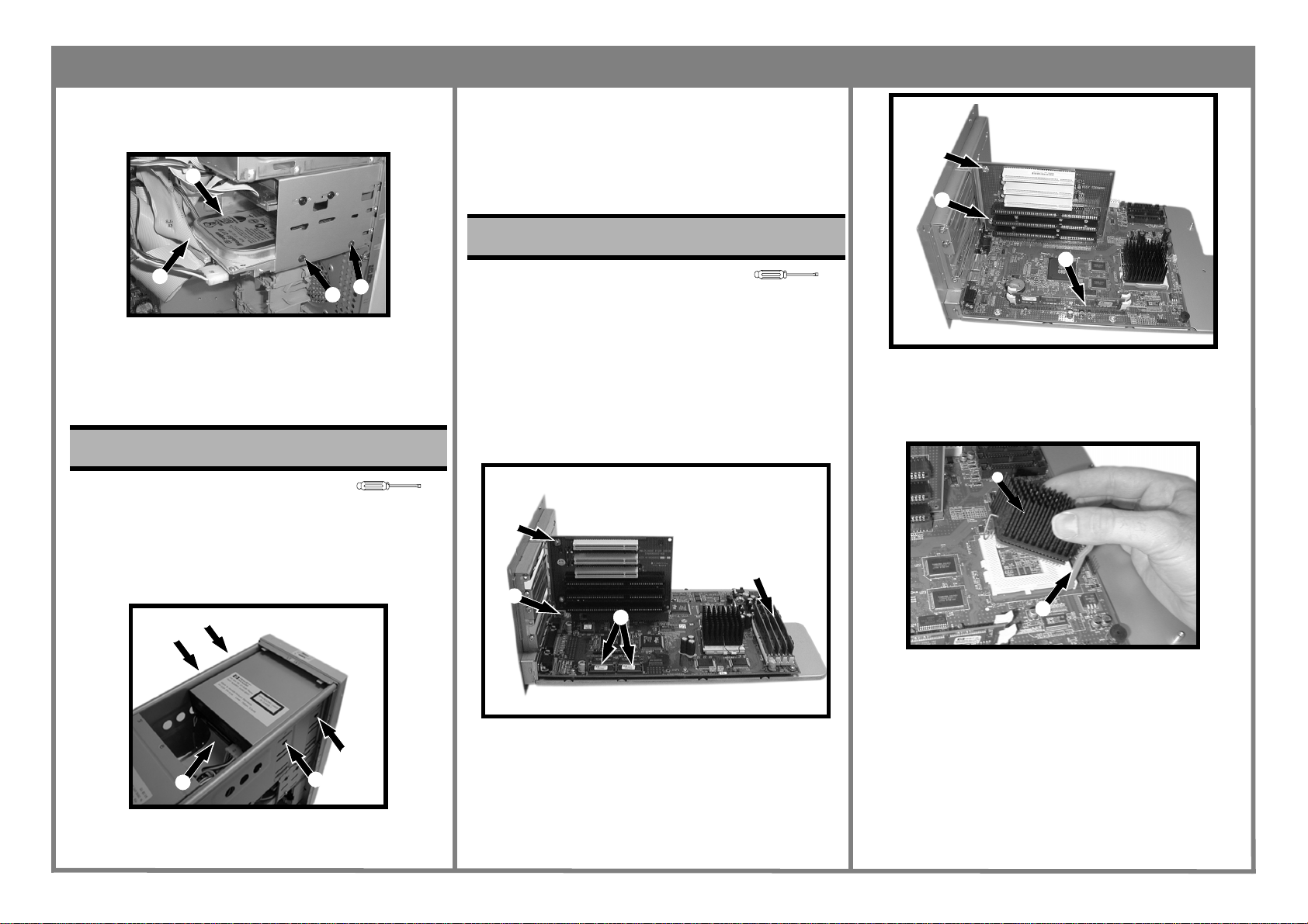
Task 6 Replacing SIMMs/DIMMs
Before You Start
• Remove the computer’s cover as described in Task 1
“Replacing the Cover”.
• Take out the system board as described in Task 4
“Replacing the System Board”.
Replacing SIMMs/DIMMs
1. Locate the SIMMs/DIMMs on your system board.
2. Press out the two retaining clips ❶.
80xx
❶
❶
T-15
❻
❻
❻
82xx
❻
❻
7. Replace the system board.
8. Replace the screws ❻.
9. Replace the memory ❷, processor and VRAM ❺.
❻
❻
❶
3. Remove the four screws ❷, two on either side.
4. Slide the Floppy Disk Drive backwards and out of the
computer.
5. Replace the Floppy Disk Drive.
6. Replace the four screws ❷.
7. Refit the two cables ❶.
8. Replace the cover.
❷
❷
82xx
❶
3. Holding the SIMM/DIMM by its edges, lift it clear of the
socket.
4. Replace the SIMM/DIMM, pushing it home until the
retaining clips ❶ lock it in place.
5. Replace the cover.
❶
Page 4

HP Brio PC 80xx/82xx
Task 7 Replacing the Power Supply
Page 4 of 4
5. Replace the cover.
6. Ensure the voltage selector switch is set to the correct
value for the country you live in.
Before You Start
• Remove the computer’s cover as described in in Task 1
“Replacing the Cover”
T-15 & +
Replacing the Power Supply
1. Locate and remove the four screws ❶ on the back of
the computer.
❶
❶
2. Disconnect all the white connectors ❷ on the system
board and drives.
❶
❶
❸
❷
3. Lift the power supply ❸ up and away from the com-
puter and replace with new power supply.
4. Replace the four screws ❶ and reconnect all connec-
tors ❷.
Task 8 Replacing Expansion Cards
Before You Start
• Remove the computer’s cover as described in Task 1
“Replacing the Cover”.
• Remove the system board as described in Task 4
“Replacing the System Board”.
Replacing Expansion Cards
1. Locate the expansion card and remove the retaining
screw ❶.
❶
2. If necessary, remove any cables to the expansion card
(audio cable, for example).
3. Carefully lift out the expansion card, making sure that
it does not make contact with any other part of the
computer.
4. Insert the replacement expansion card into the appro-
priate slot, and refit any cables if necessary.
5. Replace the retaining screw ❶.
6. Replace the system board.
7. Replace the cover.
T-15
Part Number 5967-9546-EN
 Loading...