

Page 1

HP VISUALIZE B1000/C3000 Owner’s Guide
HP VISUALIZE Computers
Printed in USA February 1999
Manufacturing Part Number: HP Part No. A4985-90013
Edition E0299
Page 2

© Copyright 1999 Hewlett-Packard Company
Notice
UNIX is a registered trademark in the United States and other
countries, licensed exclusively through X/Open Company Limited.
The information contained in this document is subject to change without
notice.
Hewlett-Packard assumes no responsibility for the use or reliability of its
software on equipment that is not furnished by Hewlett-Packard.
This document contains proprietary information that is protected by
copyright. All rights reserved. No part of this document may be
photocopied, reproduced or translated to another language without the
prior written consent of Hewlett-Packard Company.
HEWLETT-PACKARD WARRANTY STATEMENT
HP PRODUCT DURATION OF WARRANTY
HP VISUALIZE B1000/C3000 Computers 1 Year
1. HP warrants HP hardware, accessories and supplies against defects
in materials and workmanship for the period specified above. If HP
receives notice of such defects during the warranty period, HP will, at
its option, either repair or replace products which prove to be
defective. Replacement products may be either new or like-new.
2. HP warrants that HP software will not fail to execute its
programming instructions, for the period specified above, due to
defects in material and workmanship when properly installed and
used. If HP receives notice of such defects during the warranty
period, HP will replace software media which does not execute its
programming instructions due to such defects.
2
Page 3

3. HP does not warrant that the operation of HP products will be
uninterrupted or error free. If HP is unable,within a reasonable time,
to repair or replace any product to a condition as warranted, the
customer will be entitled to a refund of the purchase price upon
prompt return of the product.
4. HP products may contain remanufactured parts equivalent to new in
performance or may have been subject to incidental use.
5. The warranty period begins on the date of delivery or on the date of
installation if installed by HP. If customer schedules installation or
causes installation by HP to be delayed more than 30 days after
delivery, warranty begins on the 31st day from delivery.
6. Warranty does not apply to defects resulting from (a) improper or
inadequate maintenance or calibration, (b) software, interfacing,
parts or supplies not supplied by HP, (c) unauthorized modification or
misuse, (d) operation outside of the published environmental
specifications for the product, or (e) improper site preparation or
maintenance.
7. TO THE EXTENT ALLOWED BY LOCAL LAW, THE ABOVE
WARRANTIES ARE EXCLUSIVE AND NO OTHER WARRANTY
OR CONDITION, WHETHER WRITTEN OR ORAL, IS
EXPRESSED OR IMPLIED AND HP SPECIFICALLY DISCLAIMS
ANY IMPLIED WARRANTIES OR CONDITIONS OF
MERCHANTABILITY, SATISFACTORY QUALITY, AND FITNESS
FOR A PARTICULAR PURPOSE.
8. HP will be liable for damage to tangible property per incident up to
the greater of $300,000 or the actual amount paid for the product that
is the subject of the claim, and for damages for bodily injury or death,
to the extent that all such damages are determined by a court of
competent jurisdiction to have been directly caused by a defective HP
product.
9. TO THE EXTENT ALLOWED BY LOCAL LAW, THE REMEDIES IN
THIS WARRANTY STATEMENT ARE CUSTOMER’S SOLE AND
EXCLUSIVE REMEDIES. EXCEPT AS INDICATED ABOVE, IN
NO EVENT WILL HP OR ITS SUPPLIERS BE LIABLE FOR LOSS
OF DATA OR FOR DIRECT, SPECIAL, INCIDENTAL,
CONSEQUENTIAL (INCLUDING LOST PROFIT OR DATA), OR
OTHER DAMAGE, WHETHER BASED IN CONTRACT, TORT, OR
OTHERWISE.
3
Page 4

FOR CONSUMER TRANSACTIONS IN AUSTRALIA AND NEW
ZEALAND: THE WARRANTY TERMS CONTAINED IN THIS
STATEMENT, EXCEPT TO THE EXTENT LAWFULLY
PERMITTED, DO NOT EXCLUDE, RESTRICT OR MODIFY AND
ARE IN ADDITION TO THE MANDATORY STATUTORY RIGHTS
APPLICABLE TO THE SALE OF THIS PRODUCT TO YOU.
RESTRICTED RIGHTS LEGEND. Use, duplication, or disclosure by the
U.S. government is subject to restrictions as set forth in subdivision (c)
(1) (ii) of the Rights in Technical Data and Computer Software Clause in
DFARS252.227.7013.Hewlett-Packard Co., 3000 Hanover St., Palo Alto,
CA 94304.
4
Page 5

Contents
1. System Overview
Product Description. . . . . . . . . . . . . . . . . . . . . . . . . . . . . . . . . . . . . . . . . .23
System Unit Front Panel and Removable Devices . . . . . . . . . . . . . . . . .25
System LCD . . . . . . . . . . . . . . . . . . . . . . . . . . . . . . . . . . . . . . . . . . . . . .26
System Power Switch. . . . . . . . . . . . . . . . . . . . . . . . . . . . . . . . . . . . . . .26
Removable Media Devices . . . . . . . . . . . . . . . . . . . . . . . . . . . . . . . . . . .27
System Unit Rear Panel Connectors . . . . . . . . . . . . . . . . . . . . . . . . . . . .28
Audio Connectors . . . . . . . . . . . . . . . . . . . . . . . . . . . . . . . . . . . . . . . . . .30
USB Connectors . . . . . . . . . . . . . . . . . . . . . . . . . . . . . . . . . . . . . . . . . . .31
HP Parallel I/O Connector. . . . . . . . . . . . . . . . . . . . . . . . . . . . . . . . . . .32
802.3 Network Connectors. . . . . . . . . . . . . . . . . . . . . . . . . . . . . . . . . . .32
RS-232C Serial Input/Output Connector . . . . . . . . . . . . . . . . . . . . . . .33
SCSI Connectors. . . . . . . . . . . . . . . . . . . . . . . . . . . . . . . . . . . . . . . . . . .34
Power Cord Connector . . . . . . . . . . . . . . . . . . . . . . . . . . . . . . . . . . . . . .34
Security Loop. . . . . . . . . . . . . . . . . . . . . . . . . . . . . . . . . . . . . . . . . . . . . . .35
Locking Your System Unit’s Left-Side Panel . . . . . . . . . . . . . . . . . . . .36
Memory. . . . . . . . . . . . . . . . . . . . . . . . . . . . . . . . . . . . . . . . . . . . . . . . . . . .37
Monitors. . . . . . . . . . . . . . . . . . . . . . . . . . . . . . . . . . . . . . . . . . . . . . . . . . .38
Operating System Overview. . . . . . . . . . . . . . . . . . . . . . . . . . . . . . . . . . .39
Information You Need to Record. . . . . . . . . . . . . . . . . . . . . . . . . . . . . . . .40
LAN Station ID. . . . . . . . . . . . . . . . . . . . . . . . . . . . . . . . . . . . . . . . . . . .40
IP Address and Subnetwork Mask Information. . . . . . . . . . . . . . . . . .40
Powering Up Your System. . . . . . . . . . . . . . . . . . . . . . . . . . . . . . . . . . . . .41
Getting Required Information. . . . . . . . . . . . . . . . . . . . . . . . . . . . . . . .42
Turning on the Power. . . . . . . . . . . . . . . . . . . . . . . . . . . . . . . . . . . . . . .44
Documentation . . . . . . . . . . . . . . . . . . . . . . . . . . . . . . . . . . . . . . . . . . . .45
5
Page 6

Contents
2. Using Your CD Drive
CD Media Description . . . . . . . . . . . . . . . . . . . . . . . . . . . . . . . . . . . . . . . 49
Caring for CDs. . . . . . . . . . . . . . . . . . . . . . . . . . . . . . . . . . . . . . . . . . . . 49
Operating the CD Drive. . . . . . . . . . . . . . . . . . . . . . . . . . . . . . . . . . . . . . 50
CD Drive . . . . . . . . . . . . . . . . . . . . . . . . . . . . . . . . . . . . . . . . . . . . . . . . 50
Loading and Unloading a CD. . . . . . . . . . . . . . . . . . . . . . . . . . . . . . . . 52
Locating Help . . . . . . . . . . . . . . . . . . . . . . . . . . . . . . . . . . . . . . . . . . . . 54
Mounting and Unmounting a CD . . . . . . . . . . . . . . . . . . . . . . . . . . . . . . 55
Mounting a CD Using SAM . . . . . . . . . . . . . . . . . . . . . . . . . . . . . . . . . 55
Unmounting a CD Using SAM. . . . . . . . . . . . . . . . . . . . . . . . . . . . . . . 58
Verifying the CD Drive Operation. . . . . . . . . . . . . . . . . . . . . . . . . . . . . . 61
Configuring the CD Driver . . . . . . . . . . . . . . . . . . . . . . . . . . . . . . . . . . . 62
Audio Control for the CD Drive. . . . . . . . . . . . . . . . . . . . . . . . . . . . . . . . 63
Installing the xmcd Utility. . . . . . . . . . . . . . . . . . . . . . . . . . . . . . . . . . 63
Using the xmcd Utility . . . . . . . . . . . . . . . . . . . . . . . . . . . . . . . . . . . . . 64
3. Using Your 3.5-Inch Floppy Disk Drive
Operating the Floppy Drive. . . . . . . . . . . . . . . . . . . . . . . . . . . . . . . . . . . 69
Floppy Disk Drive. . . . . . . . . . . . . . . . . . . . . . . . . . . . . . . . . . . . . . . . . 69
Using the Floppy Diskette . . . . . . . . . . . . . . . . . . . . . . . . . . . . . . . . . . 70
Using Device Files. . . . . . . . . . . . . . . . . . . . . . . . . . . . . . . . . . . . . . . . . 71
Formatting a New Diskette . . . . . . . . . . . . . . . . . . . . . . . . . . . . . . . . . 74
Transferring Data To and From a Floppy Diskette . . . . . . . . . . . . . . 75
Listing the Files on a Floppy Diskette. . . . . . . . . . . . . . . . . . . . . . . . . 76
Troubleshooting. . . . . . . . . . . . . . . . . . . . . . . . . . . . . . . . . . . . . . . . . . . 76
Verifying the Floppy Drive Configuration. . . . . . . . . . . . . . . . . . . . . . . . 77
Additional Floppy Drive Information . . . . . . . . . . . . . . . . . . . . . . . . . . . 78
Configuring the Floppy Driver. . . . . . . . . . . . . . . . . . . . . . . . . . . . . . . 78
6
Page 7

Contents
For More Information. . . . . . . . . . . . . . . . . . . . . . . . . . . . . . . . . . . . . . .78
4. SCSI Connections
SCSI Bus Differences . . . . . . . . . . . . . . . . . . . . . . . . . . . . . . . . . . . . . . . .83
SCSI Restrictions. . . . . . . . . . . . . . . . . . . . . . . . . . . . . . . . . . . . . . . . . . . .84
Cables . . . . . . . . . . . . . . . . . . . . . . . . . . . . . . . . . . . . . . . . . . . . . . . . . . .84
Terminators . . . . . . . . . . . . . . . . . . . . . . . . . . . . . . . . . . . . . . . . . . . . . .86
Number of Devices Per SCSI Bus . . . . . . . . . . . . . . . . . . . . . . . . . . . . .86
Considerations for Selecting SCSI Devices. . . . . . . . . . . . . . . . . . . . . .86
SCSI Bus Length Constraints. . . . . . . . . . . . . . . . . . . . . . . . . . . . . . . . . .88
Ultra Narrow Single-Ended SCSI Bus Length. . . . . . . . . . . . . . . . . . .88
Ultra2 Wide Low-Voltage Differential SCSI Bus Length. . . . . . . . . . .89
Assigning SCSI Device IDs. . . . . . . . . . . . . . . . . . . . . . . . . . . . . . . . . . . .90
Assigning Ultra Narrow Single-Ended SCSI Device IDs. . . . . . . . . . .91
Assigning Ultra2 Wide Low-Voltage Differential SCSI Device IDs . .92
Connecting to the SCSI Ports . . . . . . . . . . . . . . . . . . . . . . . . . . . . . . . . . .93
System SCSI Port Connection. . . . . . . . . . . . . . . . . . . . . . . . . . . . . . . .93
5. Changing Your Computer Hardware Configuration
System Unit Front Panel. . . . . . . . . . . . . . . . . . . . . . . . . . . . . . . . . . . . . .98
Opening the System Unit Front Panel . . . . . . . . . . . . . . . . . . . . . . . . .98
Closing the System Unit Front Panel . . . . . . . . . . . . . . . . . . . . . . . . . .99
Left Side Panel of the System Unit . . . . . . . . . . . . . . . . . . . . . . . . . . . .100
Opening the Left Side Panel of the System Unit . . . . . . . . . . . . . . . .100
Closing the Left Side Panel of the System Unit. . . . . . . . . . . . . . . . .102
System Unit Power Supply. . . . . . . . . . . . . . . . . . . . . . . . . . . . . . . . . . .103
Propping Up the Power Supply . . . . . . . . . . . . . . . . . . . . . . . . . . . . . .103
I/O Cards . . . . . . . . . . . . . . . . . . . . . . . . . . . . . . . . . . . . . . . . . . . . . . . . .106
7
Page 8

Contents
Removing I/O Cards . . . . . . . . . . . . . . . . . . . . . . . . . . . . . . . . . . . . . . 107
Installing I/O Cards . . . . . . . . . . . . . . . . . . . . . . . . . . . . . . . . . . . . . . 109
System Unit Fans. . . . . . . . . . . . . . . . . . . . . . . . . . . . . . . . . . . . . . . . . . 110
Removing the Fan from the Hard Disk Drive Area . . . . . . . . . . . . . 111
Replacing the Hard Disk Drive Fan. . . . . . . . . . . . . . . . . . . . . . . . . . 113
Removable Media Devices . . . . . . . . . . . . . . . . . . . . . . . . . . . . . . . . . . . 114
Installing a CD Drive . . . . . . . . . . . . . . . . . . . . . . . . . . . . . . . . . . . . . 114
Removing a CD Drive . . . . . . . . . . . . . . . . . . . . . . . . . . . . . . . . . . . . . 120
Installing a Floppy Disk Drive. . . . . . . . . . . . . . . . . . . . . . . . . . . . . . 126
Removing a Floppy Disk Drive. . . . . . . . . . . . . . . . . . . . . . . . . . . . . . 133
Hard Disk Drives . . . . . . . . . . . . . . . . . . . . . . . . . . . . . . . . . . . . . . . . . . 140
Installing a Hard Disk Drive . . . . . . . . . . . . . . . . . . . . . . . . . . . . . . . 141
Removing a Hard Disk Drive . . . . . . . . . . . . . . . . . . . . . . . . . . . . . . . 144
Configuring a Hard Disk Drive as a File System . . . . . . . . . . . . . . . 148
Memory Cards . . . . . . . . . . . . . . . . . . . . . . . . . . . . . . . . . . . . . . . . . . . . 153
Installing Additional Memory . . . . . . . . . . . . . . . . . . . . . . . . . . . . . . 153
Removing Memory . . . . . . . . . . . . . . . . . . . . . . . . . . . . . . . . . . . . . . . 157
Changing Your Monitor Type . . . . . . . . . . . . . . . . . . . . . . . . . . . . . . . . 159
Setting the Monitor Type at Power On . . . . . . . . . . . . . . . . . . . . . . . 159
Setting the Monitor Type from the Boot Console Interface . . . . . . . 159
Setting the Monitor Type Using SAM . . . . . . . . . . . . . . . . . . . . . . . . 160
Troubleshooting Monitor Problems . . . . . . . . . . . . . . . . . . . . . . . . . . 163
6. The Boot Console Interface
Boot Console Interface Features . . . . . . . . . . . . . . . . . . . . . . . . . . . . . . 167
Accessing the Boot Console Interface . . . . . . . . . . . . . . . . . . . . . . . . . . 172
Booting Your Computer . . . . . . . . . . . . . . . . . . . . . . . . . . . . . . . . . . . . . 174
Searching for Bootable Media . . . . . . . . . . . . . . . . . . . . . . . . . . . . . . . . 177
8
Page 9

Contents
Resetting Your Computer . . . . . . . . . . . . . . . . . . . . . . . . . . . . . . . . . . . .178
Displaying and Setting Paths. . . . . . . . . . . . . . . . . . . . . . . . . . . . . . . . .179
Displaying and Setting the Monitor Type . . . . . . . . . . . . . . . . . . . . . . .181
The Monitor Command . . . . . . . . . . . . . . . . . . . . . . . . . . . . . . . . . . . .181
Displaying the Current Monitor Configuration . . . . . . . . . . . . . . . . .183
Setting the Monitor Type. . . . . . . . . . . . . . . . . . . . . . . . . . . . . . . . . . .184
Setting the Monitor Type with SAM. . . . . . . . . . . . . . . . . . . . . . . . . .185
Setting the Monitor Type at Power On. . . . . . . . . . . . . . . . . . . . . . . .188
Troubleshooting Monitor Problems. . . . . . . . . . . . . . . . . . . . . . . . . . .189
Changing the Console to an External Terminal . . . . . . . . . . . . . . . . . .190
Displaying the Current Memory Configuration. . . . . . . . . . . . . . . . . . .191
Memory Information Sample. . . . . . . . . . . . . . . . . . . . . . . . . . . . . . . .192
Displaying the Status of the System I/O . . . . . . . . . . . . . . . . . . . . . . . .193
Setting the Auto Boot and Auto Search Flags . . . . . . . . . . . . . . . . . . . .194
Displaying and Setting the Security Mode. . . . . . . . . . . . . . . . . . . . . . .196
Displaying and Setting the Fastboot Mode . . . . . . . . . . . . . . . . . . . . . .197
Displaying the LAN Station Address . . . . . . . . . . . . . . . . . . . . . . . . . . .198
Displaying System Information . . . . . . . . . . . . . . . . . . . . . . . . . . . . . . .199
7. Solving Problems
Common Problems and Solutions. . . . . . . . . . . . . . . . . . . . . . . . . . . . . .203
Dealing with a Boot Failure . . . . . . . . . . . . . . . . . . . . . . . . . . . . . . . . . .207
Memory Failures . . . . . . . . . . . . . . . . . . . . . . . . . . . . . . . . . . . . . . . . . . .209
LCD Information . . . . . . . . . . . . . . . . . . . . . . . . . . . . . . . . . . . . . . . . . . .210
LCD Fan Failures and Warnings. . . . . . . . . . . . . . . . . . . . . . . . . . . . .211
Troubleshooting Monitor Problems . . . . . . . . . . . . . . . . . . . . . . . . . . . .213
9
Page 10

Contents
Running System Verification Tests. . . . . . . . . . . . . . . . . . . . . . . . . . . . 214
A. Safety and Regulatory Statements
Declaration of Conformity . . . . . . . . . . . . . . . . . . . . . . . . . . . . . . . . . . . 217
Emissions Regulations. . . . . . . . . . . . . . . . . . . . . . . . . . . . . . . . . . . . . . 218
For FCC B Applications:. . . . . . . . . . . . . . . . . . . . . . . . . . . . . . . . . . . 218
EMI Class A RRL (Korea) . . . . . . . . . . . . . . . . . . . . . . . . . . . . . . . . . 219
VCCI Class B ITE (Japan) . . . . . . . . . . . . . . . . . . . . . . . . . . . . . . . . . 219
EMI Class A (Taiwan). . . . . . . . . . . . . . . . . . . . . . . . . . . . . . . . . . . . . 220
Special Video Configuration Statement. . . . . . . . . . . . . . . . . . . . . . . 220
Third Party Emissions Regulations Compliance . . . . . . . . . . . . . . . . . 221
Special Regulatory and Safety Information . . . . . . . . . . . . . . . . . . . . . 222
Acoustics . . . . . . . . . . . . . . . . . . . . . . . . . . . . . . . . . . . . . . . . . . . . . . . 222
Laser Safety Statement (U.S.A. Only). . . . . . . . . . . . . . . . . . . . . . . . 222
LEDs . . . . . . . . . . . . . . . . . . . . . . . . . . . . . . . . . . . . . . . . . . . . . . . . . . 222
Warnings and Cautions . . . . . . . . . . . . . . . . . . . . . . . . . . . . . . . . . . . . . 223
WARNING: . . . . . . . . . . . . . . . . . . . . . . . . . . . . . . . . . . . . . . . . . . . . . 223
WARNUNG: . . . . . . . . . . . . . . . . . . . . . . . . . . . . . . . . . . . . . . . . . . . . 223
AVERTISSEMENT: . . . . . . . . . . . . . . . . . . . . . . . . . . . . . . . . . . . . . . 223
WARNING: . . . . . . . . . . . . . . . . . . . . . . . . . . . . . . . . . . . . . . . . . . . . . 223
WARNUNG: . . . . . . . . . . . . . . . . . . . . . . . . . . . . . . . . . . . . . . . . . . . . 223
ADVERTISSEMENT:. . . . . . . . . . . . . . . . . . . . . . . . . . . . . . . . . . . . . 223
Glossary
10
Page 11

Figures
Figure 1-1. System Unit Front Panel Controls . . . . . . . . . . . . . . . . . . . .25
Figure 1-2. LCD Symbols HP VISUALIZE B1000/C3000 Features. . . . . .26
Figure 1-3. System Unit Rear Panel Connectors. . . . . . . . . . . . . . . . . . .29
Figure 1-4. Audio Connectors . . . . . . . . . . . . . . . . . . . . . . . . . . . . . . . . . .30
Figure 1-5. Security Loop Components . . . . . . . . . . . . . . . . . . . . . . . . . .35
Figure 1-6. Closed Left-Side Panel. . . . . . . . . . . . . . . . . . . . . . . . . . . . . .36
Figure 2-1. CD Drive Controls and Features. . . . . . . . . . . . . . . . . . . . . .51
Figure 2-2. Open CD Tray. . . . . . . . . . . . . . . . . . . . . . . . . . . . . . . . . . . . .52
Figure 2-3. Placing the CD in the Disk Tray . . . . . . . . . . . . . . . . . . . . . .53
Figure 2-4. Closed Disk Tray . . . . . . . . . . . . . . . . . . . . . . . . . . . . . . . . . .53
Figure 3-1. Floppy Disk Drive Controls and Features. . . . . . . . . . . . . . .69
Figure 3-2. Setting the Write-Protect Tab on a Floppy Diskette . . . . . .70
Figure 3-3. Inserting and Removing a Floppy Diskette . . . . . . . . . . . . .71
Figure 5-1. Opening the Front Panel . . . . . . . . . . . . . . . . . . . . . . . . . . . .98
Figure 5-2. Opening the Left Side Panel of the System Unit . . . . . . . .101
Figure 5-3. Unscrewing the Power Supply Captive Screws . . . . . . . . .103
Figure 5-4. Propping Up the Power Supply . . . . . . . . . . . . . . . . . . . . . .104
Figure 5-5. PCI Card Slot Numbering and Capabilities . . . . . . . . . . . .106
Figure 5-6. I/O Slot Numbering . . . . . . . . . . . . . . . . . . . . . . . . . . . . . . .107
Figure 5-7. Removing the I/O Card Retainer. . . . . . . . . . . . . . . . . . . . .108
Figure 5-8. Removing the I/O Card. . . . . . . . . . . . . . . . . . . . . . . . . . . . .108
Figure 5-9. Fan Cooling Areas for the System Unit . . . . . . . . . . . . . . .110
Figure 5-10. Removing the Fan from the Hard Disk Drive Chassis. . .112
11
Page 12

Figures
Figure 5-11. Removing the CD Drive Bay’s Rear Cover . . . . . . . . . . . 115
Figure 5-12. Front of System Unit with the Front Panel Removed. . . 115
Figure 5-13. Removing the CD Drive Bracket and Blank . . . . . . . . . . 116
Figure 5-14. Installing the CD Drive . . . . . . . . . . . . . . . . . . . . . . . . . . 117
Figure 5-15. Plugging in the Audio, ATAPI and Power Cables. . . . . . 118
Figure 5-16. Tightening the Bracket Screws . . . . . . . . . . . . . . . . . . . . 118
Figure 5-17. Replacing the CD Drive Bay’s Rear Cover. . . . . . . . . . . . 119
Figure 5-18. Removing the CD Drive Bay’s Rear Cover . . . . . . . . . . . 121
Figure 5-19. Front of the System Unit with the Front Panel Removed122
Figure 5-20. Removing the CD Drive . . . . . . . . . . . . . . . . . . . . . . . . . . 123
Figure 5-21. Installing the CD Drive Blank. . . . . . . . . . . . . . . . . . . . . 124
Figure 5-22. Tightening the Bracket Screws . . . . . . . . . . . . . . . . . . . . 125
Figure 5-23. Replacing the CD Drive Bay’s Rear Cover. . . . . . . . . . . . 125
Figure 5-24. Removing the Floppy Disk Drive Bay’s Rear Cover . . . . 127
Figure 5-25. Front of System Unit with the Front Panel Removed. . . 128
Figure 5-26. Removing the Floppy Disk Bracket and Blank. . . . . . . . 129
Figure 5-27. Installing the Floppy Disk Drive . . . . . . . . . . . . . . . . . . . 130
Figure 5-28. Plugging In the Floppy Data and Power Cables. . . . . . . 131
Figure 5-29. Tightening the Bracket Screws . . . . . . . . . . . . . . . . . . . . 131
Figure 5-30. Replacing the Floppy Disk Drive Bay’s Rear Cover . . . . 132
Figure 5-31. Removing the Floppy Disk Drive Bay’s Rear Cover . . . . 134
Figure 5-32. Front of System Unit with the Front Panel Removed. . . 135
Figure 5-33. Removing the Floppy Disk Drive. . . . . . . . . . . . . . . . . . . 136
12
Page 13

Figures
Figure 5-34. Installing the Floppy Disk Blank and Bracket. . . . . . . . .137
Figure 5-35. Tightening the Bracket Screws . . . . . . . . . . . . . . . . . . . . .138
Figure 5-36. Replacing the Rear Floppy Disk Drive Bay’s Cover. . . . .138
Figure 5-37. The Hard Drive Slots . . . . . . . . . . . . . . . . . . . . . . . . . . . . .141
Figure 5-38. Removing the Hard Drive Bracket . . . . . . . . . . . . . . . . . .142
Figure 5-39. Inserting the Hard Disk Drive. . . . . . . . . . . . . . . . . . . . . .143
Figure 5-40. The Hard Drive Slots . . . . . . . . . . . . . . . . . . . . . . . . . . . . .144
Figure 5-41. Removing the Hard Disk Drive . . . . . . . . . . . . . . . . . . . . .145
Figure 5-42. Removing the Hard Disk Drive from Its Bracket. . . . . . .146
Figure 5-43. Replacing the Hard Disk Drive Bracket . . . . . . . . . . . . . .147
Figure 5-44. Propping Up the Power Supply . . . . . . . . . . . . . . . . . . . . .154
Figure 5-45. Memory Card Slot Numbers and Loading Sequence . . . .155
Figure 5-46. Installing Memory Cards. . . . . . . . . . . . . . . . . . . . . . . . . .156
Figure 5-47. Propping Up the Power Supply . . . . . . . . . . . . . . . . . . . . .157
Figure 5-48. Removing Memory Cards. . . . . . . . . . . . . . . . . . . . . . . . . .158
Figure 7-1. Fan Locations . . . . . . . . . . . . . . . . . . . . . . . . . . . . . . . . . . . .212
13
Page 14

Figures
14
Page 15

Tables
Table 1-1. HP VISUALIZE B1000/C3000 Features. . . . . . . . . . . . . . . . . . .23
Table 1-2. Audio Electrical Specifications . . . . . . . . . . . . . . . . . . . . . . . .31
Table 1-3. Serial I/O Pins . . . . . . . . . . . . . . . . . . . . . . . . . . . . . . . . . . . . .33
Table 2-1. CD Drive Operating Controls and Features . . . . . . . . . . . . . .51
Table 3-1. Floppy Disk Drive Operating Controls and Features . . . . . .69
Table 4-1. SCSI Bus Differences. . . . . . . . . . . . . . . . . . . . . . . . . . . . . . . .83
Table 4-2. Ultra Narrow Single-Ended SCSI Cables. . . . . . . . . . . . . . . .84
Table 4-3. Ultra2 Wide Low-Voltage Differential SCSI Cables. . . . . . . .85
Table 6-1. System Paths . . . . . . . . . . . . . . . . . . . . . . . . . . . . . . . . . . . . .179
Table 6-2. Mnemonic Style Notation for Boot Paths . . . . . . . . . . . . . . .179
Table 7-1. Problems Powering Up the System. . . . . . . . . . . . . . . . . . . .203
Table 7-2. Problems Loading and Booting the Operating System . . . .204
Table 7-3. Problems with the 802.3 Network. . . . . . . . . . . . . . . . . . . . .204
Table 7-4. Problems Using a Hard Disk Drive. . . . . . . . . . . . . . . . . . . .205
Table 7-5. Problems Using the CD Drive. . . . . . . . . . . . . . . . . . . . . . . .205
Table 7-6. Problems Using the Floppy Disk Drive. . . . . . . . . . . . . . . . .206
Table 7-7. Fan Numbers and Their Names . . . . . . . . . . . . . . . . . . . . . .211
Table A-1. Regulation On Noise Declaration For Machines -3. GSGV .222
15
Page 16

Tables
16
Page 17

Preface
This owner’s guide describes how to use your HP VISUALIZE
B1000/C3000 computer.
This manual assumes that you have installed your computer as
described in the HP VISUALIZE B1000/C3000 Installation Card.
Audience
This guide is intended for HP VISUALIZE B1000/C3000 computer users.
Safety and Regulatory Statements
See Appendix A for the safety and regulatory statements that apply to
the HP VISUALIZE B1000/C3000 computer.
17
Page 18

Installation Notice
Products designated in the applicable Hewlett-Packard price list as
customer-installable can be installed by computer-knowledgeable
customers who carefully read and follow the instructions provided.
Customers who elect to have the product installed by our field personnel
are charged the applicable field installation charge, as covered under the
standard terms and conditions. For more information, please contact
your local sales representative.
Related Manuals
For more information, refer to the following documents:
• Configuring HP-UX for Peripherals
• HP-UX System Administration Tasks
• HP CDE Getting Started Guide
• Managing Systems and Workstations
• Using HP-UX.
• Using Your HP Workstation
Note that the documents listed above can be viewed with a web browser
using this URL:
http://www.docs.hp.com
18
Page 19

Revision History
The revision history for each edition of the manual is listed below:
Edition Revision History
E0299 First Printing
Problems, Questions, and Suggestions
If you have any problems or questions with our hardware, software, or
documentation, please contact either your HP Response Center or your
local HP representative. If you have access to a web browser, you can get
the latest software and hardware patches at the following URL:
http://us-support.external.hp.com/
19
Page 20

Documentation Conventions
Unless otherwise noted in the text, this guide uses the following symbolic
conventions.
user-supplied values Italic words or characters in syntax and command
descriptions represent values that you must supply.
Italics are also used in text for emphasis.
screen display Information that the system displays, commands that
you must use literally, and path names appear in this
typeface.
Enter
Keycaps are presented with a special keycap font as
shown in the left column. (In this document, we refer
to the Enter key. On your keyboard, the key may be
labeled either Enter or Return.)
Electrostatic Discharge (ESD) Precautions
Electrostatic charges can damage the integrated circuits on printed
circuit boards. To prevent such damage from occurring, observe the
following precautions during board unpacking and installation:
• Stand on a static-free mat.
• Wear a static strap to ensure that any accumulated electrostatic
charge is discharged from your body to ground.
• Create a common ground for the equipment you are working on by
connecting the static-free mat, static strap, routing nodes, and
peripheral units to that piece of equipment.
• Keep uninstalled printed circuit boards in their protective antistatic
bags.
• Handle printed circuit boards by their edges, once you have removed
them from their protective antistatic bags.
20
Page 21

1 System Overview
This chapter introduces the HP VISUALIZE B1000/C3000 computer. Its
purpose is to familiarize you with your computer and its controls and
indicators.
21
Page 22

System Overview
Instructions in this chapter assume that you are using the HP-UX 10.20
operating system and the Workstation Additional Core Enhancements
(ACE) for HP-UX 10.20 (June 1999) with the HP CDE interface. Note
that the HP-UX 10.20 operating system is a Year 2000 compliant
operating system.
The topics included in this chapter are:
• Product Description
• System Unit Front Panel and Removable Devices
• System Unit Rear Panel Connectors
• Monitors
• Operating System Overview
• Information You Need to Record
• Powering Up Your System.
22 Chapter1
Page 23

Product Description
To help you gain a better understanding of the HP VISUALIZE
B1000/C3000 computer, Table 1-1 provides the computer’s key features.
Table 1-1 HP VISUALIZE B1000/C3000 Features
Computer Feature Description
Processor PA8500 with operating frequencies of
300MHz for the B1000 and 400MHz for the
C3000. This processor has a 0.5Mbyte
instruction cache and a 1.0Mbyte data cache.
Operating System HP-UX 10.20 and Workstation ACE for
HP-UX 10.20 (June 1999)
User Interface HP CDE graphical user interface
Compatibility Source and binary code compatible with the
B and C Class product family
System Overview
Product Description
Monitors List of compatible monitors:
• 19 inch, 1280x1024 and 1600x1200
color, 75Hz
• 21 inch, 1280x1024 (stereo capability)
and 1600x1200 color, 75Hz
Optional Graphics Supported graphics devices:
•HPVISUALIZE-EG and VISUALIZE-fx
Pro (for B1000)
•HPVISUALIZE-EG, VISUALIZE-fx2Pro
and VISUALIZE-fx4Pro (for C3000)
Main Memory The B1000 and C3000 computers use 128
MByte and 256 MByte DIMMs to provide a
minimum of 128 MBytes and a maximum of
2GBytes of memory. These computers each
have eight memory slots.
Chapter 1 23
2
Page 24
System Overview
Product Description
Table 1-1 HP VISUALIZE B1000/C3000 Features
Computer Feature Description
Internal Storage Devices Ultra2 WideLow-Voltage Differential (LVD)
SCSI hard disk drive(s) and a choice of either
a floppy disk drive or CD drive or both.
Standard Network RJ45, Twisted Pair 10 BaseT/100 BaseT
Standard I/O Standard computer I/O ports:
• Ultra2 Wide Low-Voltage Differential
(LVD) SCSI, one
• Ultra Narrow Single-Ended (NSE) SCSI,
one
• Parallel port (IEEE 1284), one
• Universal Serial Bus (USB) ports, two
• Serial interface ports (RS-232C), two
• Audio ports (Line in, line out, headset,
and microphone in)
PCI slots Slot 1: 64 Bit, 5.0V, 33MHz
Slot 2: Primary Graphics, 64 Bit,
3.3V, 66MHz
Slot 3: 64 Bit, 5.0V, 33MHz
Slot 4: Secondary Graphics, 64 Bit,
5.0V, 33MHz
Slot 5: 32 Bit, 5.0V, 33MHz
Slot 6: 32 Bit, 5.0V, 33MHz
Keyboard Universal Serial Bus (USB) keyboard
Mouse Universal Serial Bus (USB) mouse
24 Chapter1
Page 25
System Unit Front Panel and Removable Devices
System Unit Front Panel and Removable
Devices
Before powering on your system, you should become familiar with the
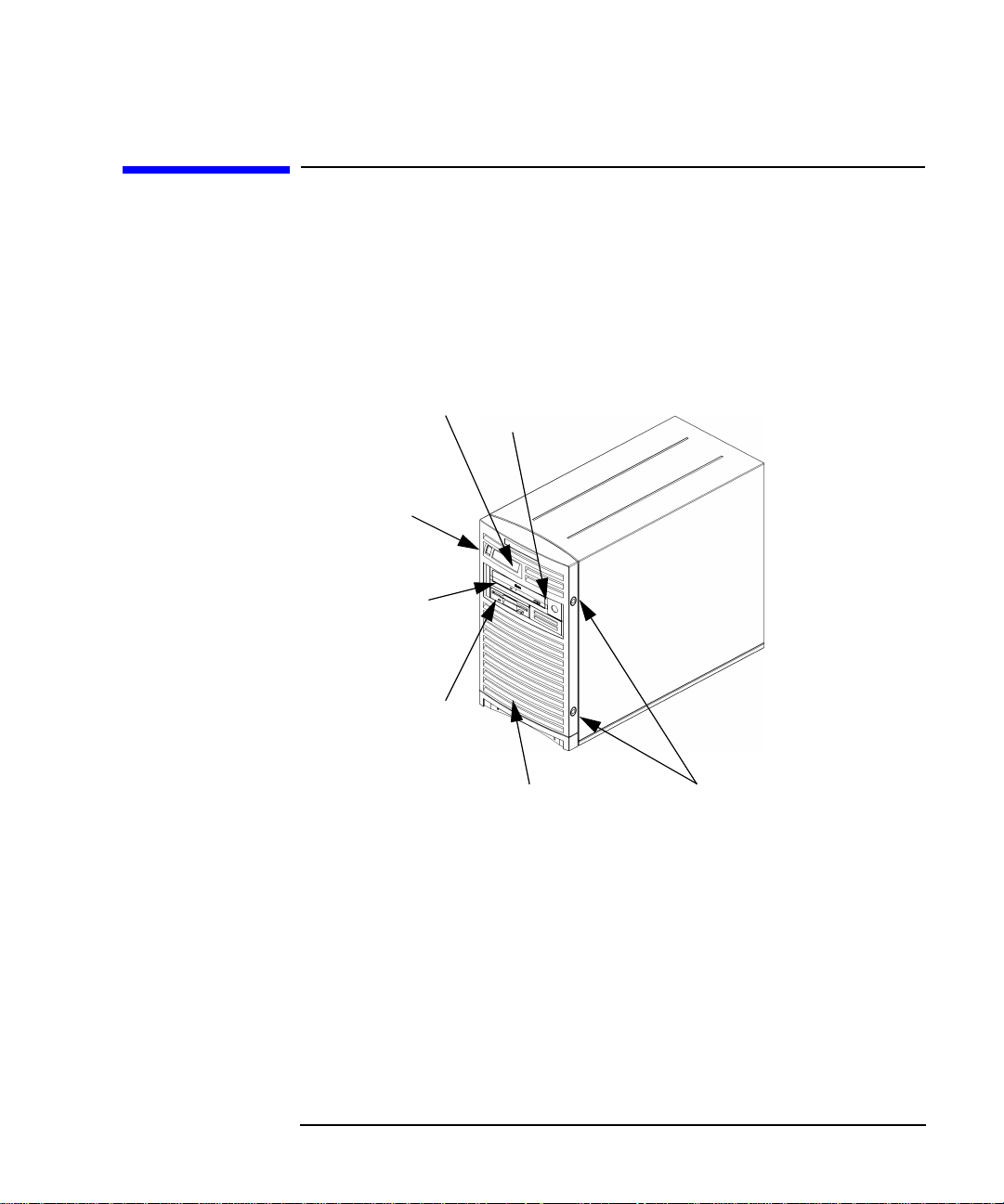
system unit controls. Figure 1-1 shows the system unit front panel
controls.
Figure 1-1 System Unit Front Panel Controls
System Overview
System LCD
System
Power
Switch
CD Drive
(optional)
Floppy Disk
Drive
(optional)
Bezel Lock
Bezel
Bezel Release Buttons
Chapter 1 25
Page 26
System Overview
System Unit Front Panel and Removable Devices
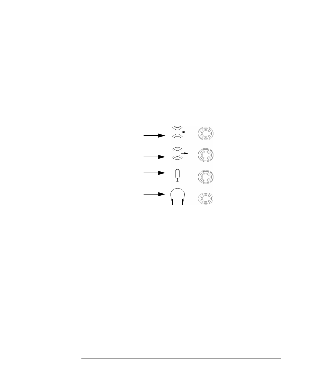
System LCD
The Liquid Crystal Display (LCD) is located on the left side of the front
panel. There are two lines available in this LCD each line being 16
characters wide. The LCD displays messages about the state of the
system, including chassis codes. The symbols in Figure 1-2 appear in the
LCD if you have the HP-UX 10.20 operating system and the Workstation
Additional Core Enhancements for HP-UX 10.20 (June 1999) booted on
your system. They represent the different system activities shown:
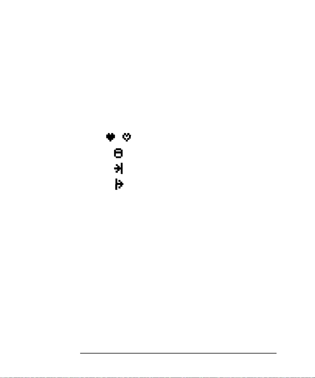
Figure 1-2 LCD Symbols HP VISUALIZE B1000/C3000 Features
Operating system running
Disk access in progress
Network receive in progress
Network transmit in progress
For more information about the Liquid Crystal Display, read the section
“LCD Information” in Chapter 7 of this document.
System Power Switch
The power switch is used to turn the system unit on and off. When you
turn your computer off, the operating system executes an automatic
shutdown -q command. This prevents any damage to programs and
data on your system disk. Turning the power switch back on again
automatically boots up the HP-UX 10.20 operating system and the
Workstation Additional Core Enhancements for HP-UX 10.20 (June
1999) if your system has been configured to auto boot. For information on
setting auto boot, read the section “Setting the Auto Boot and Auto
Search Flags” in Chapter 6 of this document.
26 Chapter1
Page 27

System Overview
System Unit Front Panel and Removable Devices
Removable Media Devices
Depending on your configuration, you can have one or both of the
following removable device drives in your system unit:
• CD drive
• Floppy disk drive
NOTE You cannot have two devices of the same type. For example, you cannot
have two CD drives, and you cannot have two floppy disk drives.
For a more detailed description of each of the removable media device’s
controls, see Chapter 2 for CD drive controls and Chapter 3 for floppy
disk drive controls.
Figure 1-1 shows the system unit with a removable CD drive and a
removable floppy disk drive.
Chapter 1 27
Page 28

System Overview
System Unit Rear Panel Connectors
System Unit Rear Panel Connectors
This section describes the following connectors on the system unit’s rear
panel:
• Audio connectors (including headphones and microphone)
• USB keyboard and mouse connectors
• HP parallel IEEE 1284 I/O connector
• 802.3 TP (Twisted Pair) LAN connector
• RS-232C serial I/O connectors
• SCSI connectors including Ultra2 Wide Low-Voltage Differential and
Ultra Narrow Single-Ended SCSI
• TOC (transfer of control) button
• Power cord connector
NOTE To maintain FCC/EMI compliance, verify that all cables are fully seated
and properly fastened.
28 Chapter1
Page 29
System Overview
System Unit Rear Panel Connectors
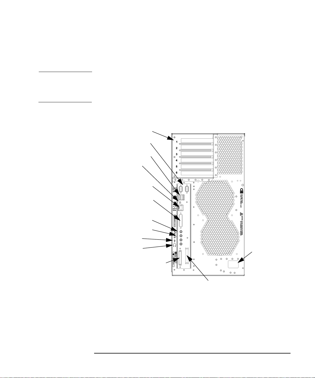
Figure 1-3 shows the locations of the connectors on the system unit’s rear
panel.
NOTE The Ultra Narrow Single-Ended SCSI and Ultra2 Wide Low-Voltage
Differential SCSI connectors must have terminators connected to them
when not in use.
Figure 1-3 System Unit Rear Panel Connectors
Six I/O Card Slots
Two Serial Inputs
Two USB Inputs
TOC Button
LAN Connector
Parallel Connector
Line Input Jack
Line Output Jack
Microphone
Headphones
Ultra2 Wide LVD SCSI
Connector
(Connect Terminator)
Ultra Narrow Single-Ended SCSI
Connector (Connect Terminator)
Power Input
Chapter 1 29
Page 30
System Overview
System Unit Rear Panel Connectors
Audio Connectors
Your computer has audio input and output capability through external
input and output connectors on the rear panel and through an internal
speaker. The rear panel contains the Line IN, Line OUT, Mic IN, and
Headphone OUT connectors. See Figure 1-4.
Figure 1-4 Audio Connectors
Line Input Jack
Line Output Jack
Microphone Jack
Headphone Jack
The audio connectors are standard stereo audio mini-jacks.
Hewlett-Packard recommends using gold-plated plugs available through
audio retailers for best quality recording and playback through the
external connectors. A summary of the computer audio electrical
specifications follows.
30 Chapter1
Page 31

Table 1-2 Audio Electrical Specifications
Frequency Response 25Hz to 20kHz
Max Input Sensitivity/Impedance
System Overview
System Unit Rear Panel Connectors
Line in
Microphone
Max Output Level/Impedance
Line out
Headphone
Speaker (internal)
2.8Vp-p/10Kohm
40mVp-p/47Kohm
2.8Vp-p/920ohm
5.6Vp-p/110ohm
n.a.
USB Connectors
There are two Universal Serial Bus (USB) connectors located on the rear
panel of the computer. These USB connectors support only the HP
keyboard, scroll mouse and hub. You can connect the HP keyboard, scroll
mouse and hub in either of the USB connectors.
The mouse and keyboard were shipped with your system unit, and the
HP hub can be ordered separately. Note that you should consult the
documentation that accompanies each input device for specific
information concerning its use.
For more information on the Universal Serial Bus, use your browser and
the following URL:
http://www.usb.org
Keyboard
The USB connector provides an interface for the keyboard to the system.
This keyboard provides the standard keycaps found on most PC
keyboards.
Chapter 1 31
Page 32

System Overview
System Unit Rear Panel Connectors
HP Scroll Mouse
The HP scroll mouse (USB) has a left and right button that function the
same as most mice. However, it also has a scroll wheel located between
the two buttons that allows for vertical scrolling in a window. Note that
vertical scrolling will only occur if you are in a window’s vertical scroll
bar. This scroll wheel also functions as a middle button when you press
down on it. Essentially, the HP scroll mouse is a three-button mouse.
For general information on the various cursor shapes associated with
different areas of HP CDE while using a mouse, see the Using Your HP
Workstation document.
HP Hub for USB Devices
The HP USB hub provides you with the ability to connect more than one
USB device to your computer, as well as with the ability to extend your
USB device’s cable length. As an example, you may desire to locate your
computer’s keyboard and mouse at a greater distance from your
computer, but your keyboard and mouse cables are not long enough. To
increase the cable length of your keyboard and mouse, you make use of
the USB hub’s extra cable length and connect the hub’s cable to one of
the two connectors on the back of your computer. You then connect the
keyboard and mouse into their separate connectors on the USB hub.
HP Parallel I/O Connector
The 25-pin HP parallel I/O interface uses IEEE 1284 I/O interface
protocols.
802.3 Network Connectors
Your computer has a built-in Twisted Pair (TP) connector for the 802.3
(ETHERNET) or 10 BaseT/100 BaseT network. Your computer will
automatically select the correct network setting.
32 Chapter1
Page 33

RS-232C Serial Input/Output Connector
You can attach a variety of pointing devices (such as a mouse or
trackball), or peripheral devices (such as printers, plotters, modems, and
scanners) to the RS-232C Serial Input/Output (SIO) ports on this
computer. Consult the documentation that accompanies each pointing or
peripheral device for specific information concerning its use.
The SIO ports are programmable. This means that you can set functions
such as bit rate, character length, parity and stop bits using the System
Administration Manager (SAM) or by selecting a system special device
file with the functions already programmed. The SIO ports are used as
an interface for serial asynchronous devices to the CPU.
Table 1-3 shows the SIO connector pin listings. The serial connectors are
9-pin D-sub connectors. Signal names are those specified in the EIA
RS-232 standard.
Table 1-3 Serial I/O Pins
Pin No. Signal Description
System Overview
System Unit Rear Panel Connectors
1 DCD Data Carrier Detect
2 RXD Receive Data
3 TXD Transmit Data
4 DTR Data Terminal Ready
5 GND Ground
6 DSR Data Set Ready
7 RTS Request To Send
8 CTS Clear To Send
9 RI Ring Indicator
Chapter 1 33
Page 34

System Overview
System Unit Rear Panel Connectors
SCSI Connectors
Use the SCSI connectors to connect external SCSI devices such as
DDS-format tape drives. Consult the documentation that accompanies
each SCSI device for specific information concerning its use. Refer to the
chapter “SCSI Connections” for information about connecting SCSI
devices to your computer.
NOTE When attaching external Ultra Narrow Single-Ended SCSI (NSE SCSI)
and Ultra2 Wide Low-Voltage Differential SCSI (LVD SCSI) devices, be
sure to terminate the last device on the external SCSI bus with a
terminator appropriate for that bus. Note that terminators for the LVD
SCSI bus and the NSE SCSI bus are shipped with your product.
Power Cord Connector
Plug the workstation’s power cord into the power cord connector to
provide AC power to the system.
34 Chapter1
Page 35

Security Loop
On the back panel of your HP VISUALIZE B1000/C3000 computer, you will
find a device called a security loop. This device allows you to secure the
internal parts of your computer by providing a means for locking the
computer’s left-side panel. Figure 1-5 provides a view of the security loop
components.
Figure 1-5 Security Loop Components
Security Loop Pin Pushed
In Place By The Padlock
System Overview
Security Loop
Security
Loop Pin
Hole
Security Loop Pin
and Spring
Chapter 1 35
Page 36

System Overview
Security Loop
Locking Your System Unit’s Left-Side Panel
To lock your system unit’s left side panel, follow these steps:
1. Make sure the system unit’s left side panel is closed. See Figure 1-6.
Figure 1-6 Closed Left-Side Panel
System Unit’s
Front Panel
Left Side Panel
(using the front
panel as
reference)
2. Push the security loop’s pin into the security loop pin hole, and insert
the padlock’s latch through the holes at the top and bottom of the
security loop. This locks the left side panel.
3. Lock the padlock. Your system unit’s left side panel is now secure.
36 Chapter1
Page 37

System Overview
Memory
Memory
The main memory for an HP VISUALIZE B1000/C3000 computer can vary
from a minimum of 128 MBytes to a maximum of 2 GBytes. This
computer has eight memory card slots. Note that you can install only 128
MByte and 256 MByte DIMM cards in these slots.
To install DIMM cards in your computer, follow the procedure in the
section “Installing Additional Memory” in the chapter “Changing Your
Computer Hardware Configuration.” Please keep in mind that if memory
is installed improperly or it is bad your computer’s operating system will
not boot-up, and a DIMM error will appear in your computers LCD. If a
DIMM error does occur, please read the section “Memory Failures” in the
chapter “Solving Problems.”
Chapter 1 37
Page 38

System Overview
Monitors
Monitors
You can use one of the following HP monitors with your computer:
• 19-inch, 1280×1024 color, 75Hz (A4575A)
• 19-inch, 1600×1200 color, 75Hz (A4575A)
• 21-inch, 1280×1024 color (stereo capability), 75Hz (A4576A)
• 21-inch, 1600×1200 color, 75Hz (A4576A)
Before using your monitor, you should become familiar with its controls,
connectors and indicators. For information on these controls and
indicators and on using your monitor, see the documentation that came
with the monitor.
Note that connection to earlier HP monitors with 15-pin mini-DSub
cables can be made using the A4168A adapter cable shipped with your
system miscellaneous kit.
38 Chapter1
Page 39

System Overview
Operating System Overview
Operating System Overview
Your computer uses the HP-UX 10.20 operating system and the
Workstation Additional Core Enhancements for HP-UX 10.20 (June
1999). Instant ignition systems (systems with preloaded software) have
X-Windows, Hewlett-Packard’s graphical user interface, and HP CDE
installed and configured.
Please refer to the “Instant Ignition System Information” sheet that
came with your system for details on configuration.
If your Instant Ignition system does not have the kernel preconfigured
with all of the device drivers, you need to refer to the manual Managing
Systems and Workgroups to configure your kernel.
If you have any questions about Instant Ignition, refer to Using Your HP
Workstation for more information.
Note that both of the documents mentioned in the previous paragraphs
can be found on the world-wide web at the following Uniform Resource
Locator (URL):
http://www.docs.hp.com/
Chapter 1 39
Page 40

System Overview
Information You Need to Record
Information You Need to Record
Before you begin using your computer, take a moment to gather the
following important information and record it in the appropriate
subsection for future use:
• LAN Station ID
• Internet Protocol (IP) address
• Subnetwork mask
LAN Station ID
Locate the contents label that came with your computer shipping carton.
Find the LAN Station ID listed there and record it here:
LAN Station ID:__________________________________________________
The LAN Station ID can also be found on the back of the computer near
the LAN connector. If the previous methods for locating your LAN
Station ID do not work, you can get your LAN Station ID by executing
the lanscan command in a terminal window.
IP Address and Subnetwork Mask Information
Get the IP address and the subnet mask information for your computer
from either your system administrator or your network administrator
and note them here:
IP Address: ______________________________________________________
Subnet Mask: ____________________________________________________
40 Chapter1
Page 41

System Overview
Powering Up Your System
Powering Up Your System
After you have connected the various parts of the computer—for details,
see the B1000/C3000 Installation Sheet that came with your
computer—you are ready to power up the system. At this point, there are
two possibilities:
• Your computer has been “ignited;” that is, the HP’s Instant Ignition
process has installed the operating system already. In this case, when
you power up the computer, you will be presented with a series of
questions asking you the machine’s host name, IP address, subnet
mask, and other basic configuration questions (see the section
“Getting Required Information”). When these are answered, the CDE
login screen will appear.
• Your computer has not been “ignited;” that is, the HP’s Instant
Ignition process has not installed the operating system already. In
this case, you will need to install the operating system from the CDs
found in the HP-UX 10.20 Software for Workstations ACE media kit;
for details, see the CD Booklet included with the CDs. Note that the
CDs contain the HP-UX 10.20 operating system, as well as the June
1999 HP-UX 10.20 ACE bundles. The ACE bundles reside on the IPR
media, and are also available from the following URL:
http://www.software.hp.com/ACE
When the operating system (HP-UX 10.20) and the HP-UX 10.20
ACE (June 1998) are both installed, you will need to answer the
questions noted above for the ignited system. After the questions
have been answered, the CDE login screen will appear.
Once the CDE login screen appears, and you can log in as
root—initially, there is no password. When you have logged in, you will
be able to create other users’ accounts and do whatever other
configuration and installations you require to get the machine into its
desired state. See the HP CDE Getting Started Guide and the User’s
Guide for instructions on typical tasks.
Chapter 1 41
Page 42

System Overview
Powering Up Your System
Getting Required Information
The start-up procedure for your workstation will require you to supply
the following information. Therefore, you should find out this
information before you turn the workstation on for the first time.
NOTE If you are not the system administrator for your workstation, and you do
not know the required information, ask your system administrator for
the information.
Here is the information you will need. Please take time to fill in the
blanks.
• Host name _____________________________________________
The host name is sometimes called the “system name.”
• Internet Protocol address ________________________________
You will need this address if you are connecting the workstation to a
local area network.
• Time zone ______________________________________________
This is the time zone where the workstation is located.
• Optional networking parameters
Ask your system administrator if you need to configure these
parameters.
Subnetwork mask
Network gateway IP address
Local domain name
DNS server host name
DNS server IP address
Network Information Service domain name
__________________
__________________
__________________
__________________
__________________
__________________
42 Chapter1
Page 43

System Overview
Powering Up Your System
• Optional font server parameters
You need to supply these parameters if you want the workstation to
obtain its fonts on a network server. Ask your system administrator if
you need to configure these parameters.
Font server name
Font server IP address
__________________
__________________
Chapter 1 43
Page 44

System Overview
Powering Up Your System
Turning on the Power
1. Turn on the monitor and any external peripherals (for example,
printers) connected to the workstation.
2. Turn on the workstation. The workstation will run a series of
self-tests.
3. After two or three minutes, a series of messages are displayed as
various hardware and software subsystems are activated. Unless
something is wrong with your system, you are not asked to respond to
these messages.
4. A series of windows appears requesting the information you gathered
in the previous section, such as your host name, IP address, and time
zone. Enter the information as it is requested.
NOTE You should enter the host name when requested; otherwise, you will get
an error message when you log in.
If you do not have other pieces of information, press Enter to use the
default value. You can provide missing information later by logging into
a terminal emulator window as superuser and executing this command:
/sbin/set_parms
5. You are now asked if you want to set a root password. Specify the
root password now. The root password is the password used for the
superuser account. The superuser is a special user who has
permission to perform all system administration tasks. The user
name for the superuser is root.
6. When you have finished answering all of the questions, the
workstation completes its start-up sequence and displays the CDE
login screen.
44 Chapter1
Page 45

System Overview
Powering Up Your System
7. Log into your first CDE session as root. For information on logging
into CDE, see the Common Desktop Environment User’s Guide.
NOTE You must log into the first session as root. This is because the system
contains no other user accounts. Once you have created user accounts,
you should log out as superuser and log back in as one of the other users.
8. Use the System Administration Manager (SAM) to set-up user
accounts.
Documentation
The documentation for your system is located on the “Instant
Information” CD. To view this CD, you need to read the special mounting
instruction that come with it.
Chapter 1 45
Page 46

System Overview
Powering Up Your System
46 Chapter1
Page 47

2 Using Your CD Drive
This chapter provides an overview of the optional CD drive and media as
well as an explanation of how to use the CD drive.
47
Page 48

Using Your CD Drive
Here are the topics covered in this chapter:
• Operating the CD Drive
• Mounting and Unmounting a CD
• Verifying the CD Drive Operation
• Configuring the CD Driver
• Audio Control for the CD Drive
• CD Media Description
The instructions in this chapter assume you are using the HP-UX 10.20
operating system and Workstation Additional Core Enhancements for
HP-UX 10.20 (June 1999) with the HP CDE interface.
For information about installing or removing a CD drive, see Chapter 5
of this document.
NOTE Be sure you have read and understand the information on mounting and
unmounting CDs before you begin using your CD drive.
NOTE This chapter requires you to be superuser (root). If you cannot log in as
root, contact your system administrator.
In this chapter, the terms “CD” and “CD drive” are use rather than
“CD-ROM” and “CD-ROM drive” because the CD drives used in the
B1000 and the C3000 can read the original CD-ROM disks, plus CD-R
disks and the newer CD-RW disks (also called “CD-RAM” because they
are rewritable). Thus, since not all CDs are ROMs any longer, that
portion of the term has been dropped.
Incidentally, the CD drives also are multisession-capable.
48 Chapter2
Page 49

Using Your CD Drive
CD Media Description
CD Media Description
CDs, which can be CD-ROMs, CD-Rs, or CD-RWs, are 120mm (4.7
inches) in diameter, and use one data surface with a capacity of 600
megabytes. The data surface contains pits and flat spots arranged in a
continuous spiral track, which is read at a constant speed. You may
access files and data stored on a CD, but you may not write files or data
to a CD.
CAUTION Handle CDs by the edges only. Always be sure a CD is either in the CD
drive or its protective case when not in use. This will reduce the chance
of exposing the disk surface to dust. Over time, dust reduces the
reliability of the read head in the CD drive.
Caring for CDs
Observe the following guidelines to help prevent data loss and prolong
the life of you CD and CD drive:
• Use CDs in a clean environment to prevent dust particles from
scratching disc surfaces.
• Store CDs in a cool, dry place to prevent moisture and heat damage.
• Do not try to clean the surface of a CD with cleaning solvents, as some
cleaning solvents may damage the disk.
Chapter 2 49
Page 50

Using Your CD Drive
Operating the CD Drive
Operating the CD Drive
This section provides a description of the CD drive and it describes how
to perform tasks with your CD drive.
CD Drive
The CD drive is a mass storage device that can read removable CD-ROM,
CD-R, and CD-WR media. The drive supports the ISO 9660 and High
Sierra format standards. You can access information from the drive like
any other disk drive, except you cannot write to the drive. The drive
contains a semiconductor laser for reading data optically, and includes
an embedded controller with an ATAPI interface.
50 Chapter2
Page 51

Using Your CD Drive
Operating the CD Drive
Controls and Features
Figure 2-1 and Table 2-1 describe the operating controls and features of
the CD drive.
NOTE The exact positioning of CD Drive controls/features may vary depending
on the model of the device.
Figure 2-1 CD Drive Controls and Features
Disk
Tray
Busy Indicator
Table 2-1 CD Drive Operating Controls and Features
Control/Feature Purpose
Busy Indicator The Busy Indicator blinks during a data transfer.
Eject Button The Eject Button when pressed opens the Disk Tray
Emergency Eject You can open the Disk Tray when the computer does
Disk Tray The Disk Tray holds the CD. This style of CD drive
Note that there is neither a volume control nor a headphone jack on the
front of the CD drive. To listen to an audio CD, use the headphone jack
on the rear panel, and control the sound volume via software called
“xmcd” (for details, see “Audio Control for the CD Drive” on page 63).
Emergency Eject
for removal or insertion of a disk. When the drive is in
use, you must press the eject button for more than one
second to open the Disk Tray.
not have power by inserting the end of a paper clip
into this opening.
does not use a disk caddy.
Eject Button
Chapter 2 51
Page 52

Using Your CD Drive
Operating the CD Drive
Loading and Unloading a CD
This section explains how to load or unload a CD.
NOTE To use the file system on a CD, you must be superuser (root) and mount
the disk as discussed in the section “Mounting a CD Using SAM.” Once
the CD has been mounted, you must unmount it before removing the CD.
Unmounting a CD is discussed in the section “Unmounting a CD Using
SAM.”
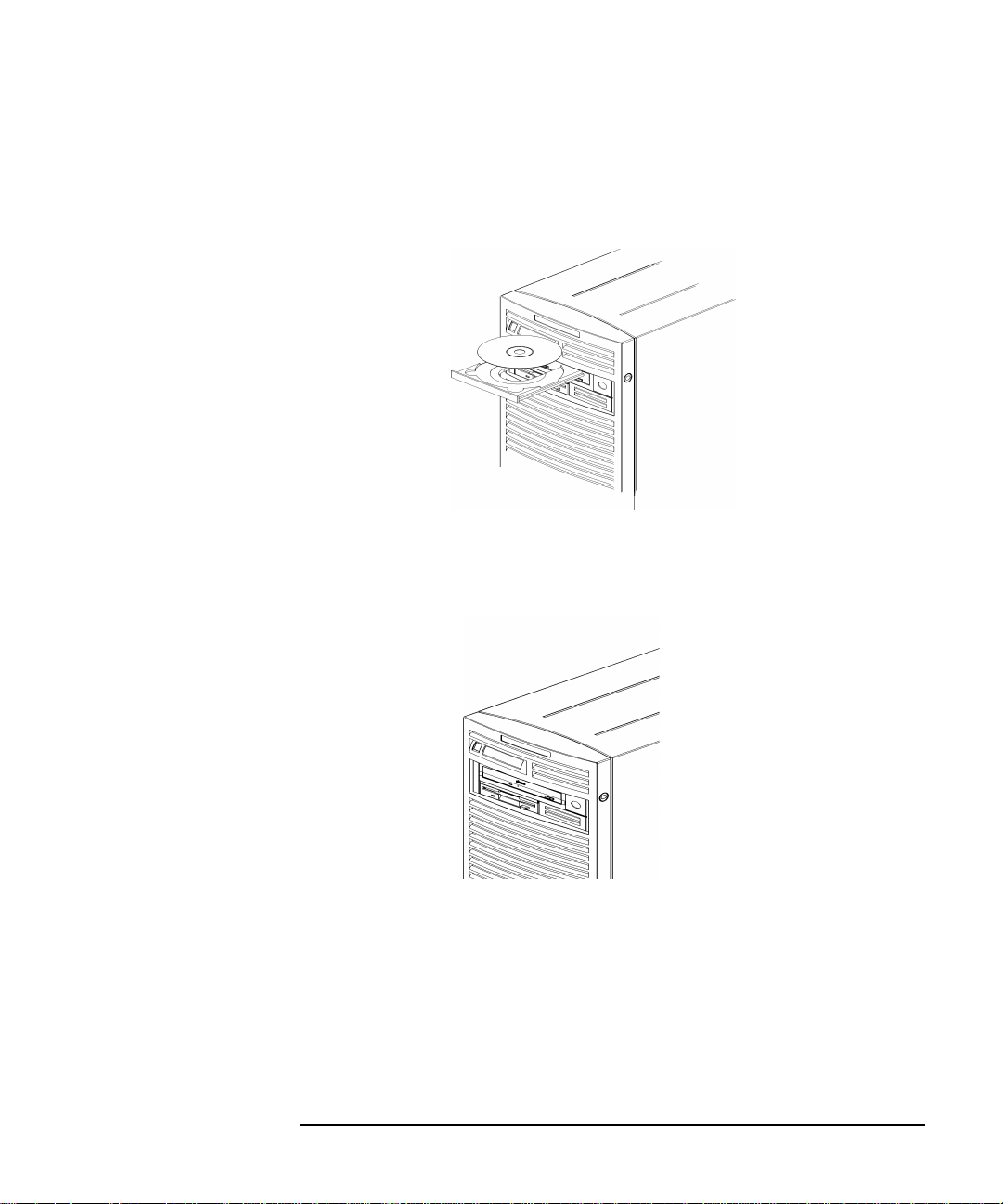
Loading a CD
This CD drive has an automatic loading/ejecting feature. To load a CD in
the CD drive, follow these steps:
1. Press and release the eject button on the CD drive. The disk tray
opens as shown in Figure 2-2.
Figure 2-2 Open CD Tray
52 Chapter2
Page 53
2. Hold the disk by the edges with the label side up and place it in the
disk tray as shown in Figure 2-3.
Figure 2-3 Placing the CD in the Disk Tray
3. Press the eject button to close the tray as shown in Figure 2-4.
Figure 2-4 Closed Disk Tray
Using Your CD Drive
Operating the CD Drive
Chapter 2 53
Page 54

Using Your CD Drive
Operating the CD Drive
Unloading a CD
To unload a disk from the Disk Tray, follow these steps:
1. Press and release the eject button on the CD drive to open the disk
tray.
2. Grasp the disk by the edges and lift it out of the disk tray.
3. Press the Eject Button to close the disk tray.
Locating Help
If you have trouble with any of the procedures for using your CD drive,
see the chapter “Solving Problems” in this document.
54 Chapter2
Page 55

Using Your CD Drive
Mounting and Unmounting a CD
Mounting and Unmounting a CD
This section of the chapter explains how to mount and unmount a CD
using the System Administration Manager (SAM).
The procedures in this section require you to log in as root. If you cannot
log in as root, contact you system administrator.
Mounting a CD Using SAM
To access your CD drive, you must mount a CD every time you insert it
into the drive. This applies to CDs with file system information only. If
you wish to load a music CD, for example, you would not need to mount
the disk. Mounting a disk with file system information gives the disk a
path name that allows your computer to communicate with it. You must
unmount the CD before removing it from the drive.
To mount a CD on an HP-UX 10.20 operating system with the
Workstation Additional Core Enhancements for HP-UX 10.20 (June
1999), perform the steps covered in this section.
1. Log in as root.
2. Move the mouse pointer to the Application Manager control for
tools and click the left mouse button. Alternatively you can execute
sam at a terminal window command prompt and skip to step 5.
Chapter 2 55
Page 56

Using Your CD Drive
Mounting and Unmounting a CD
3. Double click on the System_Admin icon in the Application
Manager window.
4. Double click on the Sam icon in the Application Manager -System_Admin window. If you are root, the System Application
Manager (SAM) will appear on your screen.
5. Double click on the Disk and File System icon.
56 Chapter2
Page 57

Using Your CD Drive
Mounting and Unmounting a CD
6. Double click on the Disk Devices icon.
The following screen message is displayed:
Scanning the system’s hardware...
The Disk and File Systems window opens containing a list of
devices installed in this system. From the list of devices, choose the
CD drive you would like to configure as a file system by clicking on
the device to highlight it.
7. Click on Add in the Actions menu. For this example you will select
the item Not Using the Logical Volume Manager. However, you
can select any appropriate item from the Actions menu.
8. Enter the mount directory name (for example, /disk1) in the Mount
Directory field of the Add Disk without LVM window.
9. Click on the Modify Defaults... button. In the Modify Defaults
window, select the Read Only item from the Access button menu.
Next, unselect the Create New File System item by clicking on it.
Exit the Modify Defaults window by clicking on the OK button.
10.Click on the OK button in the Add Disk without LVM window. You
will need to wait for a short time for the CD to be mounted. When the
Add Disk without LVM window disappears and CDFS appears in
the Use column of the Disk and File Systems window, you have
mounted the CD.
Chapter 2 57
Page 58

Using Your CD Drive
Mounting and Unmounting a CD
Unmounting a CD Using SAM
You must unmount a CD before it will eject from the drive.
NOTE Before you unmount a CD, make sure that your working directory is set
to a directory other than the one under which the disk was mounted.
To unmount a CD on an HP-UX 10.20 operating system with the
Workstation Additional Core Enhancements for HP-UX 10.20 (June
1999), perform the steps covered in this section.
1. Log in as root.
2. Move the mouse pointer to the Application Manager control for
tools and click the left mouse button. Alternatively you can execute
sam at a terminal window command prompt and skip to step 5.
3. Double click on the System_Admin icon in the Application
Manager window.
58 Chapter2
Page 59

Using Your CD Drive
Mounting and Unmounting a CD
4. Double click on the Sam icon in the Application Manager -System_Admin window. If you are root, the System Application
Manager (SAM) will appear on your screen.
5. Double click on the Disk and File System icon.
6. Double click on the Disk Devices icon.
The following screen message is displayed:
Scanning the system’s hardware...
The Disk and File Systems window opens containing a list of
devices installed in this system. From the list of devices, choose the
CD drive you would like to remove (unmount) by highlighting that
device.
Chapter 2 59
Page 60

Using Your CD Drive
Mounting and Unmounting a CD
7. Click on Remove in the Actions menu. In the window that next
appears, click on the Yes button. This will unmount the CD. You will
need to wait for a short time before the CD is unmounted. The CD is
successfully unmounted when you see Unused in the Use column of
the Add Disk without LVM window.
60 Chapter2
Page 61

Using Your CD Drive
Verifying the CD Drive Operation
Verifying the CD Drive Operation
To verify that your workstation can communicate with the CD drive,
follow the steps covered in this section. Note that to perform the steps
required in this section, you must be superuser (root). If you cannot log
in as root contact your system administrator.
1. Log in as root.
2. Type the following command at the shell prompt and press Enter:
/usr/sbin/ioscan -d sdisk
After a few seconds the ioscan utility lists all of the I/O devices that
use the “sdisk” driver. Your CD drive should be among the devices
listed. The list appears similar to the following:
H/W Path Class Description
===============================================
10/0/15/1.5.0 disk SEAGATE ST39102LC
10/0/15/1.6.0 disk SEAGATE ST39102LC
10/0/14/0.0.0 disk TEAC CD-532E-B
If ioscan does not detect any usable I/O system devices, such as the
CD drive, nothing is output and you are returned to the system
prompt. Since this indicates possibly that the driver for the CD drive
is not configured, read the section “Configuring the CD Driver” in this
chapter.
Chapter 2 61
Page 62

Using Your CD Drive
Configuring the CD Driver
Configuring the CD Driver
If you reload software or rebuild the Instant Ignition system on your
computer, you may need to reconfigure the HP-UX kernel to add the CD
driver. Use the SAM utility to add the CD driver and build a new HP-UX
kernel.
For more information about how to reconfigure the kernel using SAM,
see the following manuals:
• Managing Systems and Workgroups
• Using HP-UX
62 Chapter2
Page 63

Using Your CD Drive
Audio Control for the CD Drive
Audio Control for the CD Drive
In order to control the playing of audio CDs on your CD drive, you will
need a third party “CD player” application. One such application that
supports HP workstations is xmcd. This is a third-party “CD player”
utility that runs on an X window system using the Motif graphical user
interface. The xmcd utility is not supported by Hewlett-Packard. Since
the xmcd utility is not a part of HP-UX, you will need to download it off
the web using your web browser and this URL:
http://metalab.unc.edu/tkan/xmcd
Installing the xmcd Utility
Here is the procedure for downloading the xmcd utility to your system:
1. Log in as root.
2. Type the previously given URL into the entry box on your web
browser and press Enter.
3. Select the menu item labeled Downloads found on the xmcd
homepage.
4. Scroll down to the section “Select your platform:” on the Downloads
web page and select the item labeled “HP-UX 9.x and later (HP
PA-RISC).”
5. Wait for a few seconds for the Save As... pop-up window to appear. In
this window, click in the Selection entry box and type the following
path and file name:
/tmp/xmcdbin.tar.gz
Next, click the OK button. This completes the download of xmcd to
your system.
6. Follow the instructions in the section “Instructions to unpack xmcd
binary” found on this Binary Downloads web page. This will
complete the installation of the xmcd utility.
Chapter 2 63
Page 64

Using Your CD Drive
Audio Control for the CD Drive
Using the xmcd Utility
The instructions in the section assume that you are using the HP-UX
10.20 operating system and the Workstation Additional Core
Enhancements (ACE) for HP-UX 10.20 (June 1999) with the HP CDE
interface. The xmcd utility must also be installed on your system. See the
section “Installing the xmcd Utility.”
To load and play an audio CD, follow the steps in this procedure.
1. Load the audio CD. See the section “Loading a CD” in this chapter.
2. Insert the headphone plug into the headphone jack located on the
back of your system unit.
Line Input Jack
Line Output Jack
Microphone Jack
Headphone Jack
3. Click on the Audio icon located on your HP CDE control panel.
Audio Icon
64 Chapter2
Page 65

Using Your CD Drive
Audio Control for the CD Drive
4. Click on the Monitoring checkbox in the Audio window to select it.
Then select the Output menu and click on the Headphones item in
the menu list. In the File menu select the item Close, this will close
the Audio window and save your settings. Note that the Output
Volume slider in the Audio window does not control the CD drive’s
volume level. To control the CD drive’s volume, you need to use the
volume slider on the xmcd user interface. See the window in step 5.
5. Start the utility by typing xmcd at the prompt and pressing Enter.
Play/Pause
Button
Eject
Button
Help Button
Now that you have your audio CD player started, put on your
headphones and press the Play button to listen to the audio CD. Note
that pressing the Help button will give you information on how to use
the rest of the CD player’s buttons.
Chapter 2 65
Volume Slider
Keypad
Stop
Button
Page 66

Using Your CD Drive
Audio Control for the CD Drive
66 Chapter2
Page 67

3 Using Your 3.5-Inch Floppy Disk
Drive
This chapter describes how to perform tasks that allow you to archive to
or transfer data from the 3.5-inch floppy disk drive.
67
Page 68

Using Your 3.5-Inch Floppy Disk Drive
The instructions in this chapter assume you are using the HP-UX 10.20
operating system and the Workstation Additional Core Enhancements
for HP-UX 10.20 (June 1999) with the HP CDE interface.
NOTE When examples of user input are given in this chapter, enter them at the
command-line prompt in an HP CDE terminal window.
Some procedures in this chapter require you to log in as superuser
(root). If you cannot log in as root, contact your system administrator.
Here are the topics covered in this chapter:
• Operating the Floppy Drive
• Verifying the Floppy Drive Configuration
• Additional Floppy Drive Information.
For information on installing and removing a floppy disk drive, see
Chapter 5 of this document.
68 Chapter3
Page 69
Using Your 3.5-Inch Floppy Disk Drive
Operating the Floppy Drive
This section describes how to perform tasks with your 3.5-inch floppy
disk drive.
Floppy Disk Drive
The floppy disk drive is a random access read/write mass storage device
that uses removable floppy diskettes. The drive supports the 1.44 Mbyte
High Density standard. You can access information from the drive like
any other disk drive, that is you can write information to it and read
information from it.
Controls and Features
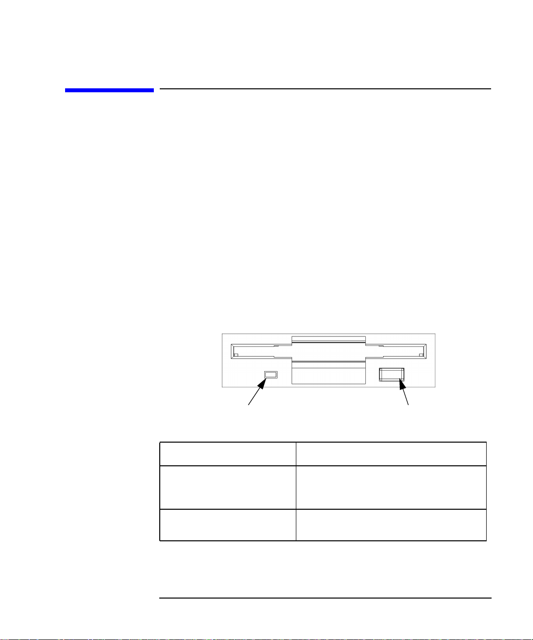
Figure 3-1 and Table 3-1 describe the operating controls and features of
the floppy disk drive.
Figure 3-1 Floppy Disk Drive Controls and Features
Operating the Floppy Drive
Eject ButtonBusy Indicator
Table 3-1 Floppy Disk Drive Operating Controls and Features
Control/Feature Purpose
Busy Indicator The Busy Indicator illuminates during a data
access operation and blinks during a data
transfer.
Eject Button The Eject Button, when pressed, ejects the
floppy diskette from the floppy disk drive.
Chapter 3 69
Page 70

Using Your 3.5-Inch Floppy Disk Drive
Operating the Floppy Drive
Using the Floppy Diskette
This section describes basic information needed to use your floppy
diskettes.
Setting the Write-Protect Tab on a Diskette
You can only store or change information on a diskette when the
write-protect tab is in the write position. So, before trying to write to the
diskette, make sure that the write-protect tab is in the write position, as
shown in Figure 3-2.
Figure 3-2 Setting the Write-Protect Tab on a Floppy Diskette
Write-Protect Tab
Slide tab up for
write-protect
Slide tab down to
write
To protect files on a diskette from being overwritten, set the
write-protect tab to the write-protect position.
NOTE The write-protect tab should always be in the write position for
formatting a new diskette and transferring data to a diskette.
70 Chapter3
Page 71

Using Your 3.5-Inch Floppy Disk Drive
Operating the Floppy Drive
Inserting and Removing a Diskette
Follow these steps to insert and remove a diskette from the floppy disk
drive.
1. Insert the diskette into the drive, as shown in Figure 3-3.
Figure 3-3 Inserting and Removing a Floppy Diskette
2. Push the diskette into the floppy drive until it clicks into place.
3. Remove the diskette by pressing the eject button (see Figure 3-1) and
taking it out of the drive.
Using Device Files
Device files are special files that tell your system which pathway through
the system hardware to use when communicating with a specific device.
Device files also describe the type of device. You will need to know the
special device file associated with your floppy disk drive so that you can
write data to it or read data from it.
NOTE The device file names depend on the naming conventions of your
particular system.
Chapter 3 71
Page 72

Using Your 3.5-Inch Floppy Disk Drive
Operating the Floppy Drive
To determine what device files are available for use with your floppy
drive, use the following procedure:
1. Log in as root.
2. Move the mouse pointer to the Application Manager control for
tools and click the left mouse button. Alternatively you can execute
sam at a terminal window command prompt and skip to step 5.
3. Double click on the System_Admin icon in the Application
Manager window.
72 Chapter3
Page 73

Using Your 3.5-Inch Floppy Disk Drive
Operating the Floppy Drive
4. Double click on the Sam icon in the Application Manager -System_Admin window. If you are root, the System Application
Manager (SAM) will appear on your screen.
5. Double click on the Disk and File System icon.
6. Double click on the Disk Devices icon.
The following screen message is displayed:
Scanning the system’s hardware...
The Disk and File Systems window opens containing a list of
devices installed in this system. From the list of devices, choose the
floppy disk drive you would like to configure as a file system by
clicking on the device to highlight it.
7. Select the Actions menu and then select the menu item View More
Information. A window opens with a list of information for the
floppy drive, including the device files.
Chapter 3 73
Page 74

Using Your 3.5-Inch Floppy Disk Drive
Operating the Floppy Drive
Formatting a New Diskette
If you have floppy diskettes that have been previously formatted using
the mediainit utility, you can skip this section. Otherwise, you must
always format a new floppy diskette with the mediainit utility before
using the diskette. To format a new floppy diskette, follow these steps:
1. Log in as root.
2. Make sure that the write-protect tab on the floppy diskette is in the
write position, as shown in Figure 3-2.
3. Insert the diskette into the floppy disk drive.
4. Type the following at the prompt and press Enter:
mediainit -f 16
where 16 is the High Density (HD) format option and
the device file as listed by SAM. See the section “Using Device Files”
in this chapter. For a listing of format options, see the floppy manual
page. To view this manual page, type the following at the prompt and
press Enter:
man floppy
devicefile
devicefile
is
74 Chapter3
Page 75

Using Your 3.5-Inch Floppy Disk Drive
Operating the Floppy Drive
Transferring Data To and From a Floppy Diskette
This section describes how to transfer data (reading and writing) to and
from your floppy diskette using the HP-UX tar command with your
floppy drive’s device file.
You need to set the write-protect tab to the write position to transfer data
to the diskette. The write-protect tab can be in either position when
restoring data from a diskette or listing the files on a diskette.
Saving Files to a Floppy Diskette
Use the following instructions to save files to a floppy diskette:
1. Check the write-protect tab on the floppy diskette to ensure that it is
in the write position.
2. Load the formatted floppy diskette into the disk drive.
3. Type the following command in a terminal window at the prompt and
press Enter:
tar -cvf
where
“Using Device Files” in this chapter), and
of the file or directory containing files that you want to write to the
diskette.
Chapter 3 75
devicefile
devicefile pathname
is the device file as listed by SAM (see the section
pathname
is the path name
Page 76

Using Your 3.5-Inch Floppy Disk Drive
Operating the Floppy Drive
Restoring Files from a Floppy Diskette to Your System
Use the following instructions to restore files from a floppy diskette to
your system:
1. Load the floppy diskette into the disk drive.
2. Type the following command in a terminal window at the prompt and
press Enter:
cd
directory_path
This command changes you to the directory in which you want the
files to reside.
3. Enter the following command at the prompt and press Enter:
tar -xvf
where
“Using Device Files” in this chapter) and
of the file or directory containing files that you want to restore from
the diskette. If you do not specify
diskette is restored.
devicefile
devicefile pathname
is the device file as listed in SAM (see the section
pathname
pathname
, everything on the floppy
is the path name
Listing the Files on a Floppy Diskette
Use the following instructions to list the files on a floppy diskette:
1. Load the floppy diskette into the disk drive.
2. Enter the following command in a terminal window at the prompt
and press Enter:
tar -tvf
where
section “Using Device Files” in this chapter. Note that this command
will list all files on the floppy diskette.
devicefile
devicefile
is the device file as listed by SAM. See the
Troubleshooting
If you have trouble with any of the procedures for using your floppy disk
drive, see Chapter 7 of this document, “Solving Problems.”
76 Chapter3
Page 77

Using Your 3.5-Inch Floppy Disk Drive
Verifying the Floppy Drive Configuration
Verifying the Floppy Drive Configuration
To verify that your workstation can communicate with the floppy drive,
use the ioscan command in a terminal window to see which devices are
currently in use on your system. Note that you will have to be superuser
or root to use the ioscan command.
Enter the following command at the prompt and press Enter:
/usr/sbin/ioscan -fnC floppy
After a few seconds, the ioscan utility lists all of the I/O devices that
use the “floppy” class. Your floppy drive should be among the devices
listed. The list appears similar to the following:
Class I H/W Path Driver S/W State H/W Type Description
========================================================================
floppy 0 10/0/14/1/4.1 sioflop CLAIMED DEVICE HP_PC_FDC_FLOPPY
/dev/floppy/c0t1d0 /dev/rfloppy/c0t1d0
If ioscan does not detect any usable I/O system devices that use the
“floppy” class, such as the floppy disk drive, nothing is output and you
are returned to the system prompt. If this is the case, refer to Chapter 7,
“Solving Problems.”
If the floppy disk driver is not configured, ioscan returns the following
message:
ioscan: Device driver floppy is not in the kernel
If you receive this message, go to the section, “Configuring the Floppy
Driver” in this chapter for information on adding the sioflop driver to
the HP-UX kernel configuration.
Chapter 3 77
Page 78

Using Your 3.5-Inch Floppy Disk Drive
Additional Floppy Drive Information
Additional Floppy Drive Information
This section provides information about configuration of the floppy disk
driver and information about useful HP-UX commands for copying and
listing floppy disk files.
Configuring the Floppy Driver
If you reload software or rebuild the Instant Ignition system on your
computer, you may need to reconfigure the HP-UX kernel to add the
floppy disk driver. Use the SAM utility to add the sioflop disk driver
and build a new HP-UX kernel.
For more information about how to reconfigure the kernel using SAM,
see the following manuals:
• Managing Systems and Workgroups
• Using HP-UX
For More Information
For more information on using tar and a complete list of the command
arguments, refer to the tar man page by typing the following command
in a terminal window at the prompt and pressing Enter:
man tar
You can mount the floppy drive as a file system using the SAM utility. Be
sure to unmount the drive before removing it as a file system. For more
information about how to mount and unmount the floppy drive, see the
manual Using HP-UX.
For more information on copying data to or from your system to other
media, including your floppy diskette, refer to the cpio man page by
typing the following command in a terminal window at the prompt and
pressing Enter:
man cpio
78 Chapter3
Page 79

Using Your 3.5-Inch Floppy Disk Drive
Additional Floppy Drive Information
For more information on copying to or from DOS files, refer to the doscp
man page by typing the following command in a terminal window at the
prompt and pressing Enter:
man doscp
For more information on listing DOS directories, refer to the dosls man
page by typing the following command in a terminal window at the
prompt and pressing Enter:
man dosls
For more information on using your floppy disk drive and floppy
diskettes, refer to the floppy man page by typing the following
command in a terminal window at the prompt and pressing Enter:
man floppy
For more information on using the mediainit command, refer to the
mediainit man page by typing the following command in a terminal
window at the prompt and pressing Enter:
man mediainit
Chapter 3 79
Page 80

Using Your 3.5-Inch Floppy Disk Drive
Additional Floppy Drive Information
80 Chapter3
Page 81

4 SCSI Connections
This chapter provides information about connecting Small Computer
System Interface (SCSI) devices to an HP VISUALIZE B1000/C3000
computer.
81
Page 82

SCSI Connections
Here are the topics covered in this section:
• SCSI bus differences
• SCSI Restrictions
• Determining SCSI Bus Length
• Assigning SCSI Device IDs
• Connecting to the SCSI Ports
The instructions in this chapter assume you are using the HP-UX 10.20
operating system and the Workstation Additional Core Enhancements
for HP-UX 10.20 (June 1999) with HP CDE.
NOTE When attaching external SCSI devices, be sure to terminate the last
device on the external SCSI bus. Note that these terminators were
shipped with your system.
82 Chapter4
Page 83

SCSI Connections
SCSI Bus Differences
SCSI Bus Differences
A Small Computer Systems Interface (SCSI) bus is an IEEE standard
bus for connecting your workstation to internal and external devices
(SCSI devices) running at different speeds. There may be one device
connected to the external SCSI port or several SCSI devices may be daisy
chained together and connected to the external SCSI port. Examples of
these SCSI devices are 4-mm DDS-format tape drives and hard disk
drives.
There are two types of SCSI buses available with this workstation—an
Ultra Narrow Single-Ended SCSI bus (NSE SCSI), and an Ultra2 Wide
Low-Voltage Differential SCSI bus (LVD SCSI). The following table
shows the specification differences between these SCSI buses.
CAUTION Currently Hewlett-Packard does not support mixing Ultra Narrow
Single-Ended and Ultra2 Wide Low-Voltage Differential devices on any
one bus type.
Table 4-1 SCSI Bus Differences
Type Data
Transfer
Rate
Ultra Narrow
Single-Ended
Ultra2 Wide
Low-Voltage
Differential
1. Address 7 is reserved for host controller use on all buses.
2. This information is specific to the HP VISUALIZE B1000/C3000 computer.
Up to 20
Mbytes/sec
Up to 80
Mbytes/sec
Chapter 4 83
Data Bus
Width
8 bits 0 through 6 3.0 meters
16 bits 0 through 6; 8
Available
SCSI
Addresses
through 15
1
Maximum
Cable Length
(9.84 feet)
12 meters
(39.37 feet)
Device
Physical
Location
External
Internal and
external
2
Page 84

SCSI Connections
SCSI Restrictions
SCSI Restrictions
This section describes the SCSI restrictions that apply to your
workstation in the following areas:
• Cables
• Terminators
• Number of Devices Per SCSI Bus
• Considerations for Selecting SCSI Devices
Note that the narrow single-ended SCSI bus supports only 7 devices
because address 7 is reserved by the system. The Ultra2 Wide
Low-Voltage Differential SCSI bus supports only 15 devices because
address 7 is reserved by the system.
Cables
Only SCSI cables approved by HP can be used to connect your
workstation to any SCSI devices. HP offers the following SCSI cables for
Ultra Narrow Single-Ended SCSI devices:
Table 4-2 Ultra Narrow Single-Ended SCSI Cables
Cable
Number
C2955A 0.5m
C2908A 1.0m
C2956A 1.5m
C2957A 2.0m
1. High Density Thumb Screw (HDTS)
84 Chapter4
Cable
Length
50-pin HDTS1 to 50-pin HDTS
Description
Page 85

HP offers the following SCSI cables for connecting externally connected
devices to the system Ultra2 Wide Low-Voltage Differential port:
Table 4-3 Ultra2 Wide Low-Voltage Differential SCSI Cables
SCSI Connections
SCSI Restrictions
Cable
Number
C2978A 0.5m
C2979A 1.5m
C2911B 1.0m
C2924B 2.5m
C2361A 1.0m
C2362A 2.5m
C2363A 10.0m
C2365A 5.0m
1. High Density Thumbscrew (HDTS)
2. Very High Density Cabled Interconnect (VHDCI)
CAUTION SCSI cables approved by HP are designed to function within the SCSI
tolerances for HP devices. Use of other cables can result in significant
problems with system operation.
Cable
Length
Description
68-pin HDTS1 to 68-pin HDTS
68-pin VHDCI2 to 68-pin HDTS
Always use the shortest possible cable(s) for your configuration.
NOTE See “SCSI Bus Length Constraints” later in this chapter to determine
the total length of your cables.
Chapter 4 85
Page 86

SCSI Connections
SCSI Restrictions
Terminators
The terminators for Ultra2 Wide Low-Voltage Differential SCSI (LVD
SCSI) and Ultra Narrow Single-Ended SCSI (NSE SCSI) are different.
The NSE SCSI terminator has 50 pins and will fit on a NSE SCSI
connector. The LVD SCSI terminator has 68 pins and will fit on a LVD
SCSI connector. Note that these SCSI terminators were shipped with
your system.
CAUTION It is necessary to put a terminator on unused SCSI connectors on the
back panel of the system. However, if SCSI devices are attached to the
bus via these connectors, the external device connected to the SCSI bus
must be terminated with a SCSI terminator. If you do not already have
the SCSI terminators, you must order terminator A1658-63012 (for the
50-pin terminator; NSE SCSI) or A4986-63008 (for the 68-pin
terminator; LVD SCSI) from Hewlett-Packard.
Number of Devices Per SCSI Bus
The number of SCSI devices per bus is limited (see Table 4-1). Before
adding another SCSI device, determine if the system can support the
additional device.
This workstation offers the following types of SCSI buses, each with
their own configuration constraints:
• Ultra Narrow Single-Ended SCSI bus
• Ultra2 Wide Low-Voltage Differential SCSI bus
Considerations for Selecting SCSI Devices
SCSI devices supported by the Hewlett-Packard Company for the Ultra
Narrow Single-Ended (NSE) and Ultra2 Wide Low-Voltage Differential
(LVD) SCSI buses have been qualified as SCSI devices which meet NSE
and LVD specifications. Contact your local HP sales representative for a
current list of SCSI devices supported by HP for use on the Ultra Narrow
Single-Ended and Ultra2 Wide Low-Voltage Differential SCSI buses.
If devices other than those supported by HP are connected to the Ultra
Narrow Single-Ended or the Ultra2 Wide Low-Voltage Differential SCSI
86 Chapter4
Page 87

SCSI Connections
SCSI Restrictions
bus on this system, they must adhere to cabling, termination and bus
length restrictions discussed in this chapter to assure functionality of the
SCSI busses.
Because Ultra2 Wide Low-Voltage Differential SCSI is a relatively new
technology, there can be products which are advertised as LVD
compliant, but may not meet LVD specifications. Therefore, additional
caution must be exercised when choosing Ultra2 Wide Low-Voltage
Differential SCSI devices other than those supported by
Hewlett-Packard Company to connect to the Ultra2 Wide Low-Voltage
Differential SCSI bus on this system. For example, the cabling inside one
of these devices in question may not have a differential impedance
between 110 and 135 ohms and it may be constructed in a way such that
the device has considerable crosstalk on critical signals, such as Reset,
Select and Busy. Failure to strictly adhere to the Ultra2 Wide
Low-Voltage Differential SCSI bus specifications will impact the
performance of the LVD bus. The Ultra2 Wide Low-Voltage Differential
interface is a much higher performance SCSI bus than previous SCSI
buses and is more sensitive to adherence to the electrical specifications.
Low-voltage differential signaling specifications are described in the
SCSI Parallel Interface-2 (SPI-2) document and in the Electrical
Characteristics of Low Voltage Differential Signaling (LVDS) Interface
Circuits TIA/EIA-644 document. Both of these documents can be
obtained from:
Global Engineering Documents
15 Inverness Way East
Englewood, CO 80112-5704
800-854-7179 or 303-397-7956
Chapter 4 87
Page 88

SCSI Connections
SCSI Bus Length Constraints
SCSI Bus Length Constraints
This section discusses SCSI bus length constraints for the Ultra Narrow
Single-Ended SCSI bus and the Ultra2 Wide Low-Voltage Differential
SCSI bus.
Ultra Narrow Single-Ended SCSI Bus Length
The maximum cable length for an Ultra Narrow Single-Ended SCSI bus
is 3 meters. The HP VISUALIZE B1000/C3000 system uses a small portion
of this maximum cable length.
NOTE When calculating the total Ultra Narrow Single-Ended SCSI
cable/bus/trace length used externally, remember to account for cables
connecting external devices together as well as the bus length internal to
those devices.
There are two total cable length specifications that apply to the Ultra
Narrow Single-Ended SCSI bus on your computer. Note that these
specifications are based on the requirement that the SCSI device being
connected to the NSE SCSI bus does not exceed the maximum
capacitance of 25 picofarads (pF). Please check with the vendor of your
SCSI device if you are not sure of your devices maximum capacitance.
Here are the total cable length specifications:
• For a total of one to four devices being connected to the NSE SCSI bus
the total length of cable used should not exceed 3.0 meters.
• For a total of five to eight devices being connected to the NSE SCSI
bus the total length of cable used should not exceed 1.5 meters.
Please remember that the computer is counted as one of the total
devices, and the internal length of its cabling is 0.15 meters. This length
needs to be considered in your total cable length determination.
88 Chapter4
Page 89

SCSI Connections
SCSI Bus Length Constraints
Ultra2 Wide Low-Voltage Differential SCSI Bus
Length
The maximum cable length for an Ultra2 Wide Low-Voltage Differential
SCSI bus is 12 meters. The HP VISUALIZE B1000/C3000 system uses 1
meter of this maximum cable length internally. This means that up to 11
meters of cable can be used for connecting external Ultra2 Wide
Low-Voltage Differential SCSI devices to this workstation.
NOTE When calculating the total Ultra2 Wide Low-Voltage Differential SCSI
cable/bus/trace length used externally, remember to account for cables
connecting external devices together as well as the bus length internal to
those devices.
Chapter 4 89
Page 90

SCSI Connections
Assigning SCSI Device IDs
Assigning SCSI Device IDs
Before assigning a SCSI device ID to a new SCSI device, you need to
determine which SCSI device IDs are available. To view the SCSI IDs
already in use, type the following command at the prompt and press
Enter:
/usr/sbin/ioscan -f
After a few moments, the ioscan utility lists all of the I/O devices it
could find. The list appears similar to the following:
Class I H/W Path Driver S/W State H/W Type Description
=============================================================================
bc 0 root CLAIMED BUS_NEXUS
bc 1 10 ccio2 CLAIMED BUS_NEXUS I/O Adapter
ba 0 10/0 ROPEtoPCI CLAIMED BUS_NEXUS PCI Bus Bridge - ROPEtoPCI
graphics 0 10/0/1/0 graph3 CLAIMED INTERFACE PCI(103c1005)
lan 0 10/0/12/0 btlan3 CLAIMED INTERFACE PCI(10110019)
audio 0 10/0/13/0 audio CLAIMED INTERFACE PCI(11d41189)
ext_bus 0 10/0/14/0 side CLAIMED INTERFACE PCI(100b0002)
target 0 10/0/14/0.0 tgt CLAIMED DEVICE
disk 0 10/0/14/0.0.0 sdisk CLAIMED DEVICE TEAC CD-532E-B
target 0 10/0/14/0.7 tgt CLAIMED DEVICE
ctl 0 10/0/14/0.7.0 sctl CLAIMED DEVICE Initiator
ba 1 10/0/14/1 superio CLAIMED BUS_NEXUS PCI Core I/O Adapter
tty 0 10/0/14/1/1 asio0 CLAIMED INTERFACE Built-in RS-232C
tty 1 10/0/14/1/2 asio0 CLAIMED INTERFACE Built-in RS-232C
ext_bus 1 10/0/14/1/3 SCentIf CLAIMED INTERFACE Built-in Parallel Interface
siopc 0 10/0/14/1/4 siofdc CLAIMED INTERFACE Built-in Floppy Drive
floppy 0 10/0/14/1/4.1 sioflop CLAIMED DEVICE HP_PC_FDC_FLOPPY
usb 0 10/0/14/2 hcd CLAIMED INTERFACE Built-in USB Interface
usbhub 0 10/0/14/2.1 hub CLAIMED DEVICE USB Root Hub
ext_bus 2 10/0/15/0 c720 CLAIMED INTERFACE Ultra Narrow Single-Ended SCSI
target 1 10/0/15/0.7 tgt CLAIMED DEVICE
ctl 1 10/0/15/0.7.0 sctl CLAIMED DEVICE Initiator
ext_bus 3 10/0/15/1 c720 CLAIMED INTERFACE Ultra2 Wide LVD SCSI
target 2 10/0/15/1.6 tgt CLAIMED DEVICE
disk 0 10/0/15/1.6.0 sdisk CLAIMED DEVICE SEAGATE ST39102LC
target 3 10/0/15/1.7 tgt CLAIMED DEVICE
ctl 2 10/0/15/1.7.0 sctl CLAIMED DEVICE Initiator
ba 2 10/1 ROPEtoPCI CLAIMED BUS_NEXUS PCI Bus Bridge - ROPEtoPCI
ba 3 10/2 ROPEtoPCI CLAIMED BUS_NEXUS PCI Bus Bridge - ROPEtoPCI
ba 4 10/4 ROPEtoPCI CLAIMED BUS_NEXUS PCI Bus Bridge - ROPEtoPCI
90 Chapter4
Page 91

SCSI Connections
Assigning SCSI Device IDs
ba 5 10/6 ROPEtoPCI CLAIMED BUS_NEXUS PCI Bus Bridge - ROPEtoPCI
processor 0 32 processor CLAIMED PROCESSOR Processor
processor 1 34 processor CLAIMED PROCESSOR Processor
memory 0 49 memory CLAIMED MEMORY Memory
Assigning Ultra Narrow Single-Ended SCSI Device
IDs
You can determine which Ultra Narrow Single-Ended SCSI (NSE SCSI)
devices are currently in use by reviewing the output from the ioscan
command discussed above and looking under the “H/W Path” heading.
The entry 10/0/15/0 is the built-in Ultra Narrow Single-Ended SCSI bus.
For devices connected to the built-in Ultra Narrow Single-Ended SCSI
bus, such as disks, the number between the two decimals and after the
third “/” in the hardware path specifies the SCSI ID for that device. For
example, a hardware path of 10/0/15/0.2.0 specifies a NSE SCSI device at
SCSI ID 2. Here is the break down of the hardware path:
SCSI device 10/0/15/0.2.0
NSE SCSI 10/0/15/0.2.0
SCSI ID 2 10/0/15/0.2.0
CAUTION Do not use SCSI device ID 7 for any device. It is reserved for the built-in
SCSI bus controller.
Chapter 4 91
Page 92

SCSI Connections
Assigning SCSI Device IDs
Assigning Ultra2 Wide Low-Voltage Differential SCSI
Device IDs
You can determine which Ultra2 Wide Low-Voltage Differential SCSI
(LVD SCSI) devices are currently in use by reviewing the output from
the ioscan command discussed above and looking under the “H/W Path”
heading. The entry 10/0/15/1 is the built-in Ultra2 Wide Low-Voltage
Differential SCSI bus. For devices connected to the built-in Ultra2 Wide
Low-Voltage Differential SCSI bus, such as disks, the number between
the two decimals and after the third “/” in the hardware path specifies
the SCSI ID for that device. For example, a hardware path of
10/0/15/1.5.0 specifies a LVD SCSI device at SCSI ID 5. Here is the break
down of the hardware path:
SCSI device 10/0/15/1.5.0
LVD SCSI 10/0/15/1.5.0
SCSI ID 5 10/0/15/1.5.0
CAUTION Do not use SCSI device ID 7 for any device. It is reserved for the built-in
SCSI bus controller.
92 Chapter4
Page 93

SCSI Connections
Connecting to the SCSI Ports
Connecting to the SCSI Ports
This section describes how to connect to the system SCSI ports (Ultra
Narrow Single-Ended and Ultra2 Wide Low-Voltage Differential).
System SCSI Port Connection
The system contains two SCSI connectors:
• Ultra Narrow Single-Ended SCSI (NSE SCSI) connector
• Ultra2 Wide Low-Voltage Differential SCSI (LVD SCSI) connector
The illustration below shows the two SCSI connectors. SCSI cables
connect to these ports with a high-density thumbscrew connector.
Ultra2 Wide
Low-Voltage
Differential
SCSI Connector
Ultra Narrow Single-Ended SCSI Connector
NOTE It is necessary to put a terminator on unused SCSI connectors on the
back panel, or the last device connected to the SCSI bus. Terminators are
shipped with the system. Be sure to use a NSE SCSI terminator for the
NSE SCSI bus and an LVD SCSI terminator for the LVD SCSI bus.
Chapter 4 93
Page 94

SCSI Connections
Connecting to the SCSI Ports
94 Chapter4
Page 95

5 Changing Your Computer
Hardware Configuration
This chapter describes the procedures to change your computer’s
hardware configuration.
95
Page 96

Changing Your Computer Hardware Configuration
Here are the topics covered in this document:
• System Unit Front Panel
• Left Side Panel of the System Unit
• System Unit Power Supply
• I/O Cards
• System Unit Fans
• Removable Media Devices
• Hard Disk Drives
• Memory Cards
• Changing Your Monitor Type
The instructions in this chapter assume you are using the HP-UX 10.20
operating system and the Workstation Additional Core Enhancements
for HP-UX 10.20 (June1999) with the HP CDE interface.Information for
the HP CDE interface can be found in the HP CDE Getting Started
Guide.
CAUTION Always wear a properly grounded wrist strap when reconfiguring your
computer with internal devices. For details on electrostatic discharge,
read the section “Electrostatic Discharge (ESD) Precautions” in the
preface of this document.
WARNING Always unplug the system unit power cord from the electrical
outlet or power source before opening the system unit.
96 Chapter5
Page 97

Changing Your Computer Hardware Configuration
Use the following tools to remove or replace hardware parts when
changing your configuration:
• Light-duty flat blade screwdriver with 150mm (6 inch) long shaft
• T-10 and T-15 Torx drivers. Note that the screws these drivers are
used on have a recessed slot for use by flat-bladed screwdrivers.
• Needle-nose pliers
NOTE Many of the HP-UX commands in this chapter will require that you
become superuser (root). If you cannot log in as root, contact your
system administrator.
Chapter 5 97
Page 98
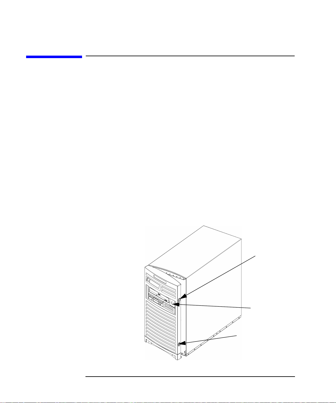
Changing Your Computer Hardware Configuration
System Unit Front Panel
System Unit Front Panel
This section explains how to open and close the system unit’s front panel.
Opening the System Unit Front Panel
Perform the following steps to open the system unit.
1. Power off the system, and unplug the system unit power cord from
the electrical outlet. Note that when you press the system power
switch, the system automatically performs a shutdown -q.
2. Attach the static-grounding wrist strap by following the instructions
on the package. Attach the sticky end of the wrist strap to bare metal
on the back panel of the system unit.
3. Unlatch the front panel (also known as the front bezel) by pressing in
on the two latch buttons located on the right side of the front panel.
See Figure 5-1. If the front panel does not open, you may have to
locate the front panel key and unlock it.
Figure 5-1 Opening the Front Panel
98 Chapter5
Bezel Latch
Button
Bezel
Lock
Bezel Latch
Button
Page 99

Changing Your Computer Hardware Configuration
System Unit Front Panel
4. Swing the panel outward on its left snap hinges until the panel comes
free and place the front panel in a location where it cannot get
broken.
Closing the System Unit Front Panel
Perform the following steps to close the system unit.
1. Locate the hinges on the left side of the front panel, and insert them
into the holes located along the left edge of the system unit.
2. Rotate the front panel inward until you hear the two latch buttons
snap in place. The front panel is now closed. If there is a need to lock
the front panel, use the system unit keys that came with your system
to lock the panel. These keys are located inside the front bezel below
the floppy disk drive.
3. Plug in the system unit power cord, and power on the system.
Chapter 5 99
Page 100

Changing Your Computer Hardware Configuration
Left Side Panel of the System Unit
Left Side Panel of the System Unit
This section explains how to open and close the left side panel of the
system unit. This side panel will have to be opened whenever you need
access to the internal components of the computer.
Opening the Left Side Panel of the System Unit
Perform these steps to open the left side panel.
NOTE When you remove the left side panel, the system unit’s safety interlock
release pin will come out of the safety interlock switch and shutdown the
system without performing the proper shutdown sequences. See Figure
5-2. Therefore, before taking the left side panel of your computer off, do a
reboot -h or press the soft power switch on the front panel of your
computer. Either of these actions will gracefully power down the system.
1. Power off the system, and unplug the system unit power cord from
the electrical outlet.
2. Attach the static-grounding wrist strap by following the instructions
on the package. Attach the sticky end of the wrist strap to bare metal
on the back panel of the system unit.
3. Turn the computer around so its back is facing you. On the right edge
of the computer, there are two T-15 Torx thumbscrews as shown in
Figure 5-2. Remove the two T-15 Torx thumbscrews.
100 Chapter5
 Loading...