

Page 1

HPE AR44z Server User Guide
Abstract
This document is for the person who installs, administers, and troubleshoots server and
storage systems. Hewlett Packard Enterprise assumes you are qualified in the servicing of
computer equipment and trained in recognizing hazards in products with hazardous energy
levels.
Part Number: P03078-003
Published: July 2019
Edition: 3
Page 2

©
Copyright 2018–2019 Hewlett Packard Enterprise Development LP
Notices
The information contained herein is subject to change without notice. The only warranties for Hewlett
Packard Enterprise products and services are set forth in the express warranty statements accompanying
such products and services. Nothing herein should be construed as constituting an additional warranty.
Hewlett Packard Enterprise shall not be liable for technical or editorial errors or omissions contained
herein.
Confidential computer software. Valid license from Hewlett Packard Enterprise required for possession,
use, or copying. Consistent with FAR 12.211 and 12.212, Commercial Computer Software, Computer
Software Documentation, and Technical Data for Commercial Items are licensed to the U.S. Government
under vendor's standard commercial license.
Links to third-party websites take you outside the Hewlett Packard Enterprise website. Hewlett Packard
Enterprise has no control over and is not responsible for information outside the Hewlett Packard
Enterprise website.
Acknowledgments
AMI® and MegaRAC® are trademarks of American Megatrend Incorporation.
Arm® is a registered trademark of Arm Limited (or its subsidiaries) in the U.S. and/or elsewhere.
Linux® is the registered trademark of Linus Torvalds in the U.S. and other countries.
Marvell® and ThunderX2® are registered trademarks of Marvell and/or its affiliates.
Mellanox® is a trademark of Mellanox Technologies, Ltd.
Red Hat® Enterprise Linux® are registered trademarks of Red Hat, Inc. in the United States and other
countries.
Page 3

Contents
HPE Apollo 70 System............................................................................6
Component identification.......................................................................7
Operations............................................................................................. 14
Rear panel components................................................................................................................7
Server information pull tab................................................................................................. 7
Rear panel LEDs and button.........................................................................................................8
Server UID LED..................................................................................................................8
System board components........................................................................................................... 9
System maintenance switch descriptions........................................................................ 10
DIMM slot locations.......................................................................................................... 11
DIMM label identification.................................................................................................. 11
System component health status................................................................................................13
Power up the server....................................................................................................................14
Power down the server............................................................................................................... 14
Remove the server......................................................................................................................14
Install the server..........................................................................................................................15
BMC configuration...................................................................................................................... 16
Accessing the system health log.................................................................................................16
Setup...................................................................................................... 18
General site planning.................................................................................................................. 18
HPE Installation Service............................................................................................................. 18
Product QuickSpecs................................................................................................................... 18
Compiling the documentation..................................................................................................... 18
Setting up the system................................................................................................................. 18
Operational requirements........................................................................................................... 20
Site requirements............................................................................................................. 20
Space and airflow requirements.......................................................................................20
Temperature requirements...............................................................................................21
Power requirements......................................................................................................... 21
Grounding requirements.................................................................................................. 21
Device bay thermal requirements.................................................................................... 21
Rack warnings and cautions....................................................................................................... 22
Server warnings and cautions.....................................................................................................23
Electrostatic discharge................................................................................................................23
Locating the IP address.............................................................................................................. 24
OS deployment options...............................................................................................................24
Deploying an OS from an installation media.................................................................... 24
Linux OS documentation and download resource........................................................... 25
Hardware options installation..............................................................26
Introduction................................................................................................................................. 26
SUV cable option........................................................................................................................ 26
3
Page 4

Using an SUV cable for a KVM setup.............................................................................. 26
Using an SUV cable to access USB drives in a KVM setup............................................ 27
Memory options...........................................................................................................................27
DIMM population information........................................................................................... 27
Installing a DIMM..............................................................................................................27
M.2 SATA SSD option................................................................................................................. 30
Installing an M.2 SATA SSD.............................................................................................31
RAID configuration........................................................................................................... 31
OCP network adapter option.......................................................................................................32
Installing the OCP network adapter................................................................................. 32
Transceiver option.......................................................................................................................34
Transceiver warnings and cautions..................................................................................34
Installing a transceiver..................................................................................................... 35
Software and configuration utilities.................................................... 37
HPE Performance Cluster Manager........................................................................................... 37
HPE Message Passing Interface................................................................................................ 37
AMI MegaRAC SP-X GUI........................................................................................................... 37
AMI Aptio Setup Utility................................................................................................................ 37
Launching the Embedded UEFI Shell ............................................................................. 37
USB support................................................................................................................................38
External USB support.......................................................................................................38
Keeping the system current........................................................................................................ 38
Updating firmware using IPMItool ................................................................................... 38
Drivers..............................................................................................................................39
Downloading software and firmware updates.................................................................. 39
Operating system version support................................................................................... 39
HPE Pointnext Portfolio.............................................................................................................. 39
Proactive notifications................................................................................................................. 39
System battery replacement................................................................ 41
System battery information......................................................................................................... 41
Removing and replacing the system battery...............................................................................41
Safety, warranty, and regulatory information..................................... 43
Regulatory information................................................................................................................43
Notices for Eurasian Economic Union..............................................................................43
Turkey RoHS material content declaration.......................................................................44
Ukraine RoHS material content declaration..................................................................... 44
Warranty information...................................................................................................................44
Specifications........................................................................................45
Environmental specifications...................................................................................................... 45
Limited system operating temperature requirements.......................................................45
Mechanical specifications........................................................................................................... 46
Websites................................................................................................ 47
Support and other resources...............................................................48
Accessing Hewlett Packard Enterprise Support......................................................................... 48
4
Page 5

Accessing updates......................................................................................................................48
Customer self repair....................................................................................................................49
HPE Proactive Care service........................................................................................................49
Documentation feedback............................................................................................................ 49
Acronyms and abbreviations...............................................................50
5
Page 6

HPE Apollo 70 System
The HPE Apollo 70 System is an Arm-based platform that delivers the density and scalability required for
large HPC cluster deployments. The system is powered by Marvell 64-bit Arm v8-A ThunderX2
processors with maximum DDR4 memory bandwidth and Mellanox interconnect fabric options in a
compact 2U form factor.
The HPE Apollo 70 System consists of the:
• HPE Apollo z70 Chassis ─ 2U chassis with an eight-bay LFF drive cage, eight single-rotor fans, and
two HPE Flexible Slot Power Supply bays.
• HPE Apollo server nodes:
◦ HPE AR44z Server ─ 1U server node, maximum of four nodes per chassis
◦ HPE AR64z Server ─ 2U server node, maximum of two nodes per chassis
6 HPE Apollo 70 System
Page 7
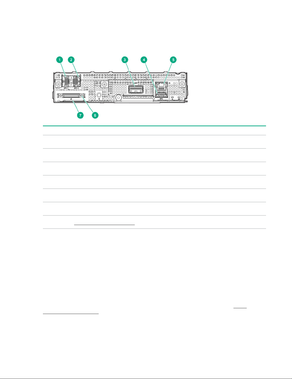
Component identification
Rear panel components
Item Description
1 SFP+ port 1
2 SFP+ port 2
3 QSFP port (optional)
4 USB 3.0 port
5 Dedicated management NIC port
6 SUV port
7 Server information pull tab on page 7
1
These ports support both SFP and SFP+ DAC and AOC connections, as well as SFP and SFP+ transceiver module
installation.
1
1
Server information pull tab
A double-sided server information pull tab is located in the port side of the server node. The following
server labels are attached to this pull tab:
• Top side ─ Factory default BMC user name and password label and the QR code label that also
shows the MAC addresses for the LOM and BMC.
• Reverse side ─ Server serial number and product ID labels
Use a mobile device to scan the QR code label to display the server mobile product page (
www.hpe.com/qref/ar44z). This page contains links to the server setup information, spare part numbers,
QuickSpecs, and other useful product links.
Component identification 7
http://
Page 8
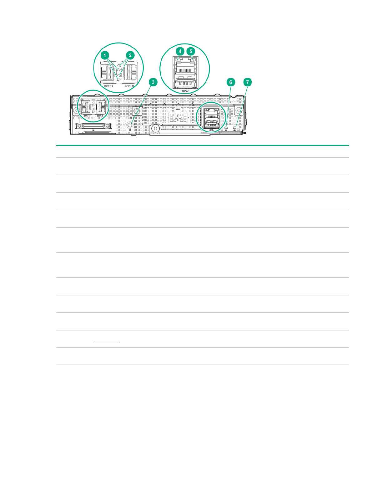
Rear panel LEDs and button
Item Description Status Definition
1 and 5 NIC link LED Solid green Network link
Off No network link
2 and 4 NIC status LED Flashing green Network active
3 Power On/Standby button
6 Reserved
7 UID LED Flashing blue Activated
1
Facility power is not present, power cord is not attached, no power supplies are installed, power supply failure has
occurred, or the front I/O cable is disconnected.
Server UID LED
and system power LED
Off No network activity
Solid green System on and normal
operation
Flashing green Performing power-on
sequence
Solid amber System in standby
Off No power present
— —
Off Deactivated
1
The UID LED is used to locate a particular server when it is deployed in a dense rack with many other
servers. Activating the UID LED allows an onsite technician to quickly identify a server for maintenance
tasks.
8 Component identification
Page 9
Authorized users can remotely toggle the UID LED on and off using the IPMI tool. When activated
through IPMItool, the UID LED will continue to flash blue until it is turned off again in IPMItool.
Remotely toggling the server UID LED on and off
Prerequisites
This procedure is done in the IPMItool CLI. If this tool is not yet installed, download the tool from the
Sourceforge website (https://sourceforge.net/projects/ipmitool.)
Procedure
1. To open a Linux terminal, click Applications > Terminal.
2. Do one of the following:
• To remotely turn on the UID LED, enter the following command:
ipmitool -H <IP> -U admin -P <Password> raw 0x00 0x04 0x00 0x01 turn on UID LED
The UID LEDs on the server and on the chassis flashes blue.
• To remotely turn off the UID LED, enter the following command:
ipmitool -H <IP> -U admin -P <Password> raw 0x00 0x04 0x00 0x01 turn off UID LED
Where:
IP is the server IP address.
Password is the AMI MegaRAC SP-X GUI login password.
3. Close the Linux terminal.
The procedure is complete.
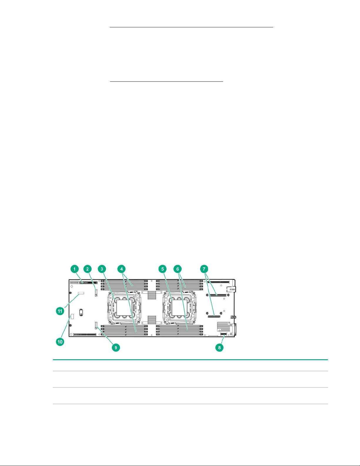
System board components
Item Description
1 Bayonet board connector
2 M.2 slot for processor 2(A)
Table Continued
Component identification 9
Page 10

Item Description
3 Processor 2(A)
4 DIMM slots for processor 2(A)
5 Processor 1(B)
6 DIMM slots for processor 1(B)
7 OCP network adapter connectors
8 SFP+ riser connector
9 M.2 slot for processor 1(B)
10
11 System battery
System maintenance switch
System maintenance switch descriptions
Position Default Function
S1 Off
S2 Off
S4 Off
S3, S5 to
S12
— Reserved
Off = Processor UART output is enabled.
On = BMC UART output is enabled.
Off = Processor UART output is from the SUV port.
On = Processor UART output is from the BMC (for SOL).
Off = Connection from the dedicated management NIC port to the BMC is
enabled.
On = Connection from the IPMI ports on the RCM module to the BMC is
enabled.
10 Component identification
Page 11
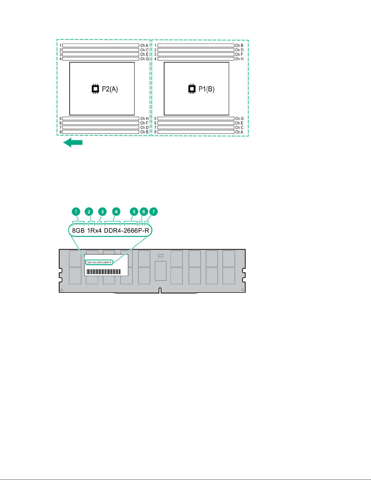
DIMM slot locations
The arrow in the image points to the direction of the front chassis.
DIMM label identification
To determine DIMM characteristics, see the label attached to the DIMM. The information in this section
helps you to use the label to locate specific information about the DIMM.
Component identification 11
Page 12

Item Description Example
1 Capacity
2 Rank
3 Data width on DRAM
4 Memory generation
8 GB
16 GB
32 GB
64 GB
128 GB
1R = Single rank
2R = Dual rank
4R = Quad rank
8R = Octal rank
x4 = 4-bit
x8 = 8-bit
x16 = 16-bit
PC4 = DDR4
5 Maximum memory speed
6 CAS latency
7 DIMM type
2133 MT/s
2400 MT/s
2666 MT/s
2933 MT/s
P = CAS 15-15-15
T = CAS 17-17-17
U = CAS 20-18-18
V = CAS 19-19-19 (for RDIMM, LRDIMM)
V = CAS 22-19-19 (for 3DS TSV LRDIMM)
Y = CAS 21-21-21 (for RDIMM, LRDIMM)
Y = CAS 24-21-21 (for 3DS TSV LRDIMM)
R = RDIMM (registered)
L = LRDIMM (load reduced)
12 Component identification
E = Unbuffered ECC (UDIMM)
Page 13

For more information about product features, specifications, options, configurations, and compatibility, see
the HPE DDR4 SmartMemory QuickSpecs on the Hewlett Packard Enterprise website (http://
www.hpe.com/support/DDR4SmartMemoryQS).
System component health status
The Sensor Monitoring list in the Dashboard page of the AMI MegaRAC SP-X GUI shows the health
status of individual system components. More detailed sensor information is available in the Server
Health > Sensor Readings page.
For more information, see the HPE Apollo 70 System BMC Web UI User Guide on the Hewlett Packard
Enterprise website (http://www.hpe.com/support/apollo70-BMC-UG).
Component identification 13
Page 14

Operations
Power up the server
The chassis firmware initiates an automatic power-up sequence when the servers are installed. If the
default setting is changed, use one of the following methods to power up each server:
Procedure
• Select a power up action in the AMI MegaRAC SP-X GUI.
• Press and release the Power On/Standby button.
When the server goes from standby mode to full power mode, the power LED changes from amber to
green.
Power down the server
IMPORTANT: When the server is in standby mode, auxiliary power is still being provided to the
system.
Prerequisites
Before powering down the server for any upgrade or maintenance procedures, perform a backup of
critical server data and programs.
Procedure
• Press and release the Power On/Standby button.
This method initiates a controlled shutdown of applications and the OS before the server enters
standby mode.
• Press and hold the Power On/Standby button for more than 4 seconds to force the server to enter
standby mode.
This method forces the server to enter standby mode without properly exiting applications and the OS.
If an application stops responding, you can use this method to force a shutdown.
• Select a power down action in the AMI MegaRAC SP-X GUI.
This method initiates a controlled remote shutdown of applications and the OS before the server
enters standby mode.
Before proceeding, verify that the server is in standby mode by observing that the power LED is amber.
Remove the server
CAUTION: To prevent improper cooling and thermal damage, do not operate the chassis unless all
bays are populated with a component or a blank.
CAUTION: To avoid damage to the server or server blank:
• Always support the bottom of the server or server blank when removing it from the chassis.
• Do not use the release lever to carry the server or server blank.
14 Operations
Page 15
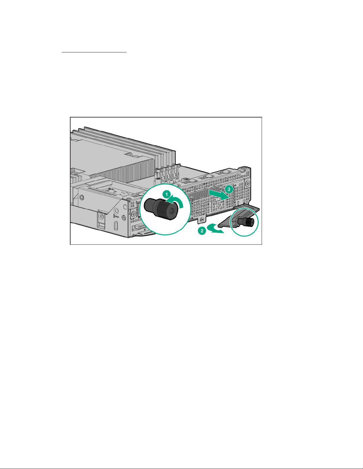
Procedure
1. Back up all server data.
2. Power down the server on page 14.
3. Disconnect all peripheral cables from the server.
4. Remove the server:
a. Loosen the release lever thumbscrew.
b. Open the release lever.
c. Use the release lever to pull the server out of the chassis.
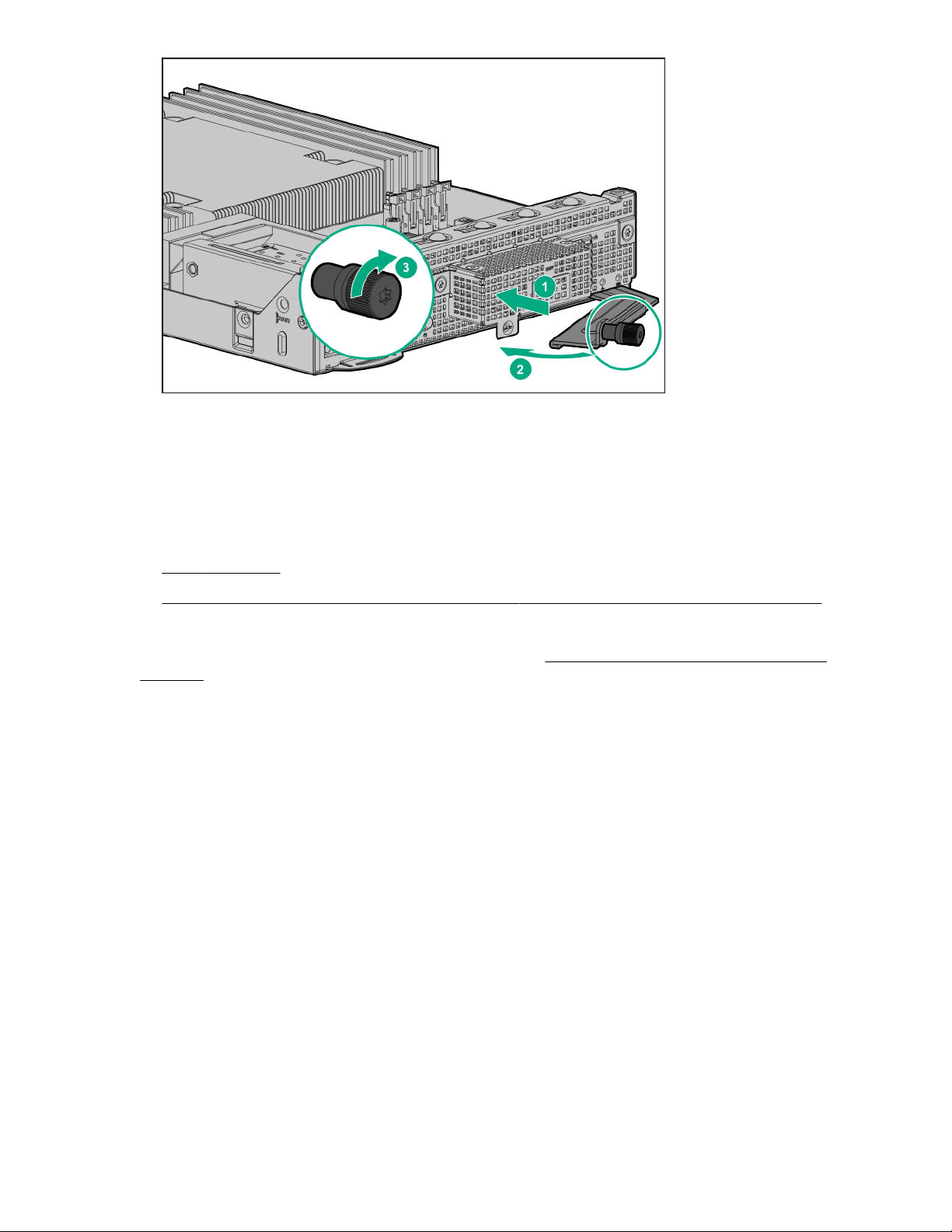
Install the server
Procedure
1. Slide the server into the chassis.
2. Close the release lever.
3. Tighten the release lever thumbscrew.
Operations 15
Page 16
BMC configuration
The BMC is the remote server management processor embedded on the server. The AMI MegaRAC SPX GUI is the software component of the system remove server management solution. Use the browserbased MegaRAC SP-X GUI to remotely monitor and configure the server.
For first-time login to the AMI MegaRAC SP-X GUI, you need the:
BMC IP address
•
• Factory default user name and password on the server serial number information pull tab
For more information on using the AMI MegaRAC SP-X GUI, see the HPE Apollo 70 System BMC Web
UI User Guide on the Hewlett Packard Enterprise website (http://www.hpe.com/support/apollo70-
BMC-UG).
Accessing the system health log
The event log lists the events generated by the system sensors. The event entries have a time stamp of
when the event log was generated.
Procedure
1. In a remote browser, enter the BMC IP address, and then press Enter.
2. In the AMI MegaRAC SP-X GUI login page, enter the BMC user name and password, and then click
Login.
3. Click Server Health > Event Log.
4. Do one of the following:
• To view an event, click the event ID, and then press Enter.
• To customize the event log display, select an option from the event log category and sensor
16 Operations
drop‑down menus.
Page 17

• To download an event log as an Excel sheet, click Save Event Logs.
• To delete all events from the log, click Clear All Event Logs.
Operations 17
Page 18

Setup
General site planning
Before you begin installing the HPE Apollo 70 System, Hewlett Packard Enterprise recommends that you
plan and coordinate the installation process with an authorized HPE representative or partner. Proper
planning provides a more efficient installation process and leads to greater availability, reliability, and
serviceability of the system.
HPE Installation Service
HPE Installation Service provides basic installation of Hewlett Packard Enterprise branded equipment,
software products, as well as HPE-supported products from other vendors that are sold by HPE or by
HPE authorized resellers. The Installation Service is part of a suite of HPE deployment services that are
designed to give users the peace of mind that comes from knowing that their HPE and HPE-supported
products have been installed by an HPE specialist.
The HPE Installation Service provides the following benefits:
• Installation by an HPE authorized technical specialist.
• Verification prior to installation that all service prerequisites are met.
• Delivery of the service at a mutually scheduled time convenient to your organization.
• Allows your IT resources to stay focused on their core tasks and priorities.
• Full coverage during the warranty period for products that require installation by an HPE authorized
technical specialist.
For more information on the features, limitations, provisions, and ordering information of the HPE
Installation Service, see this Hewlett Packard Enterprise website:
http://www.hpe.com/support/installation-service
Product QuickSpecs
For more information about product features, specifications, options, configurations, and compatibility, see
the product QuickSpecs on the Hewlett Packard Enterprise website (http://www.hpe.com/info/qs).
Compiling the documentation
The documentation, while delivered individually and in various formats, works as a system. Consult these
documents before attempting installation. These documents provide the required important safety
information and decision-making steps for the configuration. To access these documents, see the Hewlett
Packard Enterprise website (http://www.hpe.com/info/apollo70-docs).
Setting up the system
Prerequisites
Before installing the server node in the chassis, be sure to do the following:
• Note the factory default BMC user name and password on the server information pull tab.
• Read the following:
18 Setup
◦ Operational requirements on page 20
◦ Safety and compliance information on the HPE website:
Page 19

http://www.hpe.com/support/safety-compliance-enterpriseproducts
◦ Rack warnings and cautions on page 22
◦ Server warnings and cautions on page 23
Procedure
1. Unbox the server node and verify the contents:
• Server node
• Documentation
2. (Optional) Install the server hardware options. For installation instructions, see Hardware options
installation on page 26.
3. Install the server into the chassis.
4. Connect all peripheral cables to the servers and chassis.
5. Connect each power cord to the chassis.
6. Connect each power cord to the power source.
7. Decide how to manage the server:
• To manage the server locally, use an SUV cable for a KVM setup.
• To manage the server remotely, you will need a remote browser to connect to the AMI MegaRAC
SP-X GUI.
a. Verify that a network cable is connected to the dedicated management NIC port.
b. Locate the BMC IP address:
◦ If a DHCP server assigns the IP address, locate the IP address.
◦ If a static IP address is assigned, use that IP address.
c. In a remote browser, type the IP address, and then press Enter.
d. In the AMI MegaRAC SP-X GUI login page, enter the factory default BMC user name and
password, and then click Login.
e. In the Dashboard menu, click Launch.
The remote management Java console window appears.
8. Do one of the following:
• If you are managing the server locally, press the Power On/Standby button.
• If you are managing the server remotely, in the AMI MegaRAC SP-X GUI:
a. Select Remote Control > Server Power Control.
b. Select a power on action.
c. Click Perform Action.
9. Deploy an OS or virtualization software.
Setup 19
Page 20

10. As a best practice, Hewlett Packard Enterprise recommends that you install the latest
firmware, drivers, and system software before using the server for the first time.
To get the latest firmware and software updates, see the server support page:
https://www.hpe.com/support/ar44z
11. Register the system (https://myenterpriselicense.hpe.com).
Operational requirements
Site requirements
The server must be located in a computer room or server room. The room must:
• Be only accessible to authorized technicians trained the room restriction reasons and precautions.
• Be within an area that is ideally locked or at minimum not accessible to unauthorized personnel.
Space and airflow requirements
To allow for servicing and adequate airflow, observe the following space and airflow requirements when
deciding where to install a rack:
• Leave a minimum clearance of 63.5 cm (25 in) in front of the rack.
• Leave a minimum clearance of 76.2 cm (30 in) behind the rack.
• Leave a minimum clearance of 121.9 cm (48 in) from the back of the rack to the back of another rack
or row of racks.
Hewlett Packard Enterprise servers draw in cool air through the front door and expel warm air through the
rear door. Therefore, the front and rear rack doors must be adequately ventilated to allow ambient room
air to enter the cabinet, and the rear door must be adequately ventilated to allow the warm air to escape
from the cabinet.
CAUTION: To prevent improper cooling and damage to the equipment, do not block the ventilation
openings.
When vertical space in the rack is not filled by a server or rack component, the gaps between the
components cause changes in airflow through the rack and across the servers. Cover all gaps with
blanking panels to maintain proper airflow.
CAUTION: Always use blanking panels to fill empty vertical spaces in the rack. This arrangement
ensures proper airflow. Using a rack without blanking panels results in improper cooling that can
lead to thermal damage.
CAUTION: If a third-party rack is used, observe the following additional requirements to ensure
adequate airflow and to prevent damage to the equipment:
• Front and rear doors—If the 42U rack includes closing front and rear doors, you must allow
5,350 sq cm (830 sq in) of holes evenly distributed from top to bottom to permit adequate airflow
(equivalent to the required 64 percent open area for ventilation).
20 Setup
• Side—The clearance between the installed rack component and the side panels of the rack must
be a minimum of 7 cm (2.75 in).
Page 21

Temperature requirements
To ensure continued safe and reliable equipment operation, install or position the system in a wellventilated, climate-controlled environment.
The maximum recommended ambient operating temperature (TMRA) for most server products is 35°C
(95°F). The temperature in the room where the rack is located must not exceed 35°C (95°F).
CAUTION: To reduce the risk of damage to the equipment when installing third-party options:
• Do not permit optional equipment to impede airflow around the server or to increase the internal
rack temperature beyond the maximum allowable limits.
• Do not exceed the manufacturer’s TMRA.
Power requirements
Installation of this equipment must comply with local and regional electrical regulations governing the
installation of IT equipment by licensed electricians. This equipment is designed to operate in installations
covered by NFPA 70, 1999 Edition (National Electric Code) and NFPA-75, 1992 (code for Protection of
Electronic Computer/Data Processing Equipment). For electrical power ratings on options, refer to the
product rating label or the user documentation supplied with that option.
WARNING: To reduce the risk of personal injury, fire, or damage to the equipment, do not overload
the AC supply branch circuit that provides power to the rack. Consult the electrical authority having
jurisdiction over wiring and installation requirements of your facility.
CAUTION: Protect the server from power fluctuations and temporary interruptions with a regulating
UPS. This device protects the hardware from damage caused by power surges and voltage spikes
and keeps the server in operation during a power failure.
Grounding requirements
• The building installation must provide a means of connection to protective earth.
• The equipment must be connected to that means of connection.
• A service person must check whether the socket-outlet from which the equipment is to be powered
provides a connection to the building protective earth. If the outlet does not provide a connection, the
service person must arrange for the installation of a protective earthing conductor from the separate
protective earthing terminal to the protective earth wire in the building.
Device bay thermal requirements
Operate the chassis only when a device or blank is installed in all device bays. Before powering up the
chassis, be sure to do the following:
• Install a drive or drive blank into all drive bays.
• Install a server or a blank into all server bays.
• Install a power supply or power supply blank into all power supply bays.
Setup 21
Page 22

Rack warnings and cautions
WARNING: When all components are removed, the system weighs 17.21 kg (37.94 lb). When all
components are installed, the system can weigh up to 22.65 kg (49.93 lb).
Before configuring your rack solution, be sure to check the rack manufacturer weight limits and
specifications. Failure to do so can result in physical injury or damage to the equipment and the
facility.
WARNING: To reduce the risk of personal injury or damage to the equipment, be sure that:
• The rack has anti-tip measures in place. Such measures include floor-bolting, anti-tip feet,
ballast, or a combination as specified by the rack manufacturer and applicable codes.
• The leveling jacks (feet) are extended to the floor.
• The full weight of the rack rests on the leveling jacks (feet).
• The stabilizing feet are attached to the rack if it is a single-rack installation.
• The racks are coupled together in multiple rack installations.
WARNING: The chassis is heavy. To reduce the risk of personal injury or damage to the equipment,
do the following:
• Observe local occupational health and safety requirements and guidelines for manual material
handling.
• Get help to lift and stabilize the product during installation or removal, especially when the
product is not fastened to the rails. The chassis weighs more than 17.21 kg (37.94 lb), so at least
two people must lift the chassis into the rack together. An additional person may be required to
help align the chassis if the chassis is installed higher than chest level.
• Use caution when installing the chassis into or removing the chassis from the rack.
• Adequately stabilized the chassis before extending a component outside the rack. Extend only
one component at a time. The rack might become unstable if more than one component is
extended.
• Do not stack anything on top of rail-mounted component or use it as a work surface when
extended from the rack.
WARNING: The rack rails form only a shelf for the chassis to rest on. The chassis is not attached to
the rails by any other means. Slipping and falling chassis will cause bodily injury or damage the
chassis, so use extreme care when pulling the chassis out from the rack. Hewlett Packard
Enterprise is not responsible for any injury or damage caused by the mishandling of the chassis.
CAUTION: Before installing the system into a rack, be sure to properly scope the limitations of the
rack. Before proceeding with the installation, consider the following:
22 Setup
• You must fully understand the static and dynamic load carrying capacity of the rack and be sure
that it can accommodate the maximum weight of the system.
• Be sure sufficient clearance exists for cabling, installation and removal of the system, and
movement of the rack doors.
Page 23

CAUTION: Always plan the rack installation so that the heaviest item is on the bottom of the rack.
Install the heaviest item first, and continue to populate the rack from the bottom to the top.
Server warnings and cautions
WARNING: To reduce the risk of personal injury, electric shock, or damage to the equipment,
disconnect the power cord to remove power from the server. Pressing the Power On/Standby button
does not shut off system power completely. Portions of the power supply and some internal circuitry
remain active until AC power is removed.
WARNING: To reduce the risk of personal injury from hot surfaces, allow the drives and the internal
system components to cool before touching them.
WARNING: To reduce the risk of electric shock or damage to the equipment:
• Never reach inside the chassis while the system is powered up.
• Perform service on system components only as instructed in the user documentation.
CAUTION: Protect the server from power fluctuations and temporary interruptions with a regulating
UPS. This device protects the hardware from damage caused by power surges and voltage spikes
and keeps the server in operation during a power failure.
CAUTION: To prevent damage to electrical components, properly ground the server before
beginning any installation procedure. Improper grounding can cause electrostatic discharge.
CAUTION: To avoid data loss, Hewlett Packard Enterprise recommends that you back up all server
data before installing or removing a hardware option, or performing a server maintenance or
troubleshooting procedure.
CAUTION: To prevent improper airflow and insufficient cooling that can lead to thermal damage,
observe the following:
• Do not operate the chassis without the access panel, baffles, or blanks installed.
• Do not operate the server without the baffles, expansion slot covers, or blanks installed.
Electrostatic discharge
Be aware of the precautions you must follow when setting up the system or handling components. A
discharge of static electricity from a finger or other conductor may damage system boards or other staticsensitive devices. This type of damage may reduce the life expectancy of the system or component.
To prevent electrostatic damage:
• Avoid hand contact by transporting and storing products in static-safe containers.
• Keep electrostatic-sensitive parts in their containers until they arrive at static-free workstations.
• Place parts on a grounded surface before removing them from their containers.
Setup 23
Page 24

• Avoid touching pins, leads, or circuitry.
• Always be properly grounded when touching a static-sensitive component or assembly. Use one or
more of the following methods when handling or installing electrostatic-sensitive parts:
◦ Use a wrist strap connected by a ground cord to a grounded workstation or computer chassis. Wrist
straps are flexible straps with a minimum of 1 megohm ±10 percent resistance in the ground cords.
To provide proper ground, wear the strap snug against the skin.
◦ Use heel straps, toe straps, or boot straps at standing workstations. Wear the straps on both feet
when standing on conductive floors or dissipating floor mats.
◦ Use conductive field service tools.
◦ Use a portable field service kit with a folding static-dissipating work mat.
If you do not have any of the suggested equipment for proper grounding, have an authorized reseller
install the part.
For more information on static electricity or assistance with product installation, contact an authorized
reseller.
Locating the IP address
Procedure
1. Press the Power On/Standby button.
2. Access the Aptio V Setup Utility. During POST, press Del or Esc.
3. Select Server Mgmt > BMC network configuration, and then press Enter.
4. Note the station IP address value.
OS deployment options
• For single server OS deployment, use an OS installation media (USB key or DVD).
• For multiple server OS deployment in a cluster, use HPE Performance Cluster Manager.
Deploying an OS from an installation media
Procedure
1. Verify that the OS is supported:
http://www.hpe.com/info/ossupport
2. Insert the installation media.
3. Do one of the following:
• If you are managing the server locally, access the AMI Aptio V Setup Utility by pressing Del or Esc
during POST, and then set the boot option priority by selecting Boot > Boot Option Priorties.
4. Deploy the OS.
24 Setup
• If you are managing the server remotely, in the Java console window, select Media > Virtual Media
Wizard, and then select the OS installation media.
Page 25

Linux OS documentation and download resource
For the latest Linux OS documentation and downloads, see the following resources:
• Red Hat Enterprise Linux Server
◦ Red Hat software and downloads: https://access.redhat.com/downloads
A paid subscription is required for downloading from this Red Hat download site. However, you can
request a free evaluation subscription at the same site.
◦ Red Hat product documentation: https://access.redhat.com/documentation/en-us/
red_hat_enterprise_linux
• SUSE Linux Enterprise Server
◦ SUSE Linux Enterprise Server: http://suse.com/download-linux
A paid subscription is required for downloading some products from this SUSE download site.
However, you can request a free evaluation subscription at the same site.
◦ SUSE product documentation: https://www.suse.com/documentation
The Red Hat and SUSE links listed here will take you outside the Hewlett Packard Enterprise website.
Hewlett Packard Enterprise has no control over and is not responsible for information outside the Hewlett
Packard Enterprise website.
Setup 25
Page 26
Hardware options installation
Introduction
Install any hardware options before initializing the server. For options installation information, see the
option documentation. For server-specific information, use the procedures in this section.
If multiple options are being installed, read the installation instructions for all the hardware options to
identify similar steps and streamline the installation process.
WARNING: To reduce the risk of personal injury from hot surfaces, allow the drives and the internal
system components to cool before touching them.
CAUTION: To prevent damage to electrical components, properly ground the server before
beginning any installation procedure. Improper grounding can cause electrostatic discharge.
SUV cable option
CAUTION: To avoid equipment damage when removing the SUV cable, press and hold the release
buttons on the SUV cable connector before disconnecting the cable from the SUV port.
Use an SUV cable to perform server administration, configuration, and diagnostic procedures by
connecting video and USB devices directly to the server.
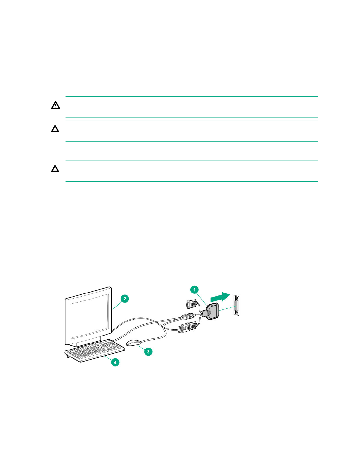
Using an SUV cable for a KVM setup
Procedure
1. Connect the SUV cable to the SUV port.
2. Connect a monitor to the video connector.
3. Connect a USB mouse to the second USB connector.
4. Connect a USB keyboard to the other USB connector.
26 Hardware options installation
Page 27
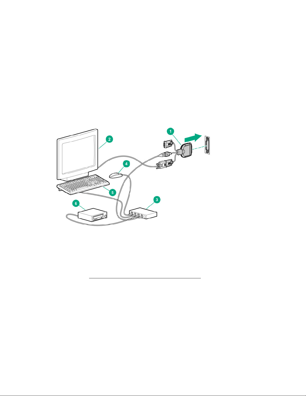
Using an SUV cable to access USB drives in a KVM setup
The USB connectors on the SUV cable do not support USB devices that require a power source greater
than 500 mA at 5 V. When accessing this type of USB drives, such as a USB key or a USB optical drive,
use a USB hub in a KVM setup.
Procedure
1. Connect the SUV cable to the SUV port.
2. Connect a monitor to the video connector.
3. Connect a USB hub to the USB connector.
4. Connect a USB mouse to the USB hub.
5. Connect a USB keyboard to the USB hub.
6. Connect a USB key or a USB optical drive to the USB hub.
Memory options
DIMM population information
For specific DIMM population information, see the DIMM population guidelines on the Hewlett Packard
Enterprise website (http://www.hpe.com/docs/arm-population-rules).
Installing a DIMM
Prerequisites
• Note the following regarding the server memory support:
◦ A dual-processor server configuration requires the installation of at least two DIMMs.
◦ This server does not support the earlier DDR3 memory generation.
• If you are installing a processor 1(B) DIMM and an OCP network adapter is installed, make sure that
you have a T-15 Torx screwdriver available.
Hardware options installation 27
Page 28
Procedure
1. Power down the server on page 14.
2. Disconnect all peripheral cables from the server.
3. Remove the server from the chassis.
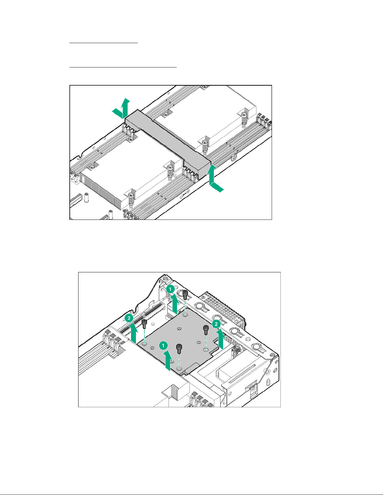
4. Remove the server air baffle.
5. If you are installing a processor 1(B) DIMM and an OCP network adapter is installed, remove the
OCP air baffle:
a. Loosen one pair of diagonally opposite screws halfway, and then loosen the other pair of screws.
b. Completely remove all screws in the same sequence.
c. Disconnect the OCP network adapter from the system board.
d. Tilt the OCP network adapter away from the rear bracket.
28 Hardware options installation
Page 29
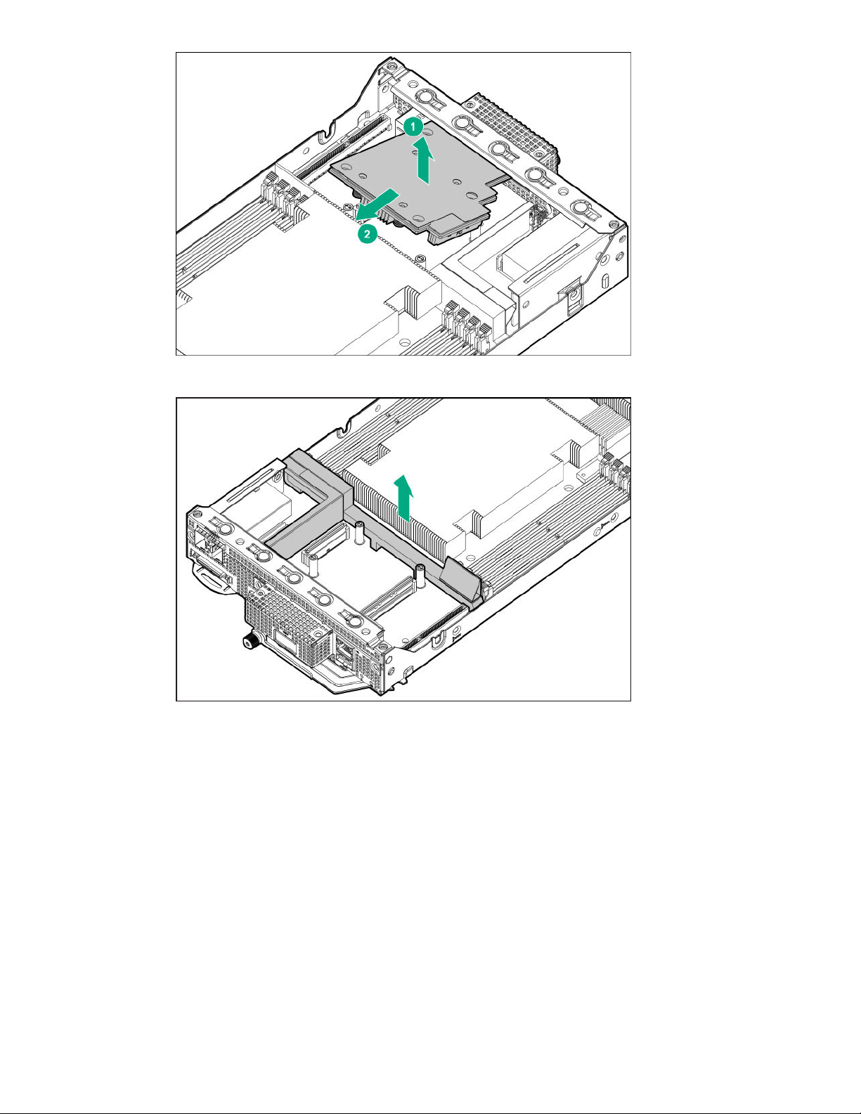
e. Remove the OCP air baffle.
6. Install the DIMM:
a. Open the DIMM slot latches.
b. Align the notch on the bottom edge of the DIMM with the keyed surface of the DIMM slot, and
then fully press the DIMM into the slot until the latches snap back into place.
Hardware options installation 29
Page 30
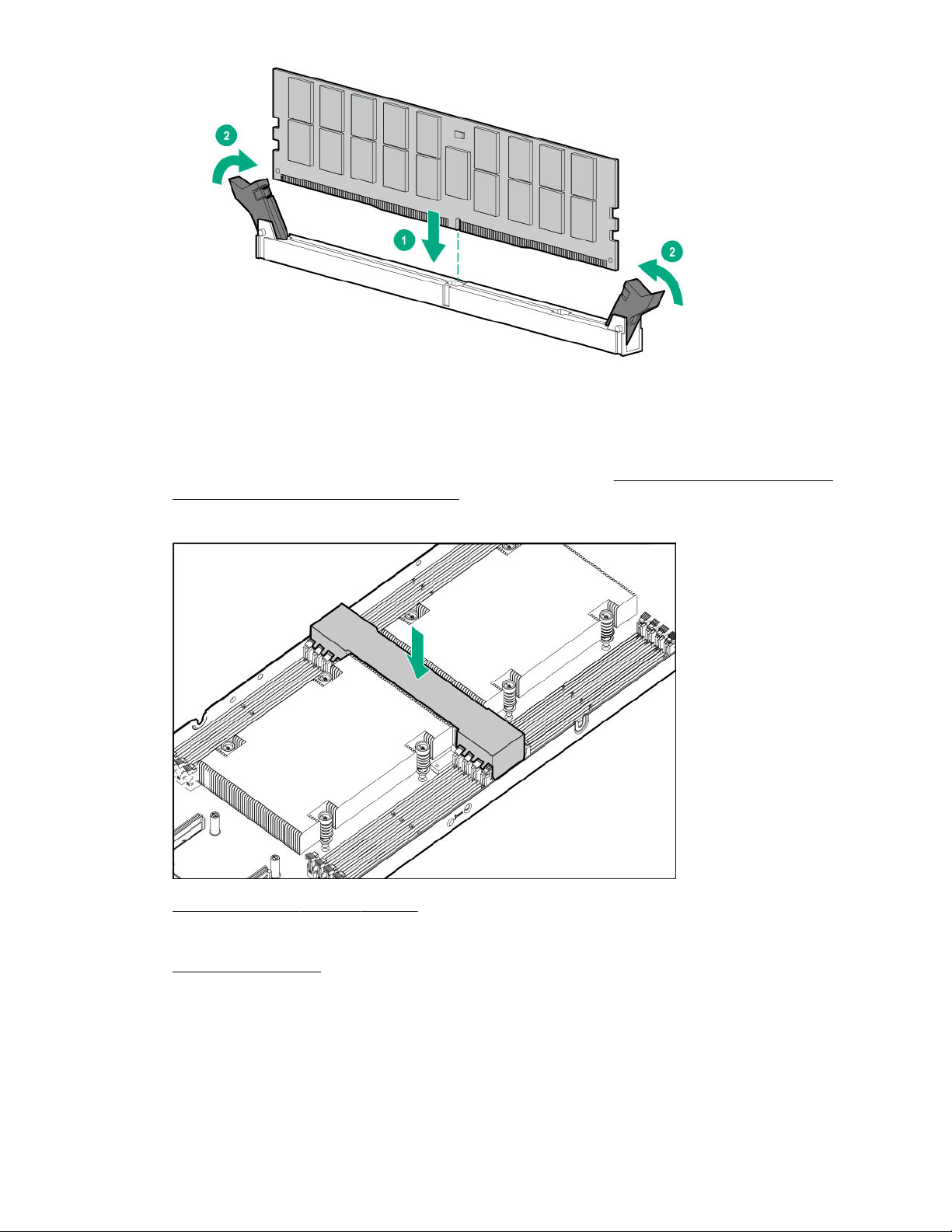
The DIMM slots are structured to ensure proper installation. If you try to insert a DIMM but it does
not fit easily into the slot, you might have positioned it incorrectly. Reverse the orientation of the
DIMM and insert it again.
7. If removed, install the OCP air baffle and OCP network adapter. Perform steps 5–6 of the OCP
network adapter installation procedure.
8. Install the server air baffle.
9. Install the server into the chassis.
10. Connect all peripheral cables to the server.
11. Power up the server on page 14.
The installation is complete.
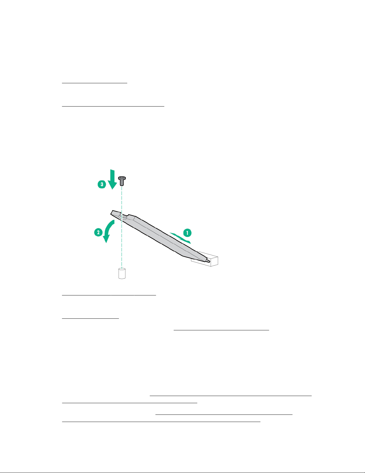
M.2 SATA SSD option
The server has two M.2 slots that support M.2 2280 SATA SSDs.
30 Hardware options installation
Page 31
Installing an M.2 SATA SSD
Prerequisites
Before you perform this procedure, make sure that you have a Phillips No. 2 screwdriver available.
Procedure
1. Power down the server on page 14.
2. Disconnect all peripheral cables from the server.
3. Remove the server from the chassis.
4. Install the SSD:
a. Insert the SSD into the M.2 slot at a 45° angle.
b. Carefully press the SSD down to the horizontal position.
c. Install the SSD mounting screw.
5. Install the server into the chassis.
6. Connect all peripheral cables to the server.
7. Power up the server on page 14.
8. To configure the M.2 SATA SSDs, see the OS software RAID documentation.
The installation is complete.
RAID configuration
The HPE Apollo 70 System supports software RAID only. For OS-specific RAID information, see the
following resources:
• SUSE Linux Enterprise Server ─ https://www.suse.com/documentation/sles-12/singlehtml/
stor_admin/stor_admin.html#part.software_raid
• Red Hat Enterprise Linux Server ─ https://access.redhat.com/documentation/en-us/
red_hat_enterprise_linux/7/html/storage_administration_guide/ch-raid
Hardware options installation 31
Page 32
The Red Hat and SUSE links listed here will take you outside the Hewlett Packard Enterprise website.
Hewlett Packard Enterprise has no control over and is not responsible for information outside the Hewlett
Packard Enterprise website.
OCP network adapter option
Installing the OCP network adapter
CAUTION: EMI disturbs the normal functioning of an electronic device. To maintain proper EMI
shielding, do not operate the system when the QSFP port knockout or the OCP network adapter is
not installed.
Prerequisites
Before you perform this procedure, make sure that you have the following items available:
• Flathead screwdriver
• T-15 Torx screwdriver
Procedure
1. Power down the server on page 14.
2. Disconnect all peripheral cables from the server.
3. Remove the server from the chassis.
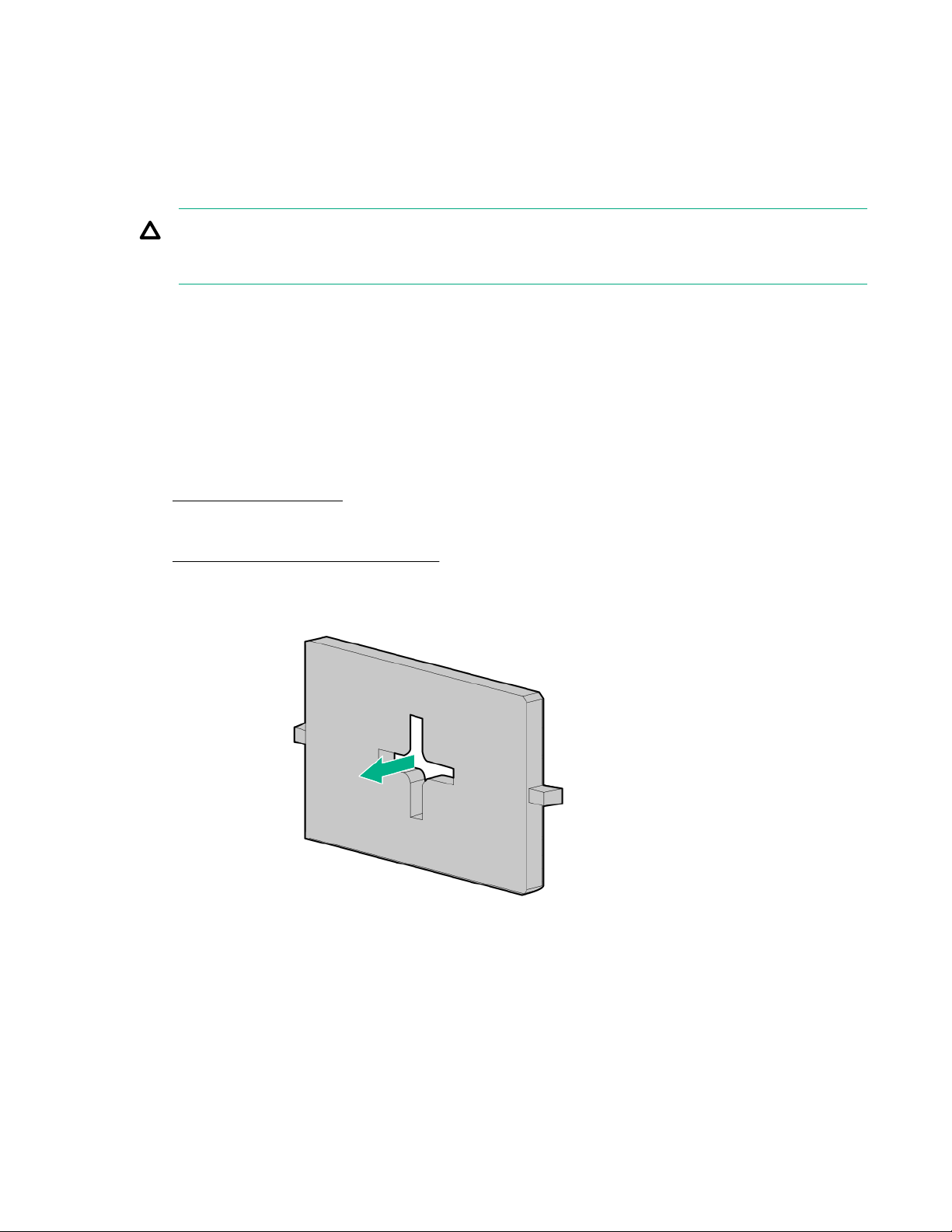
4. Using a flat screwdriver, toggle the QSFP port knockout to loosen it, and then pull the knockout out of
the rear bracket.
5. Install the OCP air baffle.
32 Hardware options installation
Page 33
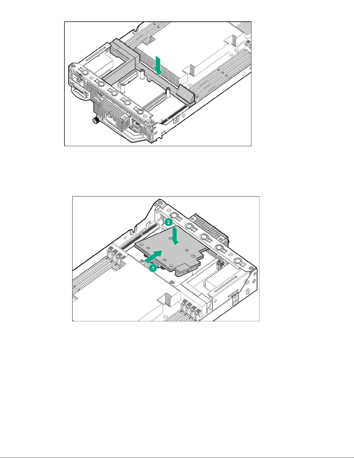
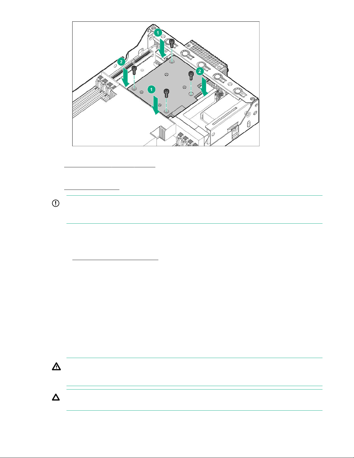
6. Install the OCP network adapter:
a. Align the port side of the OCP network adapter in the rear bracket.
b. Press the OCP network adapter down to ensure that the adapter is firmly seated on the
connectors.
c. Install one pair of diagonally opposite screws halfway, and then install the other pair of screws.
The installation is finished by completely tightening the screws in the same sequence.
Hardware options installation 33
Page 34
7. Install the server into the chassis.
8. Connect all peripheral cables to the server.
9. Power up the server on page 14.
IMPORTANT: If you have installed the HPE EDR InfiniBand/Ethernet 100Gb single-port 841OCP
QSFP28 Adapter, use a passive direct attach copper cable (DACC). An active optical cable (AOC)
is not supported.
10. Do one of the following:
• Connect the LAN segment cable.
• Install a compatible transceiver.
11. To verify that the OCP network adapter is working properly, check the OCP network adapter LEDs:
• NIC link status (left) = Solid green
• NIC status (right) = Flashing green
The installation is complete.
Transceiver option
Transceiver warnings and cautions
WARNING: Fiber-optic transceivers and fiber-optic cables connected to transceivers emit laser light
that can damage your eyes. To avoid eye injuries, avoid direct eye exposure to the beam from the
fiber-optic transceiver or into the ends of fiber-optic cables when they are powered-up.
CAUTION: The presence of dust in transceiver ports can cause poor cable connectivity. To prevent
dust from entering, install a dust plug in an unused transceiver port.
34 Hardware options installation
Page 35
CAUTION: Supported transceivers can be hot-swapped—removed and installed while the server is
powered-on. However, to prevent potential damage to the transceiver or the fiber-optic cable,
disconnect the cable from the transceiver before hot-swapping it.
CAUTION: Do not remove and install transceivers more often than is necessary. Doing so can
shorten the useful life of the transceiver.
IMPORTANT: When you replace a transceiver with another of a different type, the server might
retain selected port-specific configuration settings that were configured for the replaced transceiver.
Be sure to validate or reconfigure port settings as required.
Installing a transceiver
Prerequisites
Before installing a transceiver, be sure to read the following:
• If you are installing the transceiver in the QSFP port of the OCP network adapter, review the set
temperature requirements for this configuration.
• Transceiver warnings and cautions on page 34
• Transceiver documentation for specific operational and cabling requirements
Procedure
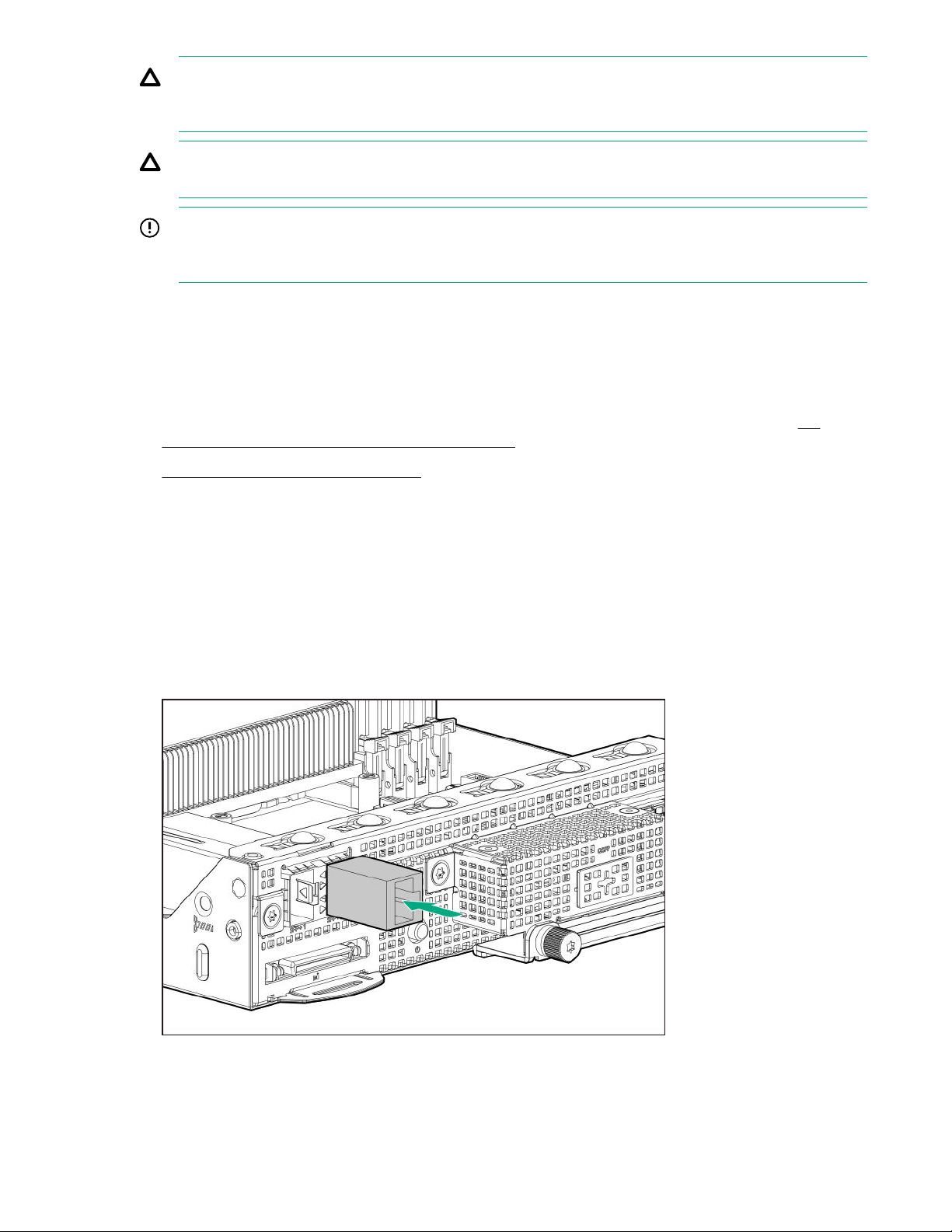
1. Hold the transceiver by its sides and gently insert it into the SFP+ or QSFP port until it clicks into
place.
Transceivers are keyed so that they can only be inserted in the correct orientation. If the transceiver
does not fit easily into the port, you might have positioned it incorrectly. Reverse the orientation of the
transceiver and insert it again.
2. Remove the dust plug or protective cover from the transceiver.
3. Connect a compatible LAN segment cable to the transceiver.
Hardware options installation 35
Page 36

4. Make sure that the NIC link LED on the SFP+ port is solid green.
For more information on the QSFP port LED behavior, see the documentation that ships with the
QSFP transceiver.
5. If needed, see the transceiver documentation for the model-specific fastening mechanism applicable
to the transceiver.
The installation is complete.
36 Hardware options installation
Page 37

Software and configuration utilities
HPE Performance Cluster Manager
HPE Performance Cluster Manager is a point of contact for the deployment, system management,
monitoring, and reporting on the HPE cluster system. For more information, see the HPE Performance
Cluster Manager documentation on the Hewlett Packard Enterprise website (
software/hpcm).
HPE Message Passing Interface
The HPE Message Passing Interface is an MPI development environment designed to enable the
development and optimization of high performance computing (HPC) Linux applications. The HPE
Message Passing Interface leverages a scalable MPI library and takes advantage of the underlying
server infrastructure by boosting performance of existing MPI applications on Hewlett Packard Enterprise
HPC clusters without requiring recompilation. For more information, see the HPE Message Passing
Interface documentation on the Hewlett Packard Enterprise website (
mpi).
AMI MegaRAC SP-X GUI
The AMI MegaRAC SP-X is a server management solution composed of both firmware and software
components. Use the browser-based MegaRAC SP-X GUI to remotely monitor and configure the server.
For more information, see the HPE Apollo 70 System BMC Web UI User Guide on the Hewlett Packard
Enterprise website (http://www.hpe.com/support/apollo70-BMC-UG).
http://www.hpe.com/software/
https://www.hpe.com/
AMI Aptio Setup Utility
The AMI Aptio V Setup Utility is embedded in the system ROM. This utility enables you to perform a wide
range of configuration activities, including the following:
• Configuring system devices and installed options
• Enabling and disabling system features
• Displaying system information
• Selecting the primary boot controller
• Configuring memory options
For more information, see the HPE Apollo 70 System UEFI User Guide on the Hewlett Packard
Enterprise website (http://www.hpe.com/support/apollo70-UEFI-UG).
Launching the Embedded UEFI Shell
Use the Built-in EFI Shell option to launch the Embedded UEFI Shell. The Embedded UEFI Shell is a
preboot command-line environment for scripting and running UEFI applications, including UEFI boot
loaders. The Shell also provides CLI-based commands you can use to obtain system information, and to
configure and update the system BIOS.
The Built-in EFI Shell is enabled by default.
Software and configuration utilities 37
Page 38

Procedure
1. Access the Aptio V Setup Utility. During POST, press Del or Esc.
2. To set the Built-in EFI Shell priority sequence in the predefined boot order settings, do the following:
a. Select Boot > Boot Option Priorities > UEFI: Built in EFI Shell, and then press Enter.
b. Set the preferred boot sequence for the Built-in EFI Shell.
c. Press F4 to save the boot selection, and then close the Setup Utility.
3. To select the Built-in EFI Shell for a one-time boot override, select Save & Exit, and then in the Boot
Override section, select UEFI: Built in EFI Shell.
4. If an administrator password is set, enter it at the prompt and press Enter.
The Shell> prompt appears.
5. Enter the commands required to complete your task.
6. Enter the exit command to exit the Shell.
USB support
Hewlett Packard Enterprise servers support all USB operating speeds depending on the device that is
connected to the server.
External USB support
Hewlett Packard Enterprise provides external USB support to enable local connection of USB devices for
server administration, configuration, and diagnostic procedures.
For additional security, the USB mass storage driver can be disabled in the Aptio V Setup Utility: Select
Advanced > USB Configuration > USB Mass Storage Driver.
Keeping the system current
Updating firmware using IPMItool
Prerequisites
• IPMItool. If this tool is not yet installed, download it from the Sourceforge website (https://
sourceforge.net/projects/ipmitool).
• Latest server firmware image bundle from the HPE Apollo 70 System support page (https://
www.hpe.com/support/apollo70).
• Red Hat Enterprise Linux 7.5 (or later) or SUSE Linux Enterprise Server 12 SP3 (or later).
Procedure
1. Extract the firmware image bundle.
2. To open a Linux terminal at the saved location, click Applications > Terminal.
3. Enter the command to update the firmware.
38 Software and configuration utilities
Page 39

For command information, see the README file located in the folder with the extracted image bundle.
4. Reboot the server.
A reboot is required after the firmware update to enable the updates and maintain hardware stability.
Drivers
IMPORTANT: Always perform a backup before installing or updating device drivers.
Tp update drivers, download specific drivers from the server download page.
To locate the drivers for a server, go to the Hewlett Packard Enterprise Support Center website, and
then search for the product name/number.
Downloading software and firmware updates
Update software and firmware before using the server for the first time, unless any installed software or
components require an older version.
For system software and firmware updates, download individual drivers, firmware, or other systems
software components from the server product page in the Hewlett Packard Enterprise Support Center
website (http://www.hpe.com/support/hpesc).
Operating system version support
For information about specific versions of a supported operating system, refer to the
support matrix.
HPE Pointnext Portfolio
HPE Pointnext delivers confidence, reduces risk, and helps customers realize agility and stability. Hewlett
Packard Enterprise helps customers succeed through Hybrid IT by simplifying and enriching the onpremise experience, informed by public cloud qualities and attributes.
Operational Support Services enable you to choose the right service level, length of coverage, and
response time to fit your business needs. For more information, see the Hewlett Packard Enterprise
website:
https://www.hpe.com/us/en/services/operational.html
Utilize the Advisory and Transformation Services in the following areas:
• Private or hybrid cloud computing
• Big data and mobility requirements
• Improving data center infrastructure
• Better use of server, storage, and networking technology
For more information, see the Hewlett Packard Enterprise website:
http://www.hpe.com/services/consulting
operating system
Proactive notifications
30 to 60 days in advance, Hewlett Packard Enterprise sends notifications to subscribed customers on
upcoming:
Software and configuration utilities 39
Page 40

• Hardware, firmware, and software changes
• Bulletins
• Patches
• Security alerts
You can subscribe to proactive notifications on the Hewlett Packard Enterprise website.
40 Software and configuration utilities
Page 41

System battery replacement
System battery information
The server contains an internal lithium manganese dioxide, a vanadium pentoxide, or an alkaline battery
that provides power to the real-time clock. If this battery is not properly handled, a risk of the fire and
burns exists. To reduce the risk of personal injury:
• Do not attempt to recharge the battery.
• Do not expose the battery to temperatures higher than 60°C (140°F).
• Do not disassemble, crush, puncture, short external contacts, or dispose the battery in fire or water.
• If the server no longer automatically displays the correct date and time, then replace the battery that
provides power to the real-time clock. Under normal use, battery life is 5 to 10 years.
Removing and replacing the system battery
Procedure
1. Power down the server on page 14.
2. Disconnect all peripheral cables from the server.
3. Remove the server on page 14.
4. Locate the battery on the system board.
5. Slightly push the metal tab, and then remove the system battery from the socket.
6. Slightly push the metal tab, and then install the new system battery in the socket.
System battery replacement 41
Page 42

7. Install the server on page 15.
8. Connect all peripheral cables to the server.
9. Power up the server on page 14.
10. Properly dispose of the old battery.
For more information about proper battery disposal, contact an authorized reseller or an authorized
service provider.
42 System battery replacement
Page 43

Safety, warranty, and regulatory information
Regulatory information
To view the regulatory information for your product, view the Safety and Compliance Information for
Server, Storage, Power, Networking, and Rack Products, available at the Hewlett Packard Enterprise
Support Center:
www.hpe.com/support/Safety-Compliance-EnterpriseProducts
Additional regulatory information
Hewlett Packard Enterprise is committed to providing our customers with information about the chemical
substances in our products as needed to comply with legal requirements such as REACH (Regulation EC
No 1907/2006 of the European Parliament and the Council). A chemical information report for this product
can be found at:
www.hpe.com/info/reach
For Hewlett Packard Enterprise product environmental and safety information and compliance data,
including RoHS and REACH, see:
www.hpe.com/info/ecodata
For Hewlett Packard Enterprise environmental information, including company programs, product
recycling, and energy efficiency, see:
www.hpe.com/info/environment
Notices for Eurasian Economic Union
Manufacturer and Local Representative Information
Manufacturer information:
Hewlett Packard Enterprise, 6280 America Center Drive, San Jose, CA 95002 U.S.
Local representative information Russian:
• Russia
ООО "Хьюлетт Паккард Энтерпрайз", Российская Федерация, 125171, г. Москва, Ленинградское
шоссе, 16А, стр.3, Телефон: +7 499 403 4248 Факс: +7 499 403 4677
• Kazakhstan
TOO «Хьюлетт-Паккард (К)», Республика Казахстан, 050040, г. Алматы, Бостандыкский район,
проспект Аль-Фараби, 77/7, Телефон/факс: + 7 727 355 35 50
Local representative information Kazakh:
• Russia
ЖШС "Хьюлетт Паккард Энтерпрайз", Ресей Федерациясы, 125171, Мәскеу, Ленинград тас
жолы, 16A блок 3, Телефон: +7 499 403 4248 Факс: +7 499 403 4677
• Kazakhstan
Safety, warranty, and regulatory information 43
Page 44

ЖШС «Хьюлетт-Паккард (К)», Қазақстан Республикасы, 050040, Алматы к., Бостандык ауданы,
Әл-Фараби даңғ ылы, 77/7, Телефон/факс: +7 727 355 35 50
Manufacturing date:
The manufacturing date is defined by the serial number.
If you need help identifying the manufacturing date, contact [email protected].
Turkey RoHS material content declaration
Türkiye Cumhuriyeti: AEEE Yönetmeliğine Uygundur
Ukraine RoHS material content declaration
Warranty information
To view the warranty information for your product, see the links provided below:
HPE ProLiant and IA-32 Servers and Options
www.hpe.com/support/ProLiantServers-Warranties
HPE Enterprise and Cloudline Servers
www.hpe.com/support/EnterpriseServers-Warranties
HPE Storage Products
www.hpe.com/support/Storage-Warranties
HPE Networking Products
www.hpe.com/support/Networking-Warranties
44 Safety, warranty, and regulatory information
Page 45

Specifications
Environmental specifications
Specification Value
System inlet temperature (standard operating
support
Operating 10°C to 35°C (50°F to 95°F)
Nonoperating -30°C to 60°C (-22°F to 140°F)
Relative humidity (noncondensing) —
Operating
Nonoperating
1
All temperature ratings shown are for sea level. An altitude derating of 1.0°C per 305 m (1.8°F per 1,000 ft) to 3,050
m (10,000 ft) is applicable. No direct sunlight allowed. Maximum rate of change is 20°C per hour (36°F per hour). The
upper limit and rate of change might be limited by the type and number of options installed. Under standard operating
support, a fan fault or the ambient temperature exceeding 30°C (86°F) might result in reduced system performance
issue.
1
—
8% to 90%
28°C (82.4°F), maximum wet bulb temperature
5% to 95%
38.7°C (101.7°F), maximum wet bulb temperature
Limited system operating temperature requirements
The maximum system operating temperature for most components installed in the server is 35°C (95°F).
However, some components in specific configurations are subject to thermal limitations. To ensure safe
and reliable system operation, observe the limited operating temperature for these configurations.
Temperature requirements for transceiver installation in the QSFP port
The following temperature values are valid for systems that have a homogenous node configuration.
Marvell ThunderX2
processor model
CN9975-2000 (150 W TDP) No ──
CN9980-2200 (180 W TDP) No ──
OCP network
adapter present
Yes Copper
Yes Fiber optic
QSFP port cable
type
Maximum inlet ambient
temperature
35°C (95°F)
35°C (95°F)
27°C (80.6°F)
23°C (73.4°F)
Table Continued
Specifications 45
Page 46

Marvell ThunderX2
processor model
OCP network
adapter present
QSFP port cable
type
Maximum inlet ambient
temperature
Yes Copper
Yes Fiber optic
Mechanical specifications
Specification Value
Dimensions
Height 4.05 cm (1.59 in)
Depth 67.27 cm (26.48 in)
Width 18.22 cm (7.17 in)
Weight (approximate values)
Weight, minimum 4.28 kg (9.43 lb)
23°C (73.4°F)
21°C (69.8°F)
—
—
Weight, maximum 4.66 kg (10.27 lb)
46 Specifications
Page 47

Websites
General websites
Hewlett Packard Enterprise Information Library
www.hpe.com/info/EIL
Subscription Service/Support Alerts
www.hpe.com/support/e-updates
Single Point of Connectivity Knowledge (SPOCK) Storage compatibility matrix
www.hpe.com/storage/spock
Storage white papers and analyst reports
www.hpe.com/storage/whitepapers
For additional general support websites, see Support and other resources.
Product websites
HPE Apollo 70 System product page
http://www.hpe.com/servers/apollo70
HPE AR44z Server support page
https://www.hpe.com/support/ar44z
HPE Apollo 70 System user documents
http://www.hpe.com/info/apollo70-docs
Websites 47
Page 48

Support and other resources
Accessing Hewlett Packard Enterprise Support
• For live assistance, go to the Contact Hewlett Packard Enterprise Worldwide website:
http://www.hpe.com/info/assistance
• To access documentation and support services, go to the Hewlett Packard Enterprise Support Center
website:
http://www.hpe.com/support/hpesc
Information to collect
• Technical support registration number (if applicable)
• Product name, model or version, and serial number
• Operating system name and version
• Firmware version
• Error messages
• Product-specific reports and logs
• Add-on products or components
• Third-party products or components
Accessing updates
• Some software products provide a mechanism for accessing software updates through the product
interface. Review your product documentation to identify the recommended software update method.
• To download product updates:
Hewlett Packard Enterprise Support Center
www.hpe.com/support/hpesc
Hewlett Packard Enterprise Support Center: Software downloads
www.hpe.com/support/downloads
Software Depot
www.hpe.com/support/softwaredepot
• To subscribe to eNewsletters and alerts:
www.hpe.com/support/e-updates
• To view and update your entitlements, and to link your contracts and warranties with your profile, go to
the Hewlett Packard Enterprise Support Center More Information on Access to Support Materials
page:
www.hpe.com/support/AccessToSupportMaterials
48 Support and other resources
Page 49

IMPORTANT: Access to some updates might require product entitlement when accessed through
the Hewlett Packard Enterprise Support Center. You must have an HPE Passport set up with
relevant entitlements.
Customer self repair
Hewlett Packard Enterprise customer self repair (CSR) programs allow you to repair your product. If a
CSR part needs to be replaced, it will be shipped directly to you so that you can install it at your
convenience. Some parts do not qualify for CSR. Your Hewlett Packard Enterprise authorized service
provider will determine whether a repair can be accomplished by CSR.
For more information about CSR, contact your local service provider or go to the CSR website:
http://www.hpe.com/support/selfrepair
HPE Proactive Care service
Proactive Care information
HPE Proactive Care Services
www.hpe.com/services/proactivecare
HPE Proactive Care Service: Supported products list
www.hpe.com/services/proactivecaresupportedproducts
HPE Proactive Care Advanced Service: Supported products list
www.hpe.com/services/proactivecareadvancedsupportedproducts
Proactive Care customer information
Proactive Care central
www.hpe.com/services/proactivecarecentral
Proactive Care service activation
www.hpe.com/services/proactivecarecentralgetstarted
Documentation feedback
Hewlett Packard Enterprise is committed to providing documentation that meets your needs. To help us
improve the documentation, send any errors, suggestions, or comments to Documentation Feedback
([email protected]). When submitting your feedback, include the document title, part number,
edition, and publication date located on the front cover of the document. For online help content, include
the product name, product version, help edition, and publication date located on the legal notices page.
Support and other resources 49
Page 50

Acronyms and abbreviations
3DS TSV
three-dimensional stacked through-silicon via (integrated circuit packaging technology)
AOC
active optical cable
BMC
baseboard management controller
CAS
column address strobe
CSR
customer self repair
DAC
direct attach cable
DACC
direct attach copper cable
DDR4
double data rate-4
DHCP
dynamic host configuration protocol
EAC
EurAsian Conformity
EDR
enhanced data rate
EMI
electromagnetic interference
HPC
high performance computing
IPMI
Intelligent Platform Management Interface
KVM
keyboard, video and mouse
LFF
large form factor
LRDIMM
load reduced dual in-line memory module
50 Acronyms and abbreviations
Page 51

MPI
Message Passing Interface
OCP
Open Compute Project
POST
Power-On Self-Test
QSFP
quad small form-factor pluggable
RDIMM
registered dual in-line memory module
REACH
Registration, Evaluation, Authorization, Restriction of Chemicals (European Union chemical regulatory
framework)
RoHS
Restriction of Hazardous Substances
SATA
serial ATA
SFP
small form-factor pluggable
SFP+
enhanced small form-factor pluggable
SOL
serial over LAN
SSD
solid state device
SUV
serial, USB, video
TDP
thermal design power
TMRA
recommended ambient operating temperature
UART
universal asynchronous receiver-transmitter
UDIMM
unbuffered dual in-line memory module
UEFI
Unified Extensible Firmware Interface
Acronyms and abbreviations 51
Page 52

UID
unit identification
UPS
uninterruptible power supply
52 Acronyms and abbreviations
 Loading...