

Page 1

HPE Apollo 70 System UEFI User Guide
Part Number: P06957-001
Published: June 2018
Edition: 1
Page 2

©
Copyright 2018 Hewlett Packard Enterpr ise Development LP
Notices
The information contained herein is subject to change without notice. The only warranties for Hewlett Packard
Enterprise products and services are set forth in the express warranty statements accompanying such products
and services. Nothing herein should be construed as constituting an additional warrant y. He wlett Packard
Enterprise shall not be liable for technical or editorial errors or omissions contained herein.
Confidential computer software. Valid license from Hewlett Packard Enterprise required for possession, use, or
copying. Consistent with FAR 12.211 and 12.212, Commercial Computer Software, Computer Software
Documentation, and Technical Data for Commercial Items are licensed to the U.S. Government under vendor's
standard commercial license.
Links to third-party websites take you outside the Hewlett Packard Enterprise website. Hewlett Packard Enterprise
has no control over and is not responsible for information outside the Hewlett Packard Enterprise website.
2
Page 3

......................................................................................................................... 5
................................................................................................................................... 6
........................................................................................................................... 9
............................................................................................................................. 20
............................................................................................................................ 21
24
....................................................................................................................... 26
....................................................................................................................... 27
Contents
ROM Setup
Bootup screen look and feel .......................................................................................................................................... 5
Main
BIOS Information ........................................................................................................................................................... 6
Platform Information ...................................................................................................................................................... 7
Memory Slot Information ............................................................................................................................................ 8
Advanced
Trusted Computing ...................................................................................................................................................... 10
ACPI Settings .............................................................................................................................................................. 11
ACPI Settings ........................................................................................................................................................... 11
Serial Port Console Redirection .................................................................................................................................. 12
Console Redirection Settings .................................................................................................................................. 13
Out-Of-Band Mgmt Port ........................................................................................................................................... 14
Network Stack Configuration ....................................................................................................................................... 15
NVMe Configuration .................................................................................................................................................... 16
SATA Configuration ..................................................................................................................................................... 17
USB Configuration ....................................................................................................................................................... 18
Driver Health ................................................................................................................................................................ 19
Chipset
SOC Configuration ...................................................................................................................................................... 20
Security
Secure Boot ................................................................................................................................................................. 22
System Mode ........................................................................................................................................................... 22
Key Management ..................................................................................................................................................... 23
Boot
Boot Configuration ....................................................................................................................................................... 24
Boot Option Priorities ................................................................................................................................................... 25
Save & Exit
Save Options ............................................................................................................................................................... 26
Default Options ............................................................................................................................................................ 26
Boot Override............................................................................................................................................................... 26
Event Logs
Change Smbios Event Log Settings ............................................................................................................................ 28
Enabling/Disabling Options ...................................................................................................................................... 28
3
Page 4

.................................................................................................................... 30
Erasing Settings ....................................................................................................................................................... 28
Smbios Event Log Standard Settings ...................................................................................................................... 28
Custom Options ....................................................................................................................................................... 28
View Smbios Event Log ............................................................................................................................................... 29
Server Mgmt
System Event Log ....................................................................................................................................................... 31
Enabling/Disabling Options ...................................................................................................................................... 31
Erasing Settings ....................................................................................................................................................... 31
Custom EFI Logging Options ................................................................................................................................... 31
View FRU information .................................................................................................................................................. 32
BMC network configuration ......................................................................................................................................... 33
BMC User Settings ...................................................................................................................................................... 34
Add User .................................................................................................................................................................. 35
Delete User .............................................................................................................................................................. 36
Change User Settings .............................................................................................................................................. 37
4
Page 5

ROM Setup
Bootup screen look and feel
Press <DEL> or <ESC> to Entering the Setup.
Press <F11> to Entering the Boot Menu.
Press <F12> to PXE Boot.
Press <Pause> to Pause the BIOS POST process.
Press <DEL> or <ESC> to
Entering the Setup.
Press <F11> to Entering the
Boot Menu.
Press <F12> to PXE Boot.
Press <Pause> to Pause the
5
Page 6
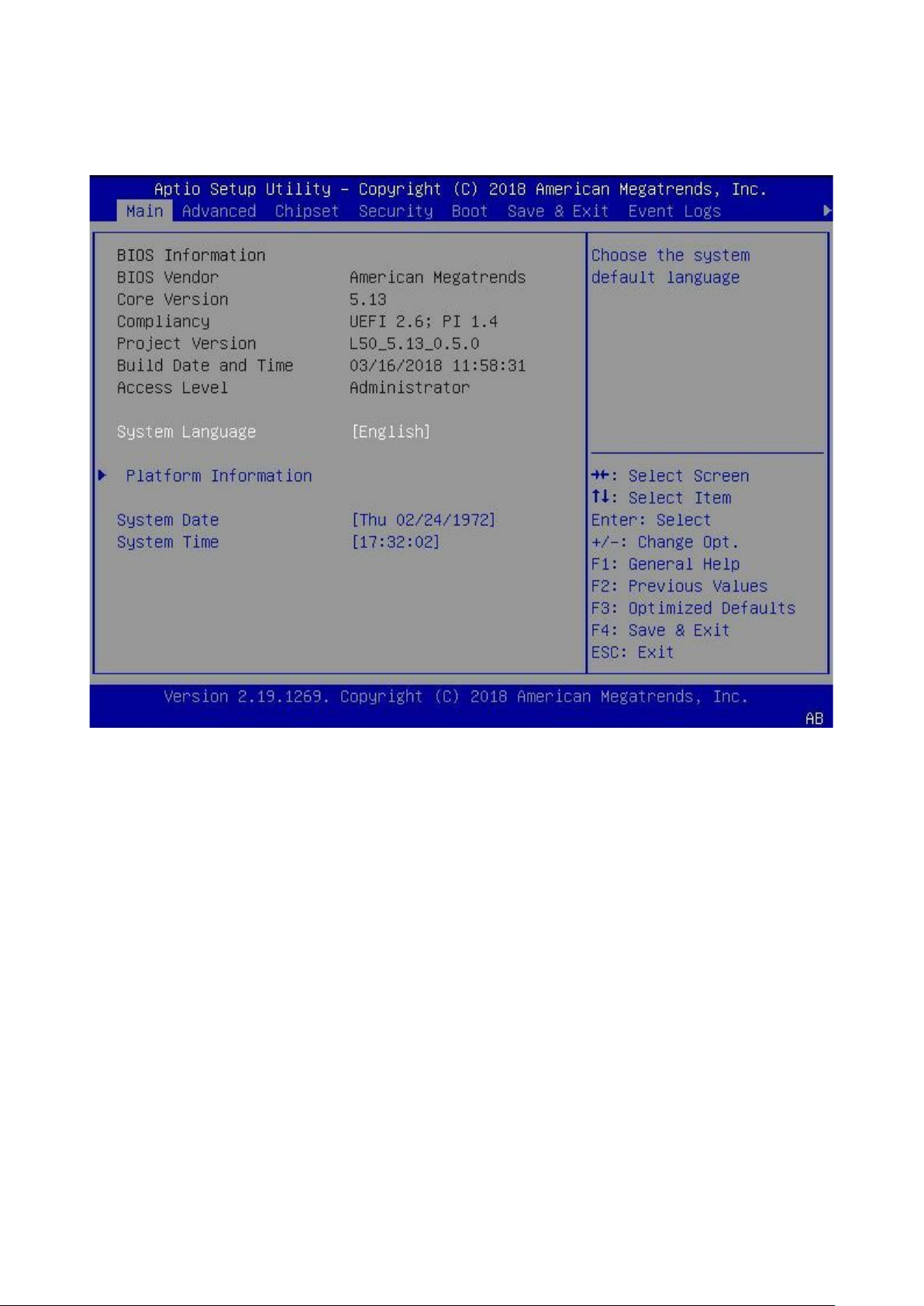
Main
The Main page of the Aptio Setup Utility provides information about the status of the device. To open the Main
page, click Main from the Step.
BIOS Information
BIOS Vendor:
Core Version:
Compliancy:
Project Version: The revision number of the firmware.
Build Date and Time: This field shows the date and time on which the firmware is built.
Access Level:
System Language: Select the system default language.
Platform Information: Information about this platform.
System Date: Use Tab to switch between Date elements.
Default Ranges: Year: 2005-2099 Months: 1-12 Days: dependent on month
System Time: Use Tab to switch between Time elements.
6
Page 7
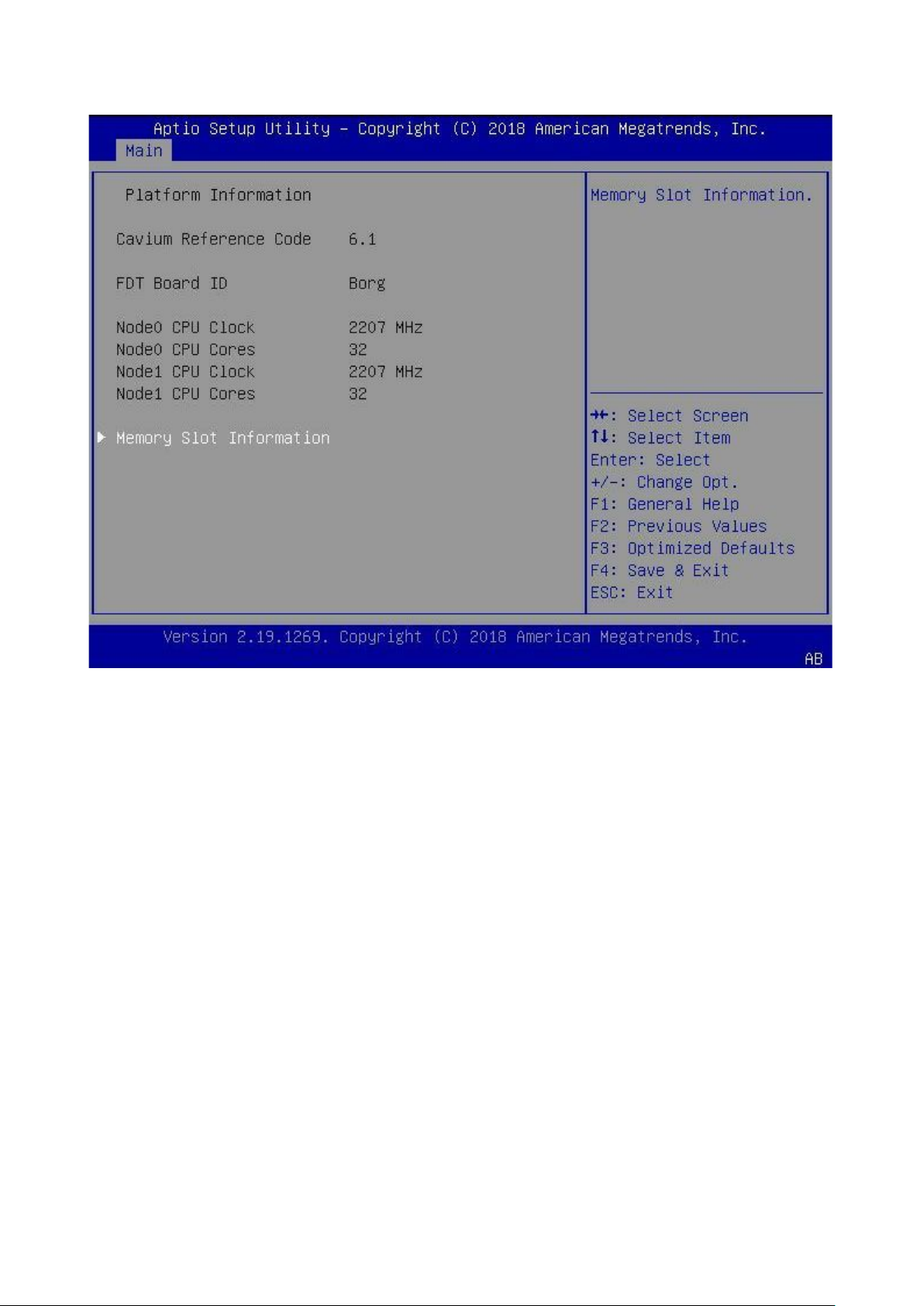
Platform Information
To open the Platform Information page, select Main Platform Information from the Aptio Setup Utility.
Cavium Reference Code Versio n: This field shows reference code version.
FDT Board ID: Displays Board ID.
Node0 CPU Clock: Displays the clock of CPU 0.
Node0 CPU Cores: Displays the number of CPU 0.
Node1 CPU Clock: Displays the clock of CPU 1.
Node1 CPU Cores: Displays the core number of CPU 1.
7
Page 8
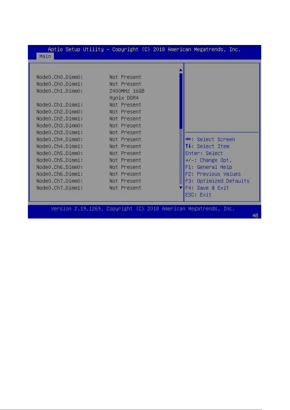
Memory Slot Information
To open the Memory Slot Information page, Select Main Platform Information Memory Slot
Information from the Aptio Setup Utility.
8
Page 9
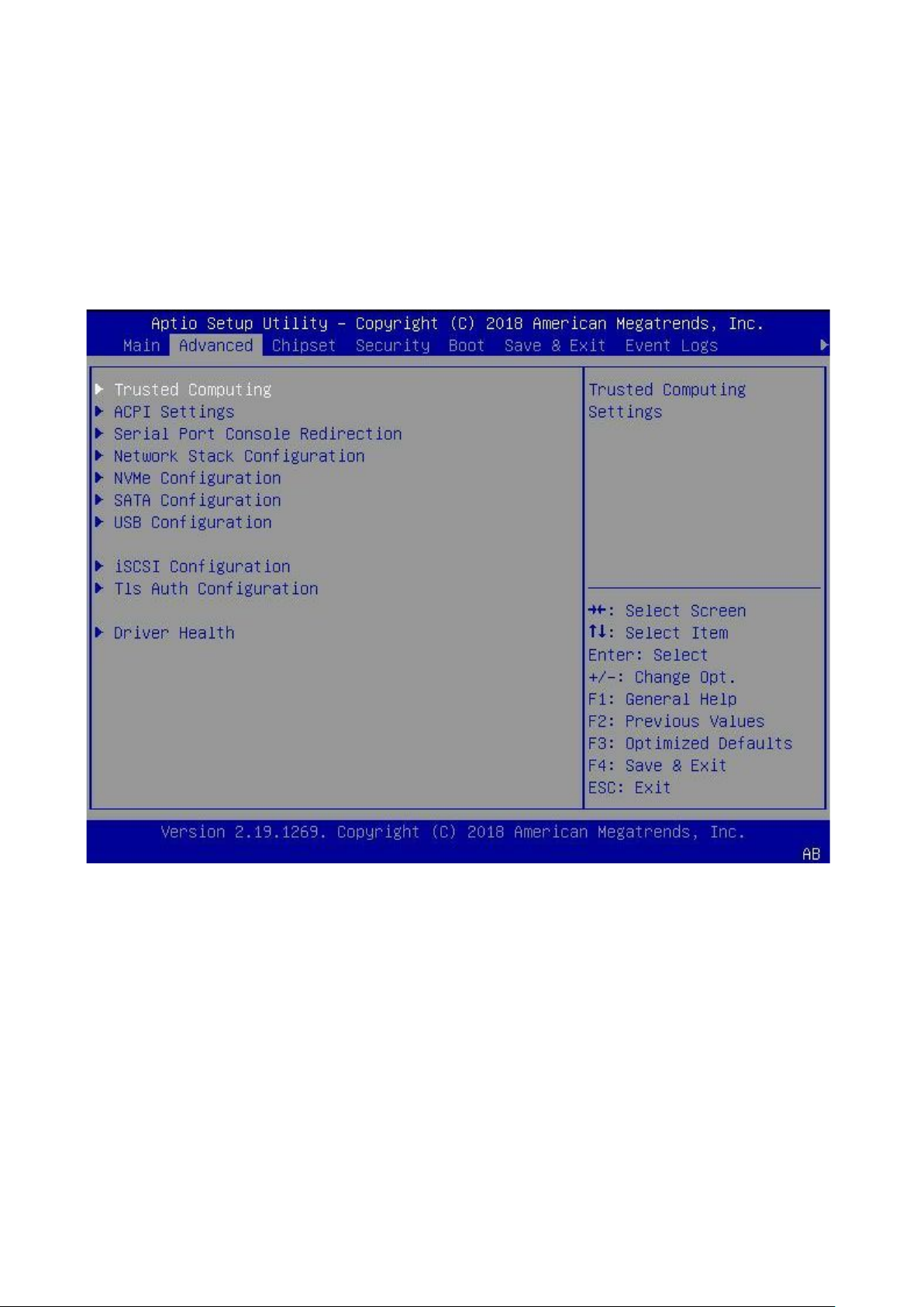
Advanced
The Advanced page displays the following information.
Trusted Computing
ACPI Settings
Serial Port Console Redirection
Network Stack Configuration
NVMe Configuration
SATA Configuration
USB Configuration
Driver Health
9
Page 10
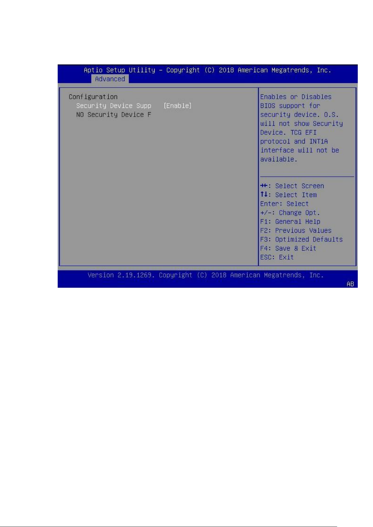
Trusted Computing
To open the Trusted Computing page, select Advanced Trusted Computing from the Aptio Setup
Utility.
Security Device Support: Enables or Disables BIOS support for security device. OS does not show a
Security Device. TCG EFI protocol and INT1A interface.
10
Page 11
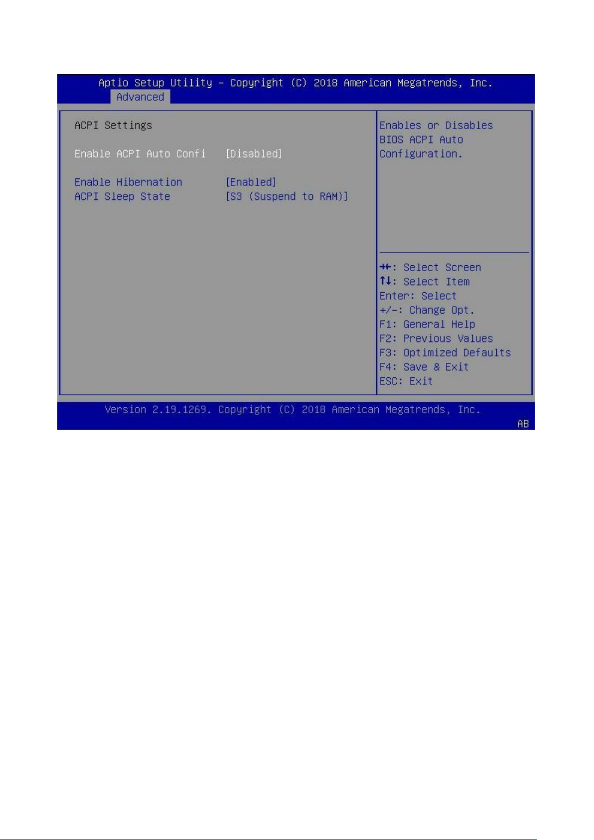
ACPI Settings
To open the ACPI Settings page, select Advanced ACPI Settings from the Aptio Setup Utility.
ACPI Settings
Enable ACPI Auto Configuration: Enables or Disables the BIOS ACPI Auto Conf igurat ion.
Enable Hibernation: Enables or Disables the system’s ability to Hibernate (OS/S4 Sleep State). This
option may not be available with some operating systems.
ACPI Sleep State: Select the highest ACPI sleep state the system enters when the SUSPEND button is
pressed.
11
Page 12
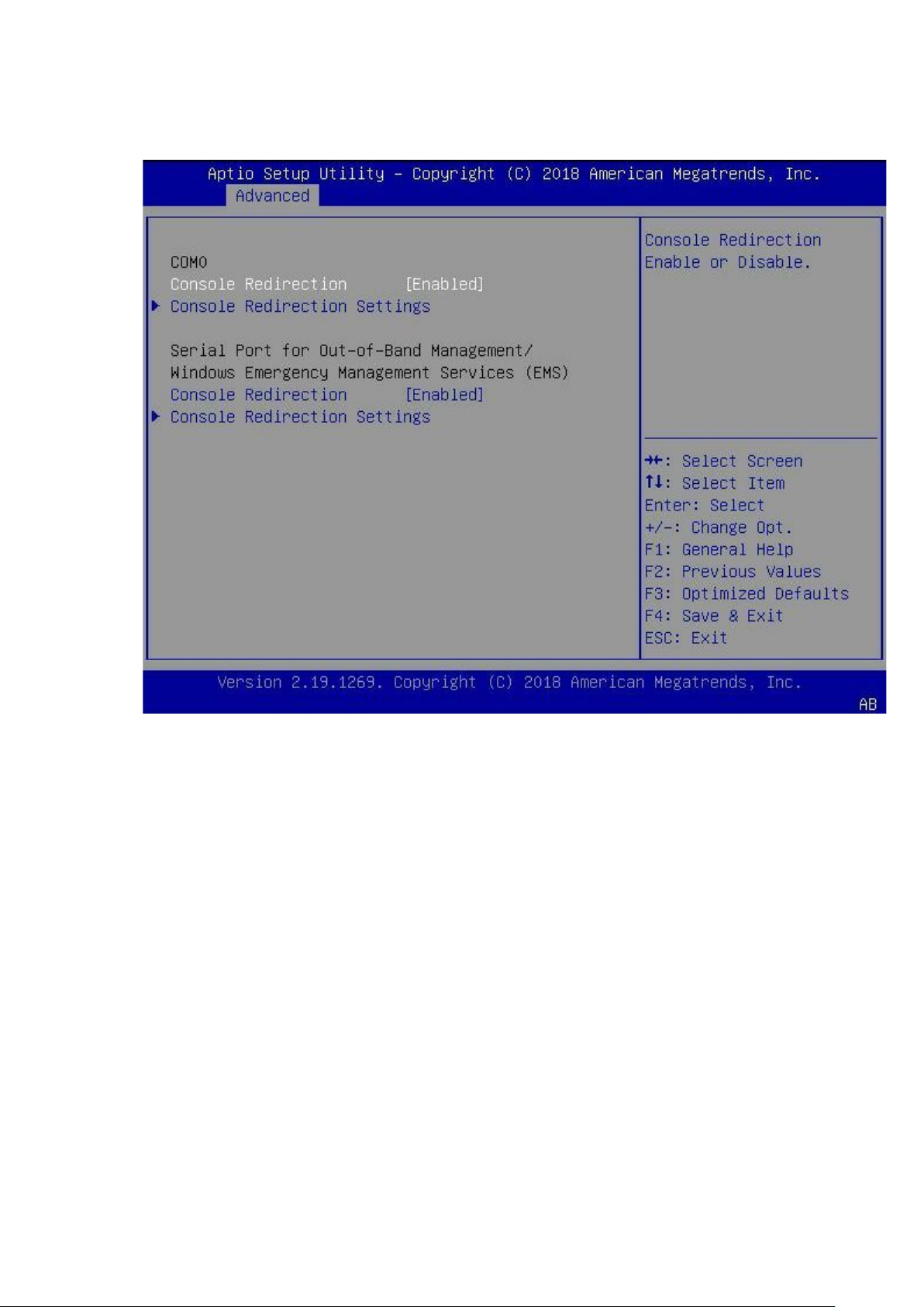
Serial Port Con sole Redirection
To open the Serial Port Console Redirection page, select Advanced Serial Port Console
Redirection from the Aptio Setup Utility.
COM0
Console Redirection: Enable or Disable Console Redirection.
Console Redirection Settings: How the host computer and the remote computer (which the user is
using) exchange data. Both computers.
Serial Port for Out-of-Band Management/Windows Emergency Management Services (EMS)
Console Redirection: Enable or Disable Console Redirection.
Console Redirection Settings: How the host computer and the remote computer (which the user is
using) exchanges data. Both computers.
12
Page 13
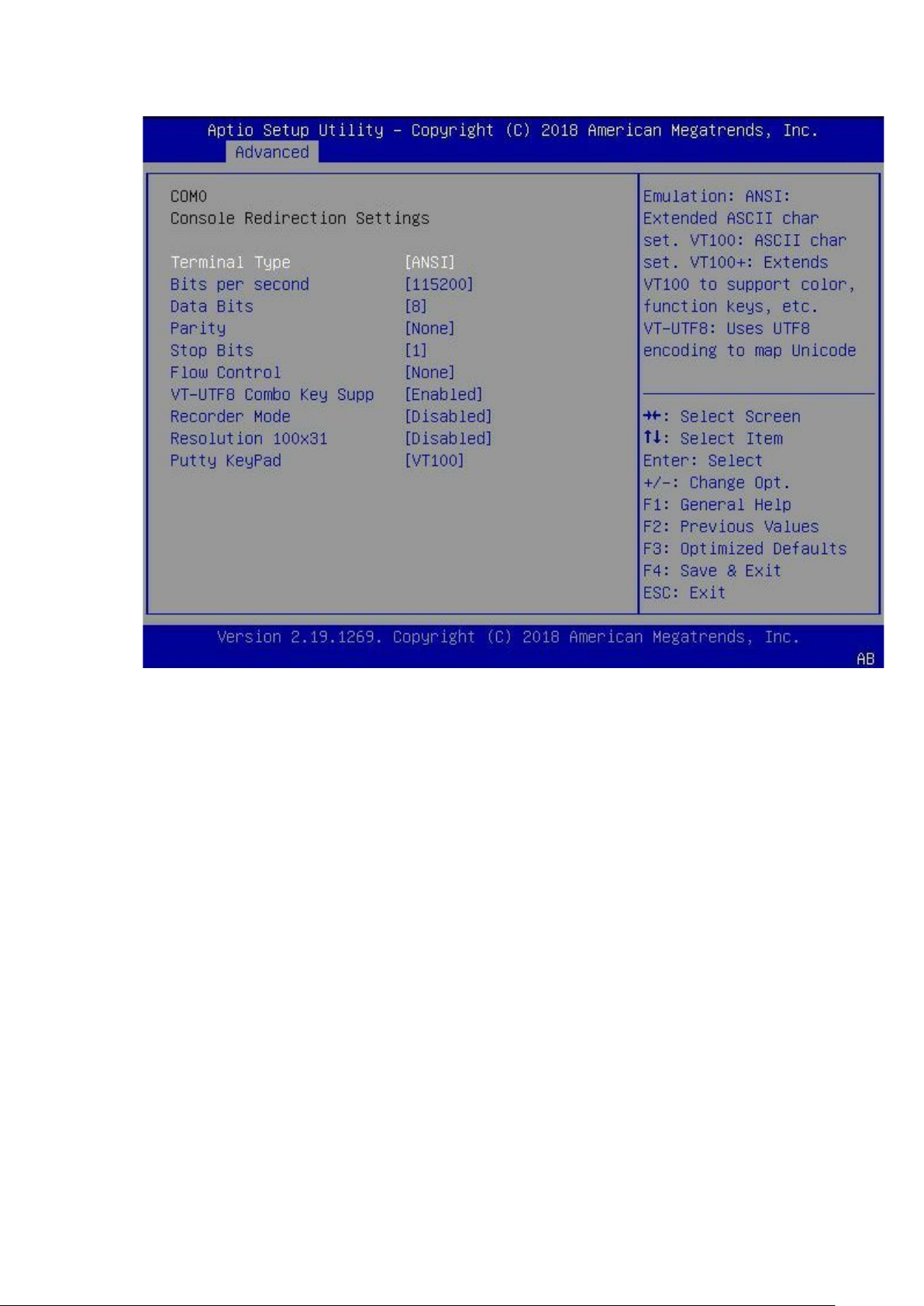
Console Redirection Settings
To open the Console Redirection Settings page, select Advanced Serial Port Console Redirection
Console Redirection Settings from the Aptio Setup Utility.
Terminal Type:
ANSI: Extended ASCII char set.
VT100: ASCII char set.
VT100+: Extends VT100 to support color.
Bits per second: Selects serial port transmission speed. The speed must be matched on the other side.
Long or noisy lines may require lower speeds.
Data Bits: Data Bits
Parity: Sent with the data bits to detect some transmission errors.
Even: parity bit is 0 if the number of 1's in the data bits is even.
Odd: parity bit is 1 if the number of 1's in the data bits is odd.
Stop Bits: Stop bits indicate the end of a serial data packet. (A start bit indicates the beginning). The
standard setting is 1 stop bit.
Flow Control: Prevents data loss from buffer overflow. When sending data.
VT-UTF8 Combo Key Support: Enable VT-UTF8 Combination Key Support for ANSI/VT100 terminals.
Recorder Mode: Enable so that only text is sent. This is used to capture Terminal data.
Resolution 100x31: Ena bles or disables extended terminal resolution
Putty KeyPad: Select FunctionKey and KeyPad on Putty.
13
Page 14
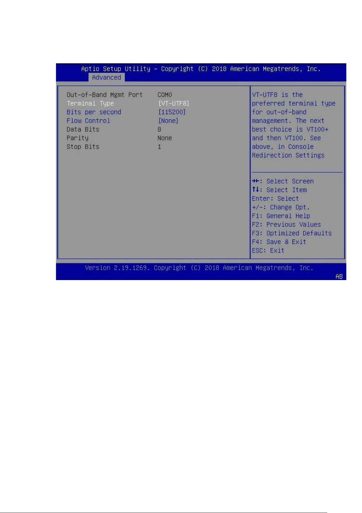
Out-Of-Band Mgmt Port
To open the Out-Of-Band Mgmt Port page, select Advanced Serial Port Console Redirection
Out-Of-Band Mgmt Port from the Aptio Setup Utility.
Out-of-Band Mgmt Port: Microsoft Windows Emergency Management Services (EMS) allows for remote
management of a Windows Server OS through a serial port.
Terminal Type: Default preferred terminal type is VT-UTF8 for out-of-band management. The next best
choice is VT100+ and then VT100.
Bits per second: Selects serial port transmission speed. The speed must be matched on the other side.
Long or noisy lines may require lower speeds.
Flow Control: Prevents data loss from buffer overflow when sending data.
Data Bits: Data Bits
Parity: Sent with the data bits to detect some transmission errors.
Even: parity bit is 0 if the number of 1's in the data bits is even.
Odd: parity bit is 1 if the number of 1's in the data bits is odd.
Stop Bits: Indicates the end of a serial data packet. (A start bit indicates the beginning). The standard
setting is 1 stop bit.
14
Page 15
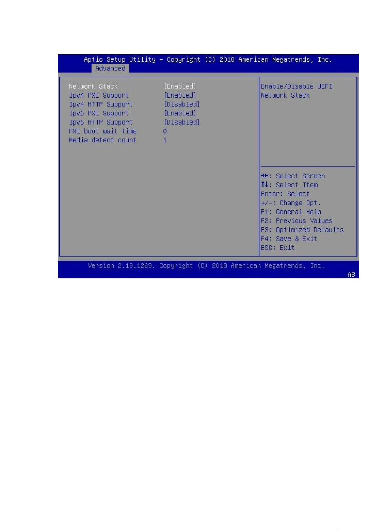
Network Stack Configuration
To open the Network Stack Configuration page, select Advanced Network Stack Configuration from
the Setup.
Network Stack: Enable/Disable UEFI Network Stack
Ipv4 PXE Support: Enable/Disable IPv4 PXE boot support. If disabled
Ipv4 HTTP Support: Enable/Disable IPv4 HTTP boot support. If disabled
Ipv6 PXE Support: Enable/Disable IPv6 PXE boot support. If disabled
Ipv6 HTTP Support: Enable/Disable IPv6 HTTP boot support. If disabled
PXE boot wait time: Wait time in seconds to press ESC key to abort the PXE boot. Use either +/- or
numeric keys to set the value.
Media detect count: Number of times the presence of media is checked. Use either +/- or numeric keys
to set the value.
15
Page 16
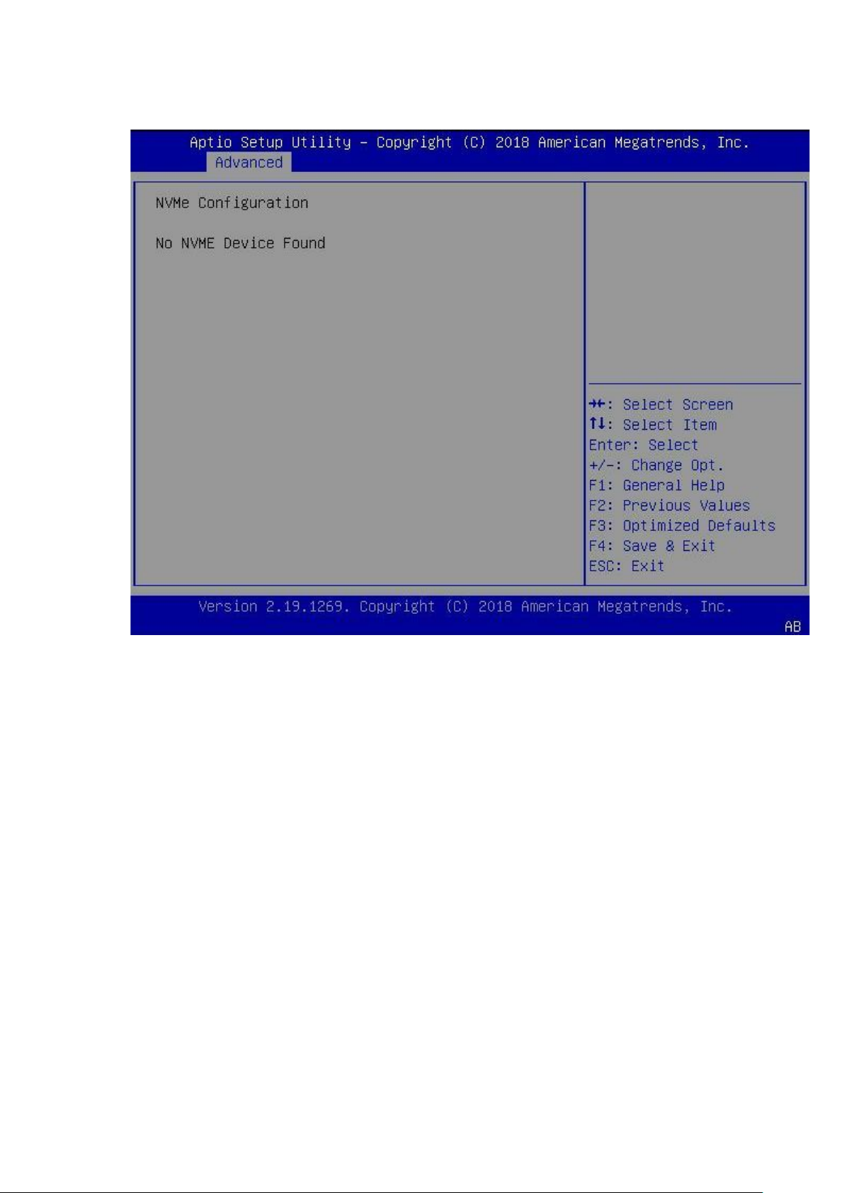
NVMe Configuration
To open the NVMe Configuration page, select Advanced NVMe Configuration from the Setup.
16
Page 17
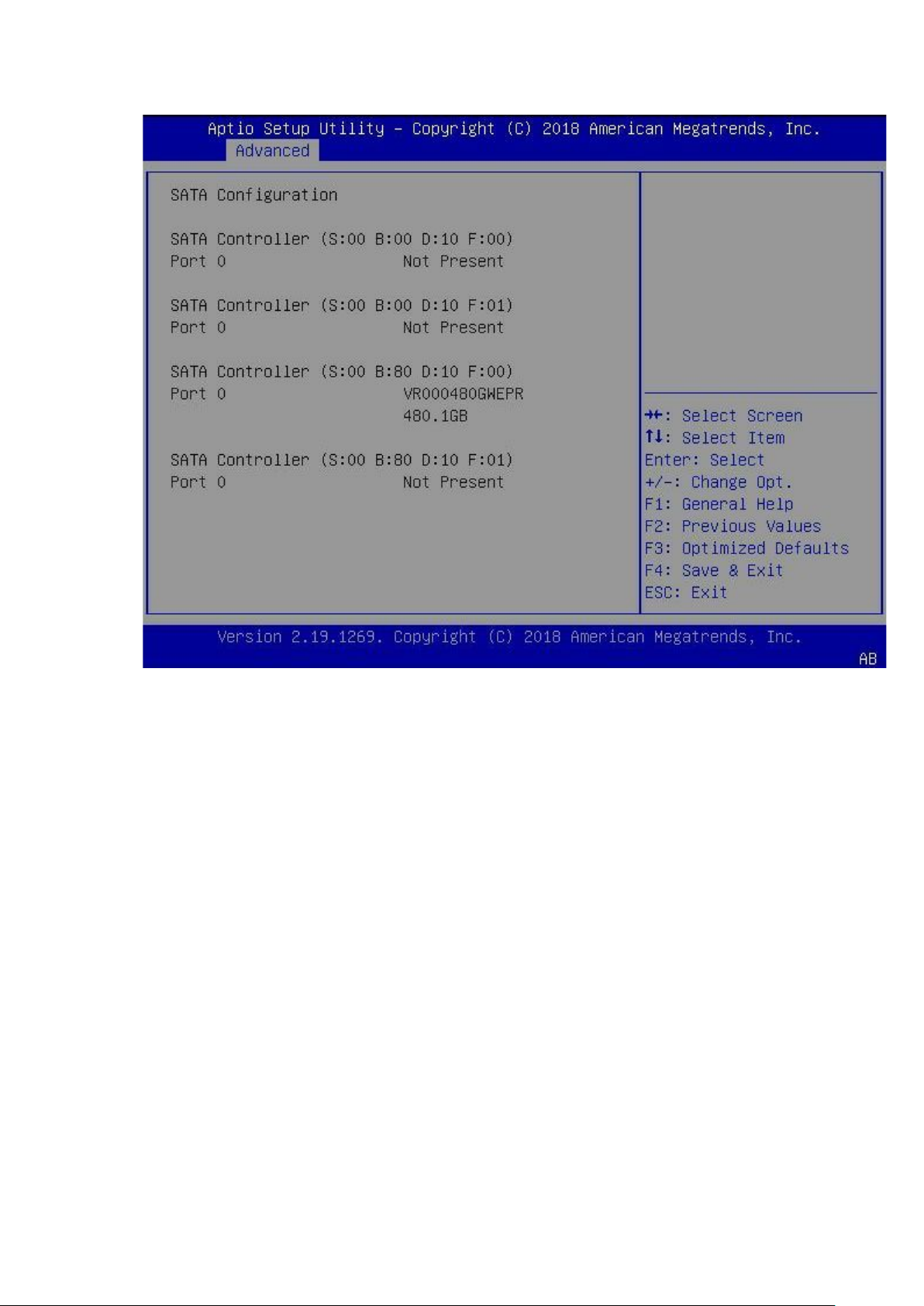
SATA Configuration
To open the SATA Configuration page, select Advanced SATA Configuration from the Setup.
17
Page 18
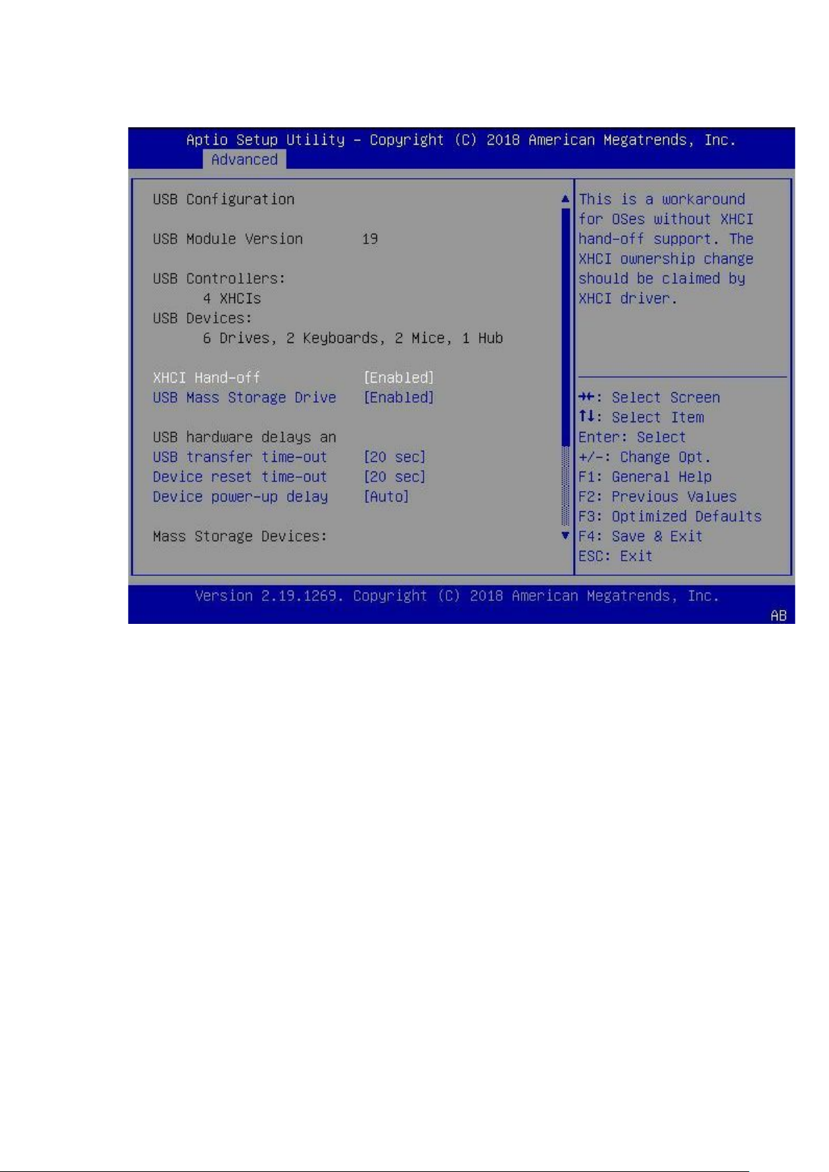
USB Configuration
To open the USB Configuration page, select Advanced USB Configuration from the Setup.
USB Module Version: Display USB module version.
USB Controllers: 4 XHCIs
USB Devices: Display USB device.
XHCI Hand-off: This is a workaround for OSes without XHCI hand-off support. The XHCI ownership
change should be claimed by XHCI driver.
USB Mass Storage Driver: Enable/Disable USB Mass Storage Driver Support.
USB hardware delays and time-outs:
USB transfer time-out: The time-out value for Control
Device reset time-out: USB mass storage device Start Unit command time-out.
Device power-up delay: Maximum time the device will take before it properly reports itself to the Host
Controller. 'Auto' uses default value: for a Root Device power-up delay in seconds Delay range is 1..40
seconds.
Mass Storage Devices: Mass storage device emulation type. 'AUTO' enumerates devices according to
their media format. Optical drives are emulated as 'CDROM'
18
Page 19
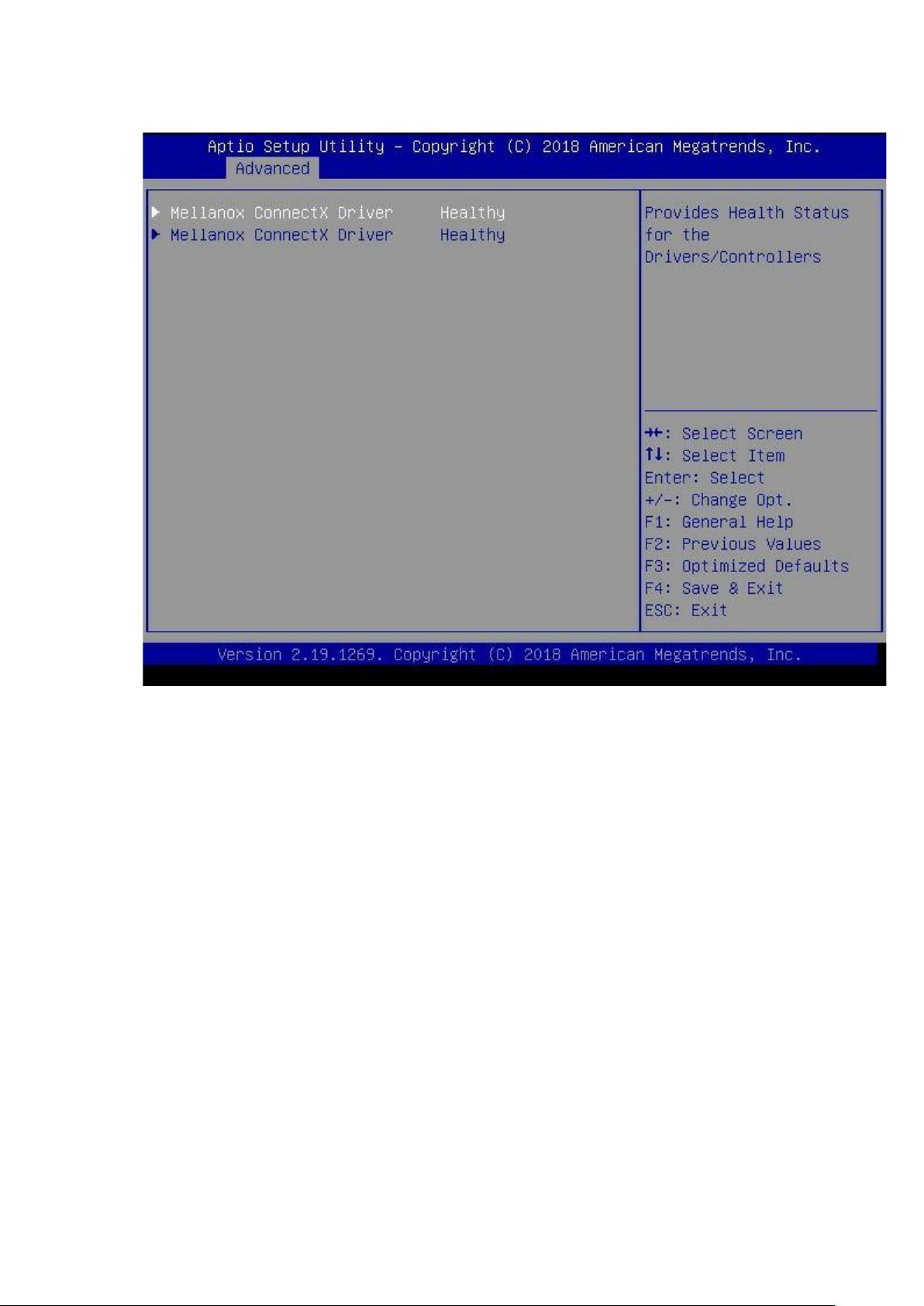
Driver Health
Driver Health page provides Health Status for the Drivers/Controllers. To open the Driver Health page,
select Advanced
Driver Health from the Setup.
19
Page 20
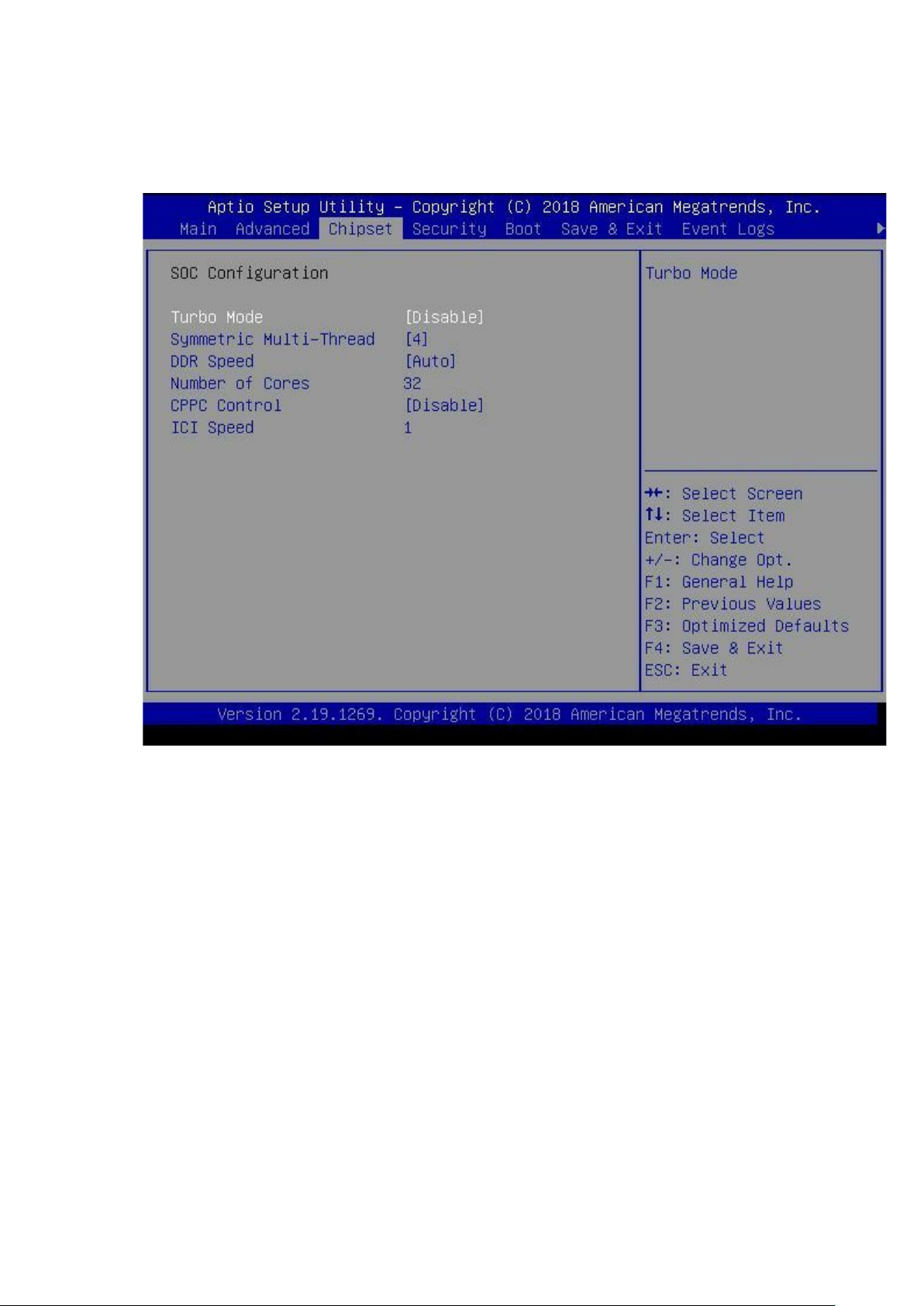
Chipset
The Chipset option configures the SOC parameter. The Chipset page shows information such as Turbo Mode,
Symmetric Multi-Thread, DDR speed, Number of Cores, CPPC control, and ICI Speed of the SOC.
To open the Chipset page, select Chipset from the Setup.
SOC Configuration
Turbo Mode: Enable/Disable Turbo Mode.
Symmetric Multi-Threading: Select symmetric multi-threading.
DDR Speed: Select DDR Speed.
Number of Cores: Select CPU core number. The range is 1 - 32
CPPC Control: Enable/Disable CPPC Control.
ICI Speed: The range is 1 - 32
20
Page 21
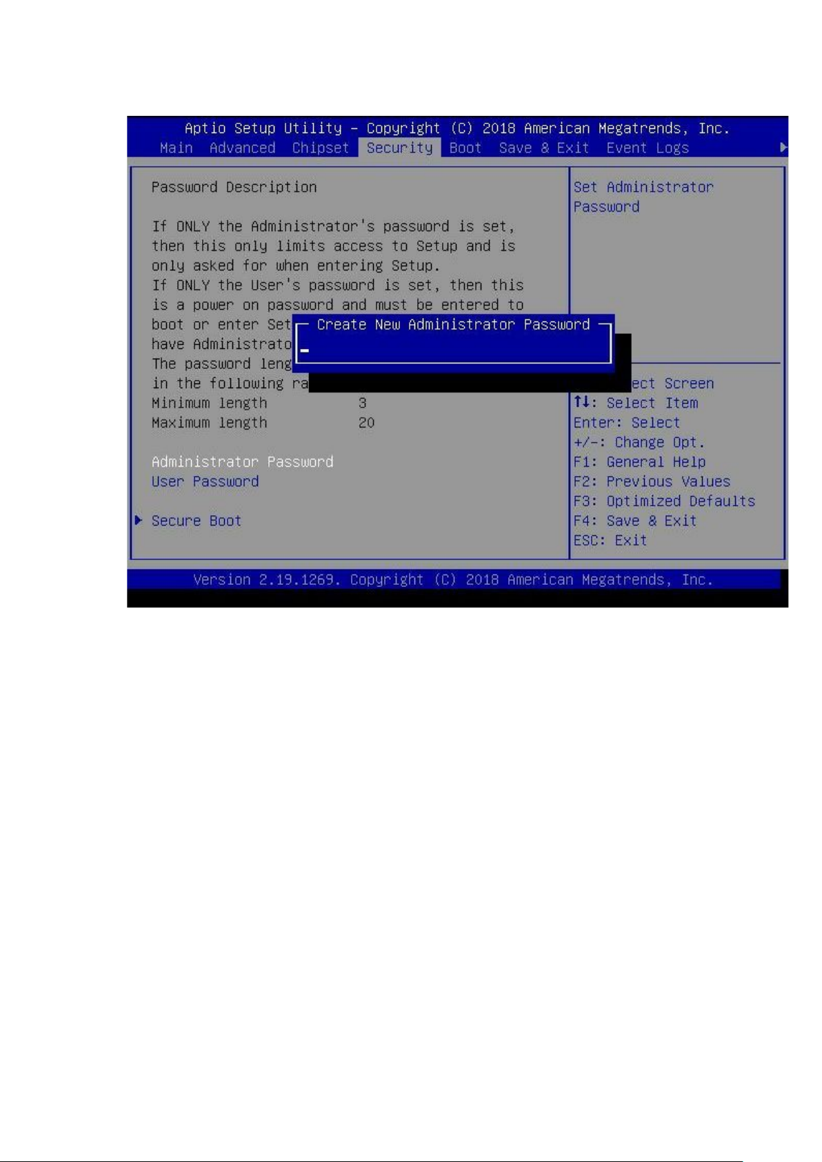
Security
To open the Security page, select Security from the Setup.
Administrator Password: Set Administrator Password
User Password: Set User Password
21
Page 22
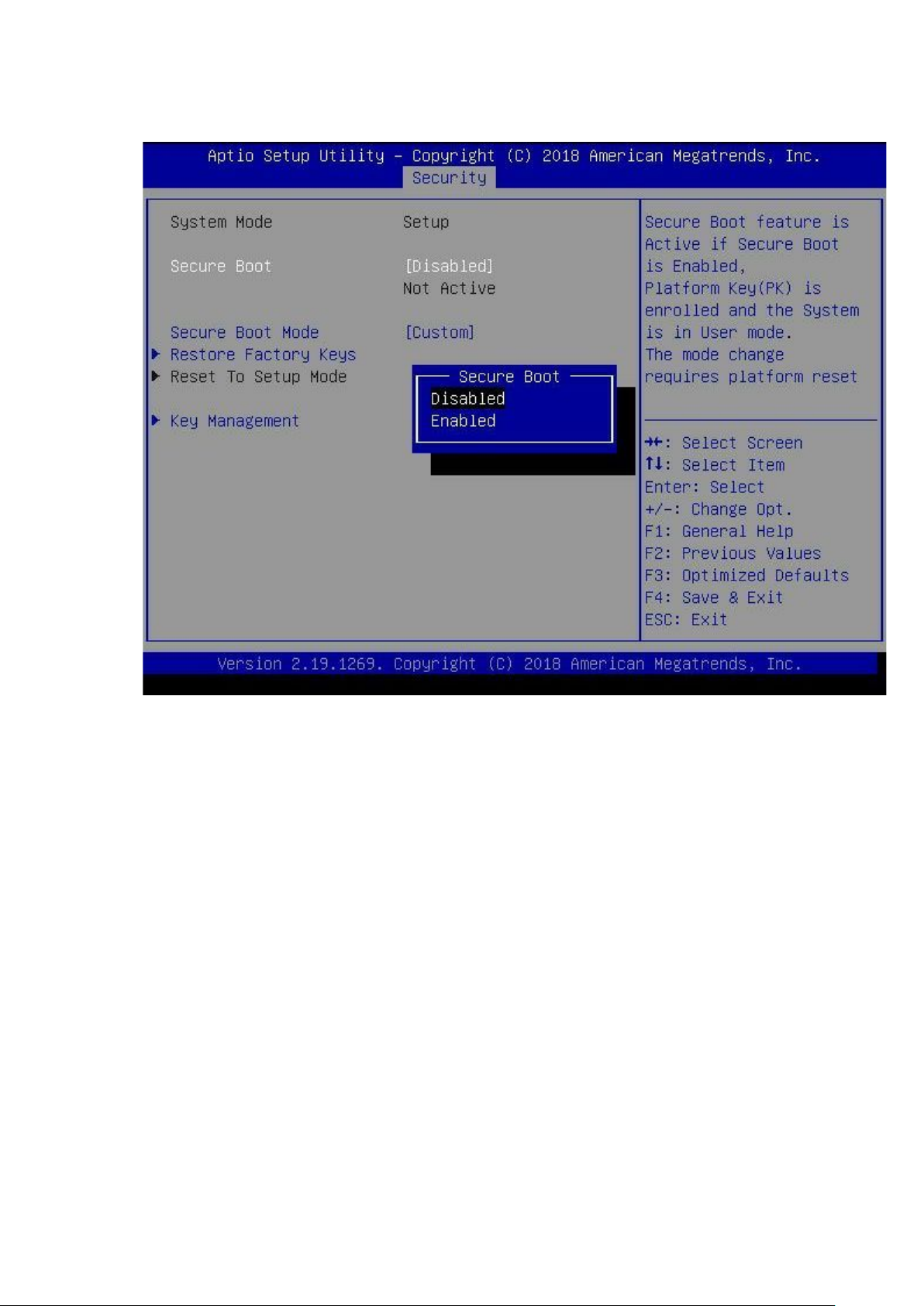
Secure Boot
To open the Secure Boot page, select Security Secure Boot from the Setup.
System Mode
Secure Boot: Secure Boot f eatur e is Active if Secure Boot is Enabled
Secure Boot Mode: Secure Boot mode options: Standard or Custom. In Custom mode
Restore Factory Keys: Force System to User Mode. Install factory default Secure Boot key databases
Reset To Setup Mode: Delete all Secure Boot key databases from NVRAM
22
Page 23
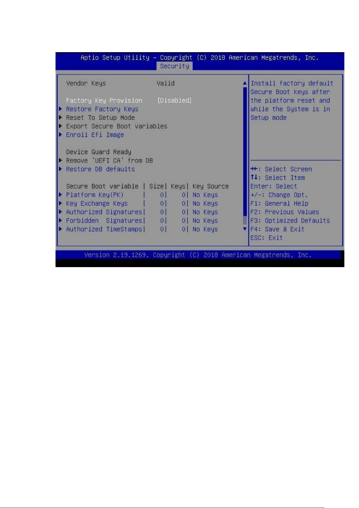
Key Management
To open the Key Management page, select Security Secure Boot Key Management from the
Setup. This function enables expert users to modify Secure Boot Policy variables without full
authentication.
Factory Key Provision: Install factory default Secure Boot keys after the platform reset while the System
is in Setup mode.
Restore Factory Keys: Force System to User Mode and restores Install factory default Secure Boot key
databases.
Reset To Setup Mode: Deletes all Secure Boot key databases from NVRAM.
Export Secure Boot variables: Copies NVRAM content of Secure Boot variables to files in a root folder
on a file system device
Enroll Efi Image: Allows the image to run in Secure Boot mode and enrolls the SHA256 Hash certificate
of a PE image into Authorized Signature Database (db).
Device Guard Ready
Remove 'UEFI CA' from DB: Removes the ‘Microsoft UEFI CA’ certificate in the Authorized Signature
database when in Device Guird Ready mode.
Restore DB defaults: Restores DB variable to factory defaults.
Secure Boot variable: Enrolls Factory Defaults or load certificates from a file.
1. Public Key Certificate:
a. EFI_SIGNATURE_LIST
b. EFI_CERT_X509 (DER)
c. EFI_CERT_RSA20
23
Page 24
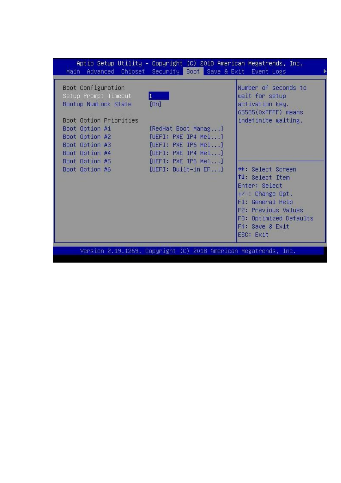
Boot
To open the Boot page, select Boot from the Setup.
.
Boot Configuration
Setup Prompt Timeout: Number of seconds to wait for setup activation key. 65535(0xFFFF) means
indefinite waiting.
Bootup NumLock State: Select the keyboard NumLock state
24
Page 25
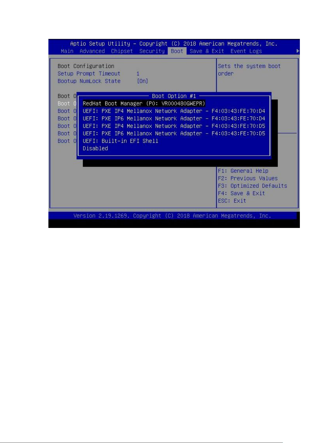
Boot Option Priorities
Sets the system boot order
25
Page 26
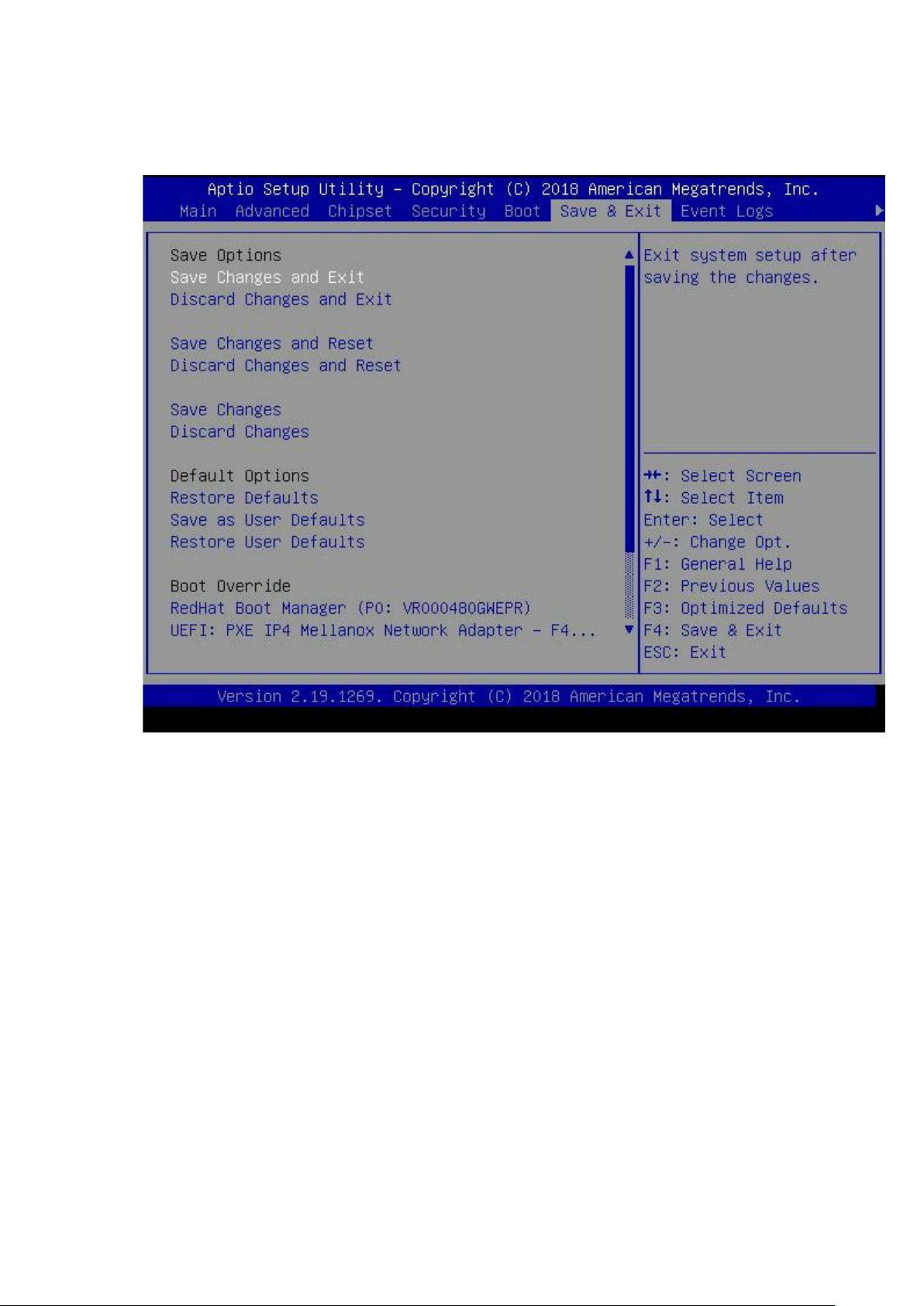
Save & Exit
When the BIOS configuration is complete, save the changes and exit or discard changes and exit. To
open the Save & Exit page, select Save & Exit from the Setup.
Save Options
Save Changes and Exit: Exits the system setup after saving the changes.
Discard Changes and Exit: Exits the system setup without saving any changes.
Save Changes and Reset: Resets the system after saving the changes.
Discard Changes and Reset: Resets the system setup without saving any changes.
Save Changes: Saves the changes done so far to any of the setup options.
Discard Changes: Discard the changes done so far to any of the setup options.
Default Options
Restore Defaults: Restores or loads default values for all the setup options.
Save as User Defaults: Saves the changes made for User Defaults.
Restore User Defaults: Restores the User Defaults for all the setup options.
Boot Override
The option overrides boot selection.
26
Page 27
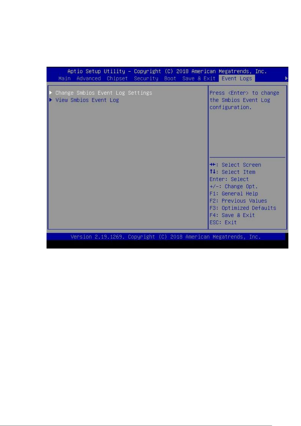
Event Logs
The Event Logs page displays the following information.
Change Smbios Event Log Settings
View Smbios Event LogSerial Port Console Redirection
To open the Event Logs page, select Event Logs from the Setup.
27
Page 28
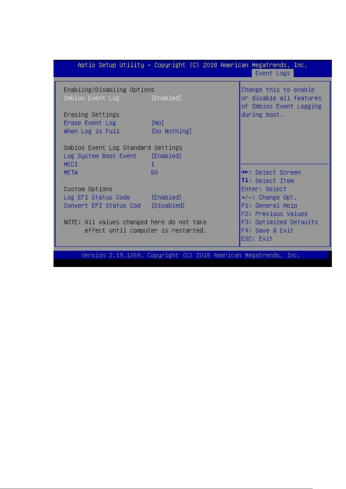
Change Smbios Event Log Settings
To open the Change Smbios Event Log Setting page, select Event Logs Change Smbios Event Log
Setting from the Setup.
Enabling/Disabling Options
Smbios Event Log: Enables or disables all features of Smbios Event Logging during boot.
Erasing Settings
Erase Event Log: Select options to erase the Smbios Event Log. Erasing is done prior to any logging
activation during reset.
When Log is Full: Select options for reactions to a full Smbios Event Log.
Smbios Event Log Standard Settings
Log System Boot Event: Enable or disable logging the System boot event
Multiple Event Count Increment (MECI): The number of occurrences of a duplicate event that must
happen before the multiple-event counter of log entry is updated.
Multiple Event Time Window (METW): The number of minutes which must happen between duplicate
log entries which utilize a multiple-event counter. The value ranges from 0 to 99 minutes
Custom Options
Log EFI Status Code: Enable or disable logging the EFI Status Codes as OEM reserved type E0 (if not
already converted to legacy).
Convert EFI Status Codes to Standard Smbi os Type: Enable or disable converting the EFI Status
Codes to Standard Smbios Types (Not all may be translate).
NOTE:
All values changed here do not take effect until computer is restarted.
28
Page 29
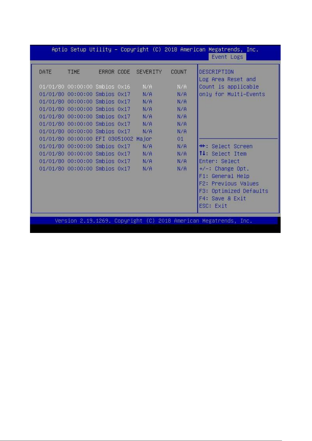
View Smbios Event Log
To open the View Smbios Event Log Setting page, select Event Logs View Smbios Event Log from
the Setup. This page displays the list of event logs occurred by Smbios on this platform.
29
Page 30
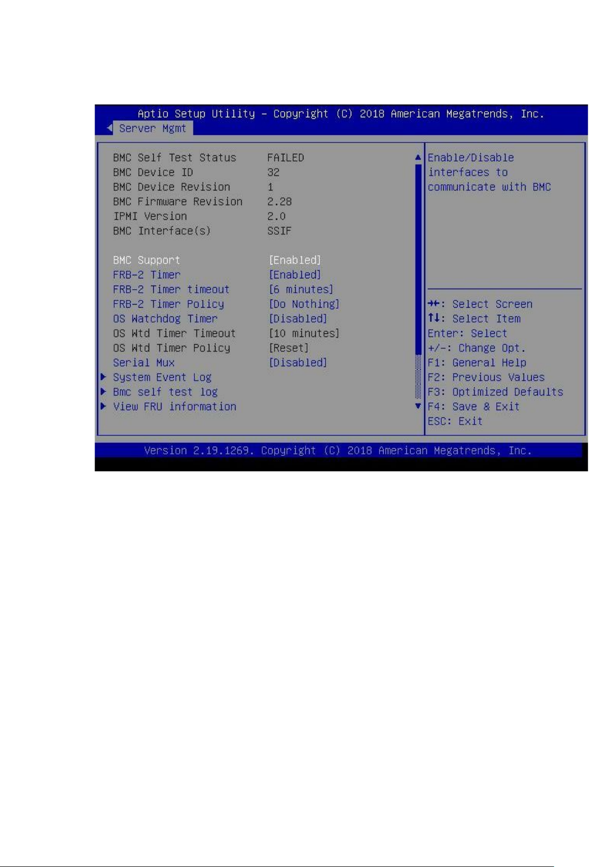
Server Mgmt
To open the Server Mgmt page, select Server Mgmt from the Step.
BMC Self Test Status: Displays self-test status.
BMC Device ID: Disp lays BMC device ID.
BMC Device Revision: Displays BMC device revision.
BMC Firmware Revision: Displays BMC firmware revision.
IPMI Version: Displays IPMI version
BMC Interface(s) : Displays BMC interface.
BMC Support: Enables or Disables interfaces to communicate with BMC.
FRB-2 Timer: Enables or Disables FRB-2 timer (POST timer).
FRB-2 Timer timeout: Allows a value between 3 to 6 min for FRB-2 Timer Expiration value.
FRB-2 Timer Policy: Configure how the system should respond if the FRB-2 Timer expires. Not available
if FRB-2 Timer is disabled.
OS Watchdog Timer: If enabled
OS Wtd Timer Timeout: Configure the length of the OS Boot Watchdog Timer. Not available if OS Boot
Watchdog Timer is disabled.
OS Wtd Timer Policy: Configure how the system should respond if the OS Boot Watchdog Timer expires.
Not available if OS Boot Watchdog Timer is disabled.
Serial Mux: Enables or disables Serial Mux configuration.
System Event Log: Changes the SEL event log configuration.
View FRU information: Views FRU information.
BMC network configuration: Configure BMC network parameters
View System Event Log: Press <Enter> to view the System Event Log Records.
BMC User Settings: Press <Enter> to Add.
BMC Warm Reset: Do warm reset BMC.
30
Page 31
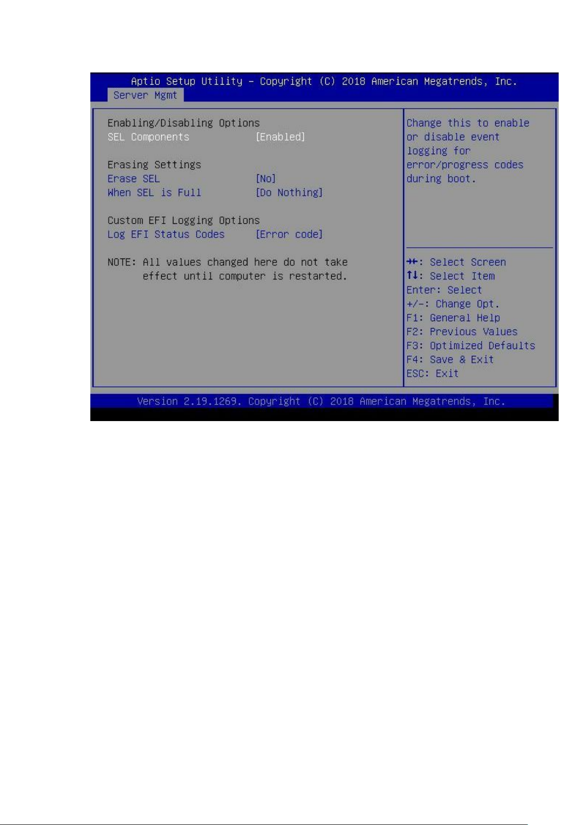
System Event L og
To open the System Event Log page, select Server Mgmt System Event Log from the Step.
Enabling/Disabling Options
SEL Components: Change this to enable or disable event logging for error/progress codes during boot.
Erasing Settings
Erase SEL: Select options for erasing SEL.
When SEL is Full: Select options for reactions to a full SEL.
Custom EFI Logging Options
Log EFI Status Codes: Disable the logging of EFI Status Codes or logging only the error code or the
progress code or both.
NOTE:
All values changed here do not take effect until computer is restarted.
31
Page 32
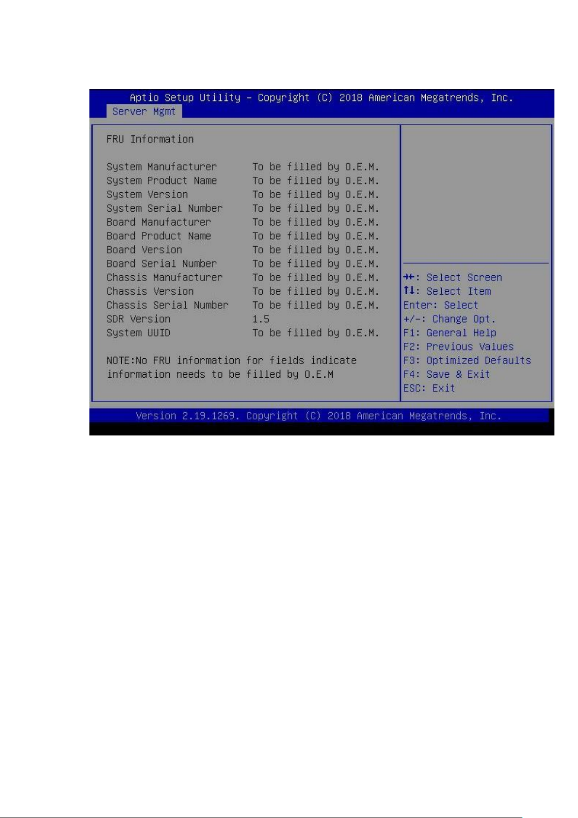
View FRU information
To open the View FRU information page, select Server Mgmt View FRU information from the Step.
32
Page 33
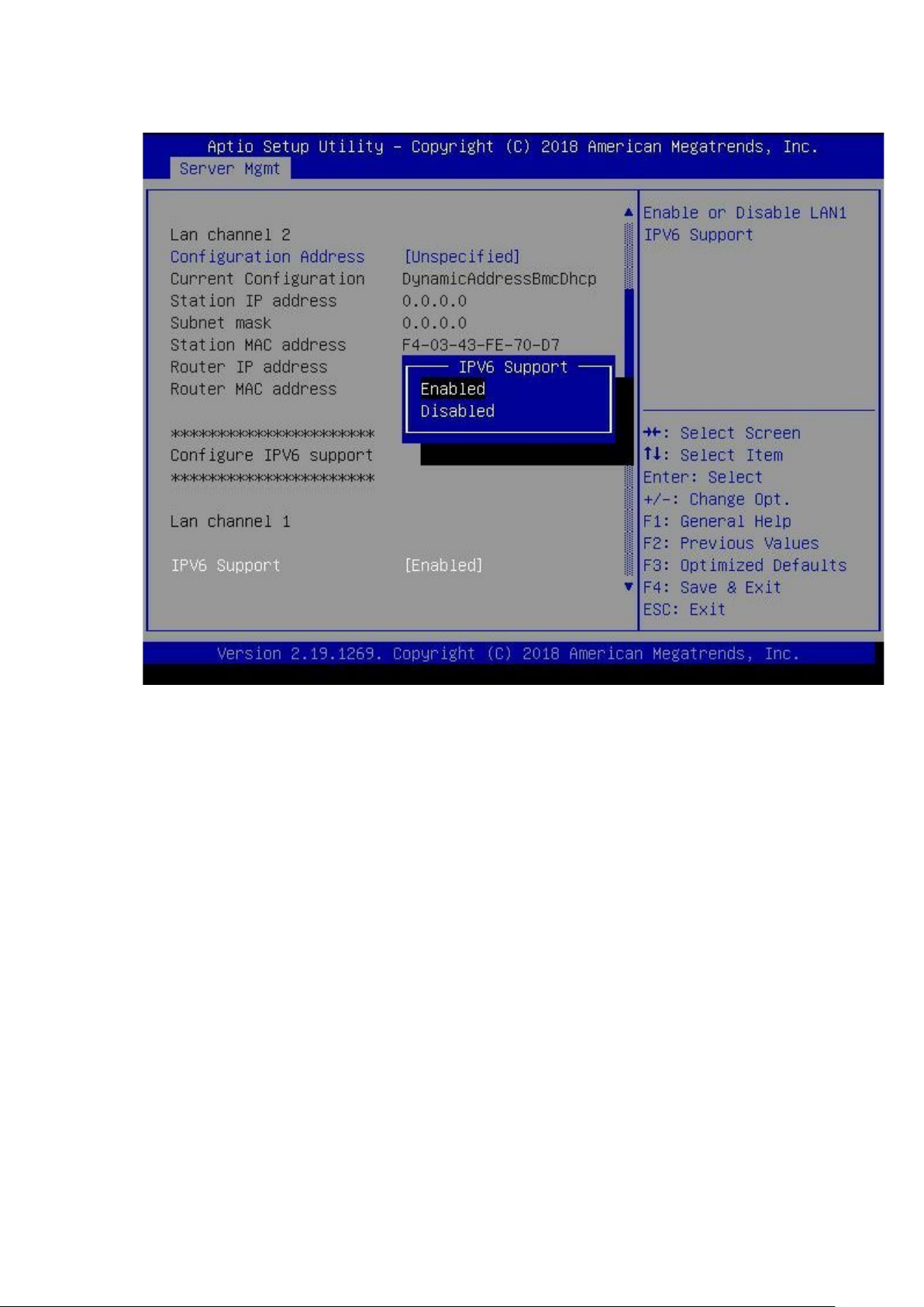
BMC network configur ation
To open the BMC network configuration page, select Server Mgmt BMC network configuration from
the Step.
Configure IPV4 support
Configuration Address source: Configure LAN channel parameters statically or dynamically (by
BIOS or BMC). Unspecified option will not modify an
Current Configuration Address source: Configuration for the current LAN either statically or
dynamically (by BIOS or BMC). Unspecified for not Configured address space
Station IP address: Station IP address from BMC
Subnet mask: Subnet mask from BMC
Station MAC address: Station MAC address from BMC
Router IP address: Router IP address from BMC
Router MAC address: Router MAC address from BMC
Configure IPV6 support
Configuration Address source: Select to configure LAN channel parameters statically or
dynamically (by BIOS or BMC). Unspecified option will not modify an
Current Configuration Address source: Current Ipv6 LAN Configuration statically or dynamically
(by BMC). Unspecified for not Configured address space.
Station IPV6 address: Station IPV6 address from BMC
Prefix Length:
IPV6 Router1 IP Address: Station IPV6 router address from BMC
IPV6 address status: Status of station IPV6 address to BMC.
IPV6 DHCP Algorithm: Providing the DHCP method used like DHCPv6 or StateLess Address Auto
Configuration (SLAAC).
Note:
IPV6 is not supported in BMC (OR). IPV6 support is disabled.
33
Page 34
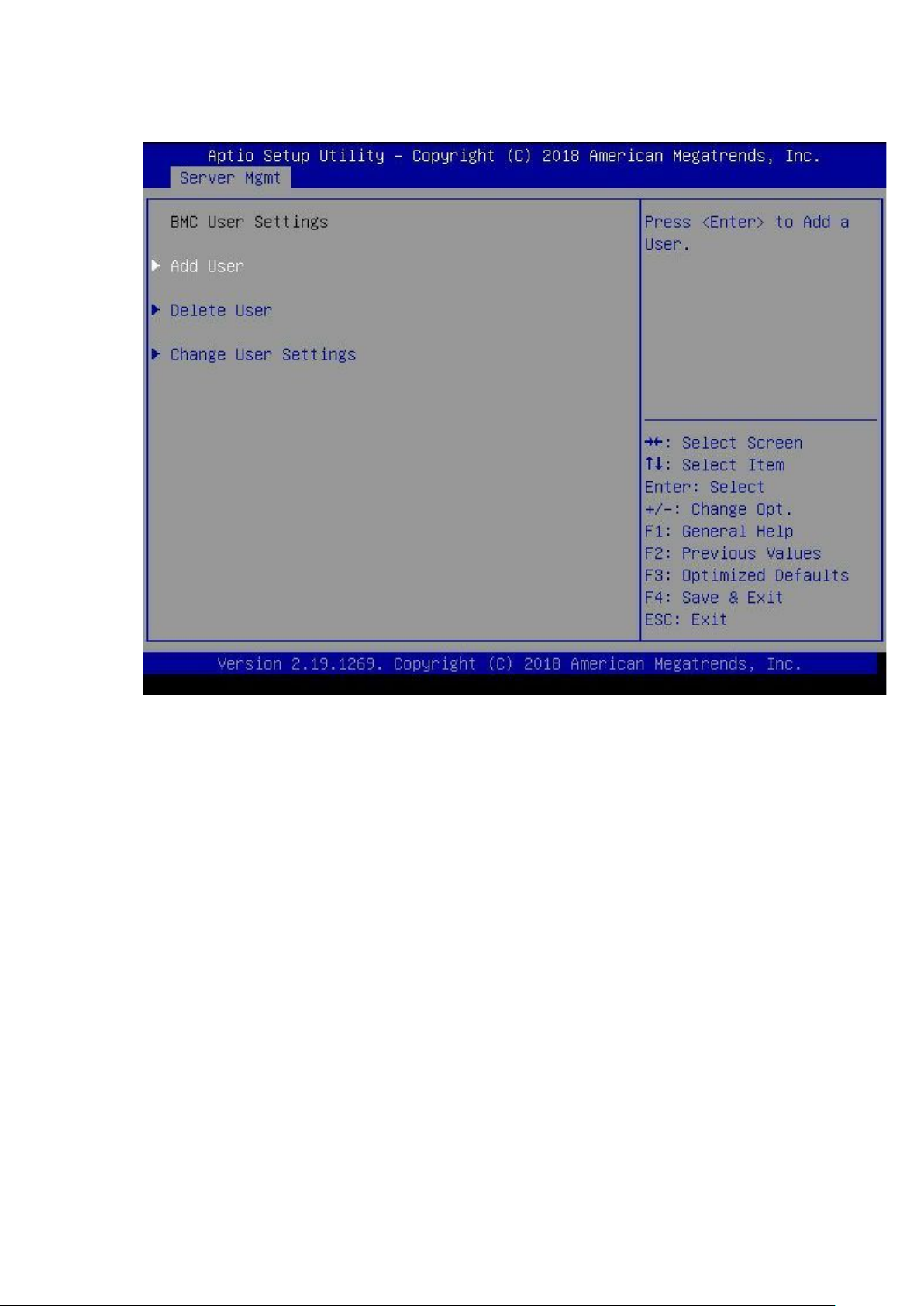
BMC User Settings
To open the BMC User Settings page, select Server Mgmt BMC User Settings from the Step.
Add User: Add a User.
Delete User: Delete a User.
Change User Settings: Change User Settings.
34
Page 35
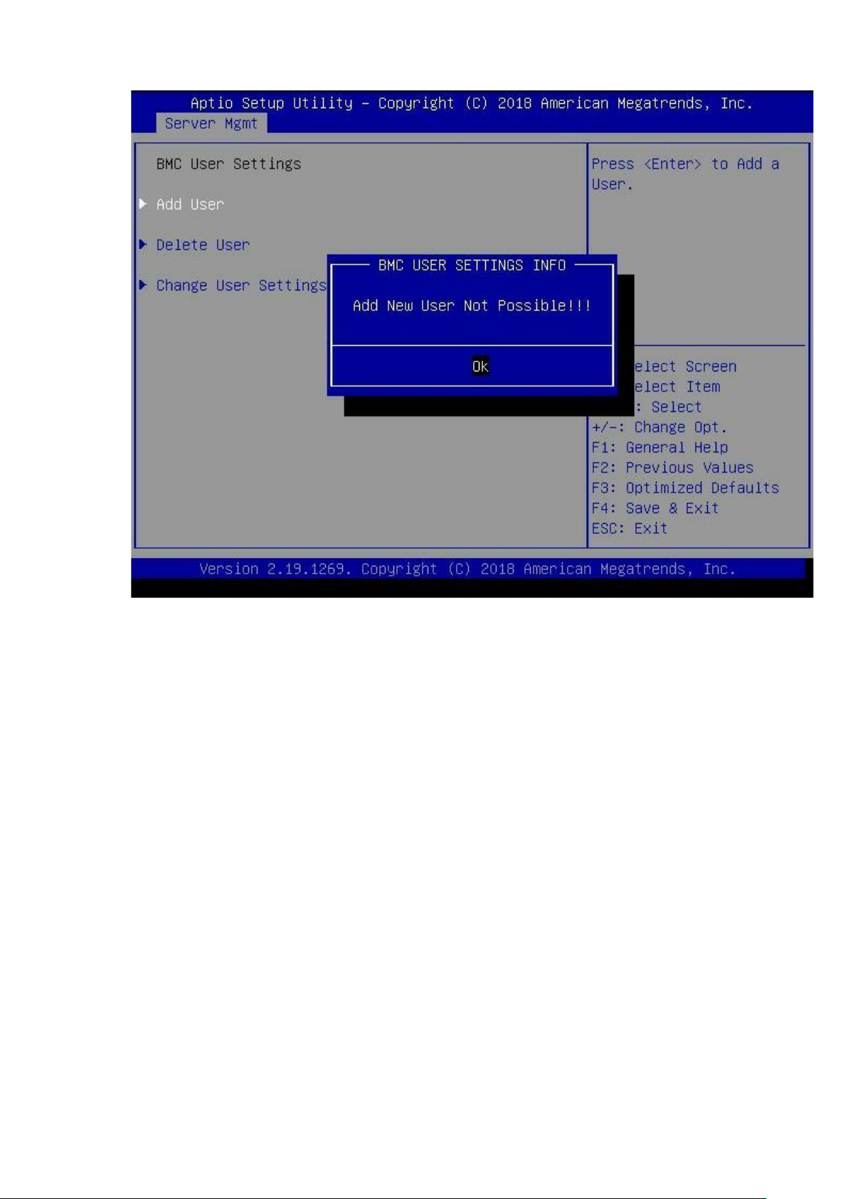
Add User
To open the Add User page, select Server Mgmt BMC User Settings Add User from the Step.
User Name: Enter BMC User Name.
User Password: Enter BMC User Password.
User Access: Enable/Disable the BMC User's Access.
Channel No: Enter BMC Channel Number.
User Privilege Limit: Enter BMC User Privilege Limit for Selected Channel.
35
Page 36
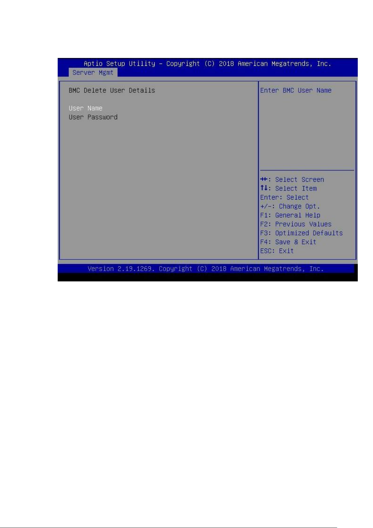
Delete User
To open the Delete User page, select Server Mgmt BMC User Settings Delete User from the
Step.
User Name: Enter BMC User Name.
36
Page 37
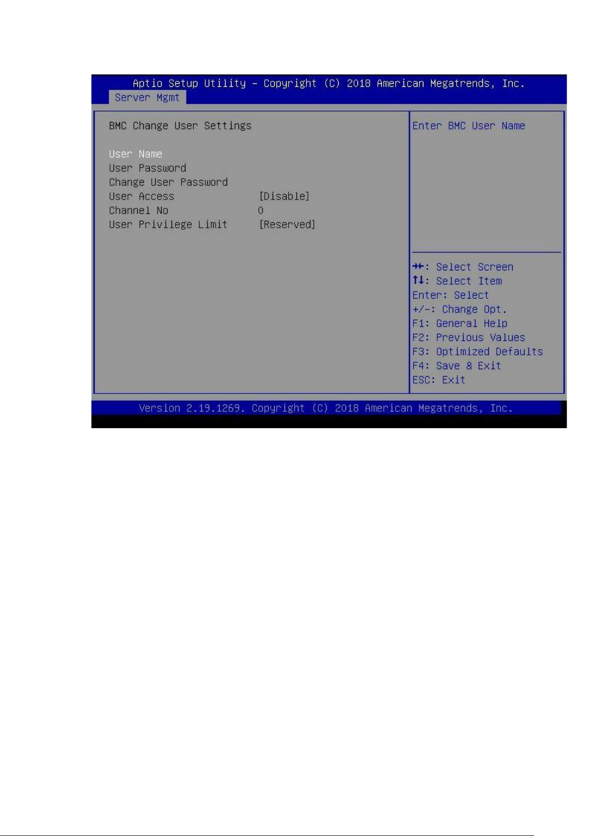
Change User Settings
To open the Change User Settings, select Server Mgmt BMC User Settings Change User
Settings from the Step.
User Name: Enter BMC User Name.
Change User Password: Enter New Password to change.
User Access: Enable/Disable the BMC User's Access.
Channel No: Enter BMC Channel Number.
User Privilege Limit: Enter BMC User Privilege Limit for Selected Channel.
37
 Loading...