

Page 1

Apollo 480 Hardware User Guide
Abstract
This document provides an overview of the main features of the HPE Apollo 480 Cluster
platform, which is a custom configured, high performance, compute server that features highdensity computing.
Part Number: P11204-001
Published: 09 2018
Edition: 001
Page 2

©
Copyright 2018, Hewlett Packard Enterprise Development LP
Notices
The information contained herein is subject to change without notice. The only warranties for Hewlett
Packard Enterprise products and services are set forth in the express warranty statements accompanying
such products and services. Nothing herein should be construed as constituting an additional warranty.
Hewlett Packard Enterprise shall not be liable for technical or editorial errors or omissions contained
herein.
Confidential computer software. Valid license from Hewlett Packard Enterprise required for possession,
use, or copying. Consistent with FAR 12.211 and 12.212, Commercial Computer Software, Computer
Software Documentation, and Technical Data for Commercial Items are licensed to the U.S. Government
under vendor's standard commercial license.
Links to third-party websites take you outside the Hewlett Packard Enterprise website. Hewlett Packard
Enterprise has no control over and is not responsible for information outside the Hewlett Packard
Enterprise website.
Acknowledgments
Intel®, Itanium®, Pentium®, Intel Inside®, and the Intel Inside logo are trademarks of Intel Corporation in
the United States and other countries.
Microsoft® and Windows® are either registered trademarks or trademarks of Microsoft Corporation in the
United States and/or other countries.
Adobe® and Acrobat® are trademarks of Adobe Systems Incorporated.
Java® and Oracle® are registered trademarks of Oracle and/or its affiliates.
UNIX® is a registered trademark of The Open Group.
Page 3

Contents
Product Overview....................................................................................4
System Operation and Troubleshooting...............................................9
Technical Specifications...................................................................... 14
Regulatory Overview............................................................................ 15
Websites................................................................................................ 16
Support and other resources...............................................................17
Accessing Hewlett Packard Enterprise Support......................................................................... 17
Accessing updates......................................................................................................................17
Customer self repair....................................................................................................................18
Remote support.......................................................................................................................... 18
Warranty information...................................................................................................................18
Regulatory information................................................................................................................19
Documentation feedback............................................................................................................ 19
3
Page 4

Product Overview
This chapter provides an overview of the main features of the HPE Apollo 480 Cluster platform. The
Apollo 480 Cluster is a custom configured, high performance, compute server that features high-density
computing, up to 80 processors per rack. Each rack can support up to 10 enclosures. Each enclosure will
have redundant power supplies and support either two or four independent nodes within a compute tray.
The last section of this chapter describes operating precautions. Before operating your system, familiarize
yourself with the safety information in that section.
System Features
This section describes the flexible architecture and technical features of the HPE Apollo 480 platform in
the following sections:
HPE Apollo 480 Cabinet (Rack)
The HPE Apollo 480 cabinet is a standalone 42U rack. The 42U rack can hold a variable amount of
compute, up to 40 nodes. An optional top-mounted extension is available to add room for switches or
optional full-width equipment.
Figure 1: Apollo 480 Cluster Cabinet Example
An optional 2U head node spans the width of the rack interior, see the subsection Optional IO Servers
for additional detail. The cabinet’s 24” x 48” footprint approximates that of standard floor tiles and an
optional 3U extension is available for additional head nodes, networking, or ATS equipment.
Hadoop Specialized Rack Option:
The Apollo 480 system can be optionally specialized for Hadoop Reference Implementation (RI) usage.
This version of the rack allocates 36U of space in the lower section of the cabinet. It is configured with
Apollo 480 compute enclosures. A 2U space is reserved for switch installation. The remaining 4U of
space (U39 through U42) is used for the installation of 1U full-width (full-depth) nodes. Only one Hadoop
RI rack is used in each Hadoop cluster configuration.
4 Product Overview
Page 5

Compute Trays
Each Apollo 480 compute tray can support two or four multiprocessor-based node boards (server
boards). The Apollo 480 Cluster node server boards documented in this guide are based on Intel
chipsets. The compute nodes also house hard drives, graphics or I/O options, as well as fans.
NOTE: Customers requiring AMD™ clusters can check with an HPE sales or service representative for
information on non-Apollo 480 AMD-based cluster offerings available from HPE.
As stated earlier, the Apollo 480 Cluster rack architecture supports up to 40 compute nodes (36 nodes in
a Hadoop RI rack), along with the following features:
• Ability to use a 1U standard-depth head node (multiple nodes in Hadoop configuration);
• Individual node serviceability.
Figure 2: Compute Node Example
Processors
The Apollo 480 Cluster can support the following configuration of processors: 42U-system minimum, with
two processors for each node.
The exact type of processors provided with your system depends on the specific configuration you
ordered. Check with your sales or service representative for information on processor availability,
upgrades, and compatibility. The HPE Apollo 480 Cluster platform uses two Intel Xeon Silver/Gold
(Skylake) processors per motherboard.
Product Overview 5
Page 6

Figure 3: Example Apollo 480 Motherboard diagram
DIMM Memory
Memory configuration varies depending on the processor board type ordered with your compute nodes.
DIMM population requirements are 12 per server board and standard DIMM speeds are 2,400 MHz. Use
of more than one DIMM per channel will result in the processor operating that channel at 1,600 MHz by
default regardless of the DIMM operational capacity.
Power Supplies
The Apollo 480 Cluster uses two high-efficiency power supplies per enclosure. Depending on your system
configuration and input voltage, each power supply provides a maximum of 2000W of power to the
enclosure.
NOTE: The Apollo 480 power supplies are not installed in the compute trays, but instead alongside the
trays within the rack.
CAUTION: The cabinet power supply cord is used as the main disconnect device. Ensure that a
socket outlet is located or installed near the equipment and is easily accessible.
6 Product Overview
Page 7
Compute Tray Drive Subsystem
Apollo 480 was designed to support SATA or SAS hard disk drives. Each compute tray connects to a front
enclosure that can support up to 48 drives. One rack can support up to 10 enclosures. The Apollo 480
standard nodes only support SATA disk drives. However, by adding an optional SAS HBA, certain
versions of the compute nodes can support SAS disk drives. The disk drives installed in the rear of the
compute nodes support software and hardware RAID 0 and 1 only. The disk drives in the front bay are
capable of supporting software RAID 0, 1, 5, 6, and 10 and hardware RAID 0, 1, 5, and 10.
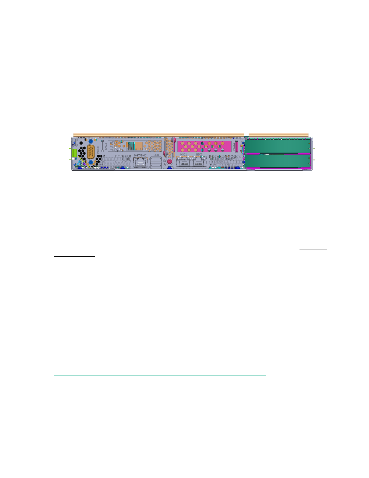
Compute Tray Rear I/O Panel
Each compute node installs through the rear of the Apollo 480 cabinet. The I/O panels typically provide
COM ports, status LEDs, and Ethernet ports.
Figure 4: Compute Node Rear Panel Example
Cooling System
The hardware architecture of both the compute nodes and the racks provide for optimal front-to-back
cooling. Each compute node has an enclosed fan set. Apollo 480 compute node uses four 40mm fan
assemblies each. A sensor on the main board can increase or decrease the fan speed based on the
ambient conditions. Maximum operational ambient air temperature is +35ºC (95ºF). See the Technical
Specifications for more environmental information.
Optional Hardware
Also, the Apollo 480 enclosure and the compute nodes can include various other hardware components
as part of your Apollo 480 configuration as noted following:
• SATA accessories:
◦ A minimum of one disk drive (per tray) is required for operation
◦ One (1) internal SATA port per compute node
◦ One (1) SATA cable set per compute node
• SAS hard drive options
• One or 2 Gbit Ethernet or (optional) InfiniBand switches
NOTE: Apollo 480 Hadoop clusters do not offer optional InfiniBand connectivity.
Admin Node Server
The HPE DL380 system is a compute-optimized head node server comprised of two main subsystems:
the 2U chassis and a server board (motherboard). Check with your sales or service representative before
loading any operating system on your server not provided by the HPE factory or service organization.
Product Overview 7
Page 8
Various hardware components may be included as part of your HPE DL380 system. For more
information, see HPE ProLiant DL380 Gen10 Server User Guide (http://www.hpe.com/info/dl380gen10-
docs).
Optional IO Servers
Optional HPE DL360 and DL380 servers can be configured as Hadoop-specific nodes, including
NameNode, Application Node, and Job Tracker. Check with your sales or service representative before
loading any operating system on your server not provided by the HPE factory or service organization.
Various hardware components may be included as part of your HPE DL360 or DL380 servers. For more
information, see HPE ProLiant DL380 Gen10 Server User Guide (http://www.hpe.com/info/dl380gen10-
docs) or HPE ProLiant DL360 Gen10 Server User Guide (http://www.hpe.com/info/dl360gen10-docs).
Operating System Support
At time of publication, the operating system tested and installed by HPE is CentOS 7. HPE installs and
verifies functionality with CentOS 7, but provides no warranty, support, or guarantee of functionality for the
CentOS 7 operating system.
Check with your HPE sales or service representative before loading any operating system on your server
not provided by the HPE factory or service organization.
Electrostatic Discharge (ESD) and Safety Precautions
CAUTION: Observe all ESD precautions. Failure to do so can result in damage to the equipment.
Wear a wrist strap approved by HPE when you handle an ESD-sensitive device to eliminate
possible ESD damage to equipment. Connect the wrist strap cord directly to earth ground.
WARNING: Before operating or servicing any part of this product, read the safety precautions.
DANGER: Keep fingers and conductive tools away from high-voltage areas. Failure to follow these
precautions will result in serious injury or death. The high-voltage areas of the system are indicated
with high-voltage warning labels.
CAUTION: Power off the system only after the system software has been shut down in an orderly
manner. If you power off the system before you halt the operating system, data may be corrupted.
8 Product Overview
Page 9

System Operation and Troubleshooting
The first half of this chapter describes the basic steps to get your HPE Apollo 480 Cluster up and running.
Following these steps in the order given will enable you to have the system operational within a minimal
amount of time. The second half of this chapter provides you with some basic troubleshooting advice.
Use these sections to eliminate simple problems or obtain information that may be needed by your
service provider.
Unpacking the System and Choosing an Operating Location
Taking note if it was damaged in any way, inspect the Apollo 480 Cluster shipping crate. If the server itself
shows damage, then file a damage claim with the carrier who delivered it.
When you decide on a suitable location for the system, it must be situated in a clean, dust-free area that
is well ventilated. Avoid areas where heat, electrical noise, and electromagnetic fields are generated. You
will also need it placed near a dedicated, 200-240 Volt, and grounded three-phase power outlet.
The Apollo 480 Cluster is designed to fit into a server room environment. Take care in maintaining the
following operating conditions:
• The system must have a 6 inch (15 cm) minimum top air clearance.
• The system must be protected from harsh environments that produce excessive vibration and heat.
• The system must be kept in a clean, dust-free location to reduce maintenance problems.
• Available power must be rated for large computer operation (four 30 amp sources at 200-240 Volts).
Choosing a Setup Location
When choosing a setup location, observe the following guidelines:
• Leave enough clearance in front of the cabinet for opening the front door completely ~48 inches (1.2
meters).
• Leave sufficient clearance in the back of the cabinet for adequate airflow and ease in servicing.
• High-performance systems are placed in a restricted access location (dedicated equipment rooms,
service closets, or the like).
Cabinet Precautions
Observe the following guidelines:
• Compute enclosures are to be installed in the lowest part of the cabinet possible.
• To maintain proper cooling, always keep the cabinet front door and all panels and components on the
compute trays closed when not servicing.
Compute Enclosure Precautions
Observe the following guidelines:
• Review the electrical and general safety precautions in Overview.
• For extra protection, use a regulating uninterruptible power supply (UPS) to protect the Apollo 480
Cluster power supplies from power surges, voltage spikes and to keep your system operating if there
was a power failure. This UPS is an optional device not provided by HPE with your system.
System Operation and Troubleshooting 9
Page 10

• Service personnel must always allow the hot-plug disk drives and power supply modules to cool
before touching them. To maintain proper cooling, always keep the cabinet door closed when it is not
being serviced.
• Make sure that all power and data cables are properly connected and not blocking the enclosure
airflow.
Compute Enclosure Operating Considerations
Use the guidelines in the following subsections to properly use and maintain the compute enclosures in
the cabinet.
Ambient Operating Temperature
The ambient operating temperature of the rack environment may be greater than the ambient
temperature of the room. Therefore, consideration must be given to installing the equipment in an
environment compatible with the manufacturer maximum rated ambient temperature, +35ºC (95ºF).
Reduced Airflow
Equipment must be mounted into the cabinet so that the amount of airflow required for safe operation is
not compromised.
Mechanical Loading
Equipment must be mounted into the cabinet so that a hazardous condition does not arise due to uneven
mechanical loading.
Circuit Overloading
Consideration must be given to the connection of the equipment to the power supply circuitry and the
effect that any possible overloading of circuits might have on over-current protection and power supply
wiring. Appropriate considerations of equipment nameplate ratings need to be used when addressing this
concern.
Reliable Ground
A reliable ground for the system must be maintained at all times. To ensure this rule, the rack itself must
be grounded. Particular attention must be given to power supply connections other than the direct
connections to the branch circuit (for example, the use of power strips). All power and data cables must
be routed in such a way that they do not block the airflow generated by the compute fans.
Providing Power
Plug the power cord from the power supply array into a rack power distribution unit (PDU) or high-quality
power source that offers protection from electrical noise and power surges.
For higher availability, it is recommended that you use an optional uninterruptible power supply (UPS)
with the cluster server (not a standard product provided by HPE).
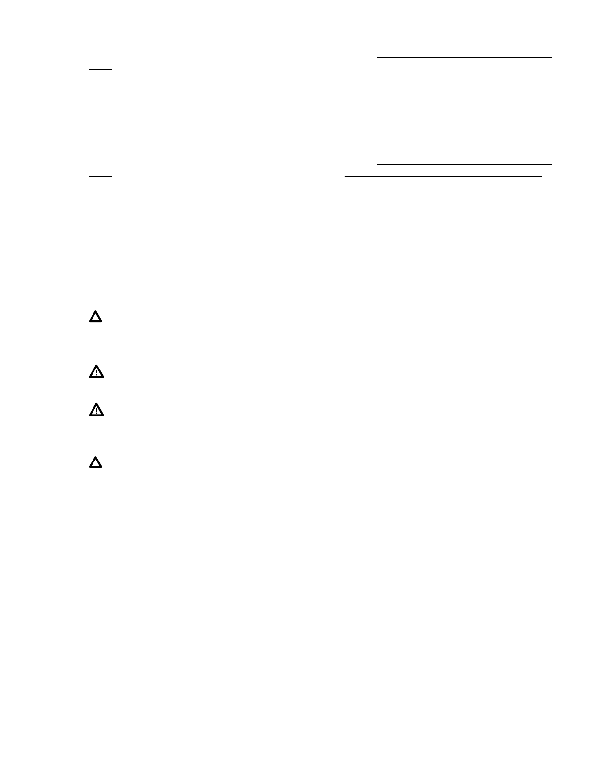
Unlike many rack enclosures, the back of the Apollo 480 Cluster cabinet does not have a master power
switch. The rack individual rear AC breakers must all be switched on prior to booting the system.
Note also that the rack does not have an opening rear door and access is limited.
10 System Operation and Troubleshooting
Page 11
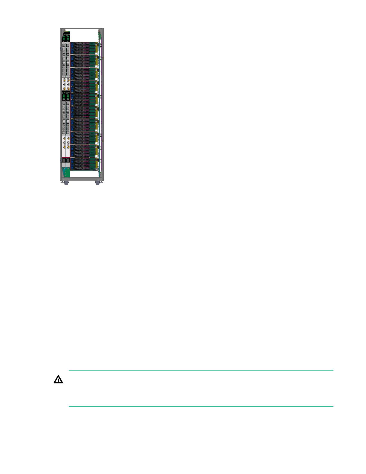
Figure 5: Apollo 480 Cabinet—Back View Example
You can power on each compute node individually using its power button, but this action is normally
accomplished remotely using the interface in the HPE Management Center software.
The compute node power connector is on the rear of each unit. A remote power-on is the normal bring-up
process for nodes.
As listed in the previous chapter, the HPE Apollo 480 Cluster can also be configured as a Hadoop
Reference Implementation system. The cabinet rear sheetmetal is slightly different from the standard
Apollo 480 compute rack.
Upgrading or Replacing Components
The following Apollo 480 Cluster components are field-replaceable:
• Memory DIMMs
• PCIe cards
• Disk drives
• Fans
• Power supplies
They are industry-standard components and must be managed in the conventional manner.
WARNING: If a lithium battery is installed in your system as a soldered part, only service personnel
qualified by HPE can replace this lithium battery. For a battery of another type, replace it only with
the same type or an equivalent type recommended by the battery manufacturer, or an explosion
could occur. Discard used batteries according to the manufacturer instructions.
System Operation and Troubleshooting 11
Page 12
Troubleshooting the System
The following table lists recommended actions for problems that can occur. To solve problems that are not
listed in this table or in another section of this chapter, contact your HPE or other approved service
provider.
Problem Description Recommended Action
The system will not power on.
An individual compute/memory tray will not power
on.
The system will not boot the operating system. Contact your support provider.
An individual populated PCI slot in a tray will not
power on.
The Post Error LED of a populated PCI slot is
illuminated (on).
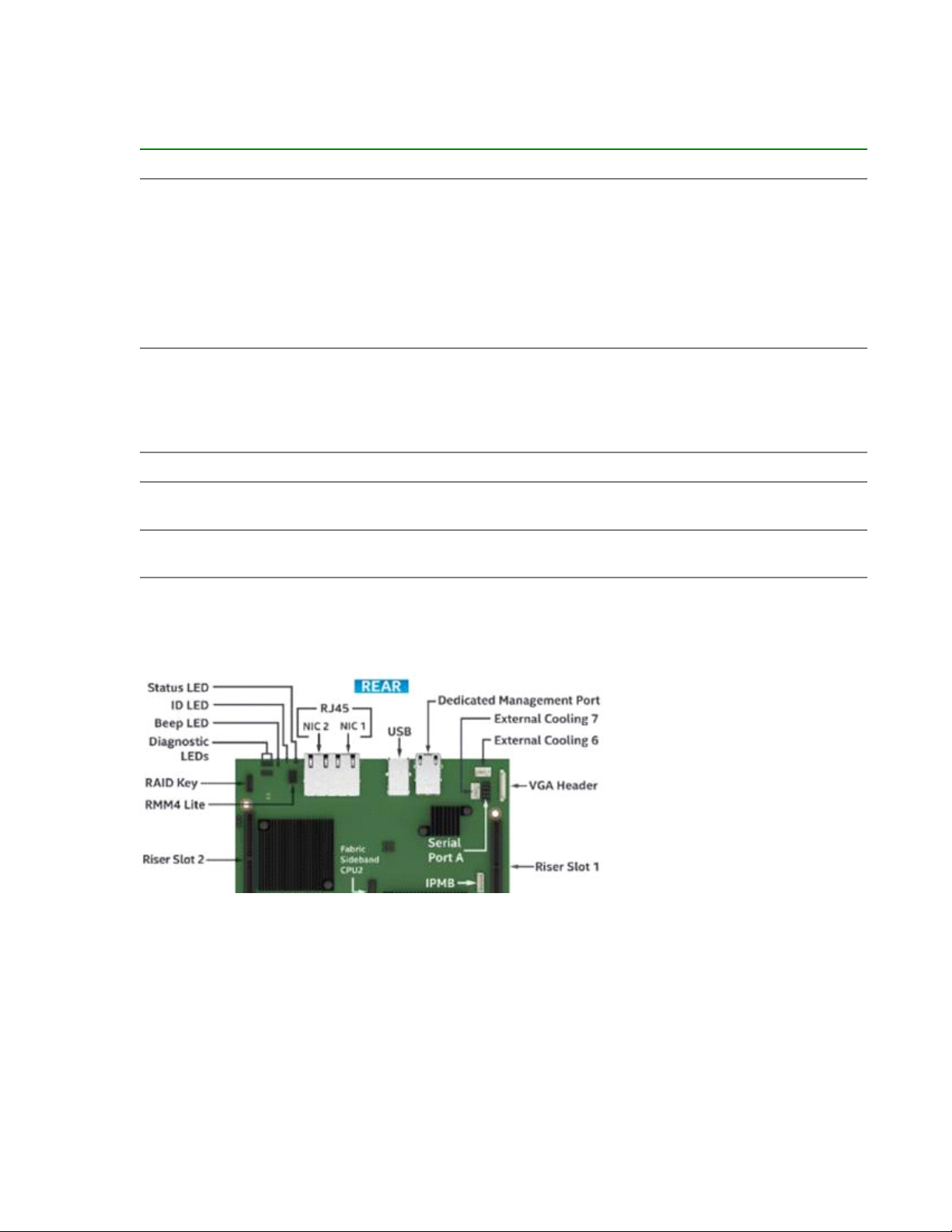
Individual Tray LEDs and Buttons
Each server tray installed in an Apollo 480 Cluster cabinet has LED indicators (upper left of the following
figure) to show the operational status of the tray.
Ensure that the power cord of the cabinet is seated
properly in the power receptacle.
Did you push the power button on the “head node”
compute node as well as the “compute node”
trays?
If the power cord is plugged in and all the power
switches are on, contact your support organization.
View the LED outputs on the rear of the nodes.
Ensure that the unit is plugged in and switched on
If the LEDs are not lit, contact your support
provider.
Reseat the PCI card, reboot the tray, and recheck.
Reseat the PCI card. If the fault LED remains on,
replace the PCI card.
Figure 6: Apollo 480 LED Diagram
The status LEDs are on the right rear section of the tray and are visible when the rear door of the cabinet
is open. The table following describes the tray status LEDs from right to left.
12 System Operation and Troubleshooting
Page 13

LED/Button Display Description
POST Error (Beep) LED Yellow This LED indicates different
errors using flashes.
ID LED Blue This programmable LED is used
for selection and identification of
a particular tray in an Apollo 480
Cluster system rack.
Status LED Yellow/Green When lit, this LED indicates that
functionality is established on the
hard disk drive or solid-state
drive.
POST Error LED Description
1 flash A USB device was inserted or removed while the
system was running.
1 long flash Potential violation of system security detected.
3 flashes Fatal memory error was detected.
3 long flashes followed by 1 flash Fatal CPU error was detected.
The following POST Error LED Codes are used during BIOS Recovery.
2 flashes BIOS recovery was initiated.
4 flashes BIOS recovery failed.
System Operation and Troubleshooting 13
Page 14

Technical Specifications
This appendix contains technical specification information about your system.
System Specifications and Features
The table following lists the physical and electrical specifications of the HPE Apollo 480 Cluster.
System Features Specification
Cabinet height 85.6 in. (217.4 cm)
Cabinet width 24 in. (61 cm)
Cabinet depth 48 in. (121.9)
Weight (full) maximum Approximately 2,579 lbs. Shipping weight will be
Phase required Four three-phase PDUs per rack
greater.
Voltage and CPS range
Power cables Four three-phase pluggable cords per rack
Power supplies Two per compute enclosure (2000W minimum per
Cooling Compute enclosure fans (40mm x4 per enclosure)
Hard drive bays Up to 2 per node, up to 48 in front bay
PCIe slots Optional low-profile (x16) PCI-Express slots on
Environmental Specifications
The table following lists the environmental specifications of the Apollo 480 system.
Feature Specification
Temperature tolerance (operating)
Temperature tolerance (nonoperating) -40°C (-41°F) to +60°C (140°F)
North America - nominal voltage is 208V at 24A per
phase (50/60hz for 3W+PE)
Europe - nominal voltage is 415V at 30A per phase
(50/60hz for 3W+ N+PE)
power supply)
HPC compute nodes
+5°C (45°F) to +35°C (95°F) (up to 1500 m / 5000
ft.)
Relative humidity
Cooling requirement Ambient air cooling
Maximum altitude
Acoustical noise level (sound pressure) Less than 90 dBA maximum
14 Technical Specifications
20% to 80% operating (no condensation)
8% to 80% nonoperating (no condensation)
10,000 ft. (3,049 m) operating
40,000 ft. (12,195 m) nonoperating
Page 15

Regulatory Overview
This chapter provides a summary of the product regulatory compliance.
Category Compliance Information
Electromagnetic Emissions
Safety
RRA Public Notification 2017-19
RRA Announce 2016-71
EN 55032: 2012/AC: 2013
EN 55024: 2010
AS/NZA CISPR 32: 2015
VCCI - CISPR 32: 2016
ICES-003, Issue 6: 2016, Updated April 2017
FCC Part 15 Subpart B
TCVN 7189: 2009
TCVN 7317: 2003
EN 61000-3-11: 2000
EN 61000-3-12: 2011
IEC 61000-3-11: 2000
IEC 61000-3-12: 2011
IEC 60950-1:2005 (Second Edition) + Am 1:2009 +
Am 2:2013
EN 60950-1:2006 / A11:2009 /A1:2010 / A12:2011 /
Am 2:2013
Regulatory Overview 15
Page 16

Websites
General websites
Hewlett Packard Enterprise Information Library
www.hpe.com/info/EIL
Single Point of Connectivity Knowledge (SPOCK) Storage compatibility matrix
www.hpe.com/storage/spock
Storage white papers and analyst reports
www.hpe.com/storage/whitepapers
For additional websites, see Support and other resources.
16 Websites
Page 17

Support and other resources
Accessing Hewlett Packard Enterprise Support
• For live assistance, go to the Contact Hewlett Packard Enterprise Worldwide website:
http://www.hpe.com/assistance
• To access documentation and support services, go to the Hewlett Packard Enterprise Support Center
website:
http://www.hpe.com/support/hpesc
Information to collect
• Technical support registration number (if applicable)
• Product name, model or version, and serial number
• Operating system name and version
• Firmware version
• Error messages
• Product-specific reports and logs
• Add-on products or components
• Third-party products or components
Accessing updates
• Some software products provide a mechanism for accessing software updates through the product
interface. Review your product documentation to identify the recommended software update method.
• To download product updates:
Hewlett Packard Enterprise Support Center
www.hpe.com/support/hpesc
Hewlett Packard Enterprise Support Center: Software downloads
www.hpe.com/support/downloads
Software Depot
www.hpe.com/support/softwaredepot
• To subscribe to eNewsletters and alerts:
www.hpe.com/support/e-updates
• To view and update your entitlements, and to link your contracts and warranties with your profile, go to
the Hewlett Packard Enterprise Support Center More Information on Access to Support Materials
page:
www.hpe.com/support/AccessToSupportMaterials
Support and other resources 17
Page 18

IMPORTANT: Access to some updates might require product entitlement when accessed through
the Hewlett Packard Enterprise Support Center. You must have an HPE Passport set up with
relevant entitlements.
Customer self repair
Hewlett Packard Enterprise customer self repair (CSR) programs allow you to repair your product. If a
CSR part needs to be replaced, it will be shipped directly to you so that you can install it at your
convenience. Some parts do not qualify for CSR. Your Hewlett Packard Enterprise authorized service
provider will determine whether a repair can be accomplished by CSR.
For more information about CSR, contact your local service provider or go to the CSR website:
http://www.hpe.com/support/selfrepair
Remote support
Remote support is available with supported devices as part of your warranty or contractual support
agreement. It provides intelligent event diagnosis, and automatic, secure submission of hardware event
notifications to Hewlett Packard Enterprise, which will initiate a fast and accurate resolution based on your
product's service level. Hewlett Packard Enterprise strongly recommends that you register your device for
remote support.
If your product includes additional remote support details, use search to locate that information.
Remote support and Proactive Care information
HPE Get Connected
www.hpe.com/services/getconnected
HPE Proactive Care services
www.hpe.com/services/proactivecare
HPE Proactive Care service: Supported products list
www.hpe.com/services/proactivecaresupportedproducts
HPE Proactive Care advanced service: Supported products list
www.hpe.com/services/proactivecareadvancedsupportedproducts
Proactive Care customer information
Proactive Care central
www.hpe.com/services/proactivecarecentral
Proactive Care service activation
www.hpe.com/services/proactivecarecentralgetstarted
Warranty information
To view the warranty for your product or to view the Safety and Compliance Information for Server,
Storage, Power, Networking, and Rack Products reference document, go to the Enterprise Safety and
Compliance website:
www.hpe.com/support/Safety-Compliance-EnterpriseProducts
Additional warranty information
HPE ProLiant and x86 Servers and Options
www.hpe.com/support/ProLiantServers-Warranties
HPE Enterprise Servers
www.hpe.com/support/EnterpriseServers-Warranties
18 Support and other resources
Page 19

HPE Storage Products
www.hpe.com/support/Storage-Warranties
HPE Networking Products
www.hpe.com/support/Networking-Warranties
Regulatory information
To view the regulatory information for your product, view the Safety and Compliance Information for
Server, Storage, Power, Networking, and Rack Products, available at the Hewlett Packard Enterprise
Support Center:
www.hpe.com/support/Safety-Compliance-EnterpriseProducts
Additional regulatory information
Hewlett Packard Enterprise is committed to providing our customers with information about the chemical
substances in our products as needed to comply with legal requirements such as REACH (Regulation EC
No 1907/2006 of the European Parliament and the Council). A chemical information report for this product
can be found at:
www.hpe.com/info/reach
For Hewlett Packard Enterprise product environmental and safety information and compliance data,
including RoHS and REACH, see:
www.hpe.com/info/ecodata
For Hewlett Packard Enterprise environmental information, including company programs, product
recycling, and energy efficiency, see:
www.hpe.com/info/environment
Documentation feedback
Hewlett Packard Enterprise is committed to providing documentation that meets your needs. To help us
improve the documentation, send any errors, suggestions, or comments to Documentation Feedback
([email protected]). When submitting your feedback, include the document title, part number,
edition, and publication date located on the front cover of the document. For online help content, include
the product name, product version, help edition, and publication date located on the legal notices page.
Support and other resources 19
 Loading...