

Page 1

Aruba AP 70
Access Point
Installation Guide
Page 2

Copyright
© 2006 Aruba Wireless Networks, Inc. All rights reserved.
Trademarks
Aruba Networks and Aruba The Mobile Edge Company are trademarks of Aruba
Wireless Networks Inc.
Specifications are subject to change without notice.
Sygate On-Demand Agent and Sygate Enforcer are trademarks of Sygate
Technologies.
All other trademarks or registered trademarks are the property of their respective
holders.
Legal Notice
The use of Aruba Wireless Networks, Inc. switching platforms and software, by
all individuals or corporations, to terminate Cisco or Nortel VPN client devices
constitutes complete acceptance of liability by that individual or corporation for
this action and indemnifies, in full, Aruba Wireless Networks, Inc. from any and all
legal actions that might be taken against it with respect to infringement of
copyright on behalf of Cisco Systems or Nortel Networks.
Warranty
This hardware product is protected by the standard Aruba warranty of one year
parts/labor.
For more information, refer to the ARUBACARE SERVICE AND SUPPORT TERMS
AND CONDITIONS.
OTE: Altering this device (such as repainting it) voids the warranty.
N
ii Aruba AP 70 0510159-02
Installation Guide September 2006
Page 3

Contents
Preface . . . . . . . . . . . . . . . . . . . . . . . . . . . . . . . . . . . . . . . . . . . . . . . . . . . v
Overview of this Manual. . . . . . . . . . . . . . . . . . . . . . . . . . . . . . . . . . . . . v
Related Documents
Text Conventions
Contacting Aruba Networks
Chapter 1 Introduction. . . . . . . . . . . . . . . . . . . . . . . . . . . . . . . . . . . . . . . . . . . . . . 1
Front View . . . . . . . . . . . . . . . . . . . . . . . . . . . . . . . . . . . . . . . . . . . . . . . . . . 1
Back View
The Aruba AP Deployment Process
Chapter 2 AP Installation. . . . . . . . . . . . . . . . . . . . . . . . . . . . . . . . . . . . . . . . . . . 7
Enabling APs to Connect to the Mobility Controller. . . . . . . . . . . . 7
Enable APs to Obtain IP Addresses
Locate the Mobility Controller
Mounting the Aruba AP 70
Free-Standing Placement
Using the Built-In Mounting Slots
Using the Optional Mounting Kits
Connecting Required Cables
Selecting an FE Cable
Connecting Cables and Power
. . . . . . . . . . . . . . . . . . . . . . . . . . . . . . . . . . . . . . . . . . . . . . . . . . 5
. . . . . . . . . . . . . . . . . . . . . . . . . . . . . . . . . . . . . . . . . . v
. . . . . . . . . . . . . . . . . . . . . . . . . . . . . . . . . . . . . . . . . . . vi
. . . . . . . . . . . . . . . . . . . . . . . . . . . . . . . . vii
. . . . . . . . . . . . . . . . . . . . . . . . . . 6
. . . . . . . . . . . . . . . . . . . . . . . . 7
. . . . . . . . . . . . . . . . . . . . . . . . . . . . . 8
. . . . . . . . . . . . . . . . . . . . . . . . . . . . . . . . . . 9
. . . . . . . . . . . . . . . . . . . . . . . . . . . . . . . . . 10
. . . . . . . . . . . . . . . . . . . . . . . . . 11
. . . . . . . . . . . . . . . . . . . . . . . . . 12
. . . . . . . . . . . . . . . . . . . . . . . . . . . . . . . . 13
. . . . . . . . . . . . . . . . . . . . . . . . . . . . . . . . . . . . 13
. . . . . . . . . . . . . . . . . . . . . . . . . . . . 14
Appendix A Port Specifications. . . . . . . . . . . . . . . . . . . . . . . . . . . . . . . . . . . . . 15
FE Ports . . . . . . . . . . . . . . . . . . . . . . . . . . . . . . . . . . . . . . . . . . . . . . . . . . . 15
Serial Breakout Adapter
DB-9 Specification
“To AP” Specifications
“To Network” Specifications
USB Port
Appendix B Product Specifications . . . . . . . . . . . . . . . . . . . . . . . . . . . . . . . . 19
. . . . . . . . . . . . . . . . . . . . . . . . . . . . . . . . . . . . . . . . . . . . . . . . . . . 18
. . . . . . . . . . . . . . . . . . . . . . . . . . . . . . . . . . . . . 16
. . . . . . . . . . . . . . . . . . . . . . . . . . . . . . . . . . . . . . . 17
. . . . . . . . . . . . . . . . . . . . . . . . . . . . . . . . . . . 17
. . . . . . . . . . . . . . . . . . . . . . . . . . . . . . 17
Aruba AP 70 iii
Installation Guide
Page 4

Contents
Compliance . . . . . . . . . . . . . . . . . . . . . . . . . . . . . . . . . . . . . . . . . . . . . . . . 19
United States
Canada
Japan
Europe
Product Label
Certifications
Product Features
Ethernet Compatibility
Radio Characteristics
Power Over Ethernet
Physical Description
Package Contents
Optional Items
AP 70 Specifications
Proper Disposal of Aruba Equipment
. . . . . . . . . . . . . . . . . . . . . . . . . . . . . . . . . . . . . . . . . . . . . . . . . . 20
. . . . . . . . . . . . . . . . . . . . . . . . . . . . . . . . . . . . . . . . . . . . . . . . . . . 21
. . . . . . . . . . . . . . . . . . . . . . . . . . . . . . . . . . . . . . . . . . . . . . . . . . 21
. . . . . . . . . . . . . . . . . . . . . . . . . . . . . . . . . . . . . . . . . . . . 19
. . . . . . . . . . . . . . . . . . . . . . . . . . . . . . . . . . . . . . . . . . . . 22
. . . . . . . . . . . . . . . . . . . . . . . . . . . . . . . . . . . . . . . . . . . . . . . 22
. . . . . . . . . . . . . . . . . . . . . . . . . . . . . . . . . . . . . . . . . . . 23
. . . . . . . . . . . . . . . . . . . . . . . . . . . . . . . . . . . . 23
. . . . . . . . . . . . . . . . . . . . . . . . . . . . . . . . . . . . . 23
. . . . . . . . . . . . . . . . . . . . . . . . . . . . . . . . . . . . . 24
. . . . . . . . . . . . . . . . . . . . . . . . . . . . . . . . . . . . . . . . 24
. . . . . . . . . . . . . . . . . . . . . . . . . . . . . . . . . . . . . . . 24
. . . . . . . . . . . . . . . . . . . . . . . . . . . . . . . . . . . . . . . . . . . 24
. . . . . . . . . . . . . . . . . . . . . . . . . . . . . . . . . . . . . . . 25
. . . . . . . . . . . . . . . . . . . . . . . . 29
iv Aruba AP 70 0510159-02
Installation Guide September 2006
Page 5

Preface
This preface includes the following information:
An overview of the sections in this manual
A list of related documentation for further reading
A key to the various text conventions used throughou t this manual
How to contact Aruba Wireless Networks
Overview of this Manual
This manual is for trained technicians responsible for installing the Aruba AP 70
access point.
Related Documents
The following items are part of the complete documentation for the Aruba
system:
Aruba AP 70 Wireless Access Point Installation Guide (this document)
Aruba Mobility Controller Installation Guide
ArubaOS User Guide
For the current versions of these manuals, or to obtain the latest product release
notes, visit the support section of our Web site (see page vii).
Aruba AP 70 v
Installation Guide
Page 6

Preface
Text Conventions
The following conventions are used throughout this manual to emphasize
important concepts:
TABLE 1 Text Conventions
Type Style Description
Italics This style is used to emphasize important terms and to mark
the titles of books.
System items This fixed-width font depicts the following:
Sample screen output
System prompts
Filenames, software devices, and certain commands
when mentioned in the text
Commands In the command examples, this bold font depicts text that
the user must type exactly as shown.
<Arguments> In the command examples, italiciz ed text within angle
brackets represents items that the user should replace with
information appropriate to their specific situation. For
example:
# send <text message>
In this example, the user would type “send” at the system
prompt exactly as shown, followed by the text of the
message they wish to send. Do not type the angle brackets.
[ Optional ] In the command examples, items enclosed in brackets are
optional. Do not type the brackets.
{ Item A | Item B } In the command examples, items within curled braces and
separated by a vertical bar represent the available choices.
Enter only one choice. Do not type the braces or bars.
vi Aruba AP 70 0510159-02
Installation Guide September 2006
Page 7
Preface
Contacting Aruba Networks
Web Site
Main Site http://www.arubanetworks.com
Support Site http://www.arubanetworks.com/support
Software Licensing Site https://licensing.arubanetworks.com
Wireless Security Incident
Response Team (WSIRT)
Please email details of any security
problem found in an Aruba product.
Telephone Numbers
Aruba Corporate +1 (408) 227-4500
FAX +1 (408) 227-4550
Support
z United States 800-WI-FI-LAN (800-943-4526)
z France +33 (0) 1 70 72 55 59
z United Kingdom +44 (0) 20 7127 5989
z Germany +49 (0) 69 38 09 77 22 8
z All other countries +1 (408) 754-1200
http://www.arubanetworks.com/support
/wsirt
Aruba AP 70 vii
Installation Guide
Page 8

Preface
viii Aruba AP 70 0510159-02
Installation Guide September 2006
Page 9

Introduction
The Aruba AP 70 works in conjunction with the Aruba Mobility Controller and can
act as a wireless access point or air monitor.
As a wireless Access Point (AP), the Aruba AP 70 pr ovides transparent, secure,
high-speed data communications between wireless network devices (fixed,
portable, or mobile computers with IEEE 802.11a or IEEE 802.11b/g wireless
adapters) and the wired LAN.
As a wireless Air Monitor (AM), a feature unique to Aruba products, the Aruba AP
70 enhances wireless networks by collecting statistics, monitoring traffic,
detecting intrusions, enforcing security policies, balancing wireless traffic load,
self-healing coverage gaps, and more.
OTE: Service to all Aruba Networks equipment must be performed by trained
N
service personnel only.
Front View
1
This section describes the components on the front of the AP 70 (Figure 1-1).
Aruba AP 70 1
Installation Guide
Page 10

Introduction
Chapter 1
5
4
3
6
2
2
7
9
8
1
FIGURE 1-1 Aruba AP 70 Front View
2 Aruba AP 70 0510159-02
Installation Guide September 2006
Page 11
Fold-Out Internal Antenna
1
The fold-out antenna allows the Aruba 70 to be placed on a flat table or shelf,
mounted on a wall, or suspended from a ceiling (an optional mounting kit is
available). If you are configuring external antennas, the internal antenna can be
left closed.
The serial number and the model number are on the bottom of the fold-out
antenna panel.
OTE: For best performance, swivel the antenna array so that it is oriented
N
vertically. For more information, see Chapter 2, “AP Installation,”.
2
Indicator LEDs
During operation, the Aruba AP 70 LEDs provide the following information:
TABLE 1-1 Aruba AP 70 LEDs
LED State Description
PWR Off The device is off - no power.
Green-Solid The device is powered and operating.
Green-Flashing The device is powered but is not ready for oper ation
(typically, the AP is booting).
ENET0/1 Off No link on the FE port. No connection to the
network.
Green-Solid Ethernet link detected on the FE port.
Green-Flashing Transmitting or receiving data across the FE port.
Flashing rate is proportional to network activity.
A Off The wireless interface is disabled or down.
Green-Solid The wireless interface is enabled and functioning as
an Access Point.
Green-Flashing The wireless interface is ena bled and functioning as
an Air Monitor.
B/G Off The wireless interface is disabled or down.
Green-Solid The wireless interface is enabled and functioning as
an Access Point.
Green-Flashing The wireless interface is ena bled and functioning as
an Air Monitor.
a
Introduction
Chapter 1
b
a.The ENET1 LED on Aruba AP 70 rev D and earlier models configured for 10Base-T
traffic does not illuminate, but traffic is processed normally. The ENET1 LED on Aruba
AP 70 rev E and later models (circa March, 2005 and later) illuminates when configured for 10Base-T traffic.
b.The ENET1 LED does not flash when traffic is being processed when configured for
10Base-T half duplex traffic. However, traffic is being processed properly.
Aruba AP 70 3
Installation Guide
Page 12

Introduction
Chapter 1
NOTE: LEDs on some Mobility Controller models provide additional status and
security information about directly-connected APs. See the Installation
Guide for the Mobility Controller for more i nformation.
3
Air Vents
These vents promote proper air circulation for cooling the device. Do not allow
these vents to be obstructed by mounting equipment, network cables, or any
other material.
4
FE Ports
The ENET0 and ENET1 ports attach the Aruba AP 70 to a 10Base-T/100Base-TX
(twisted-pair) Ethernet LAN segment. Both ports support Power over Ethernet
(POE). ENET0 also supports Serial Over Ethernet (SOE).
5
USB Ports
This port is used to connect the AP to a host computer to support application
specific functionality and for future applications in the RF environment such as
RFID tracking or spectrum analysis.
6
DC Power Socket
This socket is used to connect the optional AC power ada p ter (not included). If
POE is being used to supply power to the Aruba AP 70, the power adapter is not
necessary.
7
B/G Antenna Jack
For external antenna connection.
8
A Antenna Jack
For external antenna connection.
9
Kensington Security Slot
This slot is compatible with a Kensington MicroSaver Security Cable (not
included), which can be used to prevent the unauthorized removal of the Aruba
AP 70 from its installed location. To secure the Aruba AP 70, wrap a security
cable around an immovable object, insert the cable’s lock into the Kensington
Security Slot, and turn the key.
To use the Kensington Security Slot while th e Aruba AP 70 is mounted by the
mounting slots, the fold-out internal antenna must be in an open position.
See Appendix 3, “Port Specifications” for port and cable specifications.
4 Aruba AP 70 0510159-02
Installation Guide September 2006
Page 13
Back View
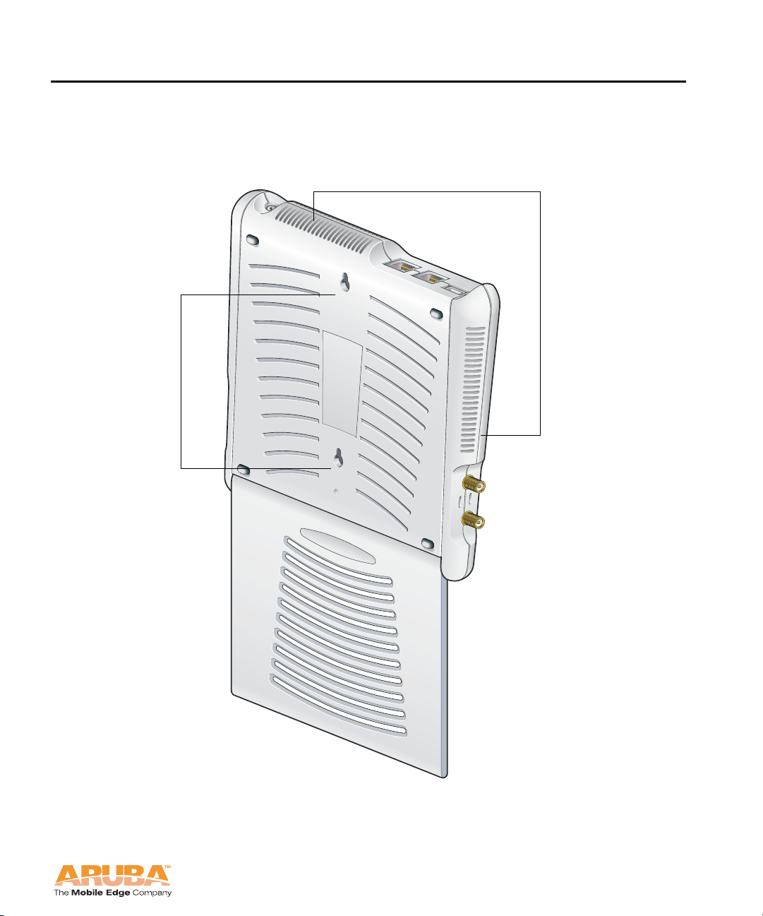
This section describes the components on the back of the AP 70 (Figure 1-2).
2
1
2
Introduction
Chapter 1
FIGURE 1-2 Aruba AP 70 Back View
Aruba AP 70 5
Installation Guide
Page 14

Introduction
Chapter 1
Mounting Slots
1
The keyhole-shaped slots on the back of the chassis are used for mounting the
Aruba AP 70.
2
Air Vents
These vents promote proper air circulation for cooling the device. Do not allow
these vents to be obstructed by mounting equipment, network cables, or any
other material.
The Aruba AP Deployment Process
Deploying an Aruba AP typically consists of four stages:
1. Run Aruba’s automated RF Plan site-survey software (available separ ately) to
determine how many Aruba APs are needed and where they will be installed.
2. Ensure that the APs can locate the Mobility Controller when they a re installed
and connected to the network.
This is covered in Chapter 2, “AP Installation”.
3. Install the APs by connecting the AP to an Ethernet port and, optionally, to a
power source.
This is covered in Chapter 2, “AP Installation”.
4. On the Mobility Controller, provision the APs.
For AP configuration information, refer to the ArubaOS User Guide.
6 Aruba AP 70 0510159-02
Installation Guide September 2006
Page 15
AP Installation
This chapter explains how to enable APs to connect to an Aruba Mobility
Controller, and how to install and connect the Aruba AP 70.
Enabling APs to Connect to the Mobility Controller
Before you install APs in a network environment, you mus t ensure that the APs
will be able to locate and connect to the Mobility Controller when powered on.
Specifically, you need to ensure the following:
When connected to the network, each AP is assigned a valid IP address
APs are able to locate the Mobility Controller
NOTE: Aruba APs use Trivial File Transfer Protocol (TFTP) the first time they
boot to obtain their software image and configuration from the Mobility
Controller. After the initial boot, the APs use FTP to obtain software
images and configurations from the Mobility Controller.
2
Enable APs to Obtain IP Addresses
Each Aruba AP requires a unique IP address on a subnetwork that has
connectivity to a Mobility Controller. Aruba recommends using the Dynamic Host
Configuration Protocol (DHCP) to provide IP addresses for APs; the DHCP server
can be an existing network server or an Aruba Mobility Controller configured as a
DHCP server.
You can use an existing DHCP server in the same subnetwork as the AP to
provide the AP with its IP information. You can also configure a device in the
same subnetwork to act as a relay agent for a DHCP server on a different
subnetwork. Refer to the vendor documentation for the DHCP Server or relay
agent for information.
If an AP is on the same subnetwork as the master Mobility Controller, y ou can
configure the Mobility Controller as a DHCP server to assign an IP a ddress to the
AP. The Mobility Controller must be the only DHCP server for this subnetwork.
See the ArubaOS User Guide for information on how to enable DHCP server
capability on a Mobility Controller:
Aruba AP 70 7
Installation Guide
Page 16

AP Installation
Chapter 2
Locate the Mobility Controller
An Aruba AP can discover the IP address of the Mobility Controller in one of the
following ways:
From a DNS server
From a DHCP server
Using the Aruba Discovery Protocol (ADP)
From a DNS Server
Aruba APs are factory-configured to use the host name aruba-master for the
Mobility Controller. For the DNS serve r to resolve this host name to the IP address
of the Mobility Controller, you must configure an entry on the DNS server for the
name aruba-master.
For information on how to configure a host name entry on the DNS server, refer
to the vendor documentation for your server.
OTE: Aruba recommends using a DNS server to provide APs with the IP
N
address of the master Mobility Controller because it involves minimal
changes to the network and provides the greatest flexibility in the
placement of APs.
From a DHCP Server
You can configure a DHCP server to provide the Mobility Controller’s IP address.
You need to configure the DHCP server to send the Mobility Controller’s IP
address using the DHCP vendor-specific attribute option 43. Aruba APs identify
themselves with a vendor class identifier set to ArubaAP in their DHCP request.
When the DHCP server responds to the request, it will send the controller’s IP
address as the value of option 43.
For more information on how to configure vendor-specific information on a DHCP
server, see the ArubaOS User Guide or refer to the vendor documentation fo r your
server.
Using the Aruba Discovery Protocol (ADP)
ADP is enabled by default on all Aruba APs and Mobility Controllers. To use ADP,
all Aruba APs and Mobility Controllers must be connected to the same Layer-2
network. If the devices are on different networks, a Layer-3 compatible discovery
mechanism, such as DNS, DHCP, or IGMP forwarding, must be used instead.
With ADP, APs send out periodic multicast and broadcast queries to locate the
Mobility Controller. You may need to perform additional network configuration,
depending on whether the APs are in the same broadcast domain as th e Mobility
Controller:
If the APs are in the same broadcast domain as the Mobility Controller, the
controller automatically responds to the APs’ queries with its IP addres s.
8 Aruba AP 70 0510159-02
Installation Guide September 2006
Page 17

AP Installation
If the APs are not in the same broadcast domain as the Mobility Controller,
you need to enable multicast on the network (ADP multicast queries are sent
to the IP multicast group address 224.0.82.11) for the controller to respond
to the APs’ queries. You also need to make sure that all routers are
configured to listen for Internet Group Management Protocol (IGMP) join
requests from the Mobility Controller and can route these multicast pack ets.
See the ArubaOS User Guide for more information about enablin g ADP on the
Mobility Controller.
Mounting the Aruba AP 70
Mount the Aruba AP 70 at its intended service location.
The Aruba AP 70 Access Points are intended only for installation in Envir onment
A as defined in IEEE 802.3.af. All interconnected equipment must be contained
within the same building, including the interconnected equipment's associated
LAN connections.
Select a location as close as possible to the center of the intended cover age area.
If necessary, use the Aruba RF Plan site survey tool to determine the optimum
locations for your access points and air monitors.
The service location should be free from obstructions or obvious sources of
interference. Normally, the higher you place an acc ess point or air monitor, the
better its performance.
Chapter 2
Aruba AP 70 9
Installation Guide
Page 18
AP Installation
Chapter 2
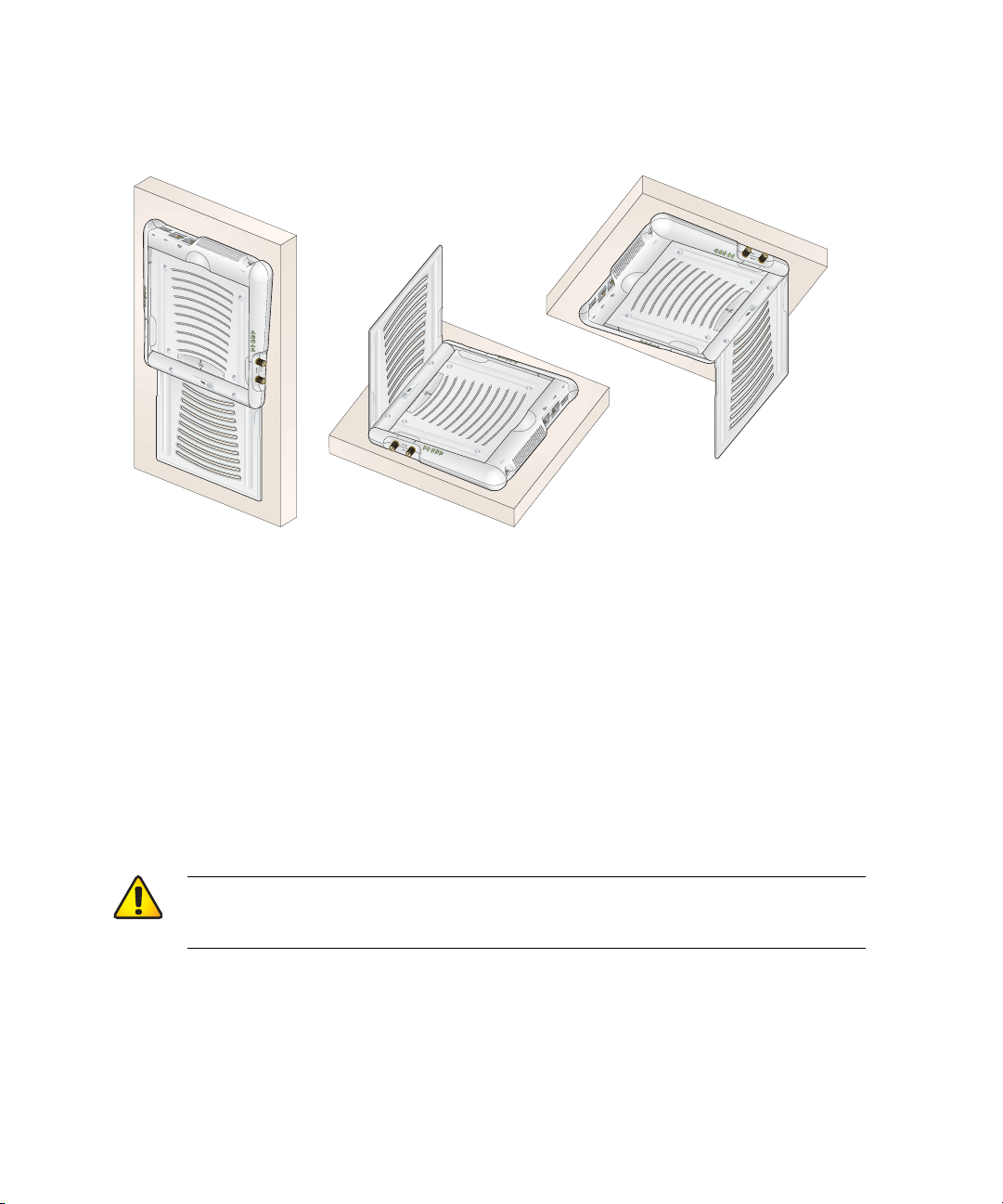
The Aruba AP 70 can be mounted on a wall or suspended from above (not
shown) using one of the optional mounting kits (dimensions v ary) in the following
ways:
FIGURE 2-1 Aruba AP 70 Mounting Options
NOTE: For dimensions, see Appendix 4, “Product Spec ifications”. Allow 5 cm
(2") additional space on the right-hand side for cables. Measurements for
the Aruba AP 70 depend on attached antennas, which vary.
Free-Standing Placement
To place the Aruba AP 70 indoors on a flat table or shelf:
1. Flip open the Aruba AP 70 internal antenna.
2. Place the device on a sturdy table or shelf.
CAUTION: Do not place the Aruba AP 70 in any place where it could
fall on people or equipment. For more secure installation,
use one of the optional mounting kits.
3. Orient the antennas.
For best performance, swivel the antenna arr ay s o that it is oriented vertically.
Once mounting is complete, connect the required cables (see instructions on
page 13).
10 Aruba AP 70 0510159-02
Installation Guide September 2006
Page 19
AP Installation
Chapter 2
Using the Built-In Mounting Slots
The keyhole-shaped slots on the back of the Aruba AP 70 can be used to attach
the device upright to an indoor wall or shelf.
CAUTION: Do not use the mounting slots to hang the Aruba AP 70
from the ceiling, sideways, or in any place where it could
fall on people or equipment. For more secure installation,
use one of the optional mounting kits.
To hang the Aruba AP 70 upright using the mounting slots, perform the following
steps.
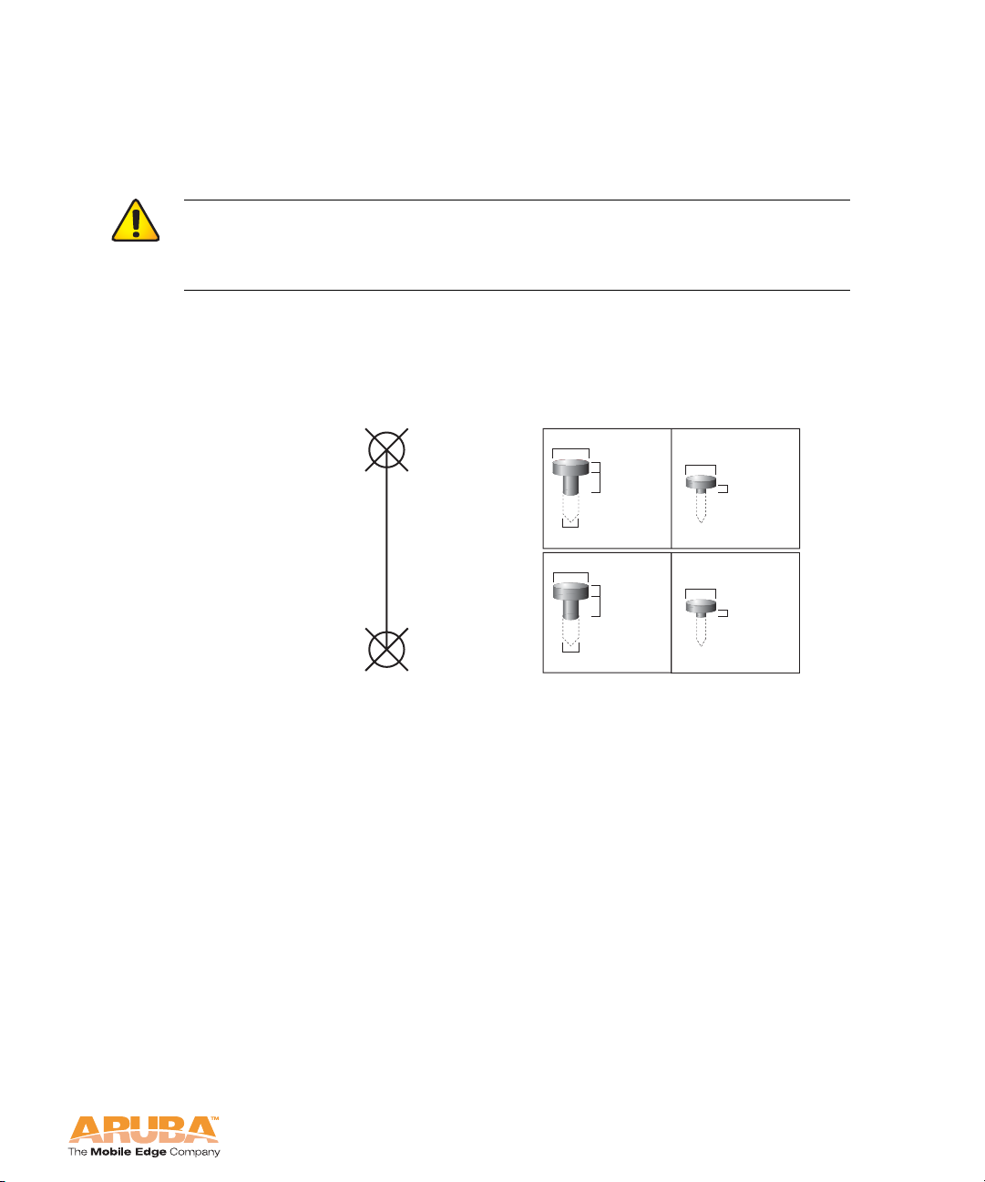
1. Install two screws in the wall or shelf as shown in Figure 2-2:
Screw/Nail Positions
(fastened to wall or shelf)
10 cm
(3 15/16")
Screw/Nail Dimensions
Maximum Minimum
5.6 mm
2.4 mm
7/32"
3/32"
1.6 mm
4.0 mm
clearance
from surface
1/16"
5/32"
clearance
from surface
4.8 mm
3/16"
2.4 mm
clearnace
from surface
3/32"
clearance
from surface
FIGURE 2-2 Mounting Screw Specifications
If attaching the device to drywall, we recommend using appropriate wall
anchors (not included) as shown in Figure 2-3 on page 12.
Aruba AP 70 11
Installation Guide
Page 20
AP Installation
Chapter 2
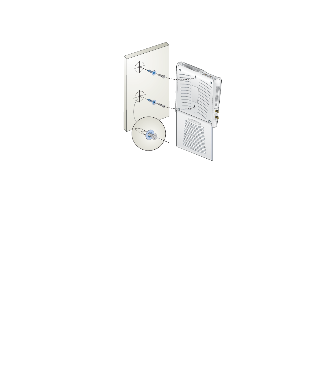
2. Align the Aruba AP 70 mounting slots to capture the surface screws.
FIGURE 2-3 Hanging the Aruba AP 70 on Screws
3. Secure the Aruba AP 70, if desired.
To prevent the unauthorized removal of the Aruba AP 70 from its installed
location, use a Kensington MicroSaver Security Cable (not included). Wrap
the security cable around an immova ble object, insert the ca ble’ s lo ck into the
Kensington Security Slot on the back of the Aruba AP 70, and turn the key.
4. Orient the antennas.
For best performance, swivel the antenna arr a y so that it is oriented vertically
(see Figure 2-1 on page 10). Once mounting is complete, connect the
required cables (see instructions on page 13).
Using the Optional Mounting Kits
Use the optional mounting kit to attach the Aruba AP 70 to a wall, shelf, or
ceiling. For installation, see the Aruba AP 70 Mounting Kit Installation Notes
provided with each kit.
12 Aruba AP 70 0510159-02
Installation Guide September 2006
Page 21

AP Installation
Connecting Required Cables
The Aruba AP 70 Access Points are intended only for installation in Envir onment
A as defined in IEEE 802.3.af. All interconnected equipment must be contained
within the same building, including the interconnected equipment's associated
LAN connections.
Selecting an FE Cable
The 10/100 Mbps Ethernet (FE) port is used to connect the AP to a
10Base-T/100Base-TX (twisted-pair) Ethernet LAN segment. The appropriate FE
cable depends on the features required of the FE port:
SPOE
When connecting the AP to a device that supports Serial and Power Over
Ethernet (SPOE), use an 8-conductor, Category 5 UTP, straig ht-through FE
cable.
The Aruba 5000 (with Line Card LC-5000-24FE-2GE-SPOE), the Aruba 2400,
and the Aruba 800 support SPOE.
POE
Chapter 2
If the connecting device supports only P ower Over Ethernet (POE), use a 4- or
8-conductor, Category 5 UTP, straight-through FE cable.
Network Only
If the connecting device does not support POE, use a 4- or 8-conductor,
Category 5 UTP, FE cable. The ENET0 port detects MDI/MDX and
automatically adjusts for straight-through or crossover cables.
The maximum length for FE cables is 100 meters (325 feet).
When the Aruba AP 70 is installed in an air-handling space, such as above
suspended ceilings, as described in National Electrical Code (2002) Article
300.22(C), and Canadian Electrical Code, Sections 2-128, 12-010(3) and 12-100,
Part 1, CSA C22.1, POE is required. Also, any FE cable installed in such spaces
should be suitable under NEC Article 800.50 and marked accordingly for use in
plenums and air-handling spaces with regard to smoke propagation, such as
CL2-P, CL3-P, MPP, or CMP.
Install cables in accordance with all applicable local and national regulations and
practices.
See Appendix 3, “Port Specifications” for port and cable details.
Aruba AP 70 13
Installation Guide
Page 22

AP Installation
Chapter 2
Connecting Cables and Power
CAUTION: To prevent personal injury or damage to equipment, be
sure to comply with electrical gr ou nding standards during
all phases of installation and operation of the AP. Do not
allow the Aruba AP 70 or its attachments to be connected
to or make contact with metal or power outlets on a
different electrical ground than the device to which it is
connected. Also, never connect the AP or Mobility
Controller to external storm grounding sources.
To connect the FE port on the AP 70:
1. Connect one end of the FE cable directly to the Aruba AP 70 FE port.
2. Connect the other end of the FE cable to one of the following:
z To a network port on the Mobility Controller, or
z To a network hub, router, or Mobility Controller that has a routable path
to the Mobility Controller.
OTE: If the connecting device supplies POE, a straight-through cable must
N
connect the Aruba AP 70 directly to the powering device without any
intervening hubs, routers, or other networking equipment.
3. Connect power, if necessary.
The Aruba AP 70 can receive electrical power using the following options:
z POE
If connecting the Aruba AP 70 to a device that supplies IEEE 802.3af
compliant POE no additional power connection is necessary.
z Power Outlet
NOTE: When the Aruba AP 70 is installed in an air-handling space, as
described in NEC (2002) Article 300.22(C), POE must be used
instead of a power outlet.
If local regulations and practices permit, connect the optional AC power
adapter (not included) to the DC power socket on the Aruba AP 70 and
plug it into an appropriate power outlet.
CAUTION: To prevent personal injury or damage to equipment,
use only the AC power adapter certified for this device
in the country where it is used.
14 Aruba AP 70 0510159-02
Installation Guide September 2006
Page 23
Port Specifications
FE Ports
The ENET0 and ENET1 10/100 Mbps Ethernet ports attach the Aruba 70 to a
10Base-T/100Base-TX (twisted pair) LAN segment. Both ports support Power
over Ethernet (P oE). ENET0 also supports Serial over Ethernet (SoE) and
auto-sensing MDI/MDX.
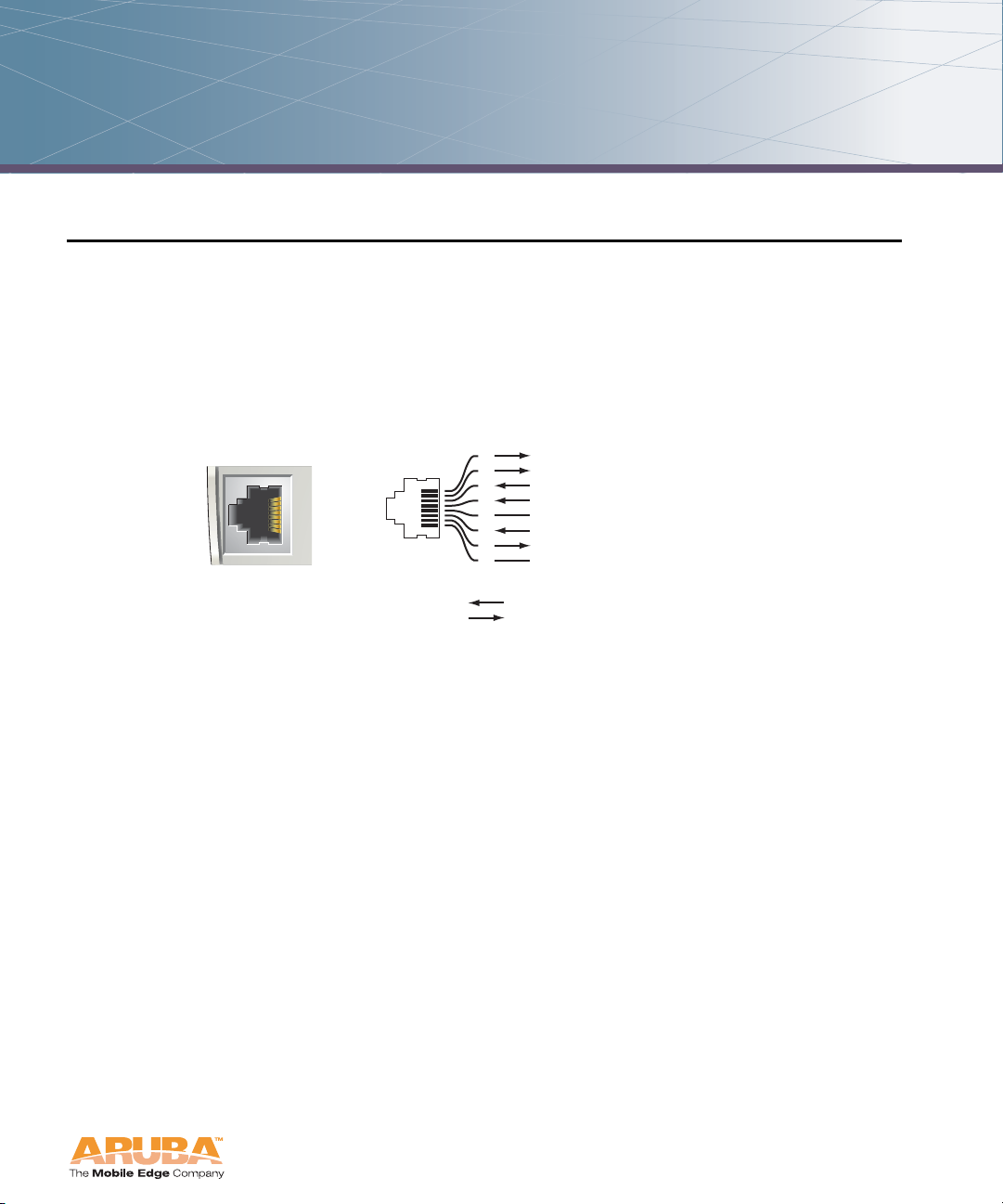
The port pin-outs are shown in Figure A-1:
A
10/100 Mbps Ethernet
AP70
RJ-45 Female
Pin-Out
Direction
Input
Output
1
2
3
4
5
6
7
8
ETH Tx+ (POE negative*)
ETH Tx– (POE negative*)
ETH Rx+ (POE positive*)
Serial RxD**
Serial RGND** (POE positive*)
ETH Rx– (POE positive*)
Serial TxD**
Serial TGND** (POE negative*)
*POE optional
**Serial optional
FIGURE A-1 Aruba AP 70 FE Port
The appropriate cable depends on the level of connectivity required of the FE port:
If the connecting device supports Serial and P ower Over Ethernet (SPOE), use
an 8-conductor, Category 5 UTP, straig ht-through FE ca ble with a male RJ-45
connector.
The Aruba 5000 (with Line Card LC-5000-24FE-2GE-SPOE), the Aruba 2400, and
the Aruba 800 support SPOE.
If the connecting device supports only Power Over Ethernet (POE, including
IEEE 802.3af POE as well as “inline” or “midspan” POE devices), use an 8 - or
4-conductor, Category 5 UTP, straight-through FE cable with male RJ-45
connectors.
If the connecting device does not support Serial or POE, use a 4- or
8-conductor, Category 5 UTP, FE cable with male RJ-45 connectors. The
ENET0 port detects MDI/MDX and automatically adjusts for straight-through
or crossover cables.
The maximum length for FE cables is 100 meters (325 feet).
Aruba AP 70 15
Installation Guide
Page 24
Port Specifications
Appendix A
When the Aruba AP 70 is installed in an air-handling space, as described in NEC
(2002) Article 300.22 (C), POE is required. Also, any FE cable installed in such
spaces should be suitable under NEC Article 800.50 and marked accordingly for
use in plenums and air-handling spaces with regard to smoke propagation, such
as CL2-P, CL3-P, MPP or CMP.
Install cables in accordance with all applicable local regulations and practices.
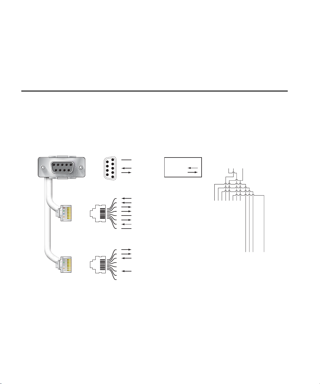
Serial Breakout Adapter
The optional serial breakout adapter is used to separate the serial
communications lines from the Aruba AP 70 FE+SPOE port. This allows the
administrator to connect a local serial console directly to the AP and access the
apboot prompt for manual provisioning.
The serial breakout adapter pin-outs are shown in Figure A-2:
DB-9 Female Pin-Out
SG
9
8
7
6
5
4
TxD
3
RxD
2
1
Direction
Input
Output
Internal Adapter Wiring
To Console
123456789
RJ-45 Male "To AP" Pin-Out
1
ETH Rx+ (POE negative)
2
ETH Rx– (POE negative)
ETH Tx+ (POE positive)
3
Serial TxD
4
Serial TGND
5
6
ETH Tx– (POE positive)
Serial RxD
7
Serial RGND
8
RJ-45 Male "To Network" Pin-Out
1
ETH Tx+ (POE negative)
2
ETH Tx– (POE negative)
3
ETH Rx+ (POE positive)
4
5
ETH Rx– (POE positive)
6
7
8
FIGURE A-2 Aruba Serial Breakout Adapter
12345678
"To AP"
12345678
"To Network"
16 Aruba AP 70 0510159-02
Installation Guide September 2006
Page 25

Port Specifications
Appendix A
DB-9 Specification
The DB-9 connector attaches to the serial port of a console terminal.
Communication settings for the port are specified in Table A-1:
TABLE A-1 Console Terminal Settings
Baud Rate Data Bits Parity Stop Bits Flow Control
9600 8 None 1 None
“To AP” Specifications
The RJ-45 connector labeled “To AP” attaches to the Aruba AP 70 FE port either
directly (if the AP is physically available) or indirectly (if the AP is already
deployed).
When connecting indirectly, use a straight-through FE coupler to attach the “To
AP” connector to the FE cable leading directly to the AP’s FE port with no
intervening hubs, routers, or other network equipment. The cable mu st be
8-conductor, Category 5 UTP, straight-through FE cable with a maximum length
of 100 meters (325 feet).
The Aruba AP 70 and serial breakout adapter are plenum rated. When is installed
in an air-handling space, as described in NEC (2002) Article 300.22(C), any
connecting FE cable should be suitable under NEC Article 800.50 and marked
accordingly for use in plenums and air-handling spaces with regard to smoke
propagation, such as CL2-P, CL3-P, MPP or CMP.
Install cables in accordance with all applicable local regulations and practices.
“To Network” Specifications
The RJ-45 connector labeled “To Network” attaches to an FE LAN segment. This
connection is optional unless IEEE 802.11af Power Over Ethernet (POE) is used to
power the AP during manual provisioning.
A straight-through FE coupler may be used to attach the “To Network” connector
to a LAN FE cable. The appropriate cable depends on the level of connectivity
required of the FE port.
If the connecting device supports IEEE 802.3af Power Over Ethernet (POE),
use a 4- or 8-conductor, Category 5 UTP, straight-through FE cable with male
RJ-45 connectors.
The Aruba 5000 (with Line Card LC-5000-24FE-2GE-SPOE), the Aruba 2400, and
the Aruba 800 support SPOE.
Otherwise, use a 4- or 8-conductor, Category 5 UTP, FE cable with male
RJ-45 connectors. The ENET0 port detects MDI/MDX and automatically
adjusts for straight-through or crossover cables.
Aruba AP 70 17
Installation Guide
Page 26

Port Specifications
Appendix A
NOTE: Only IEEE 802.3af Power Over Eth ernet is supported for manual
provisioning. “Inline” or “midspan” POE devices will not work with the
Aruba serial breakout adapter.
The maximum length for FE cables is 100 meters (325 feet).
The Aruba AP 70 and serial breakout adapter are plenum rated. When is installed
in an air-handling space, as described in NEC (2002) Article 300.22(C), the
connecting FE cable should be suitable under NEC Article 800.50 and marked
accordingly for use in plenums and air-handling spaces with regard to smoke
propagation, such as CL2-P, CL3-P, MPP or CMP.
Install cables in accordance with all applicable local regulations and practices.
USB Port
This Universal Serial Bus port is compliant with Universal Serial Bu s Spe cification
rev. 2.0. The USB port pin outs are:
Pin Description
1 (counting from
the outside edge)
2 Signal (negative)
Power
3 Signal (positive)
4 Ground
18 Aruba AP 70 0510159-02
Installation Guide September 2006
Page 27
Product Specifications
Compliance
This section lists compliance information on a country-by-country basis.
United States
The following compliance statements apply for use of this product in the United
States.
B
FCC - Class B
This equipment has been tested and found to comply with the limits for a Class B
digital device, pursuant to part 15 of the FCC Rules. These limits are designed to
provide reasonable protection against harmful interference in a residential
installation. This equipment generates, uses, and can radiate radio frequency
energy and, if not installed and used in accordance with the instructions, ma y
cause harmful interference to radio communications. However, there is no
guarantee that interference will not occur in a particular installation. If this
equipment does cause harmful interference to radio or television reception, which
can be determined by turning the equipment off and on, the user is encour aged to
try to correct the interference by one or more of the following measures:
Reorient or relocate the receiving antenna.
Increase the separation between the equipment and receiver.
Connect the equipment into an outlet on a circuit different from that to which
the receiver is connected.
Consult the dealer or an experienced radio/TV technician for help.
Any changes or modifications not expressly approved b y the party responsible for
compliance could void the user’s authority to operate this equipment.
Aruba AP 70 19
Installation Guide
Page 28

Product Specifica tions
Appendix B
This equipment has been tested and found to comply with the limits for a Class B
digital device, pursuant to part 15 of the FCC Rules. These limits are designed to
provide reasonable protection against harmful interference in a residential
installation. This equipment generates, uses, and can radiate radio frequency
energy and, if not installed and used in accordance with the instructions, ma y
cause harmful interference to radio communications. However, there is no
guarantee that interference will not occur in a particular installation. If this
equipment does cause harmful interference to radio or television reception, which
can be determined by turning the equipment off and on, the user is encour aged to
try to correct the interference by one or more of the following measures:
Reorient or relocate the receiving antenna.
Increase the separation between the equipment and receiver.
Connect the equipment into an outlet on a circuit different from that to which
the receiver is connected.
Consult the dealer or an experienced radio/TV technician for help.
Any changes or modifications not expressly approved b y the party responsible for
compliance could void the user’s authority to operate this equipment.
RF Radiation Exposure Statement
This equipment complies with FCC RF radiation exposure limits set forth for fixed
indoor use only . This equipment should be installed and op erated with a minimum
distance of 38.5 centimeters (15.2 inches) between the radiator an d your body for
2.4 GHz and 5 Ghz operations. This transmitter must not be co-located or
operating in conjunction with any other antenna or transmitter.
Radio Frequency Interference Requirements
This device is restricted to indoor use due to its operation in the 5.15 to 5.25 GHz
frequency range. The FCC requires this prod uct to be used indoors to reduce the
potential for harmful interference to co-channel Mobile Satellite systems. High
power radars are allocated as primary users of the 5.25 to 5.35 GHz and 5.65 to
5.85 GHz bands. These radar stations can cause interference with an d/or damage
this device.
Canada
This digital apparatus does not exceed th e Class B limits for radio noise emissions
from digital apparatus as set out in the interference-causing equipment standard
entitled “Digital Apparatus,” ICES-003 of the Department of Communications.
Cet appareil numérique respecte les limites de bruits radioélectriqu es applicables
aux appareils numériques de Classe B prescrites dans la norme sur le matériel
brouilleur: “Appareils Numériques,” NMB-003 édictée par le ministère des
Communications.
20 Aruba AP 70 0510159-02
Installation Guide September 2006
Page 29
Product Specifications
The use of this device operating either partially or completely outdoors may
require the user to obtain a license for the system according to the Canadian
regulations. For further information, contact your local Industry Canada office.
RSS-210
This device, when operated in the 5150-5250 MHz frequency ra nge, is only for
indoor use.
CAUTION: High power radars are allocated as primary users (meaning
they have priority) in the 5250-5350 MHz and 5650-5850
MHz frequency ranges, and these radar s could cause
interference and/or damage to LE-LAN devices.
Appendix B
Japan
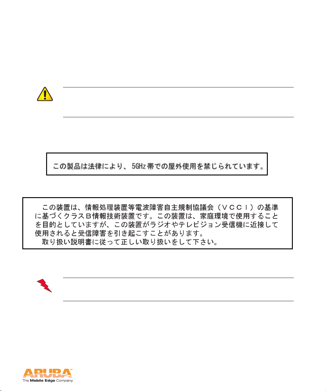
Indoor Restriction for 5GHz Frequency Range
VCCI - Class B
Europe
WARNING: This is a Class B product. In a domestic environment, this
product may cause radio interference in which case the user may be
required to take adequate measures.
This product complies with Directive 1999/5/EC as well as with EN55022 Class B
and EN55024 standards.
Aruba Networks provides a multi-language document containing country spec ific
restrictions, additional safety and regulatory information for the enclosed Access
Point. You may find this reference on our website at:
www.arubanetworks.com/pdf/0510272-01.pdf
Aruba AP 70 21
Installation Guide
Page 30
Product Specifica tions
Appendix B
Product Label
The product label is affixed to the chassis of the Aruba AP 70. The symbols on
the label are explained in this chapter.
Certifications
TABLE B-1 Certifications
Item Measurement
Electromagnetic
Compatibility
FCC Part 15 Class B, FCC Part 15 Class C
15.207/15.247
FCC Part 15 Class E 15.407
RSS 210 (CAN)
ICES-003 Class B
VCCI Class B
TELEC ARIB STD-T66
EN 61000-3, EN 61000-4-2, EN 61000-4-3,
EN 61000-4-4, EN 61000-4-5, EN 61000-4-6,
EN 61000-4-8, EN 61000-4-11, EN 55022, EN 55024
(89/336/EEC), 73/23/ECC, and 89/336/EEC
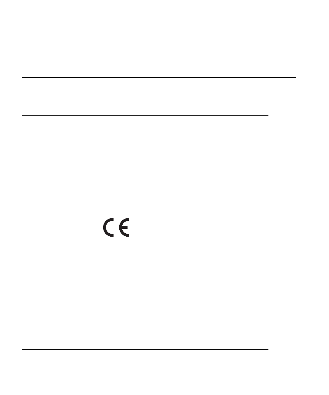
The CE approval mark on back of the
product indicates that it meets
European Directives 73/23/EEC and
89/336/EEC
R&TTE Directive:
EN 300 328, EN 301 489,
EN 301 893
AS/NZS 3548 Class B CIPPR22 Class B
RFS 29 (NZ)
Safety UL Listed (UL60950)
UL Listed (Canadian Electrical Code/CSA 22.2 No.
60950)
EN60950 / IEC60950
National Electrical Code Section 300-22(C)
Canadian Electrical Code, Part 1, CSA C22.1 Sections
2-128, 12-010(3), and 12-100
UL 2043 Plenum Rating
22 Aruba AP 70 0510159-02
Installation Guide September 2006
Page 31

Product Specifications
Product Features
z Wireless dual-band transceiver
z Varied antenna options:
z The Aruba AP 70 has a built-in array with dual, tri-band, omnidirectional
antennas for reception diversity.
z Protocol-independent networking functionality
z Supports IEEE 802.11a or IEEE 802.11b/g operation as an AP
z Supports IEEE 802.11a and IEEE 802.11b/g operation as an AM
z Compatible with IEEE 802.3af Power Over Ethernet (POE)
z Seamless connectivity to wired LANs augment existing networks quickly and
easily
z Can be centrally managed, configured, and upgraded through the Mobility
Controller to take advantage of network changes and security improvements
Ethernet Compatibility
The Aruba AP 70 attaches to 10/100 Mbps Ethernet (FE) LAN segments that
utilize 10Base-T/100Base-TX (twisted-pair) wiring. The device appears as an
Ethernet node and performs a routing function by moving packets between the
wired LAN and remote workstations on the wireless infrastructure.
Appendix B
Radio Characteristics
The Aruba AP 70 can be configured to support IEEE 802.11a or IEEE 802.11b/g
operation as an AP, and supports both IEEE 802.11a and IEEE 802.11b/g
operation as an AM:
z 802.11a provides a high data rate and reliable wireless connectivity
802.11a operation uses a radio modulation technique known as Orthogonal
Frequency Division Multiplexing (OFDM), and a shared collision domain
(CSMA/CA). It operates in the 5 Ghz Unlicensed National Information
Infrastructure (UNII) band. Data is tr ansmitted over a half-duplex r adio channel
operating at up to 54 Megabits per second (Mbps).
z 802.11b provides an alternative to wired LANs that can dramatically cut costs
802.11b operation uses the IEEE 802.11 High-Rate Direct Sequence (HRDS)
specification, and a shared collision domain (CSMA/CA). It operates in the 2.4
Ghz Industrial/Scientific/Medical (ISM) band. The ISM band is available
worldwide for unlicensed use. Data is transmitted at speeds of up to 11
Mbps.
z 802.11g provides a high data rate and is backwards compatible with 802.11b.
Aruba AP 70 23
Installation Guide
Page 32

Product Specifica tions
Appendix B
802.11g operation uses ODFM and a shared collision domain (CSMA/CA). It
operates in the 2.4 Ghz Industrial/Scientific/Medical (ISM) band. The ISM
band is available worldwide for unlicensed use. Data is transmitted at s peeds
of up to 54 Mbps.
Power Over Ethernet
The Aruba AP 70 supports the IEEE 802.3af standard for Power Over Ethern et
(POE). With this feature, the Aruba AP 70 can accept electrical power from a
compatible POE-capable device (such as the Aruba 5000 (with Line Card
LC-5000-24FE-2GE-SPOE), Aruba 2400, or Aruba 800) directly over the FE cable.
POE eliminates the need to provide separate power outlets in environments that
are difficult or undesirable to wire for electricity.
The Aruba AP 70 also supports “inline” and “midspan” POE devices for normal
operation. Inline power is POE that is integrated into FE ports and provides POE
directly to devices. Non-POE ports can have POE added by means of a mid-span
device that provides POE. The non-POE port is connected to a mid-span POE
port, and this mid-span port is connected to the device that requires POE.
Physical Description
Package Contents
The Aruba AP 70 package includes:
z One Aruba AP 70 Access Point
z Assorted documentation
Inform your supplier if there are any incorrect, missing or damaged parts. If
possible, retain the carton, including the original packing materials. Use them to
repack the product in case there is a need to return it.
Optional Items
The following optional items can also be ordered for the Aruba AP 70:
z Detachable antennas (Aruba AP 70 only)
z AC power adapter (5 VDC, 3 A) and power cord
z Serial breakout adapter for direct access to the AP console
z Mounting kit (modular cradle for walls and suspended ceilings)
Check with your Aruba sales representative for the availability of optional items.
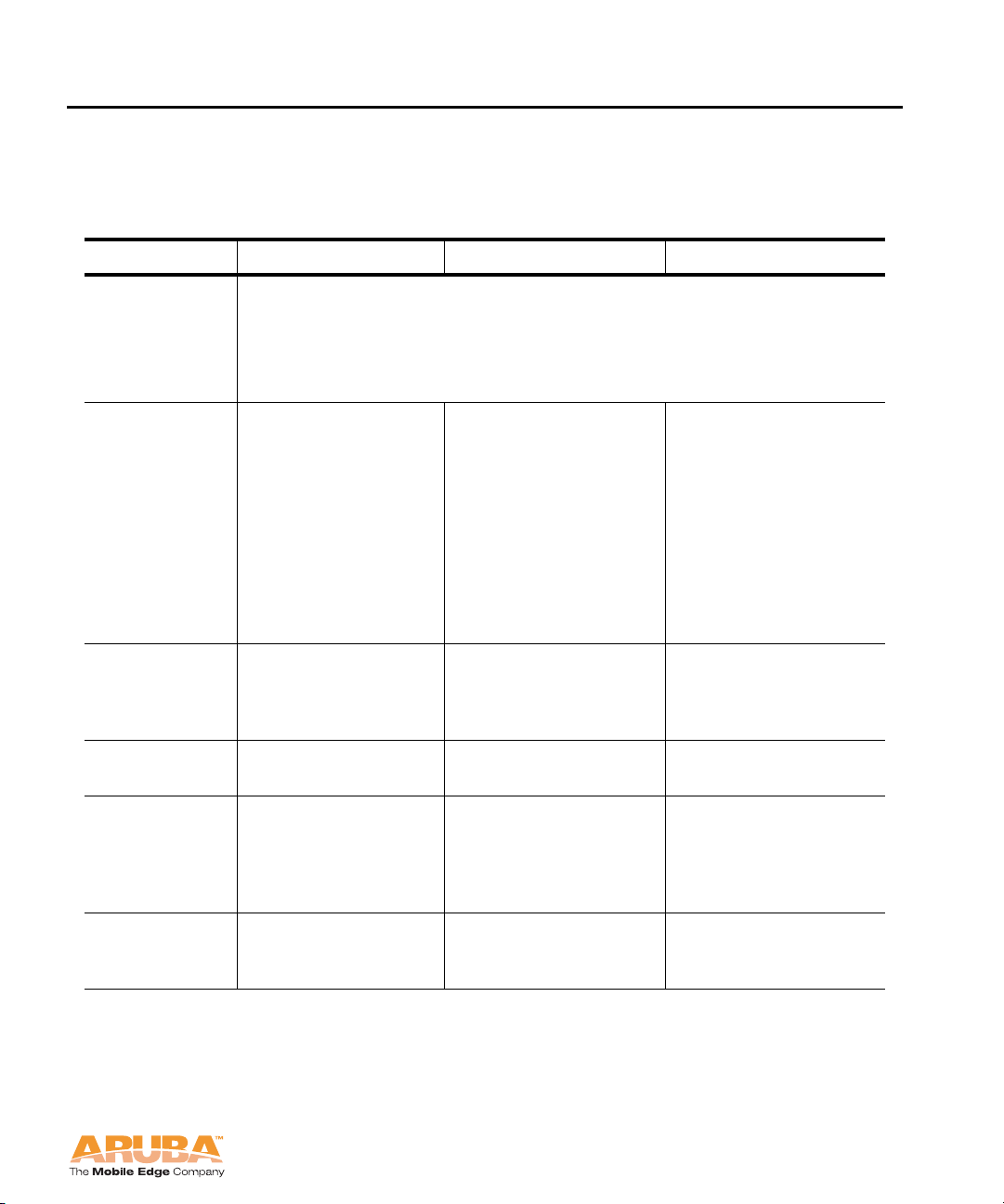
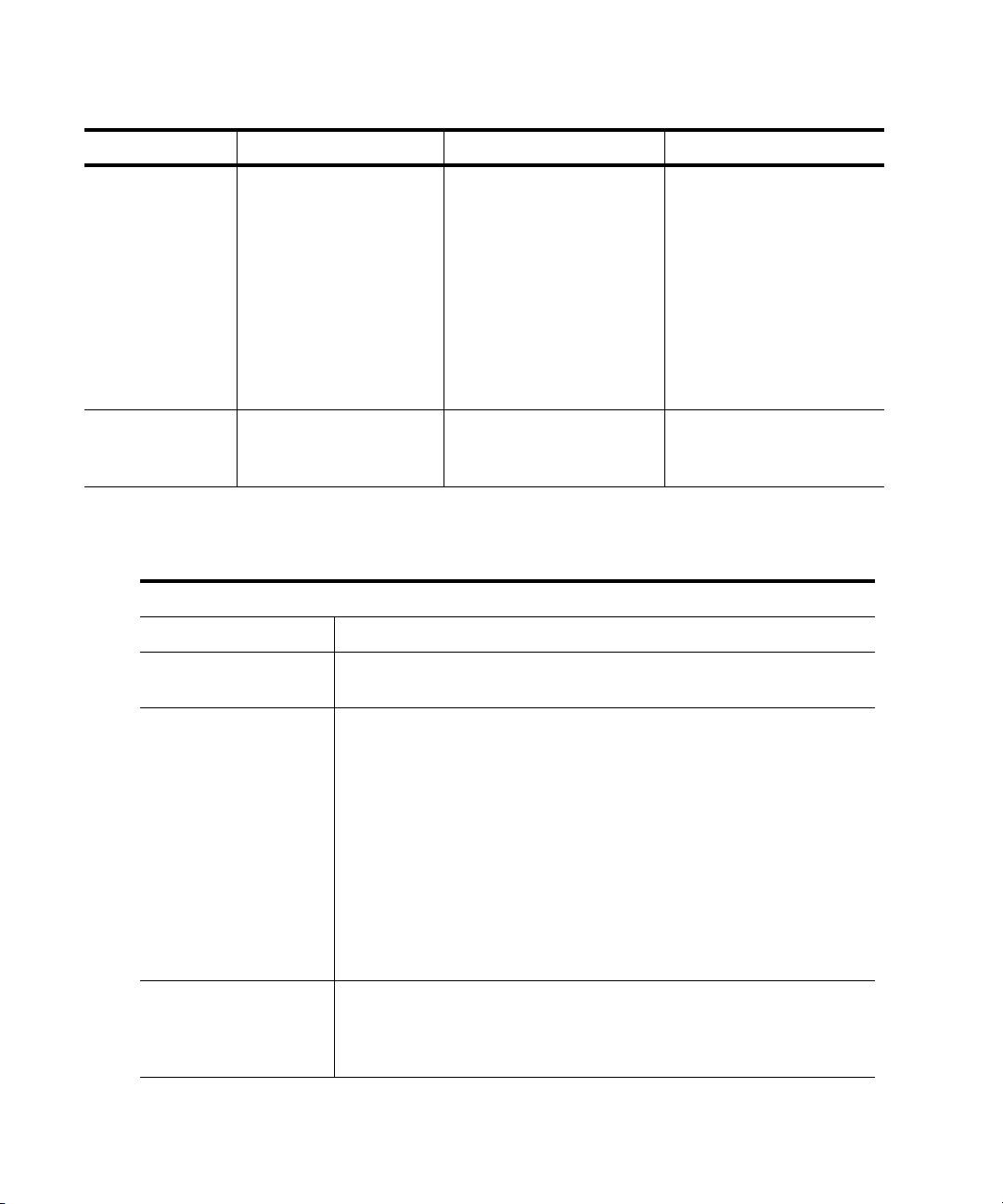
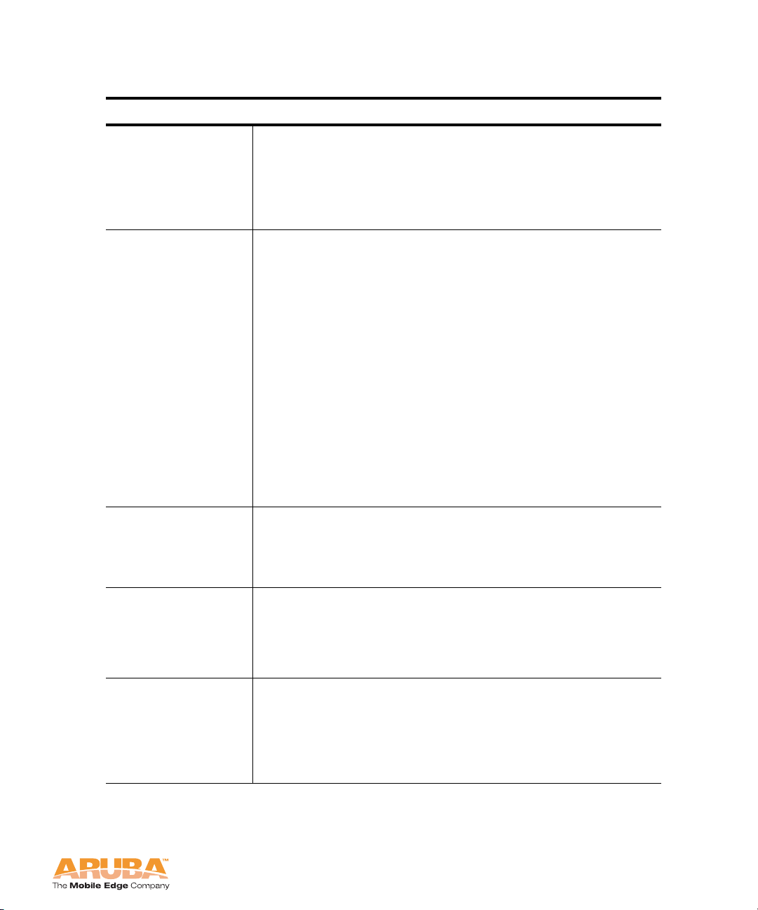
The following specifications apply to the Aruba AP 70 Access Points.
24 Aruba AP 70 0510159-02
Installation Guide September 2006
Page 33
AP 70 Specifications
TABLE B-2 Aruba AP 70 802.11 Specifications
Description 802.11a 802.11b 802.11g
Product Specifications
Appendix B
Integral
Antenna
Frequency
Band
Radio
Technology
Modulation
Type
Transmit
Power
Dual, diversity supporting omni-directional, high gain as follows:
2.4-2.5 Ghz 4.46 dBi
5.150 Ghz 7.21 dBi
5.350 Ghz 6.49 dBi
5.850 Ghz 5.23 dBi
z 5.150 ~ 5.250
Ghz (low band)
z 5.250 ~ 5.700
Ghz (ETSI)
z 5.500~ 5.825
Ghz (high
band)
z 5.725 ~ 5.825
Ghz (high
band)
Orthogonal
Frequency Division
Multiplexing
(OFDM)
BPSK, QPSK,
16-QAM, 64-QAM
Configurable by
system
administrator/
professional
installer
z 2.4 ~ 2.483 Ghz
(US, Canada &
ETSI)
z 2.4 ~ 2.497 Ghz
(Japan)
Complete country list
available at http://
www.arubanetworks.
com/products/aps/
certification
Direct Sequence
Spread Spectrum
(DSSS)
CCK, BPSK, QPSK CCK, BPSK, QPSK,
Configurable by
system
administrator/
professional
installer
z 2.412 ~ 2.462
Ghz (US, Canada)
z 2.412 ~ 2.472
Ghz (ETSI)
z 2.412 ~ 2.484
Ghz (Japan)
Complete country list
available at http://
www.arubanetworks.
com/products/aps/
certification
Orthogonal
Frequency Division
Multiplexing
(OFDM)
16-QAM, 64-QAM
Configurable by
system
administrator
Media
Access
Control
CSMA/CA with
ACK
CSMA/CA with ACK CSMA/CA with
ACK
Aruba AP 70 25
Installation Guide
Page 34
Product Specifica tions
Appendix B
TABLE B-2 Aruba AP 70 802.11 Specifications (Continued)
Description 802.11a 802.11b 802.11g
Operating
Channels
Data Rates 6, 9, 12, 18, 24,
z US & Canada:
8 external
antenna
12 internal
antenna
z ETSI: 19
z Japan: 4
Complete country list
available at http://
www.arubanetwork
s.com/products/aps/
certification
36, 48, 54 Mbps
z US & Canada: 11
z ETSI: 13
z Japan: 14
z
Complete country
list available at
http://
www.arubanetworks.com/products/aps/
certification
1, 2, 5.5, 11 Mbps
per channel
per channel
TABLE B-3 Aruba AP 70 Characteristics
Description
Maximum Clients 64
Multi-mode Radio
Band
Selectable via software
z US & Canada:
11
z ETSI: 13
z Japan: 14
Complete country list
available at http://
www.arubanetworks.
com/products/aps/
certification
6, 9, 12, 18, 24, 36,
48, 54 Mbps per
channel
Manageability: Management of all 802.11 parameters
Network Wide AP Management via:
z CLI
z WEB GUI
z SNMPv3
Access Point Profiles, Management by:
z Geographical Location
z BSSID
z Radio Type
Encryption
Support (AP and
40bit / 64bit / 128bit / 152bit WEP, TKIP, AES, WPA,
WPA2.0
Mobility
Controller)
26 Aruba AP 70 0510159-02
Installation Guide September 2006
Page 35
Product Specifications
TABLE B-3 Aruba AP 70 Characteristics (Continued)
Description
Appendix B
Physical
(HxWxD):
Interfaces
(Electrical):
Interfaces
(Mechanical):
Antenna Retracted: 167 x190 x 30 mm (6.57 x
7.48 x 1.18 in)
Antenna Deployed: 293 x 190 x 30 mm (11.54 x
7.48 x 1.18 in)
Weight 510 grams (18 oz)
2 x 10/100 Base-TX RJ-45 auto-sensing Ethernet
interfaces:
Port ENET0
z Supports auto-sensing MDI/MDX
z Supports Power Over Ethernet 48V DC /
250mA (802.3af compliant)
z Supports Serial Over Ethernet
Port ENET1
z Does not support auto-sensing
z Supports Power Over Ethernet 48V DC /
250mA (802.3af compliant)
z Does not support Serial Over Ethernet
USB ver 2.0 Interface
Standard Kensington MicroSaver Security Cable
Interface (cable not supplied)
Wall, wall gang box, ceiling mount kit interface
(optional - part number AP-70-MNT)
Visual Indicators
(LEDs)
Power
Requirements
Ready -- Power on/off
Ethernet (0/1) Link status / Activity
(Radio Mode) 802.11a +b/g access point/air
monitor mode
External AC power or POE
5V DC / 3A supplied externally via optional,
country-specific AC adapter kits
48V DC / 250mA Power Over Ethernet (802.3af
compliant)
Aruba AP 70 27
Installation Guide
Page 36

Product Specifica tions
Appendix B
TABLE B-3 Aruba AP 70 Characteristics (Continued)
Description
Output Power 100 mW maximum (or lower as configured on the
Aruba Mobility Controller to comply with local
regulatory requirements)
Power
12W maximum
Consumption
Operating
Environment
0 ºC to 50 ºC (32 ºF to 122 ºF) AP
0 ºC to 40 ºC (32 ºF to 104 ºF) AC Mains Power
Adapter Kit
Storage
Environment
0 ºC to 70 ºC (32 ºF to 158 ºF) AP
-20 ºC to 70 ºC (-4 ºF to 158 ºF) AC Mains Power
Adapter Kit
Humidity 5 to 95%, non-condensing AP
15 to 85% RH AC Mains Power Adapter Kit
5 to 90% RH Storage Humidity AC Mains Power
Adapter Kit
Altitude 3,048 m (10,000 feet) maximum
Standards
Compliance
Ethernet IEEE 802.3 / IEEE 802.3u
Power Over Ethernet IEEE 802.3af
Wireless IEEE 802.11a/b/g
USB 2.0
28 Aruba AP 70 0510159-02
Installation Guide September 2006
Page 37
Proper Disposal of Aruba Equipment
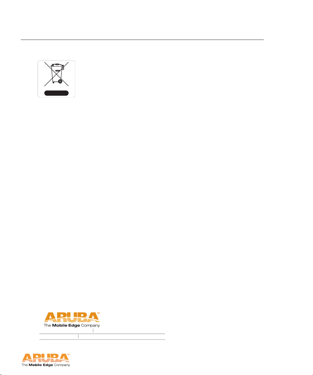
This product at end of life is subject to separate collection and
treatment in the EU Member States, Norway, and Switzerland
and therefore is marked with the symbol shown at the left.
Treatment applied at end of life of these products in these
countries shall comply with the applicable national laws
implementing Directive 2002/96EC on Waste of Electrical and
Electronic Equipment (WEEE).
The WEEE Directive 2002/96/EC and RoHS (Restriction of
Hazardous Substances) Directive 2002/95/EC sets collection,
recycling and recovery targets for various categories of
electrical products and their waste.
The Restriction on Hazardous Substances Directive (RoHS)
(2002/95/EC), which accompanies the WEEE Directive, bans
the use of heavy metals and brominated flame-retardants in
the manufacture of electrical and electronic equipment.
Specifically, restricted materials under the RoHS Directive are
Lead (including Solder used in PCB's), Cadmium, Mercury,
Hexavalent Chromium, and Bromine.
Product Specifications
Appendix B
Aruba declares compliance with the European Union (EU)
WEEE Directive (2002/96/EC). For more information on WEEE,
refer to:
http://www.dti.gov.uk/sustainability/weee/
1322
crossman avenue sunnyvale california
tel
408 2 27 450 0
fax
408 2 27 455 0
94089
Aruba AP 70 29
Installation Guide
Page 38

Product Specifica tions
Appendix B
30 Aruba AP 70 0510159-02
Installation Guide September 2006
 Loading...