

HP A-MSR900, A-MSR900-W, A-MSR900-W(NA), A-MSR920, A-MSR920-W Installation Manual
...
HP A-MSR900 Router Series
Installation Guide
Abstract
This document guides you through installation of HP A Series products, including installing the device,
connecting to the network, hardware management, and troubleshooting.
Part number: 5998-1409
Software version: CMW520-R22
Docume
nt version: 6PW101-20120626
09P19

Legal and notice information
© Copyright 2012 Hewlett-Packard Development Company, L.P.
No part of this documentation may be reproduced or transmitted in any form or by any means without
prior written consent of Hewlett-Packard Development Company, L.P.
The information contained herein is subject to change without notice.
HEWLETT-PACKARD COMPANY MAKES NO WARRANTY OF ANY KIND WITH REGARD TO THIS
MATERIAL, INCLUDING, BUT NOT LIMITED TO, THE IMPLIED WARRANTIES OF MERCHANTABILITY
AND FITNESS FOR A PARTICULAR PURPOSE. Hewlett-Packard shall not be liable for errors contained
herein or for incidental or consequential damages in connection with the furnishing, performance, or use
of this material.
The only warranties for HP products and services are set forth in the express warranty statements
accompanying such products and services. Nothing herein should be construed as constituting an
additional warranty. HP shall not be liable for technical or editorial errors or omissions contained herein.

Contents
Product overview ·························································································································································· 1
A-MSR900 panel views ···················································································································································· 1
A-MSR900-W panel views ··············································································································································· 2
A-MSR900-W(NA) panel views ······································································································································ 2
A-MSR920 panel views ···················································································································································· 3
A-MSR920-W panel views ··············································································································································· 4
A-MSR920-W(NA) panel views ······································································································································ 4
Preparing for installation ············································································································································· 6
Safety recommendations ·················································································································································· 6
Site requirements ······························································································································································· 6
EMI ············································································································································································· 7
Lightning protection ·················································································································································· 7
Installation tools ································································································································································· 7
Pre-installation checklist ···················································································································································· 8
Installing the router ····················································································································································· 10
Installation prerequisites ················································································································································ 10
Installation flowchart ······················································································································································ 10
Installing the router ························································································································································· 11
Installing the router on a workbench ··················································································································· 12
Installing the router on a wall ······························································································································ 12
Grounding the router ············································································································································ 13
Installing an antenna ············································································································································· 15
Connecting interface cables ································································································································· 16
Connecting the console cable and setting terminal parameters ······································································ 17
Setting console terminal parameters ··················································································································· 18
Connecting the power adapter ···························································································································· 21
Verifying the installation ······································································································································· 21
Powering on the router ········································································································································· 22
Configuring basic settings for the router ············································································································· 23
Troubleshooting ·························································································································································· 24
Power supply failure ······················································································································································ 24
Power LED is off ····················································································································································· 24
System configuration problems ····································································································································· 24
No terminal display ·············································································································································· 24
Garbled terminal display······································································································································ 25
No response from the serial port ························································································································· 25
Password loss ································································································································································· 25
User password loss ··············································································································································· 25
Super password loss ············································································································································· 26
Interface module, cable, and connection failure ········································································································ 26
Support and other resources ····································································································································· 27
Contacting HP ································································································································································ 27
Subscription service ·············································································································································· 27
Related information ························································································································································ 27
Documents ······························································································································································ 27
Websites ································································································································································ 27
Conventions ···································································································································································· 28
iii

Appendix A Technical specifications ······················································································································· 109H30
48HA-MSR900 specifications ·············································································································································· 110H30
49HAntenna specifications ·················································································································································· 111H31
50HAppendix B LEDs ························································································································································ 112H32
51HA-MSR900/A-MSR900-W/A-MSR900-W(NA)·········································································································· 113H32
52HA-MSR920/A-MSR920-W/A-MSR920-W(NA)·········································································································· 114H33
53HIndex ··········································································································································································· 115H34
iv
Product overview
#
yp
This chapter shows the chassis panels of the HP A-MSR900 Router Series models listed in Table 1. The
chassis panel views shown may differ slightly from the actual panels.
Table 1 The HP A-MSR900 Router Series includes the following models:
J
T
JF812A A-MSR900
JF814A A-MSR900-W
JG207A A-MSR900-W(NA)
JF813A A-MSR920
JF815A A-MSR920-W
JG208A A-MSR920-W(NA)
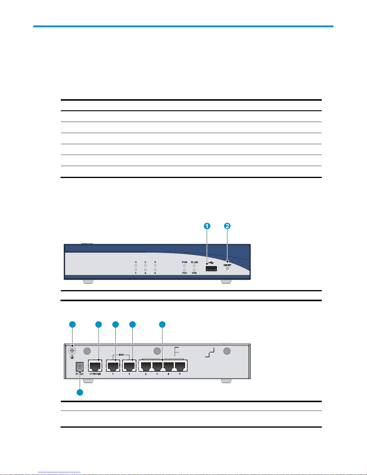
A-MSR900 panel views
Figure 1 A-MSR900 front panel
e
(1) USB port (2) Reset button
Figure 2 A-MSR900 rear panel
1 2 3 4 5
6
(1) Grounding screw (2) Console port (3) Ethernet WAN port ETH0
(4) Ethernet WAN port ETH1 (5) Ethernet LAN ports (ETH2 to
ETH5)
1
(6) Power adapter port

A-MSR900-W panel views
Figure 3 A-MSR900-W front panel
(1) USB port (2) Reset button
Figure 4 A-MSR900-W rear panel
(1) Grounding screw (2) Console port (3) Ethernet WAN port ETH0
(4) Ethernet WAN port ETH1 (5) Ethernet LAN ports (ETH2 to
ETH5)
(7) Power adapter port
A-MSR900-W(NA) panel views
Figure 5 A-MSR900-W(NA) front panel
(1) USB port (2) Reset button
(6) Antenna port
2

Figure 6 A-MSR900-W(NA) rear panel
(1) Grounding screw (2) Console port (3) Ethernet WAN port ETH0
(4) Ethernet WAN port ETH1 (5) Ethernet LAN ports (ETH2 to
ETH5)
(7) Power adapter port
A-MSR920 panel views
Figure 7 A-MSR920 front panel
(6) Antenna port
(1) USB port (2) Reset button
Figure 8 A-MSR920 rear panel
(1) Grounding screw (2) Console port (3) Ethernet WAN port ETH0
(4) Ethernet WAN port ETH1 (5) Ethernet LAN ports (ETH2 to
ETH5)
(7) Power adapter port
(6) Ethernet LAN ports (ETH6 to
ETH9)
3

A-MSR920-W panel views
Figure 9 A-MSR920-W front panel
(1) USB port (2) Reset button
Figure 10 A-MSR920-W rear panel
(1) Grounding screw (2) Antenna port (3) Console port
(4) Ethernet WAN port ETH0 (5) Ethernet WAN port ETH1 (6) Ethernet LAN ports (ETH2 to
(7) Ethernet LAN ports (ETH6 to
ETH9)
(8) Antenna port (9) Power adapter port
A-MSR920-W(NA) panel views
Figure 11 A-MSR920-W(NA) front panel
(1) USB port (2) Reset button
ETH5)
4
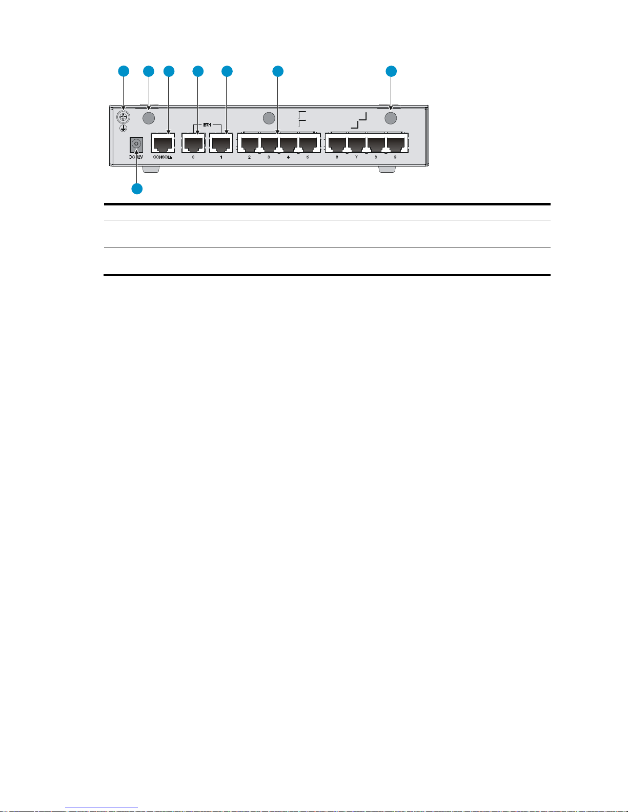
Figure 12 A-MSR920-W(NA) rear panel
1 2 3 4 5 6 7
8
(1) Grounding screw (2) Antenna port (3) Console port
(4) Ethernet WAN port ETH0 (5) Ethernet WAN port ETH1 (6) Ethernet LAN ports (ETH2 to
(7) Ethernet LAN ports (ETH6 to
ETH9)
(8) Antenna port (9) Power adapter port
ETH5)
5

Preparing for installation
W
p
y
p
Safety recommendations
ARNING!
Before installation and operation, read all of the safety instructions in the
Guide
supplied with your router.
General safety recommendations follow:
• Turn off all power and remove all power cables before opening the chassis.
• Unplug all power and external cables before moving the chassis.
• Before installation, locate the emergency power switch so that you can shut off power immediately if
necessary.
• Always wear an ESD-preventive wrist strap when installing the device.
• Do not stare into an open optical interface. The light can cause permanent eye damage.
• Use a good grounding system. This is essential for reliable operation.
• Confirm that the resistance between the chassis and the ground is less than 1 ohm.
Compliance and Safety
Site requirements
The router can only be used indoors.
This section provides information about temperature, humidity, cleanness, and air quality requirements, as
well as rack-mounting requirements and protection against damage from lightning and EMI.
Table 2 Temperature and humidity requirements
Tem
erature Relative humidit
0°C to 45°C (32°F to 113°F) 5% to 90%
Table 3 Dust concentration limit in the equipment room
Substance Concentration limit (
Dust particles
NOTE:
Dust particle diameter ≥ 5 μm
articles/m3)
≤ 3 x 10⁴
(No visible dust on desk in three days)
6

Table 4 Harmful gas concentration limits
g
EMI
Gas Max. (m
SO2 0.2
H2S 0.006
NH
3
Cl
2
0.05
0.01
/m3)
To prevent overheating:
• Provide adequate clearance for air flow, including at least 10 cm [3.94 in] ventilation space around
the router's air intake and outlet vents.
• Make sure the site has an adequate cooling system.
EMI from any source adversely affects the router.
To prevent EMI:
• Use electromagnetic shielding when necessary.
• Take measures against interference from the power grid.
• Position the router as far as possible from any power source's grounding equipment or light-
prevention equipment.
• Position the router as far as possible from radio transmitters, radar, and all high-voltage or high-
frequency equipment.
Lightning protection
To protect the router from lightning:
• Make sure the grounding cable of the chassis is grounded properly.
• Make sure the grounding terminal of the AC power receptacle is grounded properly.
• Install a lightning arrester at the input end of the power supply.
• Install a lightning arrester at the input end of outdoor signal lines (for example, E1/T1 line) to which
the router’s interface modules are connected.
Installation tools
Accessories provided with the router
• Power cord
• Console cable
• Grounding cable
7

User-supplied tools and equipment
q
• Phillips screwdriver P1 – 100 mm, P2 – 150 mm and P3 – 250 mm
• Plain screwdriver P4 – 75 mm
• Screws with various specifications
• Meters and equipment such as HUB, terminal, and multimeter
• ESD-preventive gloves or wrist strap, ESD-preventive mat, anti-static bags
• Electric drill (for wall-mounting the router)
• Hammer
Pre-installation checklist
Table 5 Pre-installation checklist
Item Re
Installation
site
Ventilation
• There is a minimum clearance of 10 cm (3.9 in) around
• The installation site ventilation system is adequate.
Temperature 0°C to 45°C (32°F to 113°F)
Relative humidity 5% to 90% (noncondensing)
Cleanness Dust concentration ≤ 3 × 10⁴ particles/m3
• The equipment and floor are properly grounded.
• The equipment room is dust-controlled.
• Humidity and temperature are maintained at proper
• Wear an ESD-preventive wrist strap when inspecting or
ESD prevention
• Place any removed memory module, CF card, or
• Touch only the edges, not any electronic components,
• Take measures to protect the power system from the
• Keep the protection ground of the router as far away
EMI prevention
• Keep the router far away from radio transmitters, radar,
• Use electromagnetic shielding when necessary.
uirements Yes No
the router chassis intake and exhaust vents for heat
dissipation.
levels.
handling a circuit board.
interface module face-up on an antistatic workbench or
in an antistatic bag.
when inspecting or handling a memory module, CF
card, or interface module.
power grid system.
from the grounding device or lightning protection
grounding device as possible.
and high-frequency or high-voltage devices.
8

Item Requirements Yes No
• The grounding cable of the chassis is grounded
properly.
• The grounding terminal of the AC power receptacle is
Lightning protection
grounded properly.
• A port lightning arrester is installed. (Optional)
• A power lightning arrester is installed. (Optional)
• A signal lightning arrester is installed at the input end
of an external signal cable. (Optional)
• Install a UPS.
Safety
precautions
Tools
Reference
Electricity safety
Workbench
• In case of emergency during operation, switch off the
external power switch.
• The workbench is stable.
• The workbench is grounded properly.
• The router is far away from any sources of heat or moisture.
• The emergency power switch in the equipment room is identified and
accessible.
• Installation accessories supplied with the router are ready.
• User-supplied tools are ready.
• Documents shipped with the router are available.
• Online documents are available.
9
 Loading...